Ahmed Abdmouleh To cite this versionboutillon/articles/these/... · 2018-04-18 · scientifiques de...
132
HAL Id: tel-01769283 https://tel.archives-ouvertes.fr/tel-01769283 Submitted on 17 Apr 2018 HAL is a multi-disciplinary open access archive for the deposit and dissemination of sci- entific research documents, whether they are pub- lished or not. The documents may come from teaching and research institutions in France or abroad, or from public or private research centers. L’archive ouverte pluridisciplinaire HAL, est destinée au dépôt et à la diffusion de documents scientifiques de niveau recherche, publiés ou non, émanant des établissements d’enseignement et de recherche français ou étrangers, des laboratoires publics ou privés. Non-binary LDPC codes associated to high order modulations Ahmed Abdmouleh To cite this version: Ahmed Abdmouleh. Non-binary LDPC codes associated to high order modulations. Signal and Image Processing. Université de Bretagne Sud, 2017. English. <NNT : 2017LORIS452>. <tel-01769283>
Transcript of Ahmed Abdmouleh To cite this versionboutillon/articles/these/... · 2018-04-18 · scientifiques de...

HAL Id: tel-01769283https://tel.archives-ouvertes.fr/tel-01769283
Submitted on 17 Apr 2018
HAL is a multi-disciplinary open accessarchive for the deposit and dissemination of sci-entific research documents, whether they are pub-lished or not. The documents may come fromteaching and research institutions in France orabroad, or from public or private research centers.
L’archive ouverte pluridisciplinaire HAL, estdestinée au dépôt et à la diffusion de documentsscientifiques de niveau recherche, publiés ou non,émanant des établissements d’enseignement et derecherche français ou étrangers, des laboratoirespublics ou privés.
Non-binary LDPC codes associated to high ordermodulations
Ahmed Abdmouleh
To cite this version:Ahmed Abdmouleh. Non-binary LDPC codes associated to high order modulations. Signal and ImageProcessing. Université de Bretagne Sud, 2017. English. <NNT : 2017LORIS452>. <tel-01769283>

THESE / UNIVERSITE DE BRETAGNE-SUD sous le sceau de l’Université Bretagne Loire
pour obtenir le titre de
DOCTEUR DE L’UNIVERSITE DE BRETAGNE-SUD
Mention : STIC
Ecole doctorale:SICMA
Présentée par :
ABDMOULEH AHMED
Préparée à l’UMR 6285
Université de Bretagne Sud
Lab-STICC
Codes correcteurs d'erreurs NB-
LDPC associés aux modulations
d'ordre élevé.
Thèse soutenue le 12 septembre 2017
devant le jury composé de :
Jean-François HELARD Directeur de la recherche – INSA Rennes / président
Charly POULLIAT
Professeur des Universités – INP-ENSEEIHT / rapporteur
Christophe JEGO Professeur des Universités – IPB/ENSEIRB-MATMECA / rapporteur
Olivier BERDER Directeur de la recherche – Université de Rennes / examinateur
Andrew HACKETT Directeur Technique – CTO, France Brevets / invité
Charbel ABDEL-NOUR
Encadrant
Laura CONDE-CANENCIA Encadrant
Catherine DOUILLARD
Co-directeur de thèse
Emmanuel BOUTILLON
Directeur de thèse
Codes correcteurs d'erreurs NB-LDPC associés aux modulations d'ordre élevé Ahmed Abdmouleh 2017

2Codes correcteurs d'erreurs NB-LDPC associés aux modulations d'ordre élevé Ahmed Abdmouleh 2017

Table des matières
1 Introduction 1
2 Non-Binary LDPC codes 52.1 Algebraic definition of Galois Fields GF(q) . . . . . . . . . . . . . . . . . . 5
2.1.1 Groups . . . . . . . . . . . . . . . . . . . . . . . . . . . . . . . . . 52.1.2 Fields . . . . . . . . . . . . . . . . . . . . . . . . . . . . . . . . . . 62.1.3 Galois Fields . . . . . . . . . . . . . . . . . . . . . . . . . . . . . . 6
2.2 NB-LDPC codes defined over GF(q) . . . . . . . . . . . . . . . . . . . . . . 82.2.1 Low-Density parity-check Codes . . . . . . . . . . . . . . . . . . . . 82.2.2 NB-LDPC codes over GF(q) : an extension of LDPC codes . . . . . . 10
2.3 Iterative decoding of NB-LDPC codes . . . . . . . . . . . . . . . . . . . . . 102.3.1 Belief-propagation algorithm . . . . . . . . . . . . . . . . . . . . . . 122.3.2 log-BP algorithm . . . . . . . . . . . . . . . . . . . . . . . . . . . . 142.3.3 Min-Sum and Extented Min-Sum algorithm . . . . . . . . . . . . . . 15
2.4 Binary vs. Non-Binary LDPC codes . . . . . . . . . . . . . . . . . . . . . . 182.4.1 NB-LDPC vs binary LDPC simulation results . . . . . . . . . . . . . 20
2.5 Conclusion . . . . . . . . . . . . . . . . . . . . . . . . . . . . . . . . . . . 21
3 Transmissions using high order modulations : Coded Modulation (CM) andBit-Interleaved Coded Modulation (BICM) schemes 233.1 Transmission channel modeling . . . . . . . . . . . . . . . . . . . . . . . . 23
3.1.1 additive white gaussian noise channel . . . . . . . . . . . . . . . . . 233.1.2 The fading channel model . . . . . . . . . . . . . . . . . . . . . . . 243.1.3 The fading channel with erasure model . . . . . . . . . . . . . . . . 26
3.2 High order modulations . . . . . . . . . . . . . . . . . . . . . . . . . . . . 273.2.1 Transmission of modulated signal . . . . . . . . . . . . . . . . . . . 283.2.2 Bit and Symbol rates . . . . . . . . . . . . . . . . . . . . . . . . . . 283.2.3 Quadrature amplitude modulation (QAM) . . . . . . . . . . . . . . . 29
3.3 Coded Modulation scheme . . . . . . . . . . . . . . . . . . . . . . . . . . 30
i
Codes correcteurs d'erreurs NB-LDPC associés aux modulations d'ordre élevé Ahmed Abdmouleh 2017

ii TABLE DES MATIÈRES
3.3.1 System model . . . . . . . . . . . . . . . . . . . . . . . . . . . . . 303.3.2 NB-LDPC codes associated to modulations with the same order . . . 303.3.3 Theoretical limits for transmissions : mutual information computation . 32
3.4 Bit Interleaved Coded Modulation . . . . . . . . . . . . . . . . . . . . . . . 353.4.1 System model . . . . . . . . . . . . . . . . . . . . . . . . . . . . . 363.4.2 Theoretical limits for transmissions : mutual information computation . 37
3.5 Channel capacity . . . . . . . . . . . . . . . . . . . . . . . . . . . . . . . . 383.5.1 Gaussian channel capacity . . . . . . . . . . . . . . . . . . . . . . . 383.5.2 Rayleigh channel capacity . . . . . . . . . . . . . . . . . . . . . . . 39
3.6 Mutual information and capacity curves . . . . . . . . . . . . . . . . . . . . 403.7 Conclusion . . . . . . . . . . . . . . . . . . . . . . . . . . . . . . . . . . . 43
4 Signal Space Diversity optimization based on the analysis of Mutual Infor-mation 454.1 Signal Space Diversity . . . . . . . . . . . . . . . . . . . . . . . . . . . . . 46
4.1.1 SSD Technique description . . . . . . . . . . . . . . . . . . . . . . 474.1.2 Intuitive explanation of the SSD technique added value . . . . . . . . 49
4.2 Examples of application of the SSD . . . . . . . . . . . . . . . . . . . . . . 514.3 optimization of the SSD rotation angle . . . . . . . . . . . . . . . . . . . . . 52
4.3.1 BER-based rotation angle selection . . . . . . . . . . . . . . . . . . 524.3.2 Uncoded SER Upper bound approach to perform the angle selection 53
4.4 SSD with BICM scheme : the DVB-T2 standard as an example of application 544.4.1 The DVB-T2 standard . . . . . . . . . . . . . . . . . . . . . . . . . 544.4.2 Rotation angle choice parameters for the DVB-T2 standard . . . . . . 54
4.5 Mutual Information : Metric for performance enhancement . . . . . . . . . . 564.6 Rotation angle optimization via MI maximization . . . . . . . . . . . . . . . 57
4.6.1 Mutual information as a function of the rotation angle . . . . . . . . . 584.6.2 Best rotation angle as a function of the SNR . . . . . . . . . . . . . 624.6.3 Mutual information gain provided by the best rotation angles . . . . . 664.6.4 Mutual information as a function of the SNR . . . . . . . . . . . . . . 68
4.7 Simulation results and performance comparison . . . . . . . . . . . . . . . 704.8 Conclusion . . . . . . . . . . . . . . . . . . . . . . . . . . . . . . . . . . . 72
5 Joint modulation and coding optimization with NB-LDPC codes 735.1 NB-LDPC codes construction . . . . . . . . . . . . . . . . . . . . . . . . . 74
5.1.1 Non-null positions choice in the PCM . . . . . . . . . . . . . . . . . 755.1.2 NB coefficients choice in the PCM . . . . . . . . . . . . . . . . . . . 76
5.2 NB-LDPC codes and modulation joint optimization : motivation facts . . . . . 775.3 Euclidean distance evaluation . . . . . . . . . . . . . . . . . . . . . . . . . 785.4 Euclidean distance VS Hamming distance in coded modulation . . . . . . . 805.5 Distance spectrum evaluation . . . . . . . . . . . . . . . . . . . . . . . . . 82
Codes correcteurs d'erreurs NB-LDPC associés aux modulations d'ordre élevé Ahmed Abdmouleh 2017
TABLE DES MATIÈRES iii
5.5.1 Definition of distance spectrum . . . . . . . . . . . . . . . . . . . . 825.5.2 Union bound derivation . . . . . . . . . . . . . . . . . . . . . . . . . 835.5.3 Proposed method to evaluate the first terms of the DS . . . . . . . . 84
5.6 Incidence of Gray mapping choice on Euclidean distance and Distance Spec-trum . . . . . . . . . . . . . . . . . . . . . . . . . . . . . . . . . . . . . . 85
5.7 Joint optimization of mapping and NB-LDPC matrix coefficients . . . . . . . 885.8 Simulation results and interpretations . . . . . . . . . . . . . . . . . . . . . 90
5.8.1 Decoding performance of the elementary check node . . . . . . . . . 905.8.2 Decoding performance of the NB-LDPC joint optimization based construc-
ted matrix . . . . . . . . . . . . . . . . . . . . . . . . . . . . . . . . 915.9 Conclusion . . . . . . . . . . . . . . . . . . . . . . . . . . . . . . . . . . . 93
6 Conclusions and Perspectives 956.1 Conclusions . . . . . . . . . . . . . . . . . . . . . . . . . . . . . . . . . . 956.2 Perspectives . . . . . . . . . . . . . . . . . . . . . . . . . . . . . . . . . . 97
Codes correcteurs d'erreurs NB-LDPC associés aux modulations d'ordre élevé Ahmed Abdmouleh 2017

iv
Codes correcteurs d'erreurs NB-LDPC associés aux modulations d'ordre élevé Ahmed Abdmouleh 2017

Table des figures
2.1 Tanner Graph of an LDPC code . . . . . . . . . . . . . . . . . . . . . . . . 92.2 Tanner Graph of a NB-LDPC code. . . . . . . . . . . . . . . . . . . . . . . 112.3 Tanner Graph of an LDPC code. . . . . . . . . . . . . . . . . . . . . . . . . 132.4 The forward/backward CN processor with dc =4. . . . . . . . . . . . . . . . 172.5 Binary vs. NB-LDPC BER decoding over AWGN channel, for rate = 1/2,
Nb=3000, and BPSK modulation. . . . . . . . . . . . . . . . . . . . . . . . 212.6 Binary vs. NB-LDPC decoding over Rayleigh channel, for rate = 1/3,Nb=64800,
and 256-QAM modulation. . . . . . . . . . . . . . . . . . . . . . . . . . . . 22
3.1 16-QAM modulation with Gray mapping. . . . . . . . . . . . . . . . . . . . 293.2 Coded Modulation transmission scheme over Rayleigh channel with erasure. 313.3 Bit Interleaved Coded Modulation transmission scheme . . . . . . . . . . . 363.4 MI of M-QAM modulation with Shannon limit for AWGN channel. . . . . . . . 413.5 64-QAM MI under CM and BICM schemes. . . . . . . . . . . . . . . . . . . 423.6 MI of M-QAM modulation with Shannon limit for Rayleigh channel. . . . . . . 42
4.1 Coded Modulation transmission scheme with the SSD technique . . . . . . 484.2 16-QAM modulation (Constellation before transmission) . . . . . . . . . . . 494.3 16-QAM modulation with severe fading on Q axis . . . . . . . . . . . . . . 494.4 Rotated 16-QAM modulation (Constellation before transmission) . . . . . . 494.5 Rotated 16-QAM modulation with severe fading on Q axis . . . . . . . . . . 494.6 QPSK modulation with fading . . . . . . . . . . . . . . . . . . . . . . . . . 504.7 Rotated QPSK modulation with severe fading . . . . . . . . . . . . . . . . 504.8 QPSK modulation with an erasure on the Q component . . . . . . . . . . . 514.9 Rotated QPSK modulation with an erasure on the Q component . . . . . . 514.10 BER performance of the proposed solution systems with different labeling
over different rotation angles at SNR=12.8 dB, Rayleigh channel. . . . . . . 534.11 SER for 16-QAM as a function of rotation angle α for different values of SNR
and Mt. . . . . . . . . . . . . . . . . . . . . . . . . . . . . . . . . . . . . 54
v
Codes correcteurs d'erreurs NB-LDPC associés aux modulations d'ordre élevé Ahmed Abdmouleh 2017

vi TABLE DES FIGURES
4.12 DVB-T2 standard rotation angle choice parameters : 16-QAM modulation . . 554.13 Mutual information as a function of the rotation angle α for CM and BICM.
SNR = 10, 15 and 25 dB. Rayleigh fading channel and 16-QAM modulation. 584.14 Mutual information as a function of the rotation angle α for CM and BICM
schemes. SNR = 15, 25 and 30 dB. Rayleigh fading channel and 256-QAMmodulation. . . . . . . . . . . . . . . . . . . . . . . . . . . . . . . . . . . . 59
4.15 Mutual information as a function of the rotation angle α for CM and BICM.Rayleigh channel and Rayleigh channel with erasure (Pe ∈ 0.1, 0.2, 0.3).SNR = 15 dB and 64-QAM modulation. . . . . . . . . . . . . . . . . . . . . 60
4.16 Mutual information as a function of the rotation angle α for CM and BICM.Rayleigh channel and Rayleigh channel with erasure (Pe ∈ 0.1, 0.2, 0.3).SNR = 25 dB and 64-QAM modulation. . . . . . . . . . . . . . . . . . . . . 61
4.17 Rotation angle that maximizes mutual information, as a function of the SNR,for the Rayleigh channel and Rayleigh channel with 10% erasures. 16-QAMmodulation. . . . . . . . . . . . . . . . . . . . . . . . . . . . . . . . . . . . 63
4.18 Rotation angle that maximizes mutual information, as a function of the SNR,for the Rayleigh channel and Rayleigh channel with 10% erasures. 256-QAMmodulation. . . . . . . . . . . . . . . . . . . . . . . . . . . . . . . . . . . . 64
4.19 Rotation angle that maximizes mutual information, as a function of the SNR,for the Rayleigh channel and Rayleigh channel with 10%, 20% and 30%erasures. 64-QAM modulation. . . . . . . . . . . . . . . . . . . . . . . . . 65
4.20 Maximum MI gain with SSD, as a function of the SNR, for the Rayleigh chan-nel and Rayleigh channel with 10% erasures. 16-QAM modulation. . . . . . 66
4.21 Maximum MI gain with SSD, as a function of the SNR, for the Rayleigh chan-nel and Rayleigh channel with 10% erasures. 256-QAM modulation. . . . . . 67
4.22 Maximum MI gain with SSD, as a function of the SNR, for the Rayleigh chan-nel and Rayleigh channel with 10%, 20% and 30%, erasures. 256-QAM mo-dulation. . . . . . . . . . . . . . . . . . . . . . . . . . . . . . . . . . . . . 68
4.23 CM and BICM mutual information curves for a 16-QAM modulation over fastflat fading Rayleigh channel (without erasures and with 10% erasures) . . . 69
4.24 CM and BICM mutual information curves for a 256-QAM modulation over fastflat fading Rayleigh channel (without erasures and with 10% erasures) . . . 70
4.25 FER simulation for 3/4-rate BICM-GF(2) and CM-GF(256) schemes over thefast flat Rayleigh fading channel, with and without Rotated Constellation . . . 71
4.26 FER simulation for 9/10-rate BICM-GF(2) and CM-GF(256) schemes overthe fast flat Rayleigh fading channel, with and without Rotated Constellation . 71
5.1 Mapping π0 : Gray Mapping of the DVB-T2 standard for 64-QAM modulation 815.2 Mapping π1 . . . . . . . . . . . . . . . . . . . . . . . . . . . . . . . . . . . 865.3 Mapping π2 . . . . . . . . . . . . . . . . . . . . . . . . . . . . . . . . . . . 875.4 Mapping π′0 . . . . . . . . . . . . . . . . . . . . . . . . . . . . . . . . . . . 89
Codes correcteurs d'erreurs NB-LDPC associés aux modulations d'ordre élevé Ahmed Abdmouleh 2017
TABLE DES FIGURES vii
5.5 Mapping π′1 . . . . . . . . . . . . . . . . . . . . . . . . . . . . . . . . . . . 895.6 Mapping π′2 . . . . . . . . . . . . . . . . . . . . . . . . . . . . . . . . . . . 895.7 Mapping π′3 . . . . . . . . . . . . . . . . . . . . . . . . . . . . . . . . . . . 895.8 Mapping π′0 . . . . . . . . . . . . . . . . . . . . . . . . . . . . . . . . . . . 895.9 Mapping π′5 . . . . . . . . . . . . . . . . . . . . . . . . . . . . . . . . . . . 895.10 Union bound and FER performance for the single parity-check coded modu-
lations (C, π)0, (C, π)1 and (C, π)2. . . . . . . . . . . . . . . . . . . . . . . 915.11 EMS decoding performance of a N = 48 GF(64)-LDPC code with coded
modulations (C, π)0, (C, π)1 and (C, π)2, for a maximum of 100 erroneousframes . . . . . . . . . . . . . . . . . . . . . . . . . . . . . . . . . . . . . 92
Codes correcteurs d'erreurs NB-LDPC associés aux modulations d'ordre élevé Ahmed Abdmouleh 2017

viii
Codes correcteurs d'erreurs NB-LDPC associés aux modulations d'ordre élevé Ahmed Abdmouleh 2017
Liste des tableaux
2.1 Primitive polynomials . . . . . . . . . . . . . . . . . . . . . . . . . . . . . . 72.2 Binary representation of symbols . . . . . . . . . . . . . . . . . . . . . . . 7
4.1 Values of the rotation angles in the DVB-T2 standard . . . . . . . . . . . . . 564.2 Mutual information for CM and BICM. SNR = 10 dB. Rayleigh fading channel
and 16-QAM. . . . . . . . . . . . . . . . . . . . . . . . . . . . . . . . . . . 644.3 Mutual information for CM and BICM in bit/s/Hz. SNR = 25 dB. Rayleigh
fading channel and 256-QAM. . . . . . . . . . . . . . . . . . . . . . . . . . 65
5.1 First terms of DS for coded modulations (C, π)0, (C, π)1 and (C, π)2 . . . . . 90
ix
Codes correcteurs d'erreurs NB-LDPC associés aux modulations d'ordre élevé Ahmed Abdmouleh 2017

"Believe you can and you are halfway there"
Theodore Roosevelt
x
Codes correcteurs d'erreurs NB-LDPC associés aux modulations d'ordre élevé Ahmed Abdmouleh 2017

ABBREVIATIONS
LDPC Low-Density Parity-Check
NB Non-Binary
NB-LDPC Non-Binary Low-Density Parity-Check
MAP Maximum a-posteriori
SSD Signal Space Diversity
QAM Quadrature Amplitude Modulation
AWGN Additive White Gaussian Noise
GF Galois Field
CN Check Node
VN Variable Node
ML Maximum Likelihood
BP Belief Propagation
LLR Logarithmic Likelihood Ratio
EMS Extended Min-Sum
MS Min-Sum
SNR Signal to-Noise Ratio
CM Coded modulation
BICM Bit Interleaved Coded Modulation
MI Mutual Information
xi
Codes correcteurs d'erreurs NB-LDPC associés aux modulations d'ordre élevé Ahmed Abdmouleh 2017
SFN Single-Frequency Networks
DVB-T2 Digital Video Broadcasting Terrestrial, the second generation
CSI Channel State Information
BER Bit Error Rate
SER Symbol Error Rate
FER Frame Error Rate
FEC Forward Error Correction
QPSK Quadrature Phase-Shift keying
DS Distance Spectrum
xii
Codes correcteurs d'erreurs NB-LDPC associés aux modulations d'ordre élevé Ahmed Abdmouleh 2017

DEDICATION
To all people who helped me to follow my dreams...
xiii
Codes correcteurs d'erreurs NB-LDPC associés aux modulations d'ordre élevé Ahmed Abdmouleh 2017

xiv
Codes correcteurs d'erreurs NB-LDPC associés aux modulations d'ordre élevé Ahmed Abdmouleh 2017
ACKNOWLEDGEMENTS
Finally, after an intensive work on my dissertation, I’m glad to write this note of thanks to thepeople who helped and supported me during my PhD. This PhD was carried out at the laboratoryLab-STICC (Laboratoire des Sciences et Techniques de l’Information, de la Communication et dela Connaissance) in Université Bretagne Sud and Telecom Bretagne.
My foremost thanks are dedicated to Emmanuel Boutillon, for his guidance through the workon this thesis, for the continuous support, and his immense knowledge. He supported me in allsteps of my thesis research and redaction. I cannot find a better mentor for my PhD study. I wouldlike to thank Catherine Douillard, who has been a tremendous mentor for me. Thank you so muchfor your patience and continuous support. I would like to thank my supervisor Charbel Abdel-Nourfor his advises and interesting discussions that helped me overcome obstacles in my PhD. I wouldlike to thank Laura Conde-Canoncia for her kindness and help during difficult moments, she wasmy ultimate refuge in times of trouble.
During my PhD I spent good time in Brest, Lorient, Kaiserslautern and Lannion. This allowedme to meet friends that were very nice and helpful, they became like a family for me. We spentunforgettable moments and we had several interesting discussions about meaning of life and theworld were we live.
I am forever thankful to my parents. The are the key of my success. They have both scarifieda lot to help me achieving my dreams. My brother and sister are such a wonderful gift, thank youfor everything you have done for me.
xv
Codes correcteurs d'erreurs NB-LDPC associés aux modulations d'ordre élevé Ahmed Abdmouleh 2017

xvi
Codes correcteurs d'erreurs NB-LDPC associés aux modulations d'ordre élevé Ahmed Abdmouleh 2017

ABSTRACTNon-binary LDPC codes associated to high-order modulations
Abdmouleh AhmedDepartment Electronique, Telecom - Bretagne
12 Septembre 2017
This thesis is devoted to the analysis of the association of non-binary LDPC codes(NB-LDPC) with high-order modulations. This association aims to improve the spectralefficiency of future wireless communication systems. Our approach tries to take maxi-mum advantage of the straight association between NB-LDPC codes over a Galois Fieldwith modulation constellations of the same cardinality.
We first investigate the optimization of the signal space diversity technique obtai-ned with the Rayleigh channel (with and without erasure) thanks to the rotation of theconstellation. To optimize the rotation angle, the mutual information analysis is performedfor both coded modulation (CM) and bit-interleaved coded modulation (BICM) schemes.The study shows the advantages of coded modulations over the state-of-the-art BCIMmodulations. Using Monte Carlo simulation, we show that the theoretical gains translateinto actual gains in practical systems.
In the second part of the thesis, we propose to perform a joint optimization of constel-lation labeling and parity-check coefficient choice, based on the Euclidian distance ins-tead of the Hamming distance. An optimization method is proposed. Using the optimizedmatrices, a gain of 0.2 dB in performance is obtained with no additional complexity.
xvii
Codes correcteurs d'erreurs NB-LDPC associés aux modulations d'ordre élevé Ahmed Abdmouleh 2017

xviii
Codes correcteurs d'erreurs NB-LDPC associés aux modulations d'ordre élevé Ahmed Abdmouleh 2017

RÉSUMÉNon-binary LDPC codes associated to high-order modulations
Abdmouleh AhmedDépartement Electronique, Telecom - Bretagne
12 Septembre 2017
De nos jours, nous vivons dans un monde numérique de plus en plus intercon-necté. Les systèmes de communication futurs doivent relever des défis majeurs : assurerl’échange d’un volume de données important, un nombre croissant d’appareils connec-tés, et plus de données à pourvoir par utilisateur. Cependant, la réponse à ces exigencesimportantes doit prendre en compte certaines limites de transmission. En 1948, ClaudeShannon a montré qu’une transmission connait une certaine limite théorique de trans-mission appelé capacité du canal, définie comme la quantité maximale d’informationspouvant être envoyées sans erreurs en utilisant un système de communication numé-rique. Depuis, nous avons vu l’émergence de plusieurs codes correcteurs d’erreurs telsque les codes de Hamming, les codes algébriques, les codes LDPC (Low-Density parity-check) et, plus récemment, les codes turbo et les codes polaires.
Les codes correcteurs d’erreurs se classent en deux grandes catégories : les codesen blocs et les codes convolutionnels. Dans le cas des codes en blocs, le message estenvoyé sur plusieurs blocs de données séparés, et l’encodeur traite chaque bloc indé-pendamment. Par conséquent, l’encodeur doit attendre la réception d’un bloc entier pourdémarrer. Dans le cas des codes convolutionnels, le codeur traite le message d’une fa-çon continue et génère séquentiellement les symboles de redondance sans avoir besoindu message complet. La plupart des normes de communication actuelles utilisent unede ces deux catégories de codes correcteurs d’erreur.
Les codes correcteurs d’erreurs à faible densité (LDPC) sont une classe de codes deblocs linéaires. Initialement présentés par Gallager en 1963, les codes LDPC se caracté-risent par une matrice de parité qui contient un petit nombre d’éléments non nuls. Malgréleur excellente performance, cette classe de codes a été ignorée pendant trois décen-nies en raison de sa complexité de décodage qui a dépassé les capacités des systèmesélectroniques de l’époque. Mackay et al. ont repris les codes LDPC au milieu des années1990 et ils ont montré que ces codes permettent d’atteindre des performances prochesde la limite de Shannon en utilisant les algorithmes de décodage souples. Au cours desdeux dernières décennies, les codes LDPC ont connus un progrès spectaculaire, leurcapacité de décodage pour différents modèles de canaux est devenu assez intéressantece qui a attiré l’intérêt de la communauté scientifique. Les avancements théoriques ontboosté le transfert de ces codes correcteurs d’erreurs au domaine industriel. Maintenant,les codes LDPC jouent un rôle majeur dans la définition de plusieurs normes commeDVB-S2, WI-MAX, DSL, W-LAN. Les performances de décodage des codes LDPC ontatteint des capacités de correction très proches des limites théoriques (seulement 0.0045dB de la limite de Shannon), ce qui en fait parmi les meilleures codes correcteurs d’er-reurs expérimentée jusqu’à présent. Cependant, ces performances proches de la limitede Shannon sont observés pour les codes associés à des blocs de très grande longueur(séquence de 106 -bit).
Plus tard, Gallager a étendu la définition des codes LDPC sur les alphabets nonbinaires pour proposer les codes LDPC non binaires. Ces codes LDPC non binaires,définis sur les corps de Galois de dimensions strictement supérieurs à 2, ont offert unebonne alternative aux codes LDPC binaires en raison de leur capacité de correction su-périeure. Les récentes études ont confirmé l’amélioration apportée par ces codes LDPCnon binaires par rapport à leurs homologues binaires, en particulier pour les mots de
xix
Codes correcteurs d'erreurs NB-LDPC associés aux modulations d'ordre élevé Ahmed Abdmouleh 2017

code de petite et moyenne taille. Le gain apporté par ces codes LDPC non binaires de-vient encore plus important lorsque les symboles sont envoyés en utilisant des modula-tions d’ordre élevé. Le nombre de publications croissant liées aux décodeurs LDPC nonbinaires confirme l’intérêt grandissant de la communauté scientifique pour cette famillede codes. Plusieurs auteurs ont proposé dans la littérature des constructions efficacesdes codes LDPC non binaires ainsi que bon nombre d’algorithmes de décodage pour lescodes LDPC non binaires. L’algorithme de propagation de croyance est l’un des déco-deurs itératifs les plus connus. Cependant, le gain de performance fourni par les codesLDPC non binaires s’accompagne d’une importante complexité de décodage. Pour uncode LDPC défini sur le champ Galois GF (q), la complexité du décodage est de l’ordreO(q2). Ce fait rend l’utilisation des codes LDPC non binaires un compromis entre l’amé-lioration de la performance et l’augmentation de la complexité du décodage.
De nos jours, la coexistence de différentes applications radio (téléphonie mobile, ré-seaux sans fil, radiodiffusion terrestre, communications par satellite, etc.) limite les res-sources spectrales. En d’autres termes, les données transmises dans de nombreused’applications continuent de croître et le nombre d’utilisateurs augmente constamment,cela sans être couplée par une augmentation des ressources spectrales. Dans ce contexte,les opérateurs et les fabricants du monde numérique visent à maximiser l’efficacité spec-trale des systèmes, définis comme le taux de transmission utile par unité de bande occu-pée. La solution ultime pour contrer le manque de ressources en spectre de fréquenceet pour répondre aux besoins de transmissions à débit élevé, est l’utilisation de modu-lations d’ordre élevé. Les communications radio-mobiles et par satellite ont déjà intégrédes modulations à ordre élevé dans leurs schémas de transmission. Au cours des deuxdernières décennies, un progrès significatif a bénéficié à la recherche sur des systèmesde transmission ayant une efficacité spectrale élevé. Cela a permis de faire face à la de-mande industrielle. Le schéma de modulation codé, qui combine les codes correcteursd’erreur avec les modulations à haut ordre, devient essentiel pour les canaux qui sontlimités en bande spectrale.
Les motivations des travaux de cette thèse viennent de deux faits principaux. Toutd’abord, au cours de la dernière décennie, les codes LDPC non binaires ont été biendéveloppés pour les corps de Galois d’ordre q > 2. Le deuxième fait est que le besoincroissant de transmissions d’haut débit a conduit à une croissance de l’utilisation desmodulations à ordre élevé dans les nouvelles normes de transmission. Par conséquent,l’association de codes LDPC non binaires avec des modulations à ordre élevé mérited’être étudiée. En fait, lors de l’association d’un code LDPC binaire à une modulationM-are, le démappeur (MAP) crée des probabilités au niveau binaire pour le décodeur. Ladépendance entre les bits implique que le démapper génère des probabilités corréléesau niveau binaire. Par conséquent, le décodeur est initialisé avec des messages déjà cor-rélés par le canal. L’utilisation de démappeur itératif atténue partiellement cet effet, maisaugmente la complexité totale du décodeur. À l’inverse, dans le cas NB (code LDPCnon binaires avec modulation NB), la dépendance entre les messages est réduite et lesprobabilités des symboles sont moins corrélées. Si les dimensions du code LDPC nonbinaires et la modulation coïncident, le décodeur LDPC non binaires sera initialisé avecdes messages non corrélés, ce qui entraînera une meilleure performance au niveau desalgorithmes de décodage. Par conséquent, les codes LDPC non binaires offrent toujoursde meilleures performances pour la modulation d’ordre élevé. Des résultats prometteursété observés suite à l’association d’un code LDPC défini sur GF (64) avec la modulationen 64-QAM pour transmission dans un canal gaussien. En outre, lorsque la dimension ducorps de Galois des codes LDPC non binaires est égale à la dimension de la modulation,la relation directe entre la modulation et les symboles du code LDPC non binaire élimine
xx
Codes correcteurs d'erreurs NB-LDPC associés aux modulations d'ordre élevé Ahmed Abdmouleh 2017

le besoin de démapping itératif entre le décodeur et Maximum a Détecteur postérieur(MAP). Par conséquent, l’utilisation de codes LDPC non binaires, réduit la latence chezles récepteurs et offre des gains de codage plus élevés. Lorsque les tailles de constella-tion augmentent, un gain de codage supplémentaire est offert par les codes LDPC nonbinaires aux codes LDPC binaire. Par conséquent, plus l’efficacité spectrale augmente,plus la taille des constellations continuent à croître. Par conséquent, ces avantages descodes LDPC non binaires lorsqu’ils sont associés à des modulations à ordre élevé aurontune influence majeure dans les normes de transmission de la prochaine génération.
Cette thèse est consacrée à l’association des codes LDPC non binaires aux modu-lations à d’ordre élevé. A travers les travaux de cette thèse, nous essayons d’atteindredeux objectifs principaux. Tout d’abord, nous nous intéressons à ressortir les avantagesdu bon ajustement entre les codes LDPC non binaires et les modulations à ordre élevé,surtout lorsqu’ils ont la même dimension (relation direct entre les symboles et les pointsde la constellation).Deuxièmement, nous proposerons des méthodes novatrices pouraméliorer les systèmes existants qui utilisent des codes LDPC non binaires dans uncontexte de transmission avec une grande efficacité spectrale.
Cette thèse englobe quatre chapitres dans lesquels nous étudions les résultats etles avantages de l’association des codes LDPC non binaires avec des modulations àordre élevé. Dans le premier chapitre de la thèse, les codes LDPC non binaires sontintroduits. Des notions mathématiques utiles à leur étude sont présentées, ainsi quequelques exemples d’algorithmes de décodage. Enfin, certaines des études de perfor-mance existantes sont présentées pour comparer les codes LDPC non binaires à leurshomologues binaires. Dans le deuxième chapitre, nous nous concentrons sur les diffé-rents éléments de la communication numérique et les concepts liés aux modulations àordre élevé. Nous présentons une modélisation des canaux de transmission considérésdans cette thèse, avant de présenter les schémas de modulation codée et les schémasde modulations codée entrelacées au niveau bit. Ensuite, nous mettons en évidenceleurs limites de transmission théoriques. Enfin, la diversité en espace et signal appelé enanglais Signal Space Diversity (SSD), est présentée et certaines de ses applications etméthodes d’optimization sont introduites. Dans la troisième partie de cette thèse, nousprésentons notre première contribution lors de l’utilisation de la technique SSD dans lecontexte d’une transmission à haute efficacité spectrale, la méthode d’optimization dela technique SSD proposé est basée sur la maximisation de l’information mutuelle. Uneanalyse des limites théoriques de transmission est réalisée pour le canal de Rayleighet canal de Rayleigh avec effacement. Sur la base d’une maximisation de l’informationmutuelle, nous proposons les meilleurs angles de rotation pour la technique SSD. Unimpact positif sur la performance théorique est obtenu. Les résultats de la simulationrévèlent que cette technique de diversité, la SSD, peut encore être améliorée en com-paraison avec les méthodes d’optimization existantes. Dans le quatrième chapitre, nousproposons une nouvelle méthode pour optimizer le schéma de transmission en modula-tion codé. L’idée principale consiste à effectuer une optimization conjointe des du codagede canal (codes LDPC non binaires) et de la modulation (modulation M-QAM). En fait, laméthode proposée exploite l’avantage d’utiliser un schéma de modulation avec un ordreégal à celui du GF sur lequel les codes LDPC non binaires sont définis. Un gain deperformance est obtenu sans ajouter la moindre complexité par rapport aux systèmesexistants.
xxi
Codes correcteurs d'erreurs NB-LDPC associés aux modulations d'ordre élevé Ahmed Abdmouleh 2017

xxii
Codes correcteurs d'erreurs NB-LDPC associés aux modulations d'ordre élevé Ahmed Abdmouleh 2017

Chapitre 1
Introduction
Nowadays, we live in a world that is becoming increasingly connected, and the upco-ming communication systems must meet crucial challenges : a bigger volume of data, moreinterconnected devices and higher data flow to be consumed by users. However, the answerto these important demands faces certain limitations. In 1948, Claude Shannon had shownthat one of these limitations is the channel capacity, defined as the maximum amount ofinformation that can be reliably sent by employing a digital communication system. Since1948, several error correction codes have been proposed, such as algebraic codes, Ham-ming codes, Low-Density parity-check (LDPC) codes and more recently, turbo codes andpolar codes. Among the listed correction codes two main families can be distinguish : blockcodes and convolutional codes. For the first code family, the message is separated intoblocks of data and the encoder processes these blocks separately. Therefore, the encodermust receive the whole block to start encoding. For the second family code, the encoderprocesses the message continuously and generates the redundancy symbols without anyneed to get the full message. Most of the current communication standards call for one ofthese two families of error correction codes.
LDPC codes are a class of linear block codes, originally presented by Gallager in 1963.LDPC codes are characterized by a sparse Parity Check Matrix (PCM) that contains asmall number of nonzero elements. Despite their excellent performance, LDPC codes wereignored till the mid 1990 because of their decoding complexity that is superior to the ca-pacity of electronic systems of that time. When Mackay et al. revisited the LDPC codes in1996 [1], they showed that these codes offer near Shannon limit performance when deco-ded by means of probabilistic soft decision decoding algorithms. LDPC codes have knownspectacular advances in the last decades. Their capacity approaching performance for awide range of channel models attracts the interest of the scientific community. Fundamentaltheoretical advancement encourages the transfer of these correcting codes to the industrialdomain. Now LDPC codes play a major role in the definition of several standards like DVB-S2, WI-MAX, DSL, W-LAN. The importance of LDPC coding has still grown by pushing itscapacity (only 0.0045 dB from the Shannon limit), which makes them the best experiencederror correcting code till now. However these near Shannon’s limit performance is obtained
1
Codes correcteurs d'erreurs NB-LDPC associés aux modulations d'ordre élevé Ahmed Abdmouleh 2017

2 CHAPITRE 1. INTRODUCTION
for randomly constructed codes of very large block lengths (106-bit sequence).Later on, Gallager extended the definition of LDPC codes on non-binary alphabets to
propose non-binary LDPC (NB-LDPC) codes. These NB-LDPC codes are defined over Ga-lois Fields of order strictly higher than 2. They offered a good alternative to LDPC codes dueto their enhanced correction capacity. Recent studies confirmed that NB-LDPC codes givebetter performance compared to their binary counterparts, especially for small to moderatecodewords. Moreover NB-LDPC codes provide additional performance gain when symbolsare sent using high-order modulations. The increasing number of publications related tonon-binary LDPC decoders confirms the growing interest of scientific community for thesecodes. Several authors have proposed in the literature effective constructions of NB-LDPCcodes, and number of efficient decoding algorithms for NB-LDPC codes, i.e. Belief pro-pagation algorithm, one of the most known iterative decoders. However, the performancegain provided by NB-LDPC codes is accompanied by an important decoding complexity.For an LDPC code defined over the Galois field GF(q), the decoding complexity is of theorder O(q2). This fact make the use of NB-LDPC codes a tradeoff between performanceenhancement and the increase of decoding complexity.
Nowadays, the coexistence of different radio applications (mobile telephony, wirelessnetworks, terrestrial broadcasting, satellite communications, etc.), limits the spectral re-sources. In addition, the transmitted data in a wide range of applications continues to growwhile the number of users is constantly increasing. In this context, operators and manu-facturers aim at maximizing the spectral efficiency of the systems, defined as the usefultransmission rate per unit of occupied band. The ultimate solution to counter the lack offrequency spectrum resources, and to meet the need of high data rate transmissions, isthe use of high order modulations. The radio-mobile and satellite communication channelshave already integrated high order modulations in their transmission schemes. In the lasttwo decades, research on systems that use high spectral efficiency transmission has bene-fited from significant progress, making it possible to cope with the industrial demand. Thecoded modulation (CM) scheme, which combines error correcting codes with high ordermodulations, becomes essential for channels that are limited both in power and in spectralband.
The motivation behind this thesis comes from two main facts. First, in the last decade,there has been tremendous interest in NB-LDPC codes defined over high-order Galoisfields GF(q), with q >> 2. The second fact is that the increasing need of high data ratetransmissions has led to a growing need of using high order modulations in the new trans-mission standards. Therefore a good association of NB-LDPC codes with high order mo-dulations is worth investigating. In fact, when associating a binary LDPC code to an M-arymodulation, the Maximum a-posteriori (MAP) demapper creates probabilities at the binarylevel for the decoder. The dependency between the bits implies that the demapper gene-rates likelihoods that are already correlated at the binary level. Therefore the decoder isinitialized with messages already correlated by the channel. The use of iterative demap-ping partially mitigates this effect but increases the whole decoder complexity. Conversely,
Codes correcteurs d'erreurs NB-LDPC associés aux modulations d'ordre élevé Ahmed Abdmouleh 2017

3
in the NB case (NB-LDPC code with NB modulation), the dependence between messagesis reduced and the symbol likelihoods are less correlated. If the NB-LDPC code is definedin the same GF order as the order of the modulation, the NB-LDPC decoder will be ini-tialized with non-correlated messages, which leads to better performance of the decodingalgorithms. Therefore, NB-LDPC codes provide always better performance for high ordermodulation. Promising results have already been obtained with the association of an LDPCcode over GF(64) with 64-QAM for transmission in Gaussian channel. Furthermore, thedirect relation between modulation and NB-LDPC codes eliminates the need for iterative-demapping between the decoder and MAP detector. Hence employing NB-LDPC codes,reduces the latency at the receivers and offers higher coding gains. When the constel-lation sizes increase, additional coding gains are obtained with NB-LDPC. Therefore, asthe transmission rates continue to increase, the constellation sizes will continue to grow ;consequently, these benefits of NB-LDPC codes associated with high order modulationswill have a major influence in the next generation transmission standards.
This thesis is dedicated to the association of NB-LDPC codes with high order modula-tions. Through this thesis we try to achieve two main goals. First, we are interested to bringout the advantage of the good fit between NB-LDPC codes and high order modulations,especially when they are of the same order. Second, we will try to propose some innovativemethods to ameliorate the existing systems that already use NB-LDPC codes with highspectral efficiency transmission.
This thesis encompasses four distinct chapters, in which we investigate the outcomeand advantages of the association of NB-LDPC codes with high order modulations. In thefirst chapter of the thesis, NB-LDPC codes are introduced. Useful mathematical notionsabout NB-LDPC codes are presented, as well as the existing decoding algorithms. Andsome of the existing performance studies are presented to show that NB-LDPC codes areasymptotically better than their binary counterparts. In the second chapter, we focus on thevarious elements of digital communication and the concepts related to the high order modu-lations. We present a modelization of the considered transmission channels in this thesis,before presenting the Coded Modulation, and the Bit Interleaved Coded Modulation (BICM)schemes. Then, we highlight some of their theoretical transmission limits. In the third partof this thesis, a diversity technique, called signal space diversity (SSD), is presented andsome of its applications and optimization methods are introduced. Then, we present our firstcontribution when employing the SSD technique in the context of high spectral efficiencytransmission, the mutual information based SSD technique optimization. To make such anoptimization, an analysis of the theoretical transmission limits is done under both Rayleighand Rayleigh with erasure channels. Based on Mutual Information maximization, we pro-pose the best rotation angles for the SSD technique, for the BICM that uses a binary errorcontrol code, and for the CM that uses a NB-LDPC code of same order of the modulation.A positive impact on the theoretical performance is obtained. Both theory and simulationresults shows that the association of CM with SSD improves the performance compared toBICM. For example, with a 9
10 rate code, SSD with CM brings 1.3 dB of gain, while when
Codes correcteurs d'erreurs NB-LDPC associés aux modulations d'ordre élevé Ahmed Abdmouleh 2017
4 CHAPITRE 1. INTRODUCTION
we use the SSD with BICM only 0.3 dB of gain is obtained. In addition, simulation resultsreveal that the SSD technique can be further ameliorated, when comparing to the state-of-the-art optimization methods. In the fourth chapter, we propose a new method to design anadvanced high-spectral efficiency communication for CM transmission scheme. The mainidea consists in performing a joint optimization of both channel coding (NB-LDPC codes)and modulation (M-QAM modulation). To be precise, the joint optimization is done on theconstellation mapping and the non-null entries of the NB-LDPC code. This optimization isbased on the evaluation of the distance spectrum of the Euclidean distances between allpossible codewords. In fact, the proposed method exploits the advantage of using a modu-lation scheme with an order equal to the one of the GF over which the NB-LDPC codes aredefined. A gain of performance is obtained free of any additional complexity compared toexisting schemes.
Part of the work done during the PhD has been published in [2] it was about the SSDtechnique optimization ; and in [3] to present the joint NB-LDPC code and mapping optimi-zation which was also protected by a patent in [4].
Codes correcteurs d'erreurs NB-LDPC associés aux modulations d'ordre élevé Ahmed Abdmouleh 2017

Chapitre 2
Non-Binary LDPC codes
This chapter presents the background and state-of-the-art information about Non-BinaryLow-Density parity-check (NB-LDPC) codes and the principles of their decoding process.In Section 2.1, we introduce the notion of Galois fields necessary for defining NB-LDPCcodes, before presenting the NB-LDPC codes in Section 2.2, as an extension of the LDPCcodes. Then, decoding algorithms of NB-LDPC codes is the subject of Section 2.3. Finally,we conclude this chapter in Section 2.4 by comparing the performance of LDPC and NB-LDPC codes using state-of-the-art-codes, over additive white Gaussian noise (AWGN) andRayleigh channels.
2.1 ALGEBRAIC DEFINITION OF GALOIS FIELDS GF(Q)
Classical algebra is known to study the most commonly used sets N, Z, R and C builtwith arithmetic operations such as addition and multiplication. However, modern algebrais characterized by a higher level of abstraction ; the concept of operation is defined asan application that returns a symbol from two or more symbol combination. This allowsthe scientists to extend the definition of error correction codes to sets other than classicalensembles. In this PhD thesis, we have a special interest non-binary LDPC codes definedon Galois Fields. In order to present a clear definition of Galois field, we first show the basicalgebraic structures and their internal composition laws. The content of this section wasmainly extracted from [5, 6, 7].
2.1.1 GROUPS
Let G be a set of elements. A binary operation « ∗ » on G is a function that assigns toa couple of elements a and b a unique element c = a ∗ b in G. A binary operation « ∗ » onG is associative if, for any a, b, and c in G, a ∗ (b ∗ c) = (a ∗ b) ∗ c
A set G on which a binary operation « ∗ » is defined is called a group if the followingconditions are satisfied :
5
Codes correcteurs d'erreurs NB-LDPC associés aux modulations d'ordre élevé Ahmed Abdmouleh 2017

6 CHAPITRE 2. NON-BINARY LDPC CODES
1. The binary operation « ∗ » is associative.
2. G contains an identity element e of G, with ∀a ∈ G, a ∗ e = e ∗ a = a.
3. For any element a ∈ G, there exists another element a′ ∈ G such that a ∗ a′ =
a′ ∗ a = e ; a and a
′are inverse to each other.
A group G is called commutative if its operation « ∗ » also satisfies the following condi-tion : for any a and b in G, a ∗ b = b ∗a. Finally, a Group G satisfies the following properties
— The identity element in a group G is unique.Proof : If e and e
′are identity elements ∈ G. Then e
′ = e′ ∗ e = e.
— Every element has a unique inverse.Proof : If a
′and a
′′are inverse to a, then a
′= a′ ∗ e = a
′ ∗ a ∗ a′′ = e ∗ a′′ = a′′
2.1.2 FIELDS
Let F be a set of elements defined with two binary operations, addition « + », andmultiplication « ∗ ». The set F together with the two binary operations « + » and « ∗ » is afield if the following conditions are satisfied :
1. (F,+) is a commutative group. The identity element 0 of the addition operation iscalled the zero element of F .
2. (F − 0, ∗) is a commutative group. The identity element of the multiplicationoperation 1 is called the unit element of F .
3. Multiplication is distributive over addition ; ∀ a, b and c ∈ F , a∗(b+c) = a∗b+a∗c.
2.1.3 GALOIS FIELDS
A Galois field has a finite order, which is either a prime number or the power of a primenumber. A field of order q = np GF(np) or GF(q) contains q-elements which are denotedas 0, 1, α, α2, . . . , αq−2, where α is called the primitive symbol of the field, the powers ofwhich construct all the other elements of the field [8]. A specific type called characteristic-2fields represent the fields when n = 2. All the elements of a characteristic-2 field can berepresented in a polynomial format [9].
The primitive polynomial Pp of the field of order 2p is an irreducible polynomial of degreep that generates all the other polynomials. The set of polynomials defined over GF(2)[x]modulo Pp defines the Galois Field GF(q), with GF(2)[x] is the set of polynomials withcoefficient in the set 0, 1. Note that for each field GF(q) we can find one or more primitivepolynomial Pp of degree p over GF(q) [10].
Table 2.1 lists the primitive polynomials for p ∈ 1, 2, 4, 6, 8. For p = 1, the field is abinary field and for p ≥ 2, it represents a non-binary field. Binary LDPC codes are definedover a Galois field GF(2), with 0, 1 being the field elements. Hence non-binary LDPC codes
Codes correcteurs d'erreurs NB-LDPC associés aux modulations d'ordre élevé Ahmed Abdmouleh 2017

2.1. ALGEBRAIC DEFINITION OF GALOIS FIELDS GF(Q) 7
Table 2.1 – Primitive polynomials
polynomial degree Primitive Polynomials1 1 + x2 1 + x+ x2
4 1 + x+ x4, 1 + x3 + x4
6 1 + x+ x6
8 1 + x2 + x3 + x4 + x8
are a generalization of binary LDPC codes. Each element of a binary representation of theGalois field is represented by a polynomial with binary coefficients.
Table 2.2 shows the example for p = 3 while considering the primitive polynomial1 + x + x3. The field consists of 8 elements and each one has a binary representationcomposed of the binary coefficients of the associated polynomial. With this representationfinite field addition and multiplication becomes polynomial addition and multiplication, wherethe addition is modulo-2 (α + α = 0). The result of a multiplication is realized by applyinga polynomial multiplication followed by a modulo reduction using Pp. Only the remainderof the Euclidean division is kept. In Table 2.2 all the αj , j ∈ 0 . . . 6 have their binaryrepresentation by applying an Euclidean division by the primitive polynomial. Equation 2.1presents the example of division of α4 by the primitive polynomial.
α4 = α ∗ (α3 + α+ 1) + α2 + α = α2 + α mod[Pp] (2.1)
We can consider GF(2p)[x] modulo Pr as the polynomial representation of GF(2p). ThenGF(2p)[x] = GF(2)[x]/Pp[x], where GF2[x] is the polynomial set with coefficient in 0, 1and Pp[x] is the representation of Pp in GF2[x].
Table 2.2 – Binary representation of symbols
Element Binary representation Polynomial Sum0 000 0α0 100 1α1 010 αα2 001 α2
α3 110 1 + αα4 011 α+ α2
α5 111 1 + α+ α2
α6 101 1 + α2
Codes correcteurs d'erreurs NB-LDPC associés aux modulations d'ordre élevé Ahmed Abdmouleh 2017

8 CHAPITRE 2. NON-BINARY LDPC CODES
2.2 NB-LDPC CODES DEFINED OVER GF(Q)
In this section we start by presenting LDPC codes, and then a generalization of theobtained properties will be done to present NB-LDPC codes as an extension of LDPCcodes.
2.2.1 LOW-DENSITY PARITY-CHECK CODES
The invention of Turbo-Codes [11] by Berrou et al. in 1993 made possible having prac-tical error correction codes that approach the Shannon limit [12]. Few years later (1996),an old class of codes was rediscovered [1], which won the interest of the scientific sceneand successfully competed the Turbo-Codes. We talk about the Low Density parity-checkcodes, known as LDPC codes. Yet invented in 1963 by Gallager in his PhD thesis [13]they were ignored because of the technological limits at that time for efficient hardwareimplementation. In the second half of 1990, the two researchers Mackay and Neal’s re-search [1, 14], Have resurrected the use of LDPC codes. In fact, they showed that LDPCcode performance cannot only considerably approach the Shannon limit but also outper-form the existent Turbo-Codes for long frame sizes. In the recent studies of error correc-ting codes, LDPC codes are playing crucial role. They were adopted in the new standards[15][16][17][18], due to their low decoding complexity asymptotic performance approachingthe theoretical Shannon limit [19].
LDPC codes are linear block codes [20], that uses a generator matrix for encoding,and a parity-check matrix (PCM) for decoding. In the transmitter side, the generator matrixG encodes a K-length information message U to obtain a codeword C. The transmittedmessage C is obtained as follows :
C = UG (2.2)
However, in the receiver part a sparse PCM of dimensions (M ×N) generally denotedbyH , represents the LDPC code. This matrix is dedicated to perform the decoding process.The PCM is said sparse, due to the fact that the number of non-null elements is far lowerthan the number of zero elements in the H matrix. In a PCM H , the number of lines M ,represents also the number of parity equations in the PCM, and the number of columnsN , represents also the length of the codewords. A codeword consists of K symbols thatcorrespond to the initial information message andM = N−K is the number of redundancysymbols added by the encoder. The H matrix parity-check equations must be respectedby the codewords. Thus, a message C of length N is a codeword only if C × HT = 0,where HT denotes the transposed matrix of H . Let us consider for example the followingthe PCM H of size 4×6 :
Codes correcteurs d'erreurs NB-LDPC associés aux modulations d'ordre élevé Ahmed Abdmouleh 2017

2.2. NB-LDPC CODES DEFINED OVER GF(Q) 9
V0 V1 V2 V3 V4 V5
P0 P1 P2 P3
Figure 2.1 – Tanner Graph of an LDPC code
H =
h0,0 0 0 h0,3 0 h0,5h1,0 h1,1 h1,2 0 0 0
0 h2,1 0 h2,3 h2,4 00 0 h3,2 0 h3,4 h3,5
(2.3)
Hence a codeword C = [c0; c1; c2; c3; c4; c5] satisfies the following four equations :
h0,0c0 + h0,3c3 + h0,5c5 = 0 (2.4)h1,0c0 + h1,1c1 + h1,2c2 = 0 (2.5)h2,1c1 + h2,3c3 + h2,4c4 = 0 (2.6)h3,2c2 + h3,4c4 + h3,5c5 = 0 (2.7)
In addition, the PCM of an LDPC code can be represented by a bipartite graph know asTanner graph [21].Bipartite graph describes the code structure and also helps to performthe decoding algorithms, especially the iterative ones. A bipartite graph is composed of twosets of nodes. Each node is connected only to other nodes of the other set. For LDPC code,the two sets of nodes are the Check Nodes (CNs) and variable nodes (VNs).CN referrersto one row of the PCM and VN referrers to one column or equivalently a symbol of thecodeword. Thus, the bipartite graph associated with an LDPC code is represented by aM ×N dimension H parity-check matrix. It represent the relation between M CNs and NVNs. If a CN pi is connected to a VN vj , the element of the ith row and jth column of thePCM will be non-null. The matrix of the cited example can be represented by the bipartitegraph in Figure 2.1.
The number of non-null symbols in the ith column of the PCM is denoted by dv(i),i ∈ 1 . . . N, and the number of non-null symbols in the jth row is denoted dc(j), j ∈1 . . .M. An LDPC code is regular if dv and dc are constant (i.e ∀i, j dv(i)=dv, dc(j) =dc) respectively, for all the columns and all rows of the matrix, otherwise, the code is saidirregular. We can identify the regularity of a PCM using its associated bipartite graph. The
Codes correcteurs d'erreurs NB-LDPC associés aux modulations d'ordre élevé Ahmed Abdmouleh 2017

10 CHAPITRE 2. NON-BINARY LDPC CODES
code is regular if dv and dc that define the number variable node connections and checknode connections, respectively, are constant. In the case of a regular LDPC code, the rateR of the code can be expressed as a function of dv and dc as follows :
R = K
N= N −M
N≥ 1− dv
dc(2.8)
2.2.2 NB-LDPC CODES OVER GF(Q) : AN EXTENSION OF LDPCCODES
LDPC codes with symbols that belong to the binary Galois field (p = 1) are said binary,while LDPC codes whose symbols of the codewords that belong to a Galois field of orderp ≥ 2 are said non-binary. In other words, NB-LDPC codes can be considered as anextension of binary LDPC codes. All the definitions and proprieties related to LDPC codescan be applied for NB-LDPC codes. However, the Tanner graph of a PCM NB-LDPC codehas to incorporate new family of nodes called permutation nodes that are associated to thenull-null entries of the PCM.
The elements of a PCM of a code GF(q)-LDPC belong to a Galois field GF(2p), withp ≥ 2, and operation applied on the matrix parity equations are performed using opera-tions defined above for the Galois field GF(q). Figure 2.2 shows the bipartite graph thatcorresponds to the Equation 2.4. Note that we added the permutation nodes h00, h03 andh05 that link Check node P0 to variables nodes V0, V3 and V5, respectively, to generate theparity-check equation P0 over GF(2p) h0,0c0 + h0,3c3 + h0,5c5 = 0.
Davey and Mackay have shown that NB-LDPC codes offer better performance compa-red to than their binary counterparts when the code length is small or when using higherorder modulation [22]. In this manuscript, we will consider LDPC codes defined on the Ga-lois field GF(q = 2p), with p = 1 (binary case), and NB-LDPC codes, with p ≥ 2 (non-binarycase).
2.3 ITERATIVE DECODING OF NB-LDPC CODES
Forward error correction is an imperative part of digital communication systems. In ge-neral the evaluation of a communication performance is determined by the used channelcode (i.e. LDPC and NB-LDPC codes) at the transmitter part, and the decoding algorithmperformed at the receiver part. In our dissertation we will consider the LDPC and NB-LDPCcodes. We will detail the decoding process of some iterative decoding only for NB-LDPCcodes. First, let us define the optimum decoding algorithm which is maximum likelihooddecoding.
Let us consider x = (x0, . . . , xn−1) be a random vector of length equal to n, transmit-ted over a noisy channel, and y = (y0, . . . , yn−1) be the received vector. Then, y depends
Codes correcteurs d'erreurs NB-LDPC associés aux modulations d'ordre élevé Ahmed Abdmouleh 2017

2.3. ITERATIVE DECODING OF NB-LDPC CODES 11
V0 V3 V5
P0
h0,0 h0,3 h0,5
Figure 2.2 – Tanner Graph of a NB-LDPC code.
on x via the conditional probability PX|Y (x|y). Given the received vector y, the most li-kely transmitted codeword x is the one that maximizes the probability PX|Y (x|y). This iscommonly known as the maximum likelihood (ML) estimator. The transmitted codeworddetermination is performed as follows :
x = argmaxx∈C
PY |X(y|x). (2.9)
where C is the set of all possible codewords.The ML decoder is the optimal decoder in term of codeword error probability. However
its complexity grows exponentially with the length of the code. Only very short codewordscan be decoded by means of the ML decoder. In practical, ML decoder cannot be cho-sen ; only iterative decoding algorithms can offer the possibility of decoding the receivedmessages, by using their corresponding bipartite graphs. Iterative decoding has a linearcomplexity with the code length. The main principle of the iterative decoding algorithm ofLDPC codes consists on exchanging messages between variable and check nodes with aniterative manner. This can be performed in two main steps for all types of iterative decoding :
— First, the message passed from a variable node V to a check node P contains theprobabilities that V takes for the ith element of GF(q), i ∈ 0, . . . , q − 1. Thisis performed given the intrinsic probability values received from the channel andthe extrinsic probability values received in the preceding iterations from other checknodes.
— Second, the message passed from P to V contains the probabilities that V takesfor the q elements in GF(q). This message is concluded from the messages passedto P in the preceding iterations from variable nodes connected to V .
These two-step procedure is repeated n times, then, each variable node is decodedbased on all the information obtained from its depth-n subgraph of neighbours.
Codes correcteurs d'erreurs NB-LDPC associés aux modulations d'ordre élevé Ahmed Abdmouleh 2017
12 CHAPITRE 2. NON-BINARY LDPC CODES
2.3.1 BELIEF-PROPAGATION ALGORITHM
In the sixties, Gallager proposed a performing iterative decoding algorithm for binaryLDPC codes called Belief Propagation (BP) [23] ; it is also called the Sum-Product algorithm(SPA). This decoding algorithm [24] has the closest performance to ML decoding amongthe existent iterative decoding algorithms. As the name belief propagation suggests, thealgorithm is based on the propagation of messages composed of the probabilities of thesymbols.
The algorithm used to decode binary LDPC codes can also be generalized to non-binary LDPC codes defined over finite fields by employing internal operations defined forthe Galois fields. MacKay et al. generalized the BP algorithm to non-binary LDPC codesdefined over finite fields [22].
The BP algorithm consists on updating messages between variable nodes and checknodes with an iterative manner until the decoder converge to valid codeword. In practice,it is easier to set the number of maximum iterations regardless of the convergence of thedecoder. To reduce the latency of the decoder is advisable to stop decoding when thedecoded mesaage converges to a valid codeword.
If we consider a transmitted codeword x = (x0, . . . , xn−1), the a-posteriori probability(APP) of a given symbol αj of a word xi that belong to the transmitted codeword, and giventhe received word y = (y0, . . . , yn−1) is defined as follows :
P (xi = αj |y) (2.10)
BP algorithm can be presented with a flow of messages in the Tanner graph that link va-riable nodes and check nodes. From now on we consider the following representation V Oand V I that represent the messages flowing, out and in, respectively, of the variable node.A comparable notation will be adopted for parity-check nodes messages, PI for input mes-sages PO, for output messages. Thus, V IPi,V i=0...dv−1 is the set of messages enteringa variable node V of degree dv and V OV,Pii=0...dv−1 is the set of output messages ofthe same variable node. Similarly, the sets PIVi,P i=0...dc−1 and POP,Vii=0...dc−1 arethe set of inputs and outputs of the check node P of degree dc. Figure 2.3 represents theTanner graph of a 2 parity-checks and denotes the various messages traversing though thegraph.
To start performing the BP algorithm we need to compute at first the intrinsic informa-tion message that referrers to all variable nodes. This is done by the determination of qprobabilities as follows :
PVi = [PVi [α0], PVi [α1], . . . , PVi [αq−1]] (2.11)
where, α0, α1, . . . , αq−1 ∈ GF(q) and PVi [αj ], j ∈ 0, . . . , q − 1 is the likelihood pro-bability of symbol αj . PVi [αj ] is calculated in the receiver part, and is defined as follows :
Codes correcteurs d'erreurs NB-LDPC associés aux modulations d'ordre élevé Ahmed Abdmouleh 2017

2.3. ITERATIVE DECODING OF NB-LDPC CODES 13
V2 V1 V0 V3 V5
P1 P0
h1,2 h1,1 h1,0 h0,0 h0,3 h0,5
V IP1,V0V OV0,P1
PIV0,P1POP0,V0
Figure 2.3 – Tanner Graph of an LDPC code.
PVi [αj ] = P [yi|xi = αj ] (2.12)
The Belief Propagation (BP) algorithm can be performed in six distinct steps :
- Initialization : Here, all the messages V O are initialized with the likelihood informa-tion directly from the channel.
V OVi,P = PVi (2.13)
- Variable nodes update : Consider a variable node V of degree dv with the inputmessages V IPi,V i=0...dv−1. To calculate the output message V OV,Pk on the edge k,k ∈ [0 . . . dv − 1], we consider all the input messages except the input message on theedge k.
V OV,Pk [αj ] =PV [αj ]
∏dv−1i=0,i6=k V IPi,V [αj ]∑
l∈[0...q−1] PV [αl]∏dv−1i=0,i6=l V IPi,V [αl]
(2.14)
- Variable to parity-check permutation : As we have a multiplication coefficient hl,ibetween the variable node Vi and the parity-check Pl in the Tanner graph :
PIVi,Pl [αj ] = V OVi,Pl [αj × h−1l,i ] (2.15)
Such an operation is equivalent to a permutation function in GF(q).
- parity-check update :
POP,Vi [αj ] =∑(∑
l∈[0...q−1] αl
)=αj
k=dc−1∏k=0,k 6=i
PIVk,P [αl] (2.16)
Codes correcteurs d'erreurs NB-LDPC associés aux modulations d'ordre élevé Ahmed Abdmouleh 2017

14 CHAPITRE 2. NON-BINARY LDPC CODES
- parity-check to variable permutation : As we have applied a permutation beforetransmitting the information messages from variable nodes to parity-checks, the reverseoperation has to be performed after uploading the messages at the check nodes to transmitthem to variable nodes.
V IVi,Pl [αj ] = POVi,Pl [αj × hl,i] (2.17)
- APP computation and codeword decision : Finally, the APP of the symbols iscomputed at the variable nodes using the new probabilities. A decision is then made oneach symbol.
xi = argmaxαj∈GF (q)
PVi [αj ]dv−1∏k=0
V IPk,Vi [αj ]
. (2.18)
If all xi symbols verify all the PCM equations (xi symbols may not form a valid codewordsee [25]) when the last iteration of the iterative decoding algorithm is ended, we can stopthe decoding process. Otherwise, these steps are iteratively repeated until a valid codewordis obtained or a fixed number of iterations have been completed. Thus, if the maximumnumber of iterations is completed without decoding a valid codeword, a decoding failure isdeclared.
The main disadvantage of the BP decoding algorithm is its computational complexity,especially in the check nodes process. The complexity of the BP algorithm for a NB-LDPCcode defined over a Galois field GF(q), is of the order O(q2). Thus, lower complexity andperforming algorithms were proposed. Log-BP, Min-Sum and Extended Min-Sum algo-rithms are the derivatives of the BP algorithm, that offer a computationally less complexalternatives. We will explain the steps that changes comparing to the BP algorithm in thenext two sections.
2.3.2 LOG-BP ALGORITHM
Iterative decoding procedure, based on BP algorithm, guarantees the good perfor-mance of NB-LDPC codes. It is well known that the log-BP algorithm is essentially identicalto BP algorithm proposed by Gallager [13]. Instead of computing probabilities as in [14],log-BP uses instead the logarithmic likelihood ratio (LLR) to communicate between variablenodes and check nodes.
- Initialization : ∀ vi, i ∈ [1 . . . N ], the reliability of a symbol αj , j ∈ [1 . . . q− 1], canbe represented by the LLR defined by Equation 2.19 :
LLR(αj) = log(P (xi = α|yi)P (xi = αj |yi)
)(2.19)
with
Codes correcteurs d'erreurs NB-LDPC associés aux modulations d'ordre élevé Ahmed Abdmouleh 2017

2.3. ITERATIVE DECODING OF NB-LDPC CODES 15
α = argmax P (xi = α), α ∈ GF (q) . (2.20)
Replacing the probabilities by LLR values in Equations 2.11, 2.14 and 2.16 makesit possible to convert the multiplication operations into addition operations and to reducequantization errors. Thus, in the log-BP algorithm, the intrinsic information of a variablenode Vi is defined by equation 2.21.
PVi =[log( PVi [α]
PVi [α0] ), log( PVi [α]PVi [α1] ), . . . log( PVi [α]
PVi [αq − 1])]
(2.21)
- Variable node update : The flow of messages in the bipartite graph contains theLLR values. Log-BP uses the same algorithm as the BP in the different decoding stepswith some some modifications on the update equations. To update a variable node outputmessages we have to perform the following equation 2.29.
V OV,Pk [αj ] = PV [αj ] +dv−1∑i=0,i6=k
V IPi,V [αj ] (2.22)
- parity-check update : The update of a Check node Pi is performed with the followingequation 2.23 :
POP,Vi [αj ] = log∑(∑
l∈[0...q−1] αl
)=αj
exp
∑k 6=l
PIVk,P [αl]
(2.23)
- APP computation and codeword decision : Finally the MAP information of thevariable nodes associated to x is defined by equation 2.24 :
xi = argmaxαj∈GF (q)
PVi [αj ] +dv−1∑k=0
V IPk,Vi [αj ]
. (2.24)
2.3.3 MIN-SUM AND EXTENTED MIN-SUM ALGORITHM
2.3.3.1 MIN-SUM ALGORITHM
The Min-Sum (MS) algorithm was proposed in [26] to reduce the complexity of the log-BP algorithm using an approximation of equation 2.23. Indeed, in the Min-Sum algorithm,check node P is updated following Equation 2.25.
POP,Vi [αj ] = min(∑l∈[0...q−1] αl
)=αj
∑k 6=i
PIVk,P [αl]
(2.25)
Codes correcteurs d'erreurs NB-LDPC associés aux modulations d'ordre élevé Ahmed Abdmouleh 2017

16 CHAPITRE 2. NON-BINARY LDPC CODES
The Min-Sum algorithm therefore simplifies the decoder by removing the mappingtables necessary to implement exponential functions and logarithms and minimizing thenumber of arithmetic operations.
2.3.3.2 EXTENDED MIN-SUM ALGORITHM
To simplify the Min-Sum decoder, the authors of [26] introduced the Extended Min-Sum(EMS) algorithm in which the messages flowing between the two sides of the bipartite graphare truncated. The main principle of the EMS algorithm is to select the first nm symbols withthe higher LLR values among the q possible symbols at both the check and variable nodes,with nm q. This idea was examined studied in [27].
In order to efficiently process the check nodes, the authors used a recursive implemen-tation called Forward-Backward algorithm [26]. The complexity of the check nodes was thenreduced toO(nmlog(nm)), instead ofO(q2) in the Min-Sum algorithm. However, the valueof nm should be carefully chosen so that the decoding performance does not suffer fromsignificant degradation. In the case of the log-BP algorithm, the message vector is compo-sed of q unsorted reliability values, thus the value of the symbol associated with each ofthe reliabilities can be easily derived from its position in the message.
Due to the truncation, the EMS algorithm messages must be sorted and the valuesof the symbols must be explicitly mentioned. The messages circulating from the variablenodes towards the check nodes and vice versa have the same representation. These mes-sages are sorted in decreasing order of their corresponding LLR, and are limited to sizenm. The remaining (q − nm) elements of the LLR vector are considered to carry a defaultLLR value γ, computed by means of an offset O, in order to compensate for the perfor-mance degradation. The offset value have to be chosen carefully through a Monte Carloestimation, in order to minimize the decoding performance of the NB-LDPC code, or by adensity evolution minimization like in [26]. The message M carries the nm most reliableLLR values. In order to keep track of the symbol corresponding to each LLR value, we haveto associate an additional vector P , that indicates the set of GF symbols corresponding tothe truncated LLR message. M and P can be expressed as :
M = [LLR(j)]0≤j<nm (2.26)
P = [αθ(j)]0≤j<nm (2.27)
where αθ(j) is the jth most reliable symbol in the transmitted messageM . And γ is definedas follows :
γ = LLR(nm − 1) +O (2.28)
where O is a determined by doing Monte-Carlo simulations over different values of O inorder to minimize the frame error rate (FER) [26].
Codes correcteurs d'erreurs NB-LDPC associés aux modulations d'ordre élevé Ahmed Abdmouleh 2017

2.3. ITERATIVE DECODING OF NB-LDPC CODES 17
- Variable node update : Consider the LLR-vector V IPi,V as the inputs from thecheck node Pi to a variable node V of degree dv. Vectors V IPi,V are sorted in decreasingorder, each of size nm. The output vector V OV,Pk from variable V to check node Pk iscalculated as the highest nm values from the symbol by symbol summation of all the inputs.V OV,Pk is calculated as :
V OV,Pk [αj ] = PV [αj ] +dv−1∑i=0,i6=k
V IPi,V [αj ] (2.29)
and γ is the LLR-value corresponding to the symbols non considered in the input message.The nm symbols with the lowest nm LLR values sorted in increasing order are kept in theoutput V OV,Pk . The symbols carrying highest LLR-values are truncated.
- parity-check update : To simplify the check node process, the Forward-Backward(FB) algorithm is adapted in the EMS decoding [28]. In fact, the FB algorithm is based onthe division of a process into several elementary modules called Elementary Check Nodes(ECN). The outputs of the different ECN are putted together to form the whole process.The FB algorithm divides the CN processing in three layers : forward layer, backward layerand merge layer. Each layer is composed of (dc − 2) ECNs. The FB algorithm propose alinear structure which can be extended to any degree of check nodes. Given a check nodeof degree dc, the number nECN ECNs needed for the FB algorithm is :
PIV0,P PIV1,P PIV2,P PIV3,P
ECN ECN
ECN ECN
ECN ECN
POP,V0 POP,V1 POP,V2 POP,V3
Forward Layer
Backword Layer
Merge Layer
Figure 2.4 – The forward/backward CN processor with dc =4.
Codes correcteurs d'erreurs NB-LDPC associés aux modulations d'ordre élevé Ahmed Abdmouleh 2017

18 CHAPITRE 2. NON-BINARY LDPC CODES
nECN = 3(dc − 2) (2.30)
Fig. 2.4 shows the FB algorithm in a check node of degree dc equal to 4, where, PIVk,P ,k ∈ 0 . . . 3 are the inputs and POP,Vk , k ∈ 0 . . . 3 are the outputs of the check node.
The FB algorithm is based on the ECN process. Here we explain only the ECN updateprocess, a process with two inputs V1 and V2 and a single output M LLR-vector only. Allthe vectors are of size nm and sorted in decreasing order. P1, P2 and P are the vectorscarrying the symbol information corresponding to LLR values of each vector respectively.Let S(P [k]) be the set of all the possible symbol combinations, (i,j) of [0, 1, . . . nm − 1]2,that satisfy the parity equation :
P1[i] + P2[j] + P [k] = 0 (2.31)
The output message M is then obtained as :
M [k] = minS(P [k])
(V1[i] + V2[j]) (2.32)
In the previous sections, we presented the algebraic proprieties of the Galois fields,then, we have examined the main characteristics related to the structure of NB-LDPC, be-fore explaining the new concepts that requires an extension of LDPC to NB-LDPC codes.Finally we have detailed the most used decoding algorithms of NB-LDPC codes in the li-terature. The main purpose of our dissertation is to get out the advantages of NB-LDPCcodes when using high order modulations. These advantages will be determined from acomparative point of view with the existent codes especially the LDPC codes. Thus a com-parison of NB-LDPC codes with their binary counterparts based on the state-of-the-art isperformed in the next section. We will consider high spectral efficiency transmission forboth LDPC and NB-LDPC codes. We will present some of the advantages of NB-LDPCcodes. Later in Chapters 4.1 and 4 we will develop our contribution to broaden the existingadvantages.
2.4 BINARY VS. NON-BINARY LDPC CODES
Binary LDPC codes have been extensively studied in the literature, which helped toadopt them in many communication standards. It has been shown that LDPC codes haveasymptotic performance approaching the Shannon limit [1, 14]. Several studies were perfor-med to improve the decoding performance and to simplify their implementation complexity.However, the binary LDPC codes performance decreases for small and medium size co-dewords. It has been shown in [22] that this loss can be compensated by using NB-LDPCcodes with GF(q), where q >> 2. For small and medium size codewords, when applyingan iterative low complexity algorithm, NB-LDPC decoders have a performance very closeto the maximum-likelihood (ML) decoder as compared to binary LDPC decoders [29]. The
Codes correcteurs d'erreurs NB-LDPC associés aux modulations d'ordre élevé Ahmed Abdmouleh 2017

2.4. BINARY VS. NON-BINARY LDPC CODES 19
use NB-LDPC codes in place of binary LDPC codes will be then more efficient. This im-proved performance can be explained by different factors, we can enumerate some of mostrelevant ones. In fact NB-LDPC codes offer better resistance to errors and fit better the highspectral efficiency transmission. Different channel scenarios and transmission techniquesconfirm such assumption. NB-LDPC codes proved their superiority under AWGN channel[30], in a transmission with burst noise [31] and when using MIMO systems [32].
The NB-LDPC codes have proven their superiority in term of performance compared totheir binary counterparts under certain transmission channel conditions and system appli-cations. This was confirmed by a state-of-the-art review of the literature. Here we list someof the reasons why NB-codes offer good error decoding performance when compared tobinary LDPC codes. Here we present some comparative ascertainment.
1. Better resistance to errors : The large cardinality codes offer better resistance toburst errors [33]. In fact, combining log2(q) bits in a one symbol averages the errors overthe received information, which helps the iterative decoding algorithm to converge morerapidly.
2. Good parity-check matrix structure : The bipartite graph associated to NB-LDPC codes offers better properties comparing to the binary ones, in terms of the numberof cycles and minimum length cycle called girth. It was proven in [34] that when q becomeslarge (q >> 2), the best performances are obtained for ultrasparse NB-LDPC codes, whichare NB-DPC codes with the minimum connectivity on the symbol nodes dv = 2. Hence, theNB-LDPC codes help in avoiding the disturbance of short length cycles and thus improvesthe performance of the decoding algorithms e.g. BP algorithm. Such properties help toavoid the correlation induced in the messages due to the topological structures.
3. Good performance with high spectral efficiency transmission : NB-LDPCcodes have better performance over channels with high spectral efficiency while using highorder modulation [30, 35]. For the case of an M-QAM modulated transmission while usingbinary LDPC codes, the MAP demapper at the receiver side constructs symbol likelihoodswhich are inter-correlated at the binary level. This means that the decoder is initializedwith already correlated messages even in the absence of cycles in the decoding graph.However, if the code is constructed in a non-binary Galois field with order greater than orequal to the modulation order, the decoder is initialized with uncorrelated messages whichin turn improve the performance of the BP decoder. This was proved analytically and bymeans of simulations in [36].
4. Better performance under AWGN channel : In [31] decoding algorithms makeNB-LDPC codes near capacity limit particularly at high rates for AWGN channel. The ef-fect of using NB-LDPC codes with AWGN channel was investigated also in [37]. Decodingperformances of NB-LDPC codes demonstrated that with sufficiently long codewords, theShannon capacity of the binary AWGN channel can be approached by simply increasingthe field order q of NB-LDPC codes.
5. More resistance to burst noise : Yang et al. showed in [38] that LDPC codes arevery effective against noise bursts, however, Morinoni et al. proved in [39] that NB-LDPC
Codes correcteurs d'erreurs NB-LDPC associés aux modulations d'ordre élevé Ahmed Abdmouleh 2017

20 CHAPITRE 2. NON-BINARY LDPC CODES
codes outperform their binary counterparts in the presence of burst errors. Performance onAWGN channel demonstrates that NB-LDPC codes offer better performance in presence oflong bursts. This is explained by the fact that consecutive bits are grouped together formingsymbols in the non-binary field GF(q).
6. Better performance under the MIMO systems : When using NB-LDPC codeswith MIMO (Multiple-Input Multiple-Output) transmission schemes, we get better perfor-mance as compared to binary LDPC codes [32]. NB-LDPC codes exhibit a better balancebetween performance and complexity when detection and decoding are performed jointlyas compared to when done separately [40].
Nevertheless, improving performance by increasing the order of the Galois field is ac-companied by a significant increase in decoding complexity which make the use of codesGF(q)-LDPC a tradeoff between performance enhancement and the increase of decodingcomplexity.
2.4.1 NB-LDPC VS BINARY LDPC SIMULATION RESULTS
As we have mentioned in the previous section, Non-binary LDPC codes have a superiorperformance comparing to binary counterparts. This section presents examples of simula-tion results that encompass the performance of binary and NB-LDPC codes. To make thecomparison clear and fair, note that LDPC codes are associated with Gray mapping, thebest performing mapping when using binary decoding [41]. In addition, the simulations willconsider for both LDPC and NB-LDPC codes the same decoding algorithm, e.g. the BPalgorithm.
We will start by presenting some results of comparison by means of BP algorithm. Wehave chosen the BP decoding because it is the best performing iterative algorithm, henceit is possible to measure the contribution of the code structure. In Fig. 2.5 we presentthe comparison of the error correcting performance of binary and NB-LDPC codes. Thecomparison is performed over a binary-input AWGN channel. The considered codes havethe same rate (r=1
2 ) and length (N=3000). When the Galois Field cardinality increases,better performance is obtained in both error floor and waterfall regions. In Fig. 2.5, we cannotice easily the gain obtained when q evaluate form 2 to 64 and then 256. These resultsconfirm that NB-LDPC codes perform better than their binary counterparts when usingbinary channel entries e.g. BPSK modulation. Let us confirm this affirmation when usinghigh spectral efficiency transmission.
We now present the performance comparison of NB-LDPC codes for high order mo-dulations (transmission using a 256-QAM modulation). Figure 2.6 represents the FER andBER performance of both binary and NB-LDPC codes. The binary code is optimized for theDVB-T2 standard [15], while the NB-LDPC codes is chosen with the same DVB-T2 stan-dard codeword length [15], N = 64800 bits, equivalently N = 8100 symbols that belongsto GF(256). For the binary case, the Sum Product decoding algorithm is performed, whilethe GF(256)-NB-LDPC is decoded by means of the EMS algorithm [42] with nm equal to
Codes correcteurs d'erreurs NB-LDPC associés aux modulations d'ordre élevé Ahmed Abdmouleh 2017

2.5. CONCLUSION 21
0.5 1 1.5 2 2.5 3 3.510
−7
10−6
10−5
10−4
10−3
10−2
10−1
100
GF(256)−LDPC
GF(64)−LDPC
GF(2)−LDPC
Figure 2.5 – Binary vs. NB-LDPC BER decoding over AWGN channel, for rate = 1/2,Nb=3000, and BPSK modulation.
30, 40 and 50.Although EMS is sub-optimal compared to the Sum Product decoding algorithm, we
can observe a gain for GF(256)-LDPC codes of almost 1 dB as compared to the binarydecoding of the 256-QAM modulation. The gain in performance reaches 1.3 dB for nm =50. However, the decoder complexity is significantly increased. These simulation resultsshow that using an order of field equal to the order of modulation order increases the gainof performance. When using a high efficiency transmission NB-LDPC codes can be a goodalternative when comparing to their binary counterparts. Therefore, NB-LDPC codes aregood candidates for future communication systems. However, the high decoding complexityof NB-LDPC codes makes it a trade-off choice.
2.5 CONCLUSION
In this chapter, we began by recalling some basic mathematical notions that were usedto generalize the definition of LDPC codes on Galois Fields. Then we discussed the NB-LDPC decoding algorithms by describing in detail the BP, log-BP and EMS algorithms. TheExtended-Min-Sum (EMS) algorithm emerged to be a promising candidate. It is a simpli-fication of the binary Min-Sum algorithm. Boutillon et al. proposed methods to enhanceperformance of the EMS algorithm to lower the value of nm number [42]. A comparativestudy between NB-LDPC codes and LDPC codes was finally performed. The presentedexamples of simulation results prove the given assumptions in the beginning of the chapter.
Codes correcteurs d'erreurs NB-LDPC associés aux modulations d'ordre élevé Ahmed Abdmouleh 2017

22 CHAPITRE 2. NON-BINARY LDPC CODES
10.8 11 11.2 11.4 11.6 11.8 12 12.2 12.410
−7
10−6
10−5
10−4
10−3
10−2
10−1
100
SNR (dB)
FE
R−
BE
R
FER−BER optimised irreg. GF(2)
FER−BER reg. GF(256), nm
=30
FER−BER reg. GF(256), nm
=40
FER−BER reg. GF(256), nm
=50
Figure 2.6 – Binary vs. NB-LDPC decoding over Rayleigh channel, for rate = 1/3,Nb=64800, and 256-QAM modulation.
Some of the high order modulation characteristics, especially for Coded modulation (CM)and Bit Interleaved Coded Modulation (BICM) schemes will be presented the next chapter.
Codes correcteurs d'erreurs NB-LDPC associés aux modulations d'ordre élevé Ahmed Abdmouleh 2017

Chapitre 3
Transmissions using high order mo-dulations : Coded Modulation (CM)and Bit-Interleaved Coded Modu-lation (BICM) schemes
We have presented in the previous chapter the characteristics of LDPC and NB-LDPCcodes, before having described some of the used decoding algorithms in the literature. Thischapter is devoted to the presentation of the various elements of digital communication,required to this dissertation. In Section 3.1, we first present the considered transmissionchannel. Then, in Section 3.2, the considered modulations are described in detail. In sec-tions 3.3 and 3.4, CM and BICM will be introduced in term of channel properties and mutualinformation (MI) metric. Finally, in the Section 3.5 we compute the channel capacity beforepresenting several capacity and MI curves in section 3.6.
3.1 TRANSMISSION CHANNEL MODELING
This section describes the different types of channels viewed in the context of thisthesis. First, we present the model of the AWGN. Second, a detailed description of thefading channel is given in our study. Third, the Rayleigh channel with erasure is introducedto study the channel with destructive interferences caused by single-frequency networks(SFN).
3.1.1 ADDITIVE WHITE GAUSSIAN NOISE CHANNEL
The AWGN channel is the simplest used model to characterize a transmission chan-nel. In this model, the received signal r(t) is the sum of the transmitted signal s(t) and aGaussian noise n(t) :
23
Codes correcteurs d'erreurs NB-LDPC associés aux modulations d'ordre élevé Ahmed Abdmouleh 2017
24CHAPITRE 3. TRANSMISSIONS USING HIGH ORDERMODULATIONS : CODEDMODULATION (CM) AND BIT-INTERLEAVED CODEDMODULATION (BICM) SCHEMES
r(t) = s(t) + n(t) (3.1)
This channel modeling has a very important theoretical and practical importance. It isindeed a very accurate model for certain types of transmission channels for satellite andspace communications. The additive Gaussian noise is modeling either an internal or anexternal noise. Internal noise sources are generated inside the electronic components ofthe system device. In general, this is a noise easy to characterize. External noise causedin general by weather and industrial noise, and their modelization is not obvious.
The AWGN is characterized by a centered Gaussian random process and with a bilate-ral power spectral density equal to N0/2. The noise variance is related to the noise powerspectral density N0 as : σ2 = N0/2 and the probability density function PG(x) is given by :
PG(x) = 1σ√
2πexp(−x
2
2σ2 ) (3.2)
Let us consider a transmission system defined by the following parameters : Es is theaverage symbol energy, Eb the average energy per information bit and n the number of bitsper symbol. We can express Es as follows :
Es = nREb (3.3)
where R is the code rate.The signal-to-noise-ratio (SNR) is the ratio of signal power (PE) and noise power (PN ),
it can be then computed as :
SNR = PEPN
= EsN0
= nREbN0
= nREb2σ2 (3.4)
We can then deduce the expression of σ from (3.4) :
σ =
√nREb2SNR (3.5)
3.1.2 THE FADING CHANNEL MODEL
Several mobile radio communications systems use transmitting and receiving non-directional antennas to ensure total coverage of a geographic area. Consequently, thetransmitted signal propagates in several directions and arrives at the receiver via differentpaths. Thus the received signal is the result of multiple superposed signals. Due to themultiple paths, interference between the different received signals can be constructive ordestructive [43]. This results on a channel characterized by a fading related to multiplepaths. Fading related to multiple paths can be classified into large-scale and small-scalefading. The large-scale fading, which can also be characterized as long-term fading, is due
Codes correcteurs d'erreurs NB-LDPC associés aux modulations d'ordre élevé Ahmed Abdmouleh 2017

3.1. TRANSMISSION CHANNEL MODELING 25
to the attenuation of the received signal power when transmitter and receiver are at greatdistances. The degradation is caused by the presence of physical objects of considerablesize in the wireless signal path. The receiver is said to be shadowed by these obstacles.This type of fading can be modeled through the estimate of a path loss as a function ofthe distance between the transmitter and the receiver. Small-scale fading events describechanges in the environment between a transmitter and a receiver. They can be causedby the mobility of the transmitter or of the receiver or by the crossing by any physical ob-ject of the line of sight path stretching between them. Small-scale fading events includealso changes in the amplitude and phase of very short duration (of the order of a half wave-length) due to the time spreading of the signal or signal dispersion and to the Doppler effect[44]. Let us considerBc the coherence bandwidth of the channel, over which the amplitudesof the different frequency components have the same attenuation,B is the frequency band-width of the signal. The channel is not frequency selective if B Bc. In this case, all thesignal frequency components have the same attenuation [45]. Otherwise, the channel willbe a frequency selective channel, characterized by the presence of Inter-Symbol Interfe-rence (ISI). The Doppler frequency fmax characterizes the maximum Doppler frequencyshift of the signals in a mobile environment. Thus, from the frequency domain point of view,fast fading occurs when the signal bandwidth is less than the maximum frequency Dopplershift. This frequency fmax is a function of the relative speed between the transmitter andthe receiver v, and the wavelength of the transmitted signal λ as follows :
fmax = v
λ(3.6)
Any wireless radio signal transmitted over large physical distances is subject to both smallas well as large-scale fading types. The large-scale fading affects only the average strengthof the received signal, and thus will not be considered in the remaining of our study. To bespecific, we will focus our study to non-selective small-scale fading channels and preciselyto the Rayleigh fading channels. Such a channel model is a typical channel encounteredin many wireless environments. For instance, many systems such as Digital Video Broad-casting, Terrestrial (DVB-T) [46], the Digital Video Broadcasting, Terrestrial, the secondgeneration (DVB-T2) [15], the Wireless Fidelity (IEEE 802.11) (WiFi) [18] and WorldwideInteroperability for Microwave Access (IEEE 802.16) (WiMax) [47], can be modeled asfading channels, since they use the Orthogonal Frequency Division Multiplexing (OFDM)technique that has the capability to transform frequency selective channels into parallelfading channels [48]. The received signal is expressed as :
r(t) = ρ(t)s(t) + n(t) (3.7)
In this channel model, the received signal r(t) is the sum of the product of transmitted signals(t) by the Rayleigh attenuation coefficient ρ(t) and Gaussian noise n(t). The envelope ofthe channel response will therefore be Rayleigh distributed. Calling this random variable %,
Codes correcteurs d'erreurs NB-LDPC associés aux modulations d'ordre élevé Ahmed Abdmouleh 2017

26CHAPITRE 3. TRANSMISSIONS USING HIGH ORDERMODULATIONS : CODEDMODULATION (CM) AND BIT-INTERLEAVED CODEDMODULATION (BICM) SCHEMES
it will have a probability density function P%(x) expressed as :
P%(x) = x
Ω2 e−x22Ω2 , x ≥ 0. (3.8)
Where Ω = E[%2] and E[] is the expected value function. In our considered model Ω isequal to 1. The SNR is computed as follows :
SNR = E[%2]nREb2σ2
= nREb2σ2 .
(3.9)
3.1.3 THE FADING CHANNEL WITH ERASURE MODEL
This channel model has been used to model the destructive interferences caused bySFN in the case of the DVB-T2 standard [49, 15]. In fact, this standard uses the OFDMtechnique to eliminate Inter-Symbol Interference (ISI) and fading caused by multipath pro-pagation. These characteristics allow a good deployment of SFN networks. Unlike multiplefrequency networks (MFN), SFN involves several transmitters broadcasting synchronouslythe same program at the same frequency. The main advantage of this deployment stra-tegy is the efficient use of bandwidth spectrum. However, the receiver may experience asuperposition of two identical delayed signals, which can considerably damage the recei-ved signal. In that case, an erasure occurs, and the transmitted signal is unavailable at thereceiver side, making it unrecoverable.
This considered channel model is equivalent to a Rayleigh channel model with someerasure events that affect the transmitted signal [50]. In general an interleaver componentis inserted between the QAM labeling and the OFDM modulator. Thus, the erasure eventscan be modeled by a discrete random process e(t) taking value 0 with a probability of Peand value 1 with a probability 1− Pe. For this channel model, the received signal r(t) canbe represented as :
r(t) = e(t)ρ(t)s(t) + n(t) (3.10)
Where s(t) is the transmitted signal, ρ(t) the Rayleigh attenuation coefficient, n(t) theGaussian noise and e(t) the error event.
Erasure ratios up to 15% have been considered in the context of the DVB-T2. In a fadingchannel with erasures, the erasure ratio sets a bound on the coding rate R. In fact, with anerasure probability of Pe, reliable coded transmission cannot be done with a coding rategreater than 1−Pe, or in other words with a redundancy ratio lower than Pe. This preventsthe considered channel system from operating at high coding rates especially when usingthe SFN. In our considered model, the SNR can be computed as follows :
Codes correcteurs d'erreurs NB-LDPC associés aux modulations d'ordre élevé Ahmed Abdmouleh 2017

3.2. HIGH ORDER MODULATIONS 27
SNR = E[e]E[ρ]nREb2σ2
= (1− Pe)nREb2σ2
(3.11)
Throughout out dissertation, we assume a perfect Channel State Information (CSI) atthe receiver side. Then, the Rayleigh fading value ρ and erasure e are supposed known.The estimation can be done by means of some specific techniques, like the use of pilotsymbols [51]. We can insert pilots into the data flow symbols to deduce the channel fadingevents during the transmission process. In [15] pilots of pre-defined amplitude and phaseare inserted into the signal at regular intervals in both time and frequency directions. Theyare used by the receiver part to estimate the channel state over the times and the differentfrequencies.
Now, we are able to characterize three different channel models : the Gaussian, theRayleigh and the Rayleigh with erasure channels. These channel models will be consideredin this dissertation.
3.2 HIGH ORDER MODULATIONS
Recent times have witnessed a tremendous surge in data rate requirements especiallyin wireless networks [52]. Data traffic within networks worldwide increases exponentially ;different authors gave some mention growth rates up to 50% per year [53]. This increasingin data traffic imposes different challenges for the network operators. In fact, more users ofapplications and higher data rate applications (Maps, Images, Video . . .), lead to a growingneed for wireless capacity. Taking into account that the bandwidth is limited and conside-red as a very required resource and that higher frequencies are limited by propagationdistances, the existing transmission capacity offered by the actual schemes is becoming in-sufficient. Thus, an increase of transmission limits is becoming very crucial by consideringbetter performing schemes.
The ultimate solution is to develop communications systems that use high order modu-lation schemes, to provide high spectral efficiencies. Such solution enhances the amountof information transmitted using a given frequency bandwidth, i.e. transmitting more bitsper second and per Hertz. Thus, the search for high order modulation formats plays animportant role in high spectral transmission standards [15] [54]. By encoding m = log2Mdata bits on M symbols, the symbol rate is reduced by m compared to the data rate. Hi-gher spectral efficiencies are then obtained via accumulating in one transmitted symbol minformation bits.
Codes correcteurs d'erreurs NB-LDPC associés aux modulations d'ordre élevé Ahmed Abdmouleh 2017

28CHAPITRE 3. TRANSMISSIONS USING HIGH ORDERMODULATIONS : CODEDMODULATION (CM) AND BIT-INTERLEAVED CODEDMODULATION (BICM) SCHEMES
3.2.1 TRANSMISSION OF MODULATED SIGNAL
In a digital transmission, the modulation is used to send one information among a set ofM signals. Each digital transmission system is then associated to a set ofM points namedconstellationM. At reception, we assume a coherent demodulation. The average energyof the constellationM is defined by :
Em =M−1∑k=0
Pk(x2Ik
+ x2Qk
) (3.12)
where (xIk , xQk) define the kth constellation point coordinates, and Pk is the probability ofchoosing the kth constellation point coordinates in the transmitter part, k ∈ [0 . . .M − 1].When all the constellation symbols are equiprobable the average energy of the constellationcan be expressed as :
Em = 1M
M−1∑k=0
x2Ik
+ x2Qk
(3.13)
3.2.2 BIT AND SYMBOL RATES
In the digital transmission diagram scheme shown in Figure 3.3, the source encoderdelivers binary elements (or bits) every Tb seconds. The binary flow rate of the source isdefined as Db = 1
Tb(bit/s). The bits are grouped into m-tuples or symbols to be assigned
to the modulation signals. If the constellation has M points (i.e. the modulation of orderM ) : m = log2M . The rate of the modulation, denoted by Ds, is defined as the number ofsymbols transmitted per unit time. It is expressed in Bauds and expressed as :
Ds = 1Ts
= Db
log2M= Db
m(3.14)
where Ts = mTb is the transmission period of a symbol.The spectral efficiency of a communication system is the number of bits of information
transmitted per unit time and per unit of occupied band, or in other words, the through-put transmitted per unit of occupied spectral bandwidth. If we consider a linear M -pointmodulation for the transmission, the spectral efficiency of uncoded system, denoted by η,is :
η = log2M(bit/s/Hz) (3.15)
If a code of rate R is associated with the modulation, the spectral efficiency of theassociation is expressed as follows :
η = R log2M(bit/s/Hz) (3.16)
Codes correcteurs d'erreurs NB-LDPC associés aux modulations d'ordre élevé Ahmed Abdmouleh 2017

3.2. HIGH ORDER MODULATIONS 29
3.2.3 QUADRATURE AMPLITUDE MODULATION (QAM)
The modulation choice plays an important role in a communication system. Our ap-proach aims to choose the most commonly used modulations in the literature. Thus, wewill mainly consider amplitude modulation on two quadrature carriers (Quadrature Ampli-tude Modulation), commonly represented by M-QAM modulation, with M is the modulationorder.
One of the easiest ways to implement QAM with hardware is to generate two separatesignals with two independent amplitudes xI and xQ. Adjusting only the amplitude of anysignal can affect the phase and amplitude of the resulting mixed signal. These two separatemodulated signals are then added and transmitted to the receiver part. The bit-to-symbolmapping operation affects to each symbol of the constellation point a sequence of bits.This procedure influences the bit error rate (BER). Thus, bit-to-symbol mapping aims tochoose the constellation point labels that minimizes the BER for a given symbol error rate(SER). Here we consider the Gray mapping, which is characterized by only one different bitbetween one constellation point and all of its neighbors. Such mapping minimizes the BERat the receiver part. Consequently, when code and modulation are separate entities, Graymapping provides the lowest BER of all mapping types.
I
Q
1000 1010
1001 1011 0011
0010
0001
0000
1100 1110
1101 1111 0111
0110
0101
0100
Figure 3.1 – 16-QAM modulation with Gray mapping.
The structure of QAM offers M distinct constellation points. Thus, it permits a symbolto contain m = log2(M) bits of information. The signal constellation for 16-QAM is shownin Fig.3.1. Studies such as [55] have shown a substantial increase in average data rateswhen using 64-QAM. Higher data rates allow for example higher quality video calling andother multimedia services. The downside is that 64-QAM is much more sensitive to errorsthan 16-QAM. Such assumption is explained by the increase of BER with the modulation
Codes correcteurs d'erreurs NB-LDPC associés aux modulations d'ordre élevé Ahmed Abdmouleh 2017

30CHAPITRE 3. TRANSMISSIONS USING HIGH ORDERMODULATIONS : CODEDMODULATION (CM) AND BIT-INTERLEAVED CODEDMODULATION (BICM) SCHEMES
order. To get a fixed BER, an increase of the modulation order must be accompanied withan SNR increase (The minimum Euclidean distance decrease with a constant Es). TheQAM modulation is widely used in modems designed for telephone communications [56],in second generation of terrestrial Digital Video Broadcasting [15], wireless networks, andmobile cell phone systems [57][58]. We can enhance the spectral efficiency by using the256-QAM modulation or even the 4096-QAM one. For example the 256-QAM modulationis widely used for digital cable TV and cable modem [59, 60], while 4096-QAM modulationis used for cable systems [16].
3.3 CODED MODULATION SCHEME
To enhance the transmission robustness, a Forward Error Correction (FEC) is used forcontrolling errors in data transmission over unreliable or noisy communication channels.There are several ways to associate error correcting codes with the modulation. The mostknown are the Coded Modulation and the Bit-Interleaved Coded Modulation schemes.
The main principle of coded modulation scheme is to concatenate an error correctingcode (NB-LDPC codes for example) and a signal constellation. It makes a group of codedbits mapped into points in the signal constellation in a way that enhances the minimaldistance properties of the code. Thus, a codeword can be seen as a vector of signal points.Decoding will be ideally performed by choosing the closest codeword to the received vectorin terms of the Euclidean distance in case of a AWGN channel.
3.3.1 SYSTEM MODEL
In coded transmission schemes, the fundamental elements are the channel encoder,modulator, channel, demodulator, and decoder as shown in Fig 3.2. Here we present atransmission over Rayleigh with erasure channel. When Pe, the erasure probability, is equalto 0, the channel is equivalent to the conventional Rayleigh channel.
3.3.2 NB-LDPC CODES ASSOCIATED TO MODULATIONS WITHTHE SAME ORDER
In the previous chapter we have introduced the NB-LDPC codes. These codes presenta good alternative to their binary counterparts, especially when using high order modula-tions. Since NB-LDPC codes are defined on high-order fields, it is possible to identify acloser connection between NB-LDPC and high-order modulation schemes. In such a casethe GF(q) code, where q = 2p, is associated to an M dimension coded modulation, andwe have M = q and m = p.
Using LDPC codes with a field order equal to the size of the constellation has a clearadvantage compared to binary codes (LDPC codes for example). The encoder/decoder
Codes correcteurs d'erreurs NB-LDPC associés aux modulations d'ordre élevé Ahmed Abdmouleh 2017

3.3. CODED MODULATION SCHEME 31
Information source Encoder Modulator
* Fading Gain
+ AWGN Noise
* Erasure factor
Destination Decoder Demodulator
Transmitter
Receiver
Channel
Figure 3.2 – Coded Modulation transmission scheme over Rayleigh channel with era-sure.
works directly with symbols, thus, there is no loss of performance due to a demapping atthe receiver. From a probabilistic decoding point of view, the channel likelihoods are directlyprocessed by the decoder without any information loss, which automatically improves theperformance of the decoding algorithms [30]. Conversely, when associating binary LDPCto M-ary modulation, the demapper generates likelihoods that are correlated at the binarylevel, and thus the decoder is initialized with messages that are already correlated. Stan-dard information theoretical tools [61] show that a significant loss in performance is causedby symbol-to-bit and bit-to-symbol conversions.
Promising results have already been obtained with the association of an LDPC codeover GF(64) with 64-QAM for transmission in Gaussian channel [62]. The gain of NB-LDPCcodes becomes more important under short to moderate codeword lengths and high spec-tral efficiency. Promising results have been shown in the DAVINCI project [35]. In this thesis,we will investigate the performance of NB-LDPC codes associated to M-QAM modulationsof the same order. The order of the GF(q) q will be equal to the order M of the QAMmodulation, q = M .
Codes correcteurs d'erreurs NB-LDPC associés aux modulations d'ordre élevé Ahmed Abdmouleh 2017

32CHAPITRE 3. TRANSMISSIONS USING HIGH ORDERMODULATIONS : CODEDMODULATION (CM) AND BIT-INTERLEAVED CODEDMODULATION (BICM) SCHEMES
3.3.3 THEORETICAL LIMITS FOR TRANSMISSIONS : MUTUAL IN-FORMATION COMPUTATION
This section is dedicated to Shannon’s theory, which is the basis of the modern commu-nication systems. Shannon developed a mathematical model based on probability theoryand statistics to quantify the maximum amount of information that can be transmittedthrough a communication channel. The information is measured in terms of mutual infor-mation. We will present some theoretical tools in order to compute the limits of transmissionand the capacity of the considered channels, for both Coded Modulation and Bit InterleavedCoded Modulation schemes.
3.3.3.1 NOTATIONS AND DEFINITIONS
Let us consider the following definitions :
— X is a random variable. Xn = x0, ...xn−1 is the set of values that X can take.where n = |Xn| is the cardinality of X.
— Y is a random variable. Ym = y0, ...ym−1 is the set of values that Y can take.where m = |Ym| is the cardinality of Y.
We can define the probability functions :
— PX is the probability distribution of X given by PX(x) = Pr(X = x), ∀x ∈ Xn— PY is the probability distribution of Y given by PY(y) = Pr(Y = y), ∀y ∈ Ym— PX,Y is the probability distribution of X×Y given by PX,Y(x, y) = Pr(X = x,Y =
y), ∀(x, y) ∈ Xn × Ym— PX|Y is the probability distribution of X knowing Y given by : PX|Y(x|y) = Pr(X =
x|Y = y) = Pr(X=x,Y=y)Pr(Y=y)
To simplify the task, the above probability distributions will be simply represented byp(x), p(y), p(x, y), and p(x|y).
3.3.3.2 MUTUAL INFORMATION COMPUTATION : DISCRETE PROBABILITYDISTRIBUTION
Self Information By definition, the amount of self-information contained in a probabi-listic event x ∈ X depends only on the probability of that event
I(x) = log21
p(x) (3.17)
Then, a small the probability event is associated to a larger self-information in the re-ceived information.
Codes correcteurs d'erreurs NB-LDPC associés aux modulations d'ordre élevé Ahmed Abdmouleh 2017

3.3. CODED MODULATION SCHEME 33
Entropy The information of the random variable X, called commonly entropy, is theaverage information over all the events x ∈ Xn and is denoted by H(X) [63].
H(X) = E[I(x)]=∑x∈Xn
p(x)I(x)
=∑x∈Xn
p(x) log21
p(x)
(3.18)
The entropy H(X) reflects of the uncertainty of a the random variable X. If H(X) = 0X in then known, while the case of maximum entropy H(X) = log2(n) corresponds to themaximum uncertainty (all the events are equiprobable). The entropy takes a value between0 and log2(n), thus H(X) ∈ [0, log2(n)].
Conditional Entropy The entropy of X conditioned on a particular event y, y ∈ Ym isdefined by :
H(X|y) =∑x∈Xn
p(x|y) log21
p(x|y) (3.19)
The definition of the conditioned entropy, H(X|Y), is obtained by computing the meanof all the events y ∈ Ym. Using of the Bayes’ rule we obtain :
H(X|Y) =∑y∈Ym
p(y)H(X|y)
=∑y∈Ym
p(y)∑x∈Xn
p(x|y) log21
p(x|y)
=∑y∈Ym
∑x∈Xn
p(x, y) log21
p(x|y)
(3.20)
Mutual Information : The mutual information of X and Y is defined by :
I(X;Y) = H(X)−H(X|Y)
=∑y∈Ym
∑x∈Xn
p(x, y) log2p(x, y)p(x)p(y)
(3.21)
The Mutual information computation depends of the considered association code-Modulation.In other words, such metric depends of the entries of the decoding algorithm (Symbols inthe case fo CM scheme, and Bits in the case of BICM scheme), and the used modulation.Thus, the Mutual information computation can be detailed for the CM and BICM schemesfor the different considered channels in our dissertation.
Codes correcteurs d'erreurs NB-LDPC associés aux modulations d'ordre élevé Ahmed Abdmouleh 2017

34CHAPITRE 3. TRANSMISSIONS USING HIGH ORDERMODULATIONS : CODEDMODULATION (CM) AND BIT-INTERLEAVED CODEDMODULATION (BICM) SCHEMES
3.3.3.3 MUTUAL INFORMATION COMPUTATION : APPLICATION TO CM FORTHE CONSIDERED TRANSMISSION CHANNEL MODELS
Let us define X and Y as the random variables that represent the input and output of thetransmission channel. In the case of a wireless transmission, where the transmitter uses apre-defined constellation, X and Y will be considered respectively as a discrete event anda continuous one. The mutual information I(X;Y) between X and Y is given in (3.21) by
I(X;Y) = H(X)−H(X|Y). (3.22)
The first term in (3.22) is maximized when all the constellation points have the sameuniform probability 1/M of being selected (M is the number of the constellation points). Inthat case,
H(X) = −q∑
k=1P (xk) log 2(P (xk)) = m, (3.23)
where m = log2(M).
The second term in (3.22) is more complex to compute. We can derive its expressionfor AWGN, Rayleigh and Rayleigh with erasure channels.
GAUSSIAN CHANNEL
H(X|Y) = −∫y∈C
p(y)H(X|y)dy, (3.24)
where C is the set of complex numbers, and H(X/y) is defined as
H(X|y) = −q∑
k=1P (xk|y) log 2(P (xk|y)). (3.25)
At the receiver side, P (xk|y), represent the probability that xk was sent for a given y isdefined as :
P (xk|y) = P (y|xk)P (xk)∑ql=1 P (y|xl)P (xl)
(3.26)
with
P (y|xl) = 1√2πσ
e−(yI−rIxI )2+(yQ−rQxQ)2
2σ2 . (3.27)
Codes correcteurs d'erreurs NB-LDPC associés aux modulations d'ordre élevé Ahmed Abdmouleh 2017

3.4. BIT INTERLEAVED CODED MODULATION 35
RAYLEIGH CHANNEL
H(X|Y) = −∫y∈C
p(y)(∫
ρ∈R2H(X|y; ρ)p(ρ)dρ
)dy, (3.28)
where R is the set of real numbers and p(ρ) is-two dimension Rayleigh probability distribu-tion vector. p(ρ) include both p(ρI) and p(ρQ), the Rayleigh probability distribution relatedrespectively to the In-phase and the Quadrature components.
p(ρ) = (p(ρI), p(ρQ)) (3.29)
Finally, H(X/y; ρ) is defined as :
H(X|y; ρ) = −q∑
k=1P (xk|y; ρ) log2(P (xk|y; ρ)). (3.30)
RAYLEIGH CHANNEL WITH ERASURE
H(X|Y) = −∫y∈C
p(y)(∫
ρ∈R2
(∫e∈[0...1]2
H(X|y; ρ; e)p(e)de)p(ρ)dρ
)dy, (3.31)
where p(ρ) is the Rayleigh probability distribution and p(e) the erasure probability distribu-tion. With p(e) = (p(eI), p(eQ)), p(eI) and p(eQ) are respectively the erasure probabilitieson the In-phase and the Quadrature components. p(eI) = 1 with a probability equal to Pe,and p(eI) = 0 with a probability equal to 1 − Pe (Pe being the erasure probability). Thesame holds for p(eQ). Finally, H(X/y; ρ; e) is defined as
H(X|y; ρ; e) = −q∑
k=1P (xk|y; ρ; e) log2(P (xk|y; ρ; e)). (3.32)
3.4 BIT INTERLEAVED CODED MODULATION
Bit-interleaved coded modulation (BICM) was first introduced by Zehavi in [64], andlater analyzed from an information theory point of view by Caire and al [65]. It providesa pragmatic approach to coded modulation that can improve the transmission in wirelesscommunications. The key point of the BICM advantage is that a wide range of scenarioscan be achieved by separating modulation and demodulation from channel coding anddecoding. Thus, they can be chosen to get a simpler and flexible design [65]. BICM isconsidered the dominant technique for coded modulation in fading channels [66], but it has
Codes correcteurs d'erreurs NB-LDPC associés aux modulations d'ordre élevé Ahmed Abdmouleh 2017
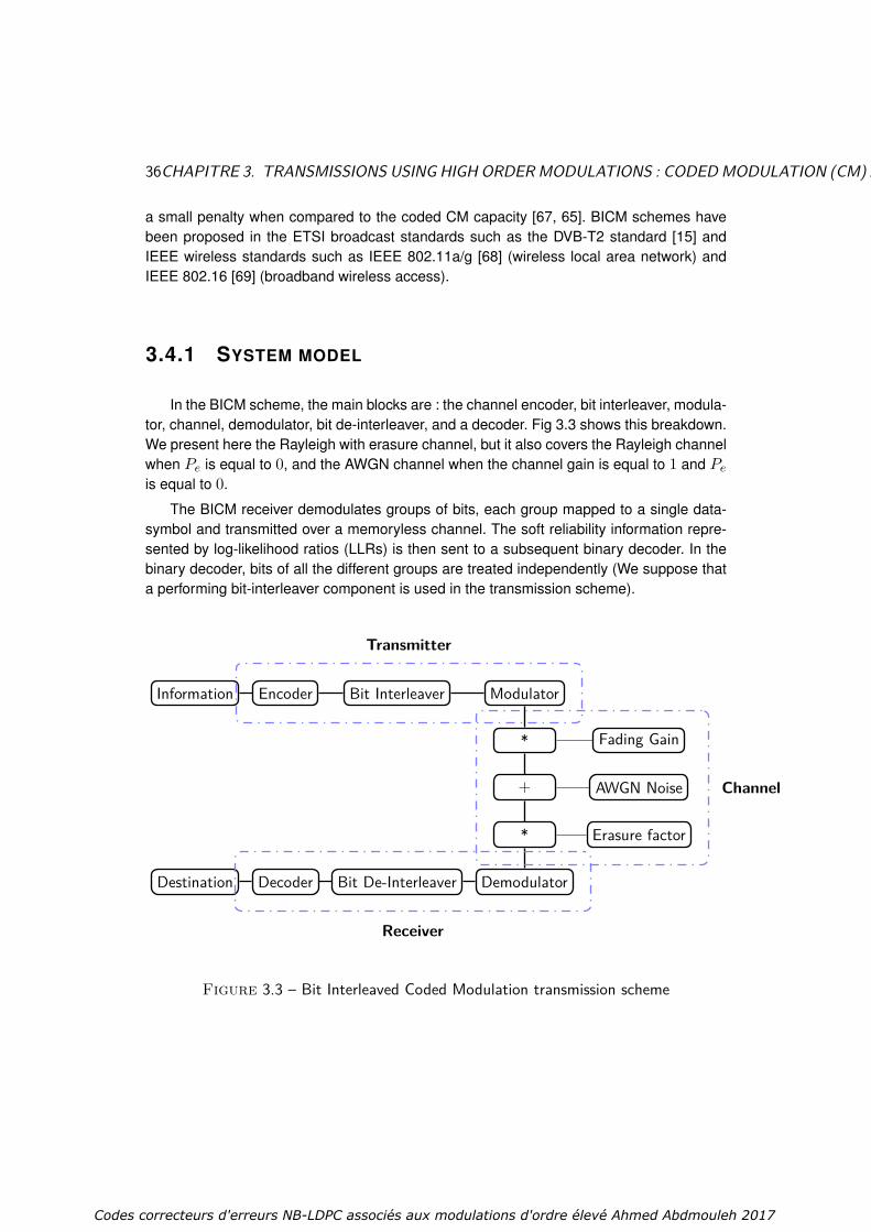
36CHAPITRE 3. TRANSMISSIONS USING HIGH ORDERMODULATIONS : CODEDMODULATION (CM) AND BIT-INTERLEAVED CODEDMODULATION (BICM) SCHEMES
a small penalty when compared to the coded CM capacity [67, 65]. BICM schemes havebeen proposed in the ETSI broadcast standards such as the DVB-T2 standard [15] andIEEE wireless standards such as IEEE 802.11a/g [68] (wireless local area network) andIEEE 802.16 [69] (broadband wireless access).
3.4.1 SYSTEM MODEL
In the BICM scheme, the main blocks are : the channel encoder, bit interleaver, modula-tor, channel, demodulator, bit de-interleaver, and a decoder. Fig 3.3 shows this breakdown.We present here the Rayleigh with erasure channel, but it also covers the Rayleigh channelwhen Pe is equal to 0, and the AWGN channel when the channel gain is equal to 1 and Peis equal to 0.
The BICM receiver demodulates groups of bits, each group mapped to a single data-symbol and transmitted over a memoryless channel. The soft reliability information repre-sented by log-likelihood ratios (LLRs) is then sent to a subsequent binary decoder. In thebinary decoder, bits of all the different groups are treated independently (We suppose thata performing bit-interleaver component is used in the transmission scheme).
Information Encoder Bit Interleaver Modulator
* Fading Gain
+ AWGN Noise
* Erasure factor
Destination Decoder Bit De-Interleaver Demodulator
Transmitter
Receiver
Channel
Figure 3.3 – Bit Interleaved Coded Modulation transmission scheme
Codes correcteurs d'erreurs NB-LDPC associés aux modulations d'ordre élevé Ahmed Abdmouleh 2017
3.4. BIT INTERLEAVED CODED MODULATION 37
3.4.2 THEORETICAL LIMITS FOR TRANSMISSIONS : MUTUAL IN-FORMATION COMPUTATION
The information-theoretic properties of the BICM were first introduced and studied in[65] under the assumption of an ideal interleaver which guarantees a completely randomprocess. This assumption provided a rigorous background for the independent bit assump-tion and allowed the BICM system to be modeled as a set of independent parallel channelswith binary inputs. The BICM scheme MI is then defined as the sum of MIs of the parallelchannels representing the different bits of the transmitted signal [65, 70].
Let us consider a binary mapping of the constellationM that associates to each pointxk a binary codeword (bk,1, · · · bk,m). Let X0
i be the set of symbols where the ith bit bi isequal to 0 and X1
i the set of symbols where the ith bit bi is equal to 1. Thus,
P (bi = s|y) =∑x∈Xs
i
P (x|y), s = 0, 1. (3.33)
Assuming ideal bit interleaving, which makes the considered channel equivalent to mbinary channels ([41] eq. 14), the second term of (3.22) can be expressed as
H(X|Y) =m∑i=1
H(Bi|Y) (3.34)
where Bi represents the ith binary channel associated to the ith bit and H(Bi|Y) can beexpressed for Gaussian, Rayleigh and Rayleigh with erasure channels, as follows :
GAUSSIAN CHANNEL
H(Bi|Y) = −∫y∈C
p(y)H(bi|y)dy. (3.35)
The entropy H(bi|y; r) is defined as
H(bi|y; r) = −∑s=0,1
P (bi = s|y) log 2P (bi = s|y). (3.36)
RAYLEIGH CHANNEL
H(Bi|Y) = −∫y∈C
p(y)(∫
ρ∈R2H(bi|y; ρ)p(ρ)dρ
)dy. (3.37)
The entropy H(bi|y; ρ) is defined as
Codes correcteurs d'erreurs NB-LDPC associés aux modulations d'ordre élevé Ahmed Abdmouleh 2017

38CHAPITRE 3. TRANSMISSIONS USING HIGH ORDERMODULATIONS : CODEDMODULATION (CM) AND BIT-INTERLEAVED CODEDMODULATION (BICM) SCHEMES
H(bi|y; ρ) = −∑s=0,1
P (bi = s|y; ρ) log 2P (bi = s|y; ρ). (3.38)
RAYLEIGH CHANNEL WITH ERASURE
H(X|Y) = −∫y∈C
p(y)(∫
ρ∈R2
(∫e∈[0...1]2
H(bi|y; ρ; e)p(e)de)p(ρ)dρ
)dy, (3.39)
The entropy H(bi|y; ρ; e) is defined as
H(bi|y; ρ; e) = −∑s=0,1
P (bi = s|y; ρ; e) log 2P (bi = s|y; ρ; e). (3.40)
3.5 CHANNEL CAPACITY
Claude Shannon was the pioneer of the information theory field ; he succeeded to cha-racterize the limits of reliable communication on a transmission channel. Before Shannon,the only way to achieve small error probability over a noisy communication channel wasto reduce the transmitted data rate. Shannon showed that, by coding the information, onecan communicate at any rate strictly lower than the channel capacity with probability errortransmission as small as we desire by means of the right correcting codes errors. Recipro-cally, if the transmission rate is greater of equal to the channel capacity, then the probabilityof transmission error has a non-null lower bound. For every discrete memoryless channel,the channel capacity is the maximum information rate expressed in units of information perchannel use, which can be achieved with a vetu small error probability, and is defined asfollows :
C = maxP(X)
I(X;Y) (3.41)
where the maximization is taken over all the possiblities of P(X), the distribution of thetransmitted constellation.
3.5.1 GAUSSIAN CHANNEL CAPACITY
Let us consider a Gaussian channel with a signal power PE , and an additive Gaussiannoise power PN . As shown in Equation 3.21, when calculating the capacity, the expressionof the second term of I(X;Y), H(Y|X), is computed as follows :
Codes correcteurs d'erreurs NB-LDPC associés aux modulations d'ordre élevé Ahmed Abdmouleh 2017
3.5. CHANNEL CAPACITY 39
H(Y|X) = H(X + N|X) (a)= H(N|X) (b)= H(N) (3.42)
In (a) we used the fact that, conditioned on X, X+N is a known shift of the value of Nwhich does not affect the entropy. In (b), it is obvious that X and N are independent. Thismeans that the information over the channel can be computed as the difference betweenthe received symbol and the noise entropies,
I(Y|X) = H(Y)−H(N) (3.43)
N is a noise with a normal distribution : zero mean and variance N0 = PN , we can getthen the expression of H(N)
H(N) = 12 log(2πePN ) (3.44)
We also know that for a given mean and variance, the distribution that maximizes theentropy is the Gaussian one (See [71] p. 181). Thus, maximizingH(Y) over all distributionsof X gives :
maxF(X)
H(Y) = 12 log2(2πe(PE + PN )) (3.45)
Hence, the information capacity C is given by :
C = maxF(X)
I(X;Y)
= 12 log2(1 + PE
PN)
= 12 log2(1 + SNR)
(3.46)
When using a 2-Dimension constellation, the exact value of the capacity C of a discreteGaussian channel is given by :
C = log2(1 + SNR)bits/s/Hz (3.47)
3.5.2 RAYLEIGH CHANNEL CAPACITY
The basic capacity results developed in the case of the Gaussian channel are nowapplied to analyze the limits of communication over fading channels. Assuming that thetransmission has a constant fading event ρ, conditioned on this realization, the obtainedchannel is equivalent to an AWGN channel with received signal-to-noise ratio |ρ|2SNR. Wecan deduce the capacity of the channel as
Codes correcteurs d'erreurs NB-LDPC associés aux modulations d'ordre élevé Ahmed Abdmouleh 2017

40CHAPITRE 3. TRANSMISSIONS USING HIGH ORDERMODULATIONS : CODEDMODULATION (CM) AND BIT-INTERLEAVED CODEDMODULATION (BICM) SCHEMES
C = 12 log2(1 + |ρ|2SNR) (3.48)
Now we can average over many independent fades of the channel, and a reliable rateof communication of E[1
2 log2(1 + |ρ|2SNR)] can be achieved.
C = E[12 log2(1 + |ρ|2SNR)] (3.49)
When using a 2-dimension constellation, the exact value of the capacity C of the Ray-leigh channel is given by
C = E[log2(1 + |ρ|2SNR)] (3.50)
For a very large block lengthN withN →∞ and a given realization of the fading gainsρ1, ρ2, . . . , ρN, the maximum achievable rate through this interleaved channel is
C = 1N
N∑m=1
log2(1 + |ρm|2SNR) (3.51)
3.6 MUTUAL INFORMATION AND CAPACITY CURVES
Based on the theoretical equations of MI and capacity computation developed in theprevious chapter, we present here some MI and capacity curves, for both AWGN and Ray-leigh channels. The MI is computed based on the Equation 3.22. The first term of theequation can be determined easily by means of the Equation 3.23. The second term ofthe Equation 3.22 is developed in Equation 3.24 (AWGN channel), and can be computedthrough a Monte Carlo simulation as detailed in Algorithm 1. Note that the same algorithmcan be adapted for the Rayleigh channel by simply modifying the channel equation. In re-gards to the channel capacity, defined in Equation 3.41 we can get its expression for theconsidered channels in our dissertation. The curves as a function of the SNR can be easilyderived directly from the expressions in Equation 3.47 and Equation 3.51 respectively, forAWGN and Rayleigh channels.
In Figure 3.4 we can observe MI curves of the most used M-QAM modulations : QPSK,16-QAM, 64-QAM and the 256-QAM modulation when using the AWGN channel model.We plotted besides these MI curves the Shannon limit of the AWGN channel. All curvesare presented as a function of the SNR. Figures (Fig. 3.5) and Fig. (3.6) present the MIobtained for the CM and the BICM schemes respectively for AWGN and Rayleigh channelsfor the 64-QAM modualtion. We observe that the CM curve outperforms the BICM for ratesunder 2
3 (or a spectral efficiency smaller than 4 bit/s/Hz), in other terms more informationcan be transmitted in a case of CM scheme than the BICM one, for the same SNR value.
At this point, we have all the necessary tools to perform MI and channel capacity com-putation for both BICM and CM schemes. In the next section, we will introduce the signal
Codes correcteurs d'erreurs NB-LDPC associés aux modulations d'ordre élevé Ahmed Abdmouleh 2017

3.6. MUTUAL INFORMATION AND CAPACITY CURVES 41
Algorithm 1Initialization step : H = 0.for k = 1 to N doRandomly select a point x of the M-QAM constellationGenerate a sample w of a complex AWGN of variance σ2
The received point y is equal to y = x+ wCompute H(X/y)for i = 1 to q, i.e. for each constellation point do
p(y|xi) = 1√2πσe
− d(y,xi)2
2σ2
where d(y, xi) is the Euclidean distance between y and the xiend forfor i = 1 to q dopi = P (xi|y) = p(y|xi)∑q
k=1 p(y|xi)(xi are equiprobable)
end forH(X/y) = −
∑qi=1 pi log 2(pi)
H = H +H(X|y)end forC = log 2q − H
N
−10 −5 0 5 10 15 20 25 300
1
2
3
4
5
6
7
8
9
10
SNR(dB)
Bits p
er
tra
nsm
issio
n
Shannon limit (AWGN channel)256−QAM
64−QAM
16−QAM
QPSK
Figure 3.4 – MI of M-QAM modulation with Shannon limit for AWGN channel.
Codes correcteurs d'erreurs NB-LDPC associés aux modulations d'ordre élevé Ahmed Abdmouleh 2017

42CHAPITRE 3. TRANSMISSIONS USING HIGH ORDERMODULATIONS : CODEDMODULATION (CM) AND BIT-INTERLEAVED CODEDMODULATION (BICM) SCHEMES
−10 −5 0 5 10 15 20 25 300
1
2
3
4
5
6
7
8
9
10
SNR(dB)
Bits p
er
tra
nsm
issio
n
64−QAM MI with CM
64−QAM MI with BICM
Shannon limit (AWGN channel)
Figure 3.5 – 64-QAM MI under CM and BICM schemes.
−10 −5 0 5 10 15 20 25 300
1
2
3
4
5
6
7
8
9
SNR(dB)
Bits p
er
tra
nsm
issio
n
Shannon limit (Rayleigh channel)
256−QAM
64−QAM
16−QAM
QPSK
Figure 3.6 – MI of M-QAM modulation with Shannon limit for Rayleigh channel.
space diversity technique, its domains of application, and the proposed methods of its op-timization.
Codes correcteurs d'erreurs NB-LDPC associés aux modulations d'ordre élevé Ahmed Abdmouleh 2017
3.7. CONCLUSION 43
3.7 CONCLUSION
In this chapter, we began by recalling some elements of the digital communication in atransmission channel. Then the considered modulations in this thesis were particularly ad-vanced. Next, channel properties like MI, and channel capacity of CM and BICM schemesare introduced, and some of the MI curves are presented. The following chapter is dedica-ted to introduce the first novelty proposed in this dissertation, which is the MI based SSDtechnique optimization. The proposed method aim to select the rotation angle that maxi-mizes the MI. An in-depth study will be carried out to optimize the SSD for both CM andBICM schemes.
Codes correcteurs d'erreurs NB-LDPC associés aux modulations d'ordre élevé Ahmed Abdmouleh 2017

44
Codes correcteurs d'erreurs NB-LDPC associés aux modulations d'ordre élevé Ahmed Abdmouleh 2017

Chapitre 4
Signal Space Diversity optimiza-tion based on the analysis of Mu-tual Information
In new broadcast systems, where fading channels with and without erasures are themost used channel models [54] [15] [17], and where high order signal constellations arebeing considered for transmission, big fading events and erasures can incur heavy lossesin terms of error rate and throughput. These impairments have to be appropriately com-pensated for to enhance system performance. A solution proposed to mitigate the effectof big fade events and erasures is to combine the SSD with error control code [72] [73][74], to achieve high data rates over wireless links. Several studies have been carried outto optimize the use of the SSD in the transmission systems. They revealed that SSD repre-sents a promising technique to improve performance of modern communication systems.Recently the DVB-T2 standard [75] witnessed the incorporation of such technique to satisfythe surge in data rate requirements in new broadcast networks.
In this dissertation, we address the problem of optimizing the signal space diversitytechnique. For this purpose we consider mutual information (MI) which provides an analy-tical framework for constellation rotation optimization. This kind of optimization was consi-dered in different areas of application. In the proposed formulation, we aim to optimizeSSD in terms of MI for the Rayleigh channel with and without erasure. Thus, we will givetwo analytical characterizations of the MI of these two channels for both CM and BICMschemes, which are shown to characterize a wide range of transmission conditions. Themethod that we follow consists in first deriving the MI expression of these considered chan-nels for all possible rotation angles. Then, we select the rotation angle that maximizes theMI for considered diversity technique. For both Rayleigh channel and Rayleigh channel witherasure and CM and BICM schemes, we present a detailed analysis of the optimal rotationangles and their performance depending on the signal to noise ratio. We show that the op-timal rotated constellations significantly outperform conventional constellations and thoseproposed in the literature in terms of MI-based theoretical analysis and performance.
45
Codes correcteurs d'erreurs NB-LDPC associés aux modulations d'ordre élevé Ahmed Abdmouleh 2017

46CHAPITRE 4. SIGNAL SPACE DIVERSITY OPTIMIZATION BASED ON THE ANALYSIS OF MUTUAL INFORMATION
In Section 4.1, we introduce the SSD technique, before presenting some examples ofits application in Section 4.2. In sections 4.3 and 4.4, some methods of optimization areexposed. Then, motivations behind considering the mutual information metric are derailedin Section 4.5. Theoretical study and an explanation of the proposed optimization methodare presented in Section 4.6. Finally, in Section 4.7 we show simulation results to confirmthe predicted results announced by the theoretical study.
4.1 SIGNAL SPACE DIVERSITY
Signal Space Diversity (SSD), defines a diversity technique known as coordinate in-terleaving or modulation diversity. The main idea of the SSD technique is to correlate theIn-phase (I) and the Quadrature (Q) components of the conventional QAM signals using arotation, and then to introduce different fading attenuations to I and Q components by dis-tributing these components on different sub-carriers. SSD was first presented in 1992 [76]and then mentioned again represented in 1996 [77] as a coordinate interleaving schemefor performance improvement over fading channels. In 1998 [78], the same scheme wasintroduced as an improved PSK scheme for fading channels and was generalized in 1998[72] as a signal space diversity scheme. In 2003 [79], it was presented as modulation di-versity scheme for frequency selective channels. In 2008, this technique was adopted forthe first time in a transmission standard (DVB-T2 standard) [15].
In fact, SSD increases the diversity order of the signal set with high order modulations,e.g. QAM constellations [72]. Very high diversity order can be achieved, and this results inan almost Gaussian performance over the fading channel [80]. This modulation diversity isessentially uncoded and enables to add diversity with a limited increase of the transmis-sion system complexity, without any of power nor bandwidth expense. The transmitted bitsare grouped into blocks and directly mapped to the constellation points. This means thatthe coding gain is obtained only with some modulation/demodulation complexity increases.To distinguish from other types of diversity like time, frequency, space and code, here thediversity will be related to modulation. The key point to increase the modulation diversityis to apply a certain rotation to a classical signal constellation that maximizes maximumnumber of distinct components, with independent attenuation events on the two compo-nents. In addition to the fact that SSD does not require bandwidth nor power expansion,such a technique leads to significant performance improvement over conventional radiolink communication systems, see DVB-T2 as an example [50, 81].
To apply the SSD technique over wireless communication systems, we have to com-bine the rotated constellation with independent fading events over the two components ofthe sent signal constellation. The independence of fading channels can be performed bymeans of an interleaver in the transmission part and a De-interleaver in the receiver part.Such type of diversity tries to exploit the low probability that deep fades occurrence simul-taneously in both I and Q components. Therefore, SSD offers the possibility to lower theprobability of error. SSD exploits the orthogonality between the I and Q components to
Codes correcteurs d'erreurs NB-LDPC associés aux modulations d'ordre élevé Ahmed Abdmouleh 2017

4.1. SIGNAL SPACE DIVERSITY 47
achieve gain in fading channels with and without erasure. Many techniques have been pro-posed to achieve the independence of the channels required by diversity : Space diversity,antenna polarization diversity, frequency diversity and Time diversity.
The research community showed interest towards the SSD technique and tried to op-timize its application, however certain important questions are not fully answered. Thus,optimizing the SSD technique still has an interesting spectrum of research and developing.Some of these questions include the exact calculation of optimum rotation angles, the ef-fect of different signal constellation mappings, and the influence of the type of transmissionchannel. In the following section we will explain how the SSD technique can be consideredin a transmission channel.
4.1.1 SSD TECHNIQUE DESCRIPTION
In fact, the SSD technique combines a rotated constellation with independent fadingevents over the two components of the sent signal constellation. First, the rotation can beapplied on an M-QAM or M-PSK modulation constellations for example, which is relativelyan easy task. Second, since the two components I and Q are orthogonal, a separationof the two component must be done before transmission. A component interleaver ba-sed on time diversity is practical method to make both components fade independently. Itcan be performed by introducing a delay on the Q component. The constellation symbolX=(xI , xQ) is sent to the receiver via a modulated signal xt = (xtI , xtQ), where t re-presents the time index. Then the quadrature component xtQ is delayed by d time slots.
Thus, at time t, the transmitted symbol (xtI , xt−dQ ) is affected by a multiplicative factor rt
and at time t + d, the transmitted symbol (xt+dI , xtQ) is affected by rt+d. At the receiverside, a delay d on the I component allows the received symbol yt to be reconstructed, withytI = rtIx
tI +wI and ytQ = rtQx
tQ +wQ, where wI and wQ represent the additive noise on
the I and Q axes, rtI = rt and rtQ = rt+d. In [82], the authors propose to make I and Q fadeindependently by means of a random component interleaver, where an efficient componentinterleaver for NB-LDPC scheme on Rayleigh channel is presented.
When using the SSD technique, the transmission scheme elements are almost thesame as for the CM (Fig. 3.2) and BICM (Fig. 3.3) schemes. We have to add in the trans-mitter part, a rotation to the modulator component and, a component interleaver, while forthe receiver part, a component de-interleaver will be considered. Figure 4.1 shows the blockdiagram of a transmission system employing the SSD technique, as described above, ap-plied to a CM scheme. This concept is generic to all constellations, and can be extendedthe BICM scheme by introducing a bit-to-symbol mapper and a bit-to-symbol demapper,respectively, in the transmitter and receiver parts.
Let us consider a constellationM and a symbol X represented with I component xIand Q component xQ. If the transmission of X over the Rayleigh fading channel, is per-formed as described by Figures 3.2 and 3.3, both the I (xI) and Q (xQ) components will
Codes correcteurs d'erreurs NB-LDPC associés aux modulations d'ordre élevé Ahmed Abdmouleh 2017

48CHAPITRE 4. SIGNAL SPACE DIVERSITY OPTIMIZATION BASED ON THE ANALYSIS OF MUTUAL INFORMATION
Informationsource
Encoder α rotationModulator
Componentinterleaver
* Fading Gain
+ AWGNNoise
* Erasurefactor
Destination Decoder DemodulatorComponent
De-interleaver
Transmitter
Receiver
Channel
Figure 4.1 – Coded Modulation transmission scheme with the SSD technique
fade identically. Let us present a frequent scenario when using the Rayleigh channel, asevere fading event on a 16-QAM modulation, without rotation (Figures 4.2 and 4.3). Thereconstructed constellation has points which are very close one to each other. The loss ofinformation on both components is irreversible which increases the decoding error proba-bility. In order to help the demapper to retrieve the transmitted symbol, it is more efficientto send separately xI and xQ in two different times or frequency slots, so that the fadingcoefficient rI affecting xI will be independent of the fading coefficient rQ affecting xQ. Fi-gures 4.4 and 4.5 show the SSD technique effect when a deep fade event occurs on onecomponent. The rotated constellation increases the minimum distance between the pointsof the reconstructed constellation. That offers more protection against the effects of noise,given that the two components will keep a minimum of information. Signal demodulation isassumed to be coherent, so that the fading coefficients can be modeled.
In the next section we provide further details on the SSD technique in order to justifythe performance gain introduced by this technique in both Rayleigh channel and Rayleighchannel with erasure.
Codes correcteurs d'erreurs NB-LDPC associés aux modulations d'ordre élevé Ahmed Abdmouleh 2017

4.1. SIGNAL SPACE DIVERSITY 49
I
Q
Figure 4.2 – 16-QAM modulation(Constellation before transmission)
I
Q
Figure 4.3 – 16-QAM modulation withsevere fading on Q axis
I
Q
Figure 4.4 – Rotated 16-QAM modula-tion (Constellation before transmission)
I
Q
Figure 4.5 – Rotated 16-QAM modu-lation with severe fading on Q axis
4.1.2 INTUITIVE EXPLANATION OF THE SSD TECHNIQUE AD-DED VALUE
The advantages of the SSD are revealed when we apply such a technique to the Ray-leigh channel with and without erasure. For both channels we can propose an intuitiveexplanation of reasons behind its good performing [74]. Here, we will propose a geometri-cal approach to compare the impact of the two scenarios with and without rotation on theminimum Euclidean distance (we assume that I and Q fade independently).
An intuitive explanation for the benefit of the SSD technique under the Rayleigh channelcan be given with reference to figures Fig.4.6 and Fig.4.7 that represent respectively the re-ceived constellation (QPSK modulation) without and with rotation. In such a system with acomponent interleaver, the I and Q components may experience different fading events thatcan be deep or only moderate. Looking on both figures Fig.4.6 and Fig.4.7, the fading ap-plied on the Q component is clearly important. By comparing these two figures, the possible
Codes correcteurs d'erreurs NB-LDPC associés aux modulations d'ordre élevé Ahmed Abdmouleh 2017

50CHAPITRE 4. SIGNAL SPACE DIVERSITY OPTIMIZATION BASED ON THE ANALYSIS OF MUTUAL INFORMATION
added value of rotation becomes evident, we can easily notice that the minimum Euclideandistance d2min in Fig.4.7 is superior than that of Fig.4.6 d1min, which clearly shows thatthe symbol distance increased with rotation. Therefore, the rotation can be intuitively judgedas an advantage for Rayleigh channel, based on an observation of geometrical properties.
I
Q
d1min
Figure 4.6 – QPSK modulation withfading
I
Q
d2min
Figure 4.7 – Rotated QPSK modula-tion with severe fading
A theoretical study of of the impact of rotation on the minimum Euclidean distance canbe performance. Let us consider the received constellation when using a rotated (rotationangle α) and non-rotated constellation (we suppose that rI<rQ). If we consider an M-QAM modulation with a minimum Euclidean distance dmin, for non-rotated constellation theminimum Euclidean distance of the received constellation is d1min = rIdmin. When usinga rotated constellation, the minimum Euclidean distance d2min will be the distance betweenX1 = (rI(cos(α)xI−sin(α)xQ), rQ(sin(α)xI +cos(α)xQ)) andX2 = (rI(cos(α)(xI +dmin)− sin(α)xQ), rQ(sin(α)(xI + dmin) + cos(α)xQ)), it can be computed as follows :
d2min = |X1 −X2|
=√d2min((rIcos(α))2 + (rQsin(α))2)
=√d2min((rIcos(α))2 + (rIsin(α))2) + ζ; ζ > 0
=√d2minr
2I + ζ > dminrI = d1min
(4.1)
Thus, in a theoretical point of view, rotating the constellation will enhance the minimumEuclidean distance of the received constellation.
For Rayleigh channel with erasure, benefit of the SSD technique can be given with re-ference to figures Fig.4.8 and Fig.4.9 that represent respectively the received constellation(QPSK modulation) without and with rotation. When Pe is low the probability of getting bothcomponents erased on the received part is then of the order of the square of Pe, so thatin most cases at least one of the two components reaches the receiver part with only a
Codes correcteurs d'erreurs NB-LDPC associés aux modulations d'ordre élevé Ahmed Abdmouleh 2017

4.2. EXAMPLES OF APPLICATION OF THE SSD 51
I
Q
Figure 4.8 – QPSK modulation with anerasure on the Q component
I
Q
Figure 4.9 – Rotated QPSK modulationwith an erasure on the Q component
fading event with a known coefficient. We avoid then an irreversible loss of information inthe receiver part. Thus the received information will be carried up on a one dimension vec-tor as we can see on the two figures above. By comparing these two figures, the possibleadded value of rotation becomes clearer. We can observe that, in Fig.4.8, the projections ofconstellation points having the same I component are superposed. Thus the minimal dis-tance become equal to 0. That induces disruptions on the decoding process. While whenadding rotation, the image of the received constellation, shown in Fig.4.9, has dissociatedprojections on the I axis. We can clearly notice that the symbol minimum distance increasesunder rotation. Therefore rotation associated with a component interleaver, can be judgedto be advantageous under the Rayleigh channel with erasure.
4.2 EXAMPLES OF APPLICATION OF THE SSD
We can find several studies in the state-of-the-art, that tries to get out advantages ofthe SSD technique application [74] [83] [84]. These applications consider in especially the2-dimension transmission using the Rayleigh channel model with and without erasure [74][50] [81], but d-dimension transmission (d > 2) were also considered like the multiplicativefading channel and the MIMO (multiple input multiple output) channel.
Two-dimension transmission under the Rayleigh channel model with and wi-thout erasure : The two dimension (2-D) transmission over a Rayleigh channel is knownto be a common scheme in the communication systems, [85] [86]. The DVB-T2 standardis an example of industrial application that employs the SSD technique over a 2-D channelwith QAM modulation. SSD enables important gains compared to conventional QAM modu-lation under severe channel conditions. Rotation angles for the different QAM constellationswere proposed and a corresponding low-complexity detection method, and more than 1-dBgain was observed in high rate transmission [15]. However, the corresponding demodula-tion complexity remains an optimization issue [87]. An extension was made for the Rayleighchannel with erasure [50], where more than 6 dB gain can be obtained (Erasure probability
Codes correcteurs d'erreurs NB-LDPC associés aux modulations d'ordre élevé Ahmed Abdmouleh 2017

52CHAPITRE 4. SIGNAL SPACE DIVERSITY OPTIMIZATION BASED ON THE ANALYSIS OF MUTUAL INFORMATION
of 15%, coding rate 4/5 and 16-QAM modulation).
Multiplicative Fading Channels : In [83] the authors generalize the application ofSSD over multiplicative fading channels, where fading is represented by the product of sta-tistically independent Nakagami-random variables. Based on the pairwise error probability(PEP) expression in [83], it is shown that for large dimensions, the error performance overmultiplicative fading channels can be significantly improved by using the SSD technique,without any bandwidth expansion. Such a fading model matches very well with the forestenvironment, in keyhole propagation, or in a propagation in the presence of diffraction streetcorners.
MIMO channel : In [84] an efficient wireless transmission scheme with SSD is pro-posed to improve the MIMO systems reliability in fading channels and to reduce transmis-sion energy. In fact, by introducing the SSD, the proposed scheme optimizes modulationand MIMO, and can enhance the whole transmission performance. Rotation angles for thedifferent QAM modulation signals are proposed for the MIMO scheme in [84]. So, the pro-posed scheme is more efficient, and promising for future wireless communication systems.
4.3 OPTIMIZATION OF THE SSD ROTATION ANGLE
The SSD is a simple combination of a component interleaver and a rotated constella-tion, where the rotation angle is the unique determinant parameter. Therefore, the outcomeof the SSD technique depends directly on the angle α [81, 50]. An efficient choice of therotation angle becomes an important task to achieve. Several studies were performed to im-prove the SSD technique. As the choice of the SSD rotation angle α depends on differentfactors, different solutions have been considered in the literature. In [72] the choice of αaims to maximize the product distance in order to minimize the pairwise error probabilitybetween two different transmitted sequences. Other criteria are considered in [81] like themean Hamming distance between adjacent constellation symbols in the 2-D constellationand the incidence on the Gray mapping in the projected constellation points after rotation.
A review of the literature related to the choice of the rotation angle is presented.
4.3.1 BER-BASED ROTATION ANGLE SELECTION
Here, the main idea consists in visualizing the effect of the constellation rotation, whenusing non-binary LDPC codes and a fixed SNR, on the BER performance. Fig. 4.10 showsthe BER as a function of various rotation angles for a 16-QAM modulation at SNR = 12.8dB, for Rayleigh channel and under the DVB-T standard conditions [88]. The simulationshows that the best performance is obtained at 22.5 for Gray mapped constellation.
Codes correcteurs d'erreurs NB-LDPC associés aux modulations d'ordre élevé Ahmed Abdmouleh 2017

4.3. OPTIMIZATION OF THE SSD ROTATION ANGLE 53
Figure 4.10 – BER performance of the proposed solution systems with different labelingover different rotation angles at SNR=12.8 dB, Rayleigh channel.
4.3.2 UNCODED SER UPPER BOUND APPROACH TO PERFORMTHE ANGLE SELECTION
In [89], the SSD technique was combined with Alamouti coding [90]. It helped to achievemore diversity gain in fading channels. The main idea to select the best rotation angle re-lies on the minimization of uncoded SER. In [89], the authors derived the expression of theupper bound of the uncoded SER over Rayleigh fading channels. To perform such a com-putation, the authors have used the Gaussian distribution formula after the application ofthe Alamouti decoding. A numerical evaluation was performed for different M-QAM modu-lations, to compute the Upper bound of SER for different rotation angles. Such a numericalevaluation with a low computational complexity offers the possibility to test different channelconditions. Figure 4.11 shows the SER for 16-QAM combined with SSD as a function ofthe rotation angle for given values of SNR. For the 16-QAM modulation, by increasing thenumber of receive antennas, the optimal angle at which the SER is minimum is locatedapproximately between 35 and 45.
Codes correcteurs d'erreurs NB-LDPC associés aux modulations d'ordre élevé Ahmed Abdmouleh 2017
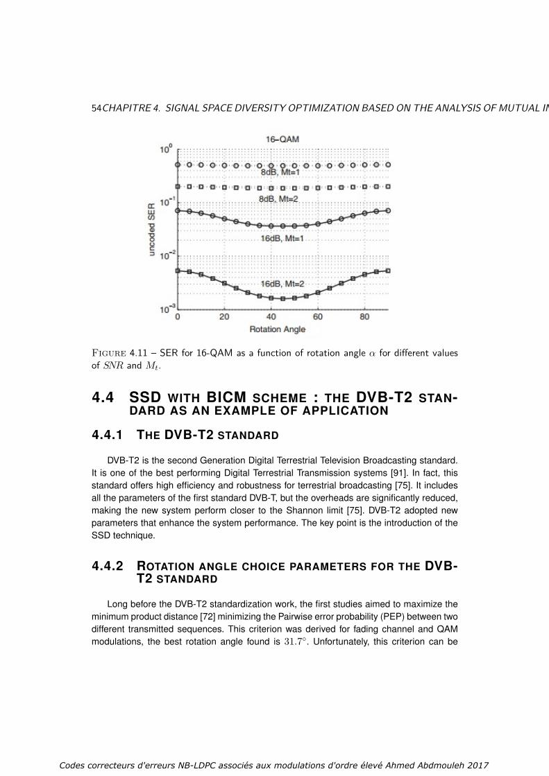
54CHAPITRE 4. SIGNAL SPACE DIVERSITY OPTIMIZATION BASED ON THE ANALYSIS OF MUTUAL INFORMATION
Figure 4.11 – SER for 16-QAM as a function of rotation angle α for different valuesof SNR and Mt.
4.4 SSD WITH BICM SCHEME : THE DVB-T2 STAN-DARD AS AN EXAMPLE OF APPLICATION
4.4.1 THE DVB-T2 STANDARD
DVB-T2 is the second Generation Digital Terrestrial Television Broadcasting standard.It is one of the best performing Digital Terrestrial Transmission systems [91]. In fact, thisstandard offers high efficiency and robustness for terrestrial broadcasting [75]. It includesall the parameters of the first standard DVB-T, but the overheads are significantly reduced,making the new system perform closer to the Shannon limit [75]. DVB-T2 adopted newparameters that enhance the system performance. The key point is the introduction of theSSD technique.
4.4.2 ROTATION ANGLE CHOICE PARAMETERS FOR THE DVB-T2 STANDARD
Long before the DVB-T2 standardization work, the first studies aimed to maximize theminimum product distance [72] minimizing the Pairwise error probability (PEP) between twodifferent transmitted sequences. This criterion was derived for fading channel and QAMmodulations, the best rotation angle found is 31.7. Unfortunately, this criterion can be
Codes correcteurs d'erreurs NB-LDPC associés aux modulations d'ordre élevé Ahmed Abdmouleh 2017

4.4. SSDWITH BICM SCHEME : THE DVB-T2 STANDARD AS AN EXAMPLE OF APPLICATION55
considered just for the asymptotical performance, that is for high SNR values. In practice,actual operating SNRs are not in the high SNR regions, especially when we use performingFEC coding and low rate codes are considered. Therefore, it is obvious that the productdistance criterion is insufficient for the SNR region of interest in DVB-T2 and other criteriaare needed to determine the optimal rotation angle [50]. Moreover, constellation signalswith erasure, the distances between the constellation points have to be measured on theprojection axis I or Q. Thus, a new criterion based on a one-dimensional (1-D) distance isintroduced. To resume, a well-chosen angle should tries to combine the advantages of theangles designed for both fading and erasure channels. The choice of the rotation angle hasto deal with the different criterion that ameliorates transmission over fading channels withand without erasure events. In order to satisfy this goal, the following design criteria haveto be considered :
Angle in degrees
bits
0 5 10 15 20 25 30 35 40 450
1
2
3
AHDHD1DM1DMPD
Figure 4.12 – DVB-T2 standard rotation angle choice parameters : 16-QAM modula-tion
The minimum product distance (MPD) : This 2-D distance has to be maximized inorder to minimize the asymptotical BER at the output of the demapper over fading channelswithout erasures.
The average Hamming distance (AHD) between any two adjacent constella-tion symbols : This is related to the Hamming distance obtained using a certain mapping.This criterion is important especially in the presence of erasures. In fact, when one of thetwo components is erased, the received constellation (which is a 1-D constellation) maylose its Gray mapping. The rotation angle impacts the Hamming distance between adja-
Codes correcteurs d'erreurs NB-LDPC associés aux modulations d'ordre élevé Ahmed Abdmouleh 2017

56CHAPITRE 4. SIGNAL SPACE DIVERSITY OPTIMIZATION BASED ON THE ANALYSIS OF MUTUAL INFORMATION
Constellation Rotation Angle α value (degree)QPSK 29.016-QAM 16.864-QAM 8.6256-QAM 3.6
Table 4.1 – Values of the rotation angles in the DVB-T2 standard
cent projected points varies. When the demapper is in error, the wrong symbol is chosenand respectively its projection. Since the mapping is different from a Gray mapping, thelarge average number of binary errors will increase.
The minimum 1-D Distance (M1D) : In order to minimize the asymptotical BERat the output of the demapper in the presence of erasures, 1-D minimum distance must bemaximized.
The Hamming distance between any two adjacent constellation symbols onthe projected 1-Dimension axes (HD1D) : For high SNR regions the minimum dis-tance the 1-D dominates error events, the constellation have to be chosen to improve theBER at the output of the demapper in this region of interest.
All these criteria were considered to choose the most suitable rotation angle for theDVB-T2 standard for fading channels with and without erasures. Unfortunately, these cri-teria are in conflict, each one leads to different values of the angle. Thus, a compromiseis inevitable. Figure 4.12 shows a graphical representation of the distance measures as afunction of the rotation angle in the case of 16-QAM. The results span only up to 45 due tosymmetry. In the DVB-T2 standard, [15] the angle 16.8 is selected to be a good compro-mise angle. The angle values adopted in the DVB-T2 standard [15] represent a compromisebetween the listed criteria. They are given in Table-4.1 for different modulation orders.
4.5 MUTUAL INFORMATION : METRIC FOR PERFORMANCEENHANCEMENT
In our dissertation, we propose a MI-based optimization of the SSD technique. Theo-retically, MI is known to quantify the amount of information obtained in a communicationsystem, which represents a fundamental notion in information theory. From a practical pointof view, MI was considered as a very efficient metric, and it was a good indicator to targetbetter performance in different areas of application [92] [93]. Different studies have beenperformed to optimize MI of several transmission channel models, specifically in the contextof wireless transmissions.
This MI is an interesting performance metric for systems that employ codes with harddecision decoding, like Reed Solomon codes [92]. MI is also relevant for soft-decoding.It gives an upper bound on the achievable rate for any decoder [94], and is particularly
Codes correcteurs d'erreurs NB-LDPC associés aux modulations d'ordre élevé Ahmed Abdmouleh 2017
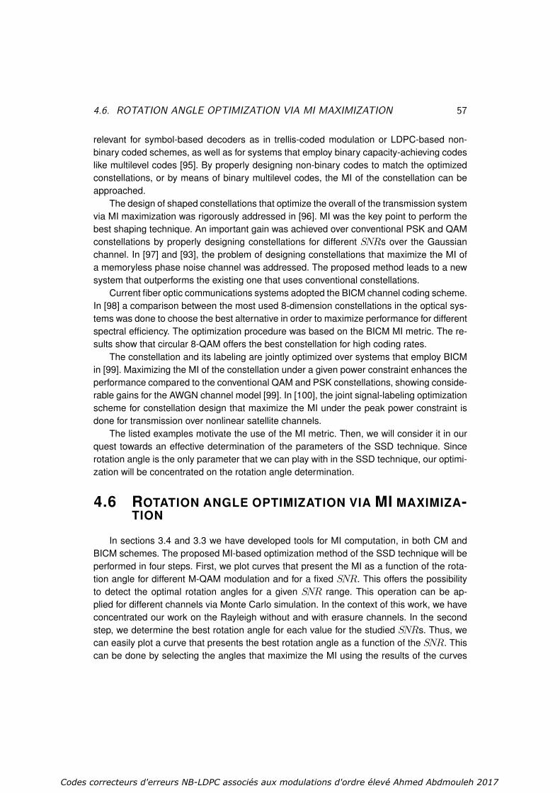
4.6. ROTATION ANGLE OPTIMIZATION VIA MI MAXIMIZATION 57
relevant for symbol-based decoders as in trellis-coded modulation or LDPC-based non-binary coded schemes, as well as for systems that employ binary capacity-achieving codeslike multilevel codes [95]. By properly designing non-binary codes to match the optimizedconstellations, or by means of binary multilevel codes, the MI of the constellation can beapproached.
The design of shaped constellations that optimize the overall of the transmission systemvia MI maximization was rigorously addressed in [96]. MI was the key point to perform thebest shaping technique. An important gain was achieved over conventional PSK and QAMconstellations by properly designing constellations for different SNRs over the Gaussianchannel. In [97] and [93], the problem of designing constellations that maximize the MI ofa memoryless phase noise channel was addressed. The proposed method leads to a newsystem that outperforms the existing one that uses conventional constellations.
Current fiber optic communications systems adopted the BICM channel coding scheme.In [98] a comparison between the most used 8-dimension constellations in the optical sys-tems was done to choose the best alternative in order to maximize performance for differentspectral efficiency. The optimization procedure was based on the BICM MI metric. The re-sults show that circular 8-QAM offers the best constellation for high coding rates.
The constellation and its labeling are jointly optimized over systems that employ BICMin [99]. Maximizing the MI of the constellation under a given power constraint enhances theperformance compared to the conventional QAM and PSK constellations, showing conside-rable gains for the AWGN channel model [99]. In [100], the joint signal-labeling optimizationscheme for constellation design that maximize the MI under the peak power constraint isdone for transmission over nonlinear satellite channels.
The listed examples motivate the use of the MI metric. Then, we will consider it in ourquest towards an effective determination of the parameters of the SSD technique. Sincerotation angle is the only parameter that we can play with in the SSD technique, our optimi-zation will be concentrated on the rotation angle determination.
4.6 ROTATION ANGLE OPTIMIZATION VIA MI MAXIMIZA-TION
In sections 3.4 and 3.3 we have developed tools for MI computation, in both CM andBICM schemes. The proposed MI-based optimization method of the SSD technique will beperformed in four steps. First, we plot curves that present the MI as a function of the rota-tion angle for different M-QAM modulation and for a fixed SNR. This offers the possibilityto detect the optimal rotation angles for a given SNR range. This operation can be ap-plied for different channels via Monte Carlo simulation. In the context of this work, we haveconcentrated our work on the Rayleigh without and with erasure channels. In the secondstep, we determine the best rotation angle for each value for the studied SNRs. Thus, wecan easily plot a curve that presents the best rotation angle as a function of the SNR. Thiscan be done by selecting the angles that maximize the MI using the results of the curves
Codes correcteurs d'erreurs NB-LDPC associés aux modulations d'ordre élevé Ahmed Abdmouleh 2017
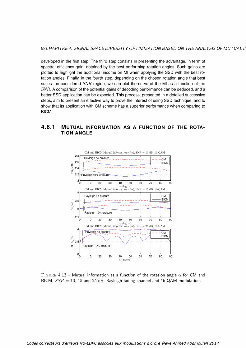
58CHAPITRE 4. SIGNAL SPACE DIVERSITY OPTIMIZATION BASED ON THE ANALYSIS OF MUTUAL INFORMATION
developed in the first step. The third step consists in presenting the advantage, in term ofspectral efficiency gain, obtained by the best performing rotation angles. Such gains areplotted to highlight the additional income on MI when applying the SSD with the best ro-tation angles. Finally, in the fourth step, depending on the chosen rotation angle that bestsuites the considered SNR region, we can plot the curve of the MI as a function of theSNR. A comparison of the potential gains of decoding performance can be deduced, and abetter SSD application can be expected. This process, presented in a detailed successivesteps, aim to present an effective way to prove the interest of using SSD technique, and toshow that its application with CM scheme has a superior performance when comparing toBICM.
4.6.1 MUTUAL INFORMATION AS A FUNCTION OF THE ROTA-TION ANGLE
0 10 20 30 40 50 60 70 80 902
2.2
2.4
2.6
2.8CM and BICM Mutual information=f(α), SNR = 10 dB, 16-QAM
α (degree)
Bit/s/Hz
CM
BICM
0 10 20 30 40 50 60 70 80 902.5
3
3.5
4CM and BICM Mutual information=f(α), SNR = 15 dB, 16-QAM
α (degree)
Bit/s/Hz
CM
BICM
0 10 20 30 40 50 60 70 80 903
3.5
4CM and BICM Mutual information=f(α), SNR = 25 dB, 16-QAM
α (degree)
Bit/s/Hz
CM
BICM
Rayleigh no erasure
Rayleigh 10% erasure
Rayleigh no erasure
Rayleigh no erasure
Rayleigh 10% erasure
Rayleigh 10% erasure
Figure 4.13 – Mutual information as a function of the rotation angle α for CM andBICM. SNR = 10, 15 and 25 dB. Rayleigh fading channel and 16-QAM modulation.
Codes correcteurs d'erreurs NB-LDPC associés aux modulations d'ordre élevé Ahmed Abdmouleh 2017

4.6. ROTATION ANGLE OPTIMIZATION VIA MI MAXIMIZATION 59
0 10 20 30 40 50 60 70 80 903
3.5
4
4.5CM and BICM Mutual information=f(α), SNR = 15 dB, 256-QAM
α (degree)
Bit/s/Hz
CM
BICM
0 10 20 30 40 50 60 70 80 905
5.5
6
6.5
7CM and BICM Mutual information=f(α), SNR = 25 dB, 256-QAM
α (degree)
Bit/s/Hz
CM
BICM
0 10 20 30 40 50 60 70 80 906
6.5
7
7.5
8CM and BICM Mutual information=f(α), SNR = 30 dB, 256-QAM
α (degree)
Bit/s/Hz
CM
BICM
Rayleigh no erasure
Rayleigh 10% erasure
Rayleigh no erasure
Rayleigh no erasure
Rayleigh 10% erasure
Rayleigh 10% erasure
Figure 4.14 – Mutual information as a function of the rotation angle α for CM andBICM schemes. SNR = 15, 25 and 30 dB. Rayleigh fading channel and 256-QAMmodulation.
Our goal is to clarify the influence of the rotation angle of the SSD technique, on theMI metric. Thus, we can simply present the MI curves as a function of the SSD rotationangle for both CM and BICM schemes (i.e the SNR value is then fixed). Fig.4.13 andFig.4.14 show the MI curves as a function of the SSD rotation angle respectively for 16-QAM and 256-QAM modulations. Fig.4.15 and Fig.4.16 represent similar curves for the 64-QAM modulation with a focus on the erasure ratio. We defineMICMSNR(α) andMIBICMSNR (α)as the functions that return the MI value when using α as a rotation angle respectively forCM and BICM, for a fixed SNR value. These functions MICMSNR(α) and MIBICMSNR (α) canbe expressed as :
MICMSNR(α) = ICM (X;Y;α) (4.2)
MIBICMSNR (α) = IBICM (X;Y;α) (4.3)
where ICM (X;Y;α) and IBICM (X;Y;α) are the MI values of a channel scheme that
Codes correcteurs d'erreurs NB-LDPC associés aux modulations d'ordre élevé Ahmed Abdmouleh 2017

60CHAPITRE 4. SIGNAL SPACE DIVERSITY OPTIMIZATION BASED ON THE ANALYSIS OF MUTUAL INFORMATION
apply the SSD with a rotation angle equal to α, respectively for CM and BICM schemes.We can derive their expression from the MI expression I(X;Y) developed in section 3.3.3.3for the CM scheme, and in section 3.4.2 for the BICM scheme. The only change we have tomake in the MI computation is in the equation (Eq. 3.27) where P (y|xl) can be expressedas :
P (y|xl) = 1√2πσ
e−(yrI−rIx
rI
)2+(yrQ−rQx
rQ
)2
2σ2 . (4.4)
with (xrI ,xrQ) the coordinates of the transmitted constellation point after the rotation applied
on the point with (xI ,xQ) as coordinates. The coordinates (yrI ,yrQ) are the image of (yI ,yQ)knowing the rotation angle and the fading events rI and rQ applied respectively on the Iand Q components. We can derive their expression as follows :(
xrIxrQ
)=(cos(α) −sin(α)sin(α) cos(α)
) (xIxQ
)(4.5)
(yrIyrQ
)=(rI rQ
) (cos(α) −sin(α)sin(α) cos(α)
) (yIyQ
)(4.6)
0 10 20 30 40 50 60 70 80 902
2.5
3
3.5
4
4.5CM and BICM Mutual information=f(α), SNR = 15 dB, 64-QAM
α (degree)
Bit/s/Hz
CM
BICM
Rayleigh 10% erasure
Rayleigh 20% erasure
Rayleigh 30% erasure
Rayleigh no erasure
Figure 4.15 – Mutual information as a function of the rotation angle α for CM andBICM. Rayleigh channel and Rayleigh channel with erasure (Pe ∈ 0.1, 0.2, 0.3). SNR= 15 dB and 64-QAM modulation.
Fig. 4.13 considers a 16-QAM with SNR values of 10, 15 and 25 dB. Fig. 4.14 consi-ders a 256-QAM with the same values of SNR. Both figures show results for the Rayleigh
Codes correcteurs d'erreurs NB-LDPC associés aux modulations d'ordre élevé Ahmed Abdmouleh 2017

4.6. ROTATION ANGLE OPTIMIZATION VIA MI MAXIMIZATION 61
0 10 20 30 40 50 60 70 80 903
3.5
4
4.5
5
5.5
6CM and BICM Mutual information=f(α), SNR = 25 dB, 64-QAM
α (degree)
Bit/s/Hz
CM
BICM
Rayleigh no erasure
Rayleigh 10% erasure
Rayleigh 20% erasure
Rayleigh 30% erasure
Figure 4.16 – Mutual information as a function of the rotation angle α for CM andBICM. Rayleigh channel and Rayleigh channel with erasure (Pe ∈ 0.1, 0.2, 0.3). SNR= 25 dB and 64-QAM modulation.
fading channel with erasures (Pe = 0.1) and without erasure. In order to perform perfor-mance comparison between the CM and BCIM schemes, we present the MI curves of bothschemes in one figure to make the comparison clearer. Note that, for the BICM scheme,the Gray mapping of DVB-T2 [15] is used. Gray mapping maximizes performance overthe BICM scheme if no iterative decoding is used. Therefore, the comparison with the CMscheme is fair.
From these curves we can derive several conclusions. First, the rotation angle α thatmaximizes the MI depends on the used SNR, for both CM and BICM schemes. Second,rotation always provides gain for the CM scheme while for the BICM rate loss may appearfor the same rotation angle. Third, for all rotation angles, the CM scheme presents higher MIthan the BICM. The CM curve is always above the BICM one. We can deduce the followingproperties :
1. ∀α,MICMSNR(α) ≥MICMSNR(0)
2. ∃α,MIBICMSNR (α) < MIBICMSNR (0)
3. ∀α,MICMSNR(α) ≥MIBICMSNR (α)
These properties show that the SSD technique is always beneficial for the CM modula-tion scheme. In addition, CM outperforms BICM for almost all spectral efficiencies. We cannotice also that for fixed channel conditions, the rotation angle that maximizes the MI varies
Codes correcteurs d'erreurs NB-LDPC associés aux modulations d'ordre élevé Ahmed Abdmouleh 2017

62CHAPITRE 4. SIGNAL SPACE DIVERSITY OPTIMIZATION BASED ON THE ANALYSIS OF MUTUAL INFORMATION
with the SNR (See Fig. 4.13). An analysis of the dependence between MI and SNR is thenrequired.
To clarify the impact of the erasure factor on the MI when varying the rotation angle, weplot Fig. 4.15 and Fig. 4.16. They present a 64-QAM modulation, with SNR value of 15 and25 dB, respectively. We present the impact of the SSD technique on Rayleigh channel witherasure when using different values of Pe. For these two figures we show curves of MI as afunction of the rotation angle α for CM and BICM schemes, for Rayleigh fading channel witherasures (Pe = 0.1, Pe = 0.2, Pe = 0.3) and without erasure. CM and BICM schemes areconsidered. Then, a comparison between CM and BICM schemes can also be performed.
From curves in Fig. 4.15 and Fig. 4.16, we can observe that the increase in MI is higherin the Rayleigh with erasure channel. MI gain increases with Pe. Thus, the SSD can poten-tially provide more gain in the erasure channel. This conclusion is explained by the increaseof diversity when we apply the SSD technique. If one of the two components vanishes thesecond one can provide information about the received signal. In other terms, each oneof the two components encompasses information about the initial two components beforethe rotation, which make it possible to recover the whole information in the receiver part.We compare the CM and BICM and observe that when Pe increases, CM benefits morefrom the SSD technique. In fact the increase of spectral efficiency is more significant whencomparing to the BICM scheme. We can deduce the following properties :
1. Pe ⇒MICMSNR(α)−MICMSNR(0)2. ∀Pe,∀α,MICMSNR(α) ≥MIBICMSNR (α)An analysis of the MI value as a function of the rotation angle is performed, the next
step aim to evaluate the dependence between the SNR and the best rotation angle that theSSD offers.
4.6.2 BEST ROTATION ANGLE AS A FUNCTION OF THE SNR
Our optimization approach rationalizes the one proposed in [81], which implies a com-plex trade-off with several contradictory criteria. In our case, the MI is the only criterionto choose the rotation angle. Selecting the most performing rotation angle via MI maximi-zation enhance the system performance with the SSD technique. We have shown in theprevious section that for a fixed channel conditions, the best rotation angles varies withthe SNR. Thus, we try to find out a relation between the SSD best rotation angle and thechannel SNR values. For example, from the curves presented in Fig.4.13 and Fig.4.14, wecan easily select the rotation angles that maximizes the MI for all tested SNRs belongingto the sets 10, 15, 25 and 15, 25, 30, respectively. We can generalize the procedure forother SNR values, thus, for each SNR, the optimal rotation angle αCMopt (SNR) for the CMscheme and αBICMopt (SNR) for the BICM scheme can be expressed as follows :
αCMopt (SNR) = argmaxα∈[0−90]
MICMSNR(α). (4.7)
Codes correcteurs d'erreurs NB-LDPC associés aux modulations d'ordre élevé Ahmed Abdmouleh 2017
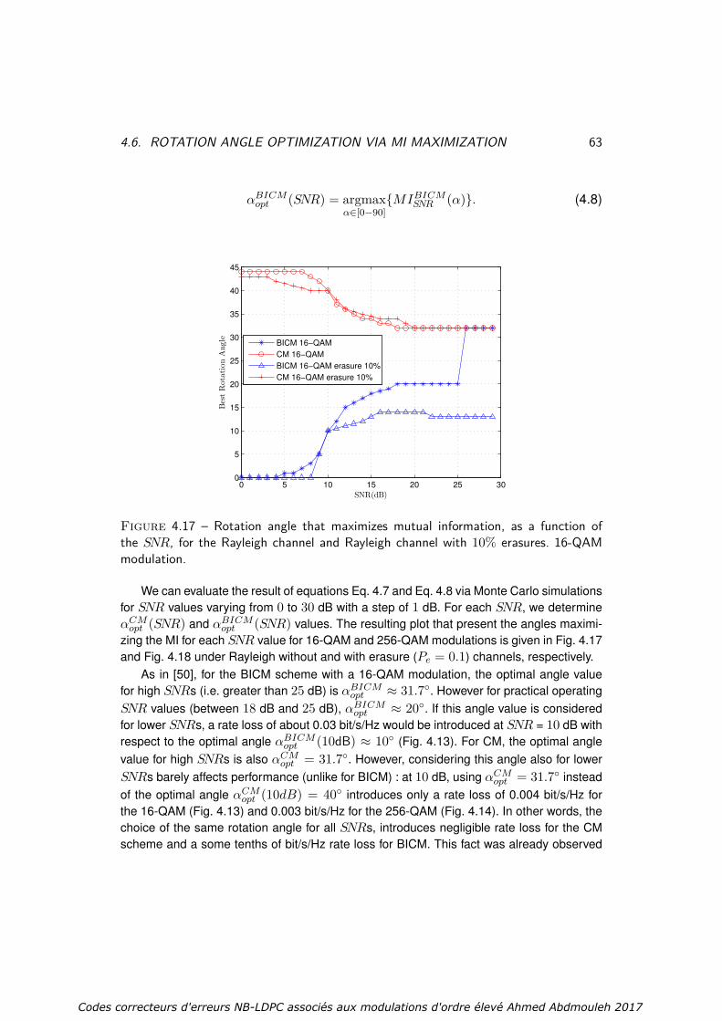
4.6. ROTATION ANGLE OPTIMIZATION VIA MI MAXIMIZATION 63
αBICMopt (SNR) = argmaxα∈[0−90]
MIBICMSNR (α). (4.8)
0 5 10 15 20 25 300
5
10
15
20
25
30
35
40
45
SNR(dB)
BestRotationAngle
BICM 16−QAM
CM 16−QAM
BICM 16−QAM erasure 10%
CM 16−QAM erasure 10%
Figure 4.17 – Rotation angle that maximizes mutual information, as a function ofthe SNR, for the Rayleigh channel and Rayleigh channel with 10% erasures. 16-QAMmodulation.
We can evaluate the result of equations Eq. 4.7 and Eq. 4.8 via Monte Carlo simulationsfor SNR values varying from 0 to 30 dB with a step of 1 dB. For each SNR, we determineαCMopt (SNR) and αBICMopt (SNR) values. The resulting plot that present the angles maximi-zing the MI for each SNR value for 16-QAM and 256-QAM modulations is given in Fig. 4.17and Fig. 4.18 under Rayleigh without and with erasure (Pe = 0.1) channels, respectively.
As in [50], for the BICM scheme with a 16-QAM modulation, the optimal angle valuefor high SNRs (i.e. greater than 25 dB) is αBICMopt ≈ 31.7. However for practical operatingSNR values (between 18 dB and 25 dB), αBICMopt ≈ 20. If this angle value is consideredfor lower SNRs, a rate loss of about 0.03 bit/s/Hz would be introduced at SNR = 10 dB withrespect to the optimal angle αBICMopt (10dB) ≈ 10 (Fig. 4.13). For CM, the optimal anglevalue for high SNRs is also αCMopt = 31.7. However, considering this angle also for lowerSNRs barely affects performance (unlike for BICM) : at 10 dB, using αCMopt = 31.7 insteadof the optimal angle αCMopt (10dB) = 40 introduces only a rate loss of 0.004 bit/s/Hz forthe 16-QAM (Fig. 4.13) and 0.003 bit/s/Hz for the 256-QAM (Fig. 4.14). In other words, thechoice of the same rotation angle for all SNRs, introduces negligible rate loss for the CMscheme and a some tenths of bit/s/Hz rate loss for BICM. This fact was already observed
Codes correcteurs d'erreurs NB-LDPC associés aux modulations d'ordre élevé Ahmed Abdmouleh 2017

64CHAPITRE 4. SIGNAL SPACE DIVERSITY OPTIMIZATION BASED ON THE ANALYSIS OF MUTUAL INFORMATION
0 5 10 15 20 25 300
5
10
15
20
25
30
35
40
45
SNR(dB)
BestRotationAngle
BICM 256−QAM
CM 256−QAM
BICM 256−QAM erasure 10%
CM 256−QAM erasure 10%
Figure 4.18 – Rotation angle that maximizes mutual information, as a function ofthe SNR, for the Rayleigh channel and Rayleigh channel with 10% erasures. 256-QAMmodulation.
in Fig. 4.13 and Fig. 4.14, where the MI in the CM scheme is much less sensitive (about afactor of 10) to the angle variation than in BICM.
In order to clear up the effect of the choice of the SSD rotation angle on CM and BICMschemes for a fixed SNR, we present MI variations between rotation angles 0 and αoptin tables Tab. 4.2 and Tab. 4.3 for 16-QAM and 256-QAM modulations. We consider anSNR value of 10 dB for the 16-QAM modulation and 25 dB for the 256-QAM modulation,respectively. From the two tables we compare the gap ∆ betweenMI0 (α= 0) andMIopt(α = αopt). The results show an advantage for CM of 0.06 dB in Tab. 4.2 and of 0.12 dBin Tab. 4.3. That confirms the superiority of the MI performance that brings SSD to CM,comparing to their binary counterparts BICM.
MI0 αopt MIopt ∆CM 2.60 40 2.68 0.08BICM 2.58 10 2.60 0.02
∆ 0.02 0.08 0.06
Table 4.2 – Mutual information for CM and BICM. SNR = 10 dB. Rayleigh fadingchannel and 16-QAM.
In Fig. 4.19, the angles that maximize the MI for each SNR value (SNR ∈ [0 . . . 30] dB),are presented with different erasure factors for the 64-QAM modulation. We aim to find out
Codes correcteurs d'erreurs NB-LDPC associés aux modulations d'ordre élevé Ahmed Abdmouleh 2017

4.6. ROTATION ANGLE OPTIMIZATION VIA MI MAXIMIZATION 65
0 5 10 15 20 25 300
5
10
15
20
25
30
35
40
45
SNR(dB)
BestRotationAngle
64−QAM
64−QAM 10% erasure
64−QAM 20% erasure
64−QAM 30% erasure
BICM
CM
Figure 4.19 – Rotation angle that maximizes mutual information, as a function of theSNR, for the Rayleigh channel and Rayleigh channel with 10%, 20% and 30% erasures.64-QAM modulation.
MI0 αopt MIopt ∆CM 6.75 31 6.88 0.13BICM 6.75 8 6.76 0.01
∆ 0 0.12 0.12
Table 4.3 – Mutual information for CM and BICM in bit/s/Hz. SNR = 25 dB. Rayleighfading channel and 256-QAM.
the effect of the SSD technique depending of the erasure probability value. Here we showcurves for Rayleigh channel and Rayleigh channel with an erasure probability Pe, with Pe∈ 0.1, 0.2, 0.3. From Fig. 4.19, we can see that the best rotation angles for CM barelyvaries when Pe increases. αCMopt remains almost constant for Rayleigh channel with andwithout erasure, while for BICM the value of αBICMopt differs when using different erasurefactors (see Fig. 4.19) in the transmission channel. The same conclusion can be derivedwith reference to Fig. 4.17 and Fig. 4.18.
From a practical point of view, for the broadcasting applications where each receiverexperiments a different level of SNR and erasure, the choice of the rotation angle is alwaysa trade-off for BICM. This is not the case with the CM scheme, where the rotation angleoffers good performance for different channel properties. This fact confirms that SSD fitsbetter with the CM scheme, in terms of performance and rotation angle choice flexibility.
Codes correcteurs d'erreurs NB-LDPC associés aux modulations d'ordre élevé Ahmed Abdmouleh 2017

66CHAPITRE 4. SIGNAL SPACE DIVERSITY OPTIMIZATION BASED ON THE ANALYSIS OF MUTUAL INFORMATION
As a summary, in this section we derived the best rotation angle for SSD and differentchannel parameters. We performed a performance analysis, and a comparative procedurebetween CM and BICM schemes. Next section discusses with more details the gain obtai-ned with SSD.
4.6.3 MUTUAL INFORMATION GAIN PROVIDED BY THE BEST RO-TATION ANGLES
The SSD technique is applied to enhance the spectral efficiency of the transmissionchannel. After presenting the best rotation angle as a function of the SNR, here we willevaluate the MI gain they offer as a function of the SNR, for different M-QAM modulations,M ∈ 16, 64, 256. This expression can be deduced for both CM (MICMgain(SNR)) and BICMschemes (MIBICMgain (SNR)) as follows :
MICMgain(SNR) = MICMSNR(αopt)−MICMSNR(0) (4.9)
MIBICMgain (SNR) = MIBICMSNR (αopt)−MIBICMSNR (0) (4.10)
0 5 10 15 20 25 30−0.05
0
0.05
0.1
0.15
0.2
0.25
0.3
0.35
SNR(dB)
Bit/s/Hz
16−QAM
16−QAM 10% erasure
CM
BICM
Figure 4.20 – Maximum MI gain with SSD, as a function of the SNR, for the Rayleighchannel and Rayleigh channel with 10% erasures. 16-QAM modulation.
Fig. 4.20 and Fig. 4.21 plot the rate gain with SSD when using the optimal rotationangles αCMopt and αBICMopt , with 16-QAM and 256-QAM modulations, respectively. They canbe easily deduced from the curves presented in Fig. 4.17 and Fig. 4.18, using the equations
Codes correcteurs d'erreurs NB-LDPC associés aux modulations d'ordre élevé Ahmed Abdmouleh 2017

4.6. ROTATION ANGLE OPTIMIZATION VIA MI MAXIMIZATION 67
0 5 10 15 20 25 30−0.05
0
0.05
0.1
0.15
0.2
0.25
0.3
SNR(dB)
Bit/s/Hz
256−QAM
256−QAM 10% erasure
CM
BICM
Figure 4.21 – Maximum MI gain with SSD, as a function of the SNR, for the Rayleighchannel and Rayleigh channel with 10% erasures. 256-QAM modulation.
Eq. 4.9 and Eq. 4.10, respectively. These are results developed for the Rayleigh fadingchannel with erasures (Pe = 0.1) and without erasures.
From these curves we can draw several conclusions. First, the gain that SSD offers toCM is always greater than that of BICM. Second, for certain SNR values MICMgain has 0.1more rate that MIBICMgain (e.g. for SNR ∈ [10 . . . 15], with 16-QAM and Rayleigh channeland Rayleigh channel with erasure Pe = 0.1). Third, the gain converge to a strictly positivevalue with Rayleigh with erasure channel. We can deduce the following properties for theRayleigh channel :
1. ∀SNR,MICMgain(SNR) ≥MIBICMgain (SNR)
2. ∀SNR ∈ [10 . . . 15],MICMgain(SNR)−MIBICMgain (SNR) ≈ 0.1 with 16-QAM
3. SNR→∞,MICMgain(SNR)→ 0
4. SNR→∞,MIBICMgain (SNR)→ 0
For Rayleigh channel with a non-zero Pe erasure probability we can conclude in additionthe following properties for any M-QAM modulation :
1. SNR→∞,MICMgain(SNR)→ log2(M) ∗ (Pe − P 2e )
2. SNR→∞,MIBICMgain (SNR)→ log2(M) ∗ (Pe − P 2e )
The last two properties can be demonstrated as follows : when considering a transmis-sion with erasure probability Pe without SSD application, Pe of the transmitted information
Codes correcteurs d'erreurs NB-LDPC associés aux modulations d'ordre élevé Ahmed Abdmouleh 2017

68CHAPITRE 4. SIGNAL SPACE DIVERSITY OPTIMIZATION BASED ON THE ANALYSIS OF MUTUAL INFORMATION
will be lost through the considered transmission system. But, when using SSD, the proba-bility that the whole information is lost (I andQ are erased), will be equal to P 2
e . Thus whenusing and M-QAM modulation the maximum MI increases by log2(M)∗ (Pe−P 2
e ), for bothCM and BICM schemes.
0 5 10 15 20 25 30−0.1
0
0.1
0.2
0.3
0.4
0.5
0.6
SNR(dB)
Bit/s/Hz
64−QAM
64−QAM 10% erasure
64−QAM 20% erasure
64−QAM 30% erasure
CM
BICM
Figure 4.22 – Maximum MI gain with SSD, as a function of the SNR, for the Rayleighchannel and Rayleigh channel with 10%, 20% and 30%, erasures. 256-QAM modulation.
In Fig. 4.22, we present the MI gain of the SSD when using optimal rotation anglesαCMopt and αBICMopt for the 64-QAM modulation (See Fig. 4.19). The results are presentedover Rayleigh channel and Rayleigh channel with erasure, for different Pe values, Pe ∈[0.1, 0.2, 0.3], and SNRs ∈ [0 . . . 30] dB. From (Fig. 4.22), we can notice that the gain ofspectral efficiency increases with Pe. For SNR = 25 dB, MICMgain = 0.25 for Pe = 0.1,while MICMgain = 0.38 for Pe = 0.3, . Unlike BICM, CM takes always advantage of SSDand offers positive MI gain for practical SNRs, SNR ∈ [10 . . . 20] for all different erasureprobabilities Pe. In the next section, as a complement to this analysis, we analyze thecurves representing the MI as a function of the SNR.
4.6.4 MUTUAL INFORMATION AS A FUNCTION OF THE SNR
Let us now consider the curves that present the relation between MI and SNR for theCM and BICM schemes. In fact, to get such curves we have to choose at the beginning afixed rotation angle. We will consider the most appropriate rotation angle for the CM schemewhich is αo = 31.7, this angle choice is a good compromise for high and low SNRs. For the
Codes correcteurs d'erreurs NB-LDPC associés aux modulations d'ordre élevé Ahmed Abdmouleh 2017

4.6. ROTATION ANGLE OPTIMIZATION VIA MI MAXIMIZATION 69
BICM scheme, the angle values will be those adopted in the DVB-T2 standard [15] reportedin Tab. 4.1.
Using the MI equation developed in section 3.3.3.3, and by considering the equationdeveloped in section 4.6.1, we plotted curves in Fig 4.23. We have considered the 16-QAM with rotation angles αo = 31.7 for CM and αo = 16.8 for BICM. The MI curves arepresented for the Rayleigh channel with no erasure and with erasure (Pe = 0.1).
10 12 14 16 18 20 22 24 26 282
2.2
2.4
2.6
2.8
3
3.2
3.4
3.6
3.8
4
SNR(dB)
Bits p
er
transm
issio
n
CM 16−QAM: α = 0°
CM 16−QAM: α = 31.7°
BICM 16−QAM : α = 0°
BICM 16−QAM : α = 16.8°
Shannon limit
Rayleigh no erasure
Rayleigh 10% erasure
Figure 4.23 – CM and BICM mutual information curves for a 16-QAM modulationover fast flat fading Rayleigh channel (without erasures and with 10% erasures)
The same curves are presented for the 256-QAM modulation in Fig. 4.24. The chosenrotation angles are αo = 31.7 for the CM and α = 3.6 for the BICM (see Tab. 4.1). Withthe BICM scheme, the SSD barely changes the MI performance and does not offer anysignificant advantage. However, for the CM scheme, a SNR gain greater than 1 dB can beobserved for spectral efficiencies larger than 7 bit/Hz/s.
From these curves again, we observe that the CM with SSD outperforms the non-rotated scheme for all SNRs. This does not occur for BICM : at low SNR (up to approxima-tely 12 dB for the 16-QAM), the rotation causes a MI loss compared to non-rotated BICM.This can also be observed in Figures 4.13 and 4.14, where the MI curve decreases with ro-tation. Therefore, the gains displayed by the rotated CM are more significant than for BICM.Over the erasure Rayleigh channel (pe = 0.1), the gain introduced with the SSD is moresignificant than the one for the no-erasure case, for both 16- and 256-QAM and especiallyfor high SNR values.
These theoretical studies are performed in order to optimize MI with SSD technique.We proposed MI as a parameterto optimize the SSD technique application. To validate the
Codes correcteurs d'erreurs NB-LDPC associés aux modulations d'ordre élevé Ahmed Abdmouleh 2017
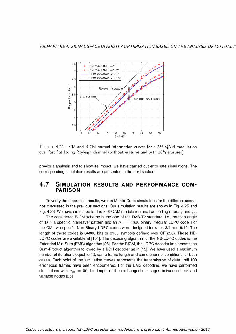
70CHAPITRE 4. SIGNAL SPACE DIVERSITY OPTIMIZATION BASED ON THE ANALYSIS OF MUTUAL INFORMATION
10 12 14 16 18 20 22 24 26 28
3.5
4
4.5
5
5.5
6
6.5
7
7.5
SNR(dB)
Bits p
er
transm
issio
n
CM 256−QAM: α = 0°
CM 256−QAM: α = 31.7°
BICM 256−QAM : α = 0°
BICM 256−QAM : α = 3.6°
Rayleigh 10% erasureShannon limit
Rayleigh no erasure
Figure 4.24 – CM and BICM mutual information curves for a 256-QAM modulationover fast flat fading Rayleigh channel (without erasures and with 10% erasures)
previous analysis and to show its impact, we have carried out error rate simulations. Thecorresponding simulation results are presented in the next section.
4.7 SIMULATION RESULTS AND PERFORMANCE COM-PARISON
To verify the theoretical results, we ran Monte-Carlo simulations for the different scena-rios discussed in the previous sections. Our simulation results are shown in Fig. 4.25 andFig. 4.26. We have simulated for the 256-QAM modulation and two coding rates, 3
4 and 910 .
The considered BICM scheme is the one of the DVB-T2 standard, i.e., rotation angleof 3.6, a specific interleaver pattern and an N = 64800 binary irregular LDPC code. Forthe CM, two specific Non-Binary LDPC codes were designed for rates 3/4 and 9/10. Thelength of these codes is 64800 bits or 8100 symbols defined over GF(256). These NB-LDPC codes are available at [101]. The decoding algorithm of the NB-LDPC codes is theExtended Min-Sum (EMS) algorithm [26]. For the BICM, the LDPC decoder implements theSum-Product algorithm followed by a BCH decoder as in [15]. We have used a maximumnumber of iterations equal to 50, same frame length and same channel conditions for bothcases. Each point of the simulation curves represents the transmission of data until 100erroneous frames have been encountered. For the EMS decoding, we have performedsimulations with nm = 50, i.e. length of the exchanged messages between check andvariable nodes [26].
Codes correcteurs d'erreurs NB-LDPC associés aux modulations d'ordre élevé Ahmed Abdmouleh 2017

4.7. SIMULATION RESULTS AND PERFORMANCE COMPARISON 71
22.5 22.6 22.7 22.8 22.9 23 23.1 23.2 23.3 23.410
−4
10−3
10−2
10−1
100
Es/N
o(dB)
FE
R
FER reg. GF(256), nm=50 α=0°
FER reg. GF(256), nm=50 α=31.7°
FER optimised irreg. GF(2) α=0°
FER optimised irreg. GF(2) α=3.58°
Figure 4.25 – FER simulation for 3/4-rate BICM-GF(2) and CM-GF(256) schemesover the fast flat Rayleigh fading channel, with and without Rotated Constellation
27.2 27.4 27.6 27.8 28 28.2 28.4 28.6 28.8 2910
−3
10−2
10−1
100
Es/N
o(dB)
FE
R
FER reg. GF(256), nm=50 α=0°
FER reg. GF(256), nm=50 α=31.7°
FER optimised irreg. GF(2) α=0°
FER optimised irreg. GF(2) α=3.58°
Figure 4.26 – FER simulation for 9/10-rate BICM-GF(2) and CM-GF(256) schemesover the fast flat Rayleigh fading channel, with and without Rotated Constellation
Fig. 4.25 presents results for a code rate of 3/4. As already observed in Fig. 4.14, theSSD technique introduces performance loss in the BICM scheme for spectral efficiencies
Codes correcteurs d'erreurs NB-LDPC associés aux modulations d'ordre élevé Ahmed Abdmouleh 2017
72CHAPITRE 4. SIGNAL SPACE DIVERSITY OPTIMIZATION BASED ON THE ANALYSIS OF MUTUAL INFORMATION
lower than 7 bit/Hz/s. However, as announced by the theoretical study, a gain of about 0.3dB is provided by the SSD technique for CM. For higher spectral efficiencies (9/10-rate inFig. 4.26), SSD introduces gain for both the BICM and CM schemes (see the right upperzone of Fig. 4.24). This gain is more significant with the CM scheme (1.3 dB at FER = 10−2
compared to about 0.15 dB for BICM). Note that these performance results are consistentwith the analysis of Fig. 4.14.
4.8 CONCLUSION
This chapter investigates the application of the SSD technique to high spectral effi-ciency communications in the context of next generation broadcasting systems. The issuesof combining SSD with CM and BICM schemes is considered under Rayleigh channelswith and without erasures. At the beginning, we have described the principle of the SSDtechnique, and introduced some of its state-of-the-art optimizations. Then, we proposeda new criterion to determine the optimal rotation angle for the SSD technique based onthe MI metric. The rotation angle is the one that maximizes the MI for practical SNR va-lues. For both CM and BICM schemes, with Gray labeled square M-QAM modulations, M ∈16, 64, 256, several interesting properties are obtained, based on which the optimizationwork is presented. We have found that absolute optimal rotation angle does not exist, andthat its value varies with the SNR. For the CM scheme, we can conclude that a constella-tion rotation has always a positive effect on the MI metric, which is not the case for BICMscheme where MI degradation can be seen for some SNR or α values. An evaluation ofthe best rotation angle was then performed, and a study the obtained gain is detailed to fa-cilitate our analysis of the SSD technique. We showed that non-binary CM are more robustthan BICM and take better advantage of the SSD technique. Severe fading and erasureevents in the transmission channels can be mitigated by applying the SSD technique toCM and BICM schemes. This allows for optimized performance in fading channels with andwithout erasure. The solutions that we proposed can lead to significant performance gainsfor next generation broadcasting systems. Simulation results presented performance gainthat reaches 1.3 dB for CM scheme compared to BICM systems with DVB-T2 LDPC codes,with a code rate of 1
3 and a BER of 105.
Codes correcteurs d'erreurs NB-LDPC associés aux modulations d'ordre élevé Ahmed Abdmouleh 2017

Chapitre 5
Joint modulation and coding op-timization with NB-LDPC codes
The joint optimization of binary error code and binary mapping of the constellationpoints is an efficient method to improve the overall performance of a communication sys-tem. For example in the eighties, Ungerboeck proposed in [102] the trellis coded modula-tion, while since the early 2000s, the problem of optimizing the BICM scheme for LDPCcodes [103] studied the dependence between the binary LDPC code matrix and the dif-ferent levels of error protection provided bits in one symbol. To the best of our knowlege,nothing so far has been done about joint optimization of non-binary code and mapping onconstellation points.
This chapter constitute a first attempts to construct an efficient CM scheme in thecontext of high spectral efficiency transmission. In this context, we propose to perform ajoint optimization of both channel coding and modulation, when using the CM scheme. Infact, the dependence between the code symbols and the constellation points leads to re-think about their relation and its impact on the decoding results. Intuitively, we can say thatthe joint optimization of channel coding and modulation can bring additional improvementon the decoding performance. Here we will focus on a case of application involving theassociation of NB-LDPC codes over GF(q) with the QAM modulations of the same cardi-nality q, (e.g. GF(64) and 64-QAM modulation). We will restrict our optimization method tothe joint labeling of the constellation point, with the choice of the coefficients of one parity-check equation. In other words, we will generalize the method proposed by Poulliat et al.[25] that uses the minimum Hamming distance and the multiplicity of a binary code asso-ciated to one parity-check equation coefficients. The former method is efficient for BPSKmodulation where the Hamming distance is proportional to the Euclidean one. This is notthe case for the QAM modulation, thus the Euclidiean distance has to be reconsidered inthe CM scheme design criteria.
In Section 5.1, we will review the construction of a non-binary PCM. We will presentthe key steps to build a NB-LDPC PCM. In general, NB-LDPC PCM construction is realizedin two distinct steps : non-null positions selection and the coefficients choice. In Section
73
Codes correcteurs d'erreurs NB-LDPC associés aux modulations d'ordre élevé Ahmed Abdmouleh 2017

74CHAPITRE 5. JOINTMODULATION AND CODING OPTIMIZATIONWITH NB-LDPC CODES
5.2 we will introduce our motivation behind the proposed method. A study of the Eucli-dean distance and a comparison with the Hamming distance over CM will be presentedrespectively in Section. 5.3 and Section. 5.4. Then, a distance spectrum evaluation for NBcodes will presented in 5.5. The incidence of Gray mapping choice on Euclidean distanceand distance spectrum will be studied in Section. 5.6. In Section 5.7 the joint optimizationof mapping and NB-LDPC matrix coefficient will be explained. We will present the choiceof coefficient and modulation mapping that optimizes the NB-LDPC codes with high ordermodulations decoding performance. Finally simulation results will be presented in Section.5.8
5.1 NB-LDPC CODES CONSTRUCTION
The coding theory domain is mainly characterized by the development of powerful bi-nary error-correcting codes that can be iteratively decoded. Gallager proposed the LDPCcodes with arbitrary alphabet size [13]. Since their rediscovery in [1], LDPC codes areone of the most performing coding techniques for error control in communication and datastorage systems. They offer capacity-approaching performance [104] and practically imple-mentable decoding algorithms. Several research efforts focused on how to design, analy-sis, and decode of these LDPC codes. However, the research efforts devoted to NB-LDPCcodes are far less than those already achieved to their binary counterpart. This lack of en-thusiasm in NB-LDPC codes is due to their decoding complexity which makes them difficultto be implemented on hardware. Based on the experimental results presented by Daveyand MacKay in [22] on LDPC codes built on finite Galois fields, recent works focused onthe analysis and design of NB-LDPC codes on both binary, e.g. BPSK modulation, andnon-binary channels, e.g. M-QAM modulation.
There exist several propositions of NB-LDPC construction in the literature. Construc-tions of NB-LDPC codes have been proposed through the design of the PCM with pres-cribed properties. The design aim to satisfy various criteria like the near-capacity perfor-mance, and efficient encoding and decoding. But, the PCM construction was always dealingwith contradictory parameters. The PCM with high column weight offers a better evaluationof the circulating messages between nodes, while, lower row weights of H decreases thecomputation complexity in check-node processing. This trade-off was an important issue forPCM construction. It was proven in [34, 25] that when q becomes large (q >> 2), the bestperformances are obtained for ultra sparse NB-LDPC codes, which are NB-DPC codes withthe minimum connectivity on the variable nodes dv = 2.
Several methods have been developed to assess the asymptotic performance of NB-LDPC codes. Bennatan and Burshtein studied error correcting performance of NB-LDPCcodes by applying the ML decoding and the BP algorithm [105] and by including the de-velopment of extrinsic information transfer charts for arbitrary channels [106]. Analysis viathe Gaussian approximation was discussed in [107]. The study of the density evolution ofNB-LDPC codes was performed for the erasure channel in [108].
Codes correcteurs d'erreurs NB-LDPC associés aux modulations d'ordre élevé Ahmed Abdmouleh 2017

5.1. NB-LDPC CODES CONSTRUCTION 75
The construction of the PCM of NB-LDPC codes can be performed in two steps thatare generally solved in a sequential manner. First, the positions of the non-null entries ofthe PCM are optimized in order to improve the error floor region [71]. The main idea is tohave good girth properties to minimize the impact of cycles when using the BP algorithmon the associated Tanner graph. This can be efficiently achieved using algorithms like theprogressive edge growth (PEG) algorithm [109], or using Quasi-cyclic matrix as in [110],where efficiently encodable quasi-cyclic NB-LDPC (QC-NB-LDPC) codes were proposed.In the second step, the PCM non-null entries must be carefully chosen to optimize the rowsof the PCM, and then, the whole PCM structure properties to lower the waterfall. They canbe selected either randomly from a uniform distribution among non-null elements of GF(q)[109] or carefully to meet some design criteria, as done in [25]. In [111] the proposed me-thod for NB-LDPC code construction is based on the selection on nearly optimum non-nullentries in the PCM for codes of column weight dv equal to 2. Once non-null coefficientsare chosen to optimize one row in the PCM, they have to be meticulously positioned in thewhole PCM to guarantee good cycle properties in the PCM [25] in order to improve the wa-terfall region and to lower the error floor. Another construction method was proposed in [9]that consist on designing regular NB-LDPC codes over GF(q) via their binary image. Thus,both non-null positions and non-null entries will be determined simultaneously. Poulliat etal. proved in [9] that good waterfall and error floor properties can be obtained.
5.1.1 NON-NULL POSITIONS CHOICE IN THE PCM
The first step of a NB-LDPC construction consists in selecting of the non-null positionsentries on the PCM. They must be meticulously chosen because they lead to the structureof the Tanner graph and its topological properties, such as the number of cycles in theTanner graph associated with the code. It was shown in [25] that short cycles in the Tannergraph result in non-codeword errors. The fundamental issue when we select the non-nullpositions is the presence of cycles that affects negatively the NB-LDPC codes performance.In other words, when using an iterative decoding algorithm with a message passing typealgorithm, cycles lead to self-confirmation of exchanged messages. Short cycles may leadto have certain non-codewords that compete with the transmitted codeword to be the outputof the decoder, which degrade the decoder performance. As cycles impact the decodingerror performance, the positions of the non-null entries of the parity-check matrix need tobe carefully chosen to maximize the minimum size of a cycle in the graph i.e. the girth ofthe code, and to minimize the multiplicity of cycles of minimum sizes of cycles. The goal isto have a small number of short cycles.
In practice, it is not affordable to avoid cycles in the Tanner graph, but it is possible toconstruct the PCM with girths as large as possible, so that the correlation of messagescan be minimized. To fulfill such an objective, we can find several construction techniquesin the literature that claim different advantages. Based on the methods of construction,LDPC codes can be classified into two main categories, random or random-like codes and
Codes correcteurs d'erreurs NB-LDPC associés aux modulations d'ordre élevé Ahmed Abdmouleh 2017

76CHAPITRE 5. JOINTMODULATION AND CODING OPTIMIZATIONWITH NB-LDPC CODES
structured codes. Among these non-null positions selection techniques, we can recall someof the most used algorithms :
Quasi-cyclic NB-LDPC construction : NB-LDPC can be efficiently constructedusing a Quasi-Cyclic structure on the parity-check matrix. The resulting codes are the so-called Quasi Cyclic NB-LDPC (QC-NB-LDPC) codes, considered as an extension of theProtograph LDPC codes [112]. QC-NB-LDPC codes [113] are defined by an m × n inci-dence matrix, known as a protomatrix, with non-negative integer entries aij that correspondto aij parallel edges in the graph. An rm×rnmatrix is obtained by replacing each non-nullentry aij by an aij-shift applied on the identity matrix (circulant matrix) of size r and thezero entry by an r × r zero matrix. The design and optimization of QC-LDPC codes areof great interest to code designers since they offer not only performing decoding resultsbut also an implementation friendly structure. They can be encoded with low complexity bymeans of simple shift registers with linearly complexity [114] and can be efficiently decoded[38, 113]. We can find several high-performance QC-NB-LDPC codes construction proposi-tions [110, 38], and some recent constructions include [115, 116]. However, QC-NB-LDPCcodes have limitations ; some cycles in the protograph matrix cannot be suppressed duringthe extension phase, which give an upper minimum Hamming distance associated to eachprotograph matrix. These results are obtained independently of the size of the circulantmatrix entries [117] ; therefore, an increase in the circulant size matrix does not provide anincrease in minimum distance beyond a certain limit.
Selecting the non-null positions in the PCM is a determinant step in the constructionof NB-LDPC codes. In our dissertation, we will consider the QC-NB-LDPC codes with theminimum connectivity on the symbol nodes, dv = 2. We have made this choice of dv due toits performing performance and low complexity implementation [25]. The edge label choicerepresents another degree of freedom in the design of NB-LDPC code. It will be a matterof study in the following sections.
5.1.2 NB COEFFICIENTS CHOICE IN THE PCM
The second step of a NB-LDPC code construction, consist in the determination of non-null entries values of one rows for the PCM, regardless of the structure of the Tanner graphassociated with it. In other words, the problem of the selection and the matching of thePCM non-null entries is done assuming that the positions of non-null entries in the PCMassociated with the NB-LDPC code have been already optimized. Different methods wereproposed in the state-of-the-art to select the non-null entries of one in a PCM. In [118] thevalues of the non-null entries of the PCM are selected randomly from a uniform distributionamong non-null elements of GF (q). Davey et al. [22] proposed an optimization method tochoose the non-null entries based on the density evolution determination, which is compu-tationally expensive for high order field. In [25], authors optimized the choice of the non-nullentries based on the binary image representation of the PCM by improving the minimumHamming distance of the binary image of the code per row.
Codes correcteurs d'erreurs NB-LDPC associés aux modulations d'ordre élevé Ahmed Abdmouleh 2017

5.2. NB-LDPC CODES ANDMODULATION JOINT OPTIMIZATION : MOTIVATION FACTS77
Efficient choice of non-null entries makes more reliable the exchanged messages alongthe Tanner graph edges. It was proven that optimized row of coefficients to generate thePCM ameliorate performance compared to code with randomly selected coefficients es-pecially for Galois fields GF(q) with q >> 2. In fact, a row optimization, through non-nullentries selection, improves the waterfall region of the decoding performance curves [71].To lower the error floor region, coefficients that belongs to the short length cycles and stop-ping sets must be carefully chosen to avoid low weight code word associated, and then toimprove the minimum distance of the codes [9].
Choosing the non-null entries in the PCM was a subject of research developed speciallyfor binary transmission, thus the proposed optimizations were sufficient to make this stepfulfilled with optimal non-null values. However, when using high spectral efficiency trans-missions, these optimizations may not be enough to make the choice of non-null entriesoptimal. In the chapter, the choice of the non-null entries will take into account the use ofhigh order modulations, (i.e. M-QAM modulation), in the transmission scheme.
5.2 NB-LDPC CODES AND MODULATION JOINT OPTI-MIZATION : MOTIVATION FACTS
In a case of non-binary transmission, were the code and modulation order matches, theN codeword symbols are associated directly to a sequence of N points from the constella-tion. Thus, the symbols can be represented as points in the Euclidean space. The resultingmodulated codeword vector can be seen as a vector of signal points. The distance betweenany two modulated codeword vectors can be determined from the Euclidean distance bet-ween the signal points representing each vector in the Euclidean space. The digital signaluses a modulation mapping (Gray mapping as an example) which associates to each sym-bol a sequence of binary signals. Codeword vectors are mapped onto points in the signalconstellation in a way that enhances the distance properties of the error correcting code.
Binary modulation systems with NB-LDPC codes are optimized for Hamming distance[25]. Soft decision decoding of NB-LDPC codes have been well established for power-efficient transmission at spectral efficiency of 2 bit/sec/Hz. In fact, for binary modulations,e.g. BPSK or QPSK (with Gray mapping) modulations, the Hamming distance of the errorcorrecting code is equivalent to the Euclidean distance of the modulated codeword vectors.Then, the values and the positions of the non-null entries of the PCM can be optimized ina way that maximizes the Hamming distance of the code [25]. For non-binary modulations,the Euclidean distance of modulated codeword vectors is not equivalent to the Hammingdistance of the error correcting code. In addition, the Euclidean distance properties de-pend on the modulation mapping used to map the codeword vectors onto signal points.As a result, the construction of PCM of NB-LDPC codes for coded modulations in orderto maximize the Hamming distance is sub-optimal. This relation between the mapping andthe Euclidean distance for coded modulation is a relevant factor and offers an interestingpossibility to propose better CM scheme. There is accordingly a need for constructing effi-
Codes correcteurs d'erreurs NB-LDPC associés aux modulations d'ordre élevé Ahmed Abdmouleh 2017

78CHAPITRE 5. JOINTMODULATION AND CODING OPTIMIZATIONWITH NB-LDPC CODES
cient non-binary coded modulations involving error correcting codes that are optimized forthe Euclidean distance rather than for the Hamming distance and are jointly optimized withthe modulation mapping.
The main reason behind the development of such an optimization method is the factthat the Euclidean distance properties of the codes depend on the modulation used in thetransmission scheme. This dependence is especially revealed when we consider high ordermodulation. If the Galois Field symbols are affected directly to the constellation points, anypermutation of the constellation point’s positions will impact the Euclidean distance valuesbetween symbols, and consequently will impact also the Euclidean distance between code-words. Thus, a good optimization of should be aware of the modulation and channel codingto enhance the whole transmission systems properties and then the CM performance. Forhigh spectral efficiency transmission, the problem of the adaptation of the non-null entriesof the PCM to a high order modulation was ignored in the literature, for NB-LDPC codes orany other non-binary code.
Two parameters of the CM scheme will be jointly optimized for a better decoding per-formance. The first parameter is the non-null entries of one row in the PCM, and the se-cond one is the mapping of the modulation. These two parameters need to be meticulouslyoptimized together. Two main metrics will be our references in the proposed method op-timization which are the minimum Euclidean distance and the spectrum of the Euclideandistances between codewords. Before proceeding such an optimization method, some toolsneeds to be developed to facilitate the Euclidean distance computation, and the code spec-trum evaluation.
5.3 EUCLIDEAN DISTANCE EVALUATION
To perform an Euclidean distance evaluation between two vectors we need to clarifysome notions. Let us consider two vectors x = (x0, x1 . . . xn−1) and y = (y0, y1 . . . yn−1)of Rn. Their Euclidean distance D(x, y) can be computed as follows :
D(x, y) =
√√√√n−1∑i=0
(xi − yi)2. (5.1)
Assuming that each symbol x in GF(q) is associated with an element of the q-aryconstellationM, we can define the mapping function π as follows :
π : GF(q)→ R2
x→ (πI(x), πQ(x))(5.2)
Where πI(x) and πQ(x) represent the In-phase and the Quadrature amplitudes of themodulated signal associated to x, respectively. The squared Euclidean distance D2
π(x, y)
Codes correcteurs d'erreurs NB-LDPC associés aux modulations d'ordre élevé Ahmed Abdmouleh 2017

5.3. EUCLIDEAN DISTANCE EVALUATION 79
between two elements x and y in GF(q) is the squared Euclidean distance between π(x)and π(y) in R2, and it is computed as follows :
D2π(x, y) = |πI(x)− πI(y)|2 + |πQ(x)− πQ(y)|2. (5.3)
As we can notice Dπ(x, y) is expressed using the mapping function π, thus, depen-dence between the Euclidean distance and the π function exits. In other words, the changeof the constellation mapping, may leads to have different Euclidean distances between twodistinct symbols in GF(q). The Euclidean distance between two codewords of length N ,x = xkk=1...N and y = yky=1...N , depend then of the mapping function π and can beexpressed as follows :
D2π(x,y) =
N∑k=1
D2π(xk, yk). (5.4)
To enhance the decoding performance, the minimum Euclidean distance dEucmin betweencodewords should be as high as possible. The dEucmin value can be determined as follows :
dEucmin = argminx,y∈C;x6=y
D2π(x,y). (5.5)
where C is the set of all possible codewords.The problem of the minimum Euclidean distance determination occurs when we realize
that enumerating all the codewords is a task too complex to achieve, especially for longlength codes (For codewods of length N and rate K
N we need to test all distances between2K codewords). To maintain a reasonable optimization set, our approach will reduce thedetermination of the minimum Euclidean distance to the level of one parity-check equation.The proposed approach consists in optimizing the coefficients of one row of the matrix as in[71, 25], with the novelty of including the mapping in the optimization parameters. A singleparity-check equation of the code expressed as :
dc∑k=1
hkxk = 0, (5.6)
where hk ∈ GF(q), k = 1 . . . dc, are the non-null entries and xk ∈ GF(q), k = 1 . . . dc arethe dc variables of the parity-check equation. Note that this equation defines a code overGF(q)dc .
Let us denote by C the set of dc-uple x = xkk=1...dc in GF(q)dc that verify (5.6). Itis important to notice that from now on, our study will focus exclusively on codewords thatbelong to C, the set of codewords defined by specific dc non-null entries, and mapping π.The definition of the squared Euclidean distance between two codewords (x,y) ∈ C2 thatverify a parity-check equation and when using the mapping π is computed as follows :
Codes correcteurs d'erreurs NB-LDPC associés aux modulations d'ordre élevé Ahmed Abdmouleh 2017

80CHAPITRE 5. JOINTMODULATION AND CODING OPTIMIZATIONWITH NB-LDPC CODES
D2π(x,y) =
dc∑k=1
D2π(xk, yk). (5.7)
Now we have the possibility to evaluate the Euclidean distance between any two code-words that belong to a set C, for a given non-null entries, and for a mapping π. In the nextsection, we intend to show that the Euclidean distance is a more appropriate metric thatthe Hamming distance for the design of coded modulation schemes
5.4 EUCLIDEAN DISTANCE VS HAMMING DISTANCE INCODED MODULATION
A Galois Field GF(q), with q = 2p, is defined by the set of polynomials over Z/2Z[α]mod P [α], with P [α] is an irreducible polynomial of degree p. All elements of GF(q) canbe represented by a binary vector of size p as x = (x0, x1, . . . xp−1)2, with x = x0α
0 +x1α
1 . . .+xp−1αp−1. A non-null elements x of GF(q) can also be represented as x = αµ,
µ = 0 . . . q − 2.When using a binary BPSK modulation, the binary representation (x0, x1 . . . xr−1) of
x ∈ GF(q) is used to modulate r BPSK symbol, with xi ∈ 0, 1. For each bit xi weassociate the modulated value si(x), with si(x) = (1 − 2xi), i ∈ 0 . . . r − 1. TheHamming distance and the Euclidean distance between two symbols x and y of GF(q)2
dH(x, y) and D(x, y) are defined as follows :
dH(x, y) =r−1∑i=0
xi ⊕ yi. (5.8)
D(x, y) =
√√√√r−1∑i=0
(si(x)− si(y))2 = 2√dH(x, y). (5.9)
Here, we can easily notice that there exists a direct relation between the Euclideandistance D(x, y) and the Hamming distance dH(x, y) of any two symbols (x, y) ∈ GF(q)2.By extension,D(x,y) and dH(x,y) have also a direct relation for any two codewords (x, y)∈ C2. Thus, the Euclidean distance and Hamming distance change with the same manner.This means that the coefficients hk, k = 1 . . . dc in (5.6) should be chosen so as to optimizethe Hamming distance of the code. This approach was proposed in [25]. For GF(64), dc =4, and P [α] = α6 +α+1, the best coefficients found are hkk=1...4 = α0, α9, α22, α37.With these optimal coefficients, the minimum Hamming distance between two codewordsis 3 and there are exactly 20 codewords at a distance 3 of the all-zero codeword (see [25]).
When using an M -ary modulation, there is no longer any direct connection betweenHamming distance and Euclidean distance, except if a Gray mapping (for q-QAM modula-tion) or Gray-like mapping (for q-APSK modulation) is used. Let us consider, for example,
Codes correcteurs d'erreurs NB-LDPC associés aux modulations d'ordre élevé Ahmed Abdmouleh 2017

5.4. EUCLIDEAN DISTANCE VS HAMMING DISTANCE IN CODEDMODULATION81
the 64-QAM modulation with the Gray mapping π0 defined in the DVB-T2 standard [15] pre-sented in Fig. 5.1. A symbol x = (x0, x1, . . . , x5)2 is associated with π0(x) = (π0I(x), π0Q(x)),where π0I(x) = G(x0+2x2+4x4) and π0Q(x) = G(x1+2x3+4x5), with G(i)i=0...7 =+7,−7,+1,−1,+5,−5,+3,−3. For example, x = (100101)2 is assigned to π0(x) =(G(1 + 2× 0 + 4× 0), G(0 + 2× 1 + 4× 1)) = (G(1), G(6)) = (−7, 3). If we considerx, y and z ∈ GF(q)2, the symbols associated to the bit sequences (000000)2, (000001)2and (100000)2 respectively, while using the Gray mapping π0 presented in Fig. 5.1, we canobserve that dH(x, y) = dH(x, z) = 1, while Dπ0(x, y) = 2 and Dπ0(x, z) = 14. Never-theless, using Gray mapping ties Hamming distance and Euclidean distance according toa set of properties defined bellow.
Figure 5.1 – Mapping π0 : Gray Mapping of the DVB-T2 standard for 64-QAM mo-dulation
Let us consider in general an M-QAM modulation associated to a Gray-mapped constel-lation with a dmin = 2, where dmin is the minimum distance between two distinct points ofthe constellation. The following properties can be verified for both Euclidean distance andHamming distance for all couple of symbols (x, y) ∈ GF(q)2 for any mapping π : :
— Property 1 (P1) : Dπ(x, y) = dmin ⇒ dH(x, y) = 1, for example x = (100101)2and y = (100111)2 in mapping π0(Fig.5.1)Property2(P2) :Dπ(x, y) = 2
√2 ⇒
dH(x, y) = 2 (corresponding to two points in opposite positions in a square of sidedmin). For example, x = (100101)2 and y = (100011)2 in Fig. 5.1.
Codes correcteurs d'erreurs NB-LDPC associés aux modulations d'ordre élevé Ahmed Abdmouleh 2017

82CHAPITRE 5. JOINTMODULATION AND CODING OPTIMIZATIONWITH NB-LDPC CODES
—— Property 3 (P3) : dH(x, y) = 2⇒ Dπ(x, y) ≥ 2√
2— Property 4 (P4) : dH(x, y) ≥ 3⇒ Dπ(x, y) ≥ 4.
From these properties, we can infer that for any mapping π :— ∀(x,y)∈ C2, dH(x,y) ≥ 3⇒ Dπ(x,y) ≥ 2
√3,
Proof : Three possibilities occurs.
1. If x and y differ at least of three distinct symbols, ∃ i, j and, k ; xi 6= yi, xj 6= yjand, xk 6= yk ⇒ Dπ(x,y)2 ≥ Dπ(xi, yi)2 + Dπ(xj , yj)2 + Dπ(xk, yk)2, see Eq.5.7. Then Dπ(x,y)2 ≥ 3d2
min = 12.
2. If x and y differ by two positions in a symbol (∃i,DH(xi, yi) = 2) and at least oneposition in another symbol (∃j,DH(xj , yj) = 1), with i, j ∈ 0 . . . dc − 1 than(P1) and (P3) proves the inequality. Dπ(x,y)2 ≥ Dπ(xi, yi)2 + Dπ(xj , yj)2 ≥2√
22 + 22 ≥ 2√
32.
3. If x and y differs of 3 bits in one GF(q) symbol, than (P4) proves the proposedinequality.
To summarize, using a M-QAM Gray-mapped constellation and a parity-check equa-tion that guarantee a minimum Hamming distance of three yields a code with a minimumEuclidean distance of 2
√3.
Here we have seen that the Euclidean distance is equivalent to the Hamming distancewhen using binary modulation metric, but this is not the case when using high order modula-tions e. i. M-QAM modulation (M > 4). Thus, when using high order modulations Hammingdistance becomes a sub-optimal metric to choose the non-null coefficient entries of thePCM. It is obvious that the minimum Euclidean distance is important to determine to op-timize the code algebraic properties, but the multiplicity of the Euclidean distances calleddistance spectrum is also an important indicator in our optimization approach. The next stepconsists in the evaluation of the distance spectrum of a code C. Such an operation aims tocompute the occurrence of each Euclidean distance between all the couple of codewordsof C defined by non-null entries and mapping π.
5.5 DISTANCE SPECTRUM EVALUATION
In this section we propose a definition of the distance spectrum (DS) function. Weexplain the reasons for the DS evaluation task simplification by considering only the firstterms of the DS. Finally, a simple algorithm is proposed to evaluate the first terms of theDS for M-QAM modulations.
5.5.1 DEFINITION OF DISTANCE SPECTRUM
The DS of a code C, defined by dc non-null entries, and a mapping π, presents theenumeration of all the possible distances between two couple of codewords and the number
Codes correcteurs d'erreurs NB-LDPC associés aux modulations d'ordre élevé Ahmed Abdmouleh 2017

5.5. DISTANCE SPECTRUM EVALUATION 83
of distinct couples at each of those distances. For every distance d ∈ R, the DS functionSπ,C(d) return the number of couple of codewords with an Euclidean distance equal to d.More formally :
Sπ,C : R→Nd→Sπ,C(d) = |(x,y) ∈ C2/D2
π(x,y) = d2|.(5.10)
where |.| represents the cardinality of a set. Sπ,C verify the following equations :
∫ ∞0
Sπ,C(γ)dγ =(
2|C|
)= |C|!|C| − 2)!2!
Sπ,C(0) = q
(5.11)
The exact evaluation of the DS of a code C associated to a mapping π is a computa-tionally intensive task. For a check node of degree dc, the first dc − 1 symbol inputs canbe set arbitrarily to any value of GF(q), while the last symbol is determined by the equation5.6, thus |C| = qdc−1. The evaluation of all possible couples of codewords that belong to Chas a complexity computed as follows :(
2|C|
)= |C|!
|C|−2)!2! (5.12)
Thus, the straight evaluation of the distance spectrum has a complexity that increasesexponentially when dc increases. For instance, for values of q = 64 and dc = 4, morethan 3.4 × 10¹⁰ Euclidean distances have to be evaluated, and when q = 64 and dc =6, the number of couple becomes 5.8 × 10¹⁸, which is computationally impossible to beevaluated. A simplification of the DS evaluation task becomes crucial. Knowing that thelowest Euclidean distances are determinant to evaluate the decoding PCM performance,only the first terms of the DS need to be evaluated.
5.5.2 UNION BOUND DERIVATION
The main purpose behind the determination of the DS is to choose the best code (dcentries) and mapping π that ameliorate the algebraic properties of one parity-check equa-tion. This allows to get better FER performance if we consider only the codewords in Cand consequently better decoding performance of the whole PCM. In fact, for x and y ∈C, we have the possibility to evaluate the probability P (x → y) of transmitting x and de-coding y 6= x when using a Maximum Likelihood (ML) decoder. If the dc symbols of anelement x ∈ C are transmitted through an AWGN channel, the received message is thusr = π(x) + w, where w is a complex vector of size 2dc, with each coordinate being the
Codes correcteurs d'erreurs NB-LDPC associés aux modulations d'ordre élevé Ahmed Abdmouleh 2017

84CHAPITRE 5. JOINTMODULATION AND CODING OPTIMIZATIONWITH NB-LDPC CODES
realization of a complex Gaussian noise of variance σ2 = N0/2, where N0 is the powerspectral density of the AWGN. For a given SNR the pairwise error probability P (x → y)can be expressed as :
P (x→ y) = Prob(||r− π(x)||2 > ||r− π(y)||2). (5.13)
Since we consider the AWGN channel, this probability can be expressed as
P (x→ y) = Q
(Dπ(x,y)
2σ
), (5.14)
where Q(u) is the Q-function defined as :
Q(u) = 1√2π
∫ +∞
ue−t2
2 dt. (5.15)
The probability of error on a received codeword Pe(σ) can be upper bounded (union boundinequality) by Ub(σ) : Pe(σ) ≤ Ub(σ), with
Ub(σ) = 1|C|
∑x∈C
∑y∈C/x
P (x→ y) = 1|C|
∫dSπ,C(γ)Q( γ2σ )dγ, (5.16)
Fortunately, the Q function decreases very rapidly and only the first terms in the DSare useful to accurately estimate the union bound for high SNRs. For high SNRs, equation(5.16) can be approximated by only using the first (dominating) terms in the union boundwhich concern the codewords at minimum distances. Then, it will be more accurate toestimate only the first terms of DS. Next section explains a simplification of such task.
5.5.3 PROPOSED METHOD TO EVALUATE THE FIRST TERMS OFTHE DS
To evaluate the first terms of the DS, we will consider the following approach : wedefine du as the maximum value of the Euclidean distance for which the DS should beexactly evaluated, in others terms, if d ≤ du, then Sπ,C(d) should be exactly evaluated.Since two distinct codewords x and y of C satisfy (5.6), then x and y differ at least by twodistinct symbols among the possible dc symbols. We can infer there exists i and j withi 6= j where xi 6= yi and xj 6= yj that verify Dπ(xi, yi) + Dπ(xj , yj) ≤ Dπ(x,y) ≤ du,we can deduce that Dπ(xi, yi) ≤ du −Dπ(xj , yj) ≤ du − dmin (Dπ(xj , yj) ≥ dmin). Foreach constellation point π(x) ∈ M, we can define its near neighborhood symbols as theset V (x) expressed by :
V (x) = y ∈ GF(q)/Dπ(x, y)2 ≤ d2u − d2
min. (5.17)
From this property, we deduce that having Dπ(x,y)2 ≤ d2u implies that yk ∈ V (xk)
for k = 1 . . . dc. Thus, for a given codeword x, estimating the codewords y ∈ C such
Codes correcteurs d'erreurs NB-LDPC associés aux modulations d'ordre élevé Ahmed Abdmouleh 2017
5.6. INCIDENCE OF GRAYMAPPING CHOICE ON EUCLIDEAN DISTANCE AND DISTANCE SPECTRUM85
that Dπ(x,y) ≤ du requires a maximum of vdc−1 distance evaluations, where v is themaximum cardinality of V (x) that can be expressed as follows :
v = max|V (x)|, x ∈ GF(q). (5.18)
The application on an M-QAM modulation can efficiently determine the set V (x) ∀x ∈GF(q). For any value of du with a minimum distance dmin, V (x) should contain all points of
the constellation at a distance smaller than or equal to√d2u − d2
min, V (x) = y ∈ GF(q)
such that |πI(x) − πI(y)| ≤ F (√d2u − d2
min) and |πQ(x) − πQ(y)| ≤ F (√d2u − d2
min).F (α) is the floor function that returns the greatest integer less than or equal to α.
For the example previously introduced with q = 64, dc = 4, and a 64-QAM constella-tion, let us set du = 4. The minimum distance in the 64-QAM constellation is dmin = 2.Therefore, the neighborhood of x, V (x) contains constellation points that have an Eucli-
dean distance inferior to√d2u − d2
min = 2√
3 from x. Since 2√
2 <√
12 < 4, V (x) =y ∈ GF(64) such that |πI(x) − πI(y)| ≤ 2 and |πQ(x) − πQ(y)| ≤ 2. In that case,|V (x)| ≤ 9, x ∈ GF(64) and hence v = 9. Enumerating the set of points y of C at adistance smaller than or equal to du = 4 from a given point x of C requires a maximumnumber of distance computations equal to vdc−1 = 93 = 729. Then, the exact evaluationof the first terms of the DS is bounded by 643 × 93 ∼= 1.91× 10⁸, which is computationallymore tractable.
Since the computation of the first terms of the DS is affordable, we will try to put inclearer the dependence between the Euclidean distance as well as the DS and the mappingfor fixed non-null entries.
5.6 INCIDENCE OF GRAY MAPPING CHOICE ON EUCLI-DEAN DISTANCE AND DISTANCE SPECTRUM
In this section, we show that the choice of the Gray mapping impacts directly the spec-trum of the code. In other words, among the set of all possible Gray mapping, the one thatleads to the best distance property should be used. Our objective here is to clear up theincidence of using other mappings than those used by default in the standards [15, 17, 16].We will concentrate our effort on the set of M-QAM modulations with Gray mapping. In-deed, such schemes provide a signal constellation in which signal points have adjacentsignal points that differ in only one bit, which provides interesting properties of symmetryand predictable repartition of Euclidean distances between the constellation points.
Let π0 be a given Gray mapping on a QAM modulation, i.e. ∀ x, y Dπ0(x, y) = dmin⇒dH(x, y) = 1. In other words, if two neighbor points are associated to a GF value, they willhave a binary representation that differs only in one position. In fact, applying a permutationon the binary representation of π0 leads also to a Gray-mapped constellation with a differentstructure. More formally, when using an M-QAM modulation with M=2p, we can define the
Codes correcteurs d'erreurs NB-LDPC associés aux modulations d'ordre élevé Ahmed Abdmouleh 2017
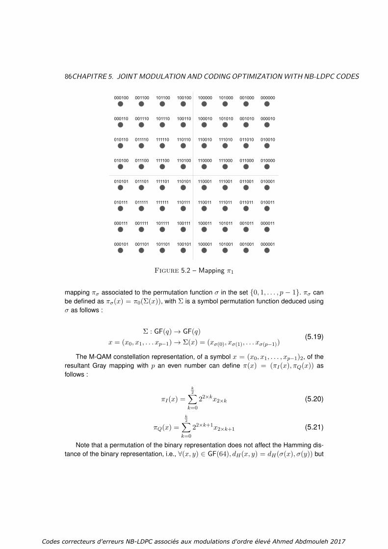
86CHAPITRE 5. JOINTMODULATION AND CODING OPTIMIZATIONWITH NB-LDPC CODES
Figure 5.2 – Mapping π1
mapping πσ associated to the permutation function σ in the set 0, 1, . . . , p − 1. πσ canbe defined as πσ(x) = π0(Σ(x)), with Σ is a symbol permutation function deduced usingσ as follows :
Σ : GF(q)→ GF(q)x = (x0, x1, . . . xp−1)→ Σ(x) = (xσ(0), xσ(1), . . . xσ(p−1))
(5.19)
The M-QAM constellation representation, of a symbol x = (x0, x1, . . . , xp−1)2, of theresultant Gray mapping with p an even number can define π(x) = (πI(x), πQ(x)) asfollows :
πI(x) =k2∑
k=022×kx2×k (5.20)
πQ(x) =k2∑
k=022×k+1x2×k+1 (5.21)
Note that a permutation of the binary representation does not affect the Hamming dis-tance of the binary representation, i.e., ∀(x, y) ∈ GF(64), dH(x, y) = dH(σ(x), σ(y)) but
Codes correcteurs d'erreurs NB-LDPC associés aux modulations d'ordre élevé Ahmed Abdmouleh 2017

5.6. INCIDENCE OF GRAYMAPPING CHOICE ON EUCLIDEAN DISTANCE AND DISTANCE SPECTRUM87
Figure 5.3 – Mapping π2
may affect the Euclidean distance after mapping, and this eventually modifies the DS of thecoded modulation.
Let us take the example of the Gray-mapped 64-QAM modulation. We can reconsiderthe mapping π0 already defined, and πσ a new Gray mapping where σ is a permutation inthe set 0, 1, . . . , 5 as πσ = π0(Σ(x)), with
Σ : GF(64)→GF(64)x = (x0, x1, . . . x5)→Σ(x) = (xσ(0), xσ(1), . . . xσ(5)).
(5.22)
Mappings in Fig. 5.2 and 5.3 can then be obtained from mapping π0 (Fig. 5.1) respec-tively by applying permutations σ1 and σ2 associated to permutations Σ1 and Σ2 on themapping π0, with Σ1(x) = (x3, x0, x2, x1, x5, x4) and Σ2(x) = (x4, x2, x1, x0, x5, x3).We can easily notice that the Euclidean distance between two distinct symbols x and yvaries depending of the used mapping. For instance, if x
′and y
′are two symbols that re-
present respectively the bit sequences (000000) and (000001), the Euclidean distance inmapping π0 (Fig. 5.1), Dπ0(x′ , y′) = dmin becomes Dπ1(x′ , y′) = 7× dmin with mappingπ1 (Fig. 5.2), and Dπ2(x′ , y′) = 7× dmin with mapping π2 (Fig. 5.3).
Therefore we have shown that changing the mapping can impact the Euclidean distancebetween two distinct symbols x and y, and thus an impact on the DS of a couple of code
Codes correcteurs d'erreurs NB-LDPC associés aux modulations d'ordre élevé Ahmed Abdmouleh 2017

88CHAPITRE 5. JOINTMODULATION AND CODING OPTIMIZATIONWITH NB-LDPC CODES
C and mapping π is inevitable. In the next section, we propose a joint optimization of themapping and the NB-LDPC code at the parity-check equation level. Then we generalize itto the whole PCM.
5.7 JOINT OPTIMIZATION OF MAPPING AND NB-LDPCMATRIX COEFFICIENTS
In this section, we propose to jointly optimize both modulation and PCM of NB-LDPCcode. We aim to find out the best couple mapping π and dc non-null entries that defines a(C, π) ∈ C in order to minimize error rate, where C is the set of all possible codes (C, π)defined by a combination of a mapping and non-null coefficients as entries. To fulfill thisobjective, we start by performing an exhaustive search among all the possible codes (C, π)among C that optimizes the DS, or in practice, that minimizes the first terms in Sπ,C(d), ford < du, with du the highest value that guarantees a minimum values of Sπ,C(d) for d < du.The optimal code (C, π)opt is thus selected as
(C, π)opt = min(C,π)∈C
maxdu∈R
Sπ,C(d);∀d < du (5.23)
In practice, the du value is incremented till we find out that Sπ,C(d) cannot be minimizedfor all values of d lower than du. As we have seen in Eq. 5.16, the first values of the DS arealways the most predominant values, therefore, there is no need to have a very importantdu value. For the dc non-null entries, we have qdc−1 possibilities of combinations of dc-tuples (the first non-null entry is set to α1). For the possible Gray mappings, we can deducefrom one Gray-mapped constellation, a number of p! possible mappings via an exhaustiveresearch. We can use the symmetries in the M-QAM mapping to reduce the number of Graymappings to be tested. The first symmetry can be modeled by a rotation around the origin.In figures Fig. 5.4, Fig. 5.5, Fig. 5.6 and 5.7 (4-QAM modulation), the represented constel-lations are associated to the mappings π′0, π′1, π′2 and π′3, respectively. The mappings π′1,π′2 and π′3 and the result of a rotation applied on the mapping π′0, using the angles 90,180 and 270, respectively. Such transformation do not change the Euclidean distancesbetween symbols, thus it is enough to test one of these mapping. The other mappings willhave exactly the same results in term of Euclidean distance and DS. Knowing this propertywe can reduce the number of the tested Gray-mapped constellation to n!
4 . We can easilygeneralize the explained property to all M-QAM modulations.
Another property of the M-QAM modulations can be used to lower the number of testedmappings. It consists on considering the diagonal symmetry. In figure Fig. 5.8 and 5.8 wecan notice that we used the mapping π′0 and the mapping π′5 the image of π′0 using adiagonal symmetry. Both constellations have same Euclidean distance and DS values. Thenumber of tested mapping can be divided again by 2 to reach a total number of testedGray-mapped constellation of n!
8 .
Codes correcteurs d'erreurs NB-LDPC associés aux modulations d'ordre élevé Ahmed Abdmouleh 2017

5.7. JOINT OPTIMIZATION OFMAPPING AND NB-LDPCMATRIX COEFFICIENTS89
α0
α1α2
α3I
Q
Figure 5.4 –Mapping π′0
α1
α2α3
α0I
Q
Figure 5.5 –Mapping π′1
α2
α3α0
α1I
Q
Figure 5.6 –Mapping π′2
α3
α0α1
α2I
Q
Figure 5.7 –Mapping π′3
α0
α1α2
α3I
Q
Figure 5.8 – Map-ping π′0
α0
α3α2
α1I
Q
Figure 5.9 – Map-ping π′5
If we consider again the example for the 64-QAM, the number of the tested Gray-mapped constellations will be 6!
8 = 90. For dc = 4, the exhaustive search for each mappingshould minimize the Sπ,C(2
√3) then Sπ,C(4) in the DS, since these two terms are consi-
dered as dominating terms for the high SNR regime performance of the coded modulation.We can use the proposed approximation developed in the previous section to perform theresearch. Such operation will be done only once, and then the results can be investigatedfor all PCM with dc = 4 and q = 64.
Table 5.1 presents three different coded modulations (C, π)i, i = 0, 1, 2, each one de-fined by a mapping πi, i = 0, 1, 2 as described in Fig. 5.1, Fig. 5.2, and Fig. 5.3 and aset of dc = 4 coefficients hk ∈ GF(q), k = 1 . . . dc. These codes have been chosen asfollows : (C, π)0 uses the DVB-T2 Gray mapping π0 [15] (See Fig. 5.1) and coefficients(α0, α9, α22, α37) as proposed in [25] ; (C, π)1 uses the same coefficients as (C, π)0 andmapping π1 (Gray mapping that maximizes Sπ,C(2
√3) in DS). Note that this corresponds
to the worst case, or equivalently the mapping that should show the worst performance forthe coded modulation when using the coefficients (α0, α9, α22, α37), and it is only discus-sed for comparison purposes. Finally, (C, π)2 is the new proposed combination of mappingand coefficients, i.e. mapping π2 in Fig. 5.3 with coefficients (α0, α8, α16, α42). It is obtai-ned after an exhaustive search which consists in calculating the two first terms of DS for alarge number of possible mapping/coefficients combinations. Note that (C, π)2 significantly
Codes correcteurs d'erreurs NB-LDPC associés aux modulations d'ordre élevé Ahmed Abdmouleh 2017
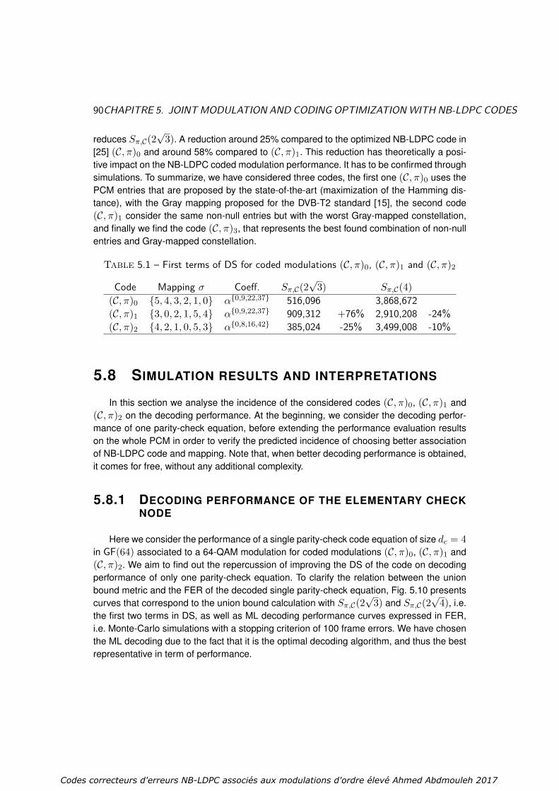
90CHAPITRE 5. JOINTMODULATION AND CODING OPTIMIZATIONWITH NB-LDPC CODES
reduces Sπ,C(2√
3). A reduction around 25% compared to the optimized NB-LDPC code in[25] (C, π)0 and around 58% compared to (C, π)1. This reduction has theoretically a posi-tive impact on the NB-LDPC coded modulation performance. It has to be confirmed throughsimulations. To summarize, we have considered three codes, the first one (C, π)0 uses thePCM entries that are proposed by the state-of-the-art (maximization of the Hamming dis-tance), with the Gray mapping proposed for the DVB-T2 standard [15], the second code(C, π)1 consider the same non-null entries but with the worst Gray-mapped constellation,and finally we find the code (C, π)3, that represents the best found combination of non-nullentries and Gray-mapped constellation.
Table 5.1 – First terms of DS for coded modulations (C, π)0, (C, π)1 and (C, π)2
Code Mapping σ Coeff. Sπ,C(2√
3) Sπ,C(4)(C, π)0 5, 4, 3, 2, 1, 0 α0,9,22,37 516,096 3,868,672(C, π)1 3, 0, 2, 1, 5, 4 α0,9,22,37 909,312 +76% 2,910,208 -24%(C, π)2 4, 2, 1, 0, 5, 3 α0,8,16,42 385,024 -25% 3,499,008 -10%
5.8 SIMULATION RESULTS AND INTERPRETATIONS
In this section we analyse the incidence of the considered codes (C, π)0, (C, π)1 and(C, π)2 on the decoding performance. At the beginning, we consider the decoding perfor-mance of one parity-check equation, before extending the performance evaluation resultson the whole PCM in order to verify the predicted incidence of choosing better associationof NB-LDPC code and mapping. Note that, when better decoding performance is obtained,it comes for free, without any additional complexity.
5.8.1 DECODING PERFORMANCE OF THE ELEMENTARY CHECKNODE
Here we consider the performance of a single parity-check code equation of size dc = 4in GF(64) associated to a 64-QAM modulation for coded modulations (C, π)0, (C, π)1 and(C, π)2. We aim to find out the repercussion of improving the DS of the code on decodingperformance of only one parity-check equation. To clarify the relation between the unionbound metric and the FER of the decoded single parity-check equation, Fig. 5.10 presentscurves that correspond to the union bound calculation with Sπ,C(2
√3) and Sπ,C(2
√4), i.e.
the first two terms in DS, as well as ML decoding performance curves expressed in FER,i.e. Monte-Carlo simulations with a stopping criterion of 100 frame errors. We have chosenthe ML decoding due to the fact that it is the optimal decoding algorithm, and thus the bestrepresentative in term of performance.
Codes correcteurs d'erreurs NB-LDPC associés aux modulations d'ordre élevé Ahmed Abdmouleh 2017
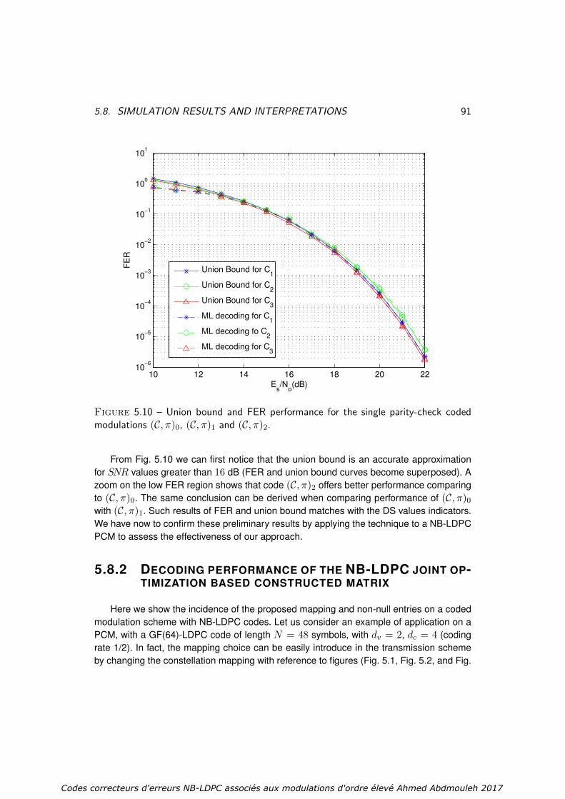
5.8. SIMULATION RESULTS AND INTERPRETATIONS 91
10 12 14 16 18 20 2210
−6
10−5
10−4
10−3
10−2
10−1
100
101
Es/N
o(dB)
FE
R
Union Bound for C1
Union Bound for C2
Union Bound for C3
ML decoding for C1
ML decoding fo C2
ML decoding for C3
Figure 5.10 – Union bound and FER performance for the single parity-check codedmodulations (C, π)0, (C, π)1 and (C, π)2.
From Fig. 5.10 we can first notice that the union bound is an accurate approximationfor SNR values greater than 16 dB (FER and union bound curves become superposed). Azoom on the low FER region shows that code (C, π)2 offers better performance comparingto (C, π)0. The same conclusion can be derived when comparing performance of (C, π)0with (C, π)1. Such results of FER and union bound matches with the DS values indicators.We have now to confirm these preliminary results by applying the technique to a NB-LDPCPCM to assess the effectiveness of our approach.
5.8.2 DECODING PERFORMANCE OF THE NB-LDPC JOINT OP-TIMIZATION BASED CONSTRUCTED MATRIX
Here we show the incidence of the proposed mapping and non-null entries on a codedmodulation scheme with NB-LDPC codes. Let us consider an example of application on aPCM, with a GF(64)-LDPC code of length N = 48 symbols, with dv = 2, dc = 4 (codingrate 1/2). In fact, the mapping choice can be easily introduce in the transmission schemeby changing the constellation mapping with reference to figures (Fig. 5.1, Fig. 5.2, and Fig.
Codes correcteurs d'erreurs NB-LDPC associés aux modulations d'ordre élevé Ahmed Abdmouleh 2017

92CHAPITRE 5. JOINTMODULATION AND CODING OPTIMIZATIONWITH NB-LDPC CODES
12.4 12.6 12.8 13 13.2 13.4 13.6 13.8 14 14.210
−9
10−8
10−7
10−6
10−5
10−4
10−3
Es/N
o(dB)
FE
R
(α0 α
9 α
22 α
37) with C
1
(α0 α
9 α
22 α
37) with C
2
(α0 α
8 α
16 α
42) with C
3
Figure 5.11 – EMS decoding performance of a N = 48 GF(64)-LDPC code with codedmodulations (C, π)0, (C, π)1 and (C, π)2, for a maximum of 100 erroneous frames
5.3), while the non-null entries must be carefully assigned to the non-null positions at eachrow in the matrix, i.e. for a single check node. To simplify task we will use protograph-based quasi-cyclic LDPC codes [115, 116]. Then, based on [25], we can perform a cyclecancellation and optimize the topological stopping set mitigation of the used the coefficientvalues presented in Table 5.1.
For the decoding algorithm, we consider the L-Bubble EMS decoding algorithm [42][119] with a number of significant values nm = 25 and 20 decoding iterations. The de-mapping step follows the principle described in [120] for simplified intrinsic Log-LikelihoodRatio generation. Simulation results show the effectiveness of the proposed optimizationapproach. Fig. 5.10 shows that (C, π)2 outperforms (C, π)0 and (C, π)1, especially in thehigh SNR regime region. To be specific, a gain of 0.2 dB (0.15 dB) at a FER = 2 × 10⁻⁸
with respect to (C, π)1 ((C, π)2) is achieved with the proposed solution. Note that this per-formance gain does not entail any additional complexity at the transmitter nor at the receivercompared to existing schemes, as the enhancement comes from the matrix constructionand the Gray mapping choice. Also note that even if the proposed approach is based onan exhaustive search to optimize the DS properties of the coded modulation, this step is
Codes correcteurs d'erreurs NB-LDPC associés aux modulations d'ordre élevé Ahmed Abdmouleh 2017

5.9. CONCLUSION 93
performed only once during the code design.
5.9 CONCLUSION
In this chapter we have considered the design of advanced high-spectral efficiencycommunications with good error-decoding performance. We focused on high-order NB-LDPC coded modulations where the order of the Galois Field and modulation order match.We have proposed to jointly optimize the parity-check equation of a NB-LDPC code andthe mapping of the GF(q) symbol in a q-ary constellation. We show an example of rateone half NB-LDPC over GF(64) associated with a 64-QAM performance improvement. Webased the NB-LDPC matrix optimization on the analysis of a single check node to find thebest GF(q) values for the dc coefficients for a given modulation mapping. To show the goodagreement between the theoretical analysis and practical implementation, we presentedand compared the union bound with the ML decoding curves of one parity-check equation.Finally, simulation results of NB-LDPC coded modulation, designed with the proposed me-thod, outperforms the state-of-the-art. The work can be extended to other types of q-aryconstellations, likes q-APSK (Asymmetrical Phase Shift Keying) for example, other q GaloisFields, and other code rates.
Codes correcteurs d'erreurs NB-LDPC associés aux modulations d'ordre élevé Ahmed Abdmouleh 2017

94
Codes correcteurs d'erreurs NB-LDPC associés aux modulations d'ordre élevé Ahmed Abdmouleh 2017

Chapitre 6
Conclusions and Perspectives
6.1 CONCLUSIONS
In the last years, the requirements of modern communication systems have significantlyincreased, especially in terms of data rate and transmission reliability. New transmissiondesigns that provide high spectral efficiency and good error correcting codes become es-sential to solve the problem of limited resources. In this context, this thesis explores the highorder modulation transmissions that use NB-LDPC codes. More specifically, it is devotedto study the association of highly efficient error-correcting codes, the NB-LDPC codes, withhigh order modulations. This type of association aims to design systems that are robust tonoise and efficient from the point of view of the occupied spectrum.
In our dissertation, we started our work with a detailed study of the state-of-the-art ofNB-LDPC codes. We began by recalling some basic mathematical notions that were usedto generalize the definition of binary LDPC codes on Galois Fields. Then we directed ourinterest to the various decoders proposed for NB-LDPC codes. We focused on the EMSalgorithm which is a generalization of the Min-Sum decoding algorithm. A performancecomparison between Binary and NB-LDPC codes was then presented in order to verifythe advantages of NB-LDPC codes. We then presented various elements of digital com-munication that are useful for our dissertation. We first presented some basic informationconcerning digital communications, in particular on digital carrier wave transmissions andtransmission channel models. Then, we advanced some characteristics of the various highorder modulations used in the study (M-QAM,M-PSK). Channel properties like Mutual Infor-mation, and channel capacity of Coded Modulation and Bit-Interleaved Coded Modulationschemes were introduced. Using a simplified algorithm allows to display some capacityand Mutual Information curves of the considered channels. Finally, we described the prin-ciple of the Signal Space Diversity technique, and introduced some of the state-of-the-artoptimizations.
After introducing some state-of-the-art advancements that are related to our disserta-tion, two main problematics are examined. The first one is related to the optimization of theSignal Space Diversity technique. The second topic considers the CM scheme optimization,
95
Codes correcteurs d'erreurs NB-LDPC associés aux modulations d'ordre élevé Ahmed Abdmouleh 2017

96 CHAPITRE 6. CONCLUSIONS AND PERSPECTIVES
where the NB-LDPC code and the modulation order matches.
The first contribution focuses on the SSD technique optimization in the context of highspectral efficiency communications, under the Rayleigh channel with and without erasure.The proposed optimization method was based on mutual information maximization, andcan be applied on any transmission using high-order modulation, i.e. M-QAM and A-PSKmodulations. The obtained results for optimal SSD rotation angles, when using CM andBICM schemes, and for different examples of M-QAM modulations, revealed two main in-teresting results. The first ascertainment shows that there is not an absolute optimal rotationangle for all SNRs. In other terms, the optimal rotation angle value depends on the SNR inthe considered transmission channel. For CM there exists a rotation angle close to optimalangle associated to all SNRs, which is not the case for BICM. The second main ascer-tainment showed that the association of NB-LDPC codes with M-QAM modulations (CMscheme) is more robust than the association of binary LDPC codes with M-QAM modula-tions (BICM scheme). In a theoretical point of view, the gain in terms of mutual informationobtained when using CM is always superior to that with BICM. In practice, simulation re-sults confirm that SSD technique introduces more significant gains in the CM scheme thanin the BICM one. Such contribution is important for the next generation broadcasting sys-tems, and can benefit to NB-LDPC codes to be a good alternative to the existing binarydecoding codes in the current transmission systems.
The second contribution in this thesis concerns a new method to design an advancedhigh-spectral efficiency communication CM scheme. The main idea behind the new pro-posed method is to jointly optimize the NB-LDPC code and the M-QAM modulation, theadvantage of using the same order for both (q=M). Such method is different to what is donesubsequently, where the NB-LDPC codes and modulation are optimized in a disjoint way.The key motivation behind the proposed optimization method was the difference of valuesbetween Euclidean distance and Hamming distance in a case of non-binary modulationtransmission (M >> 2). That implies that changing the modulation can impact the Eucli-dean distance between two codewords. The optimization method is concentrated on onesingle parity-check equation, and proposes the mapping and the dc coefficients in GF(q)that maximize the Euclidean distance between codewords, and minimize the distance spec-trum of the Euclidean distances, especially the lowest ones. We studied an example ofapplication : a one half rate NB-LDPC code over GF(64) associated with a 64-QAM mo-dulation. Through an exhaustive research we proposed to compare three different codesassociated to distinct couples of mapping π and dc non-null entries. The proposed codesaim to get out the influence of the joint choice of mapping and non-null entries. The firstcode uses the DVB-T2 Gray mapping and coefficients as proposed in the state-of-the-art,while the second one uses the same coefficients but with the worst mapping case. The thirdone is the result of the exhaustive research of the optimal combination of mapping and co-efficients. To clear up the interest of the proposed idea, and to show the good agreementwith the theoretical analysis and simulation are performed with the three considered codes.The results proved that a gain of 0.2 dB can be reached when using the optimal mapping
Codes correcteurs d'erreurs NB-LDPC associés aux modulations d'ordre élevé Ahmed Abdmouleh 2017

6.2. PERSPECTIVES 97
and NB-LDPC codes. It is important to mention that the gain is obtained without any additio-nal complexity compared to existing schemes. We only have to modify the encoding matrixconstruction and modulation labeling, after performing only once, an exhaustive search ofthe best labeling and NB-LDPC code for the transmission CM scheme.
Additional work has been performed during this PhD thesis that has not been addressedin this manuscript. I participated in a work that aims to construct protograph based QC-NB-LDPC codes matrix. This work was done to introduce the proposed non-null coefficientin our joint parity-check matrix (PCM) and modulation optimization. In fact, the prototypematrix uses integer values that correspond to the right-rotations of the identity matrices thatform the PCM structure. The determination of those integer values is a difficult problem.Based on an exhaustive examination of a simple prototype matrix, we propose a methodthat reduces the search space by defining topological classes of identical matrices throughline and/or column permutations, and by satisfying the programmed constraints to list theexhaustive set of solutions for a given girth and a given expansion factor.
6.2 PERSPECTIVES
Concerning the SSD technique proposed optimization, the mutual information basedoptimization can be extended to other types of q-ary constellations like the q-APSK modu-lations, other Galois Fields orders, and other code rates. SSD can also be applied on highdimension transmission i.e. 4-dimension transmission. By considering the mutual informa-tion metric, we can find the most performing rotation angles for different SNR values. Thenwe can provide a detailed study of the SSD impact on a high dimension transmission in thecontext of the Rayleigh channel with and without erasure.
We can find out different perspectives of development of the joint optimization methodof NB-LDPC codes and modulation. First, the proposed joint optimization can be treatedfor transmission with different rates and codeword lengths. Second, a generalization forother types of constellation is required. In spite of the fact that the M-QAM modulation hasgood characteristics in terms of regularity of distances between constellation points, otherconstellations i.e. PSK constellation can be a subject of study. Third, other non-binary codescan be considered in the proposed optimization method. In fact, NB-LDPC codes are thecorrecting codes considered in this thesis, but the proposed optimization method can begeneralized to any non-binary code, e.g. non-binary turbo codes. Relationship betweennon-binary codes and modulation can be studied in terms of Euclidean distance of thecodewords in order to enhance the performance results.
Finally, another perspective of development in the same context concerns the construc-tion of PCM with dv equal to 2. In fact, the couple of coefficients associated to each variablecan impact the decoding performance, especially in the waterfall zone. To verify such as-sumption, some promising preliminary decoding curves are already obtained for very shortPCM, which may lead to interesting results. This is done in the context of joint optimiza-tion of non-binary codes and modulation, and can offer an interesting development field in
Codes correcteurs d'erreurs NB-LDPC associés aux modulations d'ordre élevé Ahmed Abdmouleh 2017

98 CHAPITRE 6. CONCLUSIONS AND PERSPECTIVES
future studies.
Codes correcteurs d'erreurs NB-LDPC associés aux modulations d'ordre élevé Ahmed Abdmouleh 2017

Bibliographie
[1] D. J. C. MacKay and R. M. Neal, “Near Shannon limit performance of low densityparity check codes,” IEEE electronics letters, Aug 1996.
[2] A. Abdmouleh, E. Boutillon, L. Conde-Canencia, C. A. Nour, and C. Douillard, “Onsignal space diversity for non binary coded modulation schemes,” IEEE InternationalConference on Telecommunications (ICT), May 2016.
[3] ——, “A new approach to optimise Non-Binary LDPC codes for coded modulations,”IEEE International Symposium on turbo Codes and Iterative Information Proces-sing (ISTC), pp. 295–299, Sep 2016.
[4] E. Boutillon and A. Abdmouleh, “Methods and devices for generating optimized co-ded modulations,” N Demande : EP16306110.4, Déposant : UNIVERSITE DE BRE-TAGNE SUD, Sep 2016.
[5] R. Lidl and H. Niederreiter, Finite fields. Cambridge : Cambridge University Press,2008.
[6] J.-P. Deschamps and G. D. Sutter, Hardware implementation of finite field arithme-tic. New York : McGraw-Hill, 2009.
[7] J. M. Howie, Fields and Galois Theory. London : Springer Undergraduate Mathe-matics Series, 2007.
[8] A. Chamas, “Les codes LDPC non-binaire du nouvelle generation.” Ph.D. disserta-tion, Université de Cergy-Pontoise, Dec. 2010, direction : D. Declercq, V. Heinrich.
[9] C. Poulliat, M. Fossorier, and D. Declercq, “Design of non binary LDPC codes usingtheir binary image : algebraic properties,” IEEE International Symposium on Infor-mation Theory, pp. 93–97, July 2006.
[10] S. Scholl, “GF Matrix Elements.” [Online]. Available : http ://www.uni-kl.de/en/channel-codes/channel-codes-database/non-binary-ldpc/
[11] C. Berrou, A. Glavieux, and P. Thitimajshima, “Near Shannon limit error-correctingcoding and decoding : Turbo-codes,” In Communications, 1993. ICC ’93 Geneva.Technical Program, Conference Record, IEEE International Conference on,, vol. 2,pp. 1064–1070, 1993.
99
Codes correcteurs d'erreurs NB-LDPC associés aux modulations d'ordre élevé Ahmed Abdmouleh 2017

100 BIBLIOGRAPHIE
[12] C. E. Shannon, “A mathematical theory of communication,” Bell System TechnicalJournal, vol. 27, pp. 379–423 and 623–656, 1948.
[13] R. G. Gallager, Low-density parity-check codes. MIT, Cambridge, Mass : PhDthesis, 1963.
[14] D. J. C. MacKay, “Good error-correcting codes based on very sparse matrices,” IEEETransactions on Information Theory, vol. 45, no. 2, pp. 399–431, Aug 1999.
[15] “Digital Video Broadcasting (DVB) ; frame structure, channel coding and modulationfor a second generation digital terrestrial television broadcasting system (DVB-T2),”in ETSI EN 302 755, 2010-10.
[16] “Digital Video Broadcasting (DVB) ; Modulation Interface (C2-MI) for a second gene-ration digital transmission system for cable systems (DVB-C2),” in ETSI TS 103 287,2000.
[17] “Digital Video Broadcasting (DVB) ; Second generation framing structure, channel co-ding and modulation systems for Broadcasting, Interactive Services, News Gatheringand other broadband satellite applications (DVB-S2),” in ETSI EN 302 307, 2009.
[18] IEEE STANDARDS ASSOCIATION, IEEE Standard for Air Interface for BroadbandWireless Access Systems. 3 Park Avenue, New York, NY 10016-5997 USA : IEEEComputer Society, 2012.
[19] T. J. Richardson, M. A. Shokrollahi, and R. L. Urbanke, “Design of capacity approa-ching irregular low density parity check codes,” IEEE Transactions on InformationTheory, vol. 47, no. 2, pp. 619–637, 2001.
[20] J. Moreira, Essentials of error-control coding. West Sussex, England : John WileySons, 2006.
[21] R. Tanner, “A recursive approach to low complexity codes,” IEEE Transactions onInformation Theory, vol. 27, no. 5, pp. 533–547, 1981.
[22] M. Davey and D. MacKay, “Low-density parity check codes over GF(q),” IEEE Com-munications Letters, vol. 2, no. 6, p. 165–167, 1998.
[23] R. G. Gallager, “Low density parity check codes,” IEEE transaction on Informationtheory, vol. IT-8, p. 21–28, Jan 1962.
[24] N. Wiberg, Codes and decoding on general graphs. Likoping University sweden :PhD thesis, 1996.
[25] C. Poulliat, M. Fossorier, and D. Declercq, “Design of regular (2, dc)-LDPC codesover GF(q) using their binary images,” IEEE Transactions on Communications,vol. 56, pp. 1626–1635, Oct 2008.
[26] D. Declercq and M. Fossorier, “Decoding algorithms for non-binary LDPC codes overGF(q),” IEEE Transactions on Communications, vol. 55, no. 4, pp. 633–643, 2007.
Codes correcteurs d'erreurs NB-LDPC associés aux modulations d'ordre élevé Ahmed Abdmouleh 2017

BIBLIOGRAPHIE 101
[27] A. Voicila, D. Declercq, F. Verdier, M. Fossorier, and P. Urard, “Low complexity deco-ding algorithm for non-binary LDPC codes in high order fields,” IEEE Transactionson Communications, vol. 58, no. 5, pp. 1–11, May 2010.
[28] H. Wymeersch, H. Steendam, and M. Moeneclaey, “Log-domain decoding of LDPCcodes over GF(q),” Communications, 2004 IEEE International Conference on, vol. 2,pp. 772–776, Jun 2004.
[29] A. Voicila, “Décodage simplifie des codes LDPC non-binaires.” Ph.D. dissertation,Universite de Cergy-Pontoise, sept. 2007, direction : D. Declercq, F. Verdier.
[30] D. Declercq, M. Colas, and G. Gelle, “Regular GF(2q)-LDPC coded modulations forhigher order QAM-AWGN channel,” Proc. ISITA. Parma, Italy, Oct 2004.
[31] L. Ma, L. Wang, and J. Zhang, “Performance advantage of non-binary LDPC codesat high code rate under AWGN channel,” Communication Technology, 2006. ICCT’06. International Conference on, Nov 2006.
[32] X. Jiand, Y. Yan, X. Xia, and M. H. Lee, “Application of non-binary LDPC codes basedon euclidean geometries to MIMO systems,” Proceedings of Intern. conference onwireless comm. and Signal processing, pp. 1–5, Nov 2009.
[33] H. Song and J. Cruz, “Reduced-complexity decoding of q-ary LDPC codes for ma-gnetic recording,” IEEE Transactions on Magnetics, vol. 39, no. 2, p. 1081–1087,2003.
[34] X. Hu and E. Eleftheriou, “Binary representation of cycle tannergraph GF(2q) codes,”IEEE International Conference on Communications, Jun 2004.
[35] S. Pfletschinger, A. Mourad, E. Lopez, D. Declercq, and G. Bacci, “Performance eva-luation of non-binary LDPC codes on wireless channels,” In Proceedings of ICTMobile summit, Jun 2009.
[36] M. Arabaci and I. B. Djordjevic, “Binary and nonbinary LDPC-coded modulations forgeneralized fading channels,” Telecommunication in Modern Satellite Cable andBroadcasting Services (TELSIKS), 2011 10th International Conference on, Oct2011.
[37] G. Li, I. J. Fair, and W. Krzymien, “Density evolution for nonbinary LDPC codes underGaussian approximation,” IEEE Transactions on Information Theory, vol. 55, no. 3,pp. 997–1015, Mar 2009.
[38] M. Yang and W. Ryan, “Performance of Quasi-Cyclic LDPC codes in noise bursts onthe EPR4 channel,” Proceedings of IEEE GLOBECOM, pp. 2961–2965, Nov 2001.
[39] A. Morinoni, P. Savazzi, and S. Valle, “Efficient design of non-binaryLDPC codes for magnetic recording channels, robust to error bursts,”5thInternationalSymposiumonTurboCodesandRelatedTopics, pp.288 −−293, Sept2008.
Codes correcteurs d'erreurs NB-LDPC associés aux modulations d'ordre élevé Ahmed Abdmouleh 2017

102 BIBLIOGRAPHIE
[40] T. Chehade, L. Collin, P. Rostaing, O. Bazzi, and E. Radoi, “Adaptive minimum-distance based precoder for NB-LDPC coded MIMO transmission,” IEEE GlobalCommunications Conference (GLOBECOM), Dec 2015.
[41] G. Caire, G. Taricco, and E. Biglieri, “Bit-interleaved coded modulation,” IEEE Tran-sactions on Information Theory, vol. 44, no. 3, pp. 927–946, May 1998.
[42] E. Boutillon, L. Conde-Canencia, and A. Al-Ghouwayel, “Design of a GF(64)-LDPCdecoder based on the EMS algorithm,” IEEE Transactions on Circuits and Systems-I : Regular Papers, vol. 60, no. 10, Oct. 2013.
[43] B. Sklar, “Rayleigh fading channels in mobile digital communication systems .i. cha-racterization,” IEEE Communications Magazine, vol. 35, no. 4, pp. 90–100, July1997.
[44] J. D. Parsons, The mobile radio propagation channel. New York, USA : John Wileysons, 1992.
[45] S. Benedetto and E. Biglieri, Principles of digital transmission with wireless appli-cations. norwell, MA, USA : Kluwer Academic Publishers, 1999.
[46] European Standard (Telecommunications series), “Digital Video Broadcasting(DVB) ; Framing structure, channel coding and modulation for digital terrestrial te-levision,” in ETSI EN 300 744, 2009-01.
[47] IEEE STANDARDS ASSOCIATION, Wireless LAN Medium Access Control (MAC)and Physical Layer (PHY) Specifications. 3 Park Avenue, New York, NY 10016-5997 USA : IEEE Computer Society, 2012.
[48] L. Cimini, “Analysis and simulation of a digital mobile channel using orthogonal fre-quency division multiplexing,” IEEE Transactions on Communications, vol. 33, no. 7,pp. 665–675, Jul 1985.
[49] M. Mendicute, I. Sobrón, L. Martínez, and P. Ochandiano, DVB-T2 : New SignalProcessing Algorithms for a Challenging Digital Video Broadcasting Standard.University of Mondragon, spain : Floriano De Rango, 2010.
[50] C. Abdel Nour and C. Douillard, “Improving BICM performance of QAM constellationsfor broadcasting applications,” IEEE International Symposium on Turbo Codes andRelated Topics, pp. 55–60, Sept 2008.
[51] J. K. Cavers, “An analysis of pilot symbol assisted modulation for Rayleigh fadingchannels,” IEEE Transactions on Vehicular Technology, p. 686–693, Nov 1991.
[52] E. Boch, “High-capacity ethernet backhaul radio systems for advanced mobile datanetworks,” IEEE Microwave Magazine, vol. 10, no. 5, pp. 108–114, Aug 2009.
[53] S. Scholl, “Global mobile data traffic, 2015 to 2020.” [Online]. Avai-lable : http ://www.cisco.com/c/en/us/solutions/collateral/service-provider/visual-networking-index-vni/mobile-white-paper-c11-520862.html
Codes correcteurs d'erreurs NB-LDPC associés aux modulations d'ordre élevé Ahmed Abdmouleh 2017
BIBLIOGRAPHIE 103
[54] “Digital Video Broadcasting (DVB), Next Generation broadcasting system to hand-held, physical layer specification (DVB-NGH),” in DVB Document A160, 2012.
[55] A. T. Le and K. Araki, “A group of modulation schemes for adaptive modulation,”IEEE International Conference on Communication Systems (ICCS), pp. 864–869,Nov 2008.
[56] D. A. Bryan, “QAM for terrestrial and cable transmission,” IEEE Transactions onConsumer Electronics, vol. 41, pp. 383–391, Aug 1995.
[57] “Universal Mobile Telecommunications System (UMTS) ; High Speed Downlink Pa-cket Access (HSDPA) ; Overall description ; Stage 2 (3GPP TS 25.308 version 10.6.0Release 10),” in ETSI TS 125 308, 2012.
[58] “LTE ; Evolved Universal Terrestrial Radio Access (E-UTRA) ; User Equipment (UE)radio transmission and reception (3GPP TS 36.101 version 12.5.0 Release 12) ,” inETSI TS 136 101, 2014.
[59] “Data-over-cable Service Interface Specifications Radio Frequency Interface Specifi-cation,” in ETSI ES 201 488, 2000.
[60] “Integrated Broadband Cable Telecommunication Networks (CABLE) ; cable equip-ment operations within its frequency band,” in ETSI TS 102 866, 2014.
[61] T. Cover and J. Thomas, Elements of Information Theory. New York Wiley, 1991.
[62] E. Boutillon, Y. Eustache, P. Bomel, A. Haroune, and L. Conde-Canencia, “Perfor-mance measurement of davinci code by emulation,” INFSCO-ICT-216203 DA VINCID6.2.3 v1.0, p. 1–47, July 2011.
[63] R. M. Gray, Entropy and Information Theory. Springer-Verlag New York : Infor-mation Systems Laboratory Electrical Engineering Department Stanford University,2013.
[64] E. Zehavi, “8-PSK trellis codes for a Rayleigh channel,” IEEE Transactions on Com-munications, vol. 40, no. 3, p. 873–884, May 1992.
[65] G. Caire, G. Taricco, and E. Biglieri, “Bit-interleaved coded modulation,” IEEE Tran-sactions on Information Theory, vol. 44, no. 3, pp. 927–946, May 1998.
[66] A. Goldsmith, Wireless Communications. New York, NY : Cambridge UniversityPress, 2005.
[67] G. Ungerboeck, “Channel coding with multilevel/phase signals,” IEEE Transactionson Information Theory, vol. 28, no. 1, pp. 55–67, Jan 1982.
[68] IEEE 802, Wireless LAN medium access control (MAC) and physical layer (PHY)specifications : High-speed physical layer in the 5GHz band. Tech. Rep : 802.11a-1999(R2003), 2009.
[69] I. Koffman and V. Roman, “Broadband wireless access solutions based on OFDMaccess in IEEE 802.16,” IEEE Communications Magazine, vol. 40, no. 4, pp. 96–103, Apr 2002.
Codes correcteurs d'erreurs NB-LDPC associés aux modulations d'ordre élevé Ahmed Abdmouleh 2017

104 BIBLIOGRAPHIE
[70] J. Jalden, P. Fertl, and G. Matz, “On the generalized Mutual Information of BICMsystems with approximate demodulation,” Information Theory (ITW 2010, Cairo),2010 IEEE Information Theory Workshop on, Jan 2010.
[71] D. MacKay, Information Theory, Inference, and Learning Algorithms. CambridgeUniversity, UK : Cambridge University Press, 2003.
[72] J. Boutros and E. Viterbo, “Signal space diversity : A power and bandwidth efficientdiversity technique for the Rayleigh fading channel,” IEEE TRANSACTIONS ONINFORMATION THEORY, vol. 44, no. 4, pp. 1453–1467, July 1998.
[73] N. H. Tran, H. H. Nguyen, and T. Le-Ngoc, “Application of signal space diversity overmultiplicative fading channels,” IEEE Signal Processing Letters, vol. 16, no. 3, pp.204–207, mar 2009.
[74] J. Yang, K. Wan, B. Geller, C. Abdel Nour, O. Rioul, and C. Douillard, “A low-complexity 2d signal space diversity solution for future broadcasting systems,” IEEEInternational Conference on Communications (ICC), pp. 2762–2767, Jun 2015.
[75] “DVB fact sheet. DVB-T2, 2nd generation terrestrial,” 2010-08.
[76] K. Boulle and J. C. Belfiore, “Modulation schemes designed for the Rayleigh fadingchannel,” presented at CISS 92, Princeton, NJ, mar 1992.
[77] G. Taricco and E. Viterbo, “Performance of component interleaved signal sets forfading channels,” Electronics Letters, vol. 32, no. 13, p. 1170–1172, April 1996.
[78] S. B. Slimane, “An improved PSK scheme for fading channels,” IEEE Transactionson Vehicular Technology, vol. 47, no. 2, p. 703–710, May 1998.
[79] R. Schober, L. H.-J. Lampe, W. H. Gerstacker, and S. Pasupathy, “Modulation diver-sity for frequency-selective channels,” IEEE Transactions on Information Theory,no. 9, p. 2268–2276, Sept 2003.
[80] J. Boutros, E. Viterbo, C. Rastello, and J.-C. Belfiore, “Good lattice constellations forboth Rayleigh fading and Gaussian channels,” IEEE Transactions on InformationTheory, vol. 42, no. 2, pp. 502–518, mar 1996.
[81] C. Abdel Nour and C. Douillard, “Rotated QAM Constellations to improve BICM per-formance for DVB-T2,” IEEE International Symposium on Spread Spectrum Tech-niques and Applications, pp. 354–359, Aug 2008.
[82] Z. Wu, Y. Shi, X. Chen, and Y. Zhu, “An efficient component-interleaved non-binarylow density parity check code scheme on Rayleigh fading channels,” Communica-tions and Networking (BlackSeaCom), 2014 IEEE International Black Sea Confe-rence on, May 2014.
[83] G. K. Karagiannidis, N. C. Sagias, and P. T. Mathiopoulos, “N*Nakagami : A novelstochastic model for cascaded fading channels,” IEEE Transactions on Communi-cations, vol. 55, no. 8, pp. 1453–1468, Aug 2007.
Codes correcteurs d'erreurs NB-LDPC associés aux modulations d'ordre élevé Ahmed Abdmouleh 2017

BIBLIOGRAPHIE 105
[84] Z. Wu and X. Gao, “An efficient MIMO scheme with signal space diversity for fu-ture mobile communications,” EURASIP Journal on Wireless Communications andNetworking, mar 2015.
[85] B. Sklar, “Rayleigh fading channels in mobile digital communication systems .i. cha-racterization,” IEEE Communications Magazine, vol. 35, no. 7, pp. 90 – 100, Jul1997.
[86] ——, “Rayleigh fading channels in mobile digital communication systems part ii :Mitigation,” IEEE Communications Magazine, vol. 35, no. 9, pp. 148–155, Sept 1997.
[87] M. Li, C. Abdel Nour, C. Jégo, and C. Douillard, “Design of rotated QAM map-per/demapper for the DVB-T2 standard,” SiPS, Finland, pp. 18–23, Oct 2009.
[88] W. Zhou and L. Zou, “Optimized rotations and labeling for non-binary LDPC codedmodulation with signal space diversity,” IEEE International Symposium on Broad-band Multimedia Systems and Broadcasting, May 2009.
[89] S. Jeony, J. Lee, I. Kyung, and M.-S. Kim, “Component-interleaved Alamouti codingwith rotated constellations for signal space diversity,” IEEE International Symposiumon Broadband Multimedia Systems and Broadcasting (BMSB), Mar 2010.
[90] S. M. Alamouti, “A simple transmit diversity technique for wireless communications,”IEEE Journal on Selected Areas in Communications, vol. 6, no. 8, pp. 1451–1458,Oct 1998.
[91] L. Polak and T. Kratochvil, “Performance of the rotated constellation in DVB-T2,” TheSeventh International Conference on Digital Telecommunications ICDT, pp. 84–87,2012.
[92] S. Lin and D. J. Costello, Error Control Coding, Englewood Cliffs, NJ : Prentice-Hall,2004.
[93] R. Krishnan, A. Graell i Amat, T. Eriksson, and G. Colavolpe, “Constellation optimiza-tion in the presence of strong phase noise,” IEEE Transactions on Communications,vol. 61, no. 12, pp. 5056–5066, Dec 2013.
[94] M. F. Barsoum, C. Jones, and M. Fitz, “Constellation design via capacity maximiza-tion,” IEEE International Symposium on Information Theory, Jun 2007.
[95] U. Wachsmann, R. Fischer, and J. B. Huber, “Multilevel codes : theoretical conceptsand practical design rules,” IEEE Transactions on Information Theory, vol. 45, no. 5,p. 1361–1391, Jul 1999.
[96] J. Zoellner and N. Loghin, “Optimization of high-order non-uniform QAM constel-lations,” IEEE International Symposium on Broadband Multimedia Systems andBroadcasting, Jun 2013.
[97] B. Zhang and K. Kiasaleh, “Partially-coherent receivers architectures for QAM com-munications in the presence of non-constant phase estimation error,” IEEE Transac-tions on Wireless Communications, vol. 8, no. 2, pp. 568–573, Feb 2009.
Codes correcteurs d'erreurs NB-LDPC associés aux modulations d'ordre élevé Ahmed Abdmouleh 2017

106 BIBLIOGRAPHIE
[98] R. Rios-Müller, J. Renaudier, L. Schmalen, and G. Charlet, “Joint coding rate andmodulation format optimization for 8-QAM constellations using BICM Mutual Infor-mation,” Optical Fiber Communications Conference and Exhibition (OFC), March2015.
[99] F. Kayhan and G. Montorsi, “Constellation design for channels affected by phasenoise,” IEEE International Conference on Communications (ICC), pp. 3154–3158,Jun 2013.
[100] ——, “Joint signal-labeling optimization for pragmatic capacity under peak-powerconstraint,” IEEE Global Telecommunications Conference, Dec 2010.
[101] C. Marchand and E. Boutillon. (2015, Jul.) Lab-STICC website on Non-Binary LDPC.[Online]. Available : http ://www-labsticc.univ-ubs.fr/nb_ldpc/
[102] G. Ungerboeck, “Trellis-coded modulation with redundant signal sets part i : Intro-duction.” IEEE Communications Magazine, vol. 25, no. 2, pp. 5–11, 1987.
[103] G. Richter, A. Hof, and M. Bossert, “On the mapping of low-density parity-checkcodes for bit-interleaved coded modulation,” IEEE International Symposium on In-formation Theory, p. 2146–2150, Jun 2007.
[104] S.-Y. Chung, G. Forney, T. Richardson, and R. Urbanke, “On the design of low-densityparity-check codes within 0.0045 db of the Shannon limit,” IEEE CommunicationsLetters, vol. 5, no. 2, p. 58–60, July 2001.
[105] A. Bennatan and D. Burshtein, “On the application of LDPC codes to arbitrarydiscrete-memoryless channels,” IEEE Transactions on Information Theory, vol. 50,no. 3, pp. 417–438, Mar 2004.
[106] ——, “Design and analysis of non-binary LDPC codes for arbitrary discrete memo-ryless channels,” IEEE Transactions on Information Theory, vol. 52, pp. 549–583,Feb 2009.
[107] G. Li, I. J. Fair, and W. Krzymien, “Analysis of non-binary LDPC codes using Gaus-sian approximation,” IEEE International Symp. on Inf. Theory, Yokohama, Japan,July 2003.
[108] V. Rathi and R. Urbanke, “Density evolution, thresholds and the stability condition fornon-binary LDPC codes,” IEEE Proceedings, vol. 152, no. 6, pp. 1069–1074, Dec2005.
[109] D. MacKay. (2003, Aug) Optimizing sparse graph codes over GF(q).
[110] L. Zeng, L. Lan, Y. Y. Tai, S. Song, S. Lin, and K. Abdel-Ghaffar, “Constructions ofnon-binary Quasi-Cyclic LDPC codes : A finite field approach,” Transactions Papers,apr 2008.
[111] D. Kimura, F. Guilloud, and R. Pyndiah, “Construction of parity-check matrices fornon-binary LDPC codes,” 4th International Symposium on Turbo Codes and Rela-ted Topics, apr 2006.
Codes correcteurs d'erreurs NB-LDPC associés aux modulations d'ordre élevé Ahmed Abdmouleh 2017

BIBLIOGRAPHIE 107
[112] J. Thorpe, “Low-density parity-check (LDPC) codes constructed from protographs,”Interplanetary Network Progress Report, vol. 154, pp. 1–7, Aug 2003.
[113] R. Smarandache, D. G. Mitchell, and D. J. Costello, “Partially Quasi-CyclicProtograph-based LDPC codes,” Communications (ICC), 2011 IEEE InternationalConference on, Jun 2011.
[114] X. Zhang and Y. Tai, “Low-complexity transformed encoder architectures for Quasi-Cyclic non-binary LDPC codes over subfields,” IEEE Transactions on Very LargeScale Integration (VLSI) Systems, pp. 1–10, Dec 2016.
[115] B. Amiri, J. A. F. Castro, and L. Dolecek, “Design of non-binary Quasi-Cyclic LDPCcodes by absorbing set removal,” Information Theory Workshop (ITW), 2014 IEEE,Dec 2014.
[116] J. Li, K. Liu, S. Lin, and K. Abdel-Ghaffar, “A matrix-theoretic approach to theconstruction of non-binary Quasi-Cyclic LDPC codes,” IEEE Transactions on Com-munications, vol. 63, no. 4, pp. 1057–1068, Feb 2015.
[117] R. Smarandache and P. O. Vontobe, “Quasi-Cyclic ldpc codes : Influence of proto-and Tanner-graph structure on minimum Hamming distance Upper Bounds,” IEEETransactions on Information Theory, vol. 58, no. 2, pp. 585–607, Feb 2012.
[118] X. Hu, E. Eleftheriou, and D. Arnold, “Regular and irregular Progressive Edge-GrowthTanner graphs,” IEEE Transactions on Information Theory, vol. 51, no. 1, pp. 386–398, Jan 2005.
[119] E. Boutillon and L. Conde-Canencia, “Simplified check node processing in non-binaryLDPC decoders,” in 6th International Symposium on Turbo Codes Iterative Infor-mation Processing, Sept 2010, pp. 201–205.
[120] L. Conde-Canencia and E. Boutillon, “Application of bubble-check algorithm to non-binary LLR computation in QAM coded schemes,” Electronics Letters, vol. 50, no. 25,pp. 1937–1938, 2014.
Codes correcteurs d'erreurs NB-LDPC associés aux modulations d'ordre élevé Ahmed Abdmouleh 2017