Stainless Steel Pipes / Stainless Steel Compression Pipe Fittings
Page 1OPERATING MANUAL - AHM-1B HOPPER MOUNT DRYERRevision 3/31/02
DRI-AIR INDUSTRIES, INC.
AHM-1B HOPPERMOUNT DRYER
OPERATING MANUAL

Page 2 OPERATING MANUAL - AHM-1B HOPPER MOUNT DRYERRevision 3/31/02
DRI-AIR INDUSTRIES, INC.
DRI-AIR INDUSTRIES, INC.
16 THOMPSON ROADP.O. BOX 1020EAST WINDSOR, CT 06088-1020
Tel. (860) 627-5110FAX (860) 623-4477Internet http://www.dri-air.come-mail: [email protected]
Page 3OPERATING MANUAL - AHM-1B HOPPER MOUNT DRYERRevision 3/31/02
DRI-AIR INDUSTRIES, INC.
CONTENTS
DRYER DESCRIPTION Pg 4
AIR FLOW SCHEMATIC Pg 7
DRYER CYCLE DIAGRAM Pg 8
INSTALLATION PROCEDURE Pg 9
START-UP PROCEDURE Pg 11
ROUTINE MAINTENANCE Pg 12
BASIC TROUBLE-SHOOTING Pg 13
DETAILED TROUBLE-SHOOTING Pg 14
ZONE VALVE TROUBLE-SHOOTING Pg 16
CONTROLS TROUBLE-SHOOTING Pg 16
PARTS LIST Pg 17
ELECTRICAL SCHEMATIC Appendix
Page 4 OPERATING MANUAL - AHM-1B HOPPER MOUNT DRYERRevision 3/31/02
DRI-AIR INDUSTRIES, INC.
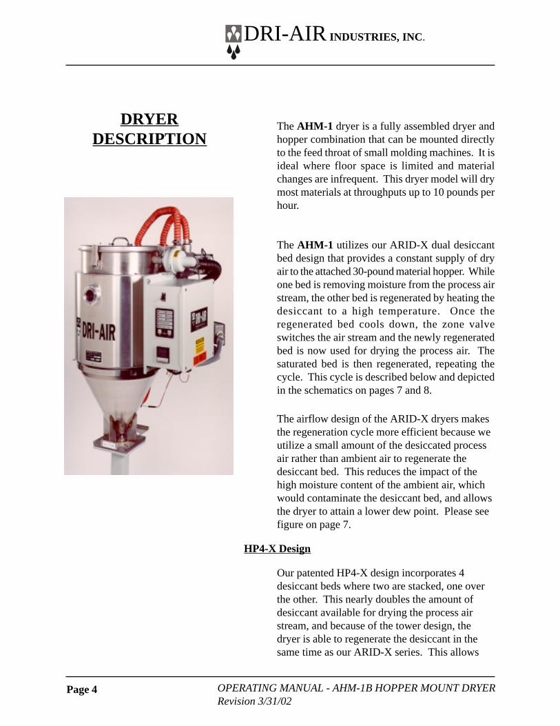
The AHM-1 dryer is a fully assembled dryer andhopper combination that can be mounted directlyto the feed throat of small molding machines. It isideal where floor space is limited and materialchanges are infrequent. This dryer model will drymost materials at throughputs up to 10 pounds perhour.
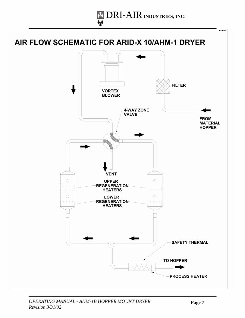
The AHM-1 utilizes our ARID-X dual desiccantbed design that provides a constant supply of dryair to the attached 30-pound material hopper. Whileone bed is removing moisture from the process airstream, the other bed is regenerated by heating thedesiccant to a high temperature. Once theregenerated bed cools down, the zone valveswitches the air stream and the newly regeneratedbed is now used for drying the process air. Thesaturated bed is then regenerated, repeating thecycle. This cycle is described below and depictedin the schematics on pages 7 and 8.
The airflow design of the ARID-X dryers makesthe regeneration cycle more efficient because weutilize a small amount of the desiccated processair rather than ambient air to regenerate thedesiccant bed. This reduces the impact of thehigh moisture content of the ambient air, whichwould contaminate the desiccant bed, and allowsthe dryer to attain a lower dew point. Please seefigure on page 7.
HP4-X Design
Our patented HP4-X design incorporates 4desiccant beds where two are stacked, one overthe other. This nearly doubles the amount ofdesiccant available for drying the process airstream, and because of the tower design, thedryer is able to regenerate the desiccant in thesame time as our ARID-X series. This allows
DRYERDESCRIPTION
Page 5OPERATING MANUAL - AHM-1B HOPPER MOUNT DRYERRevision 3/31/02
DRI-AIR INDUSTRIES, INC.
the dryer to operate in very high humidityconditions without affecting the process air dewpoint. In fact, this design produces dew pointlevels of –40° to -80° C for faster more completedrying of your material. Please see Airflow andRegeneration Cycle diagrams on the followingpages.
Hopper Design
Our “all stainless” hopper design utilizes astainless steel inner shell surrounded by astainless steel jacketed insulation layer. Theeasily removable stainless steel spreader conepromotes proper material flow to ensure that thematerial is dried efficiently and no dried materialis left at the hopper bottom that needs to be fedout prior to operating. You must ensure that yourhopper is kept filled, to ensure that you havesufficient time to dry the material.
Dryer Controls
The AHM-1 dryer is supplied with our standardPLC Control Module that includes a PLC ControlBoard, Display Control Board with Control PanelDisplay/touch Pad, and Digital TemperatureController.
PLC Control Board
The PLC Control Board is programmed for thedrying cycle described above. It monitors andcontrols the dryer’s operation by controlling theregeneration cycle, heaters and alarms.
Display Board with Control Panel Display/touchPad
The Display Control Board works in conjunctionwith the PLC Control Board to actuate the solidstate relays controlling the dryer’s heaters. TheTouch Pad and Control Panel indicate themachine status and start or stop the dryer.
DRYER DESCRIPTION(Cont’d)
Page 6 OPERATING MANUAL - AHM-1B HOPPER MOUNT DRYERRevision 3/31/02
DRI-AIR INDUSTRIES, INC.
Digital Temperature Controller
The Digital Controller works in tandem with thePLC Control Board to monitor and controlprocess air temperature. Its touch pad allows youto input the dryers operational settings and alarmpoints. These are explained in more detail laterin this manual.
DRYER DESCRIPTION(Cont’d)
Page 7OPERATING MANUAL - AHM-1B HOPPER MOUNT DRYERRevision 3/31/02
DRI-AIR INDUSTRIES, INC.
����
�������
�����
�����
�����
�����
�����������
����
����
��������
������
������������
�������������������������� ��������������
�������������
������������
������
����
������������
������
�����
Page 8
OP
ER
AT
ING
MA
NU
AL
- AH
M-1B
HO
PP
ER
MO
UN
T D
RY
ER
Revision 3/31/02
DR
I-AIR
IND
UST
RIE
S, INC
.
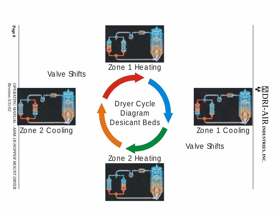
Dryer CycleDiagram
Desicant Beds
Zone 1 Hea ting
Zone 2 Coo ling
Zone 2 Hea ting
Zone 1 Coo ling
Va lve Shifts
Va lve Shifts
Page 9
OP
ER
AT
ING
MA
NU
AL
- AH
M-1B
HO
PP
ER
MO
UN
T D
RY
ER
Revision 3/31/02
DR
I-AIR
IND
UST
RIE
S, INC
.
S2
J1
2
D1
6
C1
1
C2
0
C1
4
C1
5C
13
D2
0
D1
5
D1
2
D1
0D
14
D9
D1
3
D8
D1
1
J5
Jp7
J2
11
J1
18
J11
J11A
U7
U5 U
9
U2
U2
A
S1
R36
OSC1
OSC3
OSC2
Rn7
OS
C1
R1
1
R1
2
R1
3
R1
4
+
+
+
++
C18
C13
C1
6
D1
6
C12
Rn
5
Rn6
INPUTS
Rn
7O
UT
PU
TS
R37
R38
Tb1
R1
R2
R3
R4
R5
R6Jp1
Jp2
Jp3
Jp4
Jp6
Jp5
Br1++ C18
C17C2
2C
23
L1
L2
Z1 C2
R7
R8
C1
1C
0C
1C
2C
3
C2
U3
U4U6
C8
U1
1
C15D8
D9
D0 D1 D2 D3 D4 D5 D6 D7
D10
D11
D12
D13
D14
D15
C4
C5
C6
C7
C9
C19 J5
R2O
SC
1
OS
C3
OS
C2
J2
U8
U9
U1
C1
0
1
2
3
5
6
7
4U2
Jp7
Rn4
Rn
3
U5U18
C14
Tb2
Smal l PLC03 REV E
8 UNUSED
8A UNUSED
9 UNUSED
9A UNUSED
10 ALARM (OPTIONAL)
11 HIGH TEMP. ALARM (OPTIONAL)
12 UNUSED
13 MAIN CONTACTOR/TEMP CONTROL
14 ZONE VALVE
PROCESS HEATERARID-X 50-100
Z1 TOP HEATER
Z2 TOP HEATER
TE
MP
SA
FE
TY
HI
TE
MP
PO
WE
R
DISPLAY BOARD - P/N 83401
MOTHER BOARD
PORT
DR
I-AIR
IND
US
TR
IES
EX
PA
ND
ER
BD
RE
V C
SS4
AL2
CR1
M2
AL1
SS1
SS2
110 VACFROM XFORMER
T1
50
14
UNUSED
# 9 TEMP. CONT SIGNAL
SAFETY
7 DAY TIMER
HI TEMP. ALARM SIGNAL
GROUND
L1
L2
7 DAY TIMER
C1
0
1
2
3
4
5
6
7
SS3
SS5
-
+-
+-
+
+
+
-
-
Z1 BOTTOM HEATER
Z2 BOTTOM HEATER
Z2
TO
P
Z1
TO
P
Z2
BO
TT
OM
Z1
BO
TT
OM
TS1
JUMP8
9
10
11
OT1
Z1 BOTTOM
Z2 BOTTOM
Z1 TOP
Z2 TOP
TS1
7 D
AY
TIM
ER
P/N 84102
.
Page 10 OPERATING MANUAL - AHM-1B HOPPER MOUNT DRYERRevision 3/31/02
DRI-AIR INDUSTRIES, INC.
Press Mounting
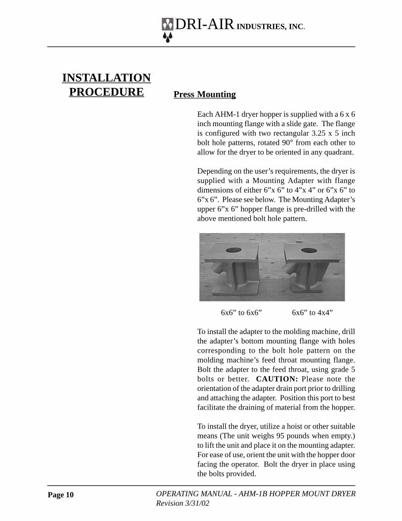
Each AHM-1 dryer hopper is supplied with a 6 x 6inch mounting flange with a slide gate. The flangeis configured with two rectangular 3.25 x 5 inchbolt hole patterns, rotated 90° from each other toallow for the dryer to be oriented in any quadrant.
Depending on the user’s requirements, the dryer issupplied with a Mounting Adapter with flangedimensions of either 6”x 6” to 4”x 4” or 6”x 6” to6”x 6”. Please see below. The Mounting Adapter’supper 6”x 6” hopper flange is pre-drilled with theabove mentioned bolt hole pattern.
6x6” to 6x6” 6x6” to 4x4”
To install the adapter to the molding machine, drillthe adapter’s bottom mounting flange with holescorresponding to the bolt hole pattern on themolding machine’s feed throat mounting flange.Bolt the adapter to the feed throat, using grade 5bolts or better. CAUTION: Please note theorientation of the adapter drain port prior to drillingand attaching the adapter. Position this port to bestfacilitate the draining of material from the hopper.
To install the dryer, utilize a hoist or other suitablemeans (The unit weighs 95 pounds when empty.)to lift the unit and place it on the mounting adapter.For ease of use, orient the unit with the hopper doorfacing the operator. Bolt the dryer in place usingthe bolts provided.
INSTALLATIONPROCEDURE
Page 11OPERATING MANUAL - AHM-1B HOPPER MOUNT DRYERRevision 3/31/02
DRI-AIR INDUSTRIES, INC.
Electrical Connection
The AHM-1 dryer is available in 110 or 220 volt,single-phase models. The 110 volt model issupplied with a power cord and grounded threeprong plug, while the 220 volt model requires anappropriately grounded plug, suitable to the user’spower supply to be attached to the power cord.
To connect the dryer to electrical power, plug inthe cord to any suitably grounded power source.With all units being single phase, blower rotationwill be correct.
Post-Installation Inspection
Prior to starting the dryer, inspect the unit to ensurethe following:
1. All hose couplings are tight and secure.2. Hoses are not crushed or obstructed.3. Process Air Thermocouple is connected.4. Inside of hopper is clean before filling with
material
INSTALLATIONPROCEDURE
(Cont’d)
Page 12 OPERATING MANUAL - AHM-1B HOPPER MOUNT DRYERRevision 3/31/02
DRI-AIR INDUSTRIES, INC.
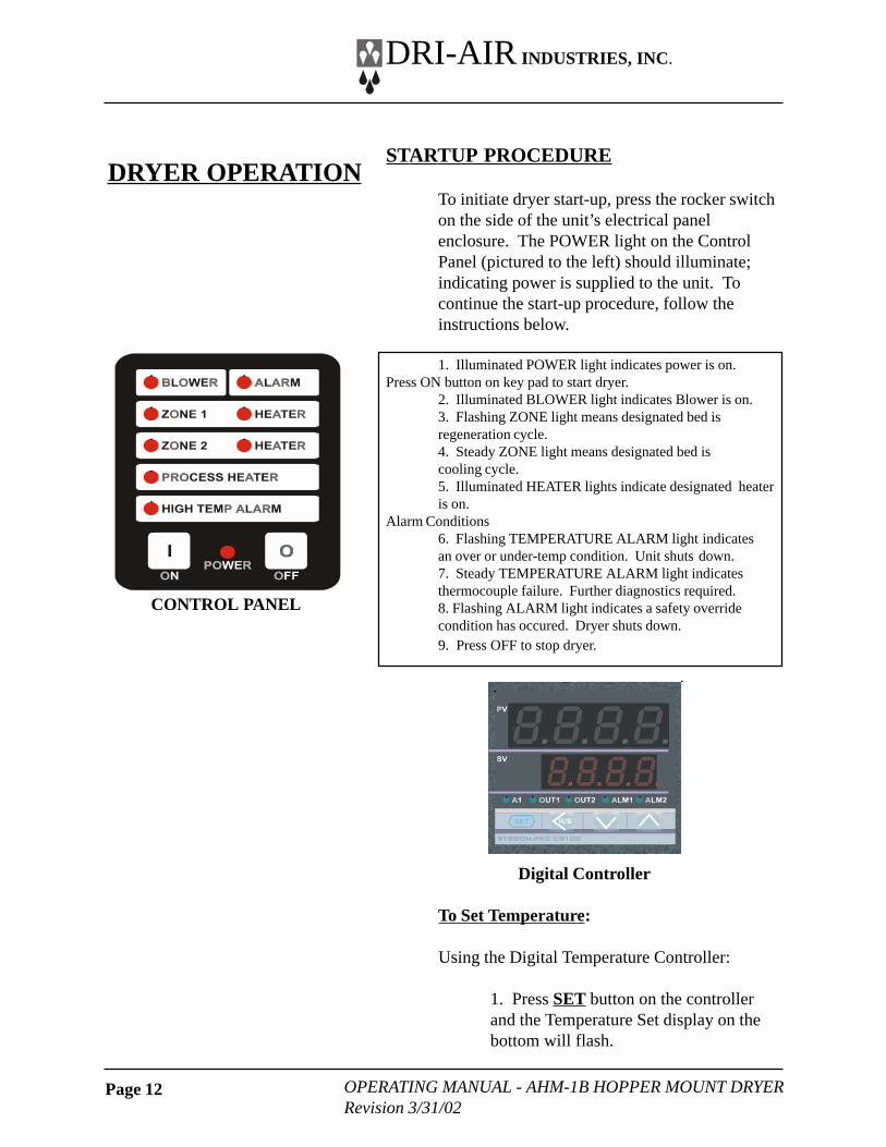
STARTUP PROCEDURE
To initiate dryer start-up, press the rocker switchon the side of the unit’s electrical panelenclosure. The POWER light on the ControlPanel (pictured to the left) should illuminate;indicating power is supplied to the unit. Tocontinue the start-up procedure, follow theinstructions below.
1. Illuminated POWER light indicates power is on.Press ON button on key pad to start dryer.
2. Illuminated BLOWER light indicates Blower is on.3. Flashing ZONE light means designated bed isregeneration cycle.4. Steady ZONE light means designated bed iscooling cycle.5. Illuminated HEATER lights indicate designated heateris on.
Alarm Conditions6. Flashing TEMPERATURE ALARM light indicatesan over or under-temp condition. Unit shuts down.7. Steady TEMPERATURE ALARM light indicatesthermocouple failure. Further diagnostics required.8. Flashing ALARM light indicates a safety overridecondition has occured. Dryer shuts down.9. Press OFF to stop dryer.
Digital Controller
To Set Temperature:
Using the Digital Temperature Controller:
1. Press SET button on the controllerand the Temperature Set display on thebottom will flash.
DRYER OPERATION
CONTROL PANEL
Page 13OPERATING MANUAL - AHM-1B HOPPER MOUNT DRYERRevision 3/31/02
DRI-AIR INDUSTRIES, INC.
2. Press the < key to move the cursor toeach digit you wish to change. Using the↑ key to increase the digit or the ↓ keyto decrease the digit, set each digit to thedesired temperature setting.
3. Press the SET key again to enter thenew temperature setting.
If the upper Process Air Temperature displayflashes, the temperature is below the preset lowercontrol limit.
If the upper Process Air Temperature displayflashes 0000 , the thermocouple is not connectedor is faulty.
When operating this dryer please follow theprocedures detailed below:
Hopper Maintenance
1. Always clean hopper, air inlet port anddiffuser basket prior to adding or changingmaterials.
2. Never over-fill the hopper. Material shouldnot obstruct the exhaust port at the top of thehopper.
Filter maintenance
1. Open filter canister and clean filter elementon a daily basis.
2. Change filter cartridge every 6 months(Sooner if materials dried are dusty.).
ROUTINE OPERATION &MAINTENANCEPROCEDURES
Page 14 OPERATING MANUAL - AHM-1B HOPPER MOUNT DRYERRevision 3/31/02
DRI-AIR INDUSTRIES, INC.
BASIC TROUBLE-SHOOTING
The following steps should be taken prior to otherdiagnostic steps.
1. Check the Power Circuit:a. Incoming fuses or circuit breaker.b. All dryer fuses. Each fuse (with exception of
main fuses) has a blown fuse indicator thatlights up if the fuse is defective.
c. Is POWER on light illuminated?d. Check heater continuity using a volt
ohmmeter.
2. Air Flow Circuit:a. Ensure Zone Valve position corresponds to
the regeneration cycle by comparing theZONE position lights on the Zone Valve tothe ZONE indicator lights on the controlpanel
b. Make sure that all hoses are connected, notcrushed, and free from obstructions.
c. Inspect filter and make sure cover is tight.
3. Control Circuit:a. Using the PLC Display Panel ZONE indicator
lights as a guide for the dryer regenerationcycle, check that all inputs are proper for thepart of the regeneration cycle that themachine is in.
b. Monitor the PLC output lights to ensure thecorresponding LED on the power board isilluminated and there is output voltage to theheater.
4. Operating Conditions:a. Check the process temperature. It should not be
set below 140 °F (60 °C) because the unit willgo into high temp alarm.
TROUBLE-SHOOTING GUIDE
Page 15OPERATING MANUAL - AHM-1B HOPPER MOUNT DRYERRevision 3/31/02
DRI-AIR INDUSTRIES, INC.
DETAILED TROUBLE-SHOOTING
Machine will not start: POWER light is not on.
1. Check circuit breakers (CB1) or incoming fusesinside control box to see if they are tripped orblown. Reset circuit breakers by turning themoff and then on.
2. Check small fuses (FU1 & FU2) next tocontactor. The LED will be lit if they are blown.Replace if necessary by opening the fuse holderand put new fuse into holder.
3. Check that incoming power to the unit is proper.4. Check safety snap disc. (Should be normally
closed)
ALARM light is flashing: Unit will not run. Maincontactor is not pulling in.
1. Check the inputs to the mother board P/N84101/84102. The LED for the safety circuitshould be on. If it is off, then one of the safetythermostats is open indicating a defectivesensor or a high temperature condition existsat one of the sensors.
Machine will not run: TEMPERATURE ALARMlight is flashing.
This indicates that the temperature has exceededthe high limit programmed into the temperaturecontroller or the set temperature can not bereached.
Press OFF and restart machine holdingin the ON button. Monitor the actualtemperature to see if it exceeds the set
Page 16 OPERATING MANUAL - AHM-1B HOPPER MOUNT DRYERRevision 3/31/02
DRI-AIR INDUSTRIES, INC.
point or can not reach the set point. If itcan not reach set point, see section below.
Machine will not reach temperature:
1. If the PROCESS HEATER light is not lit.A. Check output from temperature
controller and input to PLC.B. Check the Process Air Thermocouple.
The tip should be in the middle of thehose.
2. If the PROCESS HEATER light is lit.A. Check solid-state relays on power board.B. Check airflow through process air hose.
Check the limit first by pressing and holding theSET button on the temperature controller untilAL is displayed. The setting shown indicates thenumber of degrees over the set point that thealarm will be actuated. It is factory set to 50°F(30°C) and should not be set below 30°F (16°C)or it will actuate too soon.
If the temp exceeds the set point check the following:
1. Remove the hose from the top of the hopperto check airflow. There should be airflow outof the hopper exhaust port and a vacuum onthe hose. If there is little or no flow, checkthe inlet hose.
2. Inspect the filter to make sure that it is cleanand not affecting the airflow.
3. Check the to see if one of the power boardsolid state relays has failed on by using amulti-meter on the output to the heater. Therelay has failed if there is power to the heaterwhen the Solid-state relay’s LED is not lit.
Page 17OPERATING MANUAL - AHM-1B HOPPER MOUNT DRYERRevision 3/31/02
DRI-AIR INDUSTRIES, INC.
The Rotary Zone Valve is designed to providevery little flow restriction and no leakage. Itincorporates high temperature, self adjustingseals for years of trouble free service. Theelectrical controls are built into the end of thevalve and include position lights.
Trouble-shooting is easy. If the lights indicatingposition do not match the zone displayed on thecontrol panel, or there are no lights, the valve isnot working properly. See if the cam is actuatinga switch.
DO NOT PUT FINGERS INTO VALVE WITHPOWER ON
Check all electrical connections to make sure theyare tight.
Contact factory for a replacement valve P/N 83707with serial number of dryer.
The dryer control package includes a PLCcontroller that is programmed for the dryingcycle previously discussed. The display boardindicates the machine status, heater operationand alarms. See section on start up for details.
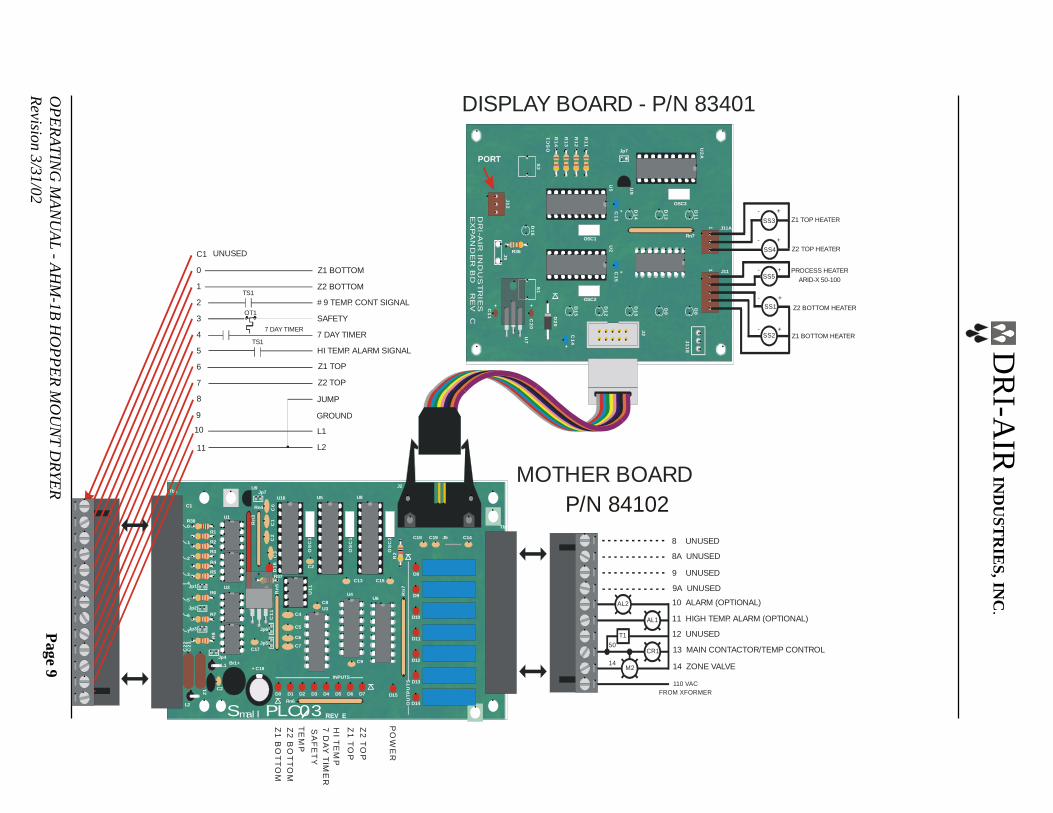
Inputs and outputs of the PLC that are used fortrouble shooting are detailed on Drawing #83542 enclosed with this manual. A lit LEDindicates the input or output is actuated. Allinputs are 12 volts AC and all outputs are 110volts AC and 15 volts DC to the heater relays.Refer to the electrical schematic for more detail.
TROUBLE-SHOOTINGROTARY ZONE VALVE
TROUBLE-SHOOTINGCONTROLS - PLC &DISPLAY BOARD
Page 18 OPERATING MANUAL - AHM-1B HOPPER MOUNT DRYERRevision 3/31/02
DRI-AIR INDUSTRIES, INC.
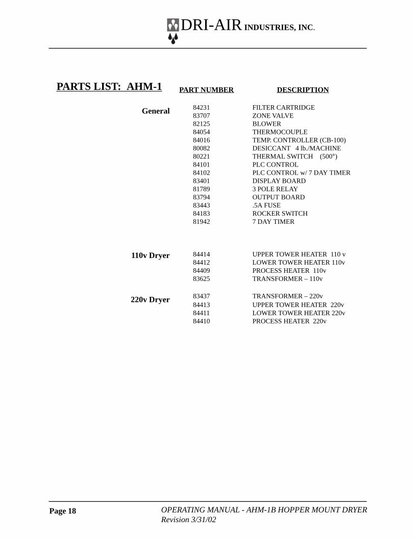
PART NUMBER DESCRIPTION
84231 FILTER CARTRIDGE83707 ZONE VALVE82125 BLOWER84054 THERMOCOUPLE84016 TEMP. CONTROLLER (CB-100)80082 DESICCANT 4 lb./MACHINE80221 THERMAL SWITCH (500°)84101 PLC CONTROL84102 PLC CONTROL w/ 7 DAY TIMER83401 DISPLAY BOARD81789 3 POLE RELAY83794 OUTPUT BOARD83443 .5A FUSE84183 ROCKER SWITCH81942 7 DAY TIMER
84414 UPPER TOWER HEATER 110 v84412 LOWER TOWER HEATER 110v84409 PROCESS HEATER 110v83625 TRANSFORMER – 110v
83437 TRANSFORMER – 220v84413 UPPER TOWER HEATER 220v84411 LOWER TOWER HEATER 220v84410 PROCESS HEATER 220v
PARTS LIST: AHM-1
General
110v Dryer
220v Dryer
Page 19OPERATING MANUAL - AHM-1B HOPPER MOUNT DRYERRevision 3/31/02
DRI-AIR INDUSTRIES, INC.
NOTES:
Page 20 OPERATING MANUAL - AHM-1B HOPPER MOUNT DRYERRevision 3/31/02
DRI-AIR INDUSTRIES, INC.
NOTES:
Page 21OPERATING MANUAL - AHM-1B HOPPER MOUNT DRYERRevision 3/31/02
DRI-AIR INDUSTRIES, INC.
NOTES: