
AHIII~l. ' From HDL-TR221 2Best · AHIII~l. ' ~Reproduced From HDL-TR221 2Best Available Copy April...
93
Ar AHIII~l. ' ~Reproduced From HDL-TR221 2Best Available Copy April 1992 External Com bustion Engine Technology (Vapor and Liquid Cycles) for Individual ýSoldier ~Power Systems by David L;-GOf1t~an JUL 15 1992 V U.S. Army Laboratory Command Harry Diamond Laboratories Adelphi, MD 20783-1197 Approved for pubiic release; distribution unlimited.
Transcript of AHIII~l. ' From HDL-TR221 2Best · AHIII~l. ' ~Reproduced From HDL-TR221 2Best Available Copy April...
Ar
AHIII~l. ' ~Reproduced From
HDL-TR221 2Best Available Copy
April 1992
External Com bustion Engine Technology(Vapor and Liquid Cycles)for Individual ýSoldier ~Power Systems
by David L;-GOf1t~an
JUL 15 1992
V
U.S. Army Laboratory CommandHarry Diamond Laboratories
Adelphi, MD 20783-1197
Approved for pubiic release; distribution unlimited.

The findings in this report are not to be construed as an official Departmentof the Army position unless so designated by other authorized documents.
-CitatioR of manufacturer's-or trade names does not constitute an officialendorsement or approval of the Use thereof.
Destroy this report when it is~ no longer needed. Do not return it to theoriginator.

REPORT DOCUMENTATION PAGE Form OomoOI OMB No, 0704-0 IMP Ou l t11g ul~ tl It" C0•10 of mbfisal `ft W t o` rode I hows M" 1q v Vie W IM 1or #&"a" OW" l e"Aru&A 4W8 OWW"1. WW end AW unvIaNn datai needed and CanI1Iebl Wn r*VWMM lg 00he W ofC6i aft ,mban Send ca0w*Il5 M96"d~n IhA b~ * or any 061. aioaW @1 M
Coleoan of m. mck~ng Iugecne Wor redig feburden, to Waatw'1 Nea9v Se .fOeorleate IW O oanWI 121- .w- nOaM my. Suite 1204, A-4302.VA 2 a2I=3o1)2 eOfe and Budgea . PapO Auc• • Pt 010f4-016 Wa on =C1 2=0C0
1. AGENCY USE ONLY (Leave bWtm) 2. REPORT DATE 3. REPORT TYPE AND DATES COVERED
April 1992 Final, from Jan io Dec 1991
4. TITLE AND SUBTME S. FUNDING NUMBERS
External Combustion Engine Technology (Vapor and Liquid Cycles) for PE: P62120Individual Soldier Power Systems
0. AUTHOR(S)
David L. Overman
7. PERFORMING ORGANIZATION NAME(S) AND ADDRESS(ES) S. PERFORMING ORGANIZTIONREPORT NUMBER
Harry Diamond Laboratories HDL-TR-22122800 Powder Mill RoadAdelphi, MD 20783-1197
9. SPONSORINGOMONITORING AGENCY NAME(S) AND ADDRESS(ES) 10. SPONSORING/MONITORINGAGENCY REPORT NUMBER
U.S. Army Laboratory Command US Army Belvoir Research, Development,2800 Powder Mill Road & Engineering CenterAdelphi, MD 20783-1145 FT Belvoir, VA 22060-5606
11. SUPPLEMENTARY NOTES
AMS code: 612120H250000HDL PR: 2R8A42
12s. DISTRIBUTION/AVAILABILITY STATEMENT 12b. DISTRIBUTION CODE
Approved for public release; distribution unlimited.
13. ABSTRACT (Maximum 200 words)
Soldiers of the future will be equpped with electronic and electro-mechanical hardware to enhance theircapabilities that will require individual power. There are several potential methods of supplying these powerrequirements. This report is an initial study of advanced vapor-cycle and liquid-cycle engine systems directed atthis application. Results of the study indicated that miniature external combustion vapor-cycle engines in the1- to 10-horsepower class, employing modem materials and design practices, have the potential to provide acompact, high-efficiency, quiet, and multi-fuel (especially military diesel fuel) power source to meet individualsoldier and special operations requirements. A major appendix presents a thermodynamic analysis of theperformance of a high-compression uniflow steam engine and the associated Rankine vapor cycle.
14. SUBJECT TERMS 1S. NUMBER OF PAGES
Soldier power, vapor cycle, engine, external combustion, steam, liquid, 96thermodynamics 18. PRICE CODE
17. SECURITY CLASSIFICATION 18. SECURITY CLASSIFICATION 17. SECURITY CLASSIFICATION 20. LIMITATION OF ABSTRACTOF REPORT OF THIS PAGE OF ABSTRACT
Unclassified Unclassified Unclassified UL
NSN 7540-01-280-5500 Standard Form 298 (Rev. 2-89)Prescribed by ANSI Sid, Z39-18298-102 4. i
ContentsPage
1. Background ............................................................................................................................ 51. 1 Soldier Enhancem ent Program ............................................................................................ 51.2 Power System Requirem ents .............................................................................................. 51.3 Sta.us of M iniature Engines ................................................................................................ 51.4 Arm y Engine Program ........................................................................................................ 61.5 Author's Relation to Project ........................................................................................... 6
2. Introduction ............................................................................................................................ 72.1 Types of Power System s ................................................................................................. 72.2 Internal Combustion Engines ........................................................................................ 72.3 External Com bustion Engines ......................................................................................... 82.4 W hy Revive External Com bustion Technology? ........................................................... 92.5 How to Revive External Combustion Technology ........................................................ 9
3. External Com bustion Engine Types .......................................................... ................... 103.1 Gas as W orking Substance ......................................................................................... 103.2 Solid as W orking Substance ......................................................................................... 103.3 Vapor as W orking Substance ........................................................................................ 123.4 Liquid as W orking Substance ...................................................................................... 12
4. Steam Engine Technology ............................................................................................... 144.1 -ypes/Classitication ..................................... . ................................................. 144.2 Status of Light Steam Power ............................................................................................. 144.3 Perform ance Potential and Resolution of Problem s .................................................... 154.4 Comparison with Evaluation Factors for Individual Power Systems ......................... 17
5. Vapor-Cycle Engine Approach for Individual Soldier Requirement ......................... 185. 1 System Block Diagrams.......................................................................... 185.2 M ission Profile .................................................................................................................. 185.3 Engine Sizing and Configuration.................................................................................. 205.4 Steam Generator and Fuel Tank Sizing ........................................................................ 215. O•t'hr C'1 2 1
5.6 Gcncral System Arrangement ...................................................................................... 225.7 Therm odynam ic Analysis ............................................................................................ 255.8 System Performance .......................................................................................................... 26
6. Liquid-Cycle Engine Technology .................................................................................. 286.1 Sum m ary of Available Inform ation .............................................................................. 286.2 Engine Description ........................................................................................................... 316.3 Advantages and Disadvantages .................................................................................. 32
7. Liquid-Cycle Engine Approach for Individual Soldier Requirement ........................ 348. Conclusions......................................................................................... 359. Recom mendations .................................................................................................. .... 37R e fe re n c e s ................................................................................................................................... 3 9D istrib u tio n ................................................................................................................................. 9 3
3

AppendicesPage
A . Evaluation Factors for Individual Power Syste!m s ................................................................. 41B. Excerpts from Literature oi Earlier Technology .............................................................. 49C. Calculations to Determine Preliminary Size of Vapor-Cycle Engine and Power
S ystem C o m ponents ............................................................................................................... 59D. Analysis of Vapor-Cycle and Steam Engine Performance .................................................65
Figure,I. Possible classification ol som e power systenm ................................................................. 72. H obby-type internal com bustion engine .................................................................................3. Example external combustion engines having a solid material as working substance ......... 114. Liquid-cycle heat engine 110] ......................................................................................... 135. Williams engine pressure relief valve arrangement .......................................................... 166. Vapor-cycle power system block diagram s ..................................................................... 197. Individual soldier mission--assumed power profile ......................................................... 208. Basic vapor-cycle engine configuration ............................................................................ 219. Preliminary general arrangement for vapor-cycle power system ...................................... 24
10. B asic engine cycle analysis ............................................................................................. 2511. Energy stream for vapor-cycle powered system.................................2712. Illustrations from Cleveland Pneumatic Tool Co. paper on liquid thermal engine ....... 2913. Heat balance and calculations for regenerative liquid thermal engne from Cleveland
Pneum atic T ool C o. report ............................................................................................... 3014. Schematics of liquid thermal external combustion engine ................................................ 32
TablesI. Individual soldier pow er- potential uses ............................................................................ 62. Typical hobby-grade internal combustion engine performance ............................................ 83. Contrast of external combustion power .,ystems with internal combustion power systems ..... 94. Vapor-cycle engine prelim inary evaluation ....................................................................... 175. Estimated vapor-cycle engine component sizes for general system arrangement ......... 236. Basic values and conversion factors ................................................................................... 237. Power system perform ance sum nmary ............................................................................... 238. Selected results from vapor-cyL Ie system analysis ............................................................ 269. Comparison of internal comnbustion, Stirling, and vapor-cycle power plants ..................... 36
!4
1. Background
1.1 Soldier Enhancement Program
The U.S. Army has recently initiated a program to investigate techniologiesthat could enhance ihe perlormance of tihe individual soldier of the fttlure.Possible materiel enhancements include elctCroic devices such as indi-vidual voice and data communications, navigation and display d(evices,night-vision and enhanced hearing systems and weapon rangiing and sigQ.ht-
ing devices, individual climatic conditioniii for heat and cold extremes:directed-energy weapons; and systems to enhance mobility and strength,such as individual equipment carriers or exoskeletal devices.
1.2 Power System Requirements
All such hardware item,; will require power fOr their operation. The elec-tronics items alone might be powered by advanced batteries. But the cli-matic conditioning, potential directed-energy weapons, and mobility- andstrength-enhanceinent devices, alone or in combination with tlhe electronicsitems, will certainly require engine-driven, or at least nonbattery-type powersupplies. I have given an estimate of such power requirements in tableThe specific values are subject to change, as the result of delailed evalua-tions being done elsewhere. Note that thl gloss powei levels ,equired fallinto two classes: an -I-hp class (assumr1ling. power for all electronics itemsplus climaltic conditioninlg plus accessory and conversion losses) and at 5- to10-hp class for exoskeleton or other mobility-c nhancemenlt devices.
1.3 Status of Miniature Engines
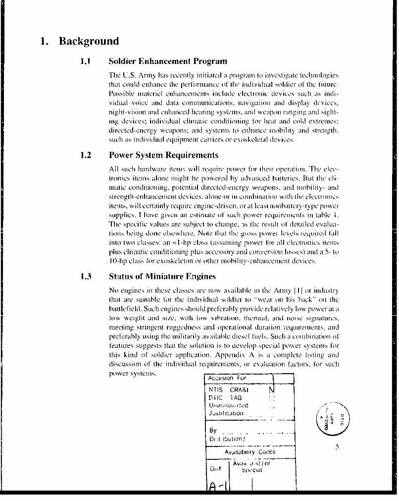
No engines in these classes are now available in the Army [ I] or industrythat are suitable for the individual soldier to "-wear on his back" on thebattlefield. Such engines should preferably provide relatively low power at alow weight and size, with low vibration, thermal, and noise silg llnttures,meeting stringent ruggedness and operational duration requirements. andpreferably using the militarily available diesel fuels. Such a combinationi offeatures suggests that the solution is to develop special power systems fiorthis kind of soldier application. Appendix A is a complete listing anddiscussion of the individual requiremenlts, or eval t ion faCtol'S. for suchpower systems. Accesion For
NTIS CRAMDIIC lABUnar;ioiuiced -
JuMdCJ b ll .. .. ..
By..................Di t ibution I
5Avjilibtiiy Codles
Avail a id/orOi-. 4 beC~dIDi-_t

Table 1. Individual soldier power-polential uses
I ' IatI led U £ti n :eed 1 ".st i mated enlergy I)ics':,- Welit I 'et Weight and11IIpowevr duty cycle (per day) CCqtIVk'alent olunlie
(pillts at(W) thp V (' day) (\tv-hr) (htu1) 251"; * Ob) (in. 3 )
1.Voice & data communicaition 2(0 0.(03 2(0 96 328 0.017 (1.07 2.1)?. SOIldier L-0tiputer 2(0 ((03 100 48(0 I .638 0.37 (0.34 10.013. Individual navigation 2(0 (1(03 00 .48(1 1,0638 (1.37 0t.34 1 O(14. Night vision (IR) &, 3(0 (1.04 501 3601 1,229 (0.28 (1.26 7.5
counter-SUrvet lance5. Enhanced hea~ring 10 (0. 01 30 72 246 0.t)r (((05 16. H-elmet display 20 (1.03 t00 48(0 1.638 (1.37 (1.3 4 10. 07. Weaipon ranging. 00 (0.08 3(0 432 1,474 (1.33 (1.31 9(0
sighting. & control8. Mie1OCl iMAtic 2(0( (1.27 701 3,30(0 11.468 2.58 2.41t 69.7
contdit ion ing9. Inldida kdI1,1Aic~ted. 411( (1.54 3(0 2.88(0 9.829 2.21 211W 59.7
enerigy wealponlI10. Mobility -enlhancemenclt 4(W9( 5.4 301 28,800 9zi.2t94 22.1 2(0.7 597
device11. Mattery rccltai;e N/A N/A A-s retLIi i red IncI tided inl liisIC - - -
p~owerlTotal of, item"s 1 -8 3,(1 (10.51t 5.760 19,059 4.41 4.1t4 It19.5
* Pint (sAl: mva 251,(' ellicieric y. atsminii tie I at 1 9.1(1( ht ti/lb. 7.5 I h/gal.
1.4 Army Engine ProgramTo address (his power- system deficiency, the Army's Natick Research.Development, and Engineering (RD&E) Center commissioned the Armly'sBelvoir RD& E Center (BRDEC) to conduIcIt -"Iroi t -end-s tiudy of potentialpower systemls th1at mlight 11C suitable for the future soldier s needs. Thisreport is at part of that study. A limlited level of effort1 andl at short schedule
prlevLelIId extensive analilyticall evalution01, SO the result is Some1whatl generalland Sub~jective inl nitwre. More timle to develop and Consult additionalreterolene mal'terialls ShOild (I prove a VialeI durine follow- on invest i Viations".
1.5 Authior's Relation to Projiect
During 1 96(0 the auth00or workd its at mechanical engineer for the Ui.S. ArmyTransportation Corps, conducting linvest ip:tions itt the area of-hI ohi steamvehicular power.'' During this period. I developed anl appreciation of thep)Oten"tial a~dvantages Of vaplor* and I liqud-cycle externall combustion1 ell-ginles. Md tiding their. potential for- cotuplacinless. quiet and efficient opera-lion, and ability to butrn anx' fuel. Somle ot the 110-itloratilonl used Inl thil, reporthas been taken ftomn refernceIC maliter'ial gleane1d frIn01 the I 'illh-Steaw- C I-projoct files atl that tithle.
0

2. Introduction
2.1 TJypes of Power SystemsMiany types of' power sys:cnis can~ be considered f'or individulal soldierapplications. One possible classification scheme is given Iin figure I. (Onetype not shown is the direct enlergy-conversionl systemns- -teormioelectric,thenifionic. and inaignetohiydrodynainiiiiic.) This report focuses on tile conl-InuLOUS eXternal comb11ustion enlgine tchnIIologies whereI- thle basic enlergySour-ce Is a petroleum-based liqu~id fuiel.
2A.2 Internal Combustion Engines
Small internal combustion engincs are availahkL now fromi thle model planehobby trade. They ilre inexp, nsix'e and thley, delivcr attractive vross hiorse-power-to-weight and size ratios onl thle order of' 1 .5 hip/lb ond 3 hpl/ini.3
displacement (see fig. 2 andl table 2). However, they have nminimal fulel,cooling, and other accessory systemls. they' runil Onl spcial fuel (alIcoho l adnitrometha-ne with oil added). they run at very hligh speed (10,000O to 30,000)rpmi). they are somewhat difficult to silence, and they are not designed forlong1-durati-Mon depC:.IdablC operation. 13R DEC is investig~ating thle necessarymodification and possible adoption of this enizine technology, Iin addition to
'wed-lmcer' tpeof wocyce asoline engine technology, for indi-vidual soldier power uses. Both durable (long-life) and disposable (shiort-I ife) 111interna l combustion enineII systems are being considered.
FElectr.iai FMechainicailI
F -la tter Gee7tr4 _ oout Pre-storedengine 1 t 1 -Gnmlr' eneigy
Ro~orv Priml F iternj I Propellanticomnbustion Icoimbustion ~ a
Liquid [ r oid Galvanic Fuel cell L echCo(yj Lqtiutfel
2 cycle. Recipiocating Spark[Vs Vs ignition Cas vapor Lqi oi
4 cycle rotary vs cycle cyclecylcclvs s compression (S;iriirg) (steain) ( etoi Ntn
conlinuous turbine ignmtioil- I
Figure 1. I~Possible classificatioin oft some1 pim)er sy stei is.
71
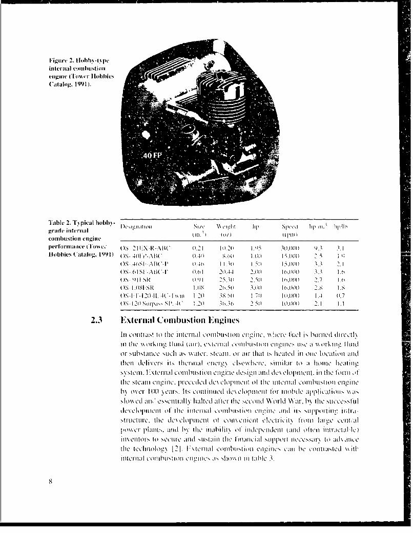
Figuire 2. II(JI)I) -tIili
Caitalog. 199I I.
Tab~le 2.1 'Ipical hobbi) - igrid itikrnidI w)'iI tljoll SI/i' c 11 ,,II p SlICk~t III Ill.' 111T,
combustion vniigiv n' 1u 1p
performnuhce? (i ms c.- OS II - K21-1AR13WC (1. I 0 2() 1.6 ."A(woo k).3 .IHobbies C'atalog, 1991) (),S 4 0 Ft AIi'-C .411 ,8. 0) I AU11 I IiO) .
()S-.408F--AIW -P ()1.46 I I . ) 1.,() 15111 . .105 681 l('I (.1 211.4I4 2.- (it)10.00 3.1 1.61
OS QI I SR 01.91 25. ' ( .211 1.()()( 2.7 1 -(O)S1I.0lSkS 1.118 2,.56 1.0t) 1 ("0(1 2.8S 1.8OS -Il- I - 2 1) 11. 4(C- I' i in 1.20 386) .1 10.00)0 .A 11.7
OS- 120 ShlrpaN, I')'P 4C :.20) 3T 1 10.00011 2.! 1.1
2.3 Externali CombusttJtion Eighiiws
Il OI~s.1 ti~ih'nl Colinsi t)sii 11)1I1,1cll-tS111 cIliZIIIC. \\wi- cr1c Iil P', 11111ni.'d drcin) the Nk 1lrkimW I ImuI~ (ai),) c\tcniaI com~butl\I)1'ion 1C enesusC. a \\ (lrkwll, I lind
01r .1lsthance such as \\dtcr, stcwnll 0 or air- that Is hicatcd Inl oiw loc'ationl andthen delivers Its therualh CoierC cIsL'Ic\\hc. siil to a1 home ltcatIni2
FXscm l. I 11r~a C0111l)Ltii onl en ).'11C dm.'Sii-'j .11d d( lcve lf )Illktlt- inl 111C 10111 Otthle stcafnt inlc. ccdcd dc\ clopilleill of li11C tticfIeital CoI1l'l tst I ol eneitiMw o\.Cr 10 wi(1yeaS. Its L'Ot1t1l)LICd (iC\CIOItII.'Il~lt tf l. il 1101 I)PiCt1~l a
slow med all"~ essentiially lulled aImSrtC scond 'World \Vifr. b\ t11he Ntil C ,sfll IIc\vClopnwnl~lt ol* 111C' 11Itlciltl C0111hlUstiI)I) cilgitle 11nd( its s1Ipportimn, intra[,,-
sruti-LCIIC. 1bm.C deVC10opmnent 0 ol \COO mel el .'lrll from~ lar!m.' ctiltial
lIo\\cfr plant"s. and bN Ilb' inablit11\ 0I itldelmcIlklenI kand often im11-Aradcta)inIVe.Iltors to sk.'CIIIC a1nld \sntelanI'll support ilcccssar\ to ad\ Inkce
the teclin1olonŽ I 2 . 1'I Ks terna combnsthujilt) m.mCimLm'If CaIll 1k' colittta'tm.d ýkiti'
ititerliail collht'lstotI m.thitlgm.' a,, sllO'.nin talle 3.1)
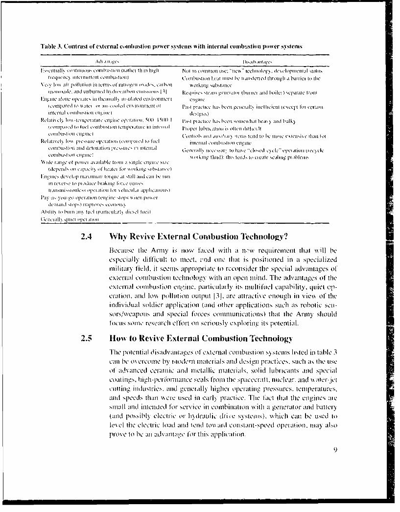
Table 3. Cotntrast o~f e~turnaI cumibIustiofl p~ower svistcrus with internail comrbus~tion power sisfernt
Athamni:qgcs DI )i';id' .itt
iLNNC[iii tlii eoitiriiiiiiii oil hii kih l l~jit (I iiliiithi hi-I lgh Not III commniti tiw:i -n: nc - tecfiti oloeý de'clopniocuil t JI~INtitreqiinc ) i cyii iliiiiittiiCyll IIIhIiti ' jll) Co'iitiltni oiii ficatti iiiu'.t 11C IlnI motc cd through a haliiiic to [lie
VCV Ill% MIr poInII1,10 III I1in 01-u of109I 0il o 1do\Rc. cadlIl kin i king m~ihktaiicc
itioitO\jthC. Moh nid rii h111111C [Vdie.a htOii CIIIiis1.toi1 Repiti'qwc. ,tcamun ciicrloi (huiutci and hIojilc I sparate I tnim1:i1 tteti1 iii opet11 O diMC' InT IhtCIrII~ihI) Itito lted Cmiili miiit't ciii
(CoIIIpItI'ih lit) %\;Iti.'i (Talit ii*O~iid milXiiililCIII it0 hI~Ii jiraICIICC IMi I'een 1cri 1C\ i CICI t (C\ii C we t 101 Ceria 'ii
Meail\ e I0\ i\ -teiiIPCrIMiCit Ci.igHii i t 'll. 5W1(1 SM0( 1 P,111 pi)M I 1e1eh,1'. hi-:Ce SII I\ s IiIe h iti; )ia y Il hn i b lk)(iii id t ) e ii o el ciiiitbii A illo [Cie i aiipiine III ititclia tttI iii J ItiI'iik;Il jot P, ofteni dilfficutil
eiiiiiblimiol QlI igtneC ('0i INii ils dtitiii i 'ICItI'. t~ld It' hiC iiii1C C.XICIOSI\i. it~ltj fltRCeiitvek Io%\ -p1 c.Nuic opet iiilot Itoilp;lI ed 10 Iloch riicniiai iitiiu- igit cign
Colihiiiicion muid deliiinaioiil prc'NI,so III inliter ti'lI (CicIialk llc'N. iiCst) toI\ -kJve k e hsedeCIe' oper 1 ([CC on ICe iColiibiisitlOri CTIJInIIC) A~oikinig t~mi.); t'III[ fleds to cicaice sixiling piAiIe IIs
W~ide tangle oh poiwet 'ivtiillealI hlil out. sinigle ClIglille oleChiepontiNh on vapacii\ of hicaici fOr \kotkinki5 sihisidrrce
Iliii eve. e k~:Cto Ptotiec111,1 ht :ikiii at iit tilaves 1heItl
III i:e,itt itii ,~iiN p iot~uci tmifw tot \CiL t~t, ihhl:i~
I'md -ti'- \Ot -oilIl kipiat Ott (enlgitte s op' V W It P)it e
Gene hi hi quiet opci itioni
2.4 Why Revive External Coriibistioii Technology?
1ecauILse the Army IS nIow laIcd With 11w requirement that will heeSPeciaIlly' difficult to meetO. ýIld oneC that is Positioned InI a specializedmu ir1ar)y ficid. it Seems appropriate to) rccolisider' thle special ad~van~tajges ofexlerrial Coll] ustlonl techlnology with an open mnind. The advantages of theexternal combustion eriine, particularly' its multi fuel capability. quijet (\p,-eration., and low pollutionl output 131, are attractive enough inI vie,, of theIndividual soldier appli11cation1 (and other applications such as robotic scn-s ors/\veapotis and Special for~ces communlications) that the Army shouldfocuis somec research efT~rt on Seriously Cxplorine~k its potential.
2.5 How to Revive External Combustion Technoicogy
The potential Oisadvanitages of exirnal combustlonl systemls I isted in table 3canl be oNVercome1 by r 11iodern'l mater1iaMlsad LICSIC0it praýCt:ces. Such aIS thle uIseof advanced ceramnic and r11Uctal lic mterlials, Solid lubricants and specialcoa rIII. huih-performiance seals from fihe spacecraft. nuclear, and wkaler-jetCl~tttin g indutriL1-es, and gncraC_1ll ly igher1 oprt rgI eSSure-S. temlpetattIr-S.arid speeds thanl wcrc usedl InI arly' practice. The fact thaI-t the eniginles aresinIMI and intend~ed for service InI combination w\ith a generator and battery(and possibly electric or- hydr1aulic driveN~ system s). whichi can be used toleX el the electri-C loa1d an1d tenld to`k`,ard con~stant-speed operaimon. mlay' also
roveCt be 111 a1dvantage forlf this aplplicationl.
9

3. External Combust ion Engline Types
There ai Glutou baic typcs of externail comb;ti,1onl ClItwI ics. chasslied ac-nilditig to theK working Substance tINCed: vmis.por, liquid. Mnd solid. An -
otherI type., 10 not\111 ha in S1,a 0haftioutpu and 10t co1nsRidered herC. u1Ses arl'electocal lv char-ged aet osol as the wonking toed itin 1141.
3.1 Gas as W~orking Substance
Thle Stilfllý iCMC-1 extrn llcobustion power system11. niamled lot1 the Scottishinventor. of* its Ii igli-Cfic ienicv t herodtio iccyl, is (thc primar11y exainpll*Cthat uses cas as, aworking Substance. G3sis atiltractive &, at workw incluid IIIthat iH is ielativ e ly easily hand led (wth in cmcine ) and does not havecappreci.able low.-tcipc-rature Storage and starting problems. Anothler advan-tarc Is that It is reclat i\'Cl) easy to make the power. system operatc III anlyaltiftude. Potent6ial dki sd\ antiages of using, a gas as a1 wkorkm- iflu id are thatieclatik, clv hmte quanlt itics nleed to be tranI~Sp)orteC l.nd he0.1t tranferis rela S -CItively le- s efficient than I or tle other tN-pe;s of' wor-king fluids. '11hs thleenocine system ls pumping" anld heat transfer. comlponents. tend to be some-what bItl k\. Al so. i-,ascs suceh aS blell.1 i' d 'to Nt LCI Ivdo .e aC desNired lo0titliipO\CL edperorman1llce. and their use '-es!ak-proof' seals inanda1-tot y.N atic:k R)& I: Cen~ter is curren-Cltly expi 1m1. mmture trece-pistonl S-dirl inc
Mechanical T!echnloho'-y. In1C., of ILatham. NYV. N at ick w\ill report on thlistype ofeternal-1.1 Combustion techniolopy, So it Is not disc'ussed furither InI this
3.2 Solid as Working Substance
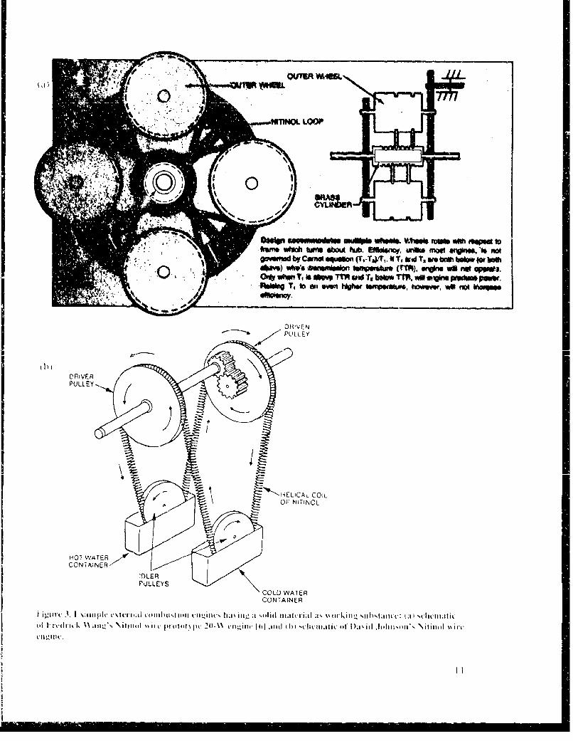
At the other end of" tIIl, ýkorkinz csubIstanlce spedt'Lil r 1um ae t~i cis that1 ulse atsolid aIS the I teati-1ranstet meium(1111. The pImat e1WI CVample1 is en01C cines mdeusinei N itin tI memory metal \\ Ives or stinps. Many di iterent conttfhprat ionls
MIMIC cyVCls. inludin~g the Er1icsson ~le (NCotsatpesueh ex.cli nigesC) or the St iirrie-, cycle (osato lum hat exchang~es). Tvwo cxi-Iamlple enginie concepts are shiown In i cute 1. Adt antaoes of at Solid wvotkinguSubstatnte are thle absence of, fluiiids: PC~ilU 1e0 i i te seaIled, and sHimph ic i\ o1,
to Io~ o\\ p~er dsty)and reclat i\CIy low thermalil "Ifficienicy: iboiut 10,pv"eren alt best. especialk al atk thehimited nIater-i'll St rains neceded to pieser'\ cduraibilIity'. BecauLseCi.tI mle sil!n i ficanti dilSad vantagesof uS Ot'U a.soid wORIork iiilsubstanlce with respect to thek r*CLuiLeIenCIIt s fum n m iv idu" ' IVII soldier- power,"sNte, hIs tp of enIn is not reconlitnendeId f'0r 'FuttIerin:et ct o
and Is llot di seitssed, fur-ther.
I10
Ermi Oft ebwA huW i~* b. 8Sa"eno, unike mootaV~ wW -f fwtogovemud byr Camo o**Win (Trla)/ri * T, Wd~oi'i wea br~h below Wr both
*0 -40%m) w~s 0awnlimilAof kapenikas altT, .Vkw we r* MVt*O* Whemn ToitOM Trh MW Tv belu rFl. will sviS Wom* pmv.
Abiftn T, l m wmn Nowe tsnpipormw, towvvw, wel fo WVMw
1) IVE N
~N~ELICA COI
"H01 WATER ACONTiAINER-"-
'r)LERPULLEYS
COLD WATERCONTAINER
vIII p~ . 1,11 m ll ll~ i(ll I t-N 11 1 il'-' %(1 i

3.3 Vapor as Working Substance
When vapor is considered as thle working Substance, thle primary example isthe steam engine. (Some engines have also used fluorocarbon-based andothecr working fluids.) Vapor-cycle engine systemns generally operate byconverlimig the working substance between its liquid and gaseous formi. Thisallows f'or more compact pumlping, and heat-exchanger components thanWhen at gas IS used1 as the working substance. Water vapor particularly isreadily availiable, highly characterized, and gcnerally tractable, ats demon-strated by its long and Succes;sful history of application. Disadvantages ofsteam ats at working substance include poor lubricity, problemis accommilo-dating engine operation at below-freezing temperatures, and thle need toMnana:,e the hecats of vapori/ation and liquefaction when thle working sub-stailtce is constantly converted back and forth between thle vapor and liquidStatos.
3.4 Liquid as Working SubstanceVery few engines have been dlemonstrated that use liquid as the workingpsubstatlce. Anl engine patented by W. B. Westcott, Jr. I 101. and demion-strated hy the Cleveland Pn~eumatic Tool Co. around 1958 to 1960 (fig. 4) Iisthe nma .or example I have found. It is based on compressing. heating. andthen expanding at liquid substanic: tmie as. aIioi it l 'p;
bihiity 01f liquids has lon- been used to advantage in springs for aircraft
laningzer and punch press operations, 111 1. Thle advantages of' a liquid-cycle based enigine are LOrnlpact size because of the highi working pressures
working Substance. efficicilut hcat tr-ansfer. and suitable lubricity (for certainliquids). The mla~jor dfisadvantagc is the high working p~reSSUre (10,000 to30.000, psi) and aso;ISakt1Cd high-performance seals needed to achieive ad-eqUatC Compr11CSSIOn1/0xpaillion0 ratios.

Figure 4. Liquid-cycle 33'heat engine 101].
2 14, 1 7 .9 7168 19 6, ,3
7 233 2
91 9 7 3
34J
IAL Force on riiht of piston 23 B
r "I
•FORWARD STROKE -.4--REARWARD STROKE
PISTON .STROKE
13
4. Steam Engine Technology
4.1 Types/Classification
Hundreds of different configurations of steam engines have been built overthe last 200+ years i121. ' hese include reciprocating, rotary, and turbine(steady-flow) units. Reciprocating engine designs include single-cylinder,in-line, vee, opposed-piston, and free-piston arrangements operatini. on"two-stroke" cycles. Steam is expanded in a single cylinder or multiple(compound) cylinders, using pistons that are single-acting or double-acting(pressure applied to both forward and reverse stroke). Compound units mayreheat the steam between cylinders. Steam has been admitted through slide,rotary, and poppet-type valves, and exhaust can use th1e uiflow (exhaust atbottom of stroke) or the counter-flow (exhaust at top of stroke) principle.Exhaust can be discarded ("open-cycle'" as in railroad steam engines) orrecovered in a condenser ("closed-cvclc"). Exhaust condition.; can be con-densing (mixture of water and vapor) or noncondensing (saturated or super-heated steam only).
Condensers include vacuumI units to allow additional expansion or eiiergyextraction, atmospheric pressure units, and units with regeneration to tralls-fer waste heat to the boiler feed-water. Boilers to generate the steam havebeen of ihe fire-iubc typ- (ais in railhoad aid dwc SlitIcy sih[Lii Cll , 1dILS1and water.tube type (as in central generating stati ns and more miodernvehicular steami engines). Bailer circulation can be by natural convection orforced by pumping, as in the once-through "flash" boilers used in vehcular
light steam power plaints and some domestic hot-water heaters.
4.2 Status of Light Steam Power
Except for central power-generating stations and power plants for somet,large ships, steam or other vapor-cycle engines are rarely used today. Thep ...... ,., , ge.. , of. , t.a.. povw,er oIlr dern co-m -- ,-ec'l '+'hi,_',,l,,,
applications arc far out weighed by the disadvantages of attemlpted competi-tion against the deeply entrenched and highly advanced internal coiInbustioiivehicular engine technology. it makes sense to consider vapor-cycle tech-
nology only for special applications, such as powker for space platforms andnew military systems. The individual soldier power systems are just the typeof application where at void exists in engine technology, and an open mindcan seek fair evaluation of all -ippropriate alternatives.
A review of past mobile steamn power practice reveals that ste;inl lost out todiesel and electric propulsion for rai*lroads because steam locomoliive powerfailed to modernize in a timely manner. The 1irC .tulle 1.boilers CemployCd LIp to
14
the very end of the era could not operate at the high pressures and tempera-tures required for efficient thernal pcrlormance. The Doble and Whitesteam automobiles and the Bessler Corporation's steam-powered aircraftdid use forced-circulation water-tube boilers, and they advanced mobilesteam propulsion to a fairly high level. The Doble car was noteworthy for itsrelatively highly developed automatic control system, and Bessler wasnoted for his efficient and lightweight boiler designs 1131. However, thesecompanies also did not modernize to the extent necessary to compete. Theyfailed to employ the highly efficient unillow [14.151 engine design practice(see the excerpt from Barnard et al 1121, app B), similar to the U.S. auto-makers' recent failure to employ, in a timely manner, the multivalve percylinder internal combustion engine technology advanced by Japanese auto-makers. Ayres and McKenna have written an excellent book I16] coveringall varieties of vapor-cycle engines and other types of potential powersystems for vehicular applications.
Perhaps the closest anyone came to being competitive in modern vehicularsteam engine technology was the engine developed by the Williams EngineCo. of Hatfield, PA, between 1932 and 1970 117, 18]. T'he Williams engineemployed high-pressure (1000 psi) and high-temperature (1000°F) steam,geineraited in a rnonolube flash boiler. to drive a hitzh-comprcssion, unitlow.single-expansion, noncondensing, multicylinder, poppet-valve engine athigh rpm (set- excerpt from Wise 1191, app B). The uniflow engine pressure-volume cycle is similar to the air-standard diesel thermodynamic cycle.wherein residual exhaust steam in the cylinder is isentropically compressed
to boiler pressure and high temperature, thereby providing ideal conditionsfor preserving (and perhaps increasing) the energy in the incoming steam. Apressure relief valve built into the cylinder head of thie Williams engine (fig.5) is used to regulate peak pressures, and direct oil injection in the cylinderwall is used to provide proper lubrication under the high sICanI temperature .
conditions.
A four-cylinder 56-in.3 Williams engine, used to power a city bus throughthe hills of Pennsylvania, reportedly gave better performance than theoriginal internal combustion power plant. Various lab tests of Williamsengines have supposedly given thermal eff'iciencies in the range from 3(0 to38 percent.
4.3 Performance Potential and Resolution ot' Problems
The Williams high-performance engine technology is suggested as tilestarting point for the design of mininiattre advanced vapor-cycle power plantsfor the Arny's individual soldier power ipplical itos. It is expected that highloverall system performance can be sustained hy ( I ) cnmploying high-speed
15
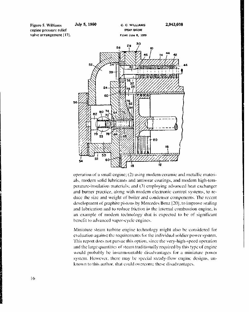
Figure 5. Williams July 5, 1960 C. C. WILLIAMS 2,943,608engine pressure relief STE ENGINE
valve arrangement [17]. Filed Joe 8. 1959
N "46 t4 4 42
S242
operation of a small engine: (2) using modern ceramic and metallic materi-
als, modern solid lubricarnts and antiwear coatings, and modern high-tern-perature-insulation materials; and (3) employing advanced heat exchangerand burner practice, along with modem electronic control systemls. to re-
duce the size and weight of boiler and condenser components. The recentdevelopment of graphite pistons by Mercedes Benz 120]. to improve sealingand lubrication and to reduce friction in1 the internal combustion engine, isan example of modern technology th~at is expected to be of significant
beniefit to advanced vapor-cycle engines.
" ~Miniature steam turbine engine technology might also be considered for
evaluation against the requirements for thle individual soldier power system.I.,'Ihis report doe2s not pursue Ibis option. since the very-high-speed operationi and the large quantities of steam traditionally required by this type of engine
would probably be insurmountable diisaidvaiitages for at inniature power
systemn. However, there mlay be special steady-flow engine designs, un-known to this au~thor, thatt coildi overconm._ these disadvantages.
1 6

4.4 Comparison with Evaluation Factors for Individual PowerSystems
Table 4 gives a preliminary evaluation of potential vapor-cycle enginetechnology against the individual soldier power system requirements orevaluation factors from appendix A. The vapor-cycle power system isexpected to meet or exceed all requirements, though it will probably beslightly more expensive than an internal combustion engine solution, andspecial design and operating practice will have to be used to meet the all-attitude and cold-temperature requirements.
Table 4. Vapor-cycle engine preliminary evaluationFactor Proi, CoIns
Cost Developnient costs expected to be little differerit than for ainy ne•-. hlbodtitioti Costs expected ito bc somllrewhatmiiiiattre high -periornialiec duit ae cligilite systui i. hi gher than for internal coibiisttllonMaintenance ctsts Imlay bie slightly less because ot denoiistrated eng1ne becatuse of cost it stearnlong lift sll eall cngite. gieLiealor. specivii! c0111t ol systell. and
special Inaterials. Overall. estltllnle I S-
20% preniuno for this technology overinternal ct-onbhstlon engine.
Weight Weight of Ihis high-perftorlnance engin le system " expected Io be Steel w ill be basic l/Mist Iit l tiiiitaterial io it)competitive with other techniologies of equialkto low noise get durability atid perffotilance at highand diesel fuel perfoiialntie'. Estitn:ited systemn weight tetirperalures and pressures. Not a;sd(nluding fuel) for 24-hr op-.eralion at 166 W avg. power is ý2ll lightlweiglt:t as air-cooled aluinliu'nllIll. llodel ailpialie engines-
Signiature: Noise is expected to he small I for cquivalent suppressionl because Infiared signattirC is expected it) be equivalentnoise extemal coinbustll systels aftre inhterent I, quilie tts arte 'liotnit to oilier engine systetus it that theclcctronmagrietic hc'i-dog systeNl,. Electrotnagimet ic giaturc i, expected itl be overall thermnal efficiency is smiler.ittfrared slight in that there is no Ihtlth-v:lhage continuoius ignition Peak engine teliperat iires are relativtlyvisual system required after staritip. II gI'-efltcuenci,.y cotibtistiont will low. but COUlbtioni teiiperature is
give exceptitinally clean e.halatst. :,imilar. Signature will he higher than for
hatte'ry-only sstcll.
Safety Air pollutaunts front external cotnthustion systemis are the lowest ti'el- ciinibutioii tenr.er-ature aid exllaust ateachievable Pressure of wirking fluid is not dangerious bccause sinil:u It' alny cnigiie .".s'cll. -itol
of except itonallyv stiall volume anld packaging shitlding. surfaces will have shields and guards.
Vibration, Opposed-piston engille designt is intlerently balanced it) high degree. Vibratuio alLd g)-io forces shoulu I"h hi'gyroscopic forc•s All conpi Ints ai Cxcry stallI and speeds are tnoderate for negligible. though niore thit Ior a
engite of this site. battery-only systeiul.
Attitude Expected to Ibe atienuable it) opet ation at any atlitude. as is utrinal Design Ihir operation it any attitude isfor aircraht engines. expectCd ill be" diihcuillt.
Shelf lite IHigh grade ntaterials should pe.,nit indefinite storage tiune withoul Fuel, oilI. tiid t tler will be required to befluids. inslltalled upoun issue.
Integrated logisties Special fuel is nitl required: diesel is useth. Sy• steti will be designed Ronutinc tmainltenlallnce will be tteedei as foisupport fur a long life as tradlittonially themtonistrated for steani pziwer any etngitie :; Destein. Detailedt
sytellN Low cost aitd sttmall size will pelitiil easy tItCi ii Mid metnatliian/nlallen'i Iiiual slho Idexchiainge 'if detetlive uiuts. perinit all) eingin.c titechnlicti ti service
Relablility/ Maintenance inantuit etill be stilied in soldlier's conllllite. Steaiti Pilot light will be rcilUiredil t protect againstavailability/ eng•lies are I tridliotttily T ugged and upciate fir liutig lict iils i rt'iiezig telllperatures. btll allmaintainuability without mainteniance. co'npoi'nls except cotudeiser are
tihctlalhlx ilinuiatcd.
Size A htigh-perfiomtance engitte systeti is expected to, lit iti a shiie-box S wii will ptobably not be as sitall as itsilze %tluille tul -(0. ft 1. Patc.kagitng will lirovide case oif dispoisaile illildel aii platie iiginte.
handhling and use.
Start itg/restartitug Startlltg will ic autolittict at tlie ie o a lit billitn. Rstatanhg •x will 'r'licr pivtuti h tenlliprtcuiraUic for Iill loadbe autollmatic, just is it is hor litnitc heating systetils. shutild be reached iti about 5 - 10 seconds.
Efficiency This is all efficient engine system:ý expected therntal pcrforniancc is Hligh teuip,rl-atues and picsslues ( I(XXt'IF,similar to that of a hign-perfotaltiane diesel engine. Nolinal I211 2 p,it are required for efficient
fuel consumption is ext tnated at less thin I0.103 gal/ht. opertttioln.
17
5. Vapor-Cycle Engine Approach for Individual SoldierRequirement
5.1 System Block Diagrams
Block diagrams for a1- steam plant or individual soldier power use are shownin figure 6. It is assumed that a.i motor-generator would be used for enginestarting/restarting and electrical power production. ft also serves as theengine flywheel. The system battery would be large enough to meet allsystem power requi ements, not only for engine staiting, but also for alloperations. icluding driving the refrigeration compressor, during periodsof up to a half hour, whenever "silent" and low-thermal-signature conditionsminist be met. It also serves as the major load-leveling device to accomnmio-date needed power surges and other transient requirements. The refrigera-tion compressor fo, cooling can be driven directly by the engine to save an.additional electric motor and improve efficiency. A modular arrangementhas been devised, wherein the compressor or other auxiliary items can beattached externally. as tequLlired by the mission.
The blower is assumed to fulfill the air-handling requirements for thecondenser as well as the burner. The control system box includes all sensorsand actuators that woald be required for fully automatic control ot tIMevarious pressure, temperature, and flow-rate f'unctions. A feed-water preheatercomponent (probably part of the condenser) is assumed to provide recoveryof available exhaust heat from the engine. An alternative approach to wasteheat recovery (which is not considered further in this report) is to employ aminiature exhlaust-driven steam turbine to power some of the engineaccessories.
5.2 Mission Profile
Preiiminary rcquircilm tnis fi ul ,ILIMA " uua•i ....l I , i- .. ,lU, , :.. .... .. ',,LdIIIL*...from BRDEC, are ,hown graphically in figure 7 for a nominal 300-Wsystem having a 25-percent overload capability. (100- and 700-W syslemsare also suggested, but the I00-W requirenient can probably best be handledby batteries, and the 700-W requirement would b," a simple extension of the300-W system.) The avcrage power anl1{d cumulative energy requirements for6-. 12-. 1 8-, and 24--hour mission scenarios are also shown, again ;aSSum111in1g
the nominal 30( -W system.
41
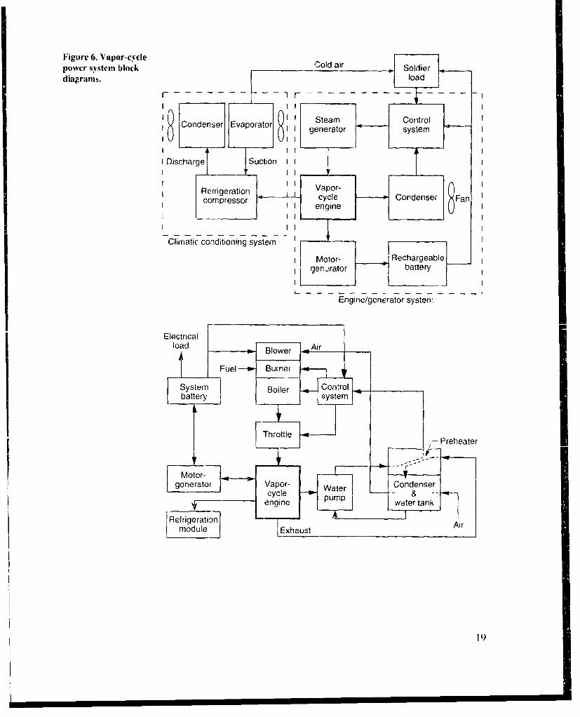
Figure 6. Vapor-cycle -l ipower system blockSodediagrams. la
8Condenser Eaotr8 gSteamCotl
I Discharge Suction II
Reirigeration cycepCodesecompressorocyl odne Fa
Climatic conditioning system
I Motor- Rechargeable
Engine/generator system
geneato VapBowr- Condense
RI r I Fulr-b- Buine
s s19

Figure 7. Individual (a)soldier missioln-- 400-assumed power profile.
350-
300--
250-A
6 & 12 hr avg =200 W0 18 hr avg 175 IN
0
150-24 hr avg = 166W
100-
50--
0 - i-- - - ----
1 2 3 4 5 (3 7 8 9 10 11 12 13 14 15 16 17 18 19 20 21 22 23 24Time (hr)(b) 4
3.5-
2.5-1-
0 12 18 24
Time (hr)
5.3 Engine Sizing and Configuration
Appendix C (sect. C- A) shows how engine size can be determined based onassuming a peak output capacity of 375 W, a motor-generator and refrigera-tion compressor efficiency of 70 percent. an engine speed of 9000 rpm, anengine accessory requirement of 100 W, and an engine mehanical efti-ciency of 85 percent. These values result in an engine indicated power of 1.0hp. Compared to efficiency assumptions discussed later (see sect. 5.8), thispower level is expected to be conservative by about 25 percent. Volumetric
20

sizing of the engine depends on the indicated mean effective pres'urc(1MEP) during the engine cycle. Vf an IMEP of 100 psi is assumed (hascd ontypical practice). an engine swept volume of 0.44 in.3 is obtained.
A two-cylinder opposed-piston engine configuralion, having a commonsteam-admission area. is proposed to obtain good conlrol over the highcomprcssion ratio desired (=30-35 to I ), to consolidate the high-tcmpera-ture portions of the engine for best thermal Il1nlageleCnt, and to provideoptinmum balance of reciprocating forces. The resutIt is ia engine bore of-0.75 in. and a stroke for each piston of 0.5 in. Based on conventional internalcombustion engine practice, an engine of thi:; size should not have anyproblem attaining the 9000-rpm speed requirement.
A full-scale layout of the suggesled engine configuration is shown in figure8. Ti, "'cross-head' piston configuration allows Ifor the high-temperatureceramic or graphite piston crown to be separated from the low-temperaturesection attached to the lubricated connecting rod. The two pistons aresynchronized by means of four spur-gears, ahllough a high-performancebelt or chain might be considered for this fUnICion during detailed design.All gears are shown as the same size. but they can be made different sizes ifneeded !o drive auxiliary ioads at higher or lower optimlum speeds. '[ecentral engine component is about 1.0 in. in diameter and 5 in. long. Its sizewii', umczease when the valves. ,nlet and exhauLSt manilolds, and certainaccessory items are added.
5.4 Steam Generator and Fuel Tank Sizing
Preliminary sizing of' the steam generator (app C, sect. C-2) is based on anassumed engine thermal efficiency of 26.5 percent, at boiler efficiency of 87percent, and an excess boiler capacity of 50 percent. Norially. detailedthermal calculations would he done to determine tile boiler size, buit a
Filg-r,. S.. !.-1,7ae,- :_ . ,_. . • . .cyce engine .Configuration.
il121/" "t Q77) / t- W :w: "J I-- -
K- -4.2 in." L
21

preliminaty estiniate is obtained fromt performance parairietcis reported bythec Bcsslcr Corp-oration 113]. at comipany known f rom iic 1h 930's f'Or thecirgood monotu11.bc boiler dIesigns. IBessler reported demonstrated heat rates of'1.25. 2.0, and 3.0) million btu/hr per cubic f(oot of i_)0iler VOIlume. Assumingat value of' 2,000.000) btu/hir/1`t3. at volume of' 14 inl.3 is obtalined. Furtherdoubling the volume to accounlt for the smiall-size plant yields a steamigenerator size of' 3 inl. inl diameter and 4 inl. long. Peak steamr rate isestimiatedi at 9.6 lb/hr. which allows for vapor-cycle thermial efficiency to beats low ats 17.7 percent.
I arrived at thle preliminary sizing f-or thle fuel tank (app C. sect. C-2) byassumning 033 biu/in.3 of diesel f-uel-, and an average daily pow'er rate of' 166W. These assumptions yield at taink size of approximiately 1 86 in.3 (6 x 8 x3.9 in.). holding 0.8 gallons.
5.5 Other Components
Table 5 lists tile various componentIs assumled for at general engine systemiarrangement; table 6 gives at summahry: of variouls fiactors affectini,- the fuelsupply, and lable 7 sLummarizes performance of the complete power system.Assumied sizes anid w~eights for the components are also givenl. Sonic of'these values, especial ly thle weights of the heat exch~angers. may not be veryaiccuirate. If Ns I ecooniied tIlAl th01~texha e'(01 0 IILn!I (primarIlily thecondenser) are normally at miaor fuactor inl determining the weight andvoILumIC of'a steam-powered system. Design calculaions11 need to be donle itoobtain better preliminary sizes for these comiponents. A wet wegtof'approximlately 21 .5 lb) IS es1tilated for the power systeil. whlen we assumeeno0ugh fuLel for at 4-k W-hr day. Anl Updated estimate of the fut-l requtired i,abou01t 0.05 gallon, so the capacity of* the fueCIl ank was miade to be about1 0.7gallon. Thle miotor-generator size Is anl estimiate based onl Ii Dl's hanld-cranked generator developmrents filr thle Ui.S. Special Forces and otherinformat ion onl this subject obtained fromt BRDEC. The rechargeable sys-tein battery, used for Starting, load level ing. and at half-hour ''runl-silenit'mode, is conservatively sized at 2 lb and 2 1Iin. 3 b'r an ý20()W ' unit haV ii mcat capacity of about 100 'N-hr.
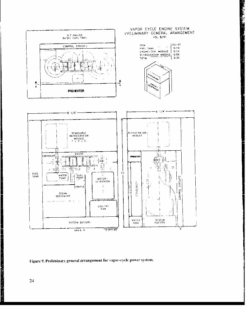
5.6 Gleneral System Arrangement
A layout of' the general arrangemient of' the preliminary power syst-'n is,sh1own inl figure1 9. It assumfes at box of 6.2'5 x 8.25 x 10 Inl. (0).3 f't3) to) coItalinall thle sy'stemi components, including an, '[.'-shaped fueI tank for 24 hoursof, operation. anid an allowance of 105 in.3 for a1 remol(v.Ible reri C-erat ionmodule. I'lc engine-generator anid vapor-cycle syStemI componentCIs arepackaged inl a volumei of 0. 14 ft3 . ObviouIsly many different arrangemients
22
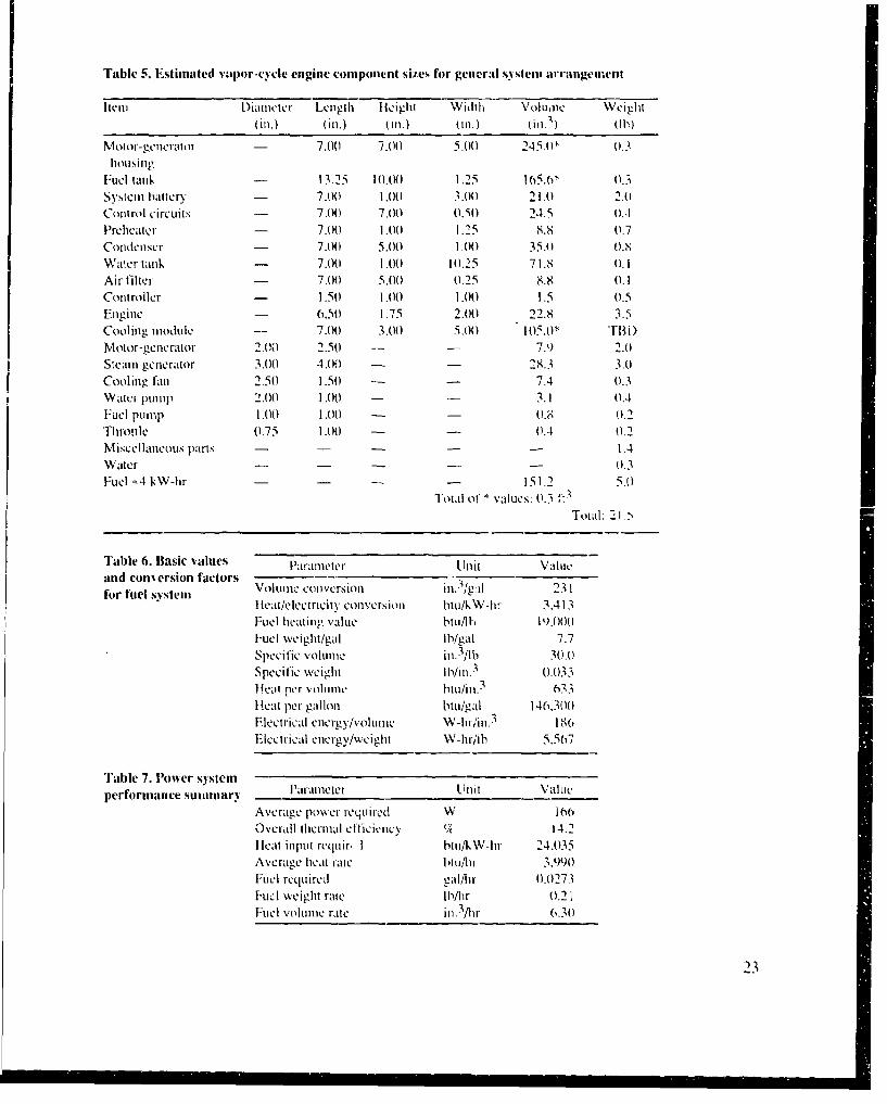
Table 5. Estimated i'apor-cycle engine compontnt sizLs for general system arrangenent
Item I Diametcr Lengih Iil ci ght Width Volu ne e illIt(ill.) (Oll.) (ill.) o ll.) (hi.1) (11))
Molor-gellnraht - 7.00 7.00 5.00 245.0* 0.3housing
Fuel tard, -- 13.25 10.(K) 1.25 165.61, 0.3System battery - 7.00 1.00 3.00 21.0 2.1)Control circuits - 7.00 7.01) 0.,5(0 24.5 A.4Preheater - 7.00 1.0(0 1.25 8.8 0.7Codienscr - 7.0)0) 5.010 I .00 35.0 0.8Water tank - 7.00 1.O0 10.25 71.8 0. 1Air filter - 7.0) 5.01 11.25 8.8 (. 1Controller - 1.51) 1.00 I .O00 1.5 (1.5Engine - 6.510 1.75 2.00 22.8 3.5Cooling module - 7.0) 3.01) 5.101) 11)5.1}* rmfI)Motor-generator 2.00) 2.50 --- 7.9 2.0Steam generator 3.0)0 4.(H) - 28.3 3.1)Cooling fan 2.51) 1.5(1 - 7.4 0.3W ater pump 2.00 1.0)) -- 3.1 11.4Fuel pump 1.001) 1.00 - - 11.8 o.2Throutle 0.75 1.00 ) - 0.4 (1.2Miscellaneous parts - - - 1.4Water -.- - 01.3Fuel .4 kW-hr - ... 151.2 5.0
"Total ot * values: 0.3 1 t aTotal: 21.>
Table 6. Basic values Parameter Unit Valueand corn ersion factorsaon elsioe Volume conversion in.3ig~il 231fIleal/electricity conversion btu/kW-hr 3.413
Fuel heating value blu/l-, 19.00))Fuel weight/gal Ib/gal 7.7Specific volunie in. 3ilb 301.0)Specific weight Ib/in. 3 01.033II cili pthr voluiinme btu/i[n.3 633He'at per gallon btu/gal 146,3001Electrical energy/volumel W-hr/in. 3 186 ,EIctlrical energy/weight W-hrlib 5.567
"Fable 7. Power systemperformance summary Ptraneter Ulit Valc
Average power required W i16Overall thetnal efficiency '4 14.2Ileat input rCquir, I btu/kW-hr 24.035Average heliat rate I1t1/h1 3,990FuCl required gal/hr 0.0273
FLuel weight rate Ib/hr 0.21Fuel Voluime rate in. 3/hr 6.31)
23
VAPOR CYCLE ENGINE SYS'IEM
Q7 CAT ~ll FPFLIMINARY GENERAL ARANGEMENT
DitSLL I U F L TAN. 1101L 8/91
CON~T
ROL CIRCUITZ ~ ANK MDL 1
---- ENGINL -GIN M UIE 0.14/ .IRIE.RICIRHA1ION MODULE 0.06
N107AL 0.30
PREIEATER
8 1/4- 6 1 /4-
REOAL RE K I AT1t.R~RIRI FRIGIITIAMODUL
MODUULE
ENGINE~F U EL
STEAT
JOO iN
FAN '1
I D
SYSTEM~~k~ NERART I AER SYTTR
Figure 9. Prlirninan genROTL arnEmnfr pr- tcpersei
ST4A
can be pursued with die goal of optimium packaging. However, more de-tailed design of the components and their interrelationships nieeds to be donebefore anl optimium packaging design effort could be fruitful.
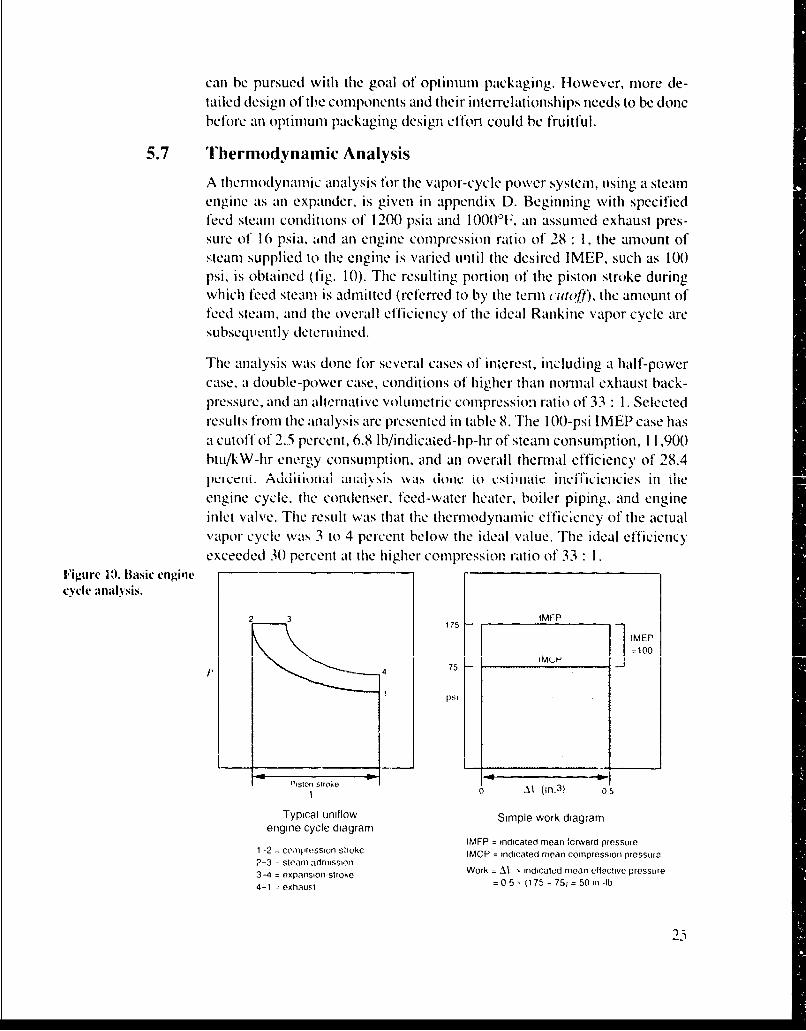
5.7 Thermodynamic Analysis
A thermodynamic analysis for tile vapor-cycle power system, using a steamnengine ats an expander, is given in appendix D. Beginning with specifiedfeed steamn conditions of' 1200) psia and 1000TF, an assumed exhaust pres-sure of' 16 psia, and an engine compression ratio of 28 :1 , the amnount ofsteam supplied to the engine is varied uqtil the dcsired IMEP, such as 100)psi, is obtained (fig. 10). The resulting portion of the piston strojke duringwhich feed steam is admitted (referred to by the termn curoft), tilc amiount offeed steami, and the overall efficiency of the ideal Rankine vapor cycle aresubsequently determined.
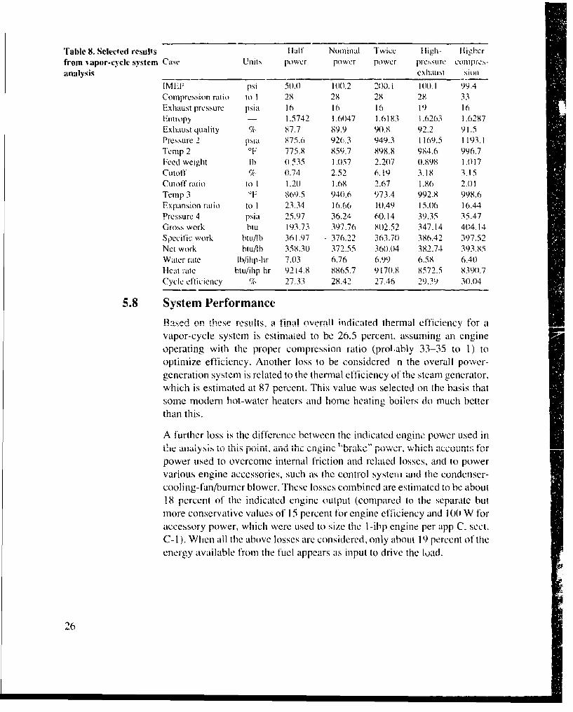
The analysis wats done for several cases of interest, including at half-powercase, at double-power case, conditions of higher than normal exhaust back-pressure, and anl alterlnative volumietric compression~ ratto ot 33 :1 . Selectedresults fromt the analysis are presented in table 8. The I 00-psi IMEP case hasat cutoff of 2.5 percent, 6.8 lb/indicaied-hip-hr of steamn consumption, 1I ,900)btti/k-W-hir energy consumption. and an overall thermal efficiency of 28.4pI)CI ceit. 'uoAdd lioid %v ~ V~ as 001 ic 1M LcSi i iiaic Iiicilicieiicies Inl tileengine cycle, thle condenser, feed-water heater, boiler piping, and engineinlet valve. The result wats that the thermodynamic efficiency of the actualvapor cycle was 3 to 4 percent below the Ideal value. Thle ideal efficiencyexceeded 30 percent at the higher compression ratio of 33 :1
Figure 19). Basic enginecycle analysis.
2 3175~- iMFP E
4 75
PS
-0 Pision stroke il A i-1 t(i 3 05
Typical unitlow Simple work diagramengine cycle diagram
IMFP = indicaied moean fcrward pressure1 -2 =cc'.iipresslon s~rOkC IMCP = indicated mean comfpressionI pressure2-3 -steam admission3-4 =expanisioni Stroke Work =Al x indicated mean effective pressure
4-1 ~exhaust = 05 , (175 -75; = 50in -ib
"rable 8. Selected results Half Nominal Twice High- Higherfrom vapor-cyelc system Case Unit1 power power power pressure comprfs-analysis exhaust sioi .
IMELP psi 50(. 100.2 200.1 )100.1 99.4Compression ratio to 1 28 28 28 28 33Exhaust pressure psia 16 16 16 19) 16Entropy - 1.5742 1.6047 1.6183 1.6263 1.6287Exhaust quality ch. 87.7 89.9 90.8 92.2 91.5Pressure 2 psla 875.6 926.3 949.3 1169.5 1193.1Tc mp 2 OF 775.8 859.7 898.8 984.6 996.7Feed weight lb 0.535 1.057 2.207 0.898 1.017Cutoff , (0.74 2.52 6.19 3.18 3.15Cutoff ratio to 1 1.20 1.68 2.67 1 .86 2.01Temp 3 0F 869.5 940.6 973.4 992.8 998.6Expansion ratio to 1 23.34 16.66 10.49 15.06 16.44Pressure 4 psia 25.97 36.24 60.14 39.35 35.47Gross work btu 193.73 397.76 802.52 347.14 404.14
Specific work btU/lb 361.97 376.22 363.70 386.42 397.52Net work btu/lb 358.3(0 372.55 360.04 382.74 393.85Water rate lb/ihp-hr 7.03 6.76 6.99 6.58 6.40hleat rate btu/ihp-hr 9214.8 8865.7 917(0.8 8572.5 8390.7Cycle efficiency % 27.33 28.42 27.46 29.39 30.04
5.8 System Performance
Rased on these resu!ts, a finAl overall indicated thermal elficiencv for a
vapor-cycle system is estimated to be 26.5 percent, assuming an engineoperating with the proper compression ratio (prolably 33-35 to 1) tooptimize efficiency. Another loss to be considered n the overall power-generation system is related to the thermal efficiency otf the steam generator,which is estimated at 87 percent. This value was selected on the basis thatsome modern hot-water heaters and home heating boiers do much betterthan this.
A further loss is the difference between the indicated engine power used in:lic aiAlysis toill, pot, a . , w .count fr
power used to overcome internal friction and related losses, and to powervarious engine accessories, such as the control system and the condenser-
cooling-fan/burner blower. These losses combined are estimated to be about18 percent of the indicated engine output (compared to the separate butmore conservative values of 15 percent for engine efficiency and 100 W foraccessory power, which were used to size the 1-1ip engine per app C, sect.C-1). When all the above losses are considered, only about 19 percent of theenergy available from the fuel appears as input to drive the load.
26

A final loss mechanism is the inefficiency in the electric generator andretrigeration system. This is estimated at 25 percent of the power input othcse elements. Thus, the overall soldier power plant thermal efficiency isestimated to be
E = 100 x 0.87 x 0.265 x 0.82 x 0.75 = 14.2%
as illustrated graphically in figure 11. This translates to a required heatingvalue input of
3413 btu/kW-hr0.142 - 24.035 btu/kW-hi0.142
of actual work delivered to the soldier. For fuel at 19,000 btui/lb and 7.7lb/gal, the fuel rate for an average power output of 166 W is 0.21 lb/hr and0.027 galihr, as summarized in table 7.
Energy available Energy Electricalto drive load: delivered to & cooling
Enerqy 18.9% load: 14.2% energy outputavailablefor work: -7_
2 % - -E"nergy loss n generator& refrigerator: 25%
Energy loss to mechanical friction, accessories: 18%Pump, pipe, & valve loss
available from Engine thermodynamicsteam: inefficiency87%
Energy availablofrom fuel
-5550 W-hr/lb'=180 W-hr/in. 3
1 80% Energy loss invapor-cycle
system: Energy lo.s fromS.i."/o vapor-cycle system
(ideal thermodynamics)
SEnery loss .ne
steam generator: 13%
Fig.ure I L. Energy stream for vapor,cycle powered system.
2-/
6. Liquid-Cycle Engine Technology
6.1 Summary of Available Information
The status and viability of liquid-cycle engine technology is undeterminedat the present time. The limited scope of this study did not permit extensiveliterature review or design analysis. A report by the Cleveland PneumaticTool Co. 1211 (and associated patent 11 01) is the maijor itemn obtained, and itis not available in the public literature. However, the principle of a liquid-cycle engine may lbe useful in future research efforts, so the informationfrom Cleveland Pneumatic 1211j is presentedi here to stimulate analysis andfurther evaluation of the concept. Two other liquid-cycle engine patents byWesteoli 122,23] relate to this technology, as well as two patents by Malone124,251 and at recent extension of the Malone concept by White et al [261.
The Cleveland Pneumatic report 1211], written in 1960, was a "preliminary"report/proposal 1271. It contains only at few short paragraphs and someillustrations. The relevant passages of this report are its follows:
CICVChmld PneuIMaiUc has been1 actively engaged in the design and nianufacture ofliqjuid springs over a period of the laist tenl years. These springs work onl thecomprecssibility of liquids ait pressures up to 50,000 psi. They tire c:urrently used onthe iS AF F- 1 0,1 in the landing gear shock absorption system and the Polaris shockm 1t igatio sy 5'stemii.
The developmlent Wor-k on1 liquid springs led to the study of the possible use of fihecomipressibiitby and thenna11tl expansionl of JUliqiS to convert he~at to work. A I iqUidhermiat eng inc has the potenut iat otdeli yernVn large hiorsepoiwer trout a relatively
smiall eniginte. It has., the catpability ot extracting he at energoy anld Converting it touseftut work wheni ret at i ye iy ow temuperaut re di t~e rent ial s exist.
Over the past two and a hafyears. feasi hiIi ty StUdies, h ave bcen c'.m pIeted midyenlied by D)i. R. F. B oti. head of the LDepa it iictitt ot Mcedtan ical Engi necering atiCaISe l1istit te of' Technology. Dr. Boll's anailysis Of onle MIC thi oposed flu idicycles. Whieh wa1s comlpleted two y'ears, ago. is meTIdedI a1'. an1 a1ppen1dix (If thisreport. The engine pert -mariec indicated by Dr. 13otN Ms SI alsiMshs been Co1sid -e rabl y im proved by deve lopit ent work over thte pa: A two years.
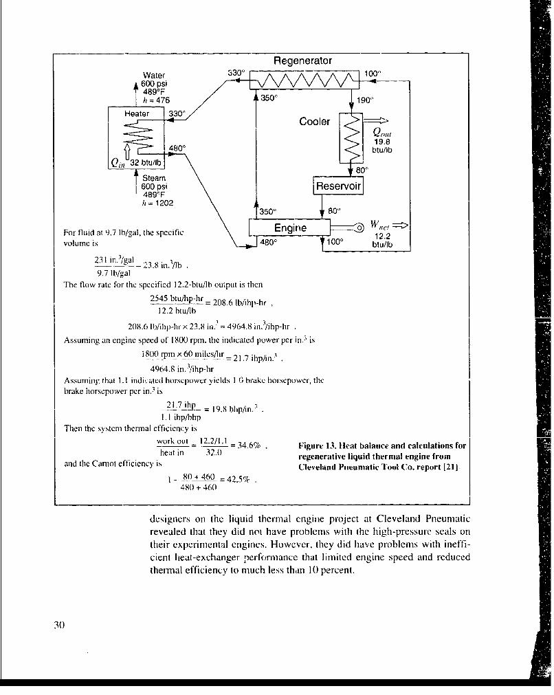
Figure 12 is ai composite of two figures taken front the report 1211J. It showsat test setup for compressing, heating, expanding, and measuring the tem]-peratture and Volume of' it fluid, and the resulting pressure-volume diagramlfrom ia test conducted onl "Cel lUlube 150 fO'luid. Figure 13 is at "heatbal ante'' diagram for at liquid thermal regenerative thermodytnamie eyce Ifromn ;he report 12 11, and some simple calculations for efficiency (34.6perk ent) and specif ic engine size ( 19.8 hp/in. 3 ) cont~iel'sed flrotu th-ose in the
28 report.

Test setup P-V diagramfor P-V diagram for Cellulube 150
, _ _4-15-60
_ _ I 90'F 350°F21.6 23.3
20.000-lb2load
1,0
____ ____ ___ ____ Ii 15,000
0 1Net work
5=
.3580 ft-lb
75T
2'75F
0 22.9
21 22 23 24 25 26Volume (in. 3)
Figure 12. Illustrations fromn Cleveland Pneumatic I ool Co. paper 1211 on liquid thermal engine.
The values in figure 13 appear to be speculation on the part of the author ofthe Cleveland Pneumatic report 1211. The efficiency is about twice as high
as the values derived by Bolz, whose analysis is reproduced in appendix B(sect. B-3). Also, the value of the heat input, Qj, (32 btuNOb), when divided
by the 150'F temperature differential shown for the heater, results in aspecific heat value for the fluid that is about half as large as expected for a
petroleum-based tluid. This small specific heat, when used in the simpleanalysis of figure 13, would yield an efficiency about twice as large, and anengine size about half as small, as would an expected value of specific heat.Furthermore, the indicated efficiency of 12.2/32 = 38.1 percent seems tooClose to tllt" "" -a," I ... .C": -: ........ - ..A.'. C -....r. fo t. .. .... :
temperature difference (480 - 80 = 400'F) to be realistic.
Bolz's analysis (app B-3) refers to "a separate enclosure" and "the original/referenced report" in support of part of his analysis. These items were notavailable. He also uses values for the properties of acetone taken from anarticle by P. W. Bridgeman 128]. Six graphs of these acetone data areincluded with the report 121 ], but they are not reproduced here.
Representatives from Western Gear Corporation, a contractor for the Army'sTransportation Research Command in 1960-61, visited Cleveland Pneu-matic Tool Company at that time and observed an experimental liquid-cycleengine in operation. A recent conversation 1271 with one of the mechanical
29
Regenerator
Fo fudt. Wl/ alther specific00
volum i= 48300 100 900/l
9.7 lb/ga
2 45 0 btih-h -20.6lbih-h
12. bt/ b tu/0
Assumin anegiespedoi80rm h niae oe e n iesero
180 rp 12 602 mlsh 17ipi
496.8fi. ),ip-h
Aslumeins that0 10.0 bdtue hr/oeryed I.brkehreowr h
brak horsepowe pe i.,i= 2'. 7 i hp - 9./blpmn
9..7 ihplhpThen thew systemfo thermaleffiied~ is2bu~ upt ste
hsuiga egn p ed t of10 in , 320 idctdpw rper gen eraiv liudteml nief
i 80+4rp x60 -42es/r%
Asureveal1.1ini, ed thatpe thydieds n.0 hrave hosproblertnwtheihprsuesaso
cient heat-echange peperac that liutdegiesedanseue
Tethsytm thermal efficiency ' timcses n10pret
30k o t -1 ./ . 46 i u e13 e tb l n ea d c l uai n o
6.2 Engine Description
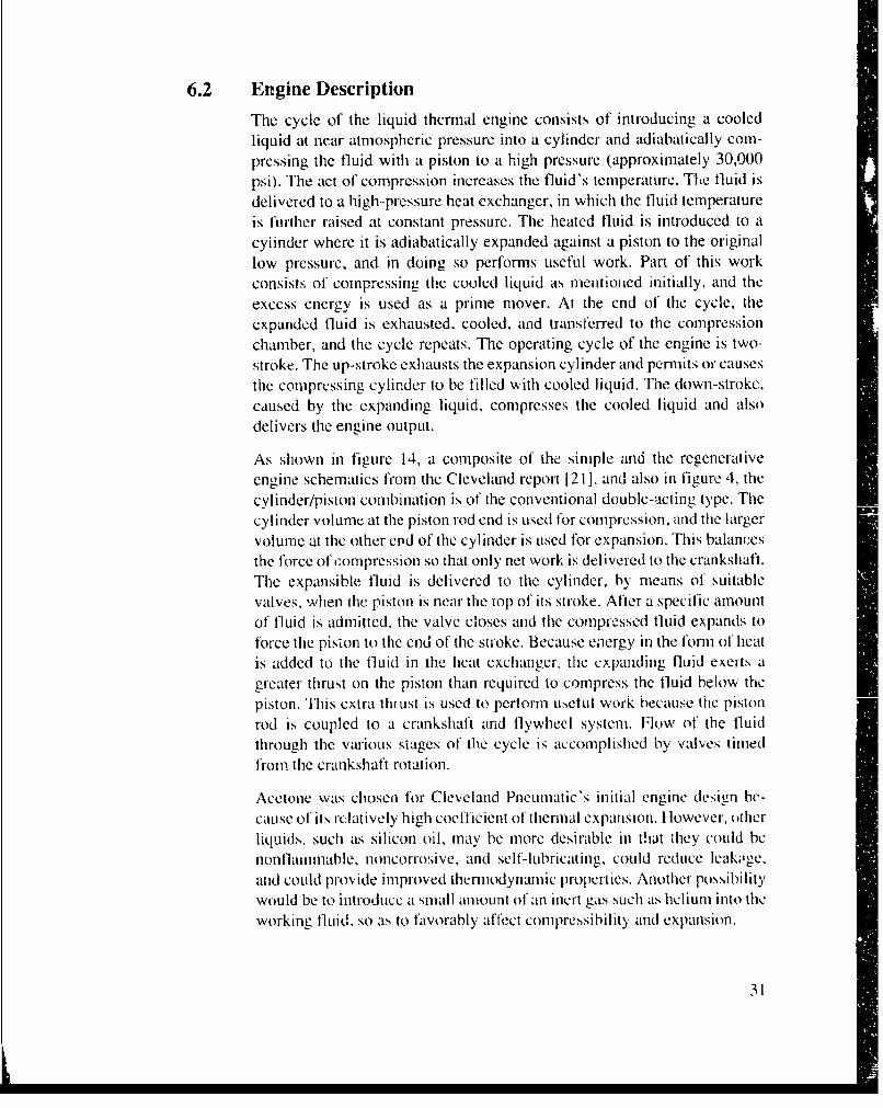
The cycle of the liquid thermal engine consists of introducing a cooledliquid at near atmospheric pressure into a cylinder and adiabatically com-pressing the fluid with a piston to a high pressure (approximately 30,000psi). The act of compression increases the fluid's temperature. The fluid is
delivered to a high--pressure heat exchangcr, in which the fluid temperatureis further raised at constant pressure. The heated fluid is introduced to acylinder where it is adiabatically expanded against a piston to the originallow pressure, and in doing so performs useful work. Part of this workconsists of compressing the cooled liquid as mentioned initially, and theexcess energy is used as a prime mover. At the end of the cycle, theexpanded fluid is exhausted. cooled, and transferred to the compressionchamber, and the cycle repeats. The operating cycle of the engine is two-stroke. The up-stroke exhausts the expansion cylinder and permits or causesthe compressing cylinder to be filled with cooled liquid. The down-stroke,caused by the expanding liquid, compresses the cooled liquid and alsodelivers the engine output.
As shown in figure 14, a composite of the simple and the regenerativeengine schematics from the Cleveland report 121], and also in figure 4, the
cylinder/piston combination is of the conventional double-acting type. Thecylinder volume at the piston rod end is used for compression, and the largervolume at the other end of the cylinder is used for expansion. This balancesthe force of compression so that only net work is delivered to the crankshaft.The expansible fluid is delivered to the cylinder, by means of suitablevalves, when the piston is near the top of its stroke. After a specific amountof fluid is admitted. the valve closes and the compressed fluid expands to
force the pision to the end of the stroke. Because energy in the forn of heatis added to the fluid in the heat exchanger, the expanding fluid exerts agreater thrust on the piston than required to compress the fluid below the
piston. This extra thi ust is used to pertorm usCulI work because the pistonrod is coupled to a crankshaft and flywheel system. Flow of the fluidthrough the various stages of the cycle is accomplished by valves timedfrom the crankshaft rotation.
Acetone was chosen for Cleveland Pneumatic's initial engine design be-cause of its relatively high coefficient of thermal expansion. I lowever, otherliquids, such as silicon oil, may be more desirable in that they could benonflainimable, noncorrosive, and self- lIbricating, could reduce ieak•,gc,amid could provide improved themmodynam ic properties. Another possibilityWould be to introduce a small amount of an inert gas such as hclium into theworking fluid, so as to favorably affect compressibility and expansion.
31

Figure 14. Schematics ofliquid thermal externalcombustion engine [21].
-High-pressurecircuit
Rflservoir
Low-pressure circuit
* Relat vely ..ficienF Heat exchanger
ll High-pressure d to the high mean-effective pressure
•• P-"'atD~sHpacmentexchanger
6 Siplntaresig and eradntn age
Advantages of a liquid-cyc3e 2hcinodyuaiii powei ,ystc- Could be asfollows:
"• Relatively low working temperatures, of about 400 to S,00°F
"• Relatively efficient heat exchange due to liquid-to-metal interfaces
"• Quiet operation, owing to steady-state condition of the working fluid
"• Small engine size due to the high mean effective pressure
"• Relatively slow speed operation, of about 1000 to 3000 rprn
"• Simple starting and operation
32

Disadvantages of the liquid-cycle system would be expected to relate to thefollowing:
Efficiency may be low because of the low peak-temperature level, althoughthe extreme pressure conditions nay offset this effect to some extent.
" High operating pressure will require special sealing techniques and possiblyre-;ult in high seal friction forces.
" At least one high-pressure heat exchanger will be required, and this will addweight to the power system.
" Throttling of fiuid through high-pressure valves may result in high energylosses and unacceptable wear of seating surfaces.
Relatively low coefficients of expansion and small compressibility of thefluid could result in some critical relationships between respective volumeswithin the engine and heat exchanger elements, an may require rather closecontrol over some of the temperature conditions.
33
7. Liquid-Cycle Engine Approach for Individual SoldierRequirement
Tile liquid-cycle external combustion system is similar to the vapor-cyclesystem in terms of engine sizing, types of components, etc. Assuming thelower limit of Bolz's analysis value of about 10 hp/in.3 at an engine speed of1000 rpm, an engine of I lip (indicated) would have a cylinder volumne ofonly 0.1 in. 3 at this speed. A more realistic speed for an engine of this sizewould be 3000 qrfi. The result is a displacement of 0.033 in. 3, whi,'htranslates to a bore and stroke for a single cylinder of about 0.25 in. diameterby 0.67 in. long.
Although heavy-walled structures are needed to contain the very highpressures involved, the small scale of the components is an advantage, illthat small size results in higher strength-to-weight ratios. Thus, tile weightpenalty normally associated with high-pressure systems may nlot be assignificant for a system sized to produce a net output of only 0.5 hp.
The general arrangement for a liquid-cycle power plant would probably besimilar to that for the vapor-cycle plant shown in figure 9. The names of the
components would be modified appropriately, the engine configurationwould change to be similar to that shown in figure 4, and a regenerative heatexchanger might be added. The heat source would probably need to bedesigned to achieve close control over the fluid temperature, and a hydraulicaccumulator may need to be added. A modern synthetic fluid, perhaps withsome entrained gas, would probably be used as tile working substance. Theoverall weight of the power system is expected to be close to that of acomparable vapor-cycle system, whereas the size of the system might besmaller.
Designing a liquid-cycle engine and power system i. expected to require.;m.... mant .ng.. ,,'," There i- relativelxy liteIh- standrd pra.'ice on which to. .,..., • , , hP., ,,a• .... .... o il .. . . . .. . .. .
base the design. However, there is a good body of literature on high-pressure technology (see Tsiklis 1291. for example), and much progress hasbeen made in the last two decades in high-pressure water-jet cutting technol-ogy 1301, where the pressures used are similarly high. The Iask should beginwith a study to select and characteriZe the bcst fluid or fluid system to use inthe design. ]'his should be followed by a rigorous analysis of the engine andthe" entirc liquid thermiodynamic cycle, including realistic energy-loss niecha-linisms for each of tile components. If the concept survives to this point, thendetailed design of a research engine should be done, follow, ed by construc-tion and testing of an expcerilental mmodel.
3-1
8. Conclusions
Table 9 is a preliminary comparison of the vapor-cycle system with pre-sumed Stirling and internal combustion power systems for the individualsoldier. It shows that the vapor-cycle system is essentially competitive withthese alternative technologies, and it could be a beiter choice depending onthe specific mission. At the current stage of dcvclopment of these concepts,comparative estimates have so much probability of error that such detailedconclusions are unwarranted, other than to point out that additional researchneeds to be done oni all three candidates.
The vapor- and liquid-cycle engine technologies potentially offer a distinctcombination of advantages for soldier system power. These arc quiet andefficien, operation, diesel fuel compatibility, compact size, a broad powerrange, and long-duration mission capability. However, these advantagesprobably come at a slight penalty in cosi and weight compared to an internalcombustion engine sy,;tem. Another consideration is the fact that thesetechnologies have to be developed much further than does the internalcombustion technology, which already has a partially established industrialbase.
The vapor-cycle engine technology is especially viable and of reasonablylow dcvchopmenfi risk. Seiection of the proper baseline design and theapplication of modern component technology is expected to eliminate anypioblems or disadvantages residual in the prior art. Liquid-cycle enginetechnology is not nearly as advanced as vapor-cycle engine technology, so alarger investment in research will be required for its potential to be fullyexplored.
35
LM
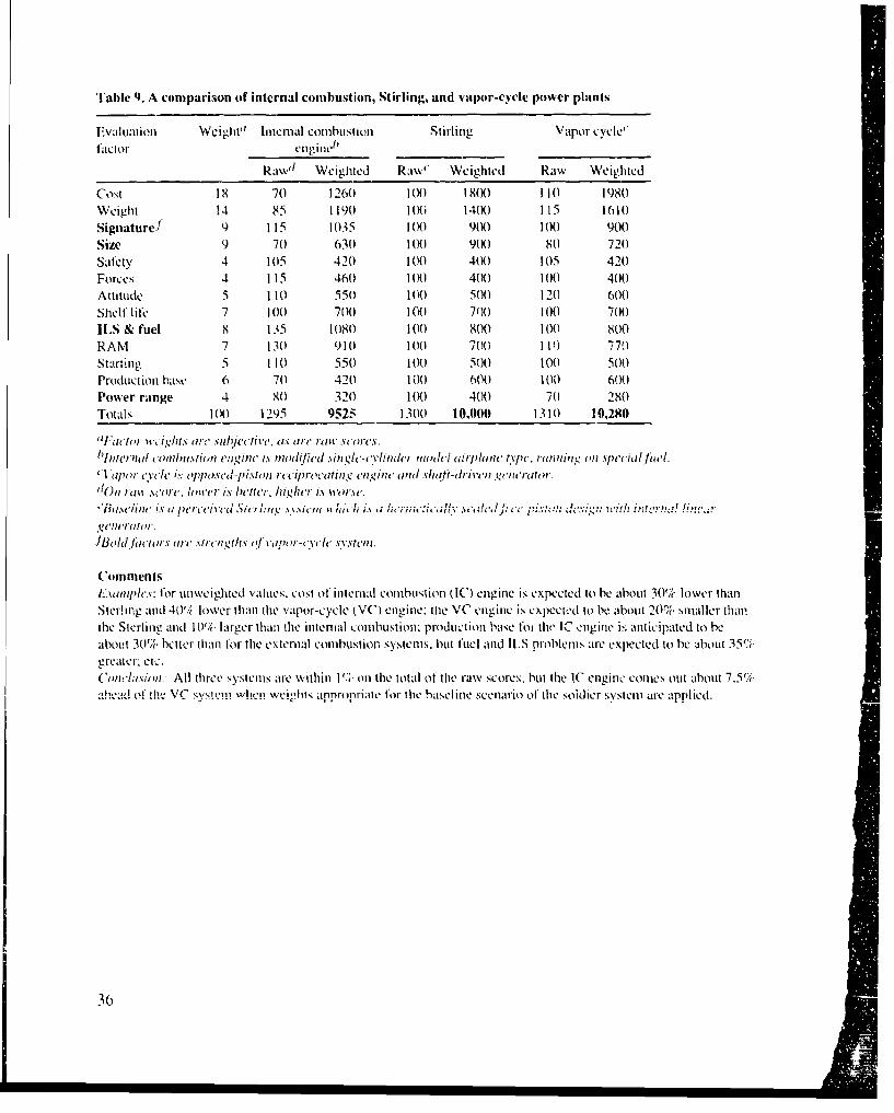
Table 9. A comparison of internal combustion, Stirling, and vapor-cycle power plants
FValtILatiOll Weight llnternal combustion Stirling Vapor cycle'1'aclor ilngine_
Raw'1 Weighted Raww" Weighted Raw Weighted
Cost 19 70 1260 100 1800 110 1980Weight 14 85 1190 100 1400 115 1610Signature] 9 115 1035 1 W0 9(X) 11W 900Size 9 70 630 1 (K) 90W 80 720Salety 4 105 420 1 0X) 4W 105 420Forces 4 115 460 10(X) 401 100 400Auitude 5 110 5501 1 (K) 500 120 600Shelf life 7 100 700 100 700 100 700ILS & fuel 8 135 1080 100 800 100 800RAM 7 130 910 100 700 11:) 779Starting 5 11(0 550 1(.) 500 1 (1) 500Production base 6 70 42(1 11(1 6W1) 100 600Power range 4 8( 321 1 (K) 400 70 280Totals 100 1295 9525 1300 10,0((0 131(1 10,280
all-actor VI-tight.s are sub~jec'tivc, as• are ralt. sceres.
hln1reriall cto'lIti(,1t'a1 engim' is modijic'l Niligh'-cli-fnder mpocl i crpl/nh typtc. runllnin on special fi'l.•I apor cycle is% oplposed-lpistont I ciprocatitng ('1/,gint,< and .\hilf-dri'vell g(IIITurtor.
110n ra' ,sor,. lower is bettcr. hither is worse."BtSlm i'mi is t pj rcct' i c' , ,i cl c lit, " .N . ' .rhit h i.N d' .;7. . . :ica w I t e ,di -,! 11- **'**. ro'." d * ' .......... 1.... . ........
(ommenlsl-siplcs: for unweighted values, cost of internal combustion (IC) engine is expected to be about 30% lower thanSterling and 40'/( lower than the vapor-cycle (VC) engine: tile VC engine is expected to be about 20% smaller thantlhe Sterling and 10% larger than the intenial combustion; production base foi the IC engine ik: anticipated to beabout 301% belter than for the extental combustion systems. but fuel and ILS problems are expected to be about 35%greater; etc.(oncltusion: All three systems are within 1% on the total of the raw scores, but the tC engine comes out about 7.5%
.Yc w&,h"i%',:tnronaoriwithe baeln sciari arlle applied.hnfh, y r the basline scenario of the soldier systen atc
36
9. Recommendations
Because the Army is faced with a need that is new and especially difficult tomeet in a specialized military field, it seems appropriate to reconsider thespecial advantages of external comnbustion technology with an open mind.The particular advantages of multifuel capability and quiet operation areattractive enough in view of the individual soldier application that the Armyshould iocus some research effort on seriously exploring it', potential. It isrecommended that the Army explore both vapor- and liquid-cycle technolo-gies, by analysis and laboratory experiment, to the extent necessary tovalidate their capabilities and to establish their viability for applications thatmay requite their unique combination of characteristics.
The following topics are recommended for university research projects toexplore and advance the technology of high-performance vapor- and liquid-cycle external combustion engine power systems for individual soldierapplications of the future. Each of the topics is visualized as a modular taskat the level of effort of a graduate student thesis.
" Refine a mathematical model of a high-performance unillow steam engine,including detailed energy-loss mechanisms, and determine the best designcharacteristics for the target application. (See recommendations in app D.)
" Refine a mathematical model of a liquid-cycle engine, including a study ofoptimum working fluids, and determine the best design characteristics forthe target system.
" Design a miniature once-through "boiler" for heating thý working substanceat optimum efficiency and power density.
0 Investigate miniature high-performance burner technology and design anOi'11t1-11Util i bl[ltei SyC'iil 101 use WIL il tHitiiatuifc 1 - po Wt' sysicin ulniCf.
" Based on the most advanced heat-transfer component technology, designminiature high-performance air-cooled heat exchangers/condensers tailoredfor application to vapor- and liquid-cycle power systems.
" Analyze the performance of Rankine vapor-and liqL;ud-cycle power systemsbased on the detailed design analysis (lone for their expander, heat-ex-changer. boilIcrburner, piping, valving, pumping. and insulation compo-nents.
"" Design an o1ptimi]Zed control system for fully automatic and safe operationof at miniature vapor-cycle power plant.
37
"* Investigate optlnimu mlat rials (mletals. cerannics., therm11al in1sulaion00, Ilubi-1cants) and seal technology for appl ication to durable. high-pressure, high-temperature, steam - and liquid -cycle power system ~ompilonents.
"* Investigate diesign ConfIi gurations for thle most practical iriethiod of' achtievingclosed-cycle operation (withi no loss of working hluid) anld any-ati itudcoperation ol vapor- and liquid-cycle power plants.
"* Demionstrate miniature steam engine technlology by' designing. bit ld ing.0and testing an experimental enlgine of I to 2 indicated-hp1 capacity, includingappropriate steam generator, condenser. ecI. co1ponlenlts. that would besuitable to power a miodel airplane. (This topic would requite a1 level Ofeffort equivalent to three or fouir of the other tasks.)
"* Demonstrate miniature h q~iid-cycle engine technology by designi iig, build-ing. and testing a laboratory experimental engine of I to 2 indicated-hipcapacity. (This topic would require a level of ef'fort equivalent to three orfour of the other tasks.)
38

References
1. M, 1iggins. F. 1lamlin, W. Klein, and J. Sites. An Analvsis o.Filture USArm\" T j('tial iEc•'('ic Powver Requirements. B1)M Corp.. BI)M/N4CI-86-(J949-TR, for U.S. Armliy BRDLC-STRB1'F,-F (March 1987).
2. G. Levine. The Car Solution: hic Steam L-htgine Conm'i o. A-,,c. tlorizo--Press (1974), ISIIN-0-8180-1707-4.
3. C. Camp. Senate to Stud Iv Steam Cars as a Solution /fin Air Pollution:Detroit Liket. Stattts Quo. 'hc Wall Sireet Journal (27 May 1968), p 34.
4. A. NI. Marks. heat •lectrical Power Tranisducer. U.S. Patent 3,.297,887 (10January 1967).
5. R. Salzbrenner, Shape MemorY Heat 1ea ngni. , J. Mater. Sci. 19 (1984).1827-1835.
6. D. J. Bak, Metal's MAemor\ Powers "Practical" H!et E-ngine, 1)esign News(2 D)ecember 1985), 98-99.
7. F. E. Wang. The Thermohih' Nitinol langin'. Soc. Automotive E1-0. Paper .851495 (September 1985).
8. M. Nishikawa. M. Kodera, 1. Okata, K. Yamanchi, and K. Wutaiiakb, hi'gc
Scale Tilt Platt heat Engine Using SMA. Proc. International Conference onMa'tensitic Transformations. Japan Institute of Metals (1986), pp 1041-1046.
9. P. F. Massier. C. P. Bankston, G. Fabris, and L. D. Kirol, lDirect tne.'1r1yComversion To' ibol,.•, P'rogress Report for the lner~y Conversion and
Utilization Technologies Program (I5 Jtnc 1988). pp "6-48.
10. W. B. Woslcott. Jr., Liquid Cycle iHeat Engine. U.S. Patent No. 2.963,853(30) December 1960).
II. L,. L. Johnson, The tlvdrauuli Spring. Machine Design Magazine (26 MaN1960). 114-117.
12. W. Barnard. F. 131llnwood, aid C. ItirshfCld, theat-Power Lmut,''c'rin,'.
Parts% /. !!. & 1/1, John Wiley & Sons. third edition t 1926).
13, W. J. Bessler and J. L. Boyen, D)esigpn Stu1y .'fa Steam Power *Svste•ii " (aLanding Craft, uLnder contract No. 2159(00) for the Office of Naval Re-search, Amphibious Branch (30 September 1957)
14. 0. Hlartman, Scimidt Steam l,1 ,im' More l/ifiiewt Thant l.arge.t l'rbine,
Power Magazine (7 February 1922).
39
15. E. Allcut, FThe U'niflow Steam Engine, Trans. Eng. Inst. Can. (1928).
16. R. Ayres and R. McKenna, Alternatives to the Internal Combustion Engine,Johns Hopkins University Press, Baltimore (1972), ISBN-0-8018-1369-7.
17. C. C. Williams, Steam Engine, U.S. Patents 2,402,699 (25 June 1946) and2,943,608 (5 July 1960).
18. Steaming Along on Steam, Life Magaziae (1968), 71.
19. C. Wise. Steam is Back, Machine Design iMagazine (29 August 1968), 20-26.
20. Graphite Piston, Popu!ar Science Magazine (January 1992), 42.
21. Liquid Thermal Engine, Internal Report No. 1258 of the Cleveland Pneu-matic Tool Co., Cleveland, OH ( 11 May 1960).
22. W. B. Westcott, Jr., Liquid Thermal Engine, U.S. Patent No. 3,055,170 (25September 1962).
23. W. B. Westcott, Jr., Liquid Cycle Refrigeration, U.S. Patent No. 3,079,-764(5 March 1963).
24. J.F.J. Malone, Heat Engine, U..S. Patent No. 1,487,064 (18 March 1924).
25. J.F..I. Malone, Heat Engine Operated hb' the Expansion of Liquids, U.S.Patent No. 1,717,161 (11 June 1929).
26. D. White, D. Craig. J. Duke, and D. Laurie, Apparatus and Method.1forConverting Thermal Enei-gy to Mechanical Energy, U.S. Patent No. 4,637,?11(20 January 1987).
27. Personal communication with Louis Hrush of Cleveland Pneumatic ToolCo., (216) 341-1-100, x4241, designer of experimental liquid-cycle engine\16 Dccc1be: 1991 ).
28. P. W. Bridgeman, Th7cniodvnamtic Properties Of 7 i.velve Liquid.s Between20' and 80' and up to 12,000 KGMisq-cm, Proc. Airier. Acad. 49 (1913). 1 -114.
29. D. Tsiklis, Handbook offTechnique. in Htigh-Pressure Researc h and Engi-necring, translated from Russian, Plenum Press, NY (1968): LCCCN 68-14854.
30. F. Yeaple, Diamondt, to WaFeruits--"St er-Pre'sure' Flud Powei, De-sign News Magazine (23 July 1990), 59--64
40

Appendix A. Evaluation Factors for Individual PowerSystems*
*The material in this appendix has been adapted room a s imiar documen, prepared by the Belvoir Research,
Dkevelopment, and Engineering Center (BRDEC).
41
ContentsPage
A-I. Introduction ............................................................................................ ......................... 43A-2. Cost ........................................................................................................... ..................... 44A-3. W eight ............................................................................................................................... 44A-4. Signature ............................................................................................................................ 44A-5. Safety ................................................................................................................................. 45A-6. Vibradion/Gyroscopic Forces ....................................................................................... 45A-7. Attitude .............................................................................................................................. 46A-8. Shelf iife ........................................................................................................................... 46A-9. Integrated Logistic Support (ILS) ................................................................................ 46
A-10. Reliability/Availability/M aintainability ........................................................................ 46A-Il. Size ................................................................................................................................... 47A-12. Starting/Restarting ..................................................................................................... 47A-13. Efficiency ......................................................................................................................... 47
42
A-I. Introduction
The selection of potential technologies for use in individual power systemsfor the future soldier must take into account all the various factors that havebeen used to evaluate military power systems over the past several decades.Though the factors used here are generally the same as those used previously,their relative importance is tied to the individual soldier application. Themilitary application and the fact that the system will be worn or carried by theindividual soldier makes these power supplies considerably different fromthose used for most commercial purposes. The following factors are consid-ered to be important for the early stage of development:
CostWeightSignatureSafetyVibration/gyroscopic forces
Attitude effectsShelf fiferitegrated logistic support (ILS)
Reliability/availability/rnaintainabiliiySize iStarting/restartingEfficiency
These factors are not truly independent, since there is a large degree of'interaction among them. They are meant to guide the selection of designs andtechnologies away from those that are obviously not appropriate for theindividual soldier application. They should not be considered to preclude theinvestigation of promising power systems, just because some of the require-ments cannot be met today. However, when a particular power approach isdeficient, any effort to correct the dc,...ic.icy should be . isi.e. • d fromir theaspect of cost and realism. •
Before discussing each of the factors, it is helpful to discuss the militaryenvironment to help point out the extreme difficulty of meeting all thepossible requirements. The military environment is taken to mean anyenvironment where the soldier will use the power system. It covers thetemperature extremes found worldwide and altitudes from below sea level tothousands of feet above sea level. One consideration is that the density of air(and the oxygen content) can vary by a factor of two from sea level and -65°F,to 8000 ft and 95°F. Other military environment concerns afe in the areas ofblowing dust/sand, salt fog/spray, and chernical/hiological agents. These
43
environmental conditions must be considered when applying several of theevaluation factors to various power supply candidates.
A-2. Cost
The cost factor is perhaps the least definable yet most important factor in thelong term. Although high cost may be acceptable when enhanced perfor-mance is attained, the expected decline in future Army budgets makes cost aprime consideration. Life-cycle cost is related to many of the other factorsdelineated below. Considering the technological barriers, it may be a matterof whether it can be done, rather than how much it will cost. If a particulartechnology has prohibitive costs at this time, a manufacturing methods andtechnologies program could be instituted. If material costs are prohibitive,research programs aimed at specific items will be needed. The cost will beconsiderably affected by the quantities, which cannot be known at this time.
A-3. WeightThe weight of the power system must be minimized. The weight of all thevarious pieces of equipment that the soldier must carry on the battlefield isalready a substantial burden. The addition of various new pieces of equipmentwill not relieve the need for much of the current inventory, particularly in thenon-power-ronsuinin__ -irea. The weight factor is influenced by powerrequirements (peak, continuous, and average) and by the time betweenresupply/refueling. Weight should be considered from the perspective of totalmission weight, which includes unit weight, the weight of fuel, and the weightof any other expendables required for missions of various lengths.
A-4. Signature
Several categories of signatures may be affected by a power source and needto be evaluated.
Noise signature. The noise generated by the power source can be fuiihe'ibroken out into noise that is a health hazard, noise that will interfere withcommunications, an(d noise that will render the soldier detectable by enemyforces. General policy states that personnel should be provided an acou,;ticenvironment that will not cause personnel injury, cause fatigue, or in any otherway degrade overall effectiveness. The first two categories of noise arecovered by various human-engineering documents. The third category,detectability, is more difficult to specify, since it depends on environmentalconditions, frequency spectrum, and the capabilities of the opposing forces.The future threat may be equipped with amplified, frequency-selectiveenhanced-hearing devices, so the power system noise should not contain
44
bands or characteristics that are significantly different from the naturalbackground.
~Ehtrwagnetiw signature. This category involves the same three issues asthe noise discussed above. A health hazard associated with the power sourceis not considered to be probable but does need to be considered. Electromag-netic signals can interfere with communications signals either sent or re-ceived by the soldier. The solCder will also be vulnerable to detection ifelectromnagnetic emissions are present.
inf[rared signature. One of the most difficult signatures to suppress for apower source is its infrared (IR) signature. No power source is 100-percentefficient, so that some waste heat is given off. Present IR detection devices aresophisticated enough to detect, at close range, small objects that are only a fewdegrees above or below ambient conditions. Future opposing forces couldhave quite formidable IR detection capabilities, so the power system will needa high degree of suppression in this area. Generally the IR signature shouldbe patterned to simulate background environmental conditions.
Visual siniature. Detection by visual means is a threat that is continual andrequires no special equipment, although the enemy may use vision enhance-ment to aid detection some of the time. This threat can be defeated by typicalcamouflage methods, however, designs should avoid obvious shortfalls suchas shiny surfaces or sharply contrasted packaging.
A-5. Safety
The safety and wellbeing of the individual soldier is one of the primary
driving forces of tile soldier modernization programl. Providing a powersource that is inherently dangerous to the soldier cannot be justified. Thesoldier will need to be protected from any detrimental effects of the powersource, such as high temperatures, toxic exhausts, dangerous chemicals/fuels,
electric shock, or fragmentation/explosion ol the system o- it:, components.
A-6. Vibration!Gyroscopic Forces
The power source may produce vibration or gyroscopic forces that affect thesoldier. MIL-STD- 1472 does not specifically cover the vibrations caused bysuch equipment, but it does recognize that vibrations may iinpair humanperformance and could decrease effectiveness. Gyroscopic forces should belimited so that the soldier retains full freedomn of movemlent without exertingadditional effort.
45
A-7. Attitude
The soldier may have to run, dodge, jump, crawl, and do other motions thatwill drastically change the attitude of the power source and/or its fuel supply.The adverse effects of changes in attitude must be considered in designing thepower system.
A-8. Shelf Life
The units must be storable in a nonoperating mode when not required. Anyspecial equipment or facilities needed for storage should also be considered.
A-9. Integrated Logistic Support (ILS)
The current trend to reduce the number of personnel in th'e armed forces willrequire each soldier to have greater capabilities and be more effective. Sincesupport personnel make up most of the force, the power system will have torequire minimum support. In other words, it would be foolish to provide atenfold increase in the capabilities of the soldier, if it meant an associatedtenfold increase in required support personnel. Consideration must be givento the requirements for training, spare parts, manuals, special tools, and theother elements of ILS. A key factor in the ILS area will be the fuel used; theuse of any special fuel should be coordinated within the logistic supply,, munt ......... .........rl,, . p .bl' ., t .od p .o with a technical ;solutionthat will not be logistically supportable.
A-10. Reliability/Availability/Maintainability
The power source must be reliable, easily maintained, and available whenrequired. The!;e factors are interrelated and are also closely tied to the ILSaspects of the system. For high reliability, the system should be simple,rugged, and capable of operation in all environmental conditions. Simplicityof design and operation will also improve maintainability. It would bedesirable to incorporate maintenance procedures in the soldier's personalcomputer, but since the unit will not be operable during most maintenance,this may be impractical. On extended missions, parts such as filters may needto be cleaned in place, or spares may net'd to be carried to support missionsbetween resupply periods. There are no current required values for thenecessary reliability and availability. However, similar systems in commandarnd control technology have extremely high values for operational availabil-ity that are geneially met through redundancy. The aspects of environmentdiscussed carlicr will have a large impact on this factor.
46

A-il. Size
The sizc of the unit, which is closely tied to its weight, risks inhibiting thesoldier during the performance of his tasks or increasing his target size.Another consideration is the carrying requirement. The system should bedesigned to provide maximum ease of handling and should provide a packagethat distributes the weight so that the center of gravity is near thc spinal axis.
A-12. Starting/Restarting
The method and time required to start and restart the system is an importantconsideration. The method should be simple and quick. The user will need todetermine if startup time is critical, since some systems will take more timeto be brought up to the operating temperature needed to support the full load.The effect of numerous start/stop cycles should also be considered.
A-13. Efficiency
Efficiency is closely tied to weight, since a less efficient system will requiremore fuel (weight) for a given mission. This relationship is not necessarilylinear, since the type of fuel used may be different. A high-efficiency systemcould require more pounds of fuel if the fuel is low in energy density.
47

Appendix B. Excerpts from Literature onEarlier Technology
49

ContentsPage
B-1. Uniflow Steam Engine ......................................................................... 51B-2. Williams Stearn Engine ..................................................................... ... 53B--3. Bolzs Analysis of Liquid The al Engine Performance................................................ 54
50

B-1. Uniflow Steam Engine
The following extract is reproduced from W. Barnard, F. Ellenwood, and C.11 irshtfeld, Heat Powver Engineerintg. John Wiley & Sons, third edit ion (1926),part 1, pp 399--390.
2.3.2. Ilnitloiw% Engine. (a) This type of engine was invenlited12il1885 by T. J. Todd of England but remained undeveloped until 1908when Professor Stunmpt', of' Charlottenburft University. succeeded inmiaking it a highly perleýcted primie mlover., S inlce that t imle othecrs halvemodified it to suit special conditions so that it is now widely used 1-0 a1variety of purposes.
(b) The unusnal /Pau,'enu of the engine may be noticed by referringto Fig. 209. The piston is of the box type having it length equal to about90 per cent ol tie stroke: and when near thle end ofl its movement ituncovers the exhaust ports located around the middle of the cylinder,thus takitng the place of thle exhaust valve. By havintg thle exhaust all passout through these centr:tl ports. the admission ends of Ot:c cylinder andthe clearance surfacos at'e not cooled by thle outflowing steami, as they' arein the usual "counter-f low" type of engine. Eurtherniiore. by' reducing thletimec during which exhaust occurs, thle atmount of cylinder condIciisat ionis still further decreased. The exhaust period tmay be kept v'ery shortwithout causing any~ appreciable increase in the back pressure becausethe area of the exhaust ports is relatively large. Anothier mnean., ofpreventing (or reducinig) cylinder conldensation onl these engines is tileuse ot thle steami jackets onl the heads and pait ot thle walls ut the'secyliinders. Also the clearance is kept extremiely small, the compressionratio is very lar-ge, and highly superheated steami is commonly used. Allthese factors cotmbine to nuiinimi/e the cylindter condensation or toeliminate it altogether, even though thle engine be run condensing withat high ratio of expansion.
A~oA.
Fig. 209.-The Uii~ow Engine.
12SCC "''TIti tnin ow Fingincu.'' by F. B. Perry. Proccdi tig'. titt inst. M echan ical
FhIgitters INrt'l July. 19)20. p. 731USL Pot(tessor Sttunipi s book. th le t.n i t'ow Steain Eng inc.~'
51

(c) The admission valves shown in Fig. 209 are the double-bcatpoppet type, but other kinds arc also often adopted. The poppet typeallows highly superheated steam to be used and the double beat featurepernits a smaller fift to be employed for a given area of opening. The
piston functions as the exhaust valve, as alreadynoted.
d) The indicator diag,,rams from each end ofthe cylinder of a condcssi,,g cngine will he similarto those shown by (a) and (h) in Fig. 209. Thecompression must necessarily begin very early
. 'because it is controlled by the closing of the ex-haust ports by the piston.
Fia. 210. If tile engine is run non-condensing with thelarge compression ratio that is used with the (on-
densing type, the compression pressure is likely to go much higher thanthe admission pressure, as shown by the dotted line 6-7 in Fig. 210.Thim; would be very undesirable, and consequently the uniflow type ofengine is built in a variety of ways to take care of this feature incase it becomes necessary to run the engine non-condensing. Thus.extrat clearance is often introduced by means of a special valve thatopens automatically when tile compression pressure exceeds the ald-missicn pressure. Sometimes some of the compression steam is by-passed to the other side of the piston, and in certain engines smallaLtxiliary exhaust valves are employed.
(e) The si:xv of uniflow engines that are in use vary widely. Thereare large numbers of them under 500 horsepower. and many above1000. Recently a 30.000 horsepower uniflov was built.
(1) The chief adr,•ttat,.s of the uniflo" engine are:
(I ) The thermal eI.Iieie'y is high because the cylinder condensation 1is small, and because the mechanical efficiency is large eventhough a high ratio of expansion is used.
(2) The indicaw,'-J steam rate at three-Luarter load is only slightlymore than at ,'il load, and al 25 per cent overload, and also athalf load, it is only about 5 per cent greater.
(3) The engine itself, its floor space and foundation arc much lesscostl' than for the compound engine of the same economy.
(4) It is simpler to operate and less expensive to maintainl than is thecompound of tile samnne economly.
52
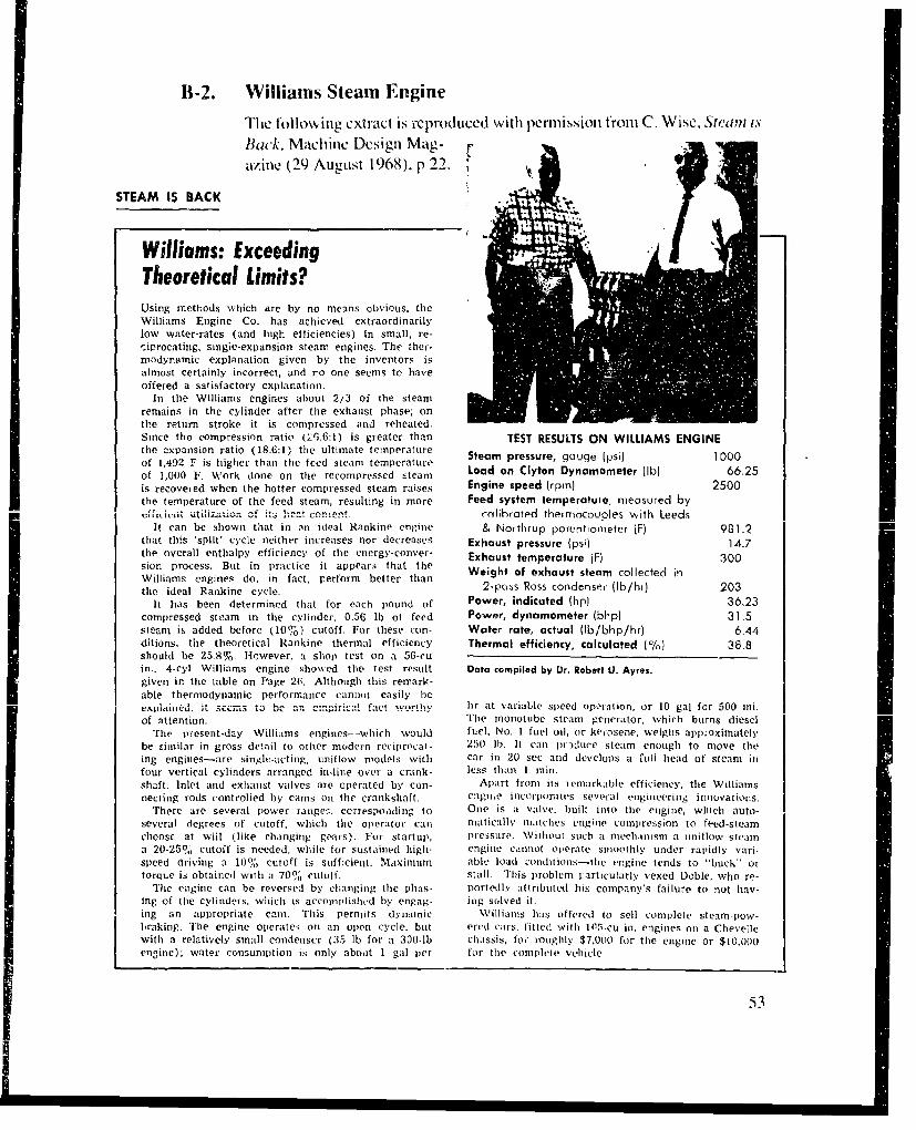
11-2. Williams Steam Engine
The following extract is ceproduced with permission from C_ Wise, Steam is
Back, Machine Design Mag-"razine (29 August 1968), p 22.
STEAM IS BACK
Williams: ExceedingTheoretical Limits?Using methods which are by no means obvious, theWilliams Engine Co. has achieved extraordinarilylow water-rates (and high efficiencies) in small, re-ciprocating, single-expansion steam engines. The ther-modynamic explanation given by the inventors isalmost certainly incorrect, and ro one seems to haveoffered a satisfactory explanation.
In the Williams engines about 2/3 of the steamremains in the cylinder after the exhaust phase; onthe return stroke it is compressed and reheated.Since the compression ratio (26.6:1) is greater than TEST RESULTS ON WILLIAMS ENGINEthe -xpansion ratio (18.6:1) the ultimate temperature Steam pressure, gouge (psi) 1000of 1,492 F is higher than the teed steam temperatureof 1,000 F. Work done on the recompressed -:team Load on Clyton Dynamometer (lb) 66.25
is recovejed when the hotter compressed steam raises Engine speed (rpm) 2500the temperature of the feed steam, resulting in more Feed system temperature, measured by-eLtlit utilzaution of it.: !rat conto.c rnlihraterd theimrocoucles with Leeds
It can be shown that in an ideal Rankine engine & Northrup porentiometer iF) 981.2that this 'split' cycle neither increases nor decreases Exhaust pressure (psi) 14.7the overall enthalpy efficiency of tile energy-conver- Exhaust temperature (F) 300sion process. But in practice it appear.; that the Weight of exhaust steam collected inWilliams engines do, in fact, perform better thantihe ideal Rankine cycle. 2-poss Ross condenser (Ib/hr) 203
It has been determined that for each pound of Power, indicated (hp) 36.23compressed steam in the cylinder, 0.56 lb of feed Power, dynamometer (blip) 31.5steam is added before (10%) cutoff. For these con- Water rate, actual (lb/bhp/hr) 6.44ditions, the theoretical Rankine thermal efficiency Thermal efficiency, calculated (0) 38.8should be 25.8%. However, a shop test on a 56-cuin.. 4-cyl Williams engine showed the test result Data compiled by Dr. Robert U. Ayres.given in the table on Page 26. Although this remark-able thermodynamic performance cannot easily bee.p... ied, it s"cms tb an cempxrWcl fact wort h".hr at variable speed operation, or 10 gal for 500 mi.of attention. The monotube steam generator, which burns diesel
The present-day Williams engines--which would fuel, No. I fuel oil, or kerosene, weighs app:oximatelybe similar in gross detail to other modern reciprocat- 250 lb. It can llraduec steam enough to move theing engines-are single-acting, unitlow models with car in 20 sec and develops a full head of steam infour vertical cylinders arranged in-line over a crank- less than I loin.shaft. Inlet and exhaust valves are operated by con- Apart front its nenmarkable efficiency, the Williamsnecting rods controlied by cams on the crankshaft. engiei, iltcorporates several engineering innovations.
There are several power range:;, cerrespoading to One is a valve, built into the engine, which auto-several degrees of cutoff, which the operator can nraticall, niatlches engilne comnpression to feed-steamchoose at wiil (like changing gears). For startup, pressure. Without such a niechanim a initlow steama 20-25% cutoff is needed, while for sustained high- engine cannot operate smoothly tinder rapidly vari-speed driving a 10% cutoff is sufficieilt. Maximum able load c'onditions-tlie engine tends to "buck" ortorque is obtained with a 70% cutuff. stall. This problem particularly vexed Doble, who re-
The engine can be reversed by changing the plhas- portedly attributed his company's failure to not hav-ing of tihe cylinders, which is accomndishtd by engag- ing solved it.log an appropriate earn. This pernoits dynamic Williams has offered to sell complete steanm-pow-braking. The engine operates on an open cycle, but ered cars, fitted with 105-cu it. engines on a Chevellewith a relatively small condenser (35 lb for a 300-lb chassis, for roughly $7.000 for the engine or $10,000engine); water consumption is only aboat 1 gal per for the complete vehicle
53

B-3. Bolz's Analysis of Liquid Thermal Engine Performance
The following extract is reproduced from a paper (Liquid Thermal Engin,Internal Report No. 1258, 11 May 1960). obtained from the ClevelandPneumatic Tool Company of Cleveland, OH, in 1960. The analysis makesreference to data on acetone obtained from P. W. Bridgeman.1
IN
11). It. RBii(,'crnun. Thermodyvnamnic Propcrues of Twelve Liquids Ifetween 20' 80', and up to 12,000 KGMIVsq-cn8. Pwoc.
54
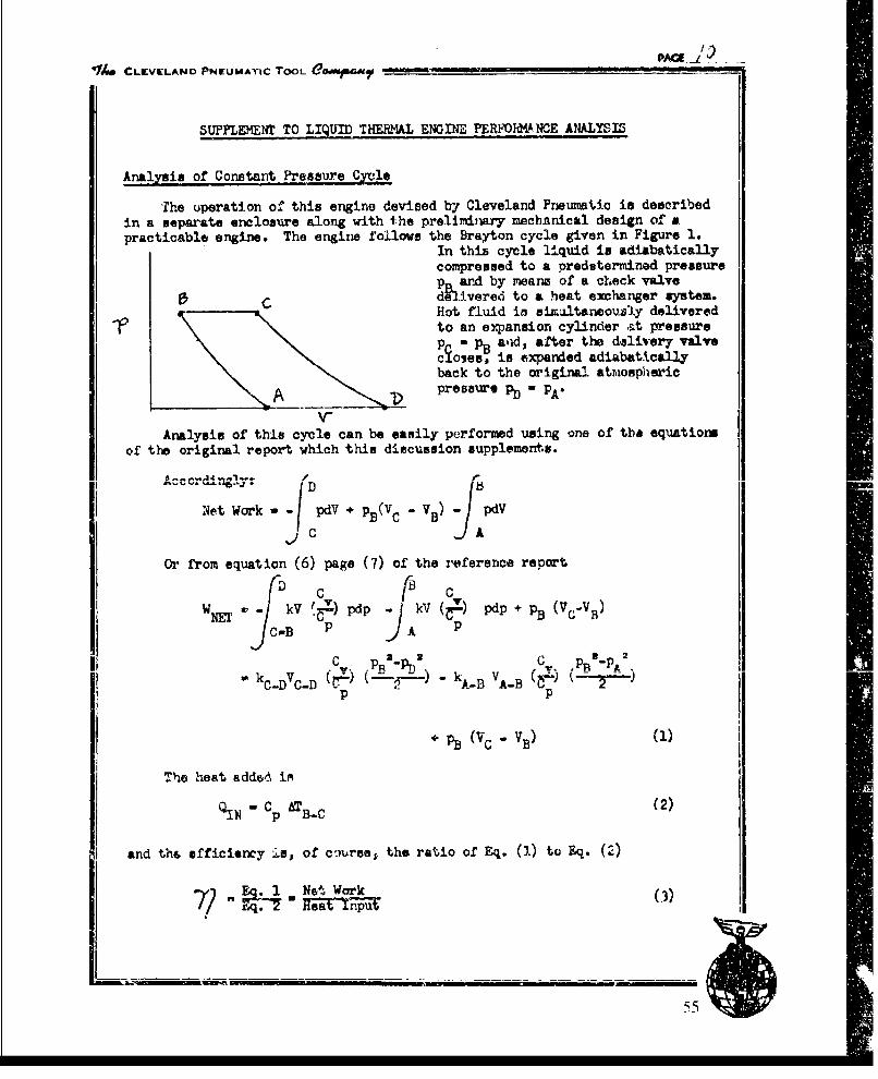
p~ jik---PAMe -L i
v14 CLEVELAND PNEUMATIC TOOL OGMPWftfIb --
SUPPLEMENT TO LIQUID THEILMAL ENGINE PERFOW . HNCE ANALYSIlS
Analyaia of Constant Pressure Cycle0
The operation of this engine devised by Cleveland Pneumatic is describedin a separate enclosure along with the preliminary mechanical design of apracticable engine. The engine follows the Brayton cycle given in Figure 1.
In this cycle liquid is adiabaticallycompressed to a predetermined pressurep and by means of a check valvedCd.ivered to a heat exchanger system.Hot fluid in airmultaneously delivered
1to an expansion cylinder at pressurep" pB alid, after the delivery valvecioses, is expanded adiabaticallyback to the original atmiospheric
A pressure pD - pl_
Analysis of this cycle can be easily performed using one of the equationsof the original report which this discussion supplements.
Ac crdi1ngly [
Net Work - pdg + pBV C -VB
Or from equation (6) page (7) of the reference report
D C CWM kV .1-) pdp kV%.) pdp+pB(VC'VH)
C-OB P A -
C R I•-pn X. C. ,pjqf-pt2ý •
C-DhF -- kA-D VABýtP p
" pB(Vc "vB) (1)--
Tho heat added im (--
QIN - cp ATB-C (2)
and the efficiency is, of c'nurse, the ratio of Eq. (1) to Eq. (2)
E .1 N't Work (3)
7) Zq-. 0ia
-55
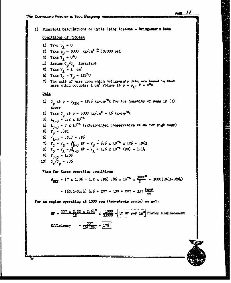
41,, CLKVIL.AND rPN4EMATIC TOOL 4160y""
I) Nmerialo Calculations of" Cyle Using Acetoom - ,ridLun'es Data
Condzitiong of Problex
1) Take PA a 02) TaJw N- 3000 kgIona -V L3,O00 psi
3) Tak TA - oC
4) Assu C V/C invariant
5) Take VA I ce
6) Take TC TB - 1250C
7) The unit of maas upon which Bridgeman' s data are based in thatmass which occupies 1 cx3 volume at p a pA' T - O°C
Data
I) Cp at p a PATM - 19.5 kg-cn°/k for th. quantity of mass in (7)
above
2) Take Cp at p - 3000 kg/ca' - 16 kg-on/°k3) kA.B " -2= x 160"I•) _- = 7 X 10⁻⁶ (,rrtar.naoltad nonnevative value for high tam)I" -- ;.I) . . . .. . "- -.. . . . . . . . . . .. - ....
5) VS .894k6) VA.B - .907- .95
7) VC-VB * L ATVB+ 5.5;zx014 x12 125 .963
8) vD a VA +A-D AT - VA+ 1.6x 10⁻³ (90). 1.14
9) V ,, 1.O5
1o) c,/cp .86
Then for these operating conditions
WNr a (7 x 1.05 - 4.2 x .95) .86 x 10"- x 1- + 3000(.963-.894)
- ( 63.4-3A.I4) L.5 + 207 - 130 + 207 a 337 E&cMcc
For an engine operating at 1000 rpo (two-stroke cycle) we get:
Hp.3 2L.L2z2 1 2A 100 Piston Displ.acesent
Efficiency 17
56

"*IM CLEV LAND PNEUMATIC TOOL O@ ,, - .....
II) a Seond Example An @ AT a 20 0 C
Conditions of Problem
A other conditions are the sw asa in (I).
Data
1) C during heat input stroke take as 16 kg-c/°k
2) kp•. - .2 x 10o'
3) kC- a 8 x 10⁻⁶ (conservative extrapolation)
4) VB - .894
5) VA.B- . 9 5
6) VC =VB+ 5.5 x10"4 x200 a 1.00
7) VD o VA 1.6x 3 x 150 - l.24
8) VToD .1.129) c./cp..86
Not Work o (8 z 1.12 - 4.2 x .95) .86 x 10" x + 3000(1.00-.B894)
w 193 + 316 - 511 kg-cm
- j•".j,}t 1000 rp engine speed
These efficienoes are without regernrationo It is felt that with goodregeneration this efficiency may be increased by 50% and theoretical valuesof 25% obtained. Again, I feel that frictional losses in the cylinder andheat exchangers will not be large and with good valving a reasonable portionof the theoretical efficiency may be obtained--perhaps 15% to 17% for thecycle efficiency.
Be part of the engine, as designed to date by Cleveland Pneuatic,appears to present ay Insurmountable engineering problems. Ingenuity andexperimntal experience are nocee•ry to minimise engine and heat transfersi.es and weights and the ability to cope with th. high pressures neededfcr good efficiency is, I believe, just a matter of experience.
,V .. _57
Appendix C. Calculations to Determine Preliminary Size ofVapor-Cycle Engine and Power System Components
59
ContentsPage
C -i. Engine Size ................................ ...................... .......61C-2. Steam Generator Size........................................................................... 62C-3. Fuel Tank Sizeý.................................................................................. 63
60
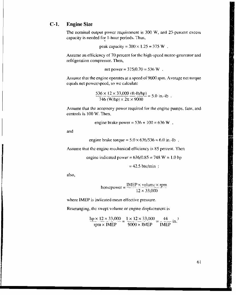
C-1. Engine Size
The nominal output power requirement is 300 W, and 25-percent excesscapacity is needed for I-hour periods. Thus,
peak capacity = 300 x 1.25 = 375 W
Assume an efficiency of 70 percent for the high-speed motor-generator andrefrigeration compressor. Then,
net power = 375/0.70 = 536 W
Assume that the engine operates at a speed of 9000 rpm. Average net torqueequals net power/speed, so we calculate
536 x 12 x 33,000 (ft-lb/hp) = 5.0 i.-ib746 (W/hp) x 21t x 9000
Assume that the accessory power required for the engine pumps, fans, andcontrols is 100 W. Then,
engine brake power = 536 + 100 = 636 W
and
engine brake torque = 5.0 x 636/536 = 6.0 in.-lb
Assume that the engine mechanical efficiency is 85 percent. Then
engine indicated power = 636/0.85 = 748 W = 1.0 hp
= 42.5 btu/min
also,
!MEPP-z volume × rpmhorsepower =M
12 x 33,000
where IMEP is indicated mean effective pressure.
Rearranging, the swept volume or engine displacement is
hp x 12 x 33,000 - 1 x 12 x 33,000 44 in.3rpm x IMEP 9000 x IMEP IMEP
61
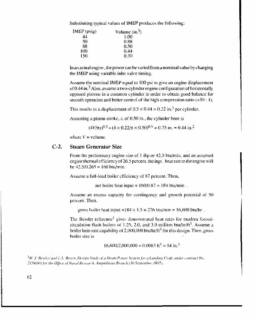
Subs;tituting typical values of IMEP produces the following:
IMEP (psig) Volume (in. 3)44 1.0050 0.8888 0.50
100 0.44150 0.30
In an actual engine, the power can be varied from a nominal value by changingthe IMEP using variable inlet valve timing.
Assume the nominal IMEP equal to 100 psi to give an engine displacementof 0.44 in.3 Also, assume a two-cylinder engine configuration of horizontallyopposed pistons in a common cylinder in order to obtain good balance forsmooth operation and better control of the high compression ratio (=30 : 1).
This results in a displacement of 0.5 x 0.44 = 0.22 in. 3 per cylinder.
Assuming a piston stroke, s, of 0.50 in., the cylinder bore is
(4V/Its).-5 = (4 x 0.22/,t x 0.50)0.5 = 0.75 in. = 0.44 in. 2
where V = volume.
C-2. Steam Generator Size
From the preliminary engine size of I ihp or 42.5 btu/min, and an assumedengine thermal efficiency of 26.5 percent, the inpt heat rate to the engine willbe 42.5/0.265 = 160 btu/min.
Assume a full-load boiler efficiency of 87 percent. Then,
net boiler heat input = 160/0.87 = 184 btu/min
Assume an excess capacity for contingency and growth potential of 50percent. Then.
gross boiler heat input =184 x 1.5 = 276 btu/min = 16,600 btu/hr
The Bcssler reference t gives demonstrated heat rates for modern forced-circulation flash boilers of 1.25, 2.0, and 3.0 million btti/hr/ft3 . Assume aboiler heat-rate capability of 2,000,000 btu/hr/ft 3 for this design. Then, grossboiler size is
16,600/2,000,000 = 0.0083 ft3 = 14 in. 3
1W.I. e.slr ajad .i. L Boyten. Design Study q.fa Stcan Pol'er Systeimjr a Landing O C Jt. un1h, contrw,' No.
2159(O0)J)r the Olftic oJ Naval Research. AmpnJihiios Branch (30 September 1957).
62

Since this is a small-scale design, assume a size of double this volume, or anet boiler size of 28 in. 3 This is equivalent to a shape of 3 in. in diameter and4 in. long.
From Keenan and Keyes, 2 steam at 1200 psi and 1 000°F has an enthalpy of1500 btu/lb. Thus, the peak steam rate is
16,600 x 0.87/1500 = 9.6 lb/hr
This allows enough steam for an engine efficiency as low as
42.5 btu/min/ihp x 60 min/hr x 1 ihp = 17.7%1500 btu/lb x 9.6 lb/hr
C-3. Fuel Tank Size
Assume that diesel fuel has a heating value of 19,000 btu/lb and a specificvolume of 30 in.3/lb. This results in a heating value density of =633 btu/in. 3
At a peak boiler heat rate of 16,600 btu/hr, the peak fuel rate will be
16,600/633 = 26 in.3/hr
The nominal fuel rate is
166 avg W/day 16,600 btu/hr peak rate 1_i
375 peak W/day 1.5 contingency factor 633 btu/in.3
= 7.74 in.3/hr = 186 in./day .
This results in preliminary tank sizes for one day of 6 x 12 x 2.6 or 6 x 8 x 3.9in. At 231 in. 3/gallon, these example tanks would hold about 0.8 gallon.
,11. tl. Keenan and F. G. Ke.'es. Thrrniowdnami" Prolprtics iJ'Steani, John Wih'y & Sols (I 936).
63

Appendix D. Analysis of Vapor-Cycle and SteamEngine Performance
565
ContentsPage
D -1. Introduction ...................................................................................................................... 69D -2. Baseline Conditions ...................................................................................................... 70
D -2.1 A dm ission Process ............................................................................................... 71D -2.2 Exhaust Process ................................................................................................ 71D -2.3 Exhaust Pressure ................................................................................................... 72D -2.4 Feed-Steam Conditions ................................................................................... 72D -2.5 Engine Com pression Ratio ............................................................................... 73
D -3. A nalysis Process ........................................................................................................... 74D -4. Engine Cycle Therm odynam ics ................................................................................... 76
D -4.1 Com pression A nalysis ...................................................................................... 76D -4.2 Adm ission A nalysis ........................................................................................... 77D -4.3 Expansion Analysis ........................................................................................... 78D -4.4 Exhaust Analysis ............................................................................................... 79
D -5. V apor-Cycle Therm odynam ics ................................................................................... 79D -5.1 Pum p W ork ...................................................................................................... 80D -5.2 Engine W ork .................................................................................................... 80D -5.3 Ideal Therm al Efficiency w ith Engine .............................................................. 80D --).4 Ihennal Etficiency w ith l'urbine Expander .......................................................... 8iD -5.5 Incom plete Expansion Process .......................................................................... 81D -5.6 Carnot Therm al Efficiency .............................................................................. 82
D-6. Comparison of Performance at Various Operating Conditions ................................... 83D -7. Losses in Therm odynam ic Cycle ................................................................................. 87
D -7.1 Condenser Losses ............................................................................................. 87D -7.2 Pipe, Pum p, and V alve Losses .......................................................................... 87D -7.3 Engine Losses .................................................................................................... 88
D-8. Conclusions and Observations .......................................... 9...... 9
D -9. Recom m endations ............................................................................................................. 90
References ..................................................................................................................................... 92
67
Figures
D-1. Simple steam power plant and Rankine vapor cycle ..................................................... 69D-2. Single-expansion uniflow steam engine cycle ................................................................ 70D-3. Admission process for steam engine analysis ................................................................ 72D-4. Exhaust process for steam engine analysis ..................................................................... 72D-5. Results of steam com pression analysis .......................................................................... 73D-6. Process for calculation of mean effective pressure for steam engine ............................. 75D-7. Analysis for incomplete-cxpansion engine losses ......................................................... 82D-8. Selected results from vapor-cycie power system analysis ............................................. 86D-9. Ideal engine cycle diagram and estimate for realistic diagram ...................................... 88
Table D 1. Summary of results for vapor-cycle engine and power system analysis ............... 84
68
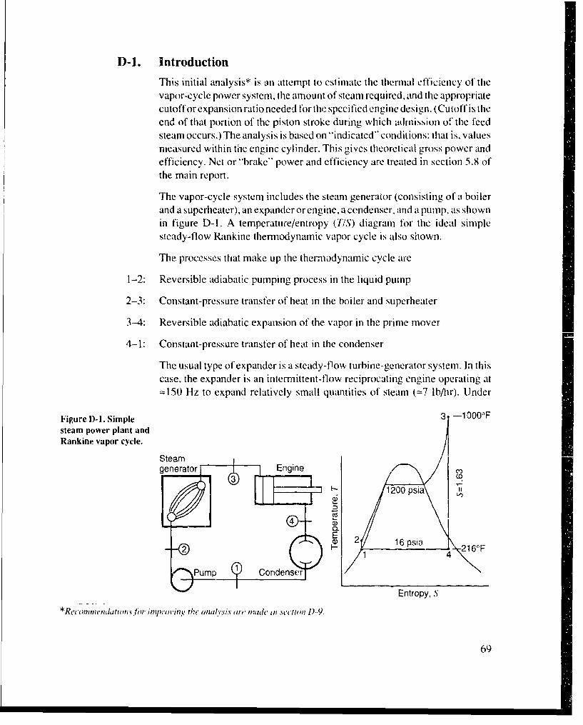
D-1. Introduction
This initial analysis* is an attempt to estimate the thermal efficiency of thevapor-cycle power system, the amount of steam required, and the appropriatecutoff or expansion ratio needed for thi, specified engine design. (Cutoff is theend of that portion of the piston stroke during which admission o" the feedsteam occurs.) The analysis is based on "Indicated" conditions: that is, valuesmeasured within the engine cylinder. This gives theoretical gross power andefficiency. Net or "brake" power and efficiency are treated in section 5.8 ofthe main report.
The vapor-cycle system includes the steam generator (consisting of a boilerand a superheater), an expander or engine, a cendenser, and a pump, as shownin figure D-1. A temperature/entropy (TIS) diagram for the ideal simplesteady-flow Rankine thernodynamic vapor cycle is also shown.
The processes that make up the thermodynamic cycle are
1-2: Reversible adiabatic pumping process in the liquid pump
2-3: Constant-pressure transfer of heat in the boiler and superheater
3-4: Reversible adiabatic expansion of the vapor in the prime mover
4-1: Constant-pressure transfer of heat in the condenser
The usual type of expander is a steady-flow turbine-generator system. In thiscase, the expander is an intermnittent-flow reciprocating engine operating at=150 Hz to expand relatively small quantities of steam (=7 lb/lr). Under
Figure D-1. Simple -1 000°Fsteam power plant andRankine vapor cycle.
Steamgenerator -Egn()
Entropye
k 1200 psia
I-I
4
op~~Entopy nSnen
*Rei oiniendtions lhIr )inirvnthe' I anulvsit arv Pnide In whNetm D)-9.
69

steady-state conditions, thle engine behavcs in a fashion simlilar to thle ILIrbi le,as tar as selection and analysis of a Rankine thermrodynaimic vapor cycle isconcerned.
The type of steam- engine to be analyzed is a hilgh-compression, unitlow.51 ngle-expanisioi. essentially noncondensing (sec sect. D-4) system operat -ing on high-pi-essure, super-hecated vapor. The engine also operates in a cyclicfashion, as illustrated in figure D-2. Here the ideal pressure/volume (P/I')
diagrani is simillar to that for the ideal air-standard diesel engine thermiody-namic cycle, except that it is not at true thermodynamic vapor cycle, as shownby tile vertical line onl tile TIS diagram.
Ideally the engine cycle consists of four stages:
1-2: at reversible adiabatic compression process, where thie residual exhaust steamlleft in the cylinder is compressed to high pressure and temperature, asdetermined by the exhaust steam properties and the volumietric compressionratio of the enoine
2-1: a constant-pressure admission of steami from the boiler* through valves in thecylinder head
i-: reve rsibleijbtccp~ino h awift~ yidratruofo theadmission process and until rcleasc ofthlle steam to the exhaust process
4-1: a1 constant-voIlume exhaust process. where expanded steam escapes into thlecondenser through ports uncovered at the hottom ot the cylinider
D-2. Baseline Conditions
Before detailed analysis can begin, several parameters and elemnent,, of theengine operating cycle need to be established. These are thle admissionprocess, thle exhaust process, thle exhaust pressure, the feed-steam pressure
Figtire D)-2. Single- TAdmissionexpansion1 uiiiflow steatmIeninei cycle. AmsinExpans;ion
2A 3-Cssoo f2 3 -utoffC
C
Wk ~ Compression
Co4 ~- Release 0-
Exhast 1Exhaust
Volume. IEntropy. NStroke
`A l vi-II e 10 /0l/el' IA% ii. d //I plac e o/ tii h i nwc 1 il Fh1) Ae'h-I' /1Itl F t/i., tte I -
70)
and temperature, and the engine compression ratio. First, assume that steady-state conditions prevail, and that compression and expansion occur along acommon entropy line, as illustrated in figure D-2 (on the right) and the normalsimple Rankine cycle for turbine-type expanders (fig. D- ]). Thus, propertiesof the residual exhaust steam in the cylinder, as the exhaust port closes,determine the entropy value for the steady-state engine cycle. Conversely. theamount of steam admitted to mix with the compressed exhaust steamndetermines the properties of the residual steam at the end of the exhaustprocess.
D-2.1 Admission Process
Assume for this analysis that the engine compression ratio is such that tileresidual exhaust steam is compressed along this entropy line to a pressurecondition that is lower than the feed-steam pressure from the boiler.* Theadmission process, where the incoming steam mixes with the compressedexhaust steam, can be handled in different ways. The method selected for thisanalysis is illustrated in figure D-3. It assumes that there is no throttling of theincoming steam to a lower pressure (this is treated in sect. D-7.2), and thatthere is no pressure drop during admission. Tht s, the admission processoccurs at the feed-steam pressure condition of 1200 psia.
As shown in the Mollier (hIS) diagram ot figure D-3, mixing during theadmission process increases the enthalpy (Ih) and temperature of the com-pressed exhaust steam, and decreases the enthalpy and temperature of the feedsteam until the thermodynamic balance defining the end of admission andbeginning of expansion, point 3 or cutoff, is reached. Larger cutoffs (longeradmission period) allow more boiler steam to enter, thereby changing the heatbalance and determiningt the final entropy for the expansion process. Thus, adifferent entrcpy line for operation is defined for each new value of cutoff.Each new value of cutoff also determines a new value of mean effectiveprCS UC or Io •-•c powv er tfIor t.Ih C Ie -n,, ,Inea I .; .1 i 6tId o D1 -T 6.
D-2.2 Exhaust Process
The exhaust process can also be handled in different ways. The methodselected forthis analysis was adapted fronm it diesel engine exhaust p-ocess [ I ]and is illustrated in the h/S diagram of figare D-4. As shown, the steam thatescapes through the exhaust ports at release is assumed to be throttled 121 atconstant enthalpy to the selected exhaust back-pressure condition. It thenflows to the condenser. The steam that remains within tile cylinder is assumedto expand isentropically to the exhaust back-pressure condition. It is thencompressed, without further condensation (see sect. D-4). tront this condi-
tioll.
*(Crom p( "Io(' to pF ? cs rc)'..gr•e• ,,rC r'r tha. ol e 'ntfill to h l/0l /•r1'.e'A IC L% d/im." '.". 'di in.cions 1-2 . . a)-s. MVnd 1)-9.
I11
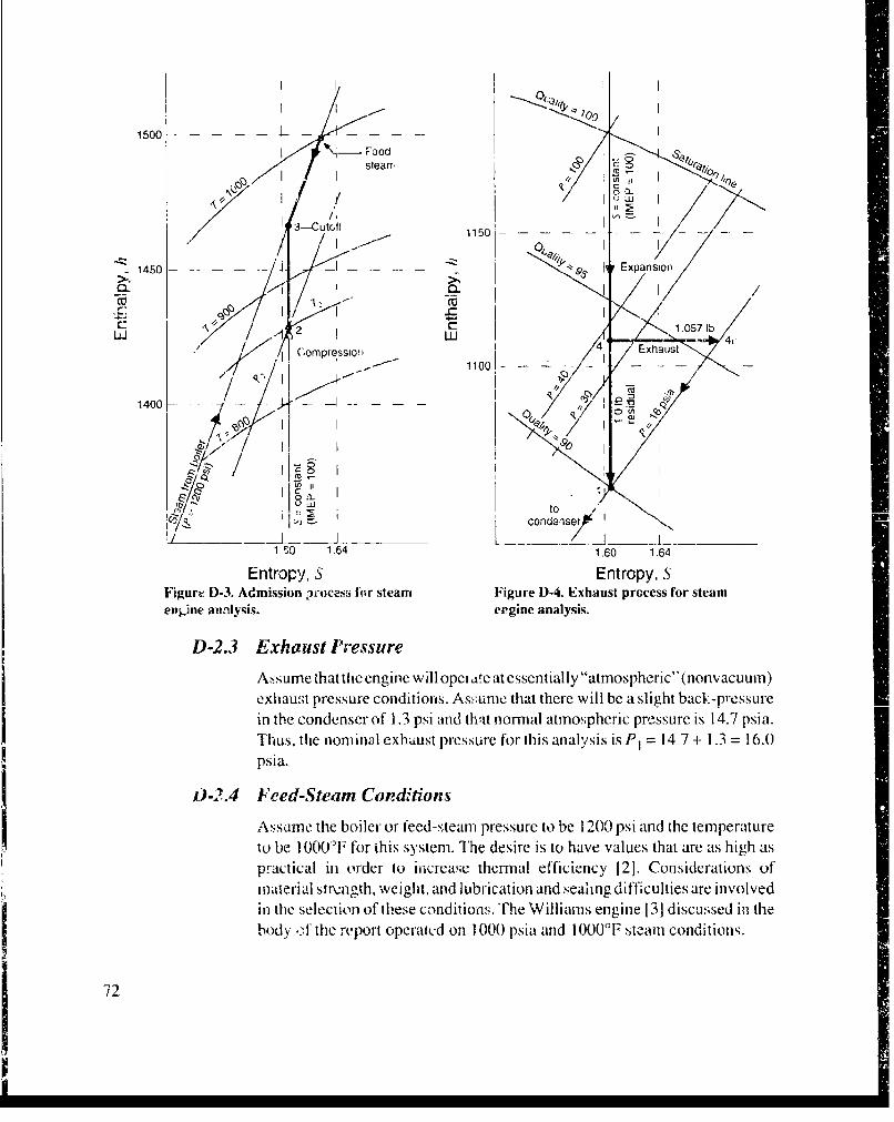
1500 - - - - - L - - - - -
stearl / /II 1/0
3-cuto( 1150I 3O ,, 1150 - - -. - - - - -
1450- F---- - Expansion,
r--I 4 "x2 I I.4
LI.J // ;ompressloI' m r .i! 1100 1- -- -
140 - K "--
oto
lc IIIcy~ I condenser
1 S0 1.64 1.60 1.64
Entropy, S Entropy, SFigure D-3. Admission rtocess for steam Figure D-4. Exhaust process for steamengine aunlysis. esgine analysis.
D-2.3 Exhaust Pressure
Assume that the engine will opeii ,e at essentially "atmospheric" (nonvacuum)exhaust pressure conditions. As•:ucni that there will be a slight back-pressurein the condenser of 1.3 psi and that normal atmospheric pressure is 14.7 psia.Thus, the nominal exhaust pressure for this analysis is P1 = 14.7 A- 1.3 = 16.0psia.
)-2.4 Feed-Steam Conditions
Assame the boiler or feed-steam pressure to be 1200 psi and the temperatureto be 1000T for ihis system. The desire is to have values that are as high aspractical in order to increa;e thermal efficiency 12]. Considerations ofmaterial sircngth, weight, and lubrication and seahng difficulties arc involvedin the selection of these conditions. The Williams engine 131 discussed in thebody , the report operat-d on 1000 psia and 1000°F steam conditions.
72
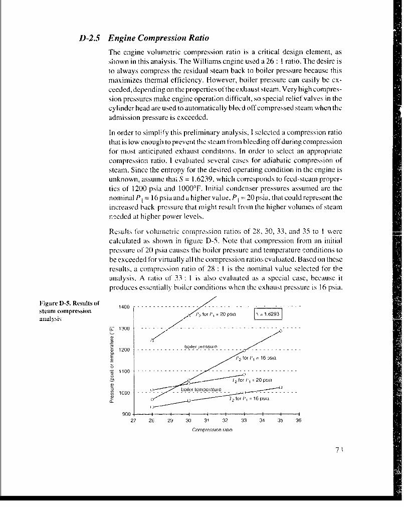
D-2.5 Engine Compression Ratio
The engine volumetric compression ratio is a critical design element, asshown in this anaiysis. The Williams engine used a 26 1 I ratio. The desire isto always compress the residual steam back to boiler pressure because thismaximizes thermal efficiency. Hlowever, boiler pressure can easily be ex-ceeded, depending on the properties of the exhaust steam. Very high compres-sion pressures make engine operation difficult, so special relief valves in thecylinder head are used to automatically bleed off compressed steam when theadmission pressure is exceeded.
In order to simplify this preliminary analysis, I selected a compression ratiothat is iow enough to prevent the steam from bleeding off during compressionfor most anticipated exhaust conditions. In order to select an appropriatecompression ratio, I evaluated several cases for adiabatic compression ofsteam. Since the entropy for the desired operating condition in the engine isunknown, assume thai S = 1.6239, which corresponds to feed-steam proper-ties of 1200 psia and 1000'F. Initial condenser pressures assumed are thenominal P1 = 16 psia and a higher value, P1 = 20 psia, that could represent theincreased back-pressure that might result from the higher volumes of steamr. eded at higher power levels.
D,,..1s •,r . ., , ,.. , corpro.sion ratios of' 2 , -, and. 35. to 1. wer1
calculated as shown in figure D-5. Note that compression from an initialpressure o1 20 psia causes the boiler pressure and temperature conditions tobe exceeded for virtually all the compression ratios evaluated. Based on theseresults, a compression ratio of 28 :1 is the nominal value selected for theanalysis. A ratio of 33 1 is also evaluated as a special case, because itproduces essentially boiler conditions when the exhaust pressure is 16 psia.
Figure D-5. Results of 1400 [73-----steam compression f tor 11, = 20 Psia N = 1.6293O
1.13 0 . . . . . . . . . . . . . . . . . . .
0I 1300 -- - --- -- - - -----------------~
C1boiler pressure - - - -
P2 for P, = 16 psia
7 T2 for P, l 20 psia
ou " boiler temperature •...I "
C_ 12 for I'l = 16 psla
9 000i
900 - + -- I t -t--.--------4-- I
27 28 29 30 31 32 33 34 35 36
Compression ratio
7•
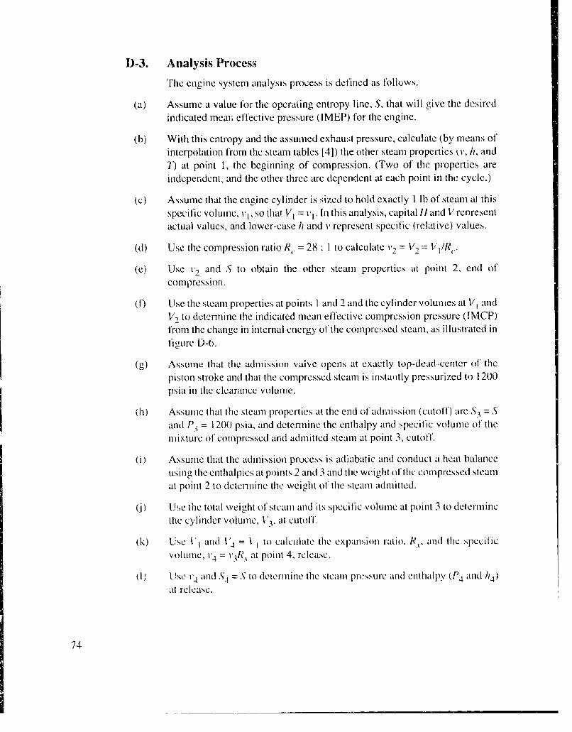
D-3. Analysis Process
The engine system analysis process is defined as follows.
(a) Assume a value for the operating entropy line, S, that will give the desiredindicated mean effective pressure (IMEP) for the engine.
(b) With this entropy and the assumed exhaw;t pressure, calculate (by means ofinterpolation from the steam tables 14]) the other steam properties (v, h, and7) at point 1, the beginning of compression. (Two of the properties areindependent, and the other three arc dependent at each point in the cycle.)
(c) Assume that the engine cylinder is sized to hold exactly 1 lb of steam al thisspecific volume, v1, so that V1 - v1 . In this analysis, capital 1I and V rcnresentactual values, and lower-case hi and v represent specific (relative) values.
(d) Use the compression ratio R. = 28 :1 to calculate v2 = V2 = 1/RC.
(e) Use v, and S to obtain the other steam properties at point 2, end ofcompression.
(f) Use the steam properties at points I and 2 and the cylinder volumes at V, andV-2 to determine the indicated mean effective compression pressure (!MCP)from the change in internal energy of the compressed steam, as illustrated intigurc D-0.
(g) Assume that the admission vaive opens at exactly top-dead-center of thepiston stroke and that the compressed steam is instaitly pressurized toI 1200psia in the clearance volume.
(h) Assume that the steam properties at the end of admission (cutoffl) are S3 = Sand P3 = 1200 psia, and determine the enthalpy and specific volume of theMixture of compressed and admitted steam at point 3, cutoff.
(i) Assume that the admission process is adiabatic and conduct a heat balanceusing the enthalpies at points 2 and 3 and the weight of the compressed steamat point 2 to determine the weight of the steam admitted.
0j) ULse the total weight of steam and its specific volume at point 3 to determ inethe cylinder volume, 1.'3, at cutoftf.
(k) Use 13 and 1'4 = t1 to calculate the expansion ratio, R., and the specificvolumC, 14 = '3R_ at point 4, release.
(I) Use v4 and "i = S to determine the steam pressure and enthalpy (P4 and 114)at release.
74
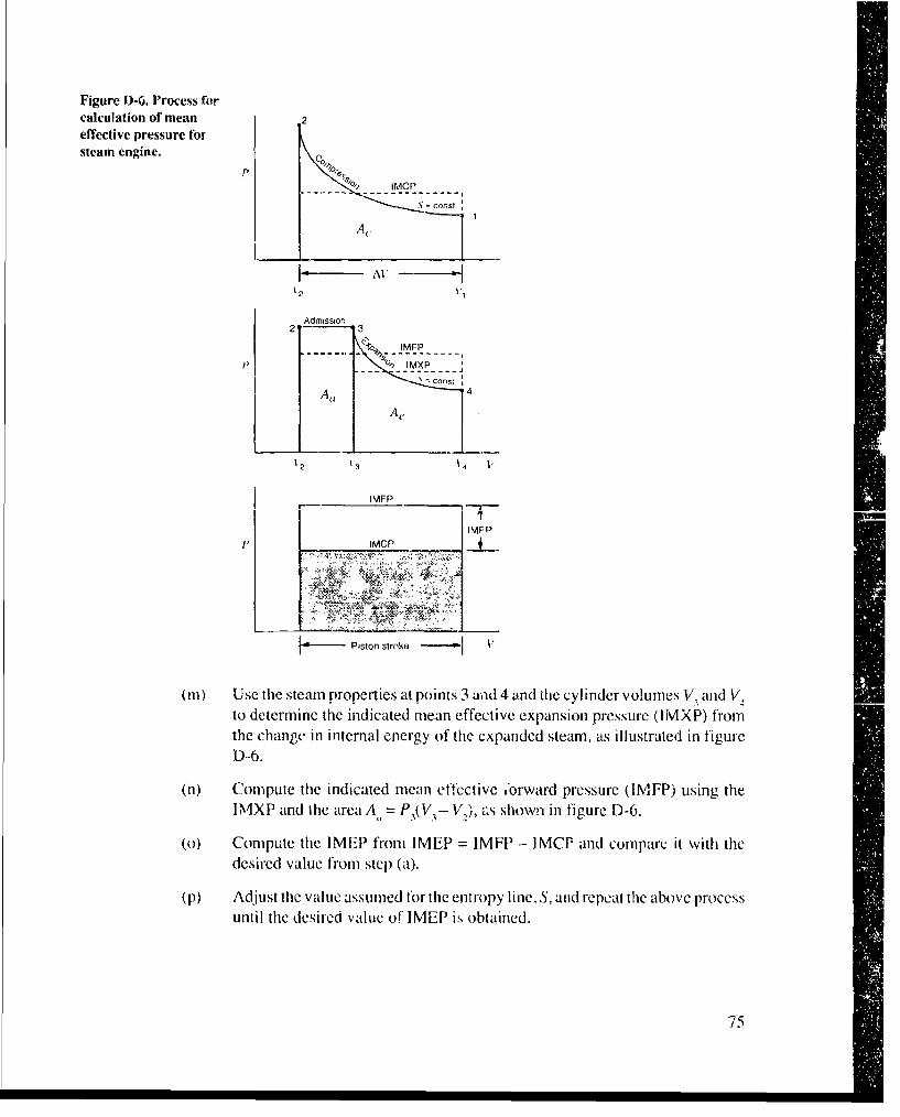
Figure D-6. Process forcalculation of mean 2effective pressure forsteam engine.
P'% IMCP
A,
Admission2 3
IMFP-S_• IMXP .
A cons; 4
12 '3 t4
IMFP
IMEP' IMCP
Piston stroke 1
(m) Use the steam properties at points 3 and 4 and the cylinder volumes V, and V,to determine the indicated mean effective expansion pressure (IIVIXP) fromrthe change in internal energy of the expanded steam, as illustrated in figureD-6.
(n) Compute the indicated mean effective *orward pressure (IFP) using theIMXP and the area A, = P3(V - V,), as shown in figure D-6.
(o) Compute the IMEP from IMEP = IMFP - IMCP and compare it with thedesired value from step (a).
(p) Adjust the value assumed for the entropy line. S, and repeat the above processuntil the desired value of IMEP is obtained.
75

D-4. Engine Cycle Thermodynamics
An example engine cycle analysis for the conditions necessary to giveIMEP = 100 psi, the nominal case of interest, is as follows. First, a value forthe entropy line is selected as S = 1.6047 (previously determined by trial anderror). With P1 = 16 psia, the other steam properties at point I are found to be
P1 = 16.0 psia,T1 = 216.3°F,1, = 22.2447 ft3/lb,h = 1054.0 btu/ib,S, = 1.6047.
Note that this steam is not superheated. Its quality is 89.9 percent (10.1-percent condensed liquid) in theory. In actual practice the steam is probablyin a supersaturated condition wherein condensation has not had a chance totake place because of the high-speed engine operation (-,150 Hz) and theslight amount of expansion into the condensation zone.
D-4.1 Compression Analysis
To obtain the conditions at point 2, assume an adiabatic (no heat transfer) and. I ,, l ýo.i , I n- , u t - n l ly -.- ..lllc • i 11 • . An -n : I, -i--
IN I M )C U IILAL 11.U Y 'Llll'ý"al P V--1N A llll1Ul(%ltllL4 j a1•.lkct on
the engine and operation at such a high speed makes this a reasonable
assumption. Also, assume that the cylinder is sized to hold exactly 1 lb ofresidual exhaust steam so that V, = 22.2447 ft3. Applying the specifiedcompression ratio, find "2 = vl1/R,. = 22.2447/28.0 = 0.7945 f3/Ilb. The other
steam properties at point 2 are found to be
P, = 926.3 psia,72 = 859.7°F,12 = 0.7945 ft3/lb,
h2 = 1427.7 btu/lb,
S2 = 1.6047.
Note that the desired pressure and temperature conditions of 1200 psia and1000°F were not reached with this low compression ratio.
The area under the compression curve for this adiabatic and thermodynami-cally closed system represents the change in internal energy, U, of the steam
caused by the compression process 15]. Internal energy is computed from theenthalpy (h) values as follows.
76

Since
h=u+pv
then
u=h-pr ,
and
A,.=fpdv=AU
So
IMCP = AU/AV = (U2 - U1)/(Vi - V2)
Since exactly 1 lb of residual exhaust steam is being compressed, WI =W2
1, VI = v1, Ul u1 , Hi = hi, and V2 = v2, etc. So,
U, = I x (1054.0 - 16 x 22.2447/5.404) = 988.14 btu
U, = I x (1427.7 - 926.3 x 0.7945/5.404) = 1291.51 btu
and
IMCP= ( 1291.51 - 988.14) x 5.404I x (22.2447 - 0.7945) -=76.43 psi
where 778.165 ft-lb/btu [6] and 144 in.2/ft2 are used to make the appropriatedimensional conversions, and 5.404 = 778.165/144.
D-4.2 Admission Analysis
To obtain the steam properties at cutoff (point 3), use the admission pressureP3 = 1200 psia, and the constant entropy value S3 = 1.6047 to interpolate forthe other three values:
3= 1200 psia,T3= 940.6°F,v3 0.6491 ft3/lb,113 1464.44 btu/lb,
S3 = 1.6047.
For an adiabatic admission process, the heat balance is
W2 112 + WjI-= ,W 2 + WJ)II,
77

where W2 is the weight of the compressed steam and W1fis the weight of thefeed steam. Propertics of the feed steam are
pt= 1200 psia,Tf= 10000 F,J,-= 0.6843 ft3/lb,Iij. 1499.2 btu/lb,
Sf= 1.6293.
Sob. ing for the relative weight of the feed steam,
W /- 113- h-,. 1464.44 - 1427.7Wf- -h- h - -1464.44-_--- = 1.057 l b/lb compressed steam
W2 11f - 13 1499.2 -1464.44
The engine cylinder volurne at cutoff is
V3 = v3(W2 + W 9) =0.6491(l + 1.057) = 1.335 ft3
which is
1.335 -- 0.794515- 0 -- = 2.52 percent of the piston stroke22.2447 - 0.7945
D-4.3 Expansion Analysis
The engine expansion ratio is
RI = V4 /V3 = VI 1V3 = 22.2447/1.335 = 16.66 : 1
The specific volume of the steam at release, point 4 in the cycle, is found byapplying R.:
v4 =Rv 3 = 16.66 x 0.6491 = I0.8128 ft3/lb
Other properties of the steam at release are found from steam table interpo-lation to be
P4 = 36.2 psia,74 = 261.3OF,"v4 = 10.8128 ft3/lb,/14 = 1110.4 btu/lb,
.54 = 1.6047.
The IMXP is found by the same process used for determining the IMCP asfollows:
IMXP = A,,/AV = AU/A V = (U 3 - U4 Vi ).. 4 - V3)
78
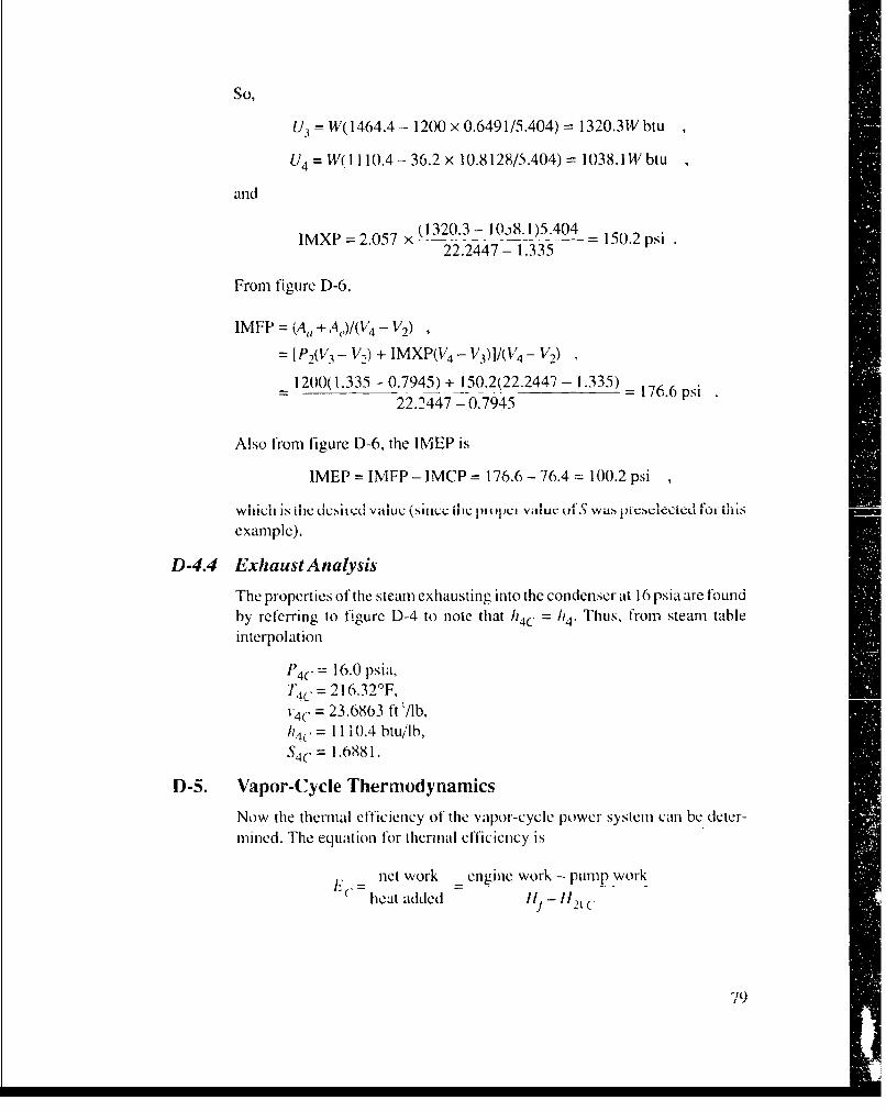
So,
U3 W(1464.4--1200 x 0.6491/5.404) = 1320.3W btu
U4 =W(1110.4-36.2x l0.8128/5.404)= 1038.lWbtu
and
IMXP =2.057 x (1 1 .1)5404= 150.2 psi22.2447- 1.335
From figure D-6,
IMFP = fA, + A4,)/(V 4 - V,)
= [P2(V3 - V12) + IMXP(V4 - V3)]/(V 4 - V2)
= 1200(1.335 -0.7945) + 150.2(22.2447 - 1.335) -176.6 psi22.2447 - 0.7945
Also from figure D-6, the IMEP is
IMEP = IMFP - IMCP = 176.6 - 76.4:= 100.2 psi
which is ihc . .. .. vu value "sim.:U HIC . .. ...i V.idu oI a, III VNCIcctcuL il L...
example).
D-4.4 Exhaust Analysis
The properties of the steam exhausting into the condenser at 16 psia are found
by referring to figure D-4 to note that 114C = /14. Thus, from steam tableinterpolation
P4 C = 16.0 psia,Tic = 216.32'F,14(' = 23.6863 ft'/lb,/14(. = 11 i0.4 btu/11,
S4('= 1.688 1.
D-5. Vapor-Cycle Thermodynamics
Now the thermal efficiency of the vapor-cycle power system can be deter-mined. The equation for thermal efficiency is
net work - engine work - pump work
heat added Hj - /12t c
79 9

where tt 2vC is the heat content of the compressed boiler feed water. Also,
IZ2vC = HL + pump work ,
where HL is the heat content of the condensed liquid at the condenser pressureof 16 psia. From the steam tables, h, = 184.4 btu/lb.
D-5.1 Pump Work
The ideal pump work, assuming adiabatic pressurization of an incompress-ible liquid, is
Ahl_2 =f v dp
The specific volume of the saturated liquid at 16 psia is 0.01674 ft3/lb. Thus,
pump work = 0.01674(1200 - i6)/5.404 = 3.67 btu/Ib
So
"h2vC = 184.4 + 3.67 = 188.1 btu/lb
The heat added in the boiler isI I Af ll 1 001. 1 I 1 1. t.Lu/.1
"--t12 VC = 1I, lfl' . 1-- 1 1.11 1 . I tU.
D-5.2 Engine Work
The theoretical engine work is found using the IMEP and the engine cyiindervolume:
work = IMEP(V4 - 1/2)/5.404 btu= 100.2(22.2447 - 0.7945)/5.404 = 397.7 btu
Or, accounting for the weight of the steam used per cycle,
specific work = 397.7/1.057 = 376.3 btu/lb
D-5.3 Ideal Thermal Efficiency with Engine
The theoretical thermal efficiency of the vapor cycle power system, at anengine operating condition of IMEP = 100 psi, is
376.3-3.67EC = 1 - = 28.42 percent1311.1
With 2544 btu/indicated horsepower-hour, the steam rate at 100 psi IMEP is
2544/376.3 = 6.76 lb/ihp-hr
80

and the heat rate is
1311.1 btu/lb x 6.76 lb/ihp-hr = 8,866 btu/ihp-hr , or
8,866/0.7457 kW/hp :-: 11,900 btu/ikW-hr
D-5.4 Thermal Efficiency with Turbine Expander
The thermal efficiency of the vapor-cycle power system using the engine asan expander can be compared to the theoretical efficiency of the simpleRankine cycle that uses a steady-flow turbine-type steam expander asfollows. Referring to figure D- 1, the steam is expanded from the boiler feedconditions along a constant entropy line Stf= 1.6293 to the condenser pressureof 16 psia, where its heat content, found from the steam tables, is
h4 R = 1070.6 btu/lb
Rankine thermal efficiency in this case is
ER - net work _ heat added - heat rejected heat rejectedheat added heat added heat added
The heat rejected in the condenser is
14R - hiL = 1070.6 - 184_4 = 886.2 btu/lb
and the heat added in the boiler is die same 1311. I btu/lb as before. So
ER = 1 886.2 = 32.41 percent1311.1
and the ratio of the engine Rankine cycle to the steady-flow Rankine cycleefficiencies is
28.42/•2,41 = 87.7 nprcent
D-5.5 Incomplete Expansion Process
The engine-type expander gives lower efficiency for the vapor-cycle powersystem than the turbine-type expander, because the engine does not fullyexpand the steam to the low 16-psia pressure level in the condenser. Thereason the engine does not use full expansion is to allow it to be more compact.The piston stroke and cylinder would have to be considerably longer thanrequired (more than two times) for a design that terminates expansion at theslightly higher pressure level of release (36.2 psia in the example above). Theloss in efficiency due to the incomplete expansion operation of the engine canbe estimated with the help of figure D-7, which is focused on a single poundor steam.
81

Figure D-7. Analysis for 1200 psi 3 h 1464.44, 0.6491incoinplete-expansioriengine losses. For 1-1b steam
I = 1.6047P 4 = h)3 - h14
1 , /13 - 114 ,1 1 _4 h =1110.4, v 10.8128, P = 36.2
W,(, 4 - I' d ' 4 ('14 - h 1 ) - ( 4 - P1 ) X 4- - I? = 1054.0 •16 psi v= 22.24 4 7
Note that the additional specific work, represented by the area of the completeexpansion 'triangle," is
(h4 - h1 ) - (PZ-- P 1)v4 /5.404
= 0 110.4- 1054.0)- (36.2- 16)10.8128/5.404 = 16.0 btu/ib
With this extra work accounted for in the full-expansion engine cycle,* thenew specific engine work is
397.7 + 2.057 x 16.0 _ 407.4 btiu/lb
1.057
and the theoretcal therma! effic,,-Cy E'. be oe..
E,. = (407.4 - 3.67)/1311.1 = 30.79 percent
compared to the incomplete expansion value of 28.42 percent. The remainderof the losses, compared to the steady-flow Rankine vapor-cycle value of'32.41 percent, are likely due to the incomplete compressiont and theadmission mixing processes.
D-5.6 Carnot Thermal Efficiency
Another comparison of the vapor-cycle system performance i, obtained fromi[
the theoretical thermal efficiency of the ideal Carnot thermodynamic cycleoperating between the same temperature extremes:
"TL 216.32 + 460(E(, I -7"1 = I - 1000 + 460 -= 53.68 percent
"'Notei that .iecial c khauixt valvin, w:,'ud be requ 'ired to cXja*nd all Ih' steami to 1(1 p1l a ald to, olprn',S.- on/y 1 I1)bbaI(A (uo nar boin/i', ,i'ithiu',i
÷Ali e//1 t',ii T v( '.Y 4 ;percent i.% obtained jitr the OI) -p.1i IA .l' inl anilhct' c.1panlimal I Ih' when a (n.q'rt.%iolnratio ol 33 i. ll.wd.
82
j]--
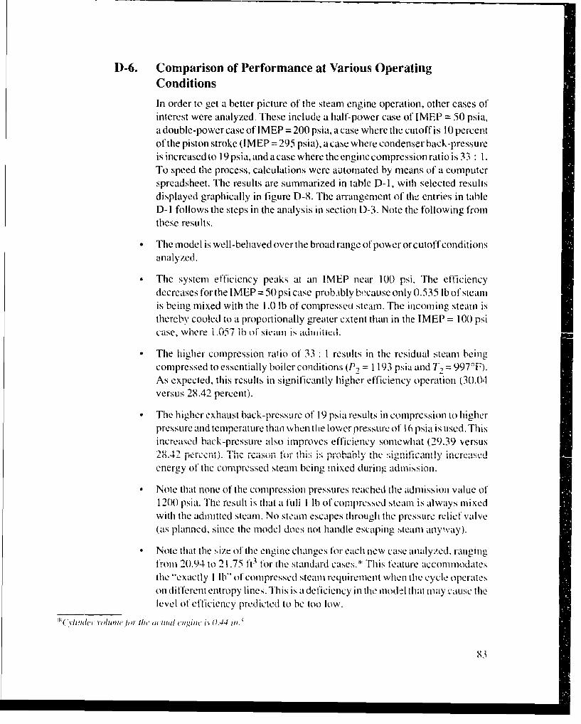
D-6. Comparison of Performance at Various OperatingConditionsIn order to get a better picture of the steam engine operation, other cases ofinterest were analyzed. These include a half-power case of IMEP = 50 psia,a double-power case of I MEP = 200 psia, a case where the cutoff is 10 percentof the piston stroke (IMEP = 295 psia), a case where condenser back-pressureis increased to 19 psia, and a case where the engine compression ratio is 33 : 1.To speed the process, calculations were automated by means of a computerspreadsheet. The results are summarized in table D-1, with selected resultsdisplayed graphically in figure D-8. The arrangement of tht_ entries in tableD- 1 follows the steps in the analysis in section D-3. Note the following fromthese results.
"* The model is well-behaved over the broad range of powerorcutoffconditionsanalyzed.
" The system efficiency peaks at an IMEP near 100 psi. The efficiencydecreases for the IMEP =50 psi case probably bhecause only 0.535 lb of steamis being mixed with the 1 .0 lb of compresserI steam. The incoming steam isthereby cooled to ia proportionally greater extent than in the IMEP = 100 psicase, where i .05 /ib 1o sicain is aduiiico.
" The higher compression ratio of 33 :1 results in the residual steam beingcompressed to essentially boiler conditions (P-, = 1193 psia and T-, = 997°F).As expected, this results in significantly higher efficiency operation (30.04versus 28.42 percent).
" The higher exhaust back-pressure of 19 psia results in compression to higherpressure and temperature than when the lower pressure of 1 6 psia is used. Thisincreased back-pressure also improves efficiency somewhat (29.39 versus"2i4 pret). The~r~-'L.'I-- 4ea ,-n f -:- ;,- ' -- ' -a ly•n.,,,, per.,l 1101 . ..... ,-.. ,. .. ..... I I,,•,,.,a ,
energy of the compressed steam being mixed during admission.
" Note that none of the compression pressures reached the admission value of1200 psia. The result is that a full 1 lb of compressed steam is always mixedwith the admnitted steam. No steam escapes through the pressure relief valve(as planned, since the model does not handle escaping steam anyway).
" Note that the size of the engine changes for each new case analyzed, rangingfrom 20.94 to 21 .75 ft3 for the standard cases.* This feature accommodatesthe 'exactly I Ib" of compressed steam requirement when the cycle operateson different entropy lines. This is a deficiency in the model that may 2muse thelevel of efficiency predicted to be too low.
• 'hth e J,.o the. actial ent'ii( ij 0.44 in.
83
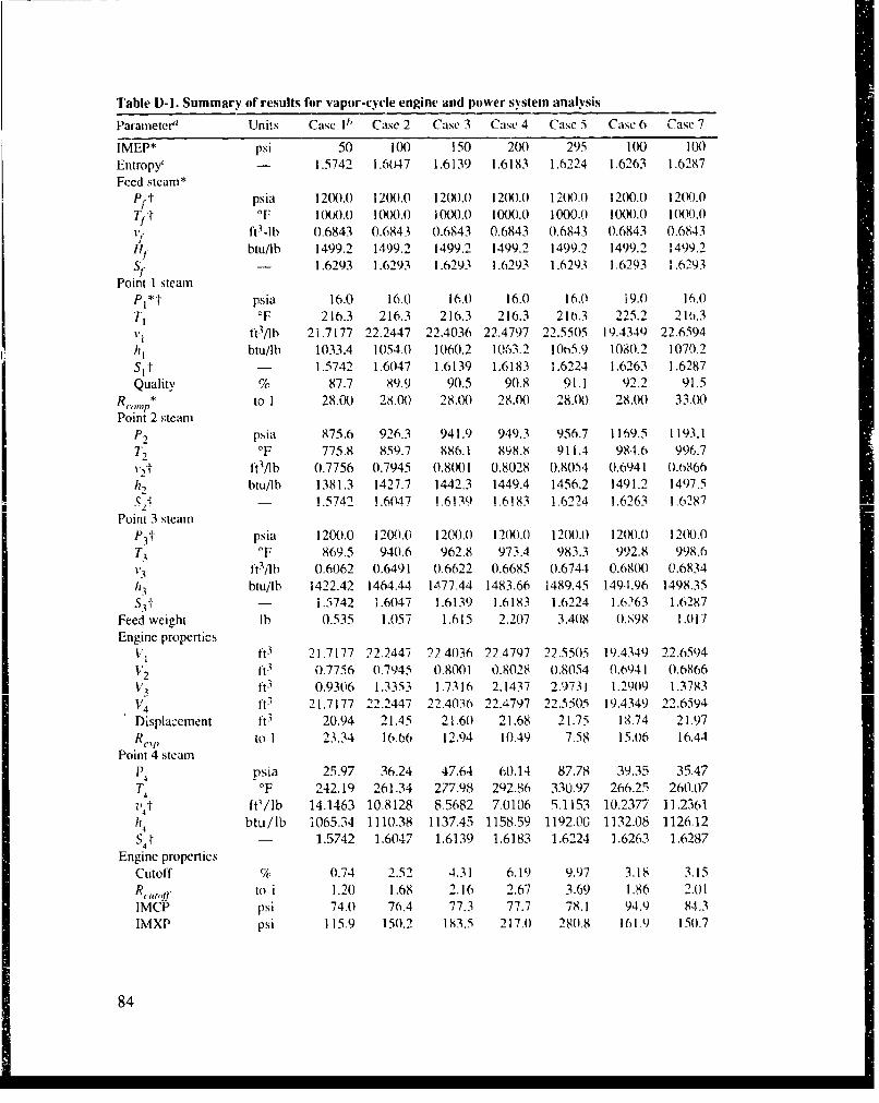
Table D-I. Summary of results for vapor-cycle engine and power system analysis
Parameteira Units Case II' Case 2 Case 3 Case 4 Case 5 Case 6 Case 7
IMEP* psi 50 100 150 200 295 100 1(y)Entropy, - 1 .5742 1.6047 1.6139 1.6183 1.6224 1.6263 1.6287
Feed steam*Pft psia 120().0 12(X1.01 12M1.0 12M(1.0 12W0.0 1200.0 1200.0Tf 1 OF I0(").) 00(0X).) 1000.0 1001.0 1000.0 I 00.) 1 (W.01)- ft3-lb 0.6843 0.6843 0.6843 0.6843 0.6843 0.6843 0.6843H- btu/lb 1499.2 1499.2 1499.2 1499.2 1499.2 1499.2 1499.2
S- - 1 .6293 1.6293 1.6293 1.6293 1.6293 1.6293 1.6293Point 1 steam
PI*t psia 16.0 16.0 16.0 16.0 16.0 19.0 16.0
T, OF 216.3 216.3 216.3 216.3 210.3 225.2 210.3IfVAb 21.7177 22.2447 22.4036 22.4797 22.5505 19.434) 22.6594
btu/lb 1033.4 1054.0 1060.2 1063.2 10t5.9 1080.2 1070.2
Si t- 1.5742 1.6047 1.6139 1.6183 1.6224 1.6263 1.6287Quality % 87.7 89.9 90.5 90.8 91.1 92.2 91.5
8,.,,,, ** to 1 28.00 28.00 28.00 28.00 28.(0) 28.00 33.100Point 2 steam
P2, psia 875.6 926.3 941.9 949.3 956.7 1169.5 1193.1
7T.2 F 775.8 859.7 886.1 898.8 911.4 984.6 996.7
v.," ft3/lb 0.7756 0.7945 0.8001 0.8028 t0.8054 0.6941 0.6866/12 btu/lb 1381.3 1427.7 1442.3 1449.4 1456.2 1491.2 1497.5
S - 1.5742 1.6047 !.6139 1.6!83 1.6224 1.6263 1.6287
Point 3 steamP3t psia 1200.0 120(0.0 1200.0 12M.(). 1200.0 120(1.0 1200.0T, OF 869.5 940.6 962.8 973.4 983.3 992.8 998.6
1ft3/bt 1 0.6062 0.6491 0.6622 0.6685 0.6744 0.68(X0 0.6834h3 btu/lb 1422.42 1464.44 1477.44 1483.66 1489.45 149.1.96 1498.35S3- - i .5742 1.6047 1.6139 1.6183 1.6224 1.6263 1.0287
Feed weight lb 0.535 1.057 1.615 2.207 3.408 0.S98 1.017Engine properties
V1 ft3 21.7177 22.2447 22.4036 22.4797 22.5505 19.4349 22.6594V2 ft3 0.7756 0.7945 0.8001 0.8028 0.8054 0.6941 0.6866
VI ft 3 0.9306 1.3353 1.7316 2.1437 2.9731 1.2909 1.3783"V4 ft 3 21.7177 22.2447 22.4036 22.4797 22.5505 19.4349 22.6594
Displacement ft3 20.94 21.45 21.60 21.68 21.75 1 i.74 21.97R,., to 1 23.34 1666 12.94 10.49 7.58 15.016 16.44
Point 4 steamP4 psia 25.97 36.24 47.64 60.14 87.78 39.35 35.47T, OF 242.19 261.34 277.98 292.86 330.97 266.25 260.07Z,4t ft'/lb 14.1463 10.8128 8.5682 7.0106 9.1153 10.2377 11.2361114 btu/lb 1065.34 1110.38 1137.45 1158.59 1192.00 1132.08 1126.12
S4 ,- 1.5742 1.6047 1.6139 1.6183 1.6224 1.6263 1.6287Engine properties
Cutoff 0 0.74 2.52 4.31 6.19 9.97 3.18 3.15R,11tf) to i 1.20 1.68 2.16 2.67 3.69 1.86 2.01IMCP psi 74.0 76.4 77.3 77,7 "78.1 94.9 84.3IMXP psi 115.9 150.2 183.5 217.0 28(1.8 161.9 150).7
84

Table D-1. Summary of results for vapor-cycle engine and power system analysis (contfd)
Parameter" Units Case I1' Case 2 Casc 3 Case 4 Case 5 Case 6 Case 7
Engine properties (cont'd)
IMFI psi 123.9 176.6 227.3 277.8 372.5 195.0 183.7I M EP psi 50.0 100.2 150.1 200.1 294.3 100.1 99.4IMEP error psi 0.0 0.2 0. 1 0.1 -0.7 0. I -0.6
Point 4C propertiesP4C1 psia 16.00 16.00 16.(00 16.00 16.0) 19.00 16.0(074(. OF 216.32 216.32 216.32 298.95 225.24 216.32"4(C ft3/lb 22.5351 23.6863 24.3781 24.8644 27.9795 20.6145 24.0887h4 Ct btu/Ib 1065.34 1110.38 1137.45 1158.59 1192A() 1132.08 1126.12
4-- 1.6215 1.6881 1.7282 1.7593 1.8056 1.7050 1.7114Cycle properties
h4R btu/lb 1(070.6 1070.6 1070.6 1070.6 1070.6 1080.4 1070.6PI aMl?,11 psia 16.(1 16-0 16.0 16.0 16.0 19.0 16.01,,,I, 1ft3/Ib 0.011674 0.01674 0.01674 0.01674 0.01674 0.0!1681 0.016742L('punmp btu/lb 184.4 184.4 184.4 184.4 184.4 193.4 184.4
Pump work btu/Ib 3.6677 3.6677 3.6o77 3.6677 3.6077 3.6737 3.6677hyl btu/1b 188.09 188.09 188.09 188.09 188.09 197.0") 188.09
Cycle performanceHeat in btu/Ib 1311.11 1311.11 1311.11 1311.11 1311.11 1302.11 1311.11Gross work out btu 193.73 397.76 599.86 802.52 1184.29 347.14 404.14Work out bIu/b 361.97 376.22 371.49 363.70 347.46 386.42 397.52Net work btu/Ib 358.30 372.55 367.82 360.04 343.79 382.74 393.85Water rate lb/ihp-hr 7.03 6.76 6.85 6.99 7.32 6.58 6.40Heat rate btu/ihp-hr 9214.8 8865.7 8978.6 9170.8 9599.7 8572.5 8390.7Efficiency % 27.33 28.42 28.05 27.46 26.22 29.39 30.04
Steady-flow Rankine 9"/ 32.41 32.41 32.41 32.41 32.41 31.88 32.41Camot eltficiency 1;, 53.68 53.68 53.68 53.68 53.68 53.07 53.68aSvtmbols: Acronyms:
" = independent variable IMEP = indicated mean effective pressuret = independent property (see sect. D-3) IMCP = indicated mean compression pressureP = pressure JMXP indicated mean ex pansion pressureT = temoerature IMFP = indicated mean forward pressureV/= volume I'Case 1: For IMEP = 507, =,specific volume Case 2: For IMEP = 100(h = specific enthalpy Case 3: For IMEI = 150S = entropy Case 4: For IMEP = 200R = ratio Case 5: For cutoff of 10'/ISubscripts: Case o: For exhaust pressure increased to 19 psif= feed steam Case 7: For compression ratio increased to 33 : 1.1, 2, 3, 4 = points in cycle '}Final value for entropy line; determined by iterationNMI? = compression
c.\' = expansion--C = contdenser input propertiesL = liquid
85
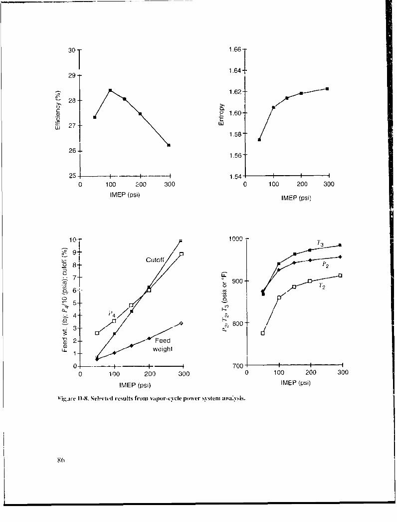
30 T 1.661
1.6429--
2. 281.62}-
02
.• 28--
A)- o0 1.60--
27--2 wU
1.586
26 11."
25 -.t --- 1.54 i A0 100 200 300 0 100 200 300
IMEP (psi) IMEP (psi)
10 / 1000 -
4::} Cutofl
7 900 -I
S4-- t4/F
• - Feed• • weight
0-I 700 III
0 100 200 300 0 100 200 300
IMEP (psi) IMEP (psi)
l'igAre I)-S. SeI-ctlid results from vapor-cycle power systemn an:iysis.
80
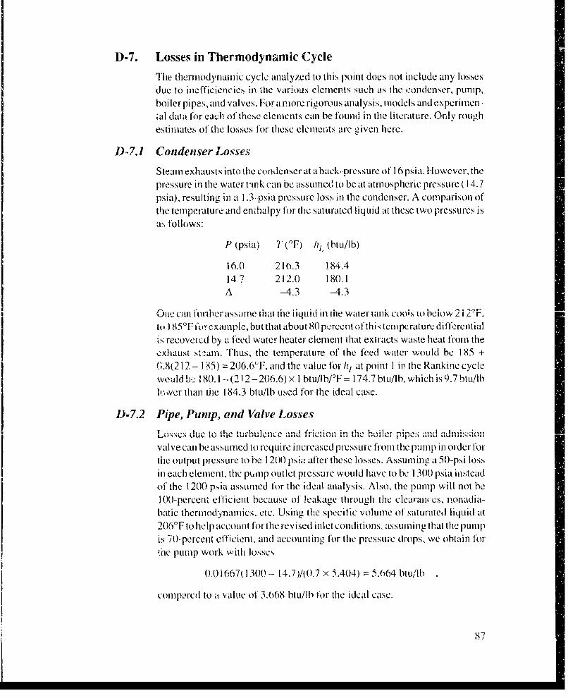
D-7. Losses in Thermodynamic Cycle
The thermodynamic cycle analyzed to this point does not include any lossesdue to inefficiencies in tie various elements such as thc condenser, pump,boiler pipes, and valves. Fora more rigorous analysis, models andlexperimen-,al data for each of these elements can be found in the literature. Only roughestimates of the losses for these elements are civen here.
D-7.1 Condenser Losses
Steam exhausts into the condenser at a back-pressure of 16 psia. However, thepressure in the water tin k can be assumed to be at atmospheric pressure ( 14.7
psia), resulting in a 1.3--psia pressure loss in the condenser. A comparison ofthe temperature and enthalpy for the saturated liquid at these two pressures isa, follows:
P (psia) 7'"(,F) hl (btu/lb)
16.0 2 10.3 184.414 7 212.0 180.1A -4.3 -4.3
One can furltlr assame That tile liquid in fhe water rank cools io below 2i 2`F.to ) 85TF fexample, but that about 80 percent of this temperature diftf-rentialis recovered by a feed water heater clement that extracts waste heat from theexhaust st,'2am. Thus, the temperature of the feed water would be 185 +(6.8(212 - 1 85) = 206.6°F, and the value for h/ at point I in the Rankine cyclewculd b:' 80.1 -(212-206.6) x I btu/Ilb/F = 174.7 btu/Ib, which is 9.7 btu/lblo,ver than tie 184.3 btu/Ib used for the ideal case.
D-7.2 Pipe, Pump, and Valve Losses......... due t � t un '",itt ~ . ,, ,•,,,,,, ., tia u "': u .,.. . ti ... ... can ,a.,, .,,; ....O_.,..,.. ,,1,o.th turbulen-ce anld f";ic;ion " ,f'l,, tIhe'"-,'l 'mu- "J''" "
valve can be assumed to require increased pressure from the pump in order fortil output pressure to be 1200 psia after these losses. Assuming a 50-psi lossin each element, the puMp outlet pressure would have to be 1300 psia insteadof the 1200 psia assumed for the ideal analysis. Also, the pump will not be100-percent efficient because of leakage through the clearaf:cs, nonadia-batic thermodynamics, etc. Using the specific volume of saturated liquid at206'F to help account fOr the revised inlet conditions assunling that the pumLpI1Pis 70-percent efficient, and account in~g for the pressure drops, we obtain f0r
lte pump work with losses
0.01i6741300- 14.7)/1(0.7 x 5.404) = 5.664 11Lt/lb
comnprc, to a valUC of 3.068 btuw/lb for tile ideal case.
8"7
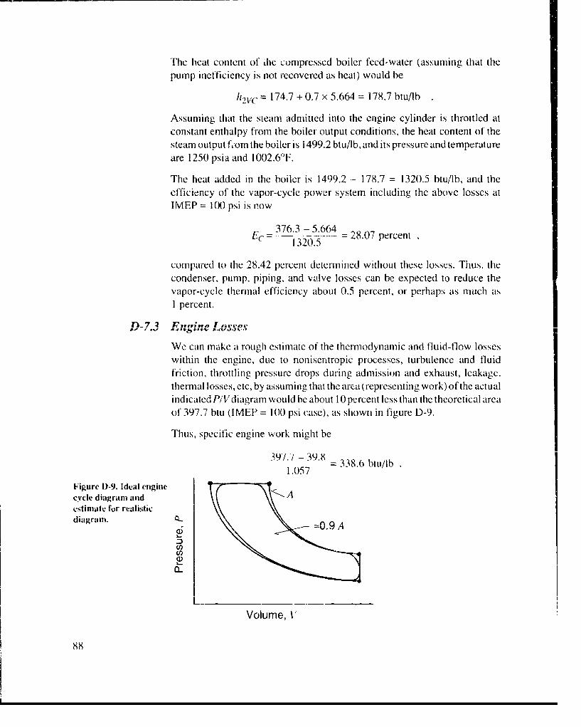
The heat content of dhc compressed boiler feed-water (assuming that thepump inefficiency is not recovered as heat) would be
"h2VC = 174.7 + 0.7 x 5.664 = 178.7 btullb
Assuming that the steam admitted into the engine cylinder is throttled atconstant enthalpy from the boiler output conditions, the heat content of thesteam output fom the boiler is 1499.2 btu/lb, and its pressure and temperatureare 1250 psia and 1002.6°F.
The heat added in the boiler is 1499.2 - 178.7 = 1320.5 btu/lb, and theefficiency of the vapor-cycle power system including the above losses atIMEP = 100 psi is now
376.3 - 5.664Ec = 1-3205 28.07 percent
compared to the 28.42 percent determined without these losses. Thus, thecondenser, pump, piping, and valve losses can be expected to reduce thevapor-cycle thermal efficiency about 0.5 percent, or perhaps as much as1 percent.
f117 :2 •lt(;1a I net-ov
We can make a rough estimate of the thermodynamic and fluid-flow losseswithin the engine, due to nonisentropic processes, turbulence and fluidfriction, throttling pressure drops during admission and exhaust, leakage.thermal losses, etc, by assuming that the area (representing work) of the actualindicated PiVdiagram would be about 10 percent less than the theoretical areaof 397.7 btu (IMEP = 100 psi case), as shown in figure D-9.
Thus, specific engine work might be
397.-/ - 39.81.057 = 338.6 btu/lb
Figure D-9. Ideal enginecycle diagram and Aestimate for realisticdiagram.
3t.-
Volume, V
88

With this estimate, the thermal efficiency of the vapor cycle, including thelosses discussed previously, is
EC 338.6-5.72521 percent
- 1320.5
So the overall efficiency reduction from the ideal is about 3 to 4 percent.
Other inefficiencies for the entire power plant, such as fuel-burner to water-heating efficiency, engine friction and accessory losses, and the inefficiencyof the motor/generator device, are discussed in the body of the report.
D-8. Conclusions and Observations
The positive-disp!acement engine-type expander is expected to be muchbetter.suitcd to low-power applications (I to 10 indicated hp, in the case of thesoldier power system) than is the turbine-type steady-flow expander [7]. Themodel shows that reasonably high efficiencies can be expected from the high-compression uniflow steam engine vapor-cycle system.
It was anticipated that the high- compression processing by the engine of someof the expanded steam back to boiler output conditions (thereby bypassing the
condensation and vaporization processes for a ,igniticant po,,ion o! theprocc:,sed steam) would result in even higher economies thini the modelpredicts. For example, for the ideai IMEP = 100 psi case, the change inenthalpy for the residual 1 lb of compressed exhaust steam would be hI..- 114
1499.2 - 1110.4 = 388.0 btu/lb (work done by the engine), versus thf-- 1 =1499.2 - 184.4 = 1314.8 btu/lb (work done by the boiler) for 1 ib of exhauststeam that is first condensed to liquid. This is an apparent savings of 1314.8
- 388.8 = 926 btu/lb for part of the steam flowing on'y through thle elngille. Inthis model at least, the 1 lb of residual steam is merely recycled through thec~jlailY, U-1li ern I LIII QIoULC)IIf.I t as nIc %vo l C.' takes. "'' -JI [I L.pr '. it .LI. I V.
vith no apparent effect on economy.
"rhc Williams Co. reportedly achieved thermal efficiency measurements inthe lab on the order of 35 perceni f(-,!- one of their engine- operating on 1000p',ia and 980°tI steam 1XJ. On the basis of this model, achieving suchefficiencics is questionable. (ilo- ever. oiher references 191 also inriicate thathigher than Rankine :hermal cll *c-iecies clan be obtwired by direct compre.-sion of exhaust vapor using a simple utarv com pressor/tnxp.m (ter hn-tvin- avery high volumetric conipression ratio: 70 : .L By opca ing at a highercompression ratio 'ýu-h a.; 33 : I, cficiency can be improved by at least I to2 percent, as shown in the cxamiple case piesclnted in ligurc D-8. This wouldput Indicated eft~ciency, witl i' ;ses, at a ievel of 27 to 28 percent at best.However, it may tm-n oui that even highcr cfficiencics are ,redictcd when themodel retincment.s discusscd in section D-9 arc investicatAd.
89)

There may be exhaust conditions, such ats higher entropy values, existing inthe residual exhaust steami of' an actual operating engine, that result in
wompression temperatures that exceed boiler temperature at the 1 200-psiarelief valve setting. Another possibility is to set the r-elict' valve pressure at itlevel niigher than boiler pressure in order- to insure compression temlperatureshigher than boiler temiperatuLre. Also, t -or a compression ratio that is highenough to always blow off part of the comipre-ssed steamn through the reliefvalve (whatever the pressure setting) and back 'into the feed-steamn manifold,
so that only p)art of the compressed steam is used each expansion cycle, someot' the economly expected From bypassing the condenser process might berealiz~ed.
Even if high compression pressures cannot improve thermnal etficiency to the30-)CrICel't level !'Or thle overall vapor cycle with losses. they do result in thlehighest ievel ý_if eng-ine efficienicy, compared to noneompression uniflowengine sys;tems,-- I KJ. This is because the cylinder and pistonl heating resultingtromn the high compre-ssion temnperature completely eliminates any condensa-tion or signi iicaiit cooling, of the incomling steamn.
D-9. Recommendations
Refinemnts 'I he va" powcr systun-n and steamn en-i' tid-, sA1houldpro ceed per. the b~llOwing" guidance. *
*Stail with a fixed e:3ginc size (cylinder volume) and specify variou0 .percent-ages ofcuttott.
*Accommnodate a variablu. weight for the steamn being compressed and for theweight remaining alter blowoff to be mixed during admission.
*inc:rease compression ratio to 33 :1 or 35:
roid a'VU prssr j rLcLI~ic"i iVi vctv fIiwtioLII Ii the~ UUlinde 1Ld fII VenI*I1
compressed steamn to the admission manifold Whenever thle preset Pressure isexceeded in the compression process.
* Calculate IME1P produced( by each specified value of cutot and pick operat-ing Values of IMFEP from thle gralph of these results.
* Develop a model using, automated -,team tables to determine properties atvarious points in the c:ycles. Evaluate performance at feed -steamn pressurc andtenlipcrature conditions of 1 500) psi and 1 200'F tor comparison with baseline
condi'tions.
*1 fri I that tlhcsc' nlV' and (I.YmIV'(Iied c y 'riumn1.% Ivouu i Iniak ideal i)Iujcc.JI' c 'ftliginceringi ,alldnh't. mnaji n
in Meii dim iphlflL a/ tho~ /nod VamII(II..
90)
" Develop detailed loss mechanisms for each phase of the engine cycle so as topredict actual indicated effective pressure instead of ideal IMEP.
" Consider alternative admission and exhaust processes that do not necessarilysupport a common entropy line to define engine operation.
" Devclop or adapt detailed models, based on material available in the engineer-ing literature, for all the elements of the vapor-cycle system (boiler, piping,condenser, feed pump, valves, etc).
91

References1. N. Hall and W. Tbele, Engineeritng Thermodynatm.us, Prentice Iltii (1960), pp
481-483.
2. G. Van Wylen, Thermodynamics, John Wiley & Sons (1959), pp 103-104,285-287.
, C. C. Williams, Steam Engine, U.S. Patents 2,102,699 (25 Julie 1946) and2,943,608 (5 July 1960).
4. J. ff. Keenan and F. G. Keyes, ThermodYnaamic Properties of Steam, JohnWiley & Sons (1936).
5. W. Barnard, F. Ellenwood, and C. I-lirshfeld, Heat-Power Engineerinm, PartI, John Wiley & Sons, Third Edition (1926), pp 315-316.
6. J. Jones and G. Hawkins, Engineering Thermodyniameic's, John Wiley & Sons,Inc. (1960), p 51.
7. V. Barnard, F. Ellenwood, and C. Hirshfeld, Heat-Power Engineeritp~, Part11, John Wiley & Somni, Third Edition (1926¢), pp 90--91.
t~. ' ,. ''V¥ IS, U'• U U t~lL f.g I)U( A. IVldLIkII~'. l J. 2~lII 1Vld4Ac1_t II~k. •.•. . D AIL Ig , I.I
9. J. Glen and T'. Edwards, Heat Engine, Refrigeration and tHeat Pump CyclesAppr(A.iariating the Carnor Cyvle and Apparatus Therefor, U.S. Patent5,027,602 (2 July 1991).
10. 0. I-artman, Schmidt Steam Enine More Effic'i'n Than Largest Turbine',Power Magazine (7 February 1922), 217-2!9.
92
DiV'ribution
Admini:3trator CommnanderDefense Technical Information Center US Army Materiel CommandAttn: DTLC-DDA (2 copies) Attn: Tech LibraryCameron Station, Building 5 5001 Eisenhower AveAlexandria, VA 22304-6145 Alexandria, VA 221333-0001
Defense Advanced Research Projects Agency US Army Research OfficeAttn: ASTO, R. Murphy Attn: SLCRO-D, J. lafrateAttn: LSO, J. Richardson Attn: SLCRO-GSD, R. Singleton3701 No. Fairfax Dr. Attn: SLCRO-PiI, J. KrugerArlington, VA 22203-1714 Durham, NC 27709-2211
Oftfice oi the Assistant Secretary of the Army Commainderfor Research, Development & Acquisition US Army Tank-Au~tomotive Command
Attn. SARD-TR, K. Gabriel Attn: Tech LibraryAttn: SARD-TT, F. Milton WreM'13750Attn: SAR.D-TT, S. VannucciWarnMI43750Washington, DC 203 10-0 100 US Army Troop Support Command NRDEC
US Army ARDEC Attn: STRNC-TTrE, C. Fitzgerald
Attn~: SMICAR-CCj, V. Shiiidc Attn: STRNC-TTF, P. SnowAttn: SIRNC- IA, R. Kinney
Picatinny Arsenal, NJ 07806-5000 Attn: STRNC--ICA, W. Goodwin
US Army lBelvoir RDE Center Attn: STRNC-,CA, G, lProulxAtin: STRBE-F (IPS), L. Amistutz Attn: STRNC-ICAS, H. DanzigerAttn: STRI3E-F (IPS), M. Miller Attn: STRNC-Tech LibraryAttn: STRBE-F (IPS), R. Ware Natick, MA 0 1760-5002Attni: STRBE-FED, N. BlackwvellAttn: STRBE-FGE. J. Ferrick Conimanding OfficerAttn: STRBE-H-P, M. Sparks US Foreign Science & Technology Center
F-l7 -:1-,~ 11 A 1,?Ar J( A A in A I AVT -Q R- 1ZI )IV(,U k V tIZ V k . .'- -T e -- -i~V
US Armyv Hunian Enoineci ing Laboratory Feea fieB IldnAnn:SLCH-D, . CoonaCharlottesville, VA 22901
Abecrdeeni Proving Ground, MD 21005f-5006 Naval Research LaboratoryAttni: Code 4820, Technical Info Div
Commander 4.555 Overlook Ave-. SWUS Army lnfantr'- School Washi1ngton. DC 20375-5000Attn: ATSII-TS, D. AndersonFt Benning,. GA 31905 Coniiander
US Ariý JFSWCSNaval Surl'icc WarfareL CenterUS Ary JFSWCSAttn. E3-43, Technical Library
Attn-. AOiK-CD-CS. S. RarinenmWie a.NID291FI T hagg, NC 28307-5000
93
Distribution (conit'j)
Commander Carnegie MellIon UniversityNaval Surfatce Warfare Center Attn: R. AyresAttn: DX-21I Library Div Dept. of Engineering & Public PolicyDahilgrcn, VA 221448 P~ittsburgh, PA 15213-3890
Engineering Societies Library Clarkson UniversityAttri: Acquisitions Department Attn: Dept. of Mech. Engineering345 East 47th St. Potsdam, NY 13676-1499New York, NY 100 17 Georgia Institute of Techntology
USSOCOM Attn: Dept. of Mech. Engineering
Attn: SOSD-MT, D. Bennett Atlanta, GA 30332
Bldg. 501 North Carolina State UniversityMcDilI AFB, Fl- 33608-6001 Attn: Dept. of Mech. Engineering
Raleigh, NC 27695Department of Energy Pennsylvania State UniversityAibu~querqueC Operations Office Attn: Dept. of Mech. EngineeringAttn: PO Box 5400UnvriyPkA160Albuquerque, NM 87115UnvriyPkA162
Law; ence Livermore National Laboratory Princeton UniversityAttn: Technical Info Dept Library Attn: Dept. of Meeh. Engineering
PO Box 808 1kL6ctn NjOS5.10
Livermore, CA 94550 Rutgers University
Sandia National Laboratories Ptin Detawy NJMeh 08854 eii
Attn: Technical Library PsaaaN 85
PO Box 5800 Stanfo~rd UniversityAlbuq~uerque, NIM 87 185 Attn: Dept. of Meccl. Engineering
Director NASA Stanford, CA 94305
Attn: Technical Library Universityv of IllinoisLlcwis I\...'.sc1ILI C..lLLI Ann:h LJLiL. of IMICLII1-. Lh191iicullhhhI
Cleveland, OH 44135 Chicago, IL 0068(0
NASA Sci & Tech Info Facility University of MarylandAttn: Technical Lihbrary Attn: Dept. of'Mechi. Engineering6571 E'lkri-dge Landing Rd College Park, MI) 20742Lin1thiCurni Hgts, MD 21I090 Univi~ersity' of Michigan
DireiorAttn: Dept. of Mecli. lngincering
National Institute of Standards & Techlmology Ann Arbor. MI 48107
Attn: LibraryWashington, DC 20234
94
Distribution (cont'd)
University of Utah Stirling Technology Co.Attn: Dept. of Mech. Engineering Attn: C. BeckettSalt Lake City. UT 84112 2952 George Washington Way
University of Virginia Richland, WA 99352
Attn: Dept. of Mech, Engineering US Army Laboratory CommandCharlottsville, VA 22906-9017 Attn: AMSLC-.AT, R. Childress
University of Wisconsin Attn: AMSLC-CGAttn Dep. ofMec. EnineeingAttn: AMSLC-I)L, R. Vitali
Maditn, Dept ofMe.Eninern Atm: AMSL.C-TP-', 13. FonoroffMadionWI 506Attn: AMISL.C-TP-P, J1. Prcdhamn
Virginia Polytechnic Institute and State Attn: AMSL-C-TP-P, P. JohnsonUniversity Attn: AMSLC-TP-PB, J. Gaul
Attn: Dept. of Mech. 1En-rgineering Attn: AMSL~c-TP-P1B, M, SwannBlacksburg, VA 24061 Attn: AMSL-C-TP-STr, S. Karmichelty
Wayne State University Installation Support ActivityAttn: Dept. of Mech. Engineeringr Attn: SLCIS-CC-1P", Legal OfficeDetroit, MI 48202-3489 USAISC
ProgrmMaagerAttn: AMSLC-IM-VA, Adniin Ser Br
Clothing and Individual Equipment Attn: AMSLC-IM-VP, Tech Pub Br (2 copies)
Attn: PM-CIE. R. Grube [larry Diamond Laboratories14-050 Dawson Beach Rd. Attn: SLCHD-CS, J. SattlerWoodbridge, VA 22 191-1419 Attn: SL-CHD-DD, J. Scully
Electronics Development Corporation Attn: SLCHD-ES-ET, G3. Smith
Attn: R. Johnson Attn: SLCHD-ES-MT, 3. Spellman ;Attn: SLCHD-ES-NT, A. Frydnian
9055F Guilford RoadAt:SLI-EPT(.Lcy
ColubiaWI~ - I'd)Attn: SLCIID--NW, Director
Mass. Institute of Technology Attn: SLCIID-NW-RZF, E. ScannellAtti: Dept. of Mech. Engineering Attn: SLCI-ID-SD-P. 1i. ColeCambridg-e, MA 02139 Attn: SLCI-ID-TA, E. R. Sebol
Attn: SLCHD-TA, J. EvansMechanical Technology Inc. Attn: SLCIID-TA, P. F. IngersollPower Systems Div Attni: S LCHL)-TA-AS, P. EmnmermianAttn: B. Goldwater Attn: SLCHD-TA-EN', J. Nelson968 Albany-Shaker Rd. Attn: SL-CIiD-TA--ES, R. GoodmanLatham, NY 121110 Attn: S LCHD-TA-l-D, C. Campagnulo1
Resources for the Future, Inc. (10: Scpies) MS . vrna
Attn: Tech Library Atm 1 LC coiDe AMs.)iiniu
1755 Mass. Ave. Ai:SCl-AM.G iicoi
Washington, DC 20036 Attn: SLCIID-TA-NIS, J. Reard
95
Distribution (cont'd)
Harry Diamond Laboratories (cont'd) Harry Diamond Laboratories (cont1d)Attn: SLCHD-TA-MS, J. Ilartranft Attn: SLCHD-TL, LibraryAttn: SLCHD-TA-MS, S. Tenney Attn: SLCCHD-TL, Library (Woodbridgc)Attn: SLCHD-TA-SS, R. Christopherson Atn: SLCHD-TS, W. WebsterAnn: SLCHID-TA-TS, J. Eike Attn: SLCHD-D, J. Reed
96