Agricultural Pumping Efficiency Programcwi.csufresno.edu/pumpefficiency/About/literature/Water...
16
Water Wells and Energy Agricultural Pumping Efficiency Program Helping California Agriculture...
Transcript of Agricultural Pumping Efficiency Programcwi.csufresno.edu/pumpefficiency/About/literature/Water...

Water Wells and Energy
Agricultural PumpingEfficiency Program
Helping California Agriculture...

The Agricultural Pumping Efficiency Program (“Program”) has two overall objectives: 1) to get high-efficiency pumping equipment in the field and 2) to manage that equipment so that its potential efficiency is realized. Understanding the factors involved in specifying, monitoring, and maintaining efficient water wells is an important part of good overall management practices and can save you energy dollars.
What is the Program?
The Agricultural Pumping Efficiency Program is an educational and incentive program designed to improve water pumping efficiency and promote energy conservation in agriculture. This program is also available to:
• Utility customers with large turf operations such as golf courses, parks, and schools.
• Municipal and private water company potable and tertiary - treated water-pumping plants.
The Program includes these key components:
• Subsidized pump efficiency tests
• Incentive rebates for pump retrofit or repair
• Education
The educational message has four parts:
1. Know how to specify an efficient pump
2. Know how to maintain an efficient pump
3. Know how much water has to be pumped
4. Know how much water has been pumped
This brochure addresses the water well. Water wells affect the first and second educational messages, “know how to specify an efficient pump” and “know how to maintain an efficient pump.” Simply put, it takes more energy to lift water from deeper levels.
Correct well design and construction is an essential factor that influences how much lift is required. Routine pump testing and monitoring water well performance can determine whether modifications to the pump and water well can reduce energy costs.
2
Water Wellsand Energy
3
This brochure describes design, construction, and maintenance of water wells. Each of these aspects is linked together. For example, it is possible to have an energy efficient well (minimal drawdown), but if the sand output is high the energy efficiency will be lost through rapid wear of the pump components. Striking a balance between high efficiency and ensuring long term clean water input into the well is an important consideration in well design and construction.
Water well performance affects how much it costs to pump an acre-foot of water. This relationship is shown by the equation used to calculate the dollars needed to pump an acre-foot of water through a system.
The equation below is for a single pump in a water well, powered by electricity. Most of the concepts apply to other fuel sources and pumping situations.
1.0241 = constant
TDH = total dynamic head developed by the system in feet of water head OPE = overall pumping plant efficiency expressed as a decimal (i.e 50% OPE would be seen as .5 in the equation)
Example: The equation indicates that you can reduce the cost per acre-foot pumped by lowering the unit energy cost, reducing the total dynamic head, and/or improving the pumping plant efficiency. The water well’s role as a component of total head contributes to the cost of pumping water.
The total dynamic head (TDH) has many compo-nents: 1) the pumping water level addressed in this brochure); 2) the pressure requirement for the water system itself; and 3) any friction losses or elevation
Introduction
The Relationship Between the Water Well, the Pump, and the Cost to Pump Water
$ per kWh x 1.0241 x TDHOPE
Average cost per acre-foot pumped
=
$ per kWh = average cost of energy used by the pumping systemWhere:
4
changes not accounted for in the water system’s require-ments.
Note: An improvement in the water well performance will not give energy savings if it does not reduce the total head and increase the flow rate into the system.
If the pumping water level is raised and results in added pressure above ground, but no additional flow rate, then there is no energy savings from a water well treatment. The amount of work done by the pump, and the amount of energy consumed, is identical because there has been no change in the total head developed by the pump. However, the added pressure may improve irrigation system uniformity and result in a decrease of pump operating hours.
Pump efficiency can also be affected by changes in the water well. Suppose a new pump for a furrow irrigation system is designed to produce 1,000 gallons per minute at 200 feet of lift with an overall pumping plant efficiency of 65%. However, due to changes in well output, the pump is now producing 800 gallons per minute at 240 feet of lift with an overall pumping plant efficiency of 50%. Not only has the lift increased, but the pump no longer operates at its best efficiency point. Restoration of this water well would bring the pump back to its original, best efficiency point, and also decrease the total head. Note again the ratio in the equation (page 3): the cost per acre-foot of water is directly related to the ratio of total head divided by the OPE.
IMPORTANT!Information contained in this brochure is for educational purposes only. Always consult a water well expert for specific recommendations. Please contact the Program if you have specific questions.
5
Definition of Concepts and Terms
This brochure introduces some concepts and terms (italicized in the text) that can help you specify and maintain an efficient water well. Among these concepts are:
Aquifer – an underground water-bearing strata, composed of porous materials such as sand and gravel capable of giving up usable amounts of water.
Cascading water – water that enters the well above the pumping water level and may cause air entrainment and reduced pump output.
Drawdown – the difference between the pumping water level and the standing water level.
E-log – an electronic logging technique used during drilling that helps determine the type of materials penetrated and degree of water salinity at various depths.
Gravel pack – the interface or filter between the aquifer material and well screen.
Overall pumping plant efficiency (OPE) – the power output of the pump (water flow rate and total head) divided by the input power.
Pumping water level – the stabilized water level in the well under constant pumping.
Standing water level – the water level in a water well when a pump has not been running.
Water well development – the process of removing the materials created from the boring process and maxi-mizing well efficiency.
Water well efficiency – a ratio between the drawdown in the aquifer and the drawdown inside the well casing.
Water well rehabilitation – the process of restoring water well specific capacity using a variety of chemical and physical techniques.
Well casing – the solid piped portion of the well typically constructed of steel or PVC.
Well screen – the perforated area of the well casing that allows water to enter the well.
Well specific capacity – a description of the well’s output expressed as gallons per minute per foot of drawdown (gpm/ft).
6
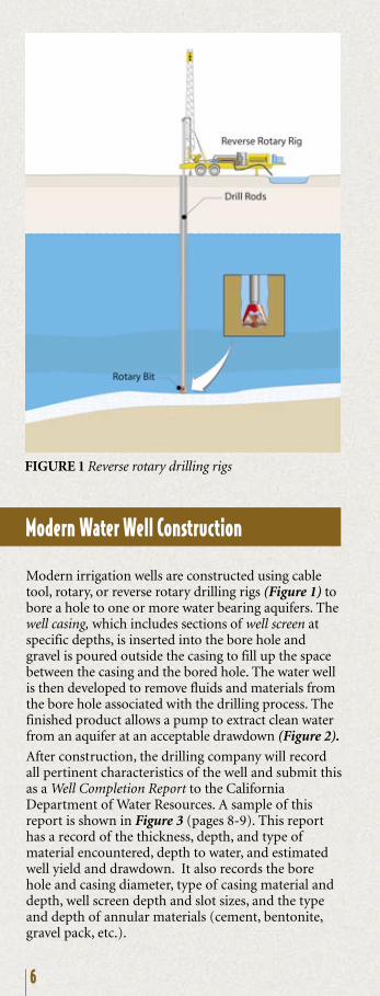
Modern irrigation wells are constructed using cable tool, rotary, or reverse rotary drilling rigs (Figure 1) to bore a hole to one or more water bearing aquifers. The well casing, which includes sections of well screen at specific depths, is inserted into the bore hole and gravel is poured outside the casing to fill up the space between the casing and the bored hole. The water well is then developed to remove fluids and materials from the bore hole associated with the drilling process. The finished product allows a pump to extract clean water from an aquifer at an acceptable drawdown (Figure 2).
After construction, the drilling company will record all pertinent characteristics of the well and submit this as a Well Completion Report to the California Department of Water Resources. A sample of this report is shown in Figure 3 (pages 8-9). This report has a record of the thickness, depth, and type of material encountered, depth to water, and estimated well yield and drawdown. It also records the bore hole and casing diameter, type of casing material and depth, well screen depth and slot sizes, and the type and depth of annular materials (cement, bentonite, gravel pack, etc.).
Modern Water Well Construction
FIGURE 1 Reverse rotary drilling rigs
6
Modern irrigation wells are constructed using cable tool, rotary, or reverse rotary drilling rigs (Figure 1) to bore a hole to one or more water bearing aquifers. The well casing, which includes sections of well screen at specific depths, is inserted into the bore hole and gravel is poured outside the casing to fill up the space between the casing and the bored hole. The water well is then developed to remove fluids and materials from the bore hole associated with the drilling process. The finished product allows a pump to extract clean water from an aquifer at an acceptable drawdown (Figure 2).
After construction, the drilling company will record all pertinent characteristics of the well and submit this as a Well Completion Report to the California Department of Water Resources. A sample of this report is shown in Figure 3 (pages 8-9). This report has a record of the thickness, depth, and type of material encountered, depth to water, and estimated well yield and drawdown. It also records the bore hole and casing diameter, type of casing material and depth, well screen depth and slot sizes, and the type and depth of annular materials (cement, bentonite, gravel pack, etc.).
Modern Water Well Construction
FIGURE 1 Reverse rotary drilling rigs
7
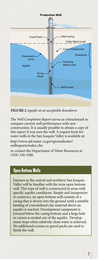
FIGURE 2 Aquifer at an acceptable drawdown
Production Well
DownwardCurve
Gravel Pack
Aquifer
PumpBowls
Well Casing
Static Water Level
PumpingWater Level
Cone of Depression
Well Screen
Drawdown
The Well Completion Report serves as a benchmark to compare current well performance with new construction. It is usually possible to obtain a copy of this report if you own the well. A request form for water wells in the San Joaquin Valley is available at:
http://www.sjd.water. ca.gov/groundwater/wellreports/index.cfm
or contact the Department of Water Resources at(559) 230-3300.
Farmers in the central and northern San Joaquin Valley will be familiar with the term open bottom well. This type of well is constructed in areas with specific aquifer conditions. Simple and inexpensive to construct, an open bottom well consists of a casing that is driven into the ground until a suitable landing of consolidated clay material above an aquifer is reached. Development equipment is lowered below the casing bottom and a large hole or cavern is eroded out of the aquifer. Develop-ment stops when relatively clean water is achieved. No additional screens or gravel packs are used to finish the well.
Open Bottom Wells

FIGURE 3 Example well completion report
98

FIGURE 3 Example well completion report
98
10
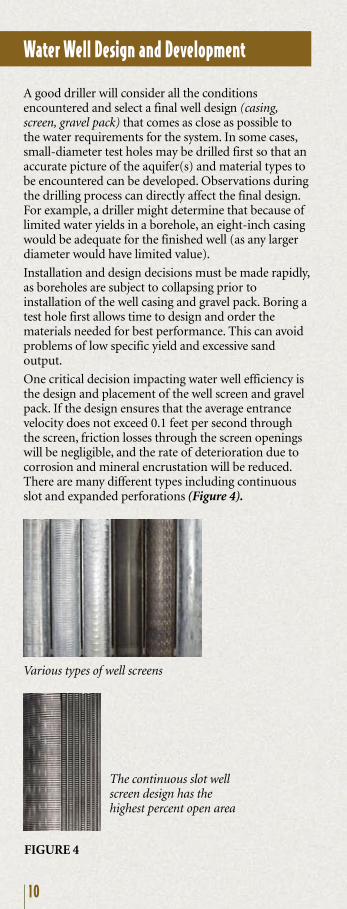
Various types of well screens
Water Well Design and Development
A good driller will consider all the conditions encountered and select a final well design (casing, screen, gravel pack) that comes as close as possible to the water requirements for the system. In some cases, small-diameter test holes may be drilled first so that an accurate picture of the aquifer(s) and material types to be encountered can be developed. Observations during the drilling process can directly affect the final design. For example, a driller might determine that because of limited water yields in a borehole, an eight-inch casing would be adequate for the finished well (as any larger diameter would have limited value).
Installation and design decisions must be made rapidly, as boreholes are subject to collapsing prior to installation of the well casing and gravel pack. Boring a test hole first allows time to design and order the materials needed for best performance. This can avoid problems of low specific yield and excessive sand output.
One critical decision impacting water well efficiency is the design and placement of the well screen and gravel pack. If the design ensures that the average entrance velocity does not exceed 0.1 feet per second through the screen, friction losses through the screen openings will be negligible, and the rate of deterioration due to corrosion and mineral encrustation will be reduced. There are many different types including continuous slot and expanded perforations (Figure 4).
FIGURE 4
The continuous slot well screen design has the highest percent open area
Casing and screen slot may be plastic or steel. Different types of steel may be called for in different water quality conditions. The size of the screen opening and the number of openings (total open area) per foot of casing are also important decisions.
In many cases, an E-log is taken as the raw well bore is completed. This will indicate to the well designers at what depths aquifers are located and what quality of water might be expected. Gravel pack, well casing and well screen can be designed to prevent poor quality water from entering the well. Likewise, cascading water can also be prevented by locating well screens below pumping water levels.
Water well development is achieved by a process of surging, jetting, and/or overpumping. Development is needed to correct any damage done to the formation during the drilling process, to remove any fine materials that retard water flow, and to stabilize the aquifer and gravel pack material.
The finished water well has a specific capacity which is defined as the amount of water obtained per foot of drawdown. It is important to note that specific capacity usually varies depending on the amount of water pumped. Monitoring for changes in specific capacity is a key to keeping energy bills low.
The gravel pack functions as a support layer and filter for the surrounding aquifer. When properly sized and installed, it can control sand production and permit larger screen openings. Gravel pack thickness ranges from three to nine inches (Figure 5).
11
FIGURE 5 Gravel pack behind the well screen

12
Well Deterioration and Rehabilitation
IMPORTANT!Well treatments require trained professionals using the proper methods acting in accordance with local, state, and federal regulations. No specific recommendations are given in the following section.
Water well performance deteriorates with time, due to clogging, corrosion, or changes in the aquifer condition. The following guideline can be used for evaluating an existing well:
1) Look at the historical performance of the well. Use a well completion report and pump tests covering a several-year period. Compare standing and pumping water levels, specific capacity changes, and pump flow rate fluctuations.
2) Evaluate the performance of another well in the area. If a well appears to be abnormal, local well drillers and pump dealers can indicate that there is a problem. Data from adjoining wells can be used to determine whether well specific capacity issues are primarily an aquifer condition, or a well casing, development, and gravel pack issue. For example, assume another well pumping 1/4 of a mile away greatly influences your well yield. This probably indicates an aquifer limitation. Conversely, if a neighboring well seems to have no affect, a well screen or gravel pack issue is indicated.
3) Inspect the well. Sand, silt, and gravel pack materials in pumped water usually indicate a problem with the well casing and/or screen. Early detection of these materials in a pump’s output can make the difference between a possible repair or an expensive new well. Video photography of a well can help reveal problems of corrosion, mineralization, bacterial clogging, sand sloughing, and erosion of screen slots.
Well clogging can be due to mechanical, chemical or biological factors. Clogging can occur in the aquifer itself, the gravel pack, and the screen slots.
As a general rule, treatment should be done when the specific capacity (gpm per foot of drawdown) of a well is reduced by 10-30% and it has been determined that this is not related to a decline in the aquifer or interference from surrounding wells. A reduction in specific capacity should not be confused with a reduction in flow output from the pump, even though the two may be related.
13
To illustrate, a new water well has a specific capacity of 50 gpm per foot of drawdown. Two years later, a pump test is done at the same time of year and a similar standing water level. It is found that the specific capacity has dropped to 35 gpm per foot of drawdown. The percent change is 15 gpm, which is about a 30% reduction in capacity. Treatment should be considered.
Mechanical clogging is caused by migration of fine particles toward the screen. This movement may be caused or encouraged by frequent pump cycling, improper well design, inadequate development, and overpumping (exceeding the design flow rate for the well). As the particles move and converge at the screen vicinity, they restrict water flow from the aquifer.
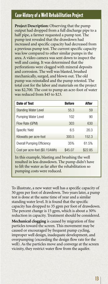
Project Description: Observing that the pump output had dropped from a full discharge pipe to a half pipe, a farmer requested a pump test. The pump test revealed that the drawdown had increased and specific capacity had decreased from a previous pump test. The current specific capacity was low compared to other similar pumps in the area. A video camera was sent down to inspect the well and casing. It was determined that the perforations were clogged with mineral deposits and corrosion. The well was blasted, brushed mechanically, surged, and blown out. The old pump was reinstalled and the pump retested. The total cost for the labor and materials on the project was $2,700. The cost to pump an acre-foot of water was reduced from $45 to $23.
Case History of a Well Rehabilitation Project
In this example, blasting and brushing the well resulted in less drawdown. The pump didn’t have to lift the water as far after the rehabilitation so pumping costs were reduced.
Date of Test Before After
Standing Water Level 55.3 59
Pumping Water Level 102 90
Flow Rate (GPM) 303 630
Specific Yield 6.5 20.3
Kilowatts per acre-foot 300.5 152.3
Overall Pumping Efficiency 35% 61.5%
Cost per acre-foot ($0.15/kWh) $45.07 $22.85

14
Solution: Thorough development of the aquifer surrounding the well screen can largely correct clogging from fine particle movement.
However, with some sandstone and limestone aquifers, breakdown of the cementing material can occur with time. This type of clogging problem is usually difficult to resolve because of the distance between the clogging material and the well casing. A soap-type product such as a polyphosphate or a surfactant may be used to help disperse the particles. Agitation and surging are then applied to penetrate the aquifer, followed by pumping to clean out the well.
Chemical clogging or incrustation is also a common problem in water wells. Screen, gravel pack, and aquifer material can all become clogged from precipitation of minerals, iron, and manganese. Because pumping a well moves water out of an aquifer and into the well, a reduction in pressure occurs. Any gases in the water may be released, similar to what happens to a carbonated beverage when the seal is broken. The water is then unable to maintain the same level of mineral saturation, leading to deposition (Figure 6).
FIGURE 6 Incrustation
Solution: In the planning phase, well screens should be designed to have adequate open area for the required system flow rate. The greater the open area, the slower the water velocity and the lower the rate of mineral deposition. A reduction in pump capacity can also reduce mineral deposition. For existing water wells that have already experienced chemical clogging, strong acidification and agitation are required.
Biological clogging due to bacteria can occur when there is iron or manganese present in the water. Iron bacteria produce slimes and precipitates that can rapidly clog openings in the well screen, gravel pack, and pores in the aquifer (Figure 7). The degree of activity depends on many factors and will vary from well to well.

15
Solution: Chemical treatment with chlorine is the most widely used method, sometimes enhanced by acid treatment at the same time. Chemical treatment needs to be accompanied by agitation or jetting so that there is good penetration into the gravel pack and aquifer.
Corrosion is the process steel goes through when it reverts back to its original, stable mineral condition of iron ore. Corrosion can enlarge or block screen slots and weaken well materials, leading to sand pumping and eventual failure of the well.
Solution: Corrosion can be minimized by the selection of casing and screen material appropriate for the groundwater conditions, and keeping the water velocity low through the screen slots.
FIGURE 7 Biological clogging
Summary
Design, construction, and maintenance of water wells has a direct effect on how much it costs you to pump water. Careful record keeping will help pinpoint actions that keep water wells efficient.
Monitoring pump efficiency and making sure that the well and the pump are continually operating as designed will help your equipment operate as efficiently as possible.
The Program may be able to provide rebates for pump repair and well rehabilitation projects. Please log on to www.pumpefficiency.org or call (800) 845-6038 for more information.

The Center for Irrigation Technology (CIT) developed and manages the Agricultural Pumping Efficiency Program. CIT is dedicated to advancing water and energy management practices and efficient irrigation technology. Located on the campus of California State University, Fresno, CIT functions as an independent testing laboratory, applied research facility and educational resource to both the public and private sectors. For more information, check the CIT link at www.pumpefficiency.org or call(800) 845-6038 or (559) 278-2066.
The Center for Irrigation Technology
The Program may be terminated or modified without notice. The Program has a limited budget. Applications for retrofit/repair rebates or pump tests are accepted on a first-come, first-served basis until available funds are allocated or the ending date of the program, whichever comes first (visit www.pumpefficiency.org or call(800) 845-6038 for more information).
California consumers are not obligated to purchase any full fee service or other service not funded by this program. This program is funded by California utility ratepayers under the auspices of the California Public Utilities Commission.
Los consumidores en California no estan obligados a comprar servicios completos o adicionales que no esten cubiertos bajo este programa. Este programa esta financiado por los usuarios de servicios públicos en California bajo la jurisdiccion de la Comisión de servicios Públicos de California.
Important!
APEP-23 11-05
Development and management of theAgricultural Pumping Efficiency Program by:
The Center for Irrigation Technology California State University, Fresno 5370 North Chestnut Ave. – M/S OF 18 Fresno, CA 93740-8021 (559) 278-2066