AGRICULTURAL MACHINES FUNCTIONAL AND … MACHINES FUNCTIONAL AND SAFETY TESTING SERVICE ... brake...
12
AGRICULTURAL MACHINES FUNCTIONAL AND SAFETY TESTING SERVICE ENTAM TEST REPORT No. 05.104a AIR-ASSISTED FIELD SPRAYER: IBIS 2500 - ALA UNI 21 (extensions: 05-104b – IBIS 2500 – ALA UNI 18; 05-104c – IBIS 2500 – ALA UNI 24; 05-104d – IBIS 2000 – ALA UNI 16; 05-104e – IBIS 2000 – ALA UNI 18; 05-104f – IBIS 2000 – ALA UNI 21) MANUFACTURER: UNIGREEN S.P.A. Via Rinaldi, 105 – 40200 REGGIO EMILIA Rome, November 2002 This report has been made by ENAMA under its responsibility
Transcript of AGRICULTURAL MACHINES FUNCTIONAL AND … MACHINES FUNCTIONAL AND SAFETY TESTING SERVICE ... brake...

AGRICULTURAL MACHINES FUNCTIONAL AND SAFETY TESTING SERVICE
ENTAM TEST REPORT No. 05.104a
AIR-ASSISTED FIELD SPRAYER: IBIS 2500 - ALA UNI 21 (extensions: 05-104b – IBIS 2500 – ALA UNI 18; 05-104c – IBIS 2500 – ALA UNI 24;
05-104d – IBIS 2000 – ALA UNI 16; 05-104e – IBIS 2000 – ALA UNI 18;
05-104f – IBIS 2000 – ALA UNI 21)
MANUFACTURER: UNIGREEN S.P.A. Via Rinaldi, 105 – 40200 REGGIO EMILIA
Rome, November 2002
This report has been made by ENAMA under its responsibility

Unigreen – IBIS 2500
2/12
TESTS CARRIED OUT IN COMPLIANCE WITH ENTAM SPECIFICATIONS NO 2: TECHNICAL
INSTRUCTIONS FOR ENTAM – TESTS OF FIELD CROP SPRAYERS BY THE MECHANICS
SECTION OF THE DEPARTMENT OF AGRICULTURAL, FOREST AND ENVIRONMENTAL
ECONOMICS AND ENGINEERING, UNIVERSITY OF TURIN: Supervisor: Prof. Paolo Balsari Data collector: Dr. Mario Tamagnone
TABLE OF CONTENTS TECHNICAL DATA 3 SIZE AND WEIGHT 3
MAIN TANK 3 AUXILIARY TANKS 3 INTRODUCTION BOWL 4 CLEANING OF COMMERCIAL PRODUCT CONTAINERS 4 PUMP 4 FILTERS 4 FLOW RATE ADJUSTMENT 5 MONITORING OF DISPENSING 5 PRESSURE ADJUSTMENT 5 FLOW ADJUSTMENT 5 SET-UP OF DISPENSING SYSTEM 5 BOOM 5 FAN 6 NOZZLES 6
DESCRIPTION OF MACHINE 6 RESULTS 7
MAIN TANK 7 FLOW RATE ADJUSTMENT 8 CONTROL INSTRUMENTS 8 PRESSURE DROP 9 ANTIDRIP DEVICE 9 NOZZLE FLOW RATE 9 REGULARITY OF TRANSVERSAL DISTRIBUTION 10 FAN 10 TOTAL RESIDUE 10
NOTES ON FUNCTIONALITY 10 RECOMMENDED CONDITIONS OF USE 11 TESTING OF SAFETY REQUIREMENTS 11
To facilitate interpretation of the results, it should be remembered that:
1 MPa = 10 bar 1 kW = 1.36 CV 1 m3/s = 3,600 m3/h 1 m/s = 3.6 km/h 1 l = 1 dm3 C.V. (coefficient of variation) = parameter indicating the extent of data deviation from mean value.

Unigreen – IBIS 2500
3/12
Technical data
engine type Perkins 1004.40TW declared HP (kW) 91 transmission hydrostatic forward speed minimum (km/h) 0 - 20 maximum (km/h) 0 - 40 tyres 230/95 R44 alternatively 270/95 R44 420/85 R34 340/85 R38 brake systems hydraulic on all rear wheels suspension hydraulic on 2 axles type approval for road circulation yes
Size and weight max. total length (mm) 7330 wheelbase (mm) 3280 underbeam clearance at centre of machine (mm) 800-1005 max. transportation width (mm) 2500 max. transportation height (mm) 3750 max. total mass empty (kg) 6000 full load (kg) 8940
Main tank ID code and model 2000 (0826 03300) - 2500 (0826 02600) material fibreglass nominal capacity (l) 2000 - 2500 diameter filling hole (mm) 385 emptying system type ball valve position left side graduated contents indicator type float position right side sensitivity (l) 100 filling system auxiliary pump agitation system hydraulic
Auxiliary tanks auxiliary tank for cleaning circuit ID code and model 0826 02302 effective capacity (l) 255 auxiliary tank for operator ID code and model R902510

Unigreen – IBIS 2500
4/12
effective capacity (l) 15.2
Introduction bowl present yes position left side model top mix 40 capacity (l) 40
Cleaning of commercial product containers present yes position left side
Pump manufacturer Comet model BP 280 type piston-diaphragm maximum speed (RPM) 550 nominal flow rate (l/min) 265 max. pressure (bar) 20 hydropneumatic compensator yes
Filters filling
number 2 position filling hole type strainer mesh material nylon mesh opening (mm) 1 filtering surface (cm2) 2814 position external suction tube type cylinder mesh material stainless steel mesh opening (mm) 1 filtering surface (cm2) 320
suction position right side type cylinder mesh material stainless steel mesh opening 80 filtering surface (cm2) 400
delivery number 1 position right side type cylinder mesh material stainless steel mesh opening 100 filtering surface (cm2) 216

Unigreen– IBIS 2500
5/12
Flow rate adjustment TeeJet 844 computer, motorised TeeJet control unit, Polmac 10÷100 l/min flow meter, TeeJet motorised boom section unit, no backflow, calibrated
Monitoring of dispensing possibility of placing controls inside cab: yes possibility of working in fully closed cab yes
Pressure adjustment operation electrical position driver’s seat
Flow adjustment operation electrical position driver’s seat
Set-up of dispensing system operation hydraulic position driver’s seat control electrical
Boom base deformable trapezium height adjustment stepless
minimum (mm) 500 maximum (mm) 2000
folding hydraulic with electrical control side inclination hydraulic with electrical control oscillation hydraulic clamping – electrical control variable position hydraulic with electrical control nozzle spacing (mm) 500 diameter nozzle-holder tube (mm) 18
16 18 21 24 working width (mm) 16000 18000 21000 24000 total width (mm) 15800 17800 20800 24100 number of nozzle holders 32 36 42 48 number of nozzles 96 108 126 144
section 1 2 3 4 5 6 7 ALA UNI 16
no. nozzles 7 7 4 7 7 --- --- working width (mm) 3500 3500 2000 3500 3500 --- ---
ALA UNI 18 no. nozzles 8 8 4 8 8 --- ---
working width (mm) 4000 4000 2000 4000 4000 --- --- ALA UNI 21
Unigreen – IBIS 2500
6/12
no. nozzles 8 9 8 9 8 --- --- working width (mm) 4000 4500 4000 4500 4000 --- ---
no. nozzles 5 4 8 8 8 4 5 working width (mm) 2500 2000 4000 4000 4000 2000 2500
ALA UNI 24 no. nozzles 5 7 8 8 8 7 5
working width (mm) 2500 3500 4000 4000 4000 3500 2500
Fan number 1 type axial, fixed blades position rear axis of rotation vertical size diameter of runner (mm) 680 area of flow section 0.24/16 - 0.27/18 - 0.32/21 - 0.38/24 number of blades 14 number of speeds stepless – electrical control max. rotation speed (motor with rotation speed of 2,200 rpm) (rpm) 3600
Nozzles Antidrip device membrane mount Bayonet nozzle type flat fan, low-drift flat fan nozzle holder triple
Description of machine The machine is a self-propelled sprayer for use on ground crops. Liquid is sprayed from small-sized nozzles. Drops are conveyed by a draught of air generated by an axial fan. The machine frame is made out of painted steel; the main tank and the circuit cleaning tank are made out of fibreglass while the auxiliary tank for the operator is made out of polyethyl-ene. The main tank, having a nominal storage capacity of 2,000-2,500 l, is fitted with a content indicator located on the front left of the tank, the liquid level can be viewed using an external transparent tube connected
to a float placed inside the tank. The tank may be filled directly from an auxiliary pump using a pipe fitted to a hydraulically-controlled winder. To access the tank’s filling hole a small ladder leads up to a raised platform on the left hand side. On the left are the auxiliary tank for the operator and an introduction bowl for products, inside which is a device for cleaning empty containers. The tank for clean-ing the dispensing circuit and inner walls of the tank is located in the cab. The piston-diaphragm pump is oper-ated by a hydraulic motor. The hydraulic circuit dispenses spray mixture in proportion to the vehicle’s

Unigreen– IBIS 2500
7/12
forward speed and is electronically controlled. The machine has a sensor to determine forward speed and a flow meter to determine the boom flow rate. Using the data supplied by these sensors and by the operator via the control panel in the cab, the elec-tronic system can control the motor-ised valve that adjusts working pres-sure to keep the volume application rate constant regardless of the for-ward speed and/or the number of active boom sections. The pressure gauge to monitor work-ing pressure, 100 mm in diameter, is positioned on the front of the ma-chine, clearly visible to the operator. The part of the gauge 0÷8 bar covers 225° of the face and is in intervals of 0.2 bar with KI 1.0. The remainder of the gauge (8÷25 bar) covers 90° of the face, and is in intervals of 1.0 bar with KI 2.5. The sprayer may have spray booms of differing working width: 16m, 18m, 21m or 24m. An oil-pressure system is used for open-close, height adjustment and inclination movements. These movements are handled using elec-tric impulses via a control panel in the cab; an acoustic alarm sounds during every movement of the boom. During transportation the boom is folded to the sides of the tank. The articulated parallel link to support the booms is endowed with hydraulic suspension The filtering system consists of a filter fitted to the pump suction unit (that can be inspected even when the tank
is full) and a filter fitted to the adjust-ment unit outlet. Filters are also pre-sent for the filling hole and for tubing used to fill the tank. The air-assisted kit (optional) consists of an axial fan mounted to the rear of the boom, sending air to a conveyer, which then distributes air along the whole boom. The fan is powered via an oil-pressure circuit. The speed of the fan is adjusted and controlled electrically via a control panel located in the cab. The machine is endowed with an air-conditioned cab, access to which is via a ladder on the front left. The forward speed and direction are controlled via a lever located on the right side of the driver’s seat; this lever also contains the main controls for operating the boom.
Results
Main tank The maximum capacity is 2,289 l (+14% with respect to nominal value) for the IBIS 2000 model and 2,759 l (+10%) for the IBIS 2500 model. The lid is screwed onto the tank and has a diameter of 385 mm. The emptying system, on the right hand side, collects liquid without contaminating the operator. The filling device prevents the possi-bility of a backflow of water from the tank to the outside.
Unigreen – IBIS 2500
8/12
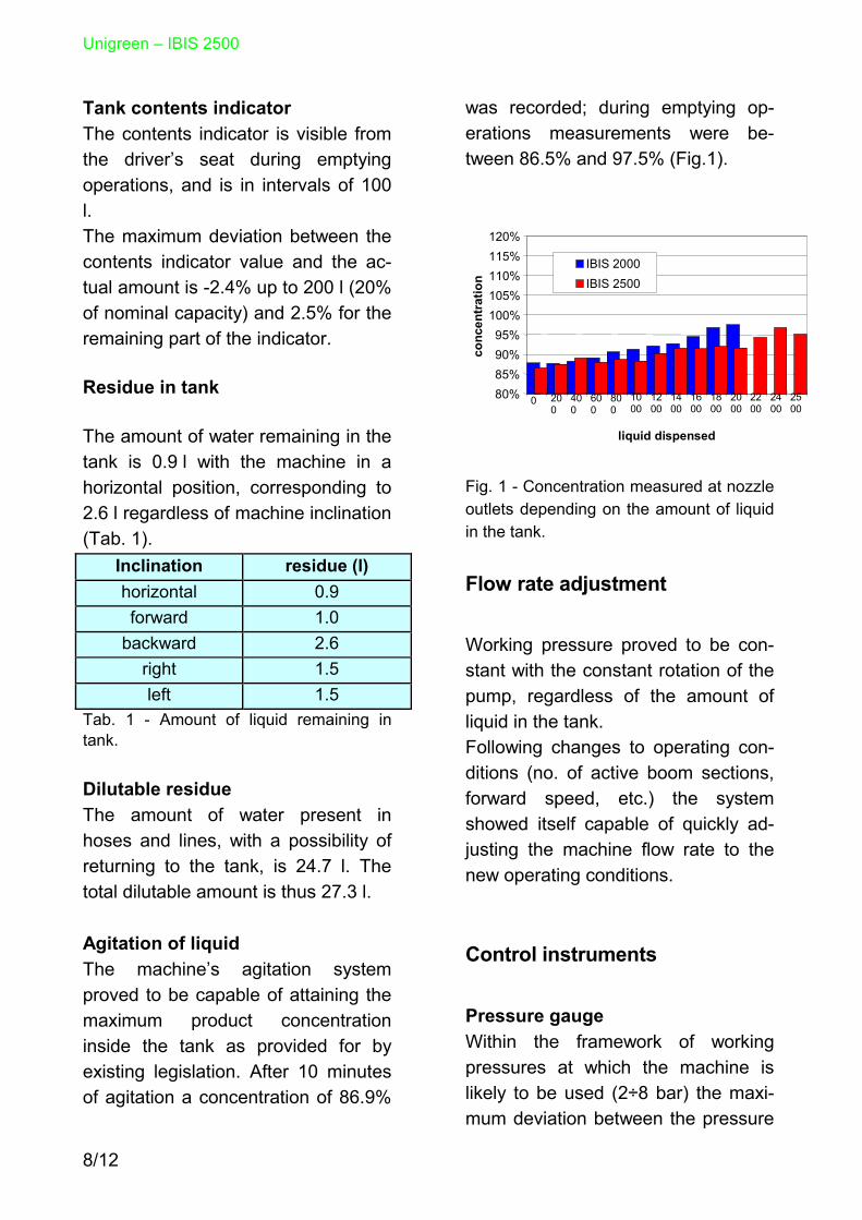
Tank contents indicator The contents indicator is visible from the driver’s seat during emptying operations, and is in intervals of 100 l. The maximum deviation between the contents indicator value and the ac-tual amount is -2.4% up to 200 l (20% of nominal capacity) and 2.5% for the remaining part of the indicator. Residue in tank The amount of water remaining in the tank is 0.9 l with the machine in a horizontal position, corresponding to 2.6 l regardless of machine inclination (Tab. 1).
Inclination residue (l) horizontal 0.9 forward 1.0
backward 2.6 right 1.5 left 1.5
Tab. 1 - Amount of liquid remaining in tank.
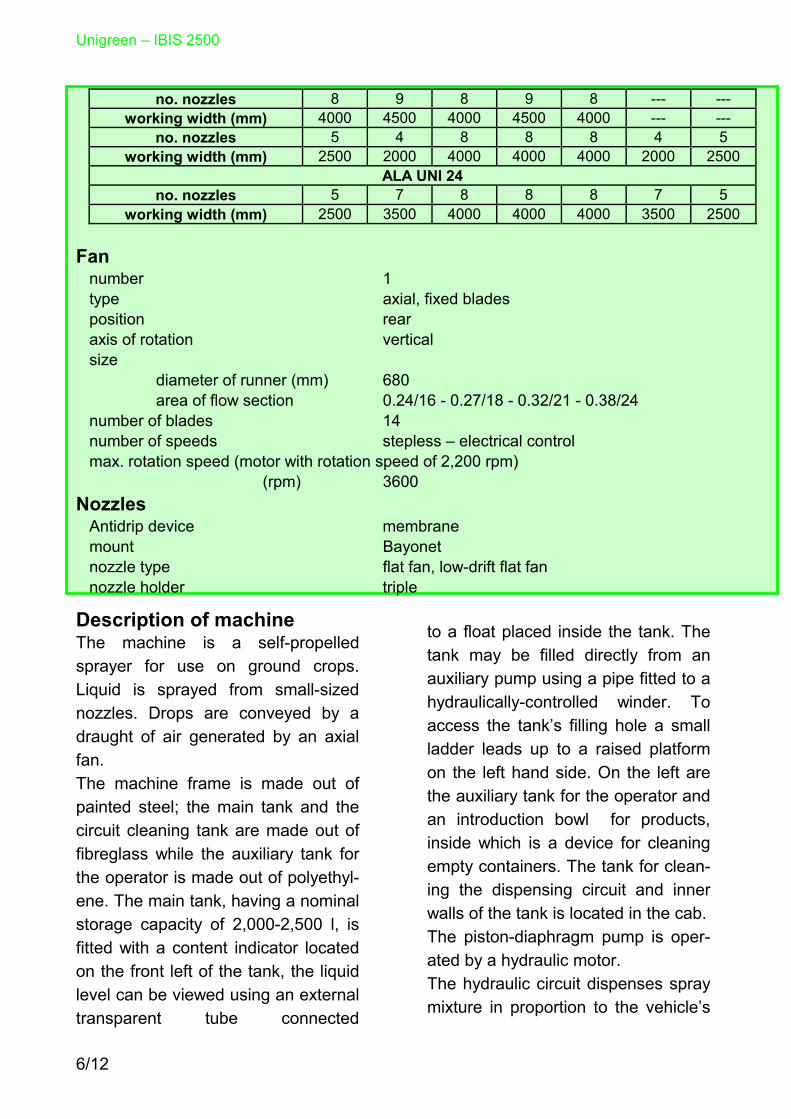
Dilutable residue The amount of water present in hoses and lines, with a possibility of returning to the tank, is 24.7 l. The total dilutable amount is thus 27.3 l. Agitation of liquid The machine’s agitation system proved to be capable of attaining the maximum product concentration inside the tank as provided for by existing legislation. After 10 minutes of agitation a concentration of 86.9%
was recorded; during emptying op-erations measurements were be-tween 86.5% and 97.5% (Fig.1).
80%85%90%95%
100%105%110%115%120%
0 200
400
600
800
1000
1200
1400
1600
1800
2000
2200
2400
2500
liquid dispensed(l)
conc
entr
atio
n
IBIS 2000IBIS 2500
Fig. 1 - Concentration measured at nozzle outlets depending on the amount of liquid in the tank. Flow rate adjustment Working pressure proved to be con-stant with the constant rotation of the pump, regardless of the amount of liquid in the tank. Following changes to operating con-ditions (no. of active boom sections, forward speed, etc.) the system showed itself capable of quickly ad-justing the machine flow rate to the new operating conditions. Control instruments Pressure gauge Within the framework of working pressures at which the machine is likely to be used (2÷8 bar) the maxi-mum deviation between the pressure

Unigreen– IBIS 2500
9/12
gauge value and the control pressure gauge is 0.03 bar (Fig.2).
-0.20
-0.15
-0.10
-0.05
0.00
0.05
0.10
0.15
0.20
2 3 4 5 6 7 8test pressure (bar)
devi
atio
n (b
ar)
Fig. 2 - Accuracy of the pressure gauge
Speed gauge The deviation between the actual speed and that indicated is in the region of -1% (Fig.3).
-3%
-2%
-1%
0%
1%
2%
3%
2 4 6 8 10 12 14 16forward speed (km/h)
devi
atio
n
Fig. 3 - Accuracy of speed gauge
Flow meter The meter showing the amount of liquid delivered gave results ranging from +1.5 to –0.8% (Fig.4).
-5%-4%-3%-2%-1%0%1%2%3%4%5%
20 40 60 80 100flow rate (l/min)
devi
atio
n
Fig. 4 - Accuracy of flow meter
Pressure drop The maximum difference between pressures measured at the beginning and at the end of the boom sections is 7.6%. Antidrip device The machine’s membrane antidrip devices were found to work in a regu-lar and correct manner.
Nozzle flow rate The mean flow rate of the machine’s nozzles is 0.82 l/min for the Teejet XR11002 nozzles, 1.54 l/min for the Teejet XR11004 nozzles and 2.28 l/for the Teejet XR11006 nozzles with a pressure of 3.0 bar (Table 2). Flow rate changes on the basis of working pressure are given in Fig.5.
Mean flow rate (l/min) nozzle mean max min
XR 11002 0.82 +3.3% -2.2% XR 11004 1.54 +2.6% -2.7% XR 11006 2.28 +2.2% -2.1%
Tab. 2 - Nozzle flow rate parameters

Unigreen – IBIS 2500
10/12
0
1
2
3
4
2 3 4 5
pressure (bar)
flow
rate
(l/i
)TeeJet XR 11002TeeJet XR 11004TeeJet XR 11006
Fig. 5 - Changes to nozzle flow rates on the basis of working pressure Regularity of transversal distri-bution Transversal distribution uniformity was measured at a working height of 600 mm and a working pressure of 3.0 bar. The uniformity of diagrams, ex-pressed as a coefficient of variation, is below 7%. Fan The speed of the hydraulically oper-ated fan can reach up to 3,600 rpm at a motor speed of 2,200 rpm. The fan air flow rate (m3/h) is:
fan speed (rpm) boom (m) 2000 3000 3600
16 19600 26900 30500 18 19900 29600 34500 21 20700 32500 38700 24 22600 35600 42000
The mean speed of outgoing air (measured at a distance of 0.5m below the nozzles) is:
boom (m) air speed (m/s) 16 7.9 18 7.4 21 7.0 24 6.8
Total residue The total amount of liquid in the ma-chine is:
width sec-tions
residue (l) limit (l)*
16 m 5 36.3 42.0 18 m 5 39.1 46.0 21 m 5 43.3 52.0 21 m 7 49.0 52.0 24 m 7 52.1 58.0 • limit referring to 2000 l tank
Notes on functionality The tested machine proved capable of supplying performance levels within the limits established by exist-ing legislation (Tab.3).

Unigreen – IBIS 2500
11/12
Parameter measured value limit accuracy of tank contents indicator
up to 20% of nominal capacity max. 2.4% ≤7.5% over 20% of nominal capacity max. 2.5% ≤5.0%
pressure drop max. 7.6% ≤10.0% uniformity of nozzle flow rate max. 2.7% ≤5.0% amount dripped 0 ml ≤2 ml horizontal distribution (CV) max. 6.3% ≤7.0% interruption of sections max 7.5% after 7 s 10% after 7 s speed changes max 7.2% after 7 s 10% after 7 s reproducibility of delivered volume (CV) max. 2.6% ≤3.0% agitation 86.5% - 97.5% ≥85% - ≤115% accuracy of pressure gauge max 0.03 bar ≤0.2 bar accuracy of speed gauge max. 1.2% ≤5.0% accuracy of flow meter max. 1.5% ≤5.0% Tab. 3 - Summary of measurements and comparison with legislative limits. Recommended conditions of use It may be stated, in light of the results of tests and machine performance, that the sprayer to which the present certifi-cate refers ensures a good uniformity of both transverse and longitudinal distri-bution in relation to the direction in which the vehicle is travelling. To adapt to different user needs (pre- or post-emergency weeding, fungicide treatment, etc.) nozzles having different flow rates may be fitted to the machine. On the basis of results obtained during certification testing, with special refer-ence to distribution diagrams, a working height in excess of 400 mm is recom-mended. To ensure that the machine attains the performance levels meas-ured it should operate with nozzles having a spray angle of 110°.
Testing of safety requirements The machine is endowed with CE mark-ing, an identification plate, safety picto-grams, a user and maintenance hand-book and an EC manufacturer’s decla-ration of conformity. The EC manufacturer’s declaration of conformity certifies that the machine conforms to the following harmonised standards and technical specifications: UNI EN 294:1993, UNI EN 907:1998; UNI EN 1553:2001; ISO 11684:1995. Checks carried out with reference to documentation sent by the manufac-turer did not show up inconsistencies with the contents of the aforementioned standards. The relative documentation has been filed.

12/12
THE PRESENT TEST REPORT IS VALID UNTIL REFERENCE REGULATIONS CHANGE FOR THE AIR-ASSISTED SPRAYER MODEL IBIS 2500 – ALA UNI 21 AND RELATIVE EXTENSIONS, MANUFACTURER: UNIGREEN S.P.A. THE PRESENT TEST REPORT IS OFFICIALLY RECOGNISED BY THE FOLLOWING ENTAM MEMBERS WITH THEIR RELATIVE RECOGNITION NUMBERS:
BBA - Federal Biological Research Centre for Agriculture and
Forestry - GERMANY n°. ENT-I-04/03
BLT - Bundesanstalt für Landtechnik Federal Institute of Agricultural
Engineering - AUSTRIA n°. 024/03
DIAS - Danmarks JordbrugsForskning Danish Institute of Agricultural
Sciences - DENMARK n°. 947-5a-33
EMA - Estación de Mecánica Agrícola – SPAIN n°. 06/03/5
FAT - Swiss Federal Research Station for Agricultural Economics
CH-8356 Tänikon and Engineering – SWITZERLAND n°. I-13.03
N.AG.RE.F - National Agricultural Research Foundation – GREECE
n°. ΛE/26/01/ZZ
ENAMA ENTE NAZIONALE PER LA MECCANIZZAZIONE AGRICOLA
(National Agricultural Mechanisation Body) VIA LAZZARO SPALLANZANI, 22/A - 00161 ROME
TEL. 06/4403137-4403872 FAX 06/4403712 email: [email protected] http://www.enama.it
is the European Network for Testing of Agricultural Machines and its purpose is to promote a cooperation among testing stations in order to optimize activities and give a better service to farmers, dealers and manufacturers. For more informations about the Members and activities please visit: www.entam.com or send an email to: [email protected]