Agilent PNA Series Microwave Network Analyzers€¦ · · 2010-01-13PNA Series Microwave Network...
28
Agilent PNA Series Microwave Network Analyzers Configuration Guide PNA-L N5230A 300 kHz to 6, 13.5, or 20 GHz PNA-L N5230A 10 MHz to 20, 40, or 50 GHz PNA E8362B 10 MHz to 20 GHz PNA E8363B 10 MHz to 40 GHz PNA E8364B 10 MHz to 50 GHz PNA E8361A 10 MHz to 67 GHz PNA N5250A 10 MHz to 110 GHz System configuration summary This summary lists the main components required to form a basic measurement system. Options or peripherals may be added to provide enhanced measurement and data storage capability. Full S-parameter measurements • Agilent PNA Series microwave network analyzers • Test port cables, 50 ohms • Calibration kit for applicable connector type This configuration guide describes standard configurations, options, accessories, upgrade kits and compatible peripherals for the PNA Series microwave network analyzers. This guide should be used with the Agilent PNA Series Microwave Network Analyzers, Data Sheet for a complete description of these analyzers.
Transcript of Agilent PNA Series Microwave Network Analyzers€¦ · · 2010-01-13PNA Series Microwave Network...

Agilent PNA SeriesMicrowave Network AnalyzersConfiguration Guide
PNA-L N5230A 300 kHz to 6, 13.5, or 20 GHzPNA-L N5230A 10 MHz to 20, 40, or 50 GHzPNA E8362B 10 MHz to 20 GHzPNA E8363B 10 MHz to 40 GHzPNA E8364B 10 MHz to 50 GHzPNA E8361A 10 MHz to 67 GHzPNA N5250A 10 MHz to 110 GHz
System configuration summary
This summary lists the main components required to form a basic measurement system. Options or peripherals may beadded to provide enhanced measurement and data storagecapability.
Full S-parameter measurements
• Agilent PNA Series microwave network analyzers
• Test port cables, 50 ohms• Calibration kit for applicable
connector type
This configuration guide describes standard configurations, options, accessories, upgrade kits and compatible peripherals for the PNA Series microwave network analyzers. This guide should be usedwith the Agilent PNA Series Microwave Network Analyzers, DataSheet for a complete description of these analyzers.

2
Step 1: Select N5230A model number
Step 2: Choose your frequency range and test set (Mandatory, choose only one)
Description Ordering number300 kHz to 6 GHz 2-port standard test set N52300-020300 kHz to 6 GHz 2-port configurable test set
and extended power range N52300-025300 kHz to 13.5 GHz 2-port standard test set N52300-120300 kHz to 13.5 GHz 2-port configurable test set
and extended power range N52300-12510 MHz to 20 GHz 2-port standard test set N52300-220 10 MHz to 20 GHz 2-port configurable test set
and extended power range N52300-225300 kHz to 20 GHz 4-port standard test set N52300-240300 kHz to 20 GHz 4-port configurable test set
and extended power range N52300-24510 MHz to 40 GHz 2-port standard test set N52300-42010 MHz to 40 GHz 2-port configurable test set
and extended power range N52300-42510 MHz to 50 GHz 2-port standard test set N52300-52010 MHz to 50 GHz 2-port configurable test set
and extended power range N52300-525
Step 3: Choose additional software options (Optional)Description Ordering numberTime domain for 6 GHz model N52310-010 Time domain for 13.5, 20, 40 or 50 GHz model N52300-010 Frequency-offset measurements N52300-080
Step 4: Choose an electronic or mechanical calibration kit (Optional)
Description Ordering number300 kHz to 9 GHz, 2-port, 3.5 mm 85093C300 kHz to 13.5 GHz, 4-port, Type-N N4431B
or 3.5 mm connectors300 kHz to 18 GHz, 4-port Type-N N4432A300 kHz to 20 GHz, 4-port 3.5 mm N4433A300 kHz to 26.5 GHz, 2-port 3.5 mm connectors N4691B10 MHz to 50 GHz, 2-port 2.4 mm connectors N4693ANote: For additional calibration kits refer to page 16
Step 5: Accessories (Optional)Description Ordering numberRack mount kit without handles N5230A-1CMRack mount kit with handles N5230A-1CPUSB CD R/W drive N4688AUSB Hub N4689ANote: For additional accessories refer to page 16
Step 6: Calibration documentation (Optional)Description Ordering numberISO 17025 compliant calibration N5230A-1A7Commercial calibration certificate with test data N5230A-UK6ANSI Z540 compliant calibration N5230A-A6J
Step 7: Choose your warranty and service (Optional)Description1 year return-to Agilent warranty and service 3 year return-to Agilent warranty and service
DocumentationThe PNA Series instruments are equipped with anOnline Help system available within the instrument inthe following languages: English, Japanese, Chinese,German, Spanish, and French. The PNA Service Guideand Online Help system are available on the Web:www.na.tm.agilent.com/pna
Connector type Option 020, 025, 120, 125, 220, 225, 240, 245:
3.5 mm ruggedized male, 50 ohmOption 420, 425, 520, 525:
2.4 mm ruggedized male, 50 ohm
Additional product information For additional PNA-L (N5230A) product information,refer to the PNA-L brochure available on our Web site:www.agilent.com/find/pnal
PNA-L (N5230A)
3
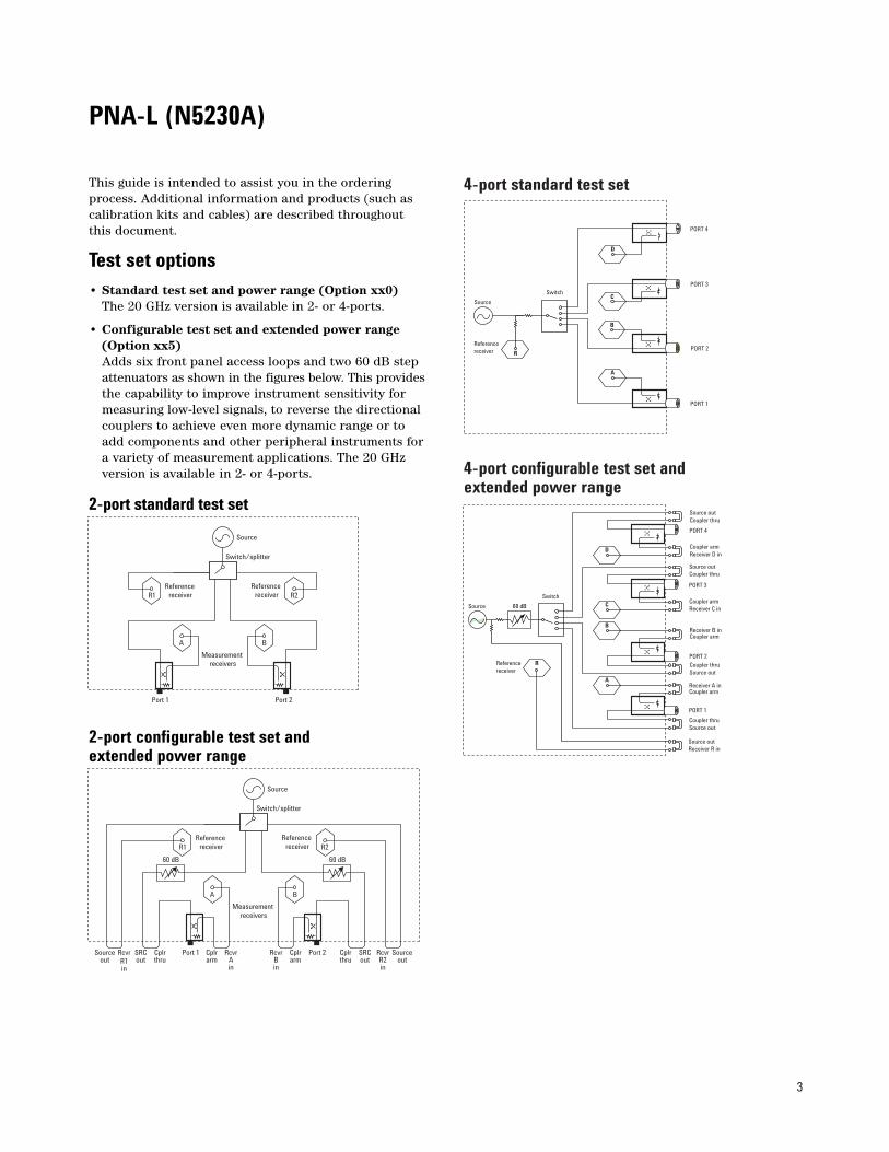
4-port standard test set
4-port configurable test set and extended power range
Source
Switch
PORT 4
Coupler armReceiver D in
Source outCoupler thru
PORT 3
Coupler armReceiver C in
Source outCoupler thru
PORT 2
Coupler thruSource out
Receiver B inCoupler arm
PORT 1
Coupler thruSource out
Receiver A inCoupler arm
D
RReferencereceiver
Source outReceiver R in
C
A
B
60 dB
This guide is intended to assist you in the orderingprocess. Additional information and products (such ascalibration kits and cables) are described throughoutthis document.
Test set options• Standard test set and power range (Option xx0)
The 20 GHz version is available in 2- or 4-ports.
• Configurable test set and extended power range (Option xx5)Adds six front panel access loops and two 60 dB step attenuators as shown in the figures below. This providesthe capability to improve instrument sensitivity for measuring low-level signals, to reverse the directional couplers to achieve even more dynamic range or to add components and other peripheral instruments fora variety of measurement applications. The 20 GHz version is available in 2- or 4-ports.
2-port standard test set
2-port configurable test set and extended power range
Source
Switch/splitter
Reference receiver
Reference receiver
Measurement receivers
Port 1 Port 2
A B
R1 R2
Source
Switch/splitter
Reference receiver
Reference receiver
Measurement receivers
Port 1 Port 2
60 dB
A
60 dB
B
R1 R2
Sourceout
RcvrR1in
SRCout
Cplrthru
Cplrarm
RcvrAin
RcvrR2in
Sourceout
RcvrBin
Cplrarm
Cplrthru
SRCout
Source
Switch
PORT 4
PORT 3
PORT 2
PORT 1
R
Referencereceiver
C
A
B
D
PNA-L (N5230A)

4
Additional options❑ Time domain (Option 010)This option enables the PNA Series to view reflectionand transmission responses in both time or distancedomain. Use time domain to tune filters, gate out theresponse of fixtures and cables, characterize the imped-ance of transmission line, and more.
❑ Frequency offset (Option 080)This option enables the PNA Series to set the source frequency independently from where the receivers aretuned. This ability is important for two general classesof devices: mixers (and converters) and amplifiers.
❑ 4-port measurement application (Option 550)Enables full, 4-port error correction and differentialmeasurements on a 2-port network analyzer. Externaltest set required. User installable.
Certification options❑ Commercial calibration certification with test data(Option UK6)Complete set of measurements which test unit to manufacturer’s published specifications. Includes calibration label, calibration certificate, and data report.Conforms to ISO 9001.
❑ ISO 17025 compliant calibration (Option 1A7)Complete set of measurements which tests unit to manufacturer’s published specifications. Includes calibration label, ISO17025 calibration certificate, anddata report, measurement uncertainties and guardbandson all customer specifications. Conforms to ISO 17025and ISO 9001.
PNA-L (N5230A)

5
PNA Network Analyzers1
E8361A/62B/63B/64B, N5250A
OptionsTo add options to a product, order the corresponding item number.
Description For E8362B For E8363B For E8364B For E8361A For N5250A Additional system3 information
Test setOption 014 • Configurable test set E8362B-014 E8363B-014 E8364B-014 E8361A-014 Included
Power configuration Option UNL • Extended power range E8362B-UNL E8364B-UNL E8364B-UNL E8361A-UNL Included Only E8361A
and bias-tees requires 014Option 016 • Add receiver attenuators E8362A-016 E8364A-016 E8364A-016 E8361A-016 E8361A-016 Requires UNL
(only E8361A alsorequires 014)
Option H85 • High-power configuration E8362B-H85 E8363B-H85 E8364B-H85 Contact Contact Includes 014, 016,Agilent Agilent UNL*4, 080, 081
Non-linear measurements Option 080 • Frequency offset E8362A-080 E8364A-080 E8364A-080 E8361A-080 Included Requires 014
(E8361A only, 081 required if UNL isalso purchased)
Option 081 • Reference receiver switch E8362A-081 E8364A-081 E8364A-081 E8361A-081 Included Requires 014, 080 (only E8361A also requires UNL)
Option 083 • Frequency converter E8362A-083 E8364A-083 E8364A-083 E8361A-083 E8361A-083 Requires 014, 080, measurement application 081(only E8361A
also requires UNL)includes GPIB to USBinterface (82357A)
Pulse, antenna, mm-wave Option H085 • Pulsed-RF measurement E8362B-H08 E8363B-H08 E8364B-H08 E8361A-H08 E8361A-H08
capabilityOption H11 • IF access (for antenna, E8362B-H11 E8363B-H11 E8364B-H11 E8361A-H11 Included Requires 014, UNL,
pulsed-RF and mm-wave 080, and 081measurements)
Measurement features Option 010 • Time-domain capability E8362A-010 E8363A-010 E8364A-010 E8361A-010 E8361A-010 Option 550 not compatible Option 550 • 4-port measurement application E8362B-550 E8363B-550 E8364B-550 E8361A-550 with N5250A systems
Accessories Option 1CM • Rack mount kit for use E8362A-1CM E8363A-1CM E8364A-1CM E8361A-1CM E8361A-1CM
without handles Option 1CP • Rack mount kit for use E8362A-1CP E8363A-1CP E8364A-1CP E8361A-1CP E8361A-1CP
with handlesN4688A • USB CD R/W drive N4688A N4688A N4688A N4688A N4688AN4689A • USB Hub N4689A N4689A N4689A N4689A N4689A
Calibration documentation Option 1A7 • ISO 17025 compliant E8362B-1A7 E8363B-1A7 E8364B-1A7 E8361A-1A7 E8361A-1A7
calibrationOption UK6 • Commercial calibration E8362A-UK6 E8363A-UK6 E8364A-UK6 E8361A-UK6 E8361A-UK6
certificate with test data Option A6J • ANSI Z540 compliant E8362B-A6J E8363B-A6J E8364B-A6J E8361A-A6J E8361A-A6J
calibrationNote: Item numbers may not correspond to product model number. For example, to order the time-domain option on the E8362B, the correct item number to order is E8362A-010.
Warranty and serviceOne, and three year warranty service plans are available at time of instrument purchase. The N5250A 110 GHz system carries a full one-year on-site warranty (where available).
CalibrationThree year calibration plans are available at time of instrument purchase.
1. All models are not available in all countries.2. For more detailed information regarding the 110 GHz network analyzer system, refer to the Agilent Web site: www.agilent.com/find/pna
and download the N5250A Technical Overview, literature number 5988-9620EN. 3. The N5250A 110 GHz system also includes an N5260A millimeter-wave test set controller, 1.0 mm combiner assembly, interconnecting cables,
and installation and productivity assistance. See page 12 for more details.4. UNL* does not include bias-tees. Only includes source attenuators.5. Up to 67 GHz.
PNA (highest performance series)E8362B 10 MHz to 20 GHzE8363B 10 MHz to 40 GHzE8364B 10 MHz to 50 GHzE8361A 10 MHz to 67 GHzN5250A2 10 MHz to 110 GHz

6
Agilent PNA Network AnalyzersThe microwave PNA Series instruments are integratedvector network analyzers equipped with a built-in S-parameter test set, synthesized source, hard and floppy disk drives, and LCD display. The E8362B analyzer has two 50 ohm, 3.5 mm (m) test ports. TheE8363B and E8364B analyzers have two 50 ohm, 2.4 mm (m) test ports. The E8361A analyzer has two 50 ohm, 1.85 mm (m) test ports. Included with eachinstrument is a mouse, keyboard (U.S.), CD-ROM containing a copy of on-line Help and programming documentation,and a 1-year return-to-Agilent service warranty.
❍ E8362B network analyzer, 10 MHz to 20 GHz ❍ E8363B network analyzer, 10 MHz to 40 GHz ❍ E8364B network analyzer, 10 MHz to 50 GHz ❍ E8361A network analyzer, 10 MHz to 67 GHz1
❍ N5250A network analyzer system, 10 MHz to 110 GHz
Options
❑ Time-domain capability (Option 010) For viewing reflection and transmission responses in time or distance domain.
❑ Configurable test set (Option 014)2
Provides six front panel access loops. Three access loops are for port one and three for port two. The loops provide access to the signal path between (a) the source output and the reference receiver, (b) the source output and directional coupler thru arm and (c) the coupled arm of the directional coupler and theport receiver. This option provides the capability to improve instrument sensitivity for measuring low-level signals, to reverse the directional coupler to achieve even more dynamic range or to add components and other peripheral instruments for a variety of measurement applications.(see PNA Series Microwave Data Sheet literature number 5988-7988EN for a basic block diagram)
❑ 4-port measurement application (Option 550)3
Enables full, 4-port error correction and differential measurements on a 2-port network analyzer. Externaltest set required.
❑ Extended power range and bias-tees (Option UNL)2
Adds two 60 dB step attenuators and two bias-tees to the E8362/3/4B. Adds two 50 dB step attenuators andtwo bias-tees to the E8361A. A step attenuator and bias-tee set is inserted between the source and test port one and another set between the source and test port two. (see PNA Series Microwave Data Sheet literature number 5988-7988EN for a basic block diagram)
❑ Frequency offset (Option 080)2 This option enables the PNA Series microwave network analyzers to set the source frequency independently from where the receivers are tuned. This ability is important for two general classes of devices: mixers (and converters) and amplifiers. Option 080 provides a very basic user interface.
❑ Reference receiver switch (Option 081)2 Option 081 addsa solid-state internal RF transfer switch in the R1 reference-receiver path (see PNA Series Microwave Data Sheet literature number 5988-7988EN for a basicbasic block diagram). The switch allows the instrumentto easily switch between standard S-parameter (non-frequency-offset) measurements and frequency offset measurements such as relative phase or absolute group delay that require an external reference mixer. The user can set the switch manuallyor remotely, but it is best used with the frequency-converter application (Option 083), where it is controlled automatically during the vector-mixer calibration procedure and subsequent measurements.
❑ Frequency-converter measurement application (Option 083)2
The frequency-converter application adds an intuitiveand easy-to-use user interface, advanced calibration choices that provide exceptional amplitude and phaseaccuracy, and control of external signal sources for use as local oscillators. Mixer calibration techniques include scalar-mixer calibration and vector-mixer calibration (requires Option 081). Finally, the frequency-converter application supports all of Agilent’s major signal source families. Option 083 includes a GPIB to USB interface (82357A) for control of external sources and power meters.
1. The E8361A can be extended to 110 GHz with IF access (Option H11).2. Up to 67 GHz.3. Not compatible with N5250A.

7
❑ High-power test set (Option H85) This configuration combines options that are often necessary for high power measurements (UNL*1, 014, 016, 080, 081). The only difference between ordering Option H85 versus a combination of the options listed above is the source attenuator option UNL. Standard UNL includes two source attenuators and two bias-tees. Option H85 includes the two source attenuators, but not the bias-tees, as the bias-tees are the power-limiting factorin the network analyzer test set. The maximum powerat the test port is +43 dBm (<20 GHz), and +40 dBm (>20 GHz).
Option 080, frequency-offset mode, is included in option H85 because it manages the phase-locking internally (instead of depending on the R1 receiver). So if you need to use external components in the pathof the R1 receiver, it makes the measurements simplerand more robust.
❑ Rack mount kit without handles (Option 1CM)Adds a rack mount (5063-9217) and rail kit (E3663AC) for use without handles.
❑ Rack mount kit with handles (Option 1CP)Adds a rack mount (5063-9237)3 and rail kit (E3663AC) for use with standard supplied handles.
DocumentationPNA Online Help system is available within PNA instru-ments in the following languages: English, German,Spanish, French, Japanese, and Chinese.
The PNA Service Guide and Online Help are available onthe Web: http://na.tm.agilent.com/pna
❑ Add receiver attenuators (Option 016) An attenuator is added between each test port and its corresponding receiver. Two 35 dB step attenuators are added to the E8362/3/4B. Two 50 dB step attenuators are added tothe E8361A (see PNA Series Microwave Data Sheet literature number 5988-7988EN for a basic block diagram).
❑ Pulsed-RF measurement capability (Option H08)2 Provides software to set up and control pulsed-RF measure-ments with point-in-pulse capability. The software sets the coefficient of the PNA’s digital-IF filter to nullout unwanted spectral components, enables the IF gates provided with IF access (Option H11), and controls selected Agilent pulse generators. It can be run on the PNA or an external computer. A “.dll” file containing the IF-filter algorithms is included for automated pulsed-RF testing. The pulsed application isconfigured to work with the Agilent 81110A series pulse generator.
For more detailed information regarding pulsed measurement capabilities with the microwave PNA refer to the Agilent Web site www.agilent.com/find/pnaand download the PNA Series MW Network AnalyzersConfiguration Guide for Pulsed Measurements, literature number 5988-9833EN.
❑ IF access (Option H11) Provides hardware to enable antenna, point-in pulse, and broadband millimeter-wave measurements to 110 GHz. For each of the MW PNA’s measurement receivers, IF gates (enabled with pulsed measurement capability, Option H08) and external IF inputs are added. In addition, access to the PNA’s internal RF and LO source is provided for remote mixing applications. For basic antenna measurements, only Option H11 is necessary. Pulsed antenna applications also require the pulsed measurement capability (Option H08). Broadband measurements to 110 GHz, also requires an N5260A millimeter-wave test set controller.
Note: Use external IF access for up to 20 dB more sensitivity when making antenna measurements with a remote mixing configuration. Add Option H08 (Pulsed-RF Measurement Capability) to enable advanced pulsed measurements. Or upgrade to a broadband (10 MHz to 110 GHz) VNA system simply by purchasing an N5260A controller test set with test heads (Option 110, 120, or 130).
1. UNL* does not include bias-tees. Only includes source attenuators.
2. Up to 67 GHz.
3. The 5063-9237 kit assumes you have the standard handles shipped
with the instrument. If you do not have handles, order a 5063-9224 kit.

8
Certification options
❑ Commercial calibration certificate with test data (Option UK6)Complete set of measurements which tests unit to manufacturer’s published specifications. Includes calibration label, calibration certificate, and data report. Conforms to ISO 9001.
❑ ISO 17025 compliant calibration (Option 1A7) Complete set of measurements which tests unit to manufacturer’s published specifications. Includescalibration label, ISO 17025 calibration certificate, and data report, measurement uncertainties and guardbands on all customer specifications. Conforms to ISO 17025 and ISO 9001.
❑ ANSI Z540 compliant calibration (Option A6J)Complete set of measurements which tests unit to manufacturer’s published specifications. Includespre and post-adjustment data with measurement uncertainity information compliant to the ANSI/NCSLZ540 standard.
Warranty and service1 and 3 year warranty and service plans are available attime of instrument purchase. Standard warranty is 1year.
Calibration3 year calibration plans are available at time of instru-ment purchase. Contact your local Agilent sales officefor details.
Product servicesAgilent product services provide tailored assistancerelated to a specific need or application. Product servicesenable you to quickly learn how Agilent instrumentsoperate, their capabilities, and how to apply that knowledge to achieve your specific measurement goals.PNA series services available include:
• Remote scheduled productivity assistance• 1 Day of start-up assistance• Daily productivity assistance• PNA operator training for 8 students at your
business site• PNA operator web classes for 1 student• Custom services to be qualified by an Agilent
technical consultant
E8361A/62B/63B/64BConfiguration DetailsSelecting the correct mixer-test configuration:
Most mixer or converter test applications requireOptions 014, 080, 081, and 083. If you want to createand automate your own custom frequency-offset meas-urements (for example, intermodulation distortion), you may only need Options 014 and 080. For convertersthat require input power below -27 dBm, or for devicesthat have a large amount of LO feedthrough (like anunfiltered mixer), Option UNL, which adds source attenuators, is highly recommended. Besides allowinglower input power levels, these attenuators improve the isolation between the PNA’s internal source and LO leakage signals, helping to prevent source-unlevelederrors. For devices that put out signals near or abovethe receiver’s compression levels (which varies between–3 and +5 dBm, depending on the model and frequency),Option 016 is recommended, which adds receiver atten-uators. Finally, Option 010, which adds time-domainanalysis, is very useful for gating out unwanted, time-delayed responses which often occur when measuring mixers.

9
Microwave PNA Network Analyzer
Simplified test set block diagrams
Standard power range
Extended power range and bias-tees (Option UNL)
Source
Switch/splitter
Reference receiver
Reference receiver
Measurement receivers
Port 1 Port 2
A B
R1 R2
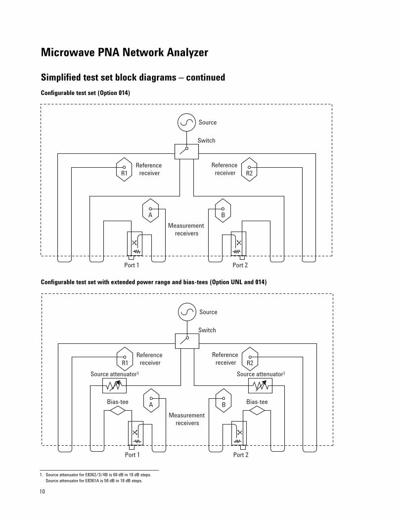
1. Source attenuator for E8362/3/4B is 60 dB in 10 dB steps. Source attenuator for E8361A is 50 dB in 10 dB steps.
Source
Switch
Reference receiver
Reference receiver
Measurement receivers
Port 1 Port 2
A B
R1 R2
Source attenuator1Source attenuator1
Bias-teeBias-tee
10
Microwave PNA Network Analyzer
Simplified test set block diagrams – continued
Configurable test set (Option 014)
Configurable test set with extended power range and bias-tees (Option UNL and 014)
Source
Switch
Reference receiver
Reference receiver
Measurement receivers
Port 1 Port 2
A B
R1 R2
Source
Switch
Reference receiver
Reference receiver
Measurement receivers
Port 1 Port 2
Bias-tee
Source attenuator1
A Bias-tee
Source attenuator1
B
R1 R2
1. Source attenuator for E8362/3/4B is 60 dB in 10 dB steps. Source attenuator for E8361A is 50 dB in 10 dB steps.

11
Microwave PNA Network Analyzer
Simplified test set block diagrams – continued
Source
Switch/splitter/leveler
Reference receiver
Reference receiver
Measurement receivers
Cplrarm
Bias-tee
Source attenuator1
A Bias-tee
Source attenuator1
B
R1 R2
10 dB steps 10 dB steps
Receiver attenuator2
Rcvr Bin
Rcvr Ain
Cplrarm
SRCout
Cplrthru
Sourceout
Rcvr R2 in
Cplrthru
SRCout
Rcvr R1in
Sourceout
Option 081
Fully optioned, active device or mixer/converter test configuration (Options 014, UNL, 016, 080, 081)
1. Source attenuator for E8362/3/4B is 60 dB in 10 dB steps. Source attenuator for E8361A is 50 dB in 10 dB steps.
2. Receiver attenuator for E8362/3/4B is 35 dB in 5 dB steps. Receiver attenuator forE8361A is 50 dB in 10 dB steps.

12
Microwave PNA Network Analyzer
Simplified test set block diagrams – continued
Source
Switch/splitter/leveler
Reference receiver
Reference receiver
Measurement receivers
Cplrarm
A B
R1 R2
10 dB steps 10 dB steps
Receiver attenuator2
Rcvr Bin
Rcvr Ain
Cplrarm
SRCout
Cplrthru
Sourceout
Rcvr R2 in
Cplrthru
SRCout
Rcvr R1in
Sourceout
Option 081
DU
T
+40dBm
+30dBm
+15dBm
+30dBm
+30dBm
+15dBm
+15dBm
+40dBm
+15dBm
preamp
Source attenuator1 Source attenuator1
+30dBm
+30dBm
1. Source attenuator for E8362/3/4B is 60 dB in 10 dB steps. Source attenuator for E8361A is 50 dB in 10 dB steps.
2. Receiver attenuator for E8362/3/4B is 35 dB in 5 dB steps. Receiver attenuator forE8361A is 50 dB in 10 dB steps.
Power levels shown on the diagram are damage levels. At a minimum, keep power levels 6 dB below damage level.For optimal performance, keep the power level incident upon the receivers -20 dBm or less. This will keep thereceivers out of compression.
High-power configuration (Option H85)

13
Microwave PNA Network Analyzer
Simplified test set block diagrams – continued
Option 016Receiver
attenuators
Port 1 Port 2
Option UNL
Option UNL
Option UNL
Option UNL
IF gate
ADC
ExternalIF in
Option H111
R2
ADC
ExternalIF in
Option H111B
ADC
ExternalIF in
Option H111
R1
IF gate
ADC
ExternalIF in
Option H111 A
LO
Option H11Multipliers(1, 2)
Multipliers (1, 2, 4)
YIG source
8.33 MHzreference
OffsetLO
Phase-locked loop
Vtune
Option 080
Option 081
Option 014Option 014 Option 014
Front
Rear
Aux RF out(2 to 20 GHz)
Aux LO out(2 to 20 GHz)
Offset receiver
IF gate
IF gate
Fully optioned, pulse-RF, antenna, or mm-wave configuration (Options 014, UNL, 016, 080, 081, H11)
1. Option H11: IF-gate controls and external-IF inputs are accessed on rear panel. IF gates are enabled with Option H08. External-IF input frequency is 8.33 MHz.

14
N5250A Configuration Details❑ N5250A MW PNA system1, 10 MHz to 110 GHz, includes:
E8361A MW PNA with IF access (Option H11)• Configurable test set – Option 014 (required)• Extended power range and bias-tees –
Option UNL (required)• Frequency-offset mode – Option 080 (required)• Reference channel switch – Option 081
(required)N5260A millimeter-wave test set controller with test heads
• 67 GHz test heads• 1.0 mm combiner assembly• Interconnecting cables• Installation and productivity assistance
Additional options available:• Millimeter-wave modules with bias-tees -
Option 017• Millimeter-wave modules with bias-tees and
port 2 attenuator - Option 018• Receiver attenuator – Option 016 • Time-domain capability – Option 010• Extended memory (512 MB) –Option 022• Pulsed-RF measurement capability – Option H082
• Frequency converter application – Option 0832
Factory integration of the N5250A system integrates the E8361A with Option H11 and the N5260A millimeter-wave controller with test heads. On-site installation isincluded, and the entire system carries a full one-year,on-site warranty (where available).
Option Descriptions
❑ Millimeter-wave modules with bias-tees (Option 017)Adds 67 GHz bias-tees to the combiner assemblybetween the input to the combiner and the 67 GHz coupler.The bias-tees have tri-axial connectors for force, sense,and ground. Positioning the bias-tees close to the DUTgreatly improves stability for on-wafer and in-fixturedevices. The bias-tees added for this option have a voltagerating of 40 volts and a maximum of 0.5 amps.
❑ Millimeter-wave modules with bias-tees and port 2 attenuator (Option 018)
Adds 67 GHz bias-tees to the combiner assembly betweenthe input to the combiner and the 67 GHz coupler. Thebias-tees have tri-axial connectors for force, sense, andground. Positioning the bias-tees close to the DUT greatlyimproves stability for on-wafer and in-fixture devices.The bias-tees added for this option have a voltage ratingof 40 volts and a maximum of 0.5 amps. Additionally,Option 018 adds a 25 dB micrometer attenuator to theport 2 test head.
Banded waveguide solutionIn order to assemble a banded waveguide solution, thefollowing components are needed:• Microwave PNA network analyzer (E8361A or
E8362/3/4B) with the following options:• IF access - Option H11• Configurable test set - Option 014• Extended power range and bias-tees - Option UNL• Frequency-offset mode - Option 080• Reference channel switch - Option 081• Millimeter-wave test set controller (N5260A)
with no options• A set of waveguide modules:
• N5260AW15, 50 to 75 GHz• N5260AW12, 60 to 90 GHz• N5260AW10, 75 to 110 GHz• N5260AW08, 90 to 140 GHz• N5260AW06, 110 to 170 GHz• N5260AW05, 140 to 220 GHz• N5260AW03, 220 to 325 GHz
NOTE: To significantly improve system dynamic rangeabove 220 GHz, Agilent strongly recommends addingtwo external synthesizers such as Agilent’s PSG Seriessignal generators; one for the RF signal, and one for theLO signal.
For more detailed information, see PNA Millimeter-waveTechnical Overview, literature number 5988-9620EN.
On-wafer applicationsFor on-wafer applications, Cascade Microtech3 providescomplete probing systems using the N5250A. Theseinclude both new probing systems and upgrades toexisting Cascade Microtech products. Cascade can alsoprovide on-wafer verification and probing system training. Once the N5250A system is verified in coax,Cascade Microtech will verify the system through itswafer probes.
1. For more detailed information regarding the 110 GHz network analyzer system, refer to the Agilent Web site: www.agilent.com/find/pna and download the N5250A Technical Overview, literature number 5988-9620EN.
2. Up to 67 GHz.3. Cascade Microtech is an Agilent Channel Partner.

15
N5250A Millimeter-Wave PNA Block Diagram
Reference receiver
Reference receiver
Option 016receiver
attenuators
Port 1 Port 2
Bias-tee
50 dB
A
Bias-tee
50 dB
B
R1 R2
LO distribution toeach receiver
To IF multiplexer(see Figure 5)
To IF multiplexer(see Figure 5)
LO: 2 to 20 GHzR1IF
R2IF
AIF
BIF
R1gate
R2gate
Agate
BgateRF: 2 to 20 GHz
IF multiplexer
A/D
ExternalIF input
IF gating
RF
LO(from LO distribution.
See test setblock diagram)
SMAconnectors
BNCconnectors
SMAconnectors
BNCconnectors
50 dB 50 dB
Receiver A Receiver B
Port 1 Port 2
67 to 110 GHzwaveguide head
67 to 110 GHzwaveguide head
IF1 IF2 IF3 IF4
Test set I/O
LO RF
Combiner assembly
Testport 1
Testport 2
E8361Awith Option H11
N5260Awith
test heads
30 in.76.2 cm
48 in.121.9 cm
30 in.76.2 cm
48 in.121.9 cm
Combiner assembly
Optionalbias-tees
(Option 017)
Test set controller
PNA test set block diagram
Simplified receiver block diagram
With Option 017, the signal is routed out ofthe PNA from the front panel jumpersrather than the ports. Without Option 017,the signal is routed from the front panelports to the combiner assembly, allowingaccess to the PNA’s internal bias-tees.

16
Network analyzertest set
Network analyzertest set
Test portadapterDevice
undertest
Single cableDeviceundertest
Cable set
Measurement AccessoriesA complete list of RF and microwave test accessoriesis available on our Web site: www.agilent.com/find/accessories
Accessories are available in these connector types: 50 ohm Type-N, 3.5 mm, 7 mm, 2.4 mm, 2.92 mm, 1.85 mm, 1.0 mm, and waveguide. Test port cables and a calibration kit should be added for a complete measurement system. A verification kit is used to verify corrected system performance.
Cables and adapter setsAgilent offers cables in the following types:• single cables in semi-rigid and flexible • cable sets in semi-rigid and flexible
There are also adapter sets available that protect thetest port and convert the port to the desired connectorinterface. These kits contain:• one male adapter • one female adapter
To attain the best mechanical rigidity for device connection, use a single cable and the appropriate special adapter set. To attain the greatest flexibility fordevice connection, use a cable set.
Calibration kits
Coaxial measurementsMechanical calibration kits include standards, such as opens, shorts and loads, which are measured by thenetwork analyzer for increased measurement accuracy.
Electronic calibration (ECal) kits replace mechanicalcalibration standards with one solid-state calibrationmodule that is controlled by the network analyzer viaUSB, to present many different impedances to the testports. A full two-port calibration can be performedquickly with a single connection. This technique reduces operator errors and connector wear and abrasion.
Choose a calibration kit for each connector type to be used.
Economy, includes:• open standards (male and female)• short standards (male and female)• fixed-termination standards (male and female)
Standard, includes the devices in the economy kit and adds:• sliding load standards (male and female) or a series of
offset shorts
Precision, includes the devices in the economy kit and adds:• 50 ohm airline(s) for TRL calibration• TRL adapters
Waveguide measurementsFor waveguide measurements, Agilent offersmechanical calibration kits that include:• waveguide-to-coax adapters (X, P, K, R, Q, U, V)• precision waveguide section• flush short circuit• fixed terminations• straight section

17
For devices with 1.0 mm connectors
Mechanical calibration/verification kit❑ 85059A DC to 110 GHz precision calibration/verification
kit. Includes:85059-60003 1.00 mm (m) short 2.450 mm85059-60007 1.00 mm (f) short 2.450 mm85059-60004 1.00 mm (m) short 3.000 mm85059-60008 1.00 mm (f) short 3.000 mm85059-60002 1.00 mm (m) short 1.825 mm85059-60006 1.00 mm (f) short 1.825 mm85059-60001 1.00 mm (m) short 1.300 mm85059-60005 1.00 mm (f) short 1.300 mm85059-60009 1.00 mm male open85059-60010 1.00 mm female open85059-60019 1.00 mm male load85059-60020 1.00 mm female load85059-60021 1.00 mm lossy delay line11920-60001 1.00 mm (m) to 1.00 mm (m) adapter 11920-60002 1.00 mm (f) to 1.00 mm (f) adapter11920-60003 1.00 mm (m) to 1.00 mm (f) adapter11500-60001 1.00 mm (f) to 1.00 mm (f) 8.8 cm cable85059-60016 1.00 mm mismatch thru adapter
for verification85059-60017 1.00 mm matched thru adapter
for verification8710-2079 6 mm, 4 in-lb torque wrench8710-2156 6 mm open end wrench
Cables❑ 11500I 1.0 mm (f-f) test port cable (8.8 cm)❑ 11500J 1.0 mm (m-f) test port cable (16.0 cm)1
❑ 11500K 1.0 mm (m-f) test port cable (20.0 cm)1
❑ 11500L 1.0 mm (m-f) test port cable (24.0 cm)1
Adapter set❑ V281C 1.0 mm(f) to V-band waveguide adapter❑ V281D 1.0 mm (m) to V-band waveguide adapter❑ W281C 1.0 mm (f) to W-band waveguide adapter❑ W281D 1.0 mm (m) to W-band waveguide adapter❑ 11920A 1.0 mm (m) to 1.0 mm (m) adapter❑ 11920B 1.0 mm (f) to 1.0 mm (f) adapter❑ 11920C 1.0 mm (m) to 1.0 mm (f) adapter❑ 11921A 1.0 mm (m) to 1.85 mm (m) adapter❑ 11921B 1.0 mm (f) to 1.85 mm (f) adapter❑ 11921C 1.0 mm (m) to 1.85 mm (f) adapter❑ 11921D 1.0 mm (f) to 1.85 mm (m) adapter❑ 11922A 1.0 mm (m) to 2.4 mm (m) adapter❑ 11922B 1.0 mm (f) to 2.4 mm (f) adapter❑ 11922C 1.0 mm (m) to 2.4 mm (f) adapter❑ 11922D 1.0 mm (f) to 2.4 mm (m) adapter❑ 11923A 1.0 mm (f) connector launch assembly
For devices with 1.85 mm connectors
Mechanical calibration kits❑ 85058B standard: DC to 67 GHz.
Includes:85058-60101 1.85 mm (m) short 5.4 mm85058-60102 1.85 mm (m) short 6.3 mm85058-60103 1.85 mm (m) short 7.12 mm85058-60104 1.85 mm (m) short 7.6 mm85058-60105 1.85 mm (f) short 5.4 mm85058-60106 1.85 mm (f) short 6.3 mm85058-60107 1.85 mm (f) short 7.12 mm85058-60108 1.85 mm (f) short 7.6 mm85058-60109 1.85 mm male open85058-60110 1.85 mm female open85058-60111 1.85 mm male load85058-60112 1.85 mm female load85058-60113 1.85 mm (m) to 1.85 mm (m) adapter85058-60114 1.85 mm (f) to 1.85 mm (f) adapter85058-60115 1.85 mm (m) to 1.85 mm (f) adapter
❑ 85058E economy: DC to 67 GHz. Includes:85058-60101 1.85 mm (m) short 5.4 mm85058-60105 1.85 mm (f) short 5.4 mm85058-60109 1.85 mm male open85058-60110 1.85 mm female open85058-60123 1.85 mm male load85058-60124 1.85 mm female load85058-60113 1.85 mm (m) to 1.85 mm (m) adapter85058-60114 1.85 mm (f) to 1.85 mm (f) adapter85058-60115 1.85 mm (m) to 1.85 mm (f) adapter
Electronic calibration kits❑ N4694A Microwave ECal: 10 MHz to 67 GHz, 2 ports.
Includes:Option M0F module with:
N4694-60001 1.85 mm (f) to 1.85 mm (m) ECal moduleOption 00M module with:
N4694-60002 1.85 mm (m) to 1.85 mm (m) ECal moduleOption 00F module with:
N4694-60003 1.85 mm (f) to 1.85 mm (f) ECal moduleOption 00A adds:
85058-60113 1.85 mm (m) to 1.85 mm (m) adapter85058-60114 1.85 mm (f) to 1.85 mm (f) adapter
Cables2
❑ N4697E Single, flexible: 1.85 mm (f) to 1.85 mm (f), 96.5 cm, 38 inches
❑ N4697F Set, flexible: One 1.85 mm (f) to 1.85 mm (f) cable, 62.2 cm, 24.5 inches, p/n N4697-60100One 1.85 mm (f) to 1.85 mm (m) cable, 62.2 cm, 24.5 inches, p/n N4697-60200
Adapter set❑ 85130H 1.85 mm2 to 1.85 mm
1. For on-wafer applications, two 11500J/K/L cables are required; one cable for each test port.
2. Special rugged female connector specifically for connecting to the network analyzer test port, but does not mate with a standard male connector.

18
For devices with 2.4 mm connectorsMechanical calibration kits❑ 85056A standard: DC to 50 GHz.
Includes:00901-60003 2.4 mm (m) fixed broadband load00902-60004 2.4 mm (f) fixed broadband load00915-60003 2.4 mm (m) sliding load00915-60004 2.4 mm (f) sliding load85056-60005 2.4 mm (m) to 2.4 mm (m) adapter85056-60006 2.4 mm (f) to 2.4 mm (f) adapter85056-60007 2.4 mm (m) to 2.4 mm (f) adapter85056-60020 2.4 mm (m) short85056-60021 2.4 mm (f) short85056-60022 2.4 mm (m) open85056-60023 2.4 mm (f) open
❑ 85056D economy: DC to 50 GHz. Includes:00901-60003 2.4 mm (m) fixed broadband load00902-60004 2.4 mm (f) fixed broadband load85056-60005 2.4 mm (m) to 2.4 mm (m) adapter85056-60006 2.4 mm (f) to 2.4 mm (f) adapter85056-60007 2.4 mm (m) to 2.4 mm (f) adapter85056-60020 2.4 mm (m) short85056-60021 2.4 mm (f) short85056-60022 2.4 mm (m) open85056-60023 2.4 mm (f) open
Electronic calibration kits❑ N4693A Microwave ECal: 10 MHz to 50 GHz, 2 ports.
Includes:Option M0F module with:
N4693-60001 2.4 mm (f) to 2.4 mm (m) ECal moduleOption 00M module with:
N4693-60002 2.4 mm (m) to 2.4 mm (m) ECal moduleOption 00F module with:
N4693-60003 2.4 mm (f) to 2.4 mm (f) ECal moduleOption 00A adds:
85056-60005 2.4 mm (m) to 2.4 mm (m) adapter85056-60007 2.4 mm (f) to 2.4 mm (f) adapter
Cables 1
❑ 85133C single, semi-rigid: 2.4 mm (f) to PSC-2.4 mm (f),81 cm, 32 inches
❑ 85133D set, semi-rigid: One 2.4 mm (f) to 2.4 mm (m), 53 cm, 21 inches, p/n 85133-60001One 2.4 mm (f) to 2.4 mm (f), 53 cm, 21 inches, p/n 85133-60002
❑ 85133E single, flexible: 2.4 mm (f) to PSC-2.4 mm (f), 97 cm, 38 inches
❑ 85133F set, flexible: One 2.4 mm (f) to 2.4 mm (f), 63 cm, 25 inches, p/n 85133-60016One 2.4 mm (f) to 2.4 mm (m), 63 cm, 25 inches, p/n 85133-60017
Adapter set❑ 85130G 2.4 mm1 to 2.4 mm
For devices with K connectors (2.92 mm)Mechanical calibration kits❑ 85056K 2.92/2.4 economy: DC to 40/50 GHz.
Includes:00901-60003 2.4 mm (m) fixed broadband load00902-60004 2.4 mm (f) fixed broadband load00915-60003 2.4 mm (m) sliding load (Option 001)00915-60004 2.4 mm (f) sliding load (Option 001)11904-60001 2.4 mm (m) to 2.92 mm (m) adapter11904-60002 2.4 mm (f) to 2.92 mm (f) adapter11904-60003 2.4 mm (m) to 2.92 mm (f) adapter11904-60004 2.4 mm (f) to 2.92 mm (m) adapter85056-60005 2.4 mm (m) to 2.4 mm (m) adapter85056-60006 2.4 mm (f) to 2.4 mm (f) adapter85056-60007 2.4 mm (m) to 2.4 mm (f) adapter85056-60020 2.4 mm (m) short85056-60021 2.4 mm (f) short85056-60022 2.4 mm (m) open85056-60023 2.4 mm (f) open
Electronic calibration kits❑ N4692A Microwave ECal: 10 MHz to 40 GHz, 2 ports.
Includes:Option M0F module with:
N4692-60001 2.92 mm (f) to 2.92 mm (m) ECal moduleOption 00M module with:
N4692-60002 2.92 mm (m) to 2.92 mm (m) ECal moduleOption 00F module with:
N4692-60003 2.92 mm (f) to 2.92 mm (f) ECal moduleOption 00A adds:
N4692-60021 2.92 mm (m) to 2.92 mm (m) adapterN4692-60022 2.92 mm (f) to 2.92 mm (f) adapter
Cables 1
❑ 85133C single, semi-rigid: 2.4 mm (f) to PSC-2.4 mm (f),81 cm, 32 inches
❑ 85133D set, semi-rigid: One 2.4 mm (f) to 2.4 mm (m), 53 cm, 21 inches, p/n 85133-60001One 2.4 mm (f) to 2.4 mm (f), 53 cm, 21 inches, p/n 85133-60002
❑ 85133E single, flexible: 2.4 mm (f) to PSC-2.4 mm (f), 97 cm, 38 inches
❑ 85133F set, flexible: One 2.4 mm (f) to 2.4 mm (f), 63 cm, 25 inches, p/n 85133-60016One 2.4 mm (f) to 2.4 mm (m), 63 cm, 25 inches, p/n 85133-60017
Adapters❑ 11904A 2.4 mm (m) to K (m) ❑ 11904B 2.4 mm (f) to K (f)❑ 11904C 2.4 mm (m) to K (f)❑ 11904D 2.4 mm (f) to K (m)❑ 11904S 2.4 mm to K adapter set1. Special rugged female connector specifically for connecting to the
network analyzer test port, but does not mate with a standard male connector.

19
For devices with 3.5 mm or SMA connectors
Mechanical calibration kits❑ 85052B standard: DC to 26.5 GHz. Includes:
00902-60003 3.5 mm (m) fixed load00902-60004 3.5 mm (f) fixed load00911-60019 3.5 mm (m) sliding load00911-60020 3.5 mm (f) sliding load85052-60006 3.5 mm (m) short85052-60007 3.5 mm (f) short85052-60008 3.5 mm (m) open85052-60009 3.5 mm (f) open85052-60012 3.5 mm (f) to 3.5 mm (f) adapter85052-60013 3.5 mm (f) to 3.5 mm (m) adapter85052-60014 3.5 mm (m) to 3.5 mm (m) adapter
❑ 85052C precision TRL: DC to 26.5 GHz. Includes:00902-60003 3.5 mm (m) fixed load00902-60004 3.5 mm (f) fixed load85052-60006 3.5 mm (m) short85052-60007 3.5 mm (f) short85052-60008 3.5 mm (m) open85052-60009 3.5 mm (f) open85052-60032 3.5 mm (f) to 3.5 mm (f) adapter85052-60033 3.5 mm (m) to 3.5 mm (m) adapter85052-60034 3.5 mm (f) to 3.5 mm (m) adapter85052-60035 3.5 mm short TRL line85052-60036 3.5 mm long TRL line
❑ 85052D economy: DC to 26.5 GHz. Includes:00902-60003 3.5 mm (m) fixed load00902-60004 3.5 mm (f) fixed load85052-60006 3.5 mm (m) short85052-60007 3.5 mm (f) short85052-60008 3.5 mm (m) open85052-60009 3.5 mm (f) open85052-60012 3.5 mm (f) to 3.5 mm (f) adapter85052-60013 3.5 mm (f) to 3.5 mm (m) adapter85052-60014 3.5 mm (m) to 3.5 mm (m) adapter
Electronic calibration kits❑ 85093C RF ECal: 300 kHz to 9 GHz, 2 ports
Standard module includes Option M0F with:85093-60008 3.5 mm (f) to 3.5 mm (m) ECal module
Option 00F module with: 85093-60010 3.5 mm (f) to 3.5 mm (f) ECal module
Option 00M module with:85093-60009 3.5 mm (m) to 3.5 mm (m) ECal module
Option 00A adds:85052-60012 3.5 mm (m) to 3.5 mm (m) adapter85052-60014 3.5 mm (f) to 3.5 mm (f) adapter
85093C-xxx mixed-connector options:
Port A option Port B optionType (f) (m) Type (f) (m) Type (f) (m)
3.5 mm 101 102 Type-N 203 204 7-16 205 206
50 ohm
❑ N4431B Microwave ECal: 300 kHz to 13.5 GHz, 4 ports.Includes:
Option 010 module with:N4431-60006 4 x 3.5 mm (f) ECal module
N4431B-xxx mixed-connector options:
Connector Port A Port B Port C Port Dtype option option option option
3.5 mm (f) 101 201 301 401
3.5 mm (m) 102 202 302 402
Type-N 50 ohm (f) 103 203 303 403
Type-N 50 ohm (m) 104 204 304 404
7-16 (f) 105 205 305 405
7-16 (m) 106 206 306 406
❑ N4433A Microwave ECal: 300 kHz to 20 GHz, 4 ports.Includes:
Option 010 module with:N4433-60003 4 x 3.5 mm (f) ECal module
N4433A-xxx mixed-connector options:
Connector Port A Port B Port C Port Dtype option option option option
3.5 mm (f) 101 201 301 401
3.5 mm (m) 102 202 302 402
❑ N4691B Microwave ECal: 300 kHz to 26.5 GHz, 2 ports.Includes:
Option M0F module with:N4691-60001 3.5 mm (f) to 3.5 mm (m) ECal module
Option 00M module with:N4691-60002 3.5 mm (m) to 3.5 mm (m) ECal module
Option 00F module with:N4691-60003 3.5 mm (f) to 3.5 mm (f) ECal module
Option 00A adds:85052-60012 3.5 mm (m) to 3.5 mm (m) adapter85052-60014 3.5 mm (f) to 3.5 mm (f) adapter

20
Cables1
❑ 85131C single, semi-rigid: 3.5 mm (f) to PSC-3.5 mm (f),81 cm, 32 inches2
❑ 85131D set, flexible: One 3.5 mm (f) to 3.5 mm (m), 53 cm, 21 inches, p/n 85131-60009One 3.5 mm (f) to PSC-3.5 mm (f), 53 cm, 21 inches, p/n 85131-60010
❑ 85131E single, flexible: 3.5 mm (f) to PSC-3.5 mm (f), 96.5 cm, 38 inches2
❑ 85131F set, flexible: One 3.5 mm (f) to 3.5 mm (m), 62.2 cm, 24.5 inches, p/n 85131-60012One 3.5 mm (f) to PSC-3.5 mm (f), 62.2 cm, 24.5 inches,p/n 85131-60013
❑ 85134C single, semi-rigid: PSC-3.5 mm (f) to 2.4 mm (f),81 cm, 32 inches
❑ 85134D set, semi-rigid: One 2.4 mm (f) to PSC-3.5 mm (f), 53 cm, 21 inches, p/n 85134-60002One 2.4 mm (f) to PSC-3.5 mm (m), 53 cm, 21 inches, p/n 85134-60001
❑ 85134E single, flexible: PSC-3.5 mm (f) to 2.4 mm (f), 96 cm, 38 inches
❑ 85134F set, flexible: One 2.4 mm (f) to PSC-3.5 mm (f), 53 cm, 21 inches, p/n 85134-60004One 2.4 mm (f) to PSC-3.5 mm (m), 53 cm, 21 inches, p/n 85134-60003
❑ N4419A-B20 set, flexible: 3.5 mm (m) to 3.5 mm (f), 4 cables, 36 inches each, purple colored cables
❑ Z5623A-B20 set, flexible: 3.5 mm (m) to 3.5 mm (m), 4 cables, 36 inches each, purple colored cables
Adapter sets❑ 85130C 3.5 mm1 to Type-N❑ 85130D 3.5 mm1 to 3.5 mm❑ 85130F 2.4 mm1 to 3.5 mm
1. Special rugged female connector specifically for connecting to the network analyzer test port, but does not mate with a standard male connector.
2. For use with E8362A or B.

21
For devices with Type-N connectors
Mechanical calibration kits❑ 85054B standard: DC to 18 GHz. Includes:
00909-60011 Type-N (m) fixed lowband load00909-60012 Type-N (f) fixed lowband load85054-60025 Type-N (m) short85054-60026 Type-N (f) short85054-60027 Type-N (m) open85054-60028 Type-N (f) open85054-60031 Type-N (f) to 7mm adapter85054-60032 Type-N (m) to 7mm adapter85054-60037 Type-N (f) to Type-N (f) adapter85054-60038 Type-N (m) to Type-N (m) adapter85054-80010 Type-N (f) sliding load85054-80009 Type-N (m) sliding load85054-60050 Type-N (f) connector gage85054-60052 Type-N (f) gage master85054-60051 Type-N (m) connector gage85054-60053 Type-N (m) gage master
❑ 85054D economy: DC to 18 GHz. Includes:85054-60025 Type-N (m) short85054-60026 Type-N (f) short85054-60027 Type-N (m) open85054-60028 Type-N (f) open85054-60031 Type-N (f) to 7mm adapter85054-60032 Type-N (m) to 7mm adapter85054-60037 Type-N (f) to Type-N (f) adapter85054-60038 Type-N (m) to Type-N (m) adapter85054-60046 Type-N (m) fixed load85054-60047 Type-N (f) fixed load
Electronic calibration kits
❑ N4431B Microwave ECal: 300 kHz to 13.5 GHz, 4 ports.Includes:
Option 020 module with:N4431-60007 4 x Type-N (f) ECal module
N4431B-xxx mixed-connector options:
Connector Port A Port B Port C Port Dtype option option option option
3.5 mm (f) 101 201 301 401
3.5 mm (m) 102 202 302 402
Type-N 50 ohm (f) 103 203 303 403
Type-N 50 ohm (m) 104 204 304 404
7-16 (f)1 105 205 305 405
7-16 (m)1 106 206 306 406
❑ N4432A Microwave ECal: 300 kHz to 18 GHz, 4 ports.Includes:
Option 020 module with:N4432-60003 4 x Type-N (50-ohm) (f) ECal module
N4432A-xxx mixed-connector options:
Connector Port A Port B Port C Port Dtype option option option option
3.5 mm (f) 101 201 301 401
3.5 mm (m) 102 202 302 402
Type-N 50 ohm (f) 103 203 303 403
Type-N 50 ohm (m) 104 204 304 404
❑ N4690B Microwave ECal: 300 kHz to 18 GHz, 2 ports. Includes:
Option M0F module with:N4690-60001 Type-N (f) to Type-N (m) ECal module
Option 00M module with:N4690-60002 Type-N (m) to Type-N (m) ECal module
Option 00F module with:N4690-60003 Type-N (f) to Type-N (f) ECal module
Option 00A adds:85054-60037 Type-N (f) to Type-N (f) adapter85054-60038 Type-N (m) to Type-N (m) adapter
Cables 2
Use the test port cables recommended for devices with 7 mm connectors, and 7 mm to Type-N adapters thatare from the 85054B/D Type-N calibration kit (see 7 mm connector section).
1. Limits ECal module high frequency to 7.5 GHz.
2. Special rugged female connector specifically for connecting to the network analyzer test port, but does not mate with a standard male connector.

22
For devices with 7 mm connectors
Mechanical calibration kits❑ 85050B standard: DC to 18 GHz. Includes:
00909-60008 7 mm coax termination85050-60006 7 mm fixed broadband load85050-80007 7 mm short85050-80010 7 mm open85050-80011 7 mm sliding load
❑ 85050C precision TRL: DC to 18 GHz. Includes:00909-60008 7 mm coax termination85050-60003 7 mm to 7 mm airline85050-60005 7 mm to 7 mm TRL adapter85050-60006 7 mm fixed broadband load85050-80008 7 mm short85050-80009 7 mm short collet85050-80010 7 mm open
❑ 85050D economy: DC to 18 GHz. Includes:85050-60006 7 mm fixed broadband load85050-80007 7 mm short85050-80010 7 mm open
Electronic calibration kits❑ N4696B Microwave ECal: 300 kHz to 18 GHz, 2 ports,
7mm to 7mm Microwave module
Cables 1
❑ 85132C single, semi-rigid: 7 mm to 3.5 mm (f), 81 cm, 32 inches2
❑ 85132D set, semi-rigid: two 3.5 mm (f) to 7 mm cables, 53 cm each, 21 inches each2, p/n 85132-60003
❑ 85132E single, flexible: 7 mm to 3.5 mm (f), 97.2 cm, 38.25 inches2
❑ 85132F set, flexible: two 3.5 mm (f) to 7 mm cables, 62.9 cm each, 24.75 inches each2, p/n 85132-60004
❑ 85135C single, semi-rigid: 7 mm to 2.4 mm (f), 81 cm, 32 inches
❑ 85135D set, semi-rigid: two 2.4 mm (f) to 7 mm cables, 53 cm each, 21 inches each, p/n 85135-60001
❑ 85135E single, flexible: 7 mm to 2.4 mm (f), 96 cm, 38 inches
❑ 85135F set, flexible: two 2.4 mm (f) to 7 mm cables, 53 cm each, 21 inches each, p/n 85135-60002
Adapter sets❑ 85130E 2.4 mm1 to 7 mm
For devices with waveguide
Mechanical calibration kits
X Band❑ X11644A standard, WR-90: 8.2 to 12.4 GHz.
Includes:00896-60008 X-band standard section00910-60003 X-band termination11644-20018 X-band short11644-20021 X-band shim
❑ 85132F cable set (set, flexible 7 mm to 3.5 mm, 62.9 cm each, 24.75 inches each2)
❑ 85135F cable set (set, flexible, 7 mm to 2.4 mm, 53 cm each, 21 inches each)
❑ X281C adapter (included in calibration kit): WR-90 to 7 mm
P Band❑ P11644A standard, WR-62: 12.4 to 18 GHz.
Includes:00896-60007 P-band standard section00910-60002 P-band termination11644-20017 P-band short11644-20020 P-band shim
❑ 85132F cable set (set, flexible 7 mm to 3.5 mm, 62.9 cm each, 24.75 inches each2)
❑ 85135F cable set (flexible, 7 mm to 2.4 mm, 53 cm each, 21 inches each)
❑ P281C adapter (included in calibration kit): WR-62 to 7 mm
K Band❑ K11644A standard, WR-42: 18 to 26.5 GHz.
Includes:00896-60006 K-band standard section00910-60001 K-band termination11644-20016 K-band short11644-20019 K-band shim
❑ 85134F cable set (set, flexible, 3.5 mm to 2.4 mm, 53 cm each, 21 inches each)
❑ K281C adapter (included in calibration kit): WR-42 to 3.5 mm (f)Option 012 WR-42 to 3.5 mm (m)
1. Special rugged female connector specifically for connecting to the network analyzer test port, but does not mate with a standard male connector.
2. For use with E8362A or B.

23
R Band❑ R11644A standard, WR-28: 26.5 to 40 GHz.
Includes:00914-20028 R-band termination11644-20005 R-band short11644-20003 R-band shim 11644-60001 R-band 10 cm straight waveguide11644-60016 R-band 5 cm straight waveguide
❑ 85133F cable set (set, flexible, 2.4 mm, 53 cm each, 21 inches each)
❑ R281A adapter (2.4 mm (f) to WR-28 waveguide adapter)
❑ R281B adapter (2.4 mm (m) to WR-28 waveguide adapter)
Q Band❑ Q11644A standard, WR-22: 33 to 50 GHz.
Includes:11644-60005 Q-band termination11644-20004 Q-band short11644-20001 Q-band shim 11644-60002 Q-band 10 cm straight waveguide11644-60017 Q-band 5 cm straight waveguide
❑ 85133F cable set (set, flexible, 2.4 mm, 53 cm each, 21 inches each)
❑ Q281A adapter (2.4 mm (f) to WR-22 waveguide adapter)
❑ Q281B adapter (2.4 mm (m) to WR-22 waveguide adapter)
U Band❑ U11644A standard, WR-19: 40 to 60 GHz.
Includes:11644-60006 U-band termination11644-20004 U-band short11644-20002 U-band shim 11644-60003 U-band 10 cm straight waveguide11644-60018 U-band 5 cm straight waveguide
V Band❑ V11644A standard, WR-15: 50 to 75 GHz.
Includes:11644-60025 V-band termination11644-20015 V-band short11644-20013 V-band shim 11644-60012 V-band standard section
Verification kits
All Agilent verification kits include:• precision Zo airline or match thru• mismatched airline or mismatch thru• fixed attenuators• traceable measured data and uncertainties
❑ 85053B 300 kHz to 26.5 GHz 3.5 mm kitIncludes attenuators, airline and mismatch airline with data on a 3.5-inch disk for use in confirming accuracy enhanced system measurement performance,traceable to national standards. Test procedure is provided in the service manual.
❑ 85055A 300 kHz to 18 GHz Type-N kitIncludes attenuators, airline and mismatch airline with data on a 3.5-inch disk for use in confirming accuracy enhanced system measurement performance,traceable to national standards. Test procedure is provided in the service manual.
❑ 85057B 45 MHz to 50 GHz 2.4 mm kitIncludes attenuators, airline and mismatch airline with data on a 3.5-inch disk for use in confirming accuracy enhanced system measurement performance, traceable to national standards. Test procedure is provided in the service manual.
❑ 85058V 45 MHz to 67 GHz 1.85 mm kitIncludes attenuators, match thru and mismatch thruwith data on a 3.5-inch disk for use in confirming accuracy enhanced system measurement performance, traceable to national standards. Test procedure is provided in the service manual.

24
General AccessoriesUSB
❑ N4688A CD-ROM driveProvides an external read/write CD-ROM drive with a USB cable.
❑ N4689A USB hubProvides a USB hub for connecting additional USB peripherals.
Hard drive
❑ N8980A Spare hard driveRecommended for a secure environment.
Probe
❑ 85024A high-frequency probeProvides high-impedance in-circuit test capability from300 kHz to 3 GHz.
Power meters and sensors1
Recommended for self support, adjustments and performance tests to verify proper instrument operation.❑ E4418B single-channel power meter❑ E4419B dual-channel power meter❑ 8481B power sensor, 10 MHz to 18 GHz,
Type-N (m),25 W❑ 8481A power sensor, 10 MHz to 18 GHz,
Type-N (m), 100 mW❑ 8485A power sensor, 50 MHz to 26.5 GHz,
APC-3.5 mm (m), 100 mW❑ 8487A power sensor, 50 MHz to 50 GHz,
2.4 mm, 300 mW❑ 8487D power sensor, 50 MHz to 50 GHz,
2.4 mm, 100 mW❑ R8486A power sensor, 26 GHz to 40 GHz,
waveguide flange UG-599/U, 100 mW❑ Q8486A power sensor, 33 GHz to 50 GHz,
waveguide flange UG-383/U, 100 mW❑ U8486A power sensor, 50 GHz to 75 GHz,
waveguide flange UG-385/U, 200 mW avg❑ E4412A CW power sensor, 10 MHz to 18 GHz,
Type-N (m), 200 mW❑ E4413A CW power sensor, 50 MHz to 265 GHz,
3.5 mm, 200 mW
Amplifiers
❑ 83006A power amplifier, 10 MHz to 26.5 GHz, 20 dB gain, power out: +18 dBm to 10 GHz or +16 dBm to 20 GHz or +14 dBm to 26.5 GHz
❑ 83017A power amplifier, 50 MHz to 26.5 GHz, 25 dB gain, power out: +20 dBm to 20 GHz, or +15 dBm to 26.5 GHz
❑ 83018A power amplifier, 2 to 26.5 GHz, 27 dB gain to 20 GHz or 23 dB to 26.5 GHz, power out: +24 dBm to 20 GHz or +21 dBm to 26.5 GHz
❑ 83020A power amplifier, 2 to 26.5 GHz, 30 dB gain to 20 GHz or 27 dB to 26.5 GHz, power out: +30 dBm to 20 GHz or +26 dBm to 26.5 GHz
❑ 83050A power amplifier, 2 to 50 GHz, 23 dB gain, power out: +20 dBm to 40 GHz or +17 dBm to 50 GHz
❑ 83051A power amplifier, 45 MHz to 50 GHz, 23 dB gain power out: +12 dBm to 45 GHz or +10 dBm to 50 GHz
Couplers
❑ 87300B coaxial coupler, 1 to 20 GHz, SMA (f), 10 dB coupling
❑ 87300C coaxial coupler, 1 to 26.5 GHz, 3.5 mm (f), 10 dB coupling
❑ 87301B coaxial coupler, 10 to 46 GHz, 2.9 mm (f), 10 dB coupling
❑ 87301D coaxial coupler, 1 to 40 GHz, 2.4 mm (f) or optional 2.92 mm (f), 13 dB coupling
❑ 87301E coaxial coupler, 2 to 50 GHz, 2.4 mm (f), 10 dB coupling
❑ 87310B 90o coaxial coupler, 1 to 18 GHz, SMA (f), 3 dB coupling
Equipment rack accessories
❑ E3663AC Rail kit❑ 5063-9205 Front handle kit❑ 5063-9217 Rack mount kit, for use without handles
(included with Option 1CM)❑ 5063-9224 Rack mount kit with handles❑ 5063-9237 Rack mount kit, for use with standard
supplied handles (included with Option 1CP)
1. For the latest guide to power meters and power sensors, refer to the Agilent web site: www.agilent.com/find/powermeters

25
PeripheralsThe following peripherals may be used with theMicrowave PNA Series. Other peripherals not listed here may also be compatible with these instruments.
Monitors
VGA-compatible monitor
Printers
USB, LAN, parallel or serial printers with Microsoft®Windows® printer driver
Interface cables
Choose the appropriate cables to connect each peripheral to the network analyzer.❑ 10833A GPIB cable, 1.0 m (3.3 ft)❑ 10833B GPIB cable, 2.0 m (6.6 ft)❑ 10833D GPIB cable, 0.5 m (1.6 ft)❑ 82357A GPIB to USB interface
ApplicationsMaterial measurements
❑ 85070E High-Temperature Dielectric Probe KitThe 85070E enables measurements of the dielectric properties of materials quickly and conveniently. Measurements made with this probe are nondestruc-tive and require no sample preparation. The dielectricprobe is well suited for measurements of liquid, semisolid and flat solid materials. Measurement resultscan be viewed in a variety of formats (ε’r, ε”r, tan δ or Cole-Cole). The supplied software can be run in the PNA analyzer or on a PC.
❑ 85071E Materials Measurement SoftwareThe 85071E materials measurement software calculatesthe permittivity and permeability of material samples placed in a coaxial airline or a rectangular waveguide.The measurement technique works well for solid materials that can be machined to fit precisely inside a transmission line. Measurement results can be viewed in a variety of formats (ε’r, ε"r, µ’r, µ”r, tan δ, orCole-Cole µ). The software can be run in the PNA analyzer or on a PC.
Pulsed measurements1
The pulsed RF measurement capability (Option H08)and IF access (Option H11), are recommended forpulsed measurements with the PNA Series.
Pulse/pattern generators Recommended to provide pulse signals and timing tothe pulsed S-parameter text set and MW PNA❑ 81110A Pulse/pattern generator, 165 MHz single-/dual-
channel with one or two Agilent 81111A output modulesNote: The 81110A must be ordered with the associatedoutput modules depending on the measurement configuration.
Pulsed S-Parameter test sets❑ Z5623AH81 Pulsed S-parameter test set, 2 to 20 GHz
Includes a pin-diode switch to modulate the analyzer’sinternal source, an amplifier, and directional coupler to provide a pulsed reference to the analyzer.Note: Pulse biasing can be achieved with or without the use of a pulsed S-parameter test set. A proper pulse-bias driver must be used. Contact your local Agilent Sales Representative for additional pulsed S-parameter test set configurations and details.
1. For more details regarding pulsed measurement configurations with the PNA Series, refer to Agilent’s Web site (www.agilent.com/find/pna) to download a copy of the Microwave PNA Series Network Analyzer Configuration Guide for Pulsed Measurements, literature number 5988-9833EN.

26
Upgrade KitsUpgrade kits for the PNA Series E8362A, E8363A, E8364A, E8362B, E8363B,E8364B, E8361A, N5250A
Upgrade kits are available to add options after initial pur-chase. To order an upgrade kit for the PNA series, orderthe analyzer’s model number followed by a “U”, then indi-cate the option to be added (for example, E8362BU-010).The serial number of the instrument to be retrofitted isrequired as part of the order.
❑ Time-domain (Option 010)User installable.
❑ Configurable test set (Option 014)Provides six front-panel RF access loops.Includes installation at an Agilent service center.
❑ Receiver attenuators (Option 016) (Not available for the E8362A/63A/64A) Includes installation at an Agilent service center.
❑ Extended memory (Option 022)(Not available for the E8362A/63A/64A) Includes installation at an Agilent service center.
❑ Frequency range upgrade to an E8363A/B (40 GHz) PNA (Option 040)Available only for the E8362A/B. Includes installation at an Agilent service center.
❑ Frequency range upgrade to an E8364A/B (50 GHz) PNA (Option 050) Available only for the E8362A/B and E8363A/B.Includes installation at an Agilent service center.
❑ Frequency range upgrade to an E8361A (67 GHz) PNA (Option 067) Available only for the E8363A/B and E8364A/B.Includes installation at an Agilent service center.
❑ Frequency-offset (Option 080)(Not available for the E8362A/63A/64A)Includes installation at an Agilent service center.
❑ External reference switch (Option 081) (Not available for the E8362A/63A/64A)Includes installation at an Agilent service center.
❑ Frequency converter measurement application (Option 083) (Not available for the E8362A/63A/64A) User installable.
❑ Extended hardware capability (Option 097) (Available for the E8362A/63A/64A only)This option will upgrade your E836xA model to an E836xB model; adding a 10 MHz start frequency and the ability to add the options needed to test mixers (080, 081, and 083).
❑ 4-Port measurement application (Option 550) (Available for E8361A, E8362/3/4B, N5230A)Enables full 4-port error correction and differential measurements. External test set required. User installable.
❑ Extended power range (Option UNL) Adds a step attenuator and a bias-tee between source and each test port. Includes installation at an Agilent service center.
❑ Pulsed-RF measurement capability (Option H08) Provides software to set up and control pulsed-RF measurements using narrowband detection, with point-in-pulse and pulse-profile capability. User installable.
❑ IF access (Option H11)Provides hardware for antenna, point-in-pulse, and millimeter-wave measurements. Adds rear-panel RF and LO outputs, external IF inputs, and IF gates (gates enabled with Option H08). Includes installation at an Agilent service center.

27
Upgrade kits for the PNA-L SeriesN5230A
Upgrade kits are available to add options after initial pur-chase. To order an upgrade kit for the PNA-L series, orderthe analyzer’s model number followed by a “U”, then indicate the option to be added (example: N5230AU-010).The serial number of the instrument to be retrofitted isrequired as part of the order.
❑ Time-domain upgrade kit (Option 010)The serial number of the instrument to be retrofitted must be specified when ordering this kit. User installable.
❑ 4-port measurement application (Option 550)Enables full, 4-port error correction and differential measurements on a 2-port network analyzer. External test set required. User installable.
❑ 6 or 13.5 GHz configurable test set & extended power range upgrade kit (Option 901)Applicable to 6 or 13.5 GHz PNA-L (N52300-020, N52300-120).Upgrade to configurable test set and extended power range.Includes installation at an Agilent service center.
❑ 20 GHz 2-port configurable test set & extended power range upgrade kit (Option 921)Applicable to 20 GHz PNA-L (N52300-220). Upgrade to configurable test set and extended power range. Includesinstallation at an Agilent service center.
❑ 20 GHz 4-port configurable test set & extended power range upgrade kit (Option 926)Applicable to 20 GHz 4-port PNA-L (N52300-240). Upgrade to configurable test set and extended power range. Includes installation at an Agilent service center.
❑ 40 or 50 GHz configurable test set & extended power range upgrade kit (Option 941)Applicable to 40 or 50 GHz PNA-L (N52300-420, N52300-520). Upgrade to configurable test set and extended power range. Includes installation at an Agilentservice center.
❑ Frequency-offset upgrade kit (Option 080) The serial number of the instrument to be retrofitted must be specified when ordering this kit. User installable.
❑ Frequency range upgrade from 6 to 13.5 GHz (Option 960)Applicable to the 6 GHz PNA-L (N52300-020, N52300-025). Includes installation at an Agilent service center.
❑ Frequency range upgrade from 20 to 40 GHz (Option 971)Applicable to the 20 GHz PNA-L (N52300-220). Includes installation at an Agilent service center.
❑ Frequency range upgrade from 20 to 40 GHz (Option 973)Applicable to the 20 GHz PNA-L (N52300-225). Includes installation at an Agilent service center.
❑ Frequency range upgrade from 40 to 50 GHz (Option 990)Applicable to the 40 GHz PNA-L (N52300-420, N52300-425).Includes installation at an Agilent service center.
For additional upgrade paths, contact your Agilent fieldoffice.

Microsoft® and Windows® are U.S. registered trademarks of Microsoft Corporation.
Key Web ResourcesVisit our Web sites for additional product informationand literature: www.agilent.com/find/pna
Electronic calibration (ECal) visit:www.agilent.com/find/ecal
Material test equipment: www.agilent.com/find/materials
Test and measurement accessories:www.agilent.com/find/accessories
Antenna and radar cross-section products visit:www.agilent.com/find/antenna
Multiport test sets visit:www.agilent.com/find/multiport
Pulsed-RF products visit:www.agilent.com/find/pulsedRF
Mixer, converter, and tuner products visit:www.agilent.com/find/mixers
On-wafer and in-fixture measuring products visit:www.agilent.com/find/probingRF
Agilent’s service and support products visit: www.agilent.com/find/tm_services
Expand your measurement capabilities withAgilent qualified channel partners
Our channel partners offer accessories andmeasurement solutions that extend your networkanalysis capabilities.
For more information about probing equipment andaccessories, contact:
Cascade Microtech, Inc2430 NW 206th AvenueBeaverton, Oregon 97006, USAToll free telephone: 1-800-550-3279Telephone: (503) 601-1000Fax: (503) 601-1002Web site: www.cascademicrotech.comE-mail: [email protected]
www.agilent.com
Agilent Technologies’ Test and Measurement Support, Services, and AssistanceAgilent Technologies aims to maximize the value you receive, while minimizingyour risk and problems. We strive to ensure that you get the test and measure-ment capabilities you paid for and obtain the support you need. Our extensivesupport resources and services can help you choose the right Agilent productsfor your applications and apply them successfully. Every instrument and systemwe sell has a global warranty. Two concepts underlie Agilent’s overall support policy: “Our Promise” and “Your Advantage.”
Our PromiseOur Promise means your Agilent test and measurement equipment will meet its advertised performance and functionality. When you are choosing newequipment, we will help you with product information, including realistic per-formance specifications and practical recommendations from experienced testengineers. When you receive your new Agilent equipment, we can help verifythat it works properly and help with initial product operation.
Your AdvantageYour Advantage means that Agilent offers a wide range of additional expert testand measurement services, which you can purchase according to your uniquetechnical and business needs. Solve problems efficiently and gain a competitiveedge by contracting with us for calibration, extra-cost upgrades, out-of-warrantyrepairs, and onsite education and training, as well as design, system integration,project management, and other professional engineering services. ExperiencedAgilent engineers and technicians worldwide can help you maximize your produc-tivity, optimize the return on investment of your Agilent instruments and systems,and obtain dependable measurement accuracy for the life of those products.
www.agilent.com/find/openAgilent Open simplifies the process of connecting and programmingtest systems to help engineers design, validate and manufacture electronicproducts. Agilent offers open connectivity for a broad range of system-ready instruments, open industry software, PC-standard I/O and globalsupport, which are combined to more easily integrate test systemdevelopment.
United States: Korea:
(tel) 800 829 4444 (tel) (080) 769 0800
(fax) 800 829 4433 (fax) (080) 769 0900
Canada: Latin America:
(tel) 877 894 4414 (tel) (305) 269 7500
(fax) 800 746 4866 Taiwan:
China: (tel) 0800 047 866
(tel) 800 810 0189 (fax) 0800 286 331
(fax) 800 820 2816 Other Asia Pacific
Europe: Countries:
(tel) 31 20 547 2111 (tel) (65) 6375 8100
Japan: (fax) (65) 6755 0042
(tel) (81) 426 56 7832 Email: [email protected]
(fax) (81) 426 56 7840 Contacts revised: 09/26/05
For more information on Agilent Technologies’ products, applications or services,
please contact your local Agilent office. The complete list is available at:
www.agilent.com/find/contactus
Product specifications and descriptions in this document subject to change without notice.
© Agilent Technologies, Inc. 2002, 2003, 2004, 2005, 2006Printed in USA, April 25, 20065988-7989EN
www.agilent.com/find/emailupdatesGet the latest information on the products and applications you select.
Agilent Email Updates
www.agilent.com/find/agilentdirectQuickly choose and use your test equipment solutions with confidence.
Agilent Direct
AgilentOpen