Agilent PN 8780A-1 Introductory Operating Guide to the ... · Agilent PN 8780A-1 Introductory...
33
Agilent PN 8780A-1 Introductory Operating Guide to the Agilent 8780A Vector Signal Generator Product Note
Transcript of Agilent PN 8780A-1 Introductory Operating Guide to the ... · Agilent PN 8780A-1 Introductory...

Agilent PN 8780A-1
Introductory Operating Guide to theAgilent 8780A Vector Signal GeneratorProduct Note
2
3
4
556689
10101011
121213
1414141414
15
1515
19
192020212223
25
2525
27
28
30
32
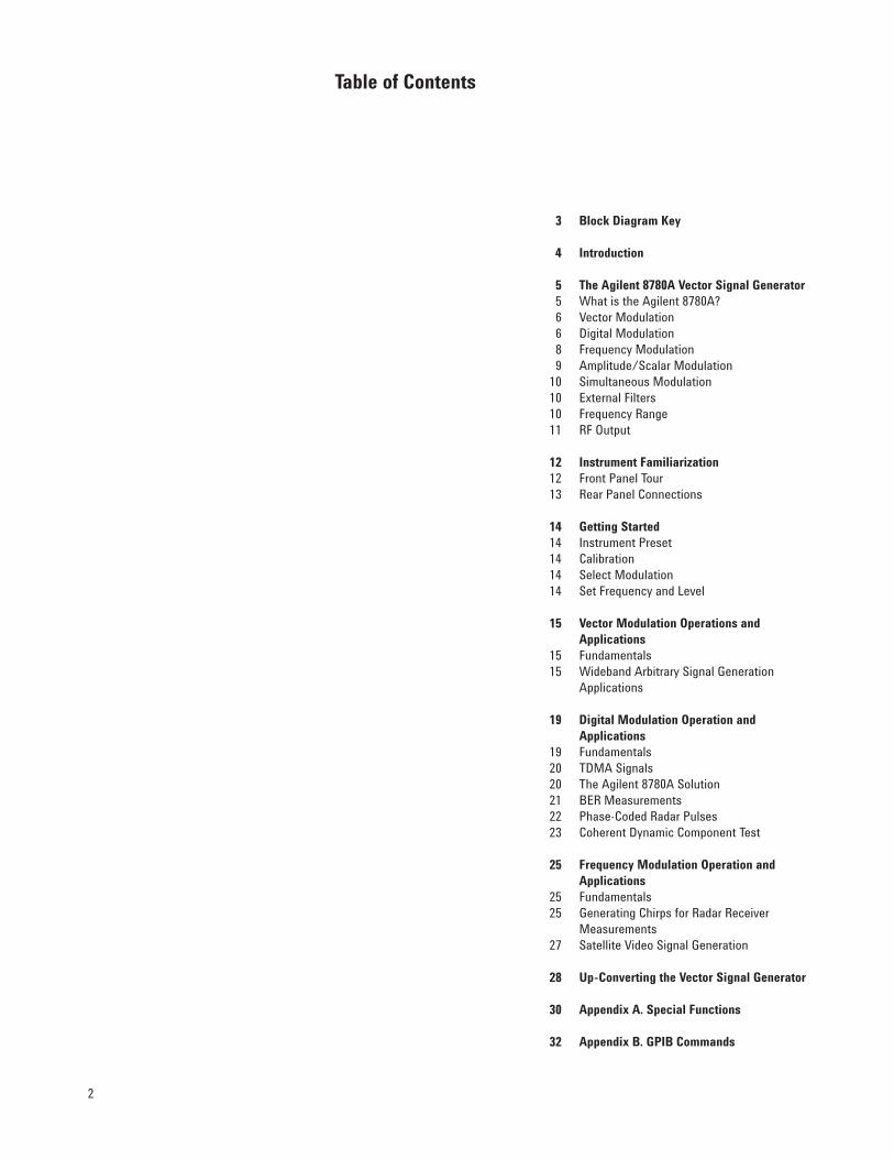
Block Diagram Key
Introduction
The Agilent 8780A Vector Signal GeneratorWhat is the Agilent 8780A?Vector ModulationDigital ModulationFrequency ModulationAmplitude/Scalar ModulationSimultaneous ModulationExternal FiltersFrequency RangeRF Output
Instrument FamiliarizationFront Panel TourRear Panel Connections
Getting StartedInstrument PresetCalibrationSelect ModulationSet Frequency and Level
Vector Modulation Operations andApplicationsFundamentalsWideband Arbitrary Signal GenerationApplications
Digital Modulation Operation andApplicationsFundamentalsTDMA SignalsThe Agilent 8780A SolutionBER MeasurementsPhase-Coded Radar PulsesCoherent Dynamic Component Test
Frequency Modulation Operation andApplicationsFundamentalsGenerating Chirps for Radar ReceiverMeasurementsSatellite Video Signal Generation
Up-Converting the Vector Signal Generator
Appendix A. Special Functions
Appendix B. GPIB Commands
Table of Contents

3
Agilent 8780A Vector Signal Generator
Agilent 8980A Vector Analyzer
Agilent 8770A Arbitrary Waveform Synthesizer
Agilent 8671B Synthesized Signal Generator
Agilent 8656B Synthesized Signal Generator
Agilent 8165A Programmable Signal Source
Agilent 8116A Pulse/Function Generator
Agilent 3762A Data Generator
Agilent 3708A Noise and Interference Test Set
Agilent 9000 Series Controller
Block Diagram Key

4
This Product Note contains detailedinformation about the use and appli-cation of the Agilent Technologies8780A Vector Signal Generator.
Being sure that a product like the vec-tor signal generator meets your meas-urement needs sometimes requiresmore information than what’s in adata sheet or brochure. This docu-ment describes important applicationconcerns and should help you use thevector signal generator to satisfy yourmeasurement requirements.
The first two sections describe thevector signal generator’s main featuresand familiarize you with the controlsand connectors on the front and rearpanels. Sections 3, 4, and 5 describebasic operation and application of thevector, digital, and FM modulationmodes respectively. The Appendixcontains supplementary informationabout the instrument’s special func-tions and GPIB commands.
While this Product Note covers thegeneral use and application of the8780A Vector Signal Generator, thereare other publications that may helpto address the measurement needs ofspecific systems. The following publi-cations are available from yourAgilent field engineer.
Product Note 8980A-1 IntroductoryOperating Guide to the Agilent 8980AVector Analyzer. The vector analyzer isa companion product to the vector sig-nal generator, and they are often usedtogether in measurement systems. The8980A Product Note contains informa-tion necessary to understand its useand evaluate its suitability for specificmeasurements.
AN 343-1 Measurement ApplicationsIn Digital Microwave Radio. Digitalmicrowave radios (DMRs) are increas-ingly chosen for both satellite andterrestrial applications. ApplicationNote 343-1 outlines some of the meas-urements and test procedures criticalto measuring the analog signals inDMR systems. It provides a goodstarting point for the engineer ortechnician called upon to designmeasurements for these applications.
AN 343-3 Coherent Pulsed Tests ofRadar and Electronic WarfareSystems. Almost all radars and elec-tronic warfare equipment now coher-ently transmit and detect their sig-nals. This Application Note describesmethods of testing the microwave andIF portions of radar and EW equip-ment using a vector measurementsystem.
I·Q Tutor: The Agilent DigitalCommunications Tutorial. Sometimesit’s best to start at the beginning. I·QTutor is a tutorial manual and comput-er program that simulates many of thesignals in real digital microwave radiosto help develop an understanding ofthe fundamental concepts of digitalcommunication. The computer programruns on IBM-PC™ compatibles (HP11736B), and HP 9000 series models216, 217, 236, and 236C (HP 11736A).
If your particular application is notcovered by one of the documents list-ed, consult your Agilent field engi-neer for the latest list of product andapplication notes.
Introduction

5
What Is The Agilent 8780A?The Agilent 8780A Vector Signal Gener-ator is a 10 MHz to 3 GHz synthesizedmicrowave signal generator with ex-ceptional modulation capabilities. Itsname, “vector”, comes from the way itachieves its modulation: by using a“vector” or I/Q modulator. The vectormodulator gives the generator modu-lation bandwidths much wider thanthose previously available. In additionto vector modulation, the vector signalgenerator can do many phase shiftkeyed (PSK) and quadrature amplitudemodulations (QAM) using its digitalinputs. This simplifies generation ofdigital microwave radio (DMR), phase-coded radar and other digitally modu-lated signals. The 8780A can also befrequency or amplitude modulatedwith analog signals.
Vector modulation allows arbitraryphase and amplitude modulation withbandwidths up to 700 MHz peak-to-peak. The modulation capability iscomplemented by a coherent carrieravailable at the rear panel. This refer-ence signal simplifies demodulation andenables pulsed phase measurements.
For convenient generation of commonmodulation formats, the 8780A hasdigital inputs for switching betweenpreset generator output phase-amplitude states.
The 8780A also provides very widebandlinear frequency modulation. FM devia-tion is specified to 50 MHz p-p at upto 12 MHz rates. Simultaneous modu-lations can simulate radar chirps andantenna scan patterns.
The Agilent 8780A Vector Signal Generator
Simplified vector signal generator block diagram

6
Vector ModulationVector modulation represents a signif-icant departure from traditional signalgenerator modulation techniques. Ini-tially used in communication systemsbecause of its ability to efficiently uti-lize transmission bandwidth, vectormodulation now provides increasedmodulation bandwidths in a microwavesignal generator.
Vector modulation, or I/Q modulationas it is sometimes called, is a methodof modulating a carrier with two base-band signals called the in-phase (I) andquadrature-phase (Q) components. TheI and Q signals effectively “move” thecarrier signal (or vector) about the I/Qplane. In the I/Q plane, the phase of asignal is the angle of its vector withrespect to the I axis, and the magnitudeis the length of the vector from the ori-gin. The diagram below illustrates therelationship of the generator’s outputphase and amplitude to given I and Qvoltages.
Vector modulation is the most wide-band arbitrary way of using the Agilent8780A. The vector inputs have band-widths of 350 MHz and can be used togenerate phase, amplitude, and fre-quency modulation. These capabilitiesare explained in more detail inChapter 4—Vector ModulationOperation and Applications.
Digital ModulationThe digital inputs of the 8780A VectorSignal Generator provide a conven-ient way of generating phase-shift-keyed and quadrature amplitudemodulations. Built-in mapping cir-cuitry converts digital inputs intoanalog I and Q voltages to drive thevector modulator and generate thefollowing modulations: BPSK, QPSK,8PSK, 16QAM, and 64QAM (withOption 064). Besides these standardmodulations, the digital modulationcircuitry allows several variationswhich are particularly valuable inperforming receiver tests.
There are six digital inputs on thestandard vector signal generator; fourdata inputs, and two clock inputs1.These inputs are the modulationsource lines for all digital modula-tions. The data lines determine whichof the I/Q (or phase-amplitude) statesthe generator will output. Changingthe digital signals at these inputschanges the phase and amplitude ofthe output and generates the desiredQAM or PSK modulation.
1. Option 064 adds one data input and deletes one ofthe clocks.

7
Vector signal generator standard modula-tions; Option 064 adds 64QAM.
The clock inputs can be used to latchthe analog I and Q voltages into themodulator. Although modulation canbe done asynchronously (i.e., without aclock input), the two clock inputs canbe used to latch I and Q signals inde-pendently, or one clock can be used tolatch both I and Q. Synchronous oper-ation ensures data symmetry and fastrise times at high clock rates (>50 MHz).At lower rates, synchronous operationmay be used to clean up data asymme-try, remove slow rise times, or providestaggered modulations.
In addition to the preset modulations(BPSK, QPSK, 8PSK and 16QAM), the8780A can modulate between any twouser-defined states. TWO STATE usesa digital input line to switch the out-put back and forth between two user-specified I/Q or phase-amplitudestates.
BURST, when used by itself, is analo-gous to pulse modulation on tradi-tional generators. It simply switchesthe generator’s CW output on and offas controlled by one of the digital inputlines. The on/off ratio specified forBURST operation is 50 dB; typicalperformance is 55 dB. The on/off ratiois a function of how well the vectormodulator is calibrated, and will bebest after using the calibration key.
When BURST mode is used with anoth-er modulation like 8PSK, the BURSTline gates the output of the generator.This facilitates easy simulation oftime domain multiple access (TDMA)bursts, Barker coded radar signals,and other discontinuous signals.
The basic modulations such as BPSKand QPSK can be modified to suit theneeds of your particular system or tostress your receiver. One of the simplestways that a modulation can be modi-fied is by selectively attenuating themodulation format in the I direction.This is done by selecting the I<Qmode and can be used with any of thevector signal generator modulations.
Two-state modulation
Burst modulations for TDMA simulationand phase-coded pulses
I < Q for circuit stress testing and unbal-anced modulations
8
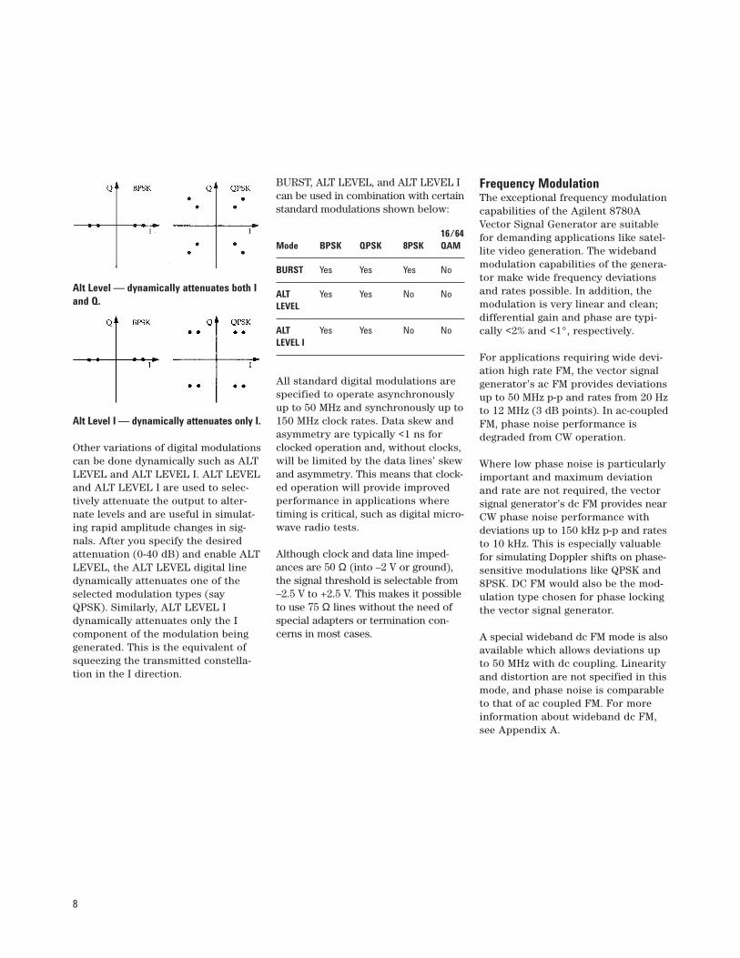
Alt Level — dynamically attenuates both Iand Q.
Alt Level I — dynamically attenuates only I.
Other variations of digital modulationscan be done dynamically such as ALTLEVEL and ALT LEVEL I. ALT LEVELand ALT LEVEL I are used to selec-tively attenuate the output to alter-nate levels and are useful in simulat-ing rapid amplitude changes in sig-nals. After you specify the desiredattenuation (0-40 dB) and enable ALTLEVEL, the ALT LEVEL digital linedynamically attenuates one of theselected modulation types (sayQPSK). Similarly, ALT LEVEL Idynamically attenuates only the Icomponent of the modulation beinggenerated. This is the equivalent ofsqueezing the transmitted constella-tion in the I direction.
BURST, ALT LEVEL, and ALT LEVEL Ican be used in combination with certainstandard modulations shown below:
16/64Mode BPSK QPSK 8PSK QAM
BURST Yes Yes Yes No
ALT Yes Yes No NoLEVEL
ALT Yes Yes No NoLEVEL I
All standard digital modulations arespecified to operate asynchronouslyup to 50 MHz and synchronously up to150 MHz clock rates. Data skew andasymmetry are typically <1 ns forclocked operation and, without clocks,will be limited by the data lines’ skewand asymmetry. This means that clock-ed operation will provide improvedperformance in applications wheretiming is critical, such as digital micro-wave radio tests.
Although clock and data line imped-ances are 50 Ω (into –2 V or ground),the signal threshold is selectable from–2.5 V to +2.5 V. This makes it possibleto use 75 Ω lines without the need ofspecial adapters or termination con-cerns in most cases.
Frequency ModulationThe exceptional frequency modulationcapabilities of the Agilent 8780AVector Signal Generator are suitablefor demanding applications like satel-lite video generation. The widebandmodulation capabilities of the genera-tor make wide frequency deviationsand rates possible. In addition, themodulation is very linear and clean;differential gain and phase are typi-cally <2% and <1°, respectively.
For applications requiring wide devi-ation high rate FM, the vector signalgenerator’s ac FM provides deviationsup to 50 MHz p-p and rates from 20 Hzto 12 MHz (3 dB points). In ac-coupledFM, phase noise performance isdegraded from CW operation.
Where low phase noise is particularlyimportant and maximum deviationand rate are not required, the vectorsignal generator’s dc FM provides nearCW phase noise performance withdeviations up to 150 kHz p-p and ratesto 10 kHz. This is especially valuablefor simulating Doppler shifts on phase-sensitive modulations like QPSK and8PSK. DC FM would also be the mod-ulation type chosen for phase lockingthe vector signal generator.
A special wideband dc FM mode is alsoavailable which allows deviations upto 50 MHz with dc coupling. Linearityand distortion are not specified in thismode, and phase noise is comparableto that of ac coupled FM. For moreinformation about wideband dc FM,see Appendix A.
9
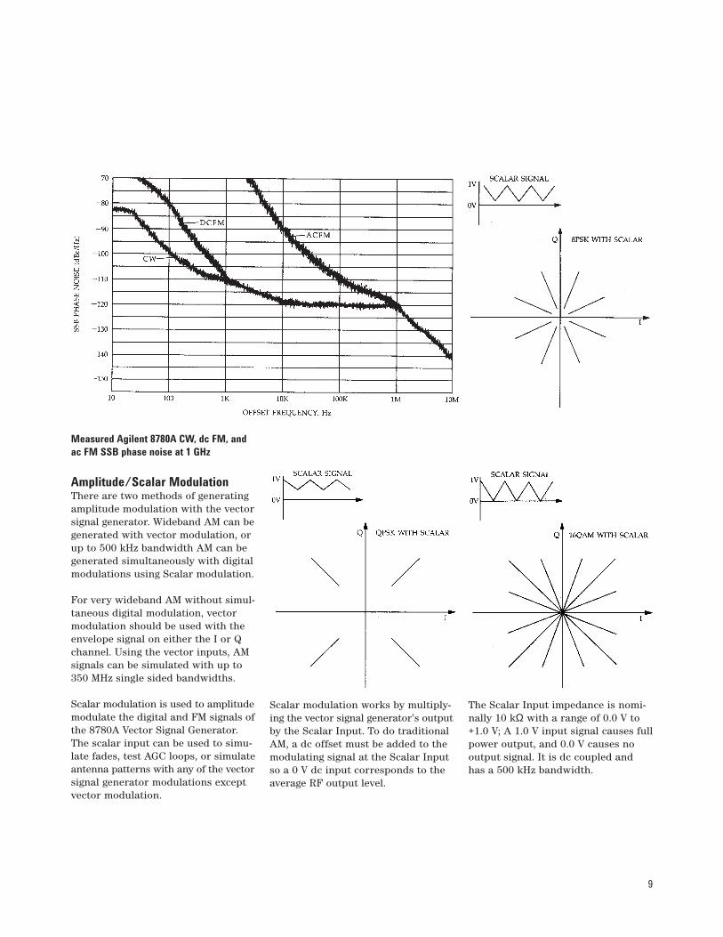
Measured Agilent 8780A CW, dc FM, andac FM SSB phase noise at 1 GHz
Amplitude/Scalar ModulationThere are two methods of generatingamplitude modulation with the vectorsignal generator. Wideband AM can begenerated with vector modulation, orup to 500 kHz bandwidth AM can begenerated simultaneously with digitalmodulations using Scalar modulation.
For very wideband AM without simul-taneous digital modulation, vectormodulation should be used with theenvelope signal on either the I or Qchannel. Using the vector inputs, AMsignals can be simulated with up to350 MHz single sided bandwidths.
Scalar modulation is used to amplitudemodulate the digital and FM signals ofthe 8780A Vector Signal Generator.The scalar input can be used to simu-late fades, test AGC loops, or simulateantenna patterns with any of the vectorsignal generator modulations exceptvector modulation.
Scalar modulation works by multiply-ing the vector signal generator’s outputby the Scalar Input. To do traditionalAM, a dc offset must be added to themodulating signal at the Scalar Inputso a 0 V dc input corresponds to theaverage RF output level.
The Scalar Input impedance is nomi-nally 10 kΩ with a range of 0.0 V to+1.0 V; A 1.0 V input signal causes fullpower output, and 0.0 V causes nooutput signal. It is dc coupled andhas a 500 kHz bandwidth.
10
Simultaneous ModulationIt is often advantageous to be able tocombine various modulations to cre-ate signals which either better repre-sent the real world or help stressdevices being tested. Because of this,the Agilent 8780A Vector SignalGenerator does several differentsimultaneous modulations. The per-missible combinations are shownbelow:
Modulation Digital Scalar FM Vector
Digital — Yes Yes No
Scalar Yes — Yes No
FM Yes Yes — Yes
Vector No No Yes —
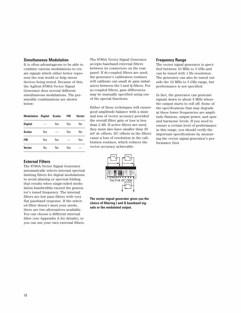
External FiltersThe 8780A Vector Signal Generatorautomatically selects internal spectrallimiting filters for digital modulationsto avoid aliasing or spectral foldingthat results when single-sided modu-lation bandwidths exceed the genera-tor’s tuned frequency. The internalfilters are low pass filters with veryflat passband response. If the select-ed filter doesn’t meet your needs,there are two alternatives available.You can choose a different internalfilter (see Appendix A for details), oryou can use your own external filters.
The 8780A Vector Signal Generatoraccepts baseband external filtersbetween its connectors on the rearpanel. If dc-coupled filters are used,the generator’s calibration routineswill calibrate out small dc gain imbal-ances between the I and Q filters. Forac-coupled filters, gain differencesmay be manually specified using oneof the special functions.
Either of these techniques will ensuregood amplitude balance with a mini-mal loss of vector accuracy providedthe overall filter gain or loss is lessthan 2 dB. If active filters are used,they must also have smaller than 20mV dc offsets. DC offsets in the filterscause a loss of resolution in the cali-bration routines, which reduces thevector accuracy achievable.
The vector signal generator gives you thechoice of filtering I and Q baseband sig-nals or the modulated output.
Frequency RangeThe vector signal generator is speci-fied between 10 MHz to 3 GHz andcan be tuned with 1 Hz resolution.The generator can also be tuned out-side the 10 MHz to 3 GHz range, butperformance is not specified.
In fact, the generator can generatesignals down to about 4 MHz wherethe output starts to roll off. Some ofthe specifications that may degradeat these lower frequencies are ampli-tude flatness, output power, and spurand harmonic levels. If you need toensure a certain level of performancein this range, you should verify theimportant specifications by measur-ing the vector signal generator’s per-formance first.

11
RF OutputThe RF Output of the Agilent vectorsignal generator has a wide dynamicrange and achieves very good flatnessthrough the use of software correctiontables. Output level is controlled fromthe front panel keypad or knob and canbe varied from +12 dBm to –110 dBmin 0.1 dBm steps. Maximum availableoutput level is specified to be +10 dBmfor 10 MHz to 2.5 GHz and +4 dBm to3 GHz. When output level is set usingthe front panel keys or knob, the instru-ment automatically selects the stepattenuator and vernier settings neces-sary for the desired level. In somecases, particularly when testing phaselocked systems, the automatic switch-ing of step attenuator settings mayinterfere with the measurement. Thevector signal generator has an extend-ed vernier mode for these situations.
In the extended vernier mode thestep attenuator doesn’t switch andthe level vernier range is extended.With the "Lock Step, Extend Range"special function, the RF output leveltypically can be tuned over a 20 dBrange (from roughly 10 dB below thelow attenuator switch point to justover the high attenuator switchpoint). This is wide enough to provideample tuning range for receiver sensi-tivity tests and similar measure-ments. Extended vernier operation isnot specified, and at the extremes ofthe vernier range, the vector signalgenerator’s vector accuracy maydegrade slightly.
Agilent 8780A level always corresponds tothe maximum modulation states.
For vector modulations and digitalmodulations, the definition of outputlevel must be carefully understood.The level set using RF Output levelcontrols always refers to the magni-tude of the largest state in thesemodes. The maximum level corre-sponds to a vector of magnitude 0.5 Vat the vector inputs, which is themagnitude of the largest state of thedigital modulation selected. Forexample, if 16QAM modulation isselected, and the RF Output level is–4.0 dBm, then the magnitude of theoutermost states of the 16QAM con-stellation will be –4.0 dBm. Similarly,if vector modulation is selected, andthe RF Output level is –4.0 dBm, thenthe output will only be –4.0 dBm foran I input of +0.5 V and no Q input,or some other vector of the samemagnitude.

12
Front Panel Tour1. The Display—LCD display panelshows frequency, amplitude, FM sen-sitivity, modulation type, easy-to-readerror messages, and warnings. It alsodisplays prompts for various instru-ment set-up commands.
2. GPIB Status—LEDs indicate statusof GPIB operation. LCL key returnsthe Agilent 8780A from remote to frontpanel operation unless local lockout isprogrammed. LCL is also used to dis-play the GPIB address. As long as thiskey is held down the GPIB address willbe displayed on the left display.
3. Calibration—The CAL key calibratesthe instrument’s baseband vector modu-lator, FM modulator, and output level.Periodic calibration is recommendedto compensate for component driftwith temperature and time.
4. Instrument State—This group of keyscontrols many of the initial setup con-ditions of the instrument. SAVE andRECALL can be used to save a set-upor to recall it later. Some of the set-upparameters that can be controlled arethe data threshold and number ofclocks for digital modulation, theinversion of digital lines, and thepresence of external filters.
Pressing the MSG key in this groupshows error and warning messageson the display. When an error orwarning condition occurs, the LED onthis key will light and stay lit untilthe key is pressed to examine themessage, or until the error conditionis changed. If more than one messageapplies, successive ones can be readby repeatedly pressing the MSG key.
5. Entry—The keys and knob in thissection set signal frequency, level, FMdeviation, ALT LEVEL, ALT LEVEL I,I<Q, and TWO STATE modulations.Parameters to be changed are select-ed with one of the SET keys on theleft of the section. The parameter isthen displayed and can be changed bytyping in a new value with the key-pad, using the up and down arrows toincrement and decrement, or usingthe knob. If the keypad is used, theunits keys on the right of the sectionterminate the entry.
6. Digital Inputs—There are six 50 Ωdigital inputs that can be used to domany different quadrature-amplitudeand phase-shift- keyed modulations.There are four data and two clocklines2. Next to each BNC connectorare two LEDs to indicate which linesare active and which lines are invert-ed. Line terminations are –2 V forECL levels and ground for all others.
7. FM Input—This is the frequencymodulation input line and it has a 50 Ωimpedance. Full scale modulation isobtained with +0.5 V to –0.5 V for dcFM and 1 Vpp for ac FM.
Note that this is the only analog mod-ulation input that can be inverted.This allows the frequency modulatedspectrum to be easily reversed. AnLED also indicates the line is activewhen FM is selected.
8. Scalar Input—The Scalar input hasa nominal impedance of 10 kΩ and itsfull scale range is 0 V to +1 V with 0 Vcorresponding to no output. Scalarfrequency response is dc to 500 kHz.
9. Vector Input—The Vector Inputlines are direct I and Q inputs to thevector modulator. Full scale I and Qvoltages are –0.5 V to +0.5 V into 50 Ω;however, vector accuracy is only spec-ified for vectors with magnitudes lessthan 0.5 V (the square root of the sumof the squares of I and Q voltages mustbe less than 0.5 V). I and Q bandwidthsare dc to 350 MHz.
2. Option 064 adds one data input and deletes one ofthe clocks.
Instrument Familiarization
13
10. RF Output—This is the 8780AVector Signal Generator’s primaryoutput. It is the test signal generatedwith all modulation, level, and fre-quency control. For demodulationpurposes, a coherent output, whichhas no modulation except for FM, isprovided on the rear panel.
The Phase Bump special function canbe used to shift the RF Output andCoherent Carrier phase with respectto the 10 MHz frequency reference.This makes it possible to change thevector signal generator’s phase withrespect to another synthesizer. PhaseBump does not change the phase ofthe Coherent Carrier with respect tothe RF Output.
11. Output Control—This section ofthe front panel toggles different mod-ulations and the RF output on and off.LEDs in the keys indicate which mod-ulations are on and whether the RFoutput is enabled. Simultaneous mod-ulations can be selected provided theyare compatible. For example, QPSKand Scalar may both be selected, but16QAM and Burst may not (sincethere aren’t enough data lines). Anymodulation can be turned off in thesame way that is was turned on—bypressing that modulation key.
The RF OUT ON key toggles theCoherent Carrier on and off alongwith the RF output.
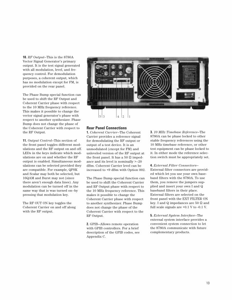
Rear Panel Connections 1. Coherent Carrier—The CoherentCarrier provides a reference signalfor demodulating the RF output oroutput of a test device. It is anunmodulated (except for FM) andunleveled version of the RF output atthe front panel. It has a 50 Ω imped-ance and its level is nominally >–20dBm. Coherent Carrier level can beincreased to +9 dBm with Option 002.
The Phase Bump special function canbe used to shift the Coherent Carrierand RF Output phase with respect tothe 10 MHz frequency reference. Thismakes it possible to change theCoherent Carrier phase with respectto another synthesizer. Phase Bumpdoes not change the phase of theCoherent Carrier with respect to theRF Output.
2. GPIB—Allows remote operationwith GPIB controllers. For a briefdescription of the GPIB codes, seeAppendix C.
3. 10 MHz Timebase Reference—The8780A can be phase locked to otherstable frequency references using the10 MHz timebase reference, or othertest equipment can be phase locked toit. In either mode the reference selec-tion switch must be appropriately set.
4. External Filter Connectors—External filter connectors are provid-ed which let you use your own base-band filters with the 8780A. To usethem, you remove the jumpers sup-plied and insert your own I and Qbaseband filters in their place.External filters are selected on thefront panel with the EXT FILTER ONkey. I and Q impedances are 50 Ω andfull scale signals are +0.1 V to -0.1 V.
5. External System Interface—Theexternal system interface provides aconvenient system connection to letthe 8780A communicate with futurecomplementary products.

14
This chapter describes the basic oper-ation of the vector signal generator. Itcovers calibration and the selection ofmodulation, frequency, output level,and other parameters which you willhave to change for general operation.The details of operating different mod-ulations are covered in the chaptersthat follow.
Instrument PresetTo establish a known setup prior toentering new data, press the greenINSTR PRESET key. Preset sets the8780A to the following configuration:
Modulation: Off Frequency: 70 MHz Amplitude: -110 dBm RF Out: On DC FM: Off Special Functions: Off Digital Lines: Not Inverted Clock and Data: ECL Levels Knob: Off No External Clocks No External Filters
CalibrationThe vector signal generator should becalibrated by pressing the CAL buttonbefore using the instrument. The cali-bration routine makes several criticaladjustments to the vector modulator,digital mapping, and FM circuits.Aside from doing an initial adjust-ment of the modulation components,calibration should also be used toremove component drift that occursduring warm-up.
Select ModulationOnce preset and calibrated, the Agilent8780A is ready to generate the desiredmodulation.
To select vector modulation, press theVECTOR ON button. The VECTOR ONLED and the LEDs next to the I and Qinputs will light, indicating that vectormodulation has been selected.
To select digital modulations, press thedigital modulation key that correspondsto the basic modulation desired (BPSK,QPSK, 8PSK, or 16QAM). If a modifiedmodulation is desired, select the secondmodulation also. The output ON/OFFsection of the keyboard will indicatethe modulation(s) selected by lightingthe LEDs in the appropriate keys. Also,the LEDs next to the required digitalinputs will light.
To select frequency modulation, pressthe FM ON button. If dc FM is desired(usually in a phase locked application),press the DC COUP FM button also.
Set Frequency and LevelUse either the SET FREQUENCY orSET LEVEL keys to set your desiredoperating frequency or RF outputlevel. The display will indicate whichhas been selected by showing a cursorunder one digit of either the level orfrequency.
You can change the value selected bytyping a new value using the keypad,increasing and decreasing the valuewith the up and down arrows, or byusing the knob. If the keypad is used,the entry must be terminated withone of the units keys at the right ofthe entry section. If using the incre-ment/decrement method, the SETINCR key sets the amount that isadded or subtracted each time the upor down arrow is pressed.
To use the knob, first turn it on bypressing the KNOB button. The knobbutton LED shows the knob is active.The knob always increments or decre-ments the digit of the value beingentered that is directly above the cur-sor. The cursor is moved by using theleft and right arrow keys found justabove the knob.
Getting Started
15
FundamentalsThe vector modulation in the 8780Amakes arbitrary phase and amplitudemodulation possible with up to 700 MHzbandwidths. This is valuable in alarge number of applications wherestandard modulation techniques areinsufficient. Variable rise time pulses,high complexity digital modulations,some spreadspectrum communica-tions, and other non-standard modu-lations can all be accomplished withvector modulation on the 8780AVector Signal Generator.
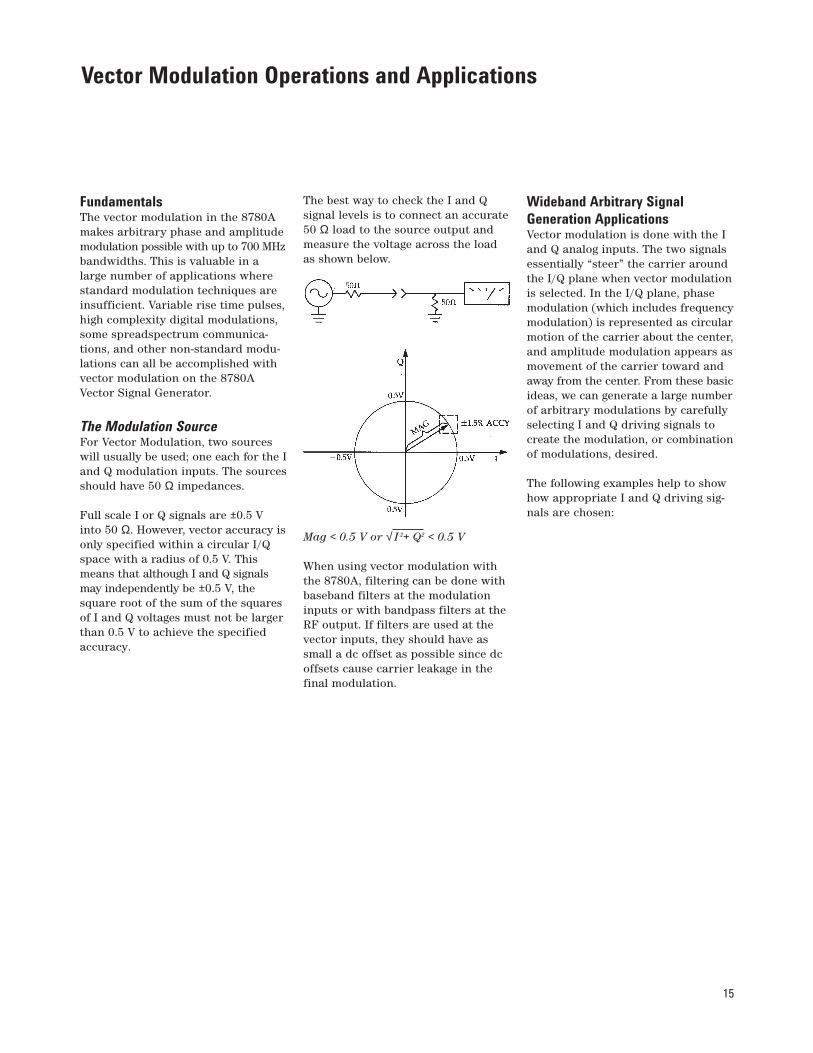
The Modulation SourceFor Vector Modulation, two sourceswill usually be used; one each for the Iand Q modulation inputs. The sourcesshould have 50 Ω impedances.
Full scale I or Q signals are ±0.5 Vinto 50 Ω. However, vector accuracy isonly specified within a circular I/Qspace with a radius of 0.5 V. Thismeans that although I and Q signalsmay independently be ±0.5 V, thesquare root of the sum of the squaresof I and Q voltages must not be largerthan 0.5 V to achieve the specifiedaccuracy.
The best way to check the I and Q signal levels is to connect an accurate 50 Ω load to the source output andmeasure the voltage across the loadas shown below.
Mag < 0.5 V or √ I 2+ Q2 < 0.5 V
When using vector modulation withthe 8780A, filtering can be done withbaseband filters at the modulationinputs or with bandpass filters at theRF output. If filters are used at thevector inputs, they should have assmall a dc offset as possible since dcoffsets cause carrier leakage in thefinal modulation.
Wideband Arbitrary SignalGeneration ApplicationsVector modulation is done with the Iand Q analog inputs. The two signalsessentially “steer” the carrier aroundthe I/Q plane when vector modulationis selected. In the I/Q plane, phasemodulation (which includes frequencymodulation) is represented as circularmotion of the carrier about the center,and amplitude modulation appears asmovement of the carrier toward andaway from the center. From these basicideas, we can generate a large numberof arbitrary modulations by carefullyselecting I and Q driving signals tocreate the modulation, or combinationof modulations, desired.
The following examples help to showhow appropriate I and Q driving sig-nals are chosen:
Vector Modulation Operations and Applications
16
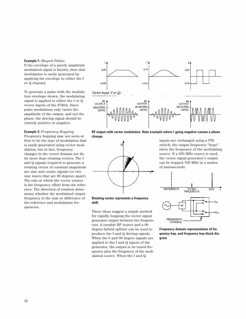
Example 1: Shaped Pulses If the envelope of a purely amplitudemodulated signal is known, then thatmodulation is easily generated byapplying the envelope to either the Ior Q channel.
To generate a pulse with the modula-tion envelope shown, the modulatingsignal is applied to either the I or Qvector inputs of the 8780A. Sincepulse modulation only varies theamplitude of the output, and not thephase, the driving signal should beentirely positive or negative.
Example 2: Frequency HoppingFrequency hopping may not seem atfirst to be the type of modulation thatis easily generated using vector mod-ulation, but in fact, frequencychanges in the vector domain are lit-tle more than rotating vectors. The Iand Q signals required to generate arotating vector of constant magnitudeare sine and cosine signals (or twosine waves that are 90 degrees apart).The rate at which the vector rotatesis the frequency offset from the refer-ence. The direction of rotation deter-mines whether the modulated outputfrequency is the sum or difference ofthe reference and modulation fre-quencies.
Rotating vector represents a frequencyshift
These ideas suggest a simple methodfor rapidly hopping the vector signalgenerator output between two frequen-cies. A tunable RF source and a 90degree hybrid splitter can be used toproduce the I and Q driving signals.When the 0 and 90 degree signals areapplied to the I and Q inputs of thegenerator, the output is its tuned fre-quency plus the frequency of the mod-ulation source. When the I and Q
inputs are exchanged using a PINswitch, the output frequency “hops”twice the frequency of the modulatingsource. If a 350 MHz source is used,the vector signal generator’s outputcan be hopped 700 MHz in a matterof nanoseconds.
Frequency domain representation of fre-quency hop, and frequency hop block dia-gram
RF output with vector modulation. Note example where I going negative causes a phasechange.

17
Example 3: MSK Signals Minimum shift keying (MSK) is oftenused in satellite communications andother systems where nonlinear ampli-fication is prevalent. MSK signals arefrequency shift keyed (FSK) signalswhose shift-frequency is a function ofthe clock rate of the data to be sent.The frequency shift is plus and minusone fourth the clock rate of the data.The generation of MSK signals with thevector signal generator is very similarto the frequency hopped signal justdiscussed.
If we use the same approach that wastaken in the frequency hopped example,and use the data to switch the I and Qchannels, the most important remain-ing concern is the precise generation ofthe shift frequency. This can easily bedone by dividing the clock frequencyby four using digital circuits. Oncedivided, the square wave output canbe filtered to provide the sine waveneeded for the frequency shift. Usingthis technique and good components,MSK can be done using the vector sig-nal generator at rates up to severalhundred MHz.
MSK spectrum
MSK vector diagram
Block diagram for generating MSK
Example 4: Arbitrary Signals—TheGeneral Case Almost any modulation can be simu-lated with the vector inputs of the8780A, provided the modulation isdefined in amplitude and phase or in terms of I and Q.
One way of generating a very widerange of I and Q driving signals is touse digital-to-analog converters (DACs).Using DACs allows I and Q drivingsignals to be generated from digital
signal definitions stored in memory.Theoretically, any conceivable type ofmodulation known could be generatedusing this basic technique.
If DACs are used to drive the I and Qvector inputs, the maximum theoreti-cal IF modulation bandwidth will beequal to the clock rate of the DAC,provided it doesn’t exceed the capa-bilities of the vector signal generator.Usually a clock rate twice the signalbandwidth is required to reconstructa signal, but the vector modulationtechnique lets us use two lower ratesources to generate a signal with abandwidth equal to the clock rate.Another way of putting it is that themodulation bandwidth is twice whatit would be for a simple up-conver-sion and filter. For example, if twoDACs with a maximum clock rate of50 MHz are available, modulationscan be simulated with bandwidths upto 50 MHz.
In the DAC application illustrated, two50-MHz DACs are used to generate Iand Q driving signals with 25-MHzbandwidths. Filters are used to elimi-nate the higher frequency componentsof the DAC outputs. The bandwidth ofthe vector signal generator output is50 MHz since it combines the two 25 MHz bandwidths in the modula-tion process.
The vector signal generator’s RF output bandwidth is twice the bandwidth of the I and Qsignals when generating arbitrary modulations.
18
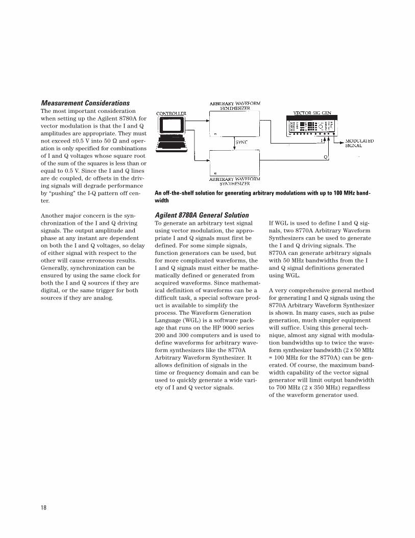
Measurement ConsiderationsThe most important considerationwhen setting up the Agilent 8780A forvector modulation is that the I and Qamplitudes are appropriate. They mustnot exceed ±0.5 V into 50 Ω and oper-ation is only specified for combinationsof I and Q voltages whose square rootof the sum of the squares is less than orequal to 0.5 V. Since the I and Q linesare dc coupled, dc offsets in the driv-ing signals will degrade performanceby “pushing” the I-Q pattern off cen-ter.
Another major concern is the syn-chronization of the I and Q drivingsignals. The output amplitude andphase at any instant are dependenton both the I and Q voltages, so delayof either signal with respect to theother will cause erroneous results.Generally, synchronization can beensured by using the same clock forboth the I and Q sources if they aredigital, or the same trigger for bothsources if they are analog.
Agilent 8780A General SolutionTo generate an arbitrary test signalusing vector modulation, the appro-priate I and Q signals must first bedefined. For some simple signals,function generators can be used, butfor more complicated waveforms, theI and Q signals must either be mathe-matically defined or generated fromacquired waveforms. Since mathemat-ical definition of waveforms can be adifficult task, a special software prod-uct is available to simplify theprocess. The Waveform GenerationLanguage (WGL) is a software pack-age that runs on the HP 9000 series200 and 300 computers and is used todefine waveforms for arbitrary wave-form synthesizers like the 8770AArbitrary Waveform Synthesizer. Itallows definition of signals in thetime or frequency domain and can beused to quickly generate a wide vari-ety of I and Q vector signals.
If WGL is used to define I and Q sig-nals, two 8770A Arbitrary WaveformSynthesizers can be used to generatethe I and Q driving signals. The8770A can generate arbitrary signalswith 50 MHz bandwidths from the Iand Q signal definitions generatedusing WGL.
A very comprehensive general methodfor generating I and Q signals using the8770A Arbitrary Waveform Synthesizeris shown. In many cases, such as pulsegeneration, much simpler equipmentwill suffice. Using this general tech-nique, almost any signal with modula-tion bandwidths up to twice the wave-form synthesizer bandwidth (2 x 50 MHz= 100 MHz for the 8770A) can be gen-erated. Of course, the maximum band-width capability of the vector signalgenerator will limit output bandwidthto 700 MHz (2 x 350 MHz) regardlessof the waveform generator used.
An off-the-shelf solution for generating arbitrary modulations with up to 100 MHz band-width

19
FundamentalsDigital modulation in the 8780Amakes the generation of a variety ofquadrature amplitude and phase shiftkeyed modulations easy. Digital signalsat the vector signal generator’s inputcontrol the phase and amplitude of theoutput signal making the generationof modulated test signals as easy asconnecting the cables. Some of theapplications where digital modulationwill be appreciated are terrestrial andsatellite digital communications as wellas in phase-coded Radar/EW systems.
The Modulation SourceFor digital modulations, the mostcommon modulation source will be a data generator. Depending on themodulation chosen, you may needsome additional hardware.
The digital inputs are essentially par-allel inputs to the I-Q modulation map.For BPSK, QPSK, 8PSK, and 16QAM,there will be 1, 2, 3, or 4 digital mod-ulation source lines required respec-tively. With Option 064 you have thechoice of providing 6 parallel inputsor one serial input at a six times rateand a word clock for 64QAM. All othermodulations still require parallel in-puts. Since data generators usuallyhave only one or two lines, we need away of driving more inputs for modu-lations requiring more than two inputs.
One way of getting more data lineswithout using additional data genera-tors is to use a serial-to-parallel con-verter. This takes one high data ratesignal and divides it into two, three, ormore lower rate data lines. If a clockis to be used, the clock must also bedivided down to the new data rate.
MappingFor the digitally modulated signal to bedecoded properly in a particular sys-tem it must have the correct mapping.
Digital modulation mapping refers tothe way the I-Q modulated states aredetermined from the digital word atthe map inputs (in the case of the8780A, the word at the digital inputlines). Because mapping conventionsvary, signals from similar systemsmay be incompatible. Because of this,the 8780A allows some flexibility inits mapping. By inverting, and/orswitching selected digital input lines,many different mappings are possible.
Consult the 8780A data sheet for spe-cific details regarding mapping.
Digital Modulation Operation and Applications
Some digital modulations require two or more parallel data lines, which can be derived using a serial-to-parallel converter.

20
TDMA SignalsThe vector signal generator can gen-erate signals typical of those used inmost time domain multiple access(TDMA) applications. When the vec-tor signal generator is used to gener-ate TDMA signals, many valuablereceiver and system tests are possi-ble. The wide dynamic range of thegenerator’s output facilitates simplereceiver sensitivity testing, and thegenerator dc FM can be used to simu-late Doppler shifts commonly seen insatellite communications.
Generating the correct modulation forTDMA signals involves two modula-tion processes: generation of theenvelope, and generation of the mod-ulation within the envelope or theframe of data. The pulse envelope canbe generated using the vector signalgenerator’s Burst digital modulationinput, and the modulation within thepulse can be generated using one ofthe generator’s digital modulations.Simultaneous burst operation ensuressynchronous burst and data transi-tions and the same envelope and datarise times. The BPSK, QPSK, and8PSK modulation modes of the gener-ator will cover the modulationrequirements of most TDMA signals.
Measurement ConsiderationsThe most important aspect of gener-ating TDMA signals, whether they befor terrestrial or satellite systems, isobtaining the correct modulation sig-nals to drive the modulation sourcelines. You will have to provide theright digital signals depending onyour modulation technique.
The signals consist of a Burst line,data lines (1 for BPSK, 2 for QPSK,and 3 for 8PSK), and possibly a clock.
Another possible concern in generat-ing TDMA signals is the pulse on/offratio. The vector signal generator’son/off ratio is specified to be > 50 dB(typically 55 dB). For greater dynam-ic range, an external pulse modulatorlike the 8730 series can be used, pro-viding an 80 dB on/off ratio with risetimes of 30 nanoseconds.
The Agilent 8780A SolutionAn example that addresses most ofthe major concerns of TDMA signalgeneration is shown below. Since thedata and burst lines vary with differ-ent applications, their generation isleft to the user. Once the data linesare connected correctly, and the mod-ulation types are selected, the vectorsignal generator is a versatile meas-urement source for TDMA communi-cations receivers and subsystems.
If only one vector signal generator isused, the basic modulation will haveto be modified to be representative oftypical TDMA signals. TDMA systemshave to quickly respond to changes intransmitter frequency, phase, leveland even clock rate. One vector signalgenerator can simulate some of thesechanges by using dc FM, ALT LEVELmodulation, and varying the dataclock frequency. These techniqueswill provide very rapid level switch-ing and fluctuations of the clock andradio frequencies, but are not exactlylike TDMA signals.
By using two generators, TDMA sig-nals can be more accurately simulat-ed. All of the variations in transmit-ters can be quickly simulated by sim-ply changing the generators’ frontpanel settings. Frequency variationscan be precisely selected and thephase of successive transmissionsfrom each signal generator will be thesame. If only phase discontinuity isimportant without any frequencychange, the Phase Bump special func-tion can be used to shift one genera-tor’s phase with respect to the otherin 0.1 degree increments.
There are several measurements pos-sible with the 8780A Vector SignalGenerator when generating TDMAsignals. Modulation errors can evenbe introduced for receiver testing. Byusing the vector signal generator’sCoherent Carrier, system componentscan be dynamically characterized usingtechniques described in the componenttest section of this chapter. BER meas-urements can also be made as describedin the next section.

21
BER Measurements ApplicationBit error rate (BER) tests are the mostdirect way to measure how well a digitalmicrowave radio is working. By meas-uring the number of errors received fora given number of transmitted bits, theradio’s ability to communicate informa-tion can be assessed. When the 8780AVector Signal Generator is used to gen-erate a benchmark digitally modulatedsignal, BER measurements can be usedto determine a receiver’s tolerance to awide variety of degradations includingquadrature error, Doppler frequencyshifts, amplitude imbalances, and fades.
Simulating "unbalanced" modulations ispossible with the 8780A I<Q modulation.
Measurement ConsiderationsAside from selecting your modulationformat on the 8780A, the most impor-tant consideration in making BER mea-surements is getting the Vector SignalGenerator’s modulation states for agiven digital input to match those ofthe radio to be tested. To set up the8780A to perform the correct mapping,the digital input lines may be invertedand switched with one another. Thedefault mappings are shown in thevector signal generator data sheet, andare easy to change by exchanging and/or inverting data lines.
Once the correct mapping and modu-lation types have been chosen, theremay still be some fine tuning requiredto make the 8780A modulation matchthe system under test. Some radios usemodulation formats which are rectan-gular instead of square. This just meansthat either the I or Q signal level is at-tenuated with respect to the other.These modulations may be generatedwith the 8780A by using SET I<Q toselect the appropriate attenuation forthe I signal. Once the I signal attenua-tion is chosen, the I<Q modulation keyis pressed to activate I<Q for the modu-lation selected.
The Agilent 8780A SolutionSetting up the 8780A Vector Signal Gen-erator for BER tests involves threebasic steps: generating the digitalinput signals, setting up the mapping,and connecting the BER detector. Themapping concerns are described earlierin this section, and the BER interfaceconcerns are addressed below. Degra-dations may also be added to the sig-nal to stress the receiver under test.
A serial-to-parallel converter may beneeded to increase the number of datalines available. For BER testing, theBER receiver will expect the initialserial line pattern, so a parallel toserial conversion will also be requiredat the receiver output. Sometimes thisis already done in the receiver, but ifit isn’t, a parallel-to-serial converterwill have to be built that complementsthe serial-to-parallel converter.
The clock input lines should not beneglected. Although the 8780A VectorSignal Generator can generate modu-lations without external clock inputs,a clock reduces the amount of jitterand data asymmetry in the modulat-ed signal and should be used whenev-er possible. When serial-to-parallelconverters are used, the clock mustalso be divided down with the datarate, and multiplied up in the case ofthe parallel-to-serial converter.

22
Many realistic tests can be done byfrequency modulating the test signalto simulate Doppler shifts, scalarmodulating to simulate fades, intro-ducing some amplitude imbalancewith I<Q, or testing carrier recoveryrange by varying the test signal fre-quency using dc FM. Other degrada-tions which may be introduced usingthe special functions include quadra-ture errors, and carrier leakage. (SeeAppendix A for details.) With theaddition of the Agilent 3708A Noiseand Interference Test Set, residualBER, BER vs. carrier to noise (C/N),and BER vs. carrier to interference(C/I) tests can all be easily made.
For more information about BERmeasurements refer to AN 343-1“Measurement Applications in DigitalMicrowave Radio” and “AdditiveWhite Noise and Interference Testingof Digital Radio Systems with Noiseof Finite Crest Factor” (Agilent litera-ture number 5954-2007).
Phase-Coded Radar Pulses Application The vector signal generator can gen-erate a wide range of phase-codedradar pulses including Barker codes.By using Burst and digital modula-tion simultaneously, several complexmodulations can be included withinpulses for testing radar receivers andother system components.
Example burst, data, and clock signals forgenerating a phase-coded pulse
Generating the correct modulation forcomplex radar signals usually involvestwo modulation processes: generationof the pulse envelope, and generationof the modulation within the pulse.The pulse envelope can be generatedusing the vector signal generator’sBurst digital modulation input, andthe modulation within the pulse canbe generated using the digital modu-lation of the vector signal generator.Simultaneous burst operation ensuressynchronous burst and data transitionsand the same envelope and data risetimes. The BPSK, QPSK, and 8PSKmodulation modes of the generatorwill cover the modulation requirementsof most phase-coded radar signals.
Measurement ConsiderationsThe most important aspect of gener-ating phase-coded radar pulses,whether they be Barker codes orsome other type of coding, is obtain-ing the correct modulation signals todrive the modulation source lines.You will have to provide two, three,four, or five digital signals dependingon your modulation technique. Thesignals consist of a Burst (pulse) line,data lines (1 for BPSK, 2 for QPSK,and 3 for 8PSK), and possibly a clock.The 8780A data sheet will tell youhow the digitally modulated statescorrespond to the correct digitalwords at the inputs.
The other major concern in generatingphase-coded pulses is the pulse on/offratio. The vector signal generator’son/off ratio is specified to be >50 dB(typically 55 dB). For greater dynamicrange, an external pulse modulator likethe Agilent 8730 series or 11720A canbe used, providing an 80 dB on/offratio with rise times of 30 ns.
Measurement setup for automated BER versus C/N curves
23
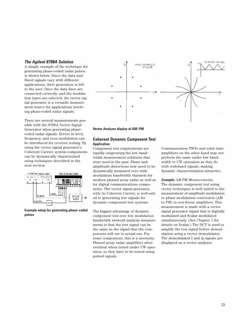
The Agilent 8780A SolutionA simple example of the technique forgenerating phase-coded radar pulsesis shown below. Since the data andBurst signals vary with differentapplications, their generation is leftto the user. Once the data lines areconnected correctly, and the modula-tion types are selected, the vector sig-nal generator is a versatile measure-ment source for applications involv-ing phase-coded radar signals.
There are several measurements pos-sible with the 8780A Vector SignalGenerator when generating phase-coded radar signals. Errors in level,frequency, and even modulation canbe introduced for receiver testing. Byusing the vector signal generator’sCoherent Carrier, system componentscan be dynamically characterizedusing techniques described in thenext section.
Example setup for generating phase-codedpulses
Vector Analyzer display of AM-PM
Coherent Dynamic Component Test Application Component test requirements arerapidly outgrowing the low band-width measurement solutions thatwere used in the past. Phase andamplitude distortions now need to bedynamically measured over widemodulation bandwidth channels formodern phased array radar as well asfor digital communications compo-nents. The vector signal generator,with its Coherent Carrier, is well-suit-ed to generating test signals fordynamic component test systems.
The biggest advantage of dynamiccomponent test over low modulationbandwidth network analysis measure-ments is that the test signal can bethe same as the signal that the com-ponents will see in actual use. Forsome components, this is a necessity.Phased array radar amplifiers oftenoverheat when tested under CW oper-ation, so they have to be tested usingpulsed signals.
Communication TWTs and solid stateamplifiers on the other hand may notperform the same under low band-width or CW operation as they dowith wideband signals, makingdynamic characterization attractive.
Example: AM-PM Measurements.The dynamic component test usingvector techniques is well suited to themeasurement of amplitude modulationto phase modulation conversion (AMto PM) in non-linear amplifiers. Thismeasurement is made with a vectorsignal generator signal that is digitallymodulated and Scalar modulatedsimultaneously. (See Chapter 1 fordetails on Scalar.) The DUT is used toamplify the test signal before demod-ulation using a vector demodulator.The demodulated I and Q signals aredisplayed on a vector analyzer.
24
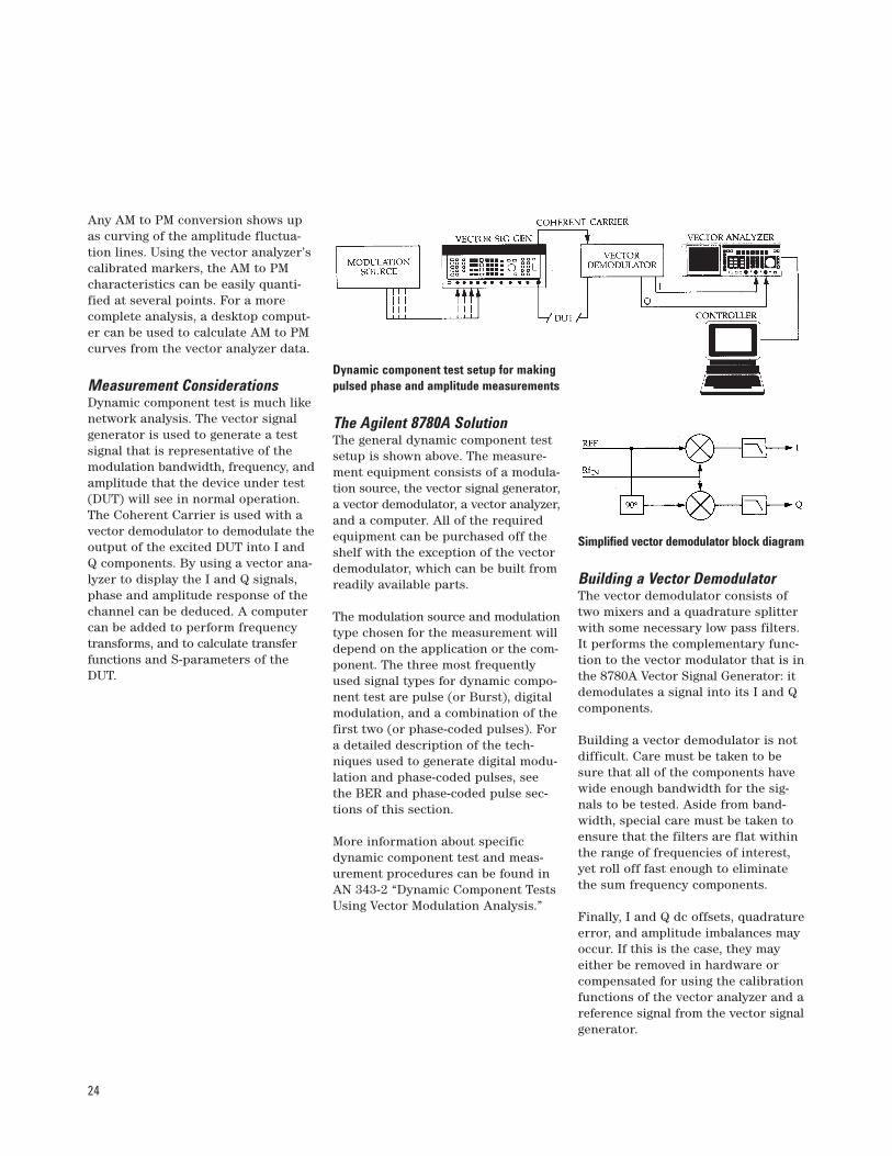
Any AM to PM conversion shows upas curving of the amplitude fluctua-tion lines. Using the vector analyzer’scalibrated markers, the AM to PMcharacteristics can be easily quanti-fied at several points. For a morecomplete analysis, a desktop comput-er can be used to calculate AM to PMcurves from the vector analyzer data.
Measurement ConsiderationsDynamic component test is much likenetwork analysis. The vector signalgenerator is used to generate a testsignal that is representative of themodulation bandwidth, frequency, andamplitude that the device under test(DUT) will see in normal operation.The Coherent Carrier is used with avector demodulator to demodulate theoutput of the excited DUT into I andQ components. By using a vector ana-lyzer to display the I and Q signals,phase and amplitude response of thechannel can be deduced. A computercan be added to perform frequencytransforms, and to calculate transferfunctions and S-parameters of theDUT.
Dynamic component test setup for makingpulsed phase and amplitude measurements
The Agilent 8780A SolutionThe general dynamic component testsetup is shown above. The measure-ment equipment consists of a modula-tion source, the vector signal generator,a vector demodulator, a vector analyzer,and a computer. All of the requiredequipment can be purchased off theshelf with the exception of the vectordemodulator, which can be built fromreadily available parts.
The modulation source and modulationtype chosen for the measurement willdepend on the application or the com-ponent. The three most frequentlyused signal types for dynamic compo-nent test are pulse (or Burst), digitalmodulation, and a combination of thefirst two (or phase-coded pulses). Fora detailed description of the tech-niques used to generate digital modu-lation and phase-coded pulses, seethe BER and phase-coded pulse sec-tions of this section.
More information about specificdynamic component test and meas-urement procedures can be found inAN 343-2 “Dynamic Component TestsUsing Vector Modulation Analysis.”
Simplified vector demodulator block diagram
Building a Vector DemodulatorThe vector demodulator consists oftwo mixers and a quadrature splitterwith some necessary low pass filters.It performs the complementary func-tion to the vector modulator that is inthe 8780A Vector Signal Generator: itdemodulates a signal into its I and Qcomponents.
Building a vector demodulator is notdifficult. Care must be taken to besure that all of the components havewide enough bandwidth for the sig-nals to be tested. Aside from band-width, special care must be taken toensure that the filters are flat withinthe range of frequencies of interest,yet roll off fast enough to eliminatethe sum frequency components.
Finally, I and Q dc offsets, quadratureerror, and amplitude imbalances mayoccur. If this is the case, they mayeither be removed in hardware orcompensated for using the calibrationfunctions of the vector analyzer and areference signal from the vector signalgenerator.
25
FundamentalsThe FM capabilities of the vector signalgenerator serve two purposes in gen-erating test signals. For many applica-tions, the linearity and low distortionspecifications of the FM circuitry makeit the perfect primary modulationsource. Where another modulationtype is primary (like a digital vectormodulation), the vector signal genera-tor’s low phase noise FM capabilitiescan be used to simulate Doppler shiftsor to test carrier recovery loop band-widths.
The Modulation SourceFrequency modulation requires onemodulation source. The specified fullscale range is ±0.5 V for dc coupled FMand 1 Vp-p for ac coupled FM. FM sen-sitivity is selected with the SET FM key,and the value selected corresponds tothe peak-to-peak deviation that will begenerated by full scale inputs. FM sensi-tivity has a range of 50 kHz to 50 MHzfor ac FM and 150 Hz to 150 kHz fordc FM. Allowable rates for ac FM anddc FM are 20 Hz to 12 MHz and dc to10 kHz respectively.
AC coupled FM will normally be themodulation type desired. DC coupledFM was designed primarily for phaselocking the vector signal generator. dc FM has very low modulation band-widths and preserves the vector signalgenerator’s low phase noise charac-teristics. If ac coupled deviations aredesired with dc coupling, there is aspecial dc FM mode that allows up to50 MHz p-p deviations at rates up to10 kHz.
Generating Chirps For RadarReceiver Measurements ApplicationThe vector signal generator’s FM andsimultaneous Burst are suited to gen-erating chirp radar test signals.
There are two components in a chirpmodulation: the amplitude envelopeand the frequency modulation. A chirpcan be generated with an FM sourceand a Burst source. Normally, the FMpart of the pulse is a linear ramp andthe pulse envelope is square. Both ofthese signals have to be synchronized,and if turn-on phase is important, theamplitude and frequency envelopeshould be synchronized to the vectorsignal generator carrier signal.
When generating chirp signals, thegenerator is a versatile measurementsource for radar receiver testing. Level,frequency, and many other parame-ters can be changed to stress thereceiver.
Measurement ConsiderationsThe three most important parametersof a chirp signal are length of the pulse,frequency deviation, and on/off ratio.Using function generators as modula-tion sources allows easy adjustmentof all three parameters. Chirp lengthcan be controlled by varying pulsewidth and sawtooth rate. FM devia-tion is set with the SET FM and levelof the FM input. Pulse depth on thevector signal generator is specified tobe >50 dB (typically 55 dB) and canbe improved with an external pulsemodulator.
Frequency Modulation Operation and Applications

26
The FM ramp may be generated witheither ac coupled or special functionWideband dc FM. AC coupled FM gen-erates a chirp signal centered at thevector signal generator’s tuned fre-quency. With dc FM the chirp signalgenerated will start and stop at thefrequencies determined by the FMinput signal, but in the Wideband dc FMmode dc offsets may affect frequencyaccuracy (typically <1 MHz offset).
Since radar chirps are often very wide-band, it may be necessary to overdrivethe FM input of the vector signal gen-erator to achieve wide enough devia-tions. Although the full-scale FM inputsare specified to be ±0.5 V and 1 Vp-pfor dc and ac coupling, respectively,greater deviations are possible byexceeding these levels. The FM inputis protected by a relay which will pre-vent damaging the FM circuitry, but itwon’t disconnect the input until levelsreach 5 Vp-p or 2.5 V average. Byoverdriving the FM input, peak-to-peak deviations up to 250 MHz aretypically possible using ac coupledFM or special function Wideband dcFM.
The Agilent 8780A SolutionTo generate a chirp pulse with thevector signal generator, two externalmodulation sources are required: an FMand a Burst source. These signals canbe generated with function generatorssuch as the Agilent 8165A and 8116A.With the function generator timebaselocked to the 8780A, the start phase ofsuccessive chirps will be within a cou-ple of degrees of one another.
If greater than 50 dB depth is required,an external modulator such as theAgilent 8730 series can be used toprovide an 80 dB on/off ratio withrise times of 30 nanoseconds.
Example setup for generating wideband chirps with the same starting phase withrespect to the Coherent Carrier

27
Satellite Video Signal Generation Application The ac FM portion of the vector signalgenerator was designed to exceed thestrictest requirements of satellite videosignal generation. Although there aremany different ways to generate satel-lite video signals, the approach outlinedin this section addresses most of theconcerns that one might encounterusing the vector signal generator.
The vector signal generator’s FMmodulator provides good perform-ance for a wide range of modulatingsignals, but performance is optimizedfor deviations of 27.6 MHz p-p, cover-ing the deviation of most satellitevideo signals. At this deviation thevector signal generator’s typical dif-ferential gain and phase are <2% and<1°, respectively. Other characteris-tics which set the FM capabilities ofthe instrument apart are given below:
Frequency Response(50 Hz to 8 MHz): <±0.5 dB
Field Time Distortion: <1%Luminance to Chrominance Delay:<20 ns
Luminance to Chrominance Gain:<±0.3 dB
Measurement ConsiderationsThere are three components to asatellite video signal: the video signal,the audio signal, and the energy dis-persal signal (EDS). To generate asatellite video signal, the sum of thesethree signals is applied to the FMinput of the vector signal generator.
The video signal will usually comefrom a standard video source or adedicated video pattern generator.Before the video portion of the signalcan be added to the other two compo-nents, it must be passed through aCCIR 405-1 video preemphasis filter.
The audio portion of the signal isusually modulated onto a subcarrierbetween 5.5 to 7.5 MHz before beingadded to the FM input. It is also fil-tered first with a 75 µs pre-emphasisfilter.
The EDS portion of the modulatingsignal is derived from the video signaland has no filtering before additionto the modulating signal.
Following the summer used to add thethree components, an amplifier may berequired. The maximum input sensitiv-ity of the 8780A is 50 MHz p-p/1 Vp-p,which means that about a 0.55 Vp-psignal level is needed for 27.6 MHz p-pdeviations.
The Agilent 8780A SolutionA block diagram of the componentsneeded for satellite video signal gen-eration is shown. Since measurementneeds vary, the diagram serves onlyas an example that addresses all ofthe basic requirements of satellitevideo generation. For some applica-tions, the audio or EDS generatorsmay not be required, and the outputof the vector signal generator mayneed additional conditioning (e.g., up-conversion or the addition of noise)before being applied to the deviceunder test.
Complete satellite video signal simulation block diagram

28
For many measurements, the tunableRF output of the vector signal genera-tor will have to be shifted up in fre-quency. The vector signal generatorcovers a 10 MHz to 3 GHz range, butwith a few readily available parts andan up-conversion source, it can pro-duce microwave test signals as well.
Up-Converting The RF OutputThere are three parts of an up-con-version system: an up-conversionsource, a mixer, and a filter. In somecases, the filter will not be neededbecause the device under test willhave its own input filter.
The most important part in the up-conversion process is the up-conver-sion source. The final output frequen-cy will be the sum or difference of thevector signal generator’s frequencyand the up-conversion source’s fre-quency, and any noise inherent in theup-conversion signal (phase noise inparticular) will be transferred ontothe test signal. Since the systems thatthe vector signal generator is used totest are particularly sensitive tophase noise, a very clean sourceshould be chosen for up-conversion.The Agilent 8671B Synthesized CWGenerator is a good choice offeringsynthesizer performance at an eco-nomical price.
The other two parts of the upconver-sion system, the mixer and the filter,should also be carefully selected. Themost important characteristic ofthese components, aside from operat-ing at the correct frequencies, is theirbandwidth. The mixer and the filtershould have bandwidths that exceedthose of the signals to be generatedby the vector signal generator. For themixer, the IF and RF ports shouldhave wide bandwidths, but the LOport doesn’t have to—provided it cov-ers the LO frequency. The filtershould also have a flat responsethrough the passband so it doesn’tdegrade the signal.
To reduce the complexity of the filter,the vector signal generator and LOfrequencies should be chosen to sepa-rate the sum and difference frequen-cies as much as possible.
Up-Converting The Vector Signal Generator
Simple up-conversion of the vector signal generator to microwave frequencies

29
The Coherent Carrier And Up-ConversionThere are some special considerationswhen using the Coherent Carrier withup-converted signals. If these consid-erations are observed, componenttests, demodulator tests, and othersthat require the reference can also bedone at higher microwave frequencies.
After the RF output has been up-con-verted to perform a measurement at amicrowave frequency, it can be down-converted using the same LO that wasused in the up-conversion. When thisis done, the Coherent Carrier can beused normally to demodulate the down-converted test signal.
If demodulation has to be done atmicrowave frequencies, both the RFoutput and the Coherent Carrier willhave to be up-converted. The sametechnique used to up-convert the RFoutput applies to the Coherent Carrier.But, because the Coherent Carrier isa narrow-band signal, the demandson the mixers and filters used to up-convert it are less stringent. The sameLO used to up-convert the RF outputmay also be used to up-convert theCoherent Carrier, simplifying thesetup. Calibrating a vector demodula-tor at higher microwave frequenciesis one example of the need for an up-converted Coherent Carrier.
When using the Coherent Carrier as ademodulator LO signal, the high powerCoherent Carrier option (Option 002)will ensure sufficient power for driv-ing mixers. Option 002 increases theCoherent Carrier output power from–20 dBm to typically >+10 dBm.
Up-conversion of Coherent Carrier with the RF Output
Using the Coherent Carrier with the up-converted RF Output
30
Special functions might be called hid-den features. They represent the effortsof the design team to provide as muchversatility as possible by preservingsome of the most arbitrary controlcapabilities of the instrument. Specialfunctions don’t usually appear on thefront panel of the instrument; this isdone to simplify front panel design andto make the instrument easier to use.As a consequence, though, some of thecapabilities of an instrument like theAgilent 8780A are “hidden.” Pleaseread this section and see if the needsof your application are addressed byone or more of the special functions.
Show Active Specials (0.0)This special function displays on theLCD the other special functions thatare currently selected.
Lock Step, Extend Range (1.0–1.1)This special function locks the stepattenuator and extends the outputlevel range tunable with the vernier.This is important when performingsensitivity measurements near a stepattenuator switch point when thestep attenuator switching might inter-fere with the measurement. Typicalrange extension is about 10 dB lowerand 0.1 dB higher than the unextend-ed range.
At the high and low ends of the exten-sion, some performance degradationis expected, and vector accuracy isunspecified.
Wideband dc FM (2.0–2.1)Wideband dc FM is an unspecifiedfrequency modulation mode thatallows up to ±50 MHz deviations atup to 10 kHz rates. Higher deviationsare possible by over-driving the FMinput with average signal values typi-cally up to ±2.5 V (up to 250 MHz p-pdeviations). The input is protectedwith a relay which disconnects thedriving input if the driving signal’saverage value is too high.
BB Filter Override (3.0–3.1)BB Filter Override is used to selectone of the four built-in spectral limit-ing filters for use with digital modula-tions. Normally the 8780A selects aspectral limiting filter that has apassband less than half the tuned fre-quency to avoid the spectral foldingthat happens when modulation band-widths greater than the generator’sfrequency are combined. BB filteroverride allows either higher or lowerpassband filters to be selected fromthose in the instrument.
The four low pass BB filters availablein the 8780A have the following ap-proximate 3 dB frequencies: 40 MHz,90 MHz, 180 MHz, and 250 MHz. The3 dB roll off frequency for the I and Qchannels without filters is >350 MHz.
External Filter Correction Factors (4.0–5.1) Although the vector signal generatorcan calibrate through external dc cou-pled filters, you may want to enteryour own correction factors for accoupled or dc coupled filters. Thisspecial function allows you to do that.You can select losses in the range of 0to 3 dB with a resolution of 0.1 dB.Filters with loss or gain out of thisrange are not recommended for usewith the 8780A.
Appendix A. Special Functions

31
Carrier Leakage (6.0–6.1) Permits the addition of some amountof carrier to a digitally modulated sig-nal; it lets you “spike” a signal. Carrierleakage is selected in dBc and can befrom -40 to -3 dBc. Carrier leakage isalways added in the I channel. Digitalmodulation accuracy may be adverselyaffected, especially for large amountsof carrier leakage.
Internal PRBS Generation (7.0–7.1) The vector signal generator can use itsown microprocessor to generate pseu-do random bit sequences to drive itsdigital input lines. Although too slowfor BER testing (typically 5 kHz), theinternal PRBS signals simplify gener-ation of test patterns. Since all of thedigital lines are driven by differenttaps of the same 215 -1 sequence, anyvector signal generator digital modu-lation can be generated.
Fast Frequency Switching (8.0–8.1) This function decreases the typicaltime required to switch the outputfrequency of the vector signal genera-tor to 100 ms. The reduced switchingtime is achieved by not readjusting theoutput level each time a new frequencyis selected. For automated tests wheremany measurements have to be madequickly over a narrow band, this specialfunction can cut total measurementtime in half.
All Modulation Off (11.0) Provides a convenient way to turn offall modulations presently active. It isespecially useful when several modu-lations are being used simultaneously.
Blank Display (12.0–12.1)Used to turn the vector signal genera-tor’s LCD display off to prevent possi-bly sensitive information from beingshown. This is especially valuable forsecure system measurements wherefrequencies and modulations must bekept secret.
Phase Bump (13.0–13.1)Shifts the RF output phase with respectto another synthesizer’s output, pro-vided that the two synthesizers arephase locked. Phase Bump can intro-duce phase shifts up to ±360 degreesin 0.1 degree increments. Phase Bumpdoes not shift the phase between thevector signal generator’s RF outputand Coherent Carrier. Since the phaseof any synthesizer may drift slightlywith respect to its reference, PhaseBump stability is not specified.
DAC Control (14.0–15.2) This function lets you directly set anyof the vector signal generator’s thirteeninternal digital-to-analog convertersfrom the front panel. You can controlthe digital states within the I/Q plane,the quadrature of the modulator, andI and Q channel attenuation.
Selective Calibrations (20.0–20.3)These functions calibrate only thebaseband, output, or FM sections ofthe instrument instead of the completecalibration that is done by the frontpanel CAL key. This may be importantin automated test systems where manymeasurements have to be made quicklyand calibration time can be costly. Byperforming only the calibration perti-nent to the measurement being made,you can save time and ensure accurateoperation of the vector signal generator.
Set GPIB Address (25.0)The 8780A GPIB address is set orchanged using this special functionfrom the front panel.
Service Voltmeter (52.0–52.8)Acts like a service probe that canmeasure critical signal voltages in theinstrument to isolate failures or other-wise assure correct operation. One ofeight test points is selected, then thevoltage at that point is displayed onthe vector signal generator front panel.
Direct Control (53.0–53.3) Used to program any of the 8780A’sinternal control latches. These latchescontrol all DAC, attenuator, filter, andother hardware settings. In fact, mostother specials represent a simplifiedway of doing what could have beendone using Direct Control.
Hard Reset (99.9) Used to set the vector signal generatorto its original configuration. It erasesall user-set frequencies, instrumentconfigurations, and recent calibrationinformation.

32
PR Presets the instrumentSP0 Turns off all special functionsSY, ST Stores current instrument settingSSP Sets special functionRC Recalls an instrument settingCL Calibrates instrumentEC0 Selects asynchronous operationEC1 Selects one clock operationEC2 Selects two clock operationCK0 Sets clock level to ‘auto’CK1 Sets clock level to ‘ECL’CK2 Sets clock level to ‘GND’DL0 Sets data level to ‘VAR’DL1 Sets data level to ‘ECL’DL2 Sets data level to ‘GND’EF0 Unselects external filtersEF1 Selects external filtersDF0 Selects AC FM couplingDF1 Selects DC FM couplingIFM Inverts or uninverts FM inputIPI Inverts a digital inputIPN Sets input to not invertedUP Adds the increment to current set
valueDN Subtracts the increment from cur-
rent set valueFR Sets frequencyCF Enters set frequency stateLV, LE, Enters set level stateAP,PLIO Sets the I1 stateIT Sets the I2 stateQO Sets the Ql stateQT Sets the Q2 state
RO Sets the R1 stateRT Sets the R2 stateAO Sets the phi1 stateAT Sets the phi2 stateSFM Sets FM deviationSAL Sets alternate levelSIQ Sets I<QAI Sets alternate level IVA Sets variable data levelIS Sets increment valueGZ GHz terminatorMZ MHz terminatorKZ kHz terminatorHZ Hz terminatorDBM dBm terminatorVL Volts terminatorMV Millivolts terminatorUV mvolts terminatorDBR dB terminatorPC Percent terminatorEN Enter terminatorKN0 Disables the knobKN1 Enables the knobCW Turns off all modulationsFM0 Turns off FMFM1 Turns on FMBP0 Turns off BPSKBP1 Turns on BPSKEP0 Turns off 8PSKEP1 Turns on 8PSKTS0 Turns off two-stateTS1 Turns on two-stateVM0 Turns off vector modulationVM1 Turns on vector modulation
QP0 Turns off QPSKQP1 Turns on QPSKQA0 Turns off 16QAMQA1 Turns on 16QAMSTQ0 Turns off 64QAMSTQ1 Turns on 64QAMAL0 Turns off alternate levelAL1 Turns on alternate levelBR0 Turns off BurstBR1 Turns on BurstSC0 Turns off ScalarSC1 Turns on ScalarIQ0 Turns I<Q offIQ1 Turns I<Q onRF0 Disables RF outputRF1 Enables RF outputCR Moves cursor in set modesRM Enables service request mask
responseCS Sets status byte to zeroLP1 Enables system configuration
responseLP2 Enables system status responseDE Turns LCD display onDD Turns LCD display offDA Turns on all LCD display seg-
ments@1 Accepts next character as ‘binary
request service mask’?ID Enables GPIB address response?CL Enables "still calibrating?"
responseSM Enables system status message
response
Appendix B. GPIB Commands
Service Request Mask:
8 7 6 5 4 3 2 1
not RQS soft ready power hard not calused error fail error used done
Agilent Technologies’ Test and MeasurementSupport, Services, and AssistanceAgilent Technologies aims to maximize the value you receive, while minimizingyour risk and problems. We strive toensure that you get the test and measure-ment capabilities you paid for and obtainthe support you need. Our extensive sup-port resources and services can help youchoose the right Agilent products for yourapplications and apply them successfully.Every instrument and system we sell has a global warranty. Support is available for at least five years beyond the produc-tion life of the product. Two conceptsunderlie Agilent’s overall support policy:“Our Promise” and “Your Advantage.”
Our Promise“Our Promise” means your Agilent testand measurement equipment will meet itsadvertised performance and functionality.When you are choosing new equipment,we will help you with product informa-tion, including realistic performance spec-ifications and practical recommendationsfrom experienced test engineers. When
you use Agilent equipment, we can verifythat it works properly, help with productoperation, and provide basic measurementassistance for the use of specified capabil-ities, at no extra cost upon request. Manyself-help tools are available.
Your Advantage“Your Advantage” means that Agilentoffers a wide range of additional experttest and measurement services, which youcan purchase according to your uniquetechnical and business needs. Solve prob-lems efficiently and gain a competitive edgeby contracting with us for calibration, extra-cost upgrades, out-of-warranty repairs, andon-site education and training, as well as design, system integration, project man-agement, and other professional services.Experienced Agilent engineers and techni-cians worldwide can help you maximizeyour productivity, optimize the return oninvestment of your Agilent instruments andsystems, and obtain dependable measure-ment accuracy for the life of those products.
By internet, phone, or fax, get assistancewith all your test and measurement needs.
Online Assistancewww.agilent.com/find/assistPhone or FaxUnited States:(tel) 1 800 452 4844
Canada:(tel) 1 877 894 4414(fax) (905) 282-6495
Europe:(tel) (31 20) 547 2323(fax) (31 20) 547 2390
Japan:(tel) (81) 426 56 7832(fax) (81) 426 56 7840
Latin America:(tel) (305) 269 7500(fax) (305) 269 7599
Australia:(tel) 1 800 629 485 (fax) (61 3) 9210 5947
New Zealand:(tel) 0 800 738 378 (fax) (64 4) 495 8950
Asia Pacific:(tel) (852) 3197 7777(fax) (852) 2506 9284
Product specifications and descriptions in this document subject to change without notice.
Copyright © 1986, 2000 Agilent TechnologiesPrinted in U.S.A. 10/005954-6368