Agilent MIPI D-PHY Protocol Test Solutions N4851A/B MIPI · PDF fileN4851A/B and N4861A/B MIPI...
16
Agilent MIPI D-PHY Protocol Test Solutions N4851A/B MIPI D-PHY Acquisition Probe N4861A/B MIPI D-PHY Stimulus Probe Data Sheet Applications • MIPI D-PHY hardware prototype turn-on and debug • System integration of embedded controller with MIPI D-PHY display and camera devices • Troubleshooting interoperability issues • Robustness test with error injection • Software debug of MIPI D-PHY-based systems Key features • Combined MIPI D-PHY real-time analysis and stimulus test solution • Real-time trace of MIPI D-PHY bus modes • Decoding and visualization of CSI-2 and DSI protocols • Easy trigger setup with predefined pattern library • Hierarchical trace display capabilities • Accelerate your MIPI D-PHY test development • Simplify your MIPI D-PHY test environment by combining stimulus and analysis • Automatic stimulus generation from bitmap picture • Full custom traffic generation • Capture and replay capabilities • Link layer test with parametric control of voltages and timing • Based on a modular, scalable, logic analyzer platform for multi-bus, system-level measurements • Multilevel trigger sequencer to trigger the analyzer on complex event conditions
-
Upload
truonglien -
Category
Documents
-
view
265 -
download
2
Transcript of Agilent MIPI D-PHY Protocol Test Solutions N4851A/B MIPI · PDF fileN4851A/B and N4861A/B MIPI...
Agilent
MIPI D-PHY Protocol Test Solutions
N4851A/B MIPI D-PHY Acquisition Probe
N4861A/B MIPI D-PHY Stimulus Probe
Data Sheet
Applications
• MIPI D-PHY hardware prototype
turn-on and debug
• System integration of embedded
controller with MIPI D-PHY display
and camera devices
• Troubleshooting interoperability
issues
• Robustness test with error injection
• Software debug of
MIPI D-PHY-based systems
Key features
• Combined MIPI D-PHY real-time
analysis and stimulus test solution
• Real-time trace of MIPI D-PHY bus
modes
• Decoding and visualization of CSI-2
and DSI protocols
• Easy trigger setup with predefined
pattern library
• Hierarchical trace display
capabilities
• Accelerate your MIPI D-PHY test development
• Simplify your MIPI D-PHY test environment by combining stimulus and analysis
• Automatic stimulus generation from
bitmap picture
• Full custom traffic generation
• Capture and replay capabilities
• Link layer test with parametric
control of voltages and timing
• Based on a modular, scalable, logic
analyzer platform for multi-bus,
system-level measurements
• Multilevel trigger sequencer to
trigger the analyzer on complex
event conditions

www.agilent.com/fi nd/MIPI 2
N4851A/B and N4861A/B MIPI D-PHY Analysis and Stimulus Test
MIPI D-PHY is a packet-based
interconnect standard defined for
use in wireless mobile devices as the
communication bus between the main
components such as the embedded
controller (BB-IC) and cameras and
displays.
When you adopt the MIPI D-PHY
standard in your designs, you will face
new test challenges during the debug,
integration and system validation
phases of the development process.
To ensure your design operates accord-
ing to the MIPI D-PHY link and CSI-2
or DSI protocol specification, you need
real-time insight on the DUT’s behavior
at various protocol levels, and you
need to be able to trigger on protocol-
specific patterns or error conditions.
To reproduce system problems or run
non-regression tests, you often need
to create traffic conditions that may be
difficult to reproduce with real devices.
The MIPI D-PHY stimulus solution can
accelerate your design/debug/test
cycle by reproducing these conditions.
The specific nature and operation
modes of the MIPI D-PHY serial inter-
connect makes it extremely difficult to
analyze or to stimulate with general-
purpose test instruments.
Now you can get the capabilities
you need with the N4851A/B and
N4861A/B analysis and stimulus
solution.
The Agilent Technologies N4851A/B
acquisition probe and the N4861A/B
stimulus probe operate in conjunction
with Agilent 16800 and 16900 Series
logic analyzers to provide the digital
serial stimulus and acquisition capabil-
ities required to independently debug
and test a MIPI D-PHY component,
or integrate your MIPI D-PHY-based
mobile designs.
Thanks to the modular and scalable
architecture of Agilent 16800 and
16900 logic analyzers, the MIPI D-PHY
analysis and stimulus measurements
can be time-correlated with other mea-
surements (control logic, other serial
buses, memory) on the device under
test, helping you perform system-level
measurements.
Cross triggering capabilities help you
observe the activity on a bus when
a specific event happens on another
bus, helping you find the root cause of
complex system-level problems.
With this versatile architecture, you
can use the same platform from the
bus design phase to system-level test,
so you reduce your expenditure on test
equipment.
This common, scalable system for
protocol analysis and traffic generation
protects your financial investment for
years to come.
Combine custom traffic generation and real-time analysis to diagnose and
characterize your system faster

www.agilent.com/fi nd/MIPI3
Typical Configurations
MIPI D-PHY analysis configuration
• In analysis-only mode, the
N4851A/B transparently captures
traffic between two devices.
• Link activity and protocol
operation (CSI, DSI) is captured
through various probing solutions,
from flying leads to soft-touch
connectors.
• The analyzer includes a multilevel
sequencer to trigger the analyzer on
complex event conditions.
• Multiple analyzers can be
synchronized and cross triggered for
system-level measurements.
N4851A/B MIPI D-PHY acquisition probe
N4861A/B MIPI D-PHY stimulus probe
Soft touch connectorless probes reduce
cost and shorten your design cycle by
eliminating probing connectors
Flying leads signal probing solution
MIPI D-PHY stimulus and analysis solution
• In active test mode (stimulus +
analysis), a customizable stimulus is
sent to the DUT, with simultaneous
analysis of the response.
• The stimulus solution can be used
to test peripherals, such as display
devices, by simulating a system
controller.
• Stimulus patterns can be defined in
multiple ways:
◦ File-based stimulus
◦ GUI-based stimulus
◦ Record and play pattern
◦ Bitmap-based Stimulus
www.agilent.com/fi nd/MIPI 4
N4851A/B Protocol Analysis Gives You Fast Insight into Your System
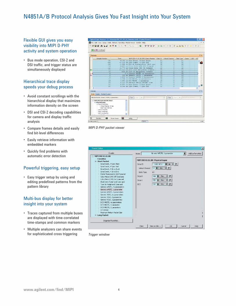
Flexible GUI gives you easy visibility into MIPI D-PHY activity and system operation
• Bus mode operation, CSI-2 and
DSI traffic, and trigger status are
simultaneously displayed
Hierarchical trace display speeds your debug process
• Avoid constant scrollings with the
hierarchical display that maximizes
information density on the screen
• DSI and CSI-2 decoding capabilities
for camera and display traffic
analysis
• Compare frames details and easily
find bit-level differences
• Easily retrieve information with
embedded markers
• Quickly find problems with
automatic error detection
Powerful triggering, easy setup
• Easy trigger setup by using and
editing predefined patterns from the
pattern library
Multi-bus display for better insight into your system
• Traces captured from multiple buses
are displayed with time-correlated
time-stamps and common markers
• Multiple analyzers can share events
for sophisticated cross triggering
MIPI D-PHY packet viewer
Trigger window

www.agilent.com/fi nd/MIPI5
Image Inserter and Image Extractor Applications
Quickly build MIPI DSI stimulus from bitmap files with the Image Inserter application
• Save hours of development and
editing
• Configurable formats, bitmap
encoding
• Multiframe generation
• Virtual channel support
• Supports burst mode, non-burst
mode, command mode
• Supports initialization commands
Visualize bitmaps from real time trace files with the Image Extractor application
• Reconstruct picture from DSI trace
• Virtual channel support
• Multiple frame support
DSI Image Inserter
DSI Image Extractor
www.agilent.com/fi nd/MIPI 6
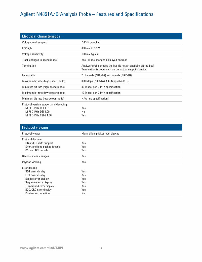
Agilent N4851A/B Analysis Probe – Features and Specifications
Electrical characteristics
Voltage level support D-PHY compliant
LPVhigh 800 mV to 3.3 V
Voltage sensitivity 100 mV typical
Track changes in speed mode Yes - Mode changes displayed on trace
Termination Analyzer probe snoops the bus (is not an endpoint on the bus)
Termination is dependent on the actual endpoint device
Lane width 2 channels (N4851A), 4 channels (N4851B)
Maximum bit rate (high-speed mode) 800 Mbps (N4851A), 940 Mbps (N4851B)
Minimum bit rate (high-speed mode) 80 Mbps, per D-PHY specification
Maximum bit rate (low-power mode) 10 Mbps, per D-PHY specification
Minimum bit rate (low-power mode) N/A ( no specification )
Protocol version support and decoding
MIPI D-PHY DSI 1.01
MIPI D-PHY DSI 1.00
MIPI D-PHY CSI-2 1.00
Yes
No
Yes
Protocol viewing
Protocol viewer Hierarchical packet-level display
Protocol decoder
HS and LP data support
Short and long packet decode
CSI and DSI decode
Yes
Yes
Yes
Decode speed changes Yes
Payload viewing Yes
Error decode
SOT error display
EOT error display
Escape error display
Sequence error display
Turnaround error display
ECC, CRC error display
Contention detection
Yes
Yes
Yes
Yes
Yes
Yes
No

www.agilent.com/fi nd/MIPI7
Agilent N4851A/B Analysis Probe – Features and Specifications (continued)
Triggering capabilities
Trigger on protocol patterns Yes, on both DSI and CSI long and short patterns
Protocol pattern customization Yes, with bit-level editing
Real-time error detection
SOT error trigger
EOT error trigger
Escape error trigger
Sequence error trigger
Turnaround error trigger
Yes, on a per lane basis
Yes, on a per lane basis
Yes, on a per lane basis
Yes, on a per lane basis
Yes, on a per lane basis
Display
Low power state of data transmission Yes
Ultra-low power state Not visible in the trace
Stopped Yes
www.agilent.com/fi nd/MIPI 8
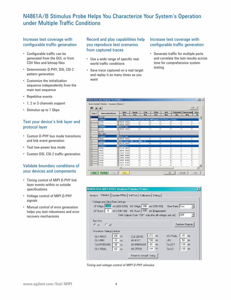
N4861A/B Stimulus Probe Helps You Characterize Your System’s Operation under Multiple Traffic Conditions
Increase test coverage with configurable traffic generation
• Configurable traffic can be
generated from the GUI, or from
CSV files and bitmap files
• Deterministic D-PHY, DSI, CSI-2
pattern generation
• Customize the initialization
sequence independently from the
main test sequence
• Repetitive events
• 1, 2 or 3 channels support
• Stimulus up to 1 Gbps
Test your device’s link layer and protocol layer
• Custom D-PHY bus mode transitions
and link event generation
• Test low-power bus mode
• Custom DSI, CSI-2 traffic generation
Validate boundary conditions of your devices and components
• Timing control of MIPI D-PHY link
layer events within or outside
specifications
• Voltage control of MIPI D-PHY
signals
• Manual control of error generation
helps you test robustness and error
recovery mechanisms
Record and play capabilities help you reproduce test scenarios from captured traces
• Use a wide range of specific real-
world traffic conditions
• Save trace captured on a real target
and replay it as many times as you
want
Increase test coverage with configurable traffic generation
• Generate traffic for multiple ports
and correlate the test results across
time for comprehensive system
testing
Timing and voltage control of MIPI D-PHY stimulus
www.agilent.com/fi nd/MIPI9
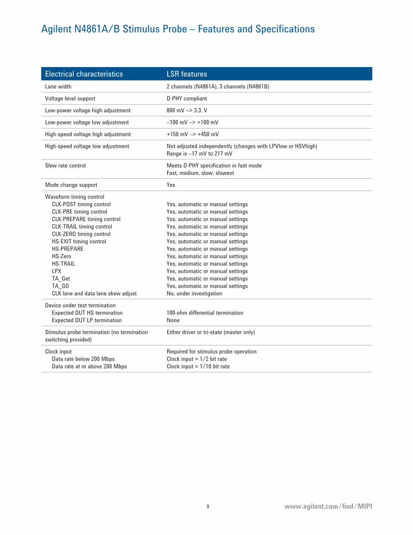
Agilent N4861A/B Stimulus Probe – Features and Specifications
Electrical characteristics LSR features
Lane width 2 channels (N4861A), 3 channels (N4861B)
Voltage level support D-PHY compliant
Low-power voltage high adjustment 800 mV –> 3.3. V
Low-power voltage low adjustment –100 mV –> +100 mV
High-speed voltage high adjustment +150 mV –> +450 mV
High-speed voltage low adjustment Not adjusted independently (changes with LPVlow or HSVhigh)
Range is –17 mV to 217 mV
Slew rate control Meets D-PHY specification in fast mode
Fast, medium, slow, slowest
Mode change support Yes
Waveform timing control
CLK-POST timing control
CLK-PRE timing control
CLK-PREPARE timing control
CLK-TRAIL timing control
CLK-ZERO timing control
HS-EXIT timing control
HS-PREPARE
HS-Zero
HS-TRAIL
LPX
TA_Get
TA_GO
CLK lane and data lane skew adjust
Yes, automatic or manual settings
Yes, automatic or manual settings
Yes, automatic or manual settings
Yes, automatic or manual settings
Yes, automatic or manual settings
Yes, automatic or manual settings
Yes, automatic or manual settings
Yes, automatic or manual settings
Yes, automatic or manual settings
Yes, automatic or manual settings
Yes, automatic or manual settings
Yes, automatic or manual settings
No, under investigation
Device under test termination
Expected DUT HS termination
Expected DUT LP termination
100-ohm differential termination
None
Stimulus probe termination (no termination
switching provided)
Either driver or tri-state (master only)
Clock input
Data rate below 200 Mbps
Data rate at or above 200 Mbps
Required for stimulus probe operation
Clock input = 1/2 bit rate
Clock input = 1/10 bit rate
www.agilent.com/fi nd/MIPI 10
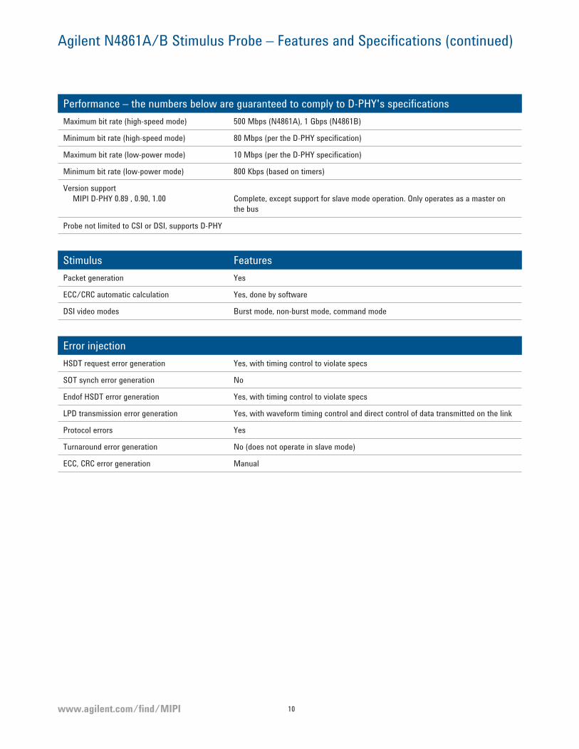
Agilent N4861A/B Stimulus Probe – Features and Specifications (continued)
Performance – the numbers below are guaranteed to comply to D-PHY's specifications
Maximum bit rate (high-speed mode) 500 Mbps (N4861A), 1 Gbps (N4861B)
Minimum bit rate (high-speed mode) 80 Mbps (per the D-PHY specification)
Maximum bit rate (low-power mode) 10 Mbps (per the D-PHY specification)
Minimum bit rate (low-power mode) 800 Kbps (based on timers)
Version support
MIPI D-PHY 0.89 , 0.90, 1.00 Complete, except support for slave mode operation. Only operates as a master on
the bus
Probe not limited to CSI or DSI, supports D-PHY
Stimulus Features
Packet generation Yes
ECC/CRC automatic calculation Yes, done by software
DSI video modes Burst mode, non-burst mode, command mode
Error injection
HSDT request error generation Yes, with timing control to violate specs
SOT synch error generation No
Endof HSDT error generation Yes, with timing control to violate specs
LPD transmission error generation Yes, with waveform timing control and direct control of data transmitted on the link
Protocol errors Yes
Turnaround error generation No (does not operate in slave mode)
ECC, CRC error generation Manual
www.agilent.com/fi nd/MIPI11
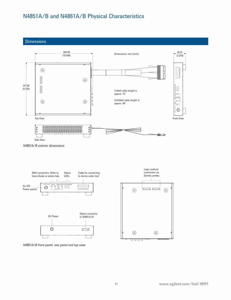
N4851A/B and N4861A/B Physical Characteristics
Dimensions
Se
e U
sers
Gu
ide
or
on
line
he
lpfo
r c
ha
nn
el/
sig
na
l ass
ign
me
nts
31
2M
bp
s D
IGIT
AL
AC
QU
ISIT
ION
PR
OB
EN
48
50
A
DA
TA
CLO
CK
CT
SS
1S
0T
XR
XC
LK
3.3
V M
ax
Ag
ilen
t Te
ch
no
log
ies
Folded cable length is
approx. 15”
Unfolded cable length is
approx. 48”
247.65
(9.750)
269.48
(10.609)56.91
(2.240)
Top View
Side View
Front View
Dimensions: mm/(inch)
N4851A/B exterior dimensions
See Users Guide or online helpfor channel/signal assignments
312Mbps DIGITAL ACQUISITION PROBEN4850A
DATACLOCK
CTSS1 S0TX RX CLK
3.3V Max
Agilent Technologies
On/Off
Power switch
SMA connectors. Refer to
Users Guide or online help
Status
LEDsCable for connecting
to device under test
Logic analyzer
connection via
Samtec probes
DC PowerOption connector
to N4861A/B
N4851A/B front panel, rear panel and top view
www.agilent.com/fi nd/MIPI 12
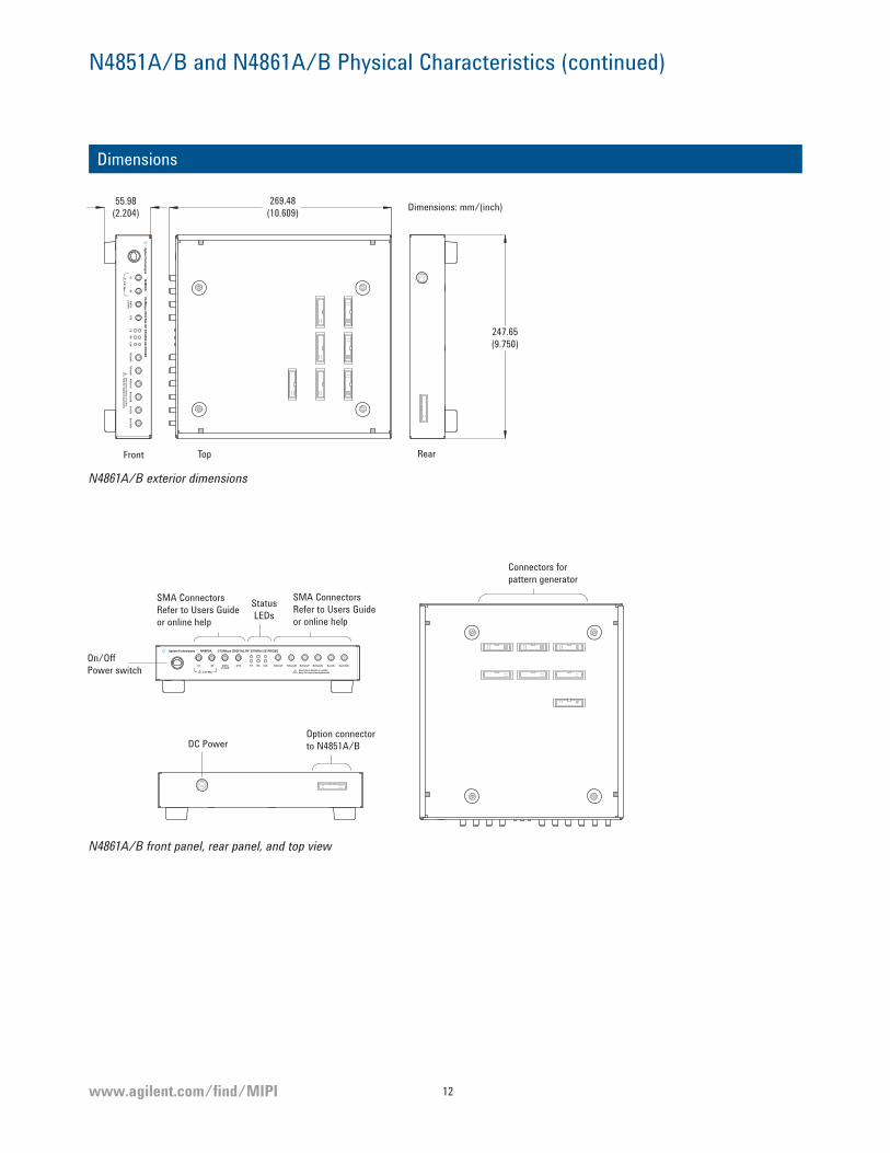
N4851A/B and N4861A/B Physical Characteristics (continued)
Dimensions
Front Top Rear
Se
e U
sers G
uid
e o
r on
line
he
lp fo
r sign
al a
ssign
me
nts
31
2M
bp
s DIG
ITA
L RF
ST
IMU
LUS
PR
OB
EN
48
60
A
DA
TA
CLO
CK
CT
SS
1S
0T
XR
XC
LKR
xD
ata
PR
xD
ata
NTx
Da
taP
TxD
ata
NS
ysClkE
nS
ysClk
3.3
V M
ax
55.98
(2.204)
269.48
(10.609)
247.65
(9.750)
Dimensions: mm/(inch)
N4861A/B exterior dimensions
See Users Guide or onlinehelp for signal assignments
312Mbps DIGITAL RF STIMULUS PROBEN4860A
DATACLOCK
CTSS1 S0 TX RX CLK RxDataP RxDataNTxDataP TxDataN SysClkEnSysClk
3.3V Max
SMA Connectors
Refer to Users Guide
or online help
Status
LEDs
SMA Connectors
Refer to Users Guide
or online help
On/Off
Power switch
Connectors for
pattern generator
DC PowerOption connector
to N4851A/B
N4861A/B front panel, rear panel, and top view
www.agilent.com/fi nd/MIPI13
Ordering Information
When you configure your MIPI D-PHY
measurement system, consider the
following:
Ability to provide MIPI D-PHY stimulus
• For comprehensive stimulus and
response testing of your MIPI
D-PHY device or system, select a
logic analyzer with digital pattern
generation capability (16822A,
16823A, or a 16900 modular logic
analysis system with a 16720A
pattern generator module).
Flexibility to grow as your measurement needs evolve:
• A modular 16900 Series logic
analyzer addresses your
measurement needs today and
allows you to grow as your needs
evolve.
Modification of the logic analyzer’s MIPI D-PHY protocol decoder
• The MIPI D-PHY standard provides
the flexibility to customize your
control structure and data packets
for your specific application. With
the B4641A protocol development
kit, you can modify the logic
analyzer’s MIPI D-PHY protocol
decoder to track your custom
solution.
DUT requirements for use with N4861A/B stimulus probe:
• SMA (m-m) connectors on the
target. The number of SMA
connectors depends on your test
scenario: turn on, validation, or
system integration.
N4851U upgrade kit
If you own an N4851A MIPI D-PHY
analysis probe or an N4861A MIPI
D-PHY stimulus probe, the N4851U
upgrade kit will extend the capabilities
of your test system:
• With the N4851U-004, your N4851A
analysis probe can support up to 4
lanes.
• With the N4851U-004, your N4861A
simtulus probe will support up to 3
lanes.
• One N4851U-004 is required for
each logic analyzer connected to
MIPI D-PHY analysis and stimulus
probes.

www.agilent.com/fi nd/MIPI 14
Ordering Information: Analysis and Stimulus Solution
To configure a complete MIPI D-PHY digital acquisition and stimulus system, you
will need to order or have the following items:
N4861A/B probe, SMA cables
required for target connection
1
Samtec probes5
N4851A/B probe1
Differential flying lead probe4
Logic analyzer3
Pattern generator cables
MIPI D-PHY digital acquisition and stimulus system
Probes between the N4851A/B and the…
1. MIPI D-PHY probes 2. Method to create
data
3. Logic analyzer with
48-channel pattern
generator2
4. Device under test
(One of the
following for each
N4851A/B)
5. Logic analyzer
(Two Samtec
probes per
N4851A/B – one
for Tx and one for
Rx. Select probe
that is compatible
with your logic
analyzer.)
N4861A or N4861B1
digital stimulus probe
• N4861A-040: Two sets
of four 40-inch SMA
cables
N4851A digital
acquisition probe
• -010 for node-locked
license
• -020 for floating
(server) license
N4851B digital
acquisition probe
• Convert captured
logic analyzer trace
to stimulus
• Custom
programmatic
generation
16800 Series portables
• 16822A – 68 ch
• 16823A – 102 ch
16900 Series modular
mainframe with at
least one each of the
following:
• 16900 Series
module(s)
• 16720A pattern
generator module
• E5381A differential
flying lead probe
• E5405A differential
pro series soft touch
probe
• E5387A differential
soft touch probe
• E5385A for logic
analyzers with
a 40-pin cable
connection (16822A,
16823A, 16910/11A)
• E5378A for logic
analyzers with
a 90-pin cable
connection (1695X
modules)
1. N4861A/B digital stimulus probe requires an N4851A/B digital acquisition probe to operate and a clock generator, such as the Agilent 33250A.
2. Compatible with 16800 or 16900 Series logic analyzers with 68 channels or more.

www.agilent.com/fi nd/MIPI15
Ordering Information: Analysis Solution
To configure a complete MIPI D-PHY digital acquisition system, you will need to
order or have the following items:
Samtec probes4
N4851A/B probe1
Differential flying lead probe4
Logic analyzer3
MIPI D-PHY digital acquisition system
Probes between the N4851A/B and the…
1. MIPI probes
(One per Tx/Rx pair)
2. Logic analyzer1 3. Device under test
(One of the following for
each N4851A/B)
4. Logic analyzer
(Two Samtec probes per
N4851A/B – one for Tx
and one for Rx. Select
probe that is compatible
with your logic analyzer)
N4851A digital acquisition probe
• -010 for node-locked license
• -020 for floating (server)
license
N4851B digital acquisition probe
16800 Series portables
• 16802A – 68 ch
• 16803A – 102 ch
• 16804A – 136 ch
• 16806A – 204 ch
• 16822A – 68 ch
• 16823A – 102 ch
16900 Series modular mainframe
with at least one 16900 Series
module
• E5381A differential flying
lead probe
• E5405A differential pro
series soft touch probe
• E5387A differential soft
touch probe
• E5385A Samtec probe for
logic analyzers with a 40-
pin cable connection (16800
Series, 16910/11A)
• E5378A Samtec probe for
logic analyzers with a 90-
pin cable connection (1695X
modules)
1. Compatible with 16800 or 16900 Series logic analyzers with 68 channels or more
www.agilent.com/find/MIPI
Related Agilent literature
Publication title Pub number
Agilent 16800 Series Portable Logic Analyzers Data Sheet 5989-5063EN
Agilent 16900 Series Logic Analysis Mainframes Data Sheet 5989-0421EN
Probing Solutions for Agilent Technologies Logic Analyzers
Catalog
5968-4632E
Product Web site
For the most up-to-date and
complete application and product
information, please visit our
product Web site at:
www.agilent.com/find/MIPI
Remove all doubt
Our repair and calibration services
will get your equipment back to
you, performing like new, when
promised. You will get full value out
of your Agilent equipment through-
out its lifetime. Your equipment
will be serviced by Agilent-trained
technicians using the latest factory
calibration procedures, automated
repair diagnostics and genuine parts.
You will always have the utmost
confidence in your measurements.
For information regarding self
maintenance of this product, please
contact your Agilent office.
Agilent offers a wide range of additional
expert test and measurement services
for your equipment, including initial
start-up assistance, onsite education
and training, as well as design, system
integration, and project management.
For more information on repair and
calibration services, go to:
www.agilent.com/find/removealldoubt
Agilent Email Updates
www.agilent.com/find/emailupdates
Get the latest information on the
products and applications you select.
Agilent Direct
www.agilent.com/find/agilentdirect
Quickly choose and use your test
equipment solutions with confidence.
www.lxistandard.org
LXI is the LAN-based successor to
GPIB, providing faster, more efficient
connectivity. Agilent is a founding
member of the LXI consortium.
For more information on Agilent Technologies’ products, applications or services, please contact your local Agilent office. The complete
list is available at:
www.agilent.com/find/contactus
AmericasCanada (877) 894-4414 Latin America 305 269 7500United States (800) 829-4444
Asia PacificAustralia 1 800 629 485China 800 810 0189Hong Kong 800 938 693India 1 800 112 929Japan 0120 (421) 345Korea 080 769 0800Malaysia 1 800 888 848Singapore 1 800 375 8100Taiwan 0800 047 866Thailand 1 800 226 008
Europe & Middle EastAustria 01 36027 71571Belgium 32 (0) 2 404 93 40 Denmark 45 70 13 15 15Finland 358 (0) 10 855 2100France 0825 010 700* *0.125 €/minute
Germany 07031 464 6333 Ireland 1890 924 204Israel 972-3-9288-504/544Italy 39 02 92 60 8484Netherlands 31 (0) 20 547 2111Spain 34 (91) 631 3300Sweden 0200-88 22 55Switzerland 0800 80 53 53United Kingdom 44 (0) 118 9276201Other European Countries: www.agilent.com/find/contactusRevised: July 2, 2009
Product specifications and descriptions in this document subject to change without notice.
© Agilent Technologies, Inc. 2008, 2009Printed in USA, October 2, 20095989-7921EN
www.agilent.comwww.agilent.com/find/MIPI