Agilent EXA Signal Analyzer N9010A · PDF file1 dB gain compression (two tone) ......
21
LXI class C certified Agilent EXA Signal Analyzer N9010A Data Sheet Available frequency range N9010A-503 9 kHz to 3.6 GHz N9010A-507 9 kHz to 7.0 GHz N9010A-513 9 kHz to 13.6 GHz N9010A-526 9 kHz to 26.5 GHz
Transcript of Agilent EXA Signal Analyzer N9010A · PDF file1 dB gain compression (two tone) ......
LXI class C certified
Agilent EXA Signal Analyzer
N9010A
Data SheetAvailable frequency range
N9010A-503 9 kHz to 3.6 GHz
N9010A-507 9 kHz to 7.0 GHz
N9010A-513 9 kHz to 13.6 GHz
N9010A-526 9 kHz to 26.5 GHz

2
Table of ContentsDefinitions and Conditions . . . . . . . . .3Frequency and Time Specifications . .4 Frequency range . . . . . . . . . . . . . . . . . . . 4 Band . . . . . . . . . . . . . . . . . . . . . . . . . . . . 4 Frequency reference . . . . . . . . . . . . . . . . 4 Frequency readout accuracy . . . . . . . . . 4 Marker frequency counter . . . . . . . . . . . 4 Frequency span . . . . . . . . . . . . . . . . . . . . 5 Sweep time and triggering . . . . . . . . . . . 5 Time gating . . . . . . . . . . . . . . . . . . . . . . . 5 Sweep (trace) point range . . . . . . . . . . . 5 Resolution bandwidth (RBW) . . . . . . . . 5 Analysis bandwidth . . . . . . . . . . . . . . . . 6 Video bandwidth (VBW) . . . . . . . . . . . . . 6 Measurement speed . . . . . . . . . . . . . . . . 6
Amplitude Accuracy and Range Specifications . . . . . . . . . . . . . . . . . . .7 Amplitude range . . . . . . . . . . . . . . . . . . . 7 Electronic attenuator . . . . . . . . . . . . . . . . 7 Maximum safe input level . . . . . . . . . . . 7 Display range . . . . . . . . . . . . . . . . . . . . . 7 Frequency response . . . . . . . . . . . . . . . . 8 Input attenuation switching uncertainty . . . . . . . . . . . . . . . . . . . . . . . 8 Total absolute amplitude accuracy . . . . 8 Input voltage standing wave ratio (VSWR) . . . . . . . . . . . . . . . . . . . . . . . . . . 8 Resolution bandwidth switching uncertainty . . . . . . . . . . . . . . . . . . . . . . . 9 Reference level . . . . . . . . . . . . . . . . . . . . 9 Display scale switching uncertainty . . . 9 Display scale fidelity . . . . . . . . . . . . . . . . 9 Trace detectors . . . . . . . . . . . . . . . . . . . . 9 Preamplifier . . . . . . . . . . . . . . . . . . . . . . . 9
Dynamic Range Specifications . . . .10 1 dB gain compression (two tone) . . . 10 Displayed average noise level (DANL) . . . . . . . . . . . . . . . . . . . . . . . . . . 10 Spurious responses . . . . . . . . . . . . . . . 10 Second harmonic distortion (SHI) . . . . 11 Third-order intermodulation distortion (TOI) . . . . . . . . . . . . . . . . . . . 11 Phase noise . . . . . . . . . . . . . . . . . . . . . . 12
Power Suite Measurement Specifications . . . . . . . . . . . . . . . . . . 13 Channel power . . . . . . . . . . . . . . . . . . . 13 Occupied bandwidth . . . . . . . . . . . . . . . 13 Adjacent channel power . . . . . . . . . . . 13 Power statistics CCDF . . . . . . . . . . . . . 13 Burst power . . . . . . . . . . . . . . . . . . . . . 14 Spurious emission . . . . . . . . . . . . . . . . 14 Spectrum emission mask (SEM) . . . . . 14
General Specifications . . . . . . . . . . . 15 Temperature range . . . . . . . . . . . . . . . . 15 EMC . . . . . . . . . . . . . . . . . . . . . . . . . . . . 15 Safety . . . . . . . . . . . . . . . . . . . . . . . . . . . 15 Audio noise . . . . . . . . . . . . . . . . . . . . . . 15 Environmental stress . . . . . . . . . . . . . . 15 Power requirements . . . . . . . . . . . . . . . 16 Data storage . . . . . . . . . . . . . . . . . . . . . 16 Weight . . . . . . . . . . . . . . . . . . . . . . . . . . 16 Dimensions . . . . . . . . . . . . . . . . . . . . . . 16 Warranty . . . . . . . . . . . . . . . . . . . . . . . . 16 Calibration cycle . . . . . . . . . . . . . . . . . . 16
Inputs and Outputs . . . . . . . . . . . . . . 17 Front panel . . . . . . . . . . . . . . . . . . . . . . 17 Rear panel . . . . . . . . . . . . . . . . . . . . . . . 17
EXA Signal Analyzer Ordering Information . . . . . . . . . . . . . . . . . . . . . 19 Hardware . . . . . . . . . . . . . . . . . . . . . . . . 19 Applications . . . . . . . . . . . . . . . . . . . . . 19 Accessories . . . . . . . . . . . . . . . . . . . . . . 19 Warranty and service . . . . . . . . . . . . . . 19 Calibration . . . . . . . . . . . . . . . . . . . . . . . 19
Related Literature . . . . . . . . . . . . . . . 20Support, Services, and Assistance . 21
Eliminate the compromise between speed and price
The Agilent EXA is the industry’s fastest economy-class signal analyzer. Its speed and accuracy, coupled with its unprecedented performance and application coverage, provides development and manufacturing engineers with the capabilities to cost-effectively troubleshoot new designs, increase manufacturing throughput, or analyze complex and time-varying signals.
The EXA seamlessly integrates a broad range of standards-based measurements with Agilent’s industry-leading 89600 vector signal analysis (VSA) software—all in a single instrument. In addition to the use of an open Windows® XP Professional operating system, the EXA provides an advanced signal analysis user interface. All measurement features and functions are intuitively grouped and accessible from the front panel or via a USB keyboard and mouse.
Optional measurement application software provides preconfigured test routines for 802.16e Mobile WiMAX™, W-CDMA, HSDPA/HSUPA, GSM/EDGE, and phase noise applications. Running the Agilent 89600 VSA software application in the EXA enables advanced signal demodulation analysis and troubleshooting of more than 50 demodulation formats including: 2G, 3G, 3.5G, WiMAX, WLAN, and Private Mobile Radio.

3
Definitions and Conditions
Specifications describe the performance of parameters covered by the productwarranty and apply over 5 to 50 °C unlessotherwise noted. 95th percentile values indicate the breadth of the population (≈2σ) of performance tolerances expected to be met in 95 percent of the cases with a 95 percent confidence, for any ambient temperature in the range of 20 to 30 °C. In addition to the statistical observations of a sample of instruments, these values include the effects of the uncertainties of external calibration references. These values are not warranted. These values are updated occasionally if a significant change in the statistically observed behavior of production instruments is observed. Typical describes additional product performance information that is not covered by the product warranty. It is performance beyond specifications that 80 percent of the units exhibit with a 95 percent confidence level over the temperature range 20 to 30 °C. Typical performance does not include measurement uncertainty. Nominal values indicate expected performance, or describe product performance that is useful in the application of the product, but is not covered by the product warranty.
The analyzer will meet its specifications when:
• The analyzer is within its calibration cycle.
• Under auto couple control, except that Auto Sweep Time Rules = Accy.
• For signal frequencies <20-MHz, DC coupling applied.
• The analyzer has been stored at an ambient temperature within the allowed operating range for at least two hours before being turned on, if it had previously been stored at a temperature range inside the allowed storage range but outside the allowed operating range.
• The analyzer has been turned on at least 30 minutes with Auto Align set to normal, or if Auto Align is set to off or partial, alignments must have been run recently enough to prevent an Alert message. If the Alert condition is changed from Time and Temperature to one of the disabled duration choices, the analyzer may fail to meet specifications without informing the user.
This EXA signal analyzer data sheet is a summary of the complete specifications and conditions, which are available in the EXA Signal Analyzer Specification Guide. The EXA Signal Analyzer Specification Guide can be obtained on the web at: www.agilent.com/find/exa_manuals.

4
Frequency and Time Specifications
Frequency range DC Coupled AC Coupled
Option 503 9 kHz to 3.6 GHz 10 MHz to 3.6 GHz
Option 507 9 kHz to 7.0 GHz 10 MHz to 7.0 GHz
Option 513 9 kHz to 13.6 GHz 10 MHz to 13.6 GHz
Option 526 9 kHz to 26.5 GHz 10 MHz to 26.5 GHz
Band LO Multiple (N)
0 1 9 kHz to 3.6 GHz
1 1 3.5 to 7.0 GHz
2 2 6.9 to 13.6 GHz
3 2 13.5 to 17.1 GHz
4 4 17 to 26.5 GHz
Frequency reference
Accuracy ± [(time since last adjustment x aging rate) + temperature stability + calibration accuracy]
Aging rate Option PFR Standard ±1 x 10⁻⁷ / year ±1 x 10⁻⁶ / year ±1.5 x 10⁻⁷ / 2 years
Temperature stability Option PFR Standard 20 to 30 °C ±1.5 x 10⁻⁸ ±2 x 10⁻⁶
5 to 50 °C ±5 x 10⁻⁸ ±2 x 10⁻⁶
Achievable initial calibration accuracy Option PFR Standard ±4 x 10⁻⁸ ±1.4 x 10⁻⁶
Example frequency reference accuracy = ±(1 x 1 x 10–7 + 5 x 10⁻⁸ + 4 x 10⁻⁸)(with Option PFR) 1 year after = ±1.9 x 10⁻⁷
last adjustment
Residual FM Option PFR ≤ (0.25 Hz x N) p-p in 20 ms nominal Standard ≤ (10 Hz x N) p-p in 20 ms nominal See band table above for N (LO Multiple)
Frequency readout accuracy (start, stop, center, marker)
± (marker frequency x frequency reference accuracy + 0.25% x span + 5% x RBW + 2 Hz + 0.5 x horizontal resolution1)1. Horizontal resolution is span/(sweep points – 1)
Marker frequency counter
Accuracy ± (marker frequency x frequency reference accuracy + 0.100 Hz)
Delta counter accuracy ± (delta frequency x frequency reference accuracy + 0.141 Hz)
Counter resolution 0.001 Hz
5
Frequency and Time Specifications (continued)
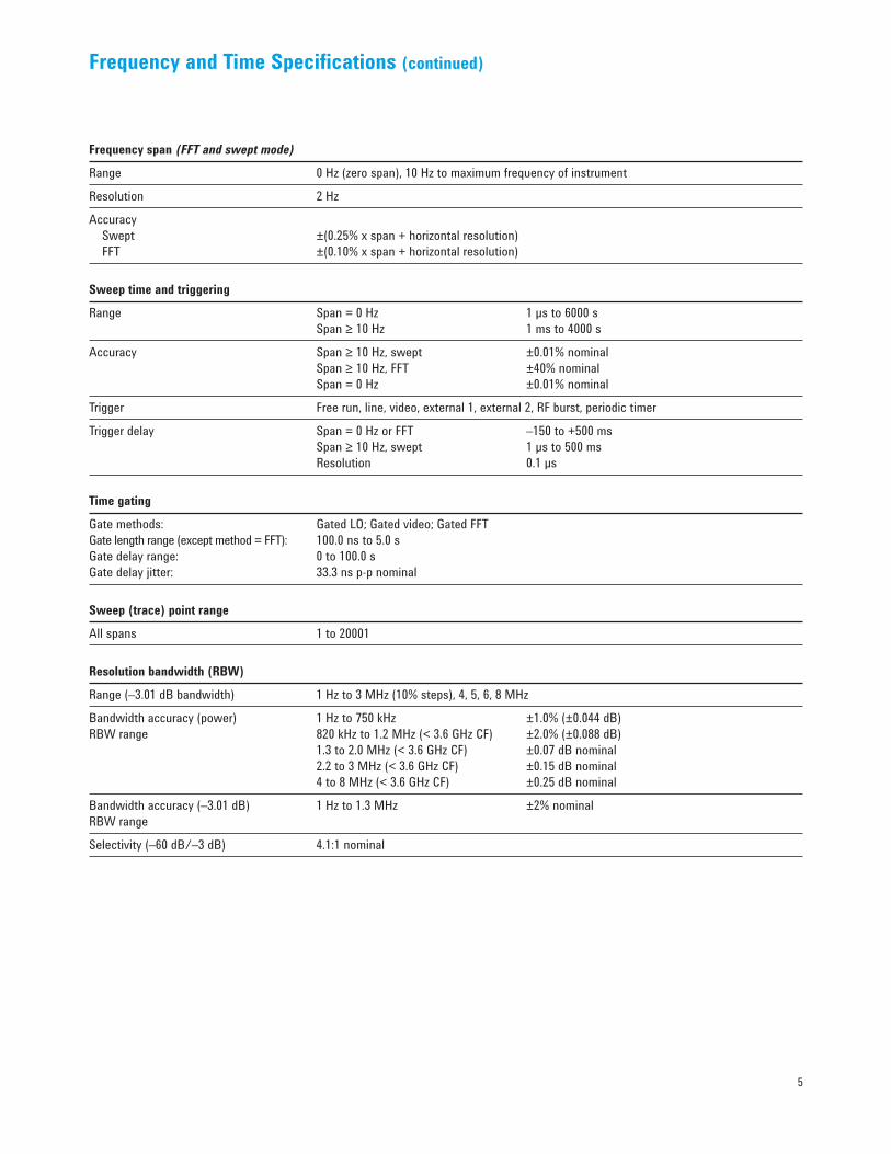
Frequency span (FFT and swept mode)
Range 0 Hz (zero span), 10 Hz to maximum frequency of instrument
Resolution 2 Hz
Accuracy Swept ±(0.25% x span + horizontal resolution) FFT ±(0.10% x span + horizontal resolution)
Sweep time and triggering
Range Span = 0 Hz 1 µs to 6000 s Span ≥ 10 Hz 1 ms to 4000 s
Accuracy Span ≥ 10 Hz, swept ±0.01% nominal Span ≥ 10 Hz, FFT ±40% nominal Span = 0 Hz ±0.01% nominal
Trigger Free run, line, video, external 1, external 2, RF burst, periodic timer
Trigger delay Span = 0 Hz or FFT –150 to +500 ms Span ≥ 10 Hz, swept 1 µs to 500 ms Resolution 0.1 µs
Time gating
Gate methods: Gated LO; Gated video; Gated FFTGate length range (except method = FFT): 100.0 ns to 5.0 sGate delay range: 0 to 100.0 sGate delay jitter: 33.3 ns p-p nominal
Sweep (trace) point range
All spans 1 to 20001
Resolution bandwidth (RBW)
Range (–3.01 dB bandwidth) 1 Hz to 3 MHz (10% steps), 4, 5, 6, 8 MHz
Bandwidth accuracy (power) 1 Hz to 750 kHz ±1.0% (±0.044 dB)RBW range 820 kHz to 1.2 MHz (< 3.6 GHz CF) ±2.0% (±0.088 dB) 1.3 to 2.0 MHz (< 3.6 GHz CF) ±0.07 dB nominal 2.2 to 3 MHz (< 3.6 GHz CF) ±0.15 dB nominal 4 to 8 MHz (< 3.6 GHz CF) ±0.25 dB nominal
Bandwidth accuracy (–3.01 dB) 1 Hz to 1.3 MHz ±2% nominalRBW range
Selectivity (–60 dB/–3 dB) 4.1:1 nominal
6
Frequency and Time Specifications (continued)
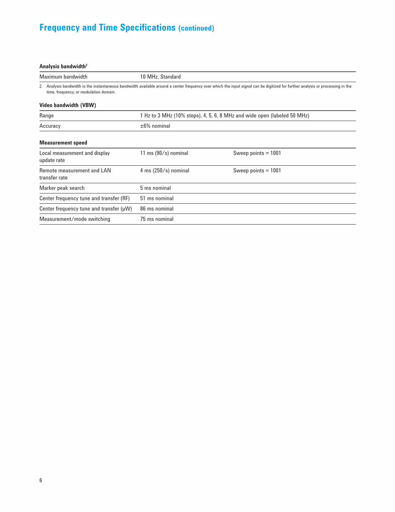
Analysis bandwidth2
Maximum bandwidth 10 MHz, Standard 2. Analysis bandwidth is the instantaneous bandwidth available around a center frequency over which the input signal can be digitized for further analysis or processing in the
time, frequency, or modulation domain.
Video bandwidth (VBW)
Range 1 Hz to 3 MHz (10% steps), 4, 5, 6, 8 MHz and wide open (labeled 50 MHz)
Accuracy ±6% nominal
Measurement speed
Local measurement and display 11 ms (90/s) nominal Sweep points = 1001 update rate
Remote measurement and LAN 4 ms (250/s) nominal Sweep points = 1001transfer rate
Marker peak search 5 ms nominal
Center frequency tune and transfer (RF) 51 ms nominal
Center frequency tune and transfer (µW) 86 ms nominal
Measurement/mode switching 75 ms nominal

7
Amplitude Accuracy and Range Specifications
Amplitude range
Measurement range Displayed average noise level (DANL) to +23 dBm
Input attenuator range (9 kHz to 26.5 GHz) Standard 0 to 60 dB in 10 dB steps Option FSA 0 to 60 dB in 2 dB steps
Electronic attenuator (Option EA3)
Frequency range 9 kHz to 3.6 GHz
Attenuation range Electronic attenuator range 0 to 24 dB, 1 dB steps Full attenuation range 0 to 84 dB, 1 dB steps (mechanical + electronic)
Maximum safe input level
Average total power +30 dBm (1 W)(with and without preamp)
Peak pulse power < 10 µs pulse width, < 1% duty cycle +50 dBm (100 W) and input attenuation ≥30 dB
DC volts DC coupled ±0.2 Vdc AC coupled ±70 Vdc
Display range
Log scale 0.1 to 1 dB/division in 0.1 dB steps 1 to 20 dB/division in 1 dB steps (10 display divisions)
Linear scale 10 divisions
Scale units dBm, dBmV, dBµV, dBmA, dBµA, V, W, A
8
Amplitude Accuracy and Range Specifications (continued)
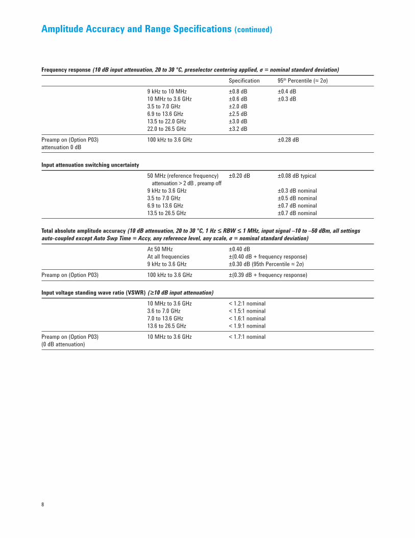
Frequency response (10 dB input attenuation, 20 to 30 °C, preselector centering applied, σ = nominal standard deviation)
Specification 95th Percentile (≈ 2σ)
9 kHz to 10 MHz ±0.8 dB ±0.4 dB 10 MHz to 3.6 GHz ±0.6 dB ±0.3 dB 3.5 to 7.0 GHz ±2.0 dB 6.9 to 13.6 GHz ±2.5 dB 13.5 to 22.0 GHz ±3.0 dB 22.0 to 26.5 GHz ±3.2 dB
Preamp on (Option P03) 100 kHz to 3.6 GHz ±0.28 dBattenuation 0 dB
Input attenuation switching uncertainty
50 MHz (reference frequency) ±0.20 dB ±0.08 dB typical attenuation > 2 dB , preamp off 9 kHz to 3.6 GHz ±0.3 dB nominal 3.5 to 7.0 GHz ±0.5 dB nominal 6.9 to 13.6 GHz ±0.7 dB nominal 13.5 to 26.5 GHz ±0.7 dB nominal
Total absolute amplitude accuracy (10 dB attenuation, 20 to 30 °C, 1 Hz ≤ RBW ≤ 1 MHz, input signal –10 to –50 dBm, all settings auto-coupled except Auto Swp Time = Accy, any reference level, any scale, σ = nominal standard deviation)
At 50 MHz ±0.40 dB At all frequencies ±(0.40 dB + frequency response) 9 kHz to 3.6 GHz ±0.30 dB (95th Percentile ≈ 2σ)
Preamp on (Option P03) 100 kHz to 3.6 GHz ±(0.39 dB + frequency response)
Input voltage standing wave ratio (VSWR) (≥10 dB input attenuation)
10 MHz to 3.6 GHz < 1.2:1 nominal 3.6 to 7.0 GHz < 1.5:1 nominal 7.0 to 13.6 GHz < 1.6:1 nominal 13.6 to 26.5 GHz < 1.9:1 nominal
Preamp on (Option P03) 10 MHz to 3.6 GHz < 1.7:1 nominal(0 dB attenuation)
9
Amplitude Accuracy and Range Specifications (continued)
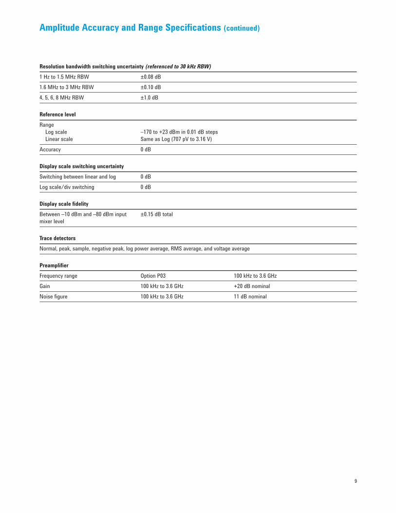
Resolution bandwidth switching uncertainty (referenced to 30 kHz RBW)
1 Hz to 1.5 MHz RBW ±0.08 dB
1.6 MHz to 3 MHz RBW ±0.10 dB
4, 5, 6, 8 MHz RBW ±1.0 dB
Reference level
Range Log scale –170 to +23 dBm in 0.01 dB steps Linear scale Same as Log (707 pV to 3.16 V)
Accuracy 0 dB
Display scale switching uncertainty
Switching between linear and log 0 dB
Log scale/div switching 0 dB
Display scale fidelity
Between –10 dBm and –80 dBm input ±0.15 dB totalmixer level
Trace detectors
Normal, peak, sample, negative peak, log power average, RMS average, and voltage average
Preamplifier
Frequency range Option P03 100 kHz to 3.6 GHz
Gain 100 kHz to 3.6 GHz +20 dB nominal
Noise figure 100 kHz to 3.6 GHz 11 dB nominal
10
Dynamic Range Specifications
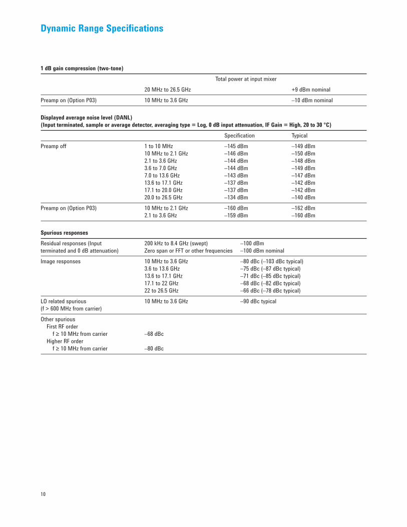
1 dB gain compression (two-tone)
Total power at input mixer
20 MHz to 26.5 GHz +9 dBm nominal
Preamp on (Option P03) 10 MHz to 3.6 GHz –10 dBm nominal
Displayed average noise level (DANL) (Input terminated, sample or average detector, averaging type = Log, 0 dB input attenuation, IF Gain = High, 20 to 30 °C)
Specification Typical
Preamp off 1 to 10 MHz –145 dBm –149 dBm 10 MHz to 2.1 GHz –146 dBm –150 dBm 2.1 to 3.6 GHz –144 dBm –148 dBm 3.6 to 7.0 GHz –144 dBm –149 dBm 7.0 to 13.6 GHz –143 dBm –147 dBm 13.6 to 17.1 GHz –137 dBm –142 dBm 17.1 to 20.0 GHz –137 dBm –142 dBm 20.0 to 26.5 GHz –134 dBm –140 dBm
Preamp on (Option P03) 10 MHz to 2.1 GHz –160 dBm –162 dBm 2.1 to 3.6 GHz –159 dBm –160 dBm
Spurious responses
Residual responses (Input 200 kHz to 8.4 GHz (swept) –100 dBmterminated and 0 dB attenuation) Zero span or FFT or other frequencies –100 dBm nominal
Image responses 10 MHz to 3.6 GHz –80 dBc (–103 dBc typical) 3.6 to 13.6 GHz –75 dBc (–87 dBc typical) 13.6 to 17.1 GHz –71 dBc (–85 dBc typical) 17.1 to 22 GHz –68 dBc (–82 dBc typical) 22 to 26.5 GHz –66 dBc (–78 dBc typical)
LO related spurious 10 MHz to 3.6 GHz –90 dBc typical(f > 600 MHz from carrier)
Other spurious First RF order f ≥ 10 MHz from carrier –68 dBc Higher RF order f ≥ 10 MHz from carrier –80 dBc

11
Dynamic Range Specifications (continued)
Nominal Range at 1 GHz
-130
-120
-110
-100
-90
-80
-70
-60
-80 -70 -60 -50 -40 -30 -20 -10Mixer Level (dBm)
DANL(1 Hz RBW)2nd HarmonicDistortion3rd OrderIntermodulation
rela
tive
to m
ixer
leve
l (dB
)
Figure 1. Nominal dynamic range – Band 0, for second and third order distortion, 9 kHz to 3.6 GHz
Nominal Dynamic Range Bands 1-4
-130
-120
-110
-100
-90
-80
-70
-60
-80 -70 -60 -50 -40 -30 -20 -10Mixer Level (dBm)
DANL
and
dist
ortio
n re
lativ
e to
mix
er le
vel (
dB)
DANL(1 Hz RBW)2nd HarmonicDistortion3rd OrderIntermodulation
22–26.5 GHz3.6–26.5 GHz 13.6–26.5 GHz
3.6–13.6 GHz 13.6–22 GHz
3.6–13.6 GHz
Figure 2. Nominal dynamic range – Bands 1 to 4, second and third order distortion, 3.6 GHz to 26.5 GHz
Second harmonic distortion (SHI)
Mixer level SHI 10 MHz to 1.8 GHz –15 dBm +45 dBm 1.8 to 7.0 GHz –15 dBm +65 dBm 7.0 to 11.0 GHz –15 dBm +55 dBm 11.0 to 13.25 GHz –15 dBm +50 dBm
Third-order intermodulation distortion (TOI) (two -30 dBm tones at input mixer with tone separation > 5 times IF prefilter bandwidth, 20 to 30 degC, see Specifications Guide for IF prefilter bandwidths)
Distortion TOI Typical 100 to 400 MHz –80 dBc +10 dBm +14 dBm 400 MHz to 1.7 GHz –82 dBc +11 dBm +15 dBm 1.7 to 3.6 GHz –86 dBc +13 dBm +17 dBm 3.6 to 7.0 GHz –82 dBc +11 dBm +15 dBm 7.0 to 13.6 GHz –82 dBc +11 dBm +15 dBm 13.6 to 26.5 GHz –78 dBc + 9 dBm +14 dBm
Preamp on (Option P03) 30 MHz to 3.6 GHz 0 dBm nominal (two –45 dBm tones at preamp input)

12
Dynamic Range Specifications (continued)
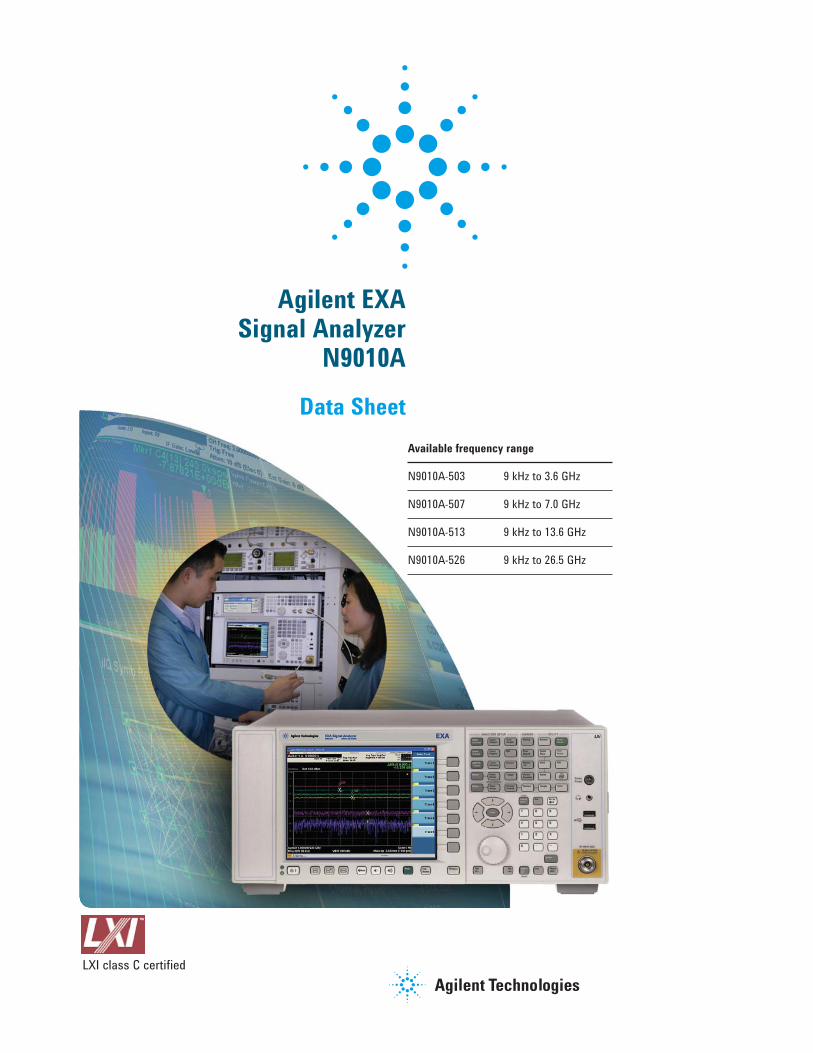
Phase noise3
Noise sidebands Offset Specification Typical(20 to 30 °C, CF = 1 GHz) 100 Hz –84 dBc/Hz – 88 dBc/Hz 1 kHz – 97 dBc/Hz nominal 10 kHz –99 dBc/Hz –103 dBc/Hz 100 kHz –111 dBc/Hz –114 dBc/Hz 1 MHz –130 dBc/Hz –134 dBc/Hz 10 MHz –143 dBc/Hz nominal3. For nominal values, refer to Figure 3.
Nominal phase noise at different center frequencies with RBW selectivity curvesOptimized phase noise, versus offset frequency
–20–30–40–50–60–70–80–90
–100–110–120–130–140–150–160–170
0.01 0.1 1 10 100 1000 10000Freq (kHz)
SSB
phas
e no
ise (d
Bc/H
z)
RBW = 100 HzRBW = 1 kHz
RBW = 1 kHzRBW = 100 kHz
CF = 600 MHz
CF = 10.2 GHz
CF = 25.2 GHz
Figure 3. Nominal phase noise at different center frequencies (with Option PFR)
13
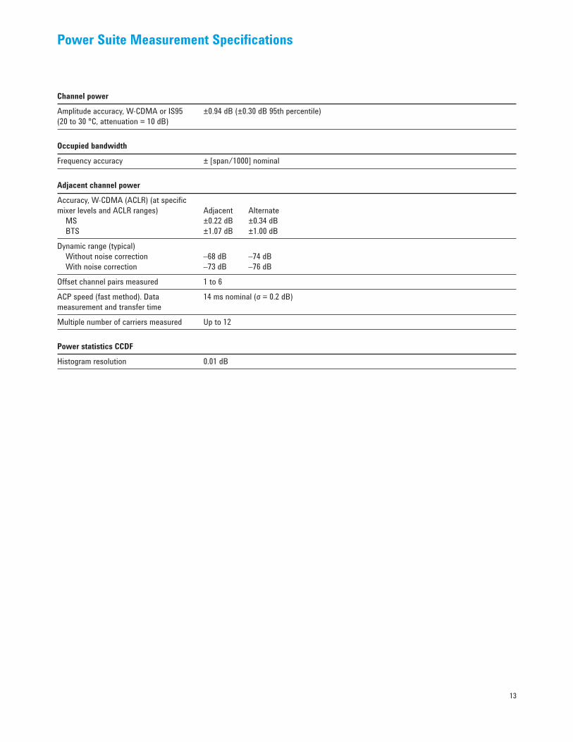
Power Suite Measurement Specifications
Channel power
Amplitude accuracy, W-CDMA or IS95 ±0.94 dB (±0.30 dB 95th percentile)(20 to 30 °C, attenuation = 10 dB)
Occupied bandwidth
Frequency accuracy ± [span/1000] nominal
Adjacent channel power
Accuracy, W-CDMA (ACLR) (at specific mixer levels and ACLR ranges) Adjacent Alternate MS ±0.22 dB ±0.34 dB BTS ±1.07 dB ±1.00 dB
Dynamic range (typical) Without noise correction –68 dB –74 dB With noise correction –73 dB –76 dB
Offset channel pairs measured 1 to 6
ACP speed (fast method). Data 14 ms nominal (σ = 0.2 dB)measurement and transfer time
Multiple number of carriers measured Up to 12
Power statistics CCDF
Histogram resolution 0.01 dB
14
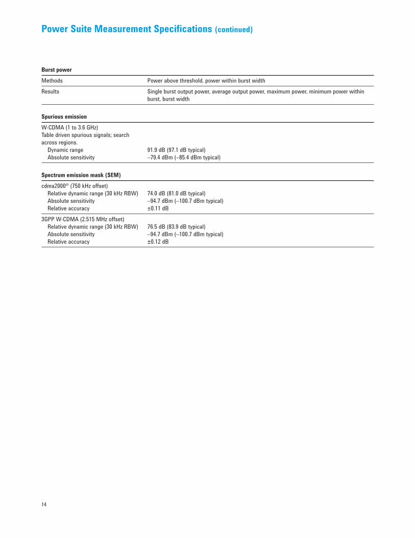
Power Suite Measurement Specifications (continued)
Burst power
Methods Power above threshold, power within burst width
Results Single burst output power, average output power, maximum power, minimum power within burst, burst width
Spurious emission
W-CDMA (1 to 3.6 GHz) Table driven spurious signals; search across regions. Dynamic range 91.9 dB (97.1 dB typical) Absolute sensitivity –79.4 dBm (–85.4 dBm typical)
Spectrum emission mask (SEM)
cdma2000® (750 kHz offset) Relative dynamic range (30 kHz RBW) 74.0 dB (81.0 dB typical) Absolute sensitivity –94.7 dBm (–100.7 dBm typical) Relative accuracy ±0.11 dB
3GPP W-CDMA (2.515 MHz offset) Relative dynamic range (30 kHz RBW) 76.5 dB (83.9 dB typical) Absolute sensitivity –94.7 dBm (–100.7 dBm typical) Relative accuracy ±0.12 dB

15
General Specifications
Temperature range
Operating 5 to +50 °C
Storage –40 to +65 °C
EMC
Complies with European EMC Directive 89/336/EEC, amended by 93/68/EEC • IEC/EN 61326 • CISPR Pub 11 Group 1, class A • AS/NZS CISPR 11:2002 • ICES/NMB-001
Safety
Complies with European Low Voltage Directive 73/23/EEC, amended by 93/68/EEC • IEC/EN 61010-1 • Canada: CSA C22.2 No. 61010-1 • USA: UL 61010-1
Audio noise
Acoustic noise emission Geraeuschemission
LpA <70 dB LpA <70 dB
Operator position Am Arbeitsplatz
Normal position Normaler Betrieb
Per ISO 7779 Nach DIN 45635 t.19
Environmental stress
Samples of this product have been type tested in accordance with the Agilent Environmental Test Manual and verified to be robust against the environmental stresses of storage, transportation and end-use; those stresses include but are not limited to temperature, humidity, shock, vibration, altitude and power line conditions. Test methods are aligned with IEC 60068-2 and levels are similar to MIL-PRF-28800F Class 3.

16
General Specifications (continued)
Power requirements
Voltage and frequency (nominal) 100/120 V, 50/60 Hz 220/240 V, 50/60 Hz
Power consumption On < 260 watts Standby < 20 watts
Data storage
Internal 40 GB nominal
External Supports USB 2.0 compatible memory devices
Weight (without options)
Net 16 kg (35 lbs) nominalShipping 28 kg (62 lbs) nominal
Dimensions
Height 177 mm (7.0 in)
Width 426 mm (16.8 in)
Length 368 mm (14.5 in)
Warranty
The EXA signal analyzer is supplied with a one-year warranty.
Calibration cycle
The recommended calibration cycle is one year. Calibration services are available through Agilent service centers.

17
Inputs and Outputs
Front panel
RF input Connector Type-N female, 50 Ω nominal
Probe power Voltage/current +15 Vdc, ±7% at 150 mA max nominal –12.6 Vdc, ±10% at 150 mA max nominal
USB 2.0 ports Master (2 ports) Standard Compatible with USB 2.0 Connector USB Type-A female Output current 0.5 A nominal
Rear panel
10 MHz out Connector BNC female, 50 Ω nominal Output amplitude ≥ 0 dBm nominal Frequency 10 MHz ± (10 MHz x frequency reference accuracy)
Ext Ref In Connector BNC female, 50 Ω nominal Input amplitude range –5 to +10 dBm nominal Input frequency 10 MHz nominal Frequency lock range ± 5 x 10⁻⁶ of specified external reference input frequency
Trigger 1 and trigger 2 inputs Connector BNC female Impedance > 10 kΩ nominal Trigger level range –5 to +5 V
Trigger 1 and trigger 2 outputs Connector BNC female Impedance 50 Ω nominal Level 5 V TTL nominal
18
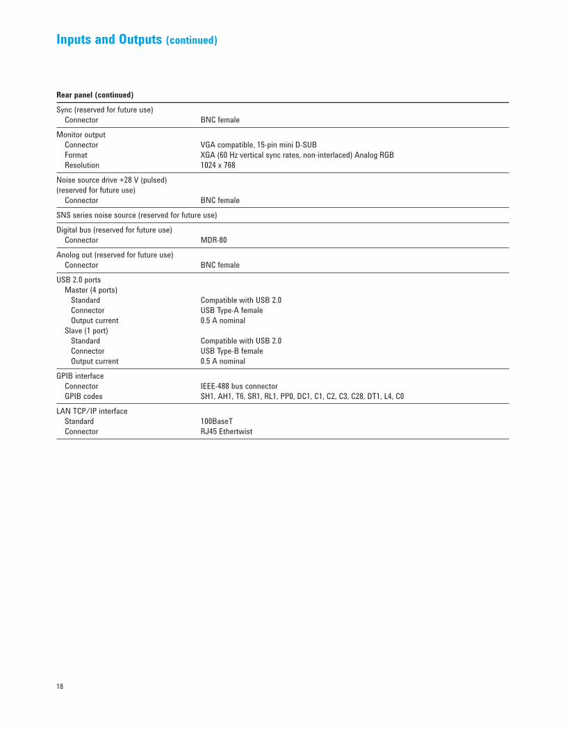
Inputs and Outputs (continued)
Rear panel (continued)
Sync (reserved for future use) Connector BNC female
Monitor output Connector VGA compatible, 15-pin mini D-SUB Format XGA (60 Hz vertical sync rates, non-interlaced) Analog RGB Resolution 1024 x 768
Noise source drive +28 V (pulsed) (reserved for future use) Connector BNC female
SNS series noise source (reserved for future use)
Digital bus (reserved for future use) Connector MDR-80
Anolog out (reserved for future use) Connector BNC female
USB 2.0 ports Master (4 ports) Standard Compatible with USB 2.0 Connector USB Type-A female Output current 0.5 A nominal Slave (1 port) Standard Compatible with USB 2.0 Connector USB Type-B female Output current 0.5 A nominal
GPIB interface Connector IEEE-488 bus connector GPIB codes SH1, AH1, T6, SR1, RL1, PP0, DC1, C1, C2, C3, C28, DT1, L4, C0
LAN TCP/IP interface Standard 100BaseT Connector RJ45 Ethertwist
19
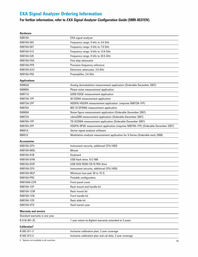
EXA Signal Analyzer Ordering InformationFor further information, refer to EXA Signal Analyzer Configuration Guide (5989-6531EN)
HardwareN9010A EXA signal analyzerN9010A-503 Frequency range, 9 kHz to 3.6 GHzN9010A-507 Frequency range, 9 kHz to 7.0 GHzN9010A-513 Frequency range, 9 kHz to 13.6 GHzN9010A-526 Frequency range, 9 kHz to 26.5 GHzN9010A-FSA Fine step attenuatorN9010A-PFR Precision frequency referenceN9010A-EA3 Electronic attenuator, 3.6 GHzN9010A-P03 Preamplifier, 3.6 GHz
Applications N9063A Analog demodulation measurement application (Orderable December 2007)N9068A Phase noise measurement applicationN9071A GSM/EDGE measurement applicationN9073A-1FP W-CDMA measurement application N9073A-2FP HSDPA/HSUPA measurement application (requires N9073A-1FP)N9075A 802.16 OFDMA measurement application N9069A Noise fi gure measurement application (Orderable December 2007)N9072A cdma2000 measurement application (Orderable December 2007)N9079A-1FP TD-SCDMA measurement application (Orderable December 2007)N9079A-2FP HSDPA/8PSK measurement application (requires N9079A-1FP) (Orderable December 2007)89601A Vector signal analysis software 89601X Modulation analysis measurement application for X-Series (Orderable early 2008)
AccessoriesN9010A-CPU Instrument security, additional CPU/HDDN9010A-MSE MouseN9010A-KYB KeyboardN9010A-EFM USB flash drive, 512 MBN9010A-DVR USB DVD-ROM/CD-R/RW driveN9010A-CPU Instrument security, additional CPU/HDDN9010A-MLP Minimum loss pad, 50 to 75 ΩN9010A-PRC Portable configurationN9010AK-CVR Front panel coverN9010A-1CP Rack mount and handle kitN9010A-1CM Rack mount kitN9010A-1CN Front handle kitN9010A-1CR Rack slide kitN9010A-HTC Hard transit case
Warranty and serviceStandard warranty is one year.R-51B-001-3C 1 year return-to-Agilent warranty extended to 3 years
Calibration4
R-50C-011-3 Inclusive calibration plan, 3 year coverageR-50C-013-3 Inclusive calibration plan and cal data, 3 year coverage4. Options not available in all countries
20
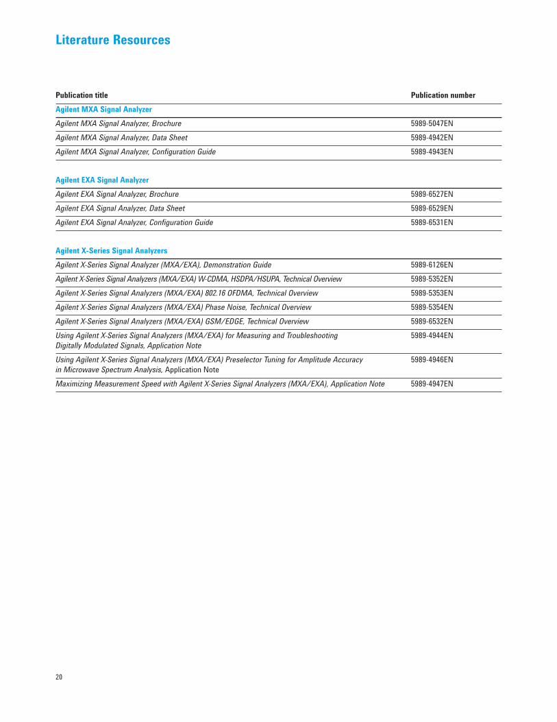
Literature Resources
Publication title Publication numberAgilent MXA Signal Analyzer Agilent MXA Signal Analyzer, Brochure 5989-5047ENAgilent MXA Signal Analyzer, Data Sheet 5989-4942ENAgilent MXA Signal Analyzer, Configuration Guide 5989-4943EN
Agilent EXA Signal AnalyzerAgilent EXA Signal Analyzer, Brochure 5989-6527ENAgilent EXA Signal Analyzer, Data Sheet 5989-6529ENAgilent EXA Signal Analyzer, Configuration Guide 5989-6531EN
Agilent X-Series Signal AnalyzersAgilent X-Series Signal Analyzer (MXA/EXA), Demonstration Guide 5989-6126ENAgilent X-Series Signal Analyzers (MXA/EXA) W-CDMA, HSDPA/HSUPA, Technical Overview 5989-5352ENAgilent X-Series Signal Analyzers (MXA/EXA) 802.16 OFDMA, Technical Overview 5989-5353ENAgilent X-Series Signal Analyzers (MXA/EXA) Phase Noise, Technical Overview 5989-5354EN Agilent X-Series Signal Analyzers (MXA/EXA) GSM/EDGE, Technical Overview 5989-6532EN Using Agilent X-Series Signal Analyzers (MXA/EXA) for Measuring and Troubleshooting 5989-4944EN Digitally Modulated Signals, Application NoteUsing Agilent X-Series Signal Analyzers (MXA/EXA) Preselector Tuning for Amplitude Accuracy 5989-4946EN in Microwave Spectrum Analysis, Application NoteMaximizing Measurement Speed with Agilent X-Series Signal Analyzers (MXA/EXA), Application Note 5989-4947EN

www.agilent.com/fi nd/emailupdatesGet the latest information on the products and applications you select.
www.agilent.com/fi nd/agilentdirectQuickly choose and use your test equipment solutions with confi dence.
Remove all doubtOur repair and calibration services will get your equipment back to you, performing like new, when prom-ised. You will get full value out of your Agilent equipment through-out its lifetime. Your equipment will be serviced by Agilent-trained technicians using the latest factory calibration procedures, automated repair diagnostics and genuine parts. You will always have the utmost confi dence in your measurements.
Agilent offers a wide range of addi-tional expert test and measurement services for your equipment, includ-ing initial start-up assistance onsite education and training, as well as design, system integration, and project management.
For more information on repair and calibration services, go to:
www.agilent.com/fi nd/openAgilent Open simplifi es the processof connecting and programmingtest systems to help engineersdesign, validate and manufacture electronic products. Agilent offersopen connectivity for a broad range of system-ready instruments, open industry software, PC-standard I/O and global support, which are combined to more easily integrate test system development.
www.lxistandard.orgLXI is the LAN-based successor to GPIB, providing faster, more effi cient connectivity. Agilent is a founding member of the LXI consortium.
www.agilent.com/fi nd/removealldoubt
Microsoft® and Windows® are U.S. registered trademarks of Microsoft Corporation.
Pentium® is a U.S. registered trademark ofIntel Corporation.
cdma2000 is a registered certifi cation mark of the Telecommunications Industry Association. Used under license.
WiMax, Mobile WiMax, or WiMax Forum are trademarks of the WiMax Forum.
www.agilent.comFor more information on Agilent Technologies’ products, applications or services, please contact your local Agilent offi ce. The complete list is available at:www.agilent.com/fi nd/contactus
AmericasCanada (877) 894-4414Latin America 305 269 7500United States (800) 829-4444
Asia Pacifi cAustralia 1 800 629 485China 800 810 0189Hong Kong 800 938 693India 1 800 112 929Japan 81 426 56 7832Korea 080 769 0800Malaysia 1 800 888 848Singapore 1 800 375 8100Taiwan 0800 047 866Thailand 1 800 226 008
EuropeAustria 0820 87 44 11Belgium 32 (0) 2 404 93 40 Denmark 45 70 13 15 15Finland 358 (0) 10 855 2100France 0825 010 700Germany 01805 24 6333* *0.14€/minuteIreland 1890 924 204Italy 39 02 92 60 8484Netherlands 31 (0) 20 547 2111Spain 34 (91) 631 3300Sweden 0200-88 22 55Switzerland (French) 41 (21) 8113811(Opt 2)Switzerland (German) 0800 80 53 53 (Opt 1)United Kingdom 44 (0) 118 9276201Other European Countries: www.agilent.com/fi nd/contactusRevised: May 7, 2007
Product specifi cations and descriptions in this document subject to change without notice.
© Agilent Technologies, Inc. 2007Printed in USA, August 29, 20075989-6529EN