Agilent E3631A DC Power Supply - University of … · Tri pl e output E as y-to- us e ... (see...
111
Service Guide Part Number: E3631-90011 October 2007 For warranty information, refer to the back of the manual. ©Copyright Agilent Technologies, Inc. 2000-2007 All Rights Reserved. Agilent E3631A DC Power Supply
Transcript of Agilent E3631A DC Power Supply - University of … · Tri pl e output E as y-to- us e ... (see...
Service Guide
Part Number: E3631-90011October 2007
For warranty information, refer to the back of the manual.
©Copyright Agilent Technologies, Inc. 2000-2007All Rights Reserved.
Agilent E3631ADC Power Supply
The Agilent Technologies E3631A is a high performance 80 watt-triple output
DC power supply with GPIB and RS-232 interfaces. The combination of bench-
top and system features in this power supply provides versatile solutions for
your design and test requirements.
Convenient bench-top features
• Triple output
• Easy-to-use knob control for voltage and current settings
• Highly visible vacuum-fluorescent display for voltage and current meters
• Tracking operation for ±25V outputs
• Excellent load and line regulation and low ripple and noise
• Operating states storage
• Portable, ruggedized case with non-skid feet
Flexible system features
• GPIB (IEEE-488) and RS-232 interfaces are standard
• SCPI (Standard Commands for Programmable Instruments) compatibility
• I/O setup easily done from front-panel
Agilent E3631A Triple Output DC Power Supply
3
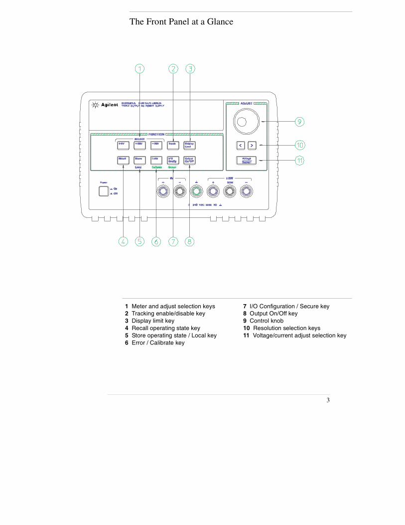
The Front Panel at a Glance
1 Meter and adjust selection keys2 Tracking enable/disable key3 Display limit key4 Recall operating state key5 Store operating state / Local key6 Error / Calibrate key
7 I/O Configuration / Secure key8 Output On/Off key9 Control knob10 Resolution selection keys11 Voltage/current adjust selection key
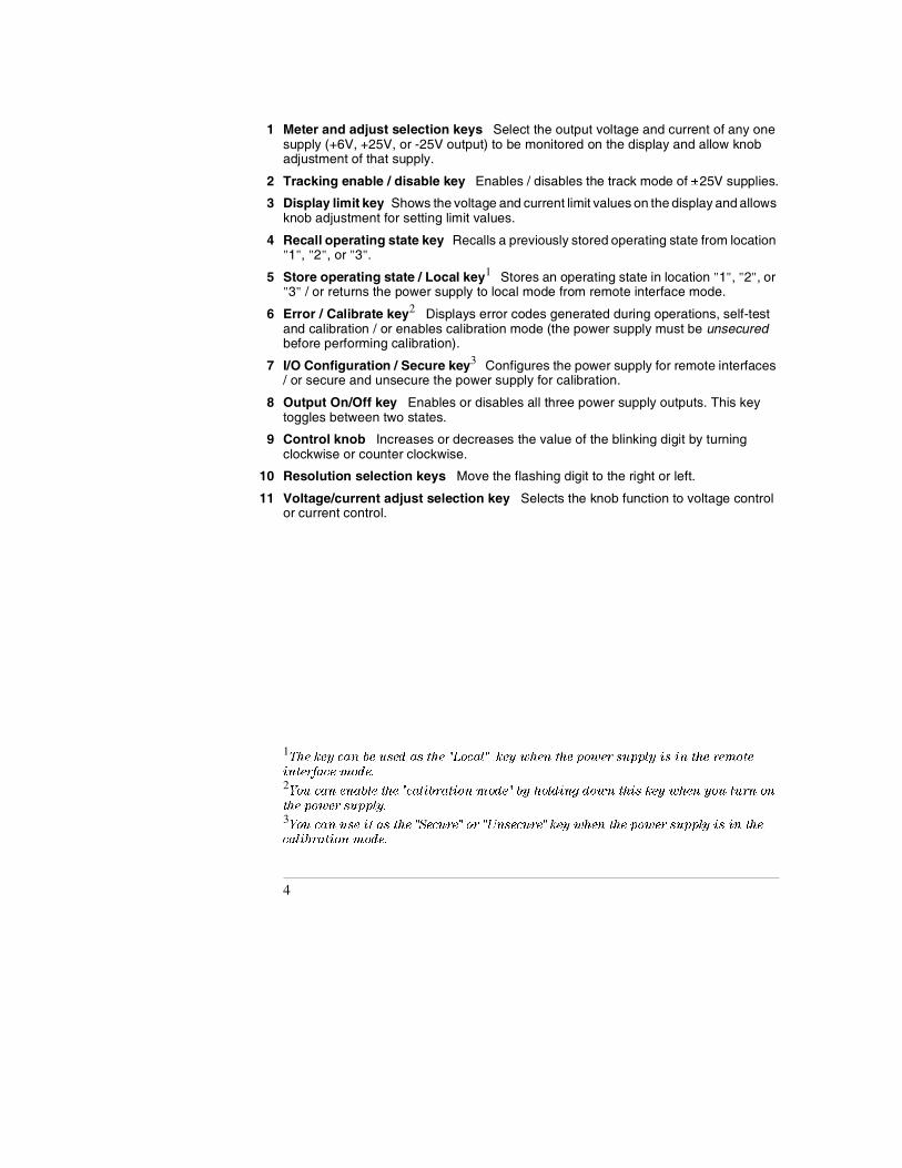
1 Meter and adjust selection keys Select the output voltage and current of any one supply (+6V, +25V, or -25V output) to be monitored on the display and allow knob adjustment of that supply.
2 Tracking enable / disable key Enables / disables the track mode of ±25V supplies.
3 Display limit key Shows the voltage and current limit values on the display and allows knob adjustment for setting limit values.
4 Recall operating state key Recalls a previously stored operating state from location "1", "2", or "3".
5 Store operating state / Local key1 Stores an operating state in location "1", "2", or "3" / or returns the power supply to local mode from remote interface mode.
6 Error / Calibrate key2 Displays error codes generated during operations, self-test and calibration / or enables calibration mode (the power supply must be unsecured before performing calibration).
7 I/O Configuration / Secure key3 Configures the power supply for remote interfaces / or secure and unsecure the power supply for calibration.
8 Output On/Off key Enables or disables all three power supply outputs. This key toggles between two states.
9 Control knob Increases or decreases the value of the blinking digit by turning clockwise or counter clockwise.
10 Resolution selection keys Move the flashing digit to the right or left.
11 Voltage/current adjust selection key Selects the knob function to voltage control or current control.
1The key can be used as the "Local" key when the power supply is in the remote
interface mode.2You can enable the "calibration mode" by holding down this key when you turn on
the power supply.3You can use it as the "Secure" or "Unsecure" key when the power supply is in the
calibration mode.
4
Front-Panel Voltage and Current Settings
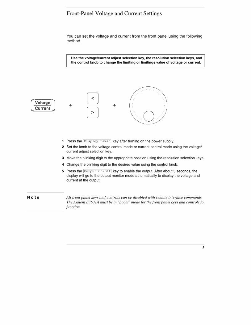
You can set the voltage and current from the front panel using the following method.
1 Press the key after turning on the power supply.
2 Set the knob to the voltage control mode or current control mode using the voltage/current adjust selection key.
3 Move the blinking digit to the appropriate position using the resolution selection keys.
4 Change the blinking digit to the desired value using the control knob.
5 Press the key to enable the output. After about 5 seconds, the display will go to the output monitor mode automatically to display the voltage and current at the output.
N o t e All front panel keys and controls can be disabled with remote interface commands. The Agilent E3631A must be in "Local" mode for the front panel keys and controls to function.
Use the voltage/current adjust selection key, the resolution selection keys, and the control knob to change the limiting or limitings value of voltage or current.
Display Limit
Output On/Off
5

6
Display Annunciators
Adrs Power supply is addressed to listen or talk over a remote interface.
Rmt Power supply is in remote interface mode.
+6V Displays the output voltage and current for +6V supply. Knob is active for 6V supply.
+25V Displays the output voltage and current for +25V supply. Knob is active for +25V supply.
-25V Displays the output voltage and current for -25V supply. Knob is active for -25V supply
CAL Power Supply is calibration mode.
Track The output of +25V and -25V supplies are in track mode.
Lmt The display shows the voltage and current limit values of a selectedsupply.
ERROR Hardware or remote interface command errors are detected and also the error bit has not been cleared.
OFF The three output of the power supply is disabled.
Unreg The displayed output is unregulated (output is neither CV nor CC).
CV The displayed output is in constant-voltage mode.
CC The displayed output is in constant-current mode.
To review the display annunciators, hold down key as you turn on the power supply.
Display Limit
7
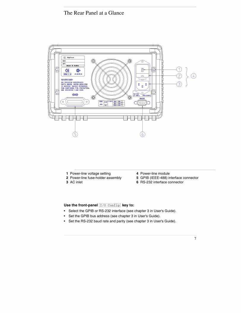
The Rear Panel at a Glance
Use the front-panel key to:
• Select the GPIB or RS-232 interface (see chapter 3 in User's Guide).
• Set the GPIB bus address (see chapter 3 in User's Guide).
• Set the RS-232 baud rate and parity (see chapter 3 in User's Guide).
1 Power-line voltage setting2 Power-line fuse-holder assembly3 AC inlet
4 Power-line module5 GPIB (IEEE-488) interface connector6 RS-232 interface connector
I/O Config
In This Book
Specifications Chapter 1 lists the power supply’s specifications and
describes how to interpret these specifications.
Quick Start Chapter 2 prepares the power supply for use and helps you get
familiar with the front-panel features.
Calibration Procedures Chapter 3 provides performance verification and
calibration procedures.
Theory of Operation Chapter 4 describes block and circuit level theory
related to the operation of the power supply.
Service Chapter 5 provides guidelines for returning your power supply to
Agilent Technologies for servicing, or for servicing it yourself.
Replaceable Parts Chapter 6 contains a detailed parts list of the power
supply.
Backdating Chapter 7 describes the difference between this manual and
older issues of this manual.
Schematics Chapter 8 contains the power supply's schematics, disassembly
drawings, and component locator drawings.
If you have questions relating to the operation of the power supply, call 1-800-829-4444 in the United States, or contact your nearest Agilent
Technologies Sales Office.
8
Co
nten
ts
Contents
Chapter 1 Specifications
Performance Specifications - - - - - - - - - - - - - - - - - - - - - - - - - - - - - 15
Supplemental Characteristics - - - - - - - - - - - - - - - - - - - - - - - - - - - 17
Chapter 2 Quick Start
To prepare the power supply for use- - - - - - - - - - - - - - - - - - - - - - 23
To check the rated voltages of the power supply - - - - - - - - - - - - 25
To check the rated currents of the power supply - - - - - - - - - - - - 27
To use the power supply in constant voltage mode - - - - - - - - - - 29
To use the power supply in constant current mode - - - - - - - - - - 31
To use the power supply in track mode- - - - - - - - - - - - - - - - - - - - 33
To store and recall the instrument state - - - - - - - - - - - - - - - - - - - 34
To rack mount the power supply - - - - - - - - - - - - - - - - - - - - - - - - - 36
Chapter 3 Calibration Procedures
Agilent Technologies Calibration Services - - - - - - - - - - - - - - - - - 41
Calibration Interval - - - - - - - - - - - - - - - - - - - - - - - - - - - - - - - - - - - - 41
Automating Calibration Procedures - - - - - - - - - - - - - - - - - - - - - - 42
Recommended Test Equipment - - - - - - - - - - - - - - - - - - - - - - - - - - 42
Test Considerations - - - - - - - - - - - - - - - - - - - - - - - - - - - - - - - - - - - 43
Performance Verification Tests - - - - - - - - - - - - - - - - - - - - - - - - - - 44
Self-Test - - - - - - - - - - - - - - - - - - - - - - - - - - - - - - - - - - - - - - - - - - - 44
Performance Verification Tests- - - - - - - - - - - - - - - - - - - - - - - - - 44
Measurement Techniques- - - - - - - - - - - - - - - - - - - - - - - - - - - - - - - 45
Setup for Most Tests - - - - - - - - - - - - - - - - - - - - - - - - - - - - - - - - - 45
Electronic Load - - - - - - - - - - - - - - - - - - - - - - - - - - - - - - - - - - - - - 46
Current-Monitoring Resistor - - - - - - - - - - - - - - - - - - - - - - - - - - - 46
Programming - - - - - - - - - - - - - - - - - - - - - - - - - - - - - - - - - - - - - - - 46
Voltage and Current Values - - - - - - - - - - - - - - - - - - - - - - - - - - - - 46
Constant Voltage (CV) Verifications - - - - - - - - - - - - - - - - - - - - - - 47
Constant Voltage Test Setup - - - - - - - - - - - - - - - - - - - - - - - - - - - 47
Voltage Programming and Readback Accuracy - - - - - - - - - - - - 47
CV Load Regulation - - - - - - - - - - - - - - - - - - - - - - - - - - - - - - - - - - 49
CV Line Regulation- - - - - - - - - - - - - - - - - - - - - - - - - - - - - - - - - - - 50
Normal Mode Voltage Noise (CV Ripple and Noise) - - - - - - - - 51
Common Mode Current Noise- - - - - - - - - - - - - - - - - - - - - - - - - - 52
Load Transient Response Time - - - - - - - - - - - - - - - - - - - - - - - - - 53
9
Contents
Chapter 3 Calibration Procedures (continued)
Constant Current (CC) Verifications - - - - - - - - - - - - - - - - - - - - - - 54
Constant Current Test Setup - - - - - - - - - - - - - - - - - - - - - - - - - - - 54
Current Programming and Readback Accuracy - - - - - - - - - - - - 54
CC Load Regulation - - - - - - - - - - - - - - - - - - - - - - - - - - - - - - - - - - 56
CC Line Regulation - - - - - - - - - - - - - - - - - - - - - - - - - - - - - - - - - - - 57
Normal Mode Current Noise (CC Ripple and Noise) - - - - - - - - 58
Performance Test Record for Agilent E3631A - - - - - - - - - - - - - - - 59
CV Performance Test Record- - - - - - - - - - - - - - - - - - - - - - - - - - - 59
CC Performance Test Record- - - - - - - - - - - - - - - - - - - - - - - - - - - 60
Calibration Security Code - - - - - - - - - - - - - - - - - - - - - - - - - - - - - - - 61
To Unsecure the Power Supply for Calibration - - - - - - - - - - - - 62
To Unsecure the Power Supply Without the Security Code - - - 64
Calibration Count - - - - - - - - - - - - - - - - - - - - - - - - - - - - - - - - - - - - - 65
Calibration Message - - - - - - - - - - - - - - - - - - - - - - - - - - - - - - - - - - - 65
General Calibration/Adjustment Procedure- - - - - - - - - - - - - - - - - 66
Aborting a Calibration in Progress - - - - - - - - - - - - - - - - - - - - - - - - 71
Calibration Record for Agilent E3631A - - - - - - - - - - - - - - - - - - - - 72
Error Messages - - - - - - - - - - - - - - - - - - - - - - - - - - - - - - - - - - - - - - - 73
Calibration Program - - - - - - - - - - - - - - - - - - - - - - - - - - - - - - - - - - - 75
Chapter 4 Theory of Operation
Block Diagram Overview - - - - - - - - - - - - - - - - - - - - - - - - - - - - - - - 81
AC Input and Bias Supplies- - - - - - - - - - - - - - - - - - - - - - - - - - - - - - 83
Floating Logic - - - - - - - - - - - - - - - - - - - - - - - - - - - - - - - - - - - - - - - - 84
D-to-A Converter - - - - - - - - - - - - - - - - - - - - - - - - - - - - - - - - - - - - - - 86
A-to-D Converter - - - - - - - - - - - - - - - - - - - - - - - - - - - - - - - - - - - - - - 87
Power Mesh and Control- - - - - - - - - - - - - - - - - - - - - - - - - - - - - - - - 88
Earth-Referenced Logic - - - - - - - - - - - - - - - - - - - - - - - - - - - - - - - - 90
Front Panel - - - - - - - - - - - - - - - - - - - - - - - - - - - - - - - - - - - - - - - - - - 90
Chapter 5 Service
Operating Checklist- - - - - - - - - - - - - - - - - - - - - - - - - - - - - - - - - - - - 93
Is the Power Supply Inoperative? - - - - - - - - - - - - - - - - - - - - - - - 93
Does the Power Supply Fail Self-Test? - - - - - - - - - - - - - - - - - - - 93
Types of Service Available - - - - - - - - - - - - - - - - - - - - - - - - - - - - - - 94
Standard Repair Service (worldwide) - - - - - - - - - - - - - - - - - - - - 94
Express Exchange (U.S.A. only) - - - - - - - - - - - - - - - - - - - - - - - - 94
10
Contents
Co
nten
ts
Chapter 5 Service (continued)Repacking for Shipment - - - - - - - - - - - - - - - - - - - - - - - - - - - - - - - - 95
Electrostatic Discharge (ESD) Precautions - - - - - - - - - - - - - - - - 96
Surface Mount Repair- - - - - - - - - - - - - - - - - - - - - - - - - - - - - - - - - - 96
To Replace the Power-Line Fuse - - - - - - - - - - - - - - - - - - - - - - - - - 96
Troubleshooting Hints - - - - - - - - - - - - - - - - - - - - - - - - - - - - - - - - - 97
Unit is Inoperative - - - - - - - - - - - - - - - - - - - - - - - - - - - - - - - - - - - 97
Unit Reports Errors 740 to 748 - - - - - - - - - - - - - - - - - - - - - - - - - 97
Unit Fails Self-Test- - - - - - - - - - - - - - - - - - - - - - - - - - - - - - - - - - - 97
Bias Supplies Problems - - - - - - - - - - - - - - - - - - - - - - - - - - - - - - - 98
Self-Test Procedures- - - - - - - - - - - - - - - - - - - - - - - - - - - - - - - - - - - 99
Power-On Self-Test - - - - - - - - - - - - - - - - - - - - - - - - - - - - - - - - - - 99
Complete Self-Test- - - - - - - - - - - - - - - - - - - - - - - - - - - - - - - - - - - 99
Chapter 6 Schematics
E3631-60002 Component Locator - - - - - - - - - - - - - - - - - - - - - - - 105
E3631-60003 Component Locator - - - - - - - - - - - - - - - - - - - - - - - 106
E3631-60004 Component Locator - - - - - - - - - - - - - - - - - - - - - - - 107
11

Contents
12
1
1
Specifications

Specifications
The performance specifications are listed in the following pages. Specifications
are warranted in the temperature range of 0 to 40°C with a resistive load.
Supplemental characteristics, which are not warranted but are descriptions of
performance determined either by design or testing. Chapter 3 "Calibration
Procedures" contains procedures for verifying the performance specifications.
All specifications apply to the three outputs unless otherwise specified.
14
Chapter 1 Specifications Performance Specifications
1
Performance Specifications
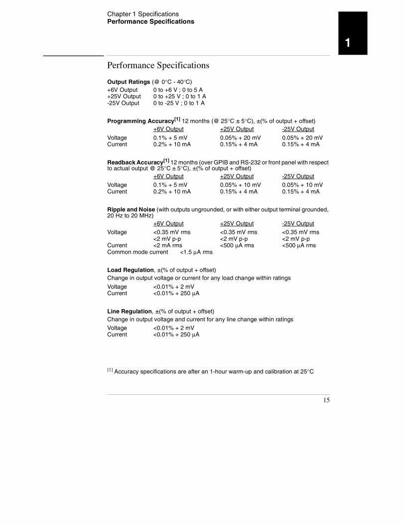
Output Ratings (@ 0°C - 40°C)+6V Output 0 to +6 V ; 0 to 5 A+25V Output 0 to +25 V ; 0 to 1 A-25V Output 0 to -25 V ; 0 to 1 A
Programming Accuracy[1] 12 months (@ 25°C ± 5°C), ±(% of output + offset)+6V Output +25V Output -25V Output
Voltage 0.1% + 5 mV 0.05% + 20 mV 0.05% + 20 mVCurrent 0.2% + 10 mA 0.15% + 4 mA 0.15% + 4 mA
Readback Accuracy[1] 12 months (over GPIB and RS-232 or front panel with respect to actual output @ 25°C ± 5°C), ±(% of output + offset)
+6V Output +25V Output -25V Output
Voltage 0.1% + 5 mV 0.05% + 10 mV 0.05% + 10 mVCurrent 0.2% + 10 mA 0.15% + 4 mA 0.15% + 4 mA
Ripple and Noise (with outputs ungrounded, or with either output terminal grounded, 20 Hz to 20 MHz)
+6V Output +25V Output -25V Output
Voltage <0.35 mV rms <0.35 mV rms <0.35 mV rms<2 mV p-p <2 mV p-p <2 mV p-p
Current <2 mA rms <500 μA rms <500 μA rmsCommon mode current <1.5 μA rms
Load Regulation, ±(% of output + offset)Change in output voltage or current for any load change within ratings
Voltage <0.01% + 2 mVCurrent <0.01% + 250 μA
Line Regulation, ±(% of output + offset) Change in output voltage and current for any line change within ratings
Voltage <0.01% + 2 mVCurrent <0.01% + 250 μA
[1] Accuracy specifications are after an 1-hour warm-up and calibration at 25°C
15
Chapter 1 Specifications Performance Specifications
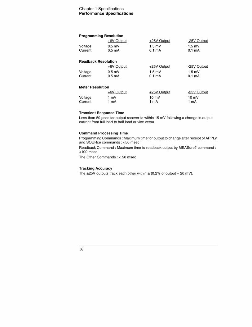
Programming Resolution+6V Output +25V Output -25V Output
Voltage 0.5 mV 1.5 mV 1.5 mVCurrent 0.5 mA 0.1 mA 0.1 mA
Readback Resolution+6V Output +25V Output -25V Output
Voltage 0.5 mV 1.5 mV 1.5 mVCurrent 0.5 mA 0.1 mA 0.1 mA
Meter Resolution+6V Output +25V Output -25V Output
Voltage 1 mV 10 mV 10 mVCurrent 1 mA 1 mA 1 mA
Transient Response TimeLess than 50 μsec for output recover to within 15 mV following a change in output current from full load to half load or vice versa
Command Processing TimeProgramming Commands : Maximum time for output to change after receipt of APPLy and SOURce commands : <50 msec
Readback Command : Maximum time to readback output by MEASure? command : <100 msec
The Other Commands : < 50 msec
Tracking AccuracyThe ±25V outputs track each other within ± (0.2% of output + 20 mV).
16
Chapter 1 Specifications Supplemental Characteristics
1
Supplemental Characteristics
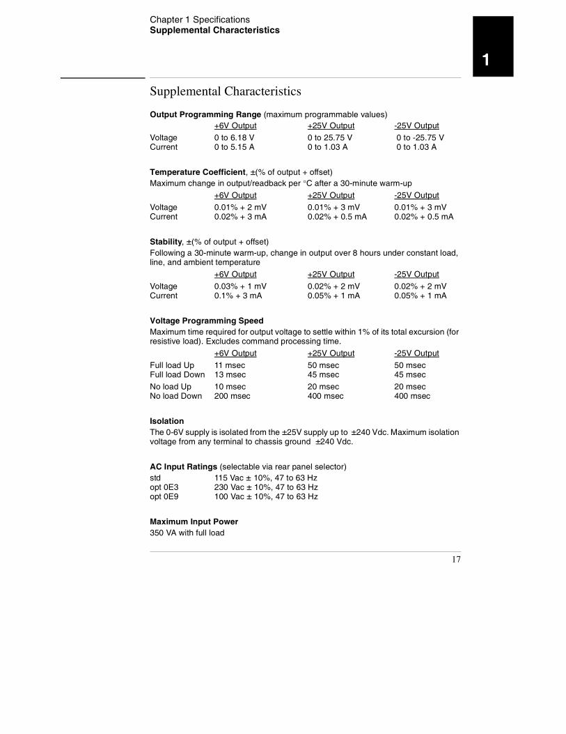
Output Programming Range (maximum programmable values)+6V Output +25V Output -25V Output
Voltage 0 to 6.18 V 0 to 25.75 V 0 to -25.75 VCurrent 0 to 5.15 A 0 to 1.03 A 0 to 1.03 A
Temperature Coefficient, ±(% of output + offset)Maximum change in output/readback per °C after a 30-minute warm-up
+6V Output +25V Output -25V Output
Voltage 0.01% + 2 mV 0.01% + 3 mV 0.01% + 3 mVCurrent 0.02% + 3 mA 0.02% + 0.5 mA 0.02% + 0.5 mA
Stability, ±(% of output + offset)Following a 30-minute warm-up, change in output over 8 hours under constant load, line, and ambient temperature
+6V Output +25V Output -25V Output
Voltage 0.03% + 1 mV 0.02% + 2 mV 0.02% + 2 mVCurrent 0.1% + 3 mA 0.05% + 1 mA 0.05% + 1 mA
Voltage Programming SpeedMaximum time required for output voltage to settle within 1% of its total excursion (for resistive load). Excludes command processing time.
+6V Output +25V Output -25V Output
Full load Up 11 msec 50 msec 50 msecFull load Down 13 msec 45 msec 45 msec
No load Up 10 msec 20 msec 20 msecNo load Down 200 msec 400 msec 400 msec
IsolationThe 0-6V supply is isolated from the ±25V supply up to ±240 Vdc. Maximum isolation voltage from any terminal to chassis ground ±240 Vdc.
AC Input Ratings (selectable via rear panel selector)std 115 Vac ± 10%, 47 to 63 Hzopt 0E3 230 Vac ± 10%, 47 to 63 Hzopt 0E9 100 Vac ± 10%, 47 to 63 Hz
Maximum Input Power350 VA with full load
17
Chapter 1 Specifications Supplemental Characteristics
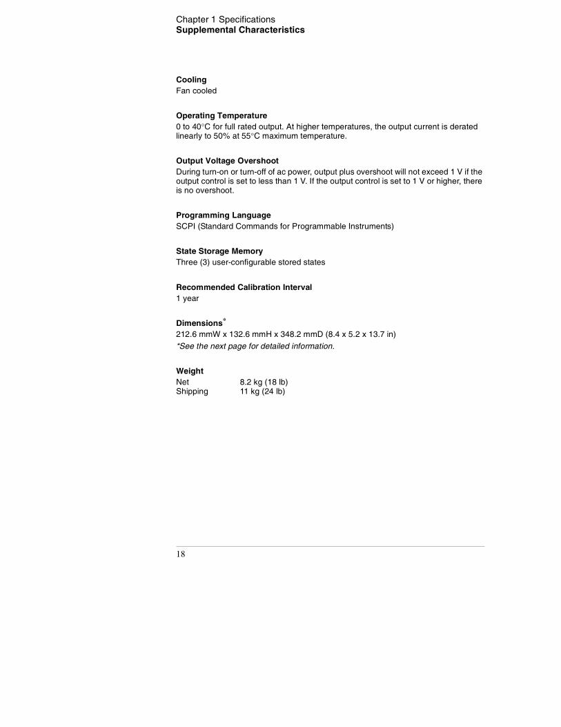
CoolingFan cooled
Operating Temperature0 to 40°C for full rated output. At higher temperatures, the output current is derated linearly to 50% at 55°C maximum temperature.
Output Voltage OvershootDuring turn-on or turn-off of ac power, output plus overshoot will not exceed 1 V if the output control is set to less than 1 V. If the output control is set to 1 V or higher, there is no overshoot.
Programming LanguageSCPI (Standard Commands for Programmable Instruments)
State Storage MemoryThree (3) user-configurable stored states
Recommended Calibration Interval1 year
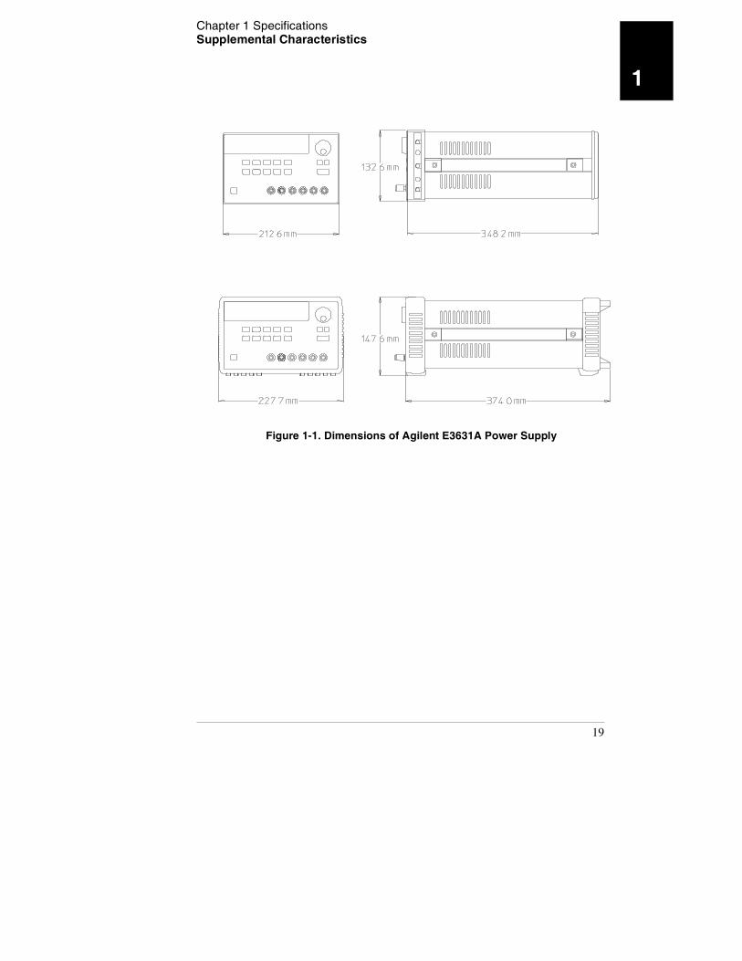
Dimensions*
212.6 mmW x 132.6 mmH x 348.2 mmD (8.4 x 5.2 x 13.7 in)
*See the next page for detailed information.
WeightNet 8.2 kg (18 lb)Shipping 11 kg (24 lb)
18
Chapter 1 Specifications Supplemental Characteristics
1
Figure 1-1. Dimensions of Agilent E3631A Power Supply
19

Chapter 1 Specifications Supplemental Characteristics
20

2
2
Quick Start
Quick Start
One of the first things you will want to do with your power supply is to become
acquainted with its front panel. Written procedures in this chapter prepare the
power supply for use and familiarize you with most front-panel operations.
• The power supply is shipped from the factory configured in the front-panel
operation mode. At power-on, the power supply is automatically set to
operate in the front-panel operation mode. When in this mode, the front-
panel keys can be used. When the power supply is in remote operation mode,
you can return to front-panel operation mode at any time by pressing the
key if you did not previously send the front-panel lockout command.
A change between front-panel and remote operation modes will not result
in a change in the output parameters.
• When you press the key (the Lmt annunciator blinks), the
display of the power supply goes to the limit mode and the present limit
values of the selected supply will be displayed. In this mode, you can also
observe the change of the limit values when adjusting the knob. If you press
the key again or let the display time-out after several
seconds, the power supply will return the display to the meter mode (the
Lmt annunciator turns off). In this mode, the actual output voltage and
current will be displayed.
• All outputs of the power supply can be enabled or disabled from the front
panel using the key. When the output of the power supply
is off, the OFF annunciator turns on and the three outputs are disabled.
• The display provides the present operating status of the power supply with
annunciators and also informs the user of error codes. For example, the +6V
supply is operating in CV mode and controlled from the front panel, then
the CV and +6V annunciators will turn on. If, however, the power supply is
remotely controlled, the Rmt annunciator will also turn on, and when the
power supply is being addressed over GPIB interface, the Adrs annunciator
will turn on. see "Display Annunciators" on page 5 for more information.
Throughout this chapter the key to be pressed is shown in the left margin.
Local
Display Limit
Display Limit
Output On/Off
22
Chapter 2 Quick Start To prepare the power supply for use
2
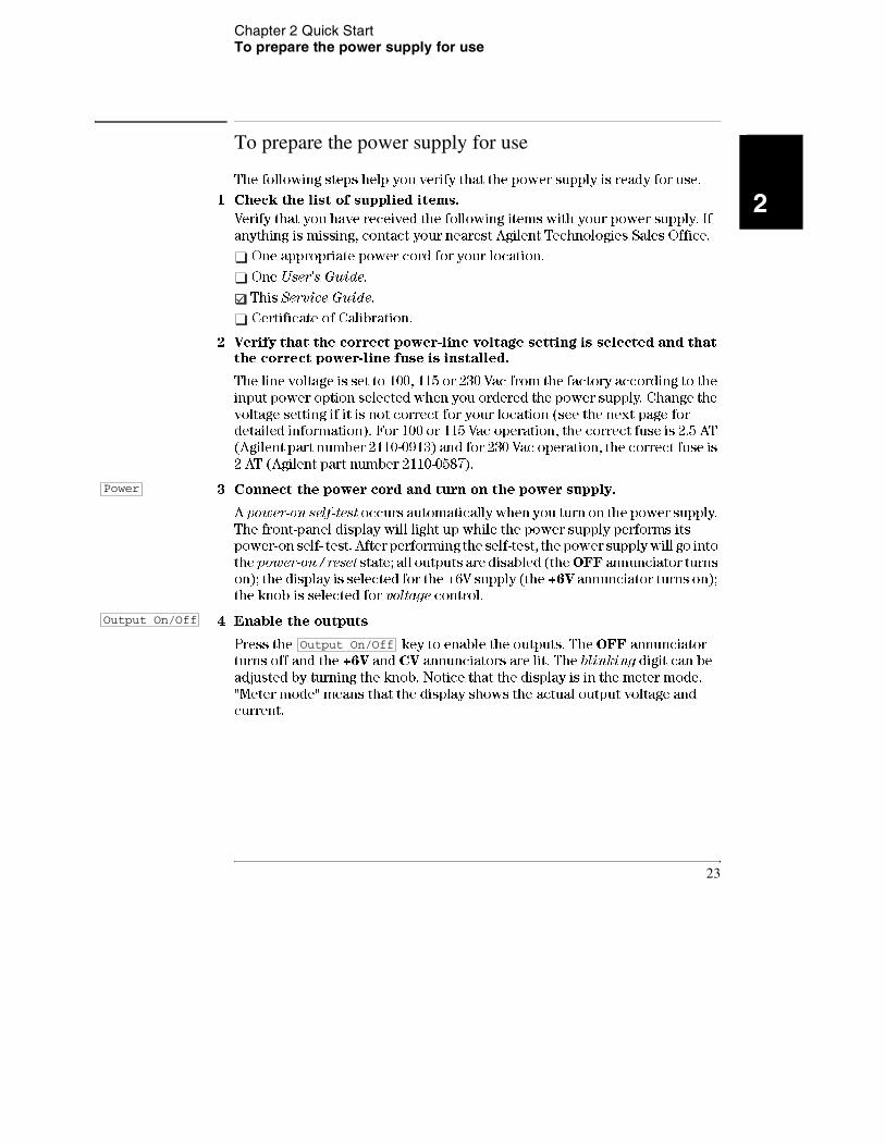
To prepare the power supply for use
The following steps help you verify that the power supply is ready for use.
1 Check the list of supplied items.
Verify that you have received the following items with your power supply. If
anything is missing, contact your nearest Agilent Technologies Sales Office.
One appropriate power cord for your location.
One User's Guide.
This Service Guide.
Certificate of Calibration.
2 Verify that the correct power-line voltage setting is selected and that the correct power-line fuse is installed.
The line voltage is set to 100, 115 or 230 Vac from the factory according to the
input power option selected when you ordered the power supply. Change the
voltage setting if it is not correct for your location (see the next page for
detailed information). For 100 or 115 Vac operation, the correct fuse is 2.5 AT
(Agilent part number 2110-0913) and for 230 Vac operation, the correct fuse is
2 AT (Agilent part number 2110-0587).
3 Connect the power cord and turn on the power supply.
A power-on self-test occurs automatically when you turn on the power supply.
The front-panel display will light up while the power supply performs its
power-on self- test. After performing the self-test, the power supply will go into
the power-on / reset state; all outputs are disabled (the OFF annunciator turns
on); the display is selected for the +6V supply (the +6V annunciator turns on);
the knob is selected for voltage control.
4 Enable the outputs
Press the key to enable the outputs. The OFF annunciator
turns off and the +6V and CV annunciators are lit. The blinking digit can be
adjusted by turning the knob. Notice that the display is in the meter mode.
"Meter mode" means that the display shows the actual output voltage and
current.
Power
Output On/Off
Output On/Off
23
Chapter 2 Quick Start To prepare the power supply for use
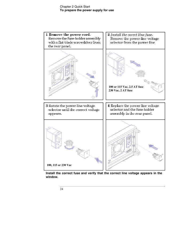
1 Remove the power cord. Remove the fuse-holder assembly with a flat-blade screwdriver from the rear panel.
2 Install the corect line fuse. Remove the power-line voltage selector from the power-line
3 Rotate the power-line voltage selector until the correct voltage appears.
4 Replace the power-line voltage selector and the fuse-holder assembly in the rear panel.
Install the correct fuse and verify that the correct line voltage appears in the window.
100 or 115 Vac, 2.5 AT fuse 230 Vac, 2 AT fuse
100, 115 or 230 Vac
24
Chapter 2 Quick Start To check the rated voltages of the power supply
2
To check the rated voltages of the power supply
The following procedures check to ensure that the power supply develops its
rated voltage outputs with no load and properly responds to operation from
the front panel.
For each step, use the keys shown on the left margins.
1 Turn on the power supply.
The power supply will go into the power-on / reset state; all outputs are disabled
(the OFF annunciator turns on); the display is selected for the +6V supply (the
+6V annunciator turns on); and the knob is selected for voltage control.
2 Enable the outputs.
The OFF annunciator turns off and the +6V and CV annunciators are lit. The
blinking digit can be adjusted by turning the knob. Notice that the display is
in the meter mode. "Meter mode" means that the display shows the actual
output voltage and current.
3 Check that the front-panel voltmeter properly responds to knob control for +6V supply.
Turn the knob clockwise or counter clockwise to check that the voltmeter
responds to knob control and the ammeter indicates nearly zero.
4 Ensure that the voltage can be adjusted from zero to the maximum rated value. 1
Adjust the knob until the voltmeter indicates 0 volts and then adjust the knob
until the voltmeter indicates 6.0 volts.
1You can use the resolution selection keys to move the blinking digit to the right or
left when setting the voltage.
Power
Output On/Off
25
Chapter 2 Quick Start To check the rated voltages of the power supply
5 Check the voltage function for the +25V supply.
Select the meter and adjust selection key for the +25V supply. The CV
annunciator is still lit and the +25V annunciator will turn on. Repeat steps (3)
and (4) to check the voltage function for the +25V supply.
6 Check the voltage function for the -25V supply.
Select the meter and adjust selection key for the -25V supply. The CV
annunciator is still lit and the -25V annunciator will turn on. Repeat steps (3)
and (4) to check the voltage function for the -25V supply.
+25V
-25V
26
Chapter 2 Quick Start To check the rated currents of the power supply
2
To check the rated currents of the power supply
The following procedures check to ensure that the power supply develops its
rated current outputs with a short and properly responds to operation from
the front panel.
For each step, use the keys shown on the left margin.
1 Turn on the power supply.
The power supply will go into the power-on / reset state; all outputs are disabled
(the OFF annunciator turns on); the display is selected for the +6V supply (the
+6V annunciator turns on); and the knob is selected for voltage control.
2 Connect a short across (+) and (-) output terminals of +6V supply with an insulated test lead.
3 Enable the outputs.
The OFF annunciator turns off and the +6V annunciator turns on. The CV or
CC annunciator is lit depending on the resistance of the test lead. The blinking
digit can be adjusted by turning the knob. Notice that the display is in the meter
mode. "Meter mode" means that the display shows the actual output voltage
and current.
4 Adjust the voltage limit value to 1.0 volt.
Set the display to the limit mode (the Lmt annunciator will be blinking).
Adjust the voltage limit to 1.0 volt to assure CC operation. The CC annunciator
will light.
5 Check that the front-panel ammeter properly responds to knob control for the +6V supply.
Set the knob to the current control, and turn the knob clockwise or counter
clockwise when the display is in the meter mode (the Lmt annunciator is off).
Check that the ammeter responds to knob control and the voltmeter indicates
nearly zero (actually, the voltmeter will show the voltage drop caused by the
test lead).
Power
Output On/Off
Display Limit
Vol/Cur
27
Chapter 2 Quick Start To check the rated currents of the power supply
6 Ensure that the current can be adjusted from zero to the maximum rated value. 1
Adjust the knob until the ammeter indicates 0 amps and then until the ammeter
indicates 5.0 amps.
7 Check the current function for the +25V supply.
Disable the outputs by pressing the key and connect a short
across (+) and (COM) output terminals of the ±25V supply with an insulated
test lead. Repeat steps (3) through (6) after selecting the meter and adjust
selection key for the +25V supply.
8 Check the current function for the -25V supply.
Disable the outputs by pressing the key and connect a short
across (-) and (COM) output terminals of the ±25V supply with an insulated
test lead. Repeat steps (3) through (6) after selecting the meter and adjust
selection key for the -25V supply.
N o t e If an error has been detected during the output checkout procedures, the
ERROR annunciator will turn on. See "Error Messages" for more
information, starting on page 113 in chapter 5 of the User's Guide.
1You can use the resolution selection keys to move the blinking digit to the
right or left when setting the current.
+25V
Output On/Off
-25V
Output On/Off
28
Chapter 2 Quick Start To use the power supply in constant voltage mode
2
To use the power supply in constant voltage mode
To set up the power supply for constant voltage (CV) operation, proceed as
follows.
For each step, use the keys shown on the left margin.
1 Connect a load to the desired output terminals.
With power-off, connect a load to the desired output terminals.
2 Turn on the power supply.
The power supply will go into the power-on / reset state; all outputs are disabled
(the OFF annunciator turns on); the display is selected for the +6V supply (the
+6V annunciator turns on); and the knob is selected for voltage control.
3 Enable the outputs.
The OFF annunciator turns off and the +6V and CV annunciators are lit. The
blinking digit can be adjusted by turning the knob. Notice that the display is
in the meter mode. "Meter mode" means that the display shows the actual
output voltage and current.
To set up the power supply for +25V supply or -25V supply operation, you
should press the or key to select the display and adjust for +25V
supply or -25V supply before proceeding to the next step.
4 Set the display for the limit mode.
Notice that the Lmt annunciator blinks, indicating that the display is in the
limit mode. When the display is in the limit mode, you can see the voltage and
current limit values of the selected supply.
In constant voltage mode, the voltage values between meter mode and
limit mode are the same, but the current values are not. Further if the
display is in the meter mode, you cannot see the change of current limit
value when adjusting the knob. We recommend that you should set the
display to "limit" mode to see the change of current limit value in
constant voltage mode whenever adjusting the knob.
Power
Output On/Off
+25V -25V
Display Limit
29
Chapter 2 Quick Start To use the power supply in constant voltage mode
5 Adjust the knob for the desired current limit. 1
Check that the Lmt annunciator still blinks. Set the knob for current control.
The second digit of ammeter will be blinking. Adjust the knob to the desired
current limit.
6 Adjust the knob for the desired output voltage. 1
Set the knob for voltage control. The second digit of the voltmeter will be
blinking. Adjust the knob to the desired output voltage.
7 Return to the meter mode.
key or let the display time-out after several seconds to return
to the meter mode. Notice that the Lmt annunciator turns off and the display
returns to the meter mode. In the meter mode, the display shows the actual
output voltage and current of the selected supply.
8 Verify that the power supply is in the constant voltage mode.
If you operate the +6V supply in the constant voltage (CV) mode, verify that
CV and +6V annunciators are lit. If you operate the power supply for +25V
supply or -25V supply, the +25V or -25V annunciator will turn on. If the CC
annunciator is lit, choose a higher current limit.
N o t e During actual CV operation, if a load change causes the current limit to be
exceeded, the power supply will automatically crossover to constant current
mode at the preset current limit and the output voltage will drop
proportionately.
1You can use the resolution selection keys to move the blinking digit to the right or
left when setting the voltage and current.
Vol/Cur
Vol/Cur
Display Limit
Display Limit
30
Chapter 2 Quick Start To use the power supply in constant current mode
2
To use the power supply in constant current mode
To set up the power supply for constant current (CC) operation, proceed as
follows.
For each step, use the keys shown on the left margin.
1 Connect a load to the output terminals of the desired supply.
With power-off, connect a load to the desired output terminals.
2 Turn on the power supply.
The power supply will go into the power-on / reset state; all outputs are disabled
(the OFF annunciator turns on); the display is selected for the +6V supply (the
+6V annunciator turns on); and the knob is selected for voltage control.
3 Enable the outputs
The OFF annunciator turns off and the +6V and CV annunciators are lit. The
blinking digit can be adjusted by turning the knob. Notice that the display is
in the meter mode. "Meter mode" means that the display shows the actual
output voltage and current.
To set up the power supply for +25V supply or -25V supply operation, you
should press the or key to select the display and adjust for +25V
supply or -25V supply before proceeding to the next step.
4 Set the display for the limit mode.
Notice that the Lmt annunciator blinks, indicating that the display is in the
limit mode. When the display is in the limit mode, you can see the voltage and
current limit values of the selected supply.
In constant current mode, the current values between meter mode and
limit mode are the same, but the voltage values are not. Further if the
display is in the meter mode, you cannot see the change of voltage limit
value when adjusting the knob. We recommend that you should set the
display to "limit" mode to see the change of voltage limit value in
constant current mode whenever adjusting the knob.
Power
Output On/Off
+25V -25V
Display Limit
31
Chapter 2 Quick Start To use the power supply in constant current mode
5 Adjust the knob for the desired voltage limit. 1
Check that the knob is still selected for voltage control and the Lmt
annunciator blinks. Adjust the knob for the desired voltage limit.
6 Adjust the knob for the desired output current. 1
Set the knob for current control. The second digit of the ammeter will be
blinking. Adjust the knob to the desired current output.
7 Return to the meter mode.
Press the key or let the display time-out after several seconds
to return the meter mode. Notice that the Lmt annunciator turns off and the
display returns to the meter mode. In the meter mode, the display shows the
actual output voltage and current of the selected supply.
8 Verify that the power supply is in the constant current mode.
If you operate the +6V supply in the constant current (CC) mode, verify that
CC and +6V annunciators are lit. If you operate the power supply for +25V
supply or -25V supply, the +25V or -25V annunciator will turn on. If the CV
annunciator is lit, choose a higher voltage limit.
N o t e During actual CC operation, if a load change causes the voltage limit to be
exceeded, the power supply will automatically crossover to constant voltage
mode at the preset voltage limit and the output current will drop
proportionately.
1You can use the resolution selection keys to move the blinking digit to the right or
left when setting the voltage and current.
Vol/Cur
Display Limit
Display Limit
32
Chapter 2 Quick Start To use the power supply in track mode
2
To use the power supply in track mode
The ±25V supplies provide 0 to ±25 V tracking outputs. In the track mode, two
voltages of the ±25V supplies track each other to within ±(0.2% of output + 20
mV) for convenience in varying the symmetrical voltages needed by
operational amplifiers and other circuits using balanced positive and negative
inputs.
To operate the power supply in the track mode, proceed as follows:
1 Set the +25V supply to the desired voltage as described in previous section "To use the power supply in constant voltage mode" (see page 29 for detailed information).
2 Enable the track mode.
The key must be depressed for at least 1 second to enable the track
mode. When the track mode is first enabled, the -25V supply will be set to the
same voltage level as the +25V supply. Once enabled, any change of the voltage
level in either the +25V supply or the -25V supply will be reflected in other
supply. The current limit is independently set for each of the +25V or the -25V
supply and is not affected by the track mode.
3 Verify that ±25V supplies track each other properly.
You can verify that the voltage of the -25V supply tracks that of the +25V supply
within ±(0.2% of output + 20 mV) from the front-panel display by comparing
the voltage values of the +25V supply and the -25V supply.
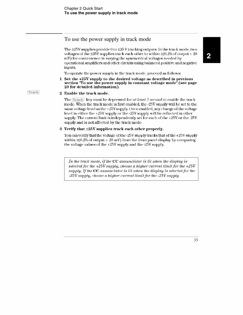
In the track mode, if the CC annunciator is lit when the display is
selected for the +25V supply, choose a higher current limit for the +25V
supply. If the CC annunciator is lit when the display is selected for the -25V supply, choose a higher current limit for the -25V supply.
Track
Track
33
Chapter 2 Quick Start To store and recall the instrument state
To store and recall the instrument state
You can store up to three different operating states in non-volatile memory.
This also enables you to recall the entire instrument state with just a few key
presses from the front panel.
The memory locations are supplied from the factory for front panel operation
with the following states: display and knob selection for +6V output; *RST
values of voltage and current limits for three outputs; output disabled; and
track off state. *RST values for +6V supply are 0 V and 5 A and 0 V and 1 A
for the ±25V supplies.
The following steps show you how to store and recall an operating state.
1 Set up the power supply for the desired operating state.
The storage feature "remembers" the display and knob selection state, the limit
values of voltage and current for three outputs, output on/off state, and track
mode state.
2 Turn on the storage mode.
Three memory locations (numbered 1, 2, and 3) are available to store the
operating states. The operating states are stored in non-volatile memory and
are remembered when being recalled.
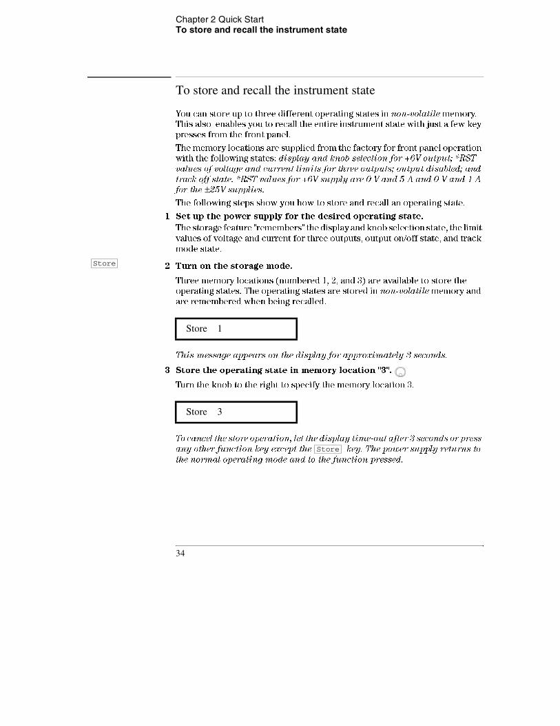
This message appears on the display for approximately 3 seconds.
3 Store the operating state in memory location "3".
Turn the knob to the right to specify the memory location 3.
To cancel the store operation, let the display time-out after 3 seconds or press
any other function key except the key. The power supply returns to
the normal operating mode and to the function pressed.
Store 1
Store 3
Store
Store
34

Chapter 2 Quick Start To store and recall the instrument state
2
4 Save the operating state.
The operating state is now stored. To recall the stored state, go to the following
steps.
This message appears on the display for approximately 1 second.
5 Turn on the recall mode.
Memory location "1" will be displayed in the recall mode.
This message appears on the display for approximately 3 seconds.
6 Recall the stored operating state.
Turn the knob to the right to change the displayed storage location to "3".
If this setting is not followed within 3 seconds with a key stroke, the
power supply returns to normal operating mode and will not recall the
instrument state 3 from memory.
7 Restore the operating state.
The power supply should now be configured in the same state as when you
stored the state on the previous steps.
This message appears on the display for approximately 1 second.
done
recall 1
recall 3
done
Store
Recall
Recall
Recall
35
Chapter 2 Quick Start To rack mount the power supply
To rack mount the power supply
The power supply can be mounted in a standard 19-inch rack cabinet using one
of three optional kits available. A rack-mounting kit for a single instrument is
available as Option 1CM (P/N 5062-3957). Installation instructions and
hardware are included with each rack-mounting kit. Any Agilent Technologies
System II instrument of the same size can be rack-mounted beside the Agilent
E3631A power supply. To rack mount the power supply, follow these
procedures.
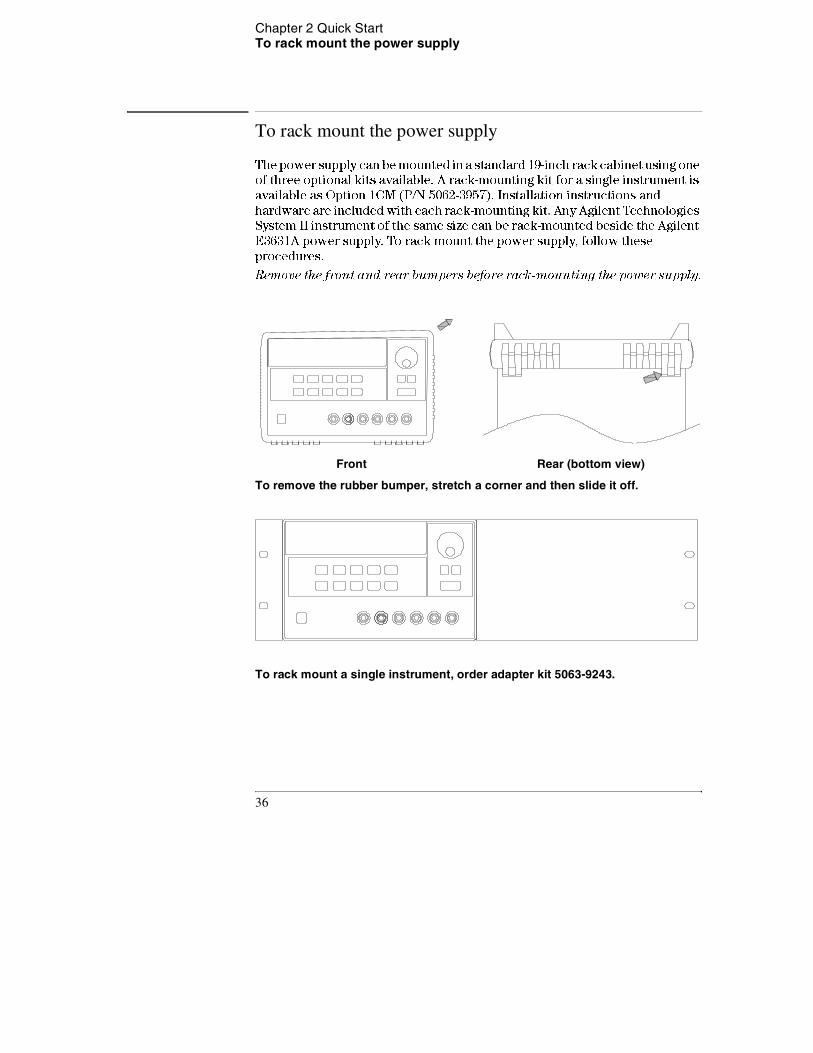
Remove the front and rear bumpers before rack-mounting the power supply.
To remove the rubber bumper, stretch a corner and then slide it off.
To rack mount a single instrument, order adapter kit 5063-9243.
Front Rear (bottom view)
36
Chapter 2 Quick Start To rack mount the power supply
2
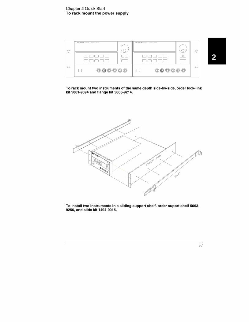
To rack mount two instruments of the same depth side-by-side, order lock-link kit 5061-9694 and flange kit 5063-9214.
To install two instruments in a sliding support shelf, order suport shelf 5063-9256, and slide kit 1494-0015.
37

Chapter 2 Quick Start To rack mount the power supply
38

3
Calibration Procedures

Calibration Procedures
This chapter contains procedures for verification of the power supply's
performance and calibration (adjustment). The chapter is divided into the
following sections:
• Agilent Technologies Calibration Services, page 41
• Calibration Interval, page 41
• Automating Calibration Procedures, page 42
• Recommended Test Equipment, page 42
• Test Considerations, page 43
• Performance Verification Tests, page 44
• Measurement Techniques, page 45
• Constant Voltage (CV) Verifications, page 47
• Constant Current (CC) Verifications, page 54
• Performance Test Record for Agilent E3631A, page 60
• Calibration Security Code, page 62
• Calibration Count, page 66
• Calibration Message, page 66
• General Calibration/Adjustment Procedure, page 67
• Aborting a Calibration in Progress, page 72
• Calibration Record for Agilent E3631A, page 73
• Error Messages, page 74
• Calibration Program, page 76
The performance verification tests for constant voltage (CV) and constant
current (CC) operations use the power supply's specifications listed in chapter
1, Specifications, starting on page 13.
40
Chapter 3 Calibration Procedures Agilent Technologies Calibration Services
3
Closed-Case Electronic Calibration The power supply features closed-
case electronic calibration since no internal mechanical adjustments are
required for normal calibration. The power supply calculates correction
factors based upon the input reference value you enter. The new correction
factors are stored in non-volatile memory until the next calibration adjustment
is performed. (Non-volatile memory does not change when power has been off
or after a remote interface reset.)
Agilent Technologies Calibration Services
When your power supply is due for calibration, contact your local Agilent
Technologies Service Center for a low-cost calibration. The Agilent E3631A
power supply is supported on calibration processes which allow Agilent
Technologies to provide this service at competitive prices.
Calibration Interval
The power supply should be calibrated on a regular interval determined by the
accuracy requirements of your application. A 1-year interval is adequate for
most applications. Agilent Technologies does not recommend extending
calibration intervals beyond 1 year for any application. Agilent Technologies
recommends that complete re-adjustment should always be performed at the
calibration interval. This will increase your confidence that the Agilent E3631A
will remain within specification for the next calibration interval. This criteria
for re-adjustment provides the best long-term stability.
41
Chapter 3 Calibration Procedures Automating Calibration Procedures
Automating Calibration Procedures
You can automate the complete verification procedures outlined in this chapter if you have access to programmable test equipment. You can program the instrument configurations specified for each test over the remote interface. You can then enter readback verification data into a test program and compare the results to the appropriate test limit values.
You can also enter calibration constants from the remote interface. Remote operation is similar to the local front-panel procedure. You can use a computer to perform the adjustment by first selecting the required setup. The calibration value is sent to the power supply and then the calibration is initiated over the remote interface. The power supply must be unsecured prior to initiating the calibration procedure. An Agilent BASIC program for calibration over the GPIB interface is listed at the end of this chapter.
For further details on programming the power supply, see chapters 3 and 4 in the Agilent E3631A User's Guide.
Recommended Test Equipment
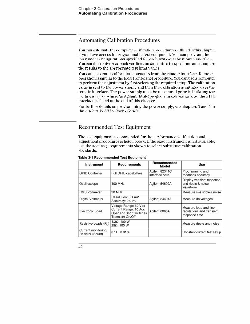
The test equipment recommended for the performance verification and adjustment procedures is listed below. If the exact instrument is not available, use the accuracy requirements shown to select substitute calibration standards.
Table 3-1 Recommended Test Equipment
Instrument Requirements Recommended Model Use
GPIB Controller Full GPIB capabilities Agilent 82341C interface card
Programming and readback accuracy
Oscilloscope 100 MHz Agilent 54602ADisplay transient response and ripple & noise waveform
RMS Voltmeter 20 MHz Measure rms ripple & noise
Digital Voltmeter Resolution: 0.1 mV Accuracy: 0.01% Agilent 34401A Measure dc voltages
Electronic Load
Voltage Range: 50 Vdc Current Range: 10 Adc Open and Short Switches Transient On/Off
Agilent 6063AMeasure load and line regulations and transient response time.
Resistive Loads (RL) 1.2Ω, 100 W 25Ω, 100 W Measure ripple and noise
Current monitoring Resistor (Shunt) 0.1Ω, 0.01% Constant current test setup
42
Chapter 3 Calibration Procedures Test Considerations
3
Test Considerations
To ensure proper instrument operation, verify that you have selected the
correct power-line voltage prior to attempting any test procedure in this
chapter. See page 24 in chapter 2 for more information.
• Assure that the calibration ambient temperature is stable and between 20°C
and 30°C.
• Assure ambient relative humidity is less than 80%.
• Allow a 1-hour warm-up period before verification or calibration.
• Keep cables as short as possible, consistent with the impedance
requirements.
C a u t i o n The tests should be performed by qualified personnel. During performance verification tests, hazardous voltages may be present at the outputs of the power supply.
43
Chapter 3 Calibration Procedures Performance Verification Tests
Performance Verification Tests
The performance verification tests use the power supply's specifications listed
in chapter 1, "Specifications", starting on page 13.
You can perform two different levels of performance verification tests:
• Self-Test A series of internal verification tests that provide high
confidence that the power supply is operational.
• Performance Verification Tests These tests can be used to verify the
power supply's specifications following repairs to specific circuits. The
performance test procedures must be performed on each output.
Self-Test
A power-on self-test occurs automatically when you turn on the power supply.
This limited test assures you that the power supply is operational.
The complete self-test is enabled by pressing the key (actually any
front panel keys except the key) and the power-line switch
simultaneously and then continuing to press the key for 5 seconds.
The complete self-test will be finished in 2 more seconds.
You can also perform a self-test from the remote interface (see chapter 3 in
the Agilent E3631A User's Guide).
• If the self-test is successful, "PASS" is displayed on the front panel.
• If the self-test fails, "FAIL" is displayed and the ERROR annunciator turns
on. If repair is required, see chapter 5, "Service", starting on page 91, for
further details.
• If self-test passes, you have a high confidence that the power supply is
operational.
Performance Verification Tests
These tests can be used to verify the power supply's specifications following
repairs to specific circuits. The following sections explain all verification
procedures in detail. All of the performance test specifications are shown in
each test.
Recall
Error
Recall
44
Chapter 3 Calibration Procedures Measurement Techniques
3
Measurement Techniques
Setup for Most Tests
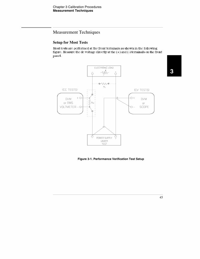
Most tests are performed at the front terminals as shown in the following
figure. Measure the dc voltage directly at the (+) and (-) terminals on the front
panel.
Figure 3-1. Performance Verification Test Setup
45
Chapter 3 Calibration Procedures Measurement Techniques
Electronic Load
Many of the test procedures require the use of a variable load resistor capable
of dissipating the required power. Using a variable load resistor requires that
switches be used to connect, disconnect, and short the load resistor. An
electronic load, if available, can be used in place of a variable load resistor and
switches. The electronic load is considerably easier to use than load resistors.
It eliminates the need for connecting resistors or rheostats in parallel to handle
power, it is much more stable than carbon-pile load, and it makes easy work
of switching between load conditions as is required for the load regulation and
load transient response tests. Substitution of the electronic load requires minor
changes to the test procedures in this chapter.
Current-Monitoring ResistorTo eliminate output current measurement error caused by the voltage drops
in the leads and connections, connect the current monitoring resistor between
the (-) output terminal and the load as a four-terminal device. Connect the
current-monitoring leads inside the load-lead connections directly at the
monitoring points on the resistor element (see RM in Figure 3-1).
Programming
Most performance tests can be performed only from the front panel. However,
a GPIB or RS-232 controller is required to perform the voltage and current
programming accuracy and readback accuracy tests.
The test procedures are written assuming that you know how to program the
power supply either from the front panel or from an GPIB or RS-232 controller.
Complete instructions on front panel and remote programming are given in the
Agilent E3631A User's Guide.
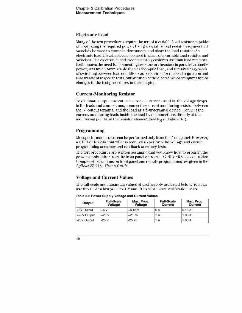
Voltage and Current ValuesThe full-scale and maximum values of each supply are listed below. You can
use this table when you test CV and CC performance verification tests.
Table 3-2 Power Supply Voltage and Current Values
Output Full-Scale Voltage
Max. Prog. Voltage
Full-Scale Current
Max. Prog. Current
+6V Output +6 V +6.18 V 5 A 5.15 A
+25V Output +25 V +25.75 1 A 1.03 A
-25V Output -25 V -25.75 1 A 1.03 A
46
Chapter 3 Calibration Procedures Constant Voltage (CV) Verifications
3
Constant Voltage (CV) Verifications
Constant Voltage Test Setup
If more than one meter or a meter and an oscilloscope are used, connect each
to the (+) and (-) terminals by a separate pair of leads to avoid mutual coupling
effects. Use coaxial cable or shielded 2-wire cable to avoid noise pick-up on
the test leads.
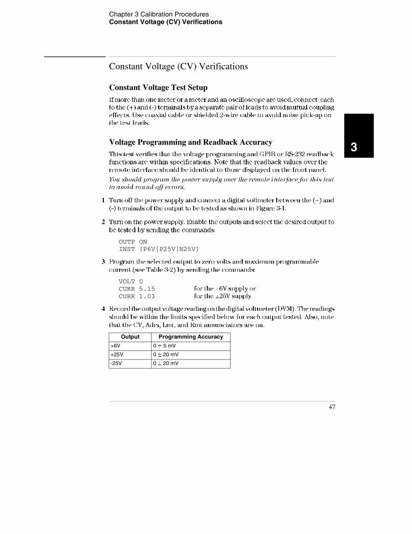
Voltage Programming and Readback AccuracyThis test verifies that the voltage programming and GPIB or RS-232 readback
functions are within specifications. Note that the readback values over the
remote interface should be identical to those displayed on the front panel.
You should program the power supply over the remote interface for this test
to avoid round off errors.
1 Turn off the power supply and connect a digital voltmeter between the (+) and
(-) terminals of the output to be tested as shown in Figure 3-1.
2 Turn on the power supply. Enable the outputs and select the desired output to
be tested by sending the commands:
OUTP ON INST {P6V|P25V|N25V}
3 Program the selected output to zero volts and maximum programmable
current (see Table 3-2) by sending the commands:
VOLT 0 CURR 5.15 for the +6V supply or CURR 1.03 for the ±25V supply
4 Record the output voltage reading on the digital voltmeter (DVM). The readings
should be within the limits specified below for each output tested. Also, note
that the CV, Adrs, Lmt, and Rmt annunciators are on.
Output Programming Accuracy
+6V 0 ± 5 mV
+25V 0 ± 20 mV
-25V 0 ± 20 mV
47
Chapter 3 Calibration Procedures Constant Voltage (CV) Verifications
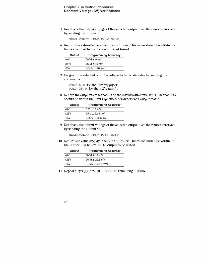
5 Readback the output voltage of the selected output over the remote interface
by sending the command:
MEAS:VOLT? {P6V|P25V|N25V}
6 Record the value displayed on the controller. This value should be within the
limits specified below for each output tested.
7 Program the selected output's voltage to full scale value by sending the
commands.
VOLT 6.0 for the +6V supply or VOLT 25.0 for the ± 25V supply
8 Record the output voltage reading on the digital voltmeter (DVM). The readings
should be within the limits specified below for each output tested.
9 Readback the output voltage of the selected output over the remote interface
by sending the command:
MEAS:VOLT? {P6V|P25V|N25V}
10 Record the value displayed on the controller. This value should be within the
limits specified below for the output to be tested.
11 Repeat steps (1) through (10) for the remaining outputs.
Output Programming Accuracy
+6V DVM ± 5 mV
+25V DVM ± 10 mV
-25V -(DVM ± 10 mV)
Output Programming Accuracy
+6V 6 V ± 11 mV
+25V 25 V ± 32.5 mV
-25V -(25 V ± 32.5 mV)
Output Programming Accuracy
+6V DVM ± 11 mV
+25V DVM ± 22.5 mV
-25V -(DVM ± 22.5 mV)
48
Chapter 3 Calibration Procedures Constant Voltage (CV) Verifications
3
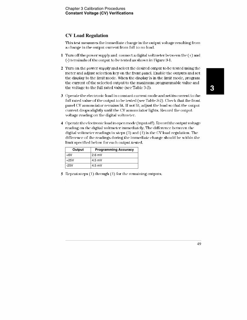
CV Load Regulation
This test measures the immediate change in the output voltage resulting from
a change in the output current from full to no load.
1 Turn off the power supply and connect a digital voltmeter between the (+) and
(-) terminals of the output to be tested as shown in Figure 3-1.
2 Turn on the power supply and select the desired output to be tested using the
meter and adjust selection key on the front panel. Enable the outputs and set
the display to the limit mode. When the display is in the limit mode, program
the current of the selected output to the maximum programmable value and
the voltage to the full rated value (see Table 3-2).
3 Operate the electronic load in constant current mode and set its current to the
full rated value of the output to be tested (see Table 3-2). Check that the front
panel CV annunciator remains lit. If not lit, adjust the load so that the output
current drops slightly until the CV annunciator lights. Record the output
voltage reading on the digital voltmeter.
4 Operate the electronic load in open mode (input off). Record the output voltage
reading on the digital voltmeter immediately. The difference between the
digital voltmeter readings in steps (3) and (4) is the CV load regulation. The
difference of the readings during the immediate change should be within the
limit specified below for each output tested.
5 Repeat steps (1) through (4) for the remaining outputs.
Output Programming Accuracy
+6V 2.6 mV
+25V 4.5 mV
-25V 4.5 mV
49
Chapter 3 Calibration Procedures Constant Voltage (CV) Verifications
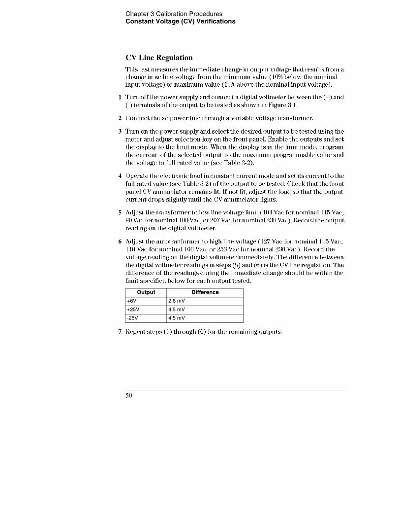
CV Line Regulation
This test measures the immediate change in output voltage that results from a
change in ac line voltage from the minimum value (10% below the nominal
input voltage) to maximum value (10% above the nominal input voltage).
1 Turn off the power supply and connect a digital voltmeter between the (+) and
(-) terminals of the output to be tested as shown in Figure 3-1.
2 Connect the ac power line through a variable voltage transformer.
3 Turn on the power supply and select the desired output to be tested using the
meter and adjust selection key on the front panel. Enable the outputs and set
the display to the limit mode. When the display is in the limit mode, program
the current of the selected output to the maximum programmable value and
the voltage to full rated value (see Table 3-2).
4 Operate the electronic load in constant current mode and set its current to the
full rated value (see Table 3-2) of the output to be tested. Check that the front
panel CV annunciator remains lit. If not lit, adjust the load so that the output
current drops slightly until the CV annunciator lights.
5 Adjust the transformer to low line voltage limit (104 Vac for nominal 115 Vac,
90 Vac for nominal 100 Vac, or 207 Vac for nominal 230 Vac). Record the output
reading on the digital voltmeter.
6 Adjust the autotranformer to high line voltage (127 Vac for nominal 115 Vac,
110 Vac for nominal 100 Vac, or 253 Vac for nominal 230 Vac). Record the
voltage reading on the digital voltmeter immediately. The difference between
the digital voltmeter readings in steps (5) and (6) is the CV line regulation. The
difference of the readings during the immediate change should be within the
limit specified below for each output tested.
7 Repeat steps (1) through (6) for the remaining outputs.
Output Difference
+6V 2.6 mV
+25V 4.5 mV
-25V 4.5 mV
50
Chapter 3 Calibration Procedures Constant Voltage (CV) Verifications
3
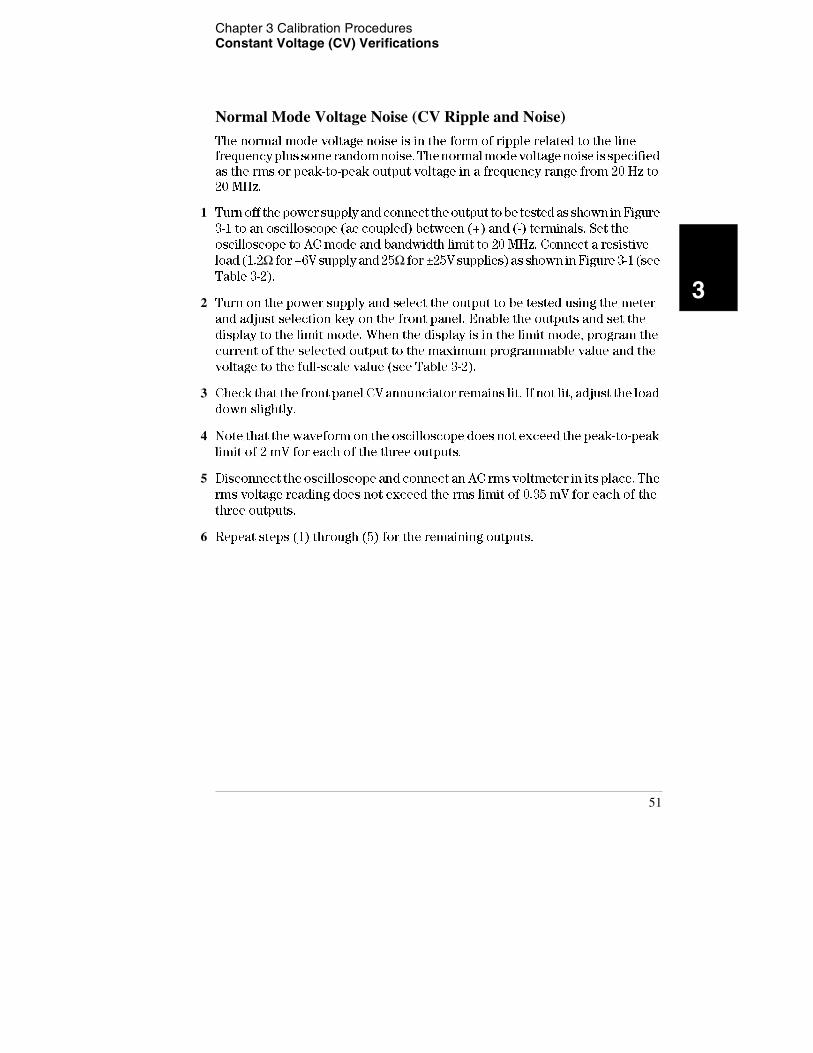
Normal Mode Voltage Noise (CV Ripple and Noise)
The normal mode voltage noise is in the form of ripple related to the line
frequency plus some random noise. The normal mode voltage noise is specified
as the rms or peak-to-peak output voltage in a frequency range from 20 Hz to
20 MHz.
1 Turn off the power supply and connect the output to be tested as shown in Figure
3-1 to an oscilloscope (ac coupled) between (+) and (-) terminals. Set the
oscilloscope to AC mode and bandwidth limit to 20 MHz. Connect a resistive
load (1.2Ω for +6V supply and 25Ω for ±25V supplies) as shown in Figure 3-1 (see
Table 3-2).
2 Turn on the power supply and select the output to be tested using the meter
and adjust selection key on the front panel. Enable the outputs and set the
display to the limit mode. When the display is in the limit mode, program the
current of the selected output to the maximum programmable value and the
voltage to the full-scale value (see Table 3-2).
3 Check that the front panel CV annunciator remains lit. If not lit, adjust the load
down slightly.
4 Note that the waveform on the oscilloscope does not exceed the peak-to-peak
limit of 2 mV for each of the three outputs.
5 Disconnect the oscilloscope and connect an AC rms voltmeter in its place. The
rms voltage reading does not exceed the rms limit of 0.35 mV for each of the
three outputs.
6 Repeat steps (1) through (5) for the remaining outputs.
51

Chapter 3 Calibration Procedures Constant Voltage (CV) Verifications
Common Mode Current Noise
The common mode current is that ac current component which exists between
any or all outputs or output lines and chassis ground. Common mode noise can
be a problem for very sensitive circuitry that is referenced to earth ground.
When a circuit is referenced to earth ground, a low level line-related ac current
will flow from the output terminals to earth ground. Any impedance to earth
ground will create a voltage drop equal to the output current flow multiplied
by the impedance.
1 Turn off the power supply and connect a 100 kΩ resistor (RS) and a 2200 pF
capacitor in parallel between the (-) terminal and chassis ground for +6V output
or between the (COM) terminal and chassis ground for ±25V outputs.
2 Connect a digital voltmeter across RS.
3 Turn on the power supply and select the output to be tested using the meter
and adjust selection key on the front panel. Enable the outputs and set the
display to the limit mode. When the display is in the limit mode, program the
current of the selected output to the maximum programmable value and the
voltage to the full-scale value (see Table 3-2).
4 Record the voltage across RS and convert it to current by dividing by the
resistance (DVM reading/100 kΩ). Note that the current is less than 1.5 μA for
each of the three outputs.
5 Repeat steps (1) through (4) for the remaining outputs.
52
Chapter 3 Calibration Procedures Constant Voltage (CV) Verifications
3
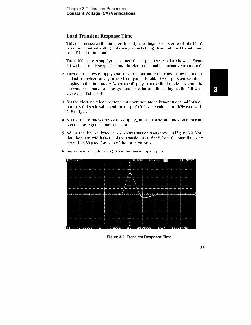
Load Transient Response Time
This test measures the time for the output voltage to recover to within 15 mV
of nominal output voltage following a load change from full load to half load,
or half load to full load.
1 Turn off the power supply and connect the output to be tested as shown in Figure
3-1 with an oscilloscope. Operate the electronic load in constant current mode.
2 Turn on the power supply and select the output to be tested using the meter
and adjust selection key on the front panel. Enable the outputs and set the
display to the limit mode. When the display is in the limit mode, program the
current to the maximum programmable value and the voltage to the full-scale
value (see Table 3-2).
3 Set the electronic load to transient operation mode between one half of the
output's full scale value and the output's full scale value at a 1 kHz rate with
50% duty cycle.
4 Set the the oscilloscope for ac coupling, internal sync, and lock on either the
positive or negative load transient.
5 Adjust the the oscilloscope to display transients as shown in Figure 3-2. Note
that the pulse width (t2-t1) of the transients at 15 mV from the base line is no
more than 50 μsec for each of the three outputs.
6 Repeat steps (1) through (5) for the remaining outputs.
Figure 3-2. Transient Response Time
53
Chapter 3 Calibration Procedures Constant Current (CC) Verifications
Constant Current (CC) Verifications
Constant Current Test Setup
Follow the general setup instructions in the "Measurement Techniques" section
starting on page 45 and the specific instructions will be given in the following
paragraphs.
Current Programming and Readback Accuracy
This test verifies that the current programming and GPIB or RS-232 readback
functions are within specifications. Note that the readback values over the
remote interface should be identical to those displayed on the front panel. The
accuracy of the current monitoring resistor must be 0.1% or better.
You should program the power supply over the remote interface for this test
to avoid round off errors.
1 Turn off the power supply and connect a 0.1Ω current monitoring resistor (RM)
across the output to be tested and a digital voltmeter across the current
monitoring resistor (RM).
2 Turn on the power supply. Enable the outputs and select the desired output to
be tested by sending the commands:
OUTP ON INST {P6V|P25V|N25V}
3 Program the selected output voltage to 5.0 volts and the current to 0 amps by
sending the commands:
VOLT 5 CURR 0
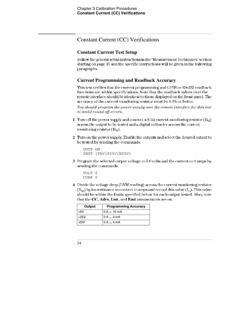
4 Divide the voltage drop (DVM reading) across the current monitoring resistor
(RM) by its resistance to convert to amps and record this value (IO). This value
should be within the limits specified below for each output tested. Also, note
that the CC, Adrs, Lmt, and Rmt annunciators are on.
Output Programming Accuracy
+6V 0 A ± 10 mA
+25V 0 A ± 4 mA
-25V 0 A ± 4 mA
54
Chapter 3 Calibration Procedures Constant Current (CC) Verifications
3
5 Readback the output current from the selected output over the remote
interface by sending the command:
MEAS:CURR? {P6V|P25V|N25V}
6 Record the value displayed on the controller. This value should be within the
limits specified below for each output tested.
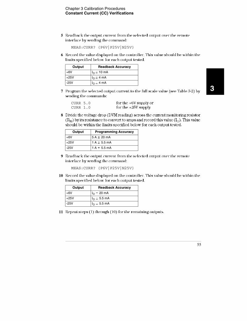
7 Program the selected output current to the full scale value (see Table 3-2) by
sending the commands:
CURR 5.0 for the +6V supply or CURR 1.0 for the ±25V supply
8 Divide the voltage drop (DVM reading) across the current monitoring resistor
(RM) by its resistance to convert to amps and record this value (IO). This value
should be within the limits specified below for each output tested.
9 Readback the output current from the selected output over the remote
interface by sending the command:
MEAS:CURR? {P6V|P25V|N25V}
10 Record the value displayed on the controller. This value should be within the
limits specified below for each output tested.
11 Repeat steps (1) through (10) for the remaining outputs.
Output Readback Accuracy
+6V IO ± 10 mA
+25V IO ± 4 mA
-25V IO ± 4 mA
Output Programming Accuracy
+6V 5 A ± 20 mA
+25V 1 A ± 5.5 mA
-25V 1 A ± 5.5 mA
Output Readback Accuracy
+6V IO ± 20 mA
+25V IO ± 5.5 mA
-25V IO ± 5.5 mA
55
Chapter 3 Calibration Procedures Constant Current (CC) Verifications
CC Load Regulation
This test measures the immediate change in output current resulting from a
change in the load from full rated output voltage to short circuit.
1 Turn off the power supply and connect the output to tested as shown in Figure
3-1 with the digital voltmeter connected across the 0.1Ω current monitoring
resistor (RM).
2 Turn on the power supply and select the desired output to be tested using the
meter and adjust selection key on the front panel. Enable the outputs and set
the display to the limit mode. When the display is in the limit mode, program
the voltage to the maximum programmable value and the current to the full
rated value (see Table 3-2).
3 Operate the electronic load in constant voltage mode and set its voltage to the
full rated value of the output to be tested (see Table 3-2). Check that the CC
annunciator is on. If it is not, adjust the load so that the output voltage drops
slightly. Record the current reading by dividing the voltage reading on the
digital voltmeter by the resistance of the current monitoring resistor.
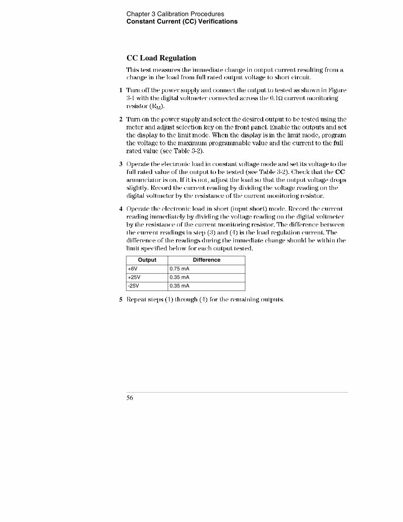
4 Operate the electronic load in short (input short) mode. Record the current
reading immediately by dividing the voltage reading on the digital voltmeter
by the resistance of the current monitoring resistor. The difference between
the current readings in step (3) and (4) is the load regulation current. The
difference of the readings during the immediate change should be within the
limit specified below for each output tested.
5 Repeat steps (1) through (4) for the remaining outputs.
Output Difference
+6V 0.75 mA
+25V 0.35 mA
-25V 0.35 mA
56
Chapter 3 Calibration Procedures Constant Current (CC) Verifications
3
CC Line Regulation
This test measures the immediate change in output current that results from
a change in ac line voltage from the minimum value (10% below the nominal
input voltage) to the maximum value (10% above nominal voltage).
1 Turn off the power supply and connect the output to be tested as shown in Figure
3-1 with the digital voltmeter connected across the current monitoring resistor
(RM).
2 Connect the ac power line through a variable voltage transformer.
3 Turn on the power supply and select the desired output to be tested using the
meter and adjust selection key on the front panel. Enable the outputs and set
the display to the limit mode. When the display is in the limit mode, program
the voltage to the maximum programmable value and the current to the full
rated value (see Table 3-2).
4 Operate the electronic load in constant voltage mode and set its voltage to the
full rated value of the output to be tested (see Table 3-2). Check that the CC
annunciator remains lit. If not lit, adjust the load so that the output voltage
drops slightly until the CC annunciator lights.
5 Adjust the transformer to low line voltage limit (104 Vac for nominal 115 Vac,
90 Vac for nominal 100 Vac, or 207 Vac for nominal 230 Vac). Record the output
current reading by dividing the voltage reading on the digital voltmeter by the
resistance of the current monitoring resistor.
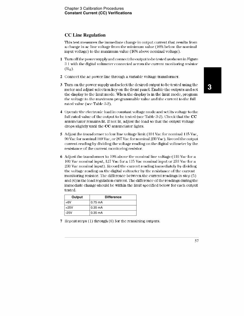
6 Adjust the transformer to 10% above the nominal line voltage (110 Vac for a
100 Vac nominal input, 127 Vac for a 115 Vac nominal input or 253 Vac for a
230 Vac nominal input). Record the current reading immediately by dividing
the voltage reading on the digital voltmeter by the resistance of the current
monitoring resistor. The difference between the current readings in step (5)
and (6) is the load regulation current. The difference of the readings during the
immediate change should be within the limit specified below for each output
tested.
7 Repeat steps (1) through (6) for the remaining outputs.
Output Difference
+6V 0.75 mA
+25V 0.35 mA
-25V 0.35 mA
57

Chapter 3 Calibration Procedures Constant Current (CC) Verifications
58
Chapter 3 Calibration Procedures Constant Current (CC) Verifications
3
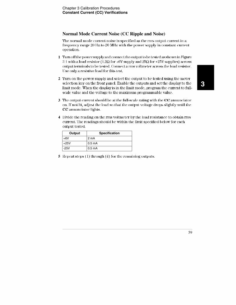
Normal Mode Current Noise (CC Ripple and Noise)
The normal mode current noise is specified as the rms output current in a
frequency range 20 Hz to 20 MHz with the power supply in constant current
operation.
1 Turn off the power supply and connect the output to be tested as shown in Figure
3-1 with a load resistor (1.2Ω for +6V supply and 25Ω for ±25V supplies) across
output terminals to be tested. Connect a rms voltmeter across the load resistor.
Use only a resistive load for this test.
2 Turn on the power supply and select the output to be tested using the meter
selection key on the front panel. Enable the outputs and set the display to the
limit mode. When the display is in the limit mode, program the current to full-
scale value and the voltage to the maximum programmable value.
3 The output current should be at the full-scale rating with the CC annunciator
on. If not lit, adjust the load so that the output voltage drops slightly until the
CC annunciator lights.
4 Divide the reading on the rms voltmeter by the load resistance to obtain rms
current. The readings should be within the limit specified below for each
output tested.
5 Repeat steps (1) through (4) for the remaining outputs.
Output Specification
+6V 2 mA
+25V 0.5 mA
-25V 0.5 mA
59
Chapter 3 Calibration Procedures Performance Test Record for Agilent E3631A
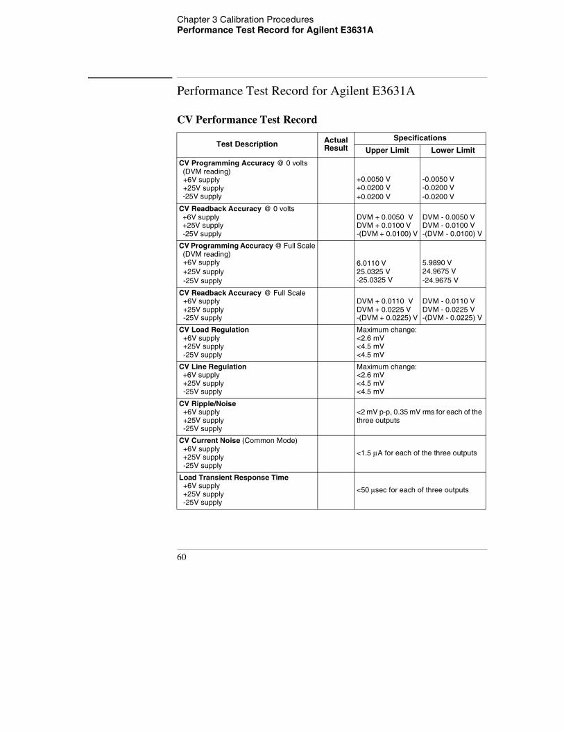
Performance Test Record for Agilent E3631A
CV Performance Test Record
Test Description Actual Result
Specifications
Upper Limit Lower Limit
CV Programming Accuracy @ 0 volts (DVM reading) +6V supply +25V supply -25V supply
+0.0050 V +0.0200 V+0.0200 V
-0.0050 V -0.0200 V-0.0200 V
CV Readback Accuracy @ 0 volts +6V supply +25V supply -25V supply
DVM + 0.0050 V DVM + 0.0100 V -(DVM + 0.0100) V
DVM - 0.0050 V DVM - 0.0100 V -(DVM - 0.0100) V
CV Programming Accuracy @ Full Scale (DVM reading) +6V supply +25V supply -25V supply
6.0110 V 25.0325 V -25.0325 V
5.9890 V 24.9675 V-24.9675 V
CV Readback Accuracy @ Full Scale +6V supply +25V supply -25V supply
DVM + 0.0110 V DVM + 0.0225 V -(DVM + 0.0225) V
DVM - 0.0110 V DVM - 0.0225 V -(DVM - 0.0225) V
CV Load Regulation +6V supply +25V supply -25V supply
Maximum change: <2.6 mV <4.5 mV <4.5 mV
CV Line Regulation +6V supply +25V supply -25V supply
Maximum change: <2.6 mV <4.5 mV <4.5 mV
CV Ripple/Noise +6V supply +25V supply -25V supply
<2 mV p-p, 0.35 mV rms for each of the three outputs
CV Current Noise (Common Mode) +6V supply +25V supply -25V supply
<1.5 μA for each of the three outputs
Load Transient Response Time +6V supply +25V supply -25V supply
<50 μsec for each of three outputs
60
Chapter 3 Calibration Procedures Performance Test Record for Agilent E3631A
3
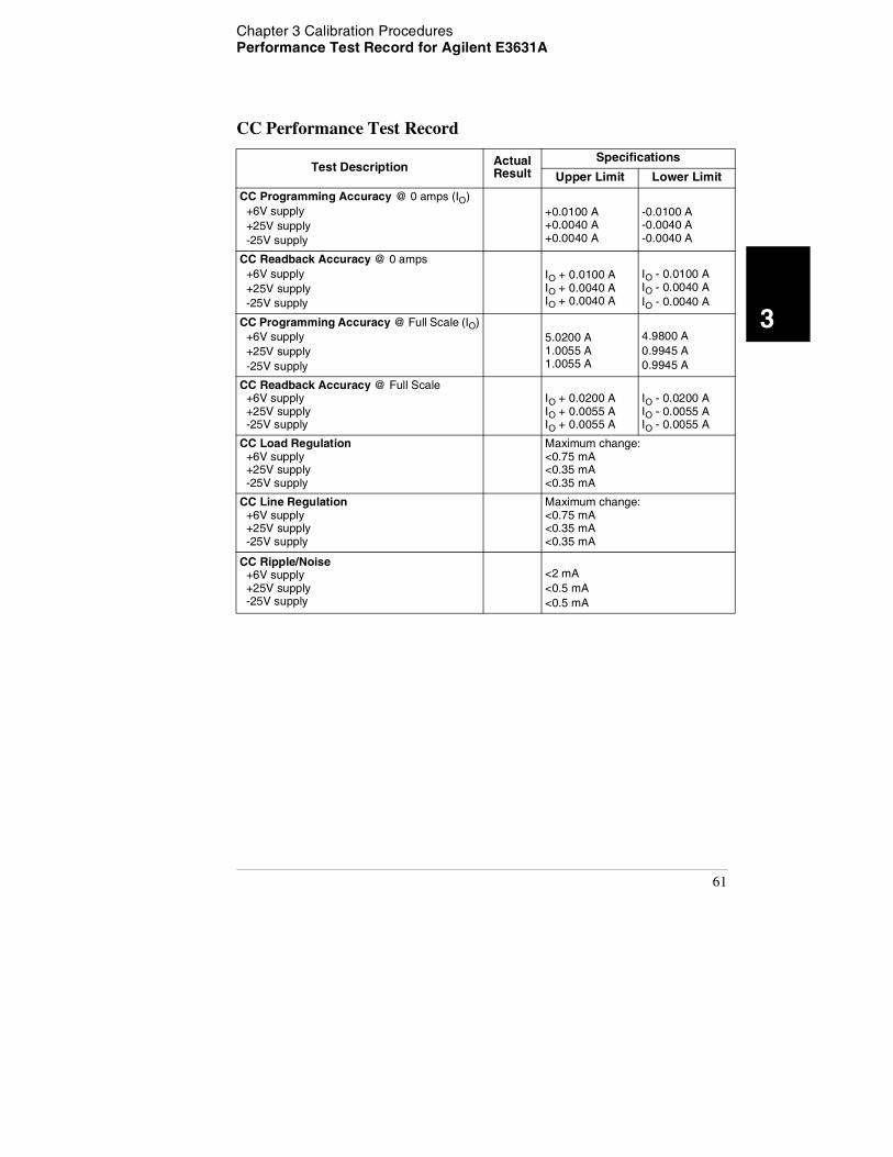
CC Performance Test Record
Test Description Actual Result
Specifications
Upper Limit Lower Limit
CC Programming Accuracy @ 0 amps (IO) +6V supply +25V supply -25V supply
+0.0100 A +0.0040 A +0.0040 A
-0.0100 A -0.0040 A -0.0040 A
CC Readback Accuracy @ 0 amps +6V supply +25V supply -25V supply
IO + 0.0100 A IO + 0.0040 A IO + 0.0040 A
IO - 0.0100 A IO - 0.0040 AIO - 0.0040 A
CC Programming Accuracy @ Full Scale (IO) +6V supply +25V supply -25V supply
5.0200 A 1.0055 A 1.0055 A
4.9800 A0.9945 A0.9945 A
CC Readback Accuracy @ Full Scale +6V supply +25V supply -25V supply
IO + 0.0200 A IO + 0.0055 A IO + 0.0055 A
IO - 0.0200 A IO - 0.0055 A IO - 0.0055 A
CC Load Regulation +6V supply +25V supply -25V supply
Maximum change: <0.75 mA <0.35 mA <0.35 mA
CC Line Regulation +6V supply +25V supply -25V supply
Maximum change: <0.75 mA <0.35 mA <0.35 mA
CC Ripple/Noise +6V supply +25V supply -25V supply
<2 mA<0.5 mA<0.5 mA
61
Chapter 3 Calibration Procedures Calibration Security Code
Calibration Security Code
This feature allows you to enter a security code (electronic key) to prevent
accidental or unauthorized calibrations of the power supply. When you first
receive your power supply, it is secured. Before you can calibrate the power
supply, you must unsecure it by entering the correct security code. A
procedure to unsecure the power supply is given on the following page.
• The security code is set to "HP003631" when the power supply is shipped
from the factory. The security code is stored in non-volatile memory, and
does not change when power has been off or after a remote interface reset.
• To secure the power supply from the remote interface, the security code
may contain up to 12 alphanumeric characters as shown below. The first
character must be a letter, but the remaining characters can be letters or
numbers. You do not have to use all 12 characters but the first character
must always be a letter. A _ _ _ _ _ _ _ _ _ _ _ (12 characters)
• To secure the power supply from the remote interface so that it can be
unsecured from the front panel, use the eight-character format shown
below. The first two characters must be "H P" and the remaining characters
must be numbers. Only the last six characters are recognized from the front
panel, but all eight characters are required. To unsecure the power supply
from the front panel, omit the "H P" and enter the remaining numbers as
shown on the following pages. H P _ _ _ _ _ _ (8 characters)
• If you forget your security code, you can disable the security feature by
adding a jumper inside the power supply, and then entering a new code. See
the procedure on page 65.
62
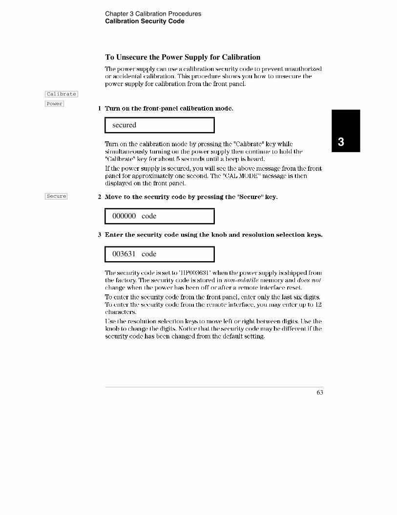
Chapter 3 Calibration Procedures Calibration Security Code
3
To Unsecure the Power Supply for Calibration
The power supply can use a calibration security code to prevent unauthorized
or accidental calibration. This procedure shows you how to unsecure the
power supply for calibration from the front panel.
1 Turn on the front-panel calibration mode.
Turn on the calibration mode by pressing the "Calibrate" key while
simultaneously turning on the power supply then continue to hold the
"Calibrate" key for about 5 seconds until a beep is heard.
If the power supply is secured, you will see the above message from the front
panel for approximately one second. The "CAL MODE'' message is then
displayed on the front panel.
2 Move to the security code by pressing the "Secure" key.
3 Enter the security code using the knob and resolution selection keys.
The security code is set to "HP003631" when the power supply is shipped from
the factory. The security code is stored in non-volatile memory and does not
change when the power has been off or after a remote interface reset.
To enter the security code from the front panel, enter only the last six digits.
To enter the security code from the remote interface, you may enter up to 12
characters.
Use the resolution selection keys to move left or right between digits. Use the
knob to change the digits. Notice that the security code may be different if the
security code has been changed from the default setting.
secured
000000 code
003631 code
Calibrate
Power
Secure
63
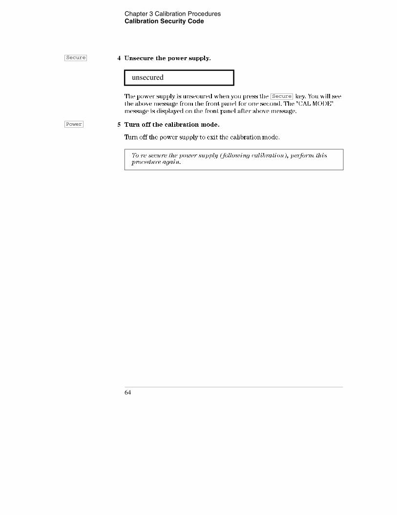
Chapter 3 Calibration Procedures Calibration Security Code
4 Unsecure the power supply.
The power supply is unsecured when you press the key. You will see
the above message from the front panel for one second. The "CAL MODE"
message is displayed on the front panel after above message.
5 Turn off the calibration mode.
Turn off the power supply to exit the calibration mode.
unsecured
To re-secure the power supply (following calibration), perform this procedure again.
Secure
Secure
Power
64
Chapter 3 Calibration Procedures Calibration Security Code
3
To Unsecure the Power Supply Without the Security Code
To unsecure the power supply without the correct security code (when you
forget the security code), follow the steps below. See "Electrostatic Discharge
(ESD) Precautions" in chapter 5 before beginning this procedure.
1 Disconnect the power cord and all load connections from front terminals.
2 Remove the instrument cover. Refer to the disassembly drawing on page 123.
3 Connect the power cord and turn on the calibration mode by pressing the "Calibrate" key while simultaneously turning on the power supply then continue to hold the "Calibrate" key for about 5 seconds until a beep is heard. Be careful not to touch the power line connections.
4 Apply a short between the two exposed metal pads on JP1 (located near main controller U17 on the top board). The exposed metal pads are outlined with a small rectangular silkscreen. (See the component locator drawing for the E3631-60002 top PC board on page 124.)
5 While maintaining the short, move to the security code and enter any unsecure code in the calibration mode. The power supply is now unsecured.
6 Remove the short at JP1. (An error occurs if not removed.)
7 Turn off and reassemble the power supply.
Now you can enter a new security code. Be sure you take note of the new
security code.
65
Chapter 3 Calibration Procedures Calibration Count
Calibration Count
The calibration count feature provides an independent "serialization" of your
calibrations. You can determine the number of times that your power supply
has been calibrated. By monitoring the calibration count, you can determine
whether an unauthorized calibration has been performed. Since the value
increments by one for each calibration parameter (see Table 3-3 on the next
page), a complete calibration increases the value by 6 counts.
• The calibration count is stored in non-volatile memory and does not change
when power has been off or after a remote interface reset. Your power
supply was calibrated before it left the factory. When you receive the power
supply, read the calibration count to determine its value.
• The calibration count increments up to a maximum of 32,767 after which it
wraps around to 0. No way is provided to program or reset the calibration
count.
Calibration Message
You can use the calibration message feature to record calibration information
about your power supply. For example, you can store such information as the
last calibration date, the next calibration due date, the power supply's serial
number, or even the name and phone number of the person to contact for a
new calibration.
You can record and read information in the calibration message from the
remote interface only.
• The calibration message may contain up to 40 characters.
• The calibration message is stored in non-volatile memory and does not
change when power has been off or after a remote interface reset.
66

Chapter 3 Calibration Procedures General Calibration/Adjustment Procedure
3
General Calibration/Adjustment Procedure
The calibration procedures from the front panel are described in this section.
For output voltage calibration, disconnect all loads from the power supply and
connect a DVM across the output terminals to be calibrated. For output current
calibration, disconnect all loads from the power supply, connect an
appropriate current monitoring resistor across the output terminals to be
calibrated, and connect a DVM across the terminals of the monitoring resistor.
The following table shows calibration parameters and points which should be
used to calibrate the output voltage and current for each of the three outputs.
Table 3-3. Parameters for Calibration
N o t e You can terminate any CAL SETUP without changing its calibration constants by turning off power.
Output Calibration Parameter Voltage/Current
Calibration Point mnemonic
+6V output
CAL SETUP 1 VoltageV LO
V HI
CAL SETUP 2 CurrentI LO
I HI
+25V output
CAL SETUP 3 VoltageV LO
V HI
CAL SETUP 4 CurrentV LO
I HI
-25V output
CAL SETUP 5 VoltageV LO
V HI
CAL SETUP 6 CurrentI LO
I HI
67
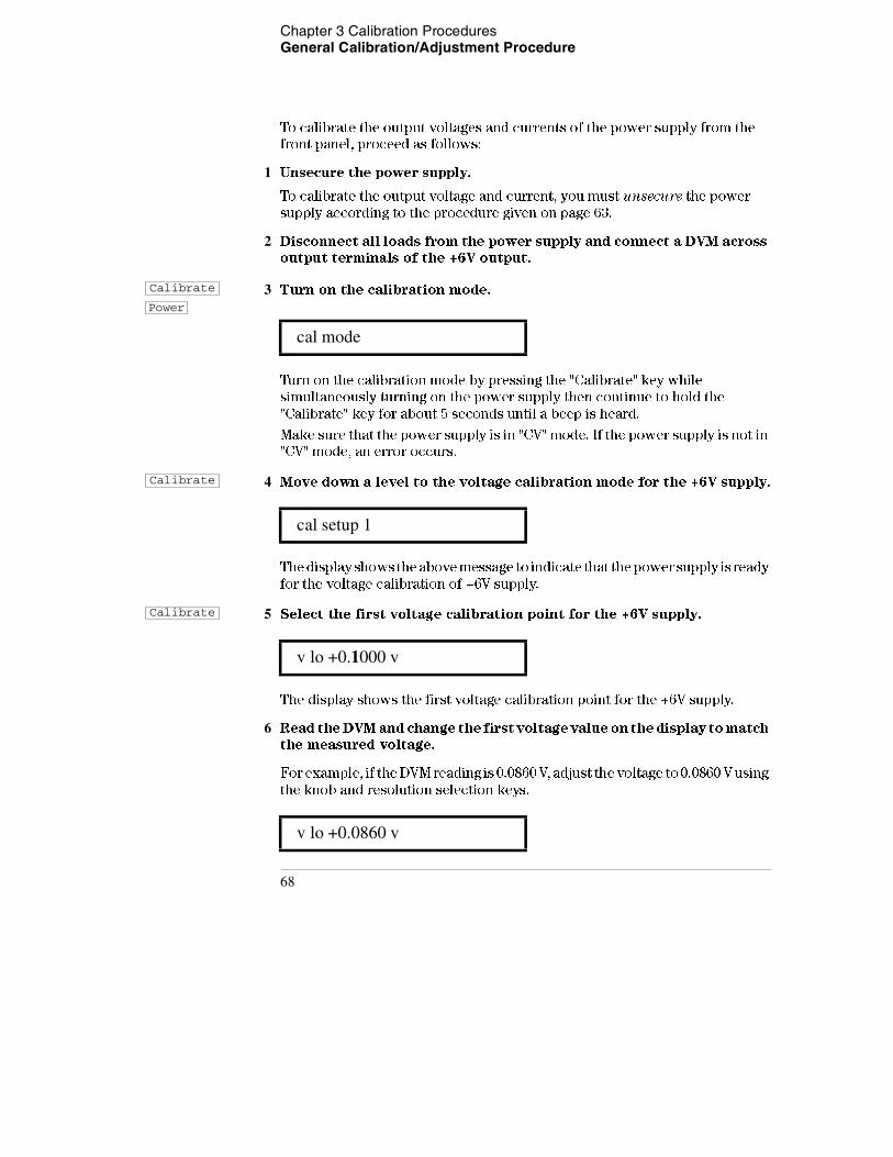
Chapter 3 Calibration Procedures General Calibration/Adjustment Procedure
To calibrate the output voltages and currents of the power supply from the
front panel, proceed as follows:
1 Unsecure the power supply.
To calibrate the output voltage and current, you must unsecure the power
supply according to the procedure given on page 63.
2 Disconnect all loads from the power supply and connect a DVM across
output terminals of the +6V output.
3 Turn on the calibration mode.
Turn on the calibration mode by pressing the "Calibrate" key while
simultaneously turning on the power supply then continue to hold the
"Calibrate" key for about 5 seconds until a beep is heard.
Make sure that the power supply is in "CV" mode. If the power supply is not in
"CV" mode, an error occurs.
4 Move down a level to the voltage calibration mode for the +6V supply.
The display shows the above message to indicate that the power supply is ready
for the voltage calibration of +6V supply.
5 Select the first voltage calibration point for the +6V supply.
The display shows the first voltage calibration point for the +6V supply.
6 Read the DVM and change the first voltage value on the display to match
the measured voltage.
For example, if the DVM reading is 0.0860 V, adjust the voltage to 0.0860 V using
the knob and resolution selection keys.
cal mode
cal setup 1
v lo +0.1000 v
v lo +0.0860 v
Calibrate
Power
Calibrate
Calibrate
68
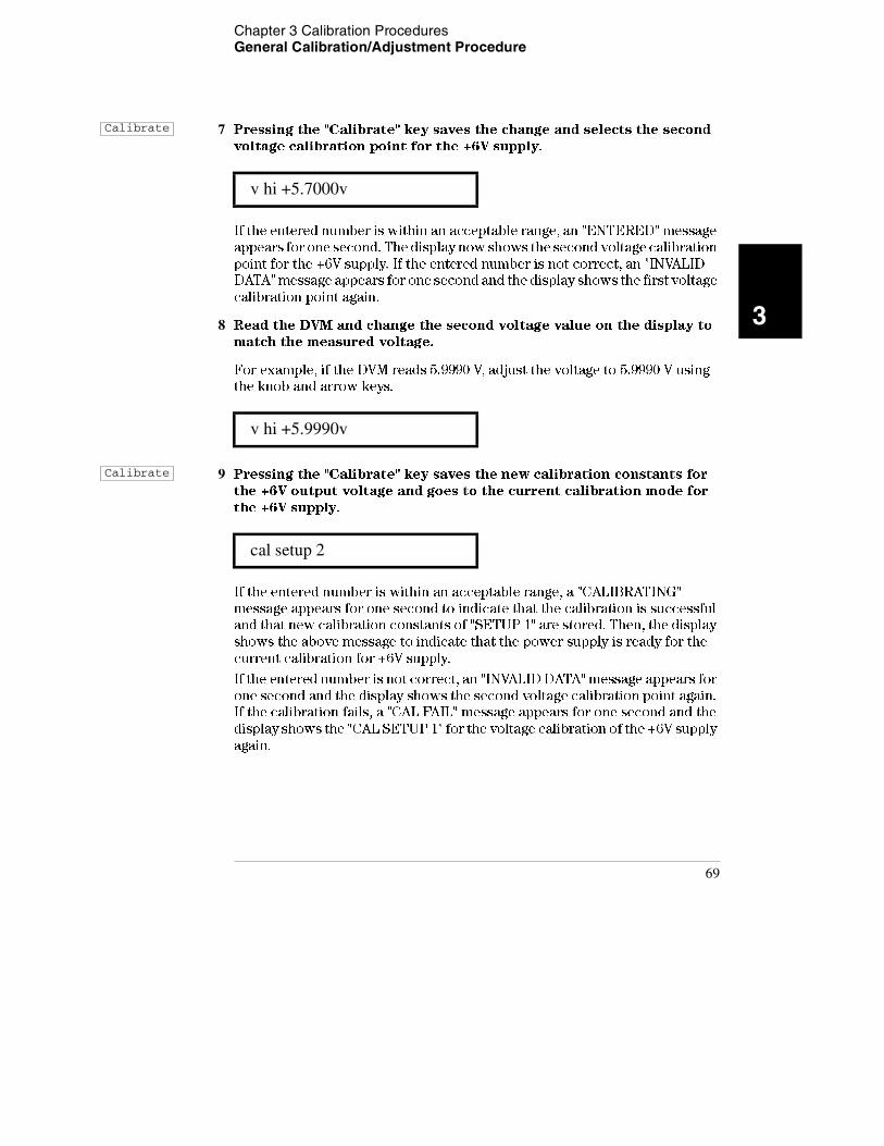
Chapter 3 Calibration Procedures General Calibration/Adjustment Procedure
3
7 Pressing the "Calibrate" key saves the change and selects the second
voltage calibration point for the +6V supply.
If the entered number is within an acceptable range, an "ENTERED" message
appears for one second. The display now shows the second voltage calibration
point for the +6V supply. If the entered number is not correct, an "INVALID
DATA" message appears for one second and the display shows the first voltage
calibration point again.
8 Read the DVM and change the second voltage value on the display to
match the measured voltage.
For example, if the DVM reads 5.9990 V, adjust the voltage to 5.9990 V using
the knob and arrow keys.
9 Pressing the "Calibrate" key saves the new calibration constants for
the +6V output voltage and goes to the current calibration mode for
the +6V supply.
If the entered number is within an acceptable range, a "CALIBRATING"
message appears for one second to indicate that the calibration is successful
and that new calibration constants of "SETUP 1" are stored. Then, the display
shows the above message to indicate that the power supply is ready for the
current calibration for +6V supply.
If the entered number is not correct, an "INVALID DATA" message appears for
one second and the display shows the second voltage calibration point again.
If the calibration fails, a "CAL FAIL" message appears for one second and the
display shows the "CAL SETUP 1" for the voltage calibration of the +6V supply
again.
v hi +5.7000v
v hi +5.9990v
cal setup 2
Calibrate
Calibrate
69
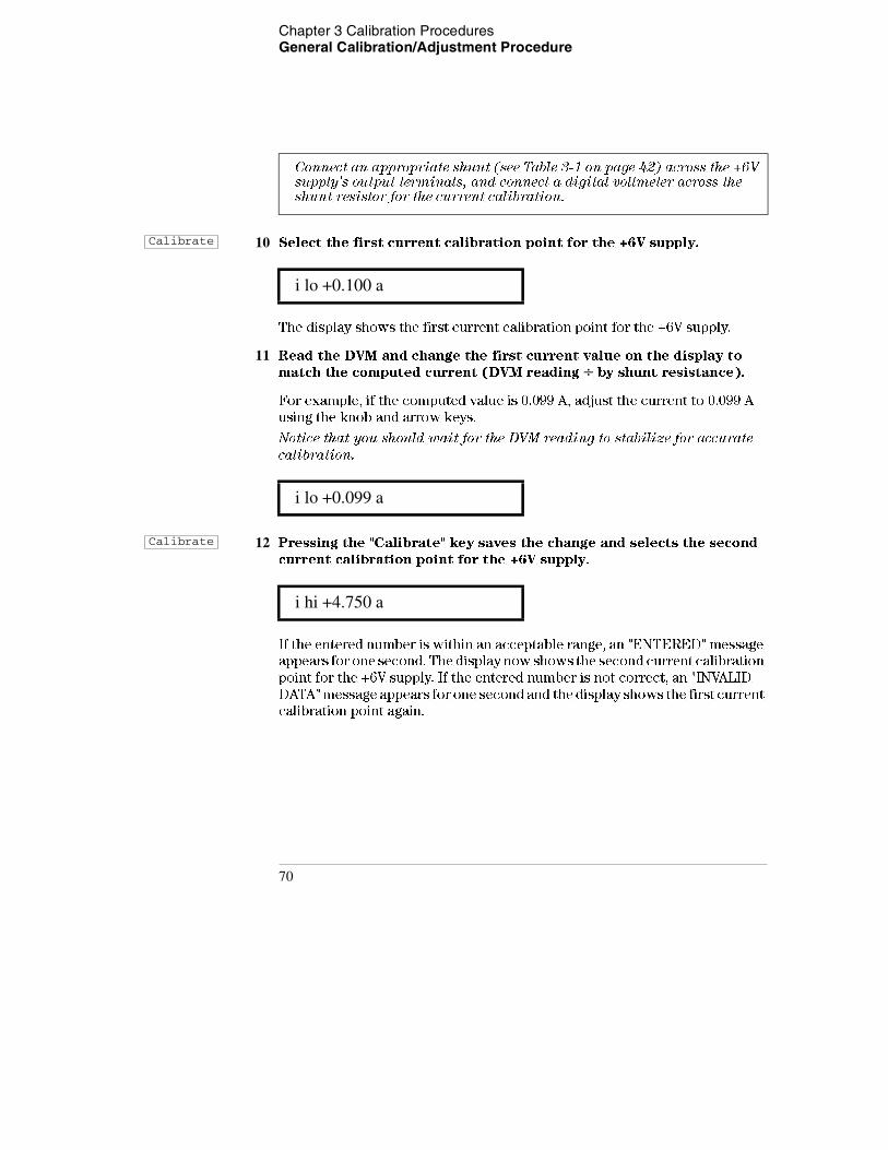
Chapter 3 Calibration Procedures General Calibration/Adjustment Procedure
10 Select the first current calibration point for the +6V supply.
The display shows the first current calibration point for the +6V supply.
11 Read the DVM and change the first current value on the display to
match the computed current (DVM reading ÷ by shunt resistance).
For example, if the computed value is 0.099 A, adjust the current to 0.099 A
using the knob and arrow keys.
Notice that you should wait for the DVM reading to stabilize for accurate
calibration.
12 Pressing the "Calibrate" key saves the change and selects the second
current calibration point for the +6V supply.
If the entered number is within an acceptable range, an "ENTERED" message
appears for one second. The display now shows the second current calibration
point for the +6V supply. If the entered number is not correct, an "INVALID
DATA" message appears for one second and the display shows the first current
calibration point again.
Connect an appropriate shunt (see Table 3-1 on page 42) across the +6V supply's output terminals, and connect a digital voltmeter across the shunt resistor for the current calibration.
i lo +0.100 a
i lo +0.099 a
i hi +4.750 a
Calibrate
Calibrate
70
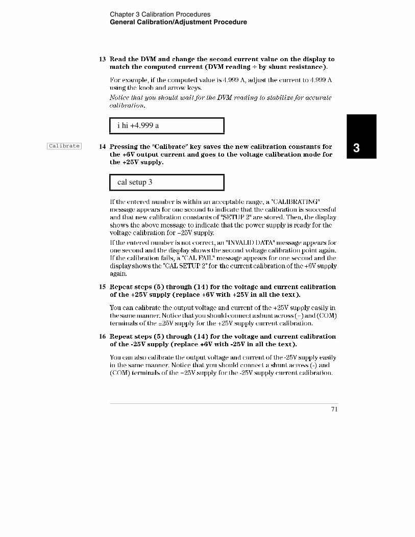
Chapter 3 Calibration Procedures General Calibration/Adjustment Procedure
3
13 Read the DVM and change the second current value on the display to
match the computed current (DVM reading ÷ by shunt resistance).
For example, if the computed value is 4.999 A, adjust the current to 4.999 A
using the knob and arrow keys.
Notice that you should wait for the DVM reading to stabilize for accurate
calibration.
14 Pressing the "Calibrate" key saves the new calibration constants for
the +6V output current and goes to the voltage calibration mode for
the +25V supply.
If the entered number is within an acceptable range, a "CALIBRATING"
message appears for one second to indicate that the calibration is successful
and that new calibration constants of "SETUP 2" are stored. Then, the display
shows the above message to indicate that the power supply is ready for the
voltage calibration for +25V supply.
If the entered number is not correct, an "INVALID DATA" message appears for
one second and the display shows the second voltage calibration point again.
If the calibration fails, a "CAL FAIL" message appears for one second and the
display shows the "CAL SETUP 2" for the current calibration of the +6V supply
again.
15 Repeat steps (5) through (14) for the voltage and current calibration
of the +25V supply (replace +6V with +25V in all the text).
You can calibrate the output voltage and current of the +25V supply easily in
the same manner. Notice that you should connect a shunt across (+) and (COM)
terminals of the ±25V supply for the +25V supply current calibration.
16 Repeat steps (5) through (14) for the voltage and current calibration
of the -25V supply (replace +6V with -25V in all the text).
You can also calibrate the output voltage and current of the -25V supply easily
in the same manner. Notice that you should connect a shunt across (-) and
(COM) terminals of the ±25V supply for the -25V supply current calibration.
i hi +4.999 a
cal setup 3
Calibrate
71

Chapter 3 Calibration Procedures Aborting a Calibration in Progress
Aborting a Calibration in Progress
Sometimes it may be necessary to abort a calibration after the procedure has
already been initiated. You can abort a calibration at any time by turning the
power supply off from the front panel. When performing a calibration from the
remote interface, you can abort a calibration by issuing a remote interface
device clear message or by pressing the front-panel "Local" key.
72
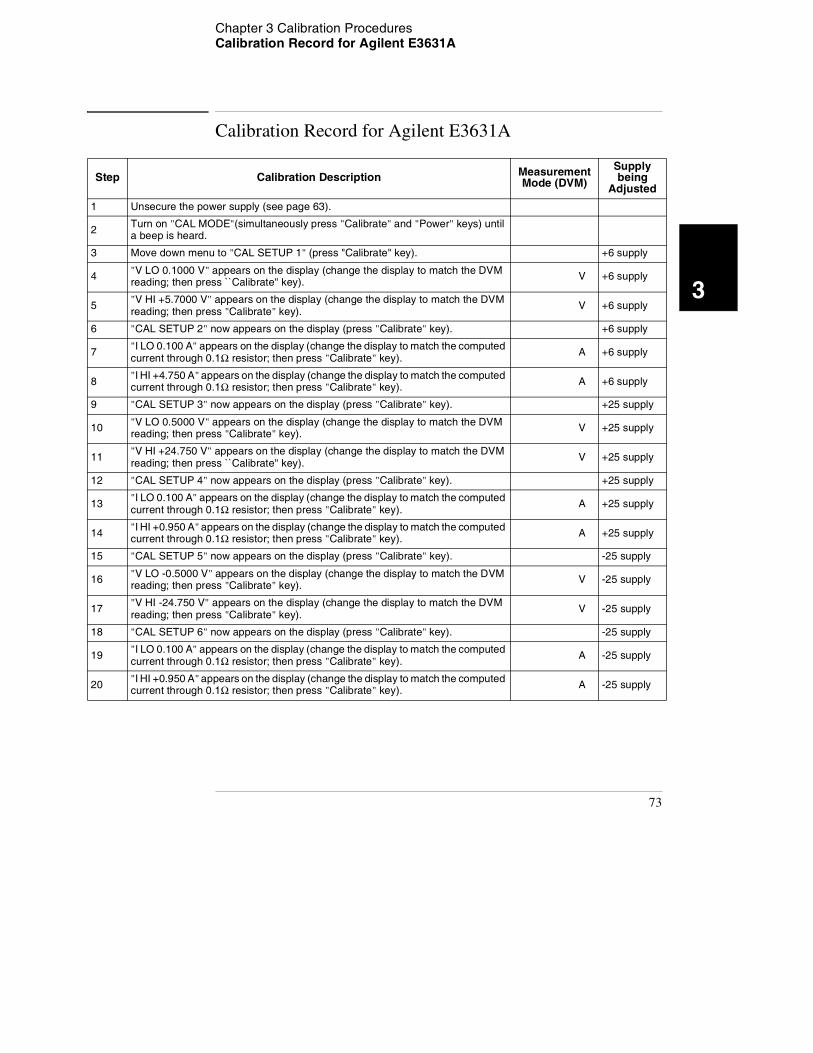
Chapter 3 Calibration Procedures Calibration Record for Agilent E3631A
3
Calibration Record for Agilent E3631A
Step Calibration Description Measurement Mode (DVM)
Supply being
Adjusted
1 Unsecure the power supply (see page 63).
2 Turn on "CAL MODE"(simultaneously press "Calibrate" and "Power" keys) until a beep is heard.
3 Move down menu to "CAL SETUP 1" (press "Calibrate" key). +6 supply
4 "V LO 0.1000 V" appears on the display (change the display to match the DVM reading; then press ``Calibrate'' key). V +6 supply
5 "V HI +5.7000 V" appears on the display (change the display to match the DVM reading; then press "Calibrate" key). V +6 supply
6 "CAL SETUP 2" now appears on the display (press "Calibrate" key). +6 supply
7 "I LO 0.100 A" appears on the display (change the display to match the computed current through 0.1Ω resistor; then press "Calibrate" key). A +6 supply
8 "I HI +4.750 A" appears on the display (change the display to match the computed current through 0.1Ω resistor; then press "Calibrate" key). A +6 supply
9 "CAL SETUP 3" now appears on the display (press "Calibrate" key). +25 supply
10 "V LO 0.5000 V" appears on the display (change the display to match the DVM reading; then press "Calibrate" key). V +25 supply
11 "V HI +24.750 V" appears on the display (change the display to match the DVM reading; then press ``Calibrate'' key). V +25 supply
12 "CAL SETUP 4" now appears on the display (press "Calibrate" key). +25 supply
13 "I LO 0.100 A" appears on the display (change the display to match the computed current through 0.1Ω resistor; then press "Calibrate" key). A +25 supply
14 "I HI +0.950 A" appears on the display (change the display to match the computed current through 0.1Ω resistor; then press "Calibrate" key). A +25 supply
15 "CAL SETUP 5" now appears on the display (press "Calibrate" key). -25 supply
16 "V LO -0.5000 V" appears on the display (change the display to match the DVM reading; then press "Calibrate" key). V -25 supply
17 "V HI -24.750 V" appears on the display (change the display to match the DVM reading; then press "Calibrate" key). V -25 supply
18 "CAL SETUP 6" now appears on the display (press "Calibrate" key). -25 supply
19 "I LO 0.100 A" appears on the display (change the display to match the computed current through 0.1Ω resistor; then press "Calibrate" key). A -25 supply
20 "I HI +0.950 A" appears on the display (change the display to match the computed current through 0.1Ω resistor; then press "Calibrate" key). A -25 supply
73
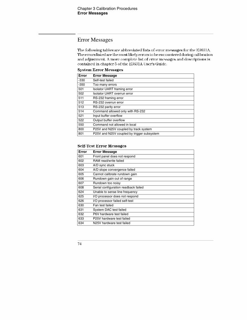
Chapter 3 Calibration Procedures Error Messages
Error Messages
The following tables are abbreviated lists of error messages for the E3631A.
The errors listed are the most likely errors to be encountered during calibration
and adjustment. A more complete list of error messages and descriptions is
contained in chapter 5 of the E3631A User's Guide.
System Error Messages
Self-Test Error Messages
Error Error Message-330 Self-test failed-350 Too many errors501 Isolator UART framing error502 Isolator UART overrun error511 RS-232 framing error512 RS-232 overrun error513 RS-232 parity error514 Command allowed only with RS-232521 Input buffer overflow522 Output buffer overflow550 Command not allowed in local800 P25V and N25V coupled by track system801 P25V and N25V coupled by trigger subsystem
Error Error Message601 Front panel does not respond602 RAM read/write failed603 A/D sync stuck604 A/D slope convergence failed605 Cannot calibrate rundown gain606 Rundown gain out of range607 Rundown too noisy608 Serial configuration readback failed624 Unable to sense line frequency625 I/O processor does not respond626 I/O processor failed self-test630 Fan test failed631 System DAC test failed632 P6V hardware test failed633 P25V hardware test failed634 N25V hardware test failed
74
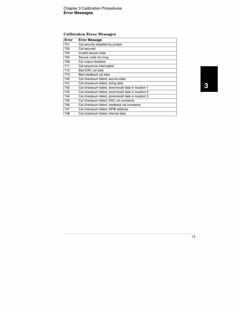
Chapter 3 Calibration Procedures Error Messages
3
Calibration Error Messages
Error Error Message701 Cal security disabled by jumper702 Cal secured703 Invalid secure code704 Secure code too long708 Cal output disabled711 Cal sequence interrupted712 Bad DAC cal data713 Bad readback cal data740 Cal checksum failed, secure state741 Cal checksum failed, string data742 Cal checksum failed, store/recall data in location 1743 Cal checksum failed, store/recall data in location 2744 Cal checksum failed, store/recall data in location 3745 Cal checksum failed, DAC cal constants746 Cal checksum failed, readback cal constants747 Cal checksum failed, GPIB address748 Cal checksum failed, internal data
75
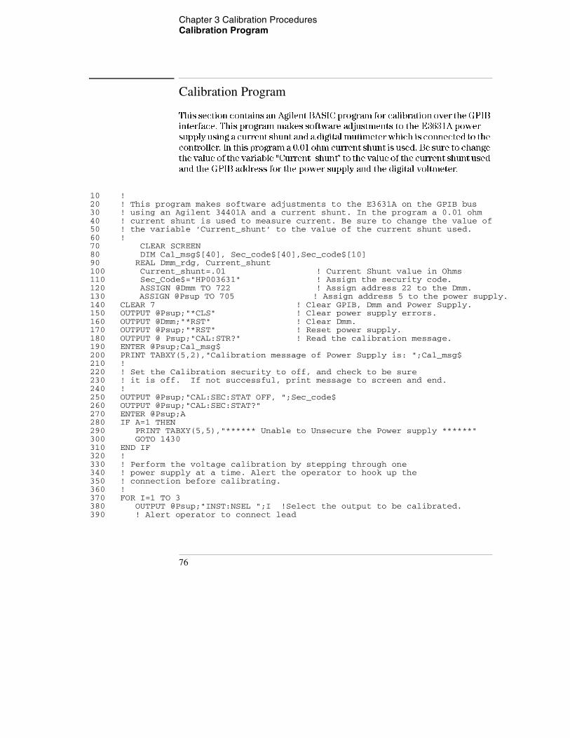
Chapter 3 Calibration Procedures Calibration Program
Calibration Program
This section contains an Agilent BASIC program for calibration over the GPIB
interface. This program makes software adjustments to the E3631A power
supply using a current shunt and a digital mutimeter which is connected to the
controller. In this program a 0.01 ohm current shunt is used. Be sure to change
the value of the variable "Current_shunt" to the value of the current shunt used
and the GPIB address for the power supply and the digital voltmeter.
10 !20 ! This program makes software adjustments to the E3631A on the GPIB bus 30 ! using an Agilent 34401A and a current shunt. In the program a 0.01 ohm 40 ! current shunt is used to measure current. Be sure to change the value of50 ! the variable ’Current_shunt’ to the value of the current shunt used.60 !70 CLEAR SCREEN80 DIM Cal_msg$[40], Sec_code$[40],Sec_code$[10]90 REAL Dmm_rdg, Current_shunt100 Current_shunt=.01 ! Current Shunt value in Ohms110 Sec_Code$="HP003631" ! Assign the security code.120 ASSIGN @Dmm TO 722 ! Assign address 22 to the Dmm.130 ASSIGN @Psup TO 705 ! Assign address 5 to the power supply.140 CLEAR 7 ! Clear GPIB, Dmm and Power Supply.150 OUTPUT @Psup;"*CLS" ! Clear power supply errors.160 OUTPUT @Dmm;"*RST" ! Clear Dmm.170 OUTPUT @Psup;"*RST" ! Reset power supply.180 OUTPUT @ Psup;"CAL:STR?" ! Read the calibration message.190 ENTER @Psup;Cal_msg$200 PRINT TABXY(5,2),"Calibration message of Power Supply is: ";Cal_msg$210 !220 ! Set the Calibration security to off, and check to be sure230 ! it is off. If not successful, print message to screen and end.240 !250 OUTPUT @Psup;"CAL:SEC:STAT OFF, ";Sec_code$260 OUTPUT @Psup;"CAL:SEC:STAT?"270 ENTER @Psup;A280 IF A=1 THEN290 PRINT TABXY(5,5),"****** Unable to Unsecure the Power supply ******"300 GOTO 1430310 END IF320 !330 ! Perform the voltage calibration by stepping through one340 ! power supply at a time. Alert the operator to hook up the350 ! connection before calibrating.360 !370 FOR I=1 TO 3380 OUTPUT @Psup;"INST:NSEL ";I !Select the output to be calibrated.390 ! Alert operator to connect lead
76
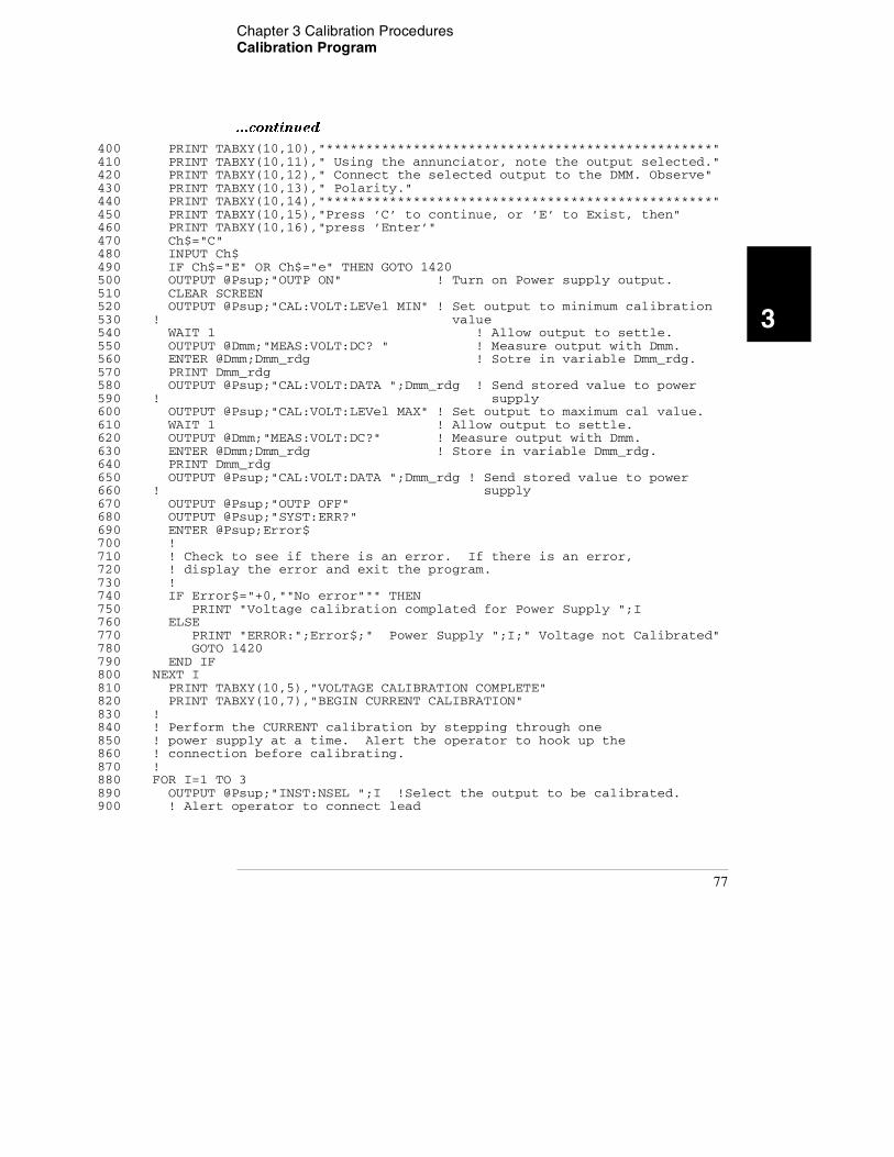
Chapter 3 Calibration Procedures Calibration Program
3
...continued
400 PRINT TABXY(10,10),"*************************************************"410 PRINT TABXY(10,11)," Using the annunciator, note the output selected."420 PRINT TABXY(10,12)," Connect the selected output to the DMM. Observe"430 PRINT TABXY(10,13)," Polarity."440 PRINT TABXY(10,14),"*************************************************"450 PRINT TABXY(10,15),"Press ’C’ to continue, or ’E’ to Exist, then"460 PRINT TABXY(10,16),"press ’Enter’"470 Ch$="C"480 INPUT Ch$490 IF Ch$="E" OR Ch$="e" THEN GOTO 1420500 OUTPUT @Psup;"OUTP ON" ! Turn on Power supply output.510 CLEAR SCREEN520 OUTPUT @Psup;"CAL:VOLT:LEVel MIN" ! Set output to minimum calibration530 ! value540 WAIT 1 ! Allow output to settle.550 OUTPUT @Dmm;"MEAS:VOLT:DC? " ! Measure output with Dmm.560 ENTER @Dmm;Dmm_rdg ! Sotre in variable Dmm_rdg.570 PRINT Dmm_rdg580 OUTPUT @Psup;"CAL:VOLT:DATA ";Dmm_rdg ! Send stored value to power590 ! supply600 OUTPUT @Psup;"CAL:VOLT:LEVel MAX" ! Set output to maximum cal value.610 WAIT 1 ! Allow output to settle.620 OUTPUT @Dmm;"MEAS:VOLT:DC?" ! Measure output with Dmm.630 ENTER @Dmm;Dmm_rdg ! Store in variable Dmm_rdg.640 PRINT Dmm_rdg650 OUTPUT @Psup;"CAL:VOLT:DATA ";Dmm_rdg ! Send stored value to power660 ! supply670 OUTPUT @Psup;"OUTP OFF"680 OUTPUT @Psup;"SYST:ERR?"690 ENTER @Psup;Error$700 !710 ! Check to see if there is an error. If there is an error,720 ! display the error and exit the program.730 !740 IF Error$="+0,""No error""" THEN750 PRINT "Voltage calibration complated for Power Supply ";I760 ELSE770 PRINT "ERROR:";Error$;" Power Supply ";I;" Voltage not Calibrated"780 GOTO 1420790 END IF800 NEXT I810 PRINT TABXY(10,5),"VOLTAGE CALIBRATION COMPLETE"820 PRINT TABXY(10,7),"BEGIN CURRENT CALIBRATION"830 !840 ! Perform the CURRENT calibration by stepping through one850 ! power supply at a time. Alert the operator to hook up the860 ! connection before calibrating.870 !880 FOR I=1 TO 3890 OUTPUT @Psup;"INST:NSEL ";I !Select the output to be calibrated.900 ! Alert operator to connect lead
77
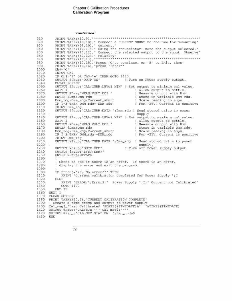
Chapter 3 Calibration Procedures Calibration Program
...continued
910 PRINT TABXY(10,9),"***************************************************"920 PRINT TABXY(10,10)," Connect a CURRENT SHUNT to the Dmm for measuring"930 PRINT TABXY(59,10)," current."940 PRINT TABXY(10,11)," Using the annunciator, note the output selected."950 PRINT TABXY(10,12)," Connect the selected output to the shunt. Observe"960 PRINT TABXY(60,12)," Polarity"970 PRINT TABXY(10,13),"**************************************************"980 PRINT TABXY(10,15),"Press ’C’to continue, or ’E’ to Exit, then"990 PRINT TABXY(10,16),"press ’Enter’"1000 Ch$="C"1010 INPUT Ch$1020 IF Ch$="E" OR Ch$="e" THEN GOTO 14201030 OUTPUT @Psup;"OUTP ON" ! Turn on Power supply output.1040 CLEAR SCREEN1050 OUTPUT @Psup;"CAL:CURR:LEVel MIN" ! Set output to minimum cal value.1060 WAIT 1 ! Allow output to settle.1070 OUTPUT @Dmm;"MEAS:VOLT:DC? " ! Measure output with Dmm.1080 ENTER @Dmm;Dmm_rdg ! Store in variable Dmm_rdg.1090 Dmm_rdg=Dmm_rdg/Current_shunt ! Scale reading to amps.1100 IF I=3 THEN DMM_rdg=-DMM_rdg ! For -25V, Current is positive1110 PRINT Dmm_rdg1120 OUTPUT @Psup;"CAL:CURR:DATA ";Dmm_rdg ! Send stored value to power1130 ! supply1140 OUTPUT @Psup;"CAL:CURR:LEVel MAX" ! Set output to maximum cal value.1150 WAIT 1 ! Allow output to settle.1160 OUTPUT @Dmm;"MEAS:VOLT:DC? " ! Measure output with Dmm.1170 ENTER @Dmm;Dmm_rdg ! Store in variable Dmm_rdg.1180 Dmm_rdg=Dmm_rdg/Current_shunt ! Scale reading to amps.1190 IF I=3 THEN DMM_rdg=-DMM_rdg ! For -25V, Current is positive1200 PRINT Dmm_rdg1210 OUTPUT @Psup;"CAL:CURR:DATA ";Dmm_rdg ! Send stored value to power1220 ! supply.1230 OUTPUT @Psup;"OUTP OFF" ! Turn off Power supply output.1240 OUTPUT @Psup;"SYST:ERR?"1250 ENTER @Psup;Error$1260 !1270 ! Check to see if there is an error. If there is an error,1280 ! display the error and exit the program.1290 !1300 IF Error$="+0, No error""" THEN1310 PRINT "Current calibration completed for Power Supply ";I1320 ELSE1330 PRINT "ERROR:";Error$;" Power Supply ";I;" Current not Calibrated"1340 GOTO 14201350 END IF1360 NEXT I1370 CLEAR SCREEN1380 PRINT TABXY(10,5),"CURRENT CALIBRATION COMPLETE"1390 ! Create a time stamp and output to power supply1400 Cal_msg$_"Last Calibrated "$DATE$(TIMEDATE)&" "&TIME$(TIMEDATE)1410 OUTPUT @Psup;"CAL:STR """;Cal_msg$;""""1420 OUTPUT @Psup;"CAL:SEC:STAT ON, ";Sec_code$1430 END
78
Chapter 3 Calibration Procedures Calibration Program
3
79

Chapter 3 Calibration Procedures Calibration Program
80
4
4
Theory of Operation
Theory of Operation
This chapter provides block diagram level descriptions of the power supply.
The descriptions provide a basic understanding of circuit operation and are
intended as an aid in troubleshooting. It is assumed in the following discussions
that you are familiar with the operating and programming instructions
presented in the E3631A User's Guide. Subjects covered include the following:
• Block Diagram Overview, page 81
• AC Input and Bias Supplies, page 83
• Floating Logic, page 84
• D-to-A Converter, page 86
• A-to-D Converter, page 87
• Power Mesh and Control, page 88
• Earth-Referenced Logic, page 90
• Front Panel, page 90
80
Chapter 4 Theory of Operation Block Diagram Overview
4
Block Diagram Overview
This discussion pertains to the block diagram on the next page. The power
supply's circuitry is divided into two major blocks: the floating circuitry and
the ground referenced circuitry. All power mesh and control circuits, display
circuit, and digital circuits are contained in the floating circuitry. This circuitry
also contains the power supply's main controller. The ground referenced
circuitry provides the interface between the user and the power supply.
The floating circuitry can be viewed in four pieces; the DAC system, the digital
logic section (floating logic), the power mesh and control section (+6V and
±25V power circuits), and the front panel (display and keyboard) section.
The floating logic receives digital signals from the earth-referenced logic and
the DAC converts them to analog signals which are sent to the power control
circuits in order to program the power supply's output voltage and current.
The power supply can also be commanded to send measurement and status
data back to the remote interface controller and/or the VFD (vacuum
fluorescent display) display on the front panel. The data is processed and sent
back via the floating logic and earth-referenced logic.
The power mesh and control circuits contains voltage and current control
circuits which allows the power supply to operate in either the constant voltage
(CV) or constant current (CC) mode. The control circuits compare the power
supply's output voltage or current with the programmed value and generates
a control signal which varies the conduction of the series pass transistor to
raise or lower the output as required.
The front panel circuits consist of VFD control, display high voltage drivers,
and keyboard scanning. Communication between the front panel and floating
logic circuits is accomplished through a 4-wire bi-directional serial interface.
The ground referenced circuitry uses a controller configured as a slave to the
main controller. This controller establishes external I/O communication with
the main controller through a bi-directional, optically isolated, serial
communications link. The earth referenced controller controls low-level GPIB
(IEEE-488) and RS-232 interface operation.
Separate reference and bias supplies are provided for the floating and ground
reference circuitry. The front panel operates from the floating circuitry with
its logic common different from the main controller logic common.
81
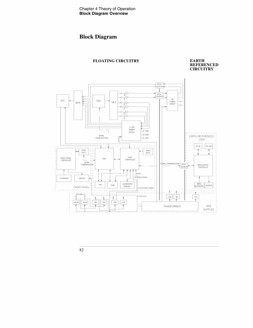
Chapter 4 Theory of Operation Block Diagram Overview
Block Diagram
EARTHREFERENCEDCIRCUITRY
FLOATING CIRCUITRY
82
Chapter 4 Theory of Operation AC Input and Bias Supplies
4
AC Input and Bias Supplies
Referring to the schematic shown on page 127, the ac mains are connected by
a fused power module. This module incorporates the functions of mains
connection, fusing, and line voltage selection (100/115/230 Vac). The line
voltage selection function of the module selects which primary winding of
power transformer T1 is energized. The transformer secondary windings are
connected to the main pc board through connectors.
The bias supplies are consists of four sections; ±15 Vdc for the +6V power
circuits; ±15 Vdc, +5 Vdc and -5.1 Vdc for the ±25V power circuits and floating
logic; ±16.4 Vdc for the display; and +5 Vdc for the earth referenced logic.
Power-on reset signals are provided by the +5 Vdc supply of the floating logic.
The ±15 Vdc for the +6V power circuits are produced by rectifiers CR15 and
CR16, filter capacitors C43 and C44, and voltage regulators U24 and U25 on
the bottom board. These supplies provide bias voltages for the +6V power
circuits.
The ±16.4 Vdc for the display circuits are produced by rectifier CR20, filter
capacitors C44 and C45, and voltage regulators U24 and U25 on the top board.
A separate winding of T1 provides a center tapped 6 Vrms filament supply for
the display.
The ±15 Vdc for the ±25V power circuits are derived from ±16.4 Vdc by diodes
CR15 through CR18 on the top board. These supplies provide bias voltages for
the ±25V power circuits.
The floating +5 Vdc and -5.1 Vdc supplies are produced from ±16.4 Vdc
supplies. VR2 on the top board forms a clamp circuit to provide over voltage
protection in the event of a regulator failure. The ADC REF signal is derived
from +15 Vdc supply and the TURN_ON RESET signal is derived from +5 Vdc
supply. The FAN FAIL signal is asserted when the fan current through R73 on
the top board is not detected. The TURN_ON RESET signal holds the main
controller and other logic in a reset state until after the +5 Vdc logic power is
fully operational. This signal is generally active only following application of
line power to the instrument.
The +5V dc earth referenced supply is produced by rectifier CR3, filter
capacitor C15, and regulator U11 on the bottom board. The GPIB (IEEE-488)
and RS-232 computer interfaces are powered from this supply.
83
Chapter 4 Theory of Operation Floating Logic
Floating Logic
Referring to the schematic shown on page 128, the floating common logic
controls operation of the entire instrument. All output functions and bus
command interpretation is performed in the main controller U17. The front
panel and the earth referenced logic operate as slaves to U17. The floating
common logic is comprised of the main controller U17, custom gate array U16,
the program ROM U14, RAM U15, calibration EEPROM U18, and the 12 MHz
clock oscillator Y1 on the top board . Non-volatile EEPROM U18 stores
calibration constants, calibration secure code, and calibration count. Power-
on reset is provided to the main controller by the voltage regulator U1 on the
top board.
The main controller U17 is a 16-bit micro controller. It controls such features
as receive and transmit serial port, timer/counter ports, an 8-bit pulse width
modulated DAC port, and selectable input 10-bit successive approximation a-
to-d convert ports. A conventional address/data bus is used to transfer data
between the main controller and external ROM and RAM. When the address
latch enable (ALE) signal goes high, address data is present on the address/
data bus. ASIC U16 latches the address data and decodes the correct chip
enable (low true) for external ROM and RAM accesses and for read/write
accesses to the internal registers of U16. The system memory map is shown
below.
Program ROM U14 contains four 64k x 8 data banks of data. Banks are selected
by controlling A16 and A17 ROM address bits directly from the main controller
port bits.
Custom gate array U16 performs address latching and memory map decoding
functions as discussed above. In addition, U16 contains a variety of internal
read/write registers. The read (XRD) and write (XWR) signals transfer data out
of and into U16 when it is addressed. There are four internal registers in U16:
an internal configuration register, an 8 bit counter register, a serial transmit/
receive register, and an internal status register.
The counter register is used to capture the ADC slope count at the COMP input.
The COMP input functions as both a clocked comparator and the slope counter
input for the ADC. In both cases the counter register captures the lower 8 bits
of a 24-bit counter. The upper 16 bits of the count are captured by the SYNC
input to U17.
0000H - 1FF7H U15 8k x 8 RAM 1FF8H - 1FFFH U16 Gate Array 2000H - FFFFH U14 Program ROM
84

Chapter 4 Theory of Operation Floating Logic
4
The serial register is used to send and receive serial data bytes from the main
controller to the DAC system, or to communicate with the front panel
controller. The serial register is multiplexed to these two circuits. The
transmission rate is selected to 1.5 M bits/second for the DAC system and 93.75
k bits/second for communication with the front panel controller. The general
serial interface is a 3-bit interface as shown below.
Serial data is received simultaneously as serial data is clocked out. Front panel
data is exchanged in both directions whenever a byte is sent from U16 on the
top board. The input data of DAC is strobed to outputs by U17 signal SERSTB.
Interrupts from the front panel are detected by U16 and signaled to the CHINT.
The main controller FPINT signals the front panel controller that U16 has data
to send.
The power supply's calibration correction data are stored in a 128 x 16 bit non-
volatile electrically erasable ROM U18 on the top board. This non-volatile ROM
read/write data is accessed by a 4-bit serial protocol controlled by U17.
The main controller has an on-chip 10-bit successive approximation ADC. The
FLASH input is used to sample the residual charge on the main integrating ADC
output of U8 on the top board.
Port bits are also configured to measure the input power line frequency
(LSENSE). Frequencies from 55 Hz to 66 Hz are measured as 60 Hz. All other
line input frequencies are assumed to be 50 Hz.
The main controller communicates with the earth referenced controller U10
on the bottom board through an optically isolated (U1 and U2 on the bottom
board) asynchronous serial link. Data is sent in an 11-bit frame at a rate of 187.5
k bits/ second. When the RS-232 interface is selected, data is sent across the
isolated link at 93.75 k bits/second. The 11-bit data frame is configured for one
start bit, eight data bits, one control bit, and one stop bit.
U18 Internal Signal Configuration Signals Front Panel Signals
Serial ClockData OUT (send)Data IN (receive)
SERCKSERDATSERRBK
XFPSKFPDIFPDO
85
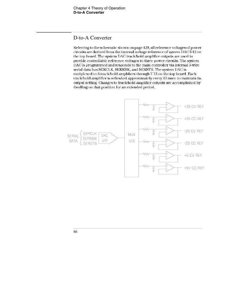
Chapter 4 Theory of Operation D-to-A Converter
D-to-A Converter
Referring to the schematic shown on page 129, all reference voltages of power
circuits are derived from the internal voltage reference of system DAC U12 on
the top board. The system DAC track/hold amplifier outputs are used to
provide controllable reference voltages to three power circuits. The system
DAC is programmed and responds to the main controller via internal 3-wire
serial data bus SERCLK, SERRBK, and SERSTB. The system DAC is
mutiplexed to 6 track/hold amplifiers through U13 on the top board. Each
track/hold amplifier is refreshed approximately every 13 msec to maintain its
output setting. Changes to track/hold amplifier outputs are accomplished by
dwelling on that position for an extended period.
86
Chapter 4 Theory of Operation A-to-D Converter
4
A-to-D Converter
Referring to the schematic shown on page 129, the analog-to-digital converter
(ADC) is used to change dc voltages into digital information. The circuitry
consists of an integrator amplifier (U6 and U8), current steering switch U5,
resistors (R5, R4, R15 and R16), voltage reference (U3A and U3B), ADC
controller U16, and residue ADC U17 on the top board.
The ADC method used by the Agilent E3631A is called multislope III.
Multislope III is a charge balancing continuously integrating analog-to-digital
converter. The input voltage continuously forces charge onto the integrator
capacitors C18 and C19 through R15 on the top board.
Switch U5 steers fixed positive or negative reference currents onto the
integrator capacitors to cancel, or balance the accumulated input charge. The
level shifted (R19 and R20 on the top board) output of the integrator is checked
every 2.66 μA by the U16 COMP input. Logic state machines in U16 control the
U5 current steering to continuously seek an approximate 2.5 V level on the
integrator amplifier output, FLASH. If the ADC input voltage ADC REF is
between ±15 V, the integrator output (FLASH) will remain within the 0 V to 5
V range of the U17 on-chip ADC. An input greater than +15 V may cause the
integrator output in U8 at pin 6 (U8-6) to saturate at about -15 V. An input less
than -15 V may cause U8 to saturate with an output of about +15 V. The U17
ADC input (FLASH) is clamped to 0 V or 5 V by R21 and CR3 to protect U17.
The integrator amplifier is formed by U6 and U8. Resistors R10 and R11 affect
the amplifier stability. Amplifier oscillation may occur if their values are
incorrect. Amplifier U6 improves the offset voltage characteristics of
integrator amplifier U8 on the top board.
Each analog-to-digital conversion occurs continuously. The ADC starts by
clearing the integrator slope count in U16. At the end of the integration period,
the slope count is latched. The slope count provides the most significant bits
of the input voltage conversion. The least significant bits are converted by the
on-chip ADC of U17.
87
Chapter 4 Theory of Operation Power Mesh and Control
Power Mesh and Control
Refer to the schematics shown on page 130 and page 131.
For the ±25V power mesh and control circuit, a preregulator is added ahead
of the series pass transistor to minimize the power dissipated in the series pass
transistor by controlling the dc level across the input filter capacitor,
depending on the output voltage.
To achieve this, tap switching is accomplished by a TRIAC and one bridge
diode and the TRIAC control circuit in each power circuit; Q10 and CR29 on
the top board for +25V power circuit, Q3 and CR7 on the top board for -25V
power circuit. By turning on or off the TRIAC, these circuits allow the input
capacitors (C54, C55, and C56 for +25V power circuit and C34, C35, and C36
for -25V power circuit) to charge to one of two discrete voltage levels,
depending on the output voltage required. When the TRIAC is not fired, the
bridge diode conducts and the low voltage of two discrete voltage levels is
developed across the input filter capacitors.
The TRIAC control circuit determines whether TRIAC is to be fired by
monitoring the output voltage and comparing this value against internally
derived reference levels.
The series pass transistor is part of a feedback loop which consists of the driver
and the Constant Voltage/Constant Current error amplifier. The feedback loop
provides "fine and fast" regulation of the output while the preregulator
feedback loop handles large, relatively slow, regulation demands.
The series pass transistor is made to alter its conduction to maintain a constant
output voltage or current. The voltage developed across the current sampling
resistors is the input to the constant current error amplifier. The constant
voltage error amplifier obtains its input by sampling the output voltage of the
supply. Any changes in output voltage or current are detected and amplified
by the constant voltage or constant current error circuit and applied to the
series pass transistor in the correct phase and amplitude to counteract the
change in output voltage or current.
88

Chapter 4 Theory of Operation Power Mesh and Control
4
Two error amplifiers are included in a CV/CC supply, one for controlling output
voltage, the other for controlling output current. Since the constant voltage
amplifier tends to achieve zero output impedance and alters the output current
whenever the load resistance changes, while the constant current amplifier
causes the output impedance to be infinite and changes the output voltage in
response to any load resistance change, it is obvious that the two amplifiers
can not operate simultaneously. For any given value of load resistance, the
power supply must act either as a constant voltage source or as a constant
current source - it can not be both; transfer between these two modes is
accomplished at a value of load resistance equal to the ratio of the output
voltage control setting to the output current control setting.
Full protection against any overload condition is inherent in the Constant
Voltage/Constant Current design principle since there is not any load condition
that can cause an output which lies outside the operating region. For either
constant voltage or constant current operation, the proper choice of front
panel voltage and current limit settings insures optimum protection for the
load device as well as full protection for the power supply.
The diodes connected across the output terminals in reverse polarity protect
the output electrolytic capacitor and the series pass transistors from the effects
of a reverse voltage applied across the output terminals.
The +6V power mesh and control circuits are similar to those of the ±25V power
circuits except that the the TRIAC preregulator is not used. The ac input, after
passing through power transformer, is rectified and filtered. By feedback
action, the series pass transistor alters its conduction to keep the regulated dc
output voltage constant.
The +6V and the ±25V power mesh and control circuits are isolated from each
other and the two outputs of the ±25V power mesh and control circuit share a
common output terminal.
89
Chapter 4 Theory of Operation Earth-Referenced Logic
Earth-Referenced Logic
Referring to the schematic shown on page 132, the earth referenced logic
circuits schematic provides all rear panel input/output capability.
Microprocessor U10 on the bottom board handles GPIB (IEEE-488) control
through bus interface chip U8 and bus receiver/driver chips U6 and U7 on the
bottom board. The RS-232 interface is also controlled through microprocessor
U10. RS-232 transceiver chip U12 on the bottom board provides the required
level shifting to approximate ±9 volt logic levels through on-chip charge-pump
power supplies using C11 and C12 on the bottom board. Communication
between the earth referenced logic interface circuits and the floating logic is
accomplished through an optically-isolated bi-directional serial interface.
Isolator U2 on the bottom board couples data from U10 to processor U17 on
the top board. Isolator U1 on the bottom board couples data from U17 on the
top board to microprocessor U10 on the bottom board.
Front Panel
Referring to the schematic shown on page 133, the front panel circuits consist
of vacuum fluorescent display control, display high voltage drivers, and
keyboard scanning. Communication between the front panel and floating logic
circuits is accomplished through a 4-wire bi-directional serial interface. The
main controller U17 can cause a hardware reset to front-panel controller by
signal IGFPRES. The front panel logic operates from -11.4 volts (logic 1) and -
16.4 volts (logic 0). The front panel logic high supply (-11.4 volts) is produced
by the -16.4 volts bias supply and the voltage regulator U2 on the front panel
board. The four serial communication signals are level shifted by the
comparator U8 from the floating logic 0 V to 5 V levels to the -16.4 V to -11.4 V
levels present on the front panel assembly. U6 acts as the serial shift register
interface for the front-panel controller U7 on the front panel board.
Display anode and grid voltages are +16.4 volts for an "on" segment and -16.4
volts for an "off" segment. The -10.2 V cathode bias for the display is provided
by filament winding center tap bias circuit VR3, R43, and C32 on the top board.
Keyboard scanning is accomplished through a conventional scanned row-
column key matrix. Keys are scanned by outputing data at front-panel
controller U7 port pins P0.0 through P0.3 to poll each key column for a key
press. Column read-back data are read by the microprocessor at port pins P1.0
through P1.3 for decoding and communication to the floating logic circuits.
90
5
5
Service
Service
This chapter discusses the procedures involved for returning a failed power
supply to Agilent Technologies for service or repair. Subjects covered include
the following:
• Operating Checklist, page 93
• Types of Service Available, page 94
• Repacking for Shipment, page 95
• Electrostatic Discharge (ESD) Precautions, page 96
• Surface Mount Repair, page 96
• To Replace the Power-Line Fuse, page 96
• Troubleshooting Hints, page 97
• Self-Test Procedures, page 99
92
Chapter 5 Service Operating Checklist
5
Operating Checklist
Before returning your power supply to Agilent Technologies for service or
repair check the following items:
Is the Power Supply Inoperative?
Verify that the ac power cord is connected to the power supply.
Verify that the front-panel power switch is depressed.
Verify that the power-line fuse is installed: Use the 2.5 AT, 250 V fuse for 100 or 115 Vac operation. Use the 2 AT, 250 V fuse for 230 Vac operation.
Verify the power-line voltage setting. See "To prepare the power supply for use" page 23.
Does the Power Supply Fail Self-Test? Verify that the correct power-line voltage is selected.
See "To prepare the power supply for use" page 23.
Remove all load connections to the power supply. Ensure that all terminal connections are removed while the self-test is
performed.
93

Chapter 5 Service Types of Service Available
Types of Service Available
If your power supply fails within one years of original purchase, Agilent
Technologies will repair or replace it free of charge. If your unit fails after your
one year warranty expires, Agilent will repair or replace it as a very competitive
price. Agilent will make the decision locally whether to repair or replace your
unit.
Standard Repair Service (worldwide)
Contact your nearest Agilent Technologies Service Center. They will arrange
to have your power supply repaired or replaced.
Express Exchange (U.S.A. only)You can receive a replacement Agilent E3631A via overnight shipment for low
downtime.
1 Call 1-800-258-5165 and ask for "Express Exchange."
• You will be asked for your shipping address and a credit card number to
guarantee return of your failed power supply.
• If you do not return your failed power supply within 45 days, your credit
card will be billed for a new Agilent E3631A.
• If you choose not to supply a credit card number, you will be asked to send
your failed unit to a designated Agilent Service Center. After the failed unit
is received, Agilent will send your replacement unit.
2 Agilent Technologies will immediately send a replacement Agilent E3631A to
you via overnight shipment.
• The replacement unit will have a different serial number than your failed
unit.
• If you can not accept a new serial number for the replacement unit, use the
Standard Repair Service option described above.
• If your failed unit was "in-warranty,'' your replacement unit continues the
original one year warranty period. You will not be billed for the replacement
unit as long as the failed unit is received by Agilent Technologies.
• If your one year warranty has expired, Agilent will bill you for the Agilent
E3631A exchange price - less than a new unit price. Agilent warrants
exchange units against defects for 90 days.
94
Chapter 5 Service Repacking for Shipment
5
Repacking for Shipment
For the Express Exchange Service described on the previous page, return your
failed Agilent E3631A to the designated Agilent Service Center using the
shipping carton of the exchange unit. A shipping label will be supplied. Agilent
will notify you when your failed unit has been received.
If the instrument is to be shipped to Agilent Technologies for service or repair,
be sure to:
• Attach a tag to the power supply identifying the owner and indicating the
required service or repair. Include the instrument model number and full
serial number.
• Place the power supply in its original container with appropriate packaging
material.
• Secure the container with strong tape or metal bands.
If the original shipping container is not available, place your unit in a container
which will ensure at least 4 inches of compressible packaging material around
all sides for the power supply. Use static-free packaging materials to avoid
additional damage to your unit.
Agilent Technologies suggests that you always insure shipments.
95

Chapter 5 Service Electrostatic Discharge (ESD) Precautions
Electrostatic Discharge (ESD) Precautions
Almost all electrical components can be damaged by electrostatic discharge
(ESD) during handling. Component damage can occur at electrostatic
discharge voltages as low as 50 volts.
The following guidelines will help prevent ESD damage when serving the
power supply or any electronic device.
• Disassemble instruments only in a static-free work area.
• Use a conductive work area to dissipate static charge.
• Use a conductive wrist strap to dissipate static charge accumulation.
• Minimize handling.
• Keep replacement parts in original static-free packaging.
• Remove all plastic, styrofoam, vinyl, paper, and other static-generating
materials from the immediate work area.
• Use only anti-static solder suckers.
Surface Mount Repair
Surface mount components should only be removed using soldering irons or
disordering stations expressly designed for surface mount components. Use
of conventional solder removal equipment will almost always result in
permanent damage to the printed circuit board and will void your Agilent
Technologies factory warranty.
To Replace the Power-Line Fuse
The power-line fuse is located within the power supply's fuse-holder assembly
on the rear panel (see page 24). For 100 or 115 Vac operation, you must use a
2.5 AT slow-blow fuse (Agilent part number 2110-0913). For 230 Vac operation,
you must use a 2 AT slow-blow fuse (Agilent part number 2110-0587).
96
Chapter 5 Service Troubleshooting Hints
5
Troubleshooting Hints
This section provides a brief check list of common failures. Before
troubleshooting or repairing the power supply, make sure that the failure is in
the instrument rather than any external connections. Also make sure that the
instrument is accurately calibrated. The power supply's circuits allow
troubleshooting and repair with basic equipment such as a digit multimeter
and a 100 MHz oscilloscope.
Unit is Inoperative
Verify that the ac power cord is connected to the power supply.
Verify that the front-panel power switch is depressed.
Verify that the power-line fuse is installed: Use the 2.5 AT, 250 V fuse for 100 or 115 Vac operation.. Use the 2 AT, 250 V fuse for 230 Vac operation..
Verify the power-line voltage setting. See "To prepare the power supply for use" page 23.
Unit Reports Errors 740 to 748
These errors may be produced if you accidentally turn off power the unit during
a calibration or while changing a non-volatile state of the instrument.
Recalibration or resetting the state should clear the error. If the error persists,
a hardware failure may have occurred.
Unit Fails Self-TestVerify that the correct power-line voltage setting is selected. Also, ensure that
all terminal connections are removed while the self-test is performed. Failure
of the DAC U12 on the top board will cause many self-test failures.
97
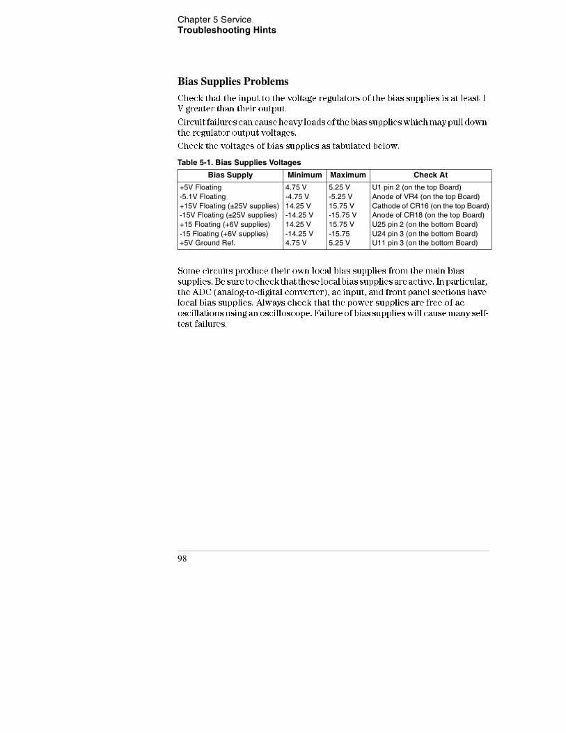
Chapter 5 Service Troubleshooting Hints
Bias Supplies Problems
Check that the input to the voltage regulators of the bias supplies is at least 1
V greater than their output.
Circuit failures can cause heavy loads of the bias supplies which may pull down
the regulator output voltages.
Check the voltages of bias supplies as tabulated below.
Table 5-1. Bias Supplies Voltages
Some circuits produce their own local bias supplies from the main bias
supplies. Be sure to check that these local bias supplies are active. In particular,
the ADC (analog-to-digital converter), ac input, and front panel sections have
local bias supplies. Always check that the power supplies are free of ac
oscillations using an oscilloscope. Failure of bias supplies will cause many self-
test failures.
Bias Supply Minimum Maximum Check At
+5V Floating-5.1V Floating+15V Floating (±25V supplies)-15V Floating (±25V supplies)+15 Floating (+6V supplies)-15 Floating (+6V supplies)+5V Ground Ref.
4.75 V-4.75 V14.25 V-14.25 V14.25 V-14.25 V4.75 V
5.25 V-5.25 V15.75 V-15.75 V15.75 V-15.755.25 V
U1 pin 2 (on the top Board)Anode of VR4 (on the top Board)Cathode of CR16 (on the top Board)Anode of CR18 (on the top Board)U25 pin 2 (on the bottom Board)U24 pin 3 (on the bottom Board)U11 pin 3 (on the bottom Board)
98
Chapter 5 Service Self-Test Procedures
5
Self-Test Procedures
Power-On Self-Test
Each time the power supply is powered on, a set of self-tests are performed.
These tests check that the minimum set of logic and measurement hardware
are functioning properly. The power-on self-test performs checks 601 through
604 and 624 through 634.
Complete Self-TestHold any front panel key except the "Error'' key for more than 5 seconds while
turning on the power to perform a complete self-test. The power supply beeps
when the test starts. The tests are performed in the order shown below.
601 Front Panel Does not respond The main controller U17 on the top board
attempts to establish serial communications with the front panel controller U7
on the front panel board. During this test, U7 turns on all display segments.
Communication must function in both directions for this test to pass. If this
error is detected during power-on self-test, the power supply will beep twice.
This error is only readable from the remote interface.
602 RAM read/write failed This test writes and reads a 55h and AAh checker
board pattern to each address of ram U15 on the top board. Any incorrect
readback will cause a test failure. This error is only readable from the remote
interface.
603 A/D sync stuck The main controller issues an A/D sync pulse to U17 and U16
on the top board to latch the value in the ADC slope counters. A failure is
detected when a sync interrupt is not recognized and subsequent time-out
occurs.
604 A/D slope convergence failed The input amplifier is configured to the
measure zero (MZ) state in the 10 V range. This test checks whether the ADC
integrator produces nominally the same number of positive and negative slope
decisions (±10%) during a 20 ms interval.
99

Chapter 5 Service Self-Test Procedures
605 Cannot calibrate rundown gain This test checks the nominal gain between
integrating ADC and the U17 on-chip ADC. This error is reported if the
procedure can not run to completion due to a hardware failure.
606 Rundown gain out of range This test checks the nominal gain between the
integrating ADC and the U17 on-chip ADC. The nominal gain is checked to
±10% tolerance.
607 Rundown too noisy This test checks the gain repeatability between the
integrating ADC and the U17 on-chip ADC. The gain test (606) is performed
eight times. Gain noise must be less that ±64 lsb's of the U17 on-chip ADC.
608 Serial configuration readback failed This test re-sends the last 3 byte
serial configuration data to all the serial path (SERDAT, SERBCK, SERCLK).
The data is then clocked back into U16 on the top board and compared against
the original 3 bytes sent. A failure occurs if the data do not match. This tests
checks the serial data path through U11 on the top board.
624 Unable to sense line frequency This test checks that the LSENCE logic
input U17 on the top board is togging. If no logic input detected, the power
supply will assume a 50 Hz line operation for all future measurements.
625 I/O processor did not respond This test checks that communications can
be established between U16 on the top board and U10 on the bottom board
through the optically isolated (U1 and U2 on the bottom board) serial data link.
Failure to establish communication in either direction will generate an error.
If this condition is detected at power-on self-test, the power supply will beep
and the error annunciator will be on.
626 I/O processor failed self-test This test causes the earth referenced
processor U10 on the bottom board to execute an internal, ram test. Failure
will generate an error.
630 Fan test failed This test checks if the fan current is flowing. If the current
is not detected at power-on self-test, the power supply will beep and the error
annunciator will be on.
631 System DAC test failed This test checks if the DAC hardware is functional.
The main controller U17 sends a reference voltage data to DAC and converts
the DAC output to digital data to see if the digital data is within a valid range.
100
Chapter 5 Service Self-Test Procedures
5
632 P6V hardware test failed This test checks the the status of voltage and
current error amplifiers for +6V power circuit. If both amplifiers are not
operational, the power supply will beep and the error annunciator will be on.
633 P25V hardware test failed This test checks the the status of voltage and
current error amplifiers for +25V power circuit. If both amplifiers are not
operational, the power supply will beep and the error annunciator will be on.
634 N25V hardware test failed This test checks the the status of voltage and
current error amplifiers for -25V power circuit. If both amplifiers are not
operational, the power supply will beep and the error annunciator will be on.
101

Chapter 5 Service Self-Test Procedures
102

6
Schematics
Schematics
This chapter contains component locator drawings, and schematics for the
power supply. The block diagram is also shown in chapter 4.
• E3631-60002 Component Locator, page 105
• E3631-60003 Component Locator, page 106
• E3631-60004 Component Locator, page 107
104
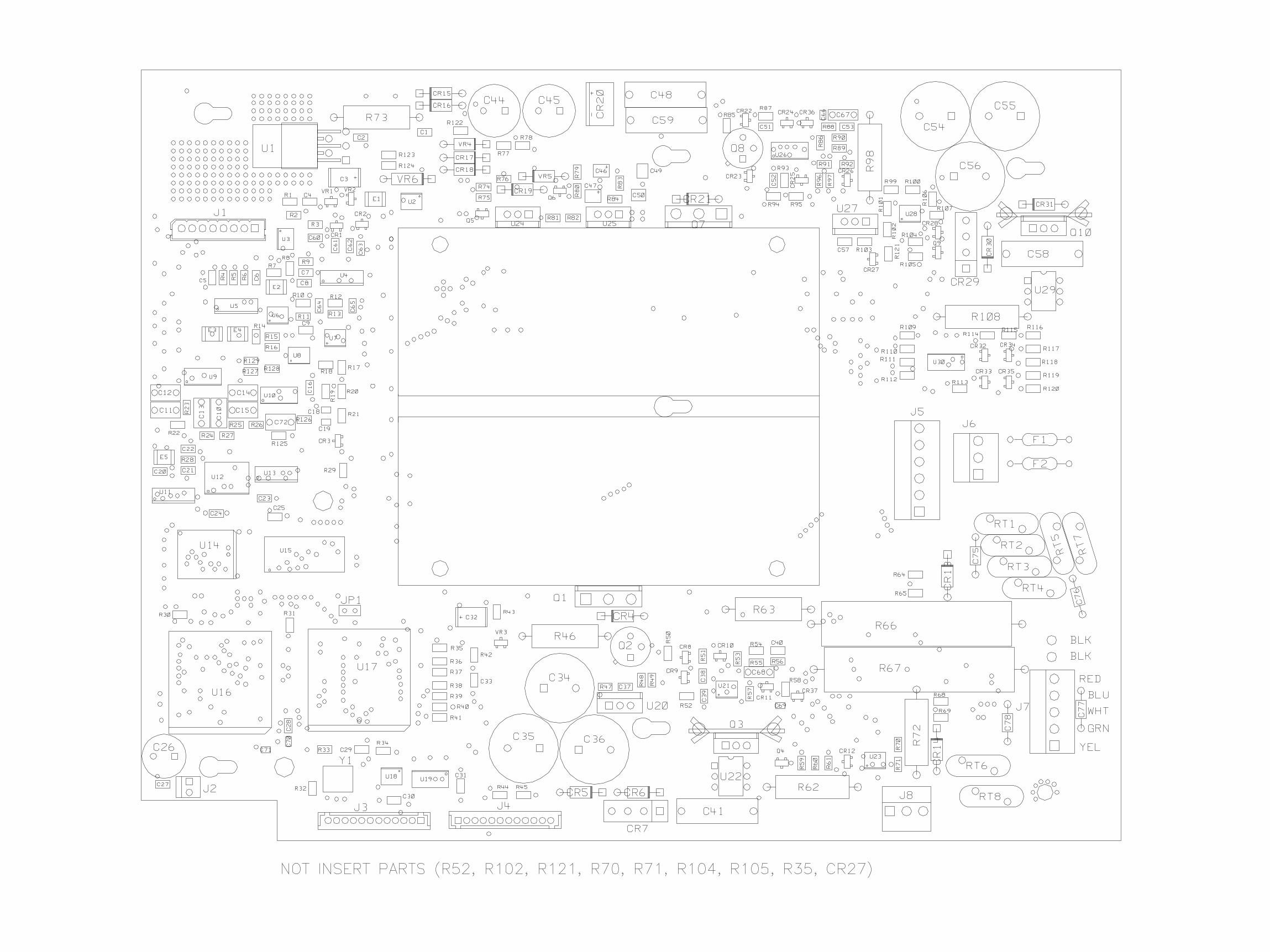
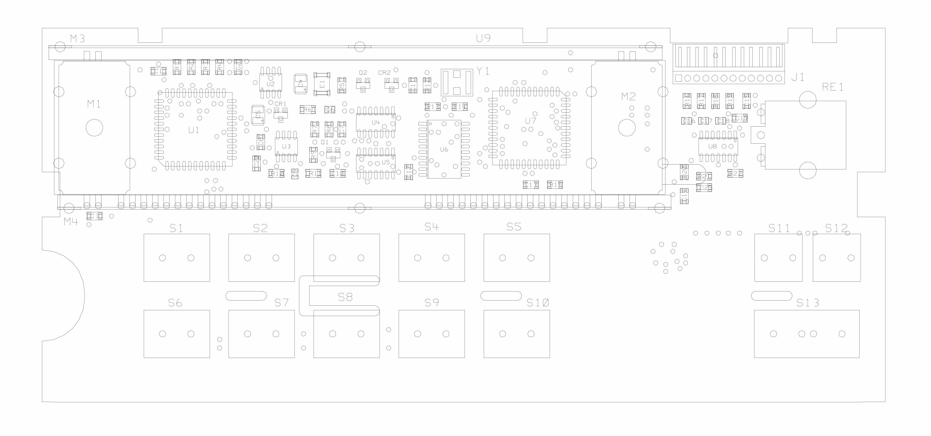
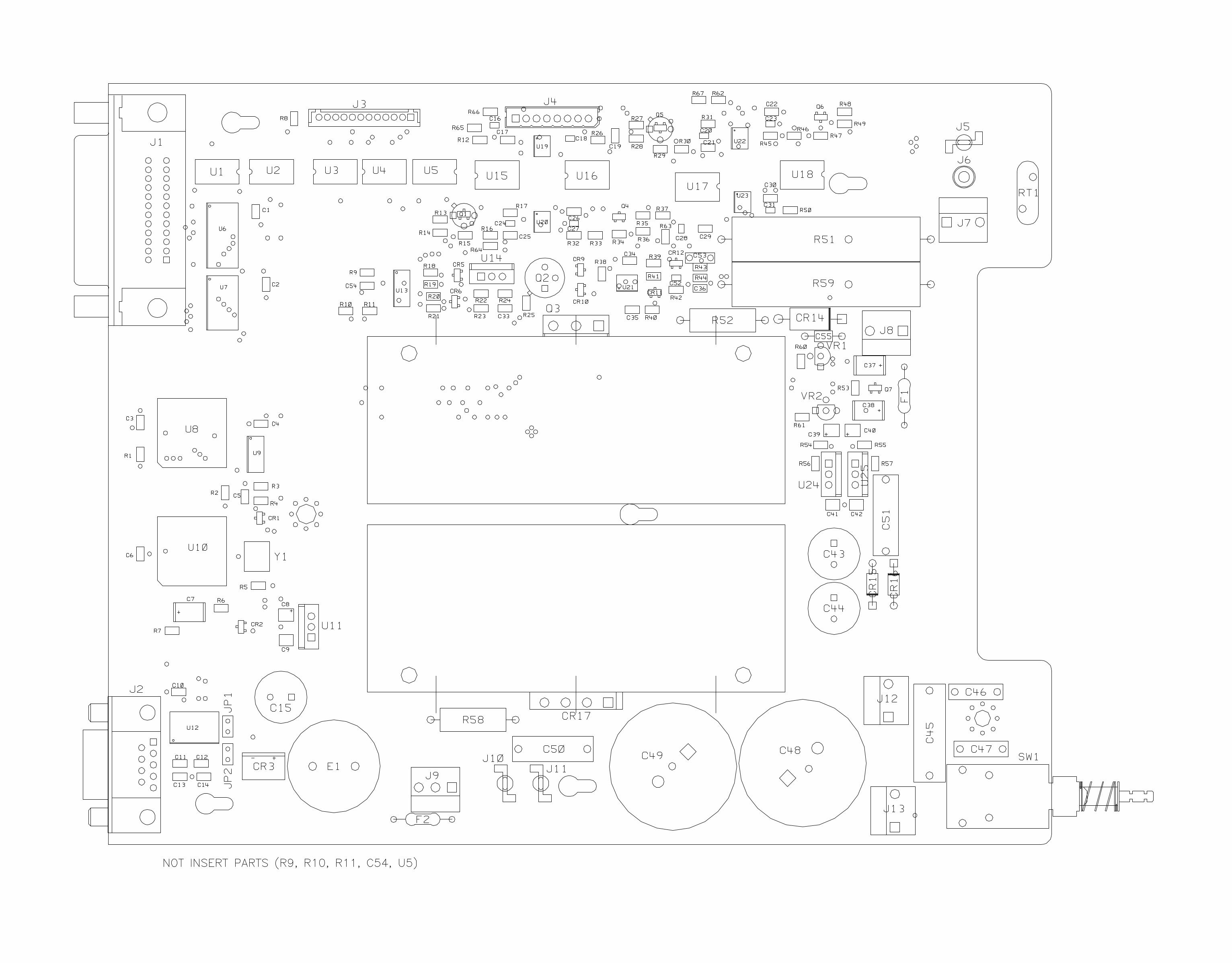
Copyright© 1995 - 2007Agilent TechnologiesAll Rights Reserved.
Printing History
Edition 7, October 2007
New editions are complete revisions of the manual. Update packages, which are issued between editions, may contain additional information and replace-ment pages which you merge into the manual. The dates on this page change only when a new edition is published.
Trademark Information
Windows, Windows 95, and Windows NT are registered trademarks of Microsoft Corp.
Certification
Agilent Technologies certifies that this product met its published specifica-tions at the time of ship-ment. Agilent further certifies that its calibration measurements are trace-able to the United States National Institute of Stan-dards and Technology (for-merly National Bureau of Standards), to the extent allowed by that organiza-tion’s calibration facility, and to the calibration facili-ties of other International Standards Organization members.
Warranty
This Agilent product is war-ranted against defects in materials and workmanship for a period of one year from date of shipment. Duration and conditions of warranty for this product may be superseded when the prod-uct is integrated into (becomes a part of) other Agilent products. During the warranty period, Agilent will, at its option, either repair or replace products which prove to be defective. The warranty period begins on the date of delivery or on the date of installation if installed by Agilent.
Warranty Service
For warranty service or repair, this product must be returned to a service facility designated by Agilent.
For products returned to Agilent for warranty service, the Buyer shall prepay ship-ping charges to Agilent and Agilent shall pay shipping charges to return the prod-uct to the Buyer. However, the Buyer shall pay all ship-ping charges, duties, and taxes for products returned to Agilent from another country.
Limitation of Warranty
The foregoing warranty shall not apply to defects resulting from improper or inadequate maintenance by the Buyer, Buyer-supplied products or interfacing, unauthorized modification or misuse, operation outside of the environmental specifi-cations for the product, or improper site preparation or maintenance.
The design and implementa-tion of any circuit on this product is the sole responsi-bility of the Buyer. Agilent does not warrant the Buyer’s circuitry or malfunctions of Agilent products that result from the Buyer’s circuitry. In addition, Agilent does not warrant any damage that occurs as a result of the Buyer’s circuit or any defects that result from Buyer-supplied products.
To the extent allowed by local law, Agilent makes no other warranty, expressed or implied, whether written or oral with respect to this prod-uct and specifically dis-claims any implied warranty or condition of merchantability, fitness for a particular purpose or satisfactory quality.
For transactions in Austra-
lia and New Zealand: The warranty terms contained in this statement, except to the extent lawfully permitted, do not exclude, restrict, or modify and are in addition to the mandatory statutory rights applicable to the sale of this product.
Exclusive Remedies
To the extent allowed by local law, the remedies pro-vided herein are the Buyer’s sole and exclusive remedies. Agilent shall not be liable for any direct, indirect, special, incidental, or consequential damages (including lost profit or data), whether based on warranty, contract, tort, or any other legal the-ory.
Notice
The information contained in this document is subject to change without notice.
To the extent allowed by local law, Agilent makes no warranty of any kind with regard to this material, including, but not limited to, the implied warranties of merchantability and fitness for a particular purpose.
To the extent allowed by local law, Agilent shall not be liable for errors con-tained herein or for inciden-tal or consequential damages in connection with the furnishing, performance, or use of this material. No part of this document may be photocopied, repro-duced, or translated to another language without the prior written consent of Agilent.
Restricted Rights
The Software and Documen-tation have been developed entirely at private expense. They are delivered and licensed as “commercial computer software” as defined in DFARS 252.227-7013 (Oct 1988), DFARS 252.211-7015 (May 1991), or DFARS 252.227-7014 (Jun 1995), as a “commercial item” as defined in FAR 2.101(a), or as “restricted computer software” as defined in FAR 52.227-19 (Jun 1987) (or any equiva-lent agency regulation or contract clause), whichever is applicable. You have only those rights provided for such Software and Docu-mentation by the applicable FAR or DFARS clause or the Agilent standard software agreement for the product involved.
Safety Information
Do not install substitute parts or perform any unauthorized modification to the product. Return the product to an HP Sales and Service Office for service and repair to ensure that safety features are main-tained.
Safety Symbols
WarningCalls attention to a proce-dure, practice, or condition, that could possibly cause bodily injury or death.
CautionCalls attention to a proce-dure, practice, or condition that could possibly cause damage to equipment or per-manent loss of data.
Earth ground symbol.
Chassis ground symbol.
Refer to the manual for specific Warning or Caution information to avoid per-sonal injury or equipment damage.Hazardous voltages may be present.
Warning
No operator serviceable parts inside. Refer servicing to service-trained personnel.
Warning
For continued protection against fire, replace the line fuse only with a fuse of the specified type and rating.
!
Manual Part Number: E3631-90011 Printed: October 2007 Edition 7Printed in Malaysia
© Agilent Technologies, Inc. 1995-2007
Printed in MalaysiaSeventh Edition, October 2007
E3631-90011
www.agilent.com
Agilent Technologies
Contact usTo obtain service, warranty or technical support assistance, contact us at the following phone numbers:
United States:(tel) 800 829 4444 (fax) 800 829 4433Canada:(tel) 877 894 4414 (fax) 800 746 4866China:(tel) 800 810 0189 (fax) 800 820 2816Europe:(tel) 31 20 547 2111Japan:(tel) (81) 426 56 7832 (fax) (81) 426 56 7840Korea:(tel) (080) 769 0800 (fax) (080) 769 0900Latin America:(tel) (305) 269 7500Taiwan:(tel) 0800 047 866 (fax) 0800 286 331Other Asia Pacific Countries:(tel) (65) 6375 8100 (fax) (65) 6755 0042
Or visit Agilent worlwide Web at:www.agilent.com/find/assist
Product specifications and descriptions in this document are subject to change without notice.