Agilent 1260 Infinity Bio-inert Quaternary LC - System Manual
94
Agilent Technologies Agilent 1260 Infinity Bio-inert Quaternary LC System manual
Transcript of Agilent 1260 Infinity Bio-inert Quaternary LC - System Manual

Agilent Technologies
Agilent 1260 Infinity Bio-inert Quaternary LC
System manual

Notices© Agilent Technologies, Inc. 2011-2012
No part of this manual may be reproduced in any form or by any means (including elec-tronic storage and retrieval or translation into a foreign language) without prior agree-ment and written consent from Agilent Technologies, Inc. as governed by United States and international copyright laws.
Manual Part NumberG5611-90301
Edition11/2012
Printed in Germany
Agilent TechnologiesHewlett-Packard-Strasse 8 76337 Waldbronn
This product may be used as a com-ponent of an in vitro diagnostic sys-tem if the system is registered with the appropriate authorities and com-plies with the relevant regulations. Otherwise, it is intended only for gen-eral laboratory use.
Warranty
The material contained in this docu-ment is provided “as is,” and is sub-ject to being changed, without notice, in future editions. Further, to the max-imum extent permitted by applicable law, Agilent disclaims all warranties, either express or implied, with regard to this manual and any information contained herein, including but not limited to the implied warranties of merchantability and fitness for a par-ticular purpose. Agilent shall not be liable for errors or for incidental or consequential damages in connection with the furnishing, use, or perfor-mance of this document or of any information contained herein. Should Agilent and the user have a separate written agreement with warranty terms covering the material in this document that conflict with these terms, the warranty terms in the sep-arate agreement shall control.
Technology Licenses The hardware and/or software described in this document are furnished under a license and may be used or copied only in accor-dance with the terms of such license.
Restricted Rights LegendIf software is for use in the performance of a U.S. Government prime contract or subcon-tract, Software is delivered and licensed as “Commercial computer software” as defined in DFAR 252.227-7014 (June 1995), or as a “commercial item” as defined in FAR 2.101(a) or as “Restricted computer soft-ware” as defined in FAR 52.227-19 (June 1987) or any equivalent agency regulation or contract clause. Use, duplication or dis-closure of Software is subject to Agilent Technologies’ standard commercial license terms, and non-DOD Departments and Agencies of the U.S. Government will
receive no greater than Restricted Rights as defined in FAR 52.227-19(c)(1-2) (June 1987). U.S. Government users will receive no greater than Limited Rights as defined in FAR 52.227-14 (June 1987) or DFAR 252.227-7015 (b)(2) (November 1995), as applicable in any technical data.
Safety Notices
CAUTION
A CAUTION notice denotes a hazard. It calls attention to an operating procedure, practice, or the like that, if not correctly per-formed or adhered to, could result in damage to the product or loss of important data. Do not proceed beyond a CAUTION notice until the indicated condi-tions are fully understood and met.
WARNING
A WARNING notice denotes a hazard. It calls attention to an operating procedure, practice, or the like that, if not correctly performed or adhered to, could result in personal injury or death. Do not proceed beyond a WARNING notice until the indi-cated conditions are fully under-stood and met.
Bio-inert Quaternary LC
In This Book
In This Book
This manual describes the Agilent 1260 Infinity Bio-inert System
For detailed information on bio-inert modules, see the separate manuals.
1 Introduction
This chapter gives an introduction to the Agilent 1260 Infinity Bio-inert Quaternary LC and explains underlying concepts and features of the system.
2 System Setup and Installation
This chapter includes information on software installation, stack configurations and how to prepare the system for operation.
3 Quick Start Guide
This chapter provides information on data acquisition and data analysis with the Agilent 1260 Infinity Bio-inert Quaternary LC.
4 Typical Bio-inert LC Applications
This chapter gives an overview on typical Bio-inert LC application examples in protein characterization.
5 Specifications
This chapter provides information about specifications of the 1260 Infinity Bio-inert Quaternary LC system.
6 Appendix
This chapter provides addition information on safety, legal and web
Bio-inert Quaternary LC 3

Contents
Contents
1 Introduction 7
Concepts of the 1260 Infinity Bio-inert Quaternary LC System 8System Properties 9System Components 10Bio-inert Materials 12Optimizing the Stack Configuration 14Bio-inert Quaternary pump (G5611A) 19Autosampler (G5667A) 22Bio-inert Manual Injector (G5628A) 24Thermostatted column compartment (G1316C) with Bio-inert heat exchangers 25Bio-inert Flow Cells for Detectors 27Fraction Collector (G5664A) 29
2 System Setup and Installation 31
Installing Software 32Installing the Modules 33
3 Quick Start Guide 47
Preparing the System 48Setting Up the Method 54
4 Typical Bio-inert LC Applications 57
Characterization of bio-therapeutics 58Application Examples 59
5 Specifications 63
Performance Specifications 64Solvent Information 71
4 Bio-inert Quaternary LC

Contents
6 Appendix 75
Safety 76The Waste Electrical and Electronic Equipment Directive 79Lithium Batteries Information 80Radio Interference 81Sound Emission 82UV Radiation 83Declaration of Conformity for HOX2 Filter 84Installation of Stainless Steel Cladded PEEK Capillaries 85Agilent Technologies on Internet 91
Bio-inert Quaternary LC 5

Contents
6 Bio-inert Quaternary LC

Bio-inert Quaternary LC
1Introduction
Concepts of the 1260 Infinity Bio-inert Quaternary LC System 8
System Properties 9
System Components 10
Bio-inert Materials 12
Optimizing the Stack Configuration 14
One Stack Configuration 15
Two Stack Configuration 17
Bio-inert Quaternary pump (G5611A) 19
Hydraulic Path 21
Autosampler (G5667A) 22
Bio-inert Manual Injector (G5628A) 24
Thermostatted column compartment (G1316C) with Bio-inert heat exchangers 25
Bio-inert Flow Cells for Detectors 27
Fraction Collector (G5664A) 29
This chapter gives an introduction to the Agilent 1260 Infinity Bio-inert Quaternary LC and explains underlying concepts and features of the system.
7Agilent Technologies

1 IntroductionConcepts of the 1260 Infinity Bio-inert Quaternary LC System
Concepts of the 1260 Infinity Bio-inert Quaternary LC System
The Agilent 1260 Infinity Bio-inert Quaternary LC System can withstand harsh conditions for bio-analytic and biopurification applications while maintaining the performance of a modern UHPLC instrument. This is possible through the careful design of all components that are in contact with mobile phase and sample. Problems often associated with large bio-molecules are non-specific surface interactions, analyte discrimination and metal ion release which can cause decreased column lifetime, peak-tailing or lack of resolution. In addition, high salt concentration and extreme pH values cause corrosion and decrease robustness and instrument uptime.
The Agilent 1260 Infinity Bio-inert Quaternary LC System is based on the industry-proven Agilent 1200 Infinity Quaternary LC system with the entire flow path being biologically inert. All solvent lines in the pump are made of titanium, making them completely resistant to corrosion. All capillaries and fittings throughout the autosampler, column compartment and detectors are completely metal-free so that bio-molecules in the sample come in contact only with ceramics or PEEK. This minimizes secondary interactions of proteins and peptides with metallic surfaces, which could cause peak tailing, low recovery and decreased column lifetime.
8 Bio-inert Quaternary LC

Introduction 1System Properties
System Properties
• Titanium/gold pump solvent lines with quaternary solvent capability for online buffer mixing from up to four solvents at 600 bar
• Flow rates up to 10 mL/min in gradient operation and bio-inert fraction collection for automated bio-purification and semi-prep work with larger column dimensions (3 mm, 4.6 mm, 7.2 mm, 10 mm ID columns)
• Integrated micro vacuum degasser offers high degassing efficiency for trouble-free operation and highest performance, and completely eliminates the need for helium sparging
• Bio-compatible valves for solvent selection or column switching for easy method development (2-pos/6-port, 4-column selector, 12-pos/13-port valve)
• Bio-inert flow cells for MWD, DAD and FLD
• Mix-and-match compatibility with existing Agilent systems for full flexibility to meet future requirements
• Direct front access for quick exchange of maintenance parts
• Fast identification of problems by self-diagnostics, built-in log books and preprogrammed test methods
• Widest pH compatibility (pH 1 – 13)
• High corrosion resistance
Bio-inert Quaternary LC 9
1 IntroductionSystem Components
System Components
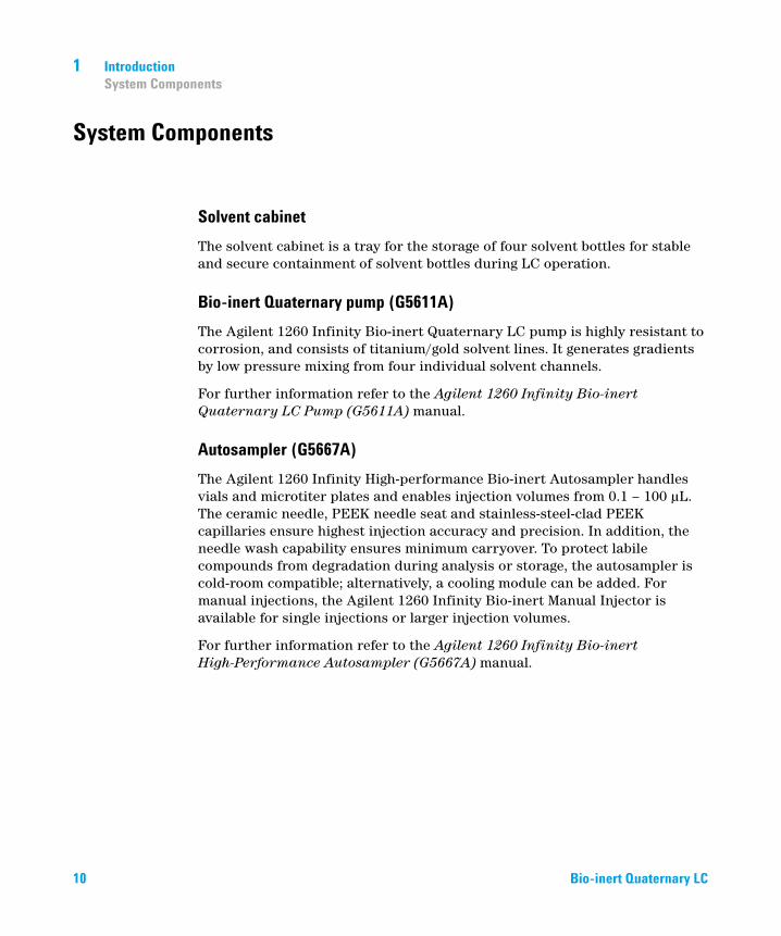
Solvent cabinet
The solvent cabinet is a tray for the storage of four solvent bottles for stable and secure containment of solvent bottles during LC operation.
Bio-inert Quaternary pump (G5611A)
The Agilent 1260 Infinity Bio-inert Quaternary LC pump is highly resistant to corrosion, and consists of titanium/gold solvent lines. It generates gradients by low pressure mixing from four individual solvent channels.
For further information refer to the Agilent 1260 Infinity Bio-inert Quaternary LC Pump (G5611A) manual.
Autosampler (G5667A)
The Agilent 1260 Infinity High-performance Bio-inert Autosampler handles vials and microtiter plates and enables injection volumes from 0.1 – 100 μL. The ceramic needle, PEEK needle seat and stainless-steel-clad PEEK capillaries ensure highest injection accuracy and precision. In addition, the needle wash capability ensures minimum carryover. To protect labile compounds from degradation during analysis or storage, the autosampler is cold-room compatible; alternatively, a cooling module can be added. For manual injections, the Agilent 1260 Infinity Bio-inert Manual Injector is available for single injections or larger injection volumes.
For further information refer to the Agilent 1260 Infinity Bio-inert High-Performance Autosampler (G5667A) manual.
10 Bio-inert Quaternary LC

Introduction 1System Components
Thermostatted column compartment (G1316C)
The Agilent 1290 Infinity Column Compartment includes bio-inert heating elements to pre-heat the solvent before it reaches the column. The column compartment houses either four short columns or two columns up to 30 cm in length. Agilent Quick- Change valves are available for more complex workflows such as column switching, column screening or method development.
For further information refer to the Agilent 1290 Infinity Thermostatted Column Compartment (G1316C) manual.
Diode array, multiple wavelength detector or other detector choices (G1315C/D, G4212A/B, G1321B)
Agilent offers a variety of detection options to address the requirements of protein research applications or of assays to assess the integrity of bio-therapeutic compounds. Bio-inert flow cells are available for MWD, DAD and FLD.
For further information refer to the Agilent 1260 Infinity Diode Array and Multiple Wavelength Detector, Agilent 1200 Infinity Series Diode Array Detectors (G4212A/B) and Agilent 1260 Infinity Fluorescence Detector (G1321B) manual.
Fraction Collector with Cooling Option (G5664A)
The Agilent 1260 Infinity Bio-inert Fraction Collector provides patented fraction delay calibration and time- or peak-triggered fraction collection for best recovery and purity of proteins.
For further information refer to the Agilent 1260 Infinity Bio-inert Analytical-scale Fraction Collector (G5664A) manual.
Bio-inert Quaternary LC 11

1 IntroductionBio-inert Materials
Bio-inert Materials
For the Agilent 1260 Infinity Bio-inert LC system, Agilent Technologies uses highest quality materials in the flow path (also referred to as wetted parts), which are widely accepted by life scientists, as they are known for optimum inertness to biological samples and ensure best compatibility with common samples and solvents over a wide pH range. Explicitly, the complete flow path is free of stainless steel and free of other alloys containing metals such as iron, nickel, cobalt, chromium, molybdenum or copper, which can interfere with biological samples. The flow downstream of the sample introduction contains no metals whatsoever.
Max-Light Cartridge Cell Bio-inert ( 60 mm, V(s) 4.0 μL) (G5615-60017) and Max-Light Cartridge Cell Bio-inert ( 10 mm, V(s) 1.0 μL) (G5615-60018) offer highest sensitivity for bio-inert reverse phase applications. Please note that at low salt SEC or ion exchange chromatography potentially peak tailing might occur, and therefore for these applications the universal Bio-inert DAD (G1315C or D) or MWD (G1365C or D) is recommended.
Table 1 Bio-inert materials used in Agilent 1260 Infinity Systems
Module Materials
Agilent 1260 Infinity Bio-inert Quaternary Pump (G5611A)
Titanium, gold, platinum-iridium, ceramic, ruby, PTFE, PEEK
Agilent 1260 Infinity Bio-inert High-Performance Autosampler(G5667A)
Upstream of sample introduction:• Titanium, gold, PTFE, PEEK, ceramic
Downstream of sample introduction:• PEEK, ceramic
Agilent 1260 Infinity Bio-inert Manual Injector(G5628A)
PEEK, ceramic
Agilent 1260 Infinity Bio-inert Analytical Fraction Collector(G5664A)
PEEK, ceramic, PTFE
12 Bio-inert Quaternary LC

Introduction 1Bio-inert Materials
Bio-inert Flow Cells:
Standard flow cell bio-inert, 10 mm, 13 µL, 120 bar ( 12 MPa) for MWD/DAD, includes Capillary Kit Flow Cells BIO (p/n G5615-68755) (G5615-60022) (for Agilent 1260 Infinity Diode Array Detectors DAD G1315C/D)
PEEK, ceramic, sapphire, PTFE
Max-Light Cartridge Cell Bio-inert ( 10 mm, V(s) 1.0 µL) (G5615-60018) andMax-Light Cartridge Cell Bio-inert ( 60 mm, V(s) 4.0 µL) (G5615-60017) (for Agilent 1200 Infinity Series Diode Array Detectors DAD G4212A/B)
PEEK, fused silica
Bio-inert flow cell, 8 µL, 20 bar (pH 1–12) includes Capillary Kit Flow Cells BIO (p/n G5615-68755) (G5615-60005) (for Agilent 1260 Infinity Fluorescence Detector FLD G1321B)
PEEK, fused silica, PTFE
Bio-inert heat-exchanger G5616-60050(for Agilent 1290 Infinity Thermostatted Column Compartment G1316C)
PEEK (steel-cladded)
Bio-inert Valve heads G4235A, G5631A, G5639A: PEEK, ceramic (Al2O3 based)
Bio-inert Connection capillaries Upstream of sample introduction:• Titanium
Downstream of sample introduction:• Agilent uses stainless-steel-cladded
PEEK capillaries, which keep the flow path free of steel and provide pressure stability to more than 600 bar.
Table 1 Bio-inert materials used in Agilent 1260 Infinity Systems
Module Materials
NOTE To ensure optimum bio-compatibility of your Agilent 1260 Infinity Bio-inert LC system, do not include non-inert standard modules or parts to the flow path. Do not use any parts that are not labeled as Agilent “Bio-inert”. For solvent compatibility of these materials, see “Solvent information for parts of the 1260 Infinity Bio-inert LC system” on page 71.
Bio-inert Quaternary LC 13

1 IntroductionOptimizing the Stack Configuration
Optimizing the Stack Configuration
You can ensure optimum performance by installing the system in one of the following configurations. These configurations optimize the system flow path, ensuring minimum delay volume.
14 Bio-inert Quaternary LC

Introduction 1Optimizing the Stack Configuration
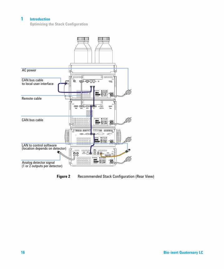
One Stack Configuration
Install the modules of the Agilent 1260 Infinity Bio-inert LC System in the configuration shown in Figure 1 on page 15 and Figure 2 on page 16. This configuration optimizes the flow path for minimum delay volume and minimizes the bench space required.
Figure 1 Recommended Stack Configuration (Front View)
Bio-inert Quaternary LC 15
1 IntroductionOptimizing the Stack Configuration
Figure 2 Recommended Stack Configuration (Rear View)
16 Bio-inert Quaternary LC

Introduction 1Optimizing the Stack Configuration
Two Stack Configuration
To avoid excessive height of the stack, for example, when the autosampler thermostat or fraction collector is added to the system we recommend that you form two stacks. A slightly longer capillary is required between the pump and autosampler, see Figure 3 on page 17 and Figure 4 on page 18.
Figure 3 Two stack configuration (front view)
Bio-inert Quaternary LC 17

1 IntroductionOptimizing the Stack Configuration
Figure 4 Two stack configuration (rear view)
18 Bio-inert Quaternary LC

Introduction 1Bio-inert Quaternary pump (G5611A)
Bio-inert Quaternary pump (G5611A)
Figure 5 Overview of the bio-inert quaternary pump
The Agilent 1260 Infinity Bio-inert Quaternary LC pump is highly resistant to corrosion and provides a titanium/gold solvent flow path. It generates gradients by low pressure mixing from four individual solvent channels. It is based on a two-channel, dual-plunger in-series design which comprises all essential functions that a solvent delivery system has to fulfill. Metering of solvent and delivery to the high-pressure side are performed by one pump assembly which can generate pressure up to 600 bar and deliver flow rates up to 10 mL/min. The pump can also be run in Emulation Mode (400 bar) for compatibility with classic modules.
Bio-inert Quaternary LC 19
1 IntroductionBio-inert Quaternary pump (G5611A)
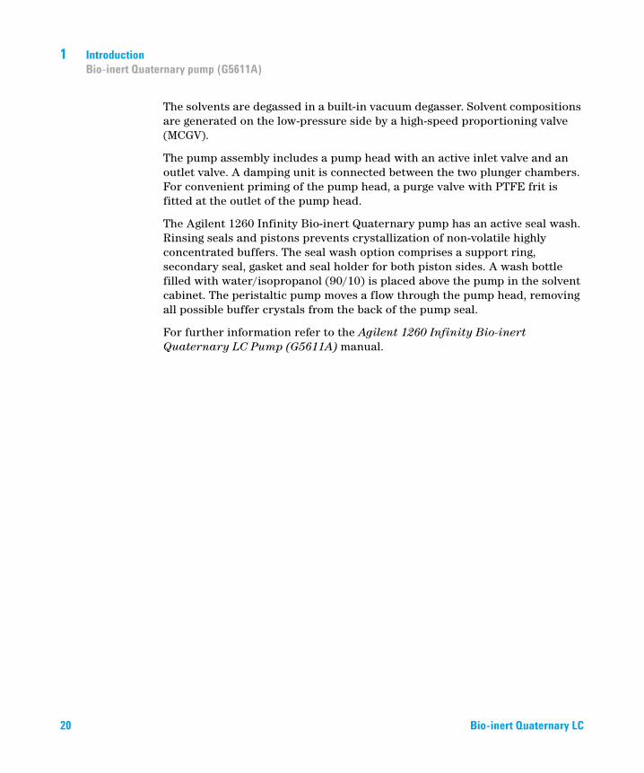
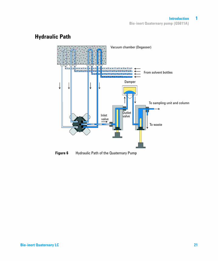
The solvents are degassed in a built-in vacuum degasser. Solvent compositions are generated on the low-pressure side by a high-speed proportioning valve (MCGV).
The pump assembly includes a pump head with an active inlet valve and an outlet valve. A damping unit is connected between the two plunger chambers. For convenient priming of the pump head, a purge valve with PTFE frit is fitted at the outlet of the pump head.
The Agilent 1260 Infinity Bio-inert Quaternary pump has an active seal wash. Rinsing seals and pistons prevents crystallization of non-volatile highly concentrated buffers. The seal wash option comprises a support ring, secondary seal, gasket and seal holder for both piston sides. A wash bottle filled with water/isopropanol (90/10) is placed above the pump in the solvent cabinet. The peristaltic pump moves a flow through the pump head, removing all possible buffer crystals from the back of the pump seal.
For further information refer to the Agilent 1260 Infinity Bio-inert Quaternary LC Pump (G5611A) manual.
20 Bio-inert Quaternary LC
Introduction 1Bio-inert Quaternary pump (G5611A)
Hydraulic Path
Figure 6 Hydraulic Path of the Quaternary Pump
Bio-inert Quaternary LC 21

1 IntroductionAutosampler (G5667A)
Autosampler (G5667A)
Figure 7 Autosampler (G5667A)
22 Bio-inert Quaternary LC

Introduction 1Autosampler (G5667A)
The Agilent 1260 Infinity High-performance Bio-inert Autosampler handles vials and microtiter plates. It injects volumes from 0.1 – 100 μL and is extendable to 900 μL.
The ceramic needle, PEEK needle seat and wash, and stainless-steel-clad PEEK capillaries ensure the highest injection accuracy and precision with minimum carryover. To protect labile compounds from degradation during analysis or storage, the autosampler is cold-room compatible; alternatively, you can add a cooling module.
The Agilent 1260 Infinity High-performance Bio-inert Autosampler is based on the High Performance Autosampler (G1367E). For further information refer to the Agilent 1260 Infinity Bio-inert High-Performance Autosampler (G5667A) manual.
Bio-inert Quaternary LC 23

1 IntroductionBio-inert Manual Injector (G5628A)
Bio-inert Manual Injector (G5628A)
The Agilent 1260 Bio-inert Manual Injector can be used for manual operation or use of large injection volumes. It offers a standard injection volume of 20 μL (optional 5 μL to 5 mL) and ensures highest injection accuracy.
Agilent 1260 Bio-inert Manual Injector uses a Bio-inert 6-port sample injection valve (5067-4158). Sample is loaded into the external 20 μL sample loop through the injection port at the front of the valve. The valve has a PEEK™ injection seal. A make-before-break passage in the stator ensures that the flow is not interrupted when the valve is switched between the INJECT and LOAD positions, and back again.
Agilent 1260 Bio-inert Manual Injector is based on the Manual Injector (G1328C). For further information refer to the Agilent 1260 Infinity Bio-inert Manual Injector Manual (G5628A).
24 Bio-inert Quaternary LC

Introduction 1Thermostatted column compartment (G1316C) with Bio-inert heat exchangers
Thermostatted column compartment (G1316C) with Bio-inert heat exchangers
Figure 8 Thermostatted column compartment with column identification system
Bio-inert Quaternary LC 25
1 IntroductionThermostatted column compartment (G1316C) with Bio-inert heat exchangers
The Agilent 1290 Infinity Thermostatted Column Compartment is a stackable temperature-controlled column compartment for LC. It is used for heating and cooling to meet extreme requirements of retention time reproducibility.
The main features are:
• Bio-inert heating elements — peltier heating and cooling from 10 °C below ambient up to 80 °C with high heating and cooling speeds for maximum application flexibility and stability.
• Holds up to three 30 cm columns (without heating elements) and optimized design gives minimum dead volumes and maximum efficiency.
• Up to 6 additional bio-inert heat exchangers contribute only 9 μL.
• Electronic column-identification module as standard for GLP documentation of column type and major column parameters.
• Optional high-quality Rheodyne® column switching valves with ceramic stator-face assemblies for prolonged lifetime.
For specifications, see “Specifications – Bio-inert LC capillaries, connectors, detector flow cells, solvent heating elements and valves” on page 68.
26 Bio-inert Quaternary LC

Introduction 1Bio-inert Flow Cells for Detectors
Bio-inert Flow Cells for Detectors
Diode-Array Detector (DAD)
1 Agilent 1260 Infinity DAD VL+ (G1315C)
This detector with robust Bio-inert flow cell (pH 1 – 14) is the standard detector for universal Bio-molecule applications. It features 80 Hz detection rates, RFID tags and a wide pH range for highest robustness.
Figure 9 Overview of bio-inert flow cell (G1315C)
Bio-inert Quaternary LC 27

1 IntroductionBio-inert Flow Cells for Detectors
2 Agilent 1260 Infinity DAD (G4212B)
This detector is highly sensitive for applications such as anion exchange and SEC analysis at pH < 8. Two Bio-inert flow cells are available: a 10 mm and a 60 mm cell. Both have the same cartridge design as the non-Bio-inert flow cells for this detector.
• Higher sensitivity for conventional LC, as well as ultra fast applications, by using next-generation optical design.
• Increased sensitivity with 60 mm Max-Light cartridge flow cell.
• Optimized cell geometry for less peak dispersion in narrow-bore applications.
• RFID tracking technology is used for the UV-lamp and the Max-Light cartridge flow cells.
• Easy exchange of flow cell by cartridge design.
For specifications of flow cells, see “Specifications – Bio-inert LC capillaries, connectors, detector flow cells, solvent heating elements and valves” on page 68.
Other Detectors
Bio-inert flow cells for Multiple Wavelength Detector (G1365C) and Fluorescence Detector (G1321B) are available. Materials Used are described in detail in “Specifications – Bio-inert LC capillaries, connectors, detector flow cells, solvent heating elements and valves” on page 68.
28 Bio-inert Quaternary LC

Introduction 1Fraction Collector (G5664A)
Fraction Collector (G5664A)
Figure 10 Overview of fraction collector (G5664A)
Bio-inert Quaternary LC 29

1 IntroductionFraction Collector (G5664A)
Figure 11 Injection of delay calibration sample
The Agilent 1260 Infinity Bio-inert Fraction Collector provides patented fraction delay calibration and time- or peak-triggered fraction collection for best recovery and purity of proteins. A wide range of collection vessels, such as vials, microtiter plates or custom vessels give highest flexibility. Flow rates up to 10 mL/min enable separations with large diameter columns.
30 Bio-inert Quaternary LC

Bio-inert Quaternary LC
2System Setup and Installation
Installing Software 32
Installing the Modules 33
Capillary and Tubing Connections in Flow Path 33
Installing Capillaries 36
Priming the System 41
Storage of the system 45
This chapter includes information on software installation, stack configurations and how to prepare the system for operation.
31Agilent Technologies

2 System Setup and InstallationInstalling Software
Installing Software
Installing the Software Controller and Data System
For details of installation procedures for the software, refer to the detector manual and the software manuals.
Installing the Agilent Lab Advisor Software
For details of installation procedures for the Agilent Lab Advisor software, refer to the software documentation on the Lab Advisor DVD.
Agilent Lab Advisor replaces and extends the diagnostic functions that were formerly available only in the ChemStation software.
Agilent Lab Advisor is a Windows®-based application that continuously monitors instruments in the lab in real time and increases productivity through automatic notification of maintenance and service needs with the use of advanced counters. This allows a problem to be fixed before it impacts results. The software includes an extensive suite of user information and documentation, a set of calculators and tools to help set up, calibrate, and maintain your instrument, and tests and diagnostic routines to verify proper performance. Agilent Lab Advisor also provides feedback and solutions for any instrument errors that may arise. The software will work with or without Agilent data systems.
The software monitors:
• LC module status
• Early Maintenance Feedback (to determine the need for upgrade or replacement)
In addition, the software:
• Automates useful tests,
• Attempts to identify supported LAN-based instruments that are powered on and connected to your PC or lab’s network,
• Automatically suggests replacements parts and troubleshooting tasks for some common instrument problems.
32 Bio-inert Quaternary LC

System Setup and Installation 2Installing the Modules
Installing the Modules
Installing the System Modules
For details of installation procedures for the modules, refer to the individual module manuals. These manuals also contain information on specifications, maintenance and parts.
Integration Into the Network
For network integration of your system refer to user manuals of your modules (chapter LAN Configuration).
Capillary and Tubing Connections in Flow Path
Figure 12 on page 34 shows capillary and tubing connections in the flow path. For details and necessary parts, refer to the individual module manuals.
Bio-inert Quaternary LC 33

2 System Setup and InstallationInstalling the Modules
Figure 12 Capillary and tubing connections in flow path
* Normal PEEK capillaries are very sensitive to high pressures. For the bio-inert LC system, Agilent uses stainless-steel cladded PEEK capillaries, which keep the flow path free of metal as required for bio-inert applications and ensure pressure stability to at least 600 bar. These capillaries are equipped with UHP-FF fittings, see “Installing UHP-FF Fittings” on page 37 for handling instructions.
34 Bio-inert Quaternary LC
System Setup and Installation 2Installing the Modules
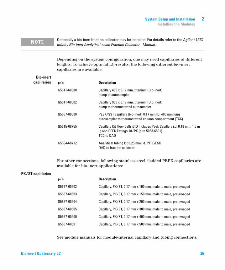
Depending on the system configuration, one may need capillaries of different lengths. To achieve optimal LC-results, the following different bio-inert capillaries are available:
Bio-inertcapillaries
For other connections, following stainless-steel cladded PEEK capillaries are available for bio-inert applications:
PK/ST capillaries
See module manuals for module-internal capillary and tubing connections.
NOTE Optionally a bio-inert fraction collector may be installed. For details refer to the Agilent 1260 Infinity Bio-inert Analytical-scale Fraction Collector - Manual.
p/n Description
G5611-60500 Capillary 400 x 0.17 mm, titanium (Bio-inert)pump to autosampler
G5611-60502 Capillary 900 x 0.17 mm, titanium (Bio-inert)pump to thermostatted autosampler
G5667-60500 PEEK/SST capillary (bio-inert) 0.17 mm ID, 400 mm longautosampler to thermostatted column compartment (TCC)
G5615-68755 Capillary Kit Flow Cells BIO includes Peek Capillary i.d. 0.18 mm, 1.5 m lg and PEEK Fittings 10/PK (p/n 5063-6591)TCC to DAD
G5664-68712 Analytical tubing kit 0.25 mm i.d. PTFE-ESDDAD to fraction collector
p/n Description
G5667-60502 Capillary, PK/ST, 0.17 mm x 100 mm, male to male, pre-swaged
G5667-60503 Capillary, PK/ST, 0.17 mm x 150 mm, male to male, pre-swaged
G5667-60504 Capillary, PK/ST, 0.17 mm x 200 mm, male to male, pre-swaged
G5667-60505 Capillary, PK/ST, 0.17 mm x 300 mm, male to male, pre-swaged
G5667-60500 Capillary, PK/ST, 0.17 mm x 400 mm, male to male, pre-swaged
G5667-60501 Capillary, PK/ST, 0.17 mm x 500 mm, male to male, pre-swaged
Bio-inert Quaternary LC 35

2 System Setup and InstallationInstalling the Modules
Installing Capillaries
Agilent Technologies will introduce new UHP-FF Fittings (planned for 2013). The new fittings are designed for improved robustness and ease of use. Previous fittings require careful handling. Therefore it is important to know, which fittings are used in the system.
The figure below illustrates the differences between new and previous capillaries.
Figure 13 New bio-inert capillary and UHP-FF fitting with nose (planned for 2013)
Figure 14 Previous bio-inert capillary and fitting
NOTE For handling instructions of capillaries and fittings, used in modules before delivery of the new UHP-FF fittings (planned for 2013), refer to “Installation of Stainless Steel Cladded PEEK Capillaries” on page 85.
36 Bio-inert Quaternary LC

System Setup and Installation 2Installing the Modules
Installing UHP-FF Fittings
1 Slide the fitting on the capillary. Let the capillary jut out 5 mm.
Bio-inert Quaternary LC 37

2 System Setup and InstallationInstalling the Modules
2 Insert the fitting to the receiving port and push the capillary to the bottom of the port.
3 Finger tighten the nut into the port until snug.
38 Bio-inert Quaternary LC

System Setup and Installation 2Installing the Modules
4 Use Fitting mounting tool (5043-0915) or a 5 mm hex wrench for fixing the fitting (maximum torque 0.8 Nm).
Bio-inert Quaternary LC 39

2 System Setup and InstallationInstalling the Modules
Installation of the Bio-inert Zero Dead Volume (ZDV) Union
The Bio-inert ZDV (p/n 5067-4741) union has two different connectors where capillaries need to be installed in the correct sequence. Otherwise, an inset of the union may be damaged and the connection may not be tight.
CAUTION Potential leak or damage of the Bio-inert ZDV Union.
➔ To avoid leaks or a damage to the Bio-inert ZDV union, follow the procedure below in the prescribed sequence.
1 Install the capillary at the end marked with a ring/indentation.
2 Install the second capillary at the other end.
40 Bio-inert Quaternary LC

System Setup and Installation 2Installing the Modules
Priming the System
Initial Priming
When Before a degasser or solvent tubing can be used, it is necessary to prime the system. Isopropanol is recommended as priming solvent due to its miscibility with nearly all HPLC solvents and its excellent wetting properties.
Parts required # Description
1 Isopropanol
Preparations Connect all modules hydraulically as described in the respective module manuals.
Fill each solvent bottle with 100 mL isopropanol
Switch the system on
WARNING When opening capillary or tube fittings, solvents may leak out.
The handling of toxic and hazardous solvents and reagents can carry health risks.
➔ Observe appropriate safety procedures (for example, wear goggles, safety gloves and protective clothing) as described in the material handling and safety data sheet supplied by the solvent vendor, especially when toxic or hazardous solvents are used.
NOTE The purge tool of the LabAdvisor or Instrument Utilities can be used to purge the pump automatically.
NOTE If the pump is not able to draw in the solvent from the bottles, use a syringe to move the solvent manually through tubing and degasser.
NOTE When priming the vacuum degasser with a syringe, the solvent is drawn through the degasser tubes very quickly. The solvent at the degasser outlet will therefore not be fully degassed. Pump for approximately 10 minutes at your desired flow rate before starting an analysis. This will allow the vacuum degasser to properly degas the solvent in the degasser tubes.
Bio-inert Quaternary LC 41

2 System Setup and InstallationInstalling the Modules
1 Open the purge valve of the pump
2 Set the flow rate to 5 mL/min.
3 Select channel A1
4 Turn the flow on
5 Observe if the solvent in the tubing of channel A1 is advancing towards the pump. If it isn’t, disconnect the solvent tubing from the solvent selection valve, attach a syringe with a syringe adapter and pull the liquid through the degasser. Reattach the tubing to the solvent selection valve.
6 Pump 30 mL isopropanol to remove residual air bubbles.
7 Switch to the next solvent channel and repeat steps 5 and 6 until all channels have been purged.
8 Turn the flow off and close the purge valve.
42 Bio-inert Quaternary LC
System Setup and Installation 2Installing the Modules
Regular Priming
1 Open the purge valve of your pump by turning it counterclockwise and set the flow rate to 5 mL/min.
2 Flush the vacuum degasser and all tubes with at least 10 mL of solvent.
3 Repeat step 1 and 2 for the other channel(s) of the pump.
4 Set the required composition and flow rate for your application and close the purge valve.
5 Pump for approximately 10 minutes before starting your application.
When When the pumping system has been turned off for a certain time (for example, overnight) air will rediffuse into the solvent channel between the vacuum degasser and the pump. If solvents containing volatile components are left in the degasser without flow for a prolonged period, there will be a slight loss of the volatile components.
Preparations Switch the system on
NOTE The purge tool of the LabAdvisor or Instrument Utilities can be used for automatically purging the pump.
Bio-inert Quaternary LC 43

2 System Setup and InstallationInstalling the Modules
Changing Solvents
1 If the channel is not filled with buffer, proceed to step 4.
2 Place the solvent intake filter into a bottle of water.
3 Flush the channel at a flow rate suitable for the installed tubing (typically 3 – 5 mL/min) for 10 min.
4 Modify the flow path of your system as required for your application. For delay volume optimization, see the Rapid Resolution System manual.
5 Replace the solvent bottle by a bottle of isopropanol.
6 Flush the channel at a flow rate suitable for the installed tubing (typically 3 – 5 mL/min) for 5 min.
7 Swap the bottle of isopropanol with a bottle of solvent for your application.
8 Repeat steps 1 to 7 for the other channel(s) of the pump.
9 Install the desired column, set the required composition and flow rate for your application and equilibrate the system for approx. 10 minutes prior to starting a run.
When When the solvent of a channel is to be replaced by another solvent that is not compatible (solvents are immiscible or one solvent contains a buffer), it is necessary to follow the procedure below to prevent clogging of the pump by salt precipitation or residual liquid droplets in parts of the system.
Parts required # p/n Description
1 Purging solvent(s), see Table 2 on page 45
1 5022-2184 Union ZDV
Preparations Remove the column and replace it by a ZDV fitting.
Prepare bottles with appropriate intermediate solvents (see Table 2 on page 45)
CAUTION Buffer salt of aqueous buffers may precipitate in residual isopropanol.
Capillaries and filter may be clogged by precipitating salt.
➔ Flush solvent lines containing high concentration of salts first with water before introducing organic solvent.
➔ Do not perform steps 5 to 7 for channels running with aqueous buffer as solvent.
44 Bio-inert Quaternary LC

System Setup and Installation 2Installing the Modules
Storage of the system
Never leave the system with buffers containing high salt concentrations or with cleaning solutions such as HCl or NaOH in place. Always flush and purge the system sufficiently with water before storage. For longer periods of storage, use water with 5 – 10 % organic solvent (for example, isopropanol) to prevent algae growth.
Table 2 Choice of Priming Solvents for Different Purposes
Activity Solvent Comments
After an installationWhen switching between reverse phase and normal phase (both times)
IsopropanolIsopropanol
Best solvent to flush air out of the systemMiscible with almost all solvents
After an installation Ethanol or methanol Alternative to isopropanol (second choice) if no isopropanol is available
To clean the system when using buffersAfter changing aqueous solvents
HPLC grade water
HPLC grade water
Best solvent to re-dissolve buffer crystalsBest solvent to re-dissolve buffer crystals
After the installation of normal phase seals ( PE seals (pack of 2) (0905-1420))
Hexane + 5 % isopropanol Good wetting properties
Bio-inert Quaternary LC 45

2 System Setup and InstallationInstalling the Modules
46 Bio-inert Quaternary LC

Bio-inert Quaternary LC
3Quick Start Guide
Preparing the System 48
Turning the System ON 48
Loading the Default Method 49
Configuring the Online Plot 50
Purging the Pump 52
Active Seal Wash 53
Setting Up the Method 54
This chapter provides information on data acquisition and data analysis with the Agilent 1260 Infinity Bio-inert Quaternary LC.
47Agilent Technologies
3 Quick Start GuidePreparing the System
Preparing the System
Turning the System ON
If the system is not already fully on with the software showing Ready status, follow these steps:
1 Turn on the computer system and wait for the Windows desktop to appear.
2 Turn on the electrical power to the LC modules using the button at the lower left of each module.
A green power on light will be visible in the center of the button.
3 Start the control software on the computer by clicking the icon (if configured). Alternatively, you can select Start > All Programs > Agilent Technologies > OpenLAB > OpenLAB Control Panel. Select the relevant instrument in the navigation pane under Instruments, and click Launch online.
The ChemStation software opens in the Method and Run Control view. The modules are initially in Standby mode and Not Ready status, except for the autosampler which immediately initializes and becomes Ready.
4 To switch on each module individually, right-click the relevant icon and select Switch [module name] on from the context menu.
Alternatively, you can turn on all modules simultaneously in the system by clicking the System On/Off button in the bottom right of the system diagram. The system status changes from Not Ready (yellow indication) to Ready (green indication) after a short delay as the setpoints are attained.
48 Bio-inert Quaternary LC

Quick Start Guide 3Preparing the System
Loading the Default Method
The ChemStation has a default method named DEF_LC.M which is loaded at first execution or whenever a new blank method template is required. It contains default settings for all modules.
With this procedure, you load the method DEF_LC.M. You can use it to set all parameters to default settings, or to get a blank method template before setting up a new method.
1 Go to Method and Run Control view of the ChemStation.
2 On the menu bar, select Method > New Method..., and select DEF_LC.M from the context menu.
Alternatively, you can use the Load Method icon under the menu bar, or double-click the method name DEF_LC.M in the Methods tab of the Navigation Pane.
The default method (DEF_LC.M) has a set of default parameters which can then be modified to create a new method. For instance, the flow rate is set to zero, and the Method Information and Method History are blank.
NOTE Note that this method can never be overwritten with new parameters. Hence, clicking on Save will re-direct you into the Save As... function, so that you must enter a different method name.
Bio-inert Quaternary LC 49

3 Quick Start GuidePreparing the System
Configuring the Online Plot
1 If the Online Plot window is not visible, click View > Online Signals > Signal Window 1 to display the window.
50 Bio-inert Quaternary LC

Quick Start Guide 3Preparing the System
2 To configure the desired signal(s) in the Online Plot window, click Change….
The Edit Signal Plot setup page opens.
3 In the Available Signals box, highlight the required signal(s), and click Add to move them to the Selected Signals box.
4 To configure the individual settings for each signal, highlight the signal in the Selected Signal box and set the required values in the lower half of the page.
The Online Plot window behaves like electronic chart paper, continuously recording the output from the detector(s) and other output parameters. The signals are drawn at the right of the window and move away to the left. Up to 60 min of past data is accessible. This is useful for checking the baseline and
NOTE In addition to the detector signals, parameter traces such as temperature and pressure can also be plotted. With Apply to Method, the settings in this page can be stored into the method.
Bio-inert Quaternary LC 51

3 Quick Start GuidePreparing the System
looking at previous injections. The X and Y-axis scales can be adjusted directly with the up/down buttons on each axis.
The Adjust button in the Online Plot window moves the current point on the selected signal to the zero line. The selected signal is indicated by the color of the Y-axis labels. A particular signal may be selected by clicking on the signal or by clicking on the relevant signal description at the top of the plot.
The Balance button zeroes all detectors when pressed.
Purging the Pump
Purge the pump if:
• The pump has been primed for the first time.
• The pump is to be purged with fresh solvent before using the system, or when the solvent is to be exchanged for another.
• The pump has been idle for a few hours or more (air may have diffused into the solvent lines and purging is recommended).
• The solvent reservoirs are refilled, and the pump requires purging to fill the system with fresh solvent. If different solvents are to be used, ensure that the new solvent is miscible with the previous solvent and if necessary use an intermediate step with a co-miscible solvent (isopropanol is often a good choice, check with a solvent miscibility table).
For details on the purging procedure, refer to “Priming the System” on page 41.
NOTE Changes made in the Online Plot page do not in any way affect the data stored into the individual data files.
52 Bio-inert Quaternary LC

Quick Start Guide 3Preparing the System
Active Seal Wash
The active seal wash helps to keep the pump heads clean and prevents salt crystals precipitating and thus ensures longer piston seal lifetime. Therefore the use of the active seal wash is always recommended when operating with bio-molecules and buffer solutions.
You must select this function in the control menu of the pump.
Figure 15 Specify Seal Wash in Pump Control menu
Bio-inert Quaternary LC 53

3 Quick Start GuideSetting Up the Method
Setting Up the Method
This section shows how to quickly set the method conditions for an analysis.
Prerequisites The default method DEF_LC.M has been loaded ready to prepare the new method. Now the key parameters can be edited to create the new method.
1 To quickly access the Method page for each module, right-click in the system diagram for the module and select Method... from the context menu.
Each module is set up in this way.
54 Bio-inert Quaternary LC

Quick Start Guide 3Setting Up the Method
2 Right-click the pump area, and select Method... in the context menu.
a In the Method page for the 1260 Infinity Quaternary Pump, enter the following parameters:
• Flow rate: 1.5 ml/min
• Solvent A: Select Water from the compressibility drop-down list.
• Solvent B: Select the check box to make Solvent B active.
• %B: Initial value 65 %
• Stop Time: 6 min
• Max Pressure Limit:
b Click the + sign to open the Timetable.
c Add a line, select Change Solvent Composition, and set %B to 80 %
d Other parameters can remain at their default settings. Click OK to exit the window.
The changes are sent to the pump module.
3 Right-click the autosampler area, and select Method... in the context menu.
a In the Method page for the 1260 Infinity Autosampler, enter the following parameters:
• Injection volume: 1.0 μl
• Injection with Needle Wash
• Mode Flush Port, Time: 6 s
b Other parameters can remain at their default settings. Click OK to exit the window.
The changes are sent to the autosampler module.
4 Right-click the Thermostatted Column Compartment (TCC) area, and select Method... in the context menu.
a In the Method page for the 1260 Infinity TCC, enter the following parameters:
• Left Temperature 40 °C
• Right Temperature Combined
b Other parameters can remain at their default settings. Click OK to exit the window.
The changes are sent to the TCC module.
Bio-inert Quaternary LC 55

3 Quick Start GuideSetting Up the Method
5 Right-click the Diode-Array Detector area, and select Method... in the context menu.
a In the Method page for the 1260 Infinity DAD VL+, enter the following parameters:
• Use Signal: Turn all signals except Signal A off by clearing the check boxes.
• Signal A: 250 nm, bw 100 nm, ref 360 nm, bw 100 nm
• Peak width: 0.012 min (0.25 s Response, 20 Hz)
b In the Advanced section, set Spectrum Store to All.
c Other parameters can remain at their default settings. Click OK to exit the window.
The changes are sent to the DAD module.
6 All the required module parameters have now been entered. Select Method > Save Method As...ISO-1.M to save the method with a new name.
The ChemStation does not allow the method to be saved as DEF_LC.M so that the default method template is not altered.
7 Allow the system to equilibrate for at least 10 min, and check that the baseline in the Online Plot is stable before starting the analysis.
56 Bio-inert Quaternary LC

Bio-inert Quaternary LC
4Typical Bio-inert LC Applications
Characterization of bio-therapeutics 58
Application Examples 59
This chapter gives an overview on typical Bio-inert LC application examples in protein characterization.
57Agilent Technologies

4 Typical Bio-inert LC ApplicationsCharacterization of bio-therapeutics
Characterization of bio-therapeutics
Physico-chemical characterization and confirmation plays a crucial role in the New Biological Entity (NBE) and biotherapeutics workflow to ensure drug safety and efficacy. Agilent offers a broad spectrum of tools for all assays in order to fulfill the regulatory requirements. For the LC-based tests the Agilent 1260 Infinity Bio-inert Quaternary solution offers a high degree of flexibility to address the needs of a quality control environment as well as flexibility for method development in SEC, ion-exchange, peptide mapping, confirmation and glycan analysis. Therapeutic monoclonal antibodies (mABs, Figure 16 on page 58) are characterized by a variety of assays to ensure drug safety and efficacy. The Agilent 1260 Infinity Bio-inert Quaternary solution is a flexible tool addressing the major requirements.
Figure 16 General structure of Therapeutic Antibodies
58 Bio-inert Quaternary LC
Typical Bio-inert LC Applications 4Application Examples
Application Examples
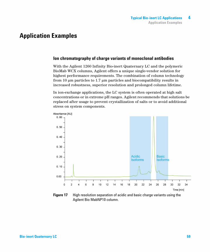
Ion chromatography of charge variants of monoclonal antibodies
With the Agilent 1260 Infinity Bio-inert Quaternary LC and the polymeric BioMab WCX columns, Agilent offers a unique single-vendor solution for highest performance requirements. The combination of column technology from 10 μm particles to 1.7 μm particles and biocompatibility results in increased robustness, superior resolution and prolonged column lifetime.
In ion-exchange applications, the LC system is often operated at high salt concentrations or in extreme pH ranges. Agilent recommends that solutions be replaced after usage to prevent crystallization of salts or to avoid additional stress on system components.
Figure 17 High resolution separation of acidic and basic charge variants using the Agilent Bio MabNP10 column.
Bio-inert Quaternary LC 59

4 Typical Bio-inert LC ApplicationsApplication Examples
Size exclusion chromatography for purity and aggregation analysis
With the Agilent 1260 Infinity Bio-inert Quaternary LC and Bio SEC 5 and Bio SEC 3 columns, robust performance and high reproducibility are obtained under different buffer conditions with or without detergents. In combination with a variety of detectors such as UV and fluorescence, impurities can be easily resolved and detected with superior sensitivity.
Figure 18 Aggregation analysis of a monoclonal antibody
60 Bio-inert Quaternary LC

Typical Bio-inert LC Applications 4Application Examples
Peptide Mapping (Rapid Resolution LC at 600 bar)
The Agilent 1260 Infinity Bio-inert Quaternary LC offers RRLC capability combined with low surface activity, especially for critical samples. In combination with the Agilent Eclipse Plus 1.8 μm particle columns or with the Poroshell 120 stationary phases, high resolution and superior peak capacities are achieved in order to confirm the identity of the analyzed NBE drug in a QA/QC environment.
Figure 19 Peptide map with Agilent Zorbax Eclipse Plus C18 Column
Bio-inert Quaternary LC 61

4 Typical Bio-inert LC ApplicationsApplication Examples
62 Bio-inert Quaternary LC

Bio-inert Quaternary LC
5Specifications
Performance Specifications 64
Solvent Information 71
This chapter provides information about specifications of the 1260 Infinity Bio-inert Quaternary LC system.
63Agilent Technologies

5 SpecificationsPerformance Specifications
Performance Specifications
NOTE For detector specifications, refer to the respective User Manual.
• Diode Array Detector: G1315C
• Multiple Wavelength Detector: G1365C
• Fluorescence Detector: G1321B
64 Bio-inert Quaternary LC

Specifications 5Performance Specifications
Specifications – Agilent 1260 Infinity Bio-inert Quaternary Pump (G5611A)
Table 3 Specifications - Agilent 1260 Infinity Bio-inert Quaternary Pump (G5611A)
Type Specifications
Hydraulic system Dual-piston in-series pump with proprietary servo-controlled variable-stroke drive, floating pistons and active inlet valve, integrated 4-channel degassing unit
Setable flow range 0.001 – 10 mL/min, in 0.001 mL/min increments
Recommended flow range
0.2 – 10 mL/min
Flow precision < 0.07 % RSD, or < 0.02 min SD whichever is the greater, based on retention time at constant room temperature
Flow accuracy ± 1 % or 10 µL/min whichever is the greater
Pressure Operating range up to 60 MPa (600 bar, 8700 psi) up to 5 mL/minOperating range up to 20 MPa (200 bar, 2950 psi) up to 10 mL/min
Pressure pulsation < 2 % amplitude (typically < 1.3 %), at 1 mL/min isopropanol, at all pressures > 1 MPa (10 bar)
Compressibility compensation
User-selectable, based on mobile phase compressibility
Recommended pH range 1 – 13 , short term 141
1 For solvent compatibility, refer to section "Solvent information for parts of the 1260 Infinity Bio-inert LC system" in the manual
Gradient formation Low pressure quaternary mixing/gradient capability using proprietary high-speed proportioning valve.Delay volume 600 – 900 µL, dependent on back pressure.
Composition range 0 – 95 % or 5 – 100 %, user selectable
Composition precision < 0.2 % RSD, at 0.2 and 1 mL/min
Communications Controller-area network (CAN), RS-232C, APG Remote: ready, start, stop and shut-down signals, LAN optional
Materials in flow path Titanium, Gold, Platin-Iridium, Sapphire, PEEK, PTFE
Active seal wash Included
Bio-inert Quaternary LC 65
5 SpecificationsPerformance Specifications
Specifications – Agilent 1260 Infinity Bio-inert High-Performance Autosampler (G5667A)
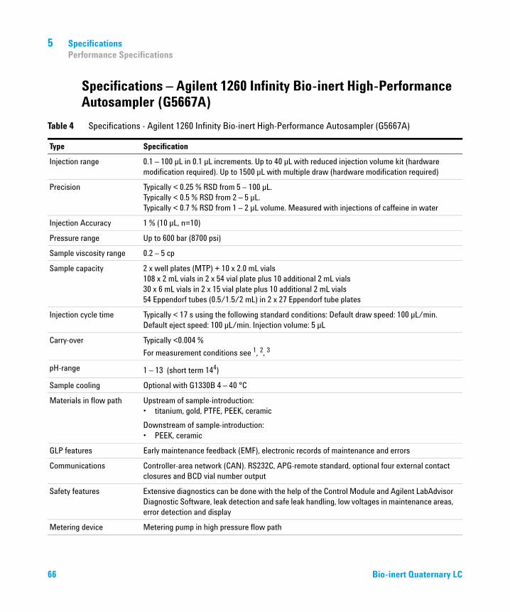
Table 4 Specifications - Agilent 1260 Infinity Bio-inert High-Performance Autosampler (G5667A)
Type Specification
Injection range 0.1 – 100 µL in 0.1 µL increments. Up to 40 µL with reduced injection volume kit (hardware modification required). Up to 1500 µL with multiple draw (hardware modification required)
Precision Typically < 0.25 % RSD from 5 – 100 µL.Typically < 0.5 % RSD from 2 – 5 µL.Typically < 0.7 % RSD from 1 – 2 µL volume. Measured with injections of caffeine in water
Injection Accuracy 1 % (10 µL, n=10)
Pressure range Up to 600 bar (8700 psi)
Sample viscosity range 0.2 – 5 cp
Sample capacity 2 x well plates (MTP) + 10 x 2.0 mL vials108 x 2 mL vials in 2 x 54 vial plate plus 10 additional 2 mL vials30 x 6 mL vials in 2 x 15 vial plate plus 10 additional 2 mL vials54 Eppendorf tubes (0.5/1.5/2 mL) in 2 x 27 Eppendorf tube plates
Injection cycle time Typically < 17 s using the following standard conditions: Default draw speed: 100 µL/min. Default eject speed: 100 µL/min. Injection volume: 5 µL
Carry-over Typically <0.004 %
For measurement conditions see 1, 2, 3
pH-range 1 – 13 (short term 144)
Sample cooling Optional with G1330B 4 – 40 °C
Materials in flow path Upstream of sample-introduction:• titanium, gold, PTFE, PEEK, ceramic
Downstream of sample-introduction:• PEEK, ceramic
GLP features Early maintenance feedback (EMF), electronic records of maintenance and errors
Communications Controller-area network (CAN). RS232C, APG-remote standard, optional four external contact closures and BCD vial number output
Safety features Extensive diagnostics can be done with the help of the Control Module and Agilent LabAdvisor Diagnostic Software, leak detection and safe leak handling, low voltages in maintenance areas, error detection and display
Metering device Metering pump in high pressure flow path
66 Bio-inert Quaternary LC

Specifications 5Performance Specifications
1 Chromatographic conditions: Column: Agilent ZORBAX SB-C18, 2.1 x 50 mm1.8 µm (p/n 827700-902); mobile phase: A: 0.1 % TFA in water, B: 0.1 % TFA in acetonitrile; isocratic : %B=35 %; flow rate: 0.5 mL/min; temperature: 30 °C
2 UV-detection: Sample : 1200 ng/µl chlorhexidine (dissolved in mobile phase A), 1 µL injected and measured on G4212A DAD (10 mm cell); Wavelength: 257 nm +/- 4 nm; ref. 360 nm +/- 16 nm; slit 4 nm, 10 Hz
3 MS-detection: Sample : 50 ng/µl chlorhexidine (dissolved in mobile phase A), 1 µL injected and measured on Agilent 6460 QQQ (in specified conditions); MRM 1: 505.5 ? 170 (CE: 36 V); MRM 2: 505.5 ? 201.2 (CE: 20 V); fragmentor: 150 V, delta EMV(+): 200 V
4 For solvent compatibility, refer to section "Solvent information for parts of the 1260 Infinity Bio-inert LC system" in the manual
Bio-inert Quaternary LC 67

5 SpecificationsPerformance Specifications
Specifications – Bio-inert LC capillaries, connectors, detector flow cells, solvent heating elements and valves
Table 5 Specifications - Bio-inert LC capillaries, connectors, detector flow cells, solvent heating
Capillaries and connectors (complete system)
Materials in flow path Metal-cladded (outside), PEEK, PTFE
pH range 1 – 13 (short term 141)
1 For solvent compatibility, refer to section "Solvent information for parts of the 1260 Infinity Bio-inert LC system" in the manual
600 bar
DAD /MWD flow cells G5615-60022 for G1315 C/D and G1365 C
Materials in flow path PEEK, sapphire window
pH range 1 – 13 (short term 141)
Diode array detector G4212A/B with bio-inert flow cells 10 mm G4212-60008 or 60 mm G4212-60007 high sensitivity flow cells
Materials in flow path PEEK, Fused Silica
pH range 1 – 12 1
Fluorescence detector G1321B with bio-inert flow cell G5621-60005
Materials in flow path PEEK, Fused Silica
pH range 1 – 12 1
Bio-inert heating elements G5616-60050 (9 µL) for G1316C
Materials in flow path PEEK
pH range 1 – 13 (short term 141)
Stand-alone bio-inert valves in G1316C and G1170A
Universal Actuator 2-position/6-port valve head (G5631A) 600 bar max.; PEEK/ceramic
4 column selection valve head (G5639A) 600 bar max.; PEEK/ceramic
12-position/13-port valve head (G4235A) 210 bar max.; PEEK
pH range 1 – 13 (short term 141)
68 Bio-inert Quaternary LC

Specifications 5Performance Specifications
Specifications – Agilent 1260 Infinity Analytical Bio-inert Fraction Collector (G5664A)
Table 6 Specifications - Agilent 1260 Infinity Analytical Bio-inert Fraction Collector (G5664A)
Type Specifications
Delay volume Approximately 50 µL
Maximum system flow 10 mL/min
Fraction containers Shallow or deep well plates up to 48 mm height (96 or 384 format)Test tubes up to 48 mm heightAutosampler Vials (2 mL and 6 mL)Eppendorf safe-lock tubes (0.5 mL, 1.5 mL , 2.5 mL)
Fraction trays Full trays (cover complete fraction collector)4 well plates40 x 20 mL test tubes (30 mm od, 48 mm height)60 x 15 mL test tubes (25 mm od, 48 mm height)126 x 8 mL test tubes (16 mm od, 48 mm height)215 x 5 mL test tubes (12 mm od, 48 mm height)Trays with possibiity to add 1 aditional half tray2 well plates + 10 x 2 mL vials ( + one possible additional half tray)100 x 2 mL vials (+ one possible additional half tray)Half trays (up to 3 per fraction collector)15 x 6 mL vial40 x 2 mL vialPlates for well plate trays (2 or 4 per fraction collector depending on well plate tray)Eppendorf safe-lock tubes (27 x 0.5 mL, 1.5 mL or 2.5 mL)24 test tubes (18 mm OD)54 x 2 mL vial15 x 6 mL vial
Cooling Optional
Trigger modes Time slices and peak (threshold, up-/downslope, upper threshold and timetable), Boolean logic for different detector signals, combination of different modes, manual trigger (supported with Agilent 1200 Series Instant Pilot)
Trigger source Agilent 1200 Infinity Series VWD, MWD and DAD detectors, Agilent 6100 Series Quadrupole LC/MS, ELSD, FLD, RID, third party detectors (require UIB)
Diverter valve 3/2 valve, switching time < 100 ms
Max. pressure 6 bar (diverter valve)
Bio-inert Quaternary LC 69

5 SpecificationsPerformance Specifications
Specifications – Agilent 1260 Infinity Bio-inert Manual Injector (G5628A)
Environment 4 – 55 °C constant temperature, < 95 % humidity (non-condensing)
Materials in flow path PEEK, Ceramic, PTFE
pH range 1 – 13 (short term 14 )1
1 For solvent compatibility, refer to section "Solvent information for parts of the 1260 Infinity Bio-inert LC system" in the manual
Table 6 Specifications - Agilent 1260 Infinity Analytical Bio-inert Fraction Collector (G5664A)
Type Specifications
NOTE Only one type of well-plates can be used at a time in one tray.
Table 7 Specifications - Agilent 1260 Infinity Bio-inert Manual Injector (G5628A)
Type Specifications
Injection valve 2-position/6-port Manual Injection Valve
Loops (PEEK) 20 µL (standard)5 µL – 5 mL (optional)
Materials in flow path PEEK, PTFE, ceramic
pH range 1 – 13 (short term 141)
1 For solvent compatibility, refer to section "Solvent information for parts of the 1260 Infinity Bio-inert LC system" in the manual
70 Bio-inert Quaternary LC

Specifications 5Solvent Information
Solvent Information
Observe the following recommendations on the use of solvents.
• Follow recommendations for avoiding the growth of algae, see pump manuals.
• Small particles can permanently block capillaries and valves. Therefore, always filter solvents through 0.4 μm filters.
• Avoid or minimize the use of solvents that may corrode parts in the flow path. Consider specifications for the pH range given for different materials like flow cells, valve materials etc. and recommendations in subsequent sections.
Solvent information for parts of the 1260 Infinity Bio-inert LC system
For the Agilent 1260 Infinity Bio-inert LC system, Agilent Technologies uses highest quality materials (see “Bio-inert Materials” on page 12) in the flow path (also referred to as wetted parts), which are widely accepted by life scientists, as they are known for optimum inertness to biological samples, and ensure best compatibility to common samples and solvents over a wide pH range. Explicitly, the complete flow path is free from stainless steel and free from other alloys containing metals such as iron, nickel, cobalt, chromium, molybdenum or copper, which can interfere with biological samples. The flow downstream of the sample introduction contains no metals whatsoever.
However, there are no materials that combine suitability for versatile HPLC instrumentation (valves, capillaries, springs, pump heads, flow cells etc.) with complete compatibility with all possible chemicals and application conditions. This section recommends the preferred solvents. Chemicals that are known to cause issues should be avoided, or exposure should be minimized, for example, for short-term cleaning procedures. After potentially aggressive chemicals have been used, the system should be flushed with compatible standard HPLC solvents.
Bio-inert Quaternary LC 71

5 SpecificationsSolvent Information
PEEK
PEEK (Polyether-Ether Ketones) combines excellent properties with regard to biocompatibility, chemical resistance, mechanical and thermal stability and is therefore the material of choice for biochemical instrumentation. It is stable in the specified pH range, and inert to many common solvents. There is still a number of known incompatibilities with chemicals such as chloroform, methylene chloride, THF, DMSO, strong acids (nitric acid > 10 %, sulphuric acid > 10 %, sulfonic acids, trichloroacetic acid), halogenes or aequous halogene solutions, phenol and derivatives (cresols, salicylic acid etc.).
When used above room temperature, PEEK is sensitive to bases and various organic solvents, which can cause it to swell. As normal PEEK capillaries are very sensitive to high pressure, especially under such conditions, Agilent uses stainless-steel cladded PEEK capillaries to keep the flow path free of steel and to ensure pressure stability to at least 600 bar. If in doubt, consult the available literature about the chemical compatibility of PEEK.
Titanium
Titanium is highly resistant to oxidizing acids (for example, nitric, perchloric and hypochlorous acid) over a wide range of concentrations and temperatures. This is due to a thin oxide layer on the surface, which is stabilized by oxidizing compounds. Reducing acids (for example, hydrochloric, sulfuric and phosphoric acid) can cause slight corrosion, which increases with acid concentration and temperature. For example, the corrosion rate with 3 % HCl (about pH 0.1) at room temperature is about 13 μm/year. At room temperature, titanium is resistant to concentrations of about 5 % sulfuric acid (about pH 0.3). The addition of nitric acid to hydrochloric or sulfuric acids significantly reduces corrosion rates. Titanium is subject to corrosion in anhydrous methanol, which can be avoided by adding a small amount of water (about 3 %). Slight corrosion is possible with ammonia > 10 %.
Fused silica
Fused silica is inert against all common solvents and acids except hydrofluoric acid. It is corroded by strong bases and should not be used above pH 12 at room temperature. The corrosion of flow cell windows can negatively affect measurement results. For a pH greater than 12, the use of flow cells with sapphire windows is recommended.
72 Bio-inert Quaternary LC

Specifications 5Solvent Information
Gold
Gold is inert to all common HPLC solvents, acids and bases within the specified pH range. It can be corroded by complexing cyanides and concentrated acids like aqua regia (a mixture of concentrated hydrochloric and nitric acid).
Zirconium Oxide
Zirconium Oxide (ZrO2) is inert to almost all common acids, bases and
solvents. There are no documented incompatibilities for HPLC applications.
Platinum/Iridium
Platinum/Iridium is inert to almost all common acids, bases and solvents. There are no documented incompatibilities for HPLC applications.
PTFE
PTFE (polytetrafluorethen) is inert to almost all common acids, bases and solvents. There are no documented incompatibilities for HPLC applications.
Sapphire, Ruby and Al2O3-based ceramics
Sapphire, ruby and ceramics based on Al2O3 are inert to almost all common
acids, bases and solvents. There are no documented incompatibilities for HPLC applications.
Data above were collected from external resources and are meant as a reference. Agilent cannot guarantee the completeness and correctness of such information. Information can also not be generalized due to catalytic effects of impurities like metal ions, complexing agents, oxygen etc. Most data available refers to room temperature (typically 20 – 25 °C, 68 – 77 °F). If corrosion is possible, it usually increases at higher temperatures. If in doubt, consult additional resources.
Bio-inert Quaternary LC 73

5 SpecificationsSolvent Information
Flow Cell
To protect optimal functionality of your flow cell:
• Standard flow cell bio-inert, 10 mm, 13 μL, 120 bar ( 12 MPa) for MWD/DAD, includes Capillary Kit Flow Cells BIO (p/n G5615-68755) (G5615-60022) (PEEK, ceramic, sapphire, PTFE) for 1260 Infinity Diode Array Detectors (G1315C/D):
• The recommended pH range of the cell is 1 – 13 (short term 14)
• Max-Light Cartridge Cell Bio-inert ( 60 mm, V(s) 4.0 μL) (G5615-60017) and Max-Light Cartridge Cell Bio-inert ( 10 mm, V(s) 1.0 μL) (G5615-60018) (PEEK, fused silica) for 1260 and 1290 Infinity Diode Array Detectors (G4212A/B):
• The recommended pH range of the cell is 1 – 12 (solvent dependent).
• Bio-inert flow cell, 8 μL, 20 bar (pH 1–12) includes Capillary Kit Flow Cells BIO (p/n G5615-68755) (G5615-60005), (PEEK, fused silica, PTFE) for 1260 Infinity Fluorescence Detector (G1321B)
• The recommended pH range of the cell is 1 – 12 (solvent dependent).
• If the flow cell is transported while temperatures are below 5 °C, it must be ensured that the cell is filled with alcohol to avoid damage by freezing water.
• Aqueous solvents in the flow cell can build up algae. Therefore, do not leave aqueous solvents sitting in the flow cell. Add a small percentage of organic solvents (for example, about 5 % of acetonitrile or methanol).
74 Bio-inert Quaternary LC

Bio-inert Quaternary LC
6Appendix
Safety 76
The Waste Electrical and Electronic Equipment Directive 79
Lithium Batteries Information 80
Radio Interference 81
Sound Emission 82
UV Radiation 83
Declaration of Conformity for HOX2 Filter 84
Installation of Stainless Steel Cladded PEEK Capillaries 85
First Step: Finger-tight Fitting 86
Second Step: Installation to Connector 86
Removing Capillaries 90
Agilent Technologies on Internet 91
This chapter provides addition information on safety, legal and web
75Agilent Technologies
6 AppendixSafety
Safety
Safety Symbols
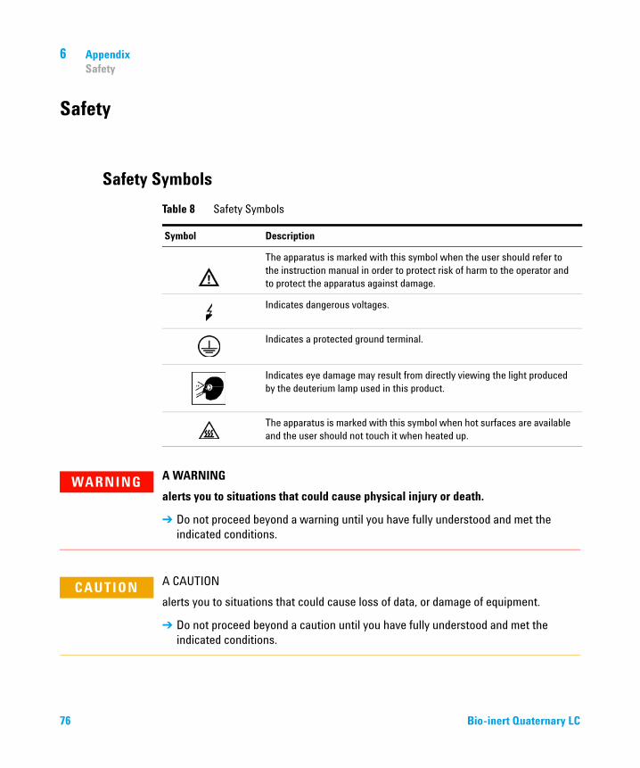
Table 8 Safety Symbols
Symbol Description
The apparatus is marked with this symbol when the user should refer to the instruction manual in order to protect risk of harm to the operator and to protect the apparatus against damage.
Indicates dangerous voltages.
Indicates a protected ground terminal.
Indicates eye damage may result from directly viewing the light produced by the deuterium lamp used in this product.
The apparatus is marked with this symbol when hot surfaces are available and the user should not touch it when heated up.
WARNING A WARNING
alerts you to situations that could cause physical injury or death.
➔ Do not proceed beyond a warning until you have fully understood and met the indicated conditions.
CAUTION A CAUTION
alerts you to situations that could cause loss of data, or damage of equipment.
➔ Do not proceed beyond a caution until you have fully understood and met the indicated conditions.
76 Bio-inert Quaternary LC
Appendix 6Safety
General Safety Information
The following general safety precautions must be observed during all phases of operation, service, and repair of this instrument. Failure to comply with these precautions or with specific warnings elsewhere in this manual violates safety standards of design, manufacture, and intended use of the instrument. Agilent Technologies assumes no liability for the customer’s failure to comply with these requirements.
Safety Standards
This is a Safety Class I instrument (provided with terminal for protective earthing) and has been manufactured and tested according to international safety standards.
Operation
Before applying power, comply with the installation section. Additionally the following must be observed.
Do not remove instrument covers when operating. Before the instrument is switched on, all protective earth terminals, extension cords, auto-transformers, and devices connected to it must be connected to a protective earth via a ground socket. Any interruption of the protective earth grounding will cause a potential shock hazard that could result in serious personal injury. Whenever it is likely that the protection has been impaired, the instrument must be made inoperative and be secured against any intended operation.
Make sure that only fuses with the required rated current and of the specified type (normal blow, time delay, and so on) are used for replacement. The use of repaired fuses and the short-circuiting of fuse holders must be avoided.
WARNING Ensure the proper usage of the equipment.
The protection provided by the equipment may be impaired.
➔ The operator of this instrument is advised to use the equipment in a manner as specified in this manual.
Bio-inert Quaternary LC 77

6 AppendixSafety
Some adjustments described in the manual, are made with power supplied to the instrument, and protective covers removed. Energy available at many points may, if contacted, result in personal injury.
Any adjustment, maintenance, and repair of the opened instrument under voltage should be avoided whenever possible. When inevitable, this has to be carried out by a skilled person who is aware of the hazard involved. Do not attempt internal service or adjustment unless another person, capable of rendering first aid and resuscitation, is present. Do not replace components with power cable connected.
Do not operate the instrument in the presence of flammable gases or fumes. Operation of any electrical instrument in such an environment constitutes a definite safety hazard.
Do not install substitute parts or make any unauthorized modification to the instrument.
Capacitors inside the instrument may still be charged, even though the instrument has been disconnected from its source of supply. Dangerous voltages, capable of causing serious personal injury, are present in this instrument. Use extreme caution when handling, testing and adjusting.
When working with solvents, observe appropriate safety procedures (for example, goggles, safety gloves and protective clothing) as described in the material handling and safety data sheet by the solvent vendor, especially when toxic or hazardous solvents are used.
78 Bio-inert Quaternary LC

Appendix 6The Waste Electrical and Electronic Equipment Directive
The Waste Electrical and Electronic Equipment Directive
Abstract
The Waste Electrical and Electronic Equipment (WEEE) Directive (2002/96/EC), adopted by EU Commission on 13 February 2003, is introducing producer responsibility on all electric and electronic appliances starting with 13 August 2005.
NOTE This product complies with the WEEE Directive (2002/96/EC) marking requirements. The affixed label indicates that you must not discard this electrical/electronic product in domestic household waste.
Product Category:
With reference to the equipment types in the WEEE Directive Annex I, this product is classed as a Monitoring and Control Instrumentation product.
NOTE Do not dispose off in domestic household waste
To return unwanted products, contact your local Agilent office, or see www.agilent.com for more information.
Bio-inert Quaternary LC 79

6 AppendixLithium Batteries Information
Lithium Batteries Information
WARNING Lithium batteries may not be disposed-off into the domestic waste. Transportation of discharged Lithium batteries through carriers regulated by IATA/ICAO, ADR, RID, IMDG is not allowed.
Danger of explosion if battery is incorrectly replaced.
➔ Discharged Lithium batteries shall be disposed off locally according to national waste disposal regulations for batteries.
➔ Replace only with the same or equivalent type recommended by the equipment manufacturer.
WARNING Lithiumbatteri - Eksplosionsfare ved fejlagtig håndtering.
Udskiftning må kun ske med batteri af samme fabrikat og type.
➔ Lever det brugte batteri tilbage til leverandøren.
WARNING Lithiumbatteri - Eksplosionsfare.
Ved udskiftning benyttes kun batteri som anbefalt av apparatfabrikanten.
➔ Brukt batteri returneres appararleverandoren.
NOTE Bij dit apparaat zijn batterijen geleverd. Wanneer deze leeg zijn, moet u ze niet weggooien maar inleveren als KCA.
80 Bio-inert Quaternary LC

Appendix 6Radio Interference
Radio Interference
Cables supplied by Agilent Technologies are screened to provide optimized protection against radio interference. All cables are in compliance with safety or EMC regulations.
Test and Measurement
If test and measurement equipment is operated with unscreened cables, or used for measurements on open set-ups, the user has to assure that under operating conditions the radio interference limits are still met within the premises.
Bio-inert Quaternary LC 81

6 AppendixSound Emission
Sound Emission
Manufacturer’s Declaration
This statement is provided to comply with the requirements of the German Sound Emission Directive of 18 January 1991.
This product has a sound pressure emission (at the operator position) < 70 dB.
• Sound Pressure Lp < 70 dB (A)
• At Operator Position
• Normal Operation
• According to ISO 7779:1988/EN 27779/1991 (Type Test)
82 Bio-inert Quaternary LC

Appendix 6UV Radiation
UV Radiation
Emissions of ultraviolet radiation (200 – 315 nm) from this product is limited such that radiant exposure incident upon the unprotected skin or eye of operator or service personnel is limited to the following TLVs (Threshold Limit Values) according to the American Conference of Governmental Industrial Hygienists:
Typically the radiation values are much smaller than these limits:
Table 9 UV radiation limits
Exposure/day Effective irradiance
8 h 0.1 µW/cm2
10 min 5.0 µW/cm2
Table 10 UV radiation typical values
Position Effective irradiance
Lamp installed, 50 cm distance average 0.016 µW/cm2
Lamp installed, 50 cm distance maximum 0.14 µW/cm2
Bio-inert Quaternary LC 83

6 AppendixDeclaration of Conformity for HOX2 Filter
Declaration of Conformity for HOX2 Filter
84 Bio-inert Quaternary LC

Appendix 6Installation of Stainless Steel Cladded PEEK Capillaries
Installation of Stainless Steel Cladded PEEK Capillaries
The 1260 Infinity Bio-inert LC system uses PEEK capillaries that are cladded with stainless steel. These capillaries combine the high pressure stability of steel with the inertness of PEEK. They are used in the high pressure flow path after sample introduction (loop/needle seat capillary) through the thermostatted column compartment/heat exchangers to the column. Such capillaries need to be installed carefully in order to keep them tight without damaging them by over-tightening.
Installation procedure
The amount of force/torque needing to be applied to install the capillary depends on
• the female connector to which the capillary is installed, and whether the material of that connector is soft or hard. Compared with hard connectors, a greater tightening angle is required for soft connectors to achieve same torque.
• whether the capillary is installed for the first time or subsequent times. For the first time, a greater tightening angle needs to be applied.
The installation consists of two steps. In the first step, the fitting is installed finger-tight without using tools. Finger-tight means that the fitting will grip and hold the capillary. This brings the fitting to the appropriate start position (marked as 0 ° below) for the second step.
NOTE This installation procedure applies for capillaries and corresponding fittings used in modules delivered before January 2013. For current capillaries and fittings, see “Installing UHP-FF Fittings” on page 37.
CAUTION Handling of stainless-steel-cladded PEEK capillaries
Be careful when installing stainless-steel-cladded PEEK capillaries. The correct torque must be applied to avoid leaks potentially causing measurement problems or damage to the capillary.
➔ Follow the procedure below for a correct installation
Bio-inert Quaternary LC 85
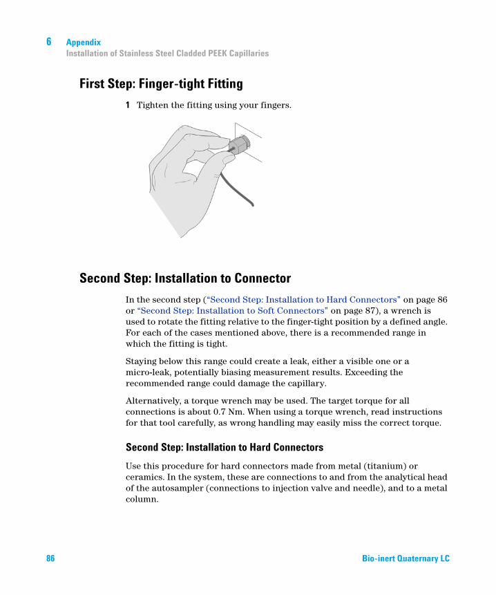
6 AppendixInstallation of Stainless Steel Cladded PEEK Capillaries
First Step: Finger-tight Fitting
1 Tighten the fitting using your fingers.
Second Step: Installation to Connector
In the second step (“Second Step: Installation to Hard Connectors” on page 86 or “Second Step: Installation to Soft Connectors” on page 87), a wrench is used to rotate the fitting relative to the finger-tight position by a defined angle. For each of the cases mentioned above, there is a recommended range in which the fitting is tight.
Staying below this range could create a leak, either a visible one or a micro-leak, potentially biasing measurement results. Exceeding the recommended range could damage the capillary.
Alternatively, a torque wrench may be used. The target torque for all connections is about 0.7 Nm. When using a torque wrench, read instructions for that tool carefully, as wrong handling may easily miss the correct torque.
Second Step: Installation to Hard Connectors
Use this procedure for hard connectors made from metal (titanium) or ceramics. In the system, these are connections to and from the analytical head of the autosampler (connections to injection valve and needle), and to a metal column.
86 Bio-inert Quaternary LC

Appendix 6Installation of Stainless Steel Cladded PEEK Capillaries
First installation of a capillary to a hard connector
1 When tightening a fitting for the first time, start from the finger-tight position (which is not necessarily a vertical wrench position) and rotate the wrench by 135 – 180 °. Staying below 135 ° (grey arrow) will be insufficiently tight, more than 180 ° (red arrow) could damage the capillary.
Second and subsequent installations of a capillary to a hard connector
1 When tightening the fitting for the second and subsequent times, again start from the finger-tight position (which is not necessarily a vertical wrench position) and rotate the wrench by 90 – 135 °. Staying below 90 ° (grey arrow) could be insufficiently tight, more than 135 ° (red arrow) could damage the capillary.
Second Step: Installation to Soft Connectors
Use this procedure for soft connectors, which are typically made from PEEK. These are the following connections:
• to and from all bio-inert valves (injection valve in the autosampler and valves in the thermostatted column compartment and 1290 Infinity Valve Drive),
• bio-inert ZDV unions (detector flow cells, multi-draw upgrade kit, capillary to capillary connections, for example, for heat exchangers),
Bio-inert Quaternary LC 87

6 AppendixInstallation of Stainless Steel Cladded PEEK Capillaries
• to the autosampler needle and
• to PEEK columns (like many bio-inert columns).
For the installation of bio-inert ZDV unions, see “Installation of the Bio-inert Zero Dead Volume (ZDV) Union” on page 40.
First installation of a capillary to a soft connector
1 When tightening a fitting for the first time, start from the finger-tight position (which does not necessarily need to be a vertical wrench position) and rotate the wrench by 180 – 210 °. Staying below 180 ° (grey arrow) will not be sufficiently tight, more than 210 ° (red arrow) could damage the capillary.
Second and subsequent installations of a capillary to a soft connector
1 When tightening the fitting for the second and subsequent times, again start from the finger-tight position (which is not necessarily a vertical wrench position) and rotate the wrench by 135 – 180 °. Staying below 135 ° (grey arrow) could be insufficiently tight enough, more than 180 ° (red arrow) could damage the capillary.
88 Bio-inert Quaternary LC

Appendix 6Installation of Stainless Steel Cladded PEEK Capillaries
Summary for Second Step
Table 11 Summary for second step
2ndStep First installation Subsequent installations
Hard connectors
Soft connectors
Bio-inert Quaternary LC 89
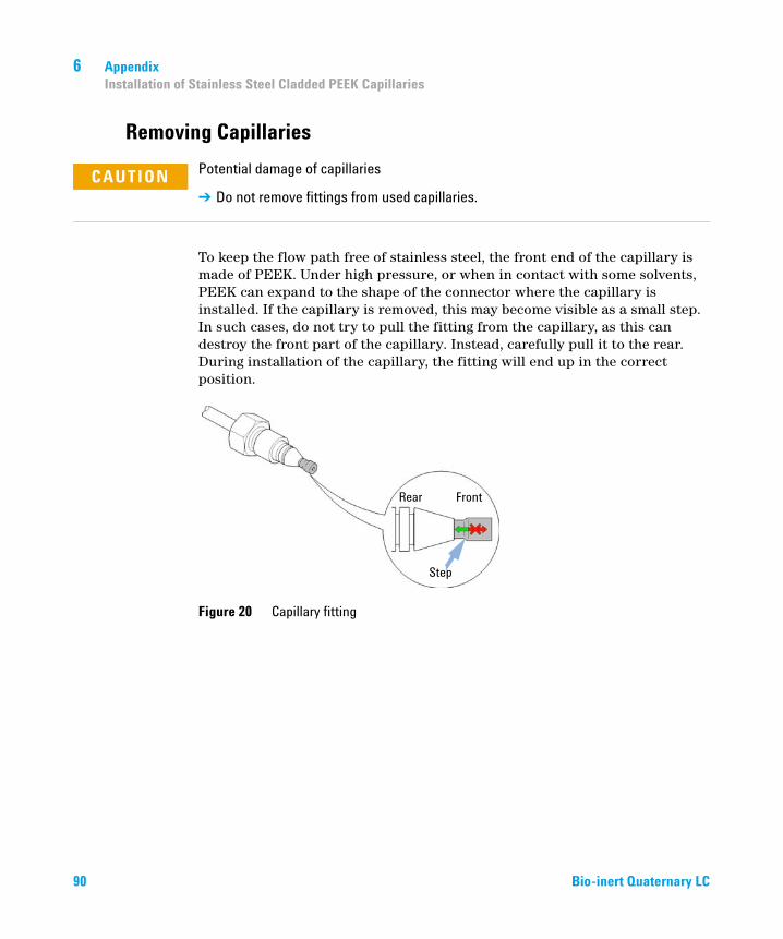
6 AppendixInstallation of Stainless Steel Cladded PEEK Capillaries
Removing Capillaries
To keep the flow path free of stainless steel, the front end of the capillary is made of PEEK. Under high pressure, or when in contact with some solvents, PEEK can expand to the shape of the connector where the capillary is installed. If the capillary is removed, this may become visible as a small step. In such cases, do not try to pull the fitting from the capillary, as this can destroy the front part of the capillary. Instead, carefully pull it to the rear. During installation of the capillary, the fitting will end up in the correct position.
Figure 20 Capillary fitting
CAUTION Potential damage of capillaries
➔ Do not remove fittings from used capillaries.
90 Bio-inert Quaternary LC

Appendix 6Agilent Technologies on Internet
Agilent Technologies on Internet
For the latest information on products and services visit our worldwide web site on the Internet at:
http://www.agilent.com
Bio-inert Quaternary LC 91

Index
Index
Aactive seal wash 53
Agilenton internet 91
algae 74
Bbattery
safety information 80
bio-inertmaterials 12
bio-therapeuticscharacterization 58
Cchanging solvents 44
chromatographysize exclusion 60
componentautosampler 10detector 11fraction collector 11pump 10solvent cabinet 10TCC 11
componentssystem 10
conceptsbio-inert 8
configurationone stack 15two stack 17
configuringonline plot 50
Ddeclaration of conformity 84
default methodloading 49
Eelectronic waste 79
Fflow cell 74
solvent information 74
fraction collectoroverview 29
Hholmium oxide
declaration of conformity 84
Iinformation
on UV radiation 83
installingLab Advisor 32
internet 91
ion-exchangetruncation 59
Llithium batteries 80
loadingdefault 49
Mmanual injector 24
mappingpeptide 61
materialsbio-inert 12
methodsetting up 54
Nnetwork integration 33
Oonline plot
configuring 50
optimizationstack configuration 14
overview, pump 19
Ppeptide
mapping 61
primingwith a pump 43
propertiessystem 9
Rradio interference 81
Ssafety class I 77
safety information
92 Bio-inert Quaternary LC

Index
lithium batteries 80
safetygeneral information 77symbols 76
solvent information 71
solvents, change 44
sound emission 82
system setup and installationnetwork Integration 33optimizing stack configuration 14
systemturning on 48
Tthermostatted column compartment
overview 25
UUV radiation 83
Wwaste
electrical and electronic equipment 79
WEEE directive 79
Bio-inert Quaternary LC 93

www.agilent.com
In This Book
This book describes the Agilent 1260 Infinity Bio-inert Quaternary LC System
The manual describes the following:
• Introduction
• System Setup and Installation
• Quick Start Guide
• Typical Bio-inert LC Applications
• Optimiziation of the Agilent 1260 Infinity Bio-inert Quaternary LC
• Specifications
• Appendix
© Agilent Technologies 2011-2012
Printed in Germany 11/2012
*G5611-90301**G5611-90301*G5611-90301
Agilent Technologies