Agenda - Welcome to ERPC – Eastern Regional Power...
49
Agenda for 61 st PCC meeting Date: 28.11.2017 Eastern Regional Power Committee 14, Golf Club Road, Tollygunge Kolkata: 700 033
Transcript of Agenda - Welcome to ERPC – Eastern Regional Power...

Agenda for
61st PCC meeting
Date: 28.11.2017 Eastern Regional Power Committee
14, Golf Club Road, Tollygunge Kolkata: 700 033

EASTERN REGIONAL POWER COMMITTEE
AGENDA FOR 61ST PROTECTION SUB-COMMITTEE MEETING TO BE HELD AT
ERPC, KOLKATA ON 28.11.2017 (TUESDAY) AT 11:00 HOURS
PART – A
ITEM NO. A.1: Confirmation of minutes of 60th Protection sub-Committee Meeting held on
24th October, 2017 at ERPC, Kolkata. The minutes of 60th Protection Sub-Committee meeting held on 24.10.17 circulated vide letter dated 31.10.17. Members may confirm the minutes of 60th PCC meeting.
PART – B
ANALYSIS & DISCUSSION ON GRID INCIDENCES OCCURRED IN OCTOBER, 2017 ITEM NO. B.1: Disturbance at 400 kV Teesta-V S/s on 12-10-17 at 12:55 hrs At 12:55 hrs, heavy sound was observed in the vicinity of 400kV Teesta V and 400 kV Teesta - Rangpo - II tripped on zone 2, Y-N fault from Rangpo end. Teesta end distance protection not observed any fault in the line. Carrier received at Teesta end and Auto reclose operation of 400 kV Teesta - Rangpo - II was successful at Teesta end. In the mean time, B/C at Teesta tripped on O/C, E/F protection, high set stage II resulting tripping of unit III due to loss of evacuation path. Relay Indications:
Time Name of the element Relay at Local end Relay at remote end 12:55:43 hrs
400 kV Teesta - Rangpo - II
Y-N, AR initiated. Tripped on receipt of carrier trip
Y-N, F/C: 4.789, Zone 2, F/D: 18.25 KM. Line length actually 12.323 km. Current:- IA: 173.8A, IB: 4.789 kA, IC: 356.3A Voltage:- VAN: 244.7KV, VBN: 190.5KV, VCN: 236.1KV
12:55:37 hrs
400kV Bus coupler at Teesta
O/C, E/F relay (stage 2)
12:55:48 hrs
Unit III of Teesta V Over frequency relay
Generation loss 170 MW Fault clearing time as per PMU data is 600 ms. NHPC informed that stage-II high set setting of O/C, E/F protection of Bus coupler has been revised from 2A, Instantaneous to 2A, 100 ms time delay. Powergrid and NHPC may explain the following:
Powergrid may explain the status of Auto reclose operation at Rangpo end. Location of the fault

61st PCC Agenda 2
ITEM NO. B.2: Repeated disturbances at 400kV Teesta III on 13-10-17 at 14:39 hrs, 26-10-17 at 12:02 hrs and 27-10-17 at 13:17 hrs
1. 13-10-17 at 14:39 hrs
400 kV Teesta III - Rangpo S/C tripped due to Y-B fault resulting tripping of unit I, III, IV, V & VI at Teesta III and running unit at Dikchu. Relay indication: Y-B, Z-I, 29.4 km from Teesta III, F/C 4.16 kA, 3.22 kA. (Loss of generation at Teesta III: 0.1299 MU). Generation loss 750 MW. Fault clearing time as per PMU data is less than 100 ms. Teesta Urja and Powergrid may explain with the relay indications and DR.
2. 19-10-17 at 11:55 hrs 400 KV Teesta III-Dikchu S/C tripped on Y-B-N fault resulting loss of unit II at Dikchu. Generation loss 58 MW Fault clearing time as per PMU data is less than 100 ms. Teesta Urja and Dikchu may explain with the relay indications and DR.
3. 26-10-17 at 12:02 hrs 400 kV Teesta III – Dikchu S/C along with all running units at Teesta III tripped on O/V (as reported by Teesta III) at Teesta III end. Running unit (U#1) at Dikchu tripped due to loss of evacuation path. Breaker of 400 kV Teesta III – Dikchu S/C at Dikchu end was manually opened at 12:07 hrs. No fault is observed in PMU data. Voltage at Teesta III is 409 kV (as per ERLDC SCADA data). Both the buses in Teesta III were in live condition as 400 kV Teesta III – Rangpo S/C did not trip. Generation loss 460 MW Teesta Urja and Dikchu may explain with the relay indications and DR.
4. 27-10-17 at 13:17 hrs 400 kV Teesta III – Dikchu S/C along with all running units at Teesta III tripped due to DC earth fault at Teesta III end. Running unit (U#1) at Dikchu tripped due to loss of evacuation path. Breaker of 400 kV Teesta III – Dikchu S/C at Dikchu end was manually opened at 13:20 hrs. No fault is observed in PMU data. Voltage at Teesta III is 409 kV (as per ERLDC SCADA data). Both the buses in Teesta III in live condition as 400 kV Teesta III – Rangpo S/C did not trip. Generation loss 850 MW Teesta Urja and Dikchu may explain with the relay indications and DR. ITEM NO. B.3: Disturbance at 132 kV Purnea S/s on 18-10-17 at 18:19 hrs At 18:19 hrs, 132 KV Purnea(PG) - Purnea(BSPTCL) T/C tripped (from PG end only) due to failure of B phase jumper of line isolator at Bihar end of 132 KV Purnea-Purnea - III. 132 KV Purnea (BSPTCL)- Purnea (PG) CKT-III tripped at Purnea (BSPTCL) end on O/C & E/F relay (Micom 142) and Master trip relay in 411 ms. All the three ckts tripped from Powergrid.

61st PCC Agenda 3
Simultaneously 132 KV Purnea (PG) - Phorbisganj S/C tripped on overload resulting total power failure at 132 /33KV Purnea S/S (BSPTCL). 132 KV Khagaria & Naugachia shifted to Barauni source. Load loss 200 MW Fault clearing time as per PMU data is 350 ms. Powergrid and BSPTCL may explain with the relay indications and DR. ITEM NO. B.4: Disturbance at 220 kV Madhepura S/s on 20-10-17 at 23:53 hrs Total power failure occurred at Madhepura, Saharsa, Sonebarsa and Udaikishanganj due to tripping of 220 kV Purnea - Madhepura D/C on Y-N fault. Load loss 124 MW Fault clearing time as per PMU data is less than 100 ms. Powergrid and BSPTCL may explain with the relay indications and DR. ITEM NO. B.5: Disturbance at 132 kV Sultanganj S/s on 26-10-17 at 09:22 hrs Total power failure occurred at Sultanganj, Tarapur and Part of Munger after tripping of 132 kV Banka – Sultanganj D/C in R-N fault (Relay Indication: Ckt II: R-N, F/C 2.19 kA, 41.27 km from Banka, Ckt I: R-N, 2.8 kA, 31.62 km from Banka). Load loss 32 MW Fault clearing time as per PMU data is less than 100 ms. Powergrid and BSPTCL may explain with the relay indications and DR. ITEM NO. B.6: Disturbance at 220 kV Chandaka(OPTCL) on 17-10-17 at 10:23 hrs 220 kV Mendasal - Chandaka Q/C line tripped due to fault in 220 kV Mendasal - Chandaka - I resulting total power failure at Chandaka end. Power was extended to Chandaka by charging circuit II. Load loss 230 MW. Fault clearing time as per PMU data is 1000 ms. OPTCL may explain with the relay indications and DR. ITEM NO. B.7: Disturbance at 220 kV Budhipadar S/s on 01-10-17 at 09:25 hrs Prior to the incident, 220 kV Korba III feeder was in idle charged up to location 24 from Budhipadar end. At 09:25 hrs, fault occurred at idle charged portion and line tripped from Budhipadar end in Z-I protection. At same time, all elements connected to 220 kV Bus I tripped at Budhipadar due to operation of bus bar protection. It is observed that, the fault current recorded by Korba-3 feeder in B-phase is IL3/In=15.0. The sum of the fault current contribution from all other feeder of Bus-I also found to be IL3/In=15.0. So, no differential current is available but Bus bar relay operates for Bus-1 & tripped all the feeders of Bus-I. Fault clearing time as per PMU data is less than 100 ms. OPTCL may explain with the relay indications and DR.
61st PCC Agenda 4
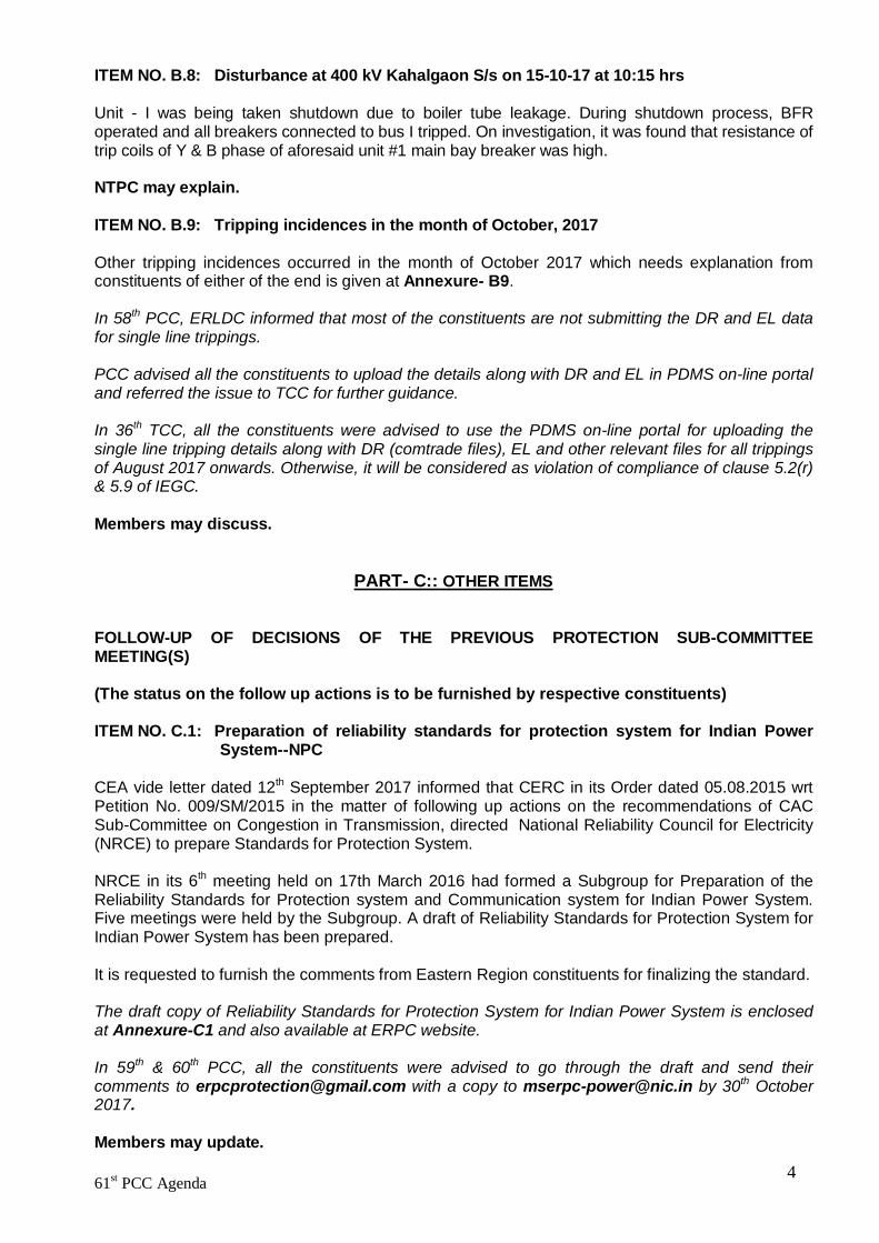
ITEM NO. B.8: Disturbance at 400 kV Kahalgaon S/s on 15-10-17 at 10:15 hrs Unit - I was being taken shutdown due to boiler tube leakage. During shutdown process, BFR operated and all breakers connected to bus I tripped. On investigation, it was found that resistance of trip coils of Y & B phase of aforesaid unit #1 main bay breaker was high. NTPC may explain. ITEM NO. B.9: Tripping incidences in the month of October, 2017 Other tripping incidences occurred in the month of October 2017 which needs explanation from constituents of either of the end is given at Annexure- B9. In 58th PCC, ERLDC informed that most of the constituents are not submitting the DR and EL data for single line trippings. PCC advised all the constituents to upload the details along with DR and EL in PDMS on-line portal and referred the issue to TCC for further guidance. In 36th TCC, all the constituents were advised to use the PDMS on-line portal for uploading the single line tripping details along with DR (comtrade files), EL and other relevant files for all trippings of August 2017 onwards. Otherwise, it will be considered as violation of compliance of clause 5.2(r) & 5.9 of IEGC. Members may discuss.
PART- C:: OTHER ITEMS
FOLLOW-UP OF DECISIONS OF THE PREVIOUS PROTECTION SUB-COMMITTEE MEETING(S)
(The status on the follow up actions is to be furnished by respective constituents) ITEM NO. C.1: Preparation of reliability standards for protection system for Indian Power
System--NPC CEA vide letter dated 12th September 2017 informed that CERC in its Order dated 05.08.2015 wrt Petition No. 009/SM/2015 in the matter of following up actions on the recommendations of CAC Sub-Committee on Congestion in Transmission, directed National Reliability Council for Electricity (NRCE) to prepare Standards for Protection System. NRCE in its 6th meeting held on 17th March 2016 had formed a Subgroup for Preparation of the Reliability Standards for Protection system and Communication system for Indian Power System. Five meetings were held by the Subgroup. A draft of Reliability Standards for Protection System for Indian Power System has been prepared. It is requested to furnish the comments from Eastern Region constituents for finalizing the standard. The draft copy of Reliability Standards for Protection System for Indian Power System is enclosed at Annexure-C1 and also available at ERPC website. In 59th & 60th PCC, all the constituents were advised to go through the draft and send their comments to [email protected] with a copy to [email protected] by 30th October 2017. Members may update.

61st PCC Agenda 5
ITEM NO. C.2: Checklist for submission of updated data for Protection Database
The network data in Protection Database needs to be updated on regular basis on account of commissioning of new elements in the CTU as well as STU networks. Accordingly a checklist has been prepared which is enclosed in Annexure-C2. All the constituents requested to submit the checklist on monthly bases in every OCC/PCC meetings. Constituents may update. ITEM NO. C.3: Repeated disturbances at 132 kV Rangit, Kurseong, Melli and Rangpo on 30-
08-17 at 05:15 hrs and 31-08-17 at 00:39 hrs 30-08-17 at 05:15 hrs: At 5:15 hrs. 132 KV Siliguri-Kurseong S/C, 132 KV Siliguri Melli S/C and 132 KV Rangit-Rangpo S/C tripped on R-B-N fault. As a result, all running units of Rangit(3 x 20 MW) tripped on over frequency and subsequently,132 KV Rangit-Kurseong S/C and 132 KV Rangit-Sagbari S/C were hand tripped. 31-08-17 at 00:39 hrs At 00:39 hrs. 132 KV Siliguri-Kurseong S/C, 132 KV Siliguri Melli S/C and 132 KV Rangit-Rangpo S/C tripped on R-B-N fault. As a result, all running units of Rangit(3 x 20 MW) tripped on over frequency and subsequently,132 KV Rangit-Kurseong S/C and 132 KV Rangit-Sagbari S/C were hand tripped. In 59th PCC, Powergrid informed that fault was in both 132 KV Siliguri-Kurseong S/C and 132 KV Siliguri-Melli S/C lines due to lightening strike as both the lines are in same tower. Both the lines tripped from Siliguri end on zone 1. NHPC informed that Rangit units tripped on over frequency due to non availability of evacuation path. PCC advised Powergrid to send the complete details along with sequence of tripping and DR to ERPC and ERLDC for further analysis. Powergird may update. ITEM NO. C.4: Multiple elements tripping at 220/132 kV Lalmatia (JUSNL) S/s on 06-02-17 at
16:40 Hrs. At 16:40hrs, blasting of 132 kV Y & B phase CTs of 132 kV bus sectionalizer at 220/132kV Lalmatia S/s resulted in following events:
132 kV Lalmatia - Kahalgaon and 132 kV Lalmatia - Dumka – II tripped from Lalmatia end on zone IV protection.
132 kV Lalmatia -Dumka – I feeder tripped from both end. Farakka end of 220 kV Farakka Lalmatia line, remain picked up the fault in zone 1 for 880
ms but no line breaker was tripped.
Analysis of PMU plots:
At 16:40 hrs, 4 kV voltage dip observed in all three phases. Fault clearance time is 700 ms. Though the voltage fully recovered to pre-fault value after
600 ms of the fault. In 53rd PCC, NTPC informed that 132 kV Y & B phase CTs of 132 kV bus sectionalizer were busted

61st PCC Agenda 6
at 220/132kV Lalmatia S/s and Bus bar protection was failed to operate. One 220/132kV ATR at Lalmatia (under NTPC control area) tripped on backup E/F protection other ATR which is under JUSNL control area was failed to clear the fault. As a result, 220kV Lalmatia-Farakka line tripped from Farakka end on directional E/F protection. JUSNL informed that 132kV Lalmatia-Dumka D/C line and 132kV Lalmatia-Khahalgaon S/C line tripped from Lalmatia end on non directional over current protection. The 220/132kV ATR at Lalmatia under their control area also tripped on over current E/F protection. PCC observed that 220kV Lalmatia-Farakka line tripped from Farakka end after 6 sec which is not acceptable and tripping of 220/132kV ATRs is not clear. PCC advised the following:
NTPC should check the reason for non-operation of busbar protection at 132kV Lalmatia S/s.
NTPC and JUSNL should jointly test the healthiness of the busbar protection at 132kV Lalmatia S/s
NTPC and JUSNL should place the details of ATR tripping along the relevant DR. JUSNL should disable the non-directional over current protection feature in all 132kV lines
and enable directional over current protection with proper relay coordination. PCC advised JUSNL and NTPC to submit the action taken report to ERPC and ERLDC within a week. In 54th PCC, NTPC and JUSNL informed that they will test the healthiness of the busbar protection at 132kV Lalmatia S/s in May 2017. JUSNL informed they have not yet disabled the non-directional over current protection feature in all 132kV lines. In 58th PCC, JUSNL informed that they have disabled the non-directional over current protection feature in all 132kV lines and enabled directional over current protection on 30th July 2017. PCC advised JUSNL and NTPC to comply the other observations and submit the action taken report to ERPC and ERLDC. In 60th PCC, NTPC informed that protection equipment and CBs are very old at Lalmatia S/s which are the property of ECL. NTPC added that they are facing difficulty to maintain the Lalmatia S/s and 220kV Farakka-Lalmatia line with such old equipment. PCC felt that Lalmatia S/s is covered under Farakka islanding scheme and ineffective protection/communication system at Lalmatia will affect successful operation of Farakka islanding scheme. PCC advised NTPC to submit the healthiness status of protection/communication equipment to ERPC and ERLDC. PCC also advised NTPC to pursue with ECL for further necessary action. NTPC and JUSNL may update. ITEM NO. C.5: BSPTCL may update the latest status of following PCC recommendations
1. Disturbance at 220 kV Motipur S/s on 05-09-17 at 10:17 hrs In 60th PCC, BSPTCL was advised to take the following remedial actions:
Relay at Musahari end of 220 KV Motipur- Musahari line should be tested

61st PCC Agenda 7
Darbanga end relay of 220kV Musahari-Darbanga line should be tested Motipur end backup O/C, E/F protection of 220kV Motipur-Darbanga line should be enabled
and coordinated with adjacent line relays.
2. Disturbance at 132 kV Lakhisarai S/s on 09-09-17 at 10:42 hrs In 60th PCC, BSPTCL was advised to check Lakhisarai(B) end relay of 132 KV Lakhisarai(PG)-Lakhisarai(B) line-II.
3. Disturbance at 220 kV Hazipur on 07-09-17 at 18:57 hrs In 60th PCC, BSPTCL was advised to test the bus bar protection relay at 220kV Hazipur. BSPTCL may update. ITEM NO. C.6: Repeated pole blocking at HVDC Sasaram
S. No.
Tripping Date
Tripping Time
Brief Reason/Relay Indication
Restoration Date
Restoration Time
Duration
1 17-07-17 5:41 System failure alarm 17-07-17 6:38 0:57 2 17-07-17 16:35 System failure alarm 17-07-17 17:34 1:00:00 3 20-07-17 8:29 System failure alarm 20-07-17 9:25 0:56 4 31-07-17 18:34 System failure alarm 31-07-17 19:45 1:11:00 5 29-05-17 00:15 System failure alarm 29-05-17 01:24 1:09:00 6 25‐04‐17 06:03 Auxiliary supply
failure 25‐04‐17 07:14 1:11:00
7 01‐04‐17 09:15 Tripped due to Valve cooling system problem
01‐04‐17 12:56 3:41:00
8 11‐04‐17 23:32 System failure alarm 12‐04‐17 00:17 0:45:00 9 30‐04‐17 03:24 Due to tripping of
filters on eastern side 30‐04‐17 16:13 12:49:00
10 12‐01‐17 13:36 Blocked due to unbalanced auxiliary system
12‐01‐17 15:06 1:30:00
11 14‐01‐17 05:03 Tripped due to system failure alarm
14‐01‐17 08:57 3:54:00
12 10‐01‐17 13:23 Filter problem at Sasaram
12‐01‐17 11:24 46:01:00
13 03‐01‐17 11:00 To take pole in service in HVDC mode
10‐01‐17 07:42 164:42:00
14 03‐12‐16 12:15 Converter control protection operated
03‐12‐16 13:22 1:07:00
15 06‐12‐16 19:12 Tripped due to CCP east side M1, M2 major alarm and observed sys fail in East side
06‐12‐16 20:55 1:43:00
16 19‐12‐16 12:43 Due to tripping of 400 kv Biharshariff‐Sasaram‐II
19‐12‐16 13:35 0:52:00
17 05‐11‐16 04:51 System fail alarm 05‐11‐16 06:57 2:06:00 18 22‐11‐16 12:12 CCP Main‐2 major
alarm 22‐11‐16 13:35 1:23:00

61st PCC Agenda 8
19 26‐11‐16 09:36 CB filter bank burst 27‐11‐16 11:31 25:55:00 Regarding pole block on 25-05-17, there is back up in the station in the following form: 132/33 KV Pusauli
315 MVA ICT-2 tertiary
01 No. DG set of 1500 KVA
Battery available for valve cooling system only. It can provide auxiliary supply for at max 2 minutes.
In 56th PCC, Powergrid was advised to submit the details to ERLDC and ERPC. In 36th TCC, Powergrid informed that pole blocking at HVDC Sasaram system is being initiated on system failure alarm. They have contacted OEM and OEM is also failing to conclude and rectify the issue. Powergrid added that since the HVDC control system is quite old and it is not operating satisfactorily the HVDC control system at Sasaram needs to be upgraded. Powergrid requested TCC to consider. TCC felt that Powergrid has not placed any report in the PCC meeting and advised Powergrid to take the issue seriously. TCC opined that system upgradation needs detailed discussion in lower forums and advised Powergrid to place the details in forthcoming PCC meeting scheduled to be held on 20th September 2017. In 59th PCC, Powergrid informed that the issue has been referred to their corporate office and they will submit the report soon. In 60th PCC, Powergrid informed that M/s Alstom has inspected the site and collected all the details. They will submit the report within a month. Powergrid may update. ITEM NO. C.7: Third Party Protection Audit 1. Status of 1st Third Party Protection Audit:
The compliance status of 1st Third Party Protection Audit observations is as follows:
Name of Constituents Total Observations Complied % of
Compliance Powergrid 54* 46 85.19 NTPC 16 14 87.50 NHPC 1 1 100.00 DVC 40 26 65.00 WB 68 27 39.71 Odisha 59 38 64.41 JUSNL 34 16 47.06 BSPTCL 16 5 31.25 IPP (GMR, Sterlite and MPL) 5 5 100.00
* Pending observations of Powergrid are related to PLCC problems at other end. The substation wise status of compliance are available at ERPC website (Observations include PLCC rectification/activation which needs a comprehensive plan).
Members may update.

61st PCC Agenda 9
2. Schedule for 2nd Third Party Protection Audit
Sl No Proposed Date Substation
1
Dec, 2017
400kV Baripada (PG) 2 400kV Jaypore(PG) 3 220kV Jeynagar (OPTCL) 4 400kV Indravati (PG) 5 400kV Indravati (OHPC) 6
Jan, 2018 400kV Bolangir (PG)
7 400kV Rengali (PG) 8 220kV Theruvali (OPTCL)
The 2nd third party protection audit observations of competed substations are available in the ERPC website in important documents. PCC advised all the constituents to comply the observations at the earliest. Members may decide the dates. ITEM NO. C.8: Non-commissioning of PLCC / OPGW and non-implementation of carrier
aided tripping in 220kV and above lines. According to CEA technical standard for construction of electric plants and electric lines -Clause 43(4) (c), transmission line of 220 KV and above should have single-phase auto-reclosing facility for improving the availability of the lines. However, from the tripping details attached June-August, 2016 it is evident that the some of 220kV above Inter & Intra-Regional lines do not having auto-reclose facility either at one end or at both ends. Out of these for some of the lines even PLCC/OPGW is not yet installed and carrier aided protection including Autorecloser facility is not yet implemented. Based on the trippings of June- August, 2016 and PMU analysis a list of such lines has been prepared and as given below:
List of line where auto reclose facility is not available(Information based on PMU data analysis)
S. No Transmission Lines name Date of
Tripping Reason of Tripping
Owner Detail Present Status
End-1 End-2 OPGW/PLCC Link available
AR facility functional
10 400KV PATNA-BALIA-II 21.06.16 B-N FAULT PGCIL PGCIL
12 400KV PATNA-BALIA-I 21.06.16 R-N FAULT PGCIL PGCIL PLCC
available
13 220KV BUDIPADAR-KORBA-II
23.06.16 Y-N FAULT OPTCL CSEB PLCC
available
will be activated in consultation with Korba
14 400 KV ARAMBAGH - BIDHANNAGAR
02.07.16 Y-N FAULT WBSET
CL WBSETCL
PLCC available
AR in service but some problem in y-ph pole
16 400 KV NEW RANCHI - CHANDWA - I
13.07.16 B-N FAULT PGCIL PGCIL PLCC
available

61st PCC Agenda 10
17 220 KV TSTPP-RENGALI
17.07.16
EARTH FAULT NTPC OPTCL
18 220KV BUDIPADAR-RAIGARH
21.07.16
EARTH FAULT OPTCL PGCIL PLCC
defective
19 400 KV KOLAGHAT-KHARAGPUR
03.08.16 Y-N FAULT WBPDC
L WBSETCL
20 220 KV FARAKKA-LALMATIA
03.08.16 B-N FAULT . NTPC JUNSL
Yes Old Relay and not functional. 7-8 months required for auto re-close relay procurement.
21 400 KV PURNEA-MUZAFARPUR-I
03.08.16 R-N FAULT PGCIL PGCIL PLCC
available
23 220 KV MUZAFFARPUR - HAZIPUR - II
10.08.16 B-N FAULT PGCIL BSPTCL
Voice established. For carrier required shutdown
24 220 KV ROURKELA - TARKERA-II
11.08.16 B-N FAULT PGCIL OPTCL OPGW
available
Expected to install protection coupler by Jan 17
25 220 KV CHANDIL-SANTALDIH
25.08.16 R-N FAULT JUSNL WBPDC
L not available
26 400 KV MPL-RANCHI-II 02.09.16 R-N FAULT MPL PGCIL PLCC
available
27 220 KV BIHARSARIF-TENUGHAT
07.09.16 B-N FAULT BSPTC
L TVNL
29 220 KV RAMCHANDRAPUR - CHANDIL
22.09.16 B-N FAULT JUSNL JUNSL
31 400 KV KOLAGHAT - CHAIBASA
28.09.16 B-N FAULT WBPDC
L PGCIL PLCC available
32 220KV Bidhannagar-Waria-II WBSET
CL DVC
33 220KV Jamshedpur-Jindal-SC
34th TCC advised all the respective members to update the above list along with the last tripping status in next PCC meeting. TCC further advised all the constituents to give the latest status of PLCC of other 220kV and above lines under respective control area. OPTCL:
1. 220kV Rengali(PG)-Rengali S/Y (Proposal for Commn. in OPGW is pending): PSDF appraisal committee accepted the proposal
2. 220kV Indravati(PG)-Indravati(PH) (Proposal for Commn. in OPGW pending): PSDF appraisal committee accepted the proposal
3. 220kV Baripada(PG)-Baripada ( Tendering in Progress for OPGW): Contract awarded 4. 220kV Baripada(PG)-Rairangpur (Tendering in Progress for OPGW): Contract awarded

61st PCC Agenda 11
BSPTCL:
1. 220kV Purnea (PG)-Madhepura line 2. 220 kV Biharshariff- Begusarai line Work is in progress expected to be commissioned 3. 220 kV Biharshariff- Bodhgaya line by December 2017. 4. 220kV MTPS-Motiari line 5. 220KV Madhepura-New Purnea-I Auto recloser is out of service at Madhepura 6. 220KV Muzaffarpur-Hajipur D/C line Auto recloser is out of service at Hazipur 7. 220KV FSTPP-Lalmatia-1 Auto recloser is out of service at Lalmatia 8. 220KV Patna-Khagaul-SC Auto recloser is out of service at Khagual
Members may update the status. ITEM NO. C.9: Non-commissioning / non-functional status of bus-bar protection at
important 220 kV Sub-stations. It has been observed that at many 220 kV substations particularly that of STU, bus-bar protection is either not commissioned or non-functional. The non-availability / non-functionality of bus bar protection, results in delayed, multiple and uncoordinated tripping, in the event of a bus fault.This in turn not only results in partial local black out but also jeopardises the security of interconnected national grid as a whole. The matter was also pointed out during the third party protection audit which is being carried out regularly. Constituents are required to meet the audit compliance and commission or made bus –bar protection functional where ever it is not available. A list of such important 220 kV sub-stations as per the first third party audit is placed in the meeting. In 34th TCC, members updated the status as follows:
Bus Bar Protection not available (record as per third party protection audit)
Bihar Sl No Name of Substation
Bus Bar protection status
Date of audit Present Status
1 220 kV Bodhgaya Not available 28-Dec-12
Single bus and there is no space available for busbar protection
Jharkhand 1 220 kV Chandil Not available 29-Jan-13 LBB available 2 220 kV Tenughat Not available 12-Apr-13 DVC
1 220 kV Jamsedpur Not available 10-Apr-13 Single bus. Bus bar will be commissioned under PSDF.
West Bengal
1 220 kV Arambah Not available 24-Jan-13
Available in alarm mode. Planning to replace with numerical relay
2 220 kV Jeerat Not available 20-Dec-12
Relays have been received at site. Installation is in progress.
TCC further advised all the constituents to give the latest status of Bus Bar protection of other 220KV S/S under respective control area. TCC advised to review the status of above in lower forums report back in next TCC.
61st PCC Agenda 12
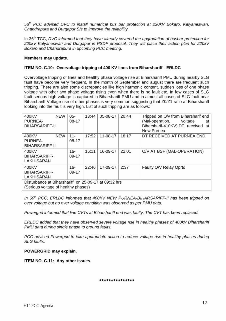
58th PCC advised DVC to install numerical bus bar protection at 220kV Bokaro, Kalyaneswari, Chandrapura and Durgapur S/s to improve the reliability. In 36th TCC, DVC informed that they have already covered the upgradation of busbar protection for 220kV Kalyaneswari and Durgapur in PSDF proposal. They will place their action plan for 220kV Bokaro and Chandrapura in upcoming PCC meeting. Members may update. ITEM NO. C.10: Overvoltage tripping of 400 KV lines from Biharshariff --ERLDC Overvoltage tripping of lines and healthy phase voltage rise at Biharshariff PMU during nearby SLG fault have become very frequent. In the month of September and august there are frequent such tripping. There are also some discrepancies like high harmonic content, sudden loss of one phase voltage with other two phase voltage rising even when there is no fault etc. In few cases of SLG fault serious high voltage is captured in Biharshariff PMU and in almost all cases of SLG fault near Biharshariff Voltage rise of other phases is very common suggesting that Z0/Z1 ratio at Biharshariff looking into the fault is very high. List of such tripping are as follows: 400KV NEW PURNEA-BIHARSARIFF-II
05-08-17
13:44 05-08-17 20:44 Tripped on O/v from Biharsharif end (Mal-operation, voltage at Biharsharif-410KV).DT received at New Purnea
400KV NEW PURNEA-BIHARSARIFF-II
11-08-17
17:52 11-08-17 18:17 DT RECEIVED AT PURNEA END
400KV BIHARSARIFF-LAKHISARAI-II
16-09-17
16:11 16-09-17 22:01 O/V AT BSF (MAL-OPERATION)
400KV BIHARSARIFF-LAKHISARAI-II
16-09-17
22:46 17-09-17 2:37 Faulty O/V Relay Oprtd
Disturbance at Biharshariff on 25-09-17 at 09:32 hrs (Serious voltage of healthy phases) In 60th PCC, ERLDC informed that 400KV NEW PURNEA-BIHARSARIFF-II has been tripped on over voltage but no over voltage condition was observed as per PMU data. Powergrid informed that line CVTs at Biharshariff end was faulty. The CVT has been replaced. ERLDC added that they have observed severe voltage rise in healthy phases of 400kV Biharshariff PMU data during single phase to ground faults. PCC advised Powergrid to take appropriate action to reduce voltage rise in healthy phases during SLG faults.
POWERGRID may explain.
ITEM NO. C.11: Any other issues.
***************
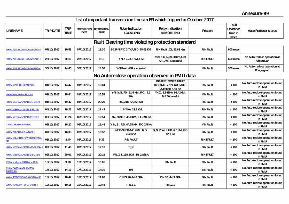
Annexure-B9
LINE NAME TRIP DATETRIP TIME
RESTORATION DATE
RESTORATION TIME
Relay Indication LOCAL END
Relay Indication REMOTE END
Reason
Fault Clearance
time in msec
Auto Recloser status
400KV ALIPURDUAR-BONGAIGAON-II 07/10/2017 10:59 07/10/2017 11:30 Z-2,R-N,F/C=3.7KA,F/D=78.09 KM R-N Fault , Z1, 37.63 Km R-N Fault 600 msec
400KV ALIPURDUAR-BONGAIGAON-I 28/10/2017 8:54 28/10/2017 9:13 R_N,Z-2,73.8 KM,4 KA zone 1,R_N,39.60 km,1.39
KA , A/R successfulR-N FAULT 600 msec
No Auto-reclose operation at Alipurduar
400KV ALIPURDUAR-BONGAIGAON-I 30/10/2017 14:45 30/10/2017 14:58 Y-N Fault,A/R successful Y-N Fault 300 msecNo Auto-reclose operation at
Bongaigaon
220KV MAITHON-DHANBAD-II 01/10/2017 14:47 01/10/2017 16:04R PHASE ,ZONE 1 FAULT
DISTANCE 77.24 KM FAULT CURRENT 4.45 kA
R-N Fault < 100No Auto-reclose operation found
in PMU
400KV RANCHI-ROURKELA-II 01/10/2017 16:44 01/10/2017 16:59Y-N fault. FD= 51.6 KM, F.C.= 5.3
KAYN,ZI, 3.548KA, 98.42KM,
A/R SuccessfulY-N Fault < 100
No Auto-reclose operation found in PMU
400KV MEERAMUNDALI-STERLITE-II 01/10/2017 19:47 01/10/2017 20:29 R-N,2.87 KA,168 KM R-N Fault < 100No Auto-reclose operation found
in PMU
400KV MEERAMUNDALI-STERLITE-I 04/10/2017 16:23 04/10/2017 17:43 Ir=6.3 KA, 23.8 KM. R-N Fault < 100No Auto-reclose operation found
in PMU
400KV MEERAMUNDALI-STERLITE-I 06/10/2017 11:24 06/10/2017 12:54 R-N, ZONE-1,46.0 KM, IL1-7.94 KA R-N Fault < 100No Auto-reclose operation found
in PMU
220KV CHUKHA-BIRPARA-I 06/10/2017 16:20 06/10/2017 16:46 Y_N, Z I, F.D. 44.78 KM, F.C. 2.5 kA Y-N Fault < 100No Auto-reclose operation found
in PMU
400KV ROURKELA-CHAIBASA-I 07/10/2017 16:33 07/10/2017 16:52Z-2,B-N,F/D-145.4KM, F/C-
2.434KAB_N, Zone I, F.D. 6.6 KM, F.C.
12.1 kAB-N Fault < 100
No Auto-reclose operation found in PMU
400KV KOLAGHAT-NEW CHANDITALA-SC 08/10/2017 8:40 08/10/2017 9:32 R-N FAULT R-N FAULT < 100
No Auto-reclose operation found in PMU
400KV MEERAMUNDALI-MENDHASAL-I 09/10/2017 11:49 09/10/2017 12:10 B_N B-N Fault < 100No Auto-reclose operation found
in PMU
400KV MEERAMUNDALI-STERLITE-II 09/10/2017 20:01 09/10/2017 20:19 RN, Z_I, 168.3KM , IR: 2.88KA R-N FAULT < 100No Auto-reclose operation found
in PMU
220KV Khalgaon BSEB-LALMATIA-I 15/10/2017 9:28 15/10/2017 10:05 R-N Fault R-N Fault < 100No Auto-reclose operation found
in PMU220KV DARBHANGA (DMTCL)-MOTIPUR-II 17/10/2017 14:19 17/10/2017 14:30 BN B-N Fault < 100
No Auto-reclose operation found in PMU
400KV JEERAT-NEW CHANDITALA-SC 18/10/2017 10:47 18/10/2017 11:08 C N Z1 26KM 6.6KA C,N 52 KM 3.9KA B-N Fault < 100No Auto-reclose operation found
in PMU
220KV TENUGHAT-BIHARSARIFF-I 19/10/2017 10:15 19/10/2017 10:45 R-N,Z-1 R-N,Z-1 R-N Fault < 100No Auto-reclose operation found
in PMU
No Autoreclose operation observed in PMU data
List of important transmission lines in ER which tripped in October-2017
Fault Clearing time violating protection standard

LINE NAME TRIP DATETRIP TIME
RESTORATION DATE
RESTORATION TIME
Relay Indication LOCAL END
Relay Indication REMOTE END
Reason
Fault Clearance
time in msec
Auto Recloser status
400KV MEERAMUNDALI-MENDHASAL-SC 21/10/2017 7:33 21/10/2017 18:34 B-N,24KM FC 8KA B-N Fault < 100
No Auto-reclose operation found in PMU
220KV FSTPP-LALMATIA-I 22/10/2017 12:58 22/10/2017 15:29 B_N CB CLOSED AT LALMATIA B-N Fault < 100No Auto-reclose operation found
in PMU
220KV JAYNAGAR-JEYPORE-I 23/10/2017 18:09 23/10/2017 23:05 CB CLOSED AT JAYNAGAR R_N,Z_1,12.32 KA,4.853 R-N Fault < 100No Auto-reclose operation found
in PMU
220KV RANCHI-HATIA-II 25/10/2017 10:08 25/10/2017 10:38 Z1,B-N, F/C-3.77KA, F/D-22KM Z1,B-N, F/D-24.18KM < 100No Auto-reclose operation found
in PMU
400KV MEERAMUNDALI-STERLITE-I 25/10/2017 13:21 25/10/2017 15:37 B-N,197 KM,2.55 KA B-N Fault < 100No Auto-reclose operation found
in PMU
220KV PATNA-KHAGAUL-SC 28/10/2017 12:23 28/10/2017 13:05 7.31 KA,9.91 KM,B_NZone-1, 18.83km, b_n,due to interference with bamboos.
B-N Fault < 100No Auto-reclose operation found
in PMU
220KV CHUKHA-BIRPARA-I 29/10/2017 0:03 29/10/2017 9:44B-N, Z-1, DIST 35.31KM , FC
3.248KA B-N fault < 100
No Auto-reclose operation found in PMU
400KV MEERAMUNDALI-STERLITE-I 29/10/2017 11:57 29/10/2017 17:46 b-n , z-1 , f/d-190 km,f/c-2.5 ka B-N fault < 100No Auto-reclose operation found
in PMU
400KV RANCHI-RAGHUNATHPUR-II 01/10/2017 16:44 01/10/2017 17:52 Did not tripped DT Recieved at RTPS end DT Recieved at RTPS end
400KV RANCHI-RAGHUNATHPUR-III 01/10/2017 16:44 01/10/2017 17:52 Did not tripped DT Recieved at RTPS end DT Recieved at RTPS end
400KV BIHARSARIFF-PUSAULI-I 04/10/2017 21:37 04/10/2017 22:33 Maloperation of O/V relayMaloperation of O/V relay at
Biharshariff
400KV PATNA-KISHANGANJ-II 06/10/2017 15:11 06/10/2017 16:17 DT received at PatnaO/V Relay mal-operrated at Kishanganj (Voltage around
411 KV)
O/V Relay mal-operrated at Kishanganj (Voltage around
411 KV)
400KV MAITHON-MAITHON RB-I 11/10/2017 11:14 11/10/2017 12:30Maloperation of protection
element at MaithonDid not tripped
Maloperation of protection element at Maithon
400KV JEYPORE-BOLANGIR-SC 16/10/2017 13:00 16/10/2017 13:18Opened from Bolangir end
onlyOpened from Bolangir end
only400KV BIHARSARIFF-BALIA-I 17/10/2017 10:56 17/10/2017 11:27 DT received at BSF DT received at BSF
400KV BOLANGIR-ANGUL-SC 20/10/2017 9:28 20/10/2017 11:10SPURIOUS DT SENT FROM
BOLANGIRSPURIOUS DT SENT FROM
BOLANGIR1500MVA ICT-1 AT ANGUL 20/10/2017 9:28 20/10/2017 14:16 SPURIOUS PRV OPERATED SPURIOUS PRV OPERATED
400KV MENDHASAL-PANDIABILI-I 21/10/2017 9:11 21/10/2017 10:43 CB opened from Mendhasal endCB opened from Mendhasal
end
220KV NEW PURNEA-MADHEPURA-II 30/10/2017 16:04 30/10/2017 16:14 TRIPPED FROM PURNEA END TRIPPED FROM PURNEA END
Miscellaneous: Tripping on DT, No reason furnished

Page | 1
ANNEXURE C1
1. Definitions of Protection System, its Philosophy and aspects related toProtection Coordination
1.1 Definitions: a) Act
The Electricity Act, 2003 as amended from time to time.
b) Auto recloserA circuit breaker equipped with a mechanism that can automatically close the breakerafter it has been opened due to a fault.
c) ContingencyThe unexpected failure or outage of a system component, such as a generator,transmission line, circuit breaker, switch or other electrical element.
d) Corrective Action PlanA list of actions and an associated timetable for implementation to remedy a specificproblem.
e) Central Transmission Utility (CTU)Any Government company, which the Central Government may notify under sub-section (1) of Section 38 of the Act;
f) Dead time of auto recloser relayThe time between the auto-reclose scheme being energized and the completion of thecircuit to the circuit breaker closing contactor.
g) Disturbance An unplanned event that produces an abnormal system condition. Any perturbation to the electric system. The unexpected change in Area Control Error (ACE) that is caused by the
sudden failure of generation or Interruption of load.
h) Disturbance Recorder (DR)A device provided to record the behaviour of the pre-selected digital and analogvalues of the system parameters during an Event.
i) EntityA Generating Company including captive generating plant or a transmission licenseeincluding Central Transmission Utility and State Transmission Utility or a distributionlicensee or a Bulk Consumer whose electrical plant is connected to the Grid at voltagelevel 33 kV and above.
j) Event Logger(EL)

Page | 2
A device provided to record the chronological sequence of operations, of the relays and other equipment.
k) Facility A set of electrical equipment that operates as a single Grid Element (e.g., a line, a generator, a shunt compensator, transformer, etc.)
l) Facility Rating
The maximum or minimum voltage, current, frequency, or real or reactive power flow through a facility that does not violate the applicable equipment rating of any equipment comprising the facility.
m) Generating Company Any company or body corporate or association or body of individuals, whether incorporated or not, or artificial juridical person, which owns or operates or maintains a generating station.
n) Grid The entire inter-connected electric power network of the country.
o) Grid disturbance
Tripping of one or more power system elements of the grid like a generator, transmission line, transformer, shunt reactor, series capacitor and Static VAR Compensator, resulting in total failure of supply at a sub-station or loss of integrity of the grid, at the level of transmission system at 220 kV and above (132 kV and above in the case of North-Eastern Region).
p) Grid incident Tripping of one or more power system elements of the grid like a generator, transmission line, transformer, shunt reactor, series capacitor and Static VAR Compensator, which requires re-scheduling of generation or load, without total loss of supply at a sub-station or loss of integrity of the grid at 220 kV and above (132 kV and above in the case of North-Eastern Region).
q) Grid Standards The standards specified by the Authority under clause (d) of the Section 73 of the Act.
r) Indian Electricity Grid Code (IEGC) or Grid Code These regulations specifying the philosophy and the responsibilities for planning and operation of Indian power system.
s) Interconnection A geographic area in which the operation of Bulk Power System components is synchronized such that the failure of one or more of such components may adversely affect the ability of the operators of other components within the system to maintain Reliable Operation of the Facilities within their control.

Page | 3
t) Inter State Transmission System (ISTS)
Any system for the conveyance of electricity by means of a main transmission line from the territory of one State to another State.
The conveyance of electricity across the territory of an intervening State as well as conveyance within the State which is incidental to such inter-state transmission of energy.
The transmission of electricity within the territory of State on a system built, owned, operated, maintained or controlled by CTU.
u) Load Blinder
Load blinders are the load encroachment elements used to block the distance relay when there is heavy load in the system to avoid cascading trips in the network.
v) NLDC
The Centre established under sub-section (1) of Section 26 of the Act.
w) Power System All aspects of generation, transmission, distribution and supply of electricity and includes one or more of the following, namely. generating stations; transmission or main transmission lines; sub-stations; tie-lines; load despatch activities; mains or distribution mains; electric supply lines; overhead lines; service lines; works.
x) Reactor
An electrical facility specifically designed to absorb Reactive Power.
y) Reclaim time of auto-reclose relay The time from the making of the closing contacts on the auto-reclose relay to the completion of another circuit within the auto-reclose scheme which will reset the scheme or lock out the scheme or circuit breaker as required.
z) Regional Power Committee (RPC) A Committee established by resolution by the Central Government for a specific region for facilitating the integrated operation of the power systems in that region.
aa) Regional Load Despatch Centre (RLDC) The Centre established under sub-section (1) of Section 27 of the Act.

Page | 4
bb) State Load Despatch Centre (SLDC) The Centre established under subsection (1) of Section 31 of the Act.
cc) Special Protection Scheme A scheme designed to detect predetermined System conditions and automatically take corrective actions that may include, but are not limited to, adjusting or tripping generation (MW and MVAR), tripping load, or reconfiguring a System(s).
dd) Stability Limit
The maximum power flow possible through some particular point in the system while maintaining stability in the entire system or the part of the system to which the stability limit refers.
ee) State Transmission Utility (STU) The Board or the Government Company specified as such by the State Government under sub-section (1) of Section 39 of the Act.
ff) Thermal Rating The maximum amount of electrical current that a transmission line or electrical facility can conduct over a specified time period before it sustains permanent damage by overheating or before it sags to the point that it violates public safety requirements.
gg) Transient stability The ability of the power system to maintain synchronism when subjected to a severe disturbance such as a short circuit on a transmission line.
hh) Transmission License
A License granted under Section 14 of the Act to transmit electricity.
ii) Transmission Planning Criteria The policy, standards and guidelines issued by the CEA for the planning and design of the Transmission system.
jj) Trickle/ Boost charging of battery Trickle charging means charging a fully charged battery under no-load at a rate equal to its self-discharge rate, thus enabling the battery to remain at its fully charged level. A battery under continuous float voltage charging is said to be under float-charging. Boost charging means charging a discharged battery at a high current for short period of time. Boost charge enables the quick charging of depleted batteries. Words and expressions used and not defined in these standards but defined in the Act shall have the meaning assigned to them in the Act.
1.2 General Philosophy of Protection System: There shall be protection philosophy which shall be prepared and adopted by each RPC in coordination with stakeholders in the concerned region in accordance with below mentioned objectives, design criteria and other details. However, protection design in a

Page | 5
particular system may vary depending upon judgment and experience in the broad contours of above protection philosophy. Consideration must also be given to the type of equipment to be protected as well as the importance of this equipment to the system. Further, protection must not be defeated by the failure of a single component:
1.2.1 Objectives: The basic objectives of any protection schemes should be to:
(i) Mitigate the effect of short circuit and other abnormal conditions in minimum possible time and area.
(ii) Indicate the location and type of fault and (iii)Provide effective tools to analyze the fault and decide remedial measures.
1.2.2 Design Criteria: To accomplish the above objectives, the four design criteria for
protection that should be considered are: (i) fault clearing time; (ii)selectivity; (iii)sensitivity and (iv) reliability (dependability and security).
1.2.2.1 Fault clearing time: In order to minimize the effect on customers and maintain system stability, fault clearing time shall be as per CEA Grid Standard Regulations 2010.
1.2.2.2 Selectivity: To ensure Selectivity, coordination shall be ensured with the adjacent protection schemes including breaker failure, transformer downstream relays, generator protection and station auxiliary protection.
1.2.2.3 Sensitivity: To ensure Sensitivity, the settings must be investigated to determine that they will perform correctly for the minimum fault current envisaged in the system, yet remain stable during transients and power swings from which the system can recover.
1.2.2.4 Reliability: To ensure Reliability, two independent auxiliary direct current-supplies shall be provided for Main-I and Main-II relays. The Main-I and Main-II relays should be from two different makes or operating with different algorithm. The CB´s shall have two independent trip coils and two independent trip circuits. Each protection device should trip at least one of them by independent auxiliary DC- supplies.
1.2.2.5 Security: To ensure Security, the protection shouldn’t limit the maximum transmission capacity of the element. Distance protection in particular could cause spurious tripping due to specific grid conditions, in case of high load operation. Therefore, any special topologies must be known and considered for protection parameterization. For parallel Over Head Lines it is necessary to consider the rapid increase of load current in the healthy line when the faulty line trips and the protection operation must allow such conditions The load encroachment detection function of the relays must be used, when the highest distance zone resistance reach conflicts with the maximum transmitted load on the protected element.
1.3 Philosophy of Line Protection:

Page | 6
Transmission circuit construction can be considered in three main categories viz.: Overhead construction, Underground cable construction and Composite (overhead plus underground) construction. The requirements of overhead line and cable protection systems vary greatly, due to the exposure of transmission circuits to a wide variety of environmental hazards and are subjected to the wide variations in the format, usage and construction methodologies of transmission circuits. The type of protection signaling (tele- protection) or data communication systems required to work with the protection systems will also influence protection scheme requirements.
Transmission circuit Main protection is required to provide primary protection for the line and clear all type of faults on it within shortest possible time with reliability, selectivity and sensitivity. Transmission circuit back-up protection shall cater for failure of any main protection system to clear any fault that it is expected to clear. A protection function that offers back-up for most faults may also provide main protection for some fault conditions. Combinations of main and back-up protection systems should be used to address the main and application specific requirements for transmission circuits.
1.3.1 Design Criterions: While designing the scheme for protection of transmission lines following criteria shall be included:
(i) The systems applied must be capable of detecting all types of faults, including maximum expected arc resistance that may occur at any location on the protected line.
(ii) The protection should be set not to trip under system transient conditions, which are not short circuits. Conversely where the short circuit current is low due to local grid conditions (weak network) or due to high resistance of the arc, this must be taken into consideration to trip the relay by using the most appropriate criterion, without jeopardizing the unwanted tripping during heavy load conditions. Protection relays must allow the maximum possible loadability of the protected equipment, while ensuring the clearing of anticipated faults according to the simulation studies.
(iii)The design and settings of the transmission line protection systems must be such that, with high probability, operation will not occur for faults external to the line or under non-fault conditions.
(iv) Settings related to the maximum possible loadability of the protected equipment shall be specified after a suitable load flow study and contingency analysis.
1.3.2 Reliability Criterions: A. For transmission line having voltages at 220kV and above: High speed
Duplicated Main Protection (Main-I and Main-II) shall be provided and at least one of them being carrier aided non-switched four zone distance protection. The other protection may be a phase segregated current differential (this may require digital communication) or a carrier aided non-switched distance protection.

Page | 7
Wherever Optical Ground Wire (OPGW) or separate optic fibre laid for the Communication is available, Main-I and Main-II protection shall be the line differential protection with distance protection as backup (builtin Main relay or standalone). For very short line (less than 10 km), line differential protection with distance protection as backup (built-in Main relay or standalone) shall be provided mandatorily as Main-I and Main-II.).
In addition to above, following shall also be provided: (i) Two stage over-voltage protection. However, in case of 220 kV lines, in cases
where system has grown sufficiently or in case of short lines, utilities on their discretion may decide not to provide this protection.
(ii) Auto reclose relay suitable for 1 ph or 3 ph (with deadline charging and synchro- check facility) reclosure.
(iii) Sensitive Inverse Definite Minimum Time (IDMT) directional E/F relay (standalone or as built-in function of Main-I & Main-II relay).
Main Protection shall have following features: a. The Main-I and Main-II protection shall be numerical relays of different
makes or employ different fault detection algorithm. b. Each distance relay shall protect four independent zones (three forward zones
and one reverse zone). It shall be provided with carrier aided tripping. c. The relays should have sufficient speed so that they will provide the clearing
times as defined in the latest revision of CEA Grid Standards Regulations. d. The Main-I and Main-II relays shall be powered by two separate DC source. e. Both, Main-I and Main-II shall send separate initiation signal to Breaker
Failure Relay. f. Internal Directional Earth Fault function shall be set to trip the line in case of
high resistance earth faults. g. The Broken Conductor detection shall be used for alarm purpose only. h. The internal overvoltage function shall be used to protect the line against over
voltages. The protection shall be set in two stages. The lines emanating from same substation shall be provided with pick-up as well as time grading to avoid concurrent trippings. The overvoltage relay shall have better than 97% drop-off to pick-up ratio (the ratio of the limiting values of the characteristic quantity at which the relay resets and operates).
B. For transmission line having voltages at 132kV: There should be at least one carrier aided non-switched four zone distance protection scheme. In addition to this, another non-switched/switched distance scheme or directional over current and earth fault relays should be provided as back up. Main protection should be suitable for single and three phase tripping. Additionally, auto-reclose relay suitable for 1 ph or3 ph (with dead line charging and synchro-check facility) reclosure shall be provided. In case of both line protections being Distance Protections, IDMT type Directional E/F relay (standalone or as built-in function of Main-I & Main-II relay) shall also be provided additionally.

Page | 8
1.3.3 Following types of protection scheme may be adopted to deal with faults on the lines:
1.3.3.1. Distance Protection scheme: The scheme shall be based on the measuring
the impedance parameters of the lines with basic requirements as below: a. Each distance relay shall protect four independent zones (three forward
zones and one reverse zone). It shall be provided with carrier aided tripping.
b.Each Distance Relay: i. Shall include power swing detection feature for selectively blocking, as
required. ii. Shall include suitable fuse-failure protection to monitor all types of fuse
failure and block the protection. iii. Shall include load encroachment prevention feature like Load blinder. iv. Shall include Out of Step trip function. v. Distance relay as Main protection should always be complemented by
Directional ground protection to provide protection for high resistive line faults.
vi. Shall be capable to protect the series compensated lines from voltage inversion, current inversion phenomenon. Special measures must be taken to guard against these phenomenon.
1.3.3.2 Line Differential Protection: The scheme shall be based on the comparing the electrical quantities between input and output of the protected system. Provided that:
(a) Due to the fact that short lines and/or cables do not have enough electrical length, the current differential relay should always be used.
(b) For Cables, at least a differential line protection shall be used in order to guarantee fast fault clearing while maintaining security. The reason being that there are many sources of errors associated to other protection principles, especially for ground faults in cables.
The differential protection shall have following requirements:
(i) Line differential as Main-I with inbuilt Distance Protection shall be installed for all the lines irrespective of length (subject to technical limitations). The inbuilt distance protection feature shall get automatically enabled in case of communication failure observed by the differential relay.
(ii) The differential relays provided in 220kV and above system must operate in less than 30 ms.
(iii)The current differential protection should a reliable type (preferably digital). The protection should be of the segregate phase type, i.e. it should be able to detect the phase in fault and therefore for the case of single line-ground (SLG) faults to trip only the phase in fault (also to establish single phase A/R). The synchronization of the measured values

Page | 9
is done via a communication system. The communication system for differential line protection should be based on fiber optic and any equipment should comply with the IEC 60834.
1.3.4. Auto Reclosing:
The single phase high speed auto-reclosure (HSAR) at 220 kV level and above shall be implemented, including on lines emanating from generating stations. If 3-phase autoreclosure is adopted in the application of the same on lines emanating from generating stations should be studied and decision taken on case to case basis by respective RPC.
1.3.4.1 AR Function Requirements: It shall have the following attributes: (i) Have single phase or three phase reclosing facilities. (ii) Have a continuously variable single phase dead time. (iii) Have continuously variable three phase dead time for three phase reclosing. (iv) Have continuously variable reclaim time. (v) Incorporate a facility of selecting single phase/three phase/single and three
phase auto-reclose and non-auto reclosure modes. (vi) Have facilities for selecting check synchronizing or dead line charging features. (vii) Be of high speed single shot type (viii) Suitable relays for SC and DLC should be included in the overall auto-reclose
scheme if three phase reclosing is provided. (ix) Should allow sequential reclosing of breakers in one and half breaker or double
breaker arrangement.
1.3.4.2. Scheme Special Requirements: (i) Modern numerical relays (IEDs) have AR function as built-in feature. However,
it is recommended to use standalone AR relay or AR function of Bay control unit (BCU) for 220kV and above voltage lines. For 132kV lines, AR functions built-in Main distance relay IED can be used.
(ii) Fast simultaneous tripping of the breakers at both ends of a faulty line is essential for successful auto-reclosing. Therefore, availability of protection signaling equipment is a pre-requisite.
(iii)Starting and Blocking of Auto-reclose Relays: Some protections start auto-reclosing and others block. Protections which start A/R are Main-I and Main-II line protections. Protections which block A/R are:
a. Breaker Fail Relay b. Line Reactor Protections c. O/V Protection d. Received Direct Transfer trip signals e. Busbar Protection f. Zone 2/3 of Distance Protection g. Carrier Fail Conditions h. Circuit Breaker Problems.

Page | 10
i. Phase to Phase Distance Trip When a reclosing relay receives start and block A/R impulse simultaneously, block signal dominates. Similarly, if it receives ‘start’ for 1-phase fault immediately followed by multi- phase fault the later one dominates over the previous one.
1.3.4.3 Requirement for Multi breaker Arrangement: Following schemes shall be adhered to multi-breaker arrangements of one and half breaker or double breaker arrangement:
(i) In a multi-Circuit Breaker (C.B.) arrangement one C.B. can be taken out of operation and the line still be kept in service. After a line fault only those C.Bs which were closed before the fault shall be reclosed.
(ii) In multi-C.B. arrangement it is desirable to have a priority arrangement so as to avoid closing of both the breakers in case of a permanent fault.
(iii)A natural priority is that the C.B. near the busbar is reclosed first. In case of faults on two lines on both sides of a tie C.B. the tie C.B. is reclosed after the outer C.Bs. The outer C.Bs. do not need a prioritizing with respect to each other.
(iv)In case of bus bar configuration arrangement having a transfer breaker, a separate auto- reclosure relay for transfer breaker is recommended.
1.3.4.4 Setting Criteria:
(i) Auto reclosing requires a dead time which exceeds the de-ionising time. The circuit voltage is the factor having the predominating influence on the de-ionising time. Single phase dead time of 1.0 sec. is recommended for 765 kV, 400 kV and 220 kV system. For the lines emanating from generating stations single-phase dead time upto 1.5 sec may be adopted.
(ii) According to IEC 62271-101, a breaker must be capable of withstanding the following operating cycle with full rated breaking current:
O - 0.3 s - CO - 3 min - CO
The recommended operating cycle at 765kV, 400 kV and 220 kV is as per the IEC standard. Therefore, reclaim time of 25 Sec. is recommended.
1.3.5. Power Swing Blocking and Out of Step (OOS) Function
Large interconnected systems are more susceptible to Power Swings in comparison to the erstwhile smaller standalone systems. Inter-area Power Swings can be set up even due to some event in far flung locations in the system. During the tenure of such swings, outage of any system element may aggravate the situation and can lead to instability (loss of synchronism). It is hence extremely important that unwanted tripping of transmission elements need to be prevented, under these conditions. Distance protection relays demand special consideration under such a situation, being susceptible to undesirable mis-operation during Power swings which may be recoverable or irrecoverable power swings. Following steps may be adopted to achieve above objective:

Page | 11
A. Block all Zones except Zone-I
This application applies a blocking signal to the higher impedance zones of distance relay and allows Zone 1 to trip if the swing enters its operating characteristic. Breaker application is also a consideration when tripping during a power swing. A subset of this application is to block the Zone 2 and higher impedance zones for a preset time (Unblock time delay) and allow a trip if the detection relays do not reset. In this application, if the swing enters Zone 1, a trip is issued, assuming that the swing impedance entering the Zone-1 characteristic is indicative of loss of synchronism. However, a major disadvantage associated with this philosophy is that indiscriminate line tripping can take place, even for recoverable power swings and risk of damage to breaker.
B. Block All Zones and Trip with Out of Step (OOS) Function
This application applies a blocking signal to all distance relay zones and order tripping if the power swing is unstable using the OOS function (function built in modern distance relays or as a standalone relay). This application is the recommended approach since a controlled separation of the power system can be achieved at preselected network locations. Tripping after the swing is well past the 180-degree position is the recommended option from CB operation point of view. Normally relay is having Power Swing Un-block timer which unblocks on very slow power swing condition (when impedance locus stays within a zone for a long duration). Typically, the Power swing un-blocking time setting is 2sec. However, on detection of a line fault, the relay has to be de-blocked.
C. Placement of OOS trip Systems Out of step tripping protection (Standalone relay or built-in function of Main relay) shall be provided on all the selected lines. The locations where it is desired to split the system on out of step condition shall be decided based on system studies. The selection of network locations for placement of OOS systems can best be obtained through transient stability studies covering many possible operating conditions. Based on these system studies, either of the option above may be adopted after the approval of Appropriate Sub-Committee of RPC.
While applying Power Swing Blocking (PSB) in the distance protection relay a few other important aspects also needs to be considered. PSB function should not block if negative sequence or zero sequence currents are
present. Once blocked, the PSB should unblock if negative sequence or zero sequence currents are detected. Power Swing is a balanced three phase phenomenon and unbalance can only occur in the case of an asymmetrical fault.
It will be desirable that during tenure of PSB, the distance protection is capable of detecting a fault and tripping. If such a feature is not available in the relay, PSB should be unblocked after a time delay, corresponding to the half cycle period of the slowest expected Swing Frequency (usually 2s corresponding to the slowest swing frequency of 0.25Hz is considered as default), to avoid the protection remaining perpetually blocked.

Page | 12
1.4 Protection Coordination: A protection-coordination study shall be done to determine the trip settings of each protective device in the power system so that maximum protection with minimum interruption is provided for all faults that may happen in the system. System studies shall be conducted using computer- aided tools to assess the security of protection by finding out trajectory of impedance in various zones of distance relay under abnormal or emergency system condition on case-to-case basis particularly for critical lines / corridors.
Relay coordination calculation module must consider the operating characteristics of the relays, normal operating and thermal or mechanical withstand characteristics of the equipment and must determine the optimum relay settings to achieve the protection objectives stated under Para 1.2.1. In addition, the settings must be fine-tuned, simulating faults using Real Time Digital Simulator on case-to-case basis particularly for critical lines / corridors.
Part 1 (Requirements)
The purpose is to ensure system protection is coordinated among operating entities. The Protection coordination requirement shall include the following:
(1) Each Transmission Licensee, Load Dispatch Centre (LDC) and Generator Company shall keep themselves familiarized with the purpose and limitations of Protection System schemes applied in its area of control.
(2) Each Transmission licensee shall coordinate its Protection System schemes with concerned transmission system, sub-transmission system and generators.
(3) Each Generating Company shall coordinate its Protection System schemes with concerned transmission system and station auxiliaries.
(4) Each Transmission Licensee and Generation Company shall be responsible for settings calculations for protection of elements under its ownership. It shall be the responsibility of the respective asset owner to obtain the inputs (adjacent line settings, infeed values etc.) from CTU/STU/RPC necessary for calculation of the settings.
(5) CTU/STU shall provide the infeed values/latest network model to the requesting entity, within 15 days of receipt of such a request from the entity. The RPC shall provide the existing settings of the adjacent substations within 15 days of such a request from the requesting entity.
(6) Each Generating Company and Transmission Licensee shall submit the protection settings along with the calculation sheets, co-ordination study reports and input data, in advance, to respective RPC for every new element to be commissioned. The mentioned information shall be submitted to the RPC by first week of each month for all the elements proposed to be commissioned in the following month.
(7) The appropriate sub-committee of RPC shall review the settings to ensure that they are properly coordinated with adjacent system and comply with the existing guidelines. The onus to prove the correctness of the calculated settings shall lie with the respective Transmission licensee/Generation Company. In case, the sub-committee feels that the adjacent transmission system settings need to be changed, in view of the new element, it shall inform the concerned entity for revision of the existing settings.
Page | 13
(8) If the RPC feels the need, it may recommend carrying out the dynamic study for the concerned system to ensure that the present settings are sufficient for maintaining the dynamic stability of the system. In such a case, on being directed by RPC, the respective CTU/STU shall carry out the necessary dynamic studies and submit the report to the RPC.
(9) The appropriate sub-committee of RPC shall review and approve the settings based on the inputs/report submitted by the entities.
(10) The approved settings shall be implemented by the entity and proper record of the implemented settings shall be kept. The modern numerical relays have several settings for various features available in the relay. It shall be ensured that only the approved features and settings are enabled in the relay. No additional protection/setting shall be enabled without the prior approval by respective RPC.
(11) Each Transmission licensee and Generation Company shall co-ordinate the protection of its station auxiliaries to ensure that the auxiliaries are not interrupted during transient voltage decay.
(12) Any change in the existing protection settings shall be carried out only after prior approval from the RPC. The owner entity shall inform all the adjacent entities about the change being carried out.
(13) In case of failure of a protective relay or equipment failure, the Generator Company and Transmission Licensee shall inform appropriate LDC. The Generator Company and Transmission Licensee shall take corrective action as soon as possible.
(14) Each Transmission Licensee shall coordinate Protection Systems on major transmission lines and interconnections with neighboring Generator Company, Transmission Licensee, and appropriate LDC.
(15) Each Transmission Licensee, Generator Company and Distribution Licensee shall monitor the status of each System Protection Scheme in their area, and shall inform to concerned RLDC about each change in status.
Part 2 (Measures of Compliance)
The measures to be done for Protection coordination are as follows: (1) Each Generator Company and Transmission Licensee shall have and provide upon
request evidence that could include but is not limited to, revised fault analysis study, protection relay settings, notifications of changes, or other equivalent evidence that will be used to confirm that there was coordination of their Protection System, new Protection System or changes in it.
(2) Each Transmission Licensee, Generator Company and Distributor shall have and provide upon request evidence that could include but is not limited to, documentation, electronic logs, computer printouts, or computer demonstration or other equivalent evidence that will be used to confirm that it monitors the System Protection Schemes in its area confirm and that it informed to concerned RLDC about changes in status of one of its System Protection Schemes.
2. Disturbance Monitoring and Reporting

Page | 14
The Purpose is to ensure that adequate disturbance data is available to facilitate Grid event analysis. The analysis of power system disturbances is an important function that monitors the performance of protection system, which can provide information related to correct behavior of the system, adoption of safe operating limits, isolation of incipient faults, The Disturbance Monitoring Requirements Shall include the following: (1) Each Transmission Licensee and Generator Company shall provide Sequence of
Event (SOE) recording capability by installing Sequence of Event recorders or as part of another device, such as a Supervisory Control and Data Acquisition (SCADA) Remote Terminal Unit (RTU), a generator plants Digital (or Distributed) Control System (DCS) or part of Fault recording equipment. This capability shall be provided at all substations and at locations to record all the events in accordance with CEA Grid Standard Regulation, 2010. The following shall also be monitored at each location:
1.1.1 Transmission and Generator circuit breaker positions 1.1.2 Protective Relay tripping for all Protection Groups that operate to trip
circuit breakers identified in 1.1.1. 1.1.3 Tele protection keying and receive
(2) In either case, a separate work station PC shall be identified to function as the event logger front end. The event logger work-station PC should be connected to UPS (Uninterrupted Power Supply). The event logger signals shall include but not limited to
All Circuit Breaker and isolator switching Operations Auxiliary supply (AC, DC and DG) supervision alarms Auxiliary supply switching signals Fire-fighting system operation alarms Operation signals (Alarm/Trip from all the protection relays.) Communication Channel Supervision Signals. Intertrip signals receipt and send. Global Positioning System (GPS) Clock healthiness. Control Switching Device healthiness (if applicable). RTU/Gateway PC healthiness All Circuit Breaker Supervision Signals. Trip Circuit Supervision Signals.
(3) Each Transmission Licensee shall provide Disturbance recording capability for the following Elements at facilities: 3.1 All transmission lines. 3.2 Autotransformers or phase-shifters connected to busses. 3.3 Shunt capacitors, shunt reactors. 3.4 Individual generator line interconnections. 3.5 Dynamic VAR Devices. 3.6 HVDC terminals. 3.7 Bus Bars
(4) The Disturbance recording feature shall be enabled and configured in all the numerical relays installed.

Page | 15
(5) Each Generator Company shall provide Disturbance recording capability for Generating Plants in accordance with the CEA Technical Standards for Connectivity and CEA Technical Standards for Construction of Plants.
(6) Each Transmission Licensee and Generator Company shall record for Faults, sufficient electrical quantities for each monitored Element to determine the following: 6.1 Three phase-to-neutral voltages. (Common bus-side voltages may be used for
lines.) 6.2 Three phase currents and neutral currents. 6.3 Polarizing currents and voltages, if used. 6.4 Frequency. 6.5 Real and reactive power. The Minimum parameters to be monitored in the Fault record shall be specified by the respective RPC.
(7) Each Transmission Licensee and Generator Company shall provide Disturbance recording with the following capabilities: 7.1 The data files shall be capable of being viewed, read, and analyzed with a
generic COMTRADE analysis tool as per the latest revision of IEEE Standard C37.111.
7.2 Each Fault record duration and the trigger timing shall be settable and set for a minimum 2 second duration including 300ms pre-fault time.
7.3 Each Fault recorder shall have a minimum recording rate of 64 samples per cycle.
7.4 Each Fault recorder shall be set to trigger for at least the following: Internal protection trip signals, external trigger input, analog triggering (any phase current exceeding 1.5 pu of CT secondary current or any phase voltage below 0.8pu, neutral/residual overcurrent greater than 0.25pu of CT secondary current). Additional triggers may be assigned as necessary.
(8) Each Transmission Licensee and Generator Company shall establish a maintenance and testing program for Disturbance Recorder (DR) that includes 8.1 Maintenance and testing intervals and their basis. 8.2 Summary of maintenance and testing procedures. 8.3 Monthly verification of communication channels used for accessing records
remotely (if the entity relies on remote access and the channel is not monitored to a control center staffed around the clock, 24 hours a day, 7 days a week (24/7)).
8.4 Monthly verification of time synchronization (if the loss of time synchronization is not monitored to a 24/7 control center).
8.5 Monthly verification of active analog quantities. 8.6 A requirement to return failed units to service within 90 days. If a
Disturbance Recorder (DR) will be out of service for greater than 90 days, the Transmission Licensee and Generator Company shall keep a record of efforts aimed at restoring the DR to service.
(9) Each LDC, Transmission Licensee and Generator Company shall share requisite data within 15 days upon request. Each LDC, Transmission Licensee and Generator Company shall provide appropriate recorded disturbance data from DRs within 15 days of receipt of the request in each of the following cases:

Page | 16
9.1 CEA, RPCs/State, other LDC. 9.2 Request from other Transmission Licensee and Generator Company
connected with Inter State Transmission System (ISTS). (10) Each Transmission Licensee and Generator Company shall submit the data files to
the appropriate RLDC conforming to the following format requirements: 10.1 The data files shall be submitted in COMTRADE and PDF format. 10.2 File shall have contained the name of the Relay, name of the Bay, station
name, date, time resolved to milliseconds, event point name, status. The DR archives shall be retained for a period of three years.
(11) A separate work-station PC, powered through UPS (Uninterrupted Power Supply) shall be identified with access to all the relays for extraction of DR. Auto-Download facility shall be established for automatic extraction of the DR files to a location on the work- station PC.
(12) Time Sync Equipment 12.1 Each substation shall have time synch equipment to synchronize all the
numerical relays installed. Before any extension work, the capability of the existing Time-sync equipment shall be reviewed to ensure the synchronization of upcoming numerical relays.
12.2 The status of healthiness of the time-sync device shall be wired as “Alarm” to SCADA and as an “Event” to Event Logger.
12.3 The time synch status of all the installed numerical relays and event logger shall be monitored monthly and recorded. The Monthly records for relays not in time-sync shall be reported to appropriate RLDC and RPC. This record shall be archived for a period of three years by each concerned agency.
(13) Disturbance Analysis and Reporting 13.1 Subsequent to every tripping event, the concerned utility shall submit all the
relevant DR files in COMTRADE and PDF format along with SOE, to the appropriate Load Dispatch Centre, regional power committee, Remote End Entity and the entity connected to the downstream of transformers (in case of transformer tripping).
13.2 Each utility shall develop internal procedure of disturbance analysis. Necessary software shall be available with the entities to view and analyse the fault record files in COMTRADE and PDF format. The detailed analysis report shall identify the reason of fault, detailed sequence of events, mis-operations identified (if any), reason of protection mis- operation and corrective actions taken. Every entity shall submit the detailed analysis report within one week of the date of event occurrence, to the appropriate load dispatch center.
13.3 A monthly report shall be prepared by each utility, mentioning the events of protection misoperations whose reasons could not be identified and require further follow-up. This report for each month shall be submitted to RPC and RLDC within the first week of the subsequent month.
13.4 The detailed analysis reports shall be archived periodically. The archive shall be retained for a period of three years by each concerned agency.
13.5 The analysis reports shall be discussed in the Appropriate Sub-Committee meetings of the RPC to be held periodically. The Appropriate Sub-Committee shall identify the lessons learnt during the events being discussed.

Page | 17
The Appropriate Sub-Committee shall scrutinize the correctness of operation of subject protection systems put in place by the concerned Constituents. It shall also recommend the appropriate remedial measures for system improvement.
13.6 Each RPC/RLDC shall develop and maintain a web based portal to act as a data repository with the facility for utilities to upload the fault records, analysis reports and protection relay settings.
3. Protection System Misoperation Reporting and Monitoring of
Corrective Action: (1) Definition of Misoperation: 1. Any failure of a Protection System element to operate within the specified time when a
fault or abnormal condition occurs within a zone of protection. 2. Any operation of a Protection System for a fault not within a zone of protection (other
than operation as backup protection for a fault in an adjacent zone that is not cleared within a specified time for the protection for that zone).
3. Any unintentional Protection System operation when no fault or other abnormal condition has occurred unrelated to on-site maintenance and testing activity.
(2) Objectives: 1. Review all Protection System operations to identify the misoperations of Protection
Systems. 2. Analyze misoperations of Protection Systems to identify the cause(s). 3. Develop and implement Corrective Action Plans to address the cause(s) of
misoperations of Protection Systems. 4. Monitoring of implementation of corrective action plans.
(3) Requirements 1. Each Transmission Licensee, Generator Company, and Distribution Licensee that owns
interrupting device that operated under the circumstances in Parts 1.1 through 1.3 shall, within 24 hours of the interrupting device operation, identify and report to respective SLDC/RLDC or NLDC whether its Protection System component(s) caused a Misoperation. 1.1 The interrupting device operation was caused by a Protection System or by manual
intervention in response to a Protection System failure to operate; and 1.2 The interrupting device owner owns all or part of the Protection System; and 1.3 The interrupting device owner identified that its Protection System component(s)
caused the interrupting device(s) operation or was caused by manual intervention in response to its Protection System failure to operate.
2. When Protection System is shared among two or more utilities, each Transmission Licensee, Generator Company, and Distribution Licensee that owns an interrupting device that operated by protection system or by manual intervention in response to a protection system failure to operate, shall, within 24 hours of the interrupting device operation, provide information to the other utilities as well as respective SLDC/RLDC

Page | 18
or NLDC that share Misoperation identification responsibility for the Protection System under the following circumstances: 2.1 The interrupting device owner has determined that a Misoperation occurred or
cannot rule out a Misoperation; and 2.2 The interrupting device owner has determined that its Protection System
component(s) did not cause the interrupting device(s) operation or cannot determine whether its Protection System components caused the interrupting device(s) operation.
For an interrupting device operation by a Protection System component intended to operate as backup protection for a condition on another entity’s Power System Element, information of the operation shall be provided to the other Protection System utilities for which that backup protection was provided.
3. Each Transmission Licensee, Generator Company, and Distribution Licensee that receives information, pursuant to Requirement 2 shall, within 48 hours of the interrupting device(s) operation, identify whether its Protection System component(s) caused a Misoperation.
4. Each Transmission Licensee, Generator Company, and Distribution Licensee that has not determined the cause(s) of a Misoperation, for a Misoperation identified in accordance with Requirement 1 or 3, shall perform investigative action(s) to determine the cause(s) of the Misoperation at least once in a month after the Misoperation was first identified, until one of the following completes the investigation. The duration of investigation shall not be more than 3 months from the date of misoperation. The identification of the cause(s) of the Misoperation; or A declaration that the operation is not misoperation.
5. Each Transmission Licensee, Generator Company, and Distribution Licensee that owns the Protection System component(s) that caused the Misoperation shall, within one month of first identifying a cause of the Misoperation: Develop a Corrective Action Plan (CAP) along with the root cause analysis/
investigation report for the identified Protection System component(s), and an evaluation of the CAP’s applicability to the entity’s other Protection Systems including other locations and submit the same to RPCs; or
Explain in a declaration why corrective actions are beyond the entity’s control or would not improve Grid reliability, and that no further corrective actions will be taken.
6. Each Transmission Licensee, Generator Company, and Distribution Licensee shall implement each CAP developed in Requirement 5, and update each CAP if actions or timetables change, until completed.
7. RPCs shall deliberate the reported misoperation in Appropriate Sub- Committee meetings and monitor the implementation of CAP.
(4) Measures of Compliance: Each Transmission Licensee, Generator Company, and Distribution Licensee shall have dated evidence that demonstrates the followings: 1. It identified and reported the Misoperation of its Protection System component(s), if
any, that meet the circumstances in Requirement 1 within the allotted time period. 2. It informed to the other owner(s), within the allotted time period for Requirement 2.

Page | 19
3. It identified whether its Protection System component(s) caused a Misoperation within the allotted time period for Requirement 3.
4. It performed at least one investigative action according to Requirement 4 at least once in a month until a cause is identified or a declaration is made. Acceptable evidence for Requirement 1,2,3 & 4 may include, but is not limited to the following dated documentation (electronic or hardcopy format): reports, databases, spreadsheets, emails, facsimiles, lists, logs, records, declarations, analyses of sequence of events, relay targets, Disturbance Recorder (DR) and Event Logger (EL) records, test results, or transmittals.
5. It developed a CAP and an evaluation of the CAP’s applicability to other Protection Systems and locations, or a declaration in accordance with Requirement 5. Acceptable evidence may include, but is not limited to the following dated documentation (electronic or hardcopy format): CAP and evaluation, or declaration.
6. It implemented each CAP, including updating actions or timetables. Acceptable evidence may include, but is not limited to the following dated documentation (electronic or hardcopy format): records that document the implementation of each CAP and the completion of actions for each CAP including revision history of each CAP. Evidence may also include work management program records, work orders, and maintenance records.
7. RPCs shall maintain the updates of implementation of CAP.
4. Monitoring of System Protection Scheme (SPS) Misoperation: (1) Definition of SPS Misoperation: SPS misoperations are defined as follows: 1. Failure to Operate – Any failure of a SPS to perform its intended function within the
designed time when system conditions intended to trigger the SPS occurs; 2. Failure to Arm – Any failure of a SPS to automatically arm itself for system conditions
that are intended to result in the SPS being automatically armed; 3. Unnecessary Operation – Any operation of a SPS that occurs without the occurrence of
the intended system trigger condition(s); 4. Unnecessary Arming – Any automatic arming of a SPS that occurs without the
occurrence of the intended arming system condition(s); and 5. Failure to Reset – Any failure of a SPS to automatically reset following a return of
normal system conditions if that is the system design intent. (2) Objectives: 1. Reporting of all System Protection Scheme (SPS) Misoperations 2. Analysis of all System Protection Scheme (SPS) Misoperations and/or 3. Mitigation of all System Protection Scheme (SPS) Misoperations.
(3) Requirements: 1.System Operational Personnel and System Protection personnel of the Transmission
Licensee and Generator Company shall analyze all SPS operations.

Page | 20
1.1. System Operational Personnel and System Protection Personnel shall report and review all SPS operations to RPCs/RLDCs/NLDC to identify apparent Misoperations within 24 hours.
1.2. System Protection Personnel shall analyze all operations of SPS within seven working days for correctness to characterize whether a Misoperation has occurred that may not have been identified by them.
2.Transmission Licensee and Generator Company shall perform the following actions for each Misoperation of the SPS. If SPS actions that appear to be entirely reasonable and correct at the time of occurrence and associated system performance is fully compliant with IEGC/ CEA Standards the following requirements shall not be applicable. If the Transmission Licensee or Generator Company later finds the SPS operation to be incorrect through their analysis, the following requirements become applicable at the time the Transmission Licensee or Generator Company identifies the Misoperation: 2.1. If there is an SPS Misoperation Transmission Licensee and Generator Company
shall repair and place back in service within 24 hours the SPS that misoperated. If this cannot be done, then 2.1.1 Transmission Licensee and Generator Company shall report to respective
SLDC/RLDC or NLDC for necessary action to adjust generation and line flows to a reliable operating level.
2.1.2 SLDC/RLDC/NLDC shall give instructions to concerned utilities to operate the facilities within permissible limits.
2.1.3 Transmission Licensee and Generator Company shall perform the instructions of SLDC/RLDC/NLDC as soon as they received and report back to respective SLDC/RLDC or NLDC for the implementation of the same.
3.Transmission Licensee and Generator Company shall submit Misoperation incident reports to NLDC/RLDCs/RPCs within seven working days for the following.
3.1. Identification of a Misoperation of a SPS, 3.2. Completion of repairs or the replacement of SPS that misoperated.
4.SPS shall be reviewed at least once in a year or whenever any change in network/ modification.
(4) Measures of Compliance: 1. System Operational Personnel and System Protection personnel of the Transmission
Licensee and Generator Company shall have evidence that they reported and analyzed all SPS operations. 1.1 Transmission Licensee and Generator Company shall have evidence that they
reviewed all operations of SPS within 24 hours. 1.2 Transmission Licensee and Generator Company shall have evidence that they
analyzed all operations of SPS for correctness within seven working days. 2. Transmission Licensee and Generator Company shall have evidence that they have
repaired and replaced the SPS that misoperated from service within 24 hours following identification of the SPS Misoperation. 2.1 The Generator Company and Transmission Licensee shall have documentation describing all actions in accordance with Requirements 2.1.1 and 2.1.3.SLDC/RLDC/NLDC shall have the evidence in accordance with the Requirements 2.1.2.

Page | 21
3. Transmission Licensee and Generator Company shall have evidence that they reported to
NLDC/RLDCs/RPCs about the following within seven working days. 3.1 Identification of all SPS Misoperations and corrective actions taken or planned. 3.2 Completion of repair, replacement of, or SPS that misoperated.
4. Transmission Licensee and Generator Company shall have evidence that they reviewed SPS at least once in a year or whenever any change in network/ modification.
5. Transmission and Generation Protection System Maintenance and Testing
(1) Definitions: 1. Protection System: The Protection System includes Protection relays, associated
communication system, System Protection Schemes, voltage and current sensing devices, DC control circuit, battery, circuit breakers & associated Trip Circuits etc. Protection relays shall also include Under Frequency Relays and Under Voltage Relays.
2. Maintenance: An ongoing program by which Protection System function is proved, and restored if needed. A maintenance program comprises verification of individual protection systems, which in turn is achieved by of a combination of monitoring, testing, and calibration.
3. Testing: Application of signals to a Protection System or component removed from service, to observe functional performance or output behavior.
(2) Objective: To ensure all transmission and generation Protection Systems affecting the Grid reliability are maintained and tested.
(3) Requirements: 1. Each Transmission Licensee and each Generator Company that owns a generator
interconnection Facility Protection System shall have a Protection System maintenance and testing program for Protection Systems that connected to Grid. The program shall include: 1.1. Preventive maintenance and testing intervals and their basis. 1.2. Summary of maintenance and testing procedures. 1.3. Responsibilities of concerned wings of Licensee
2. Each Transmission Licensee and each Generator Company that owns a generator interconnection Facility Protection System shall provide documentation of its Protection System maintenance and testing program and the implementation of that program to the concerned RPCs as per the Table A. The documentation of the program implementation shall include: 2.1. Evidence of Protection System devices were maintained and tested within the
defined intervals. 2.2. Date of each Protection System device was last tested/maintained.

Page | 22
(4) Measures of Compliance: 1. Each Transmission Licensee and each Generator Company that owns a generator
interconnection Facility Protection System that affects the Grid reliability, shall have an associated Protection System maintenance and testing program as defined in Requirement 1.
2. Each Transmission Licensee and each Generator Company that owns a generator interconnection Facility Protection System that affects the Grid reliability, shall have evidence it provided documentation of its associated Protection System maintenance and testing program and the implementation of its program as defined in Requirement 2.
3. Retention of Records: The verification records for a particular protection system or component should be retained at least until successful completion should be retained for at least three years.
TABLE A- Maximum Allowable Testing Intervals by Equipment Category
Category Component Maximum verification interval
Verification Activities
Unmonito red
Monitored
1. Testing and calibration of protective relays.
3 years Continuous monitoring and verification
Test the functioning of relays with simulated inputs, including calibration. Verify that settings are as specified.
2. Verification of Instrument transformer outputs and correctness of connections to protection system.
3 years Continuous monitoring and verification
Verify the current and voltage signals to the protection system, and instrument transformer circuit grounding
3. Verification of protection system tripping including circuit breaker tripping, auxiliary tripping relays and devices, lockout relays, telecommunications assisted tripping schemes, and circuit breaker status indication required for correct operation of protection system.
3 years Continuous monitoring and verification
Perform trip tests for the whole system at once, and/or component operating tests with overlapping of component verifications. Every operating circuit path must be fully verified, although one check of any path is sufficient. A breaker only need be tripped once per trip coil within the specified time interval. Telecommunications-assisted line protection systems may be verified either by end-to-end tests, or by simulating internal or external faults with forced channel signals.

Page | 23
4. Station battery supply 1 month Continuous monitoring and verification
Verify voltage of the station battery once a month if not monitored.
5. Protection system telecommunications equipment and channels required for correct operation of protection systems.
3 months Continuous monitoring and verification
Check signal level, signal to noise ratio, or data error rate within the specified interval. This includes testing of any function that inhibits undesired tripping in the event of communications failure detected by partial or thorough monitoring. For partially or thoroughly monitored communications, verify channel adjustments and monitors not verified by telecommunications self-monitoring facilities (such as performance and adjustment of line tuners and traps in power line carrier systems). For thoroughly monitored systems, check for proper functioning of alarm notification.
6. Testing and calibration of (Under Voltage Load Shedding) UVLS and (Under Frequency Load Shedding) UFLS relays that comprise a protection scheme distributed over the power system.
3 years Continuous monitoring and verification
Test the functioning of relays with simulated inputs, including calibration. Verify that settings are as specified. Verification does not require actual tripping of loads.
7. SPS, including verification of end-to-end performance, or relay sensing for centralized UFLS or UVLS systems.
1 year Continuous monitoring and verification
Perform all of the verification actions for Categories 1 through 5 above as relevant for components of the SPS, UFLS or UVLS systems. The output action may be breaker tripping, or other control action that must be verified. A grouped output control action need be verified only once within the specified time interval, but all of the SPS, UFLS, or UVLS components whose operation leads to that control action must each be verified.
Unmonitored – Applies to electromechanical and analog solid-state protection systems. Monitored – Applies to microprocessor relays and associated protection system components in which every element or function required for correct operation of the protection system is monitored continuously or verified, including verification of the means by which failure alarms or indicators are transmitted to a central location for immediate

Page | 24
action. For monitored systems or segments, documentation is required that shows how every possible failure, including a failure in the verification or monitoring system or alarming channel, is detected.
6. System Protection Scheme Review Procedure
(1). Definition: A documented SPS review procedure to ensure that SPSs comply with Regional criteria and various Standards and Regulations.
(2). Objective: 1.To ensure that all System Protection Schemes (SPS) are properly designed, meet
performance requirements, and are coordinated with other protection systems. 2.To ensure that maintenance and testing programs are developed and misoperations are
analysed and corrected.
(3). Requirements: 1. Each RPC that uses or is planning to use an SPS shall have a documented SPS review
procedure to ensure that SPSs comply with Regional criteria and various Standards and Regulations. The Regional SPS review procedure shall include: 1.1. Description of the process for submitting a proposed SPS for RPC review. 1.2. Requirements to provide data that describes design, operation, and modeling of an
SPS. 1.3. Requirements to demonstrate that the SPS are designed so that a single SPS
component failure, when the SPS was intended to operate, does not prevent the power system elements from meeting the requirements Central Electricity Authority (Grid Standards) Regulations.
1.4. Requirements to demonstrate that the inadvertent operation of an SPS shall meet the requirement of CEA’s Transmission Planning Criterion as that required of the contingency for which it was designed.
1.5. Requirements to demonstrate the proposed SPS will coordinate with other protection and control systems and applicable emergency procedures.
1.6. Definition of mis-operation (in consistent with the definition mentioned in the item of these standards” Monitoring of System Protection Scheme (SPS) Mis-operation”).
1.7. Requirements for analysis and documentation of corrective action plans for all SPS mis-operations.
1.8. Identification of the Subgroup at the regional level responsible for the SPS review procedure and the process for approval of the procedure.
1.9. Determination, as appropriate, of maintenance and testing requirements.
2. The RPC shall provide other RPCs and CEA/NLDC with documentation of its SPS review procedure on request (within 30 calendar days).
(4). Measures of Compliance: 1. The RPC using or planning to use an SPS shall have a documented review procedure as
defined in Requirement 1. 2. The RPC shall have evidence it provided other RPCs and CEA/NLDC with
documentation of its SPS review procedure on request (within 30 calendar days).
Page | 25
7. Transmission Relay Loadability (1). Definition: Transmission Relay Loadability means the loading permitted in the transmission line by the relay including a security margin. The relay loadability is to be arrived in such a way as far as possible not to interfere with system operator actions, while allowing for short-term overloads, with sufficient margin to allow for inaccuracies in the relays and instrument transformers. Transmission relay do not prematurely trip the transmission elements out-of-service and allow the system operators from taking controlled actions consciously to alleviate the overload.
(2). Objective: Protective relay settings shall 1.Not limit transmission loadability; 2.Not interfere with system operators’ ability to take remedial action to protect system
reliability and; 3.Be set to reliably detect all fault conditions and protect the electrical network from these
faults. 4.This standard includes any protective functions which could trip with or without time
delay, on load current i.e. load responsive phase protection systems including but not limited to:
i. Phase distance. ii. Out-of-step tripping.
iii. Switch-on-to-fault. iv. Overcurrent relays. v. Communications aided protection schemes including but not limited to:
Permissive overreach transfer trip (POTT). Permissive under-reach transfer trip (PUTT). Directional comparison blocking (DCB). Directional comparison unblocking (DCUB).
vi. Phase overcurrent supervisory elements (i.e., phase fault detectors) associated with current based, communication-assisted schemes (i.e., pilot wire, phase comparison, and line current differential) where the scheme is capable of tripping for loss of communications.
5.The following protection systems are excluded from requirements of this standard:
i. Relay elements that are only enabled when other relays or associated systems fail. For example: Overcurrent elements that are only enabled during loss of potential
conditions. Elements that are only enabled during a loss of communications except as
noted in section 4 (vi) ii. Protection systems intended for the detection of ground fault conditions.
iii. Protection systems intended for protection during stable power swings. iv. Relay elements used only for System Protection Schemes. v. Protection systems that are designed only to respond in time periods which
allow 15 minutes or greater to respond to overload conditions.
Page | 26
vi. Thermal emulation relays which are used in conjunction with dynamic Facility Ratings.
vii. Relay elements associated with dc lines. viii. Relay elements associated with dc converter transformers.
(3). Requirements: 1. Each Transmission Licensee, Generator Company, or Distribution Licensee shall use any
one of the following criteria for any specific circuit terminal to prevent its phase protective relay settings from limiting transmission system loadability while maintaining reliable protection of the Grid for all fault conditions. Each Transmission Licensee, Generator Company, or Distribution Licensee shall evaluate relay loadability at 0.90 per unit voltage and a power factor angle of 30 degrees. Criteria:
i. For Distance protection relays of transmission lines, the Zone-3 shall prevent load encroachment, considering the following criteria
a. Maximum load current (Imax) may be considered as 1.2 times the thermal rating of the line or 1.5 times the associated bay equipment current rating (the Minimum of the bay equipment individual rating) whichever is lower. (The rating considered is approximately 15 minutes rating of the Transmission facility).
b. For setting angle for load blinder, a value of 30 degree may be adequate in most cases.
c. The Distance protection relays shall have provision for load blinder characteristic or load encroachment detection.
ii. For Directional Overcurrent relays, wherever used in a transmission line (132kV level), the following shall be adopted.
a. An overload alarm shall be set at 110% of the thermal rating of the line with sufficient delay. This alarm shall allow the operator to take corrective action.
b. The Directional Overcurrent relay shall allow the line to carry 1.5 times of the associated line or bay equipment current rating (whichever is lower) till 10 minutes.
iii. For transformer protection relays the following shall be adopted Set the definite time transformer overload relay at 105% of the transformer
ratings with sufficient delay. It shall be wired for alarm purpose only to allow the operator to take corrective action. No tripping shall be issued from this relay.
Set the transformer overload tripping at 110% of the transformer nameplate rating.
The back-up overcurrent relays shall use IDMT characteristics and be suitably coordinated with the upstream transmission network.
Install supervision for the transformer using either a top oil or simulated winding hot spot temperature element. The alarm and trip settings for these relays shall be set by individual entities based on the manufacturer’s recommendation.
2. Each Transmission Licensee, Generator Company, or Distribution Licensee that uses thermal rating of circuit as described in above requirement may use the thermal ratings as specified in CEA’s Manual on Planning Criterion.
3. Each Transmission Licensee, Generator Company, or Distribution Licensee which experience the load encroachment (despite setting the relay in accordance with this standard) or overloading of transmission line/ transformers, shall submit a report in this

Page | 27
regard to respective RPC within a month to allow the RPC to compile a list of all elements that have persistent overloading or load encroachment condition.
(4). Measures of Compliance: 1. Each Transmission Licensee, Generator Company, or Distribution Licensee shall have
evidence such as spreadsheets or summaries of calculations to show that each of its transmission relays is set according to the standard and do not expose the transformer to fault levels and durations beyond those indicated in the standard.
2. Each Transmission Licensee, Generator Company, or Distribution Licensee shall have evidence such as rating spreadsheets or rating database to show that it used the thermal rating as per Requirement 2.
3. Each Transmission Licensee, Generator Company, or Distribution Licensee shall have evidence such as dated correspondence that it provided an updated list of the elements in accordance with the Requirement 3 of this standard. The updated list may either be a full list, a list of incremental changes to the previous list, or a statement that there are no changes to the previous list.
8. Relay Performance During Stable Power Swings (1). Definition: 1. Power Swing: A variation in three phase power flow which occurs when the generator
rotor angles are advancing or retarding relative to each other in response to changes in load magnitude and direction, line switching, loss of generation, faults, and other system disturbances.
2. Stable Power Swing: A power swing is considered stable if the generators do not slip poles and the system reaches a new state of equilibrium, i.e. an acceptable operating condition.
3. Unstable Power Swing: A power swing that will result in a generator or group of generators experiencing pole slipping for which some corrective action must be taken.
(2). Objective: 1. To ensure that load-responsive protective relays are expected to not trip in response to
stable power swings during non-Fault conditions. 2. This standard applies to the following protective functions including, but not limited to:
Phase distance Phase overcurrent Out-of-step tripping Loss-of-field
The following protection functions are excluded from Requirements of this standard: Relay elements supervised by power swing blocking Relay elements that are only enabled when other relays or associated systems fail.
For example: Overcurrent elements that are only enabled during loss of potential conditions. Relay elements that are only enabled during a loss of communications
Thermal emulation relays which are used in conjunction with dynamic Facility Ratings
Relay elements associated with direct current (dc) lines Relay elements associated with dc converter transformers
Page | 28
Phase fault detector relay elements employed to supervise other load-responsive phase distance elements (i.e., in order to prevent false operation in the event of a loss of potential)
Relay elements associated with switch-onto-fault schemes Reverse power relay on the generator Generator relay elements that are armed only when the generator is disconnected
from the system, (e.g., non-directional overcurrent elements used in conjunction with inadvertent energization schemes, and open breaker flashover schemes)
Current differential relay, pilot wire relay, and phase comparison relay Voltage-restrained or voltage-controlled overcurrent relays
(3). Requirements: 1. Each RPC shall, at least once each calendar year, provide information of generator,
transformer, transmission line or other Grid element in its area that meets one or more of the following criteria, if any, to the respective Generator Company and Transmission Licensee:
Criteria: i. Generator(s) having an angular stability constraint that is addressed by a SPS and
Elements of Associated Transmission System. ii. Transmission elements having limitation due to angular stability limit and
elements of Inter-regional and Inter-area importance. iii. Elements that form the boundary of an island that are formed by tripping the
Elements based on angular instability. iv. Elements identified in the most recent Grid Disturbance/Grid Incidence where
relay tripping occurred due to a stable or unstable power swing or the Elements identified in the most recent Planning system studies where relay tripping occurs due to a stable or unstable power swing during a simulated disturbance.
2. Each Generator Company and Transmission Licensee in consultation with CTU/STU and respective RLDC/RPC shall: 2.1 Within 3 calendar months of notification of a Grid Element pursuant to Requirement
1, determine whether its load-responsive protective relay(s) applied to that Grid Element meets the following criteria. Criterion A:
An impedance-based relay used for tripping is expected to not trip for a stable power swing, when the relay characteristic is completely contained within the unstable power swing region. The unstable power swing region is formed by the union of three shapes in the impedance (RX) plane; (1) a lower loss-of-synchronism circle based on a ratio of the sending-end to receiving-end voltages of 0.7; (2) an upper loss-of-synchronism circle based on a ratio of the sending-end to receiving-end voltages of 1.43; (3) a lens that connects the endpoints of the total system impedance (with the parallel transfer impedance removed) bounded by varying the sending-end and receiving-end voltages from 0.0 to 1.0 per unit, while maintaining a constant system separation angle across the total system impedance where:
i. The system separation angle is: At least 120 degrees, or

Page | 29
An angle less than 120 degrees where a documented transient stability analysis demonstrates that the expected maximum stable separation angle is less than 120 degrees.
ii. All generation is in service and all transmission Grid Elements are in their normal operating state when calculating the system impedance.
iii. Saturated (transient or sub-transient) reactance is used for all machines. Criterion B:
The pickup of an overcurrent relay element used for tripping, that is above the calculated current value (with the parallel transfer impedance removed) for the conditions below:
i. The system separation angle is: At least 120 degrees, or An angle less than 120 degrees where a documented transient stability
analysis demonstrates that the expected maximum stable separation angle is less than 120 degrees.
ii. All generation is in service and all transmission Grid Elements are in their normal operating state when calculating the system impedance.
iii. Saturated (transient or sub-transient) reactance is used for all machines. iv. Both the sending-end and receiving-end voltages at 1.05 per unit.
2.2 Within 3 calendar months of becoming aware of a generator, transformer, or transmission line Grid Element that tripped in response to a stable or unstable power swing due to the operation of its protective relay(s), determine whether its load-responsive protective relay(s) applied to that Grid Element meets the criteria A & B.
3.Each Generator Company and Transmission Licensee shall, within 3 calendar months of
determining a load-responsive protective relay does not meet the criteria A & B pursuant to Requirement 2, develop a Corrective Action Plan (CAP) to meet one of the following: The Protection System meets the criteria A & B, while maintaining dependable fault
detection and dependable out-of-step tripping (if out-of- step tripping is applied at the terminal of the Grid Element); or
The Protection System is excluded as mentioned in objective of this standard (e.g., modifying the Protection System so that relay functions are supervised by power swing blocking or using relay systems that are immune to power swings), while maintaining dependable fault detection and dependable out-of-step tripping (if out-of-step tripping is applied at the terminal of the Grid Element).
4.Each Generator Company and Transmission Licensee shall implement each CAP developed pursuant to Requirement 3 and update each CAP if actions or timetables change until all actions are complete.
(4). Measures of Compliance: 1.Each RPC shall have dated evidence that demonstrates it provides the information of the
generator, transformer, and transmission line/Grid Element(s) that meet one or more of the criteria in Requirement 1, if any, to the respective Generator Company and Transmission Licensee. Evidence may include, but is not limited to, the following documentation: emails, facsimiles, records, reports, transmittals, lists, or spreadsheets.
2.Each Generator Company and Transmission Licensee shall have dated evidence that demonstrates the evaluation was performed according to Requirement 2. Evidence may include, but is not limited to, the following documentation: apparent impedance

Page | 30
characteristic plots, email, design drawings, facsimiles, R-X plots, software output, records, reports, transmittals, lists, settings sheets, or spreadsheets.
3.The Generator Company and Transmission Licensee shall have dated evidence that demonstrates the development of a CAP in accordance with Requirement 3.
4.The Generator Company and Transmission Licensee shall have dated evidence that demonstrates implementation of each CAP according to Requirement 4, including updates to the CAP when actions or timetables change.
Evidence in Measures 3 & 4 may include, but is not limited to, the following documentation: corrective action plans, maintenance records, settings sheets, project or work management program records, or work orders.
9. Time Synchronization: (1) Definition: Time/clock synchronization in Power system means to coordinate independent clocks with the reference to an accurate external time source, such as a GPS time signal. [Intelligent electrical devices (IEDs) have their own clocks, but electronic clocks are subject to drift. Even when updated frequently over a network by application software, their clocks may vary from each other by as much as a second. Because several events can occur during this time frame, modern power systems require more precise coordination to ensure high reliability] (2) Objective: 1. To have precise time synchronization for a variety of Intelligent Electronic Devices
(IEDs). 2. To have accurate time synchronization to ensure high reliability of power system 3. To have accurate time synchronization for proper fault analysis. 4. Time synchronization for substations with integrated protection and system control
functions, as well as data collection require a target architecture that distributes synchronized time in several ways.
(3) Requirements: 1. Each substation shall have time synchronization equipment including external time
source to synchronize all the numerical relays installed. Before any extension work, the capability of the existing time synchronization equipment shall be reviewed to ensure the synchronization of upcoming numerical relays.
2. The status of healthiness of the time synchronization equipment shall be wired as “Alarm” to SCADA and as an “Event” to Event Logger.
3. The time synchronization status of all the installed numerical relays and event logger shall be monitored monthly and recorded.
4. The Monthly records for relays not in time synchronization shall be reported to concerned SLDC/RLDC and RPC. This record shall be archived for a period of three years by each concerned agency.
5. Remedial action shall be taken by the concerned substation/ Protection department immediately to make the relays in time synchronization with reference to external time source.
6. All the new Grid elements/Bay extension shall have accurate and precise Time synchronization equipment.

Page | 31
(4) Measures of Compliance: 1.Each substation shall have evidence that it reviewed the capability of the existing time
synchronization equipment before any extension work for synchronization upcoming numerical relays.
2.Each substation shall review the status of healthiness of the time synchronization equipment being recorded.
3.Each substation shall have evidence that the time synchronization status of all the installed numerical relays and event logger are monitored monthly and recorded.
4.Each substation shall have evidence that the monthly records for relays not in time synchronization are reported to concerned SLDC/RLDC and RPC.
5.Each substation or concerned protection department shall have evidence that remedial action was taken to make the relays in time synchronization with reference to external time source.
6.Each entity, which has commissioned new Grid elements/Bay extension, shall have evidences that it has provided precise and accurate time synchronization equipment.
10. DC system (1) Definition: DC system consists of battery charger and battery sets. DC batteries are used to provide back up to control power supply to all the protection, control, communication and automation equipment for fail safe operation of the substation.
(2) Objective: To have the required capacity and to test the condition of DC system for a reliable, dependable and secured DC Power Supply Block and form essential part of the protection control, communication and automation equipment in the substation.
(3) Requirements: 1. DC system shall comprise of Battery and a Battery Charger in parallel operation. In this
mode, the charger shall be required to not only continuously feed a variable load but also deliver trickle/boost charging current for the battery at desired rate. Battery will be capable of feeding the DC load requirement of the Sub-station in case of failure of the charger. DC system at each voltage level shall have minimum of two sets of batteries. Each battery set shall cater 100% of its DC system load. One float-cum-boost charger shall be provided for each battery. Battery shall conform to relevant IS.
2. Each battery shall have sufficient capacity considering continuous and intermittent loads
for the periods specified below and for all bays (i.e. present and future bays) with the charger out of service: a) Continuous DC load for protection, control, indications, alarms and interlock for 10
hours. b) Intermittent DC load for closing and tripping operation of Circuit Breakers, Isolators
and Earth Switches. This load shall be determined considering simultaneous tripping of breakers on bus-bar protection for 220kV and above substations. Duration of intermittent load shall be considered as one minute.

Page | 32
3. Each utility shall carry out testing activities of Battery sets and Battery chargers as per
procedures and periodicity as mentioned in the manufacturer’s manual. 4. Each utility shall follow the maintenance schedules of DC system as given in Table.
Table
Daily
Checking of DCDB: P-E, N-E & P-N voltage for earth fault in Main DCDBs. Charger: Trickle/ Float charging Current(1.4mA/Ah for Lead Acid, & 2.0mA/Ah
for Ni-Cd): Adjustment if required to be done in Float voltage of the charger. Checking of pilot cell* voltage (2.25 ± 0.02V at 20-35degC for Lead Acid & 1.4-
1.42V for Ni-Cd). Checking of pilot cell*specific gravity (not applicable for Ni-Cd& VRLA)
(Specific Gravity 1.200 ± 0.005 at 27 degC)
Weekly
Checking of Electrolyte level and any spillage / crack cells. General appearance, cleanliness of the battery and battery area. Any evidence of sulphation / corrosion at either terminals or connectors. Battery Room: Condition of ventilation equipment. Availability of tap water/safety shower in Battery room. Ambient temperature to be recorded and maintained.
Monthly Charger output current and voltage recording and adjustment if required, Voltage of each cell and total battery terminal voltage. Checking for AC/DC mixing in DCDBs.
Quarterly Specific gravity of each cell (not applicable for Ni-Cd& VRLA) Temperature of electrolyte of representative cells.
Half yearly
Boost Charging of battery sets for Ni-Cd battery only.
Yearly
Batteries of all types: Capacity Test as per procedure of OEM for the installed battery type or IS14782 / IEEE 450 to be followed for lead acid and IEEE-1106 for Ni-Cd battery banks. The tightness of cell connections on individual terminals should be ensured.
Chargers: Load Test of chargers & overhauling. Ripple Content measurement of chargers (3-4%). Record and compare with charger spec. If ripple is high, check & rectify filters.
Overhauling of DCDB Abbreviations:-
DCDB: DC Distribution Board P-E :Positive to Earth N-E :Negative to Earth P-N :Positive to Negative VRLA: Valve Regulated Lead Acid Ni-Cd :Nickel Cadmium Ah : Ampere hour
(4). Measures of Compliance: 1. Each utility shall have evidence as per Requirement 1.

Page | 33
2. Each utility shall have evidence that substation battery sets have sufficient capacity considering continuous, emergency and intermittent loads for the periods specified under Requirement 2.
3. Each utility shall keep the testing reports of charger and battery sets in substation at least for the duration of 3 years.
4. Each utility shall keep the evidence of maintenance schedules of DC system carried out according to the Requirement 4 at least for the duration of 3 years.
11. Compliance Monitoring of Reliability Standard for Protection system
1. RPC shall be responsible for the compliance monitoring for Reliability Standard for Protection system.
2. The following methods shall be used to assess compliance: (i) Self-certification (annually and submit to RPC) (ii) Periodic Protection Audit (Conduct once in a year for critical substations as listed
by RPC and once in four years for other substations according to schedule prepared by RPC)
(iii)Triggered Protection Audit (Conduct within 30 days for the substation where Grid Incident/ Disturbance occurred or complaint of noncompliance.)
3. The RPC shall constitute a Protection Audit team with representative of RPC / NPC Secretariat, CTU or POSOCO, STU/entity other than STU/entity being audited to assess compliance. The checklist for the protection audit shall be finalized in the appropriate subcommittee of RPC.
4. The review of the Protection Audit report shall be carried out in appropriate subcommittee of RPC.
5. The owner of the new transmission asset shall submit the Reliability Standard compliance certificate to respective SLDC/RLDC or NLDC for allowing the connection of the respective asset to the grid under intimation to RPC.
6. All the Transmission licensee, Generator Company and Distribution Licensee shall keep evidence to validate the compliance of the Reliability standard for Protection system and protection audit reports.
7. RPC shall keep all compliance monitoring reports/audit reports at least for five years.

Checklist for Submission of new transmission elements for updation in Protection Database
NAME OF ORGANISATION:FOR THE MONTH OF:
SUBSTATION DETAIL:
Sl No DETAILS OF ELEMENTS DATA TYPEStatus of
Submission (Y/N)
Remarks
1 TRANSMISSION LINE LINE LENGTH, CONDUCTOR TYPE, VOLTAGE GRADE2 POWER TRANSFORMER NAMEPLATE DETAILS3 GENERATOR TECHNICAL PARAMETERS4 CURRENT TRANSFORMER NAMEPLATE DETAILS5 VOLTAGE TRANSFORMER NAMEPLATE DETAILS6 RELAY DATA MAKE, MODEL and FEEDER NAME
7 RELAY SETTINGS NUMERICAL RELAYS: CSV or XML file extracted from Relay
ELECTROMECHANICAL RELAYS: SNAPSHOT of RELAY8 REACTOR NAMEPLATE DETAILS9 CAPACITOR NAMEPLATE DETAILS9 UPDATED SLD
SIGNATURE:NAME OF REPRESENTATIVE:
DESIGNATION:CONTACT:E-MAIL ID:
Annexure-C2