Agenda Standards Committee Conference Call Highlights and...Project 2018-01 Canadian-specific...
476
Agenda Standards Committee Conference Call July 18, 2018 | 1:00 p.m. to 3:00 p.m. Eastern Dial-in: 1-415-655-0002 | Access Code: 738 091 559 | Meeting Password: 071818 Click here for: WebEx Access Introduction and Chair’s Remarks NERC Antitrust Compliance Guidelines and Public Announcement* Agenda Items 1. Review July 18 Agenda ― (Approve) (A. Gallo) (1 minute) 2. Consent Agenda ― (Approve) (A. Gallo) (1 minute) a. June 13, 2018 Standards Committee Meeting Minutes* ― (Approve) 3. Projects Under Development a. Project Tracking Spreadsheet (C. Yeung) (5 minutes) b. Projected Posting Schedule (H. Gugel) (5 minutes) 4. Technical Rationale Review Teams* ― (Endorse) (A. McMeekin) (5 minutes) 5. Project 2015-09 Establish and Communicate System Operating Limits* ― (Authorize) (D. Richardson) (10 minutes) 6. Standard Authorization Request for BAL-002-2* ― (Delay action) (D. Richardson) (10 minutes) 7. Legal Update and Upcoming Standards Filings* ― (Review) (M. Hecht) (5 minutes) 8. Informational Items ― (Enclosed) a. Segment 7 Special Election* b. Standards Committee Expectations* c. 2018 Meeting Dates and Locations* d. 2018 Standards Committee Roster* e. Highlights of Parliamentary Procedure* 9. Adjournment *Background materials included.
Transcript of Agenda Standards Committee Conference Call Highlights and...Project 2018-01 Canadian-specific...

Agenda Standards Committee Conference Call July 18, 2018 | 1:00 p.m. to 3:00 p.m. Eastern
Dial-in: 1-415-655-0002 | Access Code: 738 091 559 | Meeting Password: 071818 Click here for: WebEx Access Introduction and Chair’s Remarks NERC Antitrust Compliance Guidelines and Public Announcement* Agenda Items
1. Review July 18 Agenda ― (Approve) (A. Gallo) (1 minute)
2. Consent Agenda ― (Approve) (A. Gallo) (1 minute)
a. June 13, 2018 Standards Committee Meeting Minutes* ― (Approve)
3. Projects Under Development
a. Project Tracking Spreadsheet (C. Yeung) (5 minutes)
b. Projected Posting Schedule (H. Gugel) (5 minutes)
4. Technical Rationale Review Teams* ― (Endorse) (A. McMeekin) (5 minutes) 5. Project 2015-09 Establish and Communicate System Operating Limits* ― (Authorize) (D.
Richardson) (10 minutes) 6. Standard Authorization Request for BAL-002-2* ― (Delay action) (D. Richardson) (10 minutes)
7. Legal Update and Upcoming Standards Filings* ― (Review) (M. Hecht) (5 minutes)
8. Informational Items ― (Enclosed)
a. Segment 7 Special Election*
b. Standards Committee Expectations*
c. 2018 Meeting Dates and Locations*
d. 2018 Standards Committee Roster*
e. Highlights of Parliamentary Procedure*
9. Adjournment
*Background materials included.

Antitrust Compliance Guidelines I. General It is NERC’s policy and practice to obey the antitrust laws and to avoid all conduct that unreasonably restrains competition. This policy requires the avoidance of any conduct that violates, or that might appear to violate, the antitrust laws. Among other things, the antitrust laws forbid any agreement between or among competitors regarding prices, availability of service, product design, terms of sale, division of markets, allocation of customers or any other activity that unreasonably restrains competition. It is the responsibility of every NERC participant and employee who may in any way affect NERC’s compliance with the antitrust laws to carry out this commitment. Antitrust laws are complex and subject to court interpretation that can vary over time and from one court to another. The purpose of these guidelines is to alert NERC participants and employees to potential antitrust problems and to set forth policies to be followed with respect to activities that may involve antitrust considerations. In some instances, the NERC policy contained in these guidelines is stricter than the applicable antitrust laws. Any NERC participant or employee who is uncertain about the legal ramifications of a particular course of conduct or who has doubts or concerns about whether NERC’s antitrust compliance policy is implicated in any situation should consult NERC’s General Counsel immediately. II. Prohibited Activities Participants in NERC activities (including those of its committees and subgroups) should refrain from the following when acting in their capacity as participants in NERC activities (e.g., at NERC meetings, conference calls and in informal discussions):
• Discussions involving pricing information, especially margin (profit) and internal cost information and participants’ expectations as to their future prices or internal costs.
• Discussions of a participant’s marketing strategies.
• Discussions regarding how customers and geographical areas are to be divided among competitors.
• Discussions concerning the exclusion of competitors from markets.
• Discussions concerning boycotting or group refusals to deal with competitors, vendors or suppliers.

NERC Antitrust Compliance Guidelines 2
• Any other matters that do not clearly fall within these guidelines should be reviewed with NERC’s General Counsel before being discussed.
III. Activities That Are Permitted From time to time decisions or actions of NERC (including those of its committees and subgroups) may have a negative impact on particular entities and thus in that sense adversely impact competition. Decisions and actions by NERC (including its committees and subgroups) should only be undertaken for the purpose of promoting and maintaining the reliability and adequacy of the bulk power system. If you do not have a legitimate purpose consistent with this objective for discussing a matter, please refrain from discussing the matter during NERC meetings and in other NERC-related communications. You should also ensure that NERC procedures, including those set forth in NERC’s Certificate of Incorporation, Bylaws, and Rules of Procedure are followed in conducting NERC business. In addition, all discussions in NERC meetings and other NERC-related communications should be within the scope of the mandate for or assignment to the particular NERC committee or subgroup, as well as within the scope of the published agenda for the meeting. No decisions should be made nor any actions taken in NERC activities for the purpose of giving an industry participant or group of participants a competitive advantage over other participants. In particular, decisions with respect to setting, revising, or assessing compliance with NERC reliability standards should not be influenced by anti-competitive motivations. Subject to the foregoing restrictions, participants in NERC activities may discuss:
• Reliability matters relating to the bulk power system, including operation and planning matters such as establishing or revising reliability standards, special operating procedures, operating transfer capabilities, and plans for new facilities.
• Matters relating to the impact of reliability standards for the bulk power system on electricity markets, and the impact of electricity market operations on the reliability of the bulk power system.
• Proposed filings or other communications with state or federal regulatory authorities or other governmental entities.
Matters relating to the internal governance, management and operation of NERC, such as nominations for vacant committee positions, budgeting and assessments, and employment matters; and procedural matters such as planning and scheduling meetings.

Public Announcements
Conference call: Participants are reminded that this conference call is public. The access number was posted on the NERC website and widely distributed. Speakers on the call should keep in mind that the listening audience may include members of the press and representatives of various governmental authorities, in addition to the expected participation by industry stakeholders.

Agenda Item 2a Standards Committee July 18, 2018
Minutes Standards Committee Meeting June 13, 2018 | 10:00 a.m. – 3:00 p.m. Eastern A. Gallo, chair, called the meeting of the Standards Committee (SC or the Committee) to order on June 13 at 10:00 a.m. Eastern. C. Larson called roll and determined the meeting had a quorum. The SC member attendance and proxy sheet is attached as Attachment 1. NERC Antitrust Compliance Guidelines and Public Announcement Committee secretary called attention to the NERC Antitrust Compliance Guidelines and the public meeting notice and directed questions to NERC’s General Counsel, Charles Berardesco. Introduction and Chair’s Remarks A. Gallo welcomed the Committee and guests and acknowledged the people attending as proxies.
Review June 13, 2018 Agenda (agenda item 1) The Committee approved the June 13, 2018 meeting agenda by unanimous consent with one change: Move item 5(d) to the beginning of Item 5. Consent Agenda (agenda item 2) The Committee approved the April 18, 2018 Standards Committee Meeting Minutes by unanimous consent. Projects Under Development (agenda item 3) H. Gugel reviewed the three-month outlook, including an update of the Standards Efficiency Review (SER) project, noting a draft Standard Authorization Request (SAR) is posted on the NERC website for informal comment. After a question from C. Yeung, H. Gugel clarified that Phase 1 of the SER project focuses on retirements, whereas Phase 2 will discuss alternatives to retirement or potential modifications. He also shared that the Compliance and Certification Committee may be more involved with Phase 2. H. Gugel reviewed the Projected Posting Schedule. C. Yeung reviewed the Project Tracking Spreadsheet. Project 2018-01 Canadian-specific Revisions to TPL-007-2 (agenda item 4) G. Zito made the initial motion. In a question regarding the appointment of the SAR drafting team (DT) as the standard drafting team (SDT), S. Bodkin expressed a concern about the experience of a nominee. R. Blohm raised a concern about a lack of SDT nominees from British Columbia and Manitoba provinces. H. Gugel clarified that, when soliciting nominations, the Canadian Electricity Association (CEA) conducted outreach, in addition to the NERC announcement, and all nominees were recommended to the SDT. G. Zito made the following motion:

Minutes – Standards Committee Meeting | June 13, 2018 2
• Accept the Project 2018-01 Canadian-specific Revisions to TPL-007-2 Standard Authorization Request (SAR) for final posting; and
• Appoint the Project 2018-01 Canadian-specific Revisions to TPL-007-2 SAR Drafting Team as the Project 2018-01 standard drafting team (SDT).
The Committee approved the motion with no objections or abstentions. Project 2018-01 Canadian-specific Revisions to TPL-007-2 (agenda item 4a, information only) This item was a Standards Committee Action without a meeting. In accordance with Section 8.0 of the Standards Committee Charter, an email ballot was sent on May 16, 2018 requesting the Committee vote by May 21, 2018 at 6:00 p.m. Eastern on the following motion:
Appoint members, chair, and vice chair to the Standard Authorization Request (SAR) drafting team for Project 2018-01, as recommended by NERC staff.
The Committee approved the motion via an email vote on May 25. S. Bodkin and L. Oelker voted negative; D. Johnson and M. Marchard abstained. Project 2016-02 Modifications to CIP Standards (agenda item 5) Scope of existing SAR and future CIP projects (agenda item 5d) D. Revill, Project 2016-02 Chair, shared a presentation for the project which included a recap of the last two years of work, current project scope of work and open items, along with next steps and potential future topics. S. Bodkin asked a few clarifying questions of the current composition of the team and SAR. B. Hampton asked how the SC and SDT will handle future workload from a planning and prioritization perspective. S. Bodkin commented on the scope of the existing SAR, and in his opinion, NERC was deviating from the Standard Processes Manual (SPM). H. Gugel explained why deviations have not been made with this project and cited SPM Section 4.3 paragraph 2, relating to ad hoc drafting teams. Standard Drafting Team (SDT) Membership (agenda item 5a) B. Lawson moved to approve the SDT and appoint new co-Chair as proposed by NERC staff. S. Bodkin suggested a friendly amendment to replace nominee #4 with nominee #11. B. Lawson did not accept the amendment. A. Gallo called the SC to a vote on the following motion:
• Appoint additional standard drafting team (SDT) members, as recommended by NERC staff; and
• Appoint new co-Chair for the CIP SDT, as recommended by NERC staff The Committee approved the motion with no abstentions to appoint the following nominees to the SDT. Opposing were D. Webb, S. Bodkin, L. Oelker, and W. Winters.
• Jay Cribb, Southern Company, new co-Chair
• Gerald Freese, NIPSCO

Minutes – Standards Committee Meeting | June 13, 2018 3
• Jake Brown, ERCOT
• Scott Klauminzer, Tacoma Public Utilities, Tacoma Power
• Heather Morgan, EDP Renewables
• Abdo Y. Saad, Consolidated Edison Company of New York, Inc.
• Matthew Hyatt, Tennessee Valley Authority Federal Energy Regulatory Commission (FERC) Order No. 843 Directive (agenda item 5b) D. Johnson made the following motion:
• Accept the Standard Authorization Request (SAR) to address the directive from FERC Order No. 843 regarding third-party transient electronic devices;
• Authorize the Project 2016-02 SDT to revise CIP-003 to address FERC Order No. 843 directive regarding third-party transient electronic devices; and
• Authorize posting the SAR for a 30-day informal comment period.
The Committee approved the motion with no abstentions. S. Bodkin opposed. Project 2015-09 Recommended Revisions (agenda item 5c) B. Lawson made the following motion:
• Accept the SAR to address recommended revisions to CIP-002 provided by Project 2015-09 Establish and Communicate System Operating Limits (FAC SOL) SDT;
• Authorize the Project 2016-02 SDT to revise the CIP Reliability Standards based on the modifications provided by the FAC SOL SDT; and
• Authorize posting of the SAR for a 30-day informal comment period.
The Committee approved the motion with no abstentions. S. Bodkin opposed.
Project 2017-07 Standards Alignment with Registration (agenda item 6) B. Hampton made the following motion:
Appoint Project 2017-07 Standards Alignment with Registration drafting team as recommended by NERC staff.
The Committee approved the motion with no abstentions to appoint the following nominees to the SDT:
• Mark Atkins, AESI, Chair
• Robert Staton, Public Service Company of Colorado (Xcel Energy), Vice Chair
• Matthew Harward, Southwest Power Pool
• Stephen D. Wendling, American Transmission Company

Minutes – Standards Committee Meeting | June 13, 2018 4
• Leslie Williams, ERCOT
• Shannon V. Mickens, Southwest Power Pool
• LaTroy Brumfield, American Transmission Company
Appendix 3A to the NERC Rules of Procedure - Standard Processes Manual (SPM) (agenda item 7) S. Bodkin gave a background of the proposed SPM revisions, which was a collaborative effort between the Standards Committee Process Subcommittee (SCPS) and NERC staff. C. Gowder made the following motion:
Authorize posting the third draft of proposed revisions to the NERC Standard Processes Manual for a 45-day formal comment period with additional ballot during the last 10 days of the comment period.
The Committee approved the motion with no objections or abstentions. Project Management and Oversight Subcommittee (agenda item 8a) C. Yeung provided an update on the Project Management and Oversight Subcommittee activities. After a question from C. Yeung about ballot pool quorum, H. Gugel clarified the difference between the registered ballot body (RBB) and ballot pools. The group discussed a general concern about some ballots not reaching quorum and whether ballot pools should be reconstituted after a long period. Standards Committee Process Subcommittee (agenda item 8b)
Identify, Maintain, Prioritize, and Categorize Standards Resource Documents (agenda item 8b(i)) B. Hampton asked whether this task will be incorporated into the effort for reviewing resource documents. E. Skiba made the following motion:
Endorse the attached scope document for a project led by the Standards Committee Process Subcommittee (SCPS) to:
• Establish criteria for determining whether a document should be posted on the Standards Program Resources page; and
• Identify, maintain, prioritize, and categorize standards program resource documents which may not currently reside on the Standards Program Resources page.
The Committee approved the motion with no objections or abstentions. NERC Roles and Responsibilities: Standards Drafting Team Activities (agenda item 8b(ii)) L. Oelker made the following motion:
Approve the edits of the periodic review led by the SCPS for the document, NERC Roles and Responsibilities: Standards Drafting Team Activities.

Minutes – Standards Committee Meeting | June 13, 2018 5
The Committee approved the motion with no objections or abstentions. Functional Model Advisory Group Update (agenda item 8c) J. Cyrulewski gave an update on Functional Model Advisory Group (FMAG) activities regarding FMAG membership and 2018 Scope of Work. The FMAG also nominated a new Vice Chair, Lorissa Jones, who A. Gallo approved pursuant to the FMAG Charter.
Legal Update (agenda item 9) M. Hecht provided the legal update regarding recent and upcoming standards filings. At the request of A. Gallo, she also reviewed the Standards Committee Charter including SC member expectations and responsibilities. NERC staff will coordinate a webinar for SC members with an overview of the SC Charter. New Business None Adjournment A. Gallo thanked the Committee members and observers and adjourned the meeting at 12:53 p.m. Eastern.

Attachment 1
Segment and Term Representative Organization Proxy Present (Member or Proxy)
Chair 2018‐19 Andrew Gallo Director, Reliability Compliance
City of Austin dba Austin Energy
Y
Vice Chair 2018‐19 Amy Casuscelli Sr. Reliability Standards Analyst
Xcel Energy Y
Segment 1‐2017‐18 Sean Bodkin NERC Compliance Policy Manager
Dominion Resources Services, Inc. Y
Segment 1‐2018‐19 Douglas Johnson Manager of NERC Regulatory Affairs &
American Transmission Company, LLC
Y
Segment 2‐2017‐18 Charles Yeung Executive Director Interregional Affairs
Southwest Power Pool Y
Segment 2‐2018‐19 Ellen Oswald Director of Compliance Processes
MISO Ed Skiba Y
Segment 3‐2018 Linn Oelker Manager – Market Compliance
LG&E and KU Services Company Y
Segment 3‐2018‐19 Todd Bennett Manager Reliability Compliance
Associated Electric Cooperative, Inc.
Y
Segment 4‐2017‐18 Barry Lawson Associate Director, Power Delivery and Reliability
National Rural Electric Cooperative Association
Y
Segment 4‐2018‐19 Chris Gowder Regulatory Compliance Manager
Florida Municipal Power Agency Y
Segment 5‐2018 William Winters Chief Engineer, Electrical Engineering
Con Edison Company of New York, Inc.
Y
Segment 5‐2018‐19 Yee Chou Director NERC Compliance Services
American Electric Power Michael Bailey Y

Standards Committee Attendance – June 13, 2018 2
Segment and Term Representative Organization Proxy Present (Member or
Proxy) Segment 6‐2017‐18 Brenda Hampton
Regulatory Policy Vistra Energy – Luminant Energy Company LLC
Y
Segment 6‐2018‐19 Jennifer Flandermeyer Director, Federal Regulatory Policy
Kansas City Power & Light Company (Great Plains Energy)
Douglas Webb Y
Segment 7‐2017‐18 Vacant N/A
Segment 7‐2018‐19 Frank McElvain Senior Manager, Consulting
Siemens Power Technologies International
Kenneth Wilson Y
Segment 8‐2017‐18 David Kiguel Independent Y
Segment 8‐2018‐19 Robert Blohm Managing Director
Keen Resources Ltd. Y
Segment 9‐2017‐18 Michael Marchand Senior Policy Analyst
Arkansas Public Service Commission
Y
Segment 9‐2018‐19 Alexander Vedvik Senior Electrical Engineer
Public Service Commission of Wisconsin
Y
Segment 10‐2017‐18 Steve Rueckert Director of Standards
Western Electricity Coordinating Council
Y
Segment 10‐2018‐19 Guy Zito Assistant Vice President of
Northeast Power Coordinating Council
Y

Agenda Item 4 Standards Committee July 18, 2018
Technical Rationale for Reliability Standards
Action Endorse the Guidelines and Technical Basis (GTB) Review Team member appointments as recommended by NERC staff. Background The Standards Committee (SC) charged the Technical Rationale Advisory Group (TRAG) with developing and overseeing an approach to implement the SC’s “Technical Rationale for Reliability Standards” policy. The TRAG developed the “Technical Rationale Transition Plan,” which is the process for removing the GTB section from the Reliability Standard template and replacing it with either Technical Rationale documents or Implementation Guidance, while ensuring the process is transparent and open to stakeholder involvement. On behalf of the SC, NERC solicited nominations for volunteers to serve on the GTB Review Teams. As described in the Technical Rationale Transition Plan, the standards are divided into five separate groups for evaluation purposes, as follows: • Cyber Security and Physical Security – CIP
• Operations and Data Exchange – BAL, INT, IRO, TOP
• Personnel and Emergency Planning – COM, EOP, PER
• Modeling and Long-term Planning – FAC, MOD, NUC, TPL
• System Performance – PRC, VAR NERC received twenty-one (21) nominations and recommends all be appointed to the GTB Review Team in accordance with their knowledge and expertise.
CIP
1. Michael Bailey American Electric Power
2. Andrea Barclay GSOC
3. Gerald Freese Northern Indiana Public Service Company
4. Sharon Koller American Transmission Company, LLC
5. Lan Nguyen CenterPoint Energy
6. Chris Shepherd Gannett Fleming
7. Katrina Thomas GSOC

Operations and Data Exchange – BAL, INT, IRO, TOP
1. Colby Galloway Alabama Power Company
2. Shannon Mickens Southwest Power Pool
3. James Williams SPP
Personnel and Emergency Planning – COM, EOP, PER
1. Kim Van Brimer Southwest Power Pool (SPP)
2. Sean Cavote PSEG
3. Lauri Jones Pacific Gas and Electric Company
4. Patti Metro NRECA
Modeling and Long-term Planning – FAC, MOD, NUC, TPL
1. Troy Brumfield American Transmission Company
2. Srinivas Kappagantula PJM Interconnection LLC
3. Terri Pyle OG&E
System Performance – PRC, VAR
1. Forrest Brock Western Farmers Electric Cooperative
2. Jason Espinosa Seminole Electric Cooperative
3. John Schmall Electric Reliability Council of Texas, Inc. (ERCOT)
4. Philip B Winston Southern Company Transmission

Agenda Item 5 Standards Committee July 18, 2018
Project 2015-09 Establish and Communicate System Operating Limits
Action Authorize initial posting of the following Project 2015-09 Establish and Communicate System Operating Limits documents for a 45-day formal comment period, with ballot pool formed in the first 30 days, and parallel initial ballots and non-binding polls on the Violation Risk Factors (VRFs) and Violation Severity Levels (VSLs) conducted during the last 10 days of the comment period:
• Reliability Standard CIP-014-3 Physical Security
• Reliability Standard FAC-003-5 Transmission Vegetation Management
• Reliability Standard FAC-013-3 Assessment of Transfer Capability for the Near-term Transmission Planning Horizon
• Reliability Standard PRC-002-3 Disturbance Monitoring and Reporting Requirements
• Reliability Standard PRC-023-5 Transmission Relay Loadability
• Reliability Standard PRC-026-2 Relay Performance During Stable Power Swings
• Implementation Plan associated with all of the above Background Project 2015-09 is revising the requirements for determining and communicating System Operating Limits (SOLs) and addressing the issues identified in Project 2015-03 Periodic Review of System Operating Limit Standards (FAC-010-3, FAC-011-3, and FAC-014-2). One of the recommendations from the Periodic Review Team was a proposal to retire FAC-010-3 (BES planning is covered under approved TPL-001-4 which provides comprehensive requirements for a variety of contingencies). The Project 2015-09 standard drafting team (SDT) agreed with the proposal to retire FAC-010-3. The SDT further proposes coordination of the Planning Assessment (TPL-001-4) with the establishment of SOLs used in operations. Along with the retirement of FAC-010-3, this new paradigm consists of a new FAC-015-1 and revisions to FAC-011-3 and FAC-014-2. The SDT proposal for a new FAC-015-1, along with the proposed revisions to FAC-011-4 and FAC-014-3, represent an improvement for planning and operations to better coordinate analysis input assumptions and system performance criteria to address the reliability issues faced in Real-time operations. The proposed construct does not use a SOL Methodology applicable to the planning horizon as required by the currently-effective FAC-010-3 due to redundancy with TPL-001-4. With the retirement of FAC-010-3, other standards (CIP-014-3, FAC-003-5, FAC-013-3, PRC-002-3, PRC-023-5, and PRC-026-2) used Interconnection Reliability Operating Limits (IROLs) developed in

the planning horizon as criteria for various requirements. These standards were opened to only make modifications regarding the use of IROLs. The Quality Review for this posting was performed June 4, 2018 through June 11, 2018. The reviewed documents were presented to the full SDT for consideration. The SDT, approved the final documents submitted to the Standards Committee for authorization to post for a 45-day comment/ballot period. There were no deviations from the Standard Processes Manual. Participants included:
• NERC Standards staff – Darrel Richardson, Al McMeekin, and Soo Jin Kim
• NERC Legal staff – Shamai Elstein
• PMOS representative – Ken Lanehome, BPA
• SDT Leadership – Vic Howell

CIP-014-3 — Physical Security
Page 1 of 37
Standard Development Timeline
This section is maintained by the drafting team during the development of the standard and will be removed when the standard is adopted by the Board of Trustees.
Description of Current Draft
Completed Actions Date
Standards Committee approved Standard Authorization Request (SAR) for posting
08/19/15
SAR posted for comment 08/20/15 – 09/21/15
Anticipated Actions Date
45-day formal comment period with initial ballot June 2018 – July 2018
10-day final ballot September 2018
NERC Board adoption November 2018
Agenda Item 5(i)Standards CommitteeJuly 18, 2018

CIP-014-3 — Physical Security
Page 2 of 37
A. Introduction
1. Title: Physical Security
2. Number: CIP-014-3
3. Purpose: To identify and protect Transmission stations and Transmission substations, and their associated primary control centers, that if rendered inoperable or damaged as a result of a physical attack could result in instability, uncontrolled separation, or Cascading within an Interconnection.
4. Applicability:
4.1. Functional Entities:
4.1.1 Transmission Owner that owns a Transmission station or Transmission substation that meets any of the following criteria:
4.1.1.1 Transmission Facilities operated at 500 kV or higher. For the purpose of this criterion, the collector bus for a generation plant is not considered a Transmission Facility, but is part of the generation interconnection Facility.
4.1.1.2 Transmission Facilities that are operating between 200 kV and 499 kV at a single station or substation, where the station or substation is connected at 200 kV or higher voltages to three or more other Transmission stations or substations and has an "aggregate weighted value" exceeding 3000 according to the table below. The "aggregate weighted value" for a single station or substation is determined by summing the "weight value per line" shown in the table below for each incoming and each outgoing BES Transmission Line that is connected to another Transmission station or substation. For the purpose of this criterion, the collector bus for a generation plant is not considered a Transmission Facility, but is part of the generation interconnection Facility.
Voltage Value of a Line Weight Value per Line
less than 200 kV (not applicable)
(not applicable)
200 kV to 299 kV 700
300 kV to 499 kV 1300
500 kV and above 0

CIP-014-3 — Physical Security
Page 3 of 37
4.1.1.3 Transmission Facilities at a single station or substation location that are identified by the Planning Coordinator or Transmission Planner, per its Planning Assessment of the Near-Term Transmission Planning Horizon or its Transfer Capability Assessment (Planning Coordinator only), as Facilities that, if lost, could result in or contribute to instances of instability, Cascading, or uncontrolled separation.
4.1.1.4 Transmission Facilities identified as essential to meeting Nuclear Plant Interface Requirements.
4.1.2 Transmission Operator.
Exemption: Facilities in a “protected area,” as defined in 10 C.F.R. § 73.2, within the scope of a security plan approved or accepted by the Nuclear Regulatory Commission are not subject to this Standard; or, Facilities within the scope of a security plan approved or accepted by the Canadian Nuclear Safety Commission are not subject to this Standard.
5. Effective Dates:
See Implementation Plan for CIP-014-2.
6. Background:
This Reliability Standard addresses the directives from the FERC order issued March 7, 2014, Reliability Standards for Physical Security Measures, 146 FERC ¶ 61,166 (2014), which required NERC to develop a physical security reliability standard(s) to identify and protect facilities that if rendered inoperable or damaged could result in instability, uncontrolled separation, or Cascading within an Interconnection.

CIP-014-3 — Physical Security
Page 4 of 37
B. Requirements and Measures
R1. Each Transmission Owner shall perform an initial risk assessment and subsequent risk assessments of its Transmission stations and Transmission substations (existing and planned to be in service within 24 months) that meet the criteria specified in Applicability Section 4.1.1. The initial and subsequent risk assessments shall consist of a transmission analysis or transmission analyses designed to identify the Transmission station(s) and Transmission substation(s) that if rendered inoperable or damaged could result in instability, uncontrolled separation, or Cascading within an Interconnection. [VRF: High; Time-Horizon: Long-term Planning]
1.1. Subsequent risk assessments shall be performed:
• At least once every 30 calendar months for a Transmission Owner that has identified in its previous risk assessment (as verified according to Requirement R2) one or more Transmission stations or Transmission substations that if rendered inoperable or damaged could result in instability, uncontrolled separation, or Cascading within an Interconnection; or
• At least once every 60 calendar months for a Transmission Owner that has not identified in its previous risk assessment (as verified according to Requirement R2) any Transmission stations or Transmission substations that if rendered inoperable or damaged could result in instability, uncontrolled separation, or Cascading within an Interconnection.
1.2. The Transmission Owner shall identify the primary control center that operationally controls each Transmission station or Transmission substation identified in the Requirement R1 risk assessment.
M1. Examples of acceptable evidence may include, but are not limited to, dated written or electronic documentation of the risk assessment of its Transmission stations and Transmission substations (existing and planned to be in service within 24 months) that meet the criteria in Applicability Section 4.1.1 as specified in Requirement R1. Additionally, examples of acceptable evidence may include, but are not limited to, dated written or electronic documentation of the identification of the primary control center that operationally controls each Transmission station or Transmission substation identified in the Requirement R1 risk assessment as specified in Requirement R1, Part 1.2.
R2. Each Transmission Owner shall have an unaffiliated third party verify the risk assessment performed under Requirement R1. The verification may occur concurrent with or after the risk assessment performed under Requirement R1. [VRF: Medium; Time-Horizon: Long-term Planning]
2.1. Each Transmission Owner shall select an unaffiliated verifying entity that is either:

CIP-014-3 — Physical Security
Page 5 of 37
• A registered Planning Coordinator, Transmission Planner, or Reliability Coordinator; or
• An entity that has transmission planning or analysis experience.
2.2. The unaffiliated third party verification shall verify the Transmission Owner’s risk assessment performed under Requirement R1, which may include recommendations for the addition or deletion of a Transmission station(s) or Transmission substation(s). The Transmission Owner shall ensure the verification is completed within 90 calendar days following the completion of the Requirement R1 risk assessment.
2.3. If the unaffiliated verifying entity recommends that the Transmission Owner add a Transmission station(s) or Transmission substation(s) to, or remove a Transmission station(s) or Transmission substation(s) from, its identification under Requirement R1, the Transmission Owner shall either, within 60 calendar days of completion of the verification, for each recommended addition or removal of a Transmission station or Transmission substation:
• Modify its identification under Requirement R1 consistent with the recommendation; or
• Document the technical basis for not modifying the identification in accordance with the recommendation.
2.4. Each Transmission Owner shall implement procedures, such as the use of non-disclosure agreements, for protecting sensitive or confidential information made available to the unaffiliated third party verifier and to protect or exempt sensitive or confidential information developed pursuant to this Reliability Standard from public disclosure.
M2. Examples of acceptable evidence may include, but are not limited to, dated written or electronic documentation that the Transmission Owner completed an unaffiliated third party verification of the Requirement R1 risk assessment and satisfied all of the applicable provisions of Requirement R2, including, if applicable, documenting the technical basis for not modifying the Requirement R1 identification as specified under Part 2.3. Additionally, examples of evidence may include, but are not limited to, written or electronic documentation of procedures to protect information under Part 2.4.
R3. For a primary control center(s) identified by the Transmission Owner according to Requirement R1, Part 1.2 that a) operationally controls an identified Transmission station or Transmission substation verified according to Requirement R2, and b) is not under the operational control of the Transmission Owner: the Transmission Owner shall, within seven calendar days following completion of Requirement R2, notify the Transmission Operator that has operational control of the primary control center of

CIP-014-3 — Physical Security
Page 6 of 37
such identification and the date of completion of Requirement R2. [VRF: Lower; Time-Horizon: Long-term Planning]
3.1. If a Transmission station or Transmission substation previously identified under Requirement R1 and verified according to Requirement R2 is removed from the identification during a subsequent risk assessment performed according to Requirement R1 or a verification according to Requirement R2, then the Transmission Owner shall, within seven calendar days following the verification or the subsequent risk assessment, notify the Transmission Operator that has operational control of the primary control center of the removal.
M3. Examples of acceptable evidence may include, but are not limited to, dated written or electronic notifications or communications that the Transmission Owner notified each Transmission Operator, as applicable, according to Requirement R3.
R4. Each Transmission Owner that identified a Transmission station, Transmission substation, or a primary control center in Requirement R1 and verified according to Requirement R2, and each Transmission Operator notified by a Transmission Owner according to Requirement R3, shall conduct an evaluation of the potential threats and vulnerabilities of a physical attack to each of their respective Transmission station(s), Transmission substation(s), and primary control center(s) identified in Requirement R1 and verified according to Requirement R2. The evaluation shall consider the following: [VRF: Medium; Time-Horizon: Operations Planning, Long-term Planning]
4.1. Unique characteristics of the identified and verified Transmission station(s), Transmission substation(s), and primary control center(s);
4.2. Prior history of attack on similar facilities taking into account the frequency, geographic proximity, and severity of past physical security related events; and
4.3. Intelligence or threat warnings received from sources such as law enforcement, the Electric Reliability Organization (ERO), the Electricity Sector Information Sharing and Analysis Center (ES-ISAC), U.S. federal and/or Canadian governmental agencies, or their successors.
M4. Examples of evidence may include, but are not limited to, dated written or electronic documentation that the Transmission Owner or Transmission Operator conducted an evaluation of the potential threats and vulnerabilities of a physical attack to their respective Transmission station(s), Transmission substation(s) and primary control center(s) as specified in Requirement R4.
R5. Each Transmission Owner that identified a Transmission station, Transmission substation, or primary control center in Requirement R1 and verified according to Requirement R2, and each Transmission Operator notified by a Transmission Owner according to Requirement R3, shall develop and implement a documented physical security plan(s) that covers their respective Transmission station(s), Transmission substation(s), and primary control center(s). The physical security plan(s) shall be

CIP-014-3 — Physical Security
Page 7 of 37
developed within 120 calendar days following the completion of Requirement R2 and executed according to the timeline specified in the physical security plan(s). The physical security plan(s) shall include the following attributes: [VRF: High; Time-Horizon: Long-term Planning]
5.1. Resiliency or security measures designed collectively to deter, detect, delay, assess, communicate, and respond to potential physical threats and vulnerabilities identified during the evaluation conducted in Requirement R4.
5.2. Law enforcement contact and coordination information.
5.3. A timeline for executing the physical security enhancements and modifications specified in the physical security plan.
5.4. Provisions to evaluate evolving physical threats, and their corresponding security measures, to the Transmission station(s), Transmission substation(s), or primary control center(s).
M5. Examples of evidence may include, but are not limited to, dated written or electronic documentation of its physical security plan(s) that covers their respective identified and verified Transmission station(s), Transmission substation(s), and primary control center(s) as specified in Requirement R5, and additional evidence demonstrating execution of the physical security plan according to the timeline specified in the physical security plan.
R6. Each Transmission Owner that identified a Transmission station, Transmission substation, or primary control center in Requirement R1 and verified according to Requirement R2, and each Transmission Operator notified by a Transmission Owner according to Requirement R3, shall have an unaffiliated third party review the evaluation performed under Requirement R4 and the security plan(s) developed under Requirement R5. The review may occur concurrently with or after completion of the evaluation performed under Requirement R4 and the security plan development under Requirement R5. [VRF: Medium; Time-Horizon: Long-term Planning]
6.1. Each Transmission Owner and Transmission Operator shall select an unaffiliated third party reviewer from the following:
• An entity or organization with electric industry physical security experience and whose review staff has at least one member who holds either a Certified Protection Professional (CPP) or Physical Security Professional (PSP) certification.
• An entity or organization approved by the ERO.
• A governmental agency with physical security expertise.

CIP-014-3 — Physical Security
Page 8 of 37
• An entity or organization with demonstrated law enforcement, government, or military physical security expertise.
6.2. The Transmission Owner or Transmission Operator, respectively, shall ensure that the unaffiliated third party review is completed within 90 calendar days of completing the security plan(s) developed in Requirement R5. The unaffiliated third party review may, but is not required to, include recommended changes to the evaluation performed under Requirement R4 or the security plan(s) developed under Requirement R5.
6.3. If the unaffiliated third party reviewer recommends changes to the evaluation performed under Requirement R4 or security plan(s) developed under Requirement R5, the Transmission Owner or Transmission Operator shall, within 60 calendar days of the completion of the unaffiliated third party review, for each recommendation:
• Modify its evaluation or security plan(s) consistent with the recommendation; or
• Document the reason(s) for not modifying the evaluation or security plan(s) consistent with the recommendation.
6.4. Each Transmission Owner and Transmission Operator shall implement procedures, such as the use of non-disclosure agreements, for protecting sensitive or confidential information made available to the unaffiliated third party reviewer and to protect or exempt sensitive or confidential information developed pursuant to this Reliability Standard from public disclosure.
M6. Examples of evidence may include, but are not limited to, written or electronic documentation that the Transmission Owner or Transmission Operator had an unaffiliated third party review the evaluation performed under Requirement R4 and the security plan(s) developed under Requirement R5 as specified in Requirement R6 including, if applicable, documenting the reasons for not modifying the evaluation or security plan(s) in accordance with a recommendation under Part 6.3. Additionally, examples of evidence may include, but are not limited to, written or electronic documentation of procedures to protect information under Part 6.4.

CIP-014-3 — Physical Security
Page 9 of 37
C. Compliance
1. Compliance Monitoring Process
1.1. Compliance Enforcement Authority
As defined in the NERC Rules of Procedure, “Compliance Enforcement Authority” (CEA) means NERC or the Regional Entity in their respective roles of monitoring and enforcing compliance with the NERC Reliability Standards.
1.2. Evidence Retention
The following evidence retention periods identify the period of time an entity is required to retain specific evidence to demonstrate compliance. For instances where the evidence retention period specified below is shorter than the time since the last audit, the CEA may ask an entity to provide other evidence during an on-site visit to show that it was compliant for the full time period since the last audit.
The Transmission Owner and Transmission Operator shall keep data or evidence to show compliance, as identified below, unless directed by its Compliance Enforcement Authority (CEA) to retain specific evidence for a longer period of time as part of an investigation.
The responsible entities shall retain documentation as evidence for three years.
If a Responsible Entity is found non-compliant, it shall keep information related to the non-compliance until mitigation is complete and approved, or for the time specified above, whichever is longer.
The CEA shall keep the last audit records and all requested and submitted subsequent audit records, subject to the confidentiality provisions of Section 1500 of the Rules of Procedure and the provisions of Section 1.4 below.
1.3. Compliance Monitoring and Assessment Processes:
Compliance Audits
Self-Certifications
Spot Checking
Compliance Violation Investigations
Self-Reporting
Complaints Text
1.4. Additional Compliance Information
Confidentiality: To protect the confidentiality and sensitive nature of the evidence for demonstrating compliance with this standard, all evidence will be retained at the Transmission Owner’s and Transmission Operator’s facilities.

CIP-014-3 — Physical Security
Page 10 of 37
2. Table of Compliance Elements
R # Time Horizon
VRF Violation Severity Levels (CIP-014-1)
Lower VSL Moderate VSL High VSL Severe VSL
R1 Long-term Planning
High The Transmission Owner performed an initial risk assessment but did so after the date specified in the implementation plan for performing the initial risk assessment but less than or equal to two calendar months after that date;
OR
The Transmission Owner that has identified in its previous risk assessment one or more Transmission stations or Transmission substations that if rendered inoperable or damaged could result in instability,
The Transmission Owner performed an initial risk assessment but did so more than two calendar months after the date specified in the implementation plan for performing the initial risk assessment but less than or equal to four calendar months after that date;
OR
The Transmission Owner that has identified in its previous risk assessment one or more Transmission stations or Transmission substations that if rendered inoperable or damaged could
The Transmission Owner performed an initial risk assessment but did so more than four calendar months after the date specified in the implementation plan for performing the initial risk assessment but less than or equal to six calendar months after that date;
OR
The Transmission Owner that has identified in its previous risk assessment one or more Transmission stations or Transmission substations that if rendered inoperable or damaged could result in instability,
The Transmission Owner performed an initial risk assessment but did so more than six calendar months after the date specified in the implementation plan for performing the initial risk assessment;
OR
The Transmission Owner failed to perform an initial risk assessment;
OR
The Transmission Owner that has identified in its previous risk assessment one or more Transmission stations or

CIP-014-3 — Physical Security
Page 11 of 37
R # Time Horizon
VRF Violation Severity Levels (CIP-014-1)
Lower VSL Moderate VSL High VSL Severe VSL
uncontrolled separation, or Cascading within an Interconnection performed a subsequent risk assessment but did so after 30 calendar months but less than or equal to 32 calendar months;
OR
The Transmission Owner that has not identified in its previous risk assessment any Transmission stations or Transmission substations that if rendered inoperable or damaged could result in instability, uncontrolled separation, or Cascading within an Interconnection performed a
result in instability, uncontrolled separation, or Cascading within an Interconnection performed a subsequent risk assessment but did so after 32 calendar months but less than or equal to 34 calendar months;
OR
The Transmission Owner that has not identified in its previous risk assessment any Transmission stations or Transmission substations that if rendered inoperable or damaged could result in instability, uncontrolled separation, or Cascading within an Interconnection performed a
uncontrolled separation, or Cascading within an Interconnection performed a subsequent risk assessment but did so after 34 calendar months but less than or equal to 36 calendar months;
OR
The Transmission Owner that has not identified in its previous risk assessment any Transmission stations or Transmission substations that if rendered inoperable or damaged could result in instability, uncontrolled separation, or Cascading within an Interconnection performed a subsequent risk
Transmission substations that if rendered inoperable or damaged could result in instability, uncontrolled separation, or Cascading within an Interconnection performed a subsequent risk assessment but did so after more than 36 calendar months;
OR
The Transmission Owner that has identified in its previous risk assessment one or more Transmission stations or Transmission substations that if rendered inoperable or damaged could result in instability, uncontrolled separation, or

CIP-014-3 — Physical Security
Page 12 of 37
R # Time Horizon
VRF Violation Severity Levels (CIP-014-1)
Lower VSL Moderate VSL High VSL Severe VSL
subsequent risk assessment but did so after 60 calendar months but less than or equal to 62 calendar months.
subsequent risk assessment but did so after 62 calendar months but less than or equal to 64 calendar months.
assessment but did so after 64 calendar months but less than or equal to 66 calendar months;
OR
The Transmission Owner performed a risk assessment but failed to include Part 1.2.
Cascading within an Interconnection failed to perform a risk assessment;
OR
The Transmission Owner that has not identified in its previous risk assessment any Transmission stations or Transmission substations that if rendered inoperable or damaged could result in instability, uncontrolled separation, or Cascading within an Interconnection performed a subsequent risk assessment but did so after more than 66 calendar months;
OR

CIP-014-3 — Physical Security
Page 13 of 37
R # Time Horizon
VRF Violation Severity Levels (CIP-014-1)
Lower VSL Moderate VSL High VSL Severe VSL
The Transmission Owner that has not identified in its previous risk assessment any Transmission station and Transmission substations that if rendered inoperable or damaged could result in instability, uncontrolled separation, or Cascading within an Interconnection failed to perform a subsequent risk assessment.
R2 Long-term Planning
Medium The Transmission Owner had an unaffiliated third party verify the risk assessment performed under Requirement R1 but did so in more than 90 calendar days but less than or equal to 100 calendar days
The Transmission Owner had an unaffiliated third party verify the risk assessment performed under Requirement R1 but did so more than 100 calendar days but less than or equal to 110 calendar days
The Transmission Owner had an unaffiliated third party verify the risk assessment performed under Requirement R1 but did so more than 110 calendar days but less than or equal to 120 calendar days
The Transmission Owner had an unaffiliated third party verify the risk assessment performed under Requirement R1 but did so more than 120 calendar days following

CIP-014-3 — Physical Security
Page 14 of 37
R # Time Horizon
VRF Violation Severity Levels (CIP-014-1)
Lower VSL Moderate VSL High VSL Severe VSL
following completion of Requirement R1;
OR
The Transmission Owner had an unaffiliated third party verify the risk assessment performed under Requirement R1 and modified or documented the technical basis for not modifying its identification under Requirement R1 as required by Part 2.3 but did so more than 60 calendar days and less than or equal to 70 calendar days from completion of the third party verification.
following completion of Requirement R1;
Or
The Transmission Owner had an unaffiliated third party verify the risk assessment performed under Requirement R1 and modified or documented the technical basis for not modifying its identification under Requirement R1 as required by Part 2.3 but did so more than 70 calendar days and less than or equal to 80 calendar days from completion of the third party verification.
following completion of Requirement R1;
OR
The Transmission Owner had an unaffiliated third party verify the risk assessment performed under Requirement R1 and modified or documented the technical basis for not modifying its identification under Requirement R1 as required by Part 2.3 but did so more than 80 calendar days from completion of the third party verification;
OR
The Transmission Owner had an unaffiliated third party verify the risk assessment performed under Requirement R1
completion of Requirement R1;
OR
The Transmission Owner failed to have an unaffiliated third party verify the risk assessment performed under Requirement R1;
OR
The Transmission Owner had an unaffiliated third party verify the risk assessment performed under Requirement R1 but failed to implement procedures for protecting information per Part 2.4.

CIP-014-3 — Physical Security
Page 15 of 37
R # Time Horizon
VRF Violation Severity Levels (CIP-014-1)
Lower VSL Moderate VSL High VSL Severe VSL
but failed to modify or document the technical basis for not modifying its identification under R1 as required by Part 2.3.
R3 Long-term Planning
Lower The Transmission Owner notified the Transmission Operator that operates the primary control center as specified in Requirement R3 but did so more than seven calendar days and less than or equal to nine calendar days following the completion of Requirement R2;
OR
The Transmission Owner notified the Transmission Operator that operates the primary
The Transmission Owner notified the Transmission Operator that operates the primary control center as specified in Requirement R3 but did so more than nine calendar days and less than or equal to 11 calendar days following the completion of Requirement R2;
OR
The Transmission Owner notified the Transmission Operator that operates the primary
The Transmission Owner notified the Transmission Operator that operates the primary control center as specified in Requirement R3 but did so more than 11 calendar days and less than or equal to 13 calendar days following the completion of Requirement R2;
OR
The Transmission Owner notified the Transmission Operator that operates the primary control center of the removal from
The Transmission Owner notified the Transmission Operator that operates the primary control center as specified in Requirement R3 but did so more than 13 calendar days following the completion of Requirement R2;
OR
The Transmission Owner failed to notify the Transmission Operator that it operates a control

CIP-014-3 — Physical Security
Page 16 of 37
R # Time Horizon
VRF Violation Severity Levels (CIP-014-1)
Lower VSL Moderate VSL High VSL Severe VSL
control center of the removal from the identification in Requirement R1 but did so more than seven calendar days and less than or equal to nine calendar days following the verification or the subsequent risk assessment.
control center of the removal from the identification in Requirement R1 but did so more than nine calendar days and less than or equal to 11 calendar days following the verification or the subsequent risk assessment.
the identification in Requirement R1 but did so more than 11 calendar days and less than or equal to 13 calendar days following the verification or the subsequent risk assessment.
center identified in Requirement R1;
OR
The Transmission Owner notified the Transmission Operator that operates the primary control center of the removal from the identification in Requirement R1 but did so more than 13 calendar days following the verification or the subsequent risk assessment.
OR
The Transmission Owner failed to notify the Transmission Operator that operates the primary control center of the removal from the

CIP-014-3 — Physical Security
Page 17 of 37
R # Time Horizon
VRF Violation Severity Levels (CIP-014-1)
Lower VSL Moderate VSL High VSL Severe VSL
identification in Requirement R1.
R4 Operations Planning, Long-term Planning
Medium N/A The Responsible Entity conducted an evaluation of the potential physical threats and vulnerabilities to each of its Transmission station(s), Transmission substation(s), and primary control center(s) identified in Requirement R1 but failed to consider one of Parts 4.1 through 4.3 in the evaluation.
The Responsible Entity conducted an evaluation of the potential physical threats and vulnerabilities to each of its Transmission station(s), Transmission substation(s), and primary control center(s) identified in Requirement R1 but failed to consider two of Parts 4.1 through 4.3 in the evaluation.
The Responsible Entity failed to conduct an evaluation of the potential physical threats and vulnerabilities to each of its Transmission station(s), Transmission substation(s), and primary control center(s) identified in Requirement R1;
OR
The Responsible Entity conducted an evaluation of the potential physical threats and vulnerabilities to each of its Transmission station(s), Transmission

CIP-014-3 — Physical Security
Page 18 of 37
R # Time Horizon
VRF Violation Severity Levels (CIP-014-1)
Lower VSL Moderate VSL High VSL Severe VSL
substation(s), and primary control center(s) identified in Requirement R1 but failed to consider Parts 4.1 through 4.3.
R5 Long-term Planning
High The Responsible Entity developed and implemented a documented physical security plan(s) that covers each of its Transmission station(s), Transmission substation(s), and primary control center(s) identified in Requirement R1 but did so more than 120 calendar days but less than or equal to 130 calendar days after completing Requirement R2;
OR
The Responsible Entity developed and implemented a documented physical security plan(s) that covers each of its Transmission station(s), Transmission substation(s), and primary control center(s) identified in Requirement R1 but did so more than 130 calendar days but less than or equal to 140 calendar days after completing Requirement R2;
OR
The Responsible Entity developed and implemented a documented physical security plan(s) that covers each of its Transmission station(s), Transmission substation(s), and primary control center(s) identified in Requirement R1 but did so more than 140 calendar days but less than or equal to 150 calendar days after completing Requirement R2;
OR
The Responsible Entity developed and implemented a documented physical security plan(s) that covers each of its Transmission station(s), Transmission substation(s), and primary control center(s) identified in Requirement R1 but did so more than 150 calendar days after completing the verification in Requirement R2;
OR

CIP-014-3 — Physical Security
Page 19 of 37
R # Time Horizon
VRF Violation Severity Levels (CIP-014-1)
Lower VSL Moderate VSL High VSL Severe VSL
The Responsible Entity developed and implemented a documented physical security plan(s) that covers its Transmission station(s), Transmission substation(s), and primary control center(s) identified in Requirement R1 and verified according to Requirement R2 but failed to include one of Parts 5.1 through 5.4 in the plan.
The Responsible Entity developed and implemented a documented physical security plan(s) that covers its Transmission station(s), Transmission substation(s), and primary control center(s) identified in Requirement R1 and verified according to Requirement R2 but failed to include two of Parts 5.1 through 5.4 in the plan.
The Responsible Entity developed and implemented a documented physical security plan(s) that covers its Transmission station(s), Transmission substation(s), and primary control center(s) identified in Requirement R1 and verified according to Requirement R2 but failed to include three of Parts 5.1 through 5.4 in the plan.
The Responsible Entity failed to develop and implement a documented physical security plan(s) that covers its Transmission station(s), Transmission substation(s), and primary control center(s) identified in Requirement R1 and verified according to Requirement R2.
OR
The Responsible Entity developed and implemented a documented physical security plan(s) that covers its Transmission station(s), Transmission substation(s), and primary control

CIP-014-3 — Physical Security
Page 20 of 37
R # Time Horizon
VRF Violation Severity Levels (CIP-014-1)
Lower VSL Moderate VSL High VSL Severe VSL
center(s) identified in Requirement R1 and verified according to Requirement 2 but failed to include Parts 5.1 through 5.4 in the plan.
R6 Long-term Planning
Medium The Responsible Entity had an unaffiliated third party review the evaluation performed under Requirement R4 and the security plan(s) developed under Requirement R5 but did so in more than 90 calendar days but less than or equal to 100 calendar days;
OR
The Responsible Entity had an unaffiliated third party review the evaluation performed under Requirement
The Responsible Entity had an unaffiliated third party review the evaluation performed under Requirement R4 and the security plan(s) developed under Requirement R5 but did so in more than 100 calendar days but less than or equal to 110 calendar days;
OR
The Responsible Entity had an unaffiliated third party review the evaluation performed
The Responsible Entity had an unaffiliated third party review the evaluation performed under Requirement R4 and the security plan(s) developed under Requirement R5 but did so more than 110 calendar days but less than or equal to 120 calendar days;
OR
The Responsible Entity had an unaffiliated third party review the evaluation performed under Requirement R4 and the security plan(s) developed
The Responsible Entity failed to have an unaffiliated third party review the evaluation performed under Requirement R4 and the security plan(s) developed under Requirement R5 in more than 120 calendar days;
OR
The Responsible Entity failed to have an unaffiliated third party review the evaluation performed under Requirement R4 and

CIP-014-3 — Physical Security
Page 21 of 37
R # Time Horizon
VRF Violation Severity Levels (CIP-014-1)
Lower VSL Moderate VSL High VSL Severe VSL
R4 and the security plan(s) developed under Requirement R5 and modified or documented the reason for not modifying the security plan(s) as specified in Part 6.3 but did so more than 60 calendar days and less than or equal to 70 calendar days following completion of the third party review.
under Requirement R4 and the security plan(s) developed under Requirement R5 and modified or documented the reason for not modifying the security plan(s) as specified in Part 6.3 but did so more than 70 calendar days and less than or equal to 80 calendar days following completion of the third party review.
under Requirement R5 and modified or documented the reason for not modifying the security plan(s) as specified in Part 6.3 but did so more than 80 calendar days following completion of the third party review;
OR
The Responsible Entity had an unaffiliated third party review the evaluation performed under Requirement R4 and the security plan(s) developed under Requirement R5 but did not document the reason for not modifying the security plan(s) as specified in Part 6.3.
the security plan(s) developed under Requirement R5;
OR
The Responsible Entity had an unaffiliated third party review the evaluation performed under Requirement R4 and the security plan(s) developed under Requirement R5 but failed to implement procedures for protecting information per Part 6.4.

CIP-014-2 — Physical Security
Page 22 of 37
D. Regional Variances
None.
E. Interpretations
None.
F. Associated Documents
None.
Version History
Version Date Action Change Tracking
1 October 1, 2015
Effective Date New
2 April 16, 2015 Revised to meet FERC Order 802 directive to remove “widespread”.
Revision
2 May 7, 2015 Adopted by the NERC Board of Trustees
2 July 14, 2015 FERC Letter Order in Docket No. RD15-4-000 approving CIP-014-2

Guidelines and Technical Basis
Page 23 of 37
Guidelines and Technical Basis
Section 4 Applicability
The purpose of Reliability Standard CIP-014 is to protect Transmission stations and Transmission substations, and their associated primary control centers that if rendered inoperable or damaged as a result of a physical attack could result in instability, uncontrolled separation, or Cascading within an Interconnection. To properly include those entities that own or operate such Facilities, the Reliability Standard CIP-014 first applies to Transmission Owners that own Transmission Facilities that meet the specific criteria in Applicability Section 4.1.1.1 through 4.1.1.4. The Facilities described in Applicability Section 4.1.1.1 through 4.1.1.4 mirror those Transmission Facilities that meet the bright line criteria for “Medium Impact” Transmission Facilities under Attachment 1 of Reliability Standard CIP-002-5.1. Each Transmission Owner that owns Transmission Facilities that meet the criteria in Section 4.1.1.1 through 4.1.1.4 is required to perform a risk assessment as specified in Requirement R1 to identify its Transmission stations and Transmission substations, and their associated primary control centers, that if rendered inoperable or damaged as a result of a physical attack could result in instability, uncontrolled separation, or Cascading within an Interconnection. The Standard Drafting Team (SDT) expects this population will be small and that many Transmission Owners that meet the applicability of this standard will not actually identify any such Facilities. Only those Transmission Owners with Transmission stations or Transmission substations identified in the risk assessment (and verified under Requirement R2) have performance obligations under Requirements R3 through R6.
This standard also applies to Transmission Operators. A Transmission Operator’s obligations under the standard, however, are only triggered if the Transmission Operator is notified by an applicable Transmission Owner under Requirement R3 that the Transmission Operator operates a primary control center that operationally controls a Transmission station(s) or Transmission substation(s) identified in the Requirement R1 risk assessment. A primary control center operationally controls a Transmission station or Transmission substation when the control center’s electronic actions can cause direct physical action at the identified Transmission station or Transmission substation, such as opening a breaker, as opposed to a control center that only has information from the Transmission station or Transmission substation and must coordinate direct action through another entity. Only Transmission Operators who are notified that they have primary control centers under this standard have performance obligations under Requirements R4 through R6. In other words, primary control center for purposes of this Standard is the control center that the Transmission Owner or Transmission Operator, respectively, uses as its primary, permanently-manned site to physically operate a Transmission station or Transmission substation that is identified in Requirement R1 and verified in Requirement R2. Control centers that provide back-up capability are not applicable, as they are a form of resiliency and intentionally redundant.
The SDT considered several options for bright line criteria that could be used to determine applicability and provide an initial threshold that defines the set of Transmission stations and Transmission substations that would meet the directives of the FERC order on physical security (i.e., those that could cause instability, uncontrolled separation, or Cascading within an

Guidelines and Technical Basis
Page 24 of 37
Interconnection). The SDT determined that using the criteria for Medium Impact Transmission Facilities in Attachment 1 of CIP-002-5.1 would provide a conservative threshold for defining which Transmission stations and Transmission substations must be included in the risk assessment in Requirement R1 of CIP-014. Additionally, the SDT concluded that using the CIP-002-5.1 Medium Impact criteria was appropriate because it has been approved by stakeholders, NERC, and FERC, and its use provides a technically sound basis to determine which Transmission Owners should conduct the risk assessment. As described in CIP-002-5.1, the failure of a Transmission station or Transmission substation that meets the Medium Impact criteria could have the capability to result in instability, uncontrolled separation, or Cascading. The SDT understands that using this bright line criteria to determine applicability may require some Transmission Owners to perform risk assessments under Requirement R1 that will result in a finding that none of their Transmission stations or Transmission substations would pose a risk of instability, uncontrolled separation, or Cascading within an Interconnection. However, the SDT determined that higher bright lines could not be technically justified to ensure inclusion of all Transmission stations and Transmission substations, and their associated primary control centers that, if rendered inoperable or damaged as a result of a physical attack could result in instability, uncontrolled separation, or Cascading within an Interconnection. Further guidance and technical basis for the bright line criteria for Medium Impact Facilities can be found in the Guidelines and Technical Basis section of CIP-002-5.1.
Additionally, the SDT determined that it was not necessary to include Generator Operators and Generator Owners in the Reliability Standard. First, Transmission stations or Transmission substations interconnecting generation facilities are considered when determining applicability. Transmission Owners will consider those Transmission stations and Transmission substations that include a Transmission station on the high side of the Generator Step-up transformer (GSU) using Applicability Section 4.1.1.1 and 4.1.1.2. As an example, a Transmission station or Transmission substation identified as a Transmission Owner facility that interconnects generation will be subject to the Requirement R1 risk assessment if it operates at 500kV or greater or if it is connected at 200 kV – 499kV to three or more other Transmission stations or Transmission substations and has an "aggregate weighted value" exceeding 3000 according to the table in Applicability Section 4.1.1.2. Second, the Transmission analysis or analyses conducted under Requirement R1 should take into account the impact of the loss of generation connected to applicable Transmission stations or Transmission substations. Additionally, the FERC order does not explicitly mention generation assets and is reasonably understood to focus on the most critical Transmission Facilities. The diagram below shows an example of a station.

Guidelines and Technical Basis
Page 25 of 37
Also, the SDT uses the phrase “Transmission stations or Transmission substations” to recognize the existence of both stations and substations. Many entities in industry consider a substation to be a location with physical borders (i.e. fence, wall, etc.) that contains at least an autotransformer. Locations also exist that do not contain autotransformers, and many entities in industry refer to those locations as stations (switching stations or switchyards). Therefore, the SDT chose to use both “station” and “substation” to refer to the locations where groups of Transmission Facilities exist.
On the issue of joint ownership, the SDT recognizes that this issue is not unique to CIP-014, and expects that the applicable Transmission Owners and Transmission Operators will develop memorandums of understanding, agreements, Coordinated Functional Registrations, or procedures, etc., to designate responsibilities under CIP-014 when joint ownership is at issue, which is similar to what many entities have completed for other Reliability Standards.
The language contained in the applicability section regarding the collector bus is directly copied from CIP-002-5.1, Attachment 1, and has no additional meaning within the CIP-014 standard.
Requirement R1
The initial risk assessment required under Requirement R1 must be completed on or before the effective date of the standard. Subsequent risk assessments are to be performed at least once every 30 or 60 months depending on the results of the previous risk assessment per Requirement R1, Part 1.1. In performing the risk assessment under Requirement R1, the

Guidelines and Technical Basis
Page 26 of 37
Transmission Owner should first identify their population of Transmission stations and Transmission substations that meet the criteria contained in Applicability Section 4.1.1. Requirement R1 then requires the Transmission Owner to perform a risk assessment, consisting of a transmission analysis, to determine which of those Transmission stations and Transmission Substations if rendered inoperable or damaged could result in instability, uncontrolled separation, or Cascading within an Interconnection. The requirement is not to require identification of, and thus, not intended to bring within the scope of the standard a Transmission station or Transmission substation unless the applicable Transmission Owner determines through technical studies and analyses based on objective analysis, technical expertise, operating experience and experienced judgment that the loss of such facility would have a critical impact on the operation of the Interconnection in the event the asset is rendered inoperable or damaged. In the November 20, 2014 Order, FERC reiterated that “only an instability that has a “critical impact on the operation of the interconnection” warrants finding that the facility causing the instability is critical under Requirement R1.” The Transmission Owner may determine the criteria for critical impact by considering, among other criteria, any of the following:
• Criteria or methodology used by Transmission Planners or Planning Coordinators in TPL-001-4, Requirement R6
• NERC EOP-004-2 reporting criteria
• Area or magnitude of potential impact
The standard does not mandate the specific analytical method for performing the risk assessment. The Transmission Owner has the discretion to choose the specific method that best suites its needs. As an example, an entity may perform a Power Flow analysis and stability analysis at a variety of load levels.
Performing Risk Assessments
The Transmission Owner has the discretion to select a transmission analysis method that fits its facts and system circumstances. To mandate a specific approach is not technically desirable and may lead to results that fail to adequately consider regional, topological, and system circumstances. The following guidance is only an example on how a Transmission Owner may perform a power flow and/or stability analysis to identify those Transmission stations and Transmission substations that if rendered inoperable or damaged as a result of a physical attack could result in instability, uncontrolled separation, or Cascading within an Interconnection. An entity could remove all lines, without regard to the voltage level, to a single Transmission station or Transmission substation and review the simulation results to assess system behavior to determine if Cascading of Transmission Facilities, uncontrolled separation, or voltage or frequency instability is likely to occur over a significant area of the Interconnection. Using engineering judgment, the Transmission Owner (possibly in consultation with regional planning or operation committees and/or ISO/RTO committee input) should develop criteria (e.g. imposing a fault near the removed Transmission station or Transmission substation) to identify a contingency or parameters that result in potential instability, uncontrolled separation, or Cascading within an Interconnection. Regional consultation on these matters is likely to be

Guidelines and Technical Basis
Page 27 of 37
helpful and informative, given that the inputs for the risk assessment and the attributes of what constitutes instability, uncontrolled separation, or Cascading within an Interconnection will likely vary from region-to-region or from ISO-to-ISO based on topology, system characteristics, and system configurations. Criteria could also include post-contingency facilities loadings above a certain emergency rating or failure of a power flow case to converge. Available special protection systems (SPS), if any, could be applied to determine if the system experiences any additional instability which may result in uncontrolled separation. Example criteria may include:
(a) Thermal overloads beyond facility emergency ratings;
(b) Voltage deviation exceeding ± 10%; or
(c) Cascading outage/voltage collapse; or
(d) Frequency below under-frequency load shed points
Periodicity
A Transmission Owner who identifies one or more Transmission stations or Transmission substations (as verified under Requirement R2) that if rendered inoperable or damaged could result in instability, uncontrolled separation, or Cascading within an Interconnection is required to conduct a risk assessment at least once every 30 months. This period ensures that the risk assessment remains current with projected conditions and configurations in the planned system. This risk assessment, as the initial assessment, must consider applicable planned Transmission stations and Transmission substations to be in service within 24 months. The 30 month timeframe aligns with the 24 month planned to be in service date because the Transmission Owner is provided the flexibility, depending on its planning cycle and the frequency in which it may plan to construct a new Transmission station or Transmission substation to more closely align these dates. The requirement is to conduct the risk assessment at least once every 30 months, so for a Transmission Owner that believes it is better to conduct a risk assessment once every 24 months, because of its planning cycle, it has the flexibility to do so.
Transmission Owners that have not identified any Transmission stations or Transmission substations (as verified under Requirement R2) that if rendered inoperable or damaged could result in instability, uncontrolled separation, or Cascading within an Interconnection are unlikely to see changes to their risk assessment in the Near-Term Planning Horizon. Consequently, a 60 month periodicity for completing a subsequent risk assessment is specified.
Identification of Primary Control Centers
After completing the risk assessment specified in Requirement R1, it is important to additionally identify the primary control center that operationally controls each Transmission station or Transmission substation that if rendered inoperable or damaged could result in instability, uncontrolled separation, or Cascading within an Interconnection. A primary control center

Guidelines and Technical Basis
Page 28 of 37
“operationally controls” a Transmission station or Transmission substation when the control center’s electronic actions can cause direct physical actions at the identified Transmission station and Transmission substation, such as opening a breaker.
Requirement R2
This requirement specifies verification of the risk assessment performed under Requirement R1 by an entity other than the owner or operator of the Requirement R1 risk assessment.
A verification of the risk assessment by an unaffiliated third party, as specified in Requirement R2, could consist of:
1. Certifying that the Requirement R1 risk assessment considers the Transmission stations and Transmission substations identified in Applicability Section 4.1.1.
2. Review of the model used to conduct the risk assessment to ensure it contains sufficient system topology to identify Transmission stations and Transmission substations that if rendered inoperable or damaged could cause instability, uncontrolled separation, or Cascading within an Interconnection.
3. Review of the Requirement R1 risk assessment methodology.
This requirement provides the flexibility for a Transmission Owner to select from unaffiliated registered and non-registered entities with transmission planning or analysis experience to perform the verification of the Requirement R1 risk assessment. The term unaffiliated means that the selected verifying entity cannot be a corporate affiliate (i.e., the verifying or third party reviewer cannot be an entity that corporately controls, is controlled by or is under common control with, the Transmission Owner). The verifying entity also cannot be a division of the Transmission Owner that operates as a functional unit.
The prohibition on registered entities using a corporate affiliate to conduct the verification, however, does not prohibit a governmental entity (e.g., a city, a municipality, a U.S. federal power marketing agency, or any other political subdivision of U.S. or Canadian federal, state, or provincial governments) from selecting as the verifying entity another governmental entity within the same political subdivision. For instance, a U.S. federal power marketing agency may select as its verifier another U.S. federal agency to conduct its verification so long as the selected entity has transmission planning or analysis experience. Similarly, a Transmission Owner owned by a Canadian province can use a separate agency of that province to perform the verification. The verifying entity, however, must still be a third party and cannot be a division of the registered entity that operates as a functional unit.
Requirement R2 also provides that the “verification may occur concurrent with or after the risk assessment performed under Requirement R1.” This provision is designed to provide the Transmission Owner the flexibility to work with the verifying entity throughout (i.e., concurrent with) the risk assessment, which for some Transmission Owners may be more efficient and effective. In other words, a Transmission Owner could collaborate with their unaffiliated verifying entity to perform the risk assessment under Requirement R1 such that both Requirement R1 and Requirement R2 are satisfied concurrently. The intent of Requirement R2

Guidelines and Technical Basis
Page 29 of 37
is to have an entity other than the owner or operator of the facility to be involved in the risk assessment process and have an opportunity to provide input. Accordingly, Requirement R2 is designed to allow entities the discretion to have a two-step process, where the Transmission Owner performs the risk assessment and subsequently has a third party review that assessment, or a one-step process, where the entity collaborates with a third party to perform the risk assessment.
Characteristics to consider in selecting a third party reviewer could include:
• Registered Entity with applicable planning and reliability functions.
• Experience in power system studies and planning.
• The entity’s understanding of the MOD standards, TPL standards, and facility ratings as they pertain to planning studies.
• The entity’s familiarity with the Interconnection within which the Transmission Owner is located.
With respect to the requirement that Transmission owners develop and implement procedures for protecting confidential and sensitive information, the Transmission Owner could have a method for identifying documents that require confidential treatment. One mechanism for protecting confidential or sensitive information is to prohibit removal of sensitive or confidential information from the Transmission Owner’s site. Transmission Owners could include such a prohibition in a non-disclosure agreement with the verifying entity.
A Technical feasibility study is not required in the Requirement R2 documentation of the technical basis for not modifying the identification in accordance with the recommendation.
On the issue of the difference between a verifier in Requirement R2 and a reviewer in Requirement R6, the SDT indicates that the verifier will confirm that the risk assessment was completed in accordance with Requirement R1, including the number of Transmission stations and substations identified, while the reviewer in Requirement R6 is providing expertise on the manner in which the evaluation of threats was conducted in accordance with Requirement R4, and the physical security plan in accordance with Requirement R5. In the latter situation there is no verification of a technical analysis, rather an application of experience and expertise to provide guidance or recommendations, if needed.
Parts 2.4 and 6.4 require the entities to have procedures to protect the confidentiality of sensitive or confidential information. Those procedures may include the following elements:
1. Control and retention of information on site for third party verifiers/reviewers.
2. Only “need to know” employees, etc., get the information.
3. Marking documents as confidential
4. Securely storing and destroying information when no longer needed.
5. Not releasing information outside the entity without, for example, General Counsel sign-off.

Guidelines and Technical Basis
Page 30 of 37
Requirement R3
Some Transmission Operators will have obligations under this standard for certain primary control centers. Those obligations, however, are contingent upon a Transmission Owner first completing the risk assessment specified by Requirement R1 and the verification specified by Requirement R2. Requirement R3 is intended to ensure that a Transmission Operator that has operational control of a primary control center identified in Requirement R1 receive notice so that the Transmission Operator may fulfill the rest of the obligations required in Requirements R4 through R6. Since the timing obligations in Requirements R4 through R6 are based upon completion of Requirement R2, the Transmission Owner must also include within the notice the date of completion of Requirement R2. Similarly, the Transmission Owner must notify the Transmission Operator of any removals from identification that result from a subsequent risk assessment under Requirement R1 or as a result of the verification process under Requirement R2.
Requirement R4
This requirement requires owners and operators of facilities identified by the Requirement R1 risk assessment and that are verified under Requirement R2 to conduct an assessment of potential threats and vulnerabilities to those Transmission stations, Transmission substations, and primary control centers using a tailored evaluation process. Threats and vulnerabilities may vary from facility to facility based on any number of factors that include, but are not limited to, location, size, function, existing physical security protections, and attractiveness as a target.
In order to effectively conduct a threat and vulnerability assessment, the asset owner may be the best source to determine specific site vulnerabilities, but current and evolving threats may best be determined by others in the intelligence or law enforcement communities. A number of resources have been identified in the standard, but many others exist and asset owners are not limited to where they may turn for assistance. Additional resources may include state or local fusion centers, U.S. Department of Homeland Security, Federal Bureau of Investigations (FBI), Public Safety Canada, Royal Canadian Mounted Police, and InfraGard chapters coordinated by the FBI.
The Responsible Entity is required to take a number of factors into account in Parts 4.1 to 4.3 in order to make a risk-based evaluation under Requirement R4.
To assist in determining the current threat for a facility, the prior history of attacks on similarly protected facilities should be considered when assessing probability and likelihood of occurrence at the facility in question.
Resources that may be useful in conducting threat and vulnerability assessments include:
• NERC Security Guideline for the Electricity Sector: Physical Security.
• NERC Security Guideline: Physical Security Response.
• ASIS International General Risk Assessment Guidelines.
• ASIS International Facilities Physical Security Measure Guideline.

Guidelines and Technical Basis
Page 31 of 37
• ASIS International Security Management Standard: Physical Asset Protection.
• Whole Building Design Guide - Threat/Vulnerability Assessments.
Requirement R5
This requirement specifies development and implementation of a security plan(s) designed to protect against attacks to the facilities identified in Requirement R1 based on the assessment performed under Requirement R4.
Requirement R5 specifies the following attributes for the physical security plan:
• Resiliency or security measures designed collectively to deter, detect, delay, assess, communicate, and respond to potential physical threats and vulnerabilities identified during the evaluation conducted in Requirement R4.
Resiliency may include, among other things:
a. System topology changes,
b. Spare equipment,
c. Construction of a new Transmission station or Transmission substation.
While most security measures will work together to collectively harden the entire site, some may be allocated to protect specific critical components. For example, if protection from gunfire is considered necessary, the entity may only install ballistic protection for critical components, not the entire site.
• Law enforcement contact and coordination information.
Examples of such information may be posting 9-1-1 for emergency calls and providing substation safety and familiarization training for local and federal law enforcement, fire department, and Emergency Medical Services.
• A timeline for executing the physical security enhancements and modifications specified in the physical security plan.
Entities have the flexibility to prioritize the implementation of the various resiliency or security enhancements and modifications in their security plan according to risk, resources, or other factors. The requirement to include a timeline in the physical security plan for executing the actual physical security enhancements and modifications does not also require that the enhancements and modifications be completed within 120 days. The actual timeline may extend beyond the 120 days, depending on the amount of work to be completed.
• Provisions to evaluate evolving physical threats, and their corresponding security measures, to the Transmission station(s), Transmission substation(s), or primary control center(s).
A registered entity's physical security plan should include processes and responsibilities for obtaining and handling alerts, intelligence, and threat warnings from various

Guidelines and Technical Basis
Page 32 of 37
sources. Some of these sources could include the ERO, ES-ISAC, and US and/or Canadian federal agencies. This information should be used to reevaluate or consider changes in the security plan and corresponding security measures of the security plan found in R5.
Incremental changes made to the physical security plan prior to the next required third party review do not require additional third party reviews.
Requirement R6
This requirement specifies review by an entity other than the Transmission Owner or Transmission Operator with appropriate expertise for the evaluation performed according to Requirement R4 and the security plan(s) developed according to Requirement R5. As with Requirement R2, the term unaffiliated means that the selected third party reviewer cannot be a corporate affiliate (i.e., the third party reviewer cannot be an entity that corporately controls, is controlled by or is under common control with, the Transmission Operator). A third party reviewer also cannot be a division of the Transmission Operator that operates as a functional unit.
As noted in the guidance for Requirement R2, the prohibition on registered entities using a corporate affiliate to conduct the review, however, does not prohibit a governmental entity from selecting as the third party reviewer another governmental entity within the same political subdivision. For instance, a city or municipality may use its local enforcement agency, so long as the local law enforcement agency satisfies the criteria in Requirement R6. The third party reviewer, however, must still be a third party and cannot be a division of the registered entity that operates as a functional unit.
The Responsible Entity can select from several possible entities to perform the review:
• An entity or organization with electric industry physical security experience and whose review staff has at least one member who holds either a Certified Protection Professional (CPP) or Physical Security Professional (PSP) certification.
In selecting CPP and PSP for use in this standard, the SDT believed it was important that if a private entity such as a consulting or security firm was engaged to conduct the third party review, they must tangibly demonstrate competence to conduct the review. This includes electric industry physical security experience and either of the premier security industry certifications sponsored by ASIS International. The ASIS certification program was initiated in 1977, and those that hold the CPP certification are board certified in security management. Those that hold the PSP certification are board certified in physical security.
• An entity or organization approved by the ERO.
• A governmental agency with physical security expertise.
• An entity or organization with demonstrated law enforcement, government, or military physical security expertise.

Guidelines and Technical Basis
Page 33 of 37
As with the verification under Requirement R2, Requirement R6 provides that the “review may occur concurrently with or after completion of the evaluation performed under Requirement R4 and the security plan development under Requirement R5.” This provision is designed to provide applicable Transmission Owners and Transmission Operators the flexibility to work with the third party reviewer throughout (i.e., concurrent with) the evaluation performed according to Requirement R4 and the security plan(s) developed according to Requirement R5, which for some Responsible Entities may be more efficient and effective. In other words, a Transmission Owner or Transmission Operator could collaborate with their unaffiliated third party reviewer to perform an evaluation of potential threats and vulnerabilities (Requirement R4) and develop a security plan (Requirement R5) to satisfy Requirements R4 through R6 simultaneously. The intent of Requirement R6 is to have an entity other than the owner or operator of the facility to be involved in the Requirement R4 evaluation and the development of the Requirement R5 security plans and have an opportunity to provide input on the evaluation and the security plan. Accordingly, Requirement R6 is designed to allow entities the discretion to have a two-step process, where the Transmission Owner performs the evaluation and develops the security plan itself and then has a third party review that assessment, or a one-step process, where the entity collaborates with a third party to perform the evaluation and develop the security plan.

Guidelines and Technical Basis
Page 34 of 37
Timeline

Guidelines and Technical Basis
Page 35 of 37
Rationale
During development of this standard, text boxes were embedded within the standard to explain the rationale for various parts of the standard. Upon BOT approval, the text from the rationale text boxes was moved to this section. Rationale for Requirement R1: This requirement meets the FERC directive from paragraph 6 of its March 7, 2014 order on physical security to perform a risk assessment to identify which facilities if rendered inoperable or damaged could impact an Interconnection through instability, uncontrolled separation, or cascading failures. The requirement is not intended to bring within the scope of the standard a Transmission station or Transmission substation unless the applicable Transmission Owner determines through technical studies and analyses based on objective analysis, technical expertise, operating experience and experienced judgment that the loss of such facility would have a critical impact on the operation of the Interconnection in the event the asset is rendered inoperable or damaged. In the November 20, 2014 Order, FERC reiterated that “only an instability that has a “critical impact on the operation of the interconnection” warrants finding that the facility causing the instability is critical under Requirement R1.” The Transmission Owner may determine the criteria for critical impact by considering, among other criteria, any of the following:
• Criteria or methodology used by Transmission Planners or Planning Coordinators in TPL-001-4, Requirement R6
• NERC EOP-004-2 reporting criteria
• Area or magnitude of potential impact
Requirement R1 also meets the FERC directive for periodic reevaluation of the risk assessment by requiring the risk assessment to be performed every 30 months (or 60 months for an entity that has not identified in a previous risk assessment any Transmission stations or Transmission substations that if rendered inoperable or damaged could result in instability, uncontrolled separation, or Cascading within an Interconnection).
After identifying each Transmission station and Transmission substation that meets the criteria in Requirement R1, it is important to additionally identify the primary control center that operationally controls that Transmission station or Transmission substation (i.e., the control center whose electronic actions can cause direct physical actions at the identified Transmission station and Transmission substation, such as opening a breaker, compared to a control center that only has the ability to monitor the Transmission station and Transmission substation and, therefore, must coordinate direct physical action through another entity). Rationale for Requirement R2: This requirement meets the FERC directive from paragraph 11 in the order on physical security requiring verification by an entity other than the owner or operator of the risk assessment performed under Requirement R1.

Guidelines and Technical Basis
Page 36 of 37
This requirement provides the flexibility for a Transmission Owner to select registered and non-registered entities with transmission planning or analysis experience to perform the verification of the Requirement R1 risk assessment. The term “unaffiliated” means that the selected verifying entity cannot be a corporate affiliate (i.e., the verifying entity cannot be an entity that controls, is controlled by, or is under common control with, the Transmission owner). The verifying entity also cannot be a division of the Transmission Owner that operates as a functional unit. The term “unaffiliated” is not intended to prohibit a governmental entity from using another government entity to be a verifier under Requirement R2.
Requirement R2 also provides the Transmission Owner the flexibility to work with the verifying entity throughout the Requirement R1 risk assessment, which for some Transmission Owners may be more efficient and effective. In other words, a Transmission Owner could coordinate with their unaffiliated verifying entity to perform a Requirement R1 risk assessment to satisfy both Requirement R1 and Requirement R2 concurrently.
Planning Coordinator is a functional entity listed in Part 2.1. The Planning Coordinator and Planning Authority are the same entity as shown in the NERC Glossary of Terms Used in NERC Reliability Standards. Rationale for Requirement R3: Some Transmission Operators will have obligations under this standard for certain primary control centers. Those obligations, however, are contingent upon a Transmission Owner first identifying which Transmission stations and Transmission substations meet the criteria specified by Requirement R1, as verified according to Requirement R2. This requirement is intended to ensure that a Transmission Operator that has operational control of a primary control center identified in Requirement R1, Part 1.2 of a Transmission station or Transmission substation verified according to Requirement R2 receives notice of such identification so that the Transmission Operator may timely fulfill its resulting obligations under Requirements R4 through R6. Since the timing obligations in Requirements R4 through R6 are based upon completion of Requirement R2, the Transmission Owner must also include notice of the date of completion of Requirement R2. Similarly, the Transmission Owner must notify the Transmission Operator of any removals from identification that result from a subsequent risk assessment under Requirement R1 or the verification process under Requirement R2. Rationale for Requirement R4: This requirement meets the FERC directive from paragraph 8 in the order on physical security that the reliability standard must require tailored evaluation of potential threats and vulnerabilities to facilities identified in Requirement R1 and verified according to Requirement R2. Threats and vulnerabilities may vary from facility to facility based on factors such as the facility’s location, size, function, existing protections, and attractiveness of the target. As such, the requirement does not mandate a one-size-fits-all approach but requires entities to account for the unique characteristics of their facilities.
Requirement R4 does not explicitly state when the evaluation of threats and vulnerabilities must occur or be completed. However, Requirement R5 requires that the entity’s security

Guidelines and Technical Basis
Page 37 of 37
plan(s), which is dependent on the Requirement R4 evaluation, must be completed within 120 calendar days following completion of Requirement R2. Thus, an entity has the flexibility when to complete the Requirement R4 evaluation, provided that it is completed in time to comply with the requirement in Requirement R5 to develop a physical security plan 120 calendar days following completion of Requirement R2. Rationale for Requirement R5: This requirement meets the FERC directive from paragraph 9 in the order on physical security requiring the development and implementation of a security plan(s) designed to protect against attacks to the facilities identified in Requirement R1 based on the assessment performed under Requirement R4. Rationale for Requirement R6: This requirement meets the FERC directive from paragraph 11 in the order on physical security requiring review by an entity other than the owner or operator with appropriate expertise of the evaluation performed according to Requirement R4 and the security plan(s) developed according to Requirement R5.
As with the verification required by Requirement R2, Requirement R6 provides Transmission Owners and Transmission Operators the flexibility to work with the third party reviewer throughout the Requirement R4 evaluation and the development of the Requirement R5 security plan(s). This would allow entities to satisfy their obligations under Requirement R6 concurrent with the satisfaction of their obligations under Requirements R4 and R5.

CIP-014-32 — Physical Security
Page 1 of 37
Standard Development Timeline
This section is maintained by the drafting team during the development of the standard and will be removed when the standard is adopted by the Board of Trustees.
Description of Current Draft
Completed Actions Date
Standards Committee approved Standard Authorization Request (SAR) for posting
08/19/15
SAR posted for comment 08/20/15 – 09/21/15
Anticipated Actions Date
45-day formal comment period with initial ballot June 2018 – July 2018
10-day final ballot September 2018
NERC Board adoption November 2018
Agenda Item 5(i)(a)Standards CommitteeJuly 18, 2018

CIP-014-32 — Physical Security
Page 2 of 37
A. Introduction
1. Title: Physical Security
2. Number: CIP-014-32
3. Purpose: To identify and protect Transmission stations and Transmission substations, and their associated primary control centers, that if rendered inoperable or damaged as a result of a physical attack could result in instability, uncontrolled separation, or Cascading within an Interconnection.
4. Applicability:
4.1. Functional Entities:
4.1.1 Transmission Owner that owns a Transmission station or Transmission substation that meets any of the following criteria:
4.1.1.1 Transmission Facilities operated at 500 kV or higher. For the purpose of this criterion, the collector bus for a generation plant is not considered a Transmission Facility, but is part of the generation interconnection Facility.
4.1.1.2 Transmission Facilities that are operating between 200 kV and 499 kV at a single station or substation, where the station or substation is connected at 200 kV or higher voltages to three or more other Transmission stations or substations and has an "aggregate weighted value" exceeding 3000 according to the table below. The "aggregate weighted value" for a single station or substation is determined by summing the "weight value per line" shown in the table below for each incoming and each outgoing BES Transmission Line that is connected to another Transmission station or substation. For the purpose of this criterion, the collector bus for a generation plant is not considered a Transmission Facility, but is part of the generation interconnection Facility.
Voltage Value of a Line Weight Value per Line
less than 200 kV (not applicable)
(not applicable)
200 kV to 299 kV 700
300 kV to 499 kV 1300
500 kV and above 0

CIP-014-32 — Physical Security
Page 3 of 37
4.1.1.3 Transmission Facilities at a single station or substation location that are identified by the its Reliability Coordinator, Planning Coordinator, or Transmission Planner, per its Planning Assessment of the Near-Term Transmission Planning Horizon or its Transfer Capability Assessment (Planning Coordinator only), as Facilities that, if lost, could result in or contribute to instances of instability, Cascading, or uncontrolled separation as critical to the derivation of Interconnection Reliability Operating Limits (IROLs) and their associated contingencies.
4.1.1.4 Transmission Facilities identified as essential to meeting Nuclear Plant Interface Requirements.
4.1.2 Transmission Operator.
Exemption: Facilities in a “protected area,” as defined in 10 C.F.R. § 73.2, within the scope of a security plan approved or accepted by the Nuclear Regulatory Commission are not subject to this Standard; or, Facilities within the scope of a security plan approved or accepted by the Canadian Nuclear Safety Commission are not subject to this Standard.
5. Effective Dates:
See Implementation Plan for CIP-014-2.
6. Background:
This Reliability Standard addresses the directives from the FERC order issued March 7, 2014, Reliability Standards for Physical Security Measures, 146 FERC ¶ 61,166 (2014), which required NERC to develop a physical security reliability standard(s) to identify and protect facilities that if rendered inoperable or damaged could result in instability, uncontrolled separation, or Cascading within an Interconnection.

CIP-014-32 — Physical Security
Page 4 of 37
B. Requirements and Measures
R1. Each Transmission Owner shall perform an initial risk assessment and subsequent risk assessments of its Transmission stations and Transmission substations (existing and planned to be in service within 24 months) that meet the criteria specified in Applicability Section 4.1.1. The initial and subsequent risk assessments shall consist of a transmission analysis or transmission analyses designed to identify the Transmission station(s) and Transmission substation(s) that if rendered inoperable or damaged could result in instability, uncontrolled separation, or Cascading within an Interconnection. [VRF: High; Time-Horizon: Long-term Planning]
1.1. Subsequent risk assessments shall be performed:
• At least once every 30 calendar months for a Transmission Owner that has identified in its previous risk assessment (as verified according to Requirement R2) one or more Transmission stations or Transmission substations that if rendered inoperable or damaged could result in instability, uncontrolled separation, or Cascading within an Interconnection; or
• At least once every 60 calendar months for a Transmission Owner that has not identified in its previous risk assessment (as verified according to Requirement R2) any Transmission stations or Transmission substations that if rendered inoperable or damaged could result in instability, uncontrolled separation, or Cascading within an Interconnection.
1.2. The Transmission Owner shall identify the primary control center that operationally controls each Transmission station or Transmission substation identified in the Requirement R1 risk assessment.
M1. Examples of acceptable evidence may include, but are not limited to, dated written or electronic documentation of the risk assessment of its Transmission stations and Transmission substations (existing and planned to be in service within 24 months) that meet the criteria in Applicability Section 4.1.1 as specified in Requirement R1. Additionally, examples of acceptable evidence may include, but are not limited to, dated written or electronic documentation of the identification of the primary control center that operationally controls each Transmission station or Transmission substation identified in the Requirement R1 risk assessment as specified in Requirement R1, Part 1.2.
R2. Each Transmission Owner shall have an unaffiliated third party verify the risk assessment performed under Requirement R1. The verification may occur concurrent with or after the risk assessment performed under Requirement R1. [VRF: Medium; Time-Horizon: Long-term Planning]
2.1. Each Transmission Owner shall select an unaffiliated verifying entity that is either:

CIP-014-32 — Physical Security
Page 5 of 37
• A registered Planning Coordinator, Transmission Planner, or Reliability Coordinator; or
• An entity that has transmission planning or analysis experience.
2.2. The unaffiliated third party verification shall verify the Transmission Owner’s risk assessment performed under Requirement R1, which may include recommendations for the addition or deletion of a Transmission station(s) or Transmission substation(s). The Transmission Owner shall ensure the verification is completed within 90 calendar days following the completion of the Requirement R1 risk assessment.
2.3. If the unaffiliated verifying entity recommends that the Transmission Owner add a Transmission station(s) or Transmission substation(s) to, or remove a Transmission station(s) or Transmission substation(s) from, its identification under Requirement R1, the Transmission Owner shall either, within 60 calendar days of completion of the verification, for each recommended addition or removal of a Transmission station or Transmission substation:
• Modify its identification under Requirement R1 consistent with the recommendation; or
• Document the technical basis for not modifying the identification in accordance with the recommendation.
2.4. Each Transmission Owner shall implement procedures, such as the use of non-disclosure agreements, for protecting sensitive or confidential information made available to the unaffiliated third party verifier and to protect or exempt sensitive or confidential information developed pursuant to this Reliability Standard from public disclosure.
M2. Examples of acceptable evidence may include, but are not limited to, dated written or electronic documentation that the Transmission Owner completed an unaffiliated third party verification of the Requirement R1 risk assessment and satisfied all of the applicable provisions of Requirement R2, including, if applicable, documenting the technical basis for not modifying the Requirement R1 identification as specified under Part 2.3. Additionally, examples of evidence may include, but are not limited to, written or electronic documentation of procedures to protect information under Part 2.4.
R3. For a primary control center(s) identified by the Transmission Owner according to Requirement R1, Part 1.2 that a) operationally controls an identified Transmission station or Transmission substation verified according to Requirement R2, and b) is not under the operational control of the Transmission Owner: the Transmission Owner shall, within seven calendar days following completion of Requirement R2, notify the Transmission Operator that has operational control of the primary control center of

CIP-014-32 — Physical Security
Page 6 of 37
such identification and the date of completion of Requirement R2. [VRF: Lower; Time-Horizon: Long-term Planning]
3.1. If a Transmission station or Transmission substation previously identified under Requirement R1 and verified according to Requirement R2 is removed from the identification during a subsequent risk assessment performed according to Requirement R1 or a verification according to Requirement R2, then the Transmission Owner shall, within seven calendar days following the verification or the subsequent risk assessment, notify the Transmission Operator that has operational control of the primary control center of the removal.
M3. Examples of acceptable evidence may include, but are not limited to, dated written or electronic notifications or communications that the Transmission Owner notified each Transmission Operator, as applicable, according to Requirement R3.
R4. Each Transmission Owner that identified a Transmission station, Transmission substation, or a primary control center in Requirement R1 and verified according to Requirement R2, and each Transmission Operator notified by a Transmission Owner according to Requirement R3, shall conduct an evaluation of the potential threats and vulnerabilities of a physical attack to each of their respective Transmission station(s), Transmission substation(s), and primary control center(s) identified in Requirement R1 and verified according to Requirement R2. The evaluation shall consider the following: [VRF: Medium; Time-Horizon: Operations Planning, Long-term Planning]
4.1. Unique characteristics of the identified and verified Transmission station(s), Transmission substation(s), and primary control center(s);
4.2. Prior history of attack on similar facilities taking into account the frequency, geographic proximity, and severity of past physical security related events; and
4.3. Intelligence or threat warnings received from sources such as law enforcement, the Electric Reliability Organization (ERO), the Electricity Sector Information Sharing and Analysis Center (ES-ISAC), U.S. federal and/or Canadian governmental agencies, or their successors.
M4. Examples of evidence may include, but are not limited to, dated written or electronic documentation that the Transmission Owner or Transmission Operator conducted an evaluation of the potential threats and vulnerabilities of a physical attack to their respective Transmission station(s), Transmission substation(s) and primary control center(s) as specified in Requirement R4.
R5. Each Transmission Owner that identified a Transmission station, Transmission substation, or primary control center in Requirement R1 and verified according to Requirement R2, and each Transmission Operator notified by a Transmission Owner according to Requirement R3, shall develop and implement a documented physical security plan(s) that covers their respective Transmission station(s), Transmission substation(s), and primary control center(s). The physical security plan(s) shall be

CIP-014-32 — Physical Security
Page 7 of 37
developed within 120 calendar days following the completion of Requirement R2 and executed according to the timeline specified in the physical security plan(s). The physical security plan(s) shall include the following attributes: [VRF: High; Time-Horizon: Long-term Planning]
5.1. Resiliency or security measures designed collectively to deter, detect, delay, assess, communicate, and respond to potential physical threats and vulnerabilities identified during the evaluation conducted in Requirement R4.
5.2. Law enforcement contact and coordination information.
5.3. A timeline for executing the physical security enhancements and modifications specified in the physical security plan.
5.4. Provisions to evaluate evolving physical threats, and their corresponding security measures, to the Transmission station(s), Transmission substation(s), or primary control center(s).
M5. Examples of evidence may include, but are not limited to, dated written or electronic documentation of its physical security plan(s) that covers their respective identified and verified Transmission station(s), Transmission substation(s), and primary control center(s) as specified in Requirement R5, and additional evidence demonstrating execution of the physical security plan according to the timeline specified in the physical security plan.
R6. Each Transmission Owner that identified a Transmission station, Transmission substation, or primary control center in Requirement R1 and verified according to Requirement R2, and each Transmission Operator notified by a Transmission Owner according to Requirement R3, shall have an unaffiliated third party review the evaluation performed under Requirement R4 and the security plan(s) developed under Requirement R5. The review may occur concurrently with or after completion of the evaluation performed under Requirement R4 and the security plan development under Requirement R5. [VRF: Medium; Time-Horizon: Long-term Planning]
6.1. Each Transmission Owner and Transmission Operator shall select an unaffiliated third party reviewer from the following:
• An entity or organization with electric industry physical security experience and whose review staff has at least one member who holds either a Certified Protection Professional (CPP) or Physical Security Professional (PSP) certification.
• An entity or organization approved by the ERO.
• A governmental agency with physical security expertise.

CIP-014-32 — Physical Security
Page 8 of 37
• An entity or organization with demonstrated law enforcement, government, or military physical security expertise.
6.2. The Transmission Owner or Transmission Operator, respectively, shall ensure that the unaffiliated third party review is completed within 90 calendar days of completing the security plan(s) developed in Requirement R5. The unaffiliated third party review may, but is not required to, include recommended changes to the evaluation performed under Requirement R4 or the security plan(s) developed under Requirement R5.
6.3. If the unaffiliated third party reviewer recommends changes to the evaluation performed under Requirement R4 or security plan(s) developed under Requirement R5, the Transmission Owner or Transmission Operator shall, within 60 calendar days of the completion of the unaffiliated third party review, for each recommendation:
• Modify its evaluation or security plan(s) consistent with the recommendation; or
• Document the reason(s) for not modifying the evaluation or security plan(s) consistent with the recommendation.
6.4. Each Transmission Owner and Transmission Operator shall implement procedures, such as the use of non-disclosure agreements, for protecting sensitive or confidential information made available to the unaffiliated third party reviewer and to protect or exempt sensitive or confidential information developed pursuant to this Reliability Standard from public disclosure.
M6. Examples of evidence may include, but are not limited to, written or electronic documentation that the Transmission Owner or Transmission Operator had an unaffiliated third party review the evaluation performed under Requirement R4 and the security plan(s) developed under Requirement R5 as specified in Requirement R6 including, if applicable, documenting the reasons for not modifying the evaluation or security plan(s) in accordance with a recommendation under Part 6.3. Additionally, examples of evidence may include, but are not limited to, written or electronic documentation of procedures to protect information under Part 6.4.

CIP-014-32 — Physical Security
Page 9 of 37
C. Compliance
1. Compliance Monitoring Process
1.1. Compliance Enforcement Authority
As defined in the NERC Rules of Procedure, “Compliance Enforcement Authority” (CEA) means NERC or the Regional Entity in their respective roles of monitoring and enforcing compliance with the NERC Reliability Standards.
1.2. Evidence Retention
The following evidence retention periods identify the period of time an entity is required to retain specific evidence to demonstrate compliance. For instances where the evidence retention period specified below is shorter than the time since the last audit, the CEA may ask an entity to provide other evidence during an on-site visit to show that it was compliant for the full time period since the last audit.
The Transmission Owner and Transmission Operator shall keep data or evidence to show compliance, as identified below, unless directed by its Compliance Enforcement Authority (CEA) to retain specific evidence for a longer period of time as part of an investigation.
The responsible entities shall retain documentation as evidence for three years.
If a Responsible Entity is found non-compliant, it shall keep information related to the non-compliance until mitigation is complete and approved, or for the time specified above, whichever is longer.
The CEA shall keep the last audit records and all requested and submitted subsequent audit records, subject to the confidentiality provisions of Section 1500 of the Rules of Procedure and the provisions of Section 1.4 below.
1.3. Compliance Monitoring and Assessment Processes:
Compliance Audits
Self-Certifications
Spot Checking
Compliance Violation Investigations
Self-Reporting
Complaints Text
1.4. Additional Compliance Information
Confidentiality: To protect the confidentiality and sensitive nature of the evidence for demonstrating compliance with this standard, all evidence will be retained at the Transmission Owner’s and Transmission Operator’s facilities.

CIP-014-32 — Physical Security
Page 10 of 37
2. Table of Compliance Elements
R # Time Horizon
VRF Violation Severity Levels (CIP-014-1)
Lower VSL Moderate VSL High VSL Severe VSL
R1 Long-term Planning
High The Transmission Owner performed an initial risk assessment but did so after the date specified in the implementation plan for performing the initial risk assessment but less than or equal to two calendar months after that date;
OR
The Transmission Owner that has identified in its previous risk assessment one or more Transmission stations or Transmission substations that if rendered inoperable or damaged could result in instability,
The Transmission Owner performed an initial risk assessment but did so more than two calendar months after the date specified in the implementation plan for performing the initial risk assessment but less than or equal to four calendar months after that date;
OR
The Transmission Owner that has identified in its previous risk assessment one or more Transmission stations or Transmission substations that if rendered inoperable or damaged could
The Transmission Owner performed an initial risk assessment but did so more than four calendar months after the date specified in the implementation plan for performing the initial risk assessment but less than or equal to six calendar months after that date;
OR
The Transmission Owner that has identified in its previous risk assessment one or more Transmission stations or Transmission substations that if rendered inoperable or damaged could result in instability,
The Transmission Owner performed an initial risk assessment but did so more than six calendar months after the date specified in the implementation plan for performing the initial risk assessment;
OR
The Transmission Owner failed to perform an initial risk assessment;
OR
The Transmission Owner that has identified in its previous risk assessment one or more Transmission stations or

CIP-014-32 — Physical Security
Page 11 of 37
R # Time Horizon
VRF Violation Severity Levels (CIP-014-1)
Lower VSL Moderate VSL High VSL Severe VSL
uncontrolled separation, or Cascading within an Interconnection performed a subsequent risk assessment but did so after 30 calendar months but less than or equal to 32 calendar months;
OR
The Transmission Owner that has not identified in its previous risk assessment any Transmission stations or Transmission substations that if rendered inoperable or damaged could result in instability, uncontrolled separation, or Cascading within an Interconnection performed a
result in instability, uncontrolled separation, or Cascading within an Interconnection performed a subsequent risk assessment but did so after 32 calendar months but less than or equal to 34 calendar months;
OR
The Transmission Owner that has not identified in its previous risk assessment any Transmission stations or Transmission substations that if rendered inoperable or damaged could result in instability, uncontrolled separation, or Cascading within an Interconnection performed a
uncontrolled separation, or Cascading within an Interconnection performed a subsequent risk assessment but did so after 34 calendar months but less than or equal to 36 calendar months;
OR
The Transmission Owner that has not identified in its previous risk assessment any Transmission stations or Transmission substations that if rendered inoperable or damaged could result in instability, uncontrolled separation, or Cascading within an Interconnection performed a subsequent risk
Transmission substations that if rendered inoperable or damaged could result in instability, uncontrolled separation, or Cascading within an Interconnection performed a subsequent risk assessment but did so after more than 36 calendar months;
OR
The Transmission Owner that has identified in its previous risk assessment one or more Transmission stations or Transmission substations that if rendered inoperable or damaged could result in instability, uncontrolled separation, or

CIP-014-32 — Physical Security
Page 12 of 37
R # Time Horizon
VRF Violation Severity Levels (CIP-014-1)
Lower VSL Moderate VSL High VSL Severe VSL
subsequent risk assessment but did so after 60 calendar months but less than or equal to 62 calendar months.
subsequent risk assessment but did so after 62 calendar months but less than or equal to 64 calendar months.
assessment but did so after 64 calendar months but less than or equal to 66 calendar months;
OR
The Transmission Owner performed a risk assessment but failed to include Part 1.2.
Cascading within an Interconnection failed to perform a risk assessment;
OR
The Transmission Owner that has not identified in its previous risk assessment any Transmission stations or Transmission substations that if rendered inoperable or damaged could result in instability, uncontrolled separation, or Cascading within an Interconnection performed a subsequent risk assessment but did so after more than 66 calendar months;
OR

CIP-014-32 — Physical Security
Page 13 of 37
R # Time Horizon
VRF Violation Severity Levels (CIP-014-1)
Lower VSL Moderate VSL High VSL Severe VSL
The Transmission Owner that has not identified in its previous risk assessment any Transmission station and Transmission substations that if rendered inoperable or damaged could result in instability, uncontrolled separation, or Cascading within an Interconnection failed to perform a subsequent risk assessment.
R2 Long-term Planning
Medium The Transmission Owner had an unaffiliated third party verify the risk assessment performed under Requirement R1 but did so in more than 90 calendar days but less than or equal to 100 calendar days
The Transmission Owner had an unaffiliated third party verify the risk assessment performed under Requirement R1 but did so more than 100 calendar days but less than or equal to 110 calendar days
The Transmission Owner had an unaffiliated third party verify the risk assessment performed under Requirement R1 but did so more than 110 calendar days but less than or equal to 120 calendar days
The Transmission Owner had an unaffiliated third party verify the risk assessment performed under Requirement R1 but did so more than 120 calendar days following

CIP-014-32 — Physical Security
Page 14 of 37
R # Time Horizon
VRF Violation Severity Levels (CIP-014-1)
Lower VSL Moderate VSL High VSL Severe VSL
following completion of Requirement R1;
OR
The Transmission Owner had an unaffiliated third party verify the risk assessment performed under Requirement R1 and modified or documented the technical basis for not modifying its identification under Requirement R1 as required by Part 2.3 but did so more than 60 calendar days and less than or equal to 70 calendar days from completion of the third party verification.
following completion of Requirement R1;
Or
The Transmission Owner had an unaffiliated third party verify the risk assessment performed under Requirement R1 and modified or documented the technical basis for not modifying its identification under Requirement R1 as required by Part 2.3 but did so more than 70 calendar days and less than or equal to 80 calendar days from completion of the third party verification.
following completion of Requirement R1;
OR
The Transmission Owner had an unaffiliated third party verify the risk assessment performed under Requirement R1 and modified or documented the technical basis for not modifying its identification under Requirement R1 as required by Part 2.3 but did so more than 80 calendar days from completion of the third party verification;
OR
The Transmission Owner had an unaffiliated third party verify the risk assessment performed under Requirement R1
completion of Requirement R1;
OR
The Transmission Owner failed to have an unaffiliated third party verify the risk assessment performed under Requirement R1;
OR
The Transmission Owner had an unaffiliated third party verify the risk assessment performed under Requirement R1 but failed to implement procedures for protecting information per Part 2.4.

CIP-014-32 — Physical Security
Page 15 of 37
R # Time Horizon
VRF Violation Severity Levels (CIP-014-1)
Lower VSL Moderate VSL High VSL Severe VSL
but failed to modify or document the technical basis for not modifying its identification under R1 as required by Part 2.3.
R3 Long-term Planning
Lower The Transmission Owner notified the Transmission Operator that operates the primary control center as specified in Requirement R3 but did so more than seven calendar days and less than or equal to nine calendar days following the completion of Requirement R2;
OR
The Transmission Owner notified the Transmission Operator that operates the primary
The Transmission Owner notified the Transmission Operator that operates the primary control center as specified in Requirement R3 but did so more than nine calendar days and less than or equal to 11 calendar days following the completion of Requirement R2;
OR
The Transmission Owner notified the Transmission Operator that operates the primary
The Transmission Owner notified the Transmission Operator that operates the primary control center as specified in Requirement R3 but did so more than 11 calendar days and less than or equal to 13 calendar days following the completion of Requirement R2;
OR
The Transmission Owner notified the Transmission Operator that operates the primary control center of the removal from
The Transmission Owner notified the Transmission Operator that operates the primary control center as specified in Requirement R3 but did so more than 13 calendar days following the completion of Requirement R2;
OR
The Transmission Owner failed to notify the Transmission Operator that it operates a control

CIP-014-32 — Physical Security
Page 16 of 37
R # Time Horizon
VRF Violation Severity Levels (CIP-014-1)
Lower VSL Moderate VSL High VSL Severe VSL
control center of the removal from the identification in Requirement R1 but did so more than seven calendar days and less than or equal to nine calendar days following the verification or the subsequent risk assessment.
control center of the removal from the identification in Requirement R1 but did so more than nine calendar days and less than or equal to 11 calendar days following the verification or the subsequent risk assessment.
the identification in Requirement R1 but did so more than 11 calendar days and less than or equal to 13 calendar days following the verification or the subsequent risk assessment.
center identified in Requirement R1;
OR
The Transmission Owner notified the Transmission Operator that operates the primary control center of the removal from the identification in Requirement R1 but did so more than 13 calendar days following the verification or the subsequent risk assessment.
OR
The Transmission Owner failed to notify the Transmission Operator that operates the primary control center of the removal from the

CIP-014-32 — Physical Security
Page 17 of 37
R # Time Horizon
VRF Violation Severity Levels (CIP-014-1)
Lower VSL Moderate VSL High VSL Severe VSL
identification in Requirement R1.
R4 Operations Planning, Long-term Planning
Medium N/A The Responsible Entity conducted an evaluation of the potential physical threats and vulnerabilities to each of its Transmission station(s), Transmission substation(s), and primary control center(s) identified in Requirement R1 but failed to consider one of Parts 4.1 through 4.3 in the evaluation.
The Responsible Entity conducted an evaluation of the potential physical threats and vulnerabilities to each of its Transmission station(s), Transmission substation(s), and primary control center(s) identified in Requirement R1 but failed to consider two of Parts 4.1 through 4.3 in the evaluation.
The Responsible Entity failed to conduct an evaluation of the potential physical threats and vulnerabilities to each of its Transmission station(s), Transmission substation(s), and primary control center(s) identified in Requirement R1;
OR
The Responsible Entity conducted an evaluation of the potential physical threats and vulnerabilities to each of its Transmission station(s), Transmission

CIP-014-32 — Physical Security
Page 18 of 37
R # Time Horizon
VRF Violation Severity Levels (CIP-014-1)
Lower VSL Moderate VSL High VSL Severe VSL
substation(s), and primary control center(s) identified in Requirement R1 but failed to consider Parts 4.1 through 4.3.
R5 Long-term Planning
High The Responsible Entity developed and implemented a documented physical security plan(s) that covers each of its Transmission station(s), Transmission substation(s), and primary control center(s) identified in Requirement R1 but did so more than 120 calendar days but less than or equal to 130 calendar days after completing Requirement R2;
OR
The Responsible Entity developed and implemented a documented physical security plan(s) that covers each of its Transmission station(s), Transmission substation(s), and primary control center(s) identified in Requirement R1 but did so more than 130 calendar days but less than or equal to 140 calendar days after completing Requirement R2;
OR
The Responsible Entity developed and implemented a documented physical security plan(s) that covers each of its Transmission station(s), Transmission substation(s), and primary control center(s) identified in Requirement R1 but did so more than 140 calendar days but less than or equal to 150 calendar days after completing Requirement R2;
OR
The Responsible Entity developed and implemented a documented physical security plan(s) that covers each of its Transmission station(s), Transmission substation(s), and primary control center(s) identified in Requirement R1 but did so more than 150 calendar days after completing the verification in Requirement R2;
OR

CIP-014-32 — Physical Security
Page 19 of 37
R # Time Horizon
VRF Violation Severity Levels (CIP-014-1)
Lower VSL Moderate VSL High VSL Severe VSL
The Responsible Entity developed and implemented a documented physical security plan(s) that covers its Transmission station(s), Transmission substation(s), and primary control center(s) identified in Requirement R1 and verified according to Requirement R2 but failed to include one of Parts 5.1 through 5.4 in the plan.
The Responsible Entity developed and implemented a documented physical security plan(s) that covers its Transmission station(s), Transmission substation(s), and primary control center(s) identified in Requirement R1 and verified according to Requirement R2 but failed to include two of Parts 5.1 through 5.4 in the plan.
The Responsible Entity developed and implemented a documented physical security plan(s) that covers its Transmission station(s), Transmission substation(s), and primary control center(s) identified in Requirement R1 and verified according to Requirement R2 but failed to include three of Parts 5.1 through 5.4 in the plan.
The Responsible Entity failed to develop and implement a documented physical security plan(s) that covers its Transmission station(s), Transmission substation(s), and primary control center(s) identified in Requirement R1 and verified according to Requirement R2.
OR
The Responsible Entity developed and implemented a documented physical security plan(s) that covers its Transmission station(s), Transmission substation(s), and primary control

CIP-014-32 — Physical Security
Page 20 of 37
R # Time Horizon
VRF Violation Severity Levels (CIP-014-1)
Lower VSL Moderate VSL High VSL Severe VSL
center(s) identified in Requirement R1 and verified according to Requirement 2 but failed to include Parts 5.1 through 5.4 in the plan.
R6 Long-term Planning
Medium The Responsible Entity had an unaffiliated third party review the evaluation performed under Requirement R4 and the security plan(s) developed under Requirement R5 but did so in more than 90 calendar days but less than or equal to 100 calendar days;
OR
The Responsible Entity had an unaffiliated third party review the evaluation performed under Requirement
The Responsible Entity had an unaffiliated third party review the evaluation performed under Requirement R4 and the security plan(s) developed under Requirement R5 but did so in more than 100 calendar days but less than or equal to 110 calendar days;
OR
The Responsible Entity had an unaffiliated third party review the evaluation performed
The Responsible Entity had an unaffiliated third party review the evaluation performed under Requirement R4 and the security plan(s) developed under Requirement R5 but did so more than 110 calendar days but less than or equal to 120 calendar days;
OR
The Responsible Entity had an unaffiliated third party review the evaluation performed under Requirement R4 and the security plan(s) developed
The Responsible Entity failed to have an unaffiliated third party review the evaluation performed under Requirement R4 and the security plan(s) developed under Requirement R5 in more than 120 calendar days;
OR
The Responsible Entity failed to have an unaffiliated third party review the evaluation performed under Requirement R4 and

CIP-014-32 — Physical Security
Page 21 of 37
R # Time Horizon
VRF Violation Severity Levels (CIP-014-1)
Lower VSL Moderate VSL High VSL Severe VSL
R4 and the security plan(s) developed under Requirement R5 and modified or documented the reason for not modifying the security plan(s) as specified in Part 6.3 but did so more than 60 calendar days and less than or equal to 70 calendar days following completion of the third party review.
under Requirement R4 and the security plan(s) developed under Requirement R5 and modified or documented the reason for not modifying the security plan(s) as specified in Part 6.3 but did so more than 70 calendar days and less than or equal to 80 calendar days following completion of the third party review.
under Requirement R5 and modified or documented the reason for not modifying the security plan(s) as specified in Part 6.3 but did so more than 80 calendar days following completion of the third party review;
OR
The Responsible Entity had an unaffiliated third party review the evaluation performed under Requirement R4 and the security plan(s) developed under Requirement R5 but did not document the reason for not modifying the security plan(s) as specified in Part 6.3.
the security plan(s) developed under Requirement R5;
OR
The Responsible Entity had an unaffiliated third party review the evaluation performed under Requirement R4 and the security plan(s) developed under Requirement R5 but failed to implement procedures for protecting information per Part 6.4.

CIP-014-2 — Physical Security
Page 22 of 37
D. Regional Variances
None.
E. Interpretations
None.
F. Associated Documents
None.
Version History
Version Date Action Change Tracking
1 October 1, 2015
Effective Date New
2 April 16, 2015 Revised to meet FERC Order 802 directive to remove “widespread”.
Revision
2 May 7, 2015 Adopted by the NERC Board of Trustees
2 July 14, 2015 FERC Letter Order in Docket No. RD15-4-000 approving CIP-014-2

Guidelines and Technical Basis
Page 23 of 37
Guidelines and Technical Basis
Section 4 Applicability
The purpose of Reliability Standard CIP-014 is to protect Transmission stations and Transmission substations, and their associated primary control centers that if rendered inoperable or damaged as a result of a physical attack could result in instability, uncontrolled separation, or Cascading within an Interconnection. To properly include those entities that own or operate such Facilities, the Reliability Standard CIP-014 first applies to Transmission Owners that own Transmission Facilities that meet the specific criteria in Applicability Section 4.1.1.1 through 4.1.1.4. The Facilities described in Applicability Section 4.1.1.1 through 4.1.1.4 mirror those Transmission Facilities that meet the bright line criteria for “Medium Impact” Transmission Facilities under Attachment 1 of Reliability Standard CIP-002-5.1. Each Transmission Owner that owns Transmission Facilities that meet the criteria in Section 4.1.1.1 through 4.1.1.4 is required to perform a risk assessment as specified in Requirement R1 to identify its Transmission stations and Transmission substations, and their associated primary control centers, that if rendered inoperable or damaged as a result of a physical attack could result in instability, uncontrolled separation, or Cascading within an Interconnection. The Standard Drafting Team (SDT) expects this population will be small and that many Transmission Owners that meet the applicability of this standard will not actually identify any such Facilities. Only those Transmission Owners with Transmission stations or Transmission substations identified in the risk assessment (and verified under Requirement R2) have performance obligations under Requirements R3 through R6.
This standard also applies to Transmission Operators. A Transmission Operator’s obligations under the standard, however, are only triggered if the Transmission Operator is notified by an applicable Transmission Owner under Requirement R3 that the Transmission Operator operates a primary control center that operationally controls a Transmission station(s) or Transmission substation(s) identified in the Requirement R1 risk assessment. A primary control center operationally controls a Transmission station or Transmission substation when the control center’s electronic actions can cause direct physical action at the identified Transmission station or Transmission substation, such as opening a breaker, as opposed to a control center that only has information from the Transmission station or Transmission substation and must coordinate direct action through another entity. Only Transmission Operators who are notified that they have primary control centers under this standard have performance obligations under Requirements R4 through R6. In other words, primary control center for purposes of this Standard is the control center that the Transmission Owner or Transmission Operator, respectively, uses as its primary, permanently-manned site to physically operate a Transmission station or Transmission substation that is identified in Requirement R1 and verified in Requirement R2. Control centers that provide back-up capability are not applicable, as they are a form of resiliency and intentionally redundant.
The SDT considered several options for bright line criteria that could be used to determine applicability and provide an initial threshold that defines the set of Transmission stations and Transmission substations that would meet the directives of the FERC order on physical security (i.e., those that could cause instability, uncontrolled separation, or Cascading within an

Guidelines and Technical Basis
Page 24 of 37
Interconnection). The SDT determined that using the criteria for Medium Impact Transmission Facilities in Attachment 1 of CIP-002-5.1 would provide a conservative threshold for defining which Transmission stations and Transmission substations must be included in the risk assessment in Requirement R1 of CIP-014. Additionally, the SDT concluded that using the CIP-002-5.1 Medium Impact criteria was appropriate because it has been approved by stakeholders, NERC, and FERC, and its use provides a technically sound basis to determine which Transmission Owners should conduct the risk assessment. As described in CIP-002-5.1, the failure of a Transmission station or Transmission substation that meets the Medium Impact criteria could have the capability to result in exceeding one or more Interconnection Reliability Operating Limits (IROLs)instability, uncontrolled separation, or Cascading. The SDT understands that using this bright line criteria to determine applicability may require some Transmission Owners to perform risk assessments under Requirement R1 that will result in a finding that none of their Transmission stations or Transmission substations would pose a risk of instability, uncontrolled separation, or Cascading within an Interconnection. However, the SDT determined that higher bright lines could not be technically justified to ensure inclusion of all Transmission stations and Transmission substations, and their associated primary control centers that, if rendered inoperable or damaged as a result of a physical attack could result in instability, uncontrolled separation, or Cascading within an Interconnection. Further guidance and technical basis for the bright line criteria for Medium Impact Facilities can be found in the Guidelines and Technical Basis section of CIP-002-5.1.
Additionally, the SDT determined that it was not necessary to include Generator Operators and Generator Owners in the Reliability Standard. First, Transmission stations or Transmission substations interconnecting generation facilities are considered when determining applicability. Transmission Owners will consider those Transmission stations and Transmission substations that include a Transmission station on the high side of the Generator Step-up transformer (GSU) using Applicability Section 4.1.1.1 and 4.1.1.2. As an example, a Transmission station or Transmission substation identified as a Transmission Owner facility that interconnects generation will be subject to the Requirement R1 risk assessment if it operates at 500kV or greater or if it is connected at 200 kV – 499kV to three or more other Transmission stations or Transmission substations and has an "aggregate weighted value" exceeding 3000 according to the table in Applicability Section 4.1.1.2. Second, the Transmission analysis or analyses conducted under Requirement R1 should take into account the impact of the loss of generation connected to applicable Transmission stations or Transmission substations. Additionally, the FERC order does not explicitly mention generation assets and is reasonably understood to focus on the most critical Transmission Facilities. The diagram below shows an example of a station.

Guidelines and Technical Basis
Page 25 of 37
Also, the SDT uses the phrase “Transmission stations or Transmission substations” to recognize the existence of both stations and substations. Many entities in industry consider a substation to be a location with physical borders (i.e. fence, wall, etc.) that contains at least an autotransformer. Locations also exist that do not contain autotransformers, and many entities in industry refer to those locations as stations (switching stations or switchyards). Therefore, the SDT chose to use both “station” and “substation” to refer to the locations where groups of Transmission Facilities exist.
On the issue of joint ownership, the SDT recognizes that this issue is not unique to CIP-014, and expects that the applicable Transmission Owners and Transmission Operators will develop memorandums of understanding, agreements, Coordinated Functional Registrations, or procedures, etc., to designate responsibilities under CIP-014 when joint ownership is at issue, which is similar to what many entities have completed for other Reliability Standards.
The language contained in the applicability section regarding the collector bus is directly copied from CIP-002-5.1, Attachment 1, and has no additional meaning within the CIP-014 standard.
Requirement R1
The initial risk assessment required under Requirement R1 must be completed on or before the effective date of the standard. Subsequent risk assessments are to be performed at least once every 30 or 60 months depending on the results of the previous risk assessment per Requirement R1, Part 1.1. In performing the risk assessment under Requirement R1, the

Guidelines and Technical Basis
Page 26 of 37
Transmission Owner should first identify their population of Transmission stations and Transmission substations that meet the criteria contained in Applicability Section 4.1.1. Requirement R1 then requires the Transmission Owner to perform a risk assessment, consisting of a transmission analysis, to determine which of those Transmission stations and Transmission Substations if rendered inoperable or damaged could result in instability, uncontrolled separation, or Cascading within an Interconnection. The requirement is not to require identification of, and thus, not intended to bring within the scope of the standard a Transmission station or Transmission substation unless the applicable Transmission Owner determines through technical studies and analyses based on objective analysis, technical expertise, operating experience and experienced judgment that the loss of such facility would have a critical impact on the operation of the Interconnection in the event the asset is rendered inoperable or damaged. In the November 20, 2014 Order, FERC reiterated that “only an instability that has a “critical impact on the operation of the interconnection” warrants finding that the facility causing the instability is critical under Requirement R1.” The Transmission Owner may determine the criteria for critical impact by considering, among other criteria, any of the following:
• Criteria or methodology used by Transmission Planners or Planning Coordinators in TPL-001-4, Requirement R6
• NERC EOP-004-2 reporting criteria
• Area or magnitude of potential impact
The standard does not mandate the specific analytical method for performing the risk assessment. The Transmission Owner has the discretion to choose the specific method that best suites its needs. As an example, an entity may perform a Power Flow analysis and stability analysis at a variety of load levels.
Performing Risk Assessments
The Transmission Owner has the discretion to select a transmission analysis method that fits its facts and system circumstances. To mandate a specific approach is not technically desirable and may lead to results that fail to adequately consider regional, topological, and system circumstances. The following guidance is only an example on how a Transmission Owner may perform a power flow and/or stability analysis to identify those Transmission stations and Transmission substations that if rendered inoperable or damaged as a result of a physical attack could result in instability, uncontrolled separation, or Cascading within an Interconnection. An entity could remove all lines, without regard to the voltage level, to a single Transmission station or Transmission substation and review the simulation results to assess system behavior to determine if Cascading of Transmission Facilities, uncontrolled separation, or voltage or frequency instability is likely to occur over a significant area of the Interconnection. Using engineering judgment, the Transmission Owner (possibly in consultation with regional planning or operation committees and/or ISO/RTO committee input) should develop criteria (e.g. imposing a fault near the removed Transmission station or Transmission substation) to identify a contingency or parameters that result in potential instability, uncontrolled separation, or Cascading within an Interconnection. Regional consultation on these matters is likely to be

Guidelines and Technical Basis
Page 27 of 37
helpful and informative, given that the inputs for the risk assessment and the attributes of what constitutes instability, uncontrolled separation, or Cascading within an Interconnection will likely vary from region-to-region or from ISO-to-ISO based on topology, system characteristics, and system configurations. Criteria could also include post-contingency facilities loadings above a certain emergency rating or failure of a power flow case to converge. Available special protection systems (SPS), if any, could be applied to determine if the system experiences any additional instability which may result in uncontrolled separation. Example criteria may include:
(a) Thermal overloads beyond facility emergency ratings;
(b) Voltage deviation exceeding ± 10%; or
(c) Cascading outage/voltage collapse; or
(d) Frequency below under-frequency load shed points
Periodicity
A Transmission Owner who identifies one or more Transmission stations or Transmission substations (as verified under Requirement R2) that if rendered inoperable or damaged could result in instability, uncontrolled separation, or Cascading within an Interconnection is required to conduct a risk assessment at least once every 30 months. This period ensures that the risk assessment remains current with projected conditions and configurations in the planned system. This risk assessment, as the initial assessment, must consider applicable planned Transmission stations and Transmission substations to be in service within 24 months. The 30 month timeframe aligns with the 24 month planned to be in service date because the Transmission Owner is provided the flexibility, depending on its planning cycle and the frequency in which it may plan to construct a new Transmission station or Transmission substation to more closely align these dates. The requirement is to conduct the risk assessment at least once every 30 months, so for a Transmission Owner that believes it is better to conduct a risk assessment once every 24 months, because of its planning cycle, it has the flexibility to do so.
Transmission Owners that have not identified any Transmission stations or Transmission substations (as verified under Requirement R2) that if rendered inoperable or damaged could result in instability, uncontrolled separation, or Cascading within an Interconnection are unlikely to see changes to their risk assessment in the Near-Term Planning Horizon. Consequently, a 60 month periodicity for completing a subsequent risk assessment is specified.
Identification of Primary Control Centers
After completing the risk assessment specified in Requirement R1, it is important to additionally identify the primary control center that operationally controls each Transmission station or Transmission substation that if rendered inoperable or damaged could result in instability, uncontrolled separation, or Cascading within an Interconnection. A primary control center

Guidelines and Technical Basis
Page 28 of 37
“operationally controls” a Transmission station or Transmission substation when the control center’s electronic actions can cause direct physical actions at the identified Transmission station and Transmission substation, such as opening a breaker.
Requirement R2
This requirement specifies verification of the risk assessment performed under Requirement R1 by an entity other than the owner or operator of the Requirement R1 risk assessment.
A verification of the risk assessment by an unaffiliated third party, as specified in Requirement R2, could consist of:
1. Certifying that the Requirement R1 risk assessment considers the Transmission stations and Transmission substations identified in Applicability Section 4.1.1.
2. Review of the model used to conduct the risk assessment to ensure it contains sufficient system topology to identify Transmission stations and Transmission substations that if rendered inoperable or damaged could cause instability, uncontrolled separation, or Cascading within an Interconnection.
3. Review of the Requirement R1 risk assessment methodology.
This requirement provides the flexibility for a Transmission Owner to select from unaffiliated registered and non-registered entities with transmission planning or analysis experience to perform the verification of the Requirement R1 risk assessment. The term unaffiliated means that the selected verifying entity cannot be a corporate affiliate (i.e., the verifying or third party reviewer cannot be an entity that corporately controls, is controlled by or is under common control with, the Transmission Owner). The verifying entity also cannot be a division of the Transmission Owner that operates as a functional unit.
The prohibition on registered entities using a corporate affiliate to conduct the verification, however, does not prohibit a governmental entity (e.g., a city, a municipality, a U.S. federal power marketing agency, or any other political subdivision of U.S. or Canadian federal, state, or provincial governments) from selecting as the verifying entity another governmental entity within the same political subdivision. For instance, a U.S. federal power marketing agency may select as its verifier another U.S. federal agency to conduct its verification so long as the selected entity has transmission planning or analysis experience. Similarly, a Transmission Owner owned by a Canadian province can use a separate agency of that province to perform the verification. The verifying entity, however, must still be a third party and cannot be a division of the registered entity that operates as a functional unit.
Requirement R2 also provides that the “verification may occur concurrent with or after the risk assessment performed under Requirement R1.” This provision is designed to provide the Transmission Owner the flexibility to work with the verifying entity throughout (i.e., concurrent with) the risk assessment, which for some Transmission Owners may be more efficient and effective. In other words, a Transmission Owner could collaborate with their unaffiliated verifying entity to perform the risk assessment under Requirement R1 such that both Requirement R1 and Requirement R2 are satisfied concurrently. The intent of Requirement R2

Guidelines and Technical Basis
Page 29 of 37
is to have an entity other than the owner or operator of the facility to be involved in the risk assessment process and have an opportunity to provide input. Accordingly, Requirement R2 is designed to allow entities the discretion to have a two-step process, where the Transmission Owner performs the risk assessment and subsequently has a third party review that assessment, or a one-step process, where the entity collaborates with a third party to perform the risk assessment.
Characteristics to consider in selecting a third party reviewer could include:
• Registered Entity with applicable planning and reliability functions.
• Experience in power system studies and planning.
• The entity’s understanding of the MOD standards, TPL standards, and facility ratings as they pertain to planning studies.
• The entity’s familiarity with the Interconnection within which the Transmission Owner is located.
With respect to the requirement that Transmission owners develop and implement procedures for protecting confidential and sensitive information, the Transmission Owner could have a method for identifying documents that require confidential treatment. One mechanism for protecting confidential or sensitive information is to prohibit removal of sensitive or confidential information from the Transmission Owner’s site. Transmission Owners could include such a prohibition in a non-disclosure agreement with the verifying entity.
A Technical feasibility study is not required in the Requirement R2 documentation of the technical basis for not modifying the identification in accordance with the recommendation.
On the issue of the difference between a verifier in Requirement R2 and a reviewer in Requirement R6, the SDT indicates that the verifier will confirm that the risk assessment was completed in accordance with Requirement R1, including the number of Transmission stations and substations identified, while the reviewer in Requirement R6 is providing expertise on the manner in which the evaluation of threats was conducted in accordance with Requirement R4, and the physical security plan in accordance with Requirement R5. In the latter situation there is no verification of a technical analysis, rather an application of experience and expertise to provide guidance or recommendations, if needed.
Parts 2.4 and 6.4 require the entities to have procedures to protect the confidentiality of sensitive or confidential information. Those procedures may include the following elements:
1. Control and retention of information on site for third party verifiers/reviewers.
2. Only “need to know” employees, etc., get the information.
3. Marking documents as confidential
4. Securely storing and destroying information when no longer needed.
5. Not releasing information outside the entity without, for example, General Counsel sign-off.

Guidelines and Technical Basis
Page 30 of 37
Requirement R3
Some Transmission Operators will have obligations under this standard for certain primary control centers. Those obligations, however, are contingent upon a Transmission Owner first completing the risk assessment specified by Requirement R1 and the verification specified by Requirement R2. Requirement R3 is intended to ensure that a Transmission Operator that has operational control of a primary control center identified in Requirement R1 receive notice so that the Transmission Operator may fulfill the rest of the obligations required in Requirements R4 through R6. Since the timing obligations in Requirements R4 through R6 are based upon completion of Requirement R2, the Transmission Owner must also include within the notice the date of completion of Requirement R2. Similarly, the Transmission Owner must notify the Transmission Operator of any removals from identification that result from a subsequent risk assessment under Requirement R1 or as a result of the verification process under Requirement R2.
Requirement R4
This requirement requires owners and operators of facilities identified by the Requirement R1 risk assessment and that are verified under Requirement R2 to conduct an assessment of potential threats and vulnerabilities to those Transmission stations, Transmission substations, and primary control centers using a tailored evaluation process. Threats and vulnerabilities may vary from facility to facility based on any number of factors that include, but are not limited to, location, size, function, existing physical security protections, and attractiveness as a target.
In order to effectively conduct a threat and vulnerability assessment, the asset owner may be the best source to determine specific site vulnerabilities, but current and evolving threats may best be determined by others in the intelligence or law enforcement communities. A number of resources have been identified in the standard, but many others exist and asset owners are not limited to where they may turn for assistance. Additional resources may include state or local fusion centers, U.S. Department of Homeland Security, Federal Bureau of Investigations (FBI), Public Safety Canada, Royal Canadian Mounted Police, and InfraGard chapters coordinated by the FBI.
The Responsible Entity is required to take a number of factors into account in Parts 4.1 to 4.3 in order to make a risk-based evaluation under Requirement R4.
To assist in determining the current threat for a facility, the prior history of attacks on similarly protected facilities should be considered when assessing probability and likelihood of occurrence at the facility in question.
Resources that may be useful in conducting threat and vulnerability assessments include:
• NERC Security Guideline for the Electricity Sector: Physical Security.
• NERC Security Guideline: Physical Security Response.
• ASIS International General Risk Assessment Guidelines.
• ASIS International Facilities Physical Security Measure Guideline.

Guidelines and Technical Basis
Page 31 of 37
• ASIS International Security Management Standard: Physical Asset Protection.
• Whole Building Design Guide - Threat/Vulnerability Assessments.
Requirement R5
This requirement specifies development and implementation of a security plan(s) designed to protect against attacks to the facilities identified in Requirement R1 based on the assessment performed under Requirement R4.
Requirement R5 specifies the following attributes for the physical security plan:
• Resiliency or security measures designed collectively to deter, detect, delay, assess, communicate, and respond to potential physical threats and vulnerabilities identified during the evaluation conducted in Requirement R4.
Resiliency may include, among other things:
a. System topology changes,
b. Spare equipment,
c. Construction of a new Transmission station or Transmission substation.
While most security measures will work together to collectively harden the entire site, some may be allocated to protect specific critical components. For example, if protection from gunfire is considered necessary, the entity may only install ballistic protection for critical components, not the entire site.
• Law enforcement contact and coordination information.
Examples of such information may be posting 9-1-1 for emergency calls and providing substation safety and familiarization training for local and federal law enforcement, fire department, and Emergency Medical Services.
• A timeline for executing the physical security enhancements and modifications specified in the physical security plan.
Entities have the flexibility to prioritize the implementation of the various resiliency or security enhancements and modifications in their security plan according to risk, resources, or other factors. The requirement to include a timeline in the physical security plan for executing the actual physical security enhancements and modifications does not also require that the enhancements and modifications be completed within 120 days. The actual timeline may extend beyond the 120 days, depending on the amount of work to be completed.
• Provisions to evaluate evolving physical threats, and their corresponding security measures, to the Transmission station(s), Transmission substation(s), or primary control center(s).
A registered entity's physical security plan should include processes and responsibilities for obtaining and handling alerts, intelligence, and threat warnings from various

Guidelines and Technical Basis
Page 32 of 37
sources. Some of these sources could include the ERO, ES-ISAC, and US and/or Canadian federal agencies. This information should be used to reevaluate or consider changes in the security plan and corresponding security measures of the security plan found in R5.
Incremental changes made to the physical security plan prior to the next required third party review do not require additional third party reviews.
Requirement R6
This requirement specifies review by an entity other than the Transmission Owner or Transmission Operator with appropriate expertise for the evaluation performed according to Requirement R4 and the security plan(s) developed according to Requirement R5. As with Requirement R2, the term unaffiliated means that the selected third party reviewer cannot be a corporate affiliate (i.e., the third party reviewer cannot be an entity that corporately controls, is controlled by or is under common control with, the Transmission Operator). A third party reviewer also cannot be a division of the Transmission Operator that operates as a functional unit.
As noted in the guidance for Requirement R2, the prohibition on registered entities using a corporate affiliate to conduct the review, however, does not prohibit a governmental entity from selecting as the third party reviewer another governmental entity within the same political subdivision. For instance, a city or municipality may use its local enforcement agency, so long as the local law enforcement agency satisfies the criteria in Requirement R6. The third party reviewer, however, must still be a third party and cannot be a division of the registered entity that operates as a functional unit.
The Responsible Entity can select from several possible entities to perform the review:
• An entity or organization with electric industry physical security experience and whose review staff has at least one member who holds either a Certified Protection Professional (CPP) or Physical Security Professional (PSP) certification.
In selecting CPP and PSP for use in this standard, the SDT believed it was important that if a private entity such as a consulting or security firm was engaged to conduct the third party review, they must tangibly demonstrate competence to conduct the review. This includes electric industry physical security experience and either of the premier security industry certifications sponsored by ASIS International. The ASIS certification program was initiated in 1977, and those that hold the CPP certification are board certified in security management. Those that hold the PSP certification are board certified in physical security.
• An entity or organization approved by the ERO.
• A governmental agency with physical security expertise.
• An entity or organization with demonstrated law enforcement, government, or military physical security expertise.

Guidelines and Technical Basis
Page 33 of 37
As with the verification under Requirement R2, Requirement R6 provides that the “review may occur concurrently with or after completion of the evaluation performed under Requirement R4 and the security plan development under Requirement R5.” This provision is designed to provide applicable Transmission Owners and Transmission Operators the flexibility to work with the third party reviewer throughout (i.e., concurrent with) the evaluation performed according to Requirement R4 and the security plan(s) developed according to Requirement R5, which for some Responsible Entities may be more efficient and effective. In other words, a Transmission Owner or Transmission Operator could collaborate with their unaffiliated third party reviewer to perform an evaluation of potential threats and vulnerabilities (Requirement R4) and develop a security plan (Requirement R5) to satisfy Requirements R4 through R6 simultaneously. The intent of Requirement R6 is to have an entity other than the owner or operator of the facility to be involved in the Requirement R4 evaluation and the development of the Requirement R5 security plans and have an opportunity to provide input on the evaluation and the security plan. Accordingly, Requirement R6 is designed to allow entities the discretion to have a two-step process, where the Transmission Owner performs the evaluation and develops the security plan itself and then has a third party review that assessment, or a one-step process, where the entity collaborates with a third party to perform the evaluation and develop the security plan.

Guidelines and Technical Basis
Page 34 of 37
Timeline

Guidelines and Technical Basis
Page 35 of 37
Rationale
During development of this standard, text boxes were embedded within the standard to explain the rationale for various parts of the standard. Upon BOT approval, the text from the rationale text boxes was moved to this section. Rationale for Requirement R1: This requirement meets the FERC directive from paragraph 6 of its March 7, 2014 order on physical security to perform a risk assessment to identify which facilities if rendered inoperable or damaged could impact an Interconnection through instability, uncontrolled separation, or cascading failures. The requirement is not intended to bring within the scope of the standard a Transmission station or Transmission substation unless the applicable Transmission Owner determines through technical studies and analyses based on objective analysis, technical expertise, operating experience and experienced judgment that the loss of such facility would have a critical impact on the operation of the Interconnection in the event the asset is rendered inoperable or damaged. In the November 20, 2014 Order, FERC reiterated that “only an instability that has a “critical impact on the operation of the interconnection” warrants finding that the facility causing the instability is critical under Requirement R1.” The Transmission Owner may determine the criteria for critical impact by considering, among other criteria, any of the following:
• Criteria or methodology used by Transmission Planners or Planning Coordinators in TPL-001-4, Requirement R6
• NERC EOP-004-2 reporting criteria
• Area or magnitude of potential impact
Requirement R1 also meets the FERC directive for periodic reevaluation of the risk assessment by requiring the risk assessment to be performed every 30 months (or 60 months for an entity that has not identified in a previous risk assessment any Transmission stations or Transmission substations that if rendered inoperable or damaged could result in instability, uncontrolled separation, or Cascading within an Interconnection).
After identifying each Transmission station and Transmission substation that meets the criteria in Requirement R1, it is important to additionally identify the primary control center that operationally controls that Transmission station or Transmission substation (i.e., the control center whose electronic actions can cause direct physical actions at the identified Transmission station and Transmission substation, such as opening a breaker, compared to a control center that only has the ability to monitor the Transmission station and Transmission substation and, therefore, must coordinate direct physical action through another entity). Rationale for Requirement R2: This requirement meets the FERC directive from paragraph 11 in the order on physical security requiring verification by an entity other than the owner or operator of the risk assessment performed under Requirement R1.

Guidelines and Technical Basis
Page 36 of 37
This requirement provides the flexibility for a Transmission Owner to select registered and non-registered entities with transmission planning or analysis experience to perform the verification of the Requirement R1 risk assessment. The term “unaffiliated” means that the selected verifying entity cannot be a corporate affiliate (i.e., the verifying entity cannot be an entity that controls, is controlled by, or is under common control with, the Transmission owner). The verifying entity also cannot be a division of the Transmission Owner that operates as a functional unit. The term “unaffiliated” is not intended to prohibit a governmental entity from using another government entity to be a verifier under Requirement R2.
Requirement R2 also provides the Transmission Owner the flexibility to work with the verifying entity throughout the Requirement R1 risk assessment, which for some Transmission Owners may be more efficient and effective. In other words, a Transmission Owner could coordinate with their unaffiliated verifying entity to perform a Requirement R1 risk assessment to satisfy both Requirement R1 and Requirement R2 concurrently.
Planning Coordinator is a functional entity listed in Part 2.1. The Planning Coordinator and Planning Authority are the same entity as shown in the NERC Glossary of Terms Used in NERC Reliability Standards. Rationale for Requirement R3: Some Transmission Operators will have obligations under this standard for certain primary control centers. Those obligations, however, are contingent upon a Transmission Owner first identifying which Transmission stations and Transmission substations meet the criteria specified by Requirement R1, as verified according to Requirement R2. This requirement is intended to ensure that a Transmission Operator that has operational control of a primary control center identified in Requirement R1, Part 1.2 of a Transmission station or Transmission substation verified according to Requirement R2 receives notice of such identification so that the Transmission Operator may timely fulfill its resulting obligations under Requirements R4 through R6. Since the timing obligations in Requirements R4 through R6 are based upon completion of Requirement R2, the Transmission Owner must also include notice of the date of completion of Requirement R2. Similarly, the Transmission Owner must notify the Transmission Operator of any removals from identification that result from a subsequent risk assessment under Requirement R1 or the verification process under Requirement R2. Rationale for Requirement R4: This requirement meets the FERC directive from paragraph 8 in the order on physical security that the reliability standard must require tailored evaluation of potential threats and vulnerabilities to facilities identified in Requirement R1 and verified according to Requirement R2. Threats and vulnerabilities may vary from facility to facility based on factors such as the facility’s location, size, function, existing protections, and attractiveness of the target. As such, the requirement does not mandate a one-size-fits-all approach but requires entities to account for the unique characteristics of their facilities.
Requirement R4 does not explicitly state when the evaluation of threats and vulnerabilities must occur or be completed. However, Requirement R5 requires that the entity’s security

Guidelines and Technical Basis
Page 37 of 37
plan(s), which is dependent on the Requirement R4 evaluation, must be completed within 120 calendar days following completion of Requirement R2. Thus, an entity has the flexibility when to complete the Requirement R4 evaluation, provided that it is completed in time to comply with the requirement in Requirement R5 to develop a physical security plan 120 calendar days following completion of Requirement R2. Rationale for Requirement R5: This requirement meets the FERC directive from paragraph 9 in the order on physical security requiring the development and implementation of a security plan(s) designed to protect against attacks to the facilities identified in Requirement R1 based on the assessment performed under Requirement R4. Rationale for Requirement R6: This requirement meets the FERC directive from paragraph 11 in the order on physical security requiring review by an entity other than the owner or operator with appropriate expertise of the evaluation performed according to Requirement R4 and the security plan(s) developed according to Requirement R5.
As with the verification required by Requirement R2, Requirement R6 provides Transmission Owners and Transmission Operators the flexibility to work with the third party reviewer throughout the Requirement R4 evaluation and the development of the Requirement R5 security plan(s). This would allow entities to satisfy their obligations under Requirement R6 concurrent with the satisfaction of their obligations under Requirements R4 and R5.

FAC-003-5 Transmission Vegetation Management
Page 1 of 33
Standard Development Timeline
This section is maintained by the drafting team during the development of the standard and will be removed when the standard is adopted by the Board of Trustees.
Description of Current Draft
Completed Actions Date
Standards Committee approved Standard Authorization Request (SAR) for posting
08/19/15
SAR posted for comment 08/20/15 – 09/21/15
Anticipated Actions Date
45-day formal comment period with initial ballot June 2018 – July 2018
10-day final ballot September 2018
NERC Board adoption November 2018
Agenda Item 5(ii)Standards CommitteeJuly 18, 2018

FAC-003-5 Transmission Vegetation Management
Page 2 of 33
A. Introduction 1. Title: Transmission Vegetation Management
2. Number: FAC-003-5
3. Purpose: To maintain a reliable electric transmission system by using a defense- in-depth strategy to manage vegetation located on transmission rights of way (ROW) and minimize encroachments from vegetation located adjacent to the ROW, thus preventing the risk of those vegetation- related outages that could lead to Cascading.
4. Applicability:
4.1. Functional Entities:
4.1.1. Applicable Transmission Owners
4.1.1.1. Transmission Owners that own Transmission Facilities defined in 4.2.
4.1.2. Applicable Generator Owners
4.1.2.1. Generator Owners that own generation Facilities defined in 4.3.
4.2. Transmission Facilities: Defined below (referred to as “applicable lines”), including but not limited to those that cross lands owned by federal1, state, provincial, public, private, or tribal entities:
4.2.1. Each overhead transmission line operated at 200kV or higher.
4.2.2. Each overhead transmission line operated below 200kV, identified by the Planning Coordinator or Transmission Planner, per its Planning Assessment of the Near-Term Transmission Planning Horizon or its Transfer Capability Assessment (Planning Coordinator only), as a Facility that, if lost, could result in or contribute to instances of instability, Cascading, or uncontrolled separation.
4.2.3. Each overhead transmission line operated below 200 kV identified as an element of a Major WECC Transfer Path in the Bulk Electric System by WECC.
4.2.4. Each overhead transmission line identified above (4.2.1. through 4.2.3.) located outside the fenced area of the switchyard, station or substation and any portion of the span of the transmission line that is crossing the substation fence.
1 EPAct 2005 section 1211c: “Access approvals by Federal agencies.”

FAC-003-5 Transmission Vegetation Management
Page 3 of 33
4.3. Generation Facilities: Defined below (referred to as “applicable lines”), including but not limited to those that cross lands owned by federal2, state, provincial, public, private, or tribal entities:
4.3.1. Overhead transmission lines that (1) extend greater than one mile or 1.609 kilometers beyond the fenced area of the generating station switchyard to the point of interconnection with a Transmission Owner’s Facility or (2) do not have a clear line of sight3 from the generating station switchyard fence to the point of interconnection with a Transmission Owner’s Facility and are:
4.3.1.1. Operated at 200kV or higher; or
4.3.1.2. Operated below 200kV and are identified by the Planning Coordinator or Transmission Planner, per itss Planning Assessment of the Near-Term Transmission Planning Horizon or its Transfer Capability Assessment (Planning Coordinator only), as a Facility that, if lost, could result in or contribute to instances of instability, Cascading, or uncontrolled separation.; or
4.3.1.3. Operated below 200 kV identified as an element of a Major WECC Transfer Path in the Bulk Electric System by WECC.
5. Effective Date: See Implementation Plan
6. Background: This standard uses three types of requirements to provide layers of protection to prevent vegetation related outages that could lead to Cascading:
a) Performance-based defines a particular reliability objective or outcome to be achieved. In its simplest form, a results-based requirement has four components: who, under what conditions (if any), shall perform what action, to achieve what particular bulk power system performance result or outcome?
b) Risk-based preventive requirements to reduce the risks of failure to acceptable tolerance levels. A risk-based reliability requirement should be framed as: who, under what conditions (if any), shall perform what action, to achieve what particular result or outcome that reduces a stated risk to the reliability of the bulk power system?
c) Competency-based defines a minimum set of capabilities an entity needs to have to demonstrate it is able to perform its designated reliability functions. A competency-based reliability requirement should be framed as: who, under what conditions (if any), shall have what capability, to achieve what particular result or
2 Id.
3 “Clear line of sight” means the distance that can be seen by the average person without special instrumentation (e.g., binoculars, telescope, spyglasses, etc.) on a clear day.

FAC-003-5 Transmission Vegetation Management
Page 4 of 33
outcome to perform an action to achieve a result or outcome or to reduce a risk to the reliability of the bulk power system?
The defense-in-depth strategy for reliability standards development recognizes that each requirement in a NERC reliability standard has a role in preventing system failures, and that these roles are complementary and reinforcing. Reliability standards should not be viewed as a body of unrelated requirements, but rather should be viewed as part of a portfolio of requirements designed to achieve an overall defense-in-depth strategy and comport with the quality objectives of a reliability standard.
This standard uses a defense-in-depth approach to improve the reliability of the electric Transmission system by:
• Requiring that vegetation be managed to prevent vegetation encroachment inside the flash-over clearance (R1 and R2);
• Requiring documentation of the maintenance strategies, procedures, processes and specifications used to manage vegetation to prevent potential flash-over conditions including consideration of 1) conductor dynamics and 2) the interrelationships between vegetation growth rates, control methods and the inspection frequency (R3);
• Requiring timely notification to the appropriate control center of vegetation conditions that could cause a flash-over at any moment (R4);
• Requiring corrective actions to ensure that flash-over distances will not be violated due to work constrains such as legal injunctions (R5);
• Requiring inspections of vegetation conditions to be performed annually (R6); and
• Requiring that the annual work needed to prevent flash-over is completed (R7). For this standard, the requirements have been developed as follows:
• Performance-based: Requirements 1 and 2
• Competency-based: Requirement 3
• Risk-based: Requirements 4, 5, 6 and 7
R3 serves as the first line of defense by ensuring that entities understand the problem they are trying to manage and have fully developed strategies and plans to manage the problem. R1, R2, and R7 serve as the second line of defense by requiring that entities carry out their plans and manage vegetation. R6, which requires inspections, may be either a part of the first line of defense (as input into the strategies and plans) or as a third line of defense (as a check of the first and second lines of defense). R4 serves as the final line of defense, as it addresses cases in which all the other lines of defense have failed.

FAC-003-5 Transmission Vegetation Management
Page 5 of 33
Major outages and operational problems have resulted from interference between overgrown vegetation and transmission lines located on many types of lands and ownership situations. Adherence to the standard requirements for applicable lines on any kind of land or easement, whether they are Federal Lands, state or provincial lands, public or private lands, franchises, easements or lands owned in fee, will reduce and manage this risk. For the purpose of the standard the term “public lands” includes municipal lands, village lands, city lands, and a host of other governmental entities.
This standard addresses vegetation management along applicable overhead lines and does not apply to underground lines, submarine lines or to line sections inside an electric station boundary.
This standard focuses on transmission lines to prevent those vegetation related outages that could lead to Cascading. It is not intended to prevent customer outages due to tree contact with lower voltage distribution system lines. For example, localized customer service might be disrupted if vegetation were to make contact with a 69kV transmission line supplying power to a 12kV distribution station. However, this standard is not written to address such isolated situations which have little impact on the overall electric transmission system.
Since vegetation growth is constant and always present, unmanaged vegetation poses an increased outage risk, especially when numerous transmission lines are operating at or near their Rating. This can present a significant risk of consecutive line failures when lines are experiencing large sags thereby leading to Cascading. Once the first line fails the shift of the current to the other lines and/or the increasing system loads will lead to the second and subsequent line failures as contact to the vegetation under those lines occurs. Conversely, most other outage causes (such as trees falling into lines, lightning, animals, motor vehicles, etc.) are not an interrelated function of the shift of currents or the increasing system loading. These events are not any more likely to occur during heavy system loads than any other time. There is no cause-effect relationship which creates the probability of simultaneous occurrence of other such events. Therefore these types of events are highly unlikely to cause large-scale grid failures. Thus, this standard places the highest priority on the management of vegetation to prevent vegetation grow-ins.
B. Requirements and Measures
R1. Each applicable Transmission Owner and applicable Generator Owner shall manage
vegetation to prevent encroachments into the Minimum Vegetation Clearance Distance (MVCD) of its applicable line(s), operating within their Rating and all Rated

FAC-003-5 Transmission Vegetation Management
Page 6 of 33
Electrical Operating Conditions of the types shown below4 [Violation Risk Factor: High] [Time Horizon: Real-time]:
1.1. An encroachment into the MVCD as shown in FAC-003-Table 2, observed in Real-time, absent a Sustained Outage,5
1.2. An encroachment due to a fall-in from inside the ROW that caused a vegetation-related Sustained Outage,6
1.3. An encroachment due to the blowing together of applicable lines and vegetation located inside the ROW that caused a vegetation-related Sustained Outage7,
1.4. An encroachment due to vegetation growth into the MVCD that caused a vegetation-related Sustained Outage.8
M1. Each applicable Transmission Owner and applicable Generator Owner has evidence that it managed vegetation to prevent encroachment into the MVCD as described in R1. Examples of acceptable forms of evidence may include dated attestations, dated reports containing no Sustained Outages associated with encroachment types 2 through 4 above, or records confirming no Real-time observations of any MVCD encroachments. (R1)
R2. [Reserved for future use]
2.1.
M2. [Reserved for future use] R3. Each applicable Transmission Owner and applicable Generator Owner shall have
documented maintenance strategies or procedures or processes or specifications it uses to prevent the encroachment of vegetation into the MVCD of its applicable lines that accounts for the following: [Violation Risk Factor: Lower] [Time Horizon: Long Term Planning]:
3.1. Movement of applicable line conductors under their Rating and all Rated Electrical Operating Conditions;
4 This requirement does not apply to circumstances that are beyond the control of an applicable Transmission Owner or applicable Generator Owner subject to this reliability standard, including natural disasters such as earthquakes, fires, tornados, hurricanes, landslides, wind shear, fresh gale, major storms as defined either by the applicable Transmission Owner or applicable Generator Owner or an applicable regulatory body, ice storms, and floods; human or animal activity such as logging, animal severing tree, vehicle contact with tree, or installation, removal, or digging of vegetation. Nothing in this footnote should be construed to limit the Transmission Owner’s or applicable Generator Owner’s right to exercise its full legal rights on the ROW.
5 If a later confirmation of a Fault by the applicable Transmission Owner or applicable Generator Owner shows that a vegetation encroachment within the MVCD has occurred from vegetation within the ROW, this shall be considered the equivalent of a Real-time observation. 6 Multiple Sustained Outages on an individual line, if caused by the same vegetation, will be reported as one outage regardless of the actual number of outages within a 24-hour period. 7 Id. 8 Id.

FAC-003-5 Transmission Vegetation Management
Page 7 of 33
3.2. Inter-relationships between vegetation growth rates, vegetation control methods, and inspection frequency.
M3. The maintenance strategies or procedures or processes or specifications provided demonstrate that the applicable Transmission Owner and applicable Generator Owner can prevent encroachment into the MVCD considering the factors identified in the requirement. (R3)
R4. Each applicable Transmission Owner and applicable Generator Owner, without any
intentional time delay, shall notify the control center holding switching authority for the associated applicable line when the applicable Transmission Owner and applicable Generator Owner has confirmed the existence of a vegetation condition that is likely to cause a Fault at any moment [Violation Risk Factor: Medium] [Time Horizon: Real-time].
M4. Each applicable Transmission Owner and applicable Generator Owner that has a confirmed vegetation condition likely to cause a Fault at any moment will have evidence that it notified the control center holding switching authority for the associated transmission line without any intentional time delay. Examples of evidence may include control center logs, voice recordings, switching orders, clearance orders and subsequent work orders. (R4)
R5. When an applicable Transmission Owner and an applicable Generator Owner are
constrained from performing vegetation work on an applicable line operating within its Rating and all Rated Electrical Operating Conditions, and the constraint may lead to a vegetation encroachment into the MVCD prior to the implementation of the next annual work plan, then the applicable Transmission Owner or applicable Generator Owner shall take corrective action to ensure continued vegetation management to prevent encroachments [Violation Risk Factor: Medium] [Time Horizon: Operations Planning].
M5. Each applicable Transmission Owner and applicable Generator Owner has evidence of the corrective action taken for each constraint where an applicable transmission line was put at potential risk. Examples of acceptable forms of evidence may include initially-planned work orders, documentation of constraints from landowners, court orders, inspection records of increased monitoring, documentation of the de-rating of lines, revised work orders, invoices, or evidence that the line was de-energized. (R5)
R6. Each applicable Transmission Owner and applicable Generator Owner shall perform a
Vegetation Inspection of 100% of its applicable transmission lines (measured in units of choice - circuit, pole line, line miles or kilometers, etc.) at least once per calendar

FAC-003-5 Transmission Vegetation Management
Page 8 of 33
year and with no more than 18 calendar months between inspections on the same ROW9 [Violation Risk Factor: Medium] [Time Horizon: Operations Planning].
M6. Each applicable Transmission Owner and applicable Generator Owner has evidence that it conducted Vegetation Inspections of the transmission line ROW for all applicable lines at least once per calendar year but with no more than 18 calendar months between inspections on the same ROW. Examples of acceptable forms of evidence may include completed and dated work orders, dated invoices, or dated inspection records. (R6)
R7. Each applicable Transmission Owner and applicable Generator Owner shall complete 100% of its annual vegetation work plan of applicable lines to ensure no vegetation encroachments occur within the MVCD. Modifications to the work plan in response to changing conditions or to findings from vegetation inspections may be made (provided they do not allow encroachment of vegetation into the MVCD) and must be documented. The percent completed calculation is based on the number of units actually completed divided by the number of units in the final amended plan (measured in units of choice - circuit, pole line, line miles or kilometers, etc.). Examples of reasons for modification to annual plan may include [Violation Risk Factor: Medium] [Time Horizon: Operations Planning]: 7.1. Change in expected growth rate/environmental factors
7.2. Circumstances that are beyond the control of an applicable Transmission Owner or applicable Generator Owner10
7.3. Rescheduling work between growing seasons
7.4. Crew or contractor availability/Mutual assistance agreements
7.5. Identified unanticipated high priority work
7.6. Weather conditions/Accessibility
7.7. Permitting delays
7.8. Land ownership changes/Change in land use by the landowner
7.9. Emerging technologies
M7. Each applicable Transmission Owner and applicable Generator Owner has evidence that it completed its annual vegetation work plan for its applicable lines. Examples of acceptable forms of evidence may include a copy of the completed annual work plan
9 When the applicable Transmission Owner or applicable Generator Owner is prevented from performing a Vegetation Inspection within the timeframe in R6 due to a natural disaster, the TO or GO is granted a time extension that is equivalent to the duration of the time the TO or GO was prevented from performing the Vegetation Inspection.
10 Circumstances that are beyond the control of an applicable Transmission Owner or applicable Generator Owner include but are not limited to natural disasters such as earthquakes, fires, tornados, hurricanes, landslides, ice storms, floods, or major storms as defined either by the TO or GO or an applicable regulatory body.

FAC-003-5 Transmission Vegetation Management
Page 9 of 33
(as finally modified), dated work orders, dated invoices, or dated inspection records. (R7)
C. Compliance
1. Compliance Monitoring Process
1.1. Compliance Enforcement Authority: “Compliance Enforcement Authority” means NERC or the Regional Entity, or any entity as otherwise designated by an Applicable Governmental Authority, in their respective roles of monitoring and/or enforcing compliance with mandatory and enforceable Reliability Standards in their respective jurisdictions.
1.2. Evidence Retention: The following evidence retention period(s) identify the period of time an entity is required to retain specific evidence to demonstrate compliance. For instances where the evidence retention period specified below is shorter than the time since the last audit, the Compliance Enforcement Authority may ask an entity to provide other evidence to show that it was compliant for the full-time period since the last audit.
The applicable entity shall keep data or evidence to show compliance as identified below unless directed by its Compliance Enforcement Authority to retain specific evidence for a longer period of time as part of an investigation.
• The applicable Transmission Owner and applicable Generator Owner retains data or evidence to show compliance with Requirements R1, R2, R3, R5, R6 and R7, for three calendar years.
• The applicable Transmission Owner and applicable Generator Owner retains data or evidence to show compliance with Requirement R4, Measure M4 for most recent 12 months of operator logs or most recent 3 months of voice recordings or transcripts of voice recordings, unless directed by its Compliance Enforcement Authority to retain specific evidence for a longer period of time as part of an investigation.
• If an applicable Transmission Owner or applicable Generator Owner is found non-compliant, it shall keep information related to the non-compliance until found compliant or for the time period specified above, whichever is longer.
1.3. Compliance Monitoring and Enforcement Program As defined in the NERC Rules of Procedure, “Compliance Monitoring and Enforcement Program” refers to the identification of the processes that will be used to evaluate data or information for the purpose of assessing performance or outcomes with the associated Reliability Standard.
1.4. Additional Compliance Information

FAC-003-5 Transmission Vegetation Management
Page 10 of 33
Periodic Data Submittal: The applicable Transmission Owner and applicable Generator Owner will submit a quarterly report to its Regional Entity, or the Regional Entity’s designee, identifying all Sustained Outages of applicable lines operated within their Rating and all Rated Electrical Operating Conditions as determined by the applicable Transmission Owner or applicable Generator Owner to have been caused by vegetation, except as excluded in footnote 2, and including as a minimum the following:
• The name of the circuit(s), the date, time and duration of the outage; the voltage of the circuit; a description of the cause of the outage; the category associated with the Sustained Outage; other pertinent comments; and any countermeasures taken by the applicable Transmission Owner or applicable Generator Owner.
A Sustained Outage is to be categorized as one of the following:
• Category 1A — Grow-ins: Sustained Outages caused by vegetation growing into applicable lines, that are identified by the Planning Coordinator, per its Planning Assessment of the Near-Term Transmission Planning Horizon or its Transfer Capability Assessment (Planning Coordinator only), as Facilities that, if lost, could result in or contribute to instances of instability, Cascading, or uncontrolled separation, by vegetation inside and/or outside of the ROW;
• Category 1B — Grow-ins: Sustained Outages caused by vegetation growing into applicable lines, but are not identified by the Planning Coordinator, per its Planning Assessment of the Near-Term Transmission Planning Horizon or its Transfer Capability Assessment (Planning Coordinator only), as Facilities that, if lost, could result in or contribute to instances of instability, Cascading, or uncontrolled separation, by vegetation inside and/or outside of the ROW;
• Category 2A — Fall-ins: Sustained Outages caused by vegetation falling into applicable lines that are identified by the Planning Coordinator, per its Planning Assessment of the Near-Term Transmission Planning Horizon or its Transfer Capability Assessment (Planning Coordinator only), as Facilities that, if lost, could result in or contribute to instances of instability, Cascading, or uncontrolled separation, from within the ROW;
• Category 2B — Fall-ins: Sustained Outages caused by vegetation falling into applicable lines, but are not identified by the Planning Coordinator, per its Planning Assessment of the Near-Term Transmission Planning Horizon or its Transfer Capability Assessment (Planning Coordinator only), as Facilities that, if lost, could result in or contribute to instances of instability, Cascading, or uncontrolled separation, from within the ROW;
• Category 3 — Fall-ins: Sustained Outages caused by vegetation falling into applicable lines from outside the ROW;

FAC-003-5 Transmission Vegetation Management
Page 11 of 33
• Category 4A — Blowing together: Sustained Outages caused by vegetation and applicable lines that are identified by the Planning Coordinator, per its Planning Assessment of the Near-Term Transmission Planning Horizon or its Transfer Capability Assessment (Planning Coordinator only), as Facilities that, if lost, could result in or contribute to instances of instability, Cascading, or uncontrolled separation, blowing together from within the ROW;
• Category 4B — Blowing together: Sustained Outages caused by vegetation and applicable lines, but are not identified by the Planning Coordinator, per its Planning Assessment of the Near-Term Transmission Planning Horizon or its Transfer Capability Assessment (Planning Coordinator only), as Facilities that, if lost, could result in or contribute to instances of instability, Cascading, or uncontrolled separation, blowing together from within the ROW.
The Regional Entity will report the outage information provided by applicable Transmission Owners and applicable Generator Owners, as per the above, quarterly to NERC, as well as any actions taken by the Regional Entity as a result of any of the reported Sustained Outages.

FAC-003-5 Transmission Vegetation Management
Page 12 of 33
Violation Severity Levels (Table 1)
R # Table 1: Violation Severity Levels (VSL)
Lower VSL Moderate VSL High VSL Severe VSL
R1. The responsible entity failed to manage vegetation to prevent encroachment into the MVCD of a line identified by the Planning Coordinator, per its Planning Assessment of the Near-Term Transmission Planning Horizon or its Transfer Capability Assessment (Planning Coordinator only), as Facilities that, if lost, could result in or contribute to instances of instability, Cascading, or uncontrolled separation and encroachment into the MVCD as identified in FAC-003-4-Table 2 was observed in real time absent a Sustained Outage.
The responsible entity failed to manage vegetation to prevent encroachment into the MVCD of a line identified by the Planning Coordinator, per its Planning Assessment of the Near-Term Transmission Planning Horizon or its Transfer Capability Assessment (Planning Coordinator only), as Facilities that, if lost, could result in or contribute to instances of instability, Cascading, or uncontrolled separation and a vegetation-related Sustained Outage was caused by one of the following:
• A fall-in from inside the active transmission line ROW
• Blowing together of applicable lines and vegetation located inside

FAC-003-5 Transmission Vegetation Management
Page 13 of 33
the active transmission line ROW
• A grow-in R2. •
R3. The responsible entity has maintenance strategies or documented procedures or processes or specifications but has not accounted for the inter-relationships between vegetation growth rates, vegetation control methods, and inspection frequency, for the responsible entity’s applicable lines. (Requirement R3, Part 3.2.)
The responsible entity has maintenance strategies or documented procedures or processes or specifications but has not accounted for the movement of transmission line conductors under their Rating and all Rated Electrical Operating Conditions, for the responsible entity’s applicable lines. (Requirement R3, Part 3.1.)
The responsible entity does not have any maintenance strategies or documented procedures or processes or specifications used to prevent the encroachment of vegetation into the MVCD, for the responsible entity’s applicable lines.
R4. The responsible entity experienced a confirmed vegetation threat and notified the control center holding switching authority for that applicable line, but there was intentional delay in that notification.
The responsible entity experienced a confirmed vegetation threat and did not notify the control center holding switching authority for that applicable line.
R5. The responsible entity did not take corrective action when it was constrained

FAC-003-5 Transmission Vegetation Management
Page 14 of 33
from performing planned vegetation work where an applicable line was put at potential risk.
R6. The responsible entity failed to inspect 5% or less of its applicable lines (measured in units of choice - circuit, pole line, line miles or kilometers, etc.)
The responsible entity failed to inspect more than 5% up to and including 10% of its applicable lines (measured in units of choice - circuit, pole line, line miles or kilometers, etc.).
The responsible entity failed to inspect more than 10% up to and including 15% of its applicable lines (measured in units of choice - circuit, pole line, line miles or kilometers, etc.).
The responsible entity failed to inspect more than 15% of its applicable lines (measured in units of choice - circuit, pole line, line miles or kilometers, etc.).
R7. The responsible entity failed to complete 5% or less of its annual vegetation work plan for its applicable lines (as finally modified).
The responsible entity failed to complete more than 5% and up to and including 10% of its annual vegetation work plan for its applicable lines (as finally modified).
The responsible entity failed to complete more than 10% and up to and including 15% of its annual vegetation work plan for its applicable lines (as finally modified).
The responsible entity failed to complete more than 15% of its annual vegetation work plan for its applicable lines (as finally modified).
D. Regional Variances None.
E. Associated Documents • FAC-003-4 Implementation Plan
Version History
Version Date Action Change Tracking

FAC-003-5 Transmission Vegetation Management
Page 15 of 33
1 January 20, 2006
1. Added “Standard Development Roadmap.”
2. Changed “60” to “Sixty” in section A, 5.2.
3. Added “Proposed Effective Date: April 7, 2006” to footer.
4. Added “Draft 3: November 17, 2005” to footer.
New
1 April 4, 2007 Regulatory Approval - Effective Date New
2 November 3, 2011
Adopted by the NERC Board of Trustees New
2 March 21, 2013
FERC Order issued approving FAC-003-2 (Order No. 777)
FERC Order No. 777 was issued on March 21, 2013 directing NERC to “conduct or contract testing to obtain empirical data and submit a report to the Commission providing the results of the testing.”11
Revisions
2 May 9, 2013 Board of Trustees adopted the modification of the VRF for Requirement R2 of FAC-003-2 by raising the VRF from “Medium” to “High.”
Revisions
3 May 9, 2013 FAC-003-3 adopted by Board of Trustees Revisions
3 September 19, 2013
A FERC order was issued on September 19, 2013, approving FAC-003-3. This standard became enforceable on July 1, 2014 for Transmission Owners. For Generator Owners, R3 became enforceable on January 1, 2015 and all other
Revisions
11 Revisions to Reliability Standard for Transmission Vegetation Management, Order No. 777, 142 FERC ¶ 61,208 (2013)

FAC-003-5 Transmission Vegetation Management
Page 16 of 33
requirements (R1, R2, R4, R5, R6, and R7) became enforceable on January 1, 2016.
3 November 22, 2013
Updated the VRF for R2 from “Medium” to “High” per a Final Rule issued by FERC
Revisions
3 July 30, 2014 Transferred the effective dates section from FAC-003-2 (for Transmission Owners) into FAC-003-3, per the FAC-003-3 implementation plan
Revisions
4 February 11, 2016
Adopted by Board of Trustees. Adjusted MVCD values in Table 2 for alternating current systems, consistent with findings reported in report filed on August 12, 2015 in Docket No. RM12-4-002 consistent with FERC’s directive in Order No. 777, and based on empirical testing results for flashover distances between conductors and vegetation.
Revisions
4 March 9, 2016 Corrected subpart 7.10 to M7, corrected value of .07 to .7
Errata
4 April 26, 2016 FERC Letter Order approving FAC-003-4. Docket No. RD16-4-000.

FAC-003-5 Transmission Vegetation Management
Page 17 of 33
FAC-003 — TABLE 2 — Minimum Vegetation Clearance Distances (MVCD)12 For Alternating Current Voltages (feet)
( AC ) Nominal System Voltage
(KV)+
( AC ) Maximu
m System Voltage (kV)13
MVCD (feet)
MVCD feet
MVCD feet
MVCD feet
MVCD feet
MVCD feet
MVCD feet
MVCD feet
MVCD feet
MVCD feet
MVCD feet
MVCD feet
MVCD feet
MVCD feet
MVCD feet
MVCD feet
Over sea level up to 500 ft
Over 500 ft up to 1000 ft
Over 1000 ft up to
2000 ft
Over 2000 ft up to
3000 ft
Over 3000 ft up to
4000 ft
Over 4000 ft up to
5000 ft
Over 5000 ft up to
6000 ft
Over 6000 ft up to
7000 ft
Over 7000 ft up to
8000 ft
Over 8000 ft up to
9000 ft
Over 9000 ft up to
10000 ft
Over 10000 ft
up to 11000 ft
Over 11000 ft
up to 12000 ft
Over 12000 ft
up to 13000 ft
Over 13000 ft
up to 14000 ft
Over 14000 ft
up to 15000 ft
765 800 11.6ft 11.7ft 11.9ft 12.1ft 12.2ft 12.4ft 12.6ft 12.8ft 13.0ft 13.1ft 13.3ft 13.5ft 13.7ft 13.9ft 14.1ft 14.3ft
500 550 7.0ft 7.1ft 7.2ft 7.4ft 7.5ft 7.6ft 7.8ft 7.9ft 8.1ft 8.2ft 8.3ft 8.5ft 8.6ft 8.8ft 8.9ft 9.1ft
345 36214 4.3ft 4.3ft 4.4ft 4.5ft 4.6ft 4.7ft 4.8ft 4.9ft 5.0ft 5.1ft 5.2ft 5.3ft 5.4ft 5.5ft 5.6ft 5.7ft
287 302 5.2ft 5.3ft 5.4ft 5.5ft 5.6ft 5.7ft 5.8ft 5.9ft 6.1ft 6.2ft 6.3ft 6.4ft 6.5ft 6.6ft 6.8ft 6.9ft
230 242 4.0ft 4.1ft 4.2ft 4.3ft 4.3ft 4.4ft 4.5ft 4.6ft 4.7ft 4.8ft 4.9ft 5.0ft 5.1ft 5.2ft 5.3ft 5.4ft
161* 169 2.7ft 2.7ft 2.8ft 2.9ft 2.9ft 3.0ft 3.0ft 3.1ft 3.2ft 3.3ft 3.3ft 3.4ft 3.5ft 3.6ft 3.7ft 3.8ft
138* 145 2.3ft 2.3ft 2.4ft 2.4ft 2.5ft 2.5ft 2.6ft 2.7ft 2.7ft 2.8ft 2.8ft 2.9ft 3.0ft 3.0ft 3.1ft 3.2ft
115* 121 1.9ft 1.9ft 1.9ft 2.0ft 2.0ft 2.1ft 2.1ft 2.2ft 2.2ft 2.3ft 2.3ft 2.4ft 2.5ft 2.5ft 2.6ft 2.7ft
88* 100 1.5ft 1.5ft 1.6ft 1.6ft 1.7ft 1.7ft 1.8ft 1.8ft 1.8ft 1.9ft 1.9ft 2.0ft 2.0ft 2.1ft 2.2ft 2.2ft
69* 72 1.1ft 1.1ft 1.1ft 1.2ft 1.2ft 1.2ft 1.2ft 1.3ft 1.3ft 1.3ft 1.4ft 1.4ft 1.4ft 1.5ft 1.6ft 1.6ft
∗ Such lines are applicable to this standard only if PC has determined such per FAC-014 (refer to the Applicability Section above)
+ Table 2 – Table of MVCD values at a 1.0 gap factor (in U.S. customary units), which is located in the EPRI report filed with FERC on August 12, 2015. (The 14000-15000 foot values were subsequently provided by EPRI in an updated Table 2 on December 1, 2015, filed with the FAC-003-4 Petition at FERC)
12 The distances in this Table are the minimums required to prevent Flash-over; however prudent vegetation maintenance practices dictate that substantially greater distances will be achieved at time of vegetation maintenance.
13 Where applicable lines are operated at nominal voltages other than those listed, the applicable Transmission Owner or applicable Generator Owner should use the maximum system voltage to determine the appropriate clearance for that line. 14 The change in transient overvoltage factors in the calculations are the driver in the decrease in MVCDs for voltages of 345 kV and above. Refer to pp.29-31 in the Supplemental Materials for additional information.

FAC-003-5 Transmission Vegetation Management
Page 18 of 33
TABLE 2 (CONT) — Minimum Vegetation Clearance Distances (MVCD)15 For Alternating Current Voltages (meters)
( AC ) Nominal System Voltage
(KV)+
( AC ) Maximum
System Voltage (kV)16
MVCD meters
MVCD meters
MVCD meters
MVCD meters
MVCD meters
MVCD meters
MVCD meters
MVCD meters
MVCD meters
MVCD meters
MVCD meters
MVCD meters
MVCD meters
MVCD meters
MVCD meters
MVCD meters
Over sea level up to 153 m
Over 153m up to 305m
Over 305m up to 610m
Over 610m up to 915m
Over 915m up to 1220m
Over 1220m up to
1524m
Over 1524m up to
1829m
Over 1829m up to
2134m
Over 2134m up to
2439m
Over 2439m up to
2744m
Over 2744m up to
3048m
Over 3048m up to
3353m
Over 3353m up to
3657m
Over 3657m up to
3962m
Over 3962 m
up to 4268 m
Over 4268m up to
4572m
765 800 3.6m 3.6m 3.6m 3.7m 3.7m 3.8m 3.8m 3.9m 4.0m 4.0m 4.1m 4.1m 4.2m 4.2m 4.3m 4.4m
500 550 2.1m 2.2m 2.2m 2.3m 2.3m 2.3m 2.4m 2.4m 2.5m 2..5m 2.5m 2.6m 2.6m 2.7m 2.7m 2.7m
345 36217 1.3m 1.3m 1.3m 1.4m 1.4m 1.4m 1.5m 1.5m 1.5m 1.6m 1.6m 1.6m 1.6m 1.7m 1.7m 1.8m
287 302 1.6m 1.6m 1.7m 1.7m 1.7m 1.7m 1.8m 1.8m 1.9m 1.9m 1.9m 2.0m 2.0m 2.0m 2.1m 2.1m
230 242 1.2m 1.3m 1.3m 1.3m 1.3m 1.3m 1.4m 1.4m 1.4m 1.5m 1.5m 1.5m 1.6m 1.6m 1.6m 1.6m
161* 169 0.8m 0.8m 0.9m 0.9m 0.9m 0.9m 0.9m 1.0m 1.0m 1.0m 1.0m 1.0m 1.1m 1.1m 1.1m 1.1m
138* 145 0.7m 0.7m 0.7m 0.7m 0.7m 0.7m 0.8m 0.8m 0.8m 0.9m 0.9m 0.9m 0.9m 0.9m 1.0m 1.0m
115* 121 0.6m 0.6m 0.6m 0.6m 0.6m 0.6m 0.6m 0.7m 0.7m 0.7m 0.7m 0.7m 0.8m 0.8m 0.8m 0.8m
88* 100 0.4m 0.4m 0.5m 0.5m 0.5m 0.5m 0.6m 0.6m 0.6m 0.6m 0.6m 0.6m 0.6m 0.6m 0.7m 0.7m
69* 72 0.3m 0.3m 0.3m 0.4m 0.4m 0.4m 0.4m 0.4m 0.4m 0.4m 0.4m 0.4m 0.4m 0.5m 0.5m 0.5m
∗ Such lines are applicable to this standard only if PC has determined such per FAC-014 (refer to the Applicability Section above) + Table 2 – Table of MVCD values at a 1.0 gap factor (in U.S. customary units), which is located in the EPRI report filed with FERC on August 12, 2015. (The 14000-15000 foot values were subsequently provided by EPRI in an updated Table 2 on December 1, 2015, filed with the FAC-003-4 Petition at FERC)
15 The distances in this Table are the minimums required to prevent Flash-over; however prudent vegetation maintenance practices dictate that substantially greater distances will be achieved at time of vegetation maintenance.
16Where applicable lines are operated at nominal voltages other than those listed, the applicable Transmission Owner or applicable Generator Owner should use the maximum system voltage to determine the appropriate clearance for that line. 17 The change in transient overvoltage factors in the calculations are the driver in the decrease in MVCDs for voltages of 345 kV and above. Refer to pp.29-31 in the supplemental materials for additional information.

FAC-003-5 Transmission Vegetation Management
Page 19 of 33
TABLE 2 (CONT) — Minimum Vegetation Clearance Distances (MVCD)18 For Direct Current Voltages feet (meters)
( DC ) Nominal Pole to Ground Voltage
(kV)
MVCD meters
MVCD meters
MVCD meters
MVCD meters
MVCD meters
MVCD meters
MVCD meters
MVCD meters
MVCD meters
MVCD meters
MVCD meters
MVCD meters
Over sea level up to
500 ft
Over 500 ft up to 1000 ft
Over 1000 ft up to 2000 ft
Over 2000 ft up to 3000 ft
Over 3000 ft up to 4000 ft
Over 4000 ft up to 5000 ft
Over 5000 ft up to 6000 ft
Over 6000 ft up to 7000 ft
Over 7000 ft up to 8000 ft
Over 8000 ft up to 9000 ft
Over 9000 ft up to 10000 ft
Over 10000 ft up to 11000 ft
(Over sea level up to 152.4 m)
(Over 152.4 m
up to 304.8 m
(Over 304.8 m
up to 609.6m)
(Over 609.6m up to 914.4m
(Over 914.4m up
to 1219.2m
(Over 1219.2m
up to 1524m
(Over 1524 m up to 1828.8
m)
(Over 1828.8m
up to 2133.6m)
(Over 2133.6m
up to 2438.4m)
(Over 2438.4m
up to 2743.2m)
(Over 2743.2m
up to 3048m)
(Over 3048m up
to 3352.8m)
±750 14.12ft (4.30m)
14.31ft (4.36m)
14.70ft (4.48m)
15.07ft (4.59m)
15.45ft (4.71m)
15.82ft (4.82m)
16.2ft (4.94m)
16.55ft (5.04m)
16.91ft (5.15m)
17.27ft (5.26m)
17.62ft (5.37m)
17.97ft (5.48m)
±600 10.23ft (3.12m)
10.39ft (3.17m)
10.74ft (3.26m)
11.04ft (3.36m)
11.35ft (3.46m)
11.66ft (3.55m)
11.98ft (3.65m)
12.3ft (3.75m)
12.62ft (3.85m)
12.92ft (3.94m)
13.24ft (4.04m)
13.54ft (4.13m)
±500 8.03ft
(2.45m) 8.16ft
(2.49m) 8.44ft
(2.57m) 8.71ft
(2.65m) 8.99ft
(2.74m) 9.25ft
(2.82m) 9.55ft
(2.91m) 9.82ft
(2.99m) 10.1ft
(3.08m) 10.38ft (3.16m)
10.65ft (3.25m)
10.92ft (3.33m)
±400 6.07ft
(1.85m) 6.18ft
(1.88m) 6.41ft
(1.95m) 6.63ft
(2.02m) 6.86ft
(2.09m) 7.09ft
(2.16m) 7.33ft
(2.23m) 7.56ft
(2.30m) 7.80ft
(2.38m) 8.03ft
(2.45m) 8.27ft
(2.52m) 8.51ft
(2.59m)
±250 3.50ft
(1.07m) 3.57ft
(1.09m) 3.72ft
(1.13m) 3.87ft
(1.18m) 4.02ft
(1.23m) 4.18ft
(1.27m) 4.34ft
(1.32m) 4.5ft
(1.37m) 4.66ft
(1.42m) 4.83ft
(1.47m) 5.00ft
(1.52m) 5.17ft
(1.58m)
18 The distances in this Table are the minimums required to prevent Flash-over; however prudent vegetation maintenance practices dictate that substantially greater distances will be achieved at time of vegetation maintenance.

Supplemental Material
Page 20 of 33
Guideline and Technical Basis Effective dates:
The Compliance section is standard language used in most NERC standards to cover the general effective date and covers the vast majority of situations. A special case covers effective dates for (1) lines initially becoming subject to the Standard, (2) lines changing in applicability within the standard.
The special case is needed because the Planning Coordinators may designate lines below 200 kV, per its Planning Assessment of the Near-Term Transmission Planning Horizon or its Transfer Capability Assessment, as Facilities that, if lost, could result in or contribute to instances of instability, Cascading, or uncontrolled separation, in a future Planning Year (PY). For example, studies by the Planning Coordinator in 2015 may identify a line to have that designation beginning in PY 2025, ten years after the planning study is performed. It is not intended for the Standard to be immediately applicable to, or in effect for, that line until that future PY begins. The effective date provision for such lines ensures that the line will become subject to the standard on January 1 of the PY specified with an allowance of at least 12 months for the applicable Transmission Owner or applicable Generator Owner to make the necessary preparations to achieve compliance on that line. A line operating below 200kV designated by the Planning Coordinator, per its Planning Assessment of the Near-Term Transmission Planning Horizon or its Transfer Capability Assessment (Planning Coordinator only), as Facilities that, if lost, could result in or contribute to instances of instability, Cascading, or uncontrolled separation may be removed from that designation due to system improvements, changes in generation, changes in loads or changes in studies and analysis of the network.
Date that Planning Study is
completed
PY the line will become an identified
element Date 1 Date 2
Effective Date
The later of Date 1 or Date 2
05/15/2011 2012 05/15/2012 01/01/2012 05/15/2012
05/15/2011 2013 05/15/2012 01/01/2013 01/01/2013
05/15/2011 2014 05/15/2012 01/01/2014 01/01/2014
05/15/2011 2021 05/15/2012 01/01/2021 01/01/2021
Defined Terms:
Explanation for revising the definition of ROW: The current NERC glossary definition of Right of Way has been modified to include Generator Owners and to address the matter set forth in Paragraph 734 of FERC Order 693. The Order pointed out that Transmission Owners may in some cases own more property or rights than are needed to reliably operate transmission lines. This definition represents a slight but significant

Supplemental Material
Page 21 of 33
departure from the strict legal definition of “right of way” in that this definition is based on engineering and construction considerations that establish the width of a corridor from a technical basis. The pre-2007 maintenance records are included in the current definition to allow the use of such vegetation widths if there were no engineering or construction standards that referenced the width of right of way to be maintained for vegetation on a particular line but the evidence exists in maintenance records for a width that was in fact maintained prior to this standard becoming mandatory. Such widths may be the only information available for lines that had limited or no vegetation easement rights and were typically maintained primarily to ensure public safety. This standard does not require additional easement rights to be purchased to satisfy a minimum right of way width that did not exist prior to this standard becoming mandatory. Explanation for revising the definition of Vegetation Inspection: The current glossary definition of this NERC term was modified to include Generator Owners and to allow both maintenance inspections and vegetation inspections to be performed concurrently. This allows potential efficiencies, especially for those lines with minimal vegetation and/or slow vegetation growth rates. Explanation of the derivation of the MVCD: The MVCD is a calculated minimum distance that is derived from the Gallet equation. This is a method of calculating a flash over distance that has been used in the design of high voltage transmission lines. Keeping vegetation away from high voltage conductors by this distance will prevent voltage flash-over to the vegetation. See the explanatory text below for Requirement R3 and associated Figure 1. Table 2 of the Standard provides MVCD values for various voltages and altitudes. The table is based on empirical testing data from EPRI as requested by FERC in Order No. 777. Project 2010-07.1 Adjusted MVCDs per EPRI Testing: In Order No. 777, FERC directed NERC to undertake testing to gather empirical data validating the appropriate gap factor used in the Gallet equation to calculate MVCDs, specifically the gap factor for the flash-over distances between conductors and vegetation. See, Order No. 777, at P 60. NERC engaged industry through a collaborative research project and contracted EPRI to complete the scope of work. In January 2014, NERC formed an advisory group to assist with developing the scope of work for the project. This team provided subject matter expertise for developing the test plan, monitoring testing, and vetting the analysis and conclusions to be submitted in a final report. The advisory team was comprised of NERC staff, arborists, and industry members with wide-ranging expertise in transmission engineering, insulation coordination, and vegetation management. The testing project commenced in April 2014 and continued through October 2014 with the final set of testing completed in May 2015. Based on these testing results conducted by EPRI, and consistent with the report filed in FERC Docket No. RM12-4-000, the gap factor used in the Gallet equation required adjustment from 1.3 to 1.0. This resulted in increased MVCD values for all alternating current system voltages identified. The adjusted MVCD values, reflecting the 1.0 gap factor, are included in Table 2 of version 4 of FAC-003.

Supplemental Material
Page 22 of 33
The air gap testing completed by EPRI per FERC Order No. 777 established that trees with large spreading canopies growing directly below energized high voltage conductors create the greatest likelihood of an air gap flash over incident and was a key driver in changing the gap factor to a more conservative value of 1.0 in version 4 of this standard. Requirements R1 and R2: R1 and R2 are performance-based requirements. The reliability objective or outcome to be achieved is the management of vegetation such that there are no vegetation encroachments within a minimum distance of transmission lines. Content-wise, R1 and R2 are the same requirements; however, they apply to different Facilities. Both R1 and R2 require each applicable Transmission Owner or applicable Generator Owner to manage vegetation to prevent encroachment within the MVCD of transmission lines. R1 is applicable to lines that are identified as an element by the Planning Coordinator, per its Planning Assessment of the Near-Term Transmission Planning Horizon or its Transfer Capability Assessment (Planning Coordinator only), as Facilities that, if lost, could result in or contribute to instances of instability, Cascading, or uncontrolled separation. R2 is applicable to all other lines that are not identified as an element by the Planning Coordinator, per its Planning Assessment of the Near-Term Transmission Planning Horizon or its Transfer Capability Assessment (Planning Coordinator only), as Facilities that, if lost, could result in or contribute to instances of instability, Cascading, or uncontrolled separationper its Planning Assessment of the Near-Term Transmission Planning Horizon or its Transfer Capability Assessment (Planning Coordinator only), as Facilities that, if lost, could result in or contribute to instances of instability, Cascading, or uncontrolled separation. The separation of applicability (between R1 and R2) recognizes that inadequate vegetation management for an applicable line has been identified as an element by the Planning Coordinator, per its Planning Assessment of the Near-Term Transmission Planning Horizon or its Transfer Capability Assessment (Planning Coordinator only), as Facilities that, if lost, could result in or contribute to instances of instability, Cascading, or uncontrolled separation is a greater risk to the interconnected electric transmission system than applicable lines that have not been identified as such. Applicable lines that have not been identified as such do require effective vegetation management, but these lines are comparatively less operationally significant. Requirements R1 and R2 state that if inadequate vegetation management allows vegetation to encroach within the MVCD distance as shown in Table 2, it is a violation of the standard. Table 2 distances are the minimum clearances that will prevent spark-over based on the Gallet equations. These requirements assume that transmission lines and their conductors are operating within their Rating. If a line conductor is intentionally or inadvertently operated beyond its Rating and Rated Electrical Operating Condition (potentially in violation of other standards), the occurrence of a clearance encroachment may occur solely due to that condition. For example, emergency actions taken by an applicable Transmission Owner or applicable Generator Owner or Reliability Coordinator to protect an Interconnection may cause excessive sagging and an outage. Another example would be ice loading beyond the line’s Rating and Rated Electrical Operating Condition. Such vegetation-related encroachments and outages are not violations of this standard.

Supplemental Material
Page 23 of 33
Evidence of failures to adequately manage vegetation include real-time observation of a vegetation encroachment into the MVCD (absent a Sustained Outage), or a vegetation-related encroachment resulting in a Sustained Outage due to a fall-in from inside the ROW, or a vegetation-related encroachment resulting in a Sustained Outage due to the blowing together of the lines and vegetation located inside the ROW, or a vegetation-related encroachment resulting in a Sustained Outage due to a grow-in. Faults which do not cause a Sustained outage and which are confirmed to have been caused by vegetation encroachment within the MVCD are considered the equivalent of a Real-time observation for violation severity levels. With this approach, the VSLs for R1 and R2 are structured such that they directly correlate to the severity of a failure of an applicable Transmission Owner or applicable Generator Owner to manage vegetation and to the corresponding performance level of the Transmission Owner’s vegetation program’s ability to meet the objective of “preventing the risk of those vegetation related outages that could lead to Cascading.” Thus violation severity increases with an applicable Transmission Owner’s or applicable Generator Owner’s inability to meet this goal and its potential of leading to a Cascading event. The additional benefits of such a combination are that it simplifies the standard and clearly defines performance for compliance. A performance-based requirement of this nature will promote high quality, cost effective vegetation management programs that will deliver the overall end result of improved reliability to the system. Multiple Sustained Outages on an individual line can be caused by the same vegetation. For example initial investigations and corrective actions may not identify and remove the actual outage cause then another outage occurs after the line is re-energized and previous high conductor temperatures return. Such events are considered to be a single vegetation-related Sustained Outage under the standard where the Sustained Outages occur within a 24 hour period. If the applicable Transmission Owner or applicable Generator Owner has applicable lines operated at nominal voltage levels not listed in Table 2, then the applicable TO or applicable GO should use the next largest clearance distance based on the next highest nominal voltage in the table to determine an acceptable distance. Requirement R3: R3 is a competency based requirement concerned with the maintenance strategies, procedures, processes, or specifications, an applicable Transmission Owner or applicable Generator Owner uses for vegetation management. An adequate transmission vegetation management program formally establishes the approach the applicable Transmission Owner or applicable Generator Owner uses to plan and perform vegetation work to prevent transmission Sustained Outages and minimize risk to the transmission system. The approach provides the basis for evaluating the intent, allocation of appropriate resources, and the competency of the applicable Transmission Owner or applicable

Supplemental Material
Page 24 of 33
Generator Owner in managing vegetation. There are many acceptable approaches to manage vegetation and avoid Sustained Outages. However, the applicable Transmission Owner or applicable Generator Owner must be able to show the documentation of its approach and how it conducts work to maintain clearances. An example of one approach commonly used by industry is ANSI Standard A300, part 7. However, regardless of the approach a utility uses to manage vegetation, any approach an applicable Transmission Owner or applicable Generator Owner chooses to use will generally contain the following elements:
1. the maintenance strategy used (such as minimum vegetation-to-conductor distance or maximum vegetation height) to ensure that MVCD clearances are never violated
2. the work methods that the applicable Transmission Owner or applicable Generator Owner uses to control vegetation
3. a stated Vegetation Inspection frequency 4. an annual work plan
The conductor’s position in space at any point in time is continuously changing in reaction to a number of different loading variables. Changes in vertical and horizontal conductor positioning are the result of thermal and physical loads applied to the line. Thermal loading is a function of line current and the combination of numerous variables influencing ambient heat dissipation including wind velocity/direction, ambient air temperature and precipitation. Physical loading applied to the conductor affects sag and sway by combining physical factors such as ice and wind loading. The movement of the transmission line conductor and the MVCD is illustrated in Figure 1 below.

Supplemental Material
Page 25 of 33
Figure 1
A cross-section view of a single conductor at a given point along the span is shown with six possible conductor positions due to movement resulting from thermal and mechanical loading.
Requirement R4: R4 is a risk-based requirement. It focuses on preventative actions to be taken by the applicable Transmission Owner or applicable Generator Owner for the mitigation of Fault risk when a vegetation threat is confirmed. R4 involves the notification of potentially threatening vegetation conditions, without any intentional delay, to the control center holding switching authority for that specific transmission line. Examples of acceptable unintentional delays may include communication system problems (for example, cellular service or two-way radio disabled), crews located in remote field locations with no communication access, delays due to severe weather, etc. Confirmation is key that a threat actually exists due to vegetation. This confirmation could be in the form of an applicable Transmission Owner or applicable Generator Owner employee who personally identifies such a threat in the field. Confirmation could also be made by sending out an employee to evaluate a situation reported by a landowner. Vegetation-related conditions that warrant a response include vegetation that is near or encroaching into the MVCD (a grow-in issue) or vegetation that could fall into the transmission conductor (a fall-in issue). A knowledgeable verification of the risk would include an assessment of the possible sag or movement of the conductor while operating between no-load conditions and its rating. The applicable Transmission Owner or applicable Generator Owner has the responsibility to ensure the proper communication between field personnel and the control center to allow the control center to take the appropriate action until or as the vegetation threat is relieved. Appropriate actions may include a temporary reduction in the line loading, switching the line out of service, or other preparatory actions in recognition of the increased risk of outage on that circuit. The notification of the threat should be communicated in terms of minutes or hours as opposed to a longer time frame for corrective action plans (see R5). All potential grow-in or fall-in vegetation-related conditions will not necessarily cause a Fault at any moment. For example, some applicable Transmission Owners or applicable Generator Owners may have a danger tree identification program that identifies trees for removal with the potential to fall near the line. These trees would not require notification to the control center unless they pose an immediate fall-in threat. Requirement R5:

Supplemental Material
Page 26 of 33
R5 is a risk-based requirement. It focuses upon preventative actions to be taken by the applicable Transmission Owner or applicable Generator Owner for the mitigation of Sustained Outage risk when temporarily constrained from performing vegetation maintenance. The intent of this requirement is to deal with situations that prevent the applicable Transmission Owner or applicable Generator Owner from performing planned vegetation management work and, as a result, have the potential to put the transmission line at risk. Constraints to performing vegetation maintenance work as planned could result from legal injunctions filed by property owners, the discovery of easement stipulations which limit the applicable Transmission Owner’s or applicable Generator Owner’s rights, or other circumstances. This requirement is not intended to address situations where the transmission line is not at potential risk and the work event can be rescheduled or re-planned using an alternate work methodology. For example, a land owner may prevent the planned use of herbicides to control incompatible vegetation outside of the MVCD, but agree to the use of mechanical clearing. In this case the applicable Transmission Owner or applicable Generator Owner is not under any immediate time constraint for achieving the management objective, can easily reschedule work using an alternate approach, and therefore does not need to take interim corrective action. However, in situations where transmission line reliability is potentially at risk due to a constraint, the applicable Transmission Owner or applicable Generator Owner is required to take an interim corrective action to mitigate the potential risk to the transmission line. A wide range of actions can be taken to address various situations. General considerations include:
• Identifying locations where the applicable Transmission Owner or applicable Generator Owner is constrained from performing planned vegetation maintenance work which potentially leaves the transmission line at risk.
• Developing the specific action to mitigate any potential risk associated with not performing the vegetation maintenance work as planned.
• Documenting and tracking the specific action taken for the location. • In developing the specific action to mitigate the potential risk to the transmission line
the applicable Transmission Owner or applicable Generator Owner could consider location specific measures such as modifying the inspection and/or maintenance intervals. Where a legal constraint would not allow any vegetation work, the interim corrective action could include limiting the loading on the transmission line.
• The applicable Transmission Owner or applicable Generator Owner should document and track the specific corrective action taken at each location. This location may be indicated as one span, one tree or a combination of spans on one property where the constraint is considered to be temporary.
Requirement R6: R6 is a risk-based requirement. This requirement sets a minimum time period for completing Vegetation Inspections. The provision that Vegetation Inspections can be performed in conjunction with general line inspections facilitates a Transmission Owner’s ability to meet this

Supplemental Material
Page 27 of 33
requirement. However, the applicable Transmission Owner or applicable Generator Owner may determine that more frequent vegetation specific inspections are needed to maintain reliability levels, based on factors such as anticipated growth rates of the local vegetation, length of the local growing season, limited ROW width, and local rainfall. Therefore it is expected that some transmission lines may be designated with a higher frequency of inspections. The VSLs for Requirement R6 have levels ranked by the failure to inspect a percentage of the applicable lines to be inspected. To calculate the appropriate VSL the applicable Transmission Owner or applicable Generator Owner may choose units such as: circuit, pole line, line miles or kilometers, etc. For example, when an applicable Transmission Owner or applicable Generator Owner operates 2,000 miles of applicable transmission lines this applicable Transmission Owner or applicable Generator Owner will be responsible for inspecting all the 2,000 miles of lines at least once during the calendar year. If one of the included lines was 100 miles long, and if it was not inspected during the year, then the amount failed to inspect would be 100/2000 = 0.05 or 5%. The “Low VSL” for R6 would apply in this example. Requirement R7: R7 is a risk-based requirement. The applicable Transmission Owner or applicable Generator Owner is required to complete its annual work plan for vegetation management to accomplish the purpose of this standard. Modifications to the work plan in response to changing conditions or to findings from vegetation inspections may be made and documented provided they do not put the transmission system at risk. The annual work plan requirement is not intended to necessarily require a “span-by-span”, or even a “line-by-line” detailed description of all work to be performed. It is only intended to require that the applicable Transmission Owner or applicable Generator Owner provide evidence of annual planning and execution of a vegetation management maintenance approach which successfully prevents encroachment of vegetation into the MVCD. When an applicable Transmission Owner or applicable Generator Owner identifies 1,000 miles of applicable transmission lines to be completed in the applicable Transmission Owner’s or applicable Generator Owner’s annual plan, the applicable Transmission Owner or applicable Generator Owner will be responsible completing those identified miles. If an applicable Transmission Owner or applicable Generator Owner makes a modification to the annual plan that does not put the transmission system at risk of an encroachment the annual plan may be modified. If 100 miles of the annual plan is deferred until next year the calculation to determine what percentage was completed for the current year would be: 1000 – 100 (deferred miles) = 900 modified annual plan, or 900 / 900 = 100% completed annual miles. If an applicable Transmission Owner or applicable Generator Owner only completed 875 of the total 1000 miles with no acceptable documentation for modification of the annual plan the calculation for failure to complete the annual plan would be: 1000 – 875 = 125 miles failed to

Supplemental Material
Page 28 of 33
complete then, 125 miles (not completed) / 1000 total annual plan miles = 12.5% failed to complete. The ability to modify the work plan allows the applicable Transmission Owner or applicable Generator Owner to change priorities or treatment methodologies during the year as conditions or situations dictate. For example recent line inspections may identify unanticipated high priority work, weather conditions (drought) could make herbicide application ineffective during the plan year, or a major storm could require redirecting local resources away from planned maintenance. This situation may also include complying with mutual assistance agreements by moving resources off the applicable Transmission Owner’s or applicable Generator Owner’s system to work on another system. Any of these examples could result in acceptable deferrals or additions to the annual work plan provided that they do not put the transmission system at risk of a vegetation encroachment. In general, the vegetation management maintenance approach should use the full extent of the applicable Transmission Owner’s or applicable Generator Owner’s easement, fee simple and other legal rights allowed. A comprehensive approach that exercises the full extent of legal rights on the ROW is superior to incremental management because in the long term it reduces the overall potential for encroachments, and it ensures that future planned work and future planned inspection cycles are sufficient. When developing the annual work plan the applicable Transmission Owner or applicable Generator Owner should allow time for procedural requirements to obtain permits to work on federal, state, provincial, public, tribal lands. In some cases the lead time for obtaining permits may necessitate preparing work plans more than a year prior to work start dates. Applicable Transmission Owners or applicable Generator Owners may also need to consider those special landowner requirements as documented in easement instruments. This requirement sets the expectation that the work identified in the annual work plan will be completed as planned. Therefore, deferrals or relevant changes to the annual plan shall be documented. Depending on the planning and documentation format used by the applicable Transmission Owner or applicable Generator Owner, evidence of successful annual work plan execution could consist of signed-off work orders, signed contracts, printouts from work management systems, spreadsheets of planned versus completed work, timesheets, work inspection reports, or paid invoices. Other evidence may include photographs, and walk-through reports.
Notes:
The SDT determined that the use of IEEE 516-2003 in version 1 of FAC-003 was a misapplication. The SDT consulted specialists who advised that the Gallet equation would be a technically justified method. The explanation of why the Gallet approach is more appropriate is explained in the paragraphs below.

Supplemental Material
Page 29 of 33
The drafting team sought a method of establishing minimum clearance distances that uses realistic weather conditions and realistic maximum transient over-voltages factors for in-service transmission lines.
The SDT considered several factors when looking at changes to the minimum vegetation to conductor distances in FAC-003-1:
• avoid the problem associated with referring to tables in another standard (IEEE-516-2003)
• transmission lines operate in non-laboratory environments (wet conditions)
• transient over-voltage factors are lower for in-service transmission lines than for inadvertently re-energized transmission lines with trapped charges.
FAC-003-1 used the minimum air insulation distance (MAID) without tools formula provided in IEEE 516-2003 to determine the minimum distance between a transmission line conductor and vegetation. The equations and methods provided in IEEE 516 were developed by an IEEE Task Force in 1968 from test data provided by thirteen independent laboratories. The distances provided in IEEE 516 Tables 5 and 7 are based on the withstand voltage of a dry rod-rod air gap, or in other words, dry laboratory conditions. Consequently, the validity of using these distances in an outside environment application has been questioned. FAC-003-1 allowed Transmission Owners to use either Table 5 or Table 7 to establish the minimum clearance distances. Table 7 could be used if the Transmission Owner knew the maximum transient over-voltage factor for its system. Otherwise, Table 5 would have to be used. Table 5 represented minimum air insulation distances under the worst possible case for transient over-voltage factors. These worst case transient over-voltage factors were as follows: 3.5 for voltages up to 362 kV phase to phase; 3.0 for 500 - 550 kV phase to phase; and 2.5 for 765 to 800 kV phase to phase. These worst case over-voltage factors were also a cause for concern in this particular application of the distances. In general, the worst case transient over-voltages occur on a transmission line that is inadvertently re-energized immediately after the line is de-energized and a trapped charge is still present. The intent of FAC-003 is to keep a transmission line that is in service from becoming de-energized (i.e. tripped out) due to spark-over from the line conductor to nearby vegetation. Thus, the worst case transient overvoltage assumptions are not appropriate for this application. Rather, the appropriate over voltage values are those that occur only while the line is energized. Typical values of transient over-voltages of in-service lines are not readily available in the literature because they are negligible compared with the maximums. A conservative value for the maximum transient over-voltage that can occur anywhere along the length of an in-service ac line was approximately 2.0 per unit. This value was a conservative estimate of the transient over-voltage that is created at the point of application (e.g. a substation) by switching a capacitor bank without pre-insertion devices (e.g. closing resistors). At voltage levels where capacitor banks are not very common (e.g. Maximum System Voltage of 362 kV), the maximum

Supplemental Material
Page 30 of 33
transient over-voltage of an in-service ac line are created by fault initiation on adjacent ac lines and shunt reactor bank switching. These transient voltages are usually 1.5 per unit or less. Even though these transient over-voltages will not be experienced at locations remote from the bus at which they are created, in order to be conservative, it is assumed that all nearby ac lines are subjected to this same level of over-voltage. Thus, a maximum transient over-voltage factor of 2.0 per unit for transmission lines operated at 302 kV and below was considered to be a realistic maximum in this application. Likewise, for ac transmission lines operated at Maximum System Voltages of 362 kV and above a transient over-voltage factor of 1.4 per unit was considered a realistic maximum. The Gallet equations are an accepted method for insulation coordination in tower design. These equations are used for computing the required strike distances for proper transmission line insulation coordination. They were developed for both wet and dry applications and can be used with any value of transient over-voltage factor. The Gallet equation also can take into account various air gap geometries. This approach was used to design the first 500 kV and 765 kV lines in North America. If one compares the MAID using the IEEE 516-2003 Table 7 (table D.5 for English values) with the critical spark-over distances computed using the Gallet wet equations, for each of the nominal voltage classes and identical transient over-voltage factors, the Gallet equations yield a more conservative (larger) minimum distance value. Distances calculated from either the IEEE 516 (dry) formulas or the Gallet “wet” formulas are not vastly different when the same transient overvoltage factors are used; the “wet” equations will consistently produce slightly larger distances than the IEEE 516 equations when the same transient overvoltage is used. While the IEEE 516 equations were only developed for dry conditions the Gallet equations have provisions to calculate spark-over distances for both wet and dry conditions. Since no empirical data for spark over distances to live vegetation existed at the time version 3 was developed, the SDT chose a proven method that has been used in other EHV applications. The Gallet equations relevance to wet conditions and the selection of a Transient Overvoltage Factor that is consistent with the absence of trapped charges on an in-service transmission line make this methodology a better choice. The following table is an example of the comparison of distances derived from IEEE 516 and the Gallet equations.
Comparison of spark-over distances computed using Gallet wet equations vs.
IEEE 516-2003 MAID distances
Table 7
(Table D.5 for feet)

Supplemental Material
Page 31 of 33
( AC ) ( AC ) Transient Clearance (ft.) IEEE 516-2003
Nom System Max System Over-voltage Gallet (wet) MAID (ft)
Voltage (kV) Voltage (kV) Factor (T) @ Alt. 3000 feet @ Alt. 3000 feet
765 800 2.0 14.36 13.95
500 550 2.4 11.0 10.07
345 362 3.0 8.55 7.47
230 242 3.0 5.28 4.2
115 121 3.0 2.46 2.1

Supplemental Material
Page 32 of 33
Rationale: During development of this standard, text boxes were embedded within the standard to explain the rationale for various parts of the standard. Upon BOT approval, the text from the rationale text boxes was moved to this section. Rationale for Applicability (section 4.2.4): The areas excluded in 4.2.4 were excluded based on comments from industry for reasons summarized as follows:
1) There is a very low risk from vegetation in this area. Based on an informal survey, no TOs reported such an event.
2) Substations, switchyards, and stations have many inspection and maintenance activities that are necessary for reliability. Those existing process manage the threat. As such, the formal steps in this standard are not well suited for this environment.
3) Specifically addressing the areas where the standard does and does not apply makes the standard clearer.
Rationale for Applicability (section 4.3): Within the text of NERC Reliability Standard FAC-003-3, “transmission line(s)” and “applicable line(s)” can also refer to the generation Facilities as referenced in 4.3 and its subsections. Rationale for R1: Lines with the highest significance to reliability are covered in R1; all other lines are covered in R2. Rationale for the types of failure to manage vegetation which are listed in order of increasing degrees of severity in non-compliant performance as it relates to a failure of an applicable Transmission Owner's or applicable Generator Owner’s vegetation maintenance program:
1. This management failure is found by routine inspection or Fault event investigation, and is normally symptomatic of unusual conditions in an otherwise sound program.
2. This management failure occurs when the height and location of a side tree within the ROW is not adequately addressed by the program.
3. This management failure occurs when side growth is not adequately addressed and may be indicative of an unsound program.
4. This management failure is usually indicative of a program that is not addressing the most fundamental dynamic of vegetation management, (i.e. a grow-in under the line). If this type of failure is pervasive on multiple lines, it provides a mechanism for a Cascade.
Rationale for R3: The documentation provides a basis for evaluating the competency of the applicable Transmission Owner’s or applicable Generator Owner’s vegetation program. There may be many acceptable approaches to maintain clearances. Any approach must demonstrate that the

Supplemental Material
Page 33 of 33
applicable Transmission Owner or applicable Generator Owner avoids vegetation-to-wire conflicts under all Ratings and all Rated Electrical Operating Conditions. Rationale for R4: This is to ensure expeditious communication between the applicable Transmission Owner or applicable Generator Owner and the control center when a critical situation is confirmed. Rationale for R5: Legal actions and other events may occur which result in constraints that prevent the applicable Transmission Owner or applicable Generator Owner from performing planned vegetation maintenance work. In cases where the transmission line is put at potential risk due to constraints, the intent is for the applicable Transmission Owner and applicable Generator Owner to put interim measures in place, rather than do nothing. The corrective action process is not intended to address situations where a planned work methodology cannot be performed but an alternate work methodology can be used. Rationale for R6: Inspections are used by applicable Transmission Owners and applicable Generator Owners to assess the condition of the entire ROW. The information from the assessment can be used to determine risk, determine future work and evaluate recently-completed work. This requirement sets a minimum Vegetation Inspection frequency of once per calendar year but with no more than 18 months between inspections on the same ROW. Based upon average growth rates across North America and on common utility practice, this minimum frequency is reasonable. Transmission Owners should consider local and environmental factors that could warrant more frequent inspections. Rationale for R7: This requirement sets the expectation that the work identified in the annual work plan will be completed as planned. It allows modifications to the planned work for changing conditions, taking into consideration anticipated growth of vegetation and all other environmental factors, provided that those modifications do not put the transmission system at risk of a vegetation encroachment.

FAC-003-54 Transmission Vegetation Management
Page 1 of 35
Standard Development Timeline
This section is maintained by the drafting team during the development of the standard and will be removed when the standard is adopted by the Board of Trustees.
Description of Current Draft
Completed Actions Date
Standards Committee approved Standard Authorization Request (SAR) for posting
08/19/15
SAR posted for comment 08/20/15 – 09/21/15
Anticipated Actions Date
45-day formal comment period with initial ballot June 2018 – July 2018
10-day final ballot September 2018
NERC Board adoption November 2018
Agenda Item 5(ii)(a)Standards CommitteeJuly 18, 2018

FAC-003-54 Transmission Vegetation Management
Page 2 of 35
A. Introduction 1. Title: Transmission Vegetation Management
2. Number: FAC-003-54
3. Purpose: To maintain a reliable electric transmission system by using a defense- in-depth strategy to manage vegetation located on transmission rights of way (ROW) and minimize encroachments from vegetation located adjacent to the ROW, thus preventing the risk of those vegetation- related outages that could lead to Cascading.
4. Applicability:
4.1. Functional Entities:
4.1.1. Applicable Transmission Owners
4.1.1.1. Transmission Owners that own Transmission Facilities defined in 4.2.
4.1.2. Applicable Generator Owners
4.1.2.1. Generator Owners that own generation Facilities defined in 4.3.
4.2. Transmission Facilities: Defined below (referred to as “applicable lines”), including but not limited to those that cross lands owned by federal1, state, provincial, public, private, or tribal entities:
4.2.1. Each overhead transmission line operated at 200kV or higher.
4.2.2. Each overhead transmission line operated below 200kV, identified by the Planning Coordinator or Transmission Planner, per its Planning Assessment of the Near-Term Transmission Planning Horizon or its Transfer Capability Assessment (Planning Coordinator only), as a Facility that, if lost, could result in or contribute to instances of instability, Cascading, or uncontrolled separation.identified as an element of an IROL under NERC Standard FAC-014 by the Planning Coordinator.
4.2.3. Each overhead transmission line operated below 200 kV identified as an element of a Major WECC Transfer Path in the Bulk Electric System by WECC.
4.2.4. Each overhead transmission line identified above (4.2.1. through 4.2.3.) located outside the fenced area of the switchyard, station or substation and any portion of the span of the transmission line that is crossing the substation fence.
1 EPAct 2005 section 1211c: “Access approvals by Federal agencies.”

FAC-003-54 Transmission Vegetation Management
Page 3 of 35
4.3. Generation Facilities: Defined below (referred to as “applicable lines”), including but not limited to those that cross lands owned by federal2, state, provincial, public, private, or tribal entities:
4.3.1. Overhead transmission lines that (1) extend greater than one mile or 1.609 kilometers beyond the fenced area of the generating station switchyard to the point of interconnection with a Transmission Owner’s Facility or (2) do not have a clear line of sight3 from the generating station switchyard fence to the point of interconnection with a Transmission Owner’s Facility and are:
4.3.1.1. Operated at 200kV or higher; or
4.3.1.2. Operated below 200kV and are identified by the Planning Coordinator or Transmission Planner, per itss Planning Assessment of the Near-Term Transmission Planning Horizon or its Transfer Capability Assessment (Planning Coordinator only), as a Facility that, if lost, could result in or contribute to instances of instability, Cascading, or uncontrolled separation.identified as an element of an IROL under NERC Standard FAC-014 by the Planning Coordinator; or
4.3.1.3. Operated below 200 kV identified as an element of a Major WECC Transfer Path in the Bulk Electric System by WECC.
5. Effective Date: See Implementation Plan
6. Background: This standard uses three types of requirements to provide layers of protection to prevent vegetation related outages that could lead to Cascading:
a) Performance-based defines a particular reliability objective or outcome to be achieved. In its simplest form, a results-based requirement has four components: who, under what conditions (if any), shall perform what action, to achieve what particular bulk power system performance result or outcome?
b) Risk-based preventive requirements to reduce the risks of failure to acceptable tolerance levels. A risk-based reliability requirement should be framed as: who, under what conditions (if any), shall perform what action, to achieve what particular result or outcome that reduces a stated risk to the reliability of the bulk power system?
c) Competency-based defines a minimum set of capabilities an entity needs to have to demonstrate it is able to perform its designated reliability functions. A competency-based reliability requirement should be framed as: who, under what
2 Id.
3 “Clear line of sight” means the distance that can be seen by the average person without special instrumentation (e.g., binoculars, telescope, spyglasses, etc.) on a clear day.

FAC-003-54 Transmission Vegetation Management
Page 4 of 35
conditions (if any), shall have what capability, to achieve what particular result or outcome to perform an action to achieve a result or outcome or to reduce a risk to the reliability of the bulk power system?
The defense-in-depth strategy for reliability standards development recognizes that each requirement in a NERC reliability standard has a role in preventing system failures, and that these roles are complementary and reinforcing. Reliability standards should not be viewed as a body of unrelated requirements, but rather should be viewed as part of a portfolio of requirements designed to achieve an overall defense-in-depth strategy and comport with the quality objectives of a reliability standard.
This standard uses a defense-in-depth approach to improve the reliability of the electric Transmission system by:
• Requiring that vegetation be managed to prevent vegetation encroachment inside the flash-over clearance (R1 and R2);
• Requiring documentation of the maintenance strategies, procedures, processes and specifications used to manage vegetation to prevent potential flash-over conditions including consideration of 1) conductor dynamics and 2) the interrelationships between vegetation growth rates, control methods and the inspection frequency (R3);
• Requiring timely notification to the appropriate control center of vegetation conditions that could cause a flash-over at any moment (R4);
• Requiring corrective actions to ensure that flash-over distances will not be violated due to work constrains such as legal injunctions (R5);
• Requiring inspections of vegetation conditions to be performed annually (R6); and
• Requiring that the annual work needed to prevent flash-over is completed (R7). For this standard, the requirements have been developed as follows:
• Performance-based: Requirements 1 and 2
• Competency-based: Requirement 3
• Risk-based: Requirements 4, 5, 6 and 7
R3 serves as the first line of defense by ensuring that entities understand the problem they are trying to manage and have fully developed strategies and plans to manage the problem. R1, R2, and R7 serve as the second line of defense by requiring that entities carry out their plans and manage vegetation. R6, which requires inspections, may be either a part of the first line of defense (as input into the strategies and plans) or as a third line of defense (as a check of the first and second lines of defense). R4 serves as the final line of defense, as it addresses cases in which all the other lines of defense have failed.

FAC-003-54 Transmission Vegetation Management
Page 5 of 35
Major outages and operational problems have resulted from interference between overgrown vegetation and transmission lines located on many types of lands and ownership situations. Adherence to the standard requirements for applicable lines on any kind of land or easement, whether they are Federal Lands, state or provincial lands, public or private lands, franchises, easements or lands owned in fee, will reduce and manage this risk. For the purpose of the standard the term “public lands” includes municipal lands, village lands, city lands, and a host of other governmental entities.
This standard addresses vegetation management along applicable overhead lines and does not apply to underground lines, submarine lines or to line sections inside an electric station boundary.
This standard focuses on transmission lines to prevent those vegetation related outages that could lead to Cascading. It is not intended to prevent customer outages due to tree contact with lower voltage distribution system lines. For example, localized customer service might be disrupted if vegetation were to make contact with a 69kV transmission line supplying power to a 12kV distribution station. However, this standard is not written to address such isolated situations which have little impact on the overall electric transmission system.
Since vegetation growth is constant and always present, unmanaged vegetation poses an increased outage risk, especially when numerous transmission lines are operating at or near their Rating. This can present a significant risk of consecutive line failures when lines are experiencing large sags thereby leading to Cascading. Once the first line fails the shift of the current to the other lines and/or the increasing system loads will lead to the second and subsequent line failures as contact to the vegetation under those lines occurs. Conversely, most other outage causes (such as trees falling into lines, lightning, animals, motor vehicles, etc.) are not an interrelated function of the shift of currents or the increasing system loading. These events are not any more likely to occur during heavy system loads than any other time. There is no cause-effect relationship which creates the probability of simultaneous occurrence of other such events. Therefore these types of events are highly unlikely to cause large-scale grid failures. Thus, this standard places the highest priority on the management of vegetation to prevent vegetation grow-ins.
B. Requirements and Measures
R1. Each applicable Transmission Owner and applicable Generator Owner shall manage
vegetation to prevent encroachments into the Minimum Vegetation Clearance Distance (MVCD) of its applicable line(s), which are either an element of an IROL, or an element of a Major WECC Transfer Path; operating within their Rating and all

FAC-003-54 Transmission Vegetation Management
Page 6 of 35
Rated Electrical Operating Conditions of the types shown below4 [Violation Risk Factor: High] [Time Horizon: Real-time]:
1.1. An encroachment into the MVCD as shown in FAC-003-Table 2, observed in Real-time, absent a Sustained Outage,5
1.2. An encroachment due to a fall-in from inside the ROW that caused a vegetation-related Sustained Outage,6
1.3. An encroachment due to the blowing together of applicable lines and vegetation located inside the ROW that caused a vegetation-related Sustained Outage7,
1.4. An encroachment due to vegetation growth into the MVCD that caused a vegetation-related Sustained Outage.8
M1. Each applicable Transmission Owner and applicable Generator Owner has evidence that it managed vegetation to prevent encroachment into the MVCD as described in R1. Examples of acceptable forms of evidence may include dated attestations, dated reports containing no Sustained Outages associated with encroachment types 2 through 4 above, or records confirming no Real-time observations of any MVCD encroachments. (R1)
R2. [Reserved for future use] Each applicable Transmission Owner and applicable
Generator Owner shall manage vegetation to prevent encroachments into the MVCD of its applicable line(s) which are not either an element of an IROL, or an element of a Major WECC Transfer Path; operating within its Rating and all Rated Electrical Operating Conditions of the types shown below9 [Violation Risk Factor: High] [Time Horizon: Real-time]:
2.1. An encroachment into the MVCD, observed in Real-time, absent a Sustained Outage,10
4 This requirement does not apply to circumstances that are beyond the control of an applicable Transmission Owner or applicable Generator Owner subject to this reliability standard, including natural disasters such as earthquakes, fires, tornados, hurricanes, landslides, wind shear, fresh gale, major storms as defined either by the applicable Transmission Owner or applicable Generator Owner or an applicable regulatory body, ice storms, and floods; human or animal activity such as logging, animal severing tree, vehicle contact with tree, or installation, removal, or digging of vegetation. Nothing in this footnote should be construed to limit the Transmission Owner’s or applicable Generator Owner’s right to exercise its full legal rights on the ROW.
5 If a later confirmation of a Fault by the applicable Transmission Owner or applicable Generator Owner shows that a vegetation encroachment within the MVCD has occurred from vegetation within the ROW, this shall be considered the equivalent of a Real-time observation. 6 Multiple Sustained Outages on an individual line, if caused by the same vegetation, will be reported as one outage regardless of the actual number of outages within a 24-hour period. 7 Id. 8 Id. 9 See footnote 4. 10 See footnote 5.

FAC-003-54 Transmission Vegetation Management
Page 7 of 35
2.2. An encroachment due to a fall-in from inside the ROW that caused a vegetation-related Sustained Outage,11
2.3. An encroachment due to the blowing together of applicable lines and vegetation located inside the ROW that caused a vegetation-related Sustained Outage,12
2.4.2.1. An encroachment due to vegetation growth into the line MVCD that caused a vegetation-related Sustained Outage.13
M2. [Reserved for future use] Each applicable Transmission Owner and applicable Generator Owner has evidence that it managed vegetation to prevent encroachment into the MVCD as described in R2. Examples of acceptable forms of evidence may include dated attestations, dated reports containing no Sustained Outages associated with encroachment types 2 through 4 above, or records confirming no Real-time observations of any MVCD encroachments. (R2)
R3. Each applicable Transmission Owner and applicable Generator Owner shall have
documented maintenance strategies or procedures or processes or specifications it uses to prevent the encroachment of vegetation into the MVCD of its applicable lines that accounts for the following: [Violation Risk Factor: Lower] [Time Horizon: Long Term Planning]:
3.1. Movement of applicable line conductors under their Rating and all Rated Electrical Operating Conditions;
3.2. Inter-relationships between vegetation growth rates, vegetation control methods, and inspection frequency.
M3. The maintenance strategies or procedures or processes or specifications provided demonstrate that the applicable Transmission Owner and applicable Generator Owner can prevent encroachment into the MVCD considering the factors identified in the requirement. (R3)
R4. Each applicable Transmission Owner and applicable Generator Owner, without any
intentional time delay, shall notify the control center holding switching authority for the associated applicable line when the applicable Transmission Owner and applicable Generator Owner has confirmed the existence of a vegetation condition that is likely to cause a Fault at any moment [Violation Risk Factor: Medium] [Time Horizon: Real-time].
M4. Each applicable Transmission Owner and applicable Generator Owner that has a confirmed vegetation condition likely to cause a Fault at any moment will have evidence that it notified the control center holding switching authority for the
11 See footnote 6. 12 Id.
13 Id.

FAC-003-54 Transmission Vegetation Management
Page 8 of 35
associated transmission line without any intentional time delay. Examples of evidence may include control center logs, voice recordings, switching orders, clearance orders and subsequent work orders. (R4)
R5. When an applicable Transmission Owner and an applicable Generator Owner are
constrained from performing vegetation work on an applicable line operating within its Rating and all Rated Electrical Operating Conditions, and the constraint may lead to a vegetation encroachment into the MVCD prior to the implementation of the next annual work plan, then the applicable Transmission Owner or applicable Generator Owner shall take corrective action to ensure continued vegetation management to prevent encroachments [Violation Risk Factor: Medium] [Time Horizon: Operations Planning].
M5. Each applicable Transmission Owner and applicable Generator Owner has evidence of the corrective action taken for each constraint where an applicable transmission line was put at potential risk. Examples of acceptable forms of evidence may include initially-planned work orders, documentation of constraints from landowners, court orders, inspection records of increased monitoring, documentation of the de-rating of lines, revised work orders, invoices, or evidence that the line was de-energized. (R5)
R6. Each applicable Transmission Owner and applicable Generator Owner shall perform a
Vegetation Inspection of 100% of its applicable transmission lines (measured in units of choice - circuit, pole line, line miles or kilometers, etc.) at least once per calendar year and with no more than 18 calendar months between inspections on the same ROW14 [Violation Risk Factor: Medium] [Time Horizon: Operations Planning].
M6. Each applicable Transmission Owner and applicable Generator Owner has evidence that it conducted Vegetation Inspections of the transmission line ROW for all applicable lines at least once per calendar year but with no more than 18 calendar months between inspections on the same ROW. Examples of acceptable forms of evidence may include completed and dated work orders, dated invoices, or dated inspection records. (R6)
R7. Each applicable Transmission Owner and applicable Generator Owner shall complete 100% of its annual vegetation work plan of applicable lines to ensure no vegetation encroachments occur within the MVCD. Modifications to the work plan in response to changing conditions or to findings from vegetation inspections may be made (provided they do not allow encroachment of vegetation into the MVCD) and must be documented. The percent completed calculation is based on the number of units actually completed divided by the number of units in the final amended plan (measured in units of choice - circuit, pole line, line miles or kilometers, etc.).
14 When the applicable Transmission Owner or applicable Generator Owner is prevented from performing a Vegetation Inspection within the timeframe in R6 due to a natural disaster, the TO or GO is granted a time extension that is equivalent to the duration of the time the TO or GO was prevented from performing the Vegetation Inspection.

FAC-003-54 Transmission Vegetation Management
Page 9 of 35
Examples of reasons for modification to annual plan may include [Violation Risk Factor: Medium] [Time Horizon: Operations Planning]: 7.1. Change in expected growth rate/environmental factors
7.2. Circumstances that are beyond the control of an applicable Transmission Owner or applicable Generator Owner15
7.3. Rescheduling work between growing seasons
7.4. Crew or contractor availability/Mutual assistance agreements
7.5. Identified unanticipated high priority work
7.6. Weather conditions/Accessibility
7.7. Permitting delays
7.8. Land ownership changes/Change in land use by the landowner
7.9. Emerging technologies
M7. Each applicable Transmission Owner and applicable Generator Owner has evidence that it completed its annual vegetation work plan for its applicable lines. Examples of acceptable forms of evidence may include a copy of the completed annual work plan (as finally modified), dated work orders, dated invoices, or dated inspection records. (R7)
C. Compliance
1. Compliance Monitoring Process
1.1. Compliance Enforcement Authority: “Compliance Enforcement Authority” means NERC or the Regional Entity, or any entity as otherwise designated by an Applicable Governmental Authority, in their respective roles of monitoring and/or enforcing compliance with mandatory and enforceable Reliability Standards in their respective jurisdictions.
1.2. Evidence Retention: The following evidence retention period(s) identify the period of time an entity is required to retain specific evidence to demonstrate compliance. For instances where the evidence retention period specified below is shorter than the time since the last audit, the Compliance Enforcement Authority may ask an entity to provide other evidence to show that it was compliant for the full-time period since the last audit.
15 Circumstances that are beyond the control of an applicable Transmission Owner or applicable Generator Owner include but are not limited to natural disasters such as earthquakes, fires, tornados, hurricanes, landslides, ice storms, floods, or major storms as defined either by the TO or GO or an applicable regulatory body.

FAC-003-54 Transmission Vegetation Management
Page 10 of 35
The applicable entity shall keep data or evidence to show compliance as identified below unless directed by its Compliance Enforcement Authority to retain specific evidence for a longer period of time as part of an investigation.
• The applicable Transmission Owner and applicable Generator Owner retains data or evidence to show compliance with Requirements R1, R2, R3, R5, R6 and R7, for three calendar years.
• The applicable Transmission Owner and applicable Generator Owner retains data or evidence to show compliance with Requirement R4, Measure M4 for most recent 12 months of operator logs or most recent 3 months of voice recordings or transcripts of voice recordings, unless directed by its Compliance Enforcement Authority to retain specific evidence for a longer period of time as part of an investigation.
• If an applicable Transmission Owner or applicable Generator Owner is found non-compliant, it shall keep information related to the non-compliance until found compliant or for the time period specified above, whichever is longer.
1.3. Compliance Monitoring and Enforcement Program As defined in the NERC Rules of Procedure, “Compliance Monitoring and Enforcement Program” refers to the identification of the processes that will be used to evaluate data or information for the purpose of assessing performance or outcomes with the associated Reliability Standard.
1.4. Additional Compliance Information
Periodic Data Submittal: The applicable Transmission Owner and applicable Generator Owner will submit a quarterly report to its Regional Entity, or the Regional Entity’s designee, identifying all Sustained Outages of applicable lines operated within their Rating and all Rated Electrical Operating Conditions as determined by the applicable Transmission Owner or applicable Generator Owner to have been caused by vegetation, except as excluded in footnote 2, and including as a minimum the following:
• The name of the circuit(s), the date, time and duration of the outage; the voltage of the circuit; a description of the cause of the outage; the category associated with the Sustained Outage; other pertinent comments; and any countermeasures taken by the applicable Transmission Owner or applicable Generator Owner.
A Sustained Outage is to be categorized as one of the following:
• Category 1A — Grow-ins: Sustained Outages caused by vegetation growing into applicable lines, that are identified by the Planning Coordinator, per its Planning Assessment of the Near-Term Transmission Planning Horizon or its Transfer Capability Assessment (Planning Coordinator only), as Facilities that, if lost, could result in or contribute to instances of instability,

FAC-003-54 Transmission Vegetation Management
Page 11 of 35
Cascading, or uncontrolled separationas an element of an IROL or Major WECC Transfer Path, by vegetation inside and/or outside of the ROW;
• Category 1B — Grow-ins: Sustained Outages caused by vegetation growing into applicable lines, but are not identified by the Planning Coordinator, per its Planning Assessment of the Near-Term Transmission Planning Horizon or its Transfer Capability Assessment (Planning Coordinator only), as Facilities that, if lost, could result in or contribute to instances of instability, Cascading, or uncontrolled separationas an element of an IROL or Major WECC Transfer Path, by vegetation inside and/or outside of the ROW;
• Category 2A — Fall-ins: Sustained Outages caused by vegetation falling into applicable lines that are identified by the Planning Coordinator, per its Planning Assessment of the Near-Term Transmission Planning Horizon or its Transfer Capability Assessment (Planning Coordinator only), as Facilities that, if lost, could result in or contribute to instances of instability, Cascading, or uncontrolled separationas an element of an IROL or Major WECC Transfer Path, from within the ROW;
• Category 2B — Fall-ins: Sustained Outages caused by vegetation falling into applicable lines, but are not identified by the Planning Coordinator, per its Planning Assessment of the Near-Term Transmission Planning Horizon or its Transfer Capability Assessment (Planning Coordinator only), as Facilities that, if lost, could result in or contribute to instances of instability, Cascading, or uncontrolled separationas an element of an IROL or Major WECC Transfer Path, from within the ROW;
• Category 3 — Fall-ins: Sustained Outages caused by vegetation falling into applicable lines from outside the ROW;
• Category 4A — Blowing together: Sustained Outages caused by vegetation and applicable lines that are identified by the Planning Coordinator, per its Planning Assessment of the Near-Term Transmission Planning Horizon or its Transfer Capability Assessment (Planning Coordinator only), as Facilities that, if lost, could result in or contribute to instances of instability, Cascading, or uncontrolled separationas an element of an IROL or Major WECC Transfer Path, blowing together from within the ROW;
• Category 4B — Blowing together: Sustained Outages caused by vegetation and applicable lines, but are not identified by the Planning Coordinator, per its Planning Assessment of the Near-Term Transmission Planning Horizon or its Transfer Capability Assessment (Planning Coordinator only), as Facilities that, if lost, could result in or contribute to instances of instability, Cascading, or uncontrolled separationas an element of an IROL or Major WECC Transfer Path, blowing together from within the ROW.
The Regional Entity will report the outage information provided by applicable Transmission Owners and applicable Generator Owners, as per

FAC-003-54 Transmission Vegetation Management
Page 12 of 35
the above, quarterly to NERC, as well as any actions taken by the Regional Entity as a result of any of the reported Sustained Outages.

FAC-003-54 Transmission Vegetation Management
Page 13 of 35
Violation Severity Levels (Table 1)
R # Table 1: Violation Severity Levels (VSL)
Lower VSL Moderate VSL High VSL Severe VSL
R1. The responsible entity failed to manage vegetation to prevent encroachment into the MVCD of a line identified by the Planning Coordinator, per its Planning Assessment of the Near-Term Transmission Planning Horizon or its Transfer Capability Assessment (Planning Coordinator only), as Facilities that, if lost, could result in or contribute to instances of instability, Cascading, or uncontrolled separation as an element of an IROL or Major WECC transfer path and encroachment into the MVCD as identified in FAC-003-4-Table 2 was observed in real time absent a Sustained Outage.
The responsible entity failed to manage vegetation to prevent encroachment into the MVCD of a line identified by the Planning Coordinator, per its Planning Assessment of the Near-Term Transmission Planning Horizon or its Transfer Capability Assessment (Planning Coordinator only), as Facilities that, if lost, could result in or contribute to instances of instability, Cascading, or uncontrolled separation as an element of an IROL or Major WECC transfer path and a vegetation-related Sustained Outage was caused by one of the following:
• A fall-in from inside the active transmission line ROW

FAC-003-54 Transmission Vegetation Management
Page 14 of 35
• Blowing together of applicable lines and vegetation located inside the active transmission line ROW
• A grow-in R2. The responsible entity failed
to manage vegetation to prevent encroachment into the MVCD of a line not identified as an element of an IROL or Major WECC transfer path and encroachment into the MVCD as identified in FAC-003-4-Table 2 was observed in real time absent a Sustained Outage.
The responsible entity failed to manage vegetation to prevent encroachment into the MVCD of a line not identified as an element of an IROL or Major WECC transfer path and a vegetation-related Sustained Outage was caused by one of the following:
• A fall-in from inside the active transmission line ROW
• Blowing together of applicable lines and vegetation located inside the active transmission line ROW
• A grow-in R3. The responsible entity has
maintenance strategies or documented procedures or
The responsible entity has maintenance strategies or documented procedures or
The responsible entity does not have any maintenance strategies or documented

FAC-003-54 Transmission Vegetation Management
Page 15 of 35
processes or specifications but has not accounted for the inter-relationships between vegetation growth rates, vegetation control methods, and inspection frequency, for the responsible entity’s applicable lines. (Requirement R3, Part 3.2.)
processes or specifications but has not accounted for the movement of transmission line conductors under their Rating and all Rated Electrical Operating Conditions, for the responsible entity’s applicable lines. (Requirement R3, Part 3.1.)
procedures or processes or specifications used to prevent the encroachment of vegetation into the MVCD, for the responsible entity’s applicable lines.
R4. The responsible entity experienced a confirmed vegetation threat and notified the control center holding switching authority for that applicable line, but there was intentional delay in that notification.
The responsible entity experienced a confirmed vegetation threat and did not notify the control center holding switching authority for that applicable line.
R5. The responsible entity did not take corrective action when it was constrained from performing planned vegetation work where an applicable line was put at potential risk.
R6. The responsible entity failed to inspect 5% or less of its applicable lines (measured in units of choice - circuit, pole
The responsible entity failed to inspect more than 5% up to and including 10% of its applicable lines (measured in
The responsible entity failed to inspect more than 10% up to and including 15% of its applicable lines (measured in
The responsible entity failed to inspect more than 15% of its applicable lines (measured in units of choice

FAC-003-54 Transmission Vegetation Management
Page 16 of 35
line, line miles or kilometers, etc.)
units of choice - circuit, pole line, line miles or kilometers, etc.).
units of choice - circuit, pole line, line miles or kilometers, etc.).
- circuit, pole line, line miles or kilometers, etc.).
R7. The responsible entity failed to complete 5% or less of its annual vegetation work plan for its applicable lines (as finally modified).
The responsible entity failed to complete more than 5% and up to and including 10% of its annual vegetation work plan for its applicable lines (as finally modified).
The responsible entity failed to complete more than 10% and up to and including 15% of its annual vegetation work plan for its applicable lines (as finally modified).
The responsible entity failed to complete more than 15% of its annual vegetation work plan for its applicable lines (as finally modified).
D. Regional Variances None.
E. Associated Documents • FAC-003-4 Implementation Plan
Version History
Version Date Action Change Tracking
1 January 20, 2006
1. Added “Standard Development Roadmap.”
2. Changed “60” to “Sixty” in section A, 5.2.
3. Added “Proposed Effective Date: April 7, 2006” to footer.
4. Added “Draft 3: November 17, 2005” to footer.
New
1 April 4, 2007 Regulatory Approval - Effective Date New

FAC-003-54 Transmission Vegetation Management
Page 17 of 35
2 November 3, 2011
Adopted by the NERC Board of Trustees New
2 March 21, 2013
FERC Order issued approving FAC-003-2 (Order No. 777)
FERC Order No. 777 was issued on March 21, 2013 directing NERC to “conduct or contract testing to obtain empirical data and submit a report to the Commission providing the results of the testing.”16
Revisions
2 May 9, 2013 Board of Trustees adopted the modification of the VRF for Requirement R2 of FAC-003-2 by raising the VRF from “Medium” to “High.”
Revisions
3 May 9, 2013 FAC-003-3 adopted by Board of Trustees Revisions
3 September 19, 2013
A FERC order was issued on September 19, 2013, approving FAC-003-3. This standard became enforceable on July 1, 2014 for Transmission Owners. For Generator Owners, R3 became enforceable on January 1, 2015 and all other requirements (R1, R2, R4, R5, R6, and R7) became enforceable on January 1, 2016.
Revisions
3 November 22, 2013
Updated the VRF for R2 from “Medium” to “High” per a Final Rule issued by FERC
Revisions
3 July 30, 2014 Transferred the effective dates section from FAC-003-2 (for Transmission Owners) into FAC-003-3, per the FAC-003-3 implementation plan
Revisions
16 Revisions to Reliability Standard for Transmission Vegetation Management, Order No. 777, 142 FERC ¶ 61,208 (2013)

FAC-003-54 Transmission Vegetation Management
Page 18 of 35
4 February 11, 2016
Adopted by Board of Trustees. Adjusted MVCD values in Table 2 for alternating current systems, consistent with findings reported in report filed on August 12, 2015 in Docket No. RM12-4-002 consistent with FERC’s directive in Order No. 777, and based on empirical testing results for flashover distances between conductors and vegetation.
Revisions
4 March 9, 2016 Corrected subpart 7.10 to M7, corrected value of .07 to .7
Errata
4 April 26, 2016 FERC Letter Order approving FAC-003-4. Docket No. RD16-4-000.

FAC-003-54 Transmission Vegetation Management
Page 19 of 35
FAC-003 — TABLE 2 — Minimum Vegetation Clearance Distances (MVCD)17 For Alternating Current Voltages (feet)
( AC ) Nominal System Voltage
(KV)+
( AC ) Maximu
m System Voltage (kV)18
MVCD (feet)
MVCD feet
MVCD feet
MVCD feet
MVCD feet
MVCD feet
MVCD feet
MVCD feet
MVCD feet
MVCD feet
MVCD feet
MVCD feet
MVCD feet
MVCD feet
MVCD feet
MVCD feet
Over sea level up to 500 ft
Over 500 ft up to 1000 ft
Over 1000 ft up to
2000 ft
Over 2000 ft up to
3000 ft
Over 3000 ft up to
4000 ft
Over 4000 ft up to
5000 ft
Over 5000 ft up to
6000 ft
Over 6000 ft up to
7000 ft
Over 7000 ft up to
8000 ft
Over 8000 ft up to
9000 ft
Over 9000 ft up to
10000 ft
Over 10000 ft
up to 11000 ft
Over 11000 ft
up to 12000 ft
Over 12000 ft
up to 13000 ft
Over 13000 ft
up to 14000 ft
Over 14000 ft
up to 15000 ft
765 800 11.6ft 11.7ft 11.9ft 12.1ft 12.2ft 12.4ft 12.6ft 12.8ft 13.0ft 13.1ft 13.3ft 13.5ft 13.7ft 13.9ft 14.1ft 14.3ft
500 550 7.0ft 7.1ft 7.2ft 7.4ft 7.5ft 7.6ft 7.8ft 7.9ft 8.1ft 8.2ft 8.3ft 8.5ft 8.6ft 8.8ft 8.9ft 9.1ft
345 36219 4.3ft 4.3ft 4.4ft 4.5ft 4.6ft 4.7ft 4.8ft 4.9ft 5.0ft 5.1ft 5.2ft 5.3ft 5.4ft 5.5ft 5.6ft 5.7ft
287 302 5.2ft 5.3ft 5.4ft 5.5ft 5.6ft 5.7ft 5.8ft 5.9ft 6.1ft 6.2ft 6.3ft 6.4ft 6.5ft 6.6ft 6.8ft 6.9ft
230 242 4.0ft 4.1ft 4.2ft 4.3ft 4.3ft 4.4ft 4.5ft 4.6ft 4.7ft 4.8ft 4.9ft 5.0ft 5.1ft 5.2ft 5.3ft 5.4ft
161* 169 2.7ft 2.7ft 2.8ft 2.9ft 2.9ft 3.0ft 3.0ft 3.1ft 3.2ft 3.3ft 3.3ft 3.4ft 3.5ft 3.6ft 3.7ft 3.8ft
138* 145 2.3ft 2.3ft 2.4ft 2.4ft 2.5ft 2.5ft 2.6ft 2.7ft 2.7ft 2.8ft 2.8ft 2.9ft 3.0ft 3.0ft 3.1ft 3.2ft
115* 121 1.9ft 1.9ft 1.9ft 2.0ft 2.0ft 2.1ft 2.1ft 2.2ft 2.2ft 2.3ft 2.3ft 2.4ft 2.5ft 2.5ft 2.6ft 2.7ft
88* 100 1.5ft 1.5ft 1.6ft 1.6ft 1.7ft 1.7ft 1.8ft 1.8ft 1.8ft 1.9ft 1.9ft 2.0ft 2.0ft 2.1ft 2.2ft 2.2ft
69* 72 1.1ft 1.1ft 1.1ft 1.2ft 1.2ft 1.2ft 1.2ft 1.3ft 1.3ft 1.3ft 1.4ft 1.4ft 1.4ft 1.5ft 1.6ft 1.6ft
∗ Such lines are applicable to this standard only if PC has determined such per FAC-014 (refer to the Applicability Section above)
+ Table 2 – Table of MVCD values at a 1.0 gap factor (in U.S. customary units), which is located in the EPRI report filed with FERC on August 12, 2015. (The 14000-15000 foot values were subsequently provided by EPRI in an updated Table 2 on December 1, 2015, filed with the FAC-003-4 Petition at FERC)
17 The distances in this Table are the minimums required to prevent Flash-over; however prudent vegetation maintenance practices dictate that substantially greater distances will be achieved at time of vegetation maintenance.
18 Where applicable lines are operated at nominal voltages other than those listed, the applicable Transmission Owner or applicable Generator Owner should use the maximum system voltage to determine the appropriate clearance for that line. 19 The change in transient overvoltage factors in the calculations are the driver in the decrease in MVCDs for voltages of 345 kV and above. Refer to pp.29-31 in the Supplemental Materials for additional information.

FAC-003-54 Transmission Vegetation Management
Page 20 of 35
TABLE 2 (CONT) — Minimum Vegetation Clearance Distances (MVCD)20 For Alternating Current Voltages (meters)
( AC ) Nominal System Voltage
(KV)+
( AC ) Maximum
System Voltage (kV)21
MVCD meters
MVCD meters
MVCD meters
MVCD meters
MVCD meters
MVCD meters
MVCD meters
MVCD meters
MVCD meters
MVCD meters
MVCD meters
MVCD meters
MVCD meters
MVCD meters
MVCD meters
MVCD meters
Over sea level up to 153 m
Over 153m up to 305m
Over 305m up to 610m
Over 610m up to 915m
Over 915m up to 1220m
Over 1220m up to
1524m
Over 1524m up to
1829m
Over 1829m up to
2134m
Over 2134m up to
2439m
Over 2439m up to
2744m
Over 2744m up to
3048m
Over 3048m up to
3353m
Over 3353m up to
3657m
Over 3657m up to
3962m
Over 3962 m
up to 4268 m
Over 4268m up to
4572m
765 800 3.6m 3.6m 3.6m 3.7m 3.7m 3.8m 3.8m 3.9m 4.0m 4.0m 4.1m 4.1m 4.2m 4.2m 4.3m 4.4m
500 550 2.1m 2.2m 2.2m 2.3m 2.3m 2.3m 2.4m 2.4m 2.5m 2..5m 2.5m 2.6m 2.6m 2.7m 2.7m 2.7m
345 36222 1.3m 1.3m 1.3m 1.4m 1.4m 1.4m 1.5m 1.5m 1.5m 1.6m 1.6m 1.6m 1.6m 1.7m 1.7m 1.8m
287 302 1.6m 1.6m 1.7m 1.7m 1.7m 1.7m 1.8m 1.8m 1.9m 1.9m 1.9m 2.0m 2.0m 2.0m 2.1m 2.1m
230 242 1.2m 1.3m 1.3m 1.3m 1.3m 1.3m 1.4m 1.4m 1.4m 1.5m 1.5m 1.5m 1.6m 1.6m 1.6m 1.6m
161* 169 0.8m 0.8m 0.9m 0.9m 0.9m 0.9m 0.9m 1.0m 1.0m 1.0m 1.0m 1.0m 1.1m 1.1m 1.1m 1.1m
138* 145 0.7m 0.7m 0.7m 0.7m 0.7m 0.7m 0.8m 0.8m 0.8m 0.9m 0.9m 0.9m 0.9m 0.9m 1.0m 1.0m
115* 121 0.6m 0.6m 0.6m 0.6m 0.6m 0.6m 0.6m 0.7m 0.7m 0.7m 0.7m 0.7m 0.8m 0.8m 0.8m 0.8m
88* 100 0.4m 0.4m 0.5m 0.5m 0.5m 0.5m 0.6m 0.6m 0.6m 0.6m 0.6m 0.6m 0.6m 0.6m 0.7m 0.7m
69* 72 0.3m 0.3m 0.3m 0.4m 0.4m 0.4m 0.4m 0.4m 0.4m 0.4m 0.4m 0.4m 0.4m 0.5m 0.5m 0.5m
∗ Such lines are applicable to this standard only if PC has determined such per FAC-014 (refer to the Applicability Section above) + Table 2 – Table of MVCD values at a 1.0 gap factor (in U.S. customary units), which is located in the EPRI report filed with FERC on August 12, 2015. (The 14000-15000 foot values were subsequently provided by EPRI in an updated Table 2 on December 1, 2015, filed with the FAC-003-4 Petition at FERC)
20 The distances in this Table are the minimums required to prevent Flash-over; however prudent vegetation maintenance practices dictate that substantially greater distances will be achieved at time of vegetation maintenance.
21Where applicable lines are operated at nominal voltages other than those listed, the applicable Transmission Owner or applicable Generator Owner should use the maximum system voltage to determine the appropriate clearance for that line. 22 The change in transient overvoltage factors in the calculations are the driver in the decrease in MVCDs for voltages of 345 kV and above. Refer to pp.29-31 in the supplemental materials for additional information.

FAC-003-54 Transmission Vegetation Management
Page 21 of 35
TABLE 2 (CONT) — Minimum Vegetation Clearance Distances (MVCD)23 For Direct Current Voltages feet (meters)
( DC ) Nominal Pole to Ground Voltage
(kV)
MVCD meters
MVCD meters
MVCD meters
MVCD meters
MVCD meters
MVCD meters
MVCD meters
MVCD meters
MVCD meters
MVCD meters
MVCD meters
MVCD meters
Over sea level up to
500 ft
Over 500 ft up to 1000 ft
Over 1000 ft up to 2000 ft
Over 2000 ft up to 3000 ft
Over 3000 ft up to 4000 ft
Over 4000 ft up to 5000 ft
Over 5000 ft up to 6000 ft
Over 6000 ft up to 7000 ft
Over 7000 ft up to 8000 ft
Over 8000 ft up to 9000 ft
Over 9000 ft up to 10000 ft
Over 10000 ft up to 11000 ft
(Over sea level up to 152.4 m)
(Over 152.4 m
up to 304.8 m
(Over 304.8 m
up to 609.6m)
(Over 609.6m up to 914.4m
(Over 914.4m up
to 1219.2m
(Over 1219.2m
up to 1524m
(Over 1524 m up to 1828.8
m)
(Over 1828.8m
up to 2133.6m)
(Over 2133.6m
up to 2438.4m)
(Over 2438.4m
up to 2743.2m)
(Over 2743.2m
up to 3048m)
(Over 3048m up
to 3352.8m)
±750 14.12ft (4.30m)
14.31ft (4.36m)
14.70ft (4.48m)
15.07ft (4.59m)
15.45ft (4.71m)
15.82ft (4.82m)
16.2ft (4.94m)
16.55ft (5.04m)
16.91ft (5.15m)
17.27ft (5.26m)
17.62ft (5.37m)
17.97ft (5.48m)
±600 10.23ft (3.12m)
10.39ft (3.17m)
10.74ft (3.26m)
11.04ft (3.36m)
11.35ft (3.46m)
11.66ft (3.55m)
11.98ft (3.65m)
12.3ft (3.75m)
12.62ft (3.85m)
12.92ft (3.94m)
13.24ft (4.04m)
13.54ft (4.13m)
±500 8.03ft
(2.45m) 8.16ft
(2.49m) 8.44ft
(2.57m) 8.71ft
(2.65m) 8.99ft
(2.74m) 9.25ft
(2.82m) 9.55ft
(2.91m) 9.82ft
(2.99m) 10.1ft
(3.08m) 10.38ft (3.16m)
10.65ft (3.25m)
10.92ft (3.33m)
±400 6.07ft
(1.85m) 6.18ft
(1.88m) 6.41ft
(1.95m) 6.63ft
(2.02m) 6.86ft
(2.09m) 7.09ft
(2.16m) 7.33ft
(2.23m) 7.56ft
(2.30m) 7.80ft
(2.38m) 8.03ft
(2.45m) 8.27ft
(2.52m) 8.51ft
(2.59m)
±250 3.50ft
(1.07m) 3.57ft
(1.09m) 3.72ft
(1.13m) 3.87ft
(1.18m) 4.02ft
(1.23m) 4.18ft
(1.27m) 4.34ft
(1.32m) 4.5ft
(1.37m) 4.66ft
(1.42m) 4.83ft
(1.47m) 5.00ft
(1.52m) 5.17ft
(1.58m)
23 The distances in this Table are the minimums required to prevent Flash-over; however prudent vegetation maintenance practices dictate that substantially greater distances will be achieved at time of vegetation maintenance.

Supplemental Material
Page 22 of 35
Guideline and Technical Basis Effective dates:
The Compliance section is standard language used in most NERC standards to cover the general effective date and covers the vast majority of situations. A special case covers effective dates for (1) lines initially becoming subject to the Standard, (2) lines changing in applicability within the standard.
The special case is needed because the Planning Coordinators may designate lines below 200 kV , per its Planning Assessment of the Near-Term Transmission Planning Horizon or its Transfer Capability Assessment, as Facilities that, if lost, could result in or contribute to instances of instability, Cascading, or uncontrolled separation, to become elements of an IROL or Major WECC Transfer Path in a future Planning Year (PY). For example, studies by the Planning Coordinator in 2015 may identify a line to have that designation beginning in PY 2025, ten years after the planning study is performed. It is not intended for the Standard to be immediately applicable to, or in effect for, that line until that future PY begins. The effective date provision for such lines ensures that the line will become subject to the standard on January 1 of the PY specified with an allowance of at least 12 months for the applicable Transmission Owner or applicable Generator Owner to make the necessary preparations to achieve compliance on that line. A line operating below 200kV designated by the Planning Coordinator, per its Planning Assessment of the Near-Term Transmission Planning Horizon or its Transfer Capability Assessment (Planning Coordinator only), as Facilities that, if lost, could result in or contribute to instances of instability, Cascading, or uncontrolled separation as an element of an IROL or Major WECC Transfer Path may be removed from that designation due to system improvements, changes in generation, changes in loads or changes in studies and analysis of the network.
Date that Planning Study is
completed
PY the line will become
an IROL identified element Date 1 Date 2
Effective Date
The later of Date 1 or Date 2
05/15/2011 2012 05/15/2012 01/01/2012 05/15/2012
05/15/2011 2013 05/15/2012 01/01/2013 01/01/2013
05/15/2011 2014 05/15/2012 01/01/2014 01/01/2014
05/15/2011 2021 05/15/2012 01/01/2021 01/01/2021
Defined Terms:
Explanation for revising the definition of ROW:

Supplemental Material
Page 23 of 35
The current NERC glossary definition of Right of Way has been modified to include Generator Owners and to address the matter set forth in Paragraph 734 of FERC Order 693. The Order pointed out that Transmission Owners may in some cases own more property or rights than are needed to reliably operate transmission lines. This definition represents a slight but significant departure from the strict legal definition of “right of way” in that this definition is based on engineering and construction considerations that establish the width of a corridor from a technical basis. The pre-2007 maintenance records are included in the current definition to allow the use of such vegetation widths if there were no engineering or construction standards that referenced the width of right of way to be maintained for vegetation on a particular line but the evidence exists in maintenance records for a width that was in fact maintained prior to this standard becoming mandatory. Such widths may be the only information available for lines that had limited or no vegetation easement rights and were typically maintained primarily to ensure public safety. This standard does not require additional easement rights to be purchased to satisfy a minimum right of way width that did not exist prior to this standard becoming mandatory. Explanation for revising the definition of Vegetation Inspection: The current glossary definition of this NERC term was modified to include Generator Owners and to allow both maintenance inspections and vegetation inspections to be performed concurrently. This allows potential efficiencies, especially for those lines with minimal vegetation and/or slow vegetation growth rates. Explanation of the derivation of the MVCD: The MVCD is a calculated minimum distance that is derived from the Gallet equation. This is a method of calculating a flash over distance that has been used in the design of high voltage transmission lines. Keeping vegetation away from high voltage conductors by this distance will prevent voltage flash-over to the vegetation. See the explanatory text below for Requirement R3 and associated Figure 1. Table 2 of the Standard provides MVCD values for various voltages and altitudes. The table is based on empirical testing data from EPRI as requested by FERC in Order No. 777. Project 2010-07.1 Adjusted MVCDs per EPRI Testing: In Order No. 777, FERC directed NERC to undertake testing to gather empirical data validating the appropriate gap factor used in the Gallet equation to calculate MVCDs, specifically the gap factor for the flash-over distances between conductors and vegetation. See, Order No. 777, at P 60. NERC engaged industry through a collaborative research project and contracted EPRI to complete the scope of work. In January 2014, NERC formed an advisory group to assist with developing the scope of work for the project. This team provided subject matter expertise for developing the test plan, monitoring testing, and vetting the analysis and conclusions to be submitted in a final report. The advisory team was comprised of NERC staff, arborists, and industry members with wide-ranging expertise in transmission engineering, insulation coordination, and vegetation management. The testing project commenced in April 2014 and continued through October 2014 with the final set of testing completed in May 2015. Based on these testing results conducted by EPRI, and consistent with the report filed in FERC Docket No.

Supplemental Material
Page 24 of 35
RM12-4-000, the gap factor used in the Gallet equation required adjustment from 1.3 to 1.0. This resulted in increased MVCD values for all alternating current system voltages identified. The adjusted MVCD values, reflecting the 1.0 gap factor, are included in Table 2 of version 4 of FAC-003. The air gap testing completed by EPRI per FERC Order No. 777 established that trees with large spreading canopies growing directly below energized high voltage conductors create the greatest likelihood of an air gap flash over incident and was a key driver in changing the gap factor to a more conservative value of 1.0 in version 4 of this standard. Requirements R1 and R2: R1 and R2 are performance-based requirements. The reliability objective or outcome to be achieved is the management of vegetation such that there are no vegetation encroachments within a minimum distance of transmission lines. Content-wise, R1 and R2 are the same requirements; however, they apply to different Facilities. Both R1 and R2 require each applicable Transmission Owner or applicable Generator Owner to manage vegetation to prevent encroachment within the MVCD of transmission lines. R1 is applicable to lines that are identified as an element of an IROL or Major WECC Transfer Pathby the Planning Coordinator, per its Planning Assessment of the Near-Term Transmission Planning Horizon or its Transfer Capability Assessment (Planning Coordinator only), as Facilities that, if lost, could result in or contribute to instances of instability, Cascading, or uncontrolled separation. R2 is applicable to all other lines that are not identified as an element by the Planning Coordinator, per its Planning Assessment of the Near-Term Transmission Planning Horizon or its Transfer Capability Assessment (Planning Coordinator only), as Facilities that, if lost, could result in or contribute to instances of instability, Cascading, or uncontrolled separationpursuant to FACper its Planning Assessment of the Near-Term Transmission Planning Horizon or its Transfer Capability Assessment (Planning Coordinator only), as Facilities that, if lost, could result in or contribute to instances of instability, Cascading, or uncontrolled separation-015-1 Requirement R4elements of IROLs, and not elements of Major WECC Transfer Paths. The separation of applicability (between R1 and R2) recognizes that inadequate vegetation management for an applicable line has been identified as an element by the Planning Coordinator, per its Planning Assessment of the Near-Term Transmission Planning Horizon or its Transfer Capability Assessment (Planning Coordinator only), as Facilities that, if lost, could result in or contribute to instances of instability, Cascading, or uncontrolled separationthat is an element of an IROL or a Major WECC Transfer Path is a greater risk to the interconnected electric transmission system than applicable lines that are not elements of IROLs or Major WECC Transfer Pathshave not been identified as such. Applicable lines that are not elements of IROLs or Major WECC Transfer Pathshave not been identified as such do require effective vegetation management, but these lines are comparatively less operationally significant. Requirements R1 and R2 state that if inadequate vegetation management allows vegetation to encroach within the MVCD distance as shown in Table 2, it is a violation of the standard. Table 2 distances are the minimum clearances that will prevent spark-over based on the Gallet equations.

Supplemental Material
Page 25 of 35
These requirements assume that transmission lines and their conductors are operating within their Rating. If a line conductor is intentionally or inadvertently operated beyond its Rating and Rated Electrical Operating Condition (potentially in violation of other standards), the occurrence of a clearance encroachment may occur solely due to that condition. For example, emergency actions taken by an applicable Transmission Owner or applicable Generator Owner or Reliability Coordinator to protect an Interconnection may cause excessive sagging and an outage. Another example would be ice loading beyond the line’s Rating and Rated Electrical Operating Condition. Such vegetation-related encroachments and outages are not violations of this standard. Evidence of failures to adequately manage vegetation include real-time observation of a vegetation encroachment into the MVCD (absent a Sustained Outage), or a vegetation-related encroachment resulting in a Sustained Outage due to a fall-in from inside the ROW, or a vegetation-related encroachment resulting in a Sustained Outage due to the blowing together of the lines and vegetation located inside the ROW, or a vegetation-related encroachment resulting in a Sustained Outage due to a grow-in. Faults which do not cause a Sustained outage and which are confirmed to have been caused by vegetation encroachment within the MVCD are considered the equivalent of a Real-time observation for violation severity levels. With this approach, the VSLs for R1 and R2 are structured such that they directly correlate to the severity of a failure of an applicable Transmission Owner or applicable Generator Owner to manage vegetation and to the corresponding performance level of the Transmission Owner’s vegetation program’s ability to meet the objective of “preventing the risk of those vegetation related outages that could lead to Cascading.” Thus violation severity increases with an applicable Transmission Owner’s or applicable Generator Owner’s inability to meet this goal and its potential of leading to a Cascading event. The additional benefits of such a combination are that it simplifies the standard and clearly defines performance for compliance. A performance-based requirement of this nature will promote high quality, cost effective vegetation management programs that will deliver the overall end result of improved reliability to the system. Multiple Sustained Outages on an individual line can be caused by the same vegetation. For example initial investigations and corrective actions may not identify and remove the actual outage cause then another outage occurs after the line is re-energized and previous high conductor temperatures return. Such events are considered to be a single vegetation-related Sustained Outage under the standard where the Sustained Outages occur within a 24 hour period. If the applicable Transmission Owner or applicable Generator Owner has applicable lines operated at nominal voltage levels not listed in Table 2, then the applicable TO or applicable GO should use the next largest clearance distance based on the next highest nominal voltage in the table to determine an acceptable distance. Requirement R3:

Supplemental Material
Page 26 of 35
R3 is a competency based requirement concerned with the maintenance strategies, procedures, processes, or specifications, an applicable Transmission Owner or applicable Generator Owner uses for vegetation management. An adequate transmission vegetation management program formally establishes the approach the applicable Transmission Owner or applicable Generator Owner uses to plan and perform vegetation work to prevent transmission Sustained Outages and minimize risk to the transmission system. The approach provides the basis for evaluating the intent, allocation of appropriate resources, and the competency of the applicable Transmission Owner or applicable Generator Owner in managing vegetation. There are many acceptable approaches to manage vegetation and avoid Sustained Outages. However, the applicable Transmission Owner or applicable Generator Owner must be able to show the documentation of its approach and how it conducts work to maintain clearances. An example of one approach commonly used by industry is ANSI Standard A300, part 7. However, regardless of the approach a utility uses to manage vegetation, any approach an applicable Transmission Owner or applicable Generator Owner chooses to use will generally contain the following elements:
1. the maintenance strategy used (such as minimum vegetation-to-conductor distance or maximum vegetation height) to ensure that MVCD clearances are never violated
2. the work methods that the applicable Transmission Owner or applicable Generator Owner uses to control vegetation
3. a stated Vegetation Inspection frequency 4. an annual work plan
The conductor’s position in space at any point in time is continuously changing in reaction to a number of different loading variables. Changes in vertical and horizontal conductor positioning are the result of thermal and physical loads applied to the line. Thermal loading is a function of line current and the combination of numerous variables influencing ambient heat dissipation including wind velocity/direction, ambient air temperature and precipitation. Physical loading applied to the conductor affects sag and sway by combining physical factors such as ice and wind loading. The movement of the transmission line conductor and the MVCD is illustrated in Figure 1 below.

Supplemental Material
Page 27 of 35
Figure 1
A cross-section view of a single conductor at a given point along the span is shown with six possible conductor positions due to movement resulting from thermal and mechanical loading.
Requirement R4: R4 is a risk-based requirement. It focuses on preventative actions to be taken by the applicable Transmission Owner or applicable Generator Owner for the mitigation of Fault risk when a vegetation threat is confirmed. R4 involves the notification of potentially threatening vegetation conditions, without any intentional delay, to the control center holding switching authority for that specific transmission line. Examples of acceptable unintentional delays may include communication system problems (for example, cellular service or two-way radio disabled), crews located in remote field locations with no communication access, delays due to severe weather, etc. Confirmation is key that a threat actually exists due to vegetation. This confirmation could be in the form of an applicable Transmission Owner or applicable Generator Owner employee who personally identifies such a threat in the field. Confirmation could also be made by sending out an employee to evaluate a situation reported by a landowner. Vegetation-related conditions that warrant a response include vegetation that is near or encroaching into the MVCD (a grow-in issue) or vegetation that could fall into the transmission conductor (a fall-in issue). A knowledgeable verification of the risk would include an assessment of the possible sag or movement of the conductor while operating between no-load conditions and its rating.

Supplemental Material
Page 28 of 35
The applicable Transmission Owner or applicable Generator Owner has the responsibility to ensure the proper communication between field personnel and the control center to allow the control center to take the appropriate action until or as the vegetation threat is relieved. Appropriate actions may include a temporary reduction in the line loading, switching the line out of service, or other preparatory actions in recognition of the increased risk of outage on that circuit. The notification of the threat should be communicated in terms of minutes or hours as opposed to a longer time frame for corrective action plans (see R5). All potential grow-in or fall-in vegetation-related conditions will not necessarily cause a Fault at any moment. For example, some applicable Transmission Owners or applicable Generator Owners may have a danger tree identification program that identifies trees for removal with the potential to fall near the line. These trees would not require notification to the control center unless they pose an immediate fall-in threat. Requirement R5: R5 is a risk-based requirement. It focuses upon preventative actions to be taken by the applicable Transmission Owner or applicable Generator Owner for the mitigation of Sustained Outage risk when temporarily constrained from performing vegetation maintenance. The intent of this requirement is to deal with situations that prevent the applicable Transmission Owner or applicable Generator Owner from performing planned vegetation management work and, as a result, have the potential to put the transmission line at risk. Constraints to performing vegetation maintenance work as planned could result from legal injunctions filed by property owners, the discovery of easement stipulations which limit the applicable Transmission Owner’s or applicable Generator Owner’s rights, or other circumstances. This requirement is not intended to address situations where the transmission line is not at potential risk and the work event can be rescheduled or re-planned using an alternate work methodology. For example, a land owner may prevent the planned use of herbicides to control incompatible vegetation outside of the MVCD, but agree to the use of mechanical clearing. In this case the applicable Transmission Owner or applicable Generator Owner is not under any immediate time constraint for achieving the management objective, can easily reschedule work using an alternate approach, and therefore does not need to take interim corrective action. However, in situations where transmission line reliability is potentially at risk due to a constraint, the applicable Transmission Owner or applicable Generator Owner is required to take an interim corrective action to mitigate the potential risk to the transmission line. A wide range of actions can be taken to address various situations. General considerations include:
• Identifying locations where the applicable Transmission Owner or applicable Generator Owner is constrained from performing planned vegetation maintenance work which potentially leaves the transmission line at risk.
• Developing the specific action to mitigate any potential risk associated with not performing the vegetation maintenance work as planned.

Supplemental Material
Page 29 of 35
• Documenting and tracking the specific action taken for the location. • In developing the specific action to mitigate the potential risk to the transmission line
the applicable Transmission Owner or applicable Generator Owner could consider location specific measures such as modifying the inspection and/or maintenance intervals. Where a legal constraint would not allow any vegetation work, the interim corrective action could include limiting the loading on the transmission line.
• The applicable Transmission Owner or applicable Generator Owner should document and track the specific corrective action taken at each location. This location may be indicated as one span, one tree or a combination of spans on one property where the constraint is considered to be temporary.
Requirement R6: R6 is a risk-based requirement. This requirement sets a minimum time period for completing Vegetation Inspections. The provision that Vegetation Inspections can be performed in conjunction with general line inspections facilitates a Transmission Owner’s ability to meet this requirement. However, the applicable Transmission Owner or applicable Generator Owner may determine that more frequent vegetation specific inspections are needed to maintain reliability levels, based on factors such as anticipated growth rates of the local vegetation, length of the local growing season, limited ROW width, and local rainfall. Therefore it is expected that some transmission lines may be designated with a higher frequency of inspections. The VSLs for Requirement R6 have levels ranked by the failure to inspect a percentage of the applicable lines to be inspected. To calculate the appropriate VSL the applicable Transmission Owner or applicable Generator Owner may choose units such as: circuit, pole line, line miles or kilometers, etc. For example, when an applicable Transmission Owner or applicable Generator Owner operates 2,000 miles of applicable transmission lines this applicable Transmission Owner or applicable Generator Owner will be responsible for inspecting all the 2,000 miles of lines at least once during the calendar year. If one of the included lines was 100 miles long, and if it was not inspected during the year, then the amount failed to inspect would be 100/2000 = 0.05 or 5%. The “Low VSL” for R6 would apply in this example. Requirement R7: R7 is a risk-based requirement. The applicable Transmission Owner or applicable Generator Owner is required to complete its annual work plan for vegetation management to accomplish the purpose of this standard. Modifications to the work plan in response to changing conditions or to findings from vegetation inspections may be made and documented provided they do not put the transmission system at risk. The annual work plan requirement is not intended to necessarily require a “span-by-span”, or even a “line-by-line” detailed description of all work to be performed. It is only intended to require that the applicable Transmission Owner or applicable Generator Owner provide evidence of annual planning and execution of a vegetation

Supplemental Material
Page 30 of 35
management maintenance approach which successfully prevents encroachment of vegetation into the MVCD. When an applicable Transmission Owner or applicable Generator Owner identifies 1,000 miles of applicable transmission lines to be completed in the applicable Transmission Owner’s or applicable Generator Owner’s annual plan, the applicable Transmission Owner or applicable Generator Owner will be responsible completing those identified miles. If an applicable Transmission Owner or applicable Generator Owner makes a modification to the annual plan that does not put the transmission system at risk of an encroachment the annual plan may be modified. If 100 miles of the annual plan is deferred until next year the calculation to determine what percentage was completed for the current year would be: 1000 – 100 (deferred miles) = 900 modified annual plan, or 900 / 900 = 100% completed annual miles. If an applicable Transmission Owner or applicable Generator Owner only completed 875 of the total 1000 miles with no acceptable documentation for modification of the annual plan the calculation for failure to complete the annual plan would be: 1000 – 875 = 125 miles failed to complete then, 125 miles (not completed) / 1000 total annual plan miles = 12.5% failed to complete. The ability to modify the work plan allows the applicable Transmission Owner or applicable Generator Owner to change priorities or treatment methodologies during the year as conditions or situations dictate. For example recent line inspections may identify unanticipated high priority work, weather conditions (drought) could make herbicide application ineffective during the plan year, or a major storm could require redirecting local resources away from planned maintenance. This situation may also include complying with mutual assistance agreements by moving resources off the applicable Transmission Owner’s or applicable Generator Owner’s system to work on another system. Any of these examples could result in acceptable deferrals or additions to the annual work plan provided that they do not put the transmission system at risk of a vegetation encroachment. In general, the vegetation management maintenance approach should use the full extent of the applicable Transmission Owner’s or applicable Generator Owner’s easement, fee simple and other legal rights allowed. A comprehensive approach that exercises the full extent of legal rights on the ROW is superior to incremental management because in the long term it reduces the overall potential for encroachments, and it ensures that future planned work and future planned inspection cycles are sufficient. When developing the annual work plan the applicable Transmission Owner or applicable Generator Owner should allow time for procedural requirements to obtain permits to work on federal, state, provincial, public, tribal lands. In some cases the lead time for obtaining permits may necessitate preparing work plans more than a year prior to work start dates. Applicable Transmission Owners or applicable Generator Owners may also need to consider those special landowner requirements as documented in easement instruments. This requirement sets the expectation that the work identified in the annual work plan will be completed as planned. Therefore, deferrals or relevant changes to the annual plan shall be

Supplemental Material
Page 31 of 35
documented. Depending on the planning and documentation format used by the applicable Transmission Owner or applicable Generator Owner, evidence of successful annual work plan execution could consist of signed-off work orders, signed contracts, printouts from work management systems, spreadsheets of planned versus completed work, timesheets, work inspection reports, or paid invoices. Other evidence may include photographs, and walk-through reports.
Notes:
The SDT determined that the use of IEEE 516-2003 in version 1 of FAC-003 was a misapplication. The SDT consulted specialists who advised that the Gallet equation would be a technically justified method. The explanation of why the Gallet approach is more appropriate is explained in the paragraphs below.
The drafting team sought a method of establishing minimum clearance distances that uses realistic weather conditions and realistic maximum transient over-voltages factors for in-service transmission lines.
The SDT considered several factors when looking at changes to the minimum vegetation to conductor distances in FAC-003-1:
• avoid the problem associated with referring to tables in another standard (IEEE-516-2003)
• transmission lines operate in non-laboratory environments (wet conditions)
• transient over-voltage factors are lower for in-service transmission lines than for inadvertently re-energized transmission lines with trapped charges.
FAC-003-1 used the minimum air insulation distance (MAID) without tools formula provided in IEEE 516-2003 to determine the minimum distance between a transmission line conductor and vegetation. The equations and methods provided in IEEE 516 were developed by an IEEE Task Force in 1968 from test data provided by thirteen independent laboratories. The distances provided in IEEE 516 Tables 5 and 7 are based on the withstand voltage of a dry rod-rod air gap, or in other words, dry laboratory conditions. Consequently, the validity of using these distances in an outside environment application has been questioned. FAC-003-1 allowed Transmission Owners to use either Table 5 or Table 7 to establish the minimum clearance distances. Table 7 could be used if the Transmission Owner knew the maximum transient over-voltage factor for its system. Otherwise, Table 5 would have to be used. Table 5 represented minimum air insulation distances under the worst possible case for transient over-voltage factors. These worst case transient over-voltage factors were as follows: 3.5 for voltages up to 362 kV phase to phase; 3.0 for 500 - 550 kV phase to phase; and 2.5 for 765 to 800 kV phase to phase. These worst case over-voltage factors were also a cause for concern in this particular application of the distances. In general, the worst case transient over-voltages occur on a transmission line that is inadvertently re-energized immediately after the line is de-energized and a trapped charge is

Supplemental Material
Page 32 of 35
still present. The intent of FAC-003 is to keep a transmission line that is in service from becoming de-energized (i.e. tripped out) due to spark-over from the line conductor to nearby vegetation. Thus, the worst case transient overvoltage assumptions are not appropriate for this application. Rather, the appropriate over voltage values are those that occur only while the line is energized. Typical values of transient over-voltages of in-service lines are not readily available in the literature because they are negligible compared with the maximums. A conservative value for the maximum transient over-voltage that can occur anywhere along the length of an in-service ac line was approximately 2.0 per unit. This value was a conservative estimate of the transient over-voltage that is created at the point of application (e.g. a substation) by switching a capacitor bank without pre-insertion devices (e.g. closing resistors). At voltage levels where capacitor banks are not very common (e.g. Maximum System Voltage of 362 kV), the maximum transient over-voltage of an in-service ac line are created by fault initiation on adjacent ac lines and shunt reactor bank switching. These transient voltages are usually 1.5 per unit or less. Even though these transient over-voltages will not be experienced at locations remote from the bus at which they are created, in order to be conservative, it is assumed that all nearby ac lines are subjected to this same level of over-voltage. Thus, a maximum transient over-voltage factor of 2.0 per unit for transmission lines operated at 302 kV and below was considered to be a realistic maximum in this application. Likewise, for ac transmission lines operated at Maximum System Voltages of 362 kV and above a transient over-voltage factor of 1.4 per unit was considered a realistic maximum. The Gallet equations are an accepted method for insulation coordination in tower design. These equations are used for computing the required strike distances for proper transmission line insulation coordination. They were developed for both wet and dry applications and can be used with any value of transient over-voltage factor. The Gallet equation also can take into account various air gap geometries. This approach was used to design the first 500 kV and 765 kV lines in North America. If one compares the MAID using the IEEE 516-2003 Table 7 (table D.5 for English values) with the critical spark-over distances computed using the Gallet wet equations, for each of the nominal voltage classes and identical transient over-voltage factors, the Gallet equations yield a more conservative (larger) minimum distance value. Distances calculated from either the IEEE 516 (dry) formulas or the Gallet “wet” formulas are not vastly different when the same transient overvoltage factors are used; the “wet” equations will consistently produce slightly larger distances than the IEEE 516 equations when the same transient overvoltage is used. While the IEEE 516 equations were only developed for dry conditions the Gallet equations have provisions to calculate spark-over distances for both wet and dry conditions.

Supplemental Material
Page 33 of 35
Since no empirical data for spark over distances to live vegetation existed at the time version 3 was developed, the SDT chose a proven method that has been used in other EHV applications. The Gallet equations relevance to wet conditions and the selection of a Transient Overvoltage Factor that is consistent with the absence of trapped charges on an in-service transmission line make this methodology a better choice. The following table is an example of the comparison of distances derived from IEEE 516 and the Gallet equations.
Comparison of spark-over distances computed using Gallet wet equations vs.
IEEE 516-2003 MAID distances
Table 7
(Table D.5 for feet)
( AC ) ( AC ) Transient Clearance (ft.) IEEE 516-2003
Nom System Max System Over-voltage Gallet (wet) MAID (ft)
Voltage (kV) Voltage (kV) Factor (T) @ Alt. 3000 feet @ Alt. 3000 feet
765 800 2.0 14.36 13.95
500 550 2.4 11.0 10.07
345 362 3.0 8.55 7.47
230 242 3.0 5.28 4.2
115 121 3.0 2.46 2.1

Supplemental Material
Page 34 of 35
Rationale: During development of this standard, text boxes were embedded within the standard to explain the rationale for various parts of the standard. Upon BOT approval, the text from the rationale text boxes was moved to this section. Rationale for Applicability (section 4.2.4): The areas excluded in 4.2.4 were excluded based on comments from industry for reasons summarized as follows:
1) There is a very low risk from vegetation in this area. Based on an informal survey, no TOs reported such an event.
2) Substations, switchyards, and stations have many inspection and maintenance activities that are necessary for reliability. Those existing process manage the threat. As such, the formal steps in this standard are not well suited for this environment.
3) Specifically addressing the areas where the standard does and does not apply makes the standard clearer.
Rationale for Applicability (section 4.3): Within the text of NERC Reliability Standard FAC-003-3, “transmission line(s)” and “applicable line(s)” can also refer to the generation Facilities as referenced in 4.3 and its subsections. Rationale for R1 and R2: Lines with the highest significance to reliability are covered in R1; all other lines are covered in R2. Rationale for the types of failure to manage vegetation which are listed in order of increasing degrees of severity in non-compliant performance as it relates to a failure of an applicable Transmission Owner's or applicable Generator Owner’s vegetation maintenance program:
1. This management failure is found by routine inspection or Fault event investigation, and is normally symptomatic of unusual conditions in an otherwise sound program.
2. This management failure occurs when the height and location of a side tree within the ROW is not adequately addressed by the program.
3. This management failure occurs when side growth is not adequately addressed and may be indicative of an unsound program.
4. This management failure is usually indicative of a program that is not addressing the most fundamental dynamic of vegetation management, (i.e. a grow-in under the line). If this type of failure is pervasive on multiple lines, it provides a mechanism for a Cascade.
Rationale for R3: The documentation provides a basis for evaluating the competency of the applicable Transmission Owner’s or applicable Generator Owner’s vegetation program. There may be many acceptable approaches to maintain clearances. Any approach must demonstrate that the

Supplemental Material
Page 35 of 35
applicable Transmission Owner or applicable Generator Owner avoids vegetation-to-wire conflicts under all Ratings and all Rated Electrical Operating Conditions. Rationale for R4: This is to ensure expeditious communication between the applicable Transmission Owner or applicable Generator Owner and the control center when a critical situation is confirmed. Rationale for R5: Legal actions and other events may occur which result in constraints that prevent the applicable Transmission Owner or applicable Generator Owner from performing planned vegetation maintenance work. In cases where the transmission line is put at potential risk due to constraints, the intent is for the applicable Transmission Owner and applicable Generator Owner to put interim measures in place, rather than do nothing. The corrective action process is not intended to address situations where a planned work methodology cannot be performed but an alternate work methodology can be used. Rationale for R6: Inspections are used by applicable Transmission Owners and applicable Generator Owners to assess the condition of the entire ROW. The information from the assessment can be used to determine risk, determine future work and evaluate recently-completed work. This requirement sets a minimum Vegetation Inspection frequency of once per calendar year but with no more than 18 months between inspections on the same ROW. Based upon average growth rates across North America and on common utility practice, this minimum frequency is reasonable. Transmission Owners should consider local and environmental factors that could warrant more frequent inspections. Rationale for R7: This requirement sets the expectation that the work identified in the annual work plan will be completed as planned. It allows modifications to the planned work for changing conditions, taking into consideration anticipated growth of vegetation and all other environmental factors, provided that those modifications do not put the transmission system at risk of a vegetation encroachment.

Standard FAC-013-3 — Assessment of Transfer Capability for the Near-term Transmission Planning Horizon
Page 1 of 10
Standard Development Timeline
This section is maintained by the drafting team during the development of the standard and will be removed when the standard is adopted by the Board of Trustees.
Description of Current Draft
Completed Actions Date
Standards Committee approved Standard Authorization Request (SAR) for posting
08/19/15
SAR posted for comment 08/20/15 – 09/21/15
Anticipated Actions Date
45-day formal comment period with initial ballot June 2018 – July 2018
10-day final ballot September 2018
NERC Board adoption November 2018
Agenda Item 5(iii)Standards CommitteeJuly 18, 2018

Standard FAC-013-3 — Assessment of Transfer Capability for the Near-term Transmission Planning Horizon
Page 2 of 10
A. Introduction 1. Title: Assessment of Transfer Capability for the Near-Term Transmission
Planning Horizon 2. Number: FAC-013-3 3. Purpose: To ensure that Planning Coordinators have a methodology for, and
perform an annual assessment to identify potential future Transmission System weaknesses and limiting Facilities that could impact the Bulk Electric System’s (BES) ability to reliably transfer energy in the Near-Term Transmission Planning Horizon.
4. Applicability: 4.1. Planning Coordinators
5. Effective Date: In those jurisdictions where regulatory approval is required, the latter of either the first day of the first calendar quarter twelve months after applicable regulatory approval or the first day of the first calendar quarter six months after MOD-001-1, MOD-028-1, MOD-029-1, and MOD-030-2 are effective.
In those jurisdictions where no regulatory approval is required, the latter of either the first day of the first calendar quarter twelve months after Board of Trustees adoption or the first day of the first calendar quarter six months after MOD-001-1, MOD-028-1, MOD-029-1 and MOD-030-2 are effective.
B. Requirements R1. Each Planning Coordinator shall have a documented methodology it uses to perform an
annual assessment of Transfer Capability in the Near-Term Transmission Planning Horizon (Transfer Capability methodology). The Transfer Capability methodology shall include, at a minimum, the following information: [Violation Risk Factor: Medium] [Time Horizon: Long-term Planning ]
1.1. Criteria for the selection of the transfers to be assessed.
1.2. [Reserved for future use]
1.3. A statement that the assumptions and criteria used to perform the assessment are consistent with the Planning Coordinator’s Planning Assessment.
1.4. A description of how each of the following assumptions and criteria used in performing the assessment are addressed:
1.4.1. Generation dispatch, including but not limited to long term planned outages, additions and retirements.
1.4.2. Transmission system topology, including but not limited to long term planned Transmission outages, additions, and retirements.
1.4.3. System demand.
1.4.4. Current approved and projected Transmission uses.

Standard FAC-013-3 — Assessment of Transfer Capability for the Near-term Transmission Planning Horizon
Page 3 of 10
1.4.5. Parallel path (loop flow) adjustments.
1.4.6. Contingencies
1.4.7. Monitored Facilities.
1.5. A description of how simulations of transfers are performed through the adjustment of generation, Load or both.
R2. Each Planning Coordinator shall issue its Transfer Capability methodology, and any revisions to the Transfer Capability methodology, to the following entities subject to the following: [Violation Risk Factor: Lower] [Time Horizon: Long-term Planning]
2.1. Distribute to the following prior to the effectiveness of such revisions:
2.1.1. Each Planning Coordinator adjacent to the Planning Coordinator’s Planning Coordinator area or overlapping the Planning Coordinator’s area.
2.1.2. Each Transmission Planner within the Planning Coordinator’s Planning Coordinator area.
2.2. Distribute to each functional entity that has a reliability-related need for the Transfer Capability methodology and submits a request for that methodology within 30 calendar days of receiving that written request.
R3. If a recipient of the Transfer Capability methodology provides documented concerns with the methodology, the Planning Coordinator shall provide a documented response to that recipient within 45 calendar days of receipt of those comments. The response shall indicate whether a change will be made to the Transfer Capability methodology and, if no change will be made to that Transfer Capability methodology, the reason why. [Violation Risk Factor: Lower][Time Horizon: Long-term Planning] (Retirement approved by FERC effective January 21, 2014.)
R4. During each calendar year, each Planning Coordinator shall conduct simulations and document an assessment based on those simulations in accordance with its Transfer Capability methodology for at least one year in the Near-Term Transmission Planning Horizon. [Violation Risk Factor: Medium] [Time Horizon: Long-term Planning]
R5. Each Planning Coordinator shall make the documented Transfer Capability assessment results available within 45 calendar days of the completion of the assessment to the recipients of its Transfer Capability methodology pursuant to Requirement R2, Parts 2.1 and Part 2.2. However, if a functional entity that has a reliability related need for the results of the annual assessment of the Transfer Capabilities makes a written request for such an assessment after the completion of the assessment, the Planning Coordinator shall make the documented Transfer Capability assessment results available to that entity within 45 calendar days of receipt of the request [Violation Risk Factor: Lower] [Time Horizon: Long-term Planning]
R6. If a recipient of a documented Transfer Capability assessment requests data to support the assessment results, the Planning Coordinator shall provide such data to that entity within 45 calendar days of receipt of the request. The provision of such data shall be subject to the legal and regulatory obligations of the Planning Coordinator’s area

Standard FAC-013-3 — Assessment of Transfer Capability for the Near-term Transmission Planning Horizon
Page 4 of 10
regarding the disclosure of confidential and/or sensitive information. [Violation Risk Factor: Lower] [Time Horizon: Long-term Planning]
C. Measures M1. Each Planning Coordinator shall have a Transfer Capability methodology that includes
the information specified in Requirement R1.
M2. Each Planning Coordinator shall have evidence such as dated e-mail or dated transmittal letters that it provided the new or revised Transfer Capability methodology in accordance with Requirement R2
Each Planning Coordinator shall have evidence, such as dated e-mail or dated transmittal letters, that the Planning Coordinator provided a written response to that commenter in accordance with Requirement R3. (Retirement approved by FERC effective January 21, 2014.)
M3. Each Planning Coordinator shall have evidence such as dated assessment results, that it conducted and documented a Transfer Capability assessment in accordance with Requirement R4.
M4. Each Planning Coordinator shall have evidence, such as dated copies of e-mails or transmittal letters, that it made its documented Transfer Capability assessment available to the entities in accordance with Requirement R5.
M5. Each Planning Coordinator shall have evidence, such as dated copies of e-mails or transmittal letters, that it made its documented Transfer Capability assessment data available in accordance with Requirement R6.
D. Compliance 1. Compliance Monitoring Process
1.1. Compliance Enforcement Authority Regional Entity
1.2. Data Retention The Planning Coordinator shall keep data or evidence to show compliance as identified below unless directed by its Compliance Enforcement Authority to retain specific evidence for a longer period of time as part of an investigation:
• The Planning Coordinator shall have its current Transfer Capability methodology and any prior versions of the Transfer Capability methodology that were in force since the last compliance audit to show compliance with Requirement R1.
• The Planning Coordinator shall retain evidence since its last compliance audit to show compliance with Requirement R2.
• The Planning Coordinator shall retain evidence to show compliance with Requirements R3, R4, R5 and R6 for the most recent assessment. (R3 retired-Retirement approved by FERC effective January 21, 2014.)

Standard FAC-013-3 — Assessment of Transfer Capability for the Near-term Transmission Planning Horizon
Page 5 of 10
• If a Planning Coordinator is found non-compliant, it shall keep information related to the non-compliance until found compliant or for the time periods specified above, whichever is longer.
The Compliance Enforcement Authority shall keep the last audit records and all requested and submitted subsequent audit records.
1.3. Compliance Monitoring and Assessment Processes Compliance Audits
Self-Certifications
Spot Checking
Compliance Violation Investigations
Self-Reporting
Complaints
1.4. Additional Compliance Information None

Standard FAC-013-3 — Assessment of Transfer Capability for the Near-term Transmission Planning Horizon
Page 6 of 10
2. Violation Severity Levels
R # Lower VSL Moderate VSL High VSL Severe VSL
R1 The Planning Coordinator has a Transfer Capability methodology but failed to address one or two of the items listed in Requirement R1, Part 1.4.
The Planning Coordinator has a Transfer Capability methodology, but failed to incorporate one of the following Parts of Requirement R1 into that methodology:
• Part 1.1
• Part 1.3 • Part 1.5
OR
The Planning Coordinator has a Transfer Capability methodology but failed to address three of the items listed in Requirement R1, Part 1.4.
The Planning Coordinator has a Transfer Capability methodology, but failed to incorporate two of the following Parts of Requirement R1 into that methodology:
• Part 1.1
• Part 1.3 • Part 1.5
OR
The Planning Coordinator has a Transfer Capability methodology but failed to address four of the items listed in Requirement R1, Part 1.4.
The Planning Coordinator did not have a Transfer Capability methodology.
OR
The Planning Coordinator has a Transfer Capability methodology, but failed to incorporate three or more of the following Parts of Requirement R1 into that methodology:
• Part 1.1
• Part 1.3 • Part 1.5
OR
The Planning Coordinator has a Transfer Capability methodology but failed to address more than four of the items listed in Requirement R1, Part 1.4.

Standard FAC-013-3 — Assessment of Transfer Capability for the Near-term Transmission Planning Horizon
Page 7 of 10
R2 The Planning Coordinator notified one or more of the parties specified in Requirement R2 of a new or revised Transfer Capability methodology after its implementation, but not more than 30 calendar days after its implementation.
OR
The Planning Coordinator provided the transfer Capability methodology more than 30 calendar days but not more than 60 calendar days after the receipt of a request.
The Planning Coordinator notified one or more of the parties specified in Requirement R2 of a new or revised Transfer Capability methodology more than 30 calendar days after its implementation, but not more than 60 calendar days after its implementation.
OR
The Planning Coordinator provided the Transfer Capability methodology more than 60 calendar days but not more than 90 calendar days after receipt of a request
The Planning Coordinator notified one or more of the parties specified in Requirement R2 of a new or revised Transfer Capability methodology more than 60 calendar days, but not more than 90 calendar days after its implementation.
OR
The Planning Coordinator provided the Transfer Capability methodology more than 90 calendar days but not more than 120 calendar days after receipt of a request.
The Planning Coordinator failed to notify one or more of the parties specified in Requirement R2 of a new or revised Transfer Capability methodology more than 90 calendar days after its implementation.
OR
The Planning Coordinator provided the Transfer Capability methodology more than 120 calendar days after receipt of a request.
R3
(Retirement approved by FERC effective January 21, 2013.)
The Planning Coordinator provided a documented response to a documented concern with its Transfer Capability methodology as required in Requirement R3 more than 45 calendar days, but not more than 60 calendar days after receipt of the concern.
The Planning Coordinator provided a documented response to a documented concern with its Transfer Capability methodology as required in Requirement R3 more than 60 calendar days, but not more than 75 calendar days after receipt of the concern.
The Planning Coordinator provided a documented response to a documented concern with its Transfer Capability methodology as required in Requirement R3 more than 75 calendar days, but not more than 90 calendar days after receipt of the concern.
The Planning Coordinator failed to provide a documented response to a documented concern with its Transfer Capability methodology as required in Requirement R3 by more than 90 calendar days after receipt of the concern.
OR
The Planning Coordinator failed to respond to a documented concern with its Transfer Capability methodology.

Standard FAC-013-3 — Assessment of Transfer Capability for the Near-term Transmission Planning Horizon
Page 8 of 10
R4 The Planning Coordinator conducted a Transfer Capability assessment outside the calendar year, but not by more than 30 calendar days.
The Planning Coordinator conducted a Transfer Capability assessment outside the calendar year, by more than 30 calendar days, but not by more than 60 calendar days.
The Planning Coordinator conducted a Transfer Capability assessment outside the calendar year, by more than 60 calendar days, but not by more than 90 calendar days.
The Planning Coordinator failed to conduct a Transfer Capability assessment outside the calendar year by more than 90 calendar days.
OR
The Planning Coordinator failed to conduct a Transfer Capability assessment.

Standard FAC-013-3 — Assessment of Transfer Capability for the Near-term Transmission Planning Horizon
Page 9 of 10
R5
The Planning Coordinator made its documented Transfer Capability assessment available to one or more of the recipients of its Transfer Capability methodology more than 45 calendar days after the requirements of R5,, but not more than 60 calendar days after completion of the assessment.
The Planning Coordinator made its Transfer Capability assessment available to one or more of the recipients of its Transfer Capability methodology more than 60 calendar days after the requirements of R5, but not more than 75 calendar days after completion of the assessment.
The Planning Coordinator made its Transfer Capability assessment available to one or more of the recipients of its Transfer Capability methodology more than 75 calendar days after the requirements of R5, but not more than 90 days after completion of the assessment.
The Planning Coordinator failed to make its documented Transfer Capability assessment available to one or more of the recipients of its Transfer Capability methodology more than 90 days after the requirements of R5.
OR
The Planning Coordinator failed to make its documented Transfer Capability assessment available to any of the recipients of its Transfer Capability methodology under the requirements of R5.
R6 The Planning Coordinator provided the requested data as required in Requirement R6 more than 45 calendar days after receipt of the request for data, but not more than 60 calendar days after the receipt of the request for data.
The Planning Coordinator provided the requested data as required in Requirement R6 more than 60 calendar days after receipt of the request for data, but not more than 75 calendar days after the receipt of the request for data.
The Planning Coordinator provided the requested data as required in Requirement R6 more than 75 calendar days after receipt of the request for data, but not more than 90 calendar days after the receipt of the request for data.
The Planning Coordinator provided the requested data as required in Requirement R6 more than 90 after the receipt of the request for data.
OR
The Planning Coordinator failed to provide the requested data as required in Requirement R6.

Standard FAC-013-3 — Assessment of Transfer Capability for the Near-term Transmission Planning Horizon
Page 10 of 10
E. Regional Variances
None.
F. Associated Documents
Version History Version Date Action Change Tracking
1 08/01/05 1. Changed incorrect use of certain hyphens (-) to “en dash (–).”
2. Lower cased the word “draft” and “drafting team” where appropriate.
3. Changed Anticipated Action #5, page 1, from “30-day” to “Thirty-day.”
4. Added or removed “periods.”
01/20/05
2 01/24/11 Approved by BOT
2 11/17/11 FERC Order issued approving FAC-013-2
2 05/17/12 FERC Order issued directing the VRF’s for Requirements R1. and R4. be changed from “Lower” to “Medium.” FERC Order issued correcting the High and Severe VSL language for R1.
2 02/7/13 R3 and associated elements approved by NERC Board of Trustees for retirement as part of the Paragraph 81 project (Project 2013-02) pending applicable regulatory approval.
2 11/21/13 R3 and associated elements approved by FERC for retirement as part of the Paragraph 81 project (Project 2013-02)

Standard FAC-013-32 — Assessment of Transfer Capability for the Near-term Transmission Planning Horizon
Page 1 of 10
Standard Development Timeline
This section is maintained by the drafting team during the development of the standard and will be removed when the standard is adopted by the Board of Trustees.
Description of Current Draft
Completed Actions Date
Standards Committee approved Standard Authorization Request (SAR) for posting
08/19/15
SAR posted for comment 08/20/15 – 09/21/15
Anticipated Actions Date
45-day formal comment period with initial ballot June 2018 – July 2018
10-day final ballot September 2018
NERC Board adoption November 2018
Agenda Item 5(iii)(a)Standards CommitteeJuly 18, 2018

Standard FAC-013-32 — Assessment of Transfer Capability for the Near-term Transmission Planning Horizon
Page 2 of 10
A. Introduction
1. Title: Assessment of Transfer Capability for the Near-Term Transmission Planning Horizon
2. Number: FAC-013-32 3. Purpose: To ensure that Planning Coordinators have a methodology for, and
perform an annual assessment to identify potential future Transmission System weaknesses and limiting Facilities that could impact the Bulk Electric System’s (BES) ability to reliably transfer energy in the Near-Term Transmission Planning Horizon.
4. Applicability: 4.1. Planning Coordinators
5. Effective Date: In those jurisdictions where regulatory approval is required, the latter of either the first day of the first calendar quarter twelve months after applicable regulatory approval or the first day of the first calendar quarter six months after MOD-001-1, MOD-028-1, MOD-029-1, and MOD-030-2 are effective.
In those jurisdictions where no regulatory approval is required, the latter of either the first day of the first calendar quarter twelve months after Board of Trustees adoption or the first day of the first calendar quarter six months after MOD-001-1, MOD-028-1, MOD-029-1 and MOD-030-2 are effective.
B. Requirements R1. Each Planning Coordinator shall have a documented methodology it uses to perform an
annual assessment of Transfer Capability in the Near-Term Transmission Planning Horizon (Transfer Capability methodology). The Transfer Capability methodology shall include, at a minimum, the following information: [Violation Risk Factor: Medium] [Time Horizon: Long-term Planning ]
1.1. Criteria for the selection of the transfers to be assessed.
1.2. [Reserved for future use] A statement that the assessment shall respect known System Operating Limits (SOLs).
1.3. A statement that the assumptions and criteria used to perform the assessment are consistent with the Planning Coordinator’s pPlanning Assessmentpractices.
1.4. A description of how each of the following assumptions and criteria used in performing the assessment are addressed:
1.4.1. Generation dispatch, including but not limited to long term planned outages, additions and retirements.
1.4.2. Transmission system topology, including but not limited to long term planned Transmission outages, additions, and retirements.
1.4.3. System demand.

Standard FAC-013-32 — Assessment of Transfer Capability for the Near-term Transmission Planning Horizon
Page 3 of 10
1.4.4. Current approved and projected Transmission uses.
1.4.5. Parallel path (loop flow) adjustments.
1.4.6. Contingencies
1.4.7. Monitored Facilities.
1.5. A description of how simulations of transfers are performed through the adjustment of generation, Load or both.
R2. Each Planning Coordinator shall issue its Transfer Capability methodology, and any revisions to the Transfer Capability methodology, to the following entities subject to the following: [Violation Risk Factor: Lower] [Time Horizon: Long-term Planning]
2.1. Distribute to the following prior to the effectiveness of such revisions:
2.1.1. Each Planning Coordinator adjacent to the Planning Coordinator’s Planning Coordinator area or overlapping the Planning Coordinator’s area.
2.1.2. Each Transmission Planner within the Planning Coordinator’s Planning Coordinator area.
2.2. Distribute to each functional entity that has a reliability-related need for the Transfer Capability methodology and submits a request for that methodology within 30 calendar days of receiving that written request.
R3. If a recipient of the Transfer Capability methodology provides documented concerns with the methodology, the Planning Coordinator shall provide a documented response to that recipient within 45 calendar days of receipt of those comments. The response shall indicate whether a change will be made to the Transfer Capability methodology and, if no change will be made to that Transfer Capability methodology, the reason why. [Violation Risk Factor: Lower][Time Horizon: Long-term Planning] (Retirement approved by FERC effective January 21, 2014.)
R4. During each calendar year, each Planning Coordinator shall conduct simulations and document an assessment based on those simulations in accordance with its Transfer Capability methodology for at least one year in the Near-Term Transmission Planning Horizon. [Violation Risk Factor: Medium] [Time Horizon: Long-term Planning]
R5. Each Planning Coordinator shall make the documented Transfer Capability assessment results available within 45 calendar days of the completion of the assessment to the recipients of its Transfer Capability methodology pursuant to Requirement R2, Parts 2.1 and Part 2.2. However, if a functional entity that has a reliability related need for the results of the annual assessment of the Transfer Capabilities makes a written request for such an assessment after the completion of the assessment, the Planning Coordinator shall make the documented Transfer Capability assessment results available to that entity within 45 calendar days of receipt of the request [Violation Risk Factor: Lower] [Time Horizon: Long-term Planning]
R6. If a recipient of a documented Transfer Capability assessment requests data to support the assessment results, the Planning Coordinator shall provide such data to that entity within 45 calendar days of receipt of the request. The provision of such data shall be subject to the legal and regulatory obligations of the Planning Coordinator’s area

Standard FAC-013-32 — Assessment of Transfer Capability for the Near-term Transmission Planning Horizon
Page 4 of 10
regarding the disclosure of confidential and/or sensitive information. [Violation Risk Factor: Lower] [Time Horizon: Long-term Planning]
C. Measures M1. Each Planning Coordinator shall have a Transfer Capability methodology that includes
the information specified in Requirement R1.
M2. Each Planning Coordinator shall have evidence such as dated e-mail or dated transmittal letters that it provided the new or revised Transfer Capability methodology in accordance with Requirement R2
Each Planning Coordinator shall have evidence, such as dated e-mail or dated transmittal letters, that the Planning Coordinator provided a written response to that commenter in accordance with Requirement R3. (Retirement approved by FERC effective January 21, 2014.)
M3. Each Planning Coordinator shall have evidence such as dated assessment results, that it conducted and documented a Transfer Capability assessment in accordance with Requirement R4.
M4. Each Planning Coordinator shall have evidence, such as dated copies of e-mails or transmittal letters, that it made its documented Transfer Capability assessment available to the entities in accordance with Requirement R5.
M5. Each Planning Coordinator shall have evidence, such as dated copies of e-mails or transmittal letters, that it made its documented Transfer Capability assessment data available in accordance with Requirement R6.
D. Compliance 1. Compliance Monitoring Process
1.1. Compliance Enforcement Authority Regional Entity
1.2. Data Retention The Planning Coordinator shall keep data or evidence to show compliance as identified below unless directed by its Compliance Enforcement Authority to retain specific evidence for a longer period of time as part of an investigation:
• The Planning Coordinator shall have its current Transfer Capability methodology and any prior versions of the Transfer Capability methodology that were in force since the last compliance audit to show compliance with Requirement R1.
• The Planning Coordinator shall retain evidence since its last compliance audit to show compliance with Requirement R2.
• The Planning Coordinator shall retain evidence to show compliance with Requirements R3, R4, R5 and R6 for the most recent assessment. (R3 retired-Retirement approved by FERC effective January 21, 2014.)

Standard FAC-013-32 — Assessment of Transfer Capability for the Near-term Transmission Planning Horizon
Page 5 of 10
• If a Planning Coordinator is found non-compliant, it shall keep information related to the non-compliance until found compliant or for the time periods specified above, whichever is longer.
The Compliance Enforcement Authority shall keep the last audit records and all requested and submitted subsequent audit records.
1.3. Compliance Monitoring and Assessment Processes Compliance Audits
Self-Certifications
Spot Checking
Compliance Violation Investigations
Self-Reporting
Complaints
1.4. Additional Compliance Information None

Standard FAC-013-32 — Assessment of Transfer Capability for the Near-term Transmission Planning Horizon
Page 6 of 10
2. Violation Severity Levels
R # Lower VSL Moderate VSL High VSL Severe VSL
R1 The Planning Coordinator has a Transfer Capability methodology but failed to address one or two of the items listed in Requirement R1, Part 1.4.
The Planning Coordinator has a Transfer Capability methodology, but failed to incorporate one of the following Parts of Requirement R1 into that methodology:
• Part 1.1
• Part 1.2
• Part 1.3 • Part 1.5
OR
The Planning Coordinator has a Transfer Capability methodology but failed to address three of the items listed in Requirement R1, Part 1.4.
The Planning Coordinator has a Transfer Capability methodology, but failed to incorporate two of the following Parts of Requirement R1 into that methodology:
• Part 1.1
• Part 1.2
• Part 1.3 • Part 1.5
OR
The Planning Coordinator has a Transfer Capability methodology but failed to address four of the items listed in Requirement R1, Part 1.4.
The Planning Coordinator did not have a Transfer Capability methodology.
OR
The Planning Coordinator has a Transfer Capability methodology, but failed to incorporate three or more of the following Parts of Requirement R1 into that methodology:
• Part 1.1
• Part 1.2
• Part 1.3 • Part 1.5
OR
The Planning Coordinator has a Transfer Capability methodology but failed to address more than four of the items listed in Requirement R1, Part 1.4.
Formatted: Indent: Left: 0.25", No bullets or numbering
Formatted: Indent: Left: 0.25", No bullets or numbering
Formatted: Indent: Left: 0.25", No bullets or numbering

Standard FAC-013-32 — Assessment of Transfer Capability for the Near-term Transmission Planning Horizon
Page 7 of 10
R2 The Planning Coordinator notified one or more of the parties specified in Requirement R2 of a new or revised Transfer Capability methodology after its implementation, but not more than 30 calendar days after its implementation.
OR
The Planning Coordinator provided the transfer Capability methodology more than 30 calendar days but not more than 60 calendar days after the receipt of a request.
The Planning Coordinator notified one or more of the parties specified in Requirement R2 of a new or revised Transfer Capability methodology more than 30 calendar days after its implementation, but not more than 60 calendar days after its implementation.
OR
The Planning Coordinator provided the Transfer Capability methodology more than 60 calendar days but not more than 90 calendar days after receipt of a request
The Planning Coordinator notified one or more of the parties specified in Requirement R2 of a new or revised Transfer Capability methodology more than 60 calendar days, but not more than 90 calendar days after its implementation.
OR
The Planning Coordinator provided the Transfer Capability methodology more than 90 calendar days but not more than 120 calendar days after receipt of a request.
The Planning Coordinator failed to notify one or more of the parties specified in Requirement R2 of a new or revised Transfer Capability methodology more than 90 calendar days after its implementation.
OR
The Planning Coordinator provided the Transfer Capability methodology more than 120 calendar days after receipt of a request.
R3
(Retirement approved by FERC effective January 21, 2013.)
The Planning Coordinator provided a documented response to a documented concern with its Transfer Capability methodology as required in Requirement R3 more than 45 calendar days, but not more than 60 calendar days after receipt of the concern.
The Planning Coordinator provided a documented response to a documented concern with its Transfer Capability methodology as required in Requirement R3 more than 60 calendar days, but not more than 75 calendar days after receipt of the concern.
The Planning Coordinator provided a documented response to a documented concern with its Transfer Capability methodology as required in Requirement R3 more than 75 calendar days, but not more than 90 calendar days after receipt of the concern.
The Planning Coordinator failed to provide a documented response to a documented concern with its Transfer Capability methodology as required in Requirement R3 by more than 90 calendar days after receipt of the concern.
OR
The Planning Coordinator failed to respond to a documented concern with its Transfer Capability methodology.

Standard FAC-013-32 — Assessment of Transfer Capability for the Near-term Transmission Planning Horizon
Page 8 of 10
R4 The Planning Coordinator conducted a Transfer Capability assessment outside the calendar year, but not by more than 30 calendar days.
The Planning Coordinator conducted a Transfer Capability assessment outside the calendar year, by more than 30 calendar days, but not by more than 60 calendar days.
The Planning Coordinator conducted a Transfer Capability assessment outside the calendar year, by more than 60 calendar days, but not by more than 90 calendar days.
The Planning Coordinator failed to conduct a Transfer Capability assessment outside the calendar year by more than 90 calendar days.
OR
The Planning Coordinator failed to conduct a Transfer Capability assessment.

Standard FAC-013-32 — Assessment of Transfer Capability for the Near-term Transmission Planning Horizon
Page 9 of 10
R5
The Planning Coordinator made its documented Transfer Capability assessment available to one or more of the recipients of its Transfer Capability methodology more than 45 calendar days after the requirements of R5,, but not more than 60 calendar days after completion of the assessment.
The Planning Coordinator made its Transfer Capability assessment available to one or more of the recipients of its Transfer Capability methodology more than 60 calendar days after the requirements of R5, but not more than 75 calendar days after completion of the assessment.
The Planning Coordinator made its Transfer Capability assessment available to one or more of the recipients of its Transfer Capability methodology more than 75 calendar days after the requirements of R5, but not more than 90 days after completion of the assessment.
The Planning Coordinator failed to make its documented Transfer Capability assessment available to one or more of the recipients of its Transfer Capability methodology more than 90 days after the requirements of R5.
OR
The Planning Coordinator failed to make its documented Transfer Capability assessment available to any of the recipients of its Transfer Capability methodology under the requirements of R5.
R6 The Planning Coordinator provided the requested data as required in Requirement R6 more than 45 calendar days after receipt of the request for data, but not more than 60 calendar days after the receipt of the request for data.
The Planning Coordinator provided the requested data as required in Requirement R6 more than 60 calendar days after receipt of the request for data, but not more than 75 calendar days after the receipt of the request for data.
The Planning Coordinator provided the requested data as required in Requirement R6 more than 75 calendar days after receipt of the request for data, but not more than 90 calendar days after the receipt of the request for data.
The Planning Coordinator provided the requested data as required in Requirement R6 more than 90 after the receipt of the request for data.
OR
The Planning Coordinator failed to provide the requested data as required in Requirement R6.

Standard FAC-013-32 — Assessment of Transfer Capability for the Near-term Transmission Planning Horizon
Page 10 of 10
E. Regional Variances
None.
F. Associated Documents
Version History Version Date Action Change Tracking
1 08/01/05 1. Changed incorrect use of certain hyphens (-) to “en dash (–).”
2. Lower cased the word “draft” and “drafting team” where appropriate.
3. Changed Anticipated Action #5, page 1, from “30-day” to “Thirty-day.”
4. Added or removed “periods.”
01/20/05
2 01/24/11 Approved by BOT
2 11/17/11 FERC Order issued approving FAC-013-2
2 05/17/12 FERC Order issued directing the VRF’s for Requirements R1. and R4. be changed from “Lower” to “Medium.” FERC Order issued correcting the High and Severe VSL language for R1.
2 02/7/13 R3 and associated elements approved by NERC Board of Trustees for retirement as part of the Paragraph 81 project (Project 2013-02) pending applicable regulatory approval.
2 11/21/13 R3 and associated elements approved by FERC for retirement as part of the Paragraph 81 project (Project 2013-02)
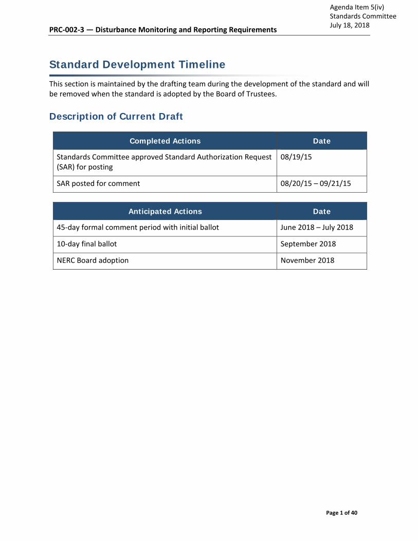
PRC-002-3 — Disturbance Monitoring and Reporting Requirements
Page 1 of 40
Standard Development Timeline
This section is maintained by the drafting team during the development of the standard and will be removed when the standard is adopted by the Board of Trustees.
Description of Current Draft
Completed Actions Date
Standards Committee approved Standard Authorization Request (SAR) for posting
08/19/15
SAR posted for comment 08/20/15 – 09/21/15
Anticipated Actions Date
45-day formal comment period with initial ballot June 2018 – July 2018
10-day final ballot September 2018
NERC Board adoption November 2018
Agenda Item 5(iv)Standards CommitteeJuly 18, 2018

PRC-002-3 — Disturbance Monitoring and Reporting Requirements
Page 2 of 40
A. Introduction
1. Title: Disturbance Monitoring and Reporting Requirements
2. Number: PRC-002-3
3. Purpose: To have adequate data available to facilitate analysis of Bulk Electric System (BES) Disturbances.
4. Applicability:
Functional Entities:
4.1 Reliability Coordinator
4.2 Transmission Owner
4.3 Generator Owner
5. Effective Dates:
See Implementation Plan B. Requirements and Measures
R1. Each Transmission Owner shall: [Violation Risk Factor: Lower ] [Time Horizon: Long-term Planning]
1.1. Identify BES buses for which sequence of events recording (SER) and fault recording (FR) data is required by using the methodology in PRC-002-2, Attachment 1.
1.2. Notify other owners of BES Elements connected to those BES buses, if any, within 90-calendar days of completion of Part 1.1, that those BES Elements require SER data and/or FR data.
1.3. Re-evaluate all BES buses at least once every five calendar years in accordance with Part 1.1 and notify other owners, if any, in accordance with Part 1.2, and implement the re-evaluated list of BES buses as per the Implementation Plan.
M1. The Transmission Owner has a dated (electronic or hard copy) list of BES buses for which SER and FR data is required, identified in accordance with PRC-002-2, Attachment 1, and evidence that all BES buses have been re-evaluated within the required intervals under Requirement R1. The Transmission Owner will also have dated (electronic or hard copy) evidence that it notified other owners in accordance with Requirement R1.
R2. Each Transmission Owner and Generator Owner shall have SER data for circuit breaker position (open/close) for each circuit breaker it owns connected directly to the BES buses identified in Requirement R1 and associated with the BES Elements at those BES buses. [Violation Risk Factor: Lower ] [Time Horizon: Long-term Planning]

PRC-002-3 — Disturbance Monitoring and Reporting Requirements
Page 3 of 40
M2. The Transmission Owner or Generator Owner has evidence (electronic or hard copy) of SER data for circuit breaker position as specified in Requirement R2. Evidence may include, but is not limited to: (1) documents describing the device interconnections and configurations which may include a single design standard as representative for common installations; or (2) actual data recordings; or (3) station drawings.
R3. Each Transmission Owner and Generator Owner shall have FR data to determine the following electrical quantities for each triggered FR for the BES Elements it owns connected to the BES buses identified in Requirement R1: [Violation Risk Factor: Lower] [Time Horizon: Long-term Planning]
3.1 Phase-to-neutral voltage for each phase of each specified BES bus.
3.2 Each phase current and the residual or neutral current for the following BES Elements:
3.2.1 Transformers that have a low-side operating voltage of 100kV or above.
3.2.2 Transmission Lines.
M3. The Transmission Owner or Generator Owner has evidence (electronic or hard copy) of FR data that is sufficient to determine electrical quantities as specified in Requirement R3. Evidence may include, but is not limited to: (1) documents describing the device specifications and configurations which may include a single design standard as representative for common installations; or (2) actual data recordings or derivations; or (3) station drawings.
R4. Each Transmission Owner and Generator Owner shall have FR data as specified in Requirement R3 that meets the following: [Violation Risk Factor: Lower] [Time Horizon: Long-term Planning]
4.1 A single record or multiple records that include:
• A pre-trigger record length of at least two cycles and a total record length of at least 30-cycles for the same trigger point, or
• At least two cycles of the pre-trigger data, the first three cycles of the post-trigger data, and the final cycle of the fault as seen by the fault recorder.
4.2 A minimum recording rate of 16 samples per cycle.
4.3 Trigger settings for at least the following:
4.3.1 Neutral (residual) overcurrent.
4.3.2 Phase undervoltage or overcurrent.
M4. The Transmission Owner or Generator Owner has evidence (electronic or hard copy) that FR data meets Requirement R4. Evidence may include, but is not limited to: (1) documents describing the device specification (R4, Part 4.2) and device configuration or settings (R4, Parts 4.1 and 4.3), or (2) actual data recordings or derivations.

PRC-002-3 — Disturbance Monitoring and Reporting Requirements
Page 4 of 40
R5. Each Reliability Coordinator shall: [Violation Risk Factor: Lower] [Time Horizon: Long-term Planning]
5.1 Identify BES Elements for which dynamic Disturbance recording (DDR) data is required, including the following:
5.1.1 Generating resource(s) with:
5.1.1.1 Gross individual nameplate rating greater than or equal to 500 MVA.
5.1.1.2 Gross individual nameplate rating greater than or equal to 300 MVA where the gross plant/facility aggregate nameplate rating is greater than or equal to 1,000 MVA.
5.1.2 Any one BES Element that is part of a stability (angular or voltage) related System Operating Limit (SOL).
5.1.3 Each terminal of a high voltage direct current (HVDC) circuit with a nameplate rating greater than or equal to 300 MVA, on the alternating current (AC) portion of the converter.
5.1.4 One or more BES Elements that are part of an Interconnection Reliability Operating Limit (IROL).
5.1.5 Any one BES Element within a major voltage sensitive area as defined by an area with an in-service undervoltage load shedding (UVLS) program.
5.2 Identify a minimum DDR coverage, inclusive of those BES Elements identified in Part 5.1, of at least:
5.2.1 One BES Element; and
5.2.2 One BES Element per 3,000 MW of the Reliability Coordinator’s historical simultaneous peak System Demand.
5.3 Notify all owners of identified BES Elements, within 90-calendar days of completion of Part 5.1, that their respective BES Elements require DDR data when requested.
5.4 Re-evaluate all BES Elements at least once every five calendar years in accordance with Parts 5.1 and 5.2, and notify owners in accordance with Part 5.3 to implement the re-evaluated list of BES Elements as per the Implementation Plan.
M5. The Reliability Coordinator has a dated (electronic or hard copy) list of BES Elements for which DDR data is required, developed in accordance with Requirement R5, Part 5.1 and Part 5.2; and re-evaluated in accordance with Part 5.4. The Reliability Coordinator has dated evidence (electronic or hard copy) that each Transmission Owner or Generator Owner has been notified in accordance with Requirement 5, Part 5.3. Evidence may include, but is not limited to: letters, emails, electronic files, or hard copy records demonstrating transmittal of information.

PRC-002-3 — Disturbance Monitoring and Reporting Requirements
Page 5 of 40
R6. Each Transmission Owner shall have DDR data to determine the following electrical quantities for each BES Element it owns for which it received notification as identified in Requirement R5: [Violation Risk Factor: Lower] [Time Horizon: Long-term Planning ]
6.1 One phase-to-neutral or positive sequence voltage.
6.2 The phase current for the same phase at the same voltage corresponding to the voltage in Requirement R6, Part 6.1, or the positive sequence current.
6.3 Real Power and Reactive Power flows expressed on a three phase basis corresponding to all circuits where current measurements are required.
6.4 Frequency of any one of the voltage(s) in Requirement R6, Part 6.1.
M6. The Transmission Owner has evidence (electronic or hard copy) of DDR data to determine electrical quantities as specified in Requirement R6. Evidence may include, but is not limited to: (1) documents describing the device specifications and configurations, which may include a single design standard as representative for common installations; or (2) actual data recordings or derivations; or (3) station drawings.
R7. Each Generator Owner shall have DDR data to determine the following electrical quantities for each BES Element it owns for which it received notification as identified in Requirement R5: [Violation Risk Factor: Lower] [Time Horizon: Long-term Planning]
7.1 One phase-to-neutral, phase-to-phase, or positive sequence voltage at either the generator step-up transformer (GSU) high-side or low-side voltage level.
7.2 The phase current for the same phase at the same voltage corresponding to the voltage in Requirement R7, Part 7.1, phase current(s) for any phase-to-phase voltages, or positive sequence current.
7.3 Real Power and Reactive Power flows expressed on a three phase basis corresponding to all circuits where current measurements are required.
7.4 Frequency of at least one of the voltages in Requirement R7, Part 7.1.
M7. The Generator Owner has evidence (electronic or hard copy) of DDR data to determine electrical quantities as specified in Requirement R7. Evidence may include, but is not limited to: (1) documents describing the device specifications and configurations, which may include a single design standard as representative for common installations; or (2) actual data recordings or derivations; or (3) station drawings.
R8. Each Transmission Owner and Generator Owner responsible for DDR data for the BES Elements identified in Requirement R5 shall have continuous data recording and storage. If the equipment was installed prior to the effective date of this standard and is not capable of continuous recording, triggered records must meet the following: [Violation Risk Factor: Lower] [Time Horizon: Long-term Planning]
8.1 Triggered record lengths of at least three minutes.

PRC-002-3 — Disturbance Monitoring and Reporting Requirements
Page 6 of 40
8.2 At least one of the following three triggers:
• Off nominal frequency trigger set at: Low High
o Eastern Interconnection <59.75 Hz >61.0 Hz o Western Interconnection <59.55 Hz >61.0 Hz o ERCOT Interconnection <59.35 Hz >61.0 Hz o Hydro-Quebec
Interconnection
<58.55 Hz
>61.5 Hz
• Rate of change of frequency trigger set at:
o Eastern Interconnection < -0.03125 Hz/sec > 0.125 Hz/sec o Western Interconnection < -0.05625 Hz/sec > 0.125 Hz/sec o ERCOT Interconnection < -0.08125 Hz/sec > 0.125 Hz/sec o Hydro-Quebec
Interconnection < -0.18125 Hz/sec
> 0.1875 Hz/sec
• Undervoltage trigger set no lower than 85 percent of normal operating voltage for a duration of 5 seconds.
M8. Each Transmission Owner and Generator Owner has dated evidence (electronic or
hard copy) of data recordings and storage in accordance with Requirement R8. Evidence may include, but is not limited to: (1) documents describing the device specifications and configurations, which may include a single design standard as representative for common installations; or (2) actual data recordings.
R9. Each Transmission Owner and Generator Owner responsible for DDR data for the BES Elements identified in Requirement R5 shall have DDR data that meet the following: [Violation Risk Factor: Lower] [Time Horizon: Long-term Planning]
9.1 Input sampling rate of at least 960 samples per second.
9.2 Output recording rate of electrical quantities of at least 30 times per second.
M9. The Transmission Owner or Generator Owner has evidence (electronic or hard copy) that DDR data meets Requirement R9. Evidence may include, but is not limited to: (1) documents describing the device specification, device configuration, or settings (R9, Part 9.1; R9, Part 9.2); or (2) actual data recordings (R9, Part 9.2).
R10. Each Transmission Owner and Generator Owner shall time synchronize all SER and FR data for the BES buses identified in Requirement R1 and DDR data for the BES

PRC-002-3 — Disturbance Monitoring and Reporting Requirements
Page 7 of 40
Elements identified in Requirement R5 to meet the following: [Violation Risk Factor: Lower] [Time Horizon: Long-term Planning]
10.1 Synchronization to Coordinated Universal Time (UTC) with or without a local time offset.
10.2 Synchronized device clock accuracy within ± 2 milliseconds of UTC.
M10. The Transmission Owner or Generator Owner has evidence (electronic or hard copy) of time synchronization described in Requirement R10. Evidence may include, but is not limited to: (1) documents describing the device specification, configuration, or setting; (2) time synchronization indication or status; or 3) station drawings.
R11. Each Transmission Owner and Generator Owner shall provide, upon request, all SER and FR data for the BES buses identified in Requirement R1 and DDR data for the BES Elements identified in Requirement R5 to the Reliability Coordinator, Regional Entity, or NERC in accordance with the following: [Violation Risk Factor: Lower] [Time Horizon: Long-term Planning]
11.1 Data will be retrievable for the period of 10-calendar days, inclusive of the day the data was recorded.
11.2 Data subject to Part 11.1 will be provided within 30-calendar days of a request unless an extension is granted by the requestor.
11.3 SER data will be provided in ASCII Comma Separated Value (CSV) format following Attachment 2.
11.4 FR and DDR data will be provided in electronic files that are formatted in conformance with C37.111, (IEEE Standard for Common Format for Transient Data Exchange (COMTRADE), revision C37.111-1999 or later.
11.5 Data files will be named in conformance with C37.232, IEEE Standard for Common Format for Naming Time Sequence Data Files (COMNAME), revision C37.232-2011 or later.
M11. The Transmission Owner or Generator Owner has evidence (electronic or hard copy) that data was submitted upon request in accordance with Requirement R11. Evidence may include, but is not limited to: (1) dated transmittals to the requesting entity with formatted records; (2) documents describing data storage capability, device specification, configuration or settings; or (3) actual data recordings.
R12. Each Transmission Owner and Generator Owner shall, within 90-calendar days of the discovery of a failure of the recording capability for the SER, FR or DDR data, either: [Violation Risk Factor: Lower] [Time Horizon: Long-term Planning]
• Restore the recording capability, or • Submit a Corrective Action Plan (CAP) to the Regional Entity and implement it.

PRC-002-3 — Disturbance Monitoring and Reporting Requirements
Page 8 of 40
M12. The Transmission Owner or Generator Owner has dated evidence (electronic or hard copy) that meets Requirement R12. Evidence may include, but is not limited to: (1) dated reports of discovery of a failure, (2) documentation noting the date the data recording was restored, (3) SCADA records, or (4) dated CAP transmittals to the Regional Entity and evidence that it implemented the CAP.
C. Compliance
1. Compliance Monitoring Process
1.1. Compliance Enforcement Authority
As defined in the NERC Rules of Procedure, “Compliance Enforcement Authority” (CEA) means NERC or the Regional Entity in their respective roles of monitoring and enforcing compliance with the NERC Reliability Standards.
1.2. Evidence Retention
The following evidence retention periods identify the period of time an entity is required to retain specific evidence to demonstrate compliance. For instances where the evidence retention period specified below is shorter than the time since the last audit, the Compliance Enforcement Authority may ask an entity to provide other evidence to show that it was compliant for the full time period since the last audit.
The Transmission Owner, Generator Owner, and Reliability Coordinator shall keep data or evidence to show compliance as identified below unless directed by its Compliance Enforcement Authority to retain specific evidence for a longer period of time as part of an investigation:
The Transmission Owner shall retain evidence of Requirement R1, Measure M1 for five calendar years.
The Transmission Owner shall retain evidence of Requirement R6, Measure M6 for three calendar years.
The Generator Owner shall retain evidence of Requirement R7, Measure M7 for three calendar years.
The Transmission Owner and Generator Owner shall retain evidence of requested data provided as per Requirements R2, R3, R4, R8, R9, R10, R11, and R12, Measures M2, M3, M4, M8, M9, M10, M11, and M12 for three calendar years.
The Reliability Coordinator shall retain evidence of Requirement R5, Measure M5 for five calendar years.
If a Transmission Owner, Generator Owner, or Reliability Coordinator is found non-compliant, it shall keep information related to the non-compliance until mitigation is completed and approved or for the time specified above, whichever is longer.

PRC-002-3 — Disturbance Monitoring and Reporting Requirements
Page 9 of 40
The Compliance Enforcement Authority shall keep the last audit records and all requested and submitted subsequent audit records.
1.3. Compliance Monitoring and Assessment Processes:
Compliance Audit
Self-Certification
Spot Checking
Compliance Violation Investigation
Self-Reporting
Complaints
1.4. Additional Compliance Information
None

PRC-002-3 — Disturbance Monitoring and Reporting Requirements
Page 10 of 40
Table of Compliance Elements
R # Time Horizon
VRF Violation Severity Levels
Lower VSL Moderate VSL High VSL Severe VSL
R1 Long-term Planning
Lower The Transmission Owner identified the BES buses as directed by Requirement R1, Part 1.1 or Part 1.3 for more than 80 percent but less than 100 percent of the required BES buses that they own.
OR
The Transmission Owner evaluated the BES buses as directed by Requirement R1, Part 1.1 or Part 1.3 but was late by 30-calendar days or less.
OR
The Transmission Owner as directed by Requirement R1, Part 1.2 was late in notifying the other
The Transmission Owner identified the BES buses as directed by Requirement R1, Part 1.1 or Part 1.3 for more than 70 percent but less than or equal to 80 percent of the required BES buses that they own.
OR
The Transmission Owner evaluated the BES buses as directed by Requirement R1, Part 1.1 or Part 1.3 but was late by greater than 30-calendar days and less than or equal to 60-calendar days.
OR
The Transmission Owner as directed by Requirement R1, Part
The Transmission Owner identified the BES buses as directed by Requirement R1, Part 1.1 or Part 1.3 for more than 60 percent but less than or equal to 70 percent of the required BES buses that they own.
OR
The Transmission Owner evaluated the BES buses as directed by Requirement R1, Part 1.1 or Part 1.3 but was late by greater than 60-calendar days and less than or equal to 90-calendar days.
OR
The Transmission Owner as directed by Requirement R1, Part
The Transmission Owner identified the BES buses as directed by Requirement R1, Part 1.1 or Part 1.3 for less than or equal to 60 percent of the required BES buses that they own.
OR
The Transmission Owner evaluated the BES buses as directed by Requirement R1, Part 1.1 or Part 1.3 but was late by greater than 90-calendar days.
OR
The Transmission Owner as directed by Requirement R1, Part 1.2 was late in notifying one or more other owners by

PRC-002-3 — Disturbance Monitoring and Reporting Requirements
Page 11 of 40
owners by 10-calendar days or less.
1.2 was late in notifying the other owners by greater than 10-calendar days but less than or equal to 20-calendar days.
1.2 was late in notifying the other owners by greater than 20-calendar days but less than or equal to 30-calendar days.
greater than 30-calendar days.
R2 Long-term Planning
Lower Each Transmission Owner or Generator Owner as directed by Requirement R2 had more than 80 percent but less than 100 percent of the total SER data for circuit breaker position (open/close) for each of the circuit breakers at the BES buses identified in Requirement R1.
Each Transmission Owner or Generator Owner as directed by Requirement R2 had more than 70 percent but less than or equal to 80 percent of the total SER data for circuit breaker position (open/close) for each of the circuit breakers at the BES buses identified in Requirement R1.
Each Transmission Owner or Generator Owner as directed by Requirement R2 had more than 60 percent but less than or equal to 70 percent of the total SER data for circuit breaker position (open/close) for each of the circuit breakers at the BES buses identified in Requirement R1.
Each Transmission Owner or Generator Owner as directed by Requirement R2 for less than or equal to 60 percent of the total SER data for circuit breaker position (open/close) for each of the circuit breakers at the BES buses identified in Requirement R1.
R3 Long-term Planning
Lower The Transmission Owner or Generator Owner had FR data as directed by Requirement R3, Parts 3.1 and 3.2 that covers more than 80 percent but less than 100 percent of the total set of required electrical
The Transmission Owner or Generator Owner had FR data as directed by Requirement R3, Parts 3.1 and 3.2 that covers more than 70 percent but less than or equal to 80 percent of the total set of required
The Transmission Owner or Generator Owner had FR data as directed by Requirement R3, Parts 3.1 and 3.2 that covers more than 60 percent but less than or equal to 70 percent of the total set of required
The Transmission Owner or Generator Owner had FR data as directed by Requirement R3, Parts 3.1 and 3.2 that covers less than or equal to 60 percent of the total set of required electrical quantities,

PRC-002-3 — Disturbance Monitoring and Reporting Requirements
Page 12 of 40
quantities, which is the product of the total number of monitored BES Elements and the number of specified electrical quantities for each BES Element.
electrical quantities, which is the product of the total number of monitored BES Elements and the number of specified electrical quantities for each BES Element.
electrical quantities, which is the product of the total number of monitored BES Elements and the number of specified electrical quantities for each BES Element.
which is the product of the total number of monitored BES Elements and the number of specified electrical quantities for each BES Element.
R4 Long-term Planning
Lower The Transmission Owner or Generator Owner had FR data that meets more than 80 percent but less than 100 percent of the total recording properties as specified in Requirement R4.
The Transmission Owner or Generator Owner had FR data that meets more than 70 percent but less than or equal to 80 percent of the total recording properties as specified in Requirement R4.
The Transmission Owner or Generator Owner had FR data that meets more than 60 percent but less than or equal to 70 percent of the total recording properties as specified in Requirement R4.
The Transmission Owner or Generator Owner had FR data that meets less than or equal to 60 percent of the total recording properties as specified in Requirement R4.
R5 Long-term Planning
Lower The Reliability Coordinator identified the BES Elements for which DDR data is required as directed by Requirement R5 for more than 80 percent but less than 100 percent of the required BES Elements included in Part 5.1.
The Reliability Coordinator identified the BES Elements for which DDR data is required as directed by Requirement R5 for more than 70 percent but less than or equal to 80 percent of the required BES Elements included in Part 5.1.
The Reliability Coordinator identified the BES Elements for which DDR data is required as directed by Requirement R5 for more than 60 percent but less than or equal to 70 percent of the required BES Elements included in Part 5.1.
The Reliability Coordinator identified the BES Elements for which DDR data is required as directed by Requirement R5 for less than or equal to 60 percent of the required BES Elements included in Part 5.1.
OR

PRC-002-3 — Disturbance Monitoring and Reporting Requirements
Page 13 of 40
OR
The Reliability Coordinator identified the BES Elements for DDR as directed by Requirement R5, Part 5.1 or Part 5.4 but was late by 30-calendar days or less.
OR
The Reliability Coordinator as directed by Requirement R5, Part 5.3 was late in notifying the owners by 10-calendar days or less.
OR
The Reliability Coordinator identified the BES Elements for DDR as directed by Requirement R5, Part 5.1 or Part 5.4 but was late by greater than 30-calendar days and less than or equal to 60 -calendar days.
OR
The Reliability Coordinator as directed by Requirement R5, Part 5.3 was late in notifying the owners by greater than 10-calendar days but less than or equal to 20-calendar days.
OR
The Reliability Coordinator identified the BES Elements for DDR as directed by Requirement R5, Part 5.1 or Part 5.4 but was late by greater than 60-calendar days and less than or equal to 90-calendar days.
OR
The Reliability Coordinator as directed by Requirement R5, Part 5.3 was late in notifying the owners by greater than 20-calendar days but less than or equal to 30-calendar days.
The Reliability Coordinator identified the BES Elements for DDR as directed by Requirement R5, Part 5.1 or Part 5.4 but was late by greater than 90-calendar days.
OR
The Reliability Coordinator as directed by Requirement R5, Part 5.3 was late in notifying one or more owners by greater than 30-calendar days.
OR
The Reliability Coordinator failed to ensure a minimum DDR coverage per Part 5.2.
R6 Long-term Planning
Lower The Transmission Owner had DDR data as directed by Requirement R6, Parts 6.1 through 6.4 that covered more than 80
The Transmission Owner had DDR data as directed by Requirement R6, Parts 6.1 through 6.4 for more than 70 percent
The Transmission Owner had DDR data as directed by Requirement R6, Parts 6.1 through 6.4 for more than 60 percent
The Transmission Owner failed to have DDR data as directed by Requirement R6, Parts 6.1 through 6.4.

PRC-002-3 — Disturbance Monitoring and Reporting Requirements
Page 14 of 40
percent but less than 100 percent of the total required electrical quantities for all applicable BES Elements.
but less than or equal to 80 percent of the total required electrical quantities for all applicable BES Elements.
but less than or equal to 70 percent of the total required electrical quantities for all applicable BES Elements.
R7 Long-term Planning
Lower The Generator Owner had DDR data as directed by Requirement R7, Parts 7.1 through 7.4 that covers more than 80 percent but less than 100 percent of the total required electrical quantities for all applicable BES Elements.
The Generator Owner had DDR data as directed by Requirement R7, Parts 7.1 through 7.4 for more than 70 percent but less than or equal to 80 percent of the total required electrical quantities for all applicable BES Elements.
The Generator Owner had DDR data as directed by Requirement R7, Parts 7.1 through 7.4 for more than 60 percent but less than or equal to 70 percent of the total required electrical quantities for all applicable BES Elements.
The Generator Owner failed to have DDR data as directed by Requirement R7, Parts 7.1 through 7.4.
R8 Long-term Planning
Lower The Transmission Owner or Generator Owner had continuous or non-continuous DDR data, as directed in Requirement R8, for more than 80 percent but less than 100 percent of the BES Elements they own as
The Transmission Owner or Generator Owner had continuous or non-continuous DDR data, as directed in Requirement R8, for more than 70 percent but less than or equal to 80 percent of the BES Elements they
The Transmission Owner or Generator Owner had continuous or non-continuous DDR data, as directed in Requirement R8, for more than 60 percent but less than or equal to 70 percent of the BES Elements they
The Transmission Owner or Generator Owner failed to have continuous or non-continuous DDR data, as directed in Requirement R8, for the BES Elements they own as determined in Requirement R5.

PRC-002-3 — Disturbance Monitoring and Reporting Requirements
Page 15 of 40
determined in Requirement R5.
own as determined in Requirement R5.
own as determined in Requirement R5.
R9 Long-term Planning
Lower The Transmission Owner or Generator Owner had DDR data that meets more than 80 percent but less than 100 percent of the total recording properties as specified in Requirement R9.
The Transmission Owner or Generator Owner had DDR data that meets more than 70 percent but less than or equal to 80 percent of the total recording properties as specified in Requirement R9.
The Transmission Owner or Generator Owner had DDR data that meets more than 60 percent but less than or equal to 70 percent of the total recording properties as specified in Requirement R9.
The Transmission Owner or Generator Owner had DDR data that meets less than or equal to 60 percent of the total recording properties as specified in Requirement R9.
R10 Long-term Planning
Lower The Transmission Owner or Generator Owner had time synchronization per Requirement R10, Parts 10.1 and 10.2 for SER, FR, and DDR data for more than 90 percent but less than 100 percent of the BES buses identified in Requirement R1 and BES Elements identified in Requirement R5 as directed by Requirement R10.
The Transmission Owner or Generator Owner had time synchronization per Requirement R10, Parts 10.1 and 10.2 for SER, FR, and DDR data for more than 80 percent but less than or equal to 90 percent of the BES buses identified in Requirement R1 and BES Elements identified in Requirement R5 as
The Transmission Owner or Generator Owner had time synchronization per Requirement R10, Parts 10.1 and 10.2 for SER, FR, and DDR data for more than 70 percent but less than or equal to 80 percent of the BES buses identified in Requirement R1 and BES Elements identified in Requirement R5 as
The Transmission Owner or Generator Owner failed to have time synchronization per Requirement R10, Parts 10.1 and 10.2 for SER, FR, and DDR data for less than or equal to 70 percent of the BES buses identified in Requirement R1 and BES Elements identified in Requirement R5 as directed by Requirement R10.

PRC-002-3 — Disturbance Monitoring and Reporting Requirements
Page 16 of 40
directed by Requirement R10.
directed by Requirement R10.
R11 Long-term Planning
Lower The Transmission Owner or Generator Owner as directed by Requirement R11, Part 11.1 provided the requested data more than 30-calendar days but less than 40-calendar days after the request unless an extension was granted by the requesting authority.
OR
The Transmission Owner or Generator
The Transmission Owner or Generator Owner as directed by Requirement R11, Part 11.1 provided the requested data more than 40-calendar days but less than or equal to 50-calendar days after the request unless an extension was granted by the requesting authority.
OR
The Transmission Owner or Generator
The Transmission Owner or Generator Owner as directed by Requirement R11, Part 11.1 provided the requested data more than 50-calendar days but less than or equal to 60-calendar days after the request unless an extension was granted by the requesting authority.
OR
The Transmission Owner or Generator
The Transmission Owner or Generator Owner as directed by Requirement R11, Part 11.1 failed to provide the requested data more than 60-calendar days after the request unless an extension was granted by the requesting authority.
OR
The Transmission Owner or Generator Owner as directed by Requirement R11

PRC-002-3 — Disturbance Monitoring and Reporting Requirements
Page 17 of 40
Owner as directed by Requirement R11 provided more than 90 percent but less than 100 percent of the requested data.
OR
The Transmission Owner or Generator Owner as directed by Requirement R11, Parts 11.3 through 11.5 provided more than 90 percent of the data but less than 100 percent of the data in the proper data format.
Owner as directed by Requirement R11 provided more than 80 percent but less than or equal to 90 percent of the requested data.
OR
The Transmission Owner or Generator Owner as directed by Requirement R11, Parts 11.3 through 11.5 provided more than 80 percent of the data but less than or equal to 90 percent of the data in the proper data format.
Owner as directed by Requirement R11 provided more than 70 percent but less than or equal to 80 percent of the requested data.
OR
The Transmission Owner or Generator Owner as directed by Requirement R11, Parts 11.3 through 11.5 provided more than 70 percent of the data but less than or equal to 80 percent of the data in the proper data format.
failed to provide less than or equal to 70 percent of the requested data.
OR
The Transmission Owner or Generator Owner as directed by Requirement R11, Parts 11.3 through 11.5 provided less than or equal to 70 percent of the data in the proper data format.
R12 Long-term Planning
Lower The Transmission Owner or Generator Owner as directed by Requirement R12 reported a failure and provided a Corrective Action Plan to the Regional Entity more than 90-calendar days but less than or equal
The Transmission Owner or Generator Owner as directed by Requirement R12 reported a failure and provided a Corrective Action Plan to the Regional Entity more than 100-calendar days but less than or
The Transmission Owner or Generator Owner as directed by Requirement R12 reported a failure and provided a Corrective Action Plan to the Regional Entity more than 110-calendar days but less than or
The Transmission Owner or Generator Owner as directed by Requirement R12 failed to report a failure and provide a Corrective Action Plan to the Regional Entity more than 120-calendar days after

PRC-002-3 — Disturbance Monitoring and Reporting Requirements
Page 18 of 40
to 100-calendar days after discovery of the failure.
equal to 110-calendar days after discovery of the failure.
equal to 120-calendar days after discovery of the failure.
OR
The Transmission Owner or Generator Owner as directed by Requirement R12 submitted a CAP to the Regional Entity but failed to implement it.
discovery of the failure.
OR
Transmission Owner or Generator Owner as directed by Requirement R12 failed to restore the recording capability and failed to submit a CAP to the Regional Entity.

PRC-002-3 — Disturbance Monitoring and Reporting Requirements
Page 19 of 40
D. Regional Variances None.
E. Interpretations
None.
F. Associated Documents
None.
G. References
IEEE C37.111: Common format for transient data exchange (COMTRADE) for power Systems.
IEEE C37.232-2011, IEEE Standard for Common Format for Naming Time Sequence Data Files (COMNAME). Standard published 11/09/2011 by IEEE.
NPCC SP6 Report Synchronized Event Data Reporting, revised March 31, 2005
U.S.-Canada Power System Outage Task Force, Final Report on the August 14, 2003 Blackout in the United States and Canada: Causes and Recommendations (2004).
U.S.-Canada Power System Outage Task Force Interim Report: Causes of the August 14th Blackout in the United States and Canada (Nov. 2003)
Version History
Version Date Action Change Tracking
0 February 8, 2005
Adopted by NERC Board of Trustees New
1 August 2, 2006 Adopted by NERC Board of Trustees Revised
2 November 13, 2014
Adopted by NERC Board of Trustees Revised under Project 2007-11 and merged with PRC-018-1.
2 September 24, 2015
FERC approved PRC-005-4. Docket No. RM15-4-000; Order No. 814

PRC-002-3 — Disturbance Monitoring and Reporting Requirements
Page 20 of 40
Attachment 1
Methodology for Selecting Buses for Capturing Sequence of Events Recording (SER) and Fault Recording (FR) Data
(Requirement R1)
To identify monitored BES buses for sequence of events recording (SER) and Fault recording (FR) data required by Requirement 1, each Transmission Owner shall follow sequentially, unless otherwise noted, the steps listed below:
Step 1. Determine a complete list of BES buses that it owns.
For the purposes of this standard, a single BES bus includes physical buses with breakers connected at the same voltage level within the same physical location sharing a common ground grid. These buses may be modeled or represented by a single node in fault studies. For example, ring bus or breaker-and-a-half bus configurations are considered to be a single bus.
Step 2. Reduce the list to those BES buses that have a maximum available calculated three phase short circuit MVA of 1,500 MVA or greater. If there are no buses on the resulting list, proceed to Step 7.
Step 3. Determine the 11 BES buses on the list with the highest maximum available calculated three phase short circuit MVA level. If the list has 11 or fewer buses, proceed to Step 7.
Step 4. Calculate the median MVA level of the 11 BES buses determined in Step 3.
Step 5. Multiply the median MVA level determined in Step 4 by 20 percent.
Step 6. Reduce the BES buses on the list to only those that have a maximum available calculated three phase short circuit MVA higher than the greater of:
● 1,500 MVA or
● 20 percent of median MVA level determined in Step 5.
Step 7. If there are no BES buses on the list: the procedure is complete and no FR and SER data will be required. Proceed to Step 9. If the list has 1 or more but less than or equal to 11 BES buses: FR and SER data is required at the BES bus with the highest maximum available calculated three phase short circuit MVA as determined in Step 3. Proceed to Step 9.

PRC-002-3 — Disturbance Monitoring and Reporting Requirements
Page 21 of 40
If the list has more than 11 BES buses: SER and FR data is required on at least the 10 percent of the BES buses determined in Step 6 with the highest maximum available calculated three phase short circuit MVA. Proceed to Step 8.
Step 8. SER and FR data is required at additional BES buses on the list determined in Step 6. The aggregate of the number of BES buses determined in Step 7 and this Step will be at least 20 percent of the BES buses determined in Step 6. The additional BES buses are selected, at the Transmission Owner’s discretion, to provide maximum wide-area coverage for SER and FR data. The following BES bus locations are recommended:
• Electrically distant buses or electrically distant from other DME devices. • Voltage sensitive areas. • Cohesive load and generation zones. • BES buses with a relatively high number of incident Transmission circuits. • BES buses with reactive power devices. • Major Facilities interconnecting outside the Transmission Owner’s area.
Step 9. The list of monitored BES buses for SER and FR data for Requirement R1 is the
aggregate of the BES buses determined in Steps 7 and 8.

PRC-002-3 — Disturbance Monitoring and Reporting Requirements
Page 22 of 40
Attachment 2
Sequence of Events Recording (SER) Data Format
(Requirement R11, Part 11.3)
Date, Time, Local Time Code, Substation, Device, State1
08/27/13, 23:58:57.110, -5, Sub 1, Breaker 1, Close
08/27/13, 23:58:57.082, -5, Sub 2, Breaker 2, Close
08/27/13, 23:58:47.217, -5, Sub 1, Breaker 1, Open
08/27/13, 23:58:47.214, -5, Sub 2, Breaker 2, Open
1 “OPEN” and “CLOSE” are used as examples. Other terminology such as TRIP, TRIP TO LOCKOUT, RECLOSE, etc. is also acceptable.

PRC-002-3 — Disturbance Monitoring and Reporting Requirements
Page 23 of 40
High Level Requirement Overview
Requireme
nt
Entity
Identify BES
Buses
Notification
SER
FR
5 Year
Re-evaluatio
n
R1 TO X X X X X
R2 TO | GO
X
R3 TO | GO
X
R4 TO | GO
X
Requireme
nt
Entity
Identify BES
Elements
Notification
DDR
5 Year Re-evaluation
R5 RC X X X X
R6 TO
X
R7 GO
X
R8 TO | GO
X
R9 TO | GO
X
Requireme
nt
Entity
Time Synchronizati
on
Provide SER, FR, DDR Data
SER, FR, DDR Availability
R10 TO | GO X
R11 TO | GO
X
R12 TO | GO
X

PRC-002-3 — Disturbance Monitoring and Reporting Requirements
Page 24 of 40
Rationale: During development of this standard, text boxes were embedded within the standard to explain the rationale for various parts of the standard. Upon BOT approval, the text from the rationale text boxes was moved to this section. Rationale for Functional Entities: Because the Reliability Coordinator has the best wide-area view of the BES, the Reliability Coordinator is most suited to be responsible for determining the BES Elements for which dynamic Disturbance recording (DDR) data is required. The Transmission Owners and Generator Owners will have the responsibility for ensuring that adequate data is available for those BES Elements selected. BES buses where sequence of events recording (SER) and fault recording (FR) data is required are best selected by Transmission Owners because they have the required tools, information, and working knowledge of their Systems to determine those buses. The Transmission Owners and Generator Owners that own BES Elements on those BES buses will have the responsibility for ensuring that adequate data is available. Rationale for R1: Analysis and reconstruction of BES events requires SER and FR data from key BES buses. Attachment 1 provides a uniform methodology to identify those BES buses. Repeated testing of the Attachment 1 methodology has demonstrated the proper distribution of SER and FR data collection. Review of actual BES short circuit data received from the industry in response to the DMSDT’s data request (June 5, 2013 through July 5, 2013) illuminated a strong correlation between the available short circuit MVA at a Transmission bus and its relative size and importance to the BES based on (i) its voltage level, (ii) the number of Transmission Lines and other BES Elements connected to the BES bus, and (iii) the number and size of generating units connected to the bus. BES buses with a large short circuit MVA level are BES Elements that have a significant effect on System reliability and performance. Conversely, BES buses with very low short circuit MVA levels seldom cause wide-area or cascading System events, so SER and FR data from those BES Elements are not as significant. After analyzing and reviewing the collected data submittals from across the continent, the threshold MVA values were chosen to provide sufficient data for event analysis using engineering and operational judgment. Concerns have existed that the defined methodology for bus selection will overly concentrate data to selected BES buses. For the purpose of PRC-002-2, there are a minimum number of BES buses for which SER and FR data is required based on the short circuit level. With these concepts and the objective being sufficient recording coverage for event analysis, the DMSDT developed the procedure in Attachment 1 that utilizes the maximum available calculated three phase short circuit MVA. This methodology ensures comparable and sufficient coverage for SER and FR data regardless of variations in the size and System topology of Transmission Owners across all Interconnections. Additionally, this methodology provides a degree of flexibility for the use of judgment in the selection process to ensure sufficient distribution.

PRC-002-3 — Disturbance Monitoring and Reporting Requirements
Page 25 of 40
BES buses where SER and FR data is required are best selected by Transmission Owners because they have the required tools, information, and working knowledge of their Systems to determine those buses.
Each Transmission Owner must re-evaluate the list of BES buses at least every five calendar years to address System changes since the previous evaluation. Changes to the BES do not mandate immediate inclusion of BES buses into the currently enforced list, but the list of BES buses will be re-evaluated at least every five calendar years to address System changes since the previous evaluation.
Since there may be multiple owners of equipment that comprise a BES bus, the notification required in R1 is necessary to ensure all owners are notified.
A 90-calendar day notification deadline provides adequate time for the Transmission Owner to make the appropriate determination and notification. Rationale for R2: The intent is to capture SER data for the status (open/close) of the circuit breakers that can interrupt the current flow through each BES Element connected to a BES bus. Change of state of circuit breaker position, time stamped according to Requirement R10 to a time synchronized clock, provides the basis for assembling the detailed sequence of events timeline of a power System Disturbance. Other status monitoring nomenclature can be used for devices other than circuit breakers. Rationale for R3: The required electrical quantities may either be directly measured or determinable if sufficient FR data is captured (e.g. residual or neutral current if the phase currents are directly measured). In order to cover all possible fault types, all BES bus phase-to-neutral voltages are required to be determinable for each BES bus identified in Requirement R1. BES bus voltage data is adequate for System Disturbance analysis. Phase current and residual current are required to distinguish between phase faults and ground faults. It also facilitates determination of the fault location and cause of relay operation. For transformers (Part 3.2.1), the data may be from either the high-side or the low-side of the transformer. Generator step-up transformers (GSUs) and leads that connect the GSU transformer(s) to the Transmission System that are used exclusively to export energy directly from a BES generating unit or generating plant are excluded from Requirement R3 because the fault current contribution from a generator to a fault on the Transmission System will be captured by FR data on the Transmission System, and Transmission System FR will capture faults on the generator interconnection. Generator Owners may install this capability or, where the Transmission Owners already have suitable FR data, contract with the Transmission Owner. However, when required, the Generator Owner is still responsible for the provision of this data.

PRC-002-3 — Disturbance Monitoring and Reporting Requirements
Page 26 of 40
Rationale for R4: Time stamped pre- and post-trigger fault data aid in the analysis of power System operations and determination if operations were as intended. System faults generally persist for a short time period, thus a 30-cycle total minimum record length is adequate. Multiple records allow for legacy microprocessor relays which, when time-synchronized, are capable of providing adequate fault data but not capable of providing fault data in a single record with 30-contiguous cycles total. A minimum recording rate of 16 samples per cycle (960 Hz) is required to get sufficient point on wave data for recreating accurate fault conditions. Rationale for R5: DDR is used for capturing the BES transient and post-transient response following Disturbances, and the data is used for event analysis and validating System performance. DDR plays a critical role in wide-area Disturbance analysis, and Requirement R5 ensures there is adequate wide-area coverage of DDR data for specific BES Elements to facilitate accurate and efficient event analysis. The Reliability Coordinator has the best wide-area view of the System and needs to ensure that there are sufficient BES Elements identified for DDR data capture. The identification of BES Elements requiring DDR data as per Requirement R5 is based upon industry experience with wide-area Disturbance analysis and the need for adequate data to facilitate event analysis. Ensuring data is captured for these BES Elements will significantly improve the accuracy of analysis and understanding of why an event occurred, not simply what occurred. From its experience with changes to the Bulk Electric System that would affect DDR, the DMSDT decided that the five calendar year re-evaluation of the list is a reasonable interval for this review. Changes to the BES do not mandate immediate inclusion of BES Elements into the in force list, but the list of BES Elements will be re-evaluated at least every five calendar years to address System changes since the previous evaluation. However, this standard does not preclude the Reliability Coordinator from performing this re-evaluation more frequently to capture updated BES Elements.
The Reliability Coordinator must notify all owners of the selected BES Elements that DDR data is required for this standard. The Reliability Coordinator is only required to share the list of selected BES Elements that each Transmission Owner and Generator Owner respectively owns, not the entire list. This communication of selected BES Elements is required to ensure that the owners of the respective BES Elements are aware of their responsibilities under this standard.
Implementation of the monitoring equipment is the responsibility of the respective Transmission Owners and Generator Owners, the timeline for installing this capability is outlined in the Implementation Plan, and starts from notification of the list from the Reliability Coordinator. Data for each BES Element as defined by the Reliability Coordinator must be provided; however, this data can be either directly measured or accurately calculated. With the exception of HVDC circuits, DDR data is only required for one end or terminal of the BES Elements selected. For example, DDR data must be provided for at least one terminal of a

PRC-002-3 — Disturbance Monitoring and Reporting Requirements
Page 27 of 40
Transmission Line or generator step-up (GSU) transformer, but not both terminals. For an interconnection between two Reliability Coordinators, each Reliability Coordinator will consider this interconnection independently, and are expected to work cooperatively to determine how to monitor the BES Elements that require DDR data. For an interconnection between two TO’s, or a TO and a GO, the Reliability Coordinator will determine which entity will provide the data. The Reliability Coordinator will notify the owners that their BES Elements require DDR data.
Refer to the Guidelines and Technical Basis Section for more detail on the rationale and technical reasoning for each identified BES Element in Requirement R5, Part 5.1; monitoring these BES Elements with DDR will facilitate thorough and informative event analysis of wide-area Disturbances on the BES. Part 5.2 is included to ensure wide-area coverage across all Reliability Coordinators. It is intended that each Reliability Coordinator will have DDR data for one BES Element and at least one additional BES Element per 3,000 MW of its historical simultaneous peak System Demand. Rationale for R6: DDR is used to measure transient response to System Disturbances during a relatively balanced post-fault condition. Therefore, it is sufficient to provide a phase-to-neutral voltage or positive sequence voltage. The electrical quantities can be determined (calculated, derived, etc.).
Because all of the BES buses within a location are at the same frequency, one frequency measurement is adequate.
The data requirements for PRC-002-2 are based on a System configuration assuming all normally closed circuit breakers on a BES bus are closed. Rationale for R7: A crucial part of wide-area Disturbance analysis is understanding the dynamic response of generating resources. Therefore, it is necessary for Generator Owners to have DDR at either the high- or low-side of the generator step-up transformer (GSU) measuring the specified electrical quantities to adequately capture generator response. This standard defines the ‘what’ of DDR, not the ‘how’. Generator Owners may install this capability or, where the Transmission Owners already have suitable DDR data, contract with the Transmission Owner. However, the Generator Owner is still responsible for the provision of this data. Rationale for R8: Large scale System outages generally are an evolving sequence of events that occur over an extended period of time, making DDR data essential for event analysis. Data available pre- and post-contingency helps identify the causes and effects of each event leading to outages. Therefore, continuous recording and storage are necessary to ensure sufficient data is available for the entire event. Existing DDR data recording across the BES may not record continuously. To accommodate its use for the purposes of this standard, triggered records are acceptable if the equipment was installed prior to the effective date of this standard. The frequency triggers are defined based on the dynamic response associated with each Interconnection. The undervoltage trigger is

PRC-002-3 — Disturbance Monitoring and Reporting Requirements
Page 28 of 40
defined to capture possible delayed undervoltage conditions such as Fault Induced Delayed Voltage Recovery (FIDVR). Rationale for R9: An input sampling rate of at least 960 samples per second, which corresponds to 16 samples per cycle on the input side of the DDR equipment, ensures adequate accuracy for calculation of recorded measurements such as complex voltage and frequency. An output recording rate of electrical quantities of at least 30 times per second refers to the recording and measurement calculation rate of the device. Recorded measurements of at least 30 times per second provide adequate recording speed to monitor the low frequency oscillations typically of interest during power System Disturbances. Rationale for R10: Time synchronization of Disturbance monitoring data is essential for time alignment of large volumes of geographically dispersed records from diverse recording sources. Coordinated Universal Time (UTC) is a recognized time standard that utilizes atomic clocks for generating precision time measurements. All data must be provided in UTC formatted time either with or without the local time offset, expressed as a negative number (the difference between UTC and the local time zone where the measurements are recorded). Accuracy of time synchronization applies only to the clock used for synchronizing the monitoring equipment. The equipment used to measure the electrical quantities must be time synchronized to ± 2 ms accuracy; however, accuracy of the application of this time stamp and therefore the accuracy of the data itself is not mandated. This is because of inherent delays associated with measuring the electrical quantities and events such as breaker closing, measurement transport delays, algorithm and measurement calculation techniques, etc. Ensuring that the monitoring devices internal clocks are within ± 2 ms accuracy will suffice with respect to providing time synchronized data. Rationale for R11: Wide-area Disturbance analysis includes data recording from many devices and entities. Standardized formatting and naming conventions of these files significantly improves timely analysis. Providing the data within 30-calendar days (or the granted extension time), subject to Part 11.1, allows for reasonable time to collect the data and perform any necessary computations or formatting.
Data is required to be retrievable for 10-calendar days inclusive of the day the data was recorded, i.e. a 10-calendar day rolling window of available data. Data hold requests are usually initiated the same or next day following a major event for which data is requested. A 10-calendar day time frame provides a practical limit on the duration of data required to be stored and informs the requesting entities as to how long the data will be available. The requestor of data has to be aware of the Part 11.1 10-calendar day retrievability because requiring data retention for a longer period of time is expensive and unnecessary.

PRC-002-3 — Disturbance Monitoring and Reporting Requirements
Page 29 of 40
SER data shall be provided in a simple ASCII .CSV format as outlined in Attachment 2. Either equipment can provide the data or a simple conversion program can be used to convert files into this format. This will significantly improve the data format for event records, enabling the use of software tools for analyzing the SER data.
Part 11.4 specifies FR and DDR data files be provided in conformance with IEEE C37.111, IEEE Standard for Common Format for Transient Exchange (COMTRADE), revision 1999 or later. The use of IEEE C37.111-1999 or later is well established in the industry. C37.111-2013 is a version of COMTRADE that includes an annex describing the application of the COMTRADE standard to synchrophasor data; however, version C37.111-1999 is commonly used in the industry today.
Part 11.5 uses a standardized naming format, C37.232-2011, IEEE Standard for Common Format for Naming Time Sequence Data Files (COMNAME), for providing Disturbance monitoring data. This file format allows a streamlined analysis of large Disturbances, and includes critical records such as local time offset associated with the synchronization of the data. Rationale for R12: Each Transmission Owner and Generator Owner who owns equipment used for collecting the data required for this standard must repair any failures within 90-calendar days to ensure that adequate data is available for event analysis. If the Disturbance monitoring capability cannot be restored within 90-calendar days (e.g. budget cycle, service crews, vendors, needed outages, etc.), the entity must develop a Corrective Action Plan (CAP) for restoring the data recording capability. The timeline required for the CAP depends on the entity and the type of data required. It is treated as a failure if the recording capability is out of service for maintenance and/or testing for greater than 90-calendar days. An outage of the monitored BES Element does not constitute a failure of the Disturbance monitoring capability.

PRC-002-3 — Disturbance Monitoring and Reporting Requirements
Page 30 of 40
Guidelines and Technical Basis Section
Introduction
The emphasis of PRC-002-2 is not on how Disturbance monitoring data is captured, but what Bulk Electric System data is captured. There are a variety of ways to capture the data PRC-002-2 addresses, and existing and currently available equipment can meet the requirements of this standard. PRC-002-2 also addresses the importance of addressing the availability of Disturbance monitoring capability to ensure the completeness of BES data capture.
The data requirements for PRC-002-2 are based on a System configuration assuming all normally closed circuit breakers on a bus are closed.
PRC-002-2 addresses “what” data is recorded, not “how” it is recorded.
Guideline for Requirement R1:
Sequence of events and fault recording for the analysis, reconstruction, and reporting of System Disturbances is important. However, SER and FR data is not required at every BES bus on the BES to conduct adequate or thorough analysis of a Disturbance. As major tools of event analysis, the time synchronized time stamp for a breaker change of state and the recorded waveforms of voltage and current for individual circuits allows the precise reconstruction of events of both localized and wide-area Disturbances. More quality information is always better than less when performing event analysis. However, 100 percent coverage of all BES Elements is not practical nor required for effective analysis of wide-area Disturbances. Therefore, selectivity of required BES buses to monitor is important for the following reasons:
1. Identify key BES buses with breakers where crucial information is available when required.
2. Avoid excessive overlap of coverage. 3. Avoid gaps in critical coverage. 4. Provide coverage of BES Elements that could propagate a Disturbance. 5. Avoid mandates to cover BES Elements that are more likely to be a casualty of a
Disturbance rather than a cause. 6. Establish selection criteria to provide effective coverage in different regions of the
continent.
The major characteristics available to determine the selection process are:
1. System voltage level; 2. The number of Transmission Lines into a substation or switchyard; 3. The number and size of connected generating units; 4. The available short circuit levels.

PRC-002-3 — Disturbance Monitoring and Reporting Requirements
Page 31 of 40
Although it is straightforward to establish criteria for the application of identified BES buses, analysis was required to establish a sound technical basis to fulfill the required objectives. To answer these questions and establish criteria for BES buses of SER and FR, the DMSDT established a sub-team referred to as the Monitored Value Analysis Team (MVA Team). The MVA Team collected information from a wide variety of Transmission Systems throughout the continent to analyze Transmission buses by the characteristics previously identified for the selection process.
The MVA Team learned that the development of criteria is not possible for adequate SER and FR coverage, based solely upon simple, bright line characteristics, such as the number of lines into a substation or switchyard at a particular voltage level or at a set level of short circuit current. To provide the appropriate coverage, a relatively simple but effective Methodology for Selecting Buses for Capturing Sequence of Events Recording (SER) and Fault Recording (FR) Data was developed. This Procedure, included as Attachment 1, assists entities in fulfilling Requirement R1 of the standard.
The Methodology for Selecting Buses for Capturing Sequence of Events Recording (SER) and Fault Recording (FR) Data is weighted to buses with higher short circuit levels. This is chosen for the following reasons:
1. The method is voltage level independent. 2. It is likely to select buses near large generation centers. 3. It is likely to select buses where delayed clearing can cause Cascading. 4. Selected buses directly correlate to the Universal Power Transfer equation: Lower
Impedance – increased power flows – greater System impact. To perform the calculations of Attachment 1, the following information below is required and the following steps (provided in summary form) are required for Systems with more than 11 BES buses with three phase short circuit levels above 1,500 MVA.
1. Total number of BES buses in the Transmission System under evaluation. a. Only tangible substation or switchyard buses are included. b. Pseudo buses created for analysis purposes in System models are excluded.
2. Determine the three phase short circuit MVA for each BES bus. 3. Exclude BES buses from the list with short circuit levels below 1,500 MVA. 4. Determine the median short circuit for the top 11 BES buses on the list (position number
6). 5. Multiply median short circuit level by 20 percent. 6. Reduce the list of BES buses to those with short circuit levels higher than 20 percent of
the median. 7. Apply SER and FR at BES buses with short circuit levels in the top 10 percent of the list
(from 6).

PRC-002-3 — Disturbance Monitoring and Reporting Requirements
Page 32 of 40
8. Apply SER and FR at BES buses at an additional 10 percent of the list using engineering judgment, and allowing flexibility to factor in the following considerations: • Electrically distant BES buses or electrically distant from other DME devices • Voltage sensitive areas • Cohesive load and generation zones • BES buses with a relatively high number of incident Transmission circuits • BES buses with reactive power devices • Major facilities interconnecting outside the Transmission Owner’s area.
For event analysis purposes, more valuable information is attained about generators and their response to System events pre- and post-contingency through DDR data versus SER or FR records. SER data of the opening of the primary generator output interrupting devices (e.g. synchronizing breaker) may not reliably indicate the actual time that a generator tripped; for instance, when it trips on reverse power after loss of its prime mover (e.g. combustion or steam turbine). As a result, this standard only requires DDR data. The re-evaluation interval of five years was chosen based on the experience of the DMSDT to address changing System configurations while creating balance in the frequency of re-evaluations.
Guideline for Requirement R2:
Analyses of wide-area Disturbances often begin by evaluation of SERs to help determine the initiating event(s) and follow the Disturbance propagation. Recording of breaker operations help determine the interruption of line flows while generator loading is best determined by DDR data, since generator loading can be essentially zero regardless of breaker position. However, generator breakers directly connected to an identified BES bus are required to have SER data captured. It is important in event analysis to know when a BES bus is cleared regardless of a generator’s loading.
Generator Owners are included in this requirement because a Generator Owner may, in some instances, own breakers directly connected to the Transmission Owner’s BES bus.
Guideline for Requirement R3:
The BES buses for which FR data is required are determined based on the methodology described in Attachment 1 of the standard. The BES Elements connected to those BES buses for which FR data is required include:
- Transformers with a low-side operating voltage of 100kV or above - Transmission Lines

PRC-002-3 — Disturbance Monitoring and Reporting Requirements
Page 33 of 40
Only those BES Elements that are identified as BES as defined in the latest in effect NERC definition are to be monitored. For example, radial lines or transformers with low-side voltage less than 100kV are not included. FR data must be determinable from each terminal of a BES Element connected to applicable BES buses. Generator step-up transformers (GSU) are excluded from the above based on the following:
- Current contribution from a generator in case of fault on the Transmission System will be captured by FR data on the Transmission System.
- For faults on the interconnection to generating facilities it is sufficient to have fault current data from the Transmission station end of the interconnection. Current contribution from a generator can be readily calculated if needed.
The DMSDT, after consulting with NERC’s Event Analysis group, determined that DDR data from selected generator locations was more important for event analysis than FR data. Recording of Electrical Quantities For effective fault analysis it is necessary to know values of all phase and neutral currents and all phase-to-neutral voltages. Based on such FR data it is possible to determine all fault types. FR data also augments SERs in evaluating circuit breaker operation. Current Recordings The required electrical quantities are normally directly measured. Certain quantities can be derived if sufficient data is measured, for example residual or neutral currents. Since a Transmission System is generally well balanced, with phase currents having essentially similar magnitudes and phase angle differences of 120○, during normal conditions there is negligible neutral (residual) current. In case of a ground fault the resulting phase current imbalance produces residual current that can be either measured or calculated.
Neutral current, also known as ground or residual current Ir, is calculated as a sum of vectors of three phase currents: Ir =3•I0 =IA +IB +IC
I0 - Zero-sequence current
IA, IB, IC - Phase current (vectors)
Another example of how required electrical quantities can be derived is based on Kirchhoff’s Law. Fault currents for one of the BES Elements connected to a particular BES bus can be derived as a vectorial sum of fault currents recorded at the other BES Elements connected to that BES bus. Voltage Recordings

PRC-002-3 — Disturbance Monitoring and Reporting Requirements
Page 34 of 40
Voltages are to be recorded or accurately determined at applicable BES buses.
Guideline for Requirement R4:
Pre- and post-trigger fault data along with the SER breaker data, all time stamped to a common clock at millisecond accuracy, aid in the analysis of protection System operations after a fault to determine if a protection System operated as designed. Generally speaking, BES faults persist for a very short time period, approximately 1 to 30 cycles, thus a 30-cycle record length provides adequate data. Multiple records allow for legacy microprocessor relays which, when time synchronized to a common clock, are capable of providing adequate fault data but not capable of providing fault data in a single record with 30-contiguous cycles total.
A minimum recording rate of 16 samples per cycle is required to get accurate waveforms and to get 1 millisecond resolution for any digital input which may be used for FR.
FR triggers can be set so that when the monitored value on the recording device goes above or below the trigger value, data is recorded. Requirement R4, sub-Part 4.3.1 specifies a neutral (residual) overcurrent trigger for ground faults. Requirement R4, sub-Part 4.3.2 specifies a phase undervoltage or overcurrent trigger for phase-to-phase faults.
Guideline for Requirement R5:
DDR data is used for wide-area Disturbance monitoring to determine the System’s electromechanical transient and post-transient response and validate System model performance. DDR is typically located based on strategic studies which include angular, frequency, voltage, and oscillation stability. However, for adequately monitoring the System’s dynamic response and ensuring sufficient coverage to determine System performance, DDR is required for key BES Elements in addition to a minimum requirement of DDR coverage.
Each Reliability Coordinator is required to identify sufficient DDR data capture for, at a minimum, one BES Element and then one additional BES Element per 3,000 MW of historical simultaneous peak System Demand. This DDR data is included to provide adequate System wide coverage across an Interconnection. To clarify, if any of the key BES Elements requiring DDR monitoring are within the Reliability Coordinator Area, DDR data capability is required. If a Reliability Coordinator does not meet the requirements of Part 5.1, additional coverage had to be specified.
Loss of large generating resources poses a frequency and angular stability risk for all Interconnections across North America. Data capturing the dynamic response of these machines during a Disturbance helps the analysis of large Disturbances. Having data regarding generator dynamic response to Disturbances greatly improves understanding of why an event occurs rather than what occurred. To determine and provide the basis for unit size criteria, the DMSDT acquired specific generating unit data from NERC’s Generating Availability Data System (GADS) program. The data contained generating unit size information for each generating unit in North America which was reported in 2013 to the NERC GADS program. The DMSDT analyzed the spreadsheet data to determine: (i) how many units were above or below selected size

PRC-002-3 — Disturbance Monitoring and Reporting Requirements
Page 35 of 40
thresholds; and (ii) the aggregate sum of the ratings of the units within the boundaries of those thresholds. Statistical information about this data was then produced, i.e. averages, means and percentages. The DMSDT determined the following basic information about the generating units of interest (current North America fleet, i.e. units reporting in 2013) included in the spreadsheet:
• The number of individual generating units in total included in the spreadsheet. • The number of individual generating units rated at 20 MW or larger included in the
spreadsheet. These units would generally require that their owners be registered as GOs in the NERC CMEP.
• The total number of units within selected size boundaries. • The aggregate sum of ratings, in MWs, of the units within the boundaries of those
thresholds.
The information in the spreadsheet does not provide information by which the plant information location of each unit can be determined, i.e. the DMSDT could not use the information to determine which units were located together at a given generation site or facility. From this information, the DMSDT was able to reasonably speculate the generating unit size thresholds proposed in Requirement R5, sub-Part 5.1.1 of the standard. Generating resources intended for DDR data recording are those individual units with gross nameplate ratings “greater than or equal to 500 MVA”. The 500 MVA individual unit size threshold was selected because this number roughly accounts for 47 percent of the generating capacity in NERC footprint while only requiring DDR coverage on about 12.5 percent of the generating units. As mentioned, there was no data pertaining to unit location for aggregating plant/facility sizes. However, Requirement R5, sub-Part 5.1.1 is included to capture larger units located at large generating plants which could pose a stability risk to the System if multiple large units were lost due to electrical or non-electrical contingencies. For generating plants, each individual generator at the plant/facility with a gross nameplate rating greater than or equal to 300 MVA must have DDR where the gross nameplate rating of the plant/facility is greater than or equal to 1,000 MVA. The 300 MVA threshold was chosen based on the DMSDT’s judgment and experience. The incremental impact to the number of units requiring monitoring is expected to be relatively low. For combined cycle plants where only one generator has a rating greater than or equal to 300MVA, that is the only generator that would need DDR.
Permanent System Operating Limits (SOLs) are used to operate the System within reliable and secure limits. In particular, SOLs related to angular or voltage stability have a significant impact on BES reliability and performance. Therefore, at least one BES Element of an SOL should be monitored.
The draft standard requires “One or more BES Elements that are part of an Interconnection Reliability Operating Limits (IROLs).” Interconnection Reliability Operating Limits (IROLs) are included because the risk of violating these limits poses a risk to System stability and the potential for cascading outages. IROLs may be defined by a single or multiple monitored BES

PRC-002-3 — Disturbance Monitoring and Reporting Requirements
Page 36 of 40
Element(s) and contingent BES Element(s). The standard does not dictate selection of the contingent and/or monitored BES Elements. Rather the Drafting Team believes this determination is best made by the Reliability Coordinator for each IROL considered based on the severity of violating this IROL.
Locations where an undervoltage load shedding (UVLS) program is deployed are prone to voltage instability since they are generally areas of significant Demand. The Reliability Coordinator will identify these areas where a UVLS is in service and identify a useful and effective BES Element to monitor for DDR such that action of the UVLS or voltage instability on the BES could be captured. For example, a major 500kV or 230kV substation on the EHV System close to the load pocket where the UVLS is deployed would likely be a valuable electrical location for DDR coverage and would aid in post-Disturbance analysis of the load area’s response to large System excursions (voltage, frequency, etc.).
Guideline for Requirement R6:
DDR data shows transient response to System Disturbances after a fault is cleared (post-fault), under a relatively balanced operating condition. Therefore, it is sufficient to provide a single phase-to-neutral voltage or positive sequence voltage. Recording of all three phases of a circuit is not required, although this may be used to compute and record the positive sequence voltage. The bus where a voltage measurement is required is based on the list of BES Elements defined by the Reliability Coordinator in Requirement R5. The intent of the standard is not to require a separate voltage measurement of each BES Element where a common bus voltage measurement is available. For example, a breaker-and-a-half or double-bus configuration with a North (or East) Bus and South (or West) Bus, would require both buses to have voltage recording because either can be taken out of service indefinitely with the targeted BES Element remaining in service. This may be accomplished either by recording both bus voltages separately, or by providing a selector switch to connect either of the bus voltage sources to a single recording input of the DDR device. This component of the requirement is therefore included to mitigate the potential of failed frequency, phase angle, real power, and reactive power calculations due to voltage measurements removed from service while sufficient voltage measurement is actually available during these operating conditions. It must be emphasized that the data requirements for PRC-002-2 are based on a System configuration assuming all normally closed circuit breakers on a bus are closed. When current recording is required, it should be on the same phase as the voltage recording taken at the location if a single phase-to-neutral voltage is provided. Positive sequence current recording is also acceptable.

PRC-002-3 — Disturbance Monitoring and Reporting Requirements
Page 37 of 40
For all circuits where current recording is required, Real and Reactive Power will be recorded on a three phase basis. These recordings may be derived either from phase quantities or from positive sequence quantities. Guideline for Requirement R7:
All Guidelines specified for Requirement R6 apply to Requirement R7. Since either the high- or low-side windings of the generator step-up transformer (GSU) may be connected in delta, phase-to-phase voltage recording is an acceptable voltage recording. As was explained in the Guideline for Requirement R6, the BES is operating under a relatively balanced operating condition and, if needed, phase-to-neutral quantities can be derived from phase-to-phase quantities.
Again it must be emphasized that the data requirements for PRC-002-2 are based on a System configuration assuming all normally closed circuit breakers on a bus are closed.
Guideline for Requirement R8:
Wide-area System outages are generally an evolving sequence of events that occur over an extended period of time, making DDR data essential for event analysis. Pre- and post-contingency data helps identify the causes and effects of each event leading to the outages. This drives a need for continuous recording and storage to ensure sufficient data is available for the entire Disturbance.
Transmission Owners and Generator Owners are required to have continuous DDR for the BES Elements identified in Requirement R6. However, this requirement recognizes that legacy equipment may exist for some BES Elements that do not have continuous data recording capabilities. For equipment that was installed prior to the effective date of the standard, triggered DDR records of three minutes are acceptable using at least one of the trigger types specified in Requirement R8, Part 8.2:
• Off nominal frequency triggers are used to capture high- or low-frequency excursions of significant size based on the Interconnection size and inertia.
• Rate of change of frequency triggers are used to capture major changes in System frequency which could be caused by large changes in generation or load, or possibly changes in System impedance.
• The undervoltage trigger specified in this standard is provided to capture possible sustained undervoltage conditions such as Fault Induced Delayed Voltage Recovery (FIDVR) events. A sustained voltage of 85 percent is outside normal schedule operating voltages and is sufficiently low to capture abnormal voltage conditions on the BES.
Guideline for Requirement R9:
DDR data contains the dynamic response of a power System to a Disturbance and is used for analyzing complex power System events. This recording is typically used to capture short-term

PRC-002-3 — Disturbance Monitoring and Reporting Requirements
Page 38 of 40
and long-term Disturbances, such as a power swing. Since the data of interest is changing over time, DDR data is normally stored in the form of RMS values or phasor values, as opposed to directly sampled data as found in FR data.
The issue of the sampling rate used in a recording instrument is quite important for at least two reasons: the anti-aliasing filter selection and accuracy of signal representation. The anti-aliasing filter selection is associated with the requirement of a sampling rate at least twice the highest frequency of a sampled signal. At the same time, the accuracy of signal representation is also dependent on the selection of the sampling rate. In general, the higher the sampling rate, the better the representation. In the abnormal conditions of interest (e.g. faults or other Disturbances); the input signal may contain frequencies in the range of 0-400 Hz. Hence, the rate of 960 samples per second (16 samples/cycle) is considered an adequate sampling rate that satisfies the input signal requirements.
In general, dynamic events of interest are: inter-area oscillations, local generator oscillations, wind turbine generator torsional modes, HVDC control modes, exciter control modes, and steam turbine torsional modes. Their frequencies range from 0.1-20 Hz. In order to reconstruct these dynamic events, a minimum recording time of 30 times per second is required. Guideline for Requirement R10: Time synchronization of Disturbance monitoring data allows for the time alignment of large volumes of geographically dispersed data records from diverse recording sources. A universally recognized time standard is necessary to provide the foundation for this alignment. Coordinated Universal Time (UTC) is the foundation used for the time alignment of records. It is an international time standard utilizing atomic clocks for generating precision time measurements at fractions of a second levels. The local time offset, expressed as a negative number, is the difference between UTC and the local time zone where the measurements are recorded. Accuracy of time synchronization applies only to the clock used for synchronizing the monitoring equipment. Time synchronization accuracy is specified in response to Recommendation 12b in the NERC August, 2003, Blackout Final NERC Report Section V Conclusions and Recommendations:
“Recommendation 12b: Facilities owners shall, in accordance with regional criteria, upgrade existing dynamic recorders to include GPS time synchronization…”
Also, from the U.S.-Canada Power System Outage Task Force Interim Report: Causes of the August 14th Blackout, November 2003, in the United States and Canada, page 103:
“Establishing a precise and accurate sequence of outage-related events was a critical building block for the other parts of the investigation. One of the key problems in developing this sequence was that although much of the data pertinent to an event was time-stamped, there was some variance from source to source in how the time-stamping was done, and not all of the time-stamps were synchronized…”

PRC-002-3 — Disturbance Monitoring and Reporting Requirements
Page 39 of 40
From NPCC’s SP6 Report Synchronized Event Data Reporting, revised March 31, 2005, the investigation by the authoring working group revealed that existing GPS receivers can be expected to provide a time code output which has an uncertainty on the order of 1 millisecond, uncertainty being a quantitative descriptor.
Guideline for Requirement R11:
This requirement directs the applicable entities, upon requests from the Reliability Coordinator, Regional Entity or NERC, to provide SER and FR data for BES buses determined in Requirement R1 and DDR data for BES Elements determined as per Requirement R5. To facilitate the analysis of BES Disturbances, it is important that the data is provided to the requestor within a reasonable period of time.
Requirement R11, Part 11.1 specifies the maximum time frame of 30-calendar days to provide the data. Thirty calendar days is a reasonable time frame to allow for the collection of data, and submission to the requestor. An entity may request an extension of the 30-day submission requirement. If granted by the requestor, the entity must submit the data within the approved extended time.
Requirement R11, Part 11.2 specifies that the minimum time period of 10-calendar days inclusive of the day the data was recorded for which the data will be retrievable. With the equipment in use that has the capability of recording data, having the data retrievable for the 10-calendar days is realistic and doable. It is important to note that applicable entities should account for any expected delays in retrieving data and this may require devices to have data available for more than 10 days. To clarify the 10-calendar day time frame, an incident occurs on Day 1. If a request for data is made on Day 6, then that data has to be provided to the requestor within 30-calendar days after a request or a granted time extension. However, if a request for the data is made on Day 11, that is outside the 10-calendar days specified in the requirement, and an entity would not be out of compliance if it did not have the data.
Requirement R11, Part 11.3 specifies a Comma Separated Value (CSV) format according to Attachment 2 for the SER data. It is necessary to establish a standard format as it will be incorporated with other submitted data to provide a detailed sequence of events timeline of a power System Disturbance.
Requirement R11, Part 11.4 specifies the IEEE C37.111 COMTRADE format for the FR and DDR data. The IEEE C37.111 is the Standard for Common Format for Transient Data Exchange and is well established in the industry. It is necessary to specify a standard format as multiple submissions of data from many sources will be incorporated to provide a detailed analysis of a power System Disturbance. The latest revision of COMTRADE (C37.111-2013) includes an annex describing the application of the COMTRADE standard to synchophasor data.
Requirement R11, Part 11.5 specifies the IEEE C37.232 COMNAME format for naming the data files of the SER, FR and DDR. The IEEE C37.232 is the Standard for Common Format for Naming Time Sequence Data Files. The first version was approved in 2007. From the August 14, 2003 blackout there were thousands of Fault Recording data files collected. The collected data files

PRC-002-3 — Disturbance Monitoring and Reporting Requirements
Page 40 of 40
did not have a common naming convention and it was therefore difficult to discern which files came from which utilities and which ones were captured by which devices. The lack of a common naming practice seriously hindered the investigation process. Subsequently, and in its initial report on the blackout, NERC stressed the need for having a common naming practice and listed it as one of its top ten recommendations.
Guideline for Requirement R12:
This requirement directs the respective owners of Transmission and Generator equipment to be alert to the proper functioning of equipment used for SER, FR, and DDR data capabilities for the BES buses and BES Elements, which were established in Requirements R1 and R5. The owners are to restore the capability within 90-calendar days of discovery of a failure. This requirement is structured to recognize that the existence of a “reasonable” amount of capability out-of-service does not result in lack of sufficient data for coverage of the System. Furthermore, 90-calendar days is typically sufficient time for repair or maintenance to be performed. However, in recognition of the fact that there may be occasions for which it is not possible to restore the capability within 90-calendar days, the requirement further provides that, for such cases, the entity submit a Corrective Action Plan (CAP) to the Regional Entity and implement it. These actions are considered to be appropriate to provide for robust and adequate data availability.

PRC-002-32 — Disturbance Monitoring and Reporting Requirements
Page 1 of 40
Standard Development Timeline
This section is maintained by the drafting team during the development of the standard and will be removed when the standard is adopted by the Board of Trustees.
Description of Current Draft
Completed Actions Date
Standards Committee approved Standard Authorization Request (SAR) for posting
08/19/15
SAR posted for comment 08/20/15 – 09/21/15
Anticipated Actions Date
45-day formal comment period with initial ballot June 2018 – July 2018
10-day final ballot September 2018
NERC Board adoption November 2018
Agenda Item 5(iv)(a)Standards CommitteeJuly 18, 2018

PRC-002-32 — Disturbance Monitoring and Reporting Requirements
Page 2 of 40
A. Introduction
1. Title: Disturbance Monitoring and Reporting Requirements
2. Number: PRC-002-32
3. Purpose: To have adequate data available to facilitate analysis of Bulk Electric System (BES) Disturbances.
4. Applicability:
Functional Entities:
4.1 Reliability CoordinatorThe Responsible Entity is:
Eastern Interconnection – Planning Coordinator
4.1.1 4.1.2 ERCOT Interconnection – Planning Coordinator or Reliability Coordinator
4.1.3 Western Interconnection – Reliability Coordinator
4.1.4 Quebec Interconnection – Planning Coordinator or Reliability Coordinator
4.2 Transmission Owner
4.3 Generator Owner
5. Effective Dates:
See Implementation Plan B. Requirements and Measures
R1. Each Transmission Owner shall: [Violation Risk Factor: Lower ] [Time Horizon: Long-term Planning]
1.1. Identify BES buses for which sequence of events recording (SER) and fault recording (FR) data is required by using the methodology in PRC-002-2, Attachment 1.
1.2. Notify other owners of BES Elements connected to those BES buses, if any, within 90-calendar days of completion of Part 1.1, that those BES Elements require SER data and/or FR data.
1.3. Re-evaluate all BES buses at least once every five calendar years in accordance with Part 1.1 and notify other owners, if any, in accordance with Part 1.2, and implement the re-evaluated list of BES buses as per the Implementation Plan.
M1. The Transmission Owner has a dated (electronic or hard copy) list of BES buses for which SER and FR data is required, identified in accordance with PRC-002-2, Attachment 1, and evidence that all BES buses have been re-evaluated within the

PRC-002-32 — Disturbance Monitoring and Reporting Requirements
Page 3 of 40
required intervals under Requirement R1. The Transmission Owner will also have dated (electronic or hard copy) evidence that it notified other owners in accordance with Requirement R1.
R2. Each Transmission Owner and Generator Owner shall have SER data for circuit breaker position (open/close) for each circuit breaker it owns connected directly to the BES buses identified in Requirement R1 and associated with the BES Elements at those BES buses. [Violation Risk Factor: Lower ] [Time Horizon: Long-term Planning]
M2. The Transmission Owner or Generator Owner has evidence (electronic or hard copy) of SER data for circuit breaker position as specified in Requirement R2. Evidence may include, but is not limited to: (1) documents describing the device interconnections and configurations which may include a single design standard as representative for common installations; or (2) actual data recordings; or (3) station drawings.
R3. Each Transmission Owner and Generator Owner shall have FR data to determine the following electrical quantities for each triggered FR for the BES Elements it owns connected to the BES buses identified in Requirement R1: [Violation Risk Factor: Lower] [Time Horizon: Long-term Planning]
3.1 Phase-to-neutral voltage for each phase of each specified BES bus.
3.2 Each phase current and the residual or neutral current for the following BES Elements:
3.2.1 Transformers that have a low-side operating voltage of 100kV or above.
3.2.2 Transmission Lines.
M3. The Transmission Owner or Generator Owner has evidence (electronic or hard copy) of FR data that is sufficient to determine electrical quantities as specified in Requirement R3. Evidence may include, but is not limited to: (1) documents describing the device specifications and configurations which may include a single design standard as representative for common installations; or (2) actual data recordings or derivations; or (3) station drawings.
R4. Each Transmission Owner and Generator Owner shall have FR data as specified in Requirement R3 that meets the following: [Violation Risk Factor: Lower] [Time Horizon: Long-term Planning]
4.1 A single record or multiple records that include:
• A pre-trigger record length of at least two cycles and a total record length of at least 30-cycles for the same trigger point, or
• At least two cycles of the pre-trigger data, the first three cycles of the post-trigger data, and the final cycle of the fault as seen by the fault recorder.
4.2 A minimum recording rate of 16 samples per cycle.
4.3 Trigger settings for at least the following:
4.3.1 Neutral (residual) overcurrent.

PRC-002-32 — Disturbance Monitoring and Reporting Requirements
Page 4 of 40
4.3.2 Phase undervoltage or overcurrent.
M4. The Transmission Owner or Generator Owner has evidence (electronic or hard copy) that FR data meets Requirement R4. Evidence may include, but is not limited to: (1) documents describing the device specification (R4, Part 4.2) and device configuration or settings (R4, Parts 4.1 and 4.3), or (2) actual data recordings or derivations.
R5. Each Reliability CoordinatorResponsible Entity shall: [Violation Risk Factor: Lower] [Time Horizon: Long-term Planning]
5.1 Identify BES Elements for which dynamic Disturbance recording (DDR) data is required, including the following:
5.1.1 Generating resource(s) with:
5.1.1.1 Gross individual nameplate rating greater than or equal to 500 MVA.
5.1.1.2 Gross individual nameplate rating greater than or equal to 300 MVA where the gross plant/facility aggregate nameplate rating is greater than or equal to 1,000 MVA.
5.1.2 Any one BES Element that is part of a stability (angular or voltage) related System Operating Limit (SOL).
5.1.3 Each terminal of a high voltage direct current (HVDC) circuit with a nameplate rating greater than or equal to 300 MVA, on the alternating current (AC) portion of the converter.
5.1.4 One or more BES Elements that are part of an Interconnection Reliability Operating Limit (IROL).
5.1.5 Any one BES Element within a major voltage sensitive area as defined by an area with an in-service undervoltage load shedding (UVLS) program.
5.2 Identify a minimum DDR coverage, inclusive of those BES Elements identified in Part 5.1, of at least:
5.2.1 One BES Element; and
5.2.2 One BES Element per 3,000 MW of the Reliability Coordinator’sResponsible Entity’s historical simultaneous peak System Demand.
5.3 Notify all owners of identified BES Elements, within 90-calendar days of completion of Part 5.1, that their respective BES Elements require DDR data when requested.
5.4 Re-evaluate all BES Elements at least once every five calendar years in accordance with Parts 5.1 and 5.2, and notify owners in accordance with Part 5.3 to implement the re-evaluated list of BES Elements as per the Implementation Plan.

PRC-002-32 — Disturbance Monitoring and Reporting Requirements
Page 5 of 40
M5. The Reliability CoordinatorResponsible Entity has a dated (electronic or hard copy) list of BES Elements for which DDR data is required, developed in accordance with Requirement R5, Part 5.1 and Part 5.2; and re-evaluated in accordance with Part 5.4. The Reliability CoordinatorResponsible Entity has dated evidence (electronic or hard copy) that each Transmission Owner or Generator Owner has been notified in accordance with Requirement 5, Part 5.3. Evidence may include, but is not limited to: letters, emails, electronic files, or hard copy records demonstrating transmittal of information.
R6. Each Transmission Owner shall have DDR data to determine the following electrical quantities for each BES Element it owns for which it received notification as identified in Requirement R5: [Violation Risk Factor: Lower] [Time Horizon: Long-term Planning ]
6.1 One phase-to-neutral or positive sequence voltage.
6.2 The phase current for the same phase at the same voltage corresponding to the voltage in Requirement R6, Part 6.1, or the positive sequence current.
6.3 Real Power and Reactive Power flows expressed on a three phase basis corresponding to all circuits where current measurements are required.
6.4 Frequency of any one of the voltage(s) in Requirement R6, Part 6.1.
M6. The Transmission Owner has evidence (electronic or hard copy) of DDR data to determine electrical quantities as specified in Requirement R6. Evidence may include, but is not limited to: (1) documents describing the device specifications and configurations, which may include a single design standard as representative for common installations; or (2) actual data recordings or derivations; or (3) station drawings.
R7. Each Generator Owner shall have DDR data to determine the following electrical quantities for each BES Element it owns for which it received notification as identified in Requirement R5: [Violation Risk Factor: Lower] [Time Horizon: Long-term Planning]
7.1 One phase-to-neutral, phase-to-phase, or positive sequence voltage at either the generator step-up transformer (GSU) high-side or low-side voltage level.
7.2 The phase current for the same phase at the same voltage corresponding to the voltage in Requirement R7, Part 7.1, phase current(s) for any phase-to-phase voltages, or positive sequence current.
7.3 Real Power and Reactive Power flows expressed on a three phase basis corresponding to all circuits where current measurements are required.
7.4 Frequency of at least one of the voltages in Requirement R7, Part 7.1.
M7. The Generator Owner has evidence (electronic or hard copy) of DDR data to determine electrical quantities as specified in Requirement R7. Evidence may include, but is not limited to: (1) documents describing the device specifications and configurations, which may include a single design standard as representative for

PRC-002-32 — Disturbance Monitoring and Reporting Requirements
Page 6 of 40
common installations; or (2) actual data recordings or derivations; or (3) station drawings.
R8. Each Transmission Owner and Generator Owner responsible for DDR data for the BES Elements identified in Requirement R5 shall have continuous data recording and storage. If the equipment was installed prior to the effective date of this standard and is not capable of continuous recording, triggered records must meet the following: [Violation Risk Factor: Lower] [Time Horizon: Long-term Planning]
8.1 Triggered record lengths of at least three minutes.
8.2 At least one of the following three triggers:
• Off nominal frequency trigger set at: Low High
o Eastern Interconnection <59.75 Hz >61.0 Hz o Western Interconnection <59.55 Hz >61.0 Hz o ERCOT Interconnection <59.35 Hz >61.0 Hz o Hydro-Quebec
Interconnection
<58.55 Hz
>61.5 Hz
• Rate of change of frequency trigger set at:
o Eastern Interconnection < -0.03125 Hz/sec > 0.125 Hz/sec o Western Interconnection < -0.05625 Hz/sec > 0.125 Hz/sec o ERCOT Interconnection < -0.08125 Hz/sec > 0.125 Hz/sec o Hydro-Quebec
Interconnection < -0.18125 Hz/sec
> 0.1875 Hz/sec
• Undervoltage trigger set no lower than 85 percent of normal operating voltage for a duration of 5 seconds.
M8. Each Transmission Owner and Generator Owner has dated evidence (electronic or
hard copy) of data recordings and storage in accordance with Requirement R8. Evidence may include, but is not limited to: (1) documents describing the device specifications and configurations, which may include a single design standard as representative for common installations; or (2) actual data recordings.
R9. Each Transmission Owner and Generator Owner responsible for DDR data for the BES Elements identified in Requirement R5 shall have DDR data that meet the following: [Violation Risk Factor: Lower] [Time Horizon: Long-term Planning]
9.1 Input sampling rate of at least 960 samples per second.
9.2 Output recording rate of electrical quantities of at least 30 times per second.

PRC-002-32 — Disturbance Monitoring and Reporting Requirements
Page 7 of 40
M9. The Transmission Owner or Generator Owner has evidence (electronic or hard copy) that DDR data meets Requirement R9. Evidence may include, but is not limited to: (1) documents describing the device specification, device configuration, or settings (R9, Part 9.1; R9, Part 9.2); or (2) actual data recordings (R9, Part 9.2).
R10. Each Transmission Owner and Generator Owner shall time synchronize all SER and FR data for the BES buses identified in Requirement R1 and DDR data for the BES Elements identified in Requirement R5 to meet the following: [Violation Risk Factor: Lower] [Time Horizon: Long-term Planning]
10.1 Synchronization to Coordinated Universal Time (UTC) with or without a local time offset.
10.2 Synchronized device clock accuracy within ± 2 milliseconds of UTC.
M10. The Transmission Owner or Generator Owner has evidence (electronic or hard copy) of time synchronization described in Requirement R10. Evidence may include, but is not limited to: (1) documents describing the device specification, configuration, or setting; (2) time synchronization indication or status; or 3) station drawings.
R11. Each Transmission Owner and Generator Owner shall provide, upon request, all SER and FR data for the BES buses identified in Requirement R1 and DDR data for the BES Elements identified in Requirement R5 to the Reliability CoordinatorResponsible Entity, Regional Entity, or NERC in accordance with the following: [Violation Risk Factor: Lower] [Time Horizon: Long-term Planning]
11.1 Data will be retrievable for the period of 10-calendar days, inclusive of the day the data was recorded.
11.2 Data subject to Part 11.1 will be provided within 30-calendar days of a request unless an extension is granted by the requestor.
11.3 SER data will be provided in ASCII Comma Separated Value (CSV) format following Attachment 2.
11.4 FR and DDR data will be provided in electronic files that are formatted in conformance with C37.111, (IEEE Standard for Common Format for Transient Data Exchange (COMTRADE), revision C37.111-1999 or later.
11.5 Data files will be named in conformance with C37.232, IEEE Standard for Common Format for Naming Time Sequence Data Files (COMNAME), revision C37.232-2011 or later.
M11. The Transmission Owner or Generator Owner has evidence (electronic or hard copy) that data was submitted upon request in accordance with Requirement R11. Evidence may include, but is not limited to: (1) dated transmittals to the requesting

PRC-002-32 — Disturbance Monitoring and Reporting Requirements
Page 8 of 40
entity with formatted records; (2) documents describing data storage capability, device specification, configuration or settings; or (3) actual data recordings.
R12. Each Transmission Owner and Generator Owner shall, within 90-calendar days of the discovery of a failure of the recording capability for the SER, FR or DDR data, either: [Violation Risk Factor: Lower] [Time Horizon: Long-term Planning]
• Restore the recording capability, or • Submit a Corrective Action Plan (CAP) to the Regional Entity and implement it.
M12. The Transmission Owner or Generator Owner has dated evidence (electronic or hard copy) that meets Requirement R12. Evidence may include, but is not limited to: (1) dated reports of discovery of a failure, (2) documentation noting the date the data recording was restored, (3) SCADA records, or (4) dated CAP transmittals to the Regional Entity and evidence that it implemented the CAP.
C. Compliance
1. Compliance Monitoring Process
1.1. Compliance Enforcement Authority
As defined in the NERC Rules of Procedure, “Compliance Enforcement Authority” (CEA) means NERC or the Regional Entity in their respective roles of monitoring and enforcing compliance with the NERC Reliability Standards.
1.2. Evidence Retention
The following evidence retention periods identify the period of time an entity is required to retain specific evidence to demonstrate compliance. For instances where the evidence retention period specified below is shorter than the time since the last audit, the Compliance Enforcement Authority may ask an entity to provide other evidence to show that it was compliant for the full time period since the last audit.
The Transmission Owner, Generator Owner, Planning Coordinator, and Reliability Coordinator shall keep data or evidence to show compliance as identified below unless directed by its Compliance Enforcement Authority to retain specific evidence for a longer period of time as part of an investigation:
The Transmission Owner shall retain evidence of Requirement R1, Measure M1 for five calendar years.
The Transmission Owner shall retain evidence of Requirement R6, Measure M6 for three calendar years.
The Generator Owner shall retain evidence of Requirement R7, Measure M7 for three calendar years.

PRC-002-32 — Disturbance Monitoring and Reporting Requirements
Page 9 of 40
The Transmission Owner and Generator Owner shall retain evidence of requested data provided as per Requirements R2, R3, R4, R8, R9, R10, R11, and R12, Measures M2, M3, M4, M8, M9, M10, M11, and M12 for three calendar years.
The Responsible Entity (Planning Coordinator or Reliability Coordinator, as applicable) shall retain evidence of Requirement R5, Measure M5 for five calendar years.
If a Transmission Owner, Generator Owner, or Reliability Coordinator Responsible Entity is found non-compliant, it shall keep information related to the non-compliance until mitigation is completed and approved or for the time specified above, whichever is longer.
The Compliance Enforcement Authority shall keep the last audit records and all requested and submitted subsequent audit records.
1.3. Compliance Monitoring and Assessment Processes:
Compliance Audit
Self-Certification
Spot Checking
Compliance Violation Investigation
Self-Reporting
Complaints
1.4. Additional Compliance Information
None

PRC-002-32 — Disturbance Monitoring and Reporting Requirements
Page 10 of 40
Table of Compliance Elements
R # Time Horizon
VRF Violation Severity Levels
Lower VSL Moderate VSL High VSL Severe VSL
R1 Long-term Planning
Lower The Transmission Owner identified the BES buses as directed by Requirement R1, Part 1.1 or Part 1.3 for more than 80 percent but less than 100 percent of the required BES buses that they own.
OR
The Transmission Owner evaluated the BES buses as directed by Requirement R1, Part 1.1 or Part 1.3 but was late by 30-calendar days or less.
OR
The Transmission Owner as directed by Requirement R1, Part 1.2 was late in notifying the other
The Transmission Owner identified the BES buses as directed by Requirement R1, Part 1.1 or Part 1.3 for more than 70 percent but less than or equal to 80 percent of the required BES buses that they own.
OR
The Transmission Owner evaluated the BES buses as directed by Requirement R1, Part 1.1 or Part 1.3 but was late by greater than 30-calendar days and less than or equal to 60-calendar days.
OR
The Transmission Owner as directed by Requirement R1, Part
The Transmission Owner identified the BES buses as directed by Requirement R1, Part 1.1 or Part 1.3 for more than 60 percent but less than or equal to 70 percent of the required BES buses that they own.
OR
The Transmission Owner evaluated the BES buses as directed by Requirement R1, Part 1.1 or Part 1.3 but was late by greater than 60-calendar days and less than or equal to 90-calendar days.
OR
The Transmission Owner as directed by Requirement R1, Part
The Transmission Owner identified the BES buses as directed by Requirement R1, Part 1.1 or Part 1.3 for less than or equal to 60 percent of the required BES buses that they own.
OR
The Transmission Owner evaluated the BES buses as directed by Requirement R1, Part 1.1 or Part 1.3 but was late by greater than 90-calendar days.
OR
The Transmission Owner as directed by Requirement R1, Part 1.2 was late in notifying one or more other owners by

PRC-002-32 — Disturbance Monitoring and Reporting Requirements
Page 11 of 40
owners by 10-calendar days or less.
1.2 was late in notifying the other owners by greater than 10-calendar days but less than or equal to 20-calendar days.
1.2 was late in notifying the other owners by greater than 20-calendar days but less than or equal to 30-calendar days.
greater than 30-calendar days.
R2 Long-term Planning
Lower Each Transmission Owner or Generator Owner as directed by Requirement R2 had more than 80 percent but less than 100 percent of the total SER data for circuit breaker position (open/close) for each of the circuit breakers at the BES buses identified in Requirement R1.
Each Transmission Owner or Generator Owner as directed by Requirement R2 had more than 70 percent but less than or equal to 80 percent of the total SER data for circuit breaker position (open/close) for each of the circuit breakers at the BES buses identified in Requirement R1.
Each Transmission Owner or Generator Owner as directed by Requirement R2 had more than 60 percent but less than or equal to 70 percent of the total SER data for circuit breaker position (open/close) for each of the circuit breakers at the BES buses identified in Requirement R1.
Each Transmission Owner or Generator Owner as directed by Requirement R2 for less than or equal to 60 percent of the total SER data for circuit breaker position (open/close) for each of the circuit breakers at the BES buses identified in Requirement R1.
R3 Long-term Planning
Lower The Transmission Owner or Generator Owner had FR data as directed by Requirement R3, Parts 3.1 and 3.2 that covers more than 80 percent but less than 100 percent of the total set of required electrical
The Transmission Owner or Generator Owner had FR data as directed by Requirement R3, Parts 3.1 and 3.2 that covers more than 70 percent but less than or equal to 80 percent of the total set of required
The Transmission Owner or Generator Owner had FR data as directed by Requirement R3, Parts 3.1 and 3.2 that covers more than 60 percent but less than or equal to 70 percent of the total set of required
The Transmission Owner or Generator Owner had FR data as directed by Requirement R3, Parts 3.1 and 3.2 that covers less than or equal to 60 percent of the total set of required electrical quantities,

PRC-002-32 — Disturbance Monitoring and Reporting Requirements
Page 12 of 40
quantities, which is the product of the total number of monitored BES Elements and the number of specified electrical quantities for each BES Element.
electrical quantities, which is the product of the total number of monitored BES Elements and the number of specified electrical quantities for each BES Element.
electrical quantities, which is the product of the total number of monitored BES Elements and the number of specified electrical quantities for each BES Element.
which is the product of the total number of monitored BES Elements and the number of specified electrical quantities for each BES Element.
R4 Long-term Planning
Lower The Transmission Owner or Generator Owner had FR data that meets more than 80 percent but less than 100 percent of the total recording properties as specified in Requirement R4.
The Transmission Owner or Generator Owner had FR data that meets more than 70 percent but less than or equal to 80 percent of the total recording properties as specified in Requirement R4.
The Transmission Owner or Generator Owner had FR data that meets more than 60 percent but less than or equal to 70 percent of the total recording properties as specified in Requirement R4.
The Transmission Owner or Generator Owner had FR data that meets less than or equal to 60 percent of the total recording properties as specified in Requirement R4.
R5 Long-term Planning
Lower The Reliability Coordinator Responsible Entity identified the BES Elements for which DDR data is required as directed by Requirement R5 for more than 80 percent but less than 100 percent of the
The Responsible Entity Reliability Coordinator identified the BES Elements for which DDR data is required as directed by Requirement R5 for more than 70 percent but less than or equal to 80 percent of the
The Reliability Coordinator Responsible Entity identified the BES Elements for which DDR data is required as directed by Requirement R5 for more than 60 percent but less than or equal to 70 percent of the
The Reliability Coordinator Responsible Entity identified the BES Elements for which DDR data is required as directed by Requirement R5 for less than or equal to 60 percent of the

PRC-002-32 — Disturbance Monitoring and Reporting Requirements
Page 13 of 40
required BES Elements included in Part 5.1.
OR
The Responsible EntityReliability Coordinator identified the BES Elements for DDR as directed by Requirement R5, Part 5.1 or Part 5.4 but was late by 30-calendar days or less.
OR
The Responsible EntityReliability Coordinator as directed by Requirement R5, Part 5.3 was late in notifying the owners by 10-calendar days or less.
required BES Elements included in Part 5.1.
OR
The Responsible EntityReliability Coordinator identified the BES Elements for DDR as directed by Requirement R5, Part 5.1 or Part 5.4 but was late by greater than 30-calendar days and less than or equal to 60 -calendar days.
OR
The Responsible EntityReliability Coordinator as directed by Requirement R5, Part 5.3 was late in notifying the owners by greater than 10-calendar days but less than or equal to 20-calendar days.
required BES Elements included in Part 5.1.
OR
The Responsible EntityReliability Coordinator identified the BES Elements for DDR as directed by Requirement R5, Part 5.1 or Part 5.4 but was late by greater than 60-calendar days and less than or equal to 90-calendar days.
OR
The Responsible EntityReliability Coordinator as directed by Requirement R5, Part 5.3 was late in notifying the owners by greater than 20-calendar days but less than or equal to 30-calendar days.
required BES Elements included in Part 5.1.
OR
The Responsible EntityReliability Coordinator identified the BES Elements for DDR as directed by Requirement R5, Part 5.1 or Part 5.4 but was late by greater than 90-calendar days.
OR
The Responsible EntityReliability Coordinator as directed by Requirement R5, Part 5.3 was late in notifying one or more owners by greater than 30-calendar days.
OR
The Responsible EntityReliability Coordinator failed to ensure a minimum DDR coverage per Part 5.2.

PRC-002-32 — Disturbance Monitoring and Reporting Requirements
Page 14 of 40
R6 Long-term Planning
Lower The Transmission Owner had DDR data as directed by Requirement R6, Parts 6.1 through 6.4 that covered more than 80 percent but less than 100 percent of the total required electrical quantities for all applicable BES Elements.
The Transmission Owner had DDR data as directed by Requirement R6, Parts 6.1 through 6.4 for more than 70 percent but less than or equal to 80 percent of the total required electrical quantities for all applicable BES Elements.
The Transmission Owner had DDR data as directed by Requirement R6, Parts 6.1 through 6.4 for more than 60 percent but less than or equal to 70 percent of the total required electrical quantities for all applicable BES Elements.
The Transmission Owner failed to have DDR data as directed by Requirement R6, Parts 6.1 through 6.4.
R7 Long-term Planning
Lower The Generator Owner had DDR data as directed by Requirement R7, Parts 7.1 through 7.4 that covers more than 80 percent but less than 100 percent of the total required electrical quantities for all applicable BES Elements.
The Generator Owner had DDR data as directed by Requirement R7, Parts 7.1 through 7.4 for more than 70 percent but less than or equal to 80 percent of the total required electrical quantities for all applicable BES Elements.
The Generator Owner had DDR data as directed by Requirement R7, Parts 7.1 through 7.4 for more than 60 percent but less than or equal to 70 percent of the total required electrical quantities for all applicable BES Elements.
The Generator Owner failed to have DDR data as directed by Requirement R7, Parts 7.1 through 7.4.
R8 Long-term Planning
Lower The Transmission Owner or Generator Owner had continuous or non-continuous DDR data, as directed
The Transmission Owner or Generator Owner had continuous or non-continuous DDR data, as directed
The Transmission Owner or Generator Owner had continuous or non-continuous DDR data, as directed
The Transmission Owner or Generator Owner failed to have continuous or non-continuous DDR data,

PRC-002-32 — Disturbance Monitoring and Reporting Requirements
Page 15 of 40
in Requirement R8, for more than 80 percent but less than 100 percent of the BES Elements they own as determined in Requirement R5.
in Requirement R8, for more than 70 percent but less than or equal to 80 percent of the BES Elements they own as determined in Requirement R5.
in Requirement R8, for more than 60 percent but less than or equal to 70 percent of the BES Elements they own as determined in Requirement R5.
as directed in Requirement R8, for the BES Elements they own as determined in Requirement R5.
R9 Long-term Planning
Lower The Transmission Owner or Generator Owner had DDR data that meets more than 80 percent but less than 100 percent of the total recording properties as specified in Requirement R9.
The Transmission Owner or Generator Owner had DDR data that meets more than 70 percent but less than or equal to 80 percent of the total recording properties as specified in Requirement R9.
The Transmission Owner or Generator Owner had DDR data that meets more than 60 percent but less than or equal to 70 percent of the total recording properties as specified in Requirement R9.
The Transmission Owner or Generator Owner had DDR data that meets less than or equal to 60 percent of the total recording properties as specified in Requirement R9.

PRC-002-32 — Disturbance Monitoring and Reporting Requirements
Page 16 of 40
R10 Long-term Planning
Lower The Transmission Owner or Generator Owner had time synchronization per Requirement R10, Parts 10.1 and 10.2 for SER, FR, and DDR data for more than 90 percent but less than 100 percent of the BES buses identified in Requirement R1 and BES Elements identified in Requirement R5 as directed by Requirement R10.
The Transmission Owner or Generator Owner had time synchronization per Requirement R10, Parts 10.1 and 10.2 for SER, FR, and DDR data for more than 80 percent but less than or equal to 90 percent of the BES buses identified in Requirement R1 and BES Elements identified in Requirement R5 as directed by Requirement R10.
The Transmission Owner or Generator Owner had time synchronization per Requirement R10, Parts 10.1 and 10.2 for SER, FR, and DDR data for more than 70 percent but less than or equal to 80 percent of the BES buses identified in Requirement R1 and BES Elements identified in Requirement R5 as directed by Requirement R10.
The Transmission Owner or Generator Owner failed to have time synchronization per Requirement R10, Parts 10.1 and 10.2 for SER, FR, and DDR data for less than or equal to 70 percent of the BES buses identified in Requirement R1 and BES Elements identified in Requirement R5 as directed by Requirement R10.
R11 Long-term Planning
Lower The Transmission Owner or Generator Owner as directed by Requirement R11, Part 11.1 provided the requested data more than 30-calendar days but less than 40-calendar days after the request unless an extension was granted
The Transmission Owner or Generator Owner as directed by Requirement R11, Part 11.1 provided the requested data more than 40-calendar days but less than or equal to 50-calendar days after the request unless an extension
The Transmission Owner or Generator Owner as directed by Requirement R11, Part 11.1 provided the requested data more than 50-calendar days but less than or equal to 60-calendar days after the request unless an extension
The Transmission Owner or Generator Owner as directed by Requirement R11, Part 11.1 failed to provide the requested data more than 60-calendar days after the request unless an extension was granted by the requesting authority.

PRC-002-32 — Disturbance Monitoring and Reporting Requirements
Page 17 of 40
by the requesting authority.
OR
The Transmission Owner or Generator Owner as directed by Requirement R11 provided more than 90 percent but less than 100 percent of the requested data.
OR
The Transmission Owner or Generator Owner as directed by Requirement R11, Parts 11.3 through 11.5 provided more than 90 percent of the data but less than 100 percent of the data in the proper data format.
was granted by the requesting authority.
OR
The Transmission Owner or Generator Owner as directed by Requirement R11 provided more than 80 percent but less than or equal to 90 percent of the requested data.
OR
The Transmission Owner or Generator Owner as directed by Requirement R11, Parts 11.3 through 11.5 provided more than 80 percent of the data but less than or equal to 90 percent of the data in the proper data format.
was granted by the requesting authority.
OR
The Transmission Owner or Generator Owner as directed by Requirement R11 provided more than 70 percent but less than or equal to 80 percent of the requested data.
OR
The Transmission Owner or Generator Owner as directed by Requirement R11, Parts 11.3 through 11.5 provided more than 70 percent of the data but less than or equal to 80 percent of the data in the proper data format.
OR
The Transmission Owner or Generator Owner as directed by Requirement R11 failed to provide less than or equal to 70 percent of the requested data.
OR
The Transmission Owner or Generator Owner as directed by Requirement R11, Parts 11.3 through 11.5 provided less than or equal to 70 percent of the data in the proper data format.
R12 Long-term Planning
Lower The Transmission Owner or Generator Owner as directed by Requirement R12
The Transmission Owner or Generator Owner as directed by Requirement R12
The Transmission Owner or Generator Owner as directed by Requirement R12
The Transmission Owner or Generator Owner as directed by Requirement R12

PRC-002-32 — Disturbance Monitoring and Reporting Requirements
Page 18 of 40
reported a failure and provided a Corrective Action Plan to the Regional Entity more than 90-calendar days but less than or equal to 100-calendar days after discovery of the failure.
reported a failure and provided a Corrective Action Plan to the Regional Entity more than 100-calendar days but less than or equal to 110-calendar days after discovery of the failure.
reported a failure and provided a Corrective Action Plan to the Regional Entity more than 110-calendar days but less than or equal to 120-calendar days after discovery of the failure.
OR
The Transmission Owner or Generator Owner as directed by Requirement R12 submitted a CAP to the Regional Entity but failed to implement it.
failed to report a failure and provide a Corrective Action Plan to the Regional Entity more than 120-calendar days after discovery of the failure.
OR
Transmission Owner or Generator Owner as directed by Requirement R12 failed to restore the recording capability and failed to submit a CAP to the Regional Entity.

PRC-002-32 — Disturbance Monitoring and Reporting Requirements
Page 19 of 40
D. Regional Variances None.
E. Interpretations
None.
F. Associated Documents
None.
G. References
IEEE C37.111: Common format for transient data exchange (COMTRADE) for power Systems.
IEEE C37.232-2011, IEEE Standard for Common Format for Naming Time Sequence Data Files (COMNAME). Standard published 11/09/2011 by IEEE.
NPCC SP6 Report Synchronized Event Data Reporting, revised March 31, 2005
U.S.-Canada Power System Outage Task Force, Final Report on the August 14, 2003 Blackout in the United States and Canada: Causes and Recommendations (2004).
U.S.-Canada Power System Outage Task Force Interim Report: Causes of the August 14th Blackout in the United States and Canada (Nov. 2003)
Version History
Version Date Action Change Tracking
0 February 8, 2005
Adopted by NERC Board of Trustees New
1 August 2, 2006 Adopted by NERC Board of Trustees Revised
2 November 13, 2014
Adopted by NERC Board of Trustees Revised under Project 2007-11 and merged with PRC-018-1.
2 September 24, 2015
FERC approved PRC-005-4. Docket No. RM15-4-000; Order No. 814

PRC-002-32 — Disturbance Monitoring and Reporting Requirements
Page 20 of 40
Attachment 1
Methodology for Selecting Buses for Capturing Sequence of Events Recording (SER) and Fault Recording (FR) Data
(Requirement R1)
To identify monitored BES buses for sequence of events recording (SER) and Fault recording (FR) data required by Requirement 1, each Transmission Owner shall follow sequentially, unless otherwise noted, the steps listed below:
Step 1. Determine a complete list of BES buses that it owns.
For the purposes of this standard, a single BES bus includes physical buses with breakers connected at the same voltage level within the same physical location sharing a common ground grid. These buses may be modeled or represented by a single node in fault studies. For example, ring bus or breaker-and-a-half bus configurations are considered to be a single bus.
Step 2. Reduce the list to those BES buses that have a maximum available calculated three phase short circuit MVA of 1,500 MVA or greater. If there are no buses on the resulting list, proceed to Step 7.
Step 3. Determine the 11 BES buses on the list with the highest maximum available calculated three phase short circuit MVA level. If the list has 11 or fewer buses, proceed to Step 7.
Step 4. Calculate the median MVA level of the 11 BES buses determined in Step 3.
Step 5. Multiply the median MVA level determined in Step 4 by 20 percent.
Step 6. Reduce the BES buses on the list to only those that have a maximum available calculated three phase short circuit MVA higher than the greater of:
● 1,500 MVA or
● 20 percent of median MVA level determined in Step 5.
Step 7. If there are no BES buses on the list: the procedure is complete and no FR and SER data will be required. Proceed to Step 9. If the list has 1 or more but less than or equal to 11 BES buses: FR and SER data is required at the BES bus with the highest maximum available calculated three phase short circuit MVA as determined in Step 3. Proceed to Step 9.

PRC-002-32 — Disturbance Monitoring and Reporting Requirements
Page 21 of 40
If the list has more than 11 BES buses: SER and FR data is required on at least the 10 percent of the BES buses determined in Step 6 with the highest maximum available calculated three phase short circuit MVA. Proceed to Step 8.
Step 8. SER and FR data is required at additional BES buses on the list determined in Step 6. The aggregate of the number of BES buses determined in Step 7 and this Step will be at least 20 percent of the BES buses determined in Step 6. The additional BES buses are selected, at the Transmission Owner’s discretion, to provide maximum wide-area coverage for SER and FR data. The following BES bus locations are recommended:
• Electrically distant buses or electrically distant from other DME devices. • Voltage sensitive areas. • Cohesive load and generation zones. • BES buses with a relatively high number of incident Transmission circuits. • BES buses with reactive power devices. • Major Facilities interconnecting outside the Transmission Owner’s area.
Step 9. The list of monitored BES buses for SER and FR data for Requirement R1 is the
aggregate of the BES buses determined in Steps 7 and 8.

PRC-002-32 — Disturbance Monitoring and Reporting Requirements
Page 22 of 40
Attachment 2
Sequence of Events Recording (SER) Data Format
(Requirement R11, Part 11.3)
Date, Time, Local Time Code, Substation, Device, State1
08/27/13, 23:58:57.110, -5, Sub 1, Breaker 1, Close
08/27/13, 23:58:57.082, -5, Sub 2, Breaker 2, Close
08/27/13, 23:58:47.217, -5, Sub 1, Breaker 1, Open
08/27/13, 23:58:47.214, -5, Sub 2, Breaker 2, Open
1 “OPEN” and “CLOSE” are used as examples. Other terminology such as TRIP, TRIP TO LOCKOUT, RECLOSE, etc. is also acceptable.

PRC-002-32 — Disturbance Monitoring and Reporting Requirements
Page 23 of 40
High Level Requirement Overview
Requireme
nt
Entity
Identify BES
Buses
Notification
SER
FR
5 Year
Re-evaluatio
n
R1 TO X X X X X
R2 TO | GO
X
R3 TO | GO
X
R4 TO | GO
X
Requireme
nt
Entity
Identify BES
Elements
Notification
DDR
5 Year Re-evaluation
R5 RE (PC | RC) X X X X
R6 TO
X
R7 GO
X
R8 TO | GO
X
R9 TO | GO
X
Requireme
nt
Entity
Time Synchronizati
on
Provide SER, FR, DDR Data
SER, FR, DDR Availability
R10 TO | GO X
R11 TO | GO
X
R12 TO | GO
X

PRC-002-32 — Disturbance Monitoring and Reporting Requirements
Page 24 of 40
Rationale: During development of this standard, text boxes were embedded within the standard to explain the rationale for various parts of the standard. Upon BOT approval, the text from the rationale text boxes was moved to this section. Rationale for Functional Entities: When the term “Responsible Entity” is used in PRC-002-2, it specifically refers to those entities listed under 4.1. The Responsible Entity – the Planning Coordinator orBecause the Reliability Coordinator, as applicable in each Interconnection – has the best wide-area view of the BES, the Reliability Coordinator and is most suited to be responsible for determining the BES Elements for which dynamic Disturbance recording (DDR) data is required. The Transmission Owners and Generator Owners will have the responsibility for ensuring that adequate data is available for those BES Elements selected. BES buses where sequence of events recording (SER) and fault recording (FR) data is required are best selected by Transmission Owners because they have the required tools, information, and working knowledge of their Systems to determine those buses. The Transmission Owners and Generator Owners that own BES Elements on those BES buses will have the responsibility for ensuring that adequate data is available. Rationale for R1: Analysis and reconstruction of BES events requires SER and FR data from key BES buses. Attachment 1 provides a uniform methodology to identify those BES buses. Repeated testing of the Attachment 1 methodology has demonstrated the proper distribution of SER and FR data collection. Review of actual BES short circuit data received from the industry in response to the DMSDT’s data request (June 5, 2013 through July 5, 2013) illuminated a strong correlation between the available short circuit MVA at a Transmission bus and its relative size and importance to the BES based on (i) its voltage level, (ii) the number of Transmission Lines and other BES Elements connected to the BES bus, and (iii) the number and size of generating units connected to the bus. BES buses with a large short circuit MVA level are BES Elements that have a significant effect on System reliability and performance. Conversely, BES buses with very low short circuit MVA levels seldom cause wide-area or cascading System events, so SER and FR data from those BES Elements are not as significant. After analyzing and reviewing the collected data submittals from across the continent, the threshold MVA values were chosen to provide sufficient data for event analysis using engineering and operational judgment. Concerns have existed that the defined methodology for bus selection will overly concentrate data to selected BES buses. For the purpose of PRC-002-2, there are a minimum number of BES buses for which SER and FR data is required based on the short circuit level. With these concepts and the objective being sufficient recording coverage for event analysis, the DMSDT developed the procedure in Attachment 1 that utilizes the maximum available calculated three phase short circuit MVA. This methodology ensures comparable and sufficient coverage for SER and FR data regardless of variations in the size and System topology of Transmission Owners across all Interconnections. Additionally, this methodology provides a degree of flexibility for the use of judgment in the selection process to ensure sufficient distribution.

PRC-002-32 — Disturbance Monitoring and Reporting Requirements
Page 25 of 40
BES buses where SER and FR data is required are best selected by Transmission Owners because they have the required tools, information, and working knowledge of their Systems to determine those buses.
Each Transmission Owner must re-evaluate the list of BES buses at least every five calendar years to address System changes since the previous evaluation. Changes to the BES do not mandate immediate inclusion of BES buses into the currently enforced list, but the list of BES buses will be re-evaluated at least every five calendar years to address System changes since the previous evaluation.
Since there may be multiple owners of equipment that comprise a BES bus, the notification required in R1 is necessary to ensure all owners are notified.
A 90-calendar day notification deadline provides adequate time for the Transmission Owner to make the appropriate determination and notification. Rationale for R2: The intent is to capture SER data for the status (open/close) of the circuit breakers that can interrupt the current flow through each BES Element connected to a BES bus. Change of state of circuit breaker position, time stamped according to Requirement R10 to a time synchronized clock, provides the basis for assembling the detailed sequence of events timeline of a power System Disturbance. Other status monitoring nomenclature can be used for devices other than circuit breakers. Rationale for R3: The required electrical quantities may either be directly measured or determinable if sufficient FR data is captured (e.g. residual or neutral current if the phase currents are directly measured). In order to cover all possible fault types, all BES bus phase-to-neutral voltages are required to be determinable for each BES bus identified in Requirement R1. BES bus voltage data is adequate for System Disturbance analysis. Phase current and residual current are required to distinguish between phase faults and ground faults. It also facilitates determination of the fault location and cause of relay operation. For transformers (Part 3.2.1), the data may be from either the high-side or the low-side of the transformer. Generator step-up transformers (GSUs) and leads that connect the GSU transformer(s) to the Transmission System that are used exclusively to export energy directly from a BES generating unit or generating plant are excluded from Requirement R3 because the fault current contribution from a generator to a fault on the Transmission System will be captured by FR data on the Transmission System, and Transmission System FR will capture faults on the generator interconnection. Generator Owners may install this capability or, where the Transmission Owners already have suitable FR data, contract with the Transmission Owner. However, when required, the Generator Owner is still responsible for the provision of this data.

PRC-002-32 — Disturbance Monitoring and Reporting Requirements
Page 26 of 40
Rationale for R4: Time stamped pre- and post-trigger fault data aid in the analysis of power System operations and determination if operations were as intended. System faults generally persist for a short time period, thus a 30-cycle total minimum record length is adequate. Multiple records allow for legacy microprocessor relays which, when time-synchronized, are capable of providing adequate fault data but not capable of providing fault data in a single record with 30-contiguous cycles total. A minimum recording rate of 16 samples per cycle (960 Hz) is required to get sufficient point on wave data for recreating accurate fault conditions. Rationale for R5: DDR is used for capturing the BES transient and post-transient response following Disturbances, and the data is used for event analysis and validating System performance. DDR plays a critical role in wide-area Disturbance analysis, and Requirement R5 ensures there is adequate wide-area coverage of DDR data for specific BES Elements to facilitate accurate and efficient event analysis. The Reliability CoordinatorResponsible Entity has the best wide-area view of the System and needs to ensure that there are sufficient BES Elements identified for DDR data capture. The identification of BES Elements requiring DDR data as per Requirement R5 is based upon industry experience with wide-area Disturbance analysis and the need for adequate data to facilitate event analysis. Ensuring data is captured for these BES Elements will significantly improve the accuracy of analysis and understanding of why an event occurred, not simply what occurred. From its experience with changes to the Bulk Electric System that would affect DDR, the DMSDT decided that the five calendar year re-evaluation of the list is a reasonable interval for this review. Changes to the BES do not mandate immediate inclusion of BES Elements into the in force list, but the list of BES Elements will be re-evaluated at least every five calendar years to address System changes since the previous evaluation. However, this standard does not preclude the Responsible EntityReliability Coordinator from performing this re-evaluation more frequently to capture updated BES Elements.
The Responsible Entity, for the purposes of this standard, is defined as the PC or RC depending upon Interconnection, because they have the best overall perspective for determining wide-area DDR coverage. The Planning Coordinator and Reliability Coordinator assume different functions across the continent; therefore the Responsible Entity is defined in the Applicability Section and used throughout this standard.
The Responsible EntityReliability Coordinator must notify all owners of the selected BES Elements that DDR data is required for this standard. The Responsible EntityReliability Coordinator is only required to share the list of selected BES Elements that each Transmission Owner and Generator Owner respectively owns, not the entire list. This communication of selected BES Elements is required to ensure that the owners of the respective BES Elements are aware of their responsibilities under this standard.

PRC-002-32 — Disturbance Monitoring and Reporting Requirements
Page 27 of 40
Implementation of the monitoring equipment is the responsibility of the respective Transmission Owners and Generator Owners, the timeline for installing this capability is outlined in the Implementation Plan, and starts from notification of the list from the Responsible EntityReliability Coordinator. Data for each BES Element as defined by the Responsible EntityReliability Coordinator must be provided; however, this data can be either directly measured or accurately calculated. With the exception of HVDC circuits, DDR data is only required for one end or terminal of the BES Elements selected. For example, DDR data must be provided for at least one terminal of a Transmission Line or generator step-up (GSU) transformer, but not both terminals. For an interconnection between two Responsible EntitiesReliability Coordinators, each Responsible EntityReliability Coordinator will consider this interconnection independently, and are expected to work cooperatively to determine how to monitor the BES Elements that require DDR data. For an interconnection between two TO’s, or a TO and a GO, the Responsible EntityReliability Coordinator will determine which entity will provide the data. The Responsible EntityReliability Coordinator will notify the owners that their BES Elements require DDR data.
Refer to the Guidelines and Technical Basis Section for more detail on the rationale and technical reasoning for each identified BES Element in Requirement R5, Part 5.1; monitoring these BES Elements with DDR will facilitate thorough and informative event analysis of wide-area Disturbances on the BES. Part 5.2 is included to ensure wide-area coverage across all Responsible EntitiesReliability Coordinators. It is intended that each Responsible EntityReliability Coordinator will have DDR data for one BES Element and at least one additional BES Element per 3,000 MW of its historical simultaneous peak System Demand. Rationale for R6: DDR is used to measure transient response to System Disturbances during a relatively balanced post-fault condition. Therefore, it is sufficient to provide a phase-to-neutral voltage or positive sequence voltage. The electrical quantities can be determined (calculated, derived, etc.).
Because all of the BES buses within a location are at the same frequency, one frequency measurement is adequate.
The data requirements for PRC-002-2 are based on a System configuration assuming all normally closed circuit breakers on a BES bus are closed. Rationale for R7: A crucial part of wide-area Disturbance analysis is understanding the dynamic response of generating resources. Therefore, it is necessary for Generator Owners to have DDR at either the high- or low-side of the generator step-up transformer (GSU) measuring the specified electrical quantities to adequately capture generator response. This standard defines the ‘what’ of DDR, not the ‘how’. Generator Owners may install this capability or, where the Transmission Owners already have suitable DDR data, contract with the Transmission Owner. However, the Generator Owner is still responsible for the provision of this data. Rationale for R8:

PRC-002-32 — Disturbance Monitoring and Reporting Requirements
Page 28 of 40
Large scale System outages generally are an evolving sequence of events that occur over an extended period of time, making DDR data essential for event analysis. Data available pre- and post-contingency helps identify the causes and effects of each event leading to outages. Therefore, continuous recording and storage are necessary to ensure sufficient data is available for the entire event. Existing DDR data recording across the BES may not record continuously. To accommodate its use for the purposes of this standard, triggered records are acceptable if the equipment was installed prior to the effective date of this standard. The frequency triggers are defined based on the dynamic response associated with each Interconnection. The undervoltage trigger is defined to capture possible delayed undervoltage conditions such as Fault Induced Delayed Voltage Recovery (FIDVR). Rationale for R9: An input sampling rate of at least 960 samples per second, which corresponds to 16 samples per cycle on the input side of the DDR equipment, ensures adequate accuracy for calculation of recorded measurements such as complex voltage and frequency. An output recording rate of electrical quantities of at least 30 times per second refers to the recording and measurement calculation rate of the device. Recorded measurements of at least 30 times per second provide adequate recording speed to monitor the low frequency oscillations typically of interest during power System Disturbances. Rationale for R10: Time synchronization of Disturbance monitoring data is essential for time alignment of large volumes of geographically dispersed records from diverse recording sources. Coordinated Universal Time (UTC) is a recognized time standard that utilizes atomic clocks for generating precision time measurements. All data must be provided in UTC formatted time either with or without the local time offset, expressed as a negative number (the difference between UTC and the local time zone where the measurements are recorded). Accuracy of time synchronization applies only to the clock used for synchronizing the monitoring equipment. The equipment used to measure the electrical quantities must be time synchronized to ± 2 ms accuracy; however, accuracy of the application of this time stamp and therefore the accuracy of the data itself is not mandated. This is because of inherent delays associated with measuring the electrical quantities and events such as breaker closing, measurement transport delays, algorithm and measurement calculation techniques, etc. Ensuring that the monitoring devices internal clocks are within ± 2 ms accuracy will suffice with respect to providing time synchronized data. Rationale for R11: Wide-area Disturbance analysis includes data recording from many devices and entities. Standardized formatting and naming conventions of these files significantly improves timely analysis.

PRC-002-32 — Disturbance Monitoring and Reporting Requirements
Page 29 of 40
Providing the data within 30-calendar days (or the granted extension time), subject to Part 11.1, allows for reasonable time to collect the data and perform any necessary computations or formatting.
Data is required to be retrievable for 10-calendar days inclusive of the day the data was recorded, i.e. a 10-calendar day rolling window of available data. Data hold requests are usually initiated the same or next day following a major event for which data is requested. A 10-calendar day time frame provides a practical limit on the duration of data required to be stored and informs the requesting entities as to how long the data will be available. The requestor of data has to be aware of the Part 11.1 10-calendar day retrievability because requiring data retention for a longer period of time is expensive and unnecessary.
SER data shall be provided in a simple ASCII .CSV format as outlined in Attachment 2. Either equipment can provide the data or a simple conversion program can be used to convert files into this format. This will significantly improve the data format for event records, enabling the use of software tools for analyzing the SER data.
Part 11.4 specifies FR and DDR data files be provided in conformance with IEEE C37.111, IEEE Standard for Common Format for Transient Exchange (COMTRADE), revision 1999 or later. The use of IEEE C37.111-1999 or later is well established in the industry. C37.111-2013 is a version of COMTRADE that includes an annex describing the application of the COMTRADE standard to synchrophasor data; however, version C37.111-1999 is commonly used in the industry today.
Part 11.5 uses a standardized naming format, C37.232-2011, IEEE Standard for Common Format for Naming Time Sequence Data Files (COMNAME), for providing Disturbance monitoring data. This file format allows a streamlined analysis of large Disturbances, and includes critical records such as local time offset associated with the synchronization of the data. Rationale for R12: Each Transmission Owner and Generator Owner who owns equipment used for collecting the data required for this standard must repair any failures within 90-calendar days to ensure that adequate data is available for event analysis. If the Disturbance monitoring capability cannot be restored within 90-calendar days (e.g. budget cycle, service crews, vendors, needed outages, etc.), the entity must develop a Corrective Action Plan (CAP) for restoring the data recording capability. The timeline required for the CAP depends on the entity and the type of data required. It is treated as a failure if the recording capability is out of service for maintenance and/or testing for greater than 90-calendar days. An outage of the monitored BES Element does not constitute a failure of the Disturbance monitoring capability.

PRC-002-32 — Disturbance Monitoring and Reporting Requirements
Page 30 of 40
Guidelines and Technical Basis Section
Introduction
The emphasis of PRC-002-2 is not on how Disturbance monitoring data is captured, but what Bulk Electric System data is captured. There are a variety of ways to capture the data PRC-002-2 addresses, and existing and currently available equipment can meet the requirements of this standard. PRC-002-2 also addresses the importance of addressing the availability of Disturbance monitoring capability to ensure the completeness of BES data capture.
The data requirements for PRC-002-2 are based on a System configuration assuming all normally closed circuit breakers on a bus are closed.
PRC-002-2 addresses “what” data is recorded, not “how” it is recorded.
Guideline for Requirement R1:
Sequence of events and fault recording for the analysis, reconstruction, and reporting of System Disturbances is important. However, SER and FR data is not required at every BES bus on the BES to conduct adequate or thorough analysis of a Disturbance. As major tools of event analysis, the time synchronized time stamp for a breaker change of state and the recorded waveforms of voltage and current for individual circuits allows the precise reconstruction of events of both localized and wide-area Disturbances. More quality information is always better than less when performing event analysis. However, 100 percent coverage of all BES Elements is not practical nor required for effective analysis of wide-area Disturbances. Therefore, selectivity of required BES buses to monitor is important for the following reasons:
1. Identify key BES buses with breakers where crucial information is available when required.
2. Avoid excessive overlap of coverage. 3. Avoid gaps in critical coverage. 4. Provide coverage of BES Elements that could propagate a Disturbance. 5. Avoid mandates to cover BES Elements that are more likely to be a casualty of a
Disturbance rather than a cause. 6. Establish selection criteria to provide effective coverage in different regions of the
continent.
The major characteristics available to determine the selection process are:
1. System voltage level; 2. The number of Transmission Lines into a substation or switchyard; 3. The number and size of connected generating units; 4. The available short circuit levels.

PRC-002-32 — Disturbance Monitoring and Reporting Requirements
Page 31 of 40
Although it is straightforward to establish criteria for the application of identified BES buses, analysis was required to establish a sound technical basis to fulfill the required objectives. To answer these questions and establish criteria for BES buses of SER and FR, the DMSDT established a sub-team referred to as the Monitored Value Analysis Team (MVA Team). The MVA Team collected information from a wide variety of Transmission Systems throughout the continent to analyze Transmission buses by the characteristics previously identified for the selection process.
The MVA Team learned that the development of criteria is not possible for adequate SER and FR coverage, based solely upon simple, bright line characteristics, such as the number of lines into a substation or switchyard at a particular voltage level or at a set level of short circuit current. To provide the appropriate coverage, a relatively simple but effective Methodology for Selecting Buses for Capturing Sequence of Events Recording (SER) and Fault Recording (FR) Data was developed. This Procedure, included as Attachment 1, assists entities in fulfilling Requirement R1 of the standard.
The Methodology for Selecting Buses for Capturing Sequence of Events Recording (SER) and Fault Recording (FR) Data is weighted to buses with higher short circuit levels. This is chosen for the following reasons:
1. The method is voltage level independent. 2. It is likely to select buses near large generation centers. 3. It is likely to select buses where delayed clearing can cause Cascading. 4. Selected buses directly correlate to the Universal Power Transfer equation: Lower
Impedance – increased power flows – greater System impact. To perform the calculations of Attachment 1, the following information below is required and the following steps (provided in summary form) are required for Systems with more than 11 BES buses with three phase short circuit levels above 1,500 MVA.
1. Total number of BES buses in the Transmission System under evaluation. a. Only tangible substation or switchyard buses are included. b. Pseudo buses created for analysis purposes in System models are excluded.
2. Determine the three phase short circuit MVA for each BES bus. 3. Exclude BES buses from the list with short circuit levels below 1,500 MVA. 4. Determine the median short circuit for the top 11 BES buses on the list (position number
6). 5. Multiply median short circuit level by 20 percent. 6. Reduce the list of BES buses to those with short circuit levels higher than 20 percent of
the median. 7. Apply SER and FR at BES buses with short circuit levels in the top 10 percent of the list
(from 6).

PRC-002-32 — Disturbance Monitoring and Reporting Requirements
Page 32 of 40
8. Apply SER and FR at BES buses at an additional 10 percent of the list using engineering judgment, and allowing flexibility to factor in the following considerations: • Electrically distant BES buses or electrically distant from other DME devices • Voltage sensitive areas • Cohesive load and generation zones • BES buses with a relatively high number of incident Transmission circuits • BES buses with reactive power devices • Major facilities interconnecting outside the Transmission Owner’s area.
For event analysis purposes, more valuable information is attained about generators and their response to System events pre- and post-contingency through DDR data versus SER or FR records. SER data of the opening of the primary generator output interrupting devices (e.g. synchronizing breaker) may not reliably indicate the actual time that a generator tripped; for instance, when it trips on reverse power after loss of its prime mover (e.g. combustion or steam turbine). As a result, this standard only requires DDR data. The re-evaluation interval of five years was chosen based on the experience of the DMSDT to address changing System configurations while creating balance in the frequency of re-evaluations.
Guideline for Requirement R2:
Analyses of wide-area Disturbances often begin by evaluation of SERs to help determine the initiating event(s) and follow the Disturbance propagation. Recording of breaker operations help determine the interruption of line flows while generator loading is best determined by DDR data, since generator loading can be essentially zero regardless of breaker position. However, generator breakers directly connected to an identified BES bus are required to have SER data captured. It is important in event analysis to know when a BES bus is cleared regardless of a generator’s loading.
Generator Owners are included in this requirement because a Generator Owner may, in some instances, own breakers directly connected to the Transmission Owner’s BES bus.
Guideline for Requirement R3:
The BES buses for which FR data is required are determined based on the methodology described in Attachment 1 of the standard. The BES Elements connected to those BES buses for which FR data is required include:
- Transformers with a low-side operating voltage of 100kV or above - Transmission Lines

PRC-002-32 — Disturbance Monitoring and Reporting Requirements
Page 33 of 40
Only those BES Elements that are identified as BES as defined in the latest in effect NERC definition are to be monitored. For example, radial lines or transformers with low-side voltage less than 100kV are not included. FR data must be determinable from each terminal of a BES Element connected to applicable BES buses. Generator step-up transformers (GSU) are excluded from the above based on the following:
- Current contribution from a generator in case of fault on the Transmission System will be captured by FR data on the Transmission System.
- For faults on the interconnection to generating facilities it is sufficient to have fault current data from the Transmission station end of the interconnection. Current contribution from a generator can be readily calculated if needed.
The DMSDT, after consulting with NERC’s Event Analysis group, determined that DDR data from selected generator locations was more important for event analysis than FR data. Recording of Electrical Quantities For effective fault analysis it is necessary to know values of all phase and neutral currents and all phase-to-neutral voltages. Based on such FR data it is possible to determine all fault types. FR data also augments SERs in evaluating circuit breaker operation. Current Recordings The required electrical quantities are normally directly measured. Certain quantities can be derived if sufficient data is measured, for example residual or neutral currents. Since a Transmission System is generally well balanced, with phase currents having essentially similar magnitudes and phase angle differences of 120○, during normal conditions there is negligible neutral (residual) current. In case of a ground fault the resulting phase current imbalance produces residual current that can be either measured or calculated.
Neutral current, also known as ground or residual current Ir, is calculated as a sum of vectors of three phase currents: Ir =3•I0 =IA +IB +IC
I0 - Zero-sequence current
IA, IB, IC - Phase current (vectors)
Another example of how required electrical quantities can be derived is based on Kirchhoff’s Law. Fault currents for one of the BES Elements connected to a particular BES bus can be derived as a vectorial sum of fault currents recorded at the other BES Elements connected to that BES bus. Voltage Recordings

PRC-002-32 — Disturbance Monitoring and Reporting Requirements
Page 34 of 40
Voltages are to be recorded or accurately determined at applicable BES buses.
Guideline for Requirement R4:
Pre- and post-trigger fault data along with the SER breaker data, all time stamped to a common clock at millisecond accuracy, aid in the analysis of protection System operations after a fault to determine if a protection System operated as designed. Generally speaking, BES faults persist for a very short time period, approximately 1 to 30 cycles, thus a 30-cycle record length provides adequate data. Multiple records allow for legacy microprocessor relays which, when time synchronized to a common clock, are capable of providing adequate fault data but not capable of providing fault data in a single record with 30-contiguous cycles total.
A minimum recording rate of 16 samples per cycle is required to get accurate waveforms and to get 1 millisecond resolution for any digital input which may be used for FR.
FR triggers can be set so that when the monitored value on the recording device goes above or below the trigger value, data is recorded. Requirement R4, sub-Part 4.3.1 specifies a neutral (residual) overcurrent trigger for ground faults. Requirement R4, sub-Part 4.3.2 specifies a phase undervoltage or overcurrent trigger for phase-to-phase faults.
Guideline for Requirement R5:
DDR data is used for wide-area Disturbance monitoring to determine the System’s electromechanical transient and post-transient response and validate System model performance. DDR is typically located based on strategic studies which include angular, frequency, voltage, and oscillation stability. However, for adequately monitoring the System’s dynamic response and ensuring sufficient coverage to determine System performance, DDR is required for key BES Elements in addition to a minimum requirement of DDR coverage.
Each Responsible EntityReliability Coordinator (PC or RC) is required to identify sufficient DDR data capture for, at a minimum, one BES Element and then one additional BES Element per 3,000 MW of historical simultaneous peak System Demand. This DDR data is included to provide adequate System wide coverage across an Interconnection. To clarify, if any of the key BES Elements requiring DDR monitoring are within the Responsible Entity’sReliability Coordinator aArea, DDR data capability is required. If a Responsible EntityReliability Coordinator (PC or RC) does not meet the requirements of Part 5.1, additional coverage had to be specified.
Loss of large generating resources poses a frequency and angular stability risk for all Interconnections across North America. Data capturing the dynamic response of these machines during a Disturbance helps the analysis of large Disturbances. Having data regarding generator dynamic response to Disturbances greatly improves understanding of why an event occurs rather than what occurred. To determine and provide the basis for unit size criteria, the DMSDT acquired specific generating unit data from NERC’s Generating Availability Data System (GADS) program. The data contained generating unit size information for each generating unit in North America which was reported in 2013 to the NERC GADS program. The DMSDT analyzed

PRC-002-32 — Disturbance Monitoring and Reporting Requirements
Page 35 of 40
the spreadsheet data to determine: (i) how many units were above or below selected size thresholds; and (ii) the aggregate sum of the ratings of the units within the boundaries of those thresholds. Statistical information about this data was then produced, i.e. averages, means and percentages. The DMSDT determined the following basic information about the generating units of interest (current North America fleet, i.e. units reporting in 2013) included in the spreadsheet:
• The number of individual generating units in total included in the spreadsheet. • The number of individual generating units rated at 20 MW or larger included in the
spreadsheet. These units would generally require that their owners be registered as GOs in the NERC CMEP.
• The total number of units within selected size boundaries. • The aggregate sum of ratings, in MWs, of the units within the boundaries of those
thresholds.
The information in the spreadsheet does not provide information by which the plant information location of each unit can be determined, i.e. the DMSDT could not use the information to determine which units were located together at a given generation site or facility. From this information, the DMSDT was able to reasonably speculate the generating unit size thresholds proposed in Requirement R5, sub-Part 5.1.1 of the standard. Generating resources intended for DDR data recording are those individual units with gross nameplate ratings “greater than or equal to 500 MVA”. The 500 MVA individual unit size threshold was selected because this number roughly accounts for 47 percent of the generating capacity in NERC footprint while only requiring DDR coverage on about 12.5 percent of the generating units. As mentioned, there was no data pertaining to unit location for aggregating plant/facility sizes. However, Requirement R5, sub-Part 5.1.1 is included to capture larger units located at large generating plants which could pose a stability risk to the System if multiple large units were lost due to electrical or non-electrical contingencies. For generating plants, each individual generator at the plant/facility with a gross nameplate rating greater than or equal to 300 MVA must have DDR where the gross nameplate rating of the plant/facility is greater than or equal to 1,000 MVA. The 300 MVA threshold was chosen based on the DMSDT’s judgment and experience. The incremental impact to the number of units requiring monitoring is expected to be relatively low. For combined cycle plants where only one generator has a rating greater than or equal to 300MVA, that is the only generator that would need DDR.
Permanent System Operating Limits (SOLs) are used to operate the System within reliable and secure limits. In particular, SOLs related to angular or voltage stability have a significant impact on BES reliability and performance. Therefore, at least one BES Element of an SOL should be monitored.
The draft standard requires “One or more BES Elements that are part of an Interconnection Reliability Operating Limits (IROLs).” Interconnection Reliability Operating Limits (IROLs) are included because the risk of violating these limits poses a risk to System stability and the

PRC-002-32 — Disturbance Monitoring and Reporting Requirements
Page 36 of 40
potential for cascading outages. IROLs may be defined by a single or multiple monitored BES Element(s) and contingent BES Element(s). The standard does not dictate selection of the contingent and/or monitored BES Elements. Rather the Drafting Team believes this determination is best made by the Responsible EntityReliability Coordinator for each IROL considered based on the severity of violating this IROL.
Locations where an undervoltage load shedding (UVLS) program is deployed are prone to voltage instability since they are generally areas of significant Demand. The Responsible EntityReliability Coordinator (PC or RC) will identify these areas where a UVLS is in service and identify a useful and effective BES Element to monitor for DDR such that action of the UVLS or voltage instability on the BES could be captured. For example, a major 500kV or 230kV substation on the EHV System close to the load pocket where the UVLS is deployed would likely be a valuable electrical location for DDR coverage and would aid in post-Disturbance analysis of the load area’s response to large System excursions (voltage, frequency, etc.).
Guideline for Requirement R6:
DDR data shows transient response to System Disturbances after a fault is cleared (post-fault), under a relatively balanced operating condition. Therefore, it is sufficient to provide a single phase-to-neutral voltage or positive sequence voltage. Recording of all three phases of a circuit is not required, although this may be used to compute and record the positive sequence voltage. The bus where a voltage measurement is required is based on the list of BES Elements defined by the Responsible EntityReliability Coordinator (PC or RC) in Requirement R5. The intent of the standard is not to require a separate voltage measurement of each BES Element where a common bus voltage measurement is available. For example, a breaker-and-a-half or double-bus configuration with a North (or East) Bus and South (or West) Bus, would require both buses to have voltage recording because either can be taken out of service indefinitely with the targeted BES Element remaining in service. This may be accomplished either by recording both bus voltages separately, or by providing a selector switch to connect either of the bus voltage sources to a single recording input of the DDR device. This component of the requirement is therefore included to mitigate the potential of failed frequency, phase angle, real power, and reactive power calculations due to voltage measurements removed from service while sufficient voltage measurement is actually available during these operating conditions. It must be emphasized that the data requirements for PRC-002-2 are based on a System configuration assuming all normally closed circuit breakers on a bus are closed. When current recording is required, it should be on the same phase as the voltage recording taken at the location if a single phase-to-neutral voltage is provided. Positive sequence current recording is also acceptable.

PRC-002-32 — Disturbance Monitoring and Reporting Requirements
Page 37 of 40
For all circuits where current recording is required, Real and Reactive Power will be recorded on a three phase basis. These recordings may be derived either from phase quantities or from positive sequence quantities. Guideline for Requirement R7:
All Guidelines specified for Requirement R6 apply to Requirement R7. Since either the high- or low-side windings of the generator step-up transformer (GSU) may be connected in delta, phase-to-phase voltage recording is an acceptable voltage recording. As was explained in the Guideline for Requirement R6, the BES is operating under a relatively balanced operating condition and, if needed, phase-to-neutral quantities can be derived from phase-to-phase quantities.
Again it must be emphasized that the data requirements for PRC-002-2 are based on a System configuration assuming all normally closed circuit breakers on a bus are closed.
Guideline for Requirement R8:
Wide-area System outages are generally an evolving sequence of events that occur over an extended period of time, making DDR data essential for event analysis. Pre- and post-contingency data helps identify the causes and effects of each event leading to the outages. This drives a need for continuous recording and storage to ensure sufficient data is available for the entire Disturbance.
Transmission Owners and Generator Owners are required to have continuous DDR for the BES Elements identified in Requirement R6. However, this requirement recognizes that legacy equipment may exist for some BES Elements that do not have continuous data recording capabilities. For equipment that was installed prior to the effective date of the standard, triggered DDR records of three minutes are acceptable using at least one of the trigger types specified in Requirement R8, Part 8.2:
• Off nominal frequency triggers are used to capture high- or low-frequency excursions of significant size based on the Interconnection size and inertia.
• Rate of change of frequency triggers are used to capture major changes in System frequency which could be caused by large changes in generation or load, or possibly changes in System impedance.
• The undervoltage trigger specified in this standard is provided to capture possible sustained undervoltage conditions such as Fault Induced Delayed Voltage Recovery (FIDVR) events. A sustained voltage of 85 percent is outside normal schedule operating voltages and is sufficiently low to capture abnormal voltage conditions on the BES.
Guideline for Requirement R9:
DDR data contains the dynamic response of a power System to a Disturbance and is used for analyzing complex power System events. This recording is typically used to capture short-term

PRC-002-32 — Disturbance Monitoring and Reporting Requirements
Page 38 of 40
and long-term Disturbances, such as a power swing. Since the data of interest is changing over time, DDR data is normally stored in the form of RMS values or phasor values, as opposed to directly sampled data as found in FR data.
The issue of the sampling rate used in a recording instrument is quite important for at least two reasons: the anti-aliasing filter selection and accuracy of signal representation. The anti-aliasing filter selection is associated with the requirement of a sampling rate at least twice the highest frequency of a sampled signal. At the same time, the accuracy of signal representation is also dependent on the selection of the sampling rate. In general, the higher the sampling rate, the better the representation. In the abnormal conditions of interest (e.g. faults or other Disturbances); the input signal may contain frequencies in the range of 0-400 Hz. Hence, the rate of 960 samples per second (16 samples/cycle) is considered an adequate sampling rate that satisfies the input signal requirements.
In general, dynamic events of interest are: inter-area oscillations, local generator oscillations, wind turbine generator torsional modes, HVDC control modes, exciter control modes, and steam turbine torsional modes. Their frequencies range from 0.1-20 Hz. In order to reconstruct these dynamic events, a minimum recording time of 30 times per second is required. Guideline for Requirement R10: Time synchronization of Disturbance monitoring data allows for the time alignment of large volumes of geographically dispersed data records from diverse recording sources. A universally recognized time standard is necessary to provide the foundation for this alignment. Coordinated Universal Time (UTC) is the foundation used for the time alignment of records. It is an international time standard utilizing atomic clocks for generating precision time measurements at fractions of a second levels. The local time offset, expressed as a negative number, is the difference between UTC and the local time zone where the measurements are recorded. Accuracy of time synchronization applies only to the clock used for synchronizing the monitoring equipment. Time synchronization accuracy is specified in response to Recommendation 12b in the NERC August, 2003, Blackout Final NERC Report Section V Conclusions and Recommendations:
“Recommendation 12b: Facilities owners shall, in accordance with regional criteria, upgrade existing dynamic recorders to include GPS time synchronization…”
Also, from the U.S.-Canada Power System Outage Task Force Interim Report: Causes of the August 14th Blackout, November 2003, in the United States and Canada, page 103:
“Establishing a precise and accurate sequence of outage-related events was a critical building block for the other parts of the investigation. One of the key problems in developing this sequence was that although much of the data pertinent to an event was time-stamped, there was some variance from source to source in how the time-stamping was done, and not all of the time-stamps were synchronized…”

PRC-002-32 — Disturbance Monitoring and Reporting Requirements
Page 39 of 40
From NPCC’s SP6 Report Synchronized Event Data Reporting, revised March 31, 2005, the investigation by the authoring working group revealed that existing GPS receivers can be expected to provide a time code output which has an uncertainty on the order of 1 millisecond, uncertainty being a quantitative descriptor.
Guideline for Requirement R11:
This requirement directs the applicable entities, upon requests from the Responsible EntityReliability Coordinator, Regional Entity or NERC, to provide SER and FR data for BES buses determined in Requirement R1 and DDR data for BES Elements determined as per Requirement R5. To facilitate the analysis of BES Disturbances, it is important that the data is provided to the requestor within a reasonable period of time.
Requirement R11, Part 11.1 specifies the maximum time frame of 30-calendar days to provide the data. Thirty calendar days is a reasonable time frame to allow for the collection of data, and submission to the requestor. An entity may request an extension of the 30-day submission requirement. If granted by the requestor, the entity must submit the data within the approved extended time.
Requirement R11, Part 11.2 specifies that the minimum time period of 10-calendar days inclusive of the day the data was recorded for which the data will be retrievable. With the equipment in use that has the capability of recording data, having the data retrievable for the 10-calendar days is realistic and doable. It is important to note that applicable entities should account for any expected delays in retrieving data and this may require devices to have data available for more than 10 days. To clarify the 10-calendar day time frame, an incident occurs on Day 1. If a request for data is made on Day 6, then that data has to be provided to the requestor within 30-calendar days after a request or a granted time extension. However, if a request for the data is made on Day 11, that is outside the 10-calendar days specified in the requirement, and an entity would not be out of compliance if it did not have the data.
Requirement R11, Part 11.3 specifies a Comma Separated Value (CSV) format according to Attachment 2 for the SER data. It is necessary to establish a standard format as it will be incorporated with other submitted data to provide a detailed sequence of events timeline of a power System Disturbance.
Requirement R11, Part 11.4 specifies the IEEE C37.111 COMTRADE format for the FR and DDR data. The IEEE C37.111 is the Standard for Common Format for Transient Data Exchange and is well established in the industry. It is necessary to specify a standard format as multiple submissions of data from many sources will be incorporated to provide a detailed analysis of a power System Disturbance. The latest revision of COMTRADE (C37.111-2013) includes an annex describing the application of the COMTRADE standard to synchophasor data.
Requirement R11, Part 11.5 specifies the IEEE C37.232 COMNAME format for naming the data files of the SER, FR and DDR. The IEEE C37.232 is the Standard for Common Format for Naming Time Sequence Data Files. The first version was approved in 2007. From the August 14, 2003 blackout there were thousands of Fault Recording data files collected. The collected data files

PRC-002-32 — Disturbance Monitoring and Reporting Requirements
Page 40 of 40
did not have a common naming convention and it was therefore difficult to discern which files came from which utilities and which ones were captured by which devices. The lack of a common naming practice seriously hindered the investigation process. Subsequently, and in its initial report on the blackout, NERC stressed the need for having a common naming practice and listed it as one of its top ten recommendations.
Guideline for Requirement R12:
This requirement directs the respective owners of Transmission and Generator equipment to be alert to the proper functioning of equipment used for SER, FR, and DDR data capabilities for the BES buses and BES Elements, which were established in Requirements R1 and R5. The owners are to restore the capability within 90-calendar days of discovery of a failure. This requirement is structured to recognize that the existence of a “reasonable” amount of capability out-of-service does not result in lack of sufficient data for coverage of the System. Furthermore, 90-calendar days is typically sufficient time for repair or maintenance to be performed. However, in recognition of the fact that there may be occasions for which it is not possible to restore the capability within 90-calendar days, the requirement further provides that, for such cases, the entity submit a Corrective Action Plan (CAP) to the Regional Entity and implement it. These actions are considered to be appropriate to provide for robust and adequate data availability.

Standard PRC-023-5 — Transmission Relay Loadability
1 of 16
Standard Development Timeline
This section is maintained by the drafting team during the development of the standard and will be removed when the standard is adopted by the Board of Trustees.
Description of Current Draft
Completed Actions Date
Standards Committee approved Standard Authorization Request (SAR) for posting
08/19/15
SAR posted for comment 08/20/15 – 09/21/15
Anticipated Actions Date
45-day formal comment period with initial ballot June 2018 – July 2018
10-day final ballot September 2018
NERC Board adoption November 2018
Agenda Item 5(v)Standards CommitteeJuly 18, 2018

Standard PRC-023-5 — Transmission Relay Loadability
2 of 16
A. Introduction 1. Title: Transmission Relay Loadability
2. Number: PRC-023-5
3. Purpose: Protective relay settings shall not limit transmission loadability; not interfere with system operators’ ability to take remedial action to protect system reliability and; be set to reliably detect all fault conditions and protect the electrical network from these faults.
4. Applicability:
4.1. Functional Entity:
4.1.1 Transmission Owner with load-responsive phase protection systems as described in PRC-023-4 - Attachment A, applied at the terminals of the circuits defined in 4.2.1 (Circuits Subject to Requirements R1 – R5).
4.1.2 Generator Owner with load-responsive phase protection systems as described in PRC-023-4 - Attachment A, applied at the terminals of the circuits defined in 4.2.1 (Circuits Subject to Requirements R1 – R5).
4.1.3 Distribution Provider with load-responsive phase protection systems as described in PRC-023-4 - Attachment A, applied at the terminals of the circuits defined in 4.2.1 (Circuits Subject to Requirements R1 – R5), provided those circuits have bi-directional flow capabilities.
4.1.4 Planning Coordinator
4.2. Circuits:
4.2.1 Circuits Subject to Requirements R1 – R5:
4.2.1.1 Transmission lines operated at 200 kV and above, except Elements that connect the GSU transformer(s) to the Transmission system that are used exclusively to export energy directly from a BES generating unit or generating plant. Elements may also supply generating plant loads.
4.2.1.2 Transmission lines operated at 100 kV to 200 kV selected by the Planning Coordinator in accordance with Requirement R6.
4.2.1.3 Transmission lines operated below 100 kV that are part of the BES and selected by the Planning Coordinator in accordance with Requirement R6.
4.2.1.4 Transformers with low voltage terminals connected at 200 kV and above.
4.2.1.5 Transformers with low voltage terminals connected at 100 kV to 200 kV selected by the Planning Coordinator in accordance with Requirement R6.
4.2.1.6 Transformers with low voltage terminals connected below 100 kV that are part of the BES and selected by the Planning Coordinator in accordance with Requirement R6.
4.2.2 Circuits Subject to Requirement R6:
4.2.2.1 Transmission lines operated at 100 kV to 200 kV and transformers with low voltage terminals connected at 100 kV to 200 kV, except Elements that connect the GSU transformer(s) to the Transmission system that are used
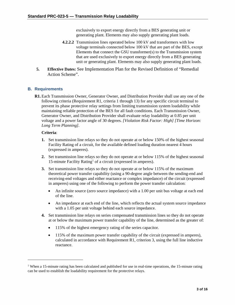
Standard PRC-023-5 — Transmission Relay Loadability
3 of 16
exclusively to export energy directly from a BES generating unit or generating plant. Elements may also supply generating plant loads.
4.2.2.2 Transmission lines operated below 100 kV and transformers with low voltage terminals connected below 100 kV that are part of the BES, except Elements that connect the GSU transformer(s) to the Transmission system that are used exclusively to export energy directly from a BES generating unit or generating plant. Elements may also supply generating plant loads.
5. Effective Dates: See Implementation Plan for the Revised Definition of “Remedial Action Scheme”.
B. Requirements R1. Each Transmission Owner, Generator Owner, and Distribution Provider shall use any one of the
following criteria (Requirement R1, criteria 1 through 13) for any specific circuit terminal to prevent its phase protective relay settings from limiting transmission system loadability while maintaining reliable protection of the BES for all fault conditions. Each Transmission Owner, Generator Owner, and Distribution Provider shall evaluate relay loadability at 0.85 per unit voltage and a power factor angle of 30 degrees. [Violation Risk Factor: High] [Time Horizon: Long Term Planning].
Criteria:
1. Set transmission line relays so they do not operate at or below 150% of the highest seasonal Facility Rating of a circuit, for the available defined loading duration nearest 4 hours (expressed in amperes).
2. Set transmission line relays so they do not operate at or below 115% of the highest seasonal 15-minute Facility Rating1 of a circuit (expressed in amperes).
3. Set transmission line relays so they do not operate at or below 115% of the maximum theoretical power transfer capability (using a 90-degree angle between the sending-end and receiving-end voltages and either reactance or complex impedance) of the circuit (expressed in amperes) using one of the following to perform the power transfer calculation:
• An infinite source (zero source impedance) with a 1.00 per unit bus voltage at each end of the line.
• An impedance at each end of the line, which reflects the actual system source impedance with a 1.05 per unit voltage behind each source impedance.
4. Set transmission line relays on series compensated transmission lines so they do not operate at or below the maximum power transfer capability of the line, determined as the greater of:
• 115% of the highest emergency rating of the series capacitor.
• 115% of the maximum power transfer capability of the circuit (expressed in amperes), calculated in accordance with Requirement R1, criterion 3, using the full line inductive reactance.
1 When a 15-minute rating has been calculated and published for use in real-time operations, the 15-minute rating can be used to establish the loadability requirement for the protective relays.

Standard PRC-023-5 — Transmission Relay Loadability
4 of 16
5. Set transmission line relays on weak source systems so they do not operate at or below 170% of the maximum end-of-line three-phase fault magnitude (expressed in amperes).
6. Not used.
7. Set transmission line relays applied at the load center terminal, remote from generation stations, so they do not operate at or below 115% of the maximum current flow from the load to the generation source under any system configuration.
8. Set transmission line relays applied on the bulk system-end of transmission lines that serve load remote to the system so they do not operate at or below 115% of the maximum current flow from the system to the load under any system configuration.
9. Set transmission line relays applied on the load-end of transmission lines that serve load remote to the bulk system so they do not operate at or below 115% of the maximum current flow from the load to the system under any system configuration.
10. Set transformer fault protection relays and transmission line relays on transmission lines terminated only with a transformer so that the relays do not operate at or below the greater of:
• 150% of the applicable maximum transformer nameplate rating (expressed in amperes), including the forced cooled ratings corresponding to all installed supplemental cooling equipment.
• 115% of the highest operator established emergency transformer rating.
10.1 Set load-responsive transformer fault protection relays, if used, such that the protection settings do not expose the transformer to a fault level and duration that exceeds the transformer’s mechanical withstand capability2.
11. For transformer overload protection relays that do not comply with the loadability component of Requirement R1, criterion 10 set the relays according to one of the following:
• Set the relays to allow the transformer to be operated at an overload level of at least 150% of the maximum applicable nameplate rating, or 115% of the highest operator established emergency transformer rating, whichever is greater, for at least 15 minutes to provide time for the operator to take controlled action to relieve the overload.
• Install supervision for the relays using either a top oil or simulated winding hot spot temperature element set no less than 100° C for the top oil temperature or no less than 140° C for the winding hot spot temperature3.
12. When the desired transmission line capability is limited by the requirement to adequately protect the transmission line, set the transmission line distance relays to a maximum of 125% of the apparent impedance (at the impedance angle of the transmission line) subject to the following constraints:
a. Set the maximum torque angle (MTA) to 90 degrees or the highest supported by the manufacturer.
2 As illustrated by the “dotted line” in IEEE C57.109-1993 - IEEE Guide for Liquid-Immersed Transformer Through-Fault-Current Duration, Clause 4.4, Figure 4.
3 IEEE standard C57.91, Tables 7 and 8, specify that transformers are to be designed to withstand a winding hot spot temperature of 180 degrees C, and Annex A cautions that bubble formation may occur above 140 degrees C.

Standard PRC-023-5 — Transmission Relay Loadability
5 of 16
b. Evaluate the relay loadability in amperes at the relay trip point at 0.85 per unit voltage and a power factor angle of 30 degrees.
c. Include a relay setting component of 87% of the current calculated in Requirement R1, criterion 12 in the Facility Rating determination for the circuit.
13. Where other situations present practical limitations on circuit capability, set the phase protection relays so they do not operate at or below 115% of such limitations.
R2. Each Transmission Owner, Generator Owner, and Distribution Provider shall set its out-of-step blocking elements to allow tripping of phase protective relays for faults that occur during the loading conditions used to verify transmission line relay loadability per Requirement R1. [Violation Risk Factor: High] [Time Horizon: Long Term Planning]
R3. Each Transmission Owner, Generator Owner, and Distribution Provider that uses a circuit capability with the practical limitations described in Requirement R1, criterion 7, 8, 9, 12, or 13 shall use the calculated circuit capability as the Facility Rating of the circuit and shall obtain the agreement of the Planning Coordinator, Transmission Operator, and Reliability Coordinator with the calculated circuit capability. [Violation Risk Factor: Medium] [Time Horizon: Long Term Planning]
R4. Each Transmission Owner, Generator Owner, and Distribution Provider that chooses to use Requirement R1 criterion 2 as the basis for verifying transmission line relay loadability shall provide its Planning Coordinator, Transmission Operator, and Reliability Coordinator with an updated list of circuits associated with those transmission line relays at least once each calendar year, with no more than 15 months between reports. [Violation Risk Factor: Lower] [Time Horizon: Long Term Planning]
R5. Each Transmission Owner, Generator Owner, and Distribution Provider that sets transmission line relays according to Requirement R1 criterion 12 shall provide an updated list of the circuits associated with those relays to its Regional Entity at least once each calendar year, with no more than 15 months between reports, to allow the ERO to compile a list of all circuits that have protective relay settings that limit circuit capability. [Violation Risk Factor: Lower] [Time Horizon: Long Term Planning]
R6. Each Planning Coordinator shall conduct an assessment at least once each calendar year, with no more than 15 months between assessments, by applying the criteria in PRC-023-4, Attachment B to determine the circuits in its Planning Coordinator area for which Transmission Owners, Generator Owners, and Distribution Providers must comply with Requirements R1 through R5. The Planning Coordinator shall: [Violation Risk Factor: High] [Time Horizon: Long Term Planning]
6.1 Maintain a list of circuits subject to PRC-023-4 per application of Attachment B, including identification of the first calendar year in which any criterion in PRC-023-4, Attachment B applies.
6.2 Provide the list of circuits to all Regional Entities, Reliability Coordinators, Transmission Owners, Generator Owners, and Distribution Providers within its Planning Coordinator area within 30 calendar days of the establishment of the initial list and within 30 calendar days of any changes to that list.
C. Measures M1. Each Transmission Owner, Generator Owner, and Distribution Provider shall have evidence
such as spreadsheets or summaries of calculations to show that each of its transmission relays is

Standard PRC-023-5 — Transmission Relay Loadability
6 of 16
set according to one of the criteria in Requirement R1, criterion 1 through 13 and shall have evidence such as coordination curves or summaries of calculations that show that relays set per criterion 10 do not expose the transformer to fault levels and durations beyond those indicated in the standard. (R1)
M2. Each Transmission Owner, Generator Owner, and Distribution Provider shall have evidence such as spreadsheets or summaries of calculations to show that each of its out-of-step blocking elements is set to allow tripping of phase protective relays for faults that occur during the loading conditions used to verify transmission line relay loadability per Requirement R1. (R2)
M3. Each Transmission Owner, Generator Owner, and Distribution Provider with transmission relays set according to Requirement R1, criterion 7, 8, 9, 12, or 13 shall have evidence such as Facility Rating spreadsheets or Facility Rating database to show that it used the calculated circuit capability as the Facility Rating of the circuit and evidence such as dated correspondence that the resulting Facility Rating was agreed to by its associated Planning Coordinator, Transmission Operator, and Reliability Coordinator. (R3)
M4. Each Transmission Owner, Generator Owner, or Distribution Provider that sets transmission line relays according to Requirement R1, criterion 2 shall have evidence such as dated correspondence to show that it provided its Planning Coordinator, Transmission Operator, and Reliability Coordinator with an updated list of circuits associated with those transmission line relays within the required timeframe. The updated list may either be a full list, a list of incremental changes to the previous list, or a statement that there are no changes to the previous list. (R4)
M5. Each Transmission Owner, Generator Owner, or Distribution Provider that sets transmission line relays according to Requirement R1, criterion 12 shall have evidence such as dated correspondence that it provided an updated list of the circuits associated with those relays to its Regional Entity within the required timeframe. The updated list may either be a full list, a list of incremental changes to the previous list, or a statement that there are no changes to the previous list. (R5)
M6. Each Planning Coordinator shall have evidence such as power flow results, calculation summaries, or study reports that it used the criteria established within PRC-023-4, Attachment B to determine the circuits in its Planning Coordinator area for which applicable entities must comply with the standard as described in Requirement R6. The Planning Coordinator shall have a dated list of such circuits and shall have evidence such as dated correspondence that it provided the list to the Regional Entities, Reliability Coordinators, Transmission Owners, Generator Owners, and Distribution Providers within its Planning Coordinator area within the required timeframe. (R6)
D. Compliance 1. Compliance Monitoring Process
1.1. Compliance Enforcement Authority
As defined in the NERC Rules of Procedure, “Compliance Enforcement Authority” means NERC or the Regional Entity in their respective roles of monitoring and enforcing compliance with the NERC Reliability Standards.
1.2. Data Retention

Standard PRC-023-5 — Transmission Relay Loadability
7 of 16
The Transmission Owner, Generator Owner, Distribution Provider and Planning Coordinator shall keep data or evidence to show compliance as identified below unless directed by its Compliance Enforcement Authority to retain specific evidence for a longer period of time as part of an investigation:
The Transmission Owner, Generator Owner, and Distribution Provider shall each retain documentation to demonstrate compliance with Requirements R1 through R5 for three calendar years.
The Planning Coordinator shall retain documentation of the most recent review process required in Requirement R6. The Planning Coordinator shall retain the most recent list of circuits in its Planning Coordinator area for which applicable entities must comply with the standard, as determined per Requirement R6.
If a Transmission Owner, Generator Owner, Distribution Provider, or Planning Coordinator is found non-compliant, it shall keep information related to the non-compliance until found compliant or for the time specified above, whichever is longer.
The Compliance Enforcement Authority shall keep the last audit record and all requested and submitted subsequent audit records.
1.3. Compliance Monitoring and Assessment Processes
• Compliance Audit
• Self-Certification
• Spot Checking
• Compliance Violation Investigation
• Self-Reporting
• Complaint
1.4. Additional Compliance Information
None.

Standard PRC-023-5 — Transmission Relay Loadability
8 of 16
2. Violation Severity Levels:
Requirement Lower Moderate High Severe
R1 N/A N/A N/A
The responsible entity did not use any one of the following criteria (Requirement R1 criterion 1 through 13) for any specific circuit terminal to prevent its phase protective relay settings from limiting transmission system loadability while maintaining reliable protection of the BES for all fault conditions.
OR
The responsible entity did not evaluate relay loadability at 0.85 per unit voltage and a power factor angle of 30 degrees.
R2 N/A N/A N/A
The responsible entity failed to ensure that its out-of-step blocking elements allowed tripping of phase protective relays for faults that occur during the loading conditions used to verify transmission line relay loadability per Requirement R1.
R3 N/A N/A N/A
The responsible entity that uses a circuit capability with the practical limitations described in Requirement R1 criterion 7, 8, 9, 12, or 13 did not use the calculated circuit capability as the Facility Rating of the circuit.

Standard PRC-023-5 — Transmission Relay Loadability
9 of 16
Requirement Lower Moderate High Severe
OR
The responsible entity did not obtain the agreement of the Planning Coordinator, Transmission Operator, and Reliability Coordinator with the calculated circuit capability.
R4 N/A N/A N/A
The responsible entity did not provide its Planning Coordinator, Transmission Operator, and Reliability Coordinator with an updated list of circuits that have transmission line relays set according to the criteria established in Requirement R1 criterion 2 at least once each calendar year, with no more than 15 months between reports.
R5 N/A N/A N/A
The responsible entity did not provide its Regional Entity, with an updated list of circuits that have transmission line relays set according to the criteria established in Requirement R1 criterion 12 at least once each calendar year, with no more than 15 months between reports.
R6 N/A
The Planning Coordinator used the criteria established within Attachment B to determine the circuits in its Planning Coordinator area for which applicable entities must comply with the standard and met parts 6.1 and 6.2, but more
The Planning Coordinator used the criteria established within Attachment B to determine the circuits in its Planning Coordinator area for which applicable entities must comply with the standard and met parts 6.1 and 6.2, but 24
The Planning Coordinator failed to use the criteria established within Attachment B to determine the circuits in its Planning Coordinator area for which applicable entities must comply with the standard.

Standard PRC-023-5 — Transmission Relay Loadability
10 of 16
Requirement Lower Moderate High Severe
than 15 months and less than 24 months lapsed between assessments.
OR
The Planning Coordinator used the criteria established within Attachment B at least once each calendar year, with no more than 15 months between assessments to determine the circuits in its Planning Coordinator area for which applicable entities must comply with the standard and met 6.1 and 6.2 but failed to include the calendar year in which any criterion in Attachment B first applies.
OR
The Planning Coordinator used the criteria established within Attachment B at least once each calendar year, with no more than 15 months between assessments to determine the circuits in its Planning Coordinator area for which applicable entities must comply with the standard and met 6.1 and 6.2 but provided the list of circuits to the Reliability Coordinators, Transmission Owners, Generator Owners, and Distribution Providers within its Planning Coordinator area between 31 days and 45 days after
months or more lapsed between assessments.
OR
The Planning Coordinator used the criteria established within Attachment B at least once each calendar year, with no more than 15 months between assessments to determine the circuits in its Planning Coordinator area for which applicable entities must comply with the standard and met 6.1 and 6.2 but provided the list of circuits to the Reliability Coordinators, Transmission Owners, Generator Owners, and Distribution Providers within its Planning Coordinator area between 46 days and 60 days after list was established or updated. (part 6.2)
OR
The Planning Coordinator used the criteria established within Attachment B, at least once each calendar year, with no more than 15 months between assessments to determine the circuits in its Planning Coordinator area for which applicable entities must comply with the standard but failed to meet parts 6.1 and 6.2.
OR
The Planning Coordinator used the criteria established within Attachment B at least once each calendar year, with no more than 15 months between assessments to determine the circuits in its Planning Coordinator area for which applicable entities must comply with the standard but failed to maintain the list of circuits determined according to the process described in Requirement R6. (part 6.1)
OR
The Planning Coordinator used the criteria established within Attachment B at least once each calendar year, with no more than 15 months between assessments to determine the circuits in its Planning Coordinator area for which applicable entities must comply with the standard and met

Standard PRC-023-5 — Transmission Relay Loadability
11 of 16
Requirement Lower Moderate High Severe
the list was established or updated. (part 6.2)
6.1 but failed to provide the list of circuits to the Reliability Coordinators, Transmission Owners, Generator Owners, and Distribution Providers within its Planning Coordinator area or provided the list more than 60 days after the list was established or updated. (part 6.2)
OR
The Planning Coordinator failed to determine the circuits in its Planning Coordinator area for which applicable entities must comply with the standard.

Standard PRC-023-5 — Transmission Relay Loadability
12 of 16
E. Regional Differences None.
F. Supplemental Technical Reference Document 1. The following document is an explanatory supplement to the standard. It provides the technical
rationale underlying the requirements in this standard. The reference document contains methodology examples for illustration purposes it does not preclude other technically comparable methodologies.
“Determination and Application of Practical Relaying Loadability Ratings,” Version 1.0, June 2008, prepared by the System Protection and Control Task Force of the NERC Planning Committee, available at: http://www.nerc.com/fileUploads/File/Standards/Relay_Loadability_Reference_Doc_Clean_Final_2008July3.pdf
Version History
Version Date Action Change Tracking
1 February 12, 2008
Approved by Board of Trustees New
1 March 19, 2008 Corrected typo in last sentence of Severe VSL for Requirement 3 — “then” should be “than.”
Errata
1 March 18, 2010 Approved by FERC
1 Filed for approval April 19, 2010
Changed VRF for R3 from Medium to High; changed VSLs for R1, R2, R3 to binary Severe to comply with Order 733
Revision
2 March 10, 2011 approved by Board of Trustees
Revised to address initial set of directives from Order 733
Revision (Project 2010-13)
2 March 15, 2012 FERC order issued approving PRC-023-2 (approval becomes effective May 7, 2012)
3 November 7, 2013
Adopted by NERC Board of Trustees Supplemental SAR to Clarify applicability for consistency with PRC-025-1 and other minor corrections.

Standard PRC-023-5 — Transmission Relay Loadability
13 of 16
Version Date Action Change Tracking
4 November 13, 2014
Adopted by the NERC Board of Trustees Replaced references to Special Protection System and SPS with Remedial Action Scheme and RAS
4 November 19, 2015
FERC Order issued approving PRC-023-4. Docket No. RM15-13-000.

Standard PRC-023-5 — Transmission Relay Loadability
14 of 16
PRC-023-4 — Attachment A 1. This standard includes any protective functions which could trip with or without time delay, on load
current, including but not limited to:
1.1. Phase distance.
1.2. Out-of-step tripping.
1.3. Switch-on-to-fault.
1.4. Overcurrent relays.
1.5. Communications aided protection schemes including but not limited to:
1.5.1 Permissive overreach transfer trip (POTT).
1.5.2 Permissive under-reach transfer trip (PUTT).
1.5.3 Directional comparison blocking (DCB).
1.5.4 Directional comparison unblocking (DCUB).
1.6. Phase overcurrent supervisory elements (i.e., phase fault detectors) associated with current-based, communication-assisted schemes (i.e., pilot wire, phase comparison, and line current differential) where the scheme is capable of tripping for loss of communications.
2. The following protection systems are excluded from requirements of this standard:
2.1. Relay elements that are only enabled when other relays or associated systems fail. For example:
• Overcurrent elements that are only enabled during loss of potential conditions.
• Elements that are only enabled during a loss of communications except as noted in section 1.6.
2.2. Protection systems intended for the detection of ground fault conditions.
2.3. Protection systems intended for protection during stable power swings.
2.4. Not used.
2.5. Relay elements used only for Remedial Action Schemes applied and approved in accordance with NERC Reliability Standards PRC-012 through PRC-017 or their successors.
2.6. Protection systems that are designed only to respond in time periods which allow 15 minutes or greater to respond to overload conditions.
2.7. Thermal emulation relays which are used in conjunction with dynamic Facility Ratings.
2.8. Relay elements associated with dc lines.
2.9. Relay elements associated with dc converter transformers.

Standard PRC-023-5 — Transmission Relay Loadability
15 of 16
PRC-023-4 — Attachment B Circuits to Evaluate
• Transmission lines operated at 100 kV to 200 kV and transformers with low voltage terminals connected at 100 kV to 200 kV.
• Transmission lines operated below 100 kV and transformers with low voltage terminals connected below 100 kV that are part of the Bulk Electric System.
Criteria
If any of the following criteria apply to a circuit, the applicable entity must comply with the standard for that circuit.
B1. The circuit is a monitored Facility of a permanent flowgate in the Eastern Interconnection, a major transfer path within the Western Interconnection as defined by the Regional Entity, or a comparable monitored Facility in the Québec Interconnection, that has been included to address reliability concerns for loading of that circuit, as confirmed by the applicable Planning Coordinator.
B2. The circuit is selected by the Planning Coordinator based on Planning Assessments that identify instances of instability, Cascading, or uncontrolled separation.
B3. The circuit forms a path (as agreed to by the Generator Operator and the transmission entity) to supply off-site power to a nuclear plant as established in the Nuclear Plant Interface Requirements (NPIRs) pursuant to NUC-001.
B4. The circuit is identified through the following sequence of power flow analyses4 performed by the Planning Coordinator for the one-to-five-year planning horizon:
a. Simulate double contingency combinations selected by engineering judgment, without manual system adjustments in between the two contingencies (reflects a situation where a System Operator may not have time between the two contingencies to make appropriate system adjustments).
b. For circuits operated between 100 kV and 200 kV evaluate the post-contingency loading, in consultation with the Facility owner, against a threshold based on the Facility Rating assigned for that circuit and used in the power flow case by the Planning Coordinator.
c. When more than one Facility Rating for that circuit is available in the power flow case, the threshold for selection will be based on the Facility Rating for the loading duration nearest four hours.
4 Past analyses may be used to support the assessment if no material changes to the system have occurred since the last assessment

Standard PRC-023-5 — Transmission Relay Loadability
16 of 16
d. The threshold for selection of the circuit will vary based on the loading duration assumed in the development of the Facility Rating.
i. If the Facility Rating is based on a loading duration of up to and including four hours, the circuit must comply with the standard if the loading exceeds 115% of the Facility Rating.
ii. If the Facility Rating is based on a loading duration greater than four and up to and including eight hours, the circuit must comply with the standard if the loading exceeds 120% of the Facility Rating.
iii. If the Facility Rating is based on a loading duration of greater than eight hours, the circuit must comply with the standard if the loading exceeds 130% of the Facility Rating.
e. Radially operated circuits serving only load are excluded.
B5. The circuit is selected by the Planning Coordinator based on technical studies or assessments, other than those specified in criteria B1 through B4, in consultation with the Facility owner.
B6. The circuit is mutually agreed upon for inclusion by the Planning Coordinator and the Facility owner.

Standard PRC-023-54 — Transmission Relay Loadability
1 of 16
Standard Development Timeline
This section is maintained by the drafting team during the development of the standard and will be removed when the standard is adopted by the Board of Trustees.
Description of Current Draft
Completed Actions Date
Standards Committee approved Standard Authorization Request (SAR) for posting
08/19/15
SAR posted for comment 08/20/15 – 09/21/15
Anticipated Actions Date
45-day formal comment period with initial ballot June 2018 – July 2018
10-day final ballot September 2018
NERC Board adoption November 2018
Agenda Item 5(v)(a)Standards CommitteeJuly 18, 2018

Standard PRC-023-54 — Transmission Relay Loadability
2 of 16
A. Introduction 1. Title: Transmission Relay Loadability
2. Number: PRC-023-54
3. Purpose: Protective relay settings shall not limit transmission loadability; not interfere with system operators’ ability to take remedial action to protect system reliability and; be set to reliably detect all fault conditions and protect the electrical network from these faults.
4. Applicability:
4.1. Functional Entity:
4.1.1 Transmission Owner with load-responsive phase protection systems as described in PRC-023-4 - Attachment A, applied at the terminals of the circuits defined in 4.2.1 (Circuits Subject to Requirements R1 – R5).
4.1.2 Generator Owner with load-responsive phase protection systems as described in PRC-023-4 - Attachment A, applied at the terminals of the circuits defined in 4.2.1 (Circuits Subject to Requirements R1 – R5).
4.1.3 Distribution Provider with load-responsive phase protection systems as described in PRC-023-4 - Attachment A, applied at the terminals of the circuits defined in 4.2.1 (Circuits Subject to Requirements R1 – R5), provided those circuits have bi-directional flow capabilities.
4.1.4 Planning Coordinator
4.2. Circuits:
4.2.1 Circuits Subject to Requirements R1 – R5:
4.2.1.1 Transmission lines operated at 200 kV and above, except Elements that connect the GSU transformer(s) to the Transmission system that are used exclusively to export energy directly from a BES generating unit or generating plant. Elements may also supply generating plant loads.
4.2.1.2 Transmission lines operated at 100 kV to 200 kV selected by the Planning Coordinator in accordance with Requirement R6.
4.2.1.3 Transmission lines operated below 100 kV that are part of the BES and selected by the Planning Coordinator in accordance with Requirement R6.
4.2.1.4 Transformers with low voltage terminals connected at 200 kV and above.
4.2.1.5 Transformers with low voltage terminals connected at 100 kV to 200 kV selected by the Planning Coordinator in accordance with Requirement R6.
4.2.1.6 Transformers with low voltage terminals connected below 100 kV that are part of the BES and selected by the Planning Coordinator in accordance with Requirement R6.
4.2.2 Circuits Subject to Requirement R6:
4.2.2.1 Transmission lines operated at 100 kV to 200 kV and transformers with low voltage terminals connected at 100 kV to 200 kV, except Elements that connect the GSU transformer(s) to the Transmission system that are used

Standard PRC-023-54 — Transmission Relay Loadability
3 of 16
exclusively to export energy directly from a BES generating unit or generating plant. Elements may also supply generating plant loads.
4.2.2.2 Transmission lines operated below 100 kV and transformers with low voltage terminals connected below 100 kV that are part of the BES, except Elements that connect the GSU transformer(s) to the Transmission system that are used exclusively to export energy directly from a BES generating unit or generating plant. Elements may also supply generating plant loads.
5. Effective Dates: See Implementation Plan for the Revised Definition of “Remedial Action Scheme”.
B. Requirements R1. Each Transmission Owner, Generator Owner, and Distribution Provider shall use any one of the
following criteria (Requirement R1, criteria 1 through 13) for any specific circuit terminal to prevent its phase protective relay settings from limiting transmission system loadability while maintaining reliable protection of the BES for all fault conditions. Each Transmission Owner, Generator Owner, and Distribution Provider shall evaluate relay loadability at 0.85 per unit voltage and a power factor angle of 30 degrees. [Violation Risk Factor: High] [Time Horizon: Long Term Planning].
Criteria:
1. Set transmission line relays so they do not operate at or below 150% of the highest seasonal Facility Rating of a circuit, for the available defined loading duration nearest 4 hours (expressed in amperes).
2. Set transmission line relays so they do not operate at or below 115% of the highest seasonal 15-minute Facility Rating1 of a circuit (expressed in amperes).
3. Set transmission line relays so they do not operate at or below 115% of the maximum theoretical power transfer capability (using a 90-degree angle between the sending-end and receiving-end voltages and either reactance or complex impedance) of the circuit (expressed in amperes) using one of the following to perform the power transfer calculation:
• An infinite source (zero source impedance) with a 1.00 per unit bus voltage at each end of the line.
• An impedance at each end of the line, which reflects the actual system source impedance with a 1.05 per unit voltage behind each source impedance.
4. Set transmission line relays on series compensated transmission lines so they do not operate at or below the maximum power transfer capability of the line, determined as the greater of:
• 115% of the highest emergency rating of the series capacitor.
• 115% of the maximum power transfer capability of the circuit (expressed in amperes), calculated in accordance with Requirement R1, criterion 3, using the full line inductive reactance.
1 When a 15-minute rating has been calculated and published for use in real-time operations, the 15-minute rating can be used to establish the loadability requirement for the protective relays.

Standard PRC-023-54 — Transmission Relay Loadability
4 of 16
5. Set transmission line relays on weak source systems so they do not operate at or below 170% of the maximum end-of-line three-phase fault magnitude (expressed in amperes).
6. Not used.
7. Set transmission line relays applied at the load center terminal, remote from generation stations, so they do not operate at or below 115% of the maximum current flow from the load to the generation source under any system configuration.
8. Set transmission line relays applied on the bulk system-end of transmission lines that serve load remote to the system so they do not operate at or below 115% of the maximum current flow from the system to the load under any system configuration.
9. Set transmission line relays applied on the load-end of transmission lines that serve load remote to the bulk system so they do not operate at or below 115% of the maximum current flow from the load to the system under any system configuration.
10. Set transformer fault protection relays and transmission line relays on transmission lines terminated only with a transformer so that the relays do not operate at or below the greater of:
• 150% of the applicable maximum transformer nameplate rating (expressed in amperes), including the forced cooled ratings corresponding to all installed supplemental cooling equipment.
• 115% of the highest operator established emergency transformer rating.
10.1 Set load-responsive transformer fault protection relays, if used, such that the protection settings do not expose the transformer to a fault level and duration that exceeds the transformer’s mechanical withstand capability2.
11. For transformer overload protection relays that do not comply with the loadability component of Requirement R1, criterion 10 set the relays according to one of the following:
• Set the relays to allow the transformer to be operated at an overload level of at least 150% of the maximum applicable nameplate rating, or 115% of the highest operator established emergency transformer rating, whichever is greater, for at least 15 minutes to provide time for the operator to take controlled action to relieve the overload.
• Install supervision for the relays using either a top oil or simulated winding hot spot temperature element set no less than 100° C for the top oil temperature or no less than 140° C for the winding hot spot temperature3.
12. When the desired transmission line capability is limited by the requirement to adequately protect the transmission line, set the transmission line distance relays to a maximum of 125% of the apparent impedance (at the impedance angle of the transmission line) subject to the following constraints:
a. Set the maximum torque angle (MTA) to 90 degrees or the highest supported by the manufacturer.
2 As illustrated by the “dotted line” in IEEE C57.109-1993 - IEEE Guide for Liquid-Immersed Transformer Through-Fault-Current Duration, Clause 4.4, Figure 4.
3 IEEE standard C57.91, Tables 7 and 8, specify that transformers are to be designed to withstand a winding hot spot temperature of 180 degrees C, and Annex A cautions that bubble formation may occur above 140 degrees C.

Standard PRC-023-54 — Transmission Relay Loadability
5 of 16
b. Evaluate the relay loadability in amperes at the relay trip point at 0.85 per unit voltage and a power factor angle of 30 degrees.
c. Include a relay setting component of 87% of the current calculated in Requirement R1, criterion 12 in the Facility Rating determination for the circuit.
13. Where other situations present practical limitations on circuit capability, set the phase protection relays so they do not operate at or below 115% of such limitations.
R2. Each Transmission Owner, Generator Owner, and Distribution Provider shall set its out-of-step blocking elements to allow tripping of phase protective relays for faults that occur during the loading conditions used to verify transmission line relay loadability per Requirement R1. [Violation Risk Factor: High] [Time Horizon: Long Term Planning]
R3. Each Transmission Owner, Generator Owner, and Distribution Provider that uses a circuit capability with the practical limitations described in Requirement R1, criterion 7, 8, 9, 12, or 13 shall use the calculated circuit capability as the Facility Rating of the circuit and shall obtain the agreement of the Planning Coordinator, Transmission Operator, and Reliability Coordinator with the calculated circuit capability. [Violation Risk Factor: Medium] [Time Horizon: Long Term Planning]
R4. Each Transmission Owner, Generator Owner, and Distribution Provider that chooses to use Requirement R1 criterion 2 as the basis for verifying transmission line relay loadability shall provide its Planning Coordinator, Transmission Operator, and Reliability Coordinator with an updated list of circuits associated with those transmission line relays at least once each calendar year, with no more than 15 months between reports. [Violation Risk Factor: Lower] [Time Horizon: Long Term Planning]
R5. Each Transmission Owner, Generator Owner, and Distribution Provider that sets transmission line relays according to Requirement R1 criterion 12 shall provide an updated list of the circuits associated with those relays to its Regional Entity at least once each calendar year, with no more than 15 months between reports, to allow the ERO to compile a list of all circuits that have protective relay settings that limit circuit capability. [Violation Risk Factor: Lower] [Time Horizon: Long Term Planning]
R6. Each Planning Coordinator shall conduct an assessment at least once each calendar year, with no more than 15 months between assessments, by applying the criteria in PRC-023-4, Attachment B to determine the circuits in its Planning Coordinator area for which Transmission Owners, Generator Owners, and Distribution Providers must comply with Requirements R1 through R5. The Planning Coordinator shall: [Violation Risk Factor: High] [Time Horizon: Long Term Planning]
6.1 Maintain a list of circuits subject to PRC-023-4 per application of Attachment B, including identification of the first calendar year in which any criterion in PRC-023-4, Attachment B applies.
6.2 Provide the list of circuits to all Regional Entities, Reliability Coordinators, Transmission Owners, Generator Owners, and Distribution Providers within its Planning Coordinator area within 30 calendar days of the establishment of the initial list and within 30 calendar days of any changes to that list.
C. Measures M1. Each Transmission Owner, Generator Owner, and Distribution Provider shall have evidence
such as spreadsheets or summaries of calculations to show that each of its transmission relays is

Standard PRC-023-54 — Transmission Relay Loadability
6 of 16
set according to one of the criteria in Requirement R1, criterion 1 through 13 and shall have evidence such as coordination curves or summaries of calculations that show that relays set per criterion 10 do not expose the transformer to fault levels and durations beyond those indicated in the standard. (R1)
M2. Each Transmission Owner, Generator Owner, and Distribution Provider shall have evidence such as spreadsheets or summaries of calculations to show that each of its out-of-step blocking elements is set to allow tripping of phase protective relays for faults that occur during the loading conditions used to verify transmission line relay loadability per Requirement R1. (R2)
M3. Each Transmission Owner, Generator Owner, and Distribution Provider with transmission relays set according to Requirement R1, criterion 7, 8, 9, 12, or 13 shall have evidence such as Facility Rating spreadsheets or Facility Rating database to show that it used the calculated circuit capability as the Facility Rating of the circuit and evidence such as dated correspondence that the resulting Facility Rating was agreed to by its associated Planning Coordinator, Transmission Operator, and Reliability Coordinator. (R3)
M4. Each Transmission Owner, Generator Owner, or Distribution Provider that sets transmission line relays according to Requirement R1, criterion 2 shall have evidence such as dated correspondence to show that it provided its Planning Coordinator, Transmission Operator, and Reliability Coordinator with an updated list of circuits associated with those transmission line relays within the required timeframe. The updated list may either be a full list, a list of incremental changes to the previous list, or a statement that there are no changes to the previous list. (R4)
M5. Each Transmission Owner, Generator Owner, or Distribution Provider that sets transmission line relays according to Requirement R1, criterion 12 shall have evidence such as dated correspondence that it provided an updated list of the circuits associated with those relays to its Regional Entity within the required timeframe. The updated list may either be a full list, a list of incremental changes to the previous list, or a statement that there are no changes to the previous list. (R5)
M6. Each Planning Coordinator shall have evidence such as power flow results, calculation summaries, or study reports that it used the criteria established within PRC-023-4, Attachment B to determine the circuits in its Planning Coordinator area for which applicable entities must comply with the standard as described in Requirement R6. The Planning Coordinator shall have a dated list of such circuits and shall have evidence such as dated correspondence that it provided the list to the Regional Entities, Reliability Coordinators, Transmission Owners, Generator Owners, and Distribution Providers within its Planning Coordinator area within the required timeframe. (R6)
D. Compliance 1. Compliance Monitoring Process
1.1. Compliance Enforcement Authority
As defined in the NERC Rules of Procedure, “Compliance Enforcement Authority” means NERC or the Regional Entity in their respective roles of monitoring and enforcing compliance with the NERC Reliability Standards.
1.2. Data Retention

Standard PRC-023-54 — Transmission Relay Loadability
7 of 16
The Transmission Owner, Generator Owner, Distribution Provider and Planning Coordinator shall keep data or evidence to show compliance as identified below unless directed by its Compliance Enforcement Authority to retain specific evidence for a longer period of time as part of an investigation:
The Transmission Owner, Generator Owner, and Distribution Provider shall each retain documentation to demonstrate compliance with Requirements R1 through R5 for three calendar years.
The Planning Coordinator shall retain documentation of the most recent review process required in Requirement R6. The Planning Coordinator shall retain the most recent list of circuits in its Planning Coordinator area for which applicable entities must comply with the standard, as determined per Requirement R6.
If a Transmission Owner, Generator Owner, Distribution Provider, or Planning Coordinator is found non-compliant, it shall keep information related to the non-compliance until found compliant or for the time specified above, whichever is longer.
The Compliance Enforcement Authority shall keep the last audit record and all requested and submitted subsequent audit records.
1.3. Compliance Monitoring and Assessment Processes
• Compliance Audit
• Self-Certification
• Spot Checking
• Compliance Violation Investigation
• Self-Reporting
• Complaint
1.4. Additional Compliance Information
None.

Standard PRC-023-54 — Transmission Relay Loadability
8 of 16
2. Violation Severity Levels:
Requirement Lower Moderate High Severe
R1 N/A N/A N/A
The responsible entity did not use any one of the following criteria (Requirement R1 criterion 1 through 13) for any specific circuit terminal to prevent its phase protective relay settings from limiting transmission system loadability while maintaining reliable protection of the BES for all fault conditions.
OR
The responsible entity did not evaluate relay loadability at 0.85 per unit voltage and a power factor angle of 30 degrees.
R2 N/A N/A N/A
The responsible entity failed to ensure that its out-of-step blocking elements allowed tripping of phase protective relays for faults that occur during the loading conditions used to verify transmission line relay loadability per Requirement R1.
R3 N/A N/A N/A
The responsible entity that uses a circuit capability with the practical limitations described in Requirement R1 criterion 7, 8, 9, 12, or 13 did not use the calculated circuit capability as the Facility Rating of the circuit.

Standard PRC-023-54 — Transmission Relay Loadability
9 of 16
Requirement Lower Moderate High Severe
OR
The responsible entity did not obtain the agreement of the Planning Coordinator, Transmission Operator, and Reliability Coordinator with the calculated circuit capability.
R4 N/A N/A N/A
The responsible entity did not provide its Planning Coordinator, Transmission Operator, and Reliability Coordinator with an updated list of circuits that have transmission line relays set according to the criteria established in Requirement R1 criterion 2 at least once each calendar year, with no more than 15 months between reports.
R5 N/A N/A N/A
The responsible entity did not provide its Regional Entity, with an updated list of circuits that have transmission line relays set according to the criteria established in Requirement R1 criterion 12 at least once each calendar year, with no more than 15 months between reports.
R6 N/A
The Planning Coordinator used the criteria established within Attachment B to determine the circuits in its Planning Coordinator area for which applicable entities must comply with the standard and met parts 6.1 and 6.2, but more
The Planning Coordinator used the criteria established within Attachment B to determine the circuits in its Planning Coordinator area for which applicable entities must comply with the standard and met parts 6.1 and 6.2, but 24
The Planning Coordinator failed to use the criteria established within Attachment B to determine the circuits in its Planning Coordinator area for which applicable entities must comply with the standard.

Standard PRC-023-54 — Transmission Relay Loadability
10 of 16
Requirement Lower Moderate High Severe
than 15 months and less than 24 months lapsed between assessments.
OR
The Planning Coordinator used the criteria established within Attachment B at least once each calendar year, with no more than 15 months between assessments to determine the circuits in its Planning Coordinator area for which applicable entities must comply with the standard and met 6.1 and 6.2 but failed to include the calendar year in which any criterion in Attachment B first applies.
OR
The Planning Coordinator used the criteria established within Attachment B at least once each calendar year, with no more than 15 months between assessments to determine the circuits in its Planning Coordinator area for which applicable entities must comply with the standard and met 6.1 and 6.2 but provided the list of circuits to the Reliability Coordinators, Transmission Owners, Generator Owners, and Distribution Providers within its Planning Coordinator area between 31 days and 45 days after
months or more lapsed between assessments.
OR
The Planning Coordinator used the criteria established within Attachment B at least once each calendar year, with no more than 15 months between assessments to determine the circuits in its Planning Coordinator area for which applicable entities must comply with the standard and met 6.1 and 6.2 but provided the list of circuits to the Reliability Coordinators, Transmission Owners, Generator Owners, and Distribution Providers within its Planning Coordinator area between 46 days and 60 days after list was established or updated. (part 6.2)
OR
The Planning Coordinator used the criteria established within Attachment B, at least once each calendar year, with no more than 15 months between assessments to determine the circuits in its Planning Coordinator area for which applicable entities must comply with the standard but failed to meet parts 6.1 and 6.2.
OR
The Planning Coordinator used the criteria established within Attachment B at least once each calendar year, with no more than 15 months between assessments to determine the circuits in its Planning Coordinator area for which applicable entities must comply with the standard but failed to maintain the list of circuits determined according to the process described in Requirement R6. (part 6.1)
OR
The Planning Coordinator used the criteria established within Attachment B at least once each calendar year, with no more than 15 months between assessments to determine the circuits in its Planning Coordinator area for which applicable entities must comply with the standard and met

Standard PRC-023-54 — Transmission Relay Loadability
11 of 16
Requirement Lower Moderate High Severe
the list was established or updated. (part 6.2)
6.1 but failed to provide the list of circuits to the Reliability Coordinators, Transmission Owners, Generator Owners, and Distribution Providers within its Planning Coordinator area or provided the list more than 60 days after the list was established or updated. (part 6.2)
OR
The Planning Coordinator failed to determine the circuits in its Planning Coordinator area for which applicable entities must comply with the standard.

Standard PRC-023-54 — Transmission Relay Loadability
12 of 16
E. Regional Differences None.
F. Supplemental Technical Reference Document 1. The following document is an explanatory supplement to the standard. It provides the technical
rationale underlying the requirements in this standard. The reference document contains methodology examples for illustration purposes it does not preclude other technically comparable methodologies.
“Determination and Application of Practical Relaying Loadability Ratings,” Version 1.0, June 2008, prepared by the System Protection and Control Task Force of the NERC Planning Committee, available at: http://www.nerc.com/fileUploads/File/Standards/Relay_Loadability_Reference_Doc_Clean_Final_2008July3.pdf
Version History
Version Date Action Change Tracking
1 February 12, 2008
Approved by Board of Trustees New
1 March 19, 2008 Corrected typo in last sentence of Severe VSL for Requirement 3 — “then” should be “than.”
Errata
1 March 18, 2010 Approved by FERC
1 Filed for approval April 19, 2010
Changed VRF for R3 from Medium to High; changed VSLs for R1, R2, R3 to binary Severe to comply with Order 733
Revision
2 March 10, 2011 approved by Board of Trustees
Revised to address initial set of directives from Order 733
Revision (Project 2010-13)
2 March 15, 2012 FERC order issued approving PRC-023-2 (approval becomes effective May 7, 2012)
3 November 7, 2013
Adopted by NERC Board of Trustees Supplemental SAR to Clarify applicability for consistency with PRC-025-1 and other minor corrections.

Standard PRC-023-54 — Transmission Relay Loadability
13 of 16
Version Date Action Change Tracking
4 November 13, 2014
Adopted by the NERC Board of Trustees Replaced references to Special Protection System and SPS with Remedial Action Scheme and RAS
4 November 19, 2015
FERC Order issued approving PRC-023-4. Docket No. RM15-13-000.

Standard PRC-023-54 — Transmission Relay Loadability
14 of 16
PRC-023-4 — Attachment A 1. This standard includes any protective functions which could trip with or without time delay, on load
current, including but not limited to:
1.1. Phase distance.
1.2. Out-of-step tripping.
1.3. Switch-on-to-fault.
1.4. Overcurrent relays.
1.5. Communications aided protection schemes including but not limited to:
1.5.1 Permissive overreach transfer trip (POTT).
1.5.2 Permissive under-reach transfer trip (PUTT).
1.5.3 Directional comparison blocking (DCB).
1.5.4 Directional comparison unblocking (DCUB).
1.6. Phase overcurrent supervisory elements (i.e., phase fault detectors) associated with current-based, communication-assisted schemes (i.e., pilot wire, phase comparison, and line current differential) where the scheme is capable of tripping for loss of communications.
2. The following protection systems are excluded from requirements of this standard:
2.1. Relay elements that are only enabled when other relays or associated systems fail. For example:
• Overcurrent elements that are only enabled during loss of potential conditions.
• Elements that are only enabled during a loss of communications except as noted in section 1.6.
2.2. Protection systems intended for the detection of ground fault conditions.
2.3. Protection systems intended for protection during stable power swings.
2.4. Not used.
2.5. Relay elements used only for Remedial Action Schemes applied and approved in accordance with NERC Reliability Standards PRC-012 through PRC-017 or their successors.
2.6. Protection systems that are designed only to respond in time periods which allow 15 minutes or greater to respond to overload conditions.
2.7. Thermal emulation relays which are used in conjunction with dynamic Facility Ratings.
2.8. Relay elements associated with dc lines.
2.9. Relay elements associated with dc converter transformers.

Standard PRC-023-54 — Transmission Relay Loadability
15 of 16
PRC-023-4 — Attachment B Circuits to Evaluate
• Transmission lines operated at 100 kV to 200 kV and transformers with low voltage terminals connected at 100 kV to 200 kV.
• Transmission lines operated below 100 kV and transformers with low voltage terminals connected below 100 kV that are part of the Bulk Electric System.
Criteria
If any of the following criteria apply to a circuit, the applicable entity must comply with the standard for that circuit.
B1. The circuit is a monitored Facility of a permanent flowgate in the Eastern Interconnection, a major transfer path within the Western Interconnection as defined by the Regional Entity, or a comparable monitored Facility in the Québec Interconnection, that has been included to address reliability concerns for loading of that circuit, as confirmed by the applicable Planning Coordinator.
B2. The circuit is selected by the Planning Coordinator based on Planning Assessments that identify instances of instability, Cascading, or uncontrolled separation.
B2. The circuit is a monitored Facility of an Interconnection Reliability Operating Limit (IROL), where the IROL was determined in the planning horizon pursuant to FAC-010.
B3. The circuit forms a path (as agreed to by the Generator Operator and the transmission entity) to supply off-site power to a nuclear plant as established in the Nuclear Plant Interface Requirements (NPIRs) pursuant to NUC-001.
B4. The circuit is identified through the following sequence of power flow analyses4 performed by the Planning Coordinator for the one-to-five-year planning horizon:
a. Simulate double contingency combinations selected by engineering judgment, without manual system adjustments in between the two contingencies (reflects a situation where a System Operator may not have time between the two contingencies to make appropriate system adjustments).
b. For circuits operated between 100 kV and 200 kV evaluate the post-contingency loading, in consultation with the Facility owner, against a threshold based on the Facility Rating assigned for that circuit and used in the power flow case by the Planning Coordinator.
4 Past analyses may be used to support the assessment if no material changes to the system have occurred since the last assessment

Standard PRC-023-54 — Transmission Relay Loadability
16 of 16
c. When more than one Facility Rating for that circuit is available in the power flow case, the threshold for selection will be based on the Facility Rating for the loading duration nearest four hours.
d. The threshold for selection of the circuit will vary based on the loading duration assumed in the development of the Facility Rating.
i. If the Facility Rating is based on a loading duration of up to and including four hours, the circuit must comply with the standard if the loading exceeds 115% of the Facility Rating.
ii. If the Facility Rating is based on a loading duration greater than four and up to and including eight hours, the circuit must comply with the standard if the loading exceeds 120% of the Facility Rating.
iii. If the Facility Rating is based on a loading duration of greater than eight hours, the circuit must comply with the standard if the loading exceeds 130% of the Facility Rating.
e. Radially operated circuits serving only load are excluded.
B5. The circuit is selected by the Planning Coordinator based on technical studies or assessments, other than those specified in criteria B1 through B4, in consultation with the Facility owner.
B6. The circuit is mutually agreed upon for inclusion by the Planning Coordinator and the Facility owner.

PRC-026-2 — Relay Performance During Stable Power Swings
Page 1 of 85
Standard Development Timeline
This section is maintained by the drafting team during the development of the standard and will be removed when the standard is adopted by the Board of Trustees.
Description of Current Draft
Completed Actions Date
Standards Committee approved Standard Authorization Request (SAR) for posting
08/19/15
SAR posted for comment 08/20/15 – 09/21/15
Anticipated Actions Date
45-day formal comment period with initial ballot June 2018 – July 2018
10-day final ballot September 2018
NERC Board adoption November 2018
Agenda Item 5(vi)Standards CommitteeJuly 18, 2018

PRC-026-2 — Relay Performance During Stable Power Swings
Page 2 of 85
A. Introduction 1. Title: Relay Performance During Stable Power Swings 2. Number: PRC-026-2 3. Purpose: To ensure that load-responsive protective relays are expected to not trip in
response to stable power swings during non-Fault conditions.
4. Applicability: 4.1. Functional Entities:
4.1.1 Generator Owner that applies load-responsive protective relays as described in PRC-026-1 – Attachment A at the terminals of the Elements listed in Section 4.2, Facilities.
4.1.2 Planning Coordinator.
4.1.3 Transmission Owner that applies load-responsive protective relays as described in PRC-026-1 – Attachment A at the terminals of the Elements listed in Section 4.2, Facilities.
4.2. Facilities: The following Elements that are part of the Bulk Electric System (BES): 4.2.1 Generators.
4.2.2 Transformers.
4.2.3 Transmission lines.
5. Background: This is the third phase of a three-phased standard development project that focused on developing this new Reliability Standard to address protective relay operations due to stable power swings. The March 18, 2010, Federal Energy Regulatory Commission (FERC) Order No. 733 approved Reliability Standard PRC-023-1 – Transmission Relay Loadability. In that Order, FERC directed NERC to address three areas of relay loadability that include modifications to the approved PRC-023-1, development of a new Reliability Standard to address generator protective relay loadability, and a new Reliability Standard to address the operation of protective relays due to stable power swings. This project’s SAR addresses these directives with a three-phased approach to standard development.
Phase 1 focused on making the specific modifications from FERC Order No. 733 to PRC-023-1. Reliability Standard PRC-023-2, which incorporated these modifications, became mandatory on July 1, 2012.
Phase 2 focused on developing a new Reliability Standard, PRC-025-1 – Generator Relay Loadability, to address generator protective relay loadability. PRC-025-1 became mandatory on October 1, 2014, along with PRC-023-3, which was modified to harmonize PRC-023-2 with PRC-025-1.
Phase 3 focuses on preventing protective relays from tripping unnecessarily due to stable power swings by requiring identification of Elements on which a stable or unstable power

PRC-026-2 — Relay Performance During Stable Power Swings
Page 3 of 85
swing may affect Protection System operation, assessment of the security of load-responsive protective relays to tripping in response to only a stable power swing, and implementation of Corrective Action Plans (CAP), where necessary. Phase 3 improves security of load-responsive protective relays for stable power swings so they are expected to not trip in response to stable power swings during non-Fault conditions while maintaining dependable fault detection and dependable out-of-step tripping.
6. Effective Dates: Requirement R1 First day of the first full calendar year that is 12 months after the date that the standard is approved by an applicable governmental authority or as otherwise provided for in a jurisdiction where approval by an applicable governmental authority is required for a standard to go into effect. Where approval by an applicable governmental authority is not required, the standard shall become effective on the first day of the first full calendar year that is 12 months after the date the standard is adopted by the NERC Board of Trustees or as otherwise provided for in that jurisdiction.
Requirements R2, R3, and R4 First day of the first full calendar year that is 36 months after the date that the standard is approved by an applicable governmental authority or as otherwise provided for in a jurisdiction where approval by an applicable governmental authority is required for a standard to go into effect. Where approval by an applicable governmental authority is not required, the standard shall become effective on the first day of the first full calendar year that is 36 months after the date the standard is adopted by the NERC Board of Trustees or as otherwise provided for in that jurisdiction.

PRC-026-2 — Relay Performance During Stable Power Swings
Page 4 of 85
B. Requirements and Measures R1. Each Planning Coordinator shall, at least once each calendar year, provide notification
of each generator, transformer, and transmission line BES Element in its area that meets one or more of the following criteria, if any, to the respective Generator Owner and Transmission Owner: [Violation Risk Factor: Medium] [Time Horizon: Long-term Planning]
Criteria:
1. Generator(s) where an angular stability constraint exists that is addressed by limiting the output of a generator or a Remedial Action Scheme (RAS), and those Elements terminating at the Transmission station associated with the generator(s).
2. Elements associated with angular instability identified in Planning Assessments. 3. An Element that forms the boundary of an island in the most recent
underfrequency load shedding (UFLS) design assessment based on application of the Planning Coordinator’s criteria for identifying islands, only if the island is formed by tripping the Element due to angular instability.
4. An Element identified in the most recent annual Planning Assessment where relay tripping occurs due to a stable or unstable1 power swing during a simulated disturbance.
M1. Each Planning Coordinator shall have dated evidence that demonstrates notification of the generator, transformer, and transmission line BES Element(s) that meet one or more of the criteria in Requirement R1, if any, to the respective Generator Owner and Transmission Owner. Evidence may include, but is not limited to, the following documentation: emails, facsimiles, records, reports, transmittals, lists, or spreadsheets.
1 An example of an unstable power swing is provided in the Guidelines and Technical Basis section, “Justification for Including Unstable Power Swings in the Requirements section of the Guidelines and Technical Basis.”

PRC-026-2 — Relay Performance During Stable Power Swings
Page 5 of 85
R2. Each Generator Owner and Transmission Owner shall: [Violation Risk Factor: High] [Time Horizon: Operations Planning]
2.1 Within 12 full calendar months of notification of a BES Element pursuant to Requirement R1, determine whether its load-responsive protective relay(s) applied to that BES Element meets the criteria in PRC-026-1 – Attachment B where an evaluation of that Element’s load-responsive protective relay(s) based on PRC-026-1 – Attachment B criteria has not been performed in the last five calendar years.
2.2 Within 12 full calendar months of becoming aware2 of a generator, transformer, or transmission line BES Element that tripped in response to a stable or unstable3 power swing due to the operation of its protective relay(s), determine whether its load-responsive protective relay(s) applied to that BES Element meets the criteria in PRC-026-1 – Attachment B.
M2. Each Generator Owner and Transmission Owner shall have dated evidence that demonstrates the evaluation was performed according to Requirement R2. Evidence may include, but is not limited to, the following documentation: apparent impedance characteristic plots, email, design drawings, facsimiles, R-X plots, software output, records, reports, transmittals, lists, settings sheets, or spreadsheets.
R3. Each Generator Owner and Transmission Owner shall, within six full calendar months of determining a load-responsive protective relay does not meet the PRC-026-1 – Attachment B criteria pursuant to Requirement R2, develop a Corrective Action Plan (CAP) to meet one of the following: [Violation Risk Factor: Medium] [Time Horizon: Operations Planning]
• The Protection System meets the PRC-026-1 – Attachment B criteria, while maintaining dependable fault detection and dependable out-of-step tripping (if out-of-step tripping is applied at the terminal of the BES Element); or
• The Protection System is excluded under the PRC-026-1 – Attachment A criteria (e.g., modifying the Protection System so that relay functions are supervised by power swing blocking or using relay systems that are immune to power swings), while maintaining dependable fault detection and dependable out-of-step tripping (if out-of-step tripping is applied at the terminal of the BES Element).
M3. The Generator Owner and Transmission Owner shall have dated evidence that demonstrates the development of a CAP in accordance with Requirement R3. Evidence may include, but is not limited to, the following documentation: corrective action plans, maintenance records, settings sheets, project or work management program records, or work orders.
R4. Each Generator Owner and Transmission Owner shall implement each CAP developed pursuant to Requirement R3 and update each CAP if actions or timetables change until all actions are complete. [Violation Risk Factor: Medium][Time Horizon: Long-Term Planning]

PRC-026-2 — Relay Performance During Stable Power Swings
Page 6 of 85
M4. The Generator Owner and Transmission Owner shall have dated evidence that demonstrates implementation of each CAP according to Requirement R4, including updates to the CAP when actions or timetables change. Evidence may include, but is not limited to, the following documentation: corrective action plans, maintenance records, settings sheets, project or work management program records, or work orders.
C. Compliance 1. Compliance Monitoring Process
1.1. Compliance Enforcement Authority As defined in the NERC Rules of Procedure, “Compliance Enforcement Authority” (CEA) means NERC or the Regional Entity in their respective roles of monitoring and enforcing compliance with the NERC Reliability Standards.
1.2. Evidence Retention The following evidence retention periods identify the period of time an entity is required to retain specific evidence to demonstrate compliance. For instances where the evidence retention period specified below is shorter than the time since the last audit, the CEA may ask an entity to provide other evidence to show that it was compliant for the full time period since the last audit.
The Generator Owner, Planning Coordinator, and Transmission Owner shall keep data or evidence to show compliance as identified below unless directed by its CEA to retain specific evidence for a longer period of time as part of an investigation.
• The Planning Coordinator shall retain evidence of Requirement R1 for a minimum of one calendar year following the completion of the Requirement.
• The Generator Owner and Transmission Owner shall retain evidence of Requirement R2 evaluation for a minimum of 12 calendar months following completion of each evaluation where a CAP is not developed.
• The Generator Owner and Transmission Owner shall retain evidence of Requirements R2, R3, and R4 for a minimum of 12 calendar months following completion of each CAP.
If a Generator Owner, Planning Coordinator, or Transmission Owner is found non-compliant, it shall keep information related to the non-compliance until mitigation is complete and approved, or for the time specified above, whichever is longer.
2 Some examples of the ways an entity may become aware of a power swing are provided in the Guidelines and Technical Basis section, “Becoming Aware of an Element That Tripped in Response to a Power Swing.” 3 An example of an unstable power swing is provided in the Guidelines and Technical Basis section, “Justification for Including Unstable Power Swings in the Requirements section of the Guidelines and Technical Basis.”

PRC-026-2 — Relay Performance During Stable Power Swings
Page 7 of 85
The CEA shall keep the last audit records and all requested and submitted subsequent audit records.
1.3. Compliance Monitoring and Assessment Processes: As defined in the NERC Rules of Procedure; “Compliance Monitoring and Assessment Processes” refers to the identification of the processes that will be used to evaluate data or information for the purpose of assessing performance or outcomes with the associated reliability standard.
1.4. Additional Compliance Information None.

PRC-026-2 — Relay Performance During Stable Power Swings
Page 8 of 85
Table of Compliance Elements
R# Time Horizon VRF
Violation Severity Levels
Lower VSL Moderate VSL High VSL Severe VSL
R1 Long-term Planning
Medium The Planning Coordinator provided notification of the BES Element(s) in accordance with Requirement R1, but was less than or equal to 30 calendar days late.
The Planning Coordinator provided notification of the BES Element(s) in accordance with Requirement R1, but was more than 30 calendar days and less than or equal to 60 calendar days late.
The Planning Coordinator provided notification of the BES Element(s) in accordance with Requirement R1, but was more than 60 calendar days and less than or equal to 90 calendar days late.
The Planning Coordinator provided notification of the BES Element(s) in accordance with Requirement R1, but was more than 90 calendar days late.
OR
The Planning Coordinator failed to provide notification of the BES Element(s) in accordance with Requirement R1.

PRC-026-2 — Relay Performance During Stable Power Swings
Page 9 of 85
R# Time Horizon VRF
Violation Severity Levels
Lower VSL Moderate VSL High VSL Severe VSL
R2 Operations Planning
High The Generator Owner or Transmission Owner evaluated its load-responsive protective relay(s) in accordance with Requirement R2, but was less than or equal to 30 calendar days late.
The Generator Owner or Transmission Owner evaluated its load-responsive protective relay(s) in accordance with Requirement R2, but was more than 30 calendar days and less than or equal to 60 calendar days late.
The Generator Owner or Transmission Owner evaluated its load-responsive protective relay(s) in accordance with Requirement R2, but was more than 60 calendar days and less than or equal to 90 calendar days late.
The Generator Owner or Transmission Owner evaluated its load-responsive protective relay(s) in accordance with Requirement R2, but was more than 90 calendar days late.
OR
The Generator Owner or Transmission Owner failed to evaluate its load-responsive protective relay(s) in accordance with Requirement R2.

PRC-026-2 — Relay Performance During Stable Power Swings
Page 10 of 85
R# Time Horizon VRF
Violation Severity Levels
Lower VSL Moderate VSL High VSL Severe VSL
R3 Long-term Planning
Medium The Generator Owner or Transmission Owner developed a Corrective Action Plan (CAP) in accordance with Requirement R3, but in more than six calendar months and less than or equal to seven calendar months.
The Generator Owner or Transmission Owner developed a Corrective Action Plan (CAP) in accordance with Requirement R3, but in more than seven calendar months and less than or equal to eight calendar months.
The Generator Owner or Transmission Owner developed a Corrective Action Plan (CAP) in accordance with Requirement R3, but in more than eight calendar months and less than or equal to nine calendar months.
The Generator Owner or Transmission Owner developed a Corrective Action Plan (CAP) in accordance with Requirement R3, but in more than nine calendar months.
OR
The Generator Owner or Transmission Owner failed to develop a CAP in accordance with Requirement R3.
R4 Long-term Planning
Medium The Generator Owner or Transmission Owner implemented a Corrective Action Plan (CAP), but failed to update a CAP when actions or timetables changed, in accordance with Requirement R4.
N/A N/A
The Generator Owner or Transmission Owner failed to implement a Corrective Action Plan (CAP) in accordance with Requirement R4.

PRC-026-2 — Relay Performance During Stable Power Swings
Page 11 of 85
D. Regional Variances
None.
E. Interpretations None.
F. Associated Documents Applied Protective Relaying, Westinghouse Electric Corporation, 1979.
Burdy, John, Loss-of-excitation Protection for Synchronous Generators GER-3183, General Electric Company.
IEEE Power System Relaying Committee WG D6, Power Swing and Out-of-Step Considerations on Transmission Lines, July 2005: http://www.pes-psrc.org/Reports /Power%20Swing%20and%20OOS%20Considerations%20on%20Transmission%20Lines%20F..pdf.
Kimbark Edward Wilson, Power System Stability, Volume II: Power Circuit Breakers and Protective Relays, Published by John Wiley and Sons, 1950.
Kundur, Prabha, Power System Stability and Control, 1994, Palo Alto: EPRI, McGraw Hill, Inc.
NERC System Protection and Control Subcommittee, Protection System Response to Power Swings, August 2013: http://www.nerc.com/comm/PC/System%20Protection%20 and%20Control%20Subcommittee%20SPCS%2020/SPCS%20Power%20Swing%20Report_Final_20131015.pdf.
Reimert, Donald, Protective Relaying for Power Generation Systems, 2006, Boca Raton: CRC Press.
Version History
Version Date Action Change Tracking
1 November 13, 2014 Adopted by NERC Board of Trustees
New
1 March 17, 2016 FERC Order issued approving PRC-026-1. Docket No. RM15-8-000.

PRC-026-2 — Relay Performance During Stable Power Swings
Page 12 of 85
PRC-026-1 – Attachment A This standard applies to any protective functions which could trip instantaneously or with a time delay of less than 15 cycles on load current (i.e., “load-responsive”) including, but not limited to:
• Phase distance • Phase overcurrent • Out-of-step tripping • Loss-of-field
The following protection functions are excluded from Requirements of this standard:
• Relay elements supervised by power swing blocking • Relay elements that are only enabled when other relays or associated systems fail. For
example: o Overcurrent elements that are only enabled during loss of potential conditions. o Relay elements that are only enabled during a loss of communications
• Thermal emulation relays which are used in conjunction with dynamic Facility Ratings • Relay elements associated with direct current (dc) lines • Relay elements associated with dc converter transformers • Phase fault detector relay elements employed to supervise other load-responsive phase
distance elements (i.e., in order to prevent false operation in the event of a loss of potential) • Relay elements associated with switch-onto-fault schemes • Reverse power relay on the generator • Generator relay elements that are armed only when the generator is disconnected from the
system, (e.g., non-directional overcurrent elements used in conjunction with inadvertent energization schemes, and open breaker flashover schemes)
• Current differential relay, pilot wire relay, and phase comparison relay • Voltage-restrained or voltage-controlled overcurrent relays

PRC-026-2 — Relay Performance During Stable Power Swings
Page 13 of 85
PRC-026-1 – Attachment B
Criterion A:
An impedance-based relay used for tripping is expected to not trip for a stable power swing, when the relay characteristic is completely contained within the unstable power swing region.4 The unstable power swing region is formed by the union of three shapes in the impedance (R-X) plane; (1) a lower loss-of-synchronism circle based on a ratio of the sending-end to receiving-end voltages of 0.7; (2) an upper loss-of-synchronism circle based on a ratio of the sending-end to receiving-end voltages of 1.43; (3) a lens that connects the endpoints of the total system impedance (with the parallel transfer impedance removed) bounded by varying the sending-end and receiving-end voltages from 0.0 to 1.0 per unit, while maintaining a constant system separation angle across the total system impedance where:
1. The system separation angle is: • At least 120 degrees, or • An angle less than 120 degrees where a documented transient stability analysis
demonstrates that the expected maximum stable separation angle is less than 120 degrees.
2. All generation is in service and all transmission BES Elements are in their normal operating state when calculating the system impedance.
3. Saturated (transient or sub-transient) reactance is used for all machines.
4 Guidelines and Technical Basis, Figures 1 and 2.

PRC-026-2 — Relay Performance During Stable Power Swings
Page 14 of 85
PRC-026-1 – Attachment B
Criterion B:
The pickup of an overcurrent relay element used for tripping, that is above the calculated current value (with the parallel transfer impedance removed) for the conditions below:
1. The system separation angle is: • At least 120 degrees, or • An angle less than 120 degrees where a documented transient stability analysis
demonstrates that the expected maximum stable separation angle is less than 120 degrees.
2. All generation is in service and all transmission BES Elements are in their normal operating state when calculating the system impedance.
3. Saturated (transient or sub-transient) reactance is used for all machines. 4. Both the sending-end and receiving-end voltages at 1.05 per unit.

PRC-026-2 – Application Guidelines
Page 15 of 85
Guidelines and Technical Basis
Introduction The NERC System Protection and Control Subcommittee technical document, Protection System Response to Power Swings, August 2013,5 (“PSRPS Report” or “report”) was specifically prepared to support the development of this NERC Reliability Standard. The report provided a historical perspective on power swings as early as 1965 up through the approval of the report by the NERC Planning Committee. The report also addresses reliability issues regarding trade-offs between security and dependability of Protection Systems, considerations for this NERC Reliability Standard, and a collection of technical information about power swing characteristics and varying issues with practical applications and approaches to power swings. Of these topics, the report suggests an approach for this NERC Reliability Standard (“standard” or “PRC-026-1”) which is consistent with addressing three regulatory directives in the FERC Order No. 733. The first directive concerns the need for “…protective relay systems that differentiate between faults and stable power swings and, when necessary, phases out protective relay systems that cannot meet this requirement.”6 Second, is “…to develop a Reliability Standard addressing undesirable relay operation due to stable power swings.”7 The third directive “…to consider “islanding” strategies that achieve the fundamental performance for all islands in developing the new Reliability Standard addressing stable power swings”8 was considered during development of the standard.
The development of this standard implements the majority of the approaches suggested by the report. However, it is noted that the Reliability Coordinator and Transmission Planner have not been included in the standard’s Applicability section (as suggested by the PSRPS Report). This is so that a single entity, the Planning Coordinator, may be the single source for identifying Elements according to Requirement R1. A single source will insure that multiple entities will not identify Elements in duplicate, nor will one entity fail to provide an Element because it believes the Element is being provided by another entity. The Planning Coordinator has, or has access to, the wide-area model and can correctly identify the Elements that may be susceptible to a stable or unstable power swing. Additionally, not including the Reliability Coordinator and Transmission Planner is consistent with the applicability of other relay loadability NERC Reliability Standards (e.g., PRC-023 and PRC-025). It is also consistent with the NERC Functional Model.
The phrase, “while maintaining dependable fault detection and dependable out-of-step tripping” in Requirement R3, describes that the Generator Owner and Transmission Owner are to comply with this standard while achieving its desired protection goals. Load-responsive protective relays, as addressed within this standard, may be intended to provide a variety of backup protection functions, both within the generating unit or generating plant and on the transmission system, and
5 NERC System Protection and Control Subcommittee, Protection System Response to Power Swings, August 2013: http://www.nerc.com/comm/PC/System%20Protection%20and%20Control%20Subcommittee%20SPCS%2020/SPCS%20Power%20Swing%20Report_Final_20131015.pdf) 6 Transmission Relay Loadability Reliability Standard, Order No. 733, P.150 FERC ¶ 61,221 (2010). 7 Ibid. P.153. 8 Ibid. P.162.

PRC-026-2 – Application Guidelines
Page 16 of 85
this standard is not intended to result in the loss of these protection functions. Instead, the Generator Owner and Transmission Owner must consider both the Requirements within this standard and its desired protection goals and perform modifications to its protective relays or protection philosophies as necessary to achieve both.
Power Swings The IEEE Power System Relaying Committee WG D6 developed a technical document called Power Swing and Out-of-Step Considerations on Transmission Lines (July 2005) that provides background on power swings. The following are general definitions from that document:9
Power Swing: a variation in three phase power flow which occurs when the generator rotor angles are advancing or retarding relative to each other in response to changes in load magnitude and direction, line switching, loss of generation, faults, and other system disturbances.
Pole Slip: a condition whereby a generator, or group of generators, terminal voltage angles (or phases) go past 180 degrees with respect to the rest of the connected power system.
Stable Power Swing: a power swing is considered stable if the generators do not slip poles and the system reaches a new state of equilibrium, i.e. an acceptable operating condition.
Unstable Power Swing: a power swing that will result in a generator or group of generators experiencing pole slipping for which some corrective action must be taken.
Out-of-Step Condition: Same as an unstable power swing.
Electrical System Center or Voltage Zero: it is the point or points in the system where the voltage becomes zero during an unstable power swing.
Burden to Entities The PSRPS Report provides a technical basis and approach for focusing on Protection Systems, which are susceptible to power swings, while achieving the purpose of the standard. The approach reduces the number of relays to which the PRC-026-1 Requirements would apply by first identifying the BES Element(s) on which load-responsive protective relays must be evaluated. The first step uses criteria to identify the Elements on which a Protection System is expected to be challenged by power swings. Of those Elements, the second step is to evaluate each load-responsive protective relay that is applied on each identified Element. Rather than requiring the Planning Coordinator or Transmission Planner to perform simulations to obtain information for each identified Element, the Generator Owner and Transmission Owner will reduce the need for simulation by comparing the load-responsive protective relay characteristic to specific criteria in PRC-026-1 – Attachment B.
9 http://www.pes-psrc.org/Reports/Power%20Swing%20and%20OOS%20Considerations%20on%20Transmission %20Lines%20F..pdf.

PRC-026-2 – Application Guidelines
Page 17 of 85
Applicability The standard is applicable to the Generator Owner, Planning Coordinator, and Transmission Owner entities. More specifically, the Generator Owner and Transmission Owner entities are applicable when applying load-responsive protective relays at the terminals of the applicable BES Elements. The standard is applicable to the following BES Elements: generators, transformers, and transmission lines. The Distribution Provider was considered for inclusion in the standard; however, it is not subject to the standard because this entity, by functional registration, would not own generators, transmission lines, or transformers other than load serving.
Load-responsive protective relays include any protective functions which could trip with or without time delay, on load current.
Requirement R1 The Planning Coordinator has a wide-area view and is in the position to identify what, if any, Elements meet the criteria. The criterion-based approach is consistent with the NERC System Protection and Control Subcommittee (SPCS) technical document, Protection System Response to Power Swings (August 2013),10 which recommends a focused approach to determine an at-risk Element. Identification of Elements comes from the annual Planning Assessments pursuant to the transmission planning (i.e., “TPL”) and other NERC Reliability Standards (e.g., PRC-006), and the standard is not requiring any other assessments to be performed by the Planning Coordinator. The required notification on a calendar year basis to the respective Generator Owner and Transmission Owner is sufficient because it is expected that the Planning Coordinator will make its notifications following the completion of its annual Planning Assessments. The Planning Coordinator will continue to provide notification of Elements on a calendar year basis even if a study is performed less frequently (e.g., PRC-006 – Automatic Underfrequency Load Shedding, which is five years) and has not changed. It is possible that a Planning Coordinator could utilize studies from a prior year in determining the necessary notifications pursuant to Requirement R1.
Criterion 1 The first criterion involves generator(s) where an angular stability constraint exists that is addressed by limiting the output of a generator or a Remedial Action Scheme (RAS) and those Elements terminating at the Transmission station associated with the generator(s). For example, a scheme to remove generation for specific conditions is implemented for a four-unit generating plant (1,100 MW). Two of the units are 500 MW each; one is connected to the 345 kV system and one is connected to the 230 kV system. The Transmission Owner has two 230 kV transmission lines and one 345 kV transmission line all terminating at the generating facility as well as a 345/230 kV autotransformer. The remaining 100 MW consists of two 50 MW combustion turbine (CT) units connected to four 66 kV transmission lines. The 66 kV transmission lines are not electrically joined to the 345 kV and 230 kV transmission lines at the plant site and are not subject to any generating output limitation or RAS. A stability constraint limits the output of the portion of the
10 http://www.nerc.com/comm/PC/System%20Protection%20and%20Control%20Subcommittee%20SPCS%20 20/SPCS%20Power%20Swing%20Report_Final_20131015.pdf)

PRC-026-2 – Application Guidelines
Page 18 of 85
plant affected by the RAS to 700 MW for an outage of the 345 kV transmission line. The RAS trips one of the 500 MW units to maintain stability for a loss of the 345 kV transmission line when the total output from both 500 MW units is above 700 MW. For this example, both 500 MW generating units and the associated generator step-up (GSU) transformers would be identified as Elements meeting this criterion. The 345/230 kV autotransformer, the 345 kV transmission line, and the two 230 kV transmission lines would also be identified as Elements meeting this criterion. The 50 MW combustion turbines and 66 kV transmission lines would not be identified pursuant to Criterion 1 because these Elements are not subject to any generating output limitation or RAS and do not terminate at the Transmission station associated with the generators that are subject to any generating output limitation or RAS.
Criterion 2 The second criterion involves Elements associated with angular instability identified in the Planning Assessments. For example, if Planning Assessments have identified that an angular instability could limit transfer capability on two long parallel 500 kV transmission lines to a maximum of 1,200 MW, and this limitation is based on angular instability resulting from a fault and subsequent loss of one of the two lines, then both lines would be identified as Elements meeting the criterion.
Criterion 3 The third criterion involves Elements that form the boundary of an island within an underfrequency load shedding (UFLS) design assessment. The criterion applies to islands identified based on application of the Planning Coordinator’s criteria for identifying islands, where the island is formed by tripping the Elements based on angular instability. The criterion applies if the angular instability is modeled in the UFLS design assessment, or if the boundary is identified “off-line” (i.e., the Elements are selected based on angular instability considerations, but the Elements are tripped in the UFLS design assessment without modeling the initiating angular instability). In cases where an out-of-step condition is detected and tripping is initiated at an alternate location, the criterion applies to the Element on which the power swing is detected. The criterion does not apply to islands identified based on other considerations that do not involve angular instability, such as excessive loading, Planning Coordinator area boundary tie lines, or Balancing Authority boundary tie lines.
Criterion 4 The fourth criterion involves Elements identified in the most recent annual Planning Assessment where relay tripping occurs due to a stable or unstable11 power swing during a simulated disturbance. The intent is for the Planning Coordinator to include any Element(s) where relay tripping was observed during simulations performed for the most recent annual Planning Assessment associated with the transmission planning TPL-001-4 Reliability Standard. Note that
11 Refer to the “Justification for Including Unstable Power Swings in the Requirements” section.

PRC-026-2 – Application Guidelines
Page 19 of 85
relay tripping must be assessed within those annual Planning Assessments per TPL-001-4, R4, Part 4.3.1.3, which indicates that analysis shall include the “Tripping of Transmission lines and transformers where transient swings cause Protection System operation based on generic or actual relay models.” Identifying such Elements according to Criterion 4 and notifying the respective Generator Owner and Transmission Owner will require that the owners of any load-responsive protective relay applied at the terminals of the identified Element evaluate the relay’s susceptibility to tripping in response to a stable power swing.
Planning Coordinators have the discretion to determine whether the observed tripping for a power swing in its Planning Assessments occurs for valid contingencies and system conditions. The Planning Coordinator will address tripping that is observed in transient analyses on an individual basis; therefore, the Planning Coordinator is responsible for identifying the Elements based only on simulation results that are determined to be valid.
Due to the nature of how a Planning Assessment is performed, there may be cases where a previously-identified Element is not identified in the most recent annual Planning Assessment. If so, this is acceptable because the Generator Owner and Transmission Owner would have taken action upon the initial notification of the previously identified Element. When an Element is not identified in later Planning Assessments, the risk of load-responsive protective relays tripping in response to a stable power swing during non-Fault conditions would have already been assessed under Requirement R2 and mitigated according to Requirements R3 and R4 where the relays did not meet the PRC-026-1 – Attachment B criteria. According to Requirement R2, the Generator Owner and Transmission Owner are only required to re-evaluate each load-responsive protective relay for an identified Element where the evaluation has not been performed in the last five calendar years.
Although Requirement R1 requires the Planning Coordinator to notify the respective Generator Owner and Transmission Owner of any Elements meeting one or more of the four criteria, it does not preclude the Planning Coordinator from providing additional information, such as apparent impedance characteristics, in advance or upon request, that may be useful in evaluating protective relays. Generator Owners and Transmission Owners are able to complete protective relay evaluations and perform the required actions without additional information. The standard does not include any requirement for the entities to provide information that is already being shared or exchanged between entities for operating needs. While a Requirement has not been included for the exchange of information, entities should recognize that relay performance needs to be measured against the most current information.
Requirement R2 Requirement R2 requires the Generator Owner and Transmission Owner to evaluate its load-responsive protective relays to ensure that they are expected to not trip in response to stable power swings.

PRC-026-2 – Application Guidelines
Page 20 of 85
The PRC-026-1 – Attachment A lists the applicable load-responsive relays that must be evaluated which include phase distance, phase overcurrent, out-of-step tripping, and loss-of-field relay functions. Phase distance relays could include, but are not limited to, the following:
• Zone elements with instantaneous tripping or intentional time delays of less than 15 cycles • Phase distance elements used in high-speed communication-aided tripping schemes
including: Directional Comparison Blocking (DCB) schemes Directional Comparison Un-Blocking (DCUB) schemes Permissive Overreach Transfer Trip (POTT) schemes Permissive Underreach Transfer Trip (PUTT) schemes
A method is provided within the standard to support consistent evaluation by Generator Owners and Transmission Owners based on specified conditions. Once a Generator Owner or Transmission Owner is notified of Elements pursuant to Requirement R1, it has 12 full calendar months to determine if each Element’s load-responsive protective relays meet the PRC-026-1 – Attachment B criteria, if the determination has not been performed in the last five calendar years. Additionally, each Generator Owner and Transmission Owner, that becomes aware of a generator, transformer, or transmission line BES Element that tripped in response to a stable or unstable power swing due to the operation of its protective relays pursuant to Requirement R2, Part 2.2, must perform the same PRC-026-1 – Attachment B criteria determination within 12 full calendar months.
Becoming Aware of an Element That Tripped in Response to a Power Swing Part 2.2 in Requirement R2 is intended to initiate action by the Generator Owner and Transmission Owner when there is a known stable or unstable power swing and it resulted in the entity’s Element tripping. The criterion starts with becoming aware of the event (i.e., power swing) and then any connection with the entity’s Element tripping. By doing so, the focus is removed from the entity having to demonstrate that it made a determination whether a power swing was present for every Element trip. The basis for structuring the criterion in this manner is driven by the available ways that a Generator Owner and Transmission Owner could become aware of an Element that tripped in response to a stable or unstable power swing due to the operation of its protective relay(s).
Element trips caused by stable or unstable power swings, though infrequent, would be more common in a larger event. The identification of power swings will be revealed during an analysis of the event. Event analysis where an entity may become aware of a stable or unstable power swing could include internal analysis conducted by the entity, the entity’s Protection System review following a trip, or a larger scale analysis by other entities. Event analysis could include involvement by the entity’s Regional Entity, and in some cases NERC.
Information Common to Both Generation and Transmission Elements The PRC-026-1 – Attachment A lists the load-responsive protective relays that are subject to this standard. Generator Owners and Transmission Owners may own load-responsive protective relays (e.g., distance relays) that directly affect generation or transmission BES Elements and will require analysis as a result of Elements being identified by the Planning Coordinator in Requirement R1

PRC-026-2 – Application Guidelines
Page 21 of 85
or the Generator Owner or Transmission Owner in Requirement R2. For example, distance relays owned by the Transmission Owner may be installed at the high-voltage side of the generator step-up (GSU) transformer (directional toward the generator) providing backup to generation protection. Generator Owners may have distance relays applied to backup transmission protection or backup protection to the GSU transformer. The Generator Owner may have relays installed at the generator terminals or the high-voltage side of the GSU transformer.
Exclusion of Time Based Load-Responsive Protective Relays The purpose of the standard is “[t]o ensure that load-responsive protective relays are expected to not trip in response to stable power swings during non-Fault conditions.” Load-responsive, high-speed tripping protective relays pose the highest risk of operating during a power swing. Because of this, high-speed tripping protective relays and relays with a time delay of less than 15 cycles are included in the standard; whereas other relays (i.e., Zones 2 and 3) with a time delay of 15 cycles or greater are excluded. The time delay used for exclusion on some load-responsive protective relays is based on the maximum expected time that load-responsive protective relays would be exposed to a stable power swing with a slow slip rate frequency.
In order to establish a time delay that distinguishes a high-risk load-responsive protective relay from one that has a time delay for tripping (lower-risk), a sample of swing rates were calculated based on a stable power swing entering and leaving the impedance characteristic as shown in Table 1. For a relay impedance characteristic that has a power swing entering and leaving, beginning at 90 degrees with a termination at 120 degrees before exiting the zone, the zone timer must be greater than the calculated time the stable power swing is inside the relay’s operating zone to not trip in response to the stable power swing.
Eq. (1) 𝑍𝑍𝑍𝑍𝑍𝑍𝑍𝑍 𝑡𝑡𝑡𝑡𝑡𝑡𝑍𝑍𝑡𝑡 > 2 × �(120° − 𝐴𝐴𝑍𝑍𝐴𝐴𝐴𝐴𝑍𝑍 𝑍𝑍𝑜𝑜 𝑍𝑍𝑍𝑍𝑡𝑡𝑡𝑡𝑒𝑒 𝑡𝑡𝑍𝑍𝑡𝑡𝑍𝑍 𝑡𝑡ℎ𝑍𝑍 𝑡𝑡𝑍𝑍𝐴𝐴𝑟𝑟𝑒𝑒 𝑐𝑐ℎ𝑟𝑟𝑡𝑡𝑟𝑟𝑐𝑐𝑡𝑡𝑍𝑍𝑡𝑡𝑡𝑡𝑎𝑎𝑡𝑡𝑡𝑡𝑐𝑐) × 60
(360 × 𝑆𝑆𝐴𝐴𝑡𝑡𝑆𝑆 𝑅𝑅𝑟𝑟𝑡𝑡𝑍𝑍) �
Table 1: Swing Rates Zone Timer
(Cycles) Slip Rate
(Hz) 10 1.00
15 0.67
20 0.50
30 0.33
With a minimum zone timer of 15 cycles, the corresponding slip rate of the system is 0.67 Hz. This represents an approximation of a slow slip rate during a system Disturbance. Longer time delays allow for slower slip rates.

PRC-026-2 – Application Guidelines
Page 22 of 85
Application to Transmission Elements Criterion A in PRC-026-1 – Attachment B describes an unstable power swing region that is formed by the union of three shapes in the impedance (R-X) plane. The first shape is a lower loss-of-synchronism circle based on a ratio of the sending-end to receiving-end voltages of 0.7 (i.e., ES / ER = 0.7 / 1.0 = 0.7). The second shape is an upper loss-of-synchronism circle based on a ratio of the sending-end to receiving-end voltages of 1.43 (i.e., ES / ER = 1.0 / 0.7 = 1.43). The third shape is a lens that connects the endpoints of the total system impedance together by varying the sending-end and receiving-end system voltages from 0.0 to 1.0 per unit, while maintaining a constant system separation angle across the total system impedance (with the parallel transfer impedance removed—see Figures 1 through 5). The total system impedance is derived from a two-bus equivalent network and is determined by summing the sending-end source impedance, the line impedance (excluding the Thévenin equivalent transfer impedance), and the receiving-end source impedance as shown in Figures 6 and 7. Establishing the total system impedance provides a conservative condition that will maximize the security of the relay against various system conditions. The smallest total system impedance represents a condition where the size of the lens characteristic in the R-X plane is smallest and is a conservative operating point from the standpoint of ensuring a load-responsive protective relay is expected to not trip given a predetermined angular displacement between the sending-end and receiving-end voltages. The smallest total system impedance results when all generation is in service and all transmission BES Elements are modeled in their “normal” system configuration (PRC-026-1 – Attachment B, Criterion A). The parallel transfer impedance is removed to represent a likely condition where parallel Elements may be lost during the disturbance, and the loss of these Elements magnifies the sensitivity of the load-responsive relays on the parallel line by removing the “infeed effect” (i.e., the apparent impedance sensed by the relay is decreased as a result of the loss of the transfer impedance, thus making the relay more likely to trip for a stable power swing—See Figures 13 and 14).
The sending-end and receiving-end source voltages are varied from 0.7 to 1.0 per unit to form the lower and upper loss-of-synchronism circles. The ratio of these two voltages is used in the calculation of the loss-of-synchronism circles, and result in a ratio range from 0.7 to 1.43.
Eq. (2) 𝐸𝐸𝑆𝑆𝐸𝐸𝑅𝑅
=0.71.0
= 0.7 Eq. (3): 𝐸𝐸𝑆𝑆𝐸𝐸𝑅𝑅
=1.00.7
= 1.43
The internal generator voltage during severe power swings or transmission system fault conditions will be greater than zero due to voltage regulator support. The voltage ratio of 0.7 to 1.43 is chosen to be more conservative than the PRC-02312 and PRC-02513 NERC Reliability Standards where a lower bound voltage of 0.85 per unit voltage is used. A ±15% internal generator voltage range was chosen as a conservative voltage range for calculation of the voltage ratio used to calculate the loss-of-synchronism circles. For example, the voltage ratio using these voltages would result in a ratio range from 0.739 to 1.353.
12 Transmission Relay Loadability 13 Generator Relay Loadability

PRC-026-2 – Application Guidelines
Page 23 of 85
Eq. (4) 𝐸𝐸𝑆𝑆𝐸𝐸𝑅𝑅
=0.851.15
= 0.739 Eq. (5): 𝐸𝐸𝑆𝑆𝐸𝐸𝑅𝑅
=1.150.85
= 1.353
The lower ratio is rounded down to 0.7 to be more conservative, allowing a voltage range of 0.7 to 1.0 per unit to be used for the calculation of the loss-of-synchronism circles.14 When the parallel transfer impedance is included in the model, the division of current through the parallel transfer impedance path results in actual measured relay impedances that are larger than those measured when the parallel transfer impedance is removed (i.e., infeed effect), which would make it more likely for an impedance relay element to be completely contained within the unstable power swing region as shown in Figure 11. If the transfer impedance is included in the evaluation, a distance relay element could be deemed as meeting PRC-026-1 – Attachment B criteria and, in fact would be secure, assuming all Elements were in their normal state. In this case, the distance relay element could trip in response to a stable power swing during an actual event if the system was weakened (i.e., a higher transfer impedance) by the loss of a subset of lines that make up the parallel transfer impedance as shown in Figure 10. This could happen because the subset of lines that make up the parallel transfer impedance tripped on unstable swings, contained the initiating fault, and/or were lost due to operation of breaker failure or remote back-up protection schemes.
Table 10 shows the percent size increase of the lens shape as seen by the relay under evaluation when the parallel transfer impedance is included. The parallel transfer impedance has minimal effect on the apparent size of the lens shape as long as the parallel transfer impedance is at least 10 multiples of the parallel line impedance (less than 5% lens shape expansion), therefore, its removal has minimal impact, but results in a slightly more conservative, smaller lens shape. Parallel transfer impedances of 5 multiples of the parallel line impedance or less result in an apparent lens shape size of 10% or greater as seen by the relay. If two parallel lines and a parallel transfer impedance tie the sending-end and receiving-end buses together, the total parallel transfer impedance will be one or less multiples of the parallel line impedance, resulting in an apparent lens shape size of 45% or greater. It is a realistic contingency that the parallel line could be out-of-service, leaving the parallel transfer impedance making up the rest of the system in parallel with the line impedance. Since it is not known exactly which lines making up the parallel transfer impedance will be out of service during a major system disturbance, it is most conservative to assume that all of them are out, leaving just the line under evaluation in service.
Either the saturated transient or sub-transient direct axis reactance may be used for machines in the evaluation because they are smaller than the un-saturated reactances. Since saturated sub-transient generator reactances are smaller than the transient or synchronous reactances, the use of sub-transient reactances will result in a smaller source impedance and a smaller unstable power swing region in the graphical analysis as shown in Figures 8 and 9. Because power swings occur in a time frame where generator transient reactances will be prevalent, it is acceptable to use saturated transient reactances instead of saturated sub-transient reactances. Because some short-
14 Final Report on the August 14, 2003 Blackout in the United States and Canada: Causes and Recommendations, April 2004, Section 6 (The Cascade Stage of the Blackout), p. 94 under “Why the Generators Tripped Off,” states, “Some generator undervoltage relays were set to trip at or above 90% voltage. However, a motor stalls out at about 70% voltage and a motor starter contactor drops out around 75%, so if there is a compelling need to protect the turbine from the system the under-voltage trigger point should be no higher than 80%.”

PRC-026-2 – Application Guidelines
Page 24 of 85
circuit models may not include transient reactances, the use of sub-transient reactances is also acceptable because it produces more conservative results. For this reason, either value is acceptable when determining the system source impedances (PRC-026-1 – Attachment B, Criterion A and B, No. 3).
Saturated reactances are used in short-circuit programs that produce the system impedance mentioned above. Planning and stability software generally use un-saturated reactances. Generator models used in transient stability analyses recognize that the extent of the saturation effect depends upon both rotor (field) and stator currents. Accordingly, they derive the effective saturated parameters of the machine at each instant by internal calculation from the specified (constant) unsaturated values of machine reactances and the instantaneous internal flux level. The specific assumptions regarding which inductances are affected by saturation, and the relative effect of that saturation, are different for the various generator models used. Thus, unsaturated values of all machine reactances are used in setting up planning and stability software data, and the appropriate set of open-circuit magnetization curve data is provided for each machine.
Saturated reactance values are smaller than unsaturated reactance values and are used in short-circuit programs owned by the Generator and Transmission Owners. Because of this, saturated reactance values are to be used in the development of the system source impedances.
The source or system equivalent impedances can be obtained by a number of different methods using commercially available short-circuit calculation tools.15 Most short-circuit tools have a network reduction feature that allows the user to select the local and remote terminal buses to retain. The first method reduces the system to one that contains two buses, an equivalent generator at each bus (representing the source impedances at the sending-end and receiving-end), and two parallel lines; one being the line impedance of the protected line with relays being analyzed, the other being the parallel transfer impedance representing all other combinations of lines that connect the two buses together as shown in Figure 6. Another conservative method is to open both ends of the line being evaluated, and apply a three-phase bolted fault at each bus to determine the Thévenin equivalent impedance at each bus. The source impedances are set equal to the Thévenin equivalent impedances and will be less than or equal to the actual source impedances calculated by the network reduction method. Either method can be used to develop the system source impedances at both ends.
The two bullets of PRC-026-1 – Attachment B, Criterion A, No. 1, identify the system separation angles used to identify the size of the power swing stability boundary for evaluating load-responsive protective relay impedance elements. The first bullet of PRC-026-1 – Attachment B, Criterion A, No. 1 evaluates a system separation angle of at least 120 degrees that is held constant while varying the sending-end and receiving-end source voltages from 0.7 to 1.0 per unit, thus creating an unstable power swing region about the total system impedance in Figure 1. This unstable power swing region is compared to the tripping portion of the distance relay characteristic; that is, the portion that is not supervised by load encroachment, blinders, or some other form of supervision as shown in Figure 12 that restricts the distance element from tripping
15 Demetrios A. Tziouvaras and Daqing Hou, Appendix in Out-Of-Step Protection Fundamentals and Advancements, April 17, 2014: https://www.selinc.com.

PRC-026-2 – Application Guidelines
Page 25 of 85
for heavy, balanced load conditions. If the tripping portion of the impedance characteristics are completely contained within the unstable power swing region, the relay impedance element meets Criterion A in PRC-026-1 – Attachment B. A system separation angle of 120 degrees was chosen for the evaluation because it is generally accepted in the industry that recovery for a swing beyond this angle is unlikely to occur.16
The second bullet of PRC-026-1 – Attachment B, Criterion A, No. 1 evaluates impedance relay elements at a system separation angle of less than 120 degrees, similar to the first bullet described above. An angle less than 120 degrees may be used if a documented stability analysis demonstrates that the power swing becomes unstable at a system separation angle of less than 120 degrees.
The exclusion of relay elements supervised by Power Swing Blocking (PSB) in PRC-026-1 – Attachment A allows the Generator Owner or Transmission Owner to exclude protective relay elements if they are blocked from tripping by PSB relays. A PSB relay applied and set according to industry accepted practices prevent supervised load-responsive protective relays from tripping in response to power swings. Further, PSB relays are set to allow dependable tripping of supervised elements. The criteria in PRC-026-1 – Attachment B specifically applies to unsupervised elements that could trip for stable power swings. Therefore, load-responsive protective relay elements supervised by PSB can be excluded from the Requirements of this standard.
16 “The critical angle for maintaining stability will vary depending on the contingency and the system condition at the time the contingency occurs; however, the likelihood of recovering from a swing that exceeds 120 degrees is marginal and 120 degrees is generally accepted as an appropriate basis for setting out‐of‐step protection. Given the importance of separating unstable systems, defining 120 degrees as the critical angle is appropriate to achieve a proper balance between dependable tripping for unstable power swings and secure operation for stable power swings.” NERC System Protection and Control Subcommittee, Protection System Response to Power Swings, August 2013: http://www.nerc.com/comm/PC/System%20Protection%20and%20Control%20Subcommittee%20 SPCS%2020/SPCS%20Power%20Swing%20Report_Final_20131015.pdf), p. 28.

PRC-026-2 – Application Guidelines
Page 26 of 85
Figure 1: An enlarged graphic illustrating the unstable power swing region formed by the union of three shapes in the impedance (R-X) plane: Shape 1) Lower loss-of-synchronism circle, Shape 2) Upper loss-of-synchronism circle, and Shape 3) Lens. The mho element characteristic is completely contained within the unstable power swing region (i.e., it does not intersect any portion of the unstable power swing region), therefore it meets PRC-026-1 – Attachment B, Criterion A, No. 1.

PRC-026-2 – Application Guidelines
Page 27 of 85
Figure 2: Full graphic of the unstable power swing region formed by the union of the three shapes in the impedance (R-X) plane: Shape 1) Lower loss-of-synchronism circle, Shape 2) Upper loss-of-synchronism circle, and Shape 3) Lens. The mho element characteristic is completely contained within the unstable power swing region, therefore it meets PRC-26-1 – Attachment B, Criterion A, No.1.

PRC-026-2 – Application Guidelines
Page 28 of 85
Figure 3: System impedances as seen by Relay R (voltage connections are not shown).
Figure 4: The defining unstable power swing region points where the lens shape intersects the lower and upper loss-of-synchronism circle shapes and where the lens intersects the equal EMF (electromotive force) power swing.

PRC-026-2 – Application Guidelines
Page 29 of 85
Figure 5: Full table of 31 detailed lens shape point calculations. The bold highlighted rows correspond to the detailed calculations in Tables 2-7.
Table 2: Example Calculation (Lens Point 1) This example is for calculating the impedance the first point of the lens characteristic. Equal source voltages are used for the 230 kV (base) line with the sending-end voltage (ES) leading the receiving-end voltage (ER) by 120 degrees. See Figures 3 and 4.
Eq. (6) 𝐸𝐸𝑆𝑆 =𝑉𝑉𝐿𝐿𝐿𝐿∠120°
√3

PRC-026-2 – Application Guidelines
Page 30 of 85
Table 2: Example Calculation (Lens Point 1)
𝐸𝐸𝑆𝑆 =230,000∠120° 𝑉𝑉
√3
𝐸𝐸𝑆𝑆 = 132,791∠120° 𝑉𝑉
Eq. (7) 𝐸𝐸𝑅𝑅 =𝑉𝑉𝐿𝐿𝐿𝐿∠0°√3
𝐸𝐸𝑅𝑅 =
230,000∠0° 𝑉𝑉√3
𝐸𝐸𝑅𝑅 = 132,791∠0° 𝑉𝑉
Positive sequence impedance data (with transfer impedance ZTR set to a large value).
Given: 𝑍𝑍𝑆𝑆 = 2 + 𝑗𝑗10 Ω 𝑍𝑍𝐿𝐿 = 4 + 𝑗𝑗20 Ω 𝑍𝑍𝑅𝑅 = 4 + 𝑗𝑗20 Ω
Given: 𝑍𝑍𝑇𝑇𝑅𝑅 = 𝑍𝑍𝐿𝐿 × 1010 Ω
Total impedance between the generators.
Eq. (8) 𝑍𝑍𝑡𝑡𝑡𝑡𝑡𝑡𝑡𝑡𝑡𝑡 =(𝑍𝑍𝐿𝐿 × 𝑍𝑍𝑇𝑇𝑅𝑅)(𝑍𝑍𝐿𝐿 + 𝑍𝑍𝑇𝑇𝑅𝑅)
𝑍𝑍𝑡𝑡𝑡𝑡𝑡𝑡𝑡𝑡𝑡𝑡 =
�(4 + 𝑗𝑗20) Ω × (4 + 𝑗𝑗20) × 1010 Ω��(4 + 𝑗𝑗20) Ω + (4 + 𝑗𝑗20) × 1010 Ω�
𝑍𝑍𝑡𝑡𝑡𝑡𝑡𝑡𝑡𝑡𝑡𝑡 = 4 + 𝑗𝑗20 Ω
Total system impedance.
Eq. (9) 𝑍𝑍𝑠𝑠𝑠𝑠𝑠𝑠 = 𝑍𝑍𝑆𝑆 + 𝑍𝑍𝑡𝑡𝑡𝑡𝑡𝑡𝑡𝑡𝑡𝑡 + 𝑍𝑍𝑅𝑅
𝑍𝑍𝑠𝑠𝑠𝑠𝑠𝑠 = (2 + 𝑗𝑗10) Ω + (4 + 𝑗𝑗20) Ω + (4 + 𝑗𝑗20) Ω
𝑍𝑍𝑠𝑠𝑠𝑠𝑠𝑠 = 10 + 𝑗𝑗50 Ω
Total system current from sending-end source.
Eq. (10) 𝐼𝐼𝑠𝑠𝑠𝑠𝑠𝑠 =𝐸𝐸𝑆𝑆 − 𝐸𝐸𝑅𝑅𝑍𝑍𝑠𝑠𝑠𝑠𝑠𝑠
𝐼𝐼𝑠𝑠𝑠𝑠𝑠𝑠 =
132,791∠120° 𝑉𝑉 − 132,791∠0° 𝑉𝑉(10 + 𝑗𝑗50 )Ω
𝐼𝐼𝑠𝑠𝑠𝑠𝑠𝑠 = 4,511∠71.3° 𝐴𝐴
The current, as measured by the relay on ZL (Figure 3), is only the current flowing through that line as determined by using the current divider equation.
Eq. (11) 𝐼𝐼𝐿𝐿 = 𝐼𝐼𝑠𝑠𝑠𝑠𝑠𝑠 ×𝑍𝑍𝑇𝑇𝑅𝑅
𝑍𝑍𝐿𝐿 + 𝑍𝑍𝑇𝑇𝑅𝑅

PRC-026-2 – Application Guidelines
Page 31 of 85
Table 2: Example Calculation (Lens Point 1)
𝐼𝐼𝐿𝐿 = 4,511∠71.3° 𝐴𝐴 ×(4 + 𝑗𝑗20) × 1010 Ω
(4 + 𝑗𝑗20) Ω + (4 + 𝑗𝑗20) × 1010 Ω
𝐼𝐼𝐿𝐿 = 4,511∠71.3° 𝐴𝐴
The voltage, as measured by the relay on ZL (Figure 3), is the voltage drop from the sending-end source through the sending-end source impedance.
Eq. (12) 𝑉𝑉𝑆𝑆 = 𝐸𝐸𝑆𝑆 − �𝑍𝑍𝑆𝑆 × 𝐼𝐼𝑠𝑠𝑠𝑠𝑠𝑠�
𝑉𝑉𝑆𝑆 = 132,791∠120° 𝑉𝑉 − [(2 + 𝑗𝑗10) Ω × 4,511∠71.3° 𝐴𝐴] 𝑉𝑉𝑆𝑆 = 95,757∠106.1° 𝑉𝑉
The impedance seen by the relay on ZL.
Eq. (13) 𝑍𝑍𝐿𝐿−𝑅𝑅𝑅𝑅𝑡𝑡𝑡𝑡𝑠𝑠 =𝑉𝑉𝑆𝑆𝐼𝐼𝐿𝐿
𝑍𝑍𝐿𝐿−𝑅𝑅𝑅𝑅𝑡𝑡𝑡𝑡𝑠𝑠 =
95,757∠106.1° 𝑉𝑉4,511∠71.3° 𝐴𝐴
𝑍𝑍𝐿𝐿−𝑅𝑅𝑅𝑅𝑡𝑡𝑡𝑡𝑠𝑠 = 17.434 + 𝑗𝑗12.113 Ω
Table 3: Example Calculation (Lens Point 2) This example is for calculating the impedance second point of the lens characteristic. Unequal source voltages are used for the 230 kV (base) line with the sending-end voltage (ES) at 70% of the receiving-end voltage (ER) and leading the receiving-end voltage by 120 degrees. See Figures 3 and 4.
Eq. (14) 𝐸𝐸𝑆𝑆 =𝑉𝑉𝐿𝐿𝐿𝐿∠120°
√3× 70%
𝐸𝐸𝑆𝑆 =
230,000∠120° 𝑉𝑉√3
× 0.70
𝐸𝐸𝑆𝑆 = 92,953.7∠120° 𝑉𝑉
Eq. (15) 𝐸𝐸𝑅𝑅 =𝑉𝑉𝐿𝐿𝐿𝐿∠0°√3
𝐸𝐸𝑅𝑅 =
230,000∠0° 𝑉𝑉√3
𝐸𝐸𝑅𝑅 = 132,791∠0° 𝑉𝑉
Positive sequence impedance data (with transfer impedance ZTR set to a large value).
Given: 𝑍𝑍𝑆𝑆 = 2 + 𝑗𝑗10 Ω 𝑍𝑍𝐿𝐿 = 4 + 𝑗𝑗20 Ω 𝑍𝑍𝑅𝑅 = 4 + 𝑗𝑗20 Ω
Given: 𝑍𝑍𝑇𝑇𝑅𝑅 = 𝑍𝑍𝐿𝐿 × 1010 Ω

PRC-026-2 – Application Guidelines
Page 32 of 85
Table 3: Example Calculation (Lens Point 2) Total impedance between the generators.
Eq. (16) 𝑍𝑍𝑡𝑡𝑡𝑡𝑡𝑡𝑡𝑡𝑡𝑡 =(𝑍𝑍𝐿𝐿 × 𝑍𝑍𝑇𝑇𝑅𝑅)(𝑍𝑍𝐿𝐿 + 𝑍𝑍𝑇𝑇𝑅𝑅)
𝑍𝑍𝑡𝑡𝑡𝑡𝑡𝑡𝑡𝑡𝑡𝑡 =
�(4 + 𝑗𝑗20) Ω × (4 + 𝑗𝑗20) × 1010 Ω��(4 + 𝑗𝑗20) Ω + (4 + 𝑗𝑗20) × 1010 Ω�
𝑍𝑍𝑡𝑡𝑡𝑡𝑡𝑡𝑡𝑡𝑡𝑡 = 4 + 𝑗𝑗20 Ω
Total system impedance.
Eq. (17) 𝑍𝑍𝑠𝑠𝑠𝑠𝑠𝑠 = 𝑍𝑍𝑆𝑆 + 𝑍𝑍𝑡𝑡𝑡𝑡𝑡𝑡𝑡𝑡𝑡𝑡 + 𝑍𝑍𝑅𝑅
𝑍𝑍𝑠𝑠𝑠𝑠𝑠𝑠 = (2 + 𝑗𝑗10) Ω + (4 + 𝑗𝑗20) Ω + (4 + 𝑗𝑗20) Ω
𝑍𝑍𝑠𝑠𝑠𝑠𝑠𝑠 = 10 + 𝑗𝑗50 Ω
Total system current from sending-end source.
Eq. (18) 𝐼𝐼𝑠𝑠𝑠𝑠𝑠𝑠 =𝐸𝐸𝑆𝑆 − 𝐸𝐸𝑅𝑅𝑍𝑍𝑠𝑠𝑠𝑠𝑠𝑠
𝐼𝐼𝑠𝑠𝑠𝑠𝑠𝑠 =
92,953.7∠120° 𝑉𝑉 − 132,791∠0° 𝑉𝑉(10 + 𝑗𝑗50) Ω
𝐼𝐼𝑠𝑠𝑠𝑠𝑠𝑠 = 3,854∠77° 𝐴𝐴
The current, as measured by the relay on ZL (Figure 3), is only the current flowing through that line as determined by using the current divider equation.
Eq. (19) 𝐼𝐼𝐿𝐿 = 𝐼𝐼𝑠𝑠𝑠𝑠𝑠𝑠 ×𝑍𝑍𝑇𝑇𝑅𝑅
𝑍𝑍𝐿𝐿 + 𝑍𝑍𝑇𝑇𝑅𝑅
𝐼𝐼𝐿𝐿 = 3,854∠77° 𝐴𝐴 ×
(4 + 𝑗𝑗20) × 1010 Ω(4 + 𝑗𝑗20) Ω + (4 + 𝑗𝑗20) × 1010 Ω
𝐼𝐼𝐿𝐿 = 3,854∠77° 𝐴𝐴
The voltage, as measured by the relay on ZL (Figure 3), is the voltage drop from the sending-end source through the sending-end source impedance.
Eq. (20) 𝑉𝑉𝑆𝑆 = 𝐸𝐸𝑆𝑆 − �𝑍𝑍𝑆𝑆 × 𝐼𝐼𝑠𝑠𝑠𝑠𝑠𝑠�
𝑉𝑉𝑆𝑆 = 92,953∠120° 𝑉𝑉 − [(2 + 𝑗𝑗10 )Ω × 3,854∠77° 𝐴𝐴] 𝑉𝑉𝑆𝑆 = 65,271∠99° 𝑉𝑉
The impedance seen by the relay on ZL.
Eq. (21) 𝑍𝑍𝐿𝐿−𝑅𝑅𝑅𝑅𝑡𝑡𝑡𝑡𝑠𝑠 =𝑉𝑉𝑆𝑆𝐼𝐼𝐿𝐿

PRC-026-2 – Application Guidelines
Page 33 of 85
Table 3: Example Calculation (Lens Point 2)
𝑍𝑍𝐿𝐿−𝑅𝑅𝑅𝑅𝑡𝑡𝑡𝑡𝑠𝑠 =65,271∠99° 𝑉𝑉3,854∠77° 𝐴𝐴
𝑍𝑍𝐿𝐿−𝑅𝑅𝑅𝑅𝑡𝑡𝑡𝑡𝑠𝑠 = 15.676 + 𝑗𝑗6.41 Ω
Table 4: Example Calculation (Lens Point 3) This example is for calculating the impedance third point of the lens characteristic. Unequal source voltages are used for the 230 kV (base) line with the receiving-end voltage (ER) at 70% of the sending-end voltage (ES) and the sending-end voltage leading the receiving-end voltage by 120 degrees. See Figures 3 and 4.
Eq. (22) 𝐸𝐸𝑆𝑆 =𝑉𝑉𝐿𝐿𝐿𝐿∠120°
√3
𝐸𝐸𝑆𝑆 =
230,000∠120° 𝑉𝑉√3
𝐸𝐸𝑆𝑆 = 132,791∠120° 𝑉𝑉
Eq. (23) 𝐸𝐸𝑅𝑅 =𝑉𝑉𝐿𝐿𝐿𝐿∠0°√3
× 70%
𝐸𝐸𝑅𝑅 =
230,000∠0° 𝑉𝑉√3
× 0.70
𝐸𝐸𝑅𝑅 = 92,953.7∠0° 𝑉𝑉
Positive sequence impedance data (with transfer impedance ZTR set to a large value).
Given: 𝑍𝑍𝑆𝑆 = 2 + 𝑗𝑗10 Ω 𝑍𝑍𝐿𝐿 = 4 + 𝑗𝑗20 Ω 𝑍𝑍𝑅𝑅 = 4 + 𝑗𝑗20 Ω
Given: 𝑍𝑍𝑇𝑇𝑅𝑅 = 𝑍𝑍𝐿𝐿 × 1010 Ω
Total impedance between the generators.
Eq. (24) 𝑍𝑍𝑡𝑡𝑡𝑡𝑡𝑡𝑡𝑡𝑡𝑡 =(𝑍𝑍𝐿𝐿 × 𝑍𝑍𝑇𝑇𝑅𝑅)(𝑍𝑍𝐿𝐿 + 𝑍𝑍𝑇𝑇𝑅𝑅)
𝑍𝑍𝑡𝑡𝑡𝑡𝑡𝑡𝑡𝑡𝑡𝑡 =
�(4 + 𝑗𝑗20) Ω × (4 + 𝑗𝑗20) × 1010 Ω��(4 + 𝑗𝑗20) Ω + (4 + 𝑗𝑗20) × 1010 Ω�
𝑍𝑍𝑡𝑡𝑡𝑡𝑡𝑡𝑡𝑡𝑡𝑡 = 4 + 𝑗𝑗20 Ω Total system impedance.
Eq. (25) 𝑍𝑍𝑠𝑠𝑠𝑠𝑠𝑠 = 𝑍𝑍𝑆𝑆 + 𝑍𝑍𝑡𝑡𝑡𝑡𝑡𝑡𝑡𝑡𝑡𝑡 + 𝑍𝑍𝑅𝑅
𝑍𝑍𝑠𝑠𝑠𝑠𝑠𝑠 = (2 + 𝑗𝑗10) Ω + (4 + 𝑗𝑗20) Ω + (4 + 𝑗𝑗20) Ω
𝑍𝑍𝑠𝑠𝑠𝑠𝑠𝑠 = 10 + 𝑗𝑗50 Ω

PRC-026-2 – Application Guidelines
Page 34 of 85
Table 4: Example Calculation (Lens Point 3) Total system current from sending-end source.
Eq. (26) 𝐼𝐼𝑠𝑠𝑠𝑠𝑠𝑠 =𝐸𝐸𝑆𝑆 − 𝐸𝐸𝑅𝑅𝑍𝑍𝑠𝑠𝑠𝑠𝑠𝑠
𝐼𝐼𝑠𝑠𝑠𝑠𝑠𝑠 =
132,791∠120° 𝑉𝑉 − 92,953.7∠0° 𝑉𝑉(10 + 𝑗𝑗50) Ω
𝐼𝐼𝑠𝑠𝑠𝑠𝑠𝑠 = 3,854∠65.5° 𝐴𝐴
The current, as measured by the relay on ZL (Figure 3), is only the current flowing through that line as determined by using the current divider equation.
Eq. (27) 𝐼𝐼𝐿𝐿 = 𝐼𝐼𝑠𝑠𝑠𝑠𝑠𝑠 ×𝑍𝑍𝑇𝑇𝑅𝑅
𝑍𝑍𝐿𝐿 + 𝑍𝑍𝑇𝑇𝑅𝑅
𝐼𝐼𝐿𝐿 = 3,854∠65.5° 𝐴𝐴 ×
(4 + 𝑗𝑗20) × 1010 Ω(4 + 𝑗𝑗20) Ω + (4 + 𝑗𝑗20) × 1010 Ω
𝐼𝐼𝐿𝐿 = 3,854∠65.5° 𝐴𝐴
The voltage, as measured by the relay on ZL (Figure 3), is the voltage drop from the sending-end source through the sending-end source impedance.
Eq. (28) 𝑉𝑉𝑆𝑆 = 𝐸𝐸𝑆𝑆 − (𝑍𝑍𝑆𝑆 × 𝐼𝐼𝐿𝐿)
𝑉𝑉𝑆𝑆 = 132,791∠120° 𝑉𝑉 − [(2 + 𝑗𝑗10) Ω × 3,854∠65.5° 𝐴𝐴] 𝑉𝑉𝑆𝑆 = 98,265∠110.6° 𝑉𝑉 The impedance seen by the relay on ZL.
Eq. (29) 𝑍𝑍𝐿𝐿−𝑅𝑅𝑅𝑅𝑡𝑡𝑡𝑡𝑠𝑠 =𝑉𝑉𝑆𝑆𝐼𝐼𝐿𝐿
𝑍𝑍𝐿𝐿−𝑅𝑅𝑅𝑅𝑡𝑡𝑡𝑡𝑠𝑠 =
98,265∠110.6° 𝑉𝑉3,854∠65.5° 𝐴𝐴
𝑍𝑍𝐿𝐿−𝑅𝑅𝑅𝑅𝑡𝑡𝑡𝑡𝑠𝑠 = 18.005 + 𝑗𝑗18.054 Ω
Table 5: Example Calculation (Lens Point 4) This example is for calculating the impedance fourth point of the lens characteristic. Equal source voltages are used for the 230 kV (base) line with the sending-end voltage (ES) leading the receiving-end voltage (ER) by 240 degrees. See Figures 3 and 4.
Eq. (30) 𝐸𝐸𝑆𝑆 =𝑉𝑉𝐿𝐿𝐿𝐿∠240°
√3
𝐸𝐸𝑆𝑆 =
230,000∠240° 𝑉𝑉√3

PRC-026-2 – Application Guidelines
Page 35 of 85
Table 5: Example Calculation (Lens Point 4) 𝐸𝐸𝑆𝑆 = 132,791∠240° 𝑉𝑉
Eq. (31) 𝐸𝐸𝑅𝑅 =𝑉𝑉𝐿𝐿𝐿𝐿∠0°√3
𝐸𝐸𝑅𝑅 =
230,000∠0° 𝑉𝑉√3
𝐸𝐸𝑅𝑅 = 132,791∠0° 𝑉𝑉
Positive sequence impedance data (with transfer impedance ZTR set to a large value).
Given: 𝑍𝑍𝑆𝑆 = 2 + 𝑗𝑗10 Ω 𝑍𝑍𝐿𝐿 = 4 + 𝑗𝑗20 Ω 𝑍𝑍𝑅𝑅 = 4 + 𝑗𝑗20 Ω
Given: 𝑍𝑍𝑇𝑇𝑅𝑅 = 𝑍𝑍𝐿𝐿 × 1010 Ω
Total impedance between the generators.
Eq. (32) 𝑍𝑍𝑡𝑡𝑡𝑡𝑡𝑡𝑡𝑡𝑡𝑡 =(𝑍𝑍𝐿𝐿 × 𝑍𝑍𝑇𝑇𝑅𝑅)(𝑍𝑍𝐿𝐿 + 𝑍𝑍𝑇𝑇𝑅𝑅)
𝑍𝑍𝑡𝑡𝑡𝑡𝑡𝑡𝑡𝑡𝑡𝑡 =
�(4 + 𝑗𝑗20) Ω × (4 + 𝑗𝑗20) × 1010 Ω��(4 + 𝑗𝑗20) Ω + (4 + 𝑗𝑗20) × 1010 Ω�
𝑍𝑍𝑡𝑡𝑡𝑡𝑡𝑡𝑡𝑡𝑡𝑡 = 4 + 𝑗𝑗20 Ω
Total system impedance.
Eq. (33) 𝑍𝑍𝑠𝑠𝑠𝑠𝑠𝑠 = 𝑍𝑍𝑆𝑆 + 𝑍𝑍𝑡𝑡𝑡𝑡𝑡𝑡𝑡𝑡𝑡𝑡 + 𝑍𝑍𝑅𝑅
𝑍𝑍𝑠𝑠𝑠𝑠𝑠𝑠 = (2 + 𝑗𝑗10) Ω + (4 + 𝑗𝑗20) Ω + (4 + 𝑗𝑗20) Ω
𝑍𝑍𝑠𝑠𝑠𝑠𝑠𝑠 = 10 + 𝑗𝑗50 Ω
Total system current from sending-end source.
Eq. (34) 𝐼𝐼𝑠𝑠𝑠𝑠𝑠𝑠 =𝐸𝐸𝑆𝑆 − 𝐸𝐸𝑅𝑅𝑍𝑍𝑠𝑠𝑠𝑠𝑠𝑠
𝐼𝐼𝑠𝑠𝑠𝑠𝑠𝑠 =
132,791∠240° 𝑉𝑉 − 132,791∠0° 𝑉𝑉(10 + 𝑗𝑗50 )Ω
𝐼𝐼𝑠𝑠𝑠𝑠𝑠𝑠 = 4,511∠131.3° 𝐴𝐴
The current, as measured by the relay on ZL (Figure 3), is only the current flowing through that line as determined by using the current divider equation.
Eq. (35) 𝐼𝐼𝐿𝐿 = 𝐼𝐼𝑠𝑠𝑠𝑠𝑠𝑠 ×𝑍𝑍𝑇𝑇𝑅𝑅
𝑍𝑍𝐿𝐿 + 𝑍𝑍𝑇𝑇𝑅𝑅
𝐼𝐼𝐿𝐿 = 4,511∠131.1° 𝐴𝐴 ×
(4 + 𝑗𝑗20) × 1010 Ω(4 + 𝑗𝑗20) Ω + (4 + 𝑗𝑗20) × 1010 Ω
𝐼𝐼𝐿𝐿 = 4,511∠131.1° 𝐴𝐴

PRC-026-2 – Application Guidelines
Page 36 of 85
Table 5: Example Calculation (Lens Point 4) The voltage, as measured by the relay on ZL (Figure 3), is the voltage drop from the sending-end source through the sending-end source impedance.
Eq. (36) 𝑉𝑉𝑆𝑆 = 𝐸𝐸𝑆𝑆 − (𝑍𝑍𝑆𝑆 × 𝐼𝐼𝐿𝐿)
𝑉𝑉𝑆𝑆 = 132,791∠240° 𝑉𝑉 − [(2 + 𝑗𝑗10 ) Ω × 4,511∠131.1° 𝐴𝐴] 𝑉𝑉𝑆𝑆 = 95,756∠ − 106.1° 𝑉𝑉
The impedance seen by the relay on ZL.
Eq. (37) 𝑍𝑍𝐿𝐿−𝑅𝑅𝑅𝑅𝑡𝑡𝑡𝑡𝑠𝑠 =𝑉𝑉𝑆𝑆𝐼𝐼𝐿𝐿
𝑍𝑍𝐿𝐿−𝑅𝑅𝑅𝑅𝑡𝑡𝑡𝑡𝑠𝑠 =
95,756∠ − 106.1° 𝑉𝑉4,511∠131.1° 𝐴𝐴
𝑍𝑍𝐿𝐿−𝑅𝑅𝑅𝑅𝑡𝑡𝑡𝑡𝑠𝑠 = −11.434 + 𝑗𝑗17.887 Ω
Table 6: Example Calculation (Lens Point 5) This example is for calculating the impedance fifth point of the lens characteristic. Unequal source voltages are used for the 230 kV (base) line with the sending-end voltage (ES) at 70% of the receiving-end voltage (ER) and leading the receiving-end voltage by 240 degrees. See Figures 3 and 4.
Eq. (38) 𝐸𝐸𝑆𝑆 =𝑉𝑉𝐿𝐿𝐿𝐿∠240°
√3× 70%
𝐸𝐸𝑆𝑆 =230,000∠240° 𝑉𝑉
√3× 0.70
𝐸𝐸𝑆𝑆 = 92,953.7∠240° 𝑉𝑉
Eq. (39) 𝐸𝐸𝑅𝑅 =𝑉𝑉𝐿𝐿𝐿𝐿∠0°√3
𝐸𝐸𝑅𝑅 =230,000∠0° 𝑉𝑉
√3
𝐸𝐸𝑅𝑅 = 132,791∠0° 𝑉𝑉
Positive sequence impedance data (with transfer impedance ZTR set to a large value).
Given: 𝑍𝑍𝑆𝑆 = 2 + 𝑗𝑗10 Ω 𝑍𝑍𝐿𝐿 = 4 + 𝑗𝑗20 Ω 𝑍𝑍𝑅𝑅 = 4 + 𝑗𝑗20 Ω
Given: 𝑍𝑍𝑇𝑇𝑅𝑅 = 𝑍𝑍𝐿𝐿 × 1010 Ω
Total impedance between the generators.
Eq. (40) 𝑍𝑍𝑡𝑡𝑡𝑡𝑡𝑡𝑡𝑡𝑡𝑡 =(𝑍𝑍𝐿𝐿 × 𝑍𝑍𝑇𝑇𝑅𝑅)(𝑍𝑍𝐿𝐿 + 𝑍𝑍𝑇𝑇𝑅𝑅)

PRC-026-2 – Application Guidelines
Page 37 of 85
Table 6: Example Calculation (Lens Point 5)
𝑍𝑍𝑡𝑡𝑡𝑡𝑡𝑡𝑡𝑡𝑡𝑡 =�(4 + 𝑗𝑗20) Ω × (4 + 𝑗𝑗20) × 1010 Ω��(4 + 𝑗𝑗20) Ω + (4 + 𝑗𝑗20) × 1010 Ω�
𝑍𝑍𝑡𝑡𝑡𝑡𝑡𝑡𝑡𝑡𝑡𝑡 = 4 + 𝑗𝑗20 Ω
Total system impedance.
Eq. (41) 𝑍𝑍𝑠𝑠𝑠𝑠𝑠𝑠 = 𝑍𝑍𝑆𝑆 + 𝑍𝑍𝑡𝑡𝑡𝑡𝑡𝑡𝑡𝑡𝑡𝑡 + 𝑍𝑍𝑅𝑅
𝑍𝑍𝑠𝑠𝑠𝑠𝑠𝑠 = (2 + 𝑗𝑗10 Ω) + (4 + 𝑗𝑗20 Ω) + (4 + 𝑗𝑗20 Ω)
𝑍𝑍𝑠𝑠𝑠𝑠𝑠𝑠 = 10 + 𝑗𝑗50 Ω
Total system current from sending-end source.
Eq. (42) 𝐼𝐼𝑠𝑠𝑠𝑠𝑠𝑠 =𝐸𝐸𝑆𝑆 − 𝐸𝐸𝑅𝑅𝑍𝑍𝑠𝑠𝑠𝑠𝑠𝑠
𝐼𝐼𝑠𝑠𝑠𝑠𝑠𝑠 =92,953.7∠240° 𝑉𝑉 − 132,791∠0° 𝑉𝑉
10 + 𝑗𝑗50 Ω
𝐼𝐼𝑠𝑠𝑠𝑠𝑠𝑠 = 3,854∠125.5° 𝐴𝐴
The current, as measured by the relay on ZL (Figure 3), is only the current flowing through that line as determined by using the current divider equation.
Eq. (43) 𝐼𝐼𝐿𝐿 = 𝐼𝐼𝑠𝑠𝑠𝑠𝑠𝑠 ×𝑍𝑍𝑇𝑇𝑅𝑅
𝑍𝑍𝐿𝐿 + 𝑍𝑍𝑇𝑇𝑅𝑅
𝐼𝐼𝐿𝐿 = 3,854∠125.5° 𝐴𝐴 ×(4 + 𝑗𝑗20) × 1010 Ω
(4 + 𝑗𝑗20) Ω + (4 + 𝑗𝑗20) × 1010 Ω
𝐼𝐼𝐿𝐿 = 3,854∠125.5° 𝐴𝐴
The voltage, as measured by the relay on ZL (Figure 3), is the voltage drop from the sending-end source through the sending-end source impedance.
Eq. (44) 𝑉𝑉𝑆𝑆 = 𝐸𝐸𝑆𝑆 − (𝑍𝑍𝑆𝑆 × 𝐼𝐼𝐿𝐿)
𝑉𝑉𝑆𝑆 = 92,953.7∠240° 𝑉𝑉 − [(2 + 𝑗𝑗10 ) Ω × 3,854∠125.5° 𝐴𝐴] 𝑉𝑉𝑆𝑆 = 65,270.5∠ − 99.4° 𝑉𝑉
The impedance seen by the relay on ZL.
Eq. (45) 𝑍𝑍𝐿𝐿−𝑅𝑅𝑅𝑅𝑡𝑡𝑡𝑡𝑠𝑠 =𝑉𝑉𝑆𝑆𝐼𝐼𝐿𝐿
𝑍𝑍𝐿𝐿−𝑅𝑅𝑅𝑅𝑡𝑡𝑡𝑡𝑠𝑠 =65,270.5∠ − 99.4° 𝑉𝑉
3,854∠125.5° 𝐴𝐴
𝑍𝑍𝐿𝐿−𝑅𝑅𝑅𝑅𝑡𝑡𝑡𝑡𝑠𝑠 = −12.005 + 𝑗𝑗11.946 Ω

PRC-026-2 – Application Guidelines
Page 38 of 85
Table 7: Example Calculation (Lens Point 6) This example is for calculating the impedance sixth point of the lens characteristic. Unequal source voltages are used for the 230 kV (base) line with the receiving-end voltage (ER) at 70% of the sending-end voltage (ES) and the sending-end voltage leading the receiving-end voltage by 240 degrees. See Figures 3 and 4.
Eq. (46) 𝐸𝐸𝑆𝑆 =𝑉𝑉𝐿𝐿𝐿𝐿∠240°
√3
𝐸𝐸𝑆𝑆 =230,000∠240° 𝑉𝑉
√3
𝐸𝐸𝑆𝑆 = 132,791∠240° 𝑉𝑉
Eq. (47) 𝐸𝐸𝑅𝑅 =𝑉𝑉𝐿𝐿𝐿𝐿∠0°√3
× 70%
𝐸𝐸𝑅𝑅 =230,000∠0° 𝑉𝑉
√3× 0.70
𝐸𝐸𝑅𝑅 = 92,953.7∠0° 𝑉𝑉 Positive sequence impedance data (with transfer impedance ZTR set to a large value). Given: 𝑍𝑍𝑆𝑆 = 2 + 𝑗𝑗10 Ω 𝑍𝑍𝐿𝐿 = 4 + 𝑗𝑗20 Ω 𝑍𝑍𝑅𝑅 = 4 + 𝑗𝑗20 Ω Given: 𝑍𝑍𝑇𝑇𝑅𝑅 = 𝑍𝑍𝐿𝐿 × 1010 Ω Total impedance between the generators.
Eq. (48) 𝑍𝑍𝑡𝑡𝑡𝑡𝑡𝑡𝑡𝑡𝑡𝑡 =(𝑍𝑍𝐿𝐿 × 𝑍𝑍𝑇𝑇𝑅𝑅)(𝑍𝑍𝐿𝐿 + 𝑍𝑍𝑇𝑇𝑅𝑅)
𝑍𝑍𝑡𝑡𝑡𝑡𝑡𝑡𝑡𝑡𝑡𝑡 =�(4 + 𝑗𝑗20) Ω × (4 + 𝑗𝑗20) × 1010 Ω��(4 + 𝑗𝑗20) Ω + (4 + 𝑗𝑗20) × 1010 Ω�
𝑍𝑍𝑡𝑡𝑡𝑡𝑡𝑡𝑡𝑡𝑡𝑡 = 4 + 𝑗𝑗20 Ω Total system impedance. Eq. (49) 𝑍𝑍𝑠𝑠𝑠𝑠𝑠𝑠 = 𝑍𝑍𝑆𝑆 + 𝑍𝑍𝑡𝑡𝑡𝑡𝑡𝑡𝑡𝑡𝑡𝑡 + 𝑍𝑍𝑅𝑅 𝑍𝑍𝑠𝑠𝑠𝑠𝑠𝑠 = (2 + 𝑗𝑗10) Ω + (4 + 𝑗𝑗20) Ω + (4 + 𝑗𝑗20) Ω 𝑍𝑍𝑠𝑠𝑠𝑠𝑠𝑠 = 10 + 𝑗𝑗50 Ω Total system current from sending-end source.
Eq. (50) 𝐼𝐼𝑠𝑠𝑠𝑠𝑠𝑠 =𝐸𝐸𝑆𝑆 − 𝐸𝐸𝑅𝑅𝑍𝑍𝑠𝑠𝑠𝑠𝑠𝑠
𝐼𝐼𝑠𝑠𝑠𝑠𝑠𝑠 =132,791∠240° 𝑉𝑉 − 92,953.7∠0° 𝑉𝑉
10 + 𝑗𝑗50 Ω
𝐼𝐼𝑠𝑠𝑠𝑠𝑠𝑠 = 3,854∠137.1° 𝐴𝐴

PRC-026-2 – Application Guidelines
Page 39 of 85
Table 7: Example Calculation (Lens Point 6) The current, as measured by the relay on ZL (Figure 3), is only the current flowing through that line as determined by using the current divider equation.
Eq. (51) 𝐼𝐼𝐿𝐿 = 𝐼𝐼𝑠𝑠𝑠𝑠𝑠𝑠 ×𝑍𝑍𝑇𝑇𝑅𝑅
𝑍𝑍𝐿𝐿 + 𝑍𝑍𝑇𝑇𝑅𝑅
𝐼𝐼𝐿𝐿 = 3,854∠137.1° 𝐴𝐴 ×(4 + 𝑗𝑗20) × 1010 Ω
(4 + 𝑗𝑗20) Ω + (4 + 𝑗𝑗20) × 1010 Ω
𝐼𝐼𝐿𝐿 = 3,854∠137.1° 𝐴𝐴 The voltage, as measured by the relay on ZL (Figure 3), is the voltage drop from the sending-end source through the sending-end source impedance. Eq. (52) 𝑉𝑉𝑆𝑆 = 𝐸𝐸𝑆𝑆 − (𝑍𝑍𝑆𝑆 × 𝐼𝐼𝐿𝐿) 𝑉𝑉𝑆𝑆 = 132,791∠240° 𝑉𝑉 − [(2 + 𝑗𝑗10 ) Ω × 3,854∠137.1° 𝐴𝐴] 𝑉𝑉𝑆𝑆 = 98,265∠ − 110.6° 𝑉𝑉 The impedance seen by the relay on ZL.
Eq. (53) 𝑍𝑍𝐿𝐿−𝑅𝑅𝑅𝑅𝑡𝑡𝑡𝑡𝑠𝑠 =𝑉𝑉𝑆𝑆𝐼𝐼𝐿𝐿
𝑍𝑍𝐿𝐿−𝑅𝑅𝑅𝑅𝑡𝑡𝑡𝑡𝑠𝑠 =98,265∠ − 110.6° 𝑉𝑉
3,854∠137.1° 𝐴𝐴
𝑍𝑍𝐿𝐿−𝑅𝑅𝑅𝑅𝑡𝑡𝑡𝑡𝑠𝑠 = −9.676 + 𝑗𝑗23.59 Ω

PRC-026-2 – Application Guidelines
Page 40 of 85
Figure 6: Reduced two bus system with sending-end source impedance ZS, receiving-end source impedance ZR, line impedance ZL, and parallel transfer impedance ZTR.
Figure 7: Reduced two bus system with sending-end source impedance ZS, receiving-end source impedance ZR, and line impedance ZL with the parallel transfer impedance ZTR removed.

PRC-026-2 – Application Guidelines
Page 41 of 85
Figure 8: A strong-source system with a line impedance of ZL = 20.4 ohms (i.e., the thicker red line). This mho element characteristic (i.e., the blue circle) does not meet the PRC-026-1 – Attachment B, Criterion A because it is not completely contained within the unstable power swing region (i.e., the orange characteristic).
Figure 8 above represents a heavily-loaded system with all generation in service and all transmission BES Elements in their normal operating state. The mho element characteristic (set at 137% of ZL) extends into the unstable power swing region (i.e., the orange characteristic). Using the strongest source system is more conservative because it shrinks the unstable power swing region, bringing it closer to the mho element characteristic. This figure also graphically represents the effect of a system strengthening over time and this is the reason for re-evaluation if the relay has not been evaluated in the last five calendar years. Figure 9 below depicts a relay that meets the PRC-026-1 – Attachment B, Criterion A. Figure 8 depicts the same relay with the same setting five years later, where each source has strengthened by about 10% and now the same mho element characteristic does not meet Criterion A.

PRC-026-2 – Application Guidelines
Page 42 of 85
Figure 9: A weak-source system with a line impedance of ZL = 20.4 ohms (i.e., the thicker red line). This mho element characteristic (i.e., the blue circle) meets the PRC-026-1 – Attachment B, Criterion A because it is completely contained within the unstable power swing region (i.e., the orange characteristic).
Figure 9 above represents a lightly-loaded system, using a minimum generation profile. The mho element characteristic (set at 137% of ZL) does not extend into the unstable power swing region (i.e., the orange characteristic). Using a weaker source system expands the unstable power swing region away from the mho element characteristic.

PRC-026-2 – Application Guidelines
Page 43 of 85
Figure 10: This is an example of an unstable power swing region (i.e., the orange characteristic) with the parallel transfer impedance removed. This relay mho element characteristic (i.e., the blue circle) does not meet PRC-026-1 – Attachment B, Criterion A because it is not completely contained within the unstable power swing region.
Table 8: Example Calculation (Parallel Transfer Impedance Removed) Calculations for the point at 120 degrees with equal source impedances. The total system current equals the line current. See Figure 10.
Eq. (54) 𝐸𝐸𝑆𝑆 =𝑉𝑉𝐿𝐿𝐿𝐿∠120°
√3
𝐸𝐸𝑆𝑆 =
230,000∠120° 𝑉𝑉√3
𝐸𝐸𝑆𝑆 = 132,791∠120° 𝑉𝑉

PRC-026-2 – Application Guidelines
Page 44 of 85
Table 8: Example Calculation (Parallel Transfer Impedance Removed)
Eq. (55) 𝐸𝐸𝑅𝑅 =𝑉𝑉𝐿𝐿𝐿𝐿∠0°√3
𝐸𝐸𝑅𝑅 =
230,000∠0° 𝑉𝑉√3
𝐸𝐸𝑅𝑅 = 132,791∠0° 𝑉𝑉 Given impedance data.
Given: 𝑍𝑍𝑆𝑆 = 2 + 𝑗𝑗10 Ω 𝑍𝑍𝐿𝐿 = 4 + 𝑗𝑗20 Ω 𝑍𝑍𝑅𝑅 = 4 + 𝑗𝑗20 Ω
Given: 𝑍𝑍𝑇𝑇𝑅𝑅 = 𝑍𝑍𝐿𝐿 × 1010 Ω Total impedance between the generators.
Eq. (56) 𝑍𝑍𝑡𝑡𝑡𝑡𝑡𝑡𝑡𝑡𝑡𝑡 =(𝑍𝑍𝐿𝐿 × 𝑍𝑍𝑇𝑇𝑅𝑅)(𝑍𝑍𝐿𝐿 + 𝑍𝑍𝑇𝑇𝑅𝑅)
𝑍𝑍𝑡𝑡𝑡𝑡𝑡𝑡𝑡𝑡𝑡𝑡 =
�(4 + 𝑗𝑗20) Ω × (4 + 𝑗𝑗20) × 1010 Ω��(4 + 𝑗𝑗20) Ω + (4 + 𝑗𝑗20) × 1010 Ω�
𝑍𝑍𝑡𝑡𝑡𝑡𝑡𝑡𝑡𝑡𝑡𝑡 = 4 + 𝑗𝑗20 Ω
Total system impedance.
Eq. (57) 𝑍𝑍𝑠𝑠𝑠𝑠𝑠𝑠 = 𝑍𝑍𝑆𝑆 + 𝑍𝑍𝑡𝑡𝑡𝑡𝑡𝑡𝑡𝑡𝑡𝑡 + 𝑍𝑍𝑅𝑅
𝑍𝑍𝑠𝑠𝑠𝑠𝑠𝑠 = (2 + 𝑗𝑗10) Ω + (4 + 𝑗𝑗20) Ω + (4 + 𝑗𝑗20) Ω
𝑍𝑍𝑠𝑠𝑠𝑠𝑠𝑠 = 10 + 𝑗𝑗50 Ω
Total system current from sending-end source.
Eq. (58) 𝐼𝐼𝑠𝑠𝑠𝑠𝑠𝑠 =𝐸𝐸𝑆𝑆 − 𝐸𝐸𝑅𝑅𝑍𝑍𝑠𝑠𝑠𝑠𝑠𝑠
𝐼𝐼𝑠𝑠𝑠𝑠𝑠𝑠 =
132,791∠120° 𝑉𝑉 − 132,791∠0° 𝑉𝑉10 + 𝑗𝑗50 Ω
𝐼𝐼𝑠𝑠𝑠𝑠𝑠𝑠 = 4,511∠71.3° 𝐴𝐴
The current, as measured by the relay on ZL (Figure 3), is only the current flowing through that line as determined by using the current divider equation.
Eq. (59) 𝐼𝐼𝐿𝐿 = 𝐼𝐼𝑠𝑠𝑠𝑠𝑠𝑠 ×𝑍𝑍𝑇𝑇𝑅𝑅
𝑍𝑍𝐿𝐿 + 𝑍𝑍𝑇𝑇𝑅𝑅
𝐼𝐼𝐿𝐿 = 4,511∠71.3° 𝐴𝐴 ×
(4 + 𝑗𝑗20) × 1010 Ω(4 + 𝑗𝑗20) Ω + (4 + 𝑗𝑗20) × 1010 Ω
𝐼𝐼𝐿𝐿 = 4,511∠71.3° 𝐴𝐴

PRC-026-2 – Application Guidelines
Page 45 of 85
Table 8: Example Calculation (Parallel Transfer Impedance Removed) The voltage, as measured by the relay on ZL (Figure 3), is the voltage drop from the sending-end source through the sending-end source impedance.
Eq. (60) 𝑉𝑉𝑆𝑆 = 𝐸𝐸𝑆𝑆 − �𝑍𝑍𝑆𝑆 × 𝐼𝐼𝑠𝑠𝑠𝑠𝑠𝑠�
𝑉𝑉𝑆𝑆 = 132,791∠120° 𝑉𝑉 − [(2 + 𝑗𝑗10 Ω) × 4,511∠71.3° 𝐴𝐴] 𝑉𝑉𝑆𝑆 = 95,757∠106.1° 𝑉𝑉
The impedance seen by the relay on ZL.
Eq. (61) 𝑍𝑍𝐿𝐿−𝑅𝑅𝑅𝑅𝑡𝑡𝑡𝑡𝑠𝑠 =𝑉𝑉𝑆𝑆𝐼𝐼𝐿𝐿
𝑍𝑍𝐿𝐿−𝑅𝑅𝑅𝑅𝑡𝑡𝑡𝑡𝑠𝑠 =
95,757∠106.1° 𝑉𝑉4,511∠71.3° 𝐴𝐴
𝑍𝑍𝐿𝐿−𝑅𝑅𝑅𝑅𝑡𝑡𝑡𝑡𝑠𝑠 = 17.434 + 𝑗𝑗12.113 Ω

PRC-026-2 – Application Guidelines
Page 46 of 85
Figure 11: This is an example of an unstable power swing region (i.e., the orange characteristic) with the parallel transfer impedance included causing the mho element characteristic (i.e., the blue circle) to appear to meet the PRC-026-1 – Attachment B, Criterion A because it is completely contained within the unstable power swing region. Including the parallel transfer impedance in the calculation is not allowed by the PRC-026-1 – Attachment B, Criterion A.
In Figure 11 above, the parallel transfer impedance is 5 times the line impedance. The unstable power swing region has expanded out beyond the mho element characteristic due to the infeed effect from the parallel current through the parallel transfer impedance, thus allowing the mho element characteristic to appear to meet the PRC-026-1 – Attachment B, Criterion A. Including the parallel transfer impedance in the calculation is not allowed by the PRC-026-1 – Attachment B, Criterion A.

PRC-026-2 – Application Guidelines
Page 47 of 85
Table 9: Example Calculation (Parallel Transfer Impedance Included) Calculations for the point at 120 degrees with equal source impedances. The total system current does not equal the line current. See Figure 11.
Eq. (62) 𝐸𝐸𝑆𝑆 =𝑉𝑉𝐿𝐿𝐿𝐿∠120°
√3
𝐸𝐸𝑆𝑆 =
230,000∠120° 𝑉𝑉√3
𝐸𝐸𝑆𝑆 = 132,791∠120° 𝑉𝑉
Eq. (63) 𝐸𝐸𝑅𝑅 =𝑉𝑉𝐿𝐿𝐿𝐿∠0°√3
𝐸𝐸𝑅𝑅 =
230,000∠0° 𝑉𝑉√3
𝐸𝐸𝑅𝑅 = 132,791∠0° 𝑉𝑉 Given impedance data.
Given: 𝑍𝑍𝑆𝑆 = 2 + 𝑗𝑗10 Ω 𝑍𝑍𝐿𝐿 = 4 + 𝑗𝑗20 Ω 𝑍𝑍𝑅𝑅 = 4 + 𝑗𝑗20 Ω
Given: 𝑍𝑍𝑇𝑇𝑅𝑅 = 𝑍𝑍𝐿𝐿 × 5
𝑍𝑍𝑇𝑇𝑅𝑅 = (4 + 𝑗𝑗20) Ω × 5
𝑍𝑍𝑇𝑇𝑅𝑅 = 20 + 𝑗𝑗100 Ω
Total impedance between the generators.
Eq. (64) 𝑍𝑍𝑡𝑡𝑡𝑡𝑡𝑡𝑡𝑡𝑡𝑡 =(𝑍𝑍𝐿𝐿 × 𝑍𝑍𝑇𝑇𝑅𝑅)(𝑍𝑍𝐿𝐿 + 𝑍𝑍𝑇𝑇𝑅𝑅)
𝑍𝑍𝑡𝑡𝑡𝑡𝑡𝑡𝑡𝑡𝑡𝑡 =
(4 + 𝑗𝑗20) Ω × (20 + 𝑗𝑗100) Ω(4 + 𝑗𝑗20) Ω + (20 + 𝑗𝑗100) Ω
𝑍𝑍𝑡𝑡𝑡𝑡𝑡𝑡𝑡𝑡𝑡𝑡 = 3.333 + 𝑗𝑗16.667 Ω Total system impedance.
Eq. (65) 𝑍𝑍𝑠𝑠𝑠𝑠𝑠𝑠 = 𝑍𝑍𝑆𝑆 + 𝑍𝑍𝑡𝑡𝑡𝑡𝑡𝑡𝑡𝑡𝑡𝑡 + 𝑍𝑍𝑅𝑅
𝑍𝑍𝑠𝑠𝑠𝑠𝑠𝑠 = (2 + 𝑗𝑗10) Ω + (3.333 + 𝑗𝑗16.667) Ω + (4 + 𝑗𝑗20) Ω
𝑍𝑍𝑠𝑠𝑠𝑠𝑠𝑠 = 9.333 + 𝑗𝑗46.667 Ω
Total system current from sending-end source.
Eq. (66) 𝐼𝐼𝑠𝑠𝑠𝑠𝑠𝑠 =𝐸𝐸𝑆𝑆 − 𝐸𝐸𝑅𝑅𝑍𝑍𝑠𝑠𝑠𝑠𝑠𝑠
𝐼𝐼𝑠𝑠𝑠𝑠𝑠𝑠 =
132,791∠120° 𝑉𝑉 − 132,791∠0° 𝑉𝑉9.333 + 𝑗𝑗46.667 Ω

PRC-026-2 – Application Guidelines
Page 48 of 85
Table 9: Example Calculation (Parallel Transfer Impedance Included) 𝐼𝐼𝑠𝑠𝑠𝑠𝑠𝑠 = 4,833∠71.3° 𝐴𝐴
The current, as measured by the relay on ZL (Figure 3), is only the current flowing through that line as determined by using the current divider equation.
Eq. (67) 𝐼𝐼𝐿𝐿 = 𝐼𝐼𝑠𝑠𝑠𝑠𝑠𝑠 ×𝑍𝑍𝑇𝑇𝑅𝑅
𝑍𝑍𝐿𝐿 + 𝑍𝑍𝑇𝑇𝑅𝑅
𝐼𝐼𝐿𝐿 = 4,833∠71.3° 𝐴𝐴 ×
(20 + 𝑗𝑗100) Ω(4 + 𝑗𝑗20) Ω + (20 + 𝑗𝑗100) Ω
𝐼𝐼𝐿𝐿 = 4,027.4∠71.3° 𝐴𝐴
The voltage, as measured by the relay on ZL (Figure 3), is the voltage drop from the sending-end source through the sending-end source impedance.
Eq. (68) 𝑉𝑉𝑆𝑆 = 𝐸𝐸𝑆𝑆 − �𝑍𝑍𝑆𝑆 × 𝐼𝐼𝑠𝑠𝑠𝑠𝑠𝑠�
𝑉𝑉𝑆𝑆 = 132,791∠120° 𝑉𝑉 − [(2 + 𝑗𝑗10 Ω) × 4,833∠71.3° 𝐴𝐴] 𝑉𝑉𝑆𝑆 = 93,417∠104.7° 𝑉𝑉
The impedance seen by the relay on ZL.
Eq. (69) 𝑍𝑍𝐿𝐿−𝑅𝑅𝑅𝑅𝑡𝑡𝑡𝑡𝑠𝑠 =𝑉𝑉𝑆𝑆𝐼𝐼𝐿𝐿
𝑍𝑍𝐿𝐿−𝑅𝑅𝑅𝑅𝑡𝑡𝑡𝑡𝑠𝑠 =
93,417∠104.7° 𝑉𝑉4,027∠71.3° 𝐴𝐴
𝑍𝑍𝐿𝐿−𝑅𝑅𝑅𝑅𝑡𝑡𝑡𝑡𝑠𝑠 = 19.366 + 𝑗𝑗12.767 Ω

PRC-026-2 – Application Guidelines
Page 49 of 85
Table 10: Percent Increase of a Lens Due To Parallel Transfer Impedance. The following demonstrates the percent size increase of the lens characteristic for ZTR in multiples of ZL with the parallel transfer impedance included.
ZTR in multiples of ZL Percent increase of lens with equal EMF sources (Infinite source as reference)
Infinite N/A
1000 0.05%
100 0.46%
10 4.63%
5 9.27%
2 23.26%
1 46.76%
0.5 94.14%
0.25 189.56%

PRC-026-2 – Application Guidelines
Page 50 of 85
Figure 12: The tripping portion of the mho element characteristic (i.e., the blue circle) not blocked by load encroachment (i.e., the parallel green lines) is completely contained within the unstable power swing region (i.e., the orange characteristic). Therefore, the mho element characteristic meets the PRC-026-1 – Attachment B, Criterion A.

PRC-026-2 – Application Guidelines
Page 51 of 85
Figure 13: The infeed diagram shows the impedance in front of the relay R with the parallel transfer impedance included. As the parallel transfer impedance approaches infinity, the impedances seen by the relay R in the forward direction becomes ZL + ZR.
Table 11: Calculations (System Apparent Impedance in the forward direction) The following equations are provided for calculating the apparent impedance back to the ER source voltage as seen by relay R. Infeed equations from VS to source ER where ER = 0. See Figure 13.
Eq. (70) 𝐼𝐼𝐿𝐿 =𝑉𝑉𝑆𝑆 − 𝑉𝑉𝑅𝑅𝑍𝑍𝐿𝐿
Eq. (71) 𝐼𝐼𝑠𝑠𝑠𝑠𝑠𝑠 =𝑉𝑉𝑅𝑅 − 𝐸𝐸𝑅𝑅𝑍𝑍𝑅𝑅
Eq. (72) 𝐼𝐼𝑠𝑠𝑠𝑠𝑠𝑠 = 𝐼𝐼𝐿𝐿 + 𝐼𝐼𝑇𝑇𝑅𝑅
Eq. (73) 𝐼𝐼𝑠𝑠𝑠𝑠𝑠𝑠 =𝑉𝑉𝑅𝑅𝑍𝑍𝑅𝑅
Since 𝐸𝐸𝑅𝑅 = 0 Rearranged: 𝑉𝑉𝑅𝑅 = 𝐼𝐼𝑠𝑠𝑠𝑠𝑠𝑠 × 𝑍𝑍𝑅𝑅
Eq. (74) 𝐼𝐼𝐿𝐿 =𝑉𝑉𝑆𝑆 − 𝐼𝐼𝑠𝑠𝑠𝑠𝑠𝑠 × 𝑍𝑍𝑅𝑅
𝑍𝑍𝐿𝐿
Eq. (75) 𝐼𝐼𝐿𝐿 =𝑉𝑉𝑆𝑆 − [(𝐼𝐼𝐿𝐿 + 𝐼𝐼𝑇𝑇𝑅𝑅) × 𝑍𝑍𝑅𝑅]
𝑍𝑍𝐿𝐿
Eq. (76) 𝑉𝑉𝑆𝑆 = (𝐼𝐼𝐿𝐿 × 𝑍𝑍𝐿𝐿) + (𝐼𝐼𝐿𝐿 × 𝑍𝑍𝑅𝑅) + (𝐼𝐼𝑇𝑇𝑅𝑅 × 𝑍𝑍𝑅𝑅)
Eq. (77) 𝑍𝑍𝑅𝑅𝑅𝑅𝑡𝑡𝑡𝑡𝑠𝑠 =𝑉𝑉𝑆𝑆𝐼𝐼𝐿𝐿
= 𝑍𝑍𝐿𝐿 + 𝑍𝑍𝑅𝑅 +𝐼𝐼𝑇𝑇𝑅𝑅 × 𝑍𝑍𝑅𝑅
𝐼𝐼𝐿𝐿= 𝑍𝑍𝐿𝐿 + 𝑍𝑍𝑅𝑅 × �1 +
𝐼𝐼𝑇𝑇𝑅𝑅𝐼𝐼𝐿𝐿�
Eq. (78) 𝐼𝐼𝑇𝑇𝑅𝑅 = 𝐼𝐼𝑠𝑠𝑠𝑠𝑠𝑠 ×𝑍𝑍𝐿𝐿
𝑍𝑍𝐿𝐿 + 𝑍𝑍𝑇𝑇𝑅𝑅
Eq. (79) 𝐼𝐼𝐿𝐿 = 𝐼𝐼𝑠𝑠𝑠𝑠𝑠𝑠 ×𝑍𝑍𝑇𝑇𝑅𝑅
𝑍𝑍𝐿𝐿 + 𝑍𝑍𝑇𝑇𝑅𝑅

PRC-026-2 – Application Guidelines
Page 52 of 85
Table 11: Calculations (System Apparent Impedance in the forward direction)
Eq. (80) 𝐼𝐼𝑇𝑇𝑅𝑅𝐼𝐼𝐿𝐿
=𝑍𝑍𝐿𝐿𝑍𝑍𝑇𝑇𝑅𝑅
The infeed equations shows the impedance in front of the relay R (Figure 13) with the parallel transfer impedance included. As the parallel transfer impedance approaches infinity, the impedances seen by the relay R in the forward direction becomes ZL + ZR.
Eq. (81) 𝑍𝑍𝑅𝑅𝑅𝑅𝑡𝑡𝑡𝑡𝑠𝑠 = 𝑍𝑍𝐿𝐿 + 𝑍𝑍𝑅𝑅 × �1 +𝑍𝑍𝐿𝐿𝑍𝑍𝑇𝑇𝑅𝑅
�
Figure 14: The infeed diagram shows the impedance behind relay R with the parallel transfer impedance included. As the parallel transfer impedance approaches infinity, the impedances seen by the relay R in the reverse direction becomes ZS.
Table 12: Calculations (System Apparent Impedance in the Reverse Direction) The following equations are provided for calculating the apparent impedance back to the ES source voltage as seen by relay R. Infeed equations from VR back to source ES where ES = 0. See Figure 14.
Eq. (82) 𝐼𝐼𝐿𝐿 =𝑉𝑉𝑅𝑅 − 𝑉𝑉𝑆𝑆𝑍𝑍𝐿𝐿
Eq. (83) 𝐼𝐼𝑠𝑠𝑠𝑠𝑠𝑠 =𝑉𝑉𝑆𝑆 − 𝐸𝐸𝑆𝑆𝑍𝑍𝑆𝑆
Eq. (84) 𝐼𝐼𝑠𝑠𝑠𝑠𝑠𝑠 = 𝐼𝐼𝐿𝐿 + 𝐼𝐼𝑇𝑇𝑅𝑅
Eq. (85) 𝐼𝐼𝑠𝑠𝑠𝑠𝑠𝑠 =𝑉𝑉𝑆𝑆𝑍𝑍𝑆𝑆
Since 𝐸𝐸𝑠𝑠 = 0 Rearranged: 𝑉𝑉𝑆𝑆 = 𝐼𝐼𝑠𝑠𝑠𝑠𝑠𝑠 × 𝑍𝑍𝑆𝑆
Eq. (86) 𝐼𝐼𝐿𝐿 =𝑉𝑉𝑅𝑅 − 𝐼𝐼𝑠𝑠𝑠𝑠𝑠𝑠 × 𝑍𝑍𝑆𝑆
𝑍𝑍𝐿𝐿

PRC-026-2 – Application Guidelines
Page 53 of 85
Table 12: Calculations (System Apparent Impedance in the Reverse Direction)
Eq. (87) 𝐼𝐼𝐿𝐿 =𝑉𝑉𝑅𝑅 − [(𝐼𝐼𝐿𝐿 + 𝐼𝐼𝑇𝑇𝑅𝑅) × 𝑍𝑍𝑆𝑆]
𝑍𝑍𝐿𝐿
Eq. (88) 𝑉𝑉𝑅𝑅 = (𝐼𝐼𝐿𝐿 × 𝑍𝑍𝐿𝐿) + (𝐼𝐼𝐿𝐿 × 𝑍𝑍𝑆𝑆) + (𝐼𝐼𝑇𝑇𝑅𝑅 × 𝑍𝑍𝑅𝑅𝑆𝑆)
Eq. (89) 𝑍𝑍𝑅𝑅𝑅𝑅𝑡𝑡𝑡𝑡𝑠𝑠 =𝑉𝑉𝑅𝑅𝐼𝐼𝐿𝐿
= 𝑍𝑍𝐿𝐿 + 𝑍𝑍𝑆𝑆 +𝐼𝐼𝑇𝑇𝑅𝑅 × 𝑍𝑍𝑆𝑆
𝐼𝐼𝐿𝐿= 𝑍𝑍𝐿𝐿 + 𝑍𝑍𝑆𝑆 × �1 +
𝐼𝐼𝑇𝑇𝑅𝑅𝐼𝐼𝐿𝐿�
Eq. (90) 𝐼𝐼𝑇𝑇𝑅𝑅 = 𝐼𝐼𝑠𝑠𝑠𝑠𝑠𝑠 ×𝑍𝑍𝐿𝐿
𝑍𝑍𝐿𝐿 + 𝑍𝑍𝑇𝑇𝑅𝑅
Eq. (91) 𝐼𝐼𝐿𝐿 = 𝐼𝐼𝑠𝑠𝑠𝑠𝑠𝑠 ×𝑍𝑍𝑇𝑇𝑅𝑅
𝑍𝑍𝐿𝐿 + 𝑍𝑍𝑇𝑇𝑅𝑅
Eq. (92) 𝐼𝐼𝑇𝑇𝑅𝑅𝐼𝐼𝐿𝐿
=𝑍𝑍𝐿𝐿𝑍𝑍𝑇𝑇𝑅𝑅
The infeed equations shows the impedance behind relay R (Figure 14) with the parallel transfer impedance included. As the parallel transfer impedance approaches infinity, the impedances seen by the relay R in the reverse direction becomes ZS.
Eq. (93) 𝑍𝑍𝑅𝑅𝑅𝑅𝑡𝑡𝑡𝑡𝑠𝑠 = 𝑍𝑍𝐿𝐿 + 𝑍𝑍𝑆𝑆 × �1 +𝑍𝑍𝐿𝐿𝑍𝑍𝑇𝑇𝑅𝑅
� As seen by relay R at the receiving-end of the line.
Eq. (94) 𝑍𝑍𝑅𝑅𝑅𝑅𝑡𝑡𝑡𝑡𝑠𝑠 = 𝑍𝑍𝑆𝑆 × �1 +𝑍𝑍𝐿𝐿𝑍𝑍𝑇𝑇𝑅𝑅
� Subtract ZL for relay R impedance as seen at sending-end of the line.

PRC-026-2 – Application Guidelines
Page 54 of 85
Figure 15: Out-of-step trip (OST) inner blinder (i.e., the parallel green lines) meets the PRC-026-1 – Attachment B, Criterion A because the inner OST blinder initiates tripping either On-The-Way-In or On-The-Way-Out. Since the inner blinder is completely contained within the unstable power swing region (i.e., the orange characteristic), it meets the PRC-026-1 – Attachment B, Criterion A.

PRC-026-2 – Application Guidelines
Page 55 of 85
Table 13: Example Calculation (Voltage Ratios) These calculations are based on the loss-of-synchronism characteristics for the cases of N < 1 and N > 1 as found in the Application of Out-of-Step Blocking and Tripping Relays, GER-3180, p. 12, Figure 3.17 The GE illustration shows the formulae used to calculate the radius and center of the circles that make up the ends of the portion of the lens.
Voltage ratio equations, source impedance equation with infeed formulae applied, and circle equations.
Given: 𝐸𝐸𝑆𝑆 = 0.7 𝐸𝐸𝑅𝑅 = 1.0
Eq. (95) 𝑁𝑁 =|𝐸𝐸𝑆𝑆||𝐸𝐸𝑅𝑅| =
0.71.0
= 0.7
The total system impedance as seen by the relay with infeed formulae applied.
Given: 𝑍𝑍𝑆𝑆 = 2 + 𝑗𝑗10 Ω 𝑍𝑍𝐿𝐿 = 4 + 𝑗𝑗20 Ω 𝑍𝑍𝑅𝑅 = 4 + 𝑗𝑗20 Ω
Given: 𝑍𝑍𝑇𝑇𝑅𝑅 = 𝑍𝑍𝐿𝐿 × 1010 Ω
𝑍𝑍𝑇𝑇𝑅𝑅 = (4 + 𝑗𝑗20) × 1010 Ω
Eq. (96) 𝑍𝑍𝑠𝑠𝑠𝑠𝑠𝑠 = 𝑍𝑍𝑆𝑆 × �1 +𝑍𝑍𝐿𝐿𝑍𝑍𝑇𝑇𝑅𝑅
� + �𝑍𝑍𝐿𝐿 + 𝑍𝑍𝑅𝑅 × �1 +𝑍𝑍𝐿𝐿𝑍𝑍𝑇𝑇𝑅𝑅
��
𝑍𝑍𝑠𝑠𝑠𝑠𝑠𝑠 = 10 + 𝑗𝑗50 Ω
The calculated coordinates of the lower loss-of-synchronism circle center.
Eq. (97) 𝑍𝑍𝐶𝐶1 = −�𝑍𝑍𝑆𝑆 × �1 +𝑍𝑍𝐿𝐿𝑍𝑍𝑇𝑇𝑅𝑅
�� − �𝑁𝑁2 × 𝑍𝑍𝑠𝑠𝑠𝑠𝑠𝑠
1 − 𝑁𝑁2 �
𝑍𝑍𝐶𝐶1 = −� (2 + 𝑗𝑗10) Ω × �1 +
(4 + 𝑗𝑗20) Ω(4 + 𝑗𝑗20) × 1010 Ω�
� − �0.72 × (10 + 𝑗𝑗50) Ω
1 − 0.72�
𝑍𝑍𝐶𝐶1 = −11.608 − 𝑗𝑗58.039 Ω The calculated radius of the lower loss-of-synchronism circle.
Eq. (98) 𝑡𝑡𝑡𝑡 = �𝑁𝑁 × 𝑍𝑍𝑠𝑠𝑠𝑠𝑠𝑠1 − 𝑁𝑁2 �
𝑡𝑡𝑡𝑡 = �0.7 × (10 + 𝑗𝑗50) Ω
1 − 0.72�
𝑡𝑡𝑡𝑡 = 69.987 Ω The calculated coordinates of the upper loss-of-synchronism circle center.
Given: 𝐸𝐸𝑆𝑆 = 1.0 𝐸𝐸𝑅𝑅 = 0.7
17 http://store.gedigitalenergy.com/faq/Documents/Alps/GER-3180.pdf

PRC-026-2 – Application Guidelines
Page 56 of 85
Table 13: Example Calculation (Voltage Ratios)
Eq. (99) 𝑁𝑁 =|𝐸𝐸𝑆𝑆||𝐸𝐸𝑅𝑅| =
1.00.7
= 1.43
Eq. (100) 𝑍𝑍𝐶𝐶2 = 𝑍𝑍𝐿𝐿 + �𝑍𝑍𝑅𝑅 × �1 +𝑍𝑍𝐿𝐿𝑍𝑍𝑇𝑇𝑅𝑅
�� + �𝑍𝑍𝑠𝑠𝑠𝑠𝑠𝑠𝑁𝑁2 − 1
�
𝑍𝑍𝐶𝐶2 = 4 + 𝑗𝑗20 Ω + � (4 + 𝑗𝑗20) Ω × �1 +
(4 + 𝑗𝑗20) Ω(4 + 𝑗𝑗20) × 1010 Ω�
� + �(10 + 𝑗𝑗50) Ω
1.432 − 1�
𝑍𝑍𝐶𝐶2 = 17.608 + 𝑗𝑗88.039 Ω
The calculated radius of the upper loss-of-synchronism circle.
Eq. (101) 𝑡𝑡𝑏𝑏 = �𝑁𝑁 × 𝑍𝑍𝑠𝑠𝑠𝑠𝑠𝑠𝑁𝑁2 − 1
�
𝑡𝑡𝑏𝑏 = �1.43 × (10 + 𝑗𝑗50) Ω
1.432 − 1�
𝑡𝑡𝑏𝑏 = 69.987 Ω

PRC-026-2 – Application Guidelines
Page 57 of 85
Figure 15a: Lower circle loss-of-synchronism region showing the coordinates of the circle center and the circle radius.

PRC-026-2 – Application Guidelines
Page 58 of 85
Figure 15b: Lower circle loss-of-synchronism region showing the first three steps to calculate the coordinates of the points on the circle. 1) Identify the lower circle loss-of-synchronism points that intersect the lens shape where the sending-end to receiving-end voltage ratio is 0.7 (see lens shape calculations in Tables 2-7). 2) Calculate the distance between the two lower circle loss-of-synchronism points identified in Step 1. 3) Calculate the angle of arc that connects the two lower circle loss-of-synchronism points identified in Step 1.

PRC-026-2 – Application Guidelines
Page 59 of 85
Figure 15c: Lower circle loss-of-synchronism region showing the steps to calculate the start angle, end angle, and the angle step size for the desired number of calculated points. 1) Calculate the system angle. 2) Calculate the start angle. 3) Calculate the end angle. 4) Calculate the angle step size for the desired number of points.

PRC-026-2 – Application Guidelines
Page 60 of 85
Figure 15d: Lower circle loss-of-synchronism region showing the final steps to calculate the coordinates of the points on the circle. 1) Start at the intersection with the lens shape and proceed in a clockwise direction. 2) Advance the step angle for each point. 3) Calculate the new angle after step advancement. 4) Calculate the R–X coordinates.

PRC-026-2 – Application Guidelines
Page 61 of 85
Figure 15e: Upper circle loss-of-synchronism region showing the coordinates of the circle center and the circle radius.

PRC-026-2 – Application Guidelines
Page 62 of 85
Figure 15f: Upper circle loss-of-synchronism region showing the first three steps to calculate the coordinates of the points on the circle. 1) Identify the upper circle points that intersect the lens shape where the sending-end to receiving-end voltage ratio is 1.43 (see lens shape calculations in Tables 2-7). 2) Calculate the distance between the two upper circle points identified in Step 1. 3) Calculate the angle of arc that connects the two upper circle points identified in Step 1.

PRC-026-2 – Application Guidelines
Page 63 of 85
Figure 15g: Upper circle loss-of-synchronism region showing the steps to calculate the start angle, end angle, and the angle step size for the desired number of calculated points. 1) Calculate the system angle. 2) Calculate the start angle. 3) Calculate the end angle. 4) Calculate the angle step size for the desired number of points.

PRC-026-2 – Application Guidelines
Page 64 of 85
Figure 15h: Upper circle loss-of-synchronism region showing the final steps to calculate the coordinates of the points on the circle. 1) Start at the intersection with the lens shape and proceed in a clockwise direction. 2) Advance the step angle for each point. 3) Calculate the new angle after step advancement. 4) Calculate the R-X coordinates.

PRC-026-2 – Application Guidelines
Page 65 of 85
Figure 15i: Full tables of calculated lower and upper loss-of-synchronism circle coordinates. The highlighted row is the detailed calculated points in Figures 15d and 15h.
Application Specific to Criterion B The PRC-026-1 – Attachment B, Criterion B evaluates overcurrent elements used for tripping. The same criteria as PRC-026-1 – Attachment B, Criterion A is used except for an additional criterion (No. 4) that calculates a current magnitude based upon generator internal voltage of 1.05 per unit. A value of 1.05 per unit generator voltage is used to establish a minimum pickup current value for overcurrent relays that have a time delay less than 15 cycles. The sending-end and receiving-end voltages are established at 1.05 per unit at 120 degree system separation angle. The 1.05 per unit is the typical upper end of the operating voltage, which is also consistent with the maximum power

PRC-026-2 – Application Guidelines
Page 66 of 85
transfer calculation using actual system source impedances in the PRC-023 NERC Reliability Standard. The formulas used to calculate the current are in Table 14 below.
Table 14: Example Calculation (Overcurrent) This example is for a 230 kV line terminal with a directional instantaneous phase overcurrent element set to 50 amps secondary times a CT ratio of 160:1 that equals 8,000 amps, primary. The following calculation is where VS equals the base line-to-ground sending-end generator source voltage times 1.05 at an angle of 120 degrees, VR equals the base line-to-ground receiving-end generator internal voltage times 1.05 at an angle of 0 degrees, and Zsys equals the sum of the sending-end source, line, and receiving-end source impedances in ohms. Here, the instantaneous phase setting of 8,000 amps is greater than the calculated system current of 5,716 amps; therefore, it meets PRC-026-1 – Attachment B, Criterion B.
Eq. (102) 𝑉𝑉𝑆𝑆 =𝑉𝑉𝐿𝐿𝐿𝐿∠120°
√3× 1.05
𝑉𝑉𝑆𝑆 =230,000∠120° 𝑉𝑉
√3× 1.05
𝑉𝑉𝑆𝑆 = 139,430∠120° 𝑉𝑉
Receiving-end generator terminal voltage.
Eq. (103) 𝑉𝑉𝑅𝑅 =𝑉𝑉𝐿𝐿𝐿𝐿∠0°√3
× 1.05
𝑉𝑉𝑅𝑅 =230,000∠0° 𝑉𝑉
√3× 1.05
𝑉𝑉𝑅𝑅 = 139,430∠0° 𝑉𝑉
The total impedance of the system (Zsys) equals the sum of the sending-end source impedance (ZS), the impedance of the line (ZL), and receiving-end impedance (ZR) in ohms.
Given: 𝑍𝑍𝑆𝑆 = 3 + 𝑗𝑗26 Ω 𝑍𝑍𝐿𝐿 = 1.3 + 𝑗𝑗8.7 Ω 𝑍𝑍𝑅𝑅 = 0.3 + 𝑗𝑗7.3 Ω
Eq. (104) 𝑍𝑍𝑠𝑠𝑠𝑠𝑠𝑠 = 𝑍𝑍𝑆𝑆 + 𝑍𝑍𝐿𝐿 + 𝑍𝑍𝑅𝑅
𝑍𝑍𝑠𝑠𝑠𝑠𝑠𝑠 = (3 + 𝑗𝑗26) Ω + (1.3 + 𝑗𝑗8.7) Ω + (0.3 + 𝑗𝑗7.3) Ω
𝑍𝑍𝑠𝑠𝑠𝑠𝑠𝑠 = 4.6 + 𝑗𝑗42 Ω
Total system current.
Eq. (105) 𝐼𝐼𝑠𝑠𝑠𝑠𝑠𝑠 =(𝑉𝑉𝑆𝑆 − 𝑉𝑉𝑅𝑅)𝑍𝑍𝑠𝑠𝑠𝑠𝑠𝑠
𝐼𝐼𝑠𝑠𝑠𝑠𝑠𝑠 =(139,430∠120° 𝑉𝑉 − 139,430∠0° 𝑉𝑉)
(4.6 + 𝑗𝑗42) Ω
𝐼𝐼𝑠𝑠𝑠𝑠𝑠𝑠 = 5,715.82∠66.25° 𝐴𝐴

PRC-026-2 – Application Guidelines
Page 67 of 85
Application Specific to Three-Terminal Lines If a three-terminal line is identified as an Element that is susceptible to a power swing based on Requirement R1, the load-responsive protective relays at each end of the three-terminal line must be evaluated.
As shown in Figure 15j, the source impedances at each end of the line can be obtained from the similar short circuit calculation as for the two-terminal line (assuming the parallel transfer impedances are ignored).
R
A BEA EBZSAZSBZL1 ZL2
ZL3
C
EC
ZSC
Figure 15j: Three-terminal line. To evaluate the load-responsive protective relays on the three-terminal line at Terminal A, the circuit in Figure 15j is first reduced to the equivalent circuit shown in Figure 15k. The evaluation process for the load-responsive protective relays on the line at Terminal A will now be the same as that of the two-terminal line.

PRC-026-2 – Application Guidelines
Page 68 of 85
Figure 15k: Three-terminal line reduced to a two-terminal line.
Application to Generation Elements As with transmission BES Elements, the determination of the apparent impedance seen at an Element located at, or near, a generation Facility is complex for power swings due to various interdependent quantities. These variances in quantities are caused by changes in machine internal voltage, speed governor action, voltage regulator action, the reaction of other local generators, and the reaction of other interconnected transmission BES Elements as the event progresses through the time domain. Though transient stability simulations may be used to determine the apparent impedance for verifying load-responsive relay settings,18,19 Requirement R2, PRC-026-1 – Attachment B, Criteria A and B provides a simplified method for evaluating the load-responsive protective relay’s susceptibility to tripping in response to a stable power swing without requiring stability simulations.
In general, the electrical center will be in the transmission system for cases where the generator is connected through a weak transmission system (high external impedance). In other cases where the generator is connected through a strong transmission system, the electrical center could be inside the unit connected zone.20 In either case, load-responsive protective relays connected at the generator terminals or at the high-voltage side of the generator step-up (GSU) transformer may be challenged by power swings. Relays that may be challenged by power swings will be determined by the Planning Coordinator in Requirement R1 or by the Generator Owner after becoming aware of a generator, transformer, or transmission line BES Element that tripped21 in response to a stable or unstable power swing due to the operation of its protective relay(s) in Requirement R2.
18 Donald Reimert, Protective Relaying for Power Generation Systems, Boca Raton, FL, CRC Press, 2006. 19 Prabha Kundur, Power System Stability and Control, EPRI, McGraw Hill, Inc., 1994. 20 Ibid, Kundur. 21 See Guidelines and Technical Basis section, “Becoming Aware of an Element That Tripped in Response to a Power Swing,”

PRC-026-2 – Application Guidelines
Page 69 of 85
Voltage controlled time-overcurrent and voltage-restrained time-overcurrent relays are excluded from this standard. When these relays are set based on equipment permissible overload capability, their operating times are much greater than 15 cycles for the current levels observed during a power swing.
Instantaneous overcurrent, time-overcurrent, and definite-time overcurrent relays with a time delay of less than 15 cycles for the current levels observed during a power swing are applicable and are required to be evaluated for identified Elements.
The generator loss-of-field protective function is provided by impedance relay(s) connected at the generator terminals. The settings are applied to protect the generator from a partial or complete loss of excitation under all generator loading conditions and, at the same time, be immune to tripping on stable power swings. It is more likely that the loss-of-field relay would operate during a power swing when the automatic voltage regulator (AVR) is in manual mode rather than when in automatic mode.22 Figure 16 illustrates the loss-of-field relay in the R-X plot, which typically includes up to three zones of protection.
Figure 16: An R-X graph of typical impedance settings for loss-of-field relays.
22 John Burdy, Loss-of-excitation Protection for Synchronous Generators GER-3183, General Electric Company.

PRC-026-2 – Application Guidelines
Page 70 of 85
Loss-of-field characteristic 40-1 has a wider impedance characteristic (positive offset) than characteristic 40-2 or characteristic 40-3 and provides additional generator protection for a partial loss of field or a loss of field under low load (less than 10% of rated). The tripping logic of this protection scheme is established by a directional contact, a voltage setpoint, and a time delay. The voltage and time delay add security to the relay operation for stable power swings. Characteristic 40-3 is less sensitive to power swings than characteristic 40-2 and is set outside the generator capability curve in the leading direction. Regardless of the relay impedance setting, PRC-01923 requires that the “in-service limiters operate before Protection Systems to avoid unnecessary trip” and “in-service Protection System devices are set to isolate or de-energize equipment in order to limit the extent of damage when operating conditions exceed equipment capabilities or stability limits.” Time delays for tripping associated with loss-of-field relays24,25 have a range from 15 cycles for characteristic 40-2 to 60 cycles for characteristic 40-1 to minimize tripping during stable power swings. In PRC-026-1, 15 cycles establishes a threshold for applicability; however, it is the responsibility of the Generator Owner to establish settings that provide security against stable power swings and, at the same time, dependable protection for the generator.
The simple two-machine system circuit (method also used in the Application to Transmission Elements section) is used to analyze the effect of a power swing at a generator facility for load-responsive relays. In this section, the calculation method is used for calculating the impedance seen by the relay connected at a point in the circuit.26 The electrical quantities used to determine the apparent impedance plot using this method are generator saturated transient reactance (X’
d), GSU transformer impedance (XGSU), transmission line impedance (ZL), and the system equivalent (Ze) at the point of interconnection. All impedance values are known to the Generator Owner except for the system equivalent. The system equivalent is obtainable from the Transmission Owner. The sending-end and receiving-end source voltages are varied from 0.0 to 1.0 per unit to form the lens shape portion of the unstable power swing region. The voltage range of 0.7 to 1.0 results in a ratio range from 0.7 to 1.43. This ratio range is used to form the lower and upper loss-of-synchronism circle shapes of the unstable power swing region. A system separation angle of 120 degrees is used in accordance with PRC-026-1 – Attachment B criteria for each load-responsive protective relay evaluation.
Table 15 below is an example calculation of the apparent impedance locus method based on Figures 17 and 18.27 In this example, the generator is connected to the 345 kV transmission system through the GSU transformer and has the listed ratings. Note that the load-responsive protective relays in this example may have ownership with the Generator Owner or the Transmission Owner.
23 Coordination of Generating Unit or Plant Capabilities, Voltage Regulating Controls, and Protection 24 Ibid, Burdy. 25 Applied Protective Relaying, Westinghouse Electric Corporation, 1979. 26 Edward Wilson Kimbark, Power System Stability, Volume II: Power Circuit Breakers and Protective Relays, Published by John Wiley and Sons, 1950. 27 Ibid, Kimbark.

PRC-026-2 – Application Guidelines
Page 71 of 85
Figure 17: Simple one-line diagram of the system to be evaluated.
Figure 18: Simple system equivalent impedance diagram to be evaluated.28
Table15: Example Data (Generator) Input Descriptions Input Values Synchronous Generator nameplate (MVA) 940 MVA
Saturated transient reactance (940 MVA base) 𝑋𝑋𝑑𝑑′ = 0.3845 per unit
Generator rated voltage (Line-to-Line) 20 𝑘𝑘𝑉𝑉
Generator step-up (GSU) transformer rating 880 𝑀𝑀𝑉𝑉𝐴𝐴
GSU transformer reactance (880 MVA base) XGSU = 16.05%
System Equivalent (100 MVA base) 𝑍𝑍𝑅𝑅 = 0.00723∠90° per unit
Generator Owner Load-Responsive Protective Relays
40-1
Positive Offset Impedance
Offset = 0.294 per unit
Diameter = 0.294 per unit
40-2
Negative Offset Impedance
Offset = 0.22 per unit
Diameter = 2.24 per unit
40-3
Negative Offset Impedance
Offset = 0.22 per unit
Diameter = 1.00 per unit
21-1 Diameter = 0.643 per unit
MTA = 85°
28 Ibid, Kimbark.

PRC-026-2 – Application Guidelines
Page 72 of 85
Table15: Example Data (Generator) 50 I (pickup) = 5.0 per unit
Transmission Owned Load-Responsive Protective Relays
21-2 Diameter = 0.55 per unit
MTA = 85°
Calculations shown for a 120 degree angle and ES/ER = 1. The equation for calculating ZR is:29
Eq. (106) 𝑍𝑍𝑅𝑅 = �(1 −𝑡𝑡)(𝐸𝐸𝑆𝑆∠𝛿𝛿) + (𝑡𝑡)(𝐸𝐸𝑅𝑅)
𝐸𝐸𝑆𝑆∠𝛿𝛿 − 𝐸𝐸𝑅𝑅� × 𝑍𝑍𝑠𝑠𝑠𝑠𝑠𝑠
Where m is the relay location as a function of the total impedance (real number less than 1)
ES and ER is the sending-end and receiving-end voltages
Zsys is the total system impedance
ZR is the complex impedance at the relay location and plotted on an R-X diagram
All of the above are constants (940 MVA base) while the angle δ is varied. Table 16 below contains calculations for a generator using the data listed in Table 15.
Table16: Example Calculations (Generator) The following calculations are on a 940 MVA base.
Given: 𝑋𝑋𝑑𝑑′ = 𝑗𝑗0.3845 𝑆𝑆𝑝𝑝 𝑋𝑋𝐺𝐺𝑆𝑆𝐺𝐺 = 𝑗𝑗0.17144 𝑆𝑆𝑝𝑝 𝑍𝑍𝑅𝑅 = 𝑗𝑗0.06796 𝑆𝑆𝑝𝑝
Eq. (107) 𝑍𝑍𝑠𝑠𝑠𝑠𝑠𝑠 = 𝑋𝑋𝑑𝑑′ + 𝑋𝑋𝐺𝐺𝑆𝑆𝐺𝐺 + 𝑍𝑍𝑅𝑅
𝑍𝑍𝑠𝑠𝑠𝑠𝑠𝑠 = 𝑗𝑗0.3845 𝑆𝑆𝑝𝑝 + 𝑗𝑗0.17144 𝑆𝑆𝑝𝑝 + 𝑗𝑗0.06796 𝑆𝑆𝑝𝑝
𝑍𝑍𝑠𝑠𝑠𝑠𝑠𝑠 = 0.6239 ∠90° 𝑆𝑆𝑝𝑝
Eq. (108) 𝑡𝑡 =𝑋𝑋𝑑𝑑′
𝑍𝑍𝑠𝑠𝑠𝑠𝑠𝑠=
0.38450.6239
= 0.6163
Eq. (109) 𝑍𝑍𝑅𝑅 = �(1 −𝑡𝑡)(𝐸𝐸𝑆𝑆∠𝛿𝛿) + (𝑡𝑡)(𝐸𝐸𝑅𝑅)
𝐸𝐸𝑆𝑆∠𝛿𝛿 − 𝐸𝐸𝑅𝑅� × 𝑍𝑍𝑠𝑠𝑠𝑠𝑠𝑠
𝑍𝑍𝑅𝑅 = �(1 − 0.6163) × (1∠120°) + (0.6163)(1∠0°)
1∠120° − 1∠0°� × (0.6239∠90°) 𝑆𝑆𝑝𝑝
29 Ibid, Kimbark.

PRC-026-2 – Application Guidelines
Page 73 of 85
Table16: Example Calculations (Generator)
Z𝑅𝑅 = �0.4244 + 𝑗𝑗0.3323−1.5 + 𝑗𝑗 0.866
� × (0.6239∠90°) 𝑆𝑆𝑝𝑝
Z𝑅𝑅 = (0.3116 ∠ − 111.95°) × (0.6239∠90°) 𝑆𝑆𝑝𝑝
Z𝑅𝑅 = 0.194 ∠ − 21.95° 𝑆𝑆𝑝𝑝
Z𝑅𝑅 = −0.18 − 𝑗𝑗0.073 𝑆𝑆𝑝𝑝
Table 17 lists the swing impedance values at other angles and at ES/ER = 1, 1.43, and 0.7. The impedance values are plotted on an R-X graph with the center being at the generator terminals for use in evaluating impedance relay settings.
Table 17: Sample Calculations for a Swing Impedance Chart for Varying Voltages at the Sending-End and Receiving-End.
Angle (δ) (Degrees)
ES/ER=1 ES/ER=1.43 ES/ER=0.7
ZR ZR ZR
Magnitude (pu)
Angle (Degrees)
Magnitude (pu)
Angle (Degrees)
Magnitude (pu)
Angle (Degrees)
90 0.320 -13.1 0.296 6.3 0.344 -31.5
120 0.194 -21.9 0.173 -0.4 0.227 -40.1
150 0.111 -41.0 0.082 -10.3 0.154 -58.4
210 0.111 -25.9 0.082 190.3 0.154 238.4
240 0.194 201.9 0.173 180.4 0.225 220.1
270 0.320 193.1 0.296 173.7 0.344 211.5
Requirement R2 Generator Examples Distance Relay Application Based on PRC-026-1 – Attachment B, Criterion A, the distance relay (21-1) (i.e., owned by the Generation Owner) characteristic is in the region where a stable power swing would not occur as shown in Figure 19. There is no further obligation to the owner in this standard for this load-responsive protective relay.
The distance relay (21-2) (i.e., owned by the Transmission Owner) is connected at the high-voltage side of the GSU transformer and its impedance characteristic is in the region where a stable power swing could occur causing the relay to operate. In this example, if the intentional time delay of this relay is less than 15 cycles, the PRC-026 – Attachment B, Criterion A cannot be met, thus the Transmission Owner is required to create a CAP (Requirement R3). Some of the options include,

PRC-026-2 – Application Guidelines
Page 74 of 85
but are not limited to, changing the relay setting (i.e., impedance reach, angle, time delay), modify the scheme (i.e., add PSB), or replace the Protection System. Note that the relay may be excluded from this standard if it has an intentional time delay equal to or greater than 15 cycles.
Figure 19: Swing impedance graph for impedance relays at a generating facility.
Loss-of-Field Relay Application In Figure 20, the R-X diagram shows the loss-of-field relay (40-1 and 40-2) characteristics are in the region where a stable power swing can cause a relay operation. Protective relay 40-1 would be excluded if it has an intentional time delay equal to or greater than 15 cycles. Similarly, 40-2 would be excluded if its intentional time delay is equal to or greater than 15 cycles. For example, if 40-1 has a time delay of 1 second and 40-2 has a time delay of 0.25 seconds, they are excluded and there is no further obligation on the Generator Owner in this standard for these relays. The

PRC-026-2 – Application Guidelines
Page 75 of 85
loss-of-field relay characteristic 40-3 is entirely inside the unstable power swing region. In this case, the owner may select high speed tripping on operation of the 40-3 impedance element.
Figure 20: Typical R-X graph for loss-of-field relays with a portion of the unstable power swing region defined by PRC-026-1 – Attachment B, Criterion A.
Instantaneous Overcurrent Relay In similar fashion to the transmission line overcurrent example calculation in Table 14, the instantaneous overcurrent relay minimum setting is established by PRC-026-1 – Attachment B, Criterion B. The solution is found by:
Eq. (110) 𝐼𝐼𝑠𝑠𝑠𝑠𝑠𝑠 = 𝐸𝐸𝑆𝑆 − 𝐸𝐸𝑅𝑅𝑍𝑍sys
As stated in the relay settings in Table 15, the relay is installed on the high-voltage side of the GSU transformer with a pickup of 5.0 per unit. The maximum allowable current is calculated below.
𝐼𝐼𝑠𝑠𝑠𝑠𝑠𝑠 =
(1.05∠120° − 1.05∠0°)0.6239∠90°
𝑆𝑆𝑝𝑝

PRC-026-2 – Application Guidelines
Page 76 of 85
𝐼𝐼𝑠𝑠𝑠𝑠𝑠𝑠 =
1.819∠150° 0.6239∠90°
𝑆𝑆𝑝𝑝
𝐼𝐼𝑠𝑠𝑠𝑠𝑠𝑠 = 2.91 ∠60° 𝑆𝑆𝑝𝑝
The instantaneous phase setting of 5.0 per unit is greater than the calculated system current of 2.91 per unit; therefore, it meets the PRC-026-1 – Attachment B, Criterion B.
Out-of-Step Tripping for Generation Facilities Out-of-step protection for the generator generally falls into three different schemes. The first scheme is a distance relay connected at the high-voltage side of the GSU transformer with the directional element looking toward the generator. Because this relay setting may be the same setting used for generator backup protection (see Requirement R2 Generator Examples, Distance Relay Application), it is susceptible to tripping in response to stable power swings and would require modification. Because this scheme is susceptible to tripping in response to stable power swings and any modification to the mho circle will jeopardize the overall protection of the out-of-step protection of the generator, available technical literature does not recommend using this scheme specifically for generator out-of-step protection. The second and third out-of-step Protection System schemes are commonly referred to as single and double blinder schemes. These schemes are installed or enabled for out-of-step protection using a combination of blinders, a mho element, and timers. The combination of these protective relay functions provides out-of-step protection and discrimination logic for stable and unstable power swings. Single blinder schemes use logic that discriminate between stable and unstable power swings by issuing a trip command after the first slip cycle. Double blinder schemes are more complex than the single blinder scheme and, depending on the settings of the inner blinder, a trip for a stable power swing may occur. While the logic discriminates between stable and unstable power swings in either scheme, it is important that the trip initiating blinders be set at an angle greater than the stability limit of 120 degrees to remove the possibility of a trip for a stable power swing. Below is a discussion of the double blinder scheme.
Double Blinder Scheme The double blinder scheme is a method for measuring the rate of change of positive sequence impedance for out-of-step swing detection. The scheme compares a timer setting to the actual elapsed time required by the impedance locus to pass between two impedance characteristics. In this case, the two impedance characteristics are simple blinders, each set to a specific resistive reach on the R-X plane. Typically, the two blinders on the left half plane are the mirror images of those on the right half plane. The scheme typically includes a mho characteristic which acts as a starting element, but is not a tripping element.
The scheme detects the blinder crossings and time delays as represented on the R-X plane as shown in Figure 21. The system impedance is composed of the generator transient (Xd’), GSU transformer (XT), and transmission system (Xsystem), impedances.
The scheme logic is initiated when the swing locus crosses the outer Blinder R1 (Figure 21), on the right at separation angle α. The scheme only commits to take action when a swing crosses the

PRC-026-2 – Application Guidelines
Page 77 of 85
inner blinder. At this point the scheme logic seals in the out-of-step trip logic at separation angle β. Tripping actually asserts as the impedance locus leaves the scheme characteristic at separation angle δ.
The power swing may leave both inner and outer blinders in either direction, and tripping will assert. Therefore, the inner blinder must be set such that the separation angle β is large enough that the system cannot recover. This angle should be set at 120 degrees or more. Setting the angle greater than 120 degrees satisfies the PRC-026-1 – Attachment B, Criterion A (No. 1, 1st bullet) since the tripping function is asserted by the blinder element. Transient stability studies may indicate that a smaller stability limit angle is acceptable under PRC-026-1 – Attachment B, Criterion A (No. 1, 2nd bullet). In this respect, the double blinder scheme is similar to the double lens and triple lens schemes and many transmission application out-of-step schemes.
Figure 21: Double Blinder Scheme generic out of step characteristics.

PRC-026-2 – Application Guidelines
Page 78 of 85
Figure 22 illustrates a sample setting of the double blinder scheme for the example 940 MVA generator. The only setting requirement for this relay scheme is the right inner blinder, which must be set greater than the separation angle of 120 degrees (or a lesser angle based on a transient stability study) to ensure that the out-of-step protective function is expected to not trip in response to a stable power swing during non-Fault conditions. Other settings such as the mho characteristic, outer blinders, and timers are set according to transient stability studies and are not a part of this standard.
Figure 22: Double Blinder Out-of-Step Scheme with unit impedance data and load-responsive protective relay impedance characteristics for the example 940 MVA generator, scaled in relay secondary ohms.

PRC-026-2 – Application Guidelines
Page 79 of 85
Requirement R3 To achieve the stated purpose of this standard, which is to ensure that relays are expected to not trip in response to stable power swings during non-Fault conditions, this Requirement ensures that the applicable entity develops a Corrective Action Plan (CAP) that reduces the risk of relays tripping in response to a stable power swing during non-Fault conditions that may occur on any applicable BES Element.
Requirement R4 To achieve the stated purpose of this standard, which is to ensure that load-responsive protective relays are expected to not trip in response to stable power swings during non-Fault conditions, the applicable entity is required to implement any CAP developed pursuant to Requirement R3 such that the Protection System will meet PRC-026-1 – Attachment B criteria or can be excluded under the PRC-026-1 – Attachment A criteria (e.g., modifying the Protection System so that relay functions are supervised by power swing blocking or using relay systems that are immune to power swings), while maintaining dependable fault detection and dependable out-of-step tripping (if out-of-step tripping is applied at the terminal of the BES Element). Protection System owners are required in the implementation of a CAP to update it when actions or timetable change, until all actions are complete. Accomplishing this objective is intended to reduce the occurrence of Protection System tripping during a stable power swing, thereby improving reliability and minimizing risk to the BES.
The following are examples of actions taken to complete CAPs for a relay that did not meet PRC-026-1 – Attachment B and could be at-risk of tripping in response to a stable power swing during non-Fault conditions. A Protection System change was determined to be acceptable (without diminishing the ability of the relay to protect for faults within its zone of protection).
Example R4a: Actions: Settings were issued on 6/02/2015 to reduce the Zone 2 reach of the impedance relay used in the directional comparison unblocking (DCUB) scheme from 30 ohms to 25 ohms so that the relay characteristic is completely contained within the lens characteristic identified by the criterion. The settings were applied to the relay on 6/25/2015. CAP was completed on 06/25/2015.
Example R4b: Actions: Settings were issued on 6/02/2015 to enable out-of-step blocking on the existing microprocessor-based relay to prevent tripping in response to stable power swings. The setting changes were applied to the relay on 6/25/2015. CAP was completed on 06/25/2015.

PRC-026-2 – Application Guidelines
Page 80 of 85
The following is an example of actions taken to complete a CAP for a relay responding to a stable power swing that required the addition of an electromechanical power swing blocking relay.
Example R4c: Actions: A project for the addition of an electromechanical power swing blocking relay to supervise the Zone 2 impedance relay was initiated on 6/5/2015 to prevent tripping in response to stable power swings. The relay installation was completed on 9/25/2015. CAP was completed on 9/25/2015.
The following is an example of actions taken to complete a CAP with a timetable that required updating for the replacement of the relay.
Example R4d: Actions: A project for the replacement of the impedance relays at both terminals of line X with line current differential relays was initiated on 6/5/2015 to prevent tripping in response to stable power swings. The completion of the project was postponed due to line outage rescheduling from 11/15/2015 to 3/15/2016. Following the timetable change, the impedance relay replacement was completed on 3/18/2016. CAP was completed on 3/18/2016.
The CAP is complete when all the documented actions to remedy the specific problem (i.e., unnecessary tripping during stable power swings) are completed.
Justification for Including Unstable Power Swings in the Requirements Protection Systems that are applicable to the Standard and must be secure for a stable power swing condition (i.e., meets PRC-026-1 – Attachment B criteria) are identified based on Elements that are susceptible to both stable and unstable power swings. This section provides an example of why Elements that trip in response to unstable power swings (in addition to stable power swings) are identified and that their load-responsive protective relays need to be evaluated under PRC-026-1 – Attachment B criteria.
Figure 23: A simple electrical system where two lines tie a small utility to a much larger interconnection.
In Figure 23 the relays at circuit breakers 1, 2, 3, and 4 are equipped with a typical overreaching Zone 2 pilot system, using a Directional Comparison Blocking (DCB) scheme. Internal faults (or power swings) will result in instantaneous tripping of the Zone 2 relays if the measured fault or power swing impedance falls within the zone 2 operating characteristic. These lines will trip on

PRC-026-2 – Application Guidelines
Page 81 of 85
pilot Zone 2 for out-of-step conditions if the power swing impedance characteristic enters into Zone 2. All breakers are rated for out-of-phase switching.
Figure 24: In this case, the Zone 2 element on circuit breakers 1, 2, 3, and 4 did not meet the PRC-026-1 – Attachment B criteria (this figure depicts the power swing as seen by relays on breakers 3 and 4).
In Figure 24, a large disturbance occurs within the small utility and its system goes out-of-step with the large interconnect. The small utility is importing power at the time of the disturbance. The actual power swing, as shown by the solid green line, enters the Zone 2 relay characteristic on the terminals of Lines 1, 2, 3, and 4 causing both lines to trip as shown in Figure 25.

PRC-026-2 – Application Guidelines
Page 82 of 85
Figure 25: Islanding of the small utility due to Lines 1 and 2 tripping in response to an unstable power swing.
In Figure 25, the relays at circuit breakers 1, 2, 3, and 4 have correctly tripped due to the unstable power swing (shown by the dashed green line in Figure 24), de-energizing Lines 1 and 2, and creating an island between the small utility and the big interconnect. The small utility shed 500 MW of load on underfrequency and maintained a load to generation balance.
Figure 26: Line 1 is out-of-service for maintenance, Line 2 is loaded beyond its normal rating (but within its emergency rating).
Subsequent to the correct tripping of Lines 1 and 2 for the unstable power swing in Figure 25, another system disturbance occurs while the system is operating with Line 1 out-of-service for maintenance. The disturbance causes a stable power swing on Line 2, which challenges the relays at circuit breakers 2 and 4 as shown in Figure 27.
Small Utility
Large Interconnect
1
2
3
4
Line 1
Line 2

PRC-026-2 – Application Guidelines
Page 83 of 85
Figure 27: Relays on circuit breakers 2 and 4 were not addressed to meet the PRC-026-1 – Attachment B criteria following the previous unstable power swing event.
If the relays on circuit breakers 2 and 4 were not addressed under the Requirements for the previous unstable power swing condition, the relays would trip in response to the stable power swing, which would result in unnecessary system separation, load shedding, and possibly cascading or blackout.

PRC-026-2 – Application Guidelines
Page 84 of 85
Figure 28: Possible blackout of the small utility.
If the relays that tripped in response to the previous unstable power swing condition in Figure 24 were addressed under the Requirements to meet PRC-026-1 - Attachment B criteria, the unnecessary tripping of the relays for the stable power swing shown in Figure 28 would have been averted, and the possible blackout of the small utility would have been avoided.
Rationale
During development of this standard, text boxes were embedded within the standard to explain the rationale for various parts of the standard. Upon BOT approval, the text from the rationale text boxes was moved to this section.
Rationale for R1 The Planning Coordinator has a wide-area view and is in the position to identify generator, transformer, and transmission line BES Elements which meet the criteria, if any. The criteria-based approach is consistent with the NERC System Protection and Control Subcommittee (SPCS) technical document Protection System Response to Power Swings, August 2013 (“PSRPS Report”),30 which recommends a focused approach to determine an at-risk BES Element. See the Guidelines and Technical Basis for a detailed discussion of the criteria.
Rationale for R2 The Generator Owner and Transmission Owner are in a position to determine whether their load-responsive protective relays meet the PRC-026-1 – Attachment B criteria. Generator, transformer, and transmission line BES Elements are identified by the Planning Coordinator in Requirement R1 and by the Generator Owner and Transmission Owner following an actual event where the Generator Owner and Transmission Owner became aware (i.e., through an event analysis or
30 NERC System Protection and Control Subcommittee, Protection System Response to Power Swings, August 2013: http://www.nerc.com/comm/PC/System%20Protection%20and%20Control%20Subcommittee%20SPCS%2020/SPCS%20Power%20Swing%20Report_Final_20131015.pdf)
Small Utility
Large Interconnect
1
2
3
4
Line 1
Line 2

PRC-026-2 – Application Guidelines
Page 85 of 85
Protection System review) tripping was due to a stable or unstable power swing. A period of 12 calendar months allows sufficient time for the entity to conduct the evaluation.
Rationale for R3 To meet the reliability purpose of the standard, a CAP is necessary to ensure the entity’s Protection System meets the PRC-026-1 – Attachment B criteria (1st bullet) so that protective relays are expected to not trip in response to stable power swings. A CAP may also be developed to modify the Protection System for exclusion under PRC-026-1 – Attachment A (2nd bullet). Such an exclusion will allow the Protection System to be exempt from the Requirement for future events. The phrase, “…while maintaining dependable fault detection and dependable out-of-step tripping…” in Requirement R3 describes that the entity is to comply with this standard, while achieving their desired protection goals. Refer to the Guidelines and Technical Basis, Introduction, for more information.
Rationale for R4 Implementation of the CAP must accomplish all identified actions to be complete to achieve the desired reliability goal. During the course of implementing a CAP, updates may be necessary for a variety of reasons such as new information, scheduling conflicts, or resource issues. Documenting CAP changes and completion of activities provides measurable progress and confirmation of completion.
Rationale for Attachment B (Criterion A) The PRC-026-1 – Attachment B, Criterion A provides a basis for determining if the relays are expected to not trip for a stable power swing having a system separation angle of up to 120 degrees with the sending-end and receiving-end voltages varying from 0.7 to 1.0 per unit (See Guidelines and Technical Basis).

PRC-026-21 — Relay Performance During Stable Power Swings
Page 1 of 85
Standard Development Timeline
This section is maintained by the drafting team during the development of the standard and will be removed when the standard is adopted by the Board of Trustees.
Description of Current Draft
Completed Actions Date
Standards Committee approved Standard Authorization Request (SAR) for posting
08/19/15
SAR posted for comment 08/20/15 – 09/21/15
Anticipated Actions Date
45-day formal comment period with initial ballot June 2018 – July 2018
10-day final ballot September 2018
NERC Board adoption November 2018
Agenda Item 5(vi)(a)Standards CommitteeJuly 18, 2018

PRC-026-21 — Relay Performance During Stable Power Swings
Page 2 of 85
A. Introduction 1. Title: Relay Performance During Stable Power Swings 2. Number: PRC-026-21 3. Purpose: To ensure that load-responsive protective relays are expected to not trip in
response to stable power swings during non-Fault conditions.
4. Applicability: 4.1. Functional Entities:
4.1.1 Generator Owner that applies load-responsive protective relays as described in PRC-026-1 – Attachment A at the terminals of the Elements listed in Section 4.2, Facilities.
4.1.2 Planning Coordinator.
4.1.3 Transmission Owner that applies load-responsive protective relays as described in PRC-026-1 – Attachment A at the terminals of the Elements listed in Section 4.2, Facilities.
4.2. Facilities: The following Elements that are part of the Bulk Electric System (BES): 4.2.1 Generators.
4.2.2 Transformers.
4.2.3 Transmission lines.
5. Background: This is the third phase of a three-phased standard development project that focused on developing this new Reliability Standard to address protective relay operations due to stable power swings. The March 18, 2010, Federal Energy Regulatory Commission (FERC) Order No. 733 approved Reliability Standard PRC-023-1 – Transmission Relay Loadability. In that Order, FERC directed NERC to address three areas of relay loadability that include modifications to the approved PRC-023-1, development of a new Reliability Standard to address generator protective relay loadability, and a new Reliability Standard to address the operation of protective relays due to stable power swings. This project’s SAR addresses these directives with a three-phased approach to standard development.
Phase 1 focused on making the specific modifications from FERC Order No. 733 to PRC-023-1. Reliability Standard PRC-023-2, which incorporated these modifications, became mandatory on July 1, 2012.
Phase 2 focused on developing a new Reliability Standard, PRC-025-1 – Generator Relay Loadability, to address generator protective relay loadability. PRC-025-1 became mandatory on October 1, 2014, along with PRC-023-3, which was modified to harmonize PRC-023-2 with PRC-025-1.
Phase 3 focuses on preventing protective relays from tripping unnecessarily due to stable power swings by requiring identification of Elements on which a stable or unstable power

PRC-026-21 — Relay Performance During Stable Power Swings
Page 3 of 85
swing may affect Protection System operation, assessment of the security of load-responsive protective relays to tripping in response to only a stable power swing, and implementation of Corrective Action Plans (CAP), where necessary. Phase 3 improves security of load-responsive protective relays for stable power swings so they are expected to not trip in response to stable power swings during non-Fault conditions while maintaining dependable fault detection and dependable out-of-step tripping.
6. Effective Dates: Requirement R1 First day of the first full calendar year that is 12 months after the date that the standard is approved by an applicable governmental authority or as otherwise provided for in a jurisdiction where approval by an applicable governmental authority is required for a standard to go into effect. Where approval by an applicable governmental authority is not required, the standard shall become effective on the first day of the first full calendar year that is 12 months after the date the standard is adopted by the NERC Board of Trustees or as otherwise provided for in that jurisdiction.
Requirements R2, R3, and R4 First day of the first full calendar year that is 36 months after the date that the standard is approved by an applicable governmental authority or as otherwise provided for in a jurisdiction where approval by an applicable governmental authority is required for a standard to go into effect. Where approval by an applicable governmental authority is not required, the standard shall become effective on the first day of the first full calendar year that is 36 months after the date the standard is adopted by the NERC Board of Trustees or as otherwise provided for in that jurisdiction.

PRC-026-21 — Relay Performance During Stable Power Swings
Page 4 of 85
B. Requirements and Measures R1. Each Planning Coordinator shall, at least once each calendar year, provide notification
of each generator, transformer, and transmission line BES Element in its area that meets one or more of the following criteria, if any, to the respective Generator Owner and Transmission Owner: [Violation Risk Factor: Medium] [Time Horizon: Long-term Planning]
Criteria:
1. Generator(s) where an angular stability constraint exists that is addressed by limiting the output of a generatora System Operating Limit (SOL) or a Remedial Action Scheme (RAS), and those Elements terminating at the Transmission station associated with the generator(s).
2. An Elements that is monitored as part of an SOL identified by the Planning Coordinator’s methodology1 based on an associated with angular instability identified in Planning Assessmentsconstraint.
3. An Element that forms the boundary of an island in the most recent underfrequency load shedding (UFLS) design assessment based on application of the Planning Coordinator’s criteria for identifying islands, only if the island is formed by tripping the Element due to angular instability.
4. An Element identified in the most recent annual Planning Assessment where relay tripping occurs due to a stable or unstable2 power swing during a simulated disturbance.
M1. Each Planning Coordinator shall have dated evidence that demonstrates notification of the generator, transformer, and transmission line BES Element(s) that meet one or more of the criteria in Requirement R1, if any, to the respective Generator Owner and Transmission Owner. Evidence may include, but is not limited to, the following documentation: emails, facsimiles, records, reports, transmittals, lists, or spreadsheets.
1 NERC Reliability Standard FAC-014-2 – Establish and Communicate System Operating Limits, Requirement R3. 2 An example of an unstable power swing is provided in the Guidelines and Technical Basis section, “Justification for Including Unstable Power Swings in the Requirements section of the Guidelines and Technical Basis.”

PRC-026-21 — Relay Performance During Stable Power Swings
Page 5 of 85
R2. Each Generator Owner and Transmission Owner shall: [Violation Risk Factor: High] [Time Horizon: Operations Planning]
2.1 Within 12 full calendar months of notification of a BES Element pursuant to Requirement R1, determine whether its load-responsive protective relay(s) applied to that BES Element meets the criteria in PRC-026-1 – Attachment B where an evaluation of that Element’s load-responsive protective relay(s) based on PRC-026-1 – Attachment B criteria has not been performed in the last five calendar years.
2.2 Within 12 full calendar months of becoming aware3 of a generator, transformer, or transmission line BES Element that tripped in response to a stable or unstable4 power swing due to the operation of its protective relay(s), determine whether its load-responsive protective relay(s) applied to that BES Element meets the criteria in PRC-026-1 – Attachment B.
M2. Each Generator Owner and Transmission Owner shall have dated evidence that demonstrates the evaluation was performed according to Requirement R2. Evidence may include, but is not limited to, the following documentation: apparent impedance characteristic plots, email, design drawings, facsimiles, R-X plots, software output, records, reports, transmittals, lists, settings sheets, or spreadsheets.
R3. Each Generator Owner and Transmission Owner shall, within six full calendar months of determining a load-responsive protective relay does not meet the PRC-026-1 – Attachment B criteria pursuant to Requirement R2, develop a Corrective Action Plan (CAP) to meet one of the following: [Violation Risk Factor: Medium] [Time Horizon: Operations Planning]
• The Protection System meets the PRC-026-1 – Attachment B criteria, while maintaining dependable fault detection and dependable out-of-step tripping (if out-of-step tripping is applied at the terminal of the BES Element); or
• The Protection System is excluded under the PRC-026-1 – Attachment A criteria (e.g., modifying the Protection System so that relay functions are supervised by power swing blocking or using relay systems that are immune to power swings), while maintaining dependable fault detection and dependable out-of-step tripping (if out-of-step tripping is applied at the terminal of the BES Element).
M3. The Generator Owner and Transmission Owner shall have dated evidence that demonstrates the development of a CAP in accordance with Requirement R3. Evidence may include, but is not limited to, the following documentation: corrective action plans, maintenance records, settings sheets, project or work management program records, or work orders.
R4. Each Generator Owner and Transmission Owner shall implement each CAP developed pursuant to Requirement R3 and update each CAP if actions or timetables change until all actions are complete. [Violation Risk Factor: Medium][Time Horizon: Long-Term Planning]

PRC-026-21 — Relay Performance During Stable Power Swings
Page 6 of 85
M4. The Generator Owner and Transmission Owner shall have dated evidence that demonstrates implementation of each CAP according to Requirement R4, including updates to the CAP when actions or timetables change. Evidence may include, but is not limited to, the following documentation: corrective action plans, maintenance records, settings sheets, project or work management program records, or work orders.
C. Compliance 1. Compliance Monitoring Process
1.1. Compliance Enforcement Authority As defined in the NERC Rules of Procedure, “Compliance Enforcement Authority” (CEA) means NERC or the Regional Entity in their respective roles of monitoring and enforcing compliance with the NERC Reliability Standards.
1.2. Evidence Retention The following evidence retention periods identify the period of time an entity is required to retain specific evidence to demonstrate compliance. For instances where the evidence retention period specified below is shorter than the time since the last audit, the CEA may ask an entity to provide other evidence to show that it was compliant for the full time period since the last audit.
The Generator Owner, Planning Coordinator, and Transmission Owner shall keep data or evidence to show compliance as identified below unless directed by its CEA to retain specific evidence for a longer period of time as part of an investigation.
• The Planning Coordinator shall retain evidence of Requirement R1 for a minimum of one calendar year following the completion of the Requirement.
• The Generator Owner and Transmission Owner shall retain evidence of Requirement R2 evaluation for a minimum of 12 calendar months following completion of each evaluation where a CAP is not developed.
• The Generator Owner and Transmission Owner shall retain evidence of Requirements R2, R3, and R4 for a minimum of 12 calendar months following completion of each CAP.
If a Generator Owner, Planning Coordinator, or Transmission Owner is found non-compliant, it shall keep information related to the non-compliance until mitigation is complete and approved, or for the time specified above, whichever is longer.
3 Some examples of the ways an entity may become aware of a power swing are provided in the Guidelines and Technical Basis section, “Becoming Aware of an Element That Tripped in Response to a Power Swing.” 4 An example of an unstable power swing is provided in the Guidelines and Technical Basis section, “Justification for Including Unstable Power Swings in the Requirements section of the Guidelines and Technical Basis.”

PRC-026-21 — Relay Performance During Stable Power Swings
Page 7 of 85
The CEA shall keep the last audit records and all requested and submitted subsequent audit records.
1.3. Compliance Monitoring and Assessment Processes: As defined in the NERC Rules of Procedure; “Compliance Monitoring and Assessment Processes” refers to the identification of the processes that will be used to evaluate data or information for the purpose of assessing performance or outcomes with the associated reliability standard.
1.4. Additional Compliance Information None.

PRC-026-21 — Relay Performance During Stable Power Swings
Page 8 of 85
Table of Compliance Elements
R# Time Horizon VRF
Violation Severity Levels
Lower VSL Moderate VSL High VSL Severe VSL
R1 Long-term Planning
Medium The Planning Coordinator provided notification of the BES Element(s) in accordance with Requirement R1, but was less than or equal to 30 calendar days late.
The Planning Coordinator provided notification of the BES Element(s) in accordance with Requirement R1, but was more than 30 calendar days and less than or equal to 60 calendar days late.
The Planning Coordinator provided notification of the BES Element(s) in accordance with Requirement R1, but was more than 60 calendar days and less than or equal to 90 calendar days late.
The Planning Coordinator provided notification of the BES Element(s) in accordance with Requirement R1, but was more than 90 calendar days late.
OR
The Planning Coordinator failed to provide notification of the BES Element(s) in accordance with Requirement R1.

PRC-026-21 — Relay Performance During Stable Power Swings
Page 9 of 85
R# Time Horizon VRF
Violation Severity Levels
Lower VSL Moderate VSL High VSL Severe VSL
R2 Operations Planning
High The Generator Owner or Transmission Owner evaluated its load-responsive protective relay(s) in accordance with Requirement R2, but was less than or equal to 30 calendar days late.
The Generator Owner or Transmission Owner evaluated its load-responsive protective relay(s) in accordance with Requirement R2, but was more than 30 calendar days and less than or equal to 60 calendar days late.
The Generator Owner or Transmission Owner evaluated its load-responsive protective relay(s) in accordance with Requirement R2, but was more than 60 calendar days and less than or equal to 90 calendar days late.
The Generator Owner or Transmission Owner evaluated its load-responsive protective relay(s) in accordance with Requirement R2, but was more than 90 calendar days late.
OR
The Generator Owner or Transmission Owner failed to evaluate its load-responsive protective relay(s) in accordance with Requirement R2.

PRC-026-21 — Relay Performance During Stable Power Swings
Page 10 of 85
R# Time Horizon VRF
Violation Severity Levels
Lower VSL Moderate VSL High VSL Severe VSL
R3 Long-term Planning
Medium The Generator Owner or Transmission Owner developed a Corrective Action Plan (CAP) in accordance with Requirement R3, but in more than six calendar months and less than or equal to seven calendar months.
The Generator Owner or Transmission Owner developed a Corrective Action Plan (CAP) in accordance with Requirement R3, but in more than seven calendar months and less than or equal to eight calendar months.
The Generator Owner or Transmission Owner developed a Corrective Action Plan (CAP) in accordance with Requirement R3, but in more than eight calendar months and less than or equal to nine calendar months.
The Generator Owner or Transmission Owner developed a Corrective Action Plan (CAP) in accordance with Requirement R3, but in more than nine calendar months.
OR
The Generator Owner or Transmission Owner failed to develop a CAP in accordance with Requirement R3.
R4 Long-term Planning
Medium The Generator Owner or Transmission Owner implemented a Corrective Action Plan (CAP), but failed to update a CAP when actions or timetables changed, in accordance with Requirement R4.
N/A N/A
The Generator Owner or Transmission Owner failed to implement a Corrective Action Plan (CAP) in accordance with Requirement R4.

PRC-026-21 — Relay Performance During Stable Power Swings
Page 11 of 85
D. Regional Variances
None.
E. Interpretations None.
F. Associated Documents Applied Protective Relaying, Westinghouse Electric Corporation, 1979.
Burdy, John, Loss-of-excitation Protection for Synchronous Generators GER-3183, General Electric Company.
IEEE Power System Relaying Committee WG D6, Power Swing and Out-of-Step Considerations on Transmission Lines, July 2005: http://www.pes-psrc.org/Reports /Power%20Swing%20and%20OOS%20Considerations%20on%20Transmission%20Lines%20F..pdf.
Kimbark Edward Wilson, Power System Stability, Volume II: Power Circuit Breakers and Protective Relays, Published by John Wiley and Sons, 1950.
Kundur, Prabha, Power System Stability and Control, 1994, Palo Alto: EPRI, McGraw Hill, Inc.
NERC System Protection and Control Subcommittee, Protection System Response to Power Swings, August 2013: http://www.nerc.com/comm/PC/System%20Protection%20 and%20Control%20Subcommittee%20SPCS%2020/SPCS%20Power%20Swing%20Report_Final_20131015.pdf.
Reimert, Donald, Protective Relaying for Power Generation Systems, 2006, Boca Raton: CRC Press.
Version History
Version Date Action Change Tracking
1 November 13, 2014 Adopted by NERC Board of Trustees
New
1 March 17, 2016 FERC Order issued approving PRC-026-1. Docket No. RM15-8-000.

PRC-026-21 — Relay Performance During Stable Power Swings
Page 12 of 85
PRC-026-1 – Attachment A This standard applies to any protective functions which could trip instantaneously or with a time delay of less than 15 cycles on load current (i.e., “load-responsive”) including, but not limited to:
• Phase distance • Phase overcurrent • Out-of-step tripping • Loss-of-field
The following protection functions are excluded from Requirements of this standard:
• Relay elements supervised by power swing blocking • Relay elements that are only enabled when other relays or associated systems fail. For
example: o Overcurrent elements that are only enabled during loss of potential conditions. o Relay elements that are only enabled during a loss of communications
• Thermal emulation relays which are used in conjunction with dynamic Facility Ratings • Relay elements associated with direct current (dc) lines • Relay elements associated with dc converter transformers • Phase fault detector relay elements employed to supervise other load-responsive phase
distance elements (i.e., in order to prevent false operation in the event of a loss of potential) • Relay elements associated with switch-onto-fault schemes • Reverse power relay on the generator • Generator relay elements that are armed only when the generator is disconnected from the
system, (e.g., non-directional overcurrent elements used in conjunction with inadvertent energization schemes, and open breaker flashover schemes)
• Current differential relay, pilot wire relay, and phase comparison relay • Voltage-restrained or voltage-controlled overcurrent relays

PRC-026-21 — Relay Performance During Stable Power Swings
Page 13 of 85
PRC-026-1 – Attachment B
Criterion A:
An impedance-based relay used for tripping is expected to not trip for a stable power swing, when the relay characteristic is completely contained within the unstable power swing region.5 The unstable power swing region is formed by the union of three shapes in the impedance (R-X) plane; (1) a lower loss-of-synchronism circle based on a ratio of the sending-end to receiving-end voltages of 0.7; (2) an upper loss-of-synchronism circle based on a ratio of the sending-end to receiving-end voltages of 1.43; (3) a lens that connects the endpoints of the total system impedance (with the parallel transfer impedance removed) bounded by varying the sending-end and receiving-end voltages from 0.0 to 1.0 per unit, while maintaining a constant system separation angle across the total system impedance where:
1. The system separation angle is: • At least 120 degrees, or • An angle less than 120 degrees where a documented transient stability analysis
demonstrates that the expected maximum stable separation angle is less than 120 degrees.
2. All generation is in service and all transmission BES Elements are in their normal operating state when calculating the system impedance.
3. Saturated (transient or sub-transient) reactance is used for all machines.
5 Guidelines and Technical Basis, Figures 1 and 2.

PRC-026-21 — Relay Performance During Stable Power Swings
Page 14 of 85
PRC-026-1 – Attachment B
Criterion B:
The pickup of an overcurrent relay element used for tripping, that is above the calculated current value (with the parallel transfer impedance removed) for the conditions below:
1. The system separation angle is: • At least 120 degrees, or • An angle less than 120 degrees where a documented transient stability analysis
demonstrates that the expected maximum stable separation angle is less than 120 degrees.
2. All generation is in service and all transmission BES Elements are in their normal operating state when calculating the system impedance.
3. Saturated (transient or sub-transient) reactance is used for all machines. 4. Both the sending-end and receiving-end voltages at 1.05 per unit.

PRC-026-21 – Application Guidelines
Page 15 of 85
Guidelines and Technical Basis
Introduction The NERC System Protection and Control Subcommittee technical document, Protection System Response to Power Swings, August 2013,6 (“PSRPS Report” or “report”) was specifically prepared to support the development of this NERC Reliability Standard. The report provided a historical perspective on power swings as early as 1965 up through the approval of the report by the NERC Planning Committee. The report also addresses reliability issues regarding trade-offs between security and dependability of Protection Systems, considerations for this NERC Reliability Standard, and a collection of technical information about power swing characteristics and varying issues with practical applications and approaches to power swings. Of these topics, the report suggests an approach for this NERC Reliability Standard (“standard” or “PRC-026-1”) which is consistent with addressing three regulatory directives in the FERC Order No. 733. The first directive concerns the need for “…protective relay systems that differentiate between faults and stable power swings and, when necessary, phases out protective relay systems that cannot meet this requirement.”7 Second, is “…to develop a Reliability Standard addressing undesirable relay operation due to stable power swings.”8 The third directive “…to consider “islanding” strategies that achieve the fundamental performance for all islands in developing the new Reliability Standard addressing stable power swings”9 was considered during development of the standard.
The development of this standard implements the majority of the approaches suggested by the report. However, it is noted that the Reliability Coordinator and Transmission Planner have not been included in the standard’s Applicability section (as suggested by the PSRPS Report). This is so that a single entity, the Planning Coordinator, may be the single source for identifying Elements according to Requirement R1. A single source will insure that multiple entities will not identify Elements in duplicate, nor will one entity fail to provide an Element because it believes the Element is being provided by another entity. The Planning Coordinator has, or has access to, the wide-area model and can correctly identify the Elements that may be susceptible to a stable or unstable power swing. Additionally, not including the Reliability Coordinator and Transmission Planner is consistent with the applicability of other relay loadability NERC Reliability Standards (e.g., PRC-023 and PRC-025). It is also consistent with the NERC Functional Model.
The phrase, “while maintaining dependable fault detection and dependable out-of-step tripping” in Requirement R3, describes that the Generator Owner and Transmission Owner are to comply with this standard while achieving its desired protection goals. Load-responsive protective relays, as addressed within this standard, may be intended to provide a variety of backup protection functions, both within the generating unit or generating plant and on the transmission system, and
6 NERC System Protection and Control Subcommittee, Protection System Response to Power Swings, August 2013: http://www.nerc.com/comm/PC/System%20Protection%20and%20Control%20Subcommittee%20SPCS%2020/SPCS%20Power%20Swing%20Report_Final_20131015.pdf) 7 Transmission Relay Loadability Reliability Standard, Order No. 733, P.150 FERC ¶ 61,221 (2010). 8 Ibid. P.153. 9 Ibid. P.162.

PRC-026-21 – Application Guidelines
Page 16 of 85
this standard is not intended to result in the loss of these protection functions. Instead, the Generator Owner and Transmission Owner must consider both the Requirements within this standard and its desired protection goals and perform modifications to its protective relays or protection philosophies as necessary to achieve both.
Power Swings The IEEE Power System Relaying Committee WG D6 developed a technical document called Power Swing and Out-of-Step Considerations on Transmission Lines (July 2005) that provides background on power swings. The following are general definitions from that document:10
Power Swing: a variation in three phase power flow which occurs when the generator rotor angles are advancing or retarding relative to each other in response to changes in load magnitude and direction, line switching, loss of generation, faults, and other system disturbances.
Pole Slip: a condition whereby a generator, or group of generators, terminal voltage angles (or phases) go past 180 degrees with respect to the rest of the connected power system.
Stable Power Swing: a power swing is considered stable if the generators do not slip poles and the system reaches a new state of equilibrium, i.e. an acceptable operating condition.
Unstable Power Swing: a power swing that will result in a generator or group of generators experiencing pole slipping for which some corrective action must be taken.
Out-of-Step Condition: Same as an unstable power swing.
Electrical System Center or Voltage Zero: it is the point or points in the system where the voltage becomes zero during an unstable power swing.
Burden to Entities The PSRPS Report provides a technical basis and approach for focusing on Protection Systems, which are susceptible to power swings, while achieving the purpose of the standard. The approach reduces the number of relays to which the PRC-026-1 Requirements would apply by first identifying the BES Element(s) on which load-responsive protective relays must be evaluated. The first step uses criteria to identify the Elements on which a Protection System is expected to be challenged by power swings. Of those Elements, the second step is to evaluate each load-responsive protective relay that is applied on each identified Element. Rather than requiring the Planning Coordinator or Transmission Planner to perform simulations to obtain information for each identified Element, the Generator Owner and Transmission Owner will reduce the need for simulation by comparing the load-responsive protective relay characteristic to specific criteria in PRC-026-1 – Attachment B.
10 http://www.pes-psrc.org/Reports/Power%20Swing%20and%20OOS%20Considerations%20on%20Transmission %20Lines%20F..pdf.

PRC-026-21 – Application Guidelines
Page 17 of 85
Applicability The standard is applicable to the Generator Owner, Planning Coordinator, and Transmission Owner entities. More specifically, the Generator Owner and Transmission Owner entities are applicable when applying load-responsive protective relays at the terminals of the applicable BES Elements. The standard is applicable to the following BES Elements: generators, transformers, and transmission lines. The Distribution Provider was considered for inclusion in the standard; however, it is not subject to the standard because this entity, by functional registration, would not own generators, transmission lines, or transformers other than load serving.
Load-responsive protective relays include any protective functions which could trip with or without time delay, on load current.
Requirement R1 The Planning Coordinator has a wide-area view and is in the position to identify what, if any, Elements meet the criteria. The criterion-based approach is consistent with the NERC System Protection and Control Subcommittee (SPCS) technical document, Protection System Response to Power Swings (August 2013),11 which recommends a focused approach to determine an at-risk Element. Identification of Elements comes from the annual Planning Assessments pursuant to the transmission planning (i.e., “TPL”) and other NERC Reliability Standards (e.g., PRC-006), and the standard is not requiring any other assessments to be performed by the Planning Coordinator. The required notification on a calendar year basis to the respective Generator Owner and Transmission Owner is sufficient because it is expected that the Planning Coordinator will make its notifications following the completion of its annual Planning Assessments. The Planning Coordinator will continue to provide notification of Elements on a calendar year basis even if a study is performed less frequently (e.g., PRC-006 – Automatic Underfrequency Load Shedding, which is five years) and has not changed. It is possible that a Planning Coordinator could utilize studies from a prior year in determining the necessary notifications pursuant to Requirement R1.
Criterion 1 The first criterion involves generator(s) where an angular stability constraint exists that is addressed by limiting the output of a generator a System Operating Limit (SOL) or a Remedial Action Scheme (RAS) and those Elements terminating at the Transmission station associated with the generator(s). For example, a scheme to remove generation for specific conditions is implemented for a four-unit generating plant (1,100 MW). Two of the units are 500 MW each; one is connected to the 345 kV system and one is connected to the 230 kV system. The Transmission Owner has two 230 kV transmission lines and one 345 kV transmission line all terminating at the generating facility as well as a 345/230 kV autotransformer. The remaining 100 MW consists of two 50 MW combustion turbine (CT) units connected to four 66 kV transmission lines. The 66 kV transmission lines are not electrically joined to the 345 kV and 230 kV transmission lines at the plant site and are not subject to the operating limitany generating output limitation or RAS. A
11 http://www.nerc.com/comm/PC/System%20Protection%20and%20Control%20Subcommittee%20SPCS%20 20/SPCS%20Power%20Swing%20Report_Final_20131015.pdf)

PRC-026-21 – Application Guidelines
Page 18 of 85
stability constraint limits the output of the portion of the plant affected by the RAS to 700 MW for an outage of the 345 kV transmission line. The RAS trips one of the 500 MW units to maintain stability for a loss of the 345 kV transmission line when the total output from both 500 MW units is above 700 MW. For this example, both 500 MW generating units and the associated generator step-up (GSU) transformers would be identified as Elements meeting this criterion. The 345/230 kV autotransformer, the 345 kV transmission line, and the two 230 kV transmission lines would also be identified as Elements meeting this criterion. The 50 MW combustion turbines and 66 kV transmission lines would not be identified pursuant to Criterion 1 because these Elements are not subject to an operating limitany generating output limitation or RAS and do not terminate at the Transmission station associated with the generators that are subject to the SOLany generating output limitation or RAS.
Criterion 2 The second criterion involves Elements associated with angular instability identified in the Planning Assessmentsthat are monitored as a part of an established System Operating Limit (SOL) based on an angular stability limit regardless of the outage conditions that result in the enforcement of the SOL. For example, if Planning Assessments have identified that an angular instability could limit transfer capability on two long parallel 500 kV transmission lines have a combined SOL ofto a maximum of 1,200 MW, and this limitation is based on angular instability resulting from a fault and subsequent loss of one of the two lines, then both lines would be identified as Elements meeting the criterion.
Criterion 3 The third criterion involves Elements that form the boundary of an island within an underfrequency load shedding (UFLS) design assessment. The criterion applies to islands identified based on application of the Planning Coordinator’s criteria for identifying islands, where the island is formed by tripping the Elements based on angular instability. The criterion applies if the angular instability is modeled in the UFLS design assessment, or if the boundary is identified “off-line” (i.e., the Elements are selected based on angular instability considerations, but the Elements are tripped in the UFLS design assessment without modeling the initiating angular instability). In cases where an out-of-step condition is detected and tripping is initiated at an alternate location, the criterion applies to the Element on which the power swing is detected. The criterion does not apply to islands identified based on other considerations that do not involve angular instability, such as excessive loading, Planning Coordinator area boundary tie lines, or Balancing Authority boundary tie lines.
Criterion 4 The fourth criterion involves Elements identified in the most recent annual Planning Assessment where relay tripping occurs due to a stable or unstable12 power swing during a simulated
12 Refer to the “Justification for Including Unstable Power Swings in the Requirements” section.

PRC-026-21 – Application Guidelines
Page 19 of 85
disturbance. The intent is for the Planning Coordinator to include any Element(s) where relay tripping was observed during simulations performed for the most recent annual Planning Assessment associated with the transmission planning TPL-001-4 Reliability Standard. Note that relay tripping must be assessed within those annual Planning Assessments per TPL-001-4, R4, Part 4.3.1.3, which indicates that analysis shall include the “Tripping of Transmission lines and transformers where transient swings cause Protection System operation based on generic or actual relay models.” Identifying such Elements according to Criterion 4 and notifying the respective Generator Owner and Transmission Owner will require that the owners of any load-responsive protective relay applied at the terminals of the identified Element evaluate the relay’s susceptibility to tripping in response to a stable power swing.
Planning Coordinators have the discretion to determine whether the observed tripping for a power swing in its Planning Assessments occurs for valid contingencies and system conditions. The Planning Coordinator will address tripping that is observed in transient analyses on an individual basis; therefore, the Planning Coordinator is responsible for identifying the Elements based only on simulation results that are determined to be valid.
Due to the nature of how a Planning Assessment is performed, there may be cases where a previously-identified Element is not identified in the most recent annual Planning Assessment. If so, this is acceptable because the Generator Owner and Transmission Owner would have taken action upon the initial notification of the previously identified Element. When an Element is not identified in later Planning Assessments, the risk of load-responsive protective relays tripping in response to a stable power swing during non-Fault conditions would have already been assessed under Requirement R2 and mitigated according to Requirements R3 and R4 where the relays did not meet the PRC-026-1 – Attachment B criteria. According to Requirement R2, the Generator Owner and Transmission Owner are only required to re-evaluate each load-responsive protective relay for an identified Element where the evaluation has not been performed in the last five calendar years.
Although Requirement R1 requires the Planning Coordinator to notify the respective Generator Owner and Transmission Owner of any Elements meeting one or more of the four criteria, it does not preclude the Planning Coordinator from providing additional information, such as apparent impedance characteristics, in advance or upon request, that may be useful in evaluating protective relays. Generator Owners and Transmission Owners are able to complete protective relay evaluations and perform the required actions without additional information. The standard does not include any requirement for the entities to provide information that is already being shared or exchanged between entities for operating needs. While a Requirement has not been included for the exchange of information, entities should recognize that relay performance needs to be measured against the most current information.
Requirement R2 Requirement R2 requires the Generator Owner and Transmission Owner to evaluate its load-responsive protective relays to ensure that they are expected to not trip in response to stable power swings.

PRC-026-21 – Application Guidelines
Page 20 of 85
The PRC-026-1 – Attachment A lists the applicable load-responsive relays that must be evaluated which include phase distance, phase overcurrent, out-of-step tripping, and loss-of-field relay functions. Phase distance relays could include, but are not limited to, the following:
• Zone elements with instantaneous tripping or intentional time delays of less than 15 cycles • Phase distance elements used in high-speed communication-aided tripping schemes
including: Directional Comparison Blocking (DCB) schemes Directional Comparison Un-Blocking (DCUB) schemes Permissive Overreach Transfer Trip (POTT) schemes Permissive Underreach Transfer Trip (PUTT) schemes
A method is provided within the standard to support consistent evaluation by Generator Owners and Transmission Owners based on specified conditions. Once a Generator Owner or Transmission Owner is notified of Elements pursuant to Requirement R1, it has 12 full calendar months to determine if each Element’s load-responsive protective relays meet the PRC-026-1 – Attachment B criteria, if the determination has not been performed in the last five calendar years. Additionally, each Generator Owner and Transmission Owner, that becomes aware of a generator, transformer, or transmission line BES Element that tripped in response to a stable or unstable power swing due to the operation of its protective relays pursuant to Requirement R2, Part 2.2, must perform the same PRC-026-1 – Attachment B criteria determination within 12 full calendar months.
Becoming Aware of an Element That Tripped in Response to a Power Swing Part 2.2 in Requirement R2 is intended to initiate action by the Generator Owner and Transmission Owner when there is a known stable or unstable power swing and it resulted in the entity’s Element tripping. The criterion starts with becoming aware of the event (i.e., power swing) and then any connection with the entity’s Element tripping. By doing so, the focus is removed from the entity having to demonstrate that it made a determination whether a power swing was present for every Element trip. The basis for structuring the criterion in this manner is driven by the available ways that a Generator Owner and Transmission Owner could become aware of an Element that tripped in response to a stable or unstable power swing due to the operation of its protective relay(s).
Element trips caused by stable or unstable power swings, though infrequent, would be more common in a larger event. The identification of power swings will be revealed during an analysis of the event. Event analysis where an entity may become aware of a stable or unstable power swing could include internal analysis conducted by the entity, the entity’s Protection System review following a trip, or a larger scale analysis by other entities. Event analysis could include involvement by the entity’s Regional Entity, and in some cases NERC.
Information Common to Both Generation and Transmission Elements The PRC-026-1 – Attachment A lists the load-responsive protective relays that are subject to this standard. Generator Owners and Transmission Owners may own load-responsive protective relays (e.g., distance relays) that directly affect generation or transmission BES Elements and will require analysis as a result of Elements being identified by the Planning Coordinator in Requirement R1

PRC-026-21 – Application Guidelines
Page 21 of 85
or the Generator Owner or Transmission Owner in Requirement R2. For example, distance relays owned by the Transmission Owner may be installed at the high-voltage side of the generator step-up (GSU) transformer (directional toward the generator) providing backup to generation protection. Generator Owners may have distance relays applied to backup transmission protection or backup protection to the GSU transformer. The Generator Owner may have relays installed at the generator terminals or the high-voltage side of the GSU transformer.
Exclusion of Time Based Load-Responsive Protective Relays The purpose of the standard is “[t]o ensure that load-responsive protective relays are expected to not trip in response to stable power swings during non-Fault conditions.” Load-responsive, high-speed tripping protective relays pose the highest risk of operating during a power swing. Because of this, high-speed tripping protective relays and relays with a time delay of less than 15 cycles are included in the standard; whereas other relays (i.e., Zones 2 and 3) with a time delay of 15 cycles or greater are excluded. The time delay used for exclusion on some load-responsive protective relays is based on the maximum expected time that load-responsive protective relays would be exposed to a stable power swing with a slow slip rate frequency.
In order to establish a time delay that distinguishes a high-risk load-responsive protective relay from one that has a time delay for tripping (lower-risk), a sample of swing rates were calculated based on a stable power swing entering and leaving the impedance characteristic as shown in Table 1. For a relay impedance characteristic that has a power swing entering and leaving, beginning at 90 degrees with a termination at 120 degrees before exiting the zone, the zone timer must be greater than the calculated time the stable power swing is inside the relay’s operating zone to not trip in response to the stable power swing.
Eq. (1) 𝑍𝑍𝑍𝑍𝑍𝑍𝑍𝑍 𝑡𝑡𝑡𝑡𝑡𝑡𝑍𝑍𝑡𝑡 > 2 × �(120° − 𝐴𝐴𝑍𝑍𝐴𝐴𝐴𝐴𝑍𝑍 𝑍𝑍𝑜𝑜 𝑍𝑍𝑍𝑍𝑡𝑡𝑡𝑡𝑒𝑒 𝑡𝑡𝑍𝑍𝑡𝑡𝑍𝑍 𝑡𝑡ℎ𝑍𝑍 𝑡𝑡𝑍𝑍𝐴𝐴𝑟𝑟𝑒𝑒 𝑐𝑐ℎ𝑟𝑟𝑡𝑡𝑟𝑟𝑐𝑐𝑡𝑡𝑍𝑍𝑡𝑡𝑡𝑡𝑎𝑎𝑡𝑡𝑡𝑡𝑐𝑐) × 60
(360 × 𝑆𝑆𝐴𝐴𝑡𝑡𝑆𝑆 𝑅𝑅𝑟𝑟𝑡𝑡𝑍𝑍) �
Table 1: Swing Rates Zone Timer
(Cycles) Slip Rate
(Hz) 10 1.00
15 0.67
20 0.50
30 0.33
With a minimum zone timer of 15 cycles, the corresponding slip rate of the system is 0.67 Hz. This represents an approximation of a slow slip rate during a system Disturbance. Longer time delays allow for slower slip rates.

PRC-026-21 – Application Guidelines
Page 22 of 85
Application to Transmission Elements Criterion A in PRC-026-1 – Attachment B describes an unstable power swing region that is formed by the union of three shapes in the impedance (R-X) plane. The first shape is a lower loss-of-synchronism circle based on a ratio of the sending-end to receiving-end voltages of 0.7 (i.e., ES / ER = 0.7 / 1.0 = 0.7). The second shape is an upper loss-of-synchronism circle based on a ratio of the sending-end to receiving-end voltages of 1.43 (i.e., ES / ER = 1.0 / 0.7 = 1.43). The third shape is a lens that connects the endpoints of the total system impedance together by varying the sending-end and receiving-end system voltages from 0.0 to 1.0 per unit, while maintaining a constant system separation angle across the total system impedance (with the parallel transfer impedance removed—see Figures 1 through 5). The total system impedance is derived from a two-bus equivalent network and is determined by summing the sending-end source impedance, the line impedance (excluding the Thévenin equivalent transfer impedance), and the receiving-end source impedance as shown in Figures 6 and 7. Establishing the total system impedance provides a conservative condition that will maximize the security of the relay against various system conditions. The smallest total system impedance represents a condition where the size of the lens characteristic in the R-X plane is smallest and is a conservative operating point from the standpoint of ensuring a load-responsive protective relay is expected to not trip given a predetermined angular displacement between the sending-end and receiving-end voltages. The smallest total system impedance results when all generation is in service and all transmission BES Elements are modeled in their “normal” system configuration (PRC-026-1 – Attachment B, Criterion A). The parallel transfer impedance is removed to represent a likely condition where parallel Elements may be lost during the disturbance, and the loss of these Elements magnifies the sensitivity of the load-responsive relays on the parallel line by removing the “infeed effect” (i.e., the apparent impedance sensed by the relay is decreased as a result of the loss of the transfer impedance, thus making the relay more likely to trip for a stable power swing—See Figures 13 and 14).
The sending-end and receiving-end source voltages are varied from 0.7 to 1.0 per unit to form the lower and upper loss-of-synchronism circles. The ratio of these two voltages is used in the calculation of the loss-of-synchronism circles, and result in a ratio range from 0.7 to 1.43.
Eq. (2) 𝐸𝐸𝑆𝑆𝐸𝐸𝑅𝑅
=0.71.0
= 0.7 Eq. (3): 𝐸𝐸𝑆𝑆𝐸𝐸𝑅𝑅
=1.00.7
= 1.43
The internal generator voltage during severe power swings or transmission system fault conditions will be greater than zero due to voltage regulator support. The voltage ratio of 0.7 to 1.43 is chosen to be more conservative than the PRC-02313 and PRC-02514 NERC Reliability Standards where a lower bound voltage of 0.85 per unit voltage is used. A ±15% internal generator voltage range was chosen as a conservative voltage range for calculation of the voltage ratio used to calculate the loss-of-synchronism circles. For example, the voltage ratio using these voltages would result in a ratio range from 0.739 to 1.353.
13 Transmission Relay Loadability 14 Generator Relay Loadability

PRC-026-21 – Application Guidelines
Page 23 of 85
Eq. (4) 𝐸𝐸𝑆𝑆𝐸𝐸𝑅𝑅
=0.851.15
= 0.739 Eq. (5): 𝐸𝐸𝑆𝑆𝐸𝐸𝑅𝑅
=1.150.85
= 1.353
The lower ratio is rounded down to 0.7 to be more conservative, allowing a voltage range of 0.7 to 1.0 per unit to be used for the calculation of the loss-of-synchronism circles.15 When the parallel transfer impedance is included in the model, the division of current through the parallel transfer impedance path results in actual measured relay impedances that are larger than those measured when the parallel transfer impedance is removed (i.e., infeed effect), which would make it more likely for an impedance relay element to be completely contained within the unstable power swing region as shown in Figure 11. If the transfer impedance is included in the evaluation, a distance relay element could be deemed as meeting PRC-026-1 – Attachment B criteria and, in fact would be secure, assuming all Elements were in their normal state. In this case, the distance relay element could trip in response to a stable power swing during an actual event if the system was weakened (i.e., a higher transfer impedance) by the loss of a subset of lines that make up the parallel transfer impedance as shown in Figure 10. This could happen because the subset of lines that make up the parallel transfer impedance tripped on unstable swings, contained the initiating fault, and/or were lost due to operation of breaker failure or remote back-up protection schemes.
Table 10 shows the percent size increase of the lens shape as seen by the relay under evaluation when the parallel transfer impedance is included. The parallel transfer impedance has minimal effect on the apparent size of the lens shape as long as the parallel transfer impedance is at least 10 multiples of the parallel line impedance (less than 5% lens shape expansion), therefore, its removal has minimal impact, but results in a slightly more conservative, smaller lens shape. Parallel transfer impedances of 5 multiples of the parallel line impedance or less result in an apparent lens shape size of 10% or greater as seen by the relay. If two parallel lines and a parallel transfer impedance tie the sending-end and receiving-end buses together, the total parallel transfer impedance will be one or less multiples of the parallel line impedance, resulting in an apparent lens shape size of 45% or greater. It is a realistic contingency that the parallel line could be out-of-service, leaving the parallel transfer impedance making up the rest of the system in parallel with the line impedance. Since it is not known exactly which lines making up the parallel transfer impedance will be out of service during a major system disturbance, it is most conservative to assume that all of them are out, leaving just the line under evaluation in service.
Either the saturated transient or sub-transient direct axis reactance may be used for machines in the evaluation because they are smaller than the un-saturated reactances. Since saturated sub-transient generator reactances are smaller than the transient or synchronous reactances, the use of sub-transient reactances will result in a smaller source impedance and a smaller unstable power swing region in the graphical analysis as shown in Figures 8 and 9. Because power swings occur in a time frame where generator transient reactances will be prevalent, it is acceptable to use saturated transient reactances instead of saturated sub-transient reactances. Because some short-
15 Final Report on the August 14, 2003 Blackout in the United States and Canada: Causes and Recommendations, April 2004, Section 6 (The Cascade Stage of the Blackout), p. 94 under “Why the Generators Tripped Off,” states, “Some generator undervoltage relays were set to trip at or above 90% voltage. However, a motor stalls out at about 70% voltage and a motor starter contactor drops out around 75%, so if there is a compelling need to protect the turbine from the system the under-voltage trigger point should be no higher than 80%.”

PRC-026-21 – Application Guidelines
Page 24 of 85
circuit models may not include transient reactances, the use of sub-transient reactances is also acceptable because it produces more conservative results. For this reason, either value is acceptable when determining the system source impedances (PRC-026-1 – Attachment B, Criterion A and B, No. 3).
Saturated reactances are used in short-circuit programs that produce the system impedance mentioned above. Planning and stability software generally use un-saturated reactances. Generator models used in transient stability analyses recognize that the extent of the saturation effect depends upon both rotor (field) and stator currents. Accordingly, they derive the effective saturated parameters of the machine at each instant by internal calculation from the specified (constant) unsaturated values of machine reactances and the instantaneous internal flux level. The specific assumptions regarding which inductances are affected by saturation, and the relative effect of that saturation, are different for the various generator models used. Thus, unsaturated values of all machine reactances are used in setting up planning and stability software data, and the appropriate set of open-circuit magnetization curve data is provided for each machine.
Saturated reactance values are smaller than unsaturated reactance values and are used in short-circuit programs owned by the Generator and Transmission Owners. Because of this, saturated reactance values are to be used in the development of the system source impedances.
The source or system equivalent impedances can be obtained by a number of different methods using commercially available short-circuit calculation tools.16 Most short-circuit tools have a network reduction feature that allows the user to select the local and remote terminal buses to retain. The first method reduces the system to one that contains two buses, an equivalent generator at each bus (representing the source impedances at the sending-end and receiving-end), and two parallel lines; one being the line impedance of the protected line with relays being analyzed, the other being the parallel transfer impedance representing all other combinations of lines that connect the two buses together as shown in Figure 6. Another conservative method is to open both ends of the line being evaluated, and apply a three-phase bolted fault at each bus to determine the Thévenin equivalent impedance at each bus. The source impedances are set equal to the Thévenin equivalent impedances and will be less than or equal to the actual source impedances calculated by the network reduction method. Either method can be used to develop the system source impedances at both ends.
The two bullets of PRC-026-1 – Attachment B, Criterion A, No. 1, identify the system separation angles used to identify the size of the power swing stability boundary for evaluating load-responsive protective relay impedance elements. The first bullet of PRC-026-1 – Attachment B, Criterion A, No. 1 evaluates a system separation angle of at least 120 degrees that is held constant while varying the sending-end and receiving-end source voltages from 0.7 to 1.0 per unit, thus creating an unstable power swing region about the total system impedance in Figure 1. This unstable power swing region is compared to the tripping portion of the distance relay characteristic; that is, the portion that is not supervised by load encroachment, blinders, or some other form of supervision as shown in Figure 12 that restricts the distance element from tripping
16 Demetrios A. Tziouvaras and Daqing Hou, Appendix in Out-Of-Step Protection Fundamentals and Advancements, April 17, 2014: https://www.selinc.com.

PRC-026-21 – Application Guidelines
Page 25 of 85
for heavy, balanced load conditions. If the tripping portion of the impedance characteristics are completely contained within the unstable power swing region, the relay impedance element meets Criterion A in PRC-026-1 – Attachment B. A system separation angle of 120 degrees was chosen for the evaluation because it is generally accepted in the industry that recovery for a swing beyond this angle is unlikely to occur.17
The second bullet of PRC-026-1 – Attachment B, Criterion A, No. 1 evaluates impedance relay elements at a system separation angle of less than 120 degrees, similar to the first bullet described above. An angle less than 120 degrees may be used if a documented stability analysis demonstrates that the power swing becomes unstable at a system separation angle of less than 120 degrees.
The exclusion of relay elements supervised by Power Swing Blocking (PSB) in PRC-026-1 – Attachment A allows the Generator Owner or Transmission Owner to exclude protective relay elements if they are blocked from tripping by PSB relays. A PSB relay applied and set according to industry accepted practices prevent supervised load-responsive protective relays from tripping in response to power swings. Further, PSB relays are set to allow dependable tripping of supervised elements. The criteria in PRC-026-1 – Attachment B specifically applies to unsupervised elements that could trip for stable power swings. Therefore, load-responsive protective relay elements supervised by PSB can be excluded from the Requirements of this standard.
17 “The critical angle for maintaining stability will vary depending on the contingency and the system condition at the time the contingency occurs; however, the likelihood of recovering from a swing that exceeds 120 degrees is marginal and 120 degrees is generally accepted as an appropriate basis for setting out‐of‐step protection. Given the importance of separating unstable systems, defining 120 degrees as the critical angle is appropriate to achieve a proper balance between dependable tripping for unstable power swings and secure operation for stable power swings.” NERC System Protection and Control Subcommittee, Protection System Response to Power Swings, August 2013: http://www.nerc.com/comm/PC/System%20Protection%20and%20Control%20Subcommittee%20 SPCS%2020/SPCS%20Power%20Swing%20Report_Final_20131015.pdf), p. 28.

PRC-026-21 – Application Guidelines
Page 26 of 85
Figure 1: An enlarged graphic illustrating the unstable power swing region formed by the union of three shapes in the impedance (R-X) plane: Shape 1) Lower loss-of-synchronism circle, Shape 2) Upper loss-of-synchronism circle, and Shape 3) Lens. The mho element characteristic is completely contained within the unstable power swing region (i.e., it does not intersect any portion of the unstable power swing region), therefore it meets PRC-026-1 – Attachment B, Criterion A, No. 1.

PRC-026-21 – Application Guidelines
Page 27 of 85
Figure 2: Full graphic of the unstable power swing region formed by the union of the three shapes in the impedance (R-X) plane: Shape 1) Lower loss-of-synchronism circle, Shape 2) Upper loss-of-synchronism circle, and Shape 3) Lens. The mho element characteristic is completely contained within the unstable power swing region, therefore it meets PRC-26-1 – Attachment B, Criterion A, No.1.

PRC-026-21 – Application Guidelines
Page 28 of 85
Figure 3: System impedances as seen by Relay R (voltage connections are not shown).
Figure 4: The defining unstable power swing region points where the lens shape intersects the lower and upper loss-of-synchronism circle shapes and where the lens intersects the equal EMF (electromotive force) power swing.

PRC-026-21 – Application Guidelines
Page 29 of 85
Figure 5: Full table of 31 detailed lens shape point calculations. The bold highlighted rows correspond to the detailed calculations in Tables 2-7.
Table 2: Example Calculation (Lens Point 1) This example is for calculating the impedance the first point of the lens characteristic. Equal source voltages are used for the 230 kV (base) line with the sending-end voltage (ES) leading the receiving-end voltage (ER) by 120 degrees. See Figures 3 and 4.
Eq. (6) 𝐸𝐸𝑆𝑆 =𝑉𝑉𝐿𝐿𝐿𝐿∠120°
√3

PRC-026-21 – Application Guidelines
Page 30 of 85
Table 2: Example Calculation (Lens Point 1)
𝐸𝐸𝑆𝑆 =230,000∠120° 𝑉𝑉
√3
𝐸𝐸𝑆𝑆 = 132,791∠120° 𝑉𝑉
Eq. (7) 𝐸𝐸𝑅𝑅 =𝑉𝑉𝐿𝐿𝐿𝐿∠0°√3
𝐸𝐸𝑅𝑅 =
230,000∠0° 𝑉𝑉√3
𝐸𝐸𝑅𝑅 = 132,791∠0° 𝑉𝑉
Positive sequence impedance data (with transfer impedance ZTR set to a large value).
Given: 𝑍𝑍𝑆𝑆 = 2 + 𝑗𝑗10 Ω 𝑍𝑍𝐿𝐿 = 4 + 𝑗𝑗20 Ω 𝑍𝑍𝑅𝑅 = 4 + 𝑗𝑗20 Ω
Given: 𝑍𝑍𝑇𝑇𝑅𝑅 = 𝑍𝑍𝐿𝐿 × 1010 Ω
Total impedance between the generators.
Eq. (8) 𝑍𝑍𝑡𝑡𝑡𝑡𝑡𝑡𝑡𝑡𝑡𝑡 =(𝑍𝑍𝐿𝐿 × 𝑍𝑍𝑇𝑇𝑅𝑅)(𝑍𝑍𝐿𝐿 + 𝑍𝑍𝑇𝑇𝑅𝑅)
𝑍𝑍𝑡𝑡𝑡𝑡𝑡𝑡𝑡𝑡𝑡𝑡 =
�(4 + 𝑗𝑗20) Ω × (4 + 𝑗𝑗20) × 1010 Ω��(4 + 𝑗𝑗20) Ω + (4 + 𝑗𝑗20) × 1010 Ω�
𝑍𝑍𝑡𝑡𝑡𝑡𝑡𝑡𝑡𝑡𝑡𝑡 = 4 + 𝑗𝑗20 Ω
Total system impedance.
Eq. (9) 𝑍𝑍𝑠𝑠𝑠𝑠𝑠𝑠 = 𝑍𝑍𝑆𝑆 + 𝑍𝑍𝑡𝑡𝑡𝑡𝑡𝑡𝑡𝑡𝑡𝑡 + 𝑍𝑍𝑅𝑅
𝑍𝑍𝑠𝑠𝑠𝑠𝑠𝑠 = (2 + 𝑗𝑗10) Ω + (4 + 𝑗𝑗20) Ω + (4 + 𝑗𝑗20) Ω
𝑍𝑍𝑠𝑠𝑠𝑠𝑠𝑠 = 10 + 𝑗𝑗50 Ω
Total system current from sending-end source.
Eq. (10) 𝐼𝐼𝑠𝑠𝑠𝑠𝑠𝑠 =𝐸𝐸𝑆𝑆 − 𝐸𝐸𝑅𝑅𝑍𝑍𝑠𝑠𝑠𝑠𝑠𝑠
𝐼𝐼𝑠𝑠𝑠𝑠𝑠𝑠 =
132,791∠120° 𝑉𝑉 − 132,791∠0° 𝑉𝑉(10 + 𝑗𝑗50 )Ω
𝐼𝐼𝑠𝑠𝑠𝑠𝑠𝑠 = 4,511∠71.3° 𝐴𝐴
The current, as measured by the relay on ZL (Figure 3), is only the current flowing through that line as determined by using the current divider equation.
Eq. (11) 𝐼𝐼𝐿𝐿 = 𝐼𝐼𝑠𝑠𝑠𝑠𝑠𝑠 ×𝑍𝑍𝑇𝑇𝑅𝑅
𝑍𝑍𝐿𝐿 + 𝑍𝑍𝑇𝑇𝑅𝑅

PRC-026-21 – Application Guidelines
Page 31 of 85
Table 2: Example Calculation (Lens Point 1)
𝐼𝐼𝐿𝐿 = 4,511∠71.3° 𝐴𝐴 ×(4 + 𝑗𝑗20) × 1010 Ω
(4 + 𝑗𝑗20) Ω + (4 + 𝑗𝑗20) × 1010 Ω
𝐼𝐼𝐿𝐿 = 4,511∠71.3° 𝐴𝐴
The voltage, as measured by the relay on ZL (Figure 3), is the voltage drop from the sending-end source through the sending-end source impedance.
Eq. (12) 𝑉𝑉𝑆𝑆 = 𝐸𝐸𝑆𝑆 − �𝑍𝑍𝑆𝑆 × 𝐼𝐼𝑠𝑠𝑠𝑠𝑠𝑠�
𝑉𝑉𝑆𝑆 = 132,791∠120° 𝑉𝑉 − [(2 + 𝑗𝑗10) Ω × 4,511∠71.3° 𝐴𝐴] 𝑉𝑉𝑆𝑆 = 95,757∠106.1° 𝑉𝑉
The impedance seen by the relay on ZL.
Eq. (13) 𝑍𝑍𝐿𝐿−𝑅𝑅𝑅𝑅𝑡𝑡𝑡𝑡𝑠𝑠 =𝑉𝑉𝑆𝑆𝐼𝐼𝐿𝐿
𝑍𝑍𝐿𝐿−𝑅𝑅𝑅𝑅𝑡𝑡𝑡𝑡𝑠𝑠 =
95,757∠106.1° 𝑉𝑉4,511∠71.3° 𝐴𝐴
𝑍𝑍𝐿𝐿−𝑅𝑅𝑅𝑅𝑡𝑡𝑡𝑡𝑠𝑠 = 17.434 + 𝑗𝑗12.113 Ω
Table 3: Example Calculation (Lens Point 2) This example is for calculating the impedance second point of the lens characteristic. Unequal source voltages are used for the 230 kV (base) line with the sending-end voltage (ES) at 70% of the receiving-end voltage (ER) and leading the receiving-end voltage by 120 degrees. See Figures 3 and 4.
Eq. (14) 𝐸𝐸𝑆𝑆 =𝑉𝑉𝐿𝐿𝐿𝐿∠120°
√3× 70%
𝐸𝐸𝑆𝑆 =
230,000∠120° 𝑉𝑉√3
× 0.70
𝐸𝐸𝑆𝑆 = 92,953.7∠120° 𝑉𝑉
Eq. (15) 𝐸𝐸𝑅𝑅 =𝑉𝑉𝐿𝐿𝐿𝐿∠0°√3
𝐸𝐸𝑅𝑅 =
230,000∠0° 𝑉𝑉√3
𝐸𝐸𝑅𝑅 = 132,791∠0° 𝑉𝑉
Positive sequence impedance data (with transfer impedance ZTR set to a large value).
Given: 𝑍𝑍𝑆𝑆 = 2 + 𝑗𝑗10 Ω 𝑍𝑍𝐿𝐿 = 4 + 𝑗𝑗20 Ω 𝑍𝑍𝑅𝑅 = 4 + 𝑗𝑗20 Ω
Given: 𝑍𝑍𝑇𝑇𝑅𝑅 = 𝑍𝑍𝐿𝐿 × 1010 Ω

PRC-026-21 – Application Guidelines
Page 32 of 85
Table 3: Example Calculation (Lens Point 2) Total impedance between the generators.
Eq. (16) 𝑍𝑍𝑡𝑡𝑡𝑡𝑡𝑡𝑡𝑡𝑡𝑡 =(𝑍𝑍𝐿𝐿 × 𝑍𝑍𝑇𝑇𝑅𝑅)(𝑍𝑍𝐿𝐿 + 𝑍𝑍𝑇𝑇𝑅𝑅)
𝑍𝑍𝑡𝑡𝑡𝑡𝑡𝑡𝑡𝑡𝑡𝑡 =
�(4 + 𝑗𝑗20) Ω × (4 + 𝑗𝑗20) × 1010 Ω��(4 + 𝑗𝑗20) Ω + (4 + 𝑗𝑗20) × 1010 Ω�
𝑍𝑍𝑡𝑡𝑡𝑡𝑡𝑡𝑡𝑡𝑡𝑡 = 4 + 𝑗𝑗20 Ω
Total system impedance.
Eq. (17) 𝑍𝑍𝑠𝑠𝑠𝑠𝑠𝑠 = 𝑍𝑍𝑆𝑆 + 𝑍𝑍𝑡𝑡𝑡𝑡𝑡𝑡𝑡𝑡𝑡𝑡 + 𝑍𝑍𝑅𝑅
𝑍𝑍𝑠𝑠𝑠𝑠𝑠𝑠 = (2 + 𝑗𝑗10) Ω + (4 + 𝑗𝑗20) Ω + (4 + 𝑗𝑗20) Ω
𝑍𝑍𝑠𝑠𝑠𝑠𝑠𝑠 = 10 + 𝑗𝑗50 Ω
Total system current from sending-end source.
Eq. (18) 𝐼𝐼𝑠𝑠𝑠𝑠𝑠𝑠 =𝐸𝐸𝑆𝑆 − 𝐸𝐸𝑅𝑅𝑍𝑍𝑠𝑠𝑠𝑠𝑠𝑠
𝐼𝐼𝑠𝑠𝑠𝑠𝑠𝑠 =
92,953.7∠120° 𝑉𝑉 − 132,791∠0° 𝑉𝑉(10 + 𝑗𝑗50) Ω
𝐼𝐼𝑠𝑠𝑠𝑠𝑠𝑠 = 3,854∠77° 𝐴𝐴
The current, as measured by the relay on ZL (Figure 3), is only the current flowing through that line as determined by using the current divider equation.
Eq. (19) 𝐼𝐼𝐿𝐿 = 𝐼𝐼𝑠𝑠𝑠𝑠𝑠𝑠 ×𝑍𝑍𝑇𝑇𝑅𝑅
𝑍𝑍𝐿𝐿 + 𝑍𝑍𝑇𝑇𝑅𝑅
𝐼𝐼𝐿𝐿 = 3,854∠77° 𝐴𝐴 ×
(4 + 𝑗𝑗20) × 1010 Ω(4 + 𝑗𝑗20) Ω + (4 + 𝑗𝑗20) × 1010 Ω
𝐼𝐼𝐿𝐿 = 3,854∠77° 𝐴𝐴
The voltage, as measured by the relay on ZL (Figure 3), is the voltage drop from the sending-end source through the sending-end source impedance.
Eq. (20) 𝑉𝑉𝑆𝑆 = 𝐸𝐸𝑆𝑆 − �𝑍𝑍𝑆𝑆 × 𝐼𝐼𝑠𝑠𝑠𝑠𝑠𝑠�
𝑉𝑉𝑆𝑆 = 92,953∠120° 𝑉𝑉 − [(2 + 𝑗𝑗10 )Ω × 3,854∠77° 𝐴𝐴] 𝑉𝑉𝑆𝑆 = 65,271∠99° 𝑉𝑉
The impedance seen by the relay on ZL.
Eq. (21) 𝑍𝑍𝐿𝐿−𝑅𝑅𝑅𝑅𝑡𝑡𝑡𝑡𝑠𝑠 =𝑉𝑉𝑆𝑆𝐼𝐼𝐿𝐿
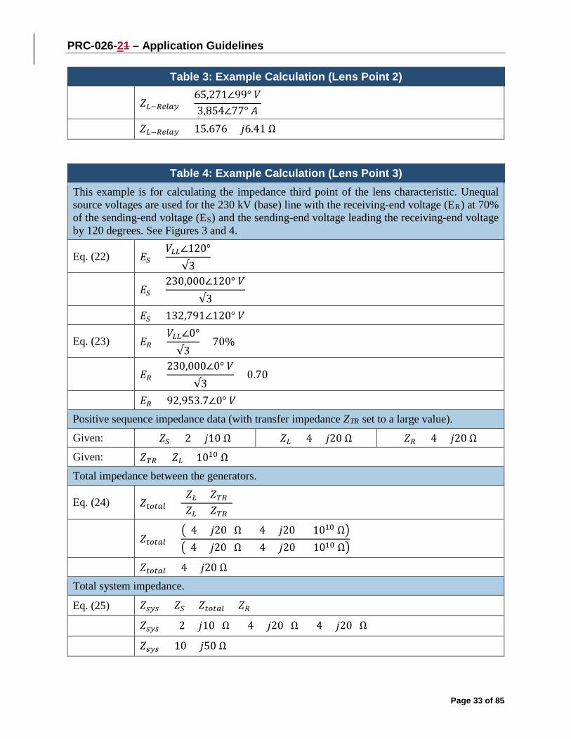
PRC-026-21 – Application Guidelines
Page 33 of 85
Table 3: Example Calculation (Lens Point 2)
𝑍𝑍𝐿𝐿−𝑅𝑅𝑅𝑅𝑡𝑡𝑡𝑡𝑠𝑠 =65,271∠99° 𝑉𝑉3,854∠77° 𝐴𝐴
𝑍𝑍𝐿𝐿−𝑅𝑅𝑅𝑅𝑡𝑡𝑡𝑡𝑠𝑠 = 15.676 + 𝑗𝑗6.41 Ω
Table 4: Example Calculation (Lens Point 3) This example is for calculating the impedance third point of the lens characteristic. Unequal source voltages are used for the 230 kV (base) line with the receiving-end voltage (ER) at 70% of the sending-end voltage (ES) and the sending-end voltage leading the receiving-end voltage by 120 degrees. See Figures 3 and 4.
Eq. (22) 𝐸𝐸𝑆𝑆 =𝑉𝑉𝐿𝐿𝐿𝐿∠120°
√3
𝐸𝐸𝑆𝑆 =
230,000∠120° 𝑉𝑉√3
𝐸𝐸𝑆𝑆 = 132,791∠120° 𝑉𝑉
Eq. (23) 𝐸𝐸𝑅𝑅 =𝑉𝑉𝐿𝐿𝐿𝐿∠0°√3
× 70%
𝐸𝐸𝑅𝑅 =
230,000∠0° 𝑉𝑉√3
× 0.70
𝐸𝐸𝑅𝑅 = 92,953.7∠0° 𝑉𝑉
Positive sequence impedance data (with transfer impedance ZTR set to a large value).
Given: 𝑍𝑍𝑆𝑆 = 2 + 𝑗𝑗10 Ω 𝑍𝑍𝐿𝐿 = 4 + 𝑗𝑗20 Ω 𝑍𝑍𝑅𝑅 = 4 + 𝑗𝑗20 Ω
Given: 𝑍𝑍𝑇𝑇𝑅𝑅 = 𝑍𝑍𝐿𝐿 × 1010 Ω
Total impedance between the generators.
Eq. (24) 𝑍𝑍𝑡𝑡𝑡𝑡𝑡𝑡𝑡𝑡𝑡𝑡 =(𝑍𝑍𝐿𝐿 × 𝑍𝑍𝑇𝑇𝑅𝑅)(𝑍𝑍𝐿𝐿 + 𝑍𝑍𝑇𝑇𝑅𝑅)
𝑍𝑍𝑡𝑡𝑡𝑡𝑡𝑡𝑡𝑡𝑡𝑡 =
�(4 + 𝑗𝑗20) Ω × (4 + 𝑗𝑗20) × 1010 Ω��(4 + 𝑗𝑗20) Ω + (4 + 𝑗𝑗20) × 1010 Ω�
𝑍𝑍𝑡𝑡𝑡𝑡𝑡𝑡𝑡𝑡𝑡𝑡 = 4 + 𝑗𝑗20 Ω Total system impedance.
Eq. (25) 𝑍𝑍𝑠𝑠𝑠𝑠𝑠𝑠 = 𝑍𝑍𝑆𝑆 + 𝑍𝑍𝑡𝑡𝑡𝑡𝑡𝑡𝑡𝑡𝑡𝑡 + 𝑍𝑍𝑅𝑅
𝑍𝑍𝑠𝑠𝑠𝑠𝑠𝑠 = (2 + 𝑗𝑗10) Ω + (4 + 𝑗𝑗20) Ω + (4 + 𝑗𝑗20) Ω
𝑍𝑍𝑠𝑠𝑠𝑠𝑠𝑠 = 10 + 𝑗𝑗50 Ω

PRC-026-21 – Application Guidelines
Page 34 of 85
Table 4: Example Calculation (Lens Point 3) Total system current from sending-end source.
Eq. (26) 𝐼𝐼𝑠𝑠𝑠𝑠𝑠𝑠 =𝐸𝐸𝑆𝑆 − 𝐸𝐸𝑅𝑅𝑍𝑍𝑠𝑠𝑠𝑠𝑠𝑠
𝐼𝐼𝑠𝑠𝑠𝑠𝑠𝑠 =
132,791∠120° 𝑉𝑉 − 92,953.7∠0° 𝑉𝑉(10 + 𝑗𝑗50) Ω
𝐼𝐼𝑠𝑠𝑠𝑠𝑠𝑠 = 3,854∠65.5° 𝐴𝐴
The current, as measured by the relay on ZL (Figure 3), is only the current flowing through that line as determined by using the current divider equation.
Eq. (27) 𝐼𝐼𝐿𝐿 = 𝐼𝐼𝑠𝑠𝑠𝑠𝑠𝑠 ×𝑍𝑍𝑇𝑇𝑅𝑅
𝑍𝑍𝐿𝐿 + 𝑍𝑍𝑇𝑇𝑅𝑅
𝐼𝐼𝐿𝐿 = 3,854∠65.5° 𝐴𝐴 ×
(4 + 𝑗𝑗20) × 1010 Ω(4 + 𝑗𝑗20) Ω + (4 + 𝑗𝑗20) × 1010 Ω
𝐼𝐼𝐿𝐿 = 3,854∠65.5° 𝐴𝐴
The voltage, as measured by the relay on ZL (Figure 3), is the voltage drop from the sending-end source through the sending-end source impedance.
Eq. (28) 𝑉𝑉𝑆𝑆 = 𝐸𝐸𝑆𝑆 − (𝑍𝑍𝑆𝑆 × 𝐼𝐼𝐿𝐿)
𝑉𝑉𝑆𝑆 = 132,791∠120° 𝑉𝑉 − [(2 + 𝑗𝑗10) Ω × 3,854∠65.5° 𝐴𝐴] 𝑉𝑉𝑆𝑆 = 98,265∠110.6° 𝑉𝑉 The impedance seen by the relay on ZL.
Eq. (29) 𝑍𝑍𝐿𝐿−𝑅𝑅𝑅𝑅𝑡𝑡𝑡𝑡𝑠𝑠 =𝑉𝑉𝑆𝑆𝐼𝐼𝐿𝐿
𝑍𝑍𝐿𝐿−𝑅𝑅𝑅𝑅𝑡𝑡𝑡𝑡𝑠𝑠 =
98,265∠110.6° 𝑉𝑉3,854∠65.5° 𝐴𝐴
𝑍𝑍𝐿𝐿−𝑅𝑅𝑅𝑅𝑡𝑡𝑡𝑡𝑠𝑠 = 18.005 + 𝑗𝑗18.054 Ω
Table 5: Example Calculation (Lens Point 4) This example is for calculating the impedance fourth point of the lens characteristic. Equal source voltages are used for the 230 kV (base) line with the sending-end voltage (ES) leading the receiving-end voltage (ER) by 240 degrees. See Figures 3 and 4.
Eq. (30) 𝐸𝐸𝑆𝑆 =𝑉𝑉𝐿𝐿𝐿𝐿∠240°
√3
𝐸𝐸𝑆𝑆 =
230,000∠240° 𝑉𝑉√3

PRC-026-21 – Application Guidelines
Page 35 of 85
Table 5: Example Calculation (Lens Point 4) 𝐸𝐸𝑆𝑆 = 132,791∠240° 𝑉𝑉
Eq. (31) 𝐸𝐸𝑅𝑅 =𝑉𝑉𝐿𝐿𝐿𝐿∠0°√3
𝐸𝐸𝑅𝑅 =
230,000∠0° 𝑉𝑉√3
𝐸𝐸𝑅𝑅 = 132,791∠0° 𝑉𝑉
Positive sequence impedance data (with transfer impedance ZTR set to a large value).
Given: 𝑍𝑍𝑆𝑆 = 2 + 𝑗𝑗10 Ω 𝑍𝑍𝐿𝐿 = 4 + 𝑗𝑗20 Ω 𝑍𝑍𝑅𝑅 = 4 + 𝑗𝑗20 Ω
Given: 𝑍𝑍𝑇𝑇𝑅𝑅 = 𝑍𝑍𝐿𝐿 × 1010 Ω
Total impedance between the generators.
Eq. (32) 𝑍𝑍𝑡𝑡𝑡𝑡𝑡𝑡𝑡𝑡𝑡𝑡 =(𝑍𝑍𝐿𝐿 × 𝑍𝑍𝑇𝑇𝑅𝑅)(𝑍𝑍𝐿𝐿 + 𝑍𝑍𝑇𝑇𝑅𝑅)
𝑍𝑍𝑡𝑡𝑡𝑡𝑡𝑡𝑡𝑡𝑡𝑡 =
�(4 + 𝑗𝑗20) Ω × (4 + 𝑗𝑗20) × 1010 Ω��(4 + 𝑗𝑗20) Ω + (4 + 𝑗𝑗20) × 1010 Ω�
𝑍𝑍𝑡𝑡𝑡𝑡𝑡𝑡𝑡𝑡𝑡𝑡 = 4 + 𝑗𝑗20 Ω
Total system impedance.
Eq. (33) 𝑍𝑍𝑠𝑠𝑠𝑠𝑠𝑠 = 𝑍𝑍𝑆𝑆 + 𝑍𝑍𝑡𝑡𝑡𝑡𝑡𝑡𝑡𝑡𝑡𝑡 + 𝑍𝑍𝑅𝑅
𝑍𝑍𝑠𝑠𝑠𝑠𝑠𝑠 = (2 + 𝑗𝑗10) Ω + (4 + 𝑗𝑗20) Ω + (4 + 𝑗𝑗20) Ω
𝑍𝑍𝑠𝑠𝑠𝑠𝑠𝑠 = 10 + 𝑗𝑗50 Ω
Total system current from sending-end source.
Eq. (34) 𝐼𝐼𝑠𝑠𝑠𝑠𝑠𝑠 =𝐸𝐸𝑆𝑆 − 𝐸𝐸𝑅𝑅𝑍𝑍𝑠𝑠𝑠𝑠𝑠𝑠
𝐼𝐼𝑠𝑠𝑠𝑠𝑠𝑠 =
132,791∠240° 𝑉𝑉 − 132,791∠0° 𝑉𝑉(10 + 𝑗𝑗50 )Ω
𝐼𝐼𝑠𝑠𝑠𝑠𝑠𝑠 = 4,511∠131.3° 𝐴𝐴
The current, as measured by the relay on ZL (Figure 3), is only the current flowing through that line as determined by using the current divider equation.
Eq. (35) 𝐼𝐼𝐿𝐿 = 𝐼𝐼𝑠𝑠𝑠𝑠𝑠𝑠 ×𝑍𝑍𝑇𝑇𝑅𝑅
𝑍𝑍𝐿𝐿 + 𝑍𝑍𝑇𝑇𝑅𝑅
𝐼𝐼𝐿𝐿 = 4,511∠131.1° 𝐴𝐴 ×
(4 + 𝑗𝑗20) × 1010 Ω(4 + 𝑗𝑗20) Ω + (4 + 𝑗𝑗20) × 1010 Ω
𝐼𝐼𝐿𝐿 = 4,511∠131.1° 𝐴𝐴

PRC-026-21 – Application Guidelines
Page 36 of 85
Table 5: Example Calculation (Lens Point 4) The voltage, as measured by the relay on ZL (Figure 3), is the voltage drop from the sending-end source through the sending-end source impedance.
Eq. (36) 𝑉𝑉𝑆𝑆 = 𝐸𝐸𝑆𝑆 − (𝑍𝑍𝑆𝑆 × 𝐼𝐼𝐿𝐿)
𝑉𝑉𝑆𝑆 = 132,791∠240° 𝑉𝑉 − [(2 + 𝑗𝑗10 ) Ω × 4,511∠131.1° 𝐴𝐴] 𝑉𝑉𝑆𝑆 = 95,756∠ − 106.1° 𝑉𝑉
The impedance seen by the relay on ZL.
Eq. (37) 𝑍𝑍𝐿𝐿−𝑅𝑅𝑅𝑅𝑡𝑡𝑡𝑡𝑠𝑠 =𝑉𝑉𝑆𝑆𝐼𝐼𝐿𝐿
𝑍𝑍𝐿𝐿−𝑅𝑅𝑅𝑅𝑡𝑡𝑡𝑡𝑠𝑠 =
95,756∠ − 106.1° 𝑉𝑉4,511∠131.1° 𝐴𝐴
𝑍𝑍𝐿𝐿−𝑅𝑅𝑅𝑅𝑡𝑡𝑡𝑡𝑠𝑠 = −11.434 + 𝑗𝑗17.887 Ω
Table 6: Example Calculation (Lens Point 5) This example is for calculating the impedance fifth point of the lens characteristic. Unequal source voltages are used for the 230 kV (base) line with the sending-end voltage (ES) at 70% of the receiving-end voltage (ER) and leading the receiving-end voltage by 240 degrees. See Figures 3 and 4.
Eq. (38) 𝐸𝐸𝑆𝑆 =𝑉𝑉𝐿𝐿𝐿𝐿∠240°
√3× 70%
𝐸𝐸𝑆𝑆 =230,000∠240° 𝑉𝑉
√3× 0.70
𝐸𝐸𝑆𝑆 = 92,953.7∠240° 𝑉𝑉
Eq. (39) 𝐸𝐸𝑅𝑅 =𝑉𝑉𝐿𝐿𝐿𝐿∠0°√3
𝐸𝐸𝑅𝑅 =230,000∠0° 𝑉𝑉
√3
𝐸𝐸𝑅𝑅 = 132,791∠0° 𝑉𝑉
Positive sequence impedance data (with transfer impedance ZTR set to a large value).
Given: 𝑍𝑍𝑆𝑆 = 2 + 𝑗𝑗10 Ω 𝑍𝑍𝐿𝐿 = 4 + 𝑗𝑗20 Ω 𝑍𝑍𝑅𝑅 = 4 + 𝑗𝑗20 Ω
Given: 𝑍𝑍𝑇𝑇𝑅𝑅 = 𝑍𝑍𝐿𝐿 × 1010 Ω
Total impedance between the generators.
Eq. (40) 𝑍𝑍𝑡𝑡𝑡𝑡𝑡𝑡𝑡𝑡𝑡𝑡 =(𝑍𝑍𝐿𝐿 × 𝑍𝑍𝑇𝑇𝑅𝑅)(𝑍𝑍𝐿𝐿 + 𝑍𝑍𝑇𝑇𝑅𝑅)

PRC-026-21 – Application Guidelines
Page 37 of 85
Table 6: Example Calculation (Lens Point 5)
𝑍𝑍𝑡𝑡𝑡𝑡𝑡𝑡𝑡𝑡𝑡𝑡 =�(4 + 𝑗𝑗20) Ω × (4 + 𝑗𝑗20) × 1010 Ω��(4 + 𝑗𝑗20) Ω + (4 + 𝑗𝑗20) × 1010 Ω�
𝑍𝑍𝑡𝑡𝑡𝑡𝑡𝑡𝑡𝑡𝑡𝑡 = 4 + 𝑗𝑗20 Ω
Total system impedance.
Eq. (41) 𝑍𝑍𝑠𝑠𝑠𝑠𝑠𝑠 = 𝑍𝑍𝑆𝑆 + 𝑍𝑍𝑡𝑡𝑡𝑡𝑡𝑡𝑡𝑡𝑡𝑡 + 𝑍𝑍𝑅𝑅
𝑍𝑍𝑠𝑠𝑠𝑠𝑠𝑠 = (2 + 𝑗𝑗10 Ω) + (4 + 𝑗𝑗20 Ω) + (4 + 𝑗𝑗20 Ω)
𝑍𝑍𝑠𝑠𝑠𝑠𝑠𝑠 = 10 + 𝑗𝑗50 Ω
Total system current from sending-end source.
Eq. (42) 𝐼𝐼𝑠𝑠𝑠𝑠𝑠𝑠 =𝐸𝐸𝑆𝑆 − 𝐸𝐸𝑅𝑅𝑍𝑍𝑠𝑠𝑠𝑠𝑠𝑠
𝐼𝐼𝑠𝑠𝑠𝑠𝑠𝑠 =92,953.7∠240° 𝑉𝑉 − 132,791∠0° 𝑉𝑉
10 + 𝑗𝑗50 Ω
𝐼𝐼𝑠𝑠𝑠𝑠𝑠𝑠 = 3,854∠125.5° 𝐴𝐴
The current, as measured by the relay on ZL (Figure 3), is only the current flowing through that line as determined by using the current divider equation.
Eq. (43) 𝐼𝐼𝐿𝐿 = 𝐼𝐼𝑠𝑠𝑠𝑠𝑠𝑠 ×𝑍𝑍𝑇𝑇𝑅𝑅
𝑍𝑍𝐿𝐿 + 𝑍𝑍𝑇𝑇𝑅𝑅
𝐼𝐼𝐿𝐿 = 3,854∠125.5° 𝐴𝐴 ×(4 + 𝑗𝑗20) × 1010 Ω
(4 + 𝑗𝑗20) Ω + (4 + 𝑗𝑗20) × 1010 Ω
𝐼𝐼𝐿𝐿 = 3,854∠125.5° 𝐴𝐴
The voltage, as measured by the relay on ZL (Figure 3), is the voltage drop from the sending-end source through the sending-end source impedance.
Eq. (44) 𝑉𝑉𝑆𝑆 = 𝐸𝐸𝑆𝑆 − (𝑍𝑍𝑆𝑆 × 𝐼𝐼𝐿𝐿)
𝑉𝑉𝑆𝑆 = 92,953.7∠240° 𝑉𝑉 − [(2 + 𝑗𝑗10 ) Ω × 3,854∠125.5° 𝐴𝐴] 𝑉𝑉𝑆𝑆 = 65,270.5∠ − 99.4° 𝑉𝑉
The impedance seen by the relay on ZL.
Eq. (45) 𝑍𝑍𝐿𝐿−𝑅𝑅𝑅𝑅𝑡𝑡𝑡𝑡𝑠𝑠 =𝑉𝑉𝑆𝑆𝐼𝐼𝐿𝐿
𝑍𝑍𝐿𝐿−𝑅𝑅𝑅𝑅𝑡𝑡𝑡𝑡𝑠𝑠 =65,270.5∠ − 99.4° 𝑉𝑉
3,854∠125.5° 𝐴𝐴
𝑍𝑍𝐿𝐿−𝑅𝑅𝑅𝑅𝑡𝑡𝑡𝑡𝑠𝑠 = −12.005 + 𝑗𝑗11.946 Ω

PRC-026-21 – Application Guidelines
Page 38 of 85
Table 7: Example Calculation (Lens Point 6) This example is for calculating the impedance sixth point of the lens characteristic. Unequal source voltages are used for the 230 kV (base) line with the receiving-end voltage (ER) at 70% of the sending-end voltage (ES) and the sending-end voltage leading the receiving-end voltage by 240 degrees. See Figures 3 and 4.
Eq. (46) 𝐸𝐸𝑆𝑆 =𝑉𝑉𝐿𝐿𝐿𝐿∠240°
√3
𝐸𝐸𝑆𝑆 =230,000∠240° 𝑉𝑉
√3
𝐸𝐸𝑆𝑆 = 132,791∠240° 𝑉𝑉
Eq. (47) 𝐸𝐸𝑅𝑅 =𝑉𝑉𝐿𝐿𝐿𝐿∠0°√3
× 70%
𝐸𝐸𝑅𝑅 =230,000∠0° 𝑉𝑉
√3× 0.70
𝐸𝐸𝑅𝑅 = 92,953.7∠0° 𝑉𝑉 Positive sequence impedance data (with transfer impedance ZTR set to a large value). Given: 𝑍𝑍𝑆𝑆 = 2 + 𝑗𝑗10 Ω 𝑍𝑍𝐿𝐿 = 4 + 𝑗𝑗20 Ω 𝑍𝑍𝑅𝑅 = 4 + 𝑗𝑗20 Ω Given: 𝑍𝑍𝑇𝑇𝑅𝑅 = 𝑍𝑍𝐿𝐿 × 1010 Ω Total impedance between the generators.
Eq. (48) 𝑍𝑍𝑡𝑡𝑡𝑡𝑡𝑡𝑡𝑡𝑡𝑡 =(𝑍𝑍𝐿𝐿 × 𝑍𝑍𝑇𝑇𝑅𝑅)(𝑍𝑍𝐿𝐿 + 𝑍𝑍𝑇𝑇𝑅𝑅)
𝑍𝑍𝑡𝑡𝑡𝑡𝑡𝑡𝑡𝑡𝑡𝑡 =�(4 + 𝑗𝑗20) Ω × (4 + 𝑗𝑗20) × 1010 Ω��(4 + 𝑗𝑗20) Ω + (4 + 𝑗𝑗20) × 1010 Ω�
𝑍𝑍𝑡𝑡𝑡𝑡𝑡𝑡𝑡𝑡𝑡𝑡 = 4 + 𝑗𝑗20 Ω Total system impedance. Eq. (49) 𝑍𝑍𝑠𝑠𝑠𝑠𝑠𝑠 = 𝑍𝑍𝑆𝑆 + 𝑍𝑍𝑡𝑡𝑡𝑡𝑡𝑡𝑡𝑡𝑡𝑡 + 𝑍𝑍𝑅𝑅 𝑍𝑍𝑠𝑠𝑠𝑠𝑠𝑠 = (2 + 𝑗𝑗10) Ω + (4 + 𝑗𝑗20) Ω + (4 + 𝑗𝑗20) Ω 𝑍𝑍𝑠𝑠𝑠𝑠𝑠𝑠 = 10 + 𝑗𝑗50 Ω Total system current from sending-end source.
Eq. (50) 𝐼𝐼𝑠𝑠𝑠𝑠𝑠𝑠 =𝐸𝐸𝑆𝑆 − 𝐸𝐸𝑅𝑅𝑍𝑍𝑠𝑠𝑠𝑠𝑠𝑠
𝐼𝐼𝑠𝑠𝑠𝑠𝑠𝑠 =132,791∠240° 𝑉𝑉 − 92,953.7∠0° 𝑉𝑉
10 + 𝑗𝑗50 Ω
𝐼𝐼𝑠𝑠𝑠𝑠𝑠𝑠 = 3,854∠137.1° 𝐴𝐴

PRC-026-21 – Application Guidelines
Page 39 of 85
Table 7: Example Calculation (Lens Point 6) The current, as measured by the relay on ZL (Figure 3), is only the current flowing through that line as determined by using the current divider equation.
Eq. (51) 𝐼𝐼𝐿𝐿 = 𝐼𝐼𝑠𝑠𝑠𝑠𝑠𝑠 ×𝑍𝑍𝑇𝑇𝑅𝑅
𝑍𝑍𝐿𝐿 + 𝑍𝑍𝑇𝑇𝑅𝑅
𝐼𝐼𝐿𝐿 = 3,854∠137.1° 𝐴𝐴 ×(4 + 𝑗𝑗20) × 1010 Ω
(4 + 𝑗𝑗20) Ω + (4 + 𝑗𝑗20) × 1010 Ω
𝐼𝐼𝐿𝐿 = 3,854∠137.1° 𝐴𝐴 The voltage, as measured by the relay on ZL (Figure 3), is the voltage drop from the sending-end source through the sending-end source impedance. Eq. (52) 𝑉𝑉𝑆𝑆 = 𝐸𝐸𝑆𝑆 − (𝑍𝑍𝑆𝑆 × 𝐼𝐼𝐿𝐿) 𝑉𝑉𝑆𝑆 = 132,791∠240° 𝑉𝑉 − [(2 + 𝑗𝑗10 ) Ω × 3,854∠137.1° 𝐴𝐴] 𝑉𝑉𝑆𝑆 = 98,265∠ − 110.6° 𝑉𝑉 The impedance seen by the relay on ZL.
Eq. (53) 𝑍𝑍𝐿𝐿−𝑅𝑅𝑅𝑅𝑡𝑡𝑡𝑡𝑠𝑠 =𝑉𝑉𝑆𝑆𝐼𝐼𝐿𝐿
𝑍𝑍𝐿𝐿−𝑅𝑅𝑅𝑅𝑡𝑡𝑡𝑡𝑠𝑠 =98,265∠ − 110.6° 𝑉𝑉
3,854∠137.1° 𝐴𝐴
𝑍𝑍𝐿𝐿−𝑅𝑅𝑅𝑅𝑡𝑡𝑡𝑡𝑠𝑠 = −9.676 + 𝑗𝑗23.59 Ω
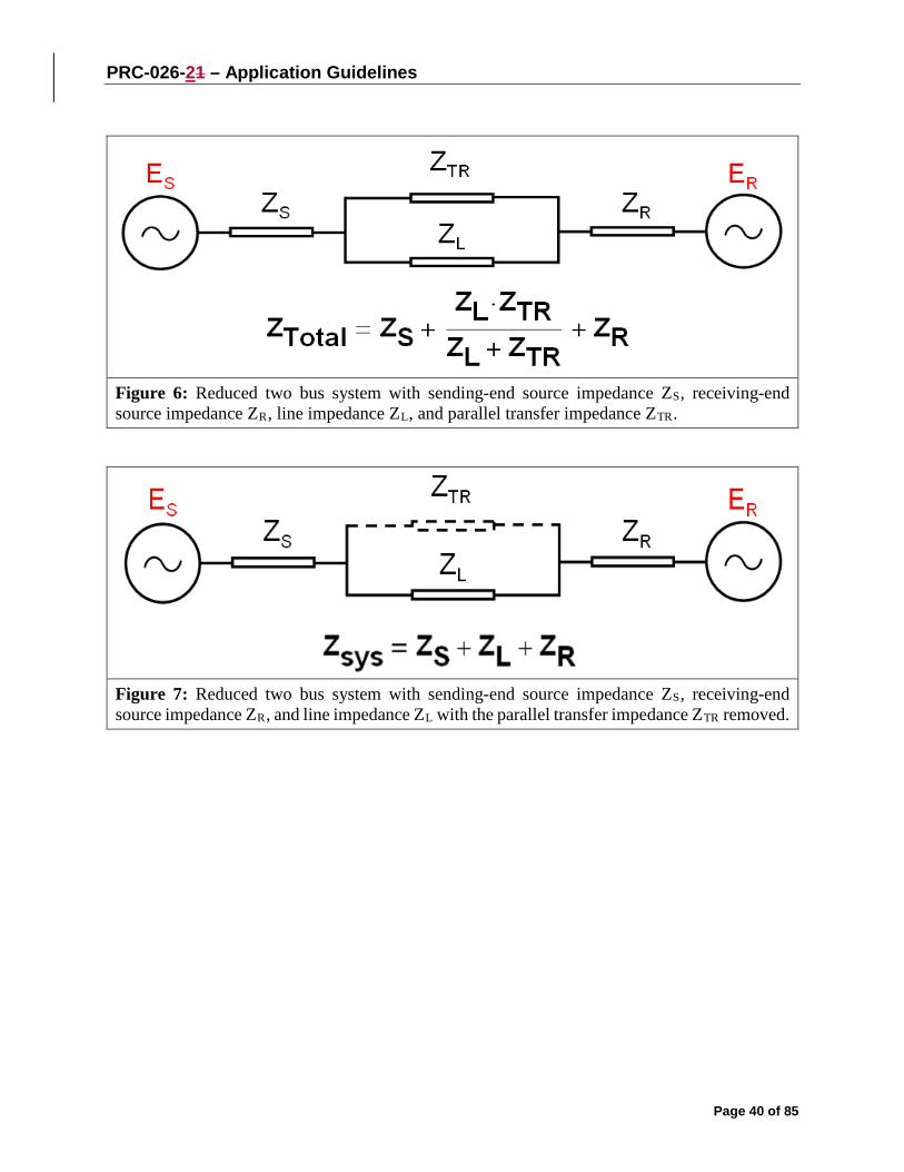
PRC-026-21 – Application Guidelines
Page 40 of 85
Figure 6: Reduced two bus system with sending-end source impedance ZS, receiving-end source impedance ZR, line impedance ZL, and parallel transfer impedance ZTR.
Figure 7: Reduced two bus system with sending-end source impedance ZS, receiving-end source impedance ZR, and line impedance ZL with the parallel transfer impedance ZTR removed.

PRC-026-21 – Application Guidelines
Page 41 of 85
Figure 8: A strong-source system with a line impedance of ZL = 20.4 ohms (i.e., the thicker red line). This mho element characteristic (i.e., the blue circle) does not meet the PRC-026-1 – Attachment B, Criterion A because it is not completely contained within the unstable power swing region (i.e., the orange characteristic).
Figure 8 above represents a heavily-loaded system with all generation in service and all transmission BES Elements in their normal operating state. The mho element characteristic (set at 137% of ZL) extends into the unstable power swing region (i.e., the orange characteristic). Using the strongest source system is more conservative because it shrinks the unstable power swing region, bringing it closer to the mho element characteristic. This figure also graphically represents the effect of a system strengthening over time and this is the reason for re-evaluation if the relay has not been evaluated in the last five calendar years. Figure 9 below depicts a relay that meets the PRC-026-1 – Attachment B, Criterion A. Figure 8 depicts the same relay with the same setting five years later, where each source has strengthened by about 10% and now the same mho element characteristic does not meet Criterion A.

PRC-026-21 – Application Guidelines
Page 42 of 85
Figure 9: A weak-source system with a line impedance of ZL = 20.4 ohms (i.e., the thicker red line). This mho element characteristic (i.e., the blue circle) meets the PRC-026-1 – Attachment B, Criterion A because it is completely contained within the unstable power swing region (i.e., the orange characteristic).
Figure 9 above represents a lightly-loaded system, using a minimum generation profile. The mho element characteristic (set at 137% of ZL) does not extend into the unstable power swing region (i.e., the orange characteristic). Using a weaker source system expands the unstable power swing region away from the mho element characteristic.

PRC-026-21 – Application Guidelines
Page 43 of 85
Figure 10: This is an example of an unstable power swing region (i.e., the orange characteristic) with the parallel transfer impedance removed. This relay mho element characteristic (i.e., the blue circle) does not meet PRC-026-1 – Attachment B, Criterion A because it is not completely contained within the unstable power swing region.
Table 8: Example Calculation (Parallel Transfer Impedance Removed) Calculations for the point at 120 degrees with equal source impedances. The total system current equals the line current. See Figure 10.
Eq. (54) 𝐸𝐸𝑆𝑆 =𝑉𝑉𝐿𝐿𝐿𝐿∠120°
√3
𝐸𝐸𝑆𝑆 =
230,000∠120° 𝑉𝑉√3
𝐸𝐸𝑆𝑆 = 132,791∠120° 𝑉𝑉

PRC-026-21 – Application Guidelines
Page 44 of 85
Table 8: Example Calculation (Parallel Transfer Impedance Removed)
Eq. (55) 𝐸𝐸𝑅𝑅 =𝑉𝑉𝐿𝐿𝐿𝐿∠0°√3
𝐸𝐸𝑅𝑅 =
230,000∠0° 𝑉𝑉√3
𝐸𝐸𝑅𝑅 = 132,791∠0° 𝑉𝑉 Given impedance data.
Given: 𝑍𝑍𝑆𝑆 = 2 + 𝑗𝑗10 Ω 𝑍𝑍𝐿𝐿 = 4 + 𝑗𝑗20 Ω 𝑍𝑍𝑅𝑅 = 4 + 𝑗𝑗20 Ω
Given: 𝑍𝑍𝑇𝑇𝑅𝑅 = 𝑍𝑍𝐿𝐿 × 1010 Ω Total impedance between the generators.
Eq. (56) 𝑍𝑍𝑡𝑡𝑡𝑡𝑡𝑡𝑡𝑡𝑡𝑡 =(𝑍𝑍𝐿𝐿 × 𝑍𝑍𝑇𝑇𝑅𝑅)(𝑍𝑍𝐿𝐿 + 𝑍𝑍𝑇𝑇𝑅𝑅)
𝑍𝑍𝑡𝑡𝑡𝑡𝑡𝑡𝑡𝑡𝑡𝑡 =
�(4 + 𝑗𝑗20) Ω × (4 + 𝑗𝑗20) × 1010 Ω��(4 + 𝑗𝑗20) Ω + (4 + 𝑗𝑗20) × 1010 Ω�
𝑍𝑍𝑡𝑡𝑡𝑡𝑡𝑡𝑡𝑡𝑡𝑡 = 4 + 𝑗𝑗20 Ω
Total system impedance.
Eq. (57) 𝑍𝑍𝑠𝑠𝑠𝑠𝑠𝑠 = 𝑍𝑍𝑆𝑆 + 𝑍𝑍𝑡𝑡𝑡𝑡𝑡𝑡𝑡𝑡𝑡𝑡 + 𝑍𝑍𝑅𝑅
𝑍𝑍𝑠𝑠𝑠𝑠𝑠𝑠 = (2 + 𝑗𝑗10) Ω + (4 + 𝑗𝑗20) Ω + (4 + 𝑗𝑗20) Ω
𝑍𝑍𝑠𝑠𝑠𝑠𝑠𝑠 = 10 + 𝑗𝑗50 Ω
Total system current from sending-end source.
Eq. (58) 𝐼𝐼𝑠𝑠𝑠𝑠𝑠𝑠 =𝐸𝐸𝑆𝑆 − 𝐸𝐸𝑅𝑅𝑍𝑍𝑠𝑠𝑠𝑠𝑠𝑠
𝐼𝐼𝑠𝑠𝑠𝑠𝑠𝑠 =
132,791∠120° 𝑉𝑉 − 132,791∠0° 𝑉𝑉10 + 𝑗𝑗50 Ω
𝐼𝐼𝑠𝑠𝑠𝑠𝑠𝑠 = 4,511∠71.3° 𝐴𝐴
The current, as measured by the relay on ZL (Figure 3), is only the current flowing through that line as determined by using the current divider equation.
Eq. (59) 𝐼𝐼𝐿𝐿 = 𝐼𝐼𝑠𝑠𝑠𝑠𝑠𝑠 ×𝑍𝑍𝑇𝑇𝑅𝑅
𝑍𝑍𝐿𝐿 + 𝑍𝑍𝑇𝑇𝑅𝑅
𝐼𝐼𝐿𝐿 = 4,511∠71.3° 𝐴𝐴 ×
(4 + 𝑗𝑗20) × 1010 Ω(4 + 𝑗𝑗20) Ω + (4 + 𝑗𝑗20) × 1010 Ω
𝐼𝐼𝐿𝐿 = 4,511∠71.3° 𝐴𝐴

PRC-026-21 – Application Guidelines
Page 45 of 85
Table 8: Example Calculation (Parallel Transfer Impedance Removed) The voltage, as measured by the relay on ZL (Figure 3), is the voltage drop from the sending-end source through the sending-end source impedance.
Eq. (60) 𝑉𝑉𝑆𝑆 = 𝐸𝐸𝑆𝑆 − �𝑍𝑍𝑆𝑆 × 𝐼𝐼𝑠𝑠𝑠𝑠𝑠𝑠�
𝑉𝑉𝑆𝑆 = 132,791∠120° 𝑉𝑉 − [(2 + 𝑗𝑗10 Ω) × 4,511∠71.3° 𝐴𝐴] 𝑉𝑉𝑆𝑆 = 95,757∠106.1° 𝑉𝑉
The impedance seen by the relay on ZL.
Eq. (61) 𝑍𝑍𝐿𝐿−𝑅𝑅𝑅𝑅𝑡𝑡𝑡𝑡𝑠𝑠 =𝑉𝑉𝑆𝑆𝐼𝐼𝐿𝐿
𝑍𝑍𝐿𝐿−𝑅𝑅𝑅𝑅𝑡𝑡𝑡𝑡𝑠𝑠 =
95,757∠106.1° 𝑉𝑉4,511∠71.3° 𝐴𝐴
𝑍𝑍𝐿𝐿−𝑅𝑅𝑅𝑅𝑡𝑡𝑡𝑡𝑠𝑠 = 17.434 + 𝑗𝑗12.113 Ω

PRC-026-21 – Application Guidelines
Page 46 of 85
Figure 11: This is an example of an unstable power swing region (i.e., the orange characteristic) with the parallel transfer impedance included causing the mho element characteristic (i.e., the blue circle) to appear to meet the PRC-026-1 – Attachment B, Criterion A because it is completely contained within the unstable power swing region. Including the parallel transfer impedance in the calculation is not allowed by the PRC-026-1 – Attachment B, Criterion A.
In Figure 11 above, the parallel transfer impedance is 5 times the line impedance. The unstable power swing region has expanded out beyond the mho element characteristic due to the infeed effect from the parallel current through the parallel transfer impedance, thus allowing the mho element characteristic to appear to meet the PRC-026-1 – Attachment B, Criterion A. Including the parallel transfer impedance in the calculation is not allowed by the PRC-026-1 – Attachment B, Criterion A.

PRC-026-21 – Application Guidelines
Page 47 of 85
Table 9: Example Calculation (Parallel Transfer Impedance Included) Calculations for the point at 120 degrees with equal source impedances. The total system current does not equal the line current. See Figure 11.
Eq. (62) 𝐸𝐸𝑆𝑆 =𝑉𝑉𝐿𝐿𝐿𝐿∠120°
√3
𝐸𝐸𝑆𝑆 =
230,000∠120° 𝑉𝑉√3
𝐸𝐸𝑆𝑆 = 132,791∠120° 𝑉𝑉
Eq. (63) 𝐸𝐸𝑅𝑅 =𝑉𝑉𝐿𝐿𝐿𝐿∠0°√3
𝐸𝐸𝑅𝑅 =
230,000∠0° 𝑉𝑉√3
𝐸𝐸𝑅𝑅 = 132,791∠0° 𝑉𝑉 Given impedance data.
Given: 𝑍𝑍𝑆𝑆 = 2 + 𝑗𝑗10 Ω 𝑍𝑍𝐿𝐿 = 4 + 𝑗𝑗20 Ω 𝑍𝑍𝑅𝑅 = 4 + 𝑗𝑗20 Ω
Given: 𝑍𝑍𝑇𝑇𝑅𝑅 = 𝑍𝑍𝐿𝐿 × 5
𝑍𝑍𝑇𝑇𝑅𝑅 = (4 + 𝑗𝑗20) Ω × 5
𝑍𝑍𝑇𝑇𝑅𝑅 = 20 + 𝑗𝑗100 Ω
Total impedance between the generators.
Eq. (64) 𝑍𝑍𝑡𝑡𝑡𝑡𝑡𝑡𝑡𝑡𝑡𝑡 =(𝑍𝑍𝐿𝐿 × 𝑍𝑍𝑇𝑇𝑅𝑅)(𝑍𝑍𝐿𝐿 + 𝑍𝑍𝑇𝑇𝑅𝑅)
𝑍𝑍𝑡𝑡𝑡𝑡𝑡𝑡𝑡𝑡𝑡𝑡 =
(4 + 𝑗𝑗20) Ω × (20 + 𝑗𝑗100) Ω(4 + 𝑗𝑗20) Ω + (20 + 𝑗𝑗100) Ω
𝑍𝑍𝑡𝑡𝑡𝑡𝑡𝑡𝑡𝑡𝑡𝑡 = 3.333 + 𝑗𝑗16.667 Ω Total system impedance.
Eq. (65) 𝑍𝑍𝑠𝑠𝑠𝑠𝑠𝑠 = 𝑍𝑍𝑆𝑆 + 𝑍𝑍𝑡𝑡𝑡𝑡𝑡𝑡𝑡𝑡𝑡𝑡 + 𝑍𝑍𝑅𝑅
𝑍𝑍𝑠𝑠𝑠𝑠𝑠𝑠 = (2 + 𝑗𝑗10) Ω + (3.333 + 𝑗𝑗16.667) Ω + (4 + 𝑗𝑗20) Ω
𝑍𝑍𝑠𝑠𝑠𝑠𝑠𝑠 = 9.333 + 𝑗𝑗46.667 Ω
Total system current from sending-end source.
Eq. (66) 𝐼𝐼𝑠𝑠𝑠𝑠𝑠𝑠 =𝐸𝐸𝑆𝑆 − 𝐸𝐸𝑅𝑅𝑍𝑍𝑠𝑠𝑠𝑠𝑠𝑠
𝐼𝐼𝑠𝑠𝑠𝑠𝑠𝑠 =
132,791∠120° 𝑉𝑉 − 132,791∠0° 𝑉𝑉9.333 + 𝑗𝑗46.667 Ω

PRC-026-21 – Application Guidelines
Page 48 of 85
Table 9: Example Calculation (Parallel Transfer Impedance Included) 𝐼𝐼𝑠𝑠𝑠𝑠𝑠𝑠 = 4,833∠71.3° 𝐴𝐴
The current, as measured by the relay on ZL (Figure 3), is only the current flowing through that line as determined by using the current divider equation.
Eq. (67) 𝐼𝐼𝐿𝐿 = 𝐼𝐼𝑠𝑠𝑠𝑠𝑠𝑠 ×𝑍𝑍𝑇𝑇𝑅𝑅
𝑍𝑍𝐿𝐿 + 𝑍𝑍𝑇𝑇𝑅𝑅
𝐼𝐼𝐿𝐿 = 4,833∠71.3° 𝐴𝐴 ×
(20 + 𝑗𝑗100) Ω(4 + 𝑗𝑗20) Ω + (20 + 𝑗𝑗100) Ω
𝐼𝐼𝐿𝐿 = 4,027.4∠71.3° 𝐴𝐴
The voltage, as measured by the relay on ZL (Figure 3), is the voltage drop from the sending-end source through the sending-end source impedance.
Eq. (68) 𝑉𝑉𝑆𝑆 = 𝐸𝐸𝑆𝑆 − �𝑍𝑍𝑆𝑆 × 𝐼𝐼𝑠𝑠𝑠𝑠𝑠𝑠�
𝑉𝑉𝑆𝑆 = 132,791∠120° 𝑉𝑉 − [(2 + 𝑗𝑗10 Ω) × 4,833∠71.3° 𝐴𝐴] 𝑉𝑉𝑆𝑆 = 93,417∠104.7° 𝑉𝑉
The impedance seen by the relay on ZL.
Eq. (69) 𝑍𝑍𝐿𝐿−𝑅𝑅𝑅𝑅𝑡𝑡𝑡𝑡𝑠𝑠 =𝑉𝑉𝑆𝑆𝐼𝐼𝐿𝐿
𝑍𝑍𝐿𝐿−𝑅𝑅𝑅𝑅𝑡𝑡𝑡𝑡𝑠𝑠 =
93,417∠104.7° 𝑉𝑉4,027∠71.3° 𝐴𝐴
𝑍𝑍𝐿𝐿−𝑅𝑅𝑅𝑅𝑡𝑡𝑡𝑡𝑠𝑠 = 19.366 + 𝑗𝑗12.767 Ω

PRC-026-21 – Application Guidelines
Page 49 of 85
Table 10: Percent Increase of a Lens Due To Parallel Transfer Impedance. The following demonstrates the percent size increase of the lens characteristic for ZTR in multiples of ZL with the parallel transfer impedance included.
ZTR in multiples of ZL Percent increase of lens with equal EMF sources (Infinite source as reference)
Infinite N/A
1000 0.05%
100 0.46%
10 4.63%
5 9.27%
2 23.26%
1 46.76%
0.5 94.14%
0.25 189.56%

PRC-026-21 – Application Guidelines
Page 50 of 85
Figure 12: The tripping portion of the mho element characteristic (i.e., the blue circle) not blocked by load encroachment (i.e., the parallel green lines) is completely contained within the unstable power swing region (i.e., the orange characteristic). Therefore, the mho element characteristic meets the PRC-026-1 – Attachment B, Criterion A.

PRC-026-21 – Application Guidelines
Page 51 of 85
Figure 13: The infeed diagram shows the impedance in front of the relay R with the parallel transfer impedance included. As the parallel transfer impedance approaches infinity, the impedances seen by the relay R in the forward direction becomes ZL + ZR.
Table 11: Calculations (System Apparent Impedance in the forward direction) The following equations are provided for calculating the apparent impedance back to the ER source voltage as seen by relay R. Infeed equations from VS to source ER where ER = 0. See Figure 13.
Eq. (70) 𝐼𝐼𝐿𝐿 =𝑉𝑉𝑆𝑆 − 𝑉𝑉𝑅𝑅𝑍𝑍𝐿𝐿
Eq. (71) 𝐼𝐼𝑠𝑠𝑠𝑠𝑠𝑠 =𝑉𝑉𝑅𝑅 − 𝐸𝐸𝑅𝑅𝑍𝑍𝑅𝑅
Eq. (72) 𝐼𝐼𝑠𝑠𝑠𝑠𝑠𝑠 = 𝐼𝐼𝐿𝐿 + 𝐼𝐼𝑇𝑇𝑅𝑅
Eq. (73) 𝐼𝐼𝑠𝑠𝑠𝑠𝑠𝑠 =𝑉𝑉𝑅𝑅𝑍𝑍𝑅𝑅
Since 𝐸𝐸𝑅𝑅 = 0 Rearranged: 𝑉𝑉𝑅𝑅 = 𝐼𝐼𝑠𝑠𝑠𝑠𝑠𝑠 × 𝑍𝑍𝑅𝑅
Eq. (74) 𝐼𝐼𝐿𝐿 =𝑉𝑉𝑆𝑆 − 𝐼𝐼𝑠𝑠𝑠𝑠𝑠𝑠 × 𝑍𝑍𝑅𝑅
𝑍𝑍𝐿𝐿
Eq. (75) 𝐼𝐼𝐿𝐿 =𝑉𝑉𝑆𝑆 − [(𝐼𝐼𝐿𝐿 + 𝐼𝐼𝑇𝑇𝑅𝑅) × 𝑍𝑍𝑅𝑅]
𝑍𝑍𝐿𝐿
Eq. (76) 𝑉𝑉𝑆𝑆 = (𝐼𝐼𝐿𝐿 × 𝑍𝑍𝐿𝐿) + (𝐼𝐼𝐿𝐿 × 𝑍𝑍𝑅𝑅) + (𝐼𝐼𝑇𝑇𝑅𝑅 × 𝑍𝑍𝑅𝑅)
Eq. (77) 𝑍𝑍𝑅𝑅𝑅𝑅𝑡𝑡𝑡𝑡𝑠𝑠 =𝑉𝑉𝑆𝑆𝐼𝐼𝐿𝐿
= 𝑍𝑍𝐿𝐿 + 𝑍𝑍𝑅𝑅 +𝐼𝐼𝑇𝑇𝑅𝑅 × 𝑍𝑍𝑅𝑅
𝐼𝐼𝐿𝐿= 𝑍𝑍𝐿𝐿 + 𝑍𝑍𝑅𝑅 × �1 +
𝐼𝐼𝑇𝑇𝑅𝑅𝐼𝐼𝐿𝐿�
Eq. (78) 𝐼𝐼𝑇𝑇𝑅𝑅 = 𝐼𝐼𝑠𝑠𝑠𝑠𝑠𝑠 ×𝑍𝑍𝐿𝐿
𝑍𝑍𝐿𝐿 + 𝑍𝑍𝑇𝑇𝑅𝑅
Eq. (79) 𝐼𝐼𝐿𝐿 = 𝐼𝐼𝑠𝑠𝑠𝑠𝑠𝑠 ×𝑍𝑍𝑇𝑇𝑅𝑅
𝑍𝑍𝐿𝐿 + 𝑍𝑍𝑇𝑇𝑅𝑅

PRC-026-21 – Application Guidelines
Page 52 of 85
Table 11: Calculations (System Apparent Impedance in the forward direction)
Eq. (80) 𝐼𝐼𝑇𝑇𝑅𝑅𝐼𝐼𝐿𝐿
=𝑍𝑍𝐿𝐿𝑍𝑍𝑇𝑇𝑅𝑅
The infeed equations shows the impedance in front of the relay R (Figure 13) with the parallel transfer impedance included. As the parallel transfer impedance approaches infinity, the impedances seen by the relay R in the forward direction becomes ZL + ZR.
Eq. (81) 𝑍𝑍𝑅𝑅𝑅𝑅𝑡𝑡𝑡𝑡𝑠𝑠 = 𝑍𝑍𝐿𝐿 + 𝑍𝑍𝑅𝑅 × �1 +𝑍𝑍𝐿𝐿𝑍𝑍𝑇𝑇𝑅𝑅
�
Figure 14: The infeed diagram shows the impedance behind relay R with the parallel transfer impedance included. As the parallel transfer impedance approaches infinity, the impedances seen by the relay R in the reverse direction becomes ZS.
Table 12: Calculations (System Apparent Impedance in the Reverse Direction) The following equations are provided for calculating the apparent impedance back to the ES source voltage as seen by relay R. Infeed equations from VR back to source ES where ES = 0. See Figure 14.
Eq. (82) 𝐼𝐼𝐿𝐿 =𝑉𝑉𝑅𝑅 − 𝑉𝑉𝑆𝑆𝑍𝑍𝐿𝐿
Eq. (83) 𝐼𝐼𝑠𝑠𝑠𝑠𝑠𝑠 =𝑉𝑉𝑆𝑆 − 𝐸𝐸𝑆𝑆𝑍𝑍𝑆𝑆
Eq. (84) 𝐼𝐼𝑠𝑠𝑠𝑠𝑠𝑠 = 𝐼𝐼𝐿𝐿 + 𝐼𝐼𝑇𝑇𝑅𝑅
Eq. (85) 𝐼𝐼𝑠𝑠𝑠𝑠𝑠𝑠 =𝑉𝑉𝑆𝑆𝑍𝑍𝑆𝑆
Since 𝐸𝐸𝑠𝑠 = 0 Rearranged: 𝑉𝑉𝑆𝑆 = 𝐼𝐼𝑠𝑠𝑠𝑠𝑠𝑠 × 𝑍𝑍𝑆𝑆
Eq. (86) 𝐼𝐼𝐿𝐿 =𝑉𝑉𝑅𝑅 − 𝐼𝐼𝑠𝑠𝑠𝑠𝑠𝑠 × 𝑍𝑍𝑆𝑆
𝑍𝑍𝐿𝐿

PRC-026-21 – Application Guidelines
Page 53 of 85
Table 12: Calculations (System Apparent Impedance in the Reverse Direction)
Eq. (87) 𝐼𝐼𝐿𝐿 =𝑉𝑉𝑅𝑅 − [(𝐼𝐼𝐿𝐿 + 𝐼𝐼𝑇𝑇𝑅𝑅) × 𝑍𝑍𝑆𝑆]
𝑍𝑍𝐿𝐿
Eq. (88) 𝑉𝑉𝑅𝑅 = (𝐼𝐼𝐿𝐿 × 𝑍𝑍𝐿𝐿) + (𝐼𝐼𝐿𝐿 × 𝑍𝑍𝑆𝑆) + (𝐼𝐼𝑇𝑇𝑅𝑅 × 𝑍𝑍𝑅𝑅𝑆𝑆)
Eq. (89) 𝑍𝑍𝑅𝑅𝑅𝑅𝑡𝑡𝑡𝑡𝑠𝑠 =𝑉𝑉𝑅𝑅𝐼𝐼𝐿𝐿
= 𝑍𝑍𝐿𝐿 + 𝑍𝑍𝑆𝑆 +𝐼𝐼𝑇𝑇𝑅𝑅 × 𝑍𝑍𝑆𝑆
𝐼𝐼𝐿𝐿= 𝑍𝑍𝐿𝐿 + 𝑍𝑍𝑆𝑆 × �1 +
𝐼𝐼𝑇𝑇𝑅𝑅𝐼𝐼𝐿𝐿�
Eq. (90) 𝐼𝐼𝑇𝑇𝑅𝑅 = 𝐼𝐼𝑠𝑠𝑠𝑠𝑠𝑠 ×𝑍𝑍𝐿𝐿
𝑍𝑍𝐿𝐿 + 𝑍𝑍𝑇𝑇𝑅𝑅
Eq. (91) 𝐼𝐼𝐿𝐿 = 𝐼𝐼𝑠𝑠𝑠𝑠𝑠𝑠 ×𝑍𝑍𝑇𝑇𝑅𝑅
𝑍𝑍𝐿𝐿 + 𝑍𝑍𝑇𝑇𝑅𝑅
Eq. (92) 𝐼𝐼𝑇𝑇𝑅𝑅𝐼𝐼𝐿𝐿
=𝑍𝑍𝐿𝐿𝑍𝑍𝑇𝑇𝑅𝑅
The infeed equations shows the impedance behind relay R (Figure 14) with the parallel transfer impedance included. As the parallel transfer impedance approaches infinity, the impedances seen by the relay R in the reverse direction becomes ZS.
Eq. (93) 𝑍𝑍𝑅𝑅𝑅𝑅𝑡𝑡𝑡𝑡𝑠𝑠 = 𝑍𝑍𝐿𝐿 + 𝑍𝑍𝑆𝑆 × �1 +𝑍𝑍𝐿𝐿𝑍𝑍𝑇𝑇𝑅𝑅
� As seen by relay R at the receiving-end of the line.
Eq. (94) 𝑍𝑍𝑅𝑅𝑅𝑅𝑡𝑡𝑡𝑡𝑠𝑠 = 𝑍𝑍𝑆𝑆 × �1 +𝑍𝑍𝐿𝐿𝑍𝑍𝑇𝑇𝑅𝑅
� Subtract ZL for relay R impedance as seen at sending-end of the line.

PRC-026-21 – Application Guidelines
Page 54 of 85
Figure 15: Out-of-step trip (OST) inner blinder (i.e., the parallel green lines) meets the PRC-026-1 – Attachment B, Criterion A because the inner OST blinder initiates tripping either On-The-Way-In or On-The-Way-Out. Since the inner blinder is completely contained within the unstable power swing region (i.e., the orange characteristic), it meets the PRC-026-1 – Attachment B, Criterion A.

PRC-026-21 – Application Guidelines
Page 55 of 85
Table 13: Example Calculation (Voltage Ratios) These calculations are based on the loss-of-synchronism characteristics for the cases of N < 1 and N > 1 as found in the Application of Out-of-Step Blocking and Tripping Relays, GER-3180, p. 12, Figure 3.18 The GE illustration shows the formulae used to calculate the radius and center of the circles that make up the ends of the portion of the lens.
Voltage ratio equations, source impedance equation with infeed formulae applied, and circle equations.
Given: 𝐸𝐸𝑆𝑆 = 0.7 𝐸𝐸𝑅𝑅 = 1.0
Eq. (95) 𝑁𝑁 =|𝐸𝐸𝑆𝑆||𝐸𝐸𝑅𝑅| =
0.71.0
= 0.7
The total system impedance as seen by the relay with infeed formulae applied.
Given: 𝑍𝑍𝑆𝑆 = 2 + 𝑗𝑗10 Ω 𝑍𝑍𝐿𝐿 = 4 + 𝑗𝑗20 Ω 𝑍𝑍𝑅𝑅 = 4 + 𝑗𝑗20 Ω
Given: 𝑍𝑍𝑇𝑇𝑅𝑅 = 𝑍𝑍𝐿𝐿 × 1010 Ω
𝑍𝑍𝑇𝑇𝑅𝑅 = (4 + 𝑗𝑗20) × 1010 Ω
Eq. (96) 𝑍𝑍𝑠𝑠𝑠𝑠𝑠𝑠 = 𝑍𝑍𝑆𝑆 × �1 +𝑍𝑍𝐿𝐿𝑍𝑍𝑇𝑇𝑅𝑅
� + �𝑍𝑍𝐿𝐿 + 𝑍𝑍𝑅𝑅 × �1 +𝑍𝑍𝐿𝐿𝑍𝑍𝑇𝑇𝑅𝑅
��
𝑍𝑍𝑠𝑠𝑠𝑠𝑠𝑠 = 10 + 𝑗𝑗50 Ω
The calculated coordinates of the lower loss-of-synchronism circle center.
Eq. (97) 𝑍𝑍𝐶𝐶1 = −�𝑍𝑍𝑆𝑆 × �1 +𝑍𝑍𝐿𝐿𝑍𝑍𝑇𝑇𝑅𝑅
�� − �𝑁𝑁2 × 𝑍𝑍𝑠𝑠𝑠𝑠𝑠𝑠
1 − 𝑁𝑁2 �
𝑍𝑍𝐶𝐶1 = −� (2 + 𝑗𝑗10) Ω × �1 +
(4 + 𝑗𝑗20) Ω(4 + 𝑗𝑗20) × 1010 Ω�
� − �0.72 × (10 + 𝑗𝑗50) Ω
1 − 0.72�
𝑍𝑍𝐶𝐶1 = −11.608 − 𝑗𝑗58.039 Ω The calculated radius of the lower loss-of-synchronism circle.
Eq. (98) 𝑡𝑡𝑡𝑡 = �𝑁𝑁 × 𝑍𝑍𝑠𝑠𝑠𝑠𝑠𝑠1 − 𝑁𝑁2 �
𝑡𝑡𝑡𝑡 = �0.7 × (10 + 𝑗𝑗50) Ω
1 − 0.72�
𝑡𝑡𝑡𝑡 = 69.987 Ω The calculated coordinates of the upper loss-of-synchronism circle center.
Given: 𝐸𝐸𝑆𝑆 = 1.0 𝐸𝐸𝑅𝑅 = 0.7
18 http://store.gedigitalenergy.com/faq/Documents/Alps/GER-3180.pdf

PRC-026-21 – Application Guidelines
Page 56 of 85
Table 13: Example Calculation (Voltage Ratios)
Eq. (99) 𝑁𝑁 =|𝐸𝐸𝑆𝑆||𝐸𝐸𝑅𝑅| =
1.00.7
= 1.43
Eq. (100) 𝑍𝑍𝐶𝐶2 = 𝑍𝑍𝐿𝐿 + �𝑍𝑍𝑅𝑅 × �1 +𝑍𝑍𝐿𝐿𝑍𝑍𝑇𝑇𝑅𝑅
�� + �𝑍𝑍𝑠𝑠𝑠𝑠𝑠𝑠𝑁𝑁2 − 1
�
𝑍𝑍𝐶𝐶2 = 4 + 𝑗𝑗20 Ω + � (4 + 𝑗𝑗20) Ω × �1 +
(4 + 𝑗𝑗20) Ω(4 + 𝑗𝑗20) × 1010 Ω�
� + �(10 + 𝑗𝑗50) Ω
1.432 − 1�
𝑍𝑍𝐶𝐶2 = 17.608 + 𝑗𝑗88.039 Ω
The calculated radius of the upper loss-of-synchronism circle.
Eq. (101) 𝑡𝑡𝑏𝑏 = �𝑁𝑁 × 𝑍𝑍𝑠𝑠𝑠𝑠𝑠𝑠𝑁𝑁2 − 1
�
𝑡𝑡𝑏𝑏 = �1.43 × (10 + 𝑗𝑗50) Ω
1.432 − 1�
𝑡𝑡𝑏𝑏 = 69.987 Ω

PRC-026-21 – Application Guidelines
Page 57 of 85
Figure 15a: Lower circle loss-of-synchronism region showing the coordinates of the circle center and the circle radius.

PRC-026-21 – Application Guidelines
Page 58 of 85
Figure 15b: Lower circle loss-of-synchronism region showing the first three steps to calculate the coordinates of the points on the circle. 1) Identify the lower circle loss-of-synchronism points that intersect the lens shape where the sending-end to receiving-end voltage ratio is 0.7 (see lens shape calculations in Tables 2-7). 2) Calculate the distance between the two lower circle loss-of-synchronism points identified in Step 1. 3) Calculate the angle of arc that connects the two lower circle loss-of-synchronism points identified in Step 1.

PRC-026-21 – Application Guidelines
Page 59 of 85
Figure 15c: Lower circle loss-of-synchronism region showing the steps to calculate the start angle, end angle, and the angle step size for the desired number of calculated points. 1) Calculate the system angle. 2) Calculate the start angle. 3) Calculate the end angle. 4) Calculate the angle step size for the desired number of points.

PRC-026-21 – Application Guidelines
Page 60 of 85
Figure 15d: Lower circle loss-of-synchronism region showing the final steps to calculate the coordinates of the points on the circle. 1) Start at the intersection with the lens shape and proceed in a clockwise direction. 2) Advance the step angle for each point. 3) Calculate the new angle after step advancement. 4) Calculate the R–X coordinates.

PRC-026-21 – Application Guidelines
Page 61 of 85
Figure 15e: Upper circle loss-of-synchronism region showing the coordinates of the circle center and the circle radius.

PRC-026-21 – Application Guidelines
Page 62 of 85
Figure 15f: Upper circle loss-of-synchronism region showing the first three steps to calculate the coordinates of the points on the circle. 1) Identify the upper circle points that intersect the lens shape where the sending-end to receiving-end voltage ratio is 1.43 (see lens shape calculations in Tables 2-7). 2) Calculate the distance between the two upper circle points identified in Step 1. 3) Calculate the angle of arc that connects the two upper circle points identified in Step 1.

PRC-026-21 – Application Guidelines
Page 63 of 85
Figure 15g: Upper circle loss-of-synchronism region showing the steps to calculate the start angle, end angle, and the angle step size for the desired number of calculated points. 1) Calculate the system angle. 2) Calculate the start angle. 3) Calculate the end angle. 4) Calculate the angle step size for the desired number of points.

PRC-026-21 – Application Guidelines
Page 64 of 85
Figure 15h: Upper circle loss-of-synchronism region showing the final steps to calculate the coordinates of the points on the circle. 1) Start at the intersection with the lens shape and proceed in a clockwise direction. 2) Advance the step angle for each point. 3) Calculate the new angle after step advancement. 4) Calculate the R-X coordinates.

PRC-026-21 – Application Guidelines
Page 65 of 85
Figure 15i: Full tables of calculated lower and upper loss-of-synchronism circle coordinates. The highlighted row is the detailed calculated points in Figures 15d and 15h.
Application Specific to Criterion B The PRC-026-1 – Attachment B, Criterion B evaluates overcurrent elements used for tripping. The same criteria as PRC-026-1 – Attachment B, Criterion A is used except for an additional criterion (No. 4) that calculates a current magnitude based upon generator internal voltage of 1.05 per unit. A value of 1.05 per unit generator voltage is used to establish a minimum pickup current value for overcurrent relays that have a time delay less than 15 cycles. The sending-end and receiving-end voltages are established at 1.05 per unit at 120 degree system separation angle. The 1.05 per unit is the typical upper end of the operating voltage, which is also consistent with the maximum power

PRC-026-21 – Application Guidelines
Page 66 of 85
transfer calculation using actual system source impedances in the PRC-023 NERC Reliability Standard. The formulas used to calculate the current are in Table 14 below.
Table 14: Example Calculation (Overcurrent) This example is for a 230 kV line terminal with a directional instantaneous phase overcurrent element set to 50 amps secondary times a CT ratio of 160:1 that equals 8,000 amps, primary. The following calculation is where VS equals the base line-to-ground sending-end generator source voltage times 1.05 at an angle of 120 degrees, VR equals the base line-to-ground receiving-end generator internal voltage times 1.05 at an angle of 0 degrees, and Zsys equals the sum of the sending-end source, line, and receiving-end source impedances in ohms. Here, the instantaneous phase setting of 8,000 amps is greater than the calculated system current of 5,716 amps; therefore, it meets PRC-026-1 – Attachment B, Criterion B.
Eq. (102) 𝑉𝑉𝑆𝑆 =𝑉𝑉𝐿𝐿𝐿𝐿∠120°
√3× 1.05
𝑉𝑉𝑆𝑆 =230,000∠120° 𝑉𝑉
√3× 1.05
𝑉𝑉𝑆𝑆 = 139,430∠120° 𝑉𝑉
Receiving-end generator terminal voltage.
Eq. (103) 𝑉𝑉𝑅𝑅 =𝑉𝑉𝐿𝐿𝐿𝐿∠0°√3
× 1.05
𝑉𝑉𝑅𝑅 =230,000∠0° 𝑉𝑉
√3× 1.05
𝑉𝑉𝑅𝑅 = 139,430∠0° 𝑉𝑉
The total impedance of the system (Zsys) equals the sum of the sending-end source impedance (ZS), the impedance of the line (ZL), and receiving-end impedance (ZR) in ohms.
Given: 𝑍𝑍𝑆𝑆 = 3 + 𝑗𝑗26 Ω 𝑍𝑍𝐿𝐿 = 1.3 + 𝑗𝑗8.7 Ω 𝑍𝑍𝑅𝑅 = 0.3 + 𝑗𝑗7.3 Ω
Eq. (104) 𝑍𝑍𝑠𝑠𝑠𝑠𝑠𝑠 = 𝑍𝑍𝑆𝑆 + 𝑍𝑍𝐿𝐿 + 𝑍𝑍𝑅𝑅
𝑍𝑍𝑠𝑠𝑠𝑠𝑠𝑠 = (3 + 𝑗𝑗26) Ω + (1.3 + 𝑗𝑗8.7) Ω + (0.3 + 𝑗𝑗7.3) Ω
𝑍𝑍𝑠𝑠𝑠𝑠𝑠𝑠 = 4.6 + 𝑗𝑗42 Ω
Total system current.
Eq. (105) 𝐼𝐼𝑠𝑠𝑠𝑠𝑠𝑠 =(𝑉𝑉𝑆𝑆 − 𝑉𝑉𝑅𝑅)𝑍𝑍𝑠𝑠𝑠𝑠𝑠𝑠
𝐼𝐼𝑠𝑠𝑠𝑠𝑠𝑠 =(139,430∠120° 𝑉𝑉 − 139,430∠0° 𝑉𝑉)
(4.6 + 𝑗𝑗42) Ω
𝐼𝐼𝑠𝑠𝑠𝑠𝑠𝑠 = 5,715.82∠66.25° 𝐴𝐴

PRC-026-21 – Application Guidelines
Page 67 of 85
Application Specific to Three-Terminal Lines If a three-terminal line is identified as an Element that is susceptible to a power swing based on Requirement R1, the load-responsive protective relays at each end of the three-terminal line must be evaluated.
As shown in Figure 15j, the source impedances at each end of the line can be obtained from the similar short circuit calculation as for the two-terminal line (assuming the parallel transfer impedances are ignored).
R
A BEA EBZSAZSBZL1 ZL2
ZL3
C
EC
ZSC
Figure 15j: Three-terminal line. To evaluate the load-responsive protective relays on the three-terminal line at Terminal A, the circuit in Figure 15j is first reduced to the equivalent circuit shown in Figure 15k. The evaluation process for the load-responsive protective relays on the line at Terminal A will now be the same as that of the two-terminal line.

PRC-026-21 – Application Guidelines
Page 68 of 85
Figure 15k: Three-terminal line reduced to a two-terminal line.
Application to Generation Elements As with transmission BES Elements, the determination of the apparent impedance seen at an Element located at, or near, a generation Facility is complex for power swings due to various interdependent quantities. These variances in quantities are caused by changes in machine internal voltage, speed governor action, voltage regulator action, the reaction of other local generators, and the reaction of other interconnected transmission BES Elements as the event progresses through the time domain. Though transient stability simulations may be used to determine the apparent impedance for verifying load-responsive relay settings,19,20 Requirement R2, PRC-026-1 – Attachment B, Criteria A and B provides a simplified method for evaluating the load-responsive protective relay’s susceptibility to tripping in response to a stable power swing without requiring stability simulations.
In general, the electrical center will be in the transmission system for cases where the generator is connected through a weak transmission system (high external impedance). In other cases where the generator is connected through a strong transmission system, the electrical center could be inside the unit connected zone.21 In either case, load-responsive protective relays connected at the generator terminals or at the high-voltage side of the generator step-up (GSU) transformer may be challenged by power swings. Relays that may be challenged by power swings will be determined by the Planning Coordinator in Requirement R1 or by the Generator Owner after becoming aware of a generator, transformer, or transmission line BES Element that tripped22 in response to a stable or unstable power swing due to the operation of its protective relay(s) in Requirement R2.
19 Donald Reimert, Protective Relaying for Power Generation Systems, Boca Raton, FL, CRC Press, 2006. 20 Prabha Kundur, Power System Stability and Control, EPRI, McGraw Hill, Inc., 1994. 21 Ibid, Kundur. 22 See Guidelines and Technical Basis section, “Becoming Aware of an Element That Tripped in Response to a Power Swing,”

PRC-026-21 – Application Guidelines
Page 69 of 85
Voltage controlled time-overcurrent and voltage-restrained time-overcurrent relays are excluded from this standard. When these relays are set based on equipment permissible overload capability, their operating times are much greater than 15 cycles for the current levels observed during a power swing.
Instantaneous overcurrent, time-overcurrent, and definite-time overcurrent relays with a time delay of less than 15 cycles for the current levels observed during a power swing are applicable and are required to be evaluated for identified Elements.
The generator loss-of-field protective function is provided by impedance relay(s) connected at the generator terminals. The settings are applied to protect the generator from a partial or complete loss of excitation under all generator loading conditions and, at the same time, be immune to tripping on stable power swings. It is more likely that the loss-of-field relay would operate during a power swing when the automatic voltage regulator (AVR) is in manual mode rather than when in automatic mode.23 Figure 16 illustrates the loss-of-field relay in the R-X plot, which typically includes up to three zones of protection.
Figure 16: An R-X graph of typical impedance settings for loss-of-field relays.
23 John Burdy, Loss-of-excitation Protection for Synchronous Generators GER-3183, General Electric Company.

PRC-026-21 – Application Guidelines
Page 70 of 85
Loss-of-field characteristic 40-1 has a wider impedance characteristic (positive offset) than characteristic 40-2 or characteristic 40-3 and provides additional generator protection for a partial loss of field or a loss of field under low load (less than 10% of rated). The tripping logic of this protection scheme is established by a directional contact, a voltage setpoint, and a time delay. The voltage and time delay add security to the relay operation for stable power swings. Characteristic 40-3 is less sensitive to power swings than characteristic 40-2 and is set outside the generator capability curve in the leading direction. Regardless of the relay impedance setting, PRC-01924 requires that the “in-service limiters operate before Protection Systems to avoid unnecessary trip” and “in-service Protection System devices are set to isolate or de-energize equipment in order to limit the extent of damage when operating conditions exceed equipment capabilities or stability limits.” Time delays for tripping associated with loss-of-field relays25,26 have a range from 15 cycles for characteristic 40-2 to 60 cycles for characteristic 40-1 to minimize tripping during stable power swings. In PRC-026-1, 15 cycles establishes a threshold for applicability; however, it is the responsibility of the Generator Owner to establish settings that provide security against stable power swings and, at the same time, dependable protection for the generator.
The simple two-machine system circuit (method also used in the Application to Transmission Elements section) is used to analyze the effect of a power swing at a generator facility for load-responsive relays. In this section, the calculation method is used for calculating the impedance seen by the relay connected at a point in the circuit.27 The electrical quantities used to determine the apparent impedance plot using this method are generator saturated transient reactance (X’
d), GSU transformer impedance (XGSU), transmission line impedance (ZL), and the system equivalent (Ze) at the point of interconnection. All impedance values are known to the Generator Owner except for the system equivalent. The system equivalent is obtainable from the Transmission Owner. The sending-end and receiving-end source voltages are varied from 0.0 to 1.0 per unit to form the lens shape portion of the unstable power swing region. The voltage range of 0.7 to 1.0 results in a ratio range from 0.7 to 1.43. This ratio range is used to form the lower and upper loss-of-synchronism circle shapes of the unstable power swing region. A system separation angle of 120 degrees is used in accordance with PRC-026-1 – Attachment B criteria for each load-responsive protective relay evaluation.
Table 15 below is an example calculation of the apparent impedance locus method based on Figures 17 and 18.28 In this example, the generator is connected to the 345 kV transmission system through the GSU transformer and has the listed ratings. Note that the load-responsive protective relays in this example may have ownership with the Generator Owner or the Transmission Owner.
24 Coordination of Generating Unit or Plant Capabilities, Voltage Regulating Controls, and Protection 25 Ibid, Burdy. 26 Applied Protective Relaying, Westinghouse Electric Corporation, 1979. 27 Edward Wilson Kimbark, Power System Stability, Volume II: Power Circuit Breakers and Protective Relays, Published by John Wiley and Sons, 1950. 28 Ibid, Kimbark.

PRC-026-21 – Application Guidelines
Page 71 of 85
Figure 17: Simple one-line diagram of the system to be evaluated.
Figure 18: Simple system equivalent impedance diagram to be evaluated.29
Table15: Example Data (Generator) Input Descriptions Input Values Synchronous Generator nameplate (MVA) 940 MVA
Saturated transient reactance (940 MVA base) 𝑋𝑋𝑑𝑑′ = 0.3845 per unit
Generator rated voltage (Line-to-Line) 20 𝑘𝑘𝑉𝑉
Generator step-up (GSU) transformer rating 880 𝑀𝑀𝑉𝑉𝐴𝐴
GSU transformer reactance (880 MVA base) XGSU = 16.05%
System Equivalent (100 MVA base) 𝑍𝑍𝑅𝑅 = 0.00723∠90° per unit
Generator Owner Load-Responsive Protective Relays
40-1
Positive Offset Impedance
Offset = 0.294 per unit
Diameter = 0.294 per unit
40-2
Negative Offset Impedance
Offset = 0.22 per unit
Diameter = 2.24 per unit
40-3
Negative Offset Impedance
Offset = 0.22 per unit
Diameter = 1.00 per unit
21-1 Diameter = 0.643 per unit
MTA = 85°
29 Ibid, Kimbark.

PRC-026-21 – Application Guidelines
Page 72 of 85
Table15: Example Data (Generator) 50 I (pickup) = 5.0 per unit
Transmission Owned Load-Responsive Protective Relays
21-2 Diameter = 0.55 per unit
MTA = 85°
Calculations shown for a 120 degree angle and ES/ER = 1. The equation for calculating ZR is:30
Eq. (106) 𝑍𝑍𝑅𝑅 = �(1 −𝑡𝑡)(𝐸𝐸𝑆𝑆∠𝛿𝛿) + (𝑡𝑡)(𝐸𝐸𝑅𝑅)
𝐸𝐸𝑆𝑆∠𝛿𝛿 − 𝐸𝐸𝑅𝑅� × 𝑍𝑍𝑠𝑠𝑠𝑠𝑠𝑠
Where m is the relay location as a function of the total impedance (real number less than 1)
ES and ER is the sending-end and receiving-end voltages
Zsys is the total system impedance
ZR is the complex impedance at the relay location and plotted on an R-X diagram
All of the above are constants (940 MVA base) while the angle δ is varied. Table 16 below contains calculations for a generator using the data listed in Table 15.
Table16: Example Calculations (Generator) The following calculations are on a 940 MVA base.
Given: 𝑋𝑋𝑑𝑑′ = 𝑗𝑗0.3845 𝑆𝑆𝑝𝑝 𝑋𝑋𝐺𝐺𝑆𝑆𝐺𝐺 = 𝑗𝑗0.17144 𝑆𝑆𝑝𝑝 𝑍𝑍𝑅𝑅 = 𝑗𝑗0.06796 𝑆𝑆𝑝𝑝
Eq. (107) 𝑍𝑍𝑠𝑠𝑠𝑠𝑠𝑠 = 𝑋𝑋𝑑𝑑′ + 𝑋𝑋𝐺𝐺𝑆𝑆𝐺𝐺 + 𝑍𝑍𝑅𝑅
𝑍𝑍𝑠𝑠𝑠𝑠𝑠𝑠 = 𝑗𝑗0.3845 𝑆𝑆𝑝𝑝 + 𝑗𝑗0.17144 𝑆𝑆𝑝𝑝 + 𝑗𝑗0.06796 𝑆𝑆𝑝𝑝
𝑍𝑍𝑠𝑠𝑠𝑠𝑠𝑠 = 0.6239 ∠90° 𝑆𝑆𝑝𝑝
Eq. (108) 𝑡𝑡 =𝑋𝑋𝑑𝑑′
𝑍𝑍𝑠𝑠𝑠𝑠𝑠𝑠=
0.38450.6239
= 0.6163
Eq. (109) 𝑍𝑍𝑅𝑅 = �(1 −𝑡𝑡)(𝐸𝐸𝑆𝑆∠𝛿𝛿) + (𝑡𝑡)(𝐸𝐸𝑅𝑅)
𝐸𝐸𝑆𝑆∠𝛿𝛿 − 𝐸𝐸𝑅𝑅� × 𝑍𝑍𝑠𝑠𝑠𝑠𝑠𝑠
𝑍𝑍𝑅𝑅 = �(1 − 0.6163) × (1∠120°) + (0.6163)(1∠0°)
1∠120° − 1∠0°� × (0.6239∠90°) 𝑆𝑆𝑝𝑝
30 Ibid, Kimbark.

PRC-026-21 – Application Guidelines
Page 73 of 85
Table16: Example Calculations (Generator)
Z𝑅𝑅 = �0.4244 + 𝑗𝑗0.3323−1.5 + 𝑗𝑗 0.866
� × (0.6239∠90°) 𝑆𝑆𝑝𝑝
Z𝑅𝑅 = (0.3116 ∠ − 111.95°) × (0.6239∠90°) 𝑆𝑆𝑝𝑝
Z𝑅𝑅 = 0.194 ∠ − 21.95° 𝑆𝑆𝑝𝑝
Z𝑅𝑅 = −0.18 − 𝑗𝑗0.073 𝑆𝑆𝑝𝑝
Table 17 lists the swing impedance values at other angles and at ES/ER = 1, 1.43, and 0.7. The impedance values are plotted on an R-X graph with the center being at the generator terminals for use in evaluating impedance relay settings.
Table 17: Sample Calculations for a Swing Impedance Chart for Varying Voltages at the Sending-End and Receiving-End.
Angle (δ) (Degrees)
ES/ER=1 ES/ER=1.43 ES/ER=0.7
ZR ZR ZR
Magnitude (pu)
Angle (Degrees)
Magnitude (pu)
Angle (Degrees)
Magnitude (pu)
Angle (Degrees)
90 0.320 -13.1 0.296 6.3 0.344 -31.5
120 0.194 -21.9 0.173 -0.4 0.227 -40.1
150 0.111 -41.0 0.082 -10.3 0.154 -58.4
210 0.111 -25.9 0.082 190.3 0.154 238.4
240 0.194 201.9 0.173 180.4 0.225 220.1
270 0.320 193.1 0.296 173.7 0.344 211.5
Requirement R2 Generator Examples Distance Relay Application Based on PRC-026-1 – Attachment B, Criterion A, the distance relay (21-1) (i.e., owned by the Generation Owner) characteristic is in the region where a stable power swing would not occur as shown in Figure 19. There is no further obligation to the owner in this standard for this load-responsive protective relay.
The distance relay (21-2) (i.e., owned by the Transmission Owner) is connected at the high-voltage side of the GSU transformer and its impedance characteristic is in the region where a stable power swing could occur causing the relay to operate. In this example, if the intentional time delay of this relay is less than 15 cycles, the PRC-026 – Attachment B, Criterion A cannot be met, thus the Transmission Owner is required to create a CAP (Requirement R3). Some of the options include,

PRC-026-21 – Application Guidelines
Page 74 of 85
but are not limited to, changing the relay setting (i.e., impedance reach, angle, time delay), modify the scheme (i.e., add PSB), or replace the Protection System. Note that the relay may be excluded from this standard if it has an intentional time delay equal to or greater than 15 cycles.
Figure 19: Swing impedance graph for impedance relays at a generating facility.
Loss-of-Field Relay Application In Figure 20, the R-X diagram shows the loss-of-field relay (40-1 and 40-2) characteristics are in the region where a stable power swing can cause a relay operation. Protective relay 40-1 would be excluded if it has an intentional time delay equal to or greater than 15 cycles. Similarly, 40-2 would be excluded if its intentional time delay is equal to or greater than 15 cycles. For example, if 40-1 has a time delay of 1 second and 40-2 has a time delay of 0.25 seconds, they are excluded and there is no further obligation on the Generator Owner in this standard for these relays. The

PRC-026-21 – Application Guidelines
Page 75 of 85
loss-of-field relay characteristic 40-3 is entirely inside the unstable power swing region. In this case, the owner may select high speed tripping on operation of the 40-3 impedance element.
Figure 20: Typical R-X graph for loss-of-field relays with a portion of the unstable power swing region defined by PRC-026-1 – Attachment B, Criterion A.
Instantaneous Overcurrent Relay In similar fashion to the transmission line overcurrent example calculation in Table 14, the instantaneous overcurrent relay minimum setting is established by PRC-026-1 – Attachment B, Criterion B. The solution is found by:
Eq. (110) 𝐼𝐼𝑠𝑠𝑠𝑠𝑠𝑠 = 𝐸𝐸𝑆𝑆 − 𝐸𝐸𝑅𝑅𝑍𝑍sys
As stated in the relay settings in Table 15, the relay is installed on the high-voltage side of the GSU transformer with a pickup of 5.0 per unit. The maximum allowable current is calculated below.
𝐼𝐼𝑠𝑠𝑠𝑠𝑠𝑠 =
(1.05∠120° − 1.05∠0°)0.6239∠90°
𝑆𝑆𝑝𝑝

PRC-026-21 – Application Guidelines
Page 76 of 85
𝐼𝐼𝑠𝑠𝑠𝑠𝑠𝑠 =
1.819∠150° 0.6239∠90°
𝑆𝑆𝑝𝑝
𝐼𝐼𝑠𝑠𝑠𝑠𝑠𝑠 = 2.91 ∠60° 𝑆𝑆𝑝𝑝
The instantaneous phase setting of 5.0 per unit is greater than the calculated system current of 2.91 per unit; therefore, it meets the PRC-026-1 – Attachment B, Criterion B.
Out-of-Step Tripping for Generation Facilities Out-of-step protection for the generator generally falls into three different schemes. The first scheme is a distance relay connected at the high-voltage side of the GSU transformer with the directional element looking toward the generator. Because this relay setting may be the same setting used for generator backup protection (see Requirement R2 Generator Examples, Distance Relay Application), it is susceptible to tripping in response to stable power swings and would require modification. Because this scheme is susceptible to tripping in response to stable power swings and any modification to the mho circle will jeopardize the overall protection of the out-of-step protection of the generator, available technical literature does not recommend using this scheme specifically for generator out-of-step protection. The second and third out-of-step Protection System schemes are commonly referred to as single and double blinder schemes. These schemes are installed or enabled for out-of-step protection using a combination of blinders, a mho element, and timers. The combination of these protective relay functions provides out-of-step protection and discrimination logic for stable and unstable power swings. Single blinder schemes use logic that discriminate between stable and unstable power swings by issuing a trip command after the first slip cycle. Double blinder schemes are more complex than the single blinder scheme and, depending on the settings of the inner blinder, a trip for a stable power swing may occur. While the logic discriminates between stable and unstable power swings in either scheme, it is important that the trip initiating blinders be set at an angle greater than the stability limit of 120 degrees to remove the possibility of a trip for a stable power swing. Below is a discussion of the double blinder scheme.
Double Blinder Scheme The double blinder scheme is a method for measuring the rate of change of positive sequence impedance for out-of-step swing detection. The scheme compares a timer setting to the actual elapsed time required by the impedance locus to pass between two impedance characteristics. In this case, the two impedance characteristics are simple blinders, each set to a specific resistive reach on the R-X plane. Typically, the two blinders on the left half plane are the mirror images of those on the right half plane. The scheme typically includes a mho characteristic which acts as a starting element, but is not a tripping element.
The scheme detects the blinder crossings and time delays as represented on the R-X plane as shown in Figure 21. The system impedance is composed of the generator transient (Xd’), GSU transformer (XT), and transmission system (Xsystem), impedances.
The scheme logic is initiated when the swing locus crosses the outer Blinder R1 (Figure 21), on the right at separation angle α. The scheme only commits to take action when a swing crosses the

PRC-026-21 – Application Guidelines
Page 77 of 85
inner blinder. At this point the scheme logic seals in the out-of-step trip logic at separation angle β. Tripping actually asserts as the impedance locus leaves the scheme characteristic at separation angle δ.
The power swing may leave both inner and outer blinders in either direction, and tripping will assert. Therefore, the inner blinder must be set such that the separation angle β is large enough that the system cannot recover. This angle should be set at 120 degrees or more. Setting the angle greater than 120 degrees satisfies the PRC-026-1 – Attachment B, Criterion A (No. 1, 1st bullet) since the tripping function is asserted by the blinder element. Transient stability studies may indicate that a smaller stability limit angle is acceptable under PRC-026-1 – Attachment B, Criterion A (No. 1, 2nd bullet). In this respect, the double blinder scheme is similar to the double lens and triple lens schemes and many transmission application out-of-step schemes.
Figure 21: Double Blinder Scheme generic out of step characteristics.

PRC-026-21 – Application Guidelines
Page 78 of 85
Figure 22 illustrates a sample setting of the double blinder scheme for the example 940 MVA generator. The only setting requirement for this relay scheme is the right inner blinder, which must be set greater than the separation angle of 120 degrees (or a lesser angle based on a transient stability study) to ensure that the out-of-step protective function is expected to not trip in response to a stable power swing during non-Fault conditions. Other settings such as the mho characteristic, outer blinders, and timers are set according to transient stability studies and are not a part of this standard.
Figure 22: Double Blinder Out-of-Step Scheme with unit impedance data and load-responsive protective relay impedance characteristics for the example 940 MVA generator, scaled in relay secondary ohms.

PRC-026-21 – Application Guidelines
Page 79 of 85
Requirement R3 To achieve the stated purpose of this standard, which is to ensure that relays are expected to not trip in response to stable power swings during non-Fault conditions, this Requirement ensures that the applicable entity develops a Corrective Action Plan (CAP) that reduces the risk of relays tripping in response to a stable power swing during non-Fault conditions that may occur on any applicable BES Element.
Requirement R4 To achieve the stated purpose of this standard, which is to ensure that load-responsive protective relays are expected to not trip in response to stable power swings during non-Fault conditions, the applicable entity is required to implement any CAP developed pursuant to Requirement R3 such that the Protection System will meet PRC-026-1 – Attachment B criteria or can be excluded under the PRC-026-1 – Attachment A criteria (e.g., modifying the Protection System so that relay functions are supervised by power swing blocking or using relay systems that are immune to power swings), while maintaining dependable fault detection and dependable out-of-step tripping (if out-of-step tripping is applied at the terminal of the BES Element). Protection System owners are required in the implementation of a CAP to update it when actions or timetable change, until all actions are complete. Accomplishing this objective is intended to reduce the occurrence of Protection System tripping during a stable power swing, thereby improving reliability and minimizing risk to the BES.
The following are examples of actions taken to complete CAPs for a relay that did not meet PRC-026-1 – Attachment B and could be at-risk of tripping in response to a stable power swing during non-Fault conditions. A Protection System change was determined to be acceptable (without diminishing the ability of the relay to protect for faults within its zone of protection).
Example R4a: Actions: Settings were issued on 6/02/2015 to reduce the Zone 2 reach of the impedance relay used in the directional comparison unblocking (DCUB) scheme from 30 ohms to 25 ohms so that the relay characteristic is completely contained within the lens characteristic identified by the criterion. The settings were applied to the relay on 6/25/2015. CAP was completed on 06/25/2015.
Example R4b: Actions: Settings were issued on 6/02/2015 to enable out-of-step blocking on the existing microprocessor-based relay to prevent tripping in response to stable power swings. The setting changes were applied to the relay on 6/25/2015. CAP was completed on 06/25/2015.

PRC-026-21 – Application Guidelines
Page 80 of 85
The following is an example of actions taken to complete a CAP for a relay responding to a stable power swing that required the addition of an electromechanical power swing blocking relay.
Example R4c: Actions: A project for the addition of an electromechanical power swing blocking relay to supervise the Zone 2 impedance relay was initiated on 6/5/2015 to prevent tripping in response to stable power swings. The relay installation was completed on 9/25/2015. CAP was completed on 9/25/2015.
The following is an example of actions taken to complete a CAP with a timetable that required updating for the replacement of the relay.
Example R4d: Actions: A project for the replacement of the impedance relays at both terminals of line X with line current differential relays was initiated on 6/5/2015 to prevent tripping in response to stable power swings. The completion of the project was postponed due to line outage rescheduling from 11/15/2015 to 3/15/2016. Following the timetable change, the impedance relay replacement was completed on 3/18/2016. CAP was completed on 3/18/2016.
The CAP is complete when all the documented actions to remedy the specific problem (i.e., unnecessary tripping during stable power swings) are completed.
Justification for Including Unstable Power Swings in the Requirements Protection Systems that are applicable to the Standard and must be secure for a stable power swing condition (i.e., meets PRC-026-1 – Attachment B criteria) are identified based on Elements that are susceptible to both stable and unstable power swings. This section provides an example of why Elements that trip in response to unstable power swings (in addition to stable power swings) are identified and that their load-responsive protective relays need to be evaluated under PRC-026-1 – Attachment B criteria.
Figure 23: A simple electrical system where two lines tie a small utility to a much larger interconnection.
In Figure 23 the relays at circuit breakers 1, 2, 3, and 4 are equipped with a typical overreaching Zone 2 pilot system, using a Directional Comparison Blocking (DCB) scheme. Internal faults (or power swings) will result in instantaneous tripping of the Zone 2 relays if the measured fault or power swing impedance falls within the zone 2 operating characteristic. These lines will trip on

PRC-026-21 – Application Guidelines
Page 81 of 85
pilot Zone 2 for out-of-step conditions if the power swing impedance characteristic enters into Zone 2. All breakers are rated for out-of-phase switching.
Figure 24: In this case, the Zone 2 element on circuit breakers 1, 2, 3, and 4 did not meet the PRC-026-1 – Attachment B criteria (this figure depicts the power swing as seen by relays on breakers 3 and 4).
In Figure 24, a large disturbance occurs within the small utility and its system goes out-of-step with the large interconnect. The small utility is importing power at the time of the disturbance. The actual power swing, as shown by the solid green line, enters the Zone 2 relay characteristic on the terminals of Lines 1, 2, 3, and 4 causing both lines to trip as shown in Figure 25.

PRC-026-21 – Application Guidelines
Page 82 of 85
Figure 25: Islanding of the small utility due to Lines 1 and 2 tripping in response to an unstable power swing.
In Figure 25, the relays at circuit breakers 1, 2, 3, and 4 have correctly tripped due to the unstable power swing (shown by the dashed green line in Figure 24), de-energizing Lines 1 and 2, and creating an island between the small utility and the big interconnect. The small utility shed 500 MW of load on underfrequency and maintained a load to generation balance.
Figure 26: Line 1 is out-of-service for maintenance, Line 2 is loaded beyond its normal rating (but within its emergency rating).
Subsequent to the correct tripping of Lines 1 and 2 for the unstable power swing in Figure 25, another system disturbance occurs while the system is operating with Line 1 out-of-service for maintenance. The disturbance causes a stable power swing on Line 2, which challenges the relays at circuit breakers 2 and 4 as shown in Figure 27.
Small Utility
Large Interconnect
1
2
3
4
Line 1
Line 2

PRC-026-21 – Application Guidelines
Page 83 of 85
Figure 27: Relays on circuit breakers 2 and 4 were not addressed to meet the PRC-026-1 – Attachment B criteria following the previous unstable power swing event.
If the relays on circuit breakers 2 and 4 were not addressed under the Requirements for the previous unstable power swing condition, the relays would trip in response to the stable power swing, which would result in unnecessary system separation, load shedding, and possibly cascading or blackout.

PRC-026-21 – Application Guidelines
Page 84 of 85
Figure 28: Possible blackout of the small utility.
If the relays that tripped in response to the previous unstable power swing condition in Figure 24 were addressed under the Requirements to meet PRC-026-1 - Attachment B criteria, the unnecessary tripping of the relays for the stable power swing shown in Figure 28 would have been averted, and the possible blackout of the small utility would have been avoided.
Rationale
During development of this standard, text boxes were embedded within the standard to explain the rationale for various parts of the standard. Upon BOT approval, the text from the rationale text boxes was moved to this section.
Rationale for R1 The Planning Coordinator has a wide-area view and is in the position to identify generator, transformer, and transmission line BES Elements which meet the criteria, if any. The criteria-based approach is consistent with the NERC System Protection and Control Subcommittee (SPCS) technical document Protection System Response to Power Swings, August 2013 (“PSRPS Report”),31 which recommends a focused approach to determine an at-risk BES Element. See the Guidelines and Technical Basis for a detailed discussion of the criteria.
Rationale for R2 The Generator Owner and Transmission Owner are in a position to determine whether their load-responsive protective relays meet the PRC-026-1 – Attachment B criteria. Generator, transformer, and transmission line BES Elements are identified by the Planning Coordinator in Requirement R1 and by the Generator Owner and Transmission Owner following an actual event where the Generator Owner and Transmission Owner became aware (i.e., through an event analysis or
31 NERC System Protection and Control Subcommittee, Protection System Response to Power Swings, August 2013: http://www.nerc.com/comm/PC/System%20Protection%20and%20Control%20Subcommittee%20SPCS%2020/SPCS%20Power%20Swing%20Report_Final_20131015.pdf)
Small Utility
Large Interconnect
1
2
3
4
Line 1
Line 2

PRC-026-21 – Application Guidelines
Page 85 of 85
Protection System review) tripping was due to a stable or unstable power swing. A period of 12 calendar months allows sufficient time for the entity to conduct the evaluation.
Rationale for R3 To meet the reliability purpose of the standard, a CAP is necessary to ensure the entity’s Protection System meets the PRC-026-1 – Attachment B criteria (1st bullet) so that protective relays are expected to not trip in response to stable power swings. A CAP may also be developed to modify the Protection System for exclusion under PRC-026-1 – Attachment A (2nd bullet). Such an exclusion will allow the Protection System to be exempt from the Requirement for future events. The phrase, “…while maintaining dependable fault detection and dependable out-of-step tripping…” in Requirement R3 describes that the entity is to comply with this standard, while achieving their desired protection goals. Refer to the Guidelines and Technical Basis, Introduction, for more information.
Rationale for R4 Implementation of the CAP must accomplish all identified actions to be complete to achieve the desired reliability goal. During the course of implementing a CAP, updates may be necessary for a variety of reasons such as new information, scheduling conflicts, or resource issues. Documenting CAP changes and completion of activities provides measurable progress and confirmation of completion.
Rationale for Attachment B (Criterion A) The PRC-026-1 – Attachment B, Criterion A provides a basis for determining if the relays are expected to not trip for a stable power swing having a system separation angle of up to 120 degrees with the sending-end and receiving-end voltages varying from 0.7 to 1.0 per unit (See Guidelines and Technical Basis).

Implementation Plan Project 2015-09 Establish and Communicate System Operating Limits
Applicable Standard(s) and Definitions
• FAC-011-4 System Operating Limits Methodology for the Operations Horizon
• FAC-014-3 Establish and Communicate System Operating Limits
• FAC-015-1 Coordination of Planning Assessments with the Reliability Coordinator’s SOLMethodology
• CIP-014-3 Physical Security
• FAC-003-5 Transmission Vegetation Management
• FAC-013-3 Assessment of Transfer Capability for the Near-term Transmission Planning Horizon
• PRC-002-3 Disturbance Monitoring and Reporting Requirements
• PRC-023-5 Transmission Relay Loadability
• PRC-026-2 Relay Performance During Stable Power Swings
• Definition of System Voltage Limit in the Glossary of Terms Used in NERC Reliability Standards(“NERC Glossary”)
• Definition of System Operating Limit in the NERC Glossary
Requested Retirement(s)
• FAC-010-3 System Operating Limits Methodology for the Planning Horizon
• FAC-011-3 System Operating Limits Methodology for the Operations Horizon
• FAC-014-2 Establish and Communicate System Operating Limits
• CIP-014-2 Physical Security
• FAC-003-4 Transmission Vegetation Management
• FAC-013-2 Assessment of Transfer Capability for the Near-term Transmission Planning Horizon
• PRC-002-2 Disturbance Monitoring and Reporting Requirements
• PRC-023-4 Transmission Relay Loadability
• PRC-026-1 Relay Performance During Stable Power Swings
• Currently-effective definition of System Operating Limit
Agenda Item 5(vii) Standards Committee July 18, 2018

Implementation Plan Project 2015-09 Establish and Communicate System Operating Limits| July 2018 2
Prerequisite Approvals In addition to approval of the Reliability Standards included in this implementation plan, retirement of Reliability Standard FAC-010-3 cannot occur until the modifications in Reliability Standard CIP-002-6 (Cyber Security – BES Cyber System Categorization), Attachment 1, Criteria 2.6 and 2.9 become effective.
General Considerations The elements of the Implementation Plans for PRC-002-2, PRC-023-4, and PRC-005-3 listed below shall remain applicable to PRC-002-3. PRC-023-5, and PRC-026-2and are incorporated herein by reference.
• Implementation of PRC-002-2 Requirements R2, R3, R4, R6, R7, R8, R9, R10, R11:
o Entities shall be at least 50 percent compliant within four (4) years of the effective date of PRC-002-2 and fully compliant within six (6) years of the effective date.
o Entities that own only one (1) identified BES bus, BES Element, or generating unit shall be fully compliant within six (6) years of the effective date.
• Implementation of Newly Classified Remedial Action Schemes (RAS) (PRC-023-4)
o Entities with newly classified “Remedial Action Scheme” (RAS) resulting from the application of the revised definition must be fully compliant with all Reliability Standards applicable RAS twenty-four (24) months from the Effective Date of the revised definition of RAS. This additional time applies only to existing schemes that must transition to RAS due to the revised definition. The additional time does not apply to future RAS that may be created following implementation of the revised definition.
• Implementation of PRC-026-1
o Requirement R1: First day of the first full calendar year that is 12 months after the date that the standard is approved by an applicable governmental authority or as otherwise provided for in a jurisdiction where approval by an applicable governmental authority is required for a standard to go into effect. Where approval by an applicable governmental authority is not required, the standard shall become effective on the first day of the first full calendar year that is 12 months after the date the standard is adopted by the NERC Board of Trustees or as otherwise provided for in that jurisdiction.
o Requirements R2, R3, and R4: First day of the first full calendar year that is 36 months after the date that the standard is approved by an applicable governmental authority or as otherwise provided for in a jurisdiction where approval by an applicable governmental authority is required for a standard to go into effect. Where approval by an applicable governmental authority is not required, the standard shall become effective on the first day of the first full calendar year that is

Implementation Plan Project 2015-09 Establish and Communicate System Operating Limits| July 2018 3
36 months after the date the standard is adopted by the NERC Board of Trustees or as otherwise provided for in that jurisdiction.
Effective Date The effective date for proposed Reliability Standards FAC-011-4, FAC-014-3, FAC-015-1, CIP-014-3, FAC-003-5, FAC-013-3, PRC-002-3, PRC-023-5, PRC-026-2, and the NERC Glossary terms “System Voltage Limit” and System Operating Limit” is provided below: Where approval by an applicable governmental authority is required, Reliability Standards FAC-011-4, FAC-014-3, FAC-015-1, CIP-014-3, FAC-003-5, FAC-013-3, PRC-002-3, PRC-023-5, PRC-026-2, and the NERC Glossary terms “System Voltage Limit” and “System Operating Limit” shall become effective the first day of the first calendar quarter that is twelve (12) calendar months after the effective date of the applicable governmental authority’s order approving the standards and terms, or as otherwise provided for by the applicable governmental authority. Where approval by an applicable governmental authority is not required, Reliability Standards FAC-011-4, FAC-014-3, FAC-015-1, CIP-014-3, FAC-003-5, FAC-013-3, PRC-002-3, PRC-023-5, PRC-026-2, the NERC Glossary terms “System Voltage Limit” and “System Operating Limit” shall become effective on the first day of the first calendar quarter that is twelve (12) calendar months after the date the standards and terms are adopted by the NERC Board of Trustees, or as otherwise provided for in that jurisdiction. Retirement Date Currently-Effective NERC Reliability Standards Reliability Standards FAC-010-3, FAC-011-3, FAC-014-2, CIP-014-2, FAC-003-4, FAC-013-2, PRC-002-2, PRC-023-4, and PRC-026-1 shall be retired immediately prior to the effective date of the proposed Reliability Standards FAC-011-4, FAC-014-3, FAC-015, CIP-014-3, FAC-003-5, FAC-013-3, PRC-002-3, PRC-023-5, PRC-026-2, and the current definition of System Operating Limit. Initial Performance of Periodic Requirements FAC-014-3 Requirement R5, Parts 5.1 and 5.2 The initial performance of FAC-014-3, Requirement R5, Parts 5.1 and 5.2 must be within 12 calendar months of the effective date of FAC-014-3.

Agenda Item 6 Standards Committee July 18, 2018
Standard Authorization Request for BAL-002-3
Action Delay action and consult with the NERC Operating Committee for reviewing the Standard Authorization Request (SAR) for BAL-002-3 from Arizona Public Service dated April 18, 2018.
Background NERC received a SAR from Arizona Public Service to modify Reliability Standard BAL-002-2(i) Disturbance Control Standard—Contingency Reserve for Recovery from a Balancing Contingency Event. The SAR states the proposed change (allowing compliance with proposed BAL-002-3 R1 once Interconnection Frequency has recovered) would prevent the recovery of one event to create another event, High Frequency Trigger Limit – BAAL Exceedance (BAL-001-2 R2). The SAR further states that operating in such a manner as to intentionally increase Frequency when Frequency is already high should be avoided and discouraged during emergency operations.
Pursuant to Section 4.1 of the Standard Processes Manual, NERC staff recommends the Operating Committee review the SAR and render an opinion on the soundness of the request.

Standard Authorization Request (SAR) The North American Electric Reliability Corporation (NERC) welcomes suggestions to improve the reliability of the bulk power system through improved Reliability Standards.
Requested information SAR Title: BAL-002-3 – Disturbance Control Standard—Contingency Reserve for
Recovery from a Balancing Contingency Event Date Submitted: April 18, 2018 SAR Requester Name: Gary Nolan Organization: Arizona Public Service Telephone: 602-250-1135 Email: [email protected] SAR Type (Check as many as apply)
New Standard Revision to Existing Standard Add, Modify or Retire a Glossary Term Withdraw/retire an Existing Standard
Imminent Action/ Confidential Issue (SPM Section 10)
Variance development or revision Other (Please specify)
Justification for this proposed standard development project (Check all that apply to help NERC prioritize development)
Regulatory Initiation Emerging Risk (Reliability Issues Steering
Committee) Identified Reliability Standard Development Plan
NERC Standing Committee Identified Enhanced Periodic Review Initiated Industry Stakeholder Identified
Industry Need (What Bulk Electric System (BES) reliability benefit does the proposed project provide?): With the deployment of Reliability Based Control “RBC” (BAL-001-2 R2) which encourages Balancing Authorities to operate to not further degrade or escalate off-nominal Frequency, the recovery to Reportable Balancing Contingency Events can require a Balancing Authority to further contribute to off-nominal high Frequency, when Frequency has been restored prior to Reporting ACE having been recovered. It should be considered that a Responsible Entity has recovered from a Reportable Balancing Contingency Event if either 1) Reporting ACE has reached zero or Pre-Reporting Contingency Event ACE Value (BAL-002-2 R1.1) or 2) Interconnection Frequency has reached or exceeded 60 Hz and/or the Balancing Authority has entered a permissible BAALLOW and BAALHIGH operating range . Purpose or Goal (How does this proposed project provide the reliability-related benefit described above?): This proposed change (e.g. allowing the compliance with BAL-002-2 R1 to have been reached once Interconnection Frequency has recovered) prevents the recovery of one event to contribute to the creation of another event, High Frequency Trigger Limit – BAAL Exceedance (BAL-001-2 R2). Since
Agenda Item 6a Standards Committee July 18, 2018
Complete and please email this form, with attachment(s) to: [email protected]
Complete and please email this form, with attachment(s) to: [email protected]

Standard Authorization Request (SAR) 2
Requested information operating in such a manner as to intentionally increase Frequency when Frequency is already high is not permissible in normal operations, it should similarly be avoided and discouraged during the emergency operations. Project Scope (Define the parameters of the proposed project): Modify BAL-002-2 R1.1 to include one additional condition to account for Interconnection Frequency reaching or exceeding 60 Hz; and/or the Balancing Authority has entered a permissible BAALLOW and BAALHIGH operating range; or a similar reasonable measurement that demonstrate the BES has recovered from the event and has transitioned back to normal operations. Detailed Description (Describe the proposed deliverable(s) with sufficient detail for a drafting team to execute the project. If you propose a new or substantially revised Reliability Standard or definition, provide: (1) a technical justification1which includes a discussion of the reliability-related benefits of developing a new or revised Reliability Standard or definition, and (2) a technical foundation document (e.g. research paper) to guide development of the Standard or definition): With the integration of Variable Energy Resources and Reliability Based Control, currently the Interconnection may restore Frequency after a Reportable Balancing Contingency Event and at times Frequency may continue trending upwards post frequency restoration. Meanwhile, if the Balancing Authority or Reserve Sharing Group has not restored its Reporting ACE, they must continue to contribute additional generation resources onto the grid in order to comply with BAL-002-2 R1.1. In the interest of reliability, it is necessary now to consider a Balancing Authority’s compliance with the Disturbance Control Standard and the Balancing Authority ACE Limit (BAAL) simultaneously to prevent intentional over generation during these events. It is proposed that BAL-002-2 R1.1 be modified to allow a Balancing Authority or Reserve Sharing Group to be considered having recovered their Reporting ACE if Interconnection Frequency has reached or exceeded 60 Hz and/or has entered a permissible BAALLOW and BAALHIGH operating range. Cost Impact Assessment, if known (Provide a paragraph describing the potential cost impacts associated with the proposed project): There would be minimal to no cost impact as the results of this modification would merely change how Reportable Events are determined to be compliant with the requirement. Please describe any unique characteristics of the BES facilities that may be impacted by this proposed standard development project (e.g. Dispersed Generation Resources): None. To assist the NERC Standards Committee in appointing a drafting team with the appropriate members, please indicate to which Functional Entities the proposed standard(s) should apply (e.g. Transmission Operator, Reliability Coordinator, etc. See the most recent version of the NERC Functional Model for definitions): Balancing Authorities and Reserve Sharing Groups
1 The NERC Rules of Procedure require a technical justification for new or substantially revised Reliability Standards. Please attach pertinent information to this form before submittal to NERC.

Standard Authorization Request (SAR) 3
Requested information Do you know of any consensus building activities2 in connection with this SAR? If so, please provide any recommendations or findings resulting from the consensus building activity. No. Are there any related standards or SARs that should be assessed for impact as a result of this proposed project? If so which standard(s) or project number(s)? None. Are there alternatives (e.g. guidelines, white paper, alerts, etc.) that have been considered or could meet the objectives? If so, please list the alternatives. No.
Reliability Principles Does this proposed standard development project support at least one of the following Reliability Principles (Reliability Interface Principles)? Please check all those that apply.
1. Interconnected bulk power systems shall be planned and operated in a coordinated manner to perform reliably under normal and abnormal conditions as defined in the NERC Standards.
2. The frequency and voltage of interconnected bulk power systems shall be controlled within defined limits through the balancing of real and reactive power supply and demand.
3. Information necessary for the planning and operation of interconnected bulk power systems
shall be made available to those entities responsible for planning and operating the systems reliably.
4. Plans for emergency operation and system restoration of interconnected bulk power systems shall be developed, coordinated, maintained and implemented.
5. Facilities for communication, monitoring and control shall be provided, used and maintained for the reliability of interconnected bulk power systems.
6. Personnel responsible for planning and operating interconnected bulk power systems shall be trained, qualified, and have the responsibility and authority to implement actions.
7. The security of the interconnected bulk power systems shall be assessed, monitored and maintained on a wide area basis.
8. Bulk power systems shall be protected from malicious physical or cyber attacks.
Market Interface Principles Does the proposed standard development project comply with all of the following Market Interface Principles?
Enter (yes/no)
1. A reliability standard shall not give any market participant an unfair competitive advantage. Yes
2. A reliability standard shall neither mandate nor prohibit any specific market structure. Yes
3. A reliability standard shall not preclude market solutions to achieving compliance with that standard. Yes
2 Consensus building activities are occasionally conducted by NERC and/or project review teams. They typically are conducted to obtain industry inputs prior to proposing any standard development project to revise, or develop a standard or definition.

Standard Authorization Request (SAR) 4
Market Interface Principles 4. A reliability standard shall not require the public disclosure of commercially
sensitive information. All market participants shall have equal opportunity to access commercially non-sensitive information that is required for compliance with reliability standards.
Yes
Identified Existing or Potential Regional or Interconnection Variances
Region(s)/ Interconnection
Explanation
e.g. NPCC
For Use by NERC Only SAR Status Tracking (Check off as appropriate)
Draft SAR reviewed by NERC Staff Draft SAR presented to SC for acceptance DRAFT SAR approved for posting by the SC
Final SAR endorsed by the SC SAR assigned a Standards Project by NERC SAR denied or proposed as Guidance
document Version History Version Date Owner Change Tracking
1 June 3, 2013 Revised
1 August 29, 2014 Standards Information Staff Updated template
2 January 18, 2017 Standards Information Staff Revised
2 June 28, 2017 Standards Information Staff Updated template

Agenda Item 7 Standards Committee July 18, 2018
NERC Legal and Regulatory Update May 31, 2018 – June 29, 2018
NERC FILINGS TO FERC SUBMITTED SINCE LAST SC UPDATE
FERC Docket No. Filing Description FERC Submittal
Date
RM13-11-000
Informational Filing re BAL-003-1.1 Frequency Response and Frequency Bias Setting
NERC submitted an informational filing as directed in FERC Order No. 794, addressing: (1) an evaluation of the use of the linear regression methodology to calculate frequency response; and (2) the availability of resources for applicable entities to meet the Frequency Response Obligation.
6/29/2018
FERC ISSUANCES SINCE LAST SC UPDATE
UPCOMING FILING DATES
FERC Docket No. Filing Description Projected Filing
Date
RM18-8-000 Deadline for NOPR comments. July 23, 2018
RM18-8-000 Comments to Ontario Energy Board. TBD (July 2018)
FERC Docket No. Issuance Description FERC Issuance
Date
RM16-22-000
Order No. 847 Approving Reliability Standards PRC-027-1 and PER-006-1
FERC issued a final rule approving Reliability Standards PRC-027-1 (Coordination of Protection Systems for Performance During Faults), PER-006-1 (Specific Training for Personnel), the retirement of currently effective Reliability Standard PRC-001-1.1, the associated Violation Risk Factors and Violation Severity Levels, and the associated implementation plans.
6/7/2018

Agenda Item 8a Standards Committee July 18, 2018
Standards Committee Special Election – Segment 7
Action Information only.
Background Segment 7, Large Electricity End Users, had a vacancy for the Standards Committee (SC) 2017-2018 term. Nominations were accepted from March 30 to April 20, 2018 for the special election for Segment 7 to fill the remainder of the term. However, an election was not conducted because NERC received no nominations. The vacancy will be filled with the annual SC member election process.

Standards Committee Expectations Approved by Standards Committee January 12, 2012
Background Standards Committee (SC) members are elected by members of their segment of the Registered Ballot Body, to help the SC fulfill its purpose. According to the Standards Committee Charter, the SC’s purpose is:
In compliance with the NERC Reliability Standards Development Procedure, the Standards Committee manages the NERC standards development process for the North American-wide reliability standards with the support of the NERC staff to achieve broad bulk power system reliability goals for the industry. The Standards Committee protects the integrity and credibility of the standards development process.
The purpose of this document is to outline the key considerations that each member of the SC must make in fulfilling his or her duties. Each member is accountable to the members of the Segment that elected them, other members of the SC, and the NERC Board of Trustees for carrying out their responsibilities in accordance with this document.
Expectations of Standards Committee Members
1. SC Members represent their segment, not their organization or personal views. Each member isexpected to identify and use mechanisms for being in contact with members of the segment inorder to maintain a current perspective of the views, concerns, and input from that segment. NERCcan provide mechanisms to support communications if an SC member requests such assistance.
2. SC Members base their decisions on what is best for reliability and must consider not only what isbest for their segment, but also what is in the best interest of the broader industry and reliability.
3. SC Members should make every effort to attend scheduled meetings, and when not available arerequired to identify and brief a proxy from the same segment. Standards Committee businesscannot be conducted in the absence of a quorum, and it is essential that each Standards Committeemake a commitment to being present.
4. SC Members should not leverage or attempt to leverage their position on the SC to influence theoutcome of standards projects.
5. The role of the Standards Committee is to manage the standards process and the quality of theoutput, not the technical content of standards.
Agenda Item 8b Standards Committee July 18, 2018

Standards Committee Meeting Dates and Locations for 2018 The time for face-to-face meetings is based on local time zones, and the time specified for conference calls is based on Eastern Time.
• January 17, 2018 ― Conference Call | 1:00 - 3:00 p.m. Eastern
• February 14, 2018 ― Conference Call | 1:00 - 3:00 p.m. Eastern
• March 14, 2018 ― Salt Lake City, UT (WECC) | 10:00 a.m. – 3:00 p.m. Mountain
• April 18, 2018 ― Conference Call | 1:00 - 3:00 p.m. Eastern
• May 16, 2018 ― Conference Call | 1:00 - 3:00 p.m. Eastern
• June 13, 2018 ― Atlanta, GA (NERC) | 10:00 a.m. – 3:00 p.m. Eastern
• July 18, 2018 ― Conference Call | 1:00 - 3:00 p.m. Eastern
• August 22, 2018 ―Conference Call | 1:00 - 3:00 p.m. Eastern
• September 13, 2018― Sacramento, CA (SMUD) |10:00 a.m. – 3:00 p.m. Pacific
• October 17, 2018 ― Conference Call | 1:00 - 3:00 p.m. Eastern
• November 14, 2018 ―Conference Call | 1:00 - 3:00 p.m. Eastern
• December 12, 2018 ― Atlanta, GA (NERC) | 10:00 a.m. – 3:00 p.m. Eastern
This schedule was designed so that the SC subcommittee face-to-face meetings could occur either the afternoon (day) before or the morning of the SC face-to-face meetings. Scheduling of subcommittee face-to-face meetings is handled by the chairs of the subcommittees in consultation with the subcommittees’ members and NERC staff.
Agenda Item 8c Standards Committee July 18, 2018

3353 Peachtree Road NE Suite 600, North Tower
Atlanta, GA 30326 404-446-2560 | www.nerc.com
Standards Committee 2018 Segment Representatives
Segment and Term Representative Organization
Chair 2018‐19
Andrew Gallo Director, Reliability Compliance
City of Austin dba Austin Energy
Vice Chair 2018‐19
Amy Casuscelli
Sr. Reliability Standards Analyst
Xcel Energy
Segment 1‐2017‐18 Sean Bodkin NERC Compliance Policy Manager
Dominion Resources Services, Inc.
Segment 1‐2018‐19 Douglas Johnson Manager of NERC Regulatory Affairs & Policy and NERC Authorized Officer
American Transmission Company, LLC
Segment 2‐2017‐18 Charles Yeung Executive Director Interregional Affairs
Southwest Power Pool
Segment 2‐2018‐19 Ellen Oswald Director of Compliance Processes and Quality
MISO
Segment 3‐2018 Linn Oelker Manager – Market Compliance
LG&E and KU Services Company
Segment 3‐2018‐19 Todd Bennett Manager Reliability Compliance
Associated Electric Cooperative, Inc.
Segment 4‐2017‐18 Barry Lawson Associate Director, Power Delivery and Reliability
National Rural Electric Cooperative Association
Segment 4‐2018‐19 Chris Gowder Regulatory Compliance Manager
Florida Municipal Power Agency
Agenda Item 8d Standards CommitteeJuly 18, 2018

Segment 5‐2018 William Winters Chief Engineer, Electrical Engineering
Con Edison Company of New York, Inc.
Segment 5‐2018‐19 Yee Chou Director NERC Compliance Services
American Electric Power
Segment 6‐2017‐18 Brenda Hampton Regulatory Policy
Vistra Energy – Luminant Energy Company LLC
Segment 6‐2018‐19 Jennifer Flandermeyer Director, Federal Regulatory Policy
Kansas City Power & Light Company (Great Plains Energy)
Segment 7‐2018 Vacant
Segment 7‐2018‐19 Frank McElvain Senior Manager, Consulting
Siemens Power Technologies International
Segment 8‐2017‐18 David Kiguel Independent
Segment 8‐2018‐19 Robert Blohm Managing Director
Keen Resources Ltd.
Segment 9‐2017‐18 Michael Marchand Senior Policy Analyst
Arkansas Public Service Commission
Segment 9‐2018‐19 Alexander Vedvik Senior Electrical Engineer
Public Service Commission of Wisconsin
Segment 10‐2017‐18 Steve Rueckert Director of Standards
Western Electricity Coordinating Council
Segment 10‐2018‐19 Guy Zito Assistant Vice President of Standards
Northeast Power Coordinating Council

Parliamentary Procedures
Agenda Item 8e StandardCommittee July 18, 2018
Based on Robert’s Rules of Order, Newly Revised, 11th Edition, plus “Organization and Procedures Manual for the NERC Standing Committees”
Motions Unless noted otherwise, all procedures require a “second” to enable discussion.
When you want to… Procedure Debatable Comments Raise an issue for discussion
Move Yes The main action that begins a debate.
Revise a Motion currently under discussion
Amend Yes Takes precedence over discussion of main motion. Motions to amend an amendment are allowed, but not any further. The amendment must be germane to the main motion, and cannot reverse the intent of the main motion.
Reconsider a Motion already approved
Reconsider Yes Allowed only by member who voted on the prevailing side of the original motion.
End debate Call for the Question or End Debate
No If the Chair senses that the committee is ready to vote, he may say “if there are no objections, we will now vote on the Motion.” The vote is subject to a 2/3 majority approval. Also, any member may call the question. This motion is not debatable. The vote is subject to a 2/3 vote.
Record each member’s vote on a Motion
Request a Roll Call Vote
No Takes precedence over main motion. No debate allowed, but the members must approve by 2/3 majority.
Postpone discussion until later in the meeting
Lay on the Table Yes Takes precedence over main motion. Used only to postpone discussion until later in the meeting.
Postpone discussion until a future date
Postpone until Yes Takes precedence over main motion. Debatable only regarding the date (and time) at which to bring the Motion back for further discussion.
Remove the motion for any further consideration
Postpone indefinitely
Yes Takes precedence over main motion. Debate can extend to the discussion of the main motion. If approved, it effectively “kills” the motion. Useful for disposing of a badly chosen motion that can not be adopted or rejected without undesirable consequences.
Request a review of procedure
Point of order No Second not required. The Chair or secretary shall review the parliamentary procedure used during the discussion of the Motion.
- 1 -

Notes on Motions Seconds. A Motion must have a second to ensure that at least two members wish to discuss the issue. The “seconder” is not recorded in the minutes. Neither are motions that do not receive a second.
Announcement by the Chair. The Chair should announce the Motion before debate begins. This ensures that the wording is understood by the membership. Once the Motion is announced and seconded, the Committee “owns” the motion, and must deal with it according to parliamentary procedure.
- 2 -

Voting Voting Method When Used How Recorded in Minutes Unanimous Consent The standard practice.
When the Chair senses that the Committee is substantially in agreement, and the Motion needed little or no debate. No actual vote is taken.
The minutes show “by unanimous consent.”
Vote by Voice The standard practice. The minutes show Approved or Not Approved (or Failed).
Vote by Show of Hands (tally)
To record the number of votes on each side when an issue has engendered substantial debate or appears to be divisive. Also used when a Voice Vote is inconclusive. (The Chair should ask for a Vote by Show of Hands when requested by a member).
The minutes show both vote totals, and then Approved or Not Approved (or Failed).
Vote by Roll Call To record each member’s vote. Each member is called upon by the Secretary, and the member indicates either “Yes,” “No,” or “Present” if abstaining.
The minutes will include the list of members, how each voted or abstained, and the vote totals. Those members for which a “Yes,” “No,” or “Present” is not shown are considered absent for the vote.
- 3 -