Agenda Presented by John Kim, EnerSys … Acid...Agenda Presented by John Kim, EnerSys MCPQG/IEEE...
134
• Battery fundamentals • Applications • Selection/Sizing criteria • Specification writing • Battery charging • Operations guidelines • Maintenance outline Agenda
Transcript of Agenda Presented by John Kim, EnerSys … Acid...Agenda Presented by John Kim, EnerSys MCPQG/IEEE...

• Battery fundamentals
• Applications
• Selection/Sizing criteria
• Specification writing
• Battery charging
• Operations guidelines
• Maintenance outline
Agenda
Michael R. Puckett
Text Box
Presented by John Kim, EnerSys MCPQG/IEEE Meeting 02/21/13

Lead Acid Battery Fundamentals

Basic battery theory
• Two dissimilar metals – Positive Plates (electrodes)
– Negative Plates (electrodes)
• Electrolyte – Capable of conducting electric current
• Electro-chemical reaction
• Suitable container and cover
• Connecting Hardware
• Primary Battery = One-time use (one-way chemical reaction)
• Secondary Battery = Can be recharged & used multiple times (reversible chemical reaction)

History - earliest discovery
• The Baghdad Battery?
– Dated about 2000 years old
– 5 inch tall earthenware pot
– Iron rod and Copper cylinder
– Filled with a juice or vinegar
electrolyte, generates almost
2 volts of potential
– No confirmed ideas on what it
was used for...

• In 1859, by immersing lead sheets separated by rubber
strips into sulfuric acid and applying charge and
discharge currents, Gaston Planté produced the first
working model of a rechargeable lead-acid battery
Origins of modern day lead acid battery

• In the beginning standby batteries used large Planté
plates that were contained in open lead-lined wood
boxes and connected externally to the system buss
Origins of standby lead acid battery

Purpose of Batteries
• Once AC power is lost, batteries pick up the load until the generator starts or until power is regained
• Batteries provide power for both AC and DC equipment during outages
• Benefits of using batteries – Immediate response (compared to
generator)
– Do not require fuel source to be replenished
– Noiseless (no muffler)
– Only emissions are Oxygen & Hydrogen – no Carbon or Nitrous emissions

Lead acid battery components
• Lead-acid battery consists of two dissimilar metals in acid solution
– Positive plate – PbO2 (black or dark chocolate brown when healthy)
– Negative plate – Pb (light gray or gray)
– Acid – H2SO4 (clear – water and sulfuric acid mixture)
– Separator (keeps positive and negative plates from touching)
– Jar/Cover (you have choices)

Lead acid battery construction

Both plates form sulfate during discharge (same
reaction in both VRLA & Flooded types)
• Positive Plate: PbO2 + 4H+ + SO4
-2 + 2e- PbSO4 + 2H2O
• Negative plate:
Pb + SO4-2 PbSO4 + 2e-
• Overall:
PbO2 + Pb + 2H2SO4 2PbSO4 + 2H2O
Chemical reaction
Discharge
Recharge

• The reaction begins at the surface of the plate,
then proceeds to the interior of the plate from
both sides
• This speed of the reaction is strongly affected by
the surface area of the active material
• The reaction will end when the battery voltage
drops as the lead sulfate layer grows
The lead-acid plate function
As reaction proceeds,
the current path must
go through more
PbSO4 discharge
material, causing the
voltage to drop

Typical battery discharge profile
Coup de Fouet
“Knee” of curve

Lead acid battery types
• Standby type
– Batteries are on float charge until lose of power
• Cycling type
– Car batteries
– Fork lift batteries
– Solar batteries

Basic lead acid battery chemistry
• 2 volts per cell
• Electric shock
hazard
• Fully rechargeable
• Self discharge
• Sulfuric acid
• Over 98% recycled
in North America

Lead acid battery glossary
• Cell: A unit part of the battery consisting of two dissimilar electrodes immersed in an electrolyte: 1 cell = 2 volts
• Battery: An energy storage unit consisting of two or more connected cells where a conversion of chemical energy to electrical energy takes place – voltage varies depending on application
• String: Series connection of batteries of a required total cell quantity and capacity

Types of standby lead acid battery
• VLA (Vented Lead Acid) battery
– Also called Flooded or Wet
– Common types are Lead-Calcium,
Lead-Antimony, Lead-Selenium, and
Pure Lead
• VRLA (Valve Regulated Lead Acid) battery
– Also called Sealed or Maintenance-Free
– Can be AGM (Absorbed Glass Mat),
Gel, or hybrid
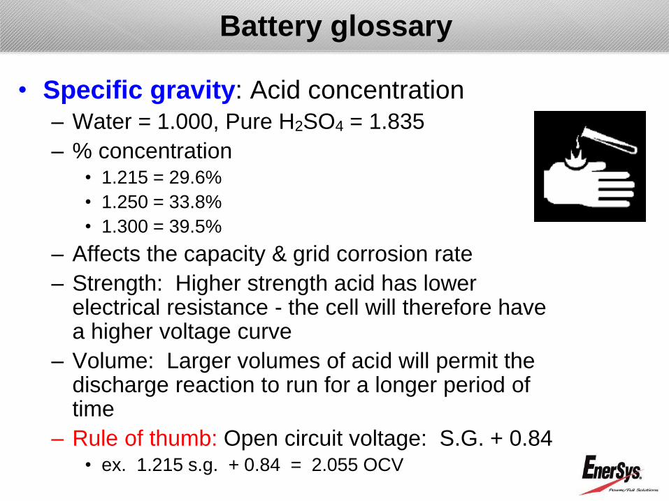
• Specific gravity: Acid concentration – Water = 1.000, Pure H2SO4 = 1.835
– % concentration • 1.215 = 29.6%
• 1.250 = 33.8%
• 1.300 = 39.5%
– Affects the capacity & grid corrosion rate
– Strength: Higher strength acid has lower electrical resistance - the cell will therefore have a higher voltage curve
– Volume: Larger volumes of acid will permit the discharge reaction to run for a longer period of time
– Rule of thumb: Open circuit voltage: S.G. + 0.84 • ex. 1.215 s.g. + 0.84 = 2.055 OCV
Battery glossary

Flat pasted plate construction
• Grid – Collects and carries current
– Provides support for active material
– Tends to grow & corrode over time
– EnerSys grids are double-hung to avoid cantilevering of plates
• Active material (Paste) – Positive = PbO2 (black, when fully charged
and healthy)
– Negative = Pb (gray)
– Primary source of chemical reaction (electricity)
– Tends to degrade (soften) with heavy use or deep cycling
• Plate = Grid + Paste
Shown: 12V VRLA plates

Self discharge
• Internal Resistance of battery acts as a small load
• Battery slowly discharges if left uncharged for an extended period of time
• Because of this phenomenon, batteries must be recharged periodically when left on open circuit
Days in storage at 25ºC
% P
ow
er
Reta
ined
The storage time is
significantly reduced
for selenium (PbSe)
and antimony (PbSb)
alloy products due to
the faster self
discharge

Battery storage & shelf life
• Freshening charges are required at the following intervals at 77ºF: – Lead-antimony/selenium:
Every 3 months
– Lead-calcium: Every 6 months
• Indoors and dry location is ideal
• Batteries must be stored away from any harmful chemicals (petroleum-based products, e.g.)
• Storage time and freshening charge intervals are directly dependent on temperature
General rule of thumb – for every
15F to 18F rise in storage temp
above 77F will reduce the
storage time by 50%

Battery glossary
• Ampere-hour (Ahr): The capacity of a storage
battery
– Based on Amperes X Hours
– Typically used in Telecom and Utility and expressed
in amp-hours at the 8hr rate to 1.75 end voltage @
25C (77F)
– Example:
• 3CC-9M will provide 25 amps for 8 hours
(25 amps x 8 hours = 200 amp-hours)
• Watts-per-cell: The power rating of a storage battery
– Typically used in UPS batteries
– Example: uses WPC @ 15 min rate to 1.67 vpc @
25C (77F)

Ratings tables
End Voltage 1.75 Vpc
Time in minutes
Cell Model 60 120 180 240 300 360 420 480
CC-03M 26.9 17.2 12.8 10.4 8.8 7.7 6.9 6.3
CC-05M 53.9 34.4 25.7 20.8 17.7 15.5 13.8 12.5
CC-07M 80.8 51.6 38.5 31.2 26.5 23.2 20.8 18.8
CC-09M 107.8 68.9 51.4 41.6 35.3 31.0 27.7 25.0
Discharge rates in Amperes with 1.215 specific gravity acid at 77F (25C)
Battery ratings are NOT linear!

Lead Acid Batteries
Grid Alloy Choices
Grid alloy history
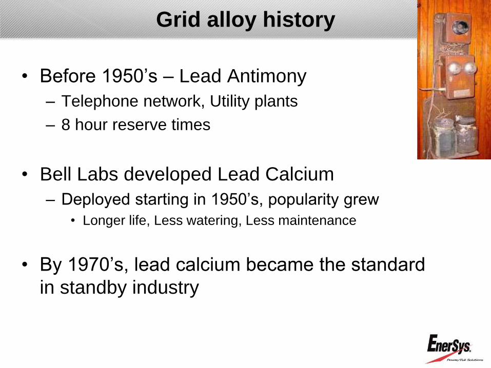
• Before 1950‟s – Lead Antimony
– Telephone network, Utility plants
– 8 hour reserve times
• Bell Labs developed Lead Calcium
– Deployed starting in 1950‟s, popularity grew
• Longer life, Less watering, Less maintenance
• By 1970‟s, lead calcium became the standard
in standby industry

Grid alloy history
• Original Lead-antimony (>5% Sb) alloy evolved into “Lead-selenium” (approx. 2% Sb) alloy – Antimony level reduced from >5% to approx. 2% and
selenium added as a grain refiner
– This reduction delays the antimony poisoning of the negative plate
– Batteries should be stable for first 5 to 6 years of service life
– After this, normal antimony poisoning will occur • Float voltage requirement will increase
• Gassing level will increase
• Water consumption will increase
– Minor threat of poisonous “STIBINE GAS” as a byproduct during severe, uncontrolled overcharging

Lead-selenium (PbSe)
• Contains 1.6 – 2.8% Antimony / 0.02% Selenium (Sometimes called Low-Antimony alloy)
• Advantages
– Is an antimony alloy, so has the high cycling benefit of antimony
– Float voltage range
– Postpones antimony poisoning by 5 to 6 years
– Initial infrequent water additions – due to large watering space
• Disadvantages
– Older cells experience antimony poisoning with all associated
disadvantages (increased water consumption, difficulty in float
matching, increased positive grid corrosion)
– Older cells don‟t float well with new replacement cell
The Lead-Acid Battery alloys

Lead-calcium (PbCa)
• Advantages
– Calcium is stable in lead-acid battery – no poisoning
– Initial float currents are low and remain low throughout life
– Water consumption is lower than antimony
– Replacement cells easily matched to older strings
– Positive grid corrosion lower due to low float currents
– Self-discharge rate lower – longer shelf life
• Disadvantages
– Not suited for daily or high cycling application
– Careful alloy control required to control long-term grid growth
– Float voltage range control via depolarization
The Lead-Acid Battery Alloys

Comparison of Float Currents:Low Sb Versus Calcium
Equivalent Years AT 77°F (25°C)
0 5 10 15 20 25
Flo
at
Cu
rren
t: M
illi
am
ps P
er
100 A
H
0
50
100
150
200
Low Sb
Ca
Expected Life, Years:
Ca Low Sb 20 13.7
Lead alloy comparison
Lead-antimony
Lead-selenium
Lead-Calcium
Water consumption
Lead-selenium
Lead-Calcium

Lead Acid Batteries
Standby Application Differences

3 Major Markets Served: Telecom/UPS/Utility
• Telecom/Broadband - 24/48 volt DC, 4 or 8 hour rate
– Wireless: Mobile Telephone Switching Office (MTSO) and Cell sites
– Wire-line: Central Offices (CO) and Outside Plants (OSP)
• UPS - 480 volt DC, 15 minute discharge
– Computer backup - Inside, clean, controlled installations
• Utility - 120 volt DC with various duration discharge with 1 minute initial and final spikes – Generation plants, transmission & distribution substations
Typical standby battery applications

• Telecommunications
– DC Power backup for local telephone service
providers, long distance, fiber optic
transmission, cellular telephone service
providers and outside plant broadband
(bundle)
– Product lines:
• Larger capacity VLA batteries
• Valve-regulated VRLA (AGM & GEL) batteries
• Racks, Cabinets electronic monitors
• Customers: Triple play or bundle packages as
well as land line and wireless providers
Standby applications

• UPS (Uninterruptible Power Supply)
– AC Power backup for a wide-range of commercial,
industrial, and government facilities
– Product lines:
• Large flooded batteries
• Large and Small Ah valve-regulated batteries
• Racks, electronic monitors
• Customers: UPS OEM, Data Centers, Government facilities
Standby applications

UPS application
• UPS service – factors that affect battery life – High current for shorter reserve time
• High current density
– Battery sized for reserve time closer to actual usage
• Typical outage 2-3 minutes vs. sizing to 15 minutes
– More cells per string
– Exposure to more discharge cycles • Blackouts, Brownouts, Generator testing

UPS application
• UPS applications are more
stressful to batteries than
telecom & Utility applications
– Higher current density due to
typical reserve times of 10-15
minutes vs. 8 hours in
telecommunications
• Less efficient utilization of active
material
• Internal resistance more of a factor due
to higher discharge currents through
each plate and post

System Comparisons
HX-F - Front Terminated 16V Bloc DXC – Wrapped Plated Flooded 2V Cell
HX - Top Terminated 12V Bloc DDm – Stackable VRLA

750kVA (0.9 Power Factor, 95% Efficiency, 240 Cells)
kWB = 710.5kW (2961WPC)
Based on 15 Minutes to 1.67VPC @25°C
Solution Model
Est Run
Time
# of
Strings
required # units/ string Cabinet/Rack Description
HX-F 16HX800F-FR 15 4 30 4 cabs, 30 units (120 Total)
HX HX500 15 6 40 6 cabs, 40 units (240 Total)
DXC 4-DXC-21B 17 1 60 2x13ft 2Tier, 2x14ft 2Tier
DDm 100-33 17 1 240 5 stacks, 6 wide and 8 high
Estimated Footprint
Solution Model Length (ft) Width (ft) Description Total sq ft
HX-F 16HX800F-FR 16.67 5.67 50" x 32" each cab 94.44
HX HX500 21.50 5.67 43" x 32" each cab 121.83
DXC 4-DXC-21B 27.00 7.00
2x13ft 2Tier, 2x14ft
2Tier w/ one 3'
aisle 189.00
DDm 100-33 34.42 5.19
5 stacks, each 6
wide and 8 high 178.54
Notes: Cabinet and DDm footprint includes a 3 foot aisle allowance for the front
Rack footprint for DXC assumes 2 racks end to end with a 3 foot aisle
UPS System size comparison

• Utilities (Switchgear & Control)
– AC Power backup for Utility companies, generally in generating plants, and substations
– Product lines:
• VLA (flooded) batteries
• Large and small Valve-regulated batteries
• Chargers, racks, electronic monitors
• Customers: Utility companies
(Generation, Transmission, Distribution),
engineering houses, nuclear power
plants, oil & gas companies
Standby applications

Standby applications
• Switchgear Requirements
– Power for intermittent outages
• 2-20 outages/year
• Not considered a high cycling
application, but must be able to
handle 20 year‟s worth of cycles
– Critical uptime issues
• Loss of electricity not tolerated

Utility application
• Duty Cycle
– Battery current required over time at a given temperature and
specific gravity and to a specified end voltage
– Typically varies over time in order to perform several different
operations, such as:
• Breaker Tripping and Closing
• Lights and Alarms
• Control Circuits
• Communications Circuits

• Utility battery selection should not be based
on Ah rating alone
Think entire duty cycle
Utility application

Typical application differences
Telecom Battery UPS Battery Utility Battery
Standby float application Standby float application Standby float application
Typ. 8hr discharge rates Typ. 15 min discharge
rates
Typ. 1hr discharge rates
Constant current
discharge
Constant power
discharge
Multi-step duty cycle
discharge
Few cycles
<10 cycles/yr
Moderate cycles
10-20 cycles/yr
Very few cycles
2-5 cycles/yr
Long duration, deep
discharges (to 1.84vpc or
1.75vpc)
Short duration, high rate
discharges (to 1.67vpc)
Short & long duration
deep discharges (to
1.75vpc)
Poor high rates Very good high rates Good high rates
CO: temp. OK
OSP: high temp
Typically temp. OK Varying temp environ.

Telecom Battery UPS Battery Utility Battery
Nominal 8 hr discharge
rate
Nominal 15 min.
discharge rate
Combination of long &
short duration rates
Thicker pos plates Thinner pos plates Moderately thick plates
Plates farther apart Plates very close Moderate plate center
High electrolyte to plate
ratio
Low electrolyte to plate
ratio
Moderate electrolyte to
plate ratio
Minimal cycling Improved cycling Moderate cycling
Poor high rates Very good high rates Reliable high rates
Good long rates Poor long rates Reliable long rates
Typical battery design differences

VLA vs. VRLA
Similarities and Differences

Similarities
VRLA VLA (Flooded)
Alloy Lead alloy Lead alloy
Grid Lead alloy, solid frame Lead alloy, solid frame
Paste Mixture of lead oxide,
acid, and additives
Mixture of lead oxide,
acid, and additives
Plate Paste filled grid Paste filled grid
Electrolyte Sulfuric acid Sulfuric acid
Chemistry Positive plate is the
life limiting member
Positive plate is the
life limiting member

What is the design difference?
Separator - difference is noticeable
• Flooded: microporous membrane
– Grooved for acid and gas movement
– Provides good short prevention
– Glass mat added to hold paste for
improve cycle life
• VRLA: Absorbent glass fiber mat
– Acid is fully absorbed - no free acid
– Must maintain contact with plates
- provides acid to plates
– Compression level is critical
– ~95% saturated to allow gas exchange
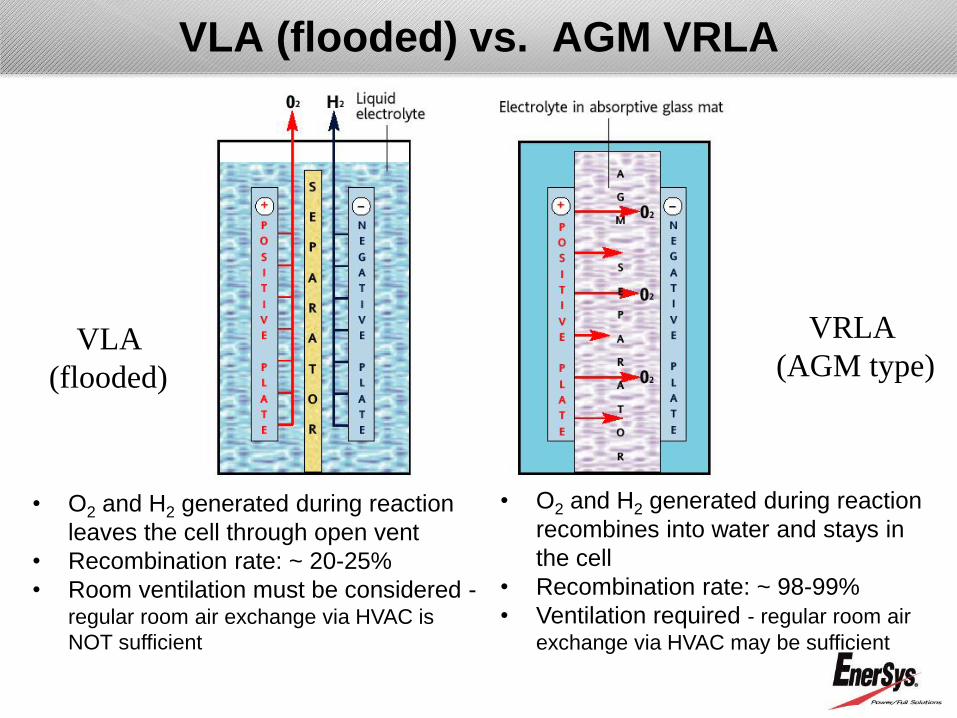
VLA
(flooded)
VRLA
(AGM type)
VLA (flooded) vs. AGM VRLA
• O2 and H2 generated during reaction
recombines into water and stays in
the cell
• Recombination rate: ~ 98-99%
• Ventilation required - regular room air
exchange via HVAC may be sufficient
• O2 and H2 generated during reaction
leaves the cell through open vent
• Recombination rate: ~ 20-25%
• Room ventilation must be considered - regular room air exchange via HVAC is
NOT sufficient

Gel VRLA
Gel VRLA
• Electrolyte held in a solid gel
mass
• Sulfuric acid and silica in
VLA type micro-porous
separator – NOT AGM
• Micro fissures within gel
mixture for gas transfer
• Oxygen recombination – no
watering
• Upon agitation gel reverts
back to liquid
• Ground transportation –
similar to liquid batteries

Benefits of AGM VRLA
• Space savings
• No water addition or monitoring of
electrolyte
• Higher energy & power densities
• Low hydrogen venting (gassing)
due to 98-99% recombination rate
• Better cycling capabilities (no
sediment)
• No free acid - “Nonspillable”
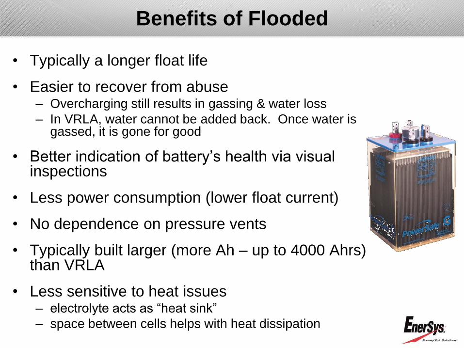
Benefits of Flooded
• Typically a longer float life
• Easier to recover from abuse – Overcharging still results in gassing & water loss
– In VRLA, water cannot be added back. Once water is gassed, it is gone for good
• Better indication of battery‟s health via visual inspections
• Less power consumption (lower float current)
• No dependence on pressure vents
• Typically built larger (more Ah – up to 4000 Ahrs) than VRLA
• Less sensitive to heat issues – electrolyte acts as “heat sink”
– space between cells helps with heat dissipation

How to choose between VLA and VRLA?
Must consider the following:
• Application
– Cycle vs. float
– Discharge rate
– Estimated service life
– Temperature
• Space & Accessibility
• Maintenance & Monitoring

How to choose?
• Application - Cycle vs. Float
– VRLA
• Element compression aids in cycling
• Overcharge & undercharge more critical
• Better cycling than Flooded
• In most cases, VRLA batteries are made with lead-calcium alloy
– Flooded • Wrapped plate improves cycling
• Better able to withstand extreme usage
• Visually able to detect over / undercharge

How to choose?
• Application - Discharge rate
– Flooded
• Able to vary acid volume ratio depending on application
• Plate thickness and acid volume play a role
– VRLA
• Lower resistance of AGM aids in high rates
• Limited acid volume affects duration
• Higher concentration acid (1.300) used
• More sensitive to low cutoff voltages
– Leading to development of dendrite shorting

How to choose?
• Application - Service life
– Flooded • Been around a long time
• Proven history of batteries with longer than 20 yr service life
• Modes of failure are well understood
– VRLA • Relatively short history compared to flooded
• Modes of failure are being studied and making improvements
• Selection also depends on site accessibility
– Depth of discharge is critical to service life

How to choose?
• Application – Temperature
– Flooded • Better at temp variation than VRLA
• High temp results in higher grid corrosion & grid growth
• Higher grid corrosion results in increased gassing - results in higher water loss and shorter life
– VRLA • Sensitive to high temperature
• High temp = high grid corrosion/grid corrosion = high gassing = higher water loss
• Excessive water loss results in premature failure

How to choose?
• Flooded
– Requires larger foot print for
same energy density
– Must consider access space
for maintenance
– Must consider ventilation
requirement & spill
containment
– Proven reliability
• VRLA
– Takes up less space for
same energy density
– Reduced maintenance
– Regular room air
exchange is sufficient;
however, avoid air tight
rooms
– Do not turn off HVAC
system while the batteries
are on charge
Space / Maintenance Considerations

Material & Battery Selection Guidelines

• Limited Oxygen Index (LOI)
– Used to rate the ability of material to support a flame
– LOI refers to the minimum oxygen level required to
sustain a flame. If the LOI is above ~20, the plastic
will be self-extinguishing
• Typical atmospheric level LOI is approx. 18
PC-ABS PVC FR-PP PC SAN Styrene
LOI: 32 32 28 25 18 18
Plastics choices

• Common jar material choices
SAN FR-PP PVC PC
Cost $ $$ $$ $$$
Strength 1 2 2 3
LOI 18 28 >32 25
Plastics choices
• SAN, PVC & PC available in transparent mat‟l & used in flooded cells
• PP & PVC available in opaque material & used in VRLA cells

Jar material choices - Flammability
• Flammability plays a big factor in preventing
battery fire

Battery selection
• There are many items to be considered when selecting a battery for stationary use – Application
– End Voltages
– AH Sizes
– Power Density
– Ventilation
– Temperature
– Space (room/cabinet) limitations
– Budget
– Expected service life of the installation
– Experience level of maintenance personnel
Battery sizing
• Some customers have internal battery-sizing computer programs
• EnerSys provides an online Battery Sizing Program (BSP) for flooded batteries – https://bsp.enersys.com/bsp/globalLocations.do
• IEEE 485 provides guidelines for sizing batteries – Temperature correction
– Design margin
– Aging factors
– Initial capacity vs. Peak capacity
• Battery system requirements typically dictated by equipment in place – Runtime based on Ah rating
– Single Cell (2V) vs. Multiple Cell (4, 6, or 8V)

Battery sizing
• Design margin – How much do you want to oversize the battery?
– Default design margin is 1.0
– Typical design margin value is 10% or 1.1
• Aging factor – Where do you want the battery capacity at the end of life?
– IEEE says the batteries are at the end of life at 80% capacity
– If you want the batteries to be at 100% capacity at the end of life, then the aging factor has to be 1.25

• Heat accelerates chemical activity and cold
slows it down
• Low temperature will reduce available battery
capacity by approx. 0.5% per degree F
• High temperature will
– Increase capacity
– Shorten life
– Increase internal discharge rate
– Raises charging current
– Increases the watering interval
Temperature effect
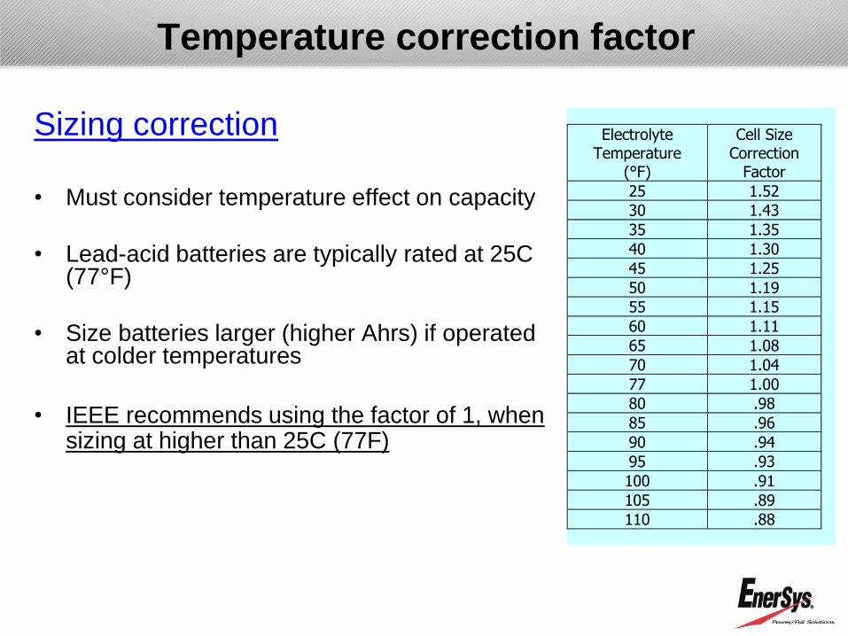
Sizing correction
• Must consider temperature effect on capacity
• Lead-acid batteries are typically rated at 25C (77°F)
• Size batteries larger (higher Ahrs) if operated at colder temperatures
• IEEE recommends using the factor of 1, when sizing at higher than 25C (77F)
ElectrolyteTemperature
(°F)
Cell SizeCorrection
Factor
25 1.52
30 1.43
35 1.35
40 1.30
45 1.25
50 1.19
55 1.15
60 1.11
65 1.08
70 1.04
77 1.00
80 .98
85 .96
90 .94
95 .93
100 .91
105 .89
110 .88
Temperature correction factor

VLA Configuration & Terminology
• Non-seismic
• Seismic – Zone 2, Zone 4
• 2-Tier, 2-Step, etc.
• Single string
• Parallel string
• Terminal Plates / Overhead Buss Bar
• Perpendicular & Parallel Configurations
Two-Tier Seismic Rack
Battery Charging

• Charging – keeps the batteries at full state of
readiness so they can deliver the expected
capacity at the time of need
– Recharging following a discharge
– Float charging
– Equalization charging
Types of Charging

Recharging following a discharge
– Approx. 105 to 110% of the Ahr removed on discharge
should be returned to fully recharge the battery
Types of Charging – Recharge Following A Discharge
– If not fully recharged, the residual lead sulfate remains
on the plates (white residue, which may be hard to
detect in the early stages)
– If the cell is not recharged or undercharged for an
extended period, the lead sulfate hardens
– Hardened lead sulfate will permanently kill the capacity
and can result in cell shorting

Plate Sulfation Progression

Float charging
– Necessary to keep the battery at 100% state of charge
– Counters the battery‟s self discharge reaction
– Too low float voltage
• undercharged battery
• can cause plate damage
– Too high float voltage
• overcharges the battery
• excessive grid corrosion and loss of water
– Temperature compensated charge voltage recommended
to prolong battery life
– Float charging does not result in temp. rise
Types of charging – Float Charging

• DC power supply will keep the batteries fully
charged – adjust the power supply to proper float
values
• Float voltage – Correct float voltage maximizes
battery performance and service life
Nominal Acid
Specific gravity
Allowable float
voltage based
on total battery
voltage
Allowable
individual cell
voltage
1.215 2.20-2.25 2.12-2.29
1.250 2.22-2.27 2.15-2.32
Types of charging – Float Charging
Note: Above table is for lead calcium flooded batteries

Charging Issues
• Overcharging causes:
– Accelerated aging
– Excessive polarization of the positive plate =
accelerated corrosion
– Generates more free oxygen = accelerated corrosion
– Excessive Gassing
– Shedding of active material
– Increased water consumption = frequent watering
– Increase in heat generation

Charging Issues
• Undercharging
– Means that the battery does not get
fully charged
– Causes plate sulfation
– Build-up of lead-sulfate crystals on
plates
– Loss of capacity which could be
permanent
– Plate deformation
– Equalize or boost charge may fully or
partially recover depending on severity
of undercharging

• Equalization charging
– Used to bring batteries up to full state of charge
– Needed if charged to less than minimum float voltage –
equalization will restore the proper float voltage
– Results in gassing which in-turn mixes the stratified acid
– Used to even out cell to cell float voltages and capacity
differences that may develop over time
– Too frequent equalization shortens the battery life
• Need to equalize does not imply malfunction or
failure to support the load
Types of charging – Equalization Charging

Nominal acid
Specific gravity
Equalize when
lowest cell in string
reaches this voltage
Equalize voltage per
cell
1.215 2.12 2.33-2.38
1.250 2.15 2.38-2.43
• Equalizing charge - follow manufacturer‟s
recommended voltage
– If the lowest cell in string on float reaches the below
voltage
– If subjected to frequent discharges
– Unless trouble shooting, equalization charges are
unnecessary
Types of charging – Equalization Charging
Note: Above table is for lead calcium flooded batteries

• Equalization charge duration
– Charging time varies depending on condition of the
battery
• time on open circuit
• storage temperature
• charge voltage
– When equalized as a string, it usually takes between
8 to 24 hours, but may take up to 100 hours
– Stop equalizing
• 3 successive voltage readings are the same
• the lowest cell is less than 0.05 volts below the average of
the string
Types of charging – Equalization Charging
Battery Maintenance Checks
• In general the types of checks to be made during
the periodic maintenance include:
– System charging voltage
– Ambient / Battery temperatures
– Inter-unit connection hardware resistance or tightness
– Individual battery float voltage
– Battery system capacity test
• Have a consistent maintenance program
• Follow manufacturer‟s recommendations or IEEE
guidelines
– IEEE-450 (VLA), IEEE-1188 (VRLA)

• If the charging equipment does not have the
required equalizing potential
– Single cell charger may be paralleled across the affected
cell while still part of the overall battery
– It will provide an over-voltage to the subject cell
– This type of charger requires AC isolation from DC to
prevent possible ground faults and shocks
• Buy chargers with transformer isolation feature
Types of charging – Single Cell Charging

Charger selection
• Battery charger must have at least two
capabilities:
– Electrical filtering to protect the cells from AC ripple
• may lead to shedding where active material from flooded
battery falls to the bottom as sediment
• too much will cause cell shorting
– Temperature compensation to prevent overcharging
or undercharging
Temperature compensate by 2.8mV (0.0028V)
per degree F deviating from 77F
• Add 2.8mV per degree F below 77F
• Subtract 2.8mV per degree F above 77F

Specification Writing

Writing battery specifications
• Simple and relevant battery specification will
facilitate the selection of the right battery
• It results in ……..
– Satisfactory life
– Less remedial maintenance
– Capital savings
– Most reliable back-up power system

Common Pitfalls
• Do not simply cut & paste existing documents
“Lead acid batteries shall be AGM VRLA type
with battery containers clearly marked with high
and low acid level lines.”

Common Pitfalls
• Do not leave it up to individual interpretation
“Battery jars must fit comfortable, within battery
building, with plenty of room for servicing and
replacing cells.”

Common Pitfalls
• Define the load, duration, end voltage, and
temperature
“Number of cells is 60 with a minimum of 280 AMP
HOUR capacity of each cell.”

Writing Style
• Avoid using ambiguous and wasteful phrases
“except as otherwise specified”
“unless otherwise shown or directed"

Writing Style
• Use present tense
Try to avoid “will, shall, should, & may”
• Above words brings into question whether the
parameters are mandatory or not
• Present tense makes language clear and direct &
prevents „specification creep‟

Technical Aspects
• Three major areas
1. Application definition
• Describe the battery and its usage fully
2. Battery system preference
• Summarize the customer‟s preferences in terms of
the battery type and features
3. Requirements
• Define specific features or criteria that the battery
must meet as determined by the customer

Technical Aspects
• Application definition
• Describe application
• Become familiar with IEEE standards for stationary
batteries
• Areas to define
• Environment
• Duty cycle
• Recharge method
• Maintenance issues

Technical Aspects
• Environment –
temperature, seismic,
vibration, etc. • Ambient temperature – why it is
important
• Cold = Larger battery
• Hot = Shorter life
• Options based on temperature
• High temperature plastic
cover/container material
• Outer steel sleeve
• Electrolyte specific gravity

Technical Aspects
• Battery system preferences
• Identify customer preferences
• VLA vs. VRLA
• Single cell vs. Multi-cell jars
• Parallel string vs. Single string
• Ancillary equipment
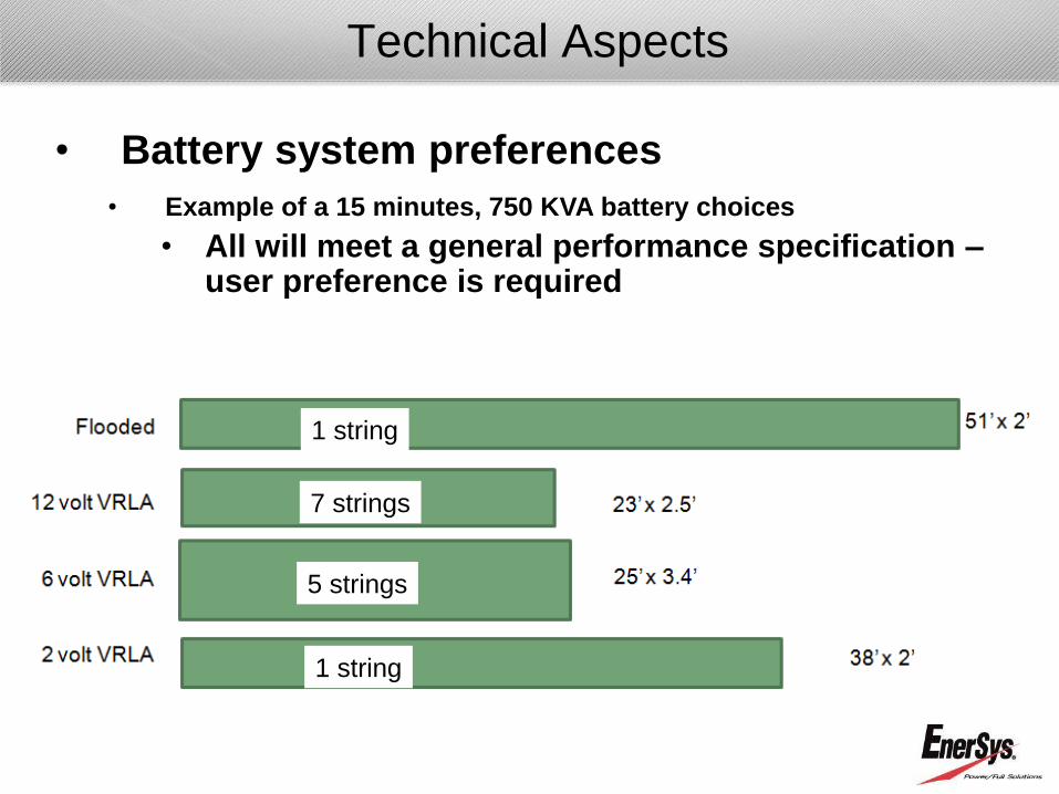
Technical Aspects
1 string
7 strings
5 strings
1 string
• Battery system preferences
• Example of a 15 minutes, 750 KVA battery choices
• All will meet a general performance specification – user preference is required
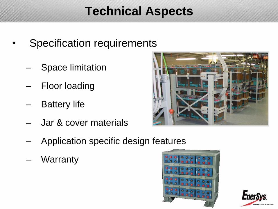
Technical Aspects
• Specification requirements
– Space limitation
– Floor loading
– Battery life
– Jar & cover materials
– Application specific design features
– Warranty

Factors affecting performance and life

EnerSys Reserve Power Flooded Cells
Life vs Average Operating Temperature
10
20
30
40
50
60
70
80
90
100
110
75 80 85 90 95 100 105 110 115 120 125
Average Operating Temperature (°F)
Perc
en
t o
f N
om
inal L
ife (
%)
General rule of thumb – for every 15F to 18F
(8C to 10C) rise in operating temp above 77F
will reduce the service life by 50%
Temperature - battery life relationship

Inspection & maintenance guidelines
• IEEE 450 (VLA) & IEEE 1188 (VRLA)
outlines inspection & maintenance
guidelines
• Obtain the latest document at
www.ieee.org

• Do not over estimate your
strength
Handling cells
• Have proper tools to handle
cells – Two wheeled carts tip forward and
backward – causing acid spills with
flooded cells

Battery inspection
• Preliminary external inspection should occur upon arrival of battery shipment: – BOL matches expectation
– Damage to packing material
– Wetness or stains indicating electrolyte leakage
– Issues found at this point should be noted to freight carrier before signing for product
• Secondary (detailed) Inspection to occur within 15 days of receipt – If electrolyte is below proper levels, contact
EnerSys representative
– Check the received materials match the packing list
– Carrier should be contacted for any “hidden” damages
• Beware of Static Electricity!

Key points to check during installation
• Batteries being lifted / moved using approved battery straps – Lifting / moving batteries by the terminals is NOT
recommended and will VOID the warranty
– Failure to use Styrofoam block (provided) may damage cells and lead to short-circuit
• Rack lubricant is to be EnerSys Pro-Slide or Dow Corning Silicon Compound #111 – Petroleum-based lubricants will CRACK the jar
• Cells should be carefully positioned – Banging of jars can cause irreparable damage
• NO tools are to be used to pry cells into position

Installation of intercell connectors
• Remove grease & inspect terminals posts
• Any tarnishing or discoloration of posts requires cleaning
• Intercell connectors are to be cleaned prior to installation
• NO-OX-ID grease must be applied to each post/connector prior to connection
• Each connection (bolts, washers, connectors, and nuts must be properly torqued using a calibrated torque wrench
• All specified washers & other hardware must be used
• “Rounded” edges of washers are to face intercell connector / battery post
• Read connector resistance to
ascertain connection quality
An improper connection could
result in catastrophic battery
failure

Catastrophic failures
Caused by improper connection torque!

• Do NOT place the cells near
radiant heat source (ex. portable
heaters, heating ducts, etc.)
• Do NOT expose cells to the direct
sunlight – UV rays will react with plastic jar and cover
– Sunlight will heat the exposed cells
• Do NOT allow electrolyte to freeze (fully charged battery may not freeze, but
discharged battery may freeze) – do not store or
operate below 32F (0C)
Installation location

Impedance & conductance
• The objective of „impedance‟ testing is
correlating the change in the output
signal to changes in the components
of the actual cell
• The desire is to detect physical changes and chemical
changes in the cell
– Physical changes – want to determine mechanical defects,
temperature effects, decrease in grid wire diameters, etc.
– Chemical changes – want to determine changes in the paste,
changes in acid concentration, changes in amount of lead sulfate,
change in crystal structure of the plates, etc.

Impedance & conductance
What do these values mean?
• Cells are measured and a value is given. This value is a
combination of all impedance measurements: resistance +
capacitance + inductance (This is the easy part)
• This combination value must then be interpreted to determine if
a cell is good or bad (This is the hard part)
• This value is also used to „predict‟ if a cell is going to be good or
bad in the future (This is the unrealistic part)

• Internal ohmic measurement is a tool that can be useful for trending batteries – Use with flooded batteries is questionable because
internal resistance change may not be observable
• Taking a baseline reading at the time of installation is very important
• Capacity testing is the only surefire way to verify cell performance
Maintenance – Internal resistance (impedance /conductance)

Impedance changes due to:
• Gassing:
– Gas (H2 and O2) bubbles develop on plates during charge cycles
creating less surface area
• Sulfation:
– Deposits of sulfur ions on Plates and become harder (crystallized)
over time, more difficult to remove
• Electrolyte volume:
– Loss of electrolyte due to gassing
– Recent water addition to flooded cells
– Dryout for VRLA batteries
• Probe location & Meter model
– Measurement location & meter type can make difference

• Lead-Acid Battery is a sacrificial design with
unavoidable degradation over time
– Highly chemically active environment
– Corrosion of positive plate grid structure
– Converts base material to:
• Lead dioxide
• Lead peroxide
• Lead sulphate
• Even under ideal conditions
• Positive Grid Corrosion commonly results in
“Positive Plate Growth”
Battery aging

Battery aging
• Effects of Positive Plate Grid Corrosion:
– Expansion of the positive plate
• Occupies more volume
– Decrease in grid cross-sectional area
– Weakening of grid and straps
– Loss of electrical contact with active material
• Higher resistivity & Lower conductance
– Active material shedding (sediment)
– Loss of conductance
– Reduced capacity

• Failure modes due to aging:
– Permanent Loss of capacity
– Increased internal resistance
– Obstruction of active material in discharge reaction
– Post seal leakage
– Cracked cover
– Internal short circuit
– Loss of physical strength
– Failure of conduction path
Battery aging
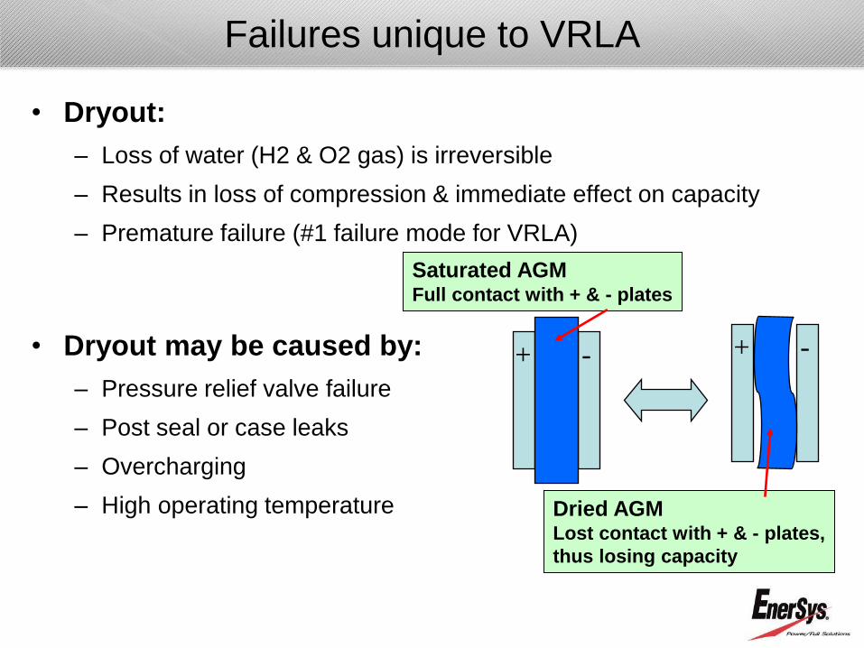
• Dryout:
– Loss of water (H2 & O2 gas) is irreversible
– Results in loss of compression & immediate effect on capacity
– Premature failure (#1 failure mode for VRLA)
• Dryout may be caused by:
– Pressure relief valve failure
– Post seal or case leaks
– Overcharging
– High operating temperature
Failures unique to VRLA
+ - + -
Saturated AGM Full contact with + & - plates
Dried AGM Lost contact with + & - plates,
thus losing capacity

Charger selection
• Battery charger should have at least two
capabilities:
– Proper charger output filtering to protect the cells from
AC ripple - which may lead to shedding where active
material from flooded battery falls to the bottom as
sediment – too much will cause shorting
– Temperature compensation to prevent overcharging or
undercharging
– The consensus is that AC ripple will prematurely age
the batteries and accelerate corrosion & shedding

• Proper installation & maintenance will make
batteries last longer and perform to its requirements
• Battery installation & maintenance should be done
by personnel knowledgeable of the battery and the
safety procedures involved
• Installation & maintenance must be done in
consistent manner to avoid discrepancies
Installation & Maintenance

Improper installation
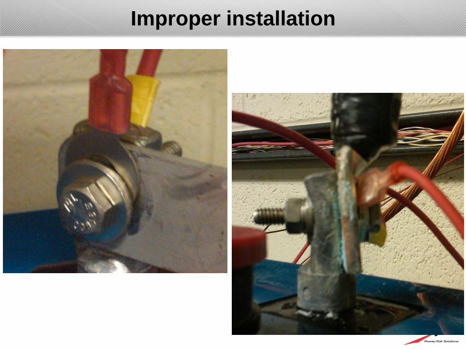
Improper installation

Improper installation
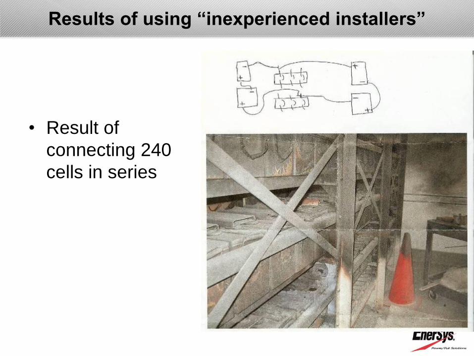
Results of using “inexperienced installers”
• Result of
connecting 240
cells in series

Periodic Maintenance assures:
Maximum System Reliability
Longest Battery System Life
Indication of When to Adjust the “System”
Indication of When to Replace a Cell
Indication of When to Replace the System
Why do the battery system maintenance?

Hydrogen gas emission
• ALL batteries emit gas (H2 & O2) during charging
• Hydrogen concentration above 4% is explosive
– Hydrogen monitors available
– Never ignore hydrogen alarm
• NEVER place ANY batteries in air tight area with
no ventilation
• Charging current determines the amount of gas
generated
– Limit charge current
– Float charging produces little gas

Sensory checks
Hearing
“sizzle” is not good
Visual
distorted labels or case, melted terminal
grease, damaged containers or cracked cover,
visible leaks
Smell
odor of rotten egg (H2S)

Maintenance – visual inspection
• A set of eyes and a flash light are very important
tools in detecting any abnormalities
– Acid level
– Sulfate crystals
– Seal conditions
– Debris inside cells
– Sediment level
– Presence of acid on cover & container (VRLA)
– Discoloration (VRLA)
– Bulging (VRLA)

• Visual inspection
– Inspect the battery rack for possible structural
deterioration (rusting, corrosion, bending,
etc….)
– Check electrolyte level on VLA cells
– Inspect each battery jar, cover, posts and seals
for deterioration
– Examine the color of plates (pos plates should
be dark chocolate to black color)
– Look for sulfation with a flash light
– Check the sedimentation level
Maintenance – visual inspection

Battery disposal
• Dispose cells in accordance with Federal, State,
and Local ordinances – DO NOT THROW AWAY
LEAD-ACID BATTERIES WITH COMMON
TRASH
• Contact EnerSys for proper methods and
approved disposal handlers

• Calibrate meters to avoid misreading
• Calibrate torque wrench to minimize damage
to posts and connectors
Maintenance - Calibration

Maintenance - Capacity testing
• The actual measurement of battery‟s ability to
provide back-up power for a predetermined
amount of time
– Specified amount of current (amperes) to a certain end
voltage for a determined period of time
– Examples
• UPS (15 min rate to 1.67vpc)
• Substation (1 hour rate to 1.75vpc)
• Telecom (8 hour rate to 1.75vpc)
• Verification of manufacturer‟s published rating or
system design performance parameters

Maintenance – Capacity testing
• Capacity testing requires …. – Equipment (load bank, data collection devices, back-
up power – generator or temporary battery bank, etc…)
– Battery knowledge • Ability to detect and jump out a bad cell during testing
• Verification of load current
• Decision to interrupt testing
• Once a cell voltage falls below 1.75 volts, it will decline at a rapid rate, and the testing should be interrupted before that particular cell goes into reversal
• Test can be halted while the cell is bypassed – for 10% of total test time
• Capacity testing should be done by battery knowledgeable professionals

Maintenance – Capacity testing
• Capacity testing requires ….
– A fully charged battery properly floated at
recommended voltage, balanced cell potentials, and
acid gravities – some cases may require equalize
charge
– Battery must be on float for at least 72 hours prior to
test – especially important following equalization
– All connections (intercell, inter-row, and inter-aisle)
must be optimized to lowest resistance
– Usage of proper discharge load

• Trending - Keep maintenance record to track changes – Connection resistance
– Float current
– Float voltage
– Temperature
• Capacity testing – IEEE recommendation – A performance test should be made within the first
2 yrs of service
– The interval should not be greater than 25% of the expected life
– Annual testing should be made on any battery
showing signs of degradation or has reached 85%
of the expected life
Maintenance - record keeping

• Good record keeping is a valuable tool – Use manufacture‟s form or your company‟s
record log
– Keeps track of trend
– Needed for warranty verification
• Follow maintenance recommendations from the manufacturer
• May follow IEEE-450 and IEEE-1188‟s recommended maintenance practices
• Review maintenance data
• Early detection is key!
Maintenance - record keeping
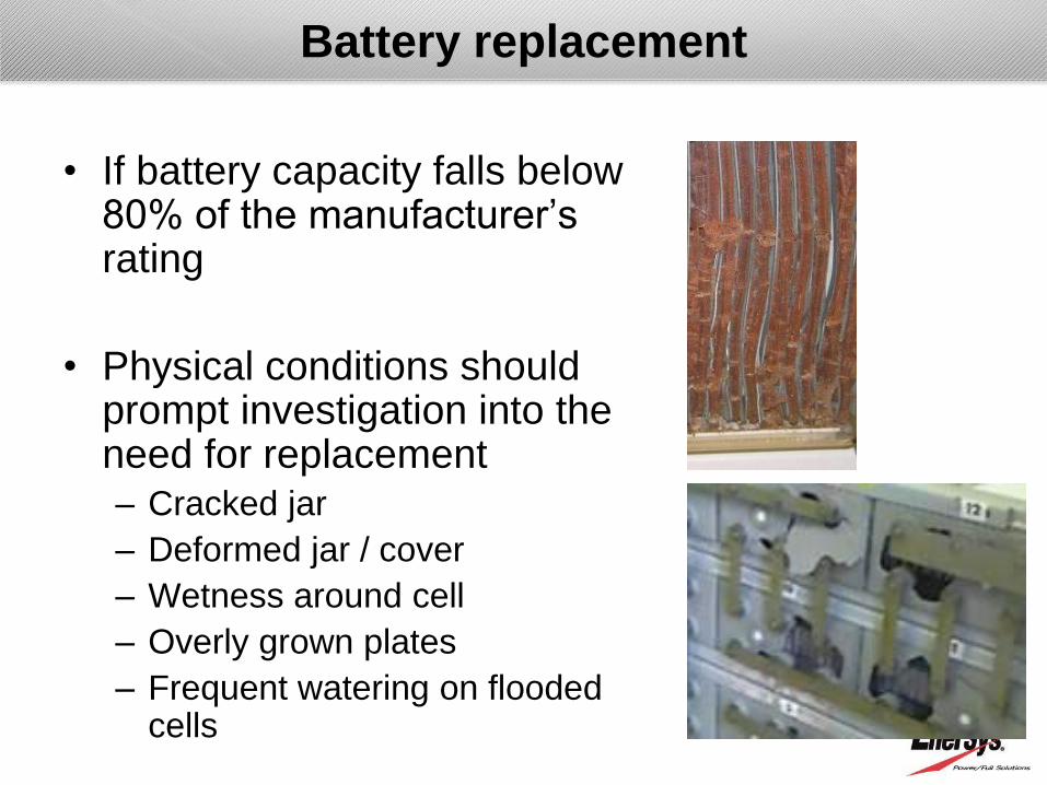
• If battery capacity falls below 80% of the manufacturer‟s rating
• Physical conditions should prompt investigation into the need for replacement – Cracked jar
– Deformed jar / cover
– Wetness around cell
– Overly grown plates
– Frequent watering on flooded cells
Battery replacement

• Removing a cell from string
– String voltage must be adjusted properly
– Identify and replace the cell in question through
early detection of possible problem – importance of
regular maintenance
Battery replacement

• If cell voltage is below 2 volts on float and can‟t
raise the voltage through equalization,
– Replace as soon as you can
– Cell may have internal short and have substantially
self-discharged
– Will limit the string performance
– Regular maintenance check should minimize the
length of time you are exposed to the risk
Battery replacement

• Mixing different size batteries within a string is
NOT recommended due to uneven float voltage –
may lead to long term damage
• Mixing different specific gravity and different alloy
batteries within a string is NOT allowed because
they float at different voltages
• Mixing different manufacturer‟s batteries within a
string is NOT recommended
• Mixing VLA and VRLA within a string is NOT
recommended
Battery replacement

Battery replacement – what not to do!

• Understand lead acid battery fundamentals
• Know different applications
• Choose the right battery for the application
• Size the batteries properly
Summary

Thank you! Any Questions?