AGARD AG 304
68
P273135 19 AGARD-AG-304 < • Q ec < < AGARDograph No. 304 Standard Fatigue Test Specimens for Fastener Evaluation ORIS .RD DISTRIBUTION AND AVAILABILITY ON BACK COVER
-
Upload
greatsteel -
Category
Documents
-
view
32 -
download
0
description
Standard Fatigue Test Specimensfor Fastener Evaluation
Transcript of AGARD AG 304
P273135 19 AGARD-AG-304
< •
Q ec <
<
AGARDograph No. 304
Standard Fatigue Test Specimens for Fastener Evaluation
ORIS .RD
DISTRIBUTION AND AVAILABILITY O N BACK COVER
si?

708848
AGARD-AG-304
NORTH ATLANTIC TREATY ORGANIZATION
ADVISORY GROUP FOR AEROSPACE RESEARCH AND DEVELOPMENT
(ORGANISATION DU TRAITE DE L'ATLANTTQUE NORD)
88 / C O 4 ^ A ^ g-g
COOAT; £ 0 L , , n
As/W
AGARDograph No. 304
STANDARD FATIGUE TEST SPECIMENS
FOR FASTENER EVALUATION
by
Robin Cook Materials and Structures Department
Royal Aircraft Establishment Farnborough, Hampshire GUI4 6TD, UK
This AGARDograph was sponsored by the Structures and Materials Panel of AGARD.

THE MISSION OF AGARD
The mission of AGARD is to bring together the leading personalities of the NATO nations in the fields of science and technology relating to aerospace for the following purposes:
— Exchanging of scientific and technical information;
— Continuously stimulating advances in the aerospace sciences relevant to strengthening the common defence posture;
— Improving the co-operation among member nations in aerospace research and development;
— Providing scientific and technical advice and assistance to the Military Committee in the field of aerospace research and development (with particular regard to its military application);
— Rendering scientific and technical assistance, as requested, to other NATO bodies and to member nations in connection with research and development problems in the aerospace field;
— Providing assistance to member nations for the purpose of increasing their scientific and technical potential;
— Recommending effective ways for the member nations to use their research and development capabilities for the common benefit of the NATO community.
The highest authority within AGARD is the National Delegates Board consisting of officially appointed senior representatives from each member nation. The mission of AGARD is carried out through the Panels which are composed of experts appointed by the National Delegates, the Consultant and Exchange Programme and the Aerospace Applications Studies Programme. The results of AGARD work are reported to the member nations and the NATO Authorities through the AGARD series of publications of which this is one.
Participation in AGARD activities is by invitation only and is normally limited to citizens of the NATO nations.
The content of this publication has been reproduced directly from material supplied by AGARD or the author.
Published November 1987
Copyright © AGARD 1987 All Rights Reserved
ISBN 92-835-0429-1
Printed by Specialised Printing Services Limited 40 Chigwell Lane, Loughton, Essex IG10 3TZ
PREFACE
Aircraft fatigue is a very expensive phenomenon in terms of inspection, of maintenance and repair and of decreased aircraft availability. Hence, design for good fatigue performance remains of great importance. Mechanically fastened joints quite often turn out to be the fatigue critical elements in aircraft structures. Recently, an extensive co-operative programme coordinated by the AGARD Structures and Materials Panel was completed in which the fatigue performance of a wide range of fastener systems were evaluated.
During this programme, which also used a variety of specimen configurations, the desirability of a limited number of standard specimens to facilitate fastener evaluation in the future, became apparent. Hence, the Structures and Materials Panel decided to set up a Working Group that would try to define a limited number of recommended specimen configurations, on the basis of a co-operative test programme.
This programme, which was very ably co-ordinated by Mr. R. Cook of the Royal Aircraft Establishment has now been successfully completed and the present report contains the results of this collaborative effort.
J.B. de Jonge Chairman, Working Group on Standard Fatigue Test Specimens for Fastener Evaluation

SUMMARY
An AGARD coordinated programme which examines the fatigue performance and joint characteristics of a number of mechanically fastened joints has been completed. This report describes the programme which examines mechanically fastened joints with 1) no or low secondary bending and 2) with high secondary bending. In part 1, three types of joint are assessed which exhibit no, low and high amounts of load transfer by the fastener. The no load transfer joint was rejected and the low and high load transfer joints were considered to be equivalent in rating fastener systems. In part 2, three types of single shear joint are considered. They are compared on the basis of load transfer and secondary bending characteristics and also on the fatigue endurance with a range of fastener systems installed. Only one joint, the UK designed Q-joint, adequately fulfilled the requirements of a standard joint for fastener evaluation purposes.
L'AGARD ("Advisory Group for Aerospace Research and Development" = groupe consultatif pour la recherche et les realisations aerospatiales) a mene a bien un programme coordonne d'examens des performances en fatigue et des caracteristiques de solidite de tcnuc d'un certain nombre de liaisons par fixation mecanique.
Le present expose decrit le programme qui traite des jonctions mecanique presentant
(1) une manifestation faible ou nulle de flexion secondaire, (2) une flexion secondaire importante.
Dans la premiere partie, on examine trois types de liaison qui revelent un niveau de transfert de charge par la fixation respectivement nui, faible et eleve. On a ecarte la solution d'une liaison sans aucun transfert de charge et estime qu'un transfert de charge faible ou eleve constituait un bon equivalent pour revaluation des systemes de fixation. Dans la deuxieme partie, on traite trois types de liaison a cisaillement simple. On les compare entre eux en etudiant le transfert de charge et les caracteristiques en flexion ainsi que la resistance a la fatigue d'une serie de dispositifs de fixation posee. Un seul systeme, le modele a pression dynamique concu par les Britanniques, a satisfait convenablement aux conditions imposees a un assemblage c<uiiant destine a 1'evaluation des fixations.
i \
CONTENTS
Page
PREFACE iii
SUMMARY iv
1. INTRODUCTION 1
2. PROGRAMME OVERVIEW 1
2.1 No or low secondary bending programme 1 2.2 High secondary bending programme 1
3. STANDARD SPECIMEN DESIGNS 2 3.1 No load transfer specimens 2 3.2 Low load transfer specimens 2 3.3 High load transfer specimens 3 3.4 Specimen designs with high secondary bending 3 3.5 Specimen requirements 3
4. FASTENER SYSTEMS 3 4 . 1 111 I O K in p la in ho le (1 A and 2 V) 4
4.2 HI-LOK in cold-worked hole (IB and 2B) 4 4.3 HI-TIGUE in plain hole (1C and 2C) and HI-TIGUE in cold-worked hole (2D) 4 4.4 HUCK-EXL(ID) 4
5. TESTING PROGRAMMES 4 5.1 No or low secondary bending test programme 4 5.2 High secondary bending test programme 5
6. RESULTS AND DISCUSSIONS 5 6.1 Results and discussion of the no or low secondary bending tests 5
6.1.1 Low and high load transfer joints 5 6.1.2 No load transfer joints 6
6.2 Results and discussion of the high secondary bending tests 6 6.2.1 Load transfer and secondary bending results 6
6.2.2 Fatigue test results 7
7. CONCLUSIONS AND RECOMMENDATIONS OF PART 1, NO OR LOW SECONDARY BENDING 8
8. CONCLUSIONS AND RECOMMENDATIONS OF PART 2, HIGH SECONDARY BENDING 8
References 9
Tables 10
Figures 27
Annex 1 Fastener fits 39
Annex 2 Pin, collar and nut part numbers used in investigation 41
Annex 3 Load transfer and secondary bending measurements 42
Annex 4 Importance of scatter 43
Annex 5 Primary fatigue crack origins 45
Annex 6 Q-joint assessment 57


1 INTRODUCTION
The most common site of fatigue crack initiation in aircraft structures is from a fastener hole. In consequence there have emerged numerous fastener systems which claim to improve the fatigue life of the joined components. The design engineer requires to know how these fastener systems will perform in his particular application such that he may choose a safe but economic solution. This requirement was recognised by AGARD and two coordinated programmes have been completed which have addressed this problem. The 'Critically Loaded Hole Technology'( 1) programme was a pilot programme which established that consistent fatigue data can be generated in complex fatigue tests between a number of participating countries. It examined principally the effects of hole quality on the fatigue performance of open hole and low load transfer joint specimens. A comprehensive follow on programme, the Fatigue Rated Fastener Systems (FRFS) programme(2), has now been completed. This examined the fatigue performance of a range of fastener systems in many different joint configurations in different materials with a selection of hole preparation techniques and installation parameters. A large amount of valuable design data was generated on the different specimen types. Comparison of different test data was achieved using core programmes of specified parameters in which all countries participated.
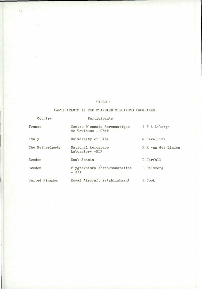
In order to facilitate such comparisons in future work it is necessary that a number of standard fatigue specimen geometries are defined and used in conjunction with the standard loading sequences that have been developed in recent years. Accordingly an AGARD group entitled Standard Mechanical Joint Fatigue Specimens' was established(3) with the task of defining a number of standard joints for fastener evaluation. The aim was not to design new joints, but to assess in some detail a number of the joints used in the FRFS programme. This is the final report of the AGARD working group, the participants of which are given in Table 1.
2 PROGRAMME OVERVIEW
The most important requirement of any standard specimen is that it should be representative of the structural feature which it is to simulate. In the case of joints, the main parameters which need to be represented are the amount of load transferred by and bypassing the fastener, the amount of secondary bending and the way in which these are controlled. The FRFS programme concluded that the primary parameter is in fact secondary bending. Accordingly the standard mechanical joint programme is split into two parts. Part 1 considers joints with no or low secondary bending and is described in section 2.1. Part 2 considers joints with high secondary bending and is described in section 2.2.
2.1 No or low secondary bending programme
In aircraft wing construction there are many areas which exhibit no or low secondary bending. Examples of this are span-wise joints, either skin-to-spar or skin-to-stiffener. The skin-to-stiffener joint will contain very low load transfer and should not be a fatigue-critical area. The skin-to-spar joint will for the most part be a low load transfer situation but depending on local design may have a high load transfer near the wing root and become fatigue critical.
Chord-wise joints are on the other hand predominantly high load transfer situations. Where double shear butt joints occur (i.e. no secondary bending) fatigue resistance is generally good. It is arguable therefore whether this type of joint is fatigue-critical. Chord-wise joints with single shear fasteners generally exhibit significant amounts of secondary bending and are considered in Part 2 of this exercise (section 2.2).
It is therefore necessary in this part of the programme to consider a number of joints which exhibit various degrees of load transfer and to pose the question:
Do all of the joints considered, rate fatigue resistant fastener systems in the same way?
There was conflicting evidence from the FRFS programme on this question. If this criterion is satisfied for all of the joints considered then only one specimen type needs to be defined as a standard. If this criterion is not satisfied, then a minimum number of joints need to be selected.
Many laboratory joint specimes with no or low secondary bending are intended to be as realistic as possible. Thus many contain several fastener rows and several fasteners per row. On the other hand there are many simple and much cheaper joints which only contain one or two fasteners. The main requirement for a standard specimen is that it should produce a rating of fastener systems. It was considered by the working group that the simple joints were capable of performing this task. The complex joints which more accurately represent the lateral stress gradients and load transfer distributions between fastener rows were considered to be unnecessary. The working group also considered that if complex joints were defined as standard designs, most researchers would not use them because of their cost. This would defeat the main aim of the exercise.
2.2 High secondary bending programme
The structural feature of main interest in this part of the exercise is a single shear chord-wise wing joint. The specimen design may be relevant to other single shear connections such as lap joints in a pressure cabin, but the essential features of a chord-wise wing joint must be represented in the specimen design. The main features to be modelled are the amount of load transferred (LT) by the fastener and the amount of secondary bending (SB) of the joint. There is currently very little data available on these values in real structure. However LBF reported in 1974(4) that some 60% of aircraft joints studied had an SB ratio of 0.1 — 0.4,16% had a ratio from 0.4 — 0.8 and a further 15% in the range 0.8—1.4. The range of SB values for wing skin attachments was 0 — 0.4. Specimens with SB values of 0.1 or less are considered in Part 1 of this exercise (section 2.1). Joints with very high SB(> 0.8) are not considered in this programme. In view of the results of the FRFS programme, it is felt that there is no requirement for a standard fatigue test specimen for fastener evaluation with such a high SB ratio since life-enhancing fastener systems did not produce significant life improvements. Emphasis in part 2 of this exercise is therefore

placed on joints with an SB ratio in the range 0.2 to 0.5. The load transferred by the fastener has been shown to be of lesser importance than the amount of secondary bending (2). However in a chord-wise wing joint the load transferred by a fastener is likely to be significant. LT values in the range 20% — 50% are therefore considered in the exercise.
The LT and SB values discussed in the above paragraph are not absolute values but depend on loading conditions. Similarly in a laboratory joint these values will depend on the load applied, load sequence and load history already applied. The LT and SB values however will be predominantly dependent upon specimen geometry and fastener flexibility and fit. The experimental joints are broadly sub-divided into two groups, those in which LT and SB are significantly altered by the fastener fit and flexibility (fastener-dominated joints) and those which are not (geometry-dominated joints). In aircraft structure it is not clear which class of joint predominates, but current opinion is that geometry-dominated joints are more common among those where fatigue may be critical.
In view of the load transfer and secondary bending considerations detailed above the high secondary bending phase of the programme is quite complex. There are a number of joints under consideration which must be assessed in a number of ways. Firstly it must be confirmed by measurement that the LT and SB requirements are fulfilled i.e. the average SB ratio is in the range 0.2 to 0.5 and the average LT is in the range 20% — 50% over a range of applied loads and a range of fastener installations. These criteria must apply when the joint is in a stabilised' condition i.e. after a period of loading when movement in the joint has stabilised. From these measurements, with a range of fastener installations, we can identify whether particular joints are fastener or geometry dominated. Characteristic values of LT and SB can also be assigned to each joint. These characteristic values must be considered in conjunction with the results of a fatigue testing programme. As discussed in the previous section a fatigue testing programme is required to establish if all of the joints considered, rate fatigue resistant fastener systems in the same way.
From the results of the LT and SB measurements and from the fatigue test programme, a number of joints must then be selected as standard specimens. In order to determine which joint or joints should be defined as standards, a selection procedure was defined by the working group. This selection procedure starts by considering whether all of the joints yield similar results in both ranking and fatigue rating, with the use of fatigue resistant fastener systems. It may be that a number, but not all of the specimens produce similar results. If this is the case then one joint may be selected from this common group. Further considerations should be made of the remaining joints to assess their importance. It is possible that the fastener-dominated joints will yield different results to the geometry-dominated joints, in which case one joint from each group must be selected. It may also bc the case that the value of SB may overshadow any other factors in determining the relative life improvements. In this case it would be preferable to select one joint which could produce different values of SB by simple geometric changes.
3. STANDARD SPECIMEN DESIGNS
As discussed in the introduction (section 1), the scope of the programme was to look in more detail at the joints used in the FRFS programme. A large number of specimens with no or low secondary bending were used which exhibit various amounts of load transfer. In order to consider which joints should be evaluated in detail for this programme, specimens were sub-divided into three groups: no load transfer, low load transfer and high load transfer. Specimen geometries considered and those chosen for evaluation in the three categories, are described in sections 3.1,3.2 and 3.3 respectively.
In contrast however few laboratory joints were tested in the FRFS programme which contained secondary bending in the range 0.2 to 0.5 and were relatively simple. The joints considered in detail for this programme are described in section 3.4. The plate materials and hole preparation procedures for both parts of this programme are described in section 3.5.
3.1 No load transfer specimens
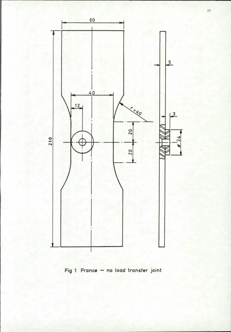
Two designs of no load transfer specimen were considered, both of which were tested in the FRFS programme, one design was from France and the other from Sweden. The French design was chosen for inclusion at the AGARD FRFS meeting in San Antonio and is shown in Fig 1. The most striking feature of the specimen is the offset fastener hole resulting in different stress gradients on either side of the hole. This represents the end fastener in a row where the stress gradient is asymmetric. The overall fastener load transfer is zero, though frictional load transfer may occur through the sideplate. The secondary bending is considered to be negligible. The specimen consists of a dogbone with a small non-load carrying element attached via the fastener. The small element and the dogbone undergo the same hole preparations and surface treatments, as described in section 3.5.
3.2 Low load transfer specimens
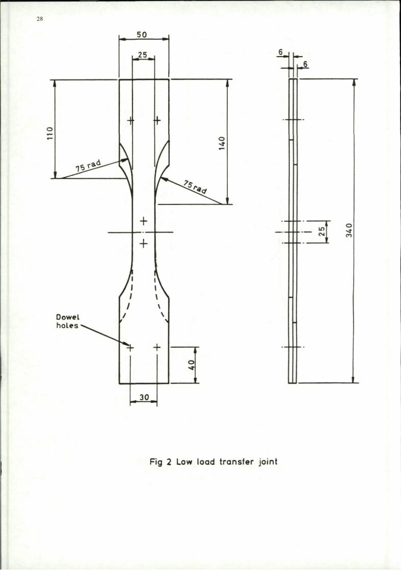
Two designs of low load transfer specimens were considered, both of which were tested in the FRFS programme. Both designs are reverse double dogbone specimens, one previously used by AGARD in the critically loaded hole technology programme and one developed in the UK. They are similar in concept and geometry, but the UK joint is significantly smaller. The UK joint (Fig 2) was selected for the following reasons.
1. Buckling problems associated with the AGARD joint — anti buckling guides may be necessary. These are undesirable in that if the bending is constrained, the LT and SB of the joint will be altered.
2. Cost.
3. Data was soon to be available on the UK joint using the same material, fastener systems, surface and hole preparations as the high load transfer joint.

Measurements of LT and SB on the AGARD joint were made in the FRFS programme(2). It was shown that each of the two fasteners transfer about 5% of the load. The secondary bending was measured and found to be in the range 0.1 to 0.25.
3.3 High load transfer specimens
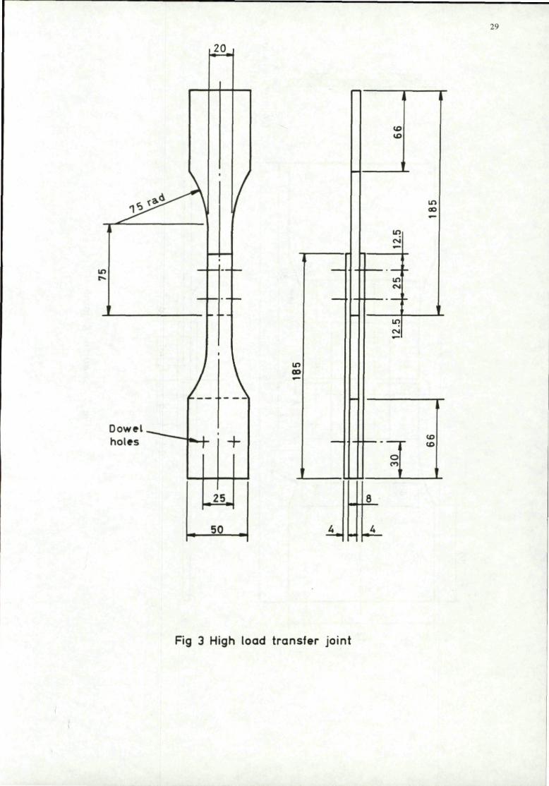
Eight different designs of double shear medium or high load transfer joints were tested in the FRFS programme, each joint containing between two and sixteen fasteners. Complex joints with multiple fastener rows and multiple fasteners in each row were rejected for the reasons described in section 2.1, namely that the important requirement for a standard joint is its ability to rate fastener systems and it was considered that a simple two fastener joint was adequate for this purpose. A load transfer of 30 — 50% in the test section is the main requirement. The selection was thus based on simplicity and cost. Test data on the UK joint, shown in Fig 3, was already available from the FRFS programme and it was selected for comparison with the no and low load transfer joints.
3.4 Specimen designs with high secondary bending
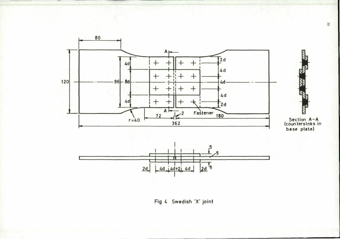
Four specimen designs were reviewed, though only three were considered for use as standard joints. The reason for including test data on the fourth is for comparison, since there is little data available on joints which meet the LT and SB requirements of this programme. The Swedish X' joint shown in Fig 4 is the joint which was considered unsuitable as a standard. The joint contains 16 fasteners and has very high lateral stress gradients both of which are undesirable features in a standard joint. It was used in the AGARD 'Fatigue Rated Fastener System' (FRFS) programme and the results presented here were obtained as part of that programme. Fig 5 shows the commonly used 11/2 dogbone specimen which was also tested as part of the FRFS programme by the Netherlands and USA. Fig 6 shows the UK Q-joint which is a modified version of the joint used in the FRFS programme having 1 /4" diameter fasteners in the controlling section. Fig 7 shows the detailed design of the Swedish U-joint which was not tested in the FRFS programme. This joint is a derivative of the X-joint used in the FRFS programme and was specifically designed for this investigation. It is essentially a single column X-joint but with a U-channel splice plale instead of the flat plate used in the X-joint construction. Two and four column U-joints have been used successfully in the past, but this is the first assessment of the single column variant.
3.5 Specimen requirements
Joints in Part 1 of the exercise were manufactured from a common batch of 7010 — T7651 material. Joints in Part 2 were manufactured from 7050 — T76 material from the same batch as that used in the FRFS programme. The chemical composition and mechanical properties of both materials are given in Table 2. Holes were produced by the general procedure:-pilot drill, drill, ream, cold-work, ream, deburr, measure hole diameter, countersink. Variations to this procedure for individual fastener systems are given in sections 4.1 to 4.4. All specimens were wet assembled using PR-1422 for Part 1 specimens and PR-1431-G for Part 2 specimens.
4. FASTENER SYSTEMS
In order to assess whether the joints described in the last section rate fastener systems in the same way, they must be tested with a range of fastener systems. Fatigue resistant fastener systems rely on one, or a combination of two or three mechanisms. These are clamping, interference fit and cold-working. The fastener systems chosen to assess the joints must therefore cover a range of combinations of these parameters which are typically used in practice. Accordingly four cases were chosen for each part of the exercise which cover this range. The four cases are described below and are based on the systems used in the FRFS programme. Systems 1A and 2A arc identical to FRFS-A and systems 1B and 2B are identical to FRFS-B. Systems 1C and 2C are similar to FRFS-C, which specified an interference fit of 90 ± 10 um.
Part 1 No or low secondary bending
1A
IB
COLD-WORKED
NO
FASTENER
HI-LOK
IC
ID
YES
NO
YES
HI-LOK
HI-TIGUE
HUCK-EXL
FIT
Clearance 20 ± 10 (im
Interference 25 ± 10 urn
Interference 110 ± 10um
Interference 120± lOfim
To check these fits, measurements of hole and fastener diameters were made for each joint and are summarised in Annex 1. The four fastener systems chosen for conditions 1A to ID were HI-LOK, HI-LOK in BOEING CX cold-worked hole, HI-TIGUE and HUCK EXL respectively.

Part 2 High secondary bending
COLD-WORKED FASTENER FIT
2A NO HI-LOK Clearance 20 ± 10 um
2B YES HI-LOK Interference 25 ± 10 mn
2C NO HI-TIGUE Interference 70 ± 10 tun
2D YES HI-TIGUE Interference 70 ± 10 urn
To check these fits, measurements of hole and fastener diameters were made for each joint and are summarised in Annex 1. The four fastener systems chosen for conditions 2 A to 2D were HI-LOK, HI-LOK in BOEING CX cold-worked hole, HI-TIGUE and HI-TIGUE in BOEING CX cold-worked hole.
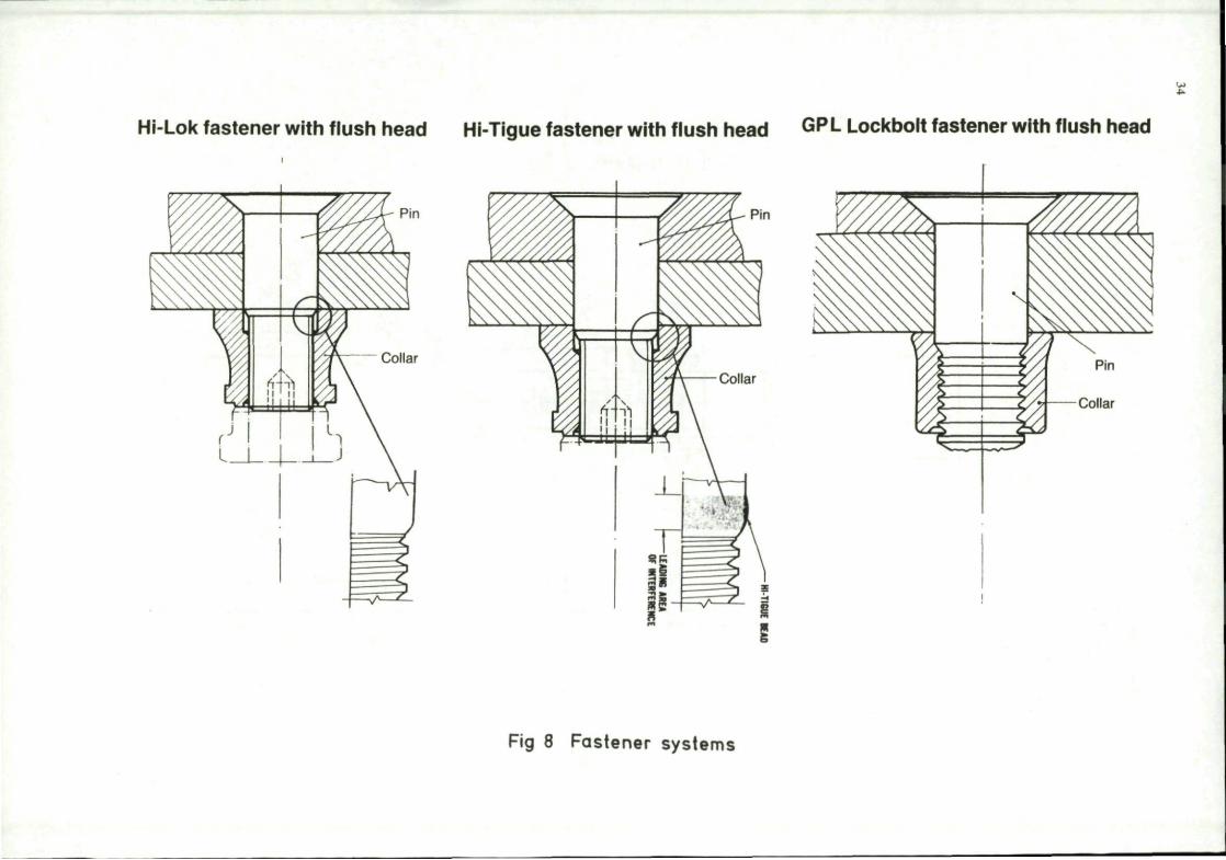
Details of each fastener system and hole preparations are described in sections 4.1 to 4.4. Sketches of the fastener systems are shown in Fig 8.
4.1 HI-LOK in plain hole (1A and 2A)
The HI-LOK fastener can be installed with light clearance or interference fits. It is available in steel and titanium with a variety of coatings. HI-LOKS used in this investigation were steel, 6.35mm dia. pins installed with a light clearance fit and assembled with shear-off type collars, or K-fast nuts. The pin and collar part numbers are given in Annex 2.
4.2 HI-LOK in cold-worked hole (1B and 2B).
The BOEING CX split sleeve process cold-expands the fastener holes prior to assembly. A mandrel is inserted through the fastener hole and a split sleeve passed over the mandrel, into the fastener hole. The mandrel is then pulled through the sleeve using a compressed air powered puller. The sleeve is discarded and the hole reamed to size. Specimens are then deburred and countersinks drilled. The HI-LOK fastener (as described in 4.1) is then installed with a light interference fit and assembled with a shear-off type collar, or K-fast nut.
The cold-working was carried out using F.T.I, standard tooling to the 8-0-N specification for Part 1 (the no or low secondary bending joints), and to the 6-3-N specification for Part 2 (the high secondary bending joints).
4.3 HI-TIGUE in plain hole (IC and 2C) and HI-TIGUE in cold-worked hole (2D)
The HI-TIGUE fastener is an interference fit fastener. The pin has conventional parallel sides of larger diameter than the hole, but has a small lubricated bead at the threaded end which expands the hole as it is assembled, allowing the parallel pin to be drawn through the hole, resulting in an interference fit. The pin must be drawn through the hole using a rivet gun and then the nut assembled and torque tightened to 10.2 — 11.3Nm.
The hole diameters required to give the fits described in section 4 are presented in Table 3. For the case of HI-TIGUE in cold-worked hole (2D), cold expansion was carried out using F.T.I, standard tooling to the 8-0-N speicfication using a common mandrel supplied by FOKKER (Q-joints and 1 1/2 dogbone only). A final reamer was also supplied by FOKKER to give the required fits in the Q-joints and 1 1/2 dogbone specimens. The pin and collar part numbers are given in Annex 2.
4.4 HUCKEXL(ID)
This fastener system combines all three fatigue life improvement mechanisms. It is a two part fastener pin, the first part cold working the hole as it is drawn through, the second part being a parallel sided pin which when installed produces an interference fit. A collar is placed over the interference fit pin and swaged into locking grooves, whilst the cold-working part is gripped and pulled until it separates from the installed pin. The complete operation is carried out using a special HUCK pulling tool.
The part numbers of the pins and collars are given in Annex 2. It should be noted that this fastener type was not available in the -6 length, consequently for the no load transfer specimen, the -8 length was used in conjunction with a thicker (7mm) washer.
5 TESTING PROGRAMMES
For both parts of the programme fatigue tests were carried out using the FALSTAFF loading sequence. Five fatigue tests per condition were performed at each of two stress levels. The details of the testing for Part 1 and Part 2 of the exercise are given in sections 5.1 and 5.2 respectively.
5.1 No or low secondary bending test programme
The fatigue tests were carried out at two sites; the no load transfer specimens were tested at CEAT, France, and the low and high load transfer specimens were tested at British Aerospace Woodford, UK. The specimen blanks were all manufactured by Cleveland Guest, UK and assembled at British Aerospace, Warton. The stress levels chosen were 280MPa and 350MPa on

the net section for the peak FALSTAFF level. The high load transfer specimens were tested at 280MPa and 375MPa, the life at 350MPa being calculated assuming a linear relationship between log stress and log life.
Tests were carried out using servo-hydraulic fatigue machines, these were:-
UK — Mayes lOOkN capacity.
France — CE AT 1 OOkN capacity.
Testing on the UK machines was carried out at a mean cyclic frequency of 11 Hz which gives a frequency of 1.8Hz for the maximum load excursion. Testing on the French machines was carried out at a mean cyclic frequency of 12Hz, giving a frequency of 2Hz for the maximum load excursion.
5.2 High secondary bending test programme
As described earlier, the information required from the test programme is twofold; the load transfer and secondary bending characteristics of the joints and the fatigue endurances. A number of specimens were strain gauged and measurements of LT and SB made using the procedures described in Annex 3.
The fatigue test stress levels varied from joint to joint, depending on the amount of secondary bending. The proposed two stress levels are defined as those levels which produced fatigue endurances of 5000 and 15000 FALSTAFF flights with the datum (clearance fit HI-LOK) fastener installed. These stress levels were not universally used in the programme. The net section and gross section stress levels for the peak applied FALSTAFF load used by each participant are given below:-
Net section Gross sectin
U K - Q joint 280MPa and 350 MPa 210MPa and 263MPa
NL/I-1 1/2 dogbone 268MPA and 335MPa 200MPa and 250 PMa
S-X joints 200MPa and 267MPa 150MPa and 200 MPa
S - U joint 276MPa and 345MPa 200MPa and 250 MPa
6 RESULTS AND DISCUSSIONS
The results and discussions of the two parts of the programme are presented in this section. The no or low secondary bending part of the exercise is discussed in section 6.1 and the high secondary bending part in section 6.2.
6.1 Results and discussions of the no or low secondary bending tests
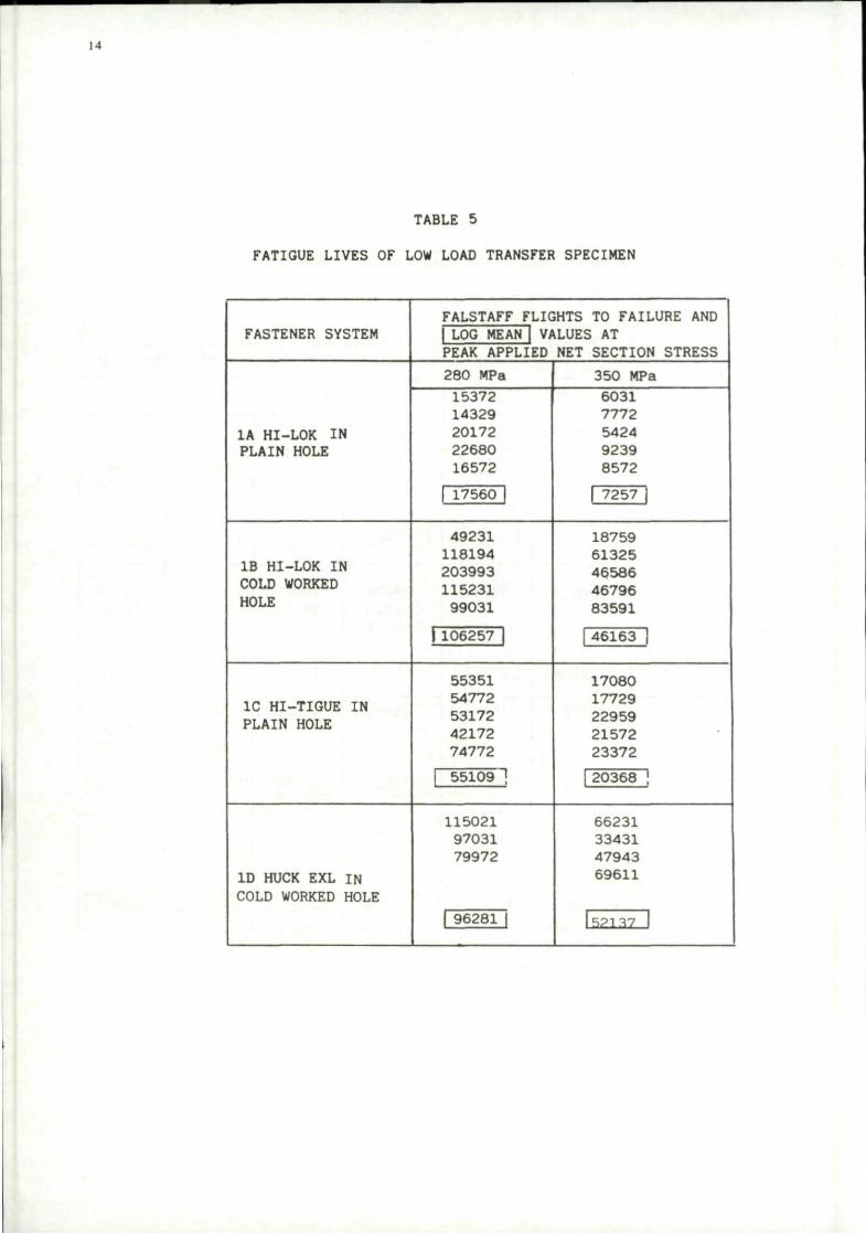
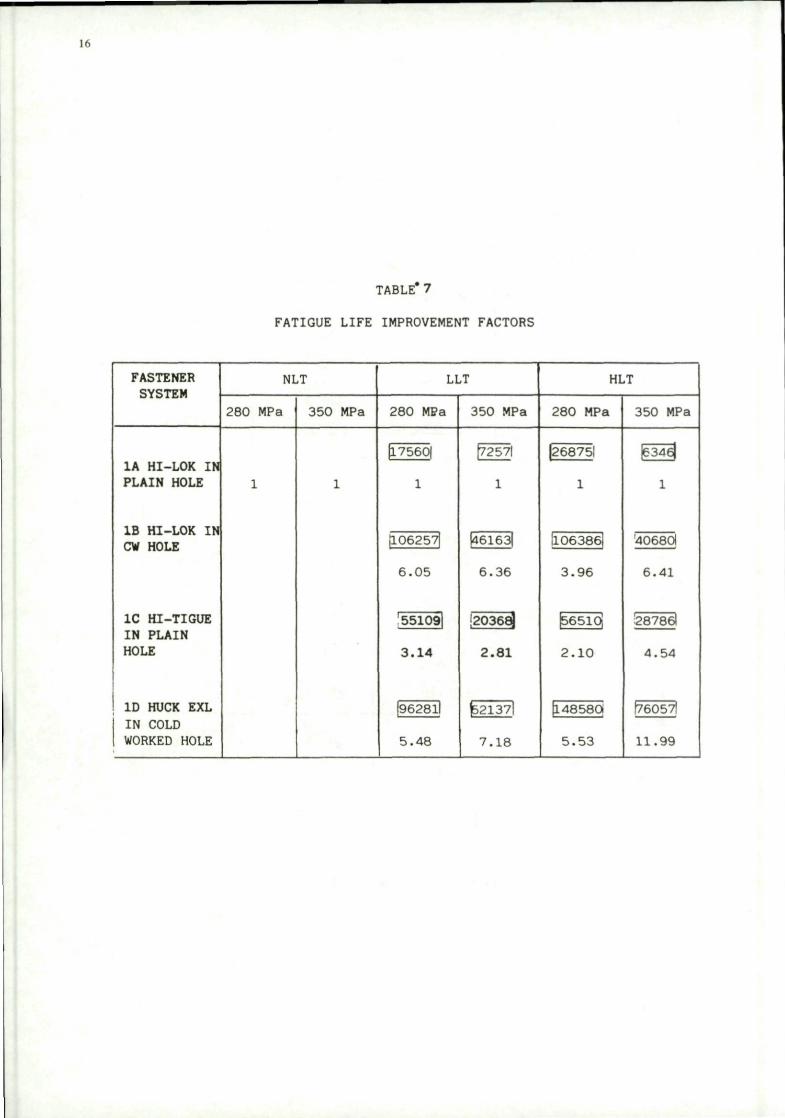
The fatigue test results from the no load, low load and high load transfer joints are given in Tables 4, 5 and 6 respectively. The relative life improvements over the datum system (HI-LOK fastener in a clearance fit hole) are given in Table 7. The life improvement factors are based on the log mean endurances for each test condition. In view of a number of problems involved with the testing of the no load transfer joint, these results are discussed separately. Section 6.1.1 discusses the results of the low and high load transfer joints, and section 6.1.2 the no load transfer joint.
6.1.1 Low and high load transfer joints
As discussed earlier in section 2.1, the joints have to be assessed in terms of life improvement factors. As can be seen from Table 7, all of the fastener systems are rated in a similar way by the two joints. The life improvement factors are consistently higher at the higher stress level, markedly so for the HUCK and HI-TIGUE fasteners. This is perhaps to be expected with interference fit fasteners, the magnitude of any beneficial compressive residual stress being controlled by the peak of the applied loading. This is not expected however for the case of cold-working, where more benefit is expected at lower stresses. The ranking of the fastener systems is consistent for the two joints considered and is summarised below:-
Life improvement ratios, based on log mean lives.
1 2 3 4 5 6 7 8 9 10 11 12
HI-LOK FASTENER SYSTEM i
r ' ' LLT FAST
HI •— ^ i
.1 HLT J HI-TIGUE
I I
n HI-LOK AND C. W.
I I I 1 HUCK EXL C. W.
I 1
The absolute fatigue lives of each joint are also very similar under the same test conditions. Log mean lives of each specimen type are within 35% of each other under identical test conditions. It was noted however subsequent to testing that the low load transfer joints had been assembled and tested with titanium fasteners instead of steel. The test data are plotted in Figs 9 and 10 for the low and high stress levels respectively. In view of the high scatter in the data, comparing the life improvement ratios on a log mean basis is not considered sufficient, as it may give a false impression of expected life improvements. The effect of scatter on life improvement ratios is therefore discussed in Annex 4. The effect of fastener type on fatigue crack origins must also be considered and detailed failure sites are given in Annex 5. General observations are also made on the effect of fastener type in the same annex.

6.1.2 No load transfer joints
The no load transfer joints showed scratches and surface dents received in transit from the UK to the testing laboratories in France. These damaged areas proved to be the initiation sites in over one third of the specimens. Of the remaining specimens, one half of the failures initiated in the test section and one half initiated in the dogbone radius. The fatigue test results are given in Table 4, from which a number of observations can be made. Failures from the dogbone radius are independent of the fastener system installed and hence the fatigue lives are also independent. Failures at the high stress level initiating from surface scratches produce fatigue lives lower than those failing from the dogbone radius. This is not the case at the lower stress level. In view of the fact that one third of the specimens failed from no apparent defect in the dogbone radius it must be concluded that this specimen is not suitable for fastener evaluation. The stress concentrating effect of the hole is readily overcome by fatigue resistant fastener systems. Fatigue failures therefore occur at an alternative site of stress concentration. A general conclusion can therefore be drawn, that a stress concentration greater than that of an open hole is required in a standard joint for fastener evaluation. The greater concentration can be simply achieved by using a joint in which some load is transferred by the fastener system. Other designs of no load transfer joint have been successfully used for fastener evaluation(2) but have not been tested with such extremes of interference fit and cold-working.
6.2 Results and discussion of the high secondary bending tests
A change in design of the UK Q-joint has meant that the test results have been obtained on two different designs of joint. An assessment of the importance of this change is made in Annex 6. The results of the LT and SB measurements on each joint are discussed in section 6.2.1. The fatigue test results are discussed in section 6.2.2.
6.2.1 Load transfer and secondary bending results
The results of the load transfer and secondary bending measurements on each of the joints are presented and assessed in this section. The results of the O-joint, 11/2 dogbone, U-joint and X-joint are presented in subsections a, b, c and d respectively. Both the LT and SB measurements vary to some degree with applied load. The values of SB at the peak applied load is important in determining if residual stresses are formed (or existing residual stress fields are modified) and if so their resulting magnitude around the fastener holes. This has a significant effect upon the damage done by the ensuing load cycles. Most fatigue damage however is done by the relatively lower load cycles, typically the maximum damage occurring at a stress range of about 1 /3 of the level 32 peak stress. The SB values at the damaging 1 /3rd peak stress level are also calculated as a % of the SB values at the peak load, i.e. if the SB value for a joint is 0.5 and the 1 /3rd ratio is 80% then the peak SB is 0.5 and the SB at l/3rd FALSTAFF peak load is 0.4.
a) O-joint measurements
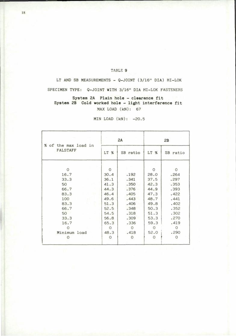
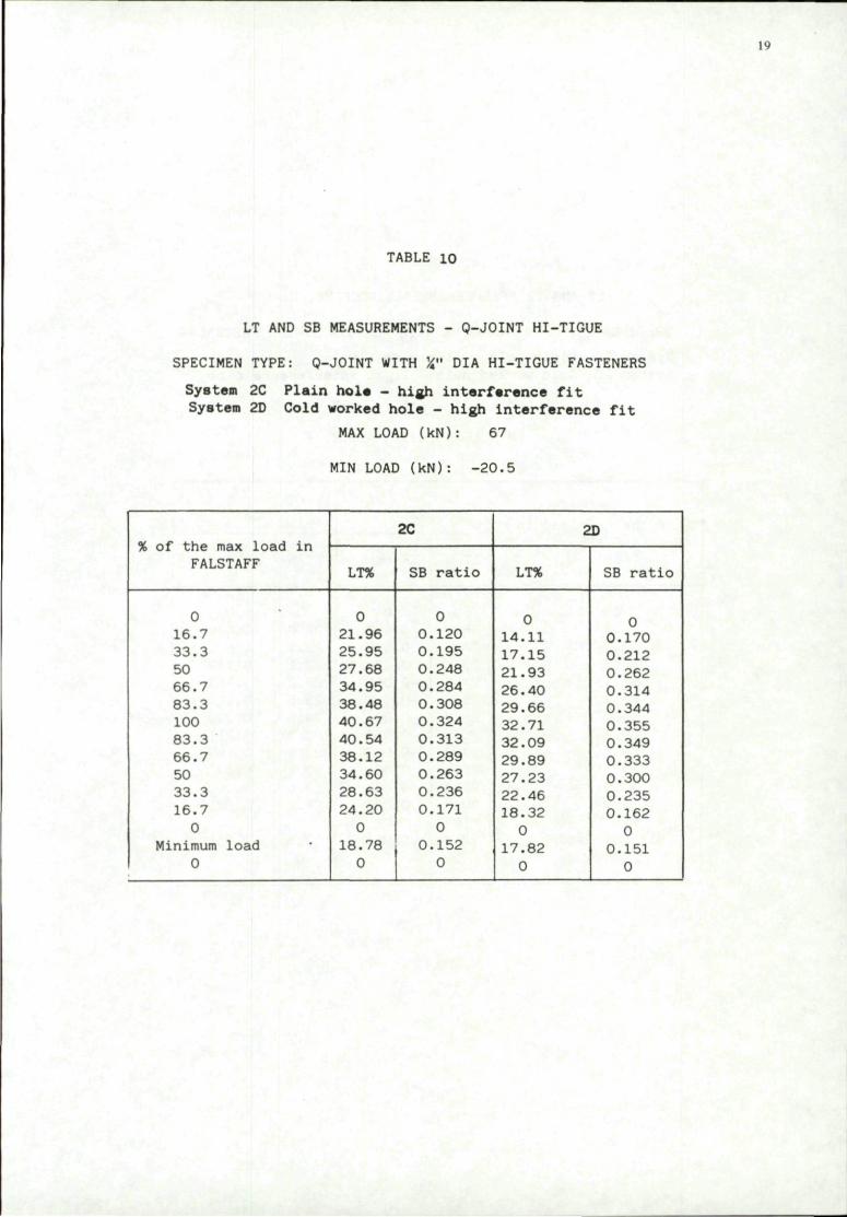
Measurements have been made on both variants of the O-joint (3/16" and 1/4" fasteners in the controlling section) with HTLOK fasteners installed in plain and cold worked holes. The results are presented in Tables 8 and 9 for the 1/4" and 3/16" fasteners respectively. Measurements of LT and SB with HI-TIGUE fasteners installed in plain and cold worked holes are presented in Table 10. A comparison of the results with different diameters of HI-LOK fasteners is made in Annex 6.
For each set of test data it is apparent that cold working does not significantly affect the SB ratio but does affect the LT. The effect of fastener fit however is quite marked. Comparing Tables 9 and 10, it can be seen that high interference fit fasteners (2C and 2D) produce lower LT and SB values in the test section than the light clearance/light interference fit fasteners (2 A and 2B). This variation in values however is quite small compared with other fastener-dominated joints (e.g. 1 1/2 dogbone) The O-joint is therefore classed as a fastener-dominated joint, but with a low fastener dominance. A summary of these measurements is presented in Fig 11.
The effect of applied load level on the LT and SB values is similar with any of the fastener systems installed, the 1 /3rd load ratio being between 63 — 73% for the four fastener systems.
b) 11/2 dogbone measurements
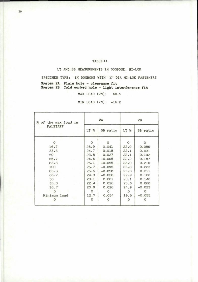
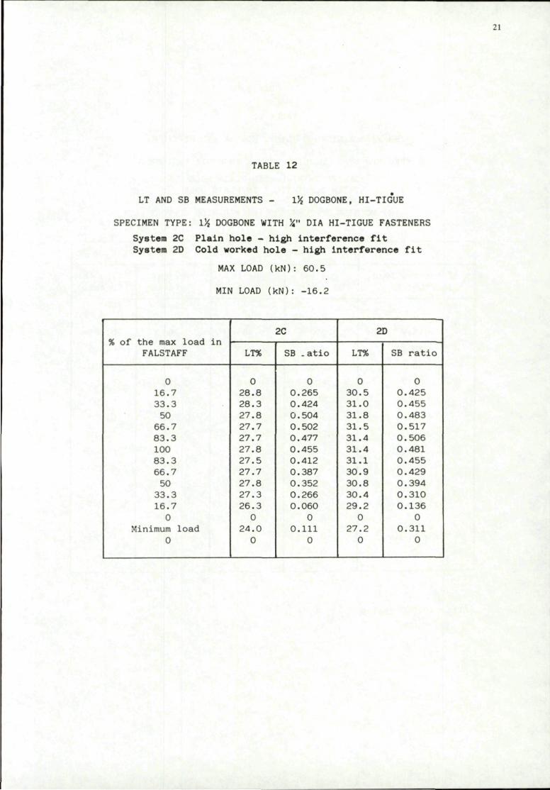
Measurements have been made on the 11/2 dogbone specimen with HI-LOK and HI-TIGUE fasteners installed in plain and cold worked holes. The results are presented in Tables 11 and 12 respectively. Values of load transfer vary little with either applied load or fastener fit. Load transfer values at peak applied load vary only from 24% to 31% for the four fastener systems, LT increasing with fastener interference. The secondary bending ratio however varies both with applied load and fastener fit. The variation of secondary bending with applied load shows a reversal of the bending direction with both the HI-LOK fastener installations (2A and 2B). In the HI-LOK in a plain hole case, the rate of change of SB ratio with applied load is quite extreme. With HI-TIGUE fasteners installed, however, very little variation of secondary bending with applied load is found, the l/3rd load ratio being about 80% for both plain and cold worked holes. Comparing the SB ratios for the four fastener installations shows a large dependence on the fastener system. The 11/2 dogbone specimen is therefore classified as a fastener dominated joint. A summary of the measurements at peak FALSTAFF load is presented in Fig 12.
c) U-joint measurements
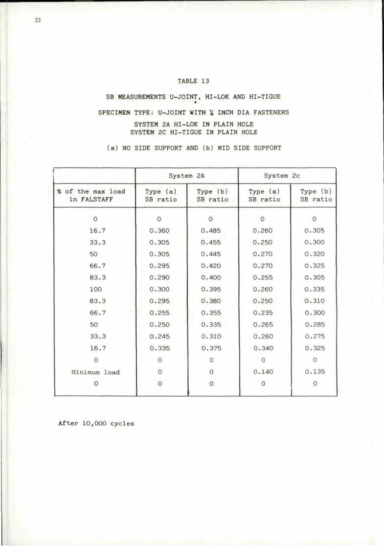
The results of secondary bending measurements on the U-joint with HI-LOK and HTTIGUE fasteners in plain holes are given in Table 13. Load transfer measurements were made on this specimen but evaluation of the results WEIS not realistic with so few strain gauges; the LT was assumed to be 50 — 55%. The SB measurements were made with and without mid-side supports. A considerable difference in SB values was observed when comparing the results with and without support. A peak value of 0.3 without support and 0.4 with support was measured with HI-LOK fasteners installed and 0.26 and 0.34 respectively with HI-TIGUE fasteners installed. SB values vary little with applied load, the l/3rd load ratio varying
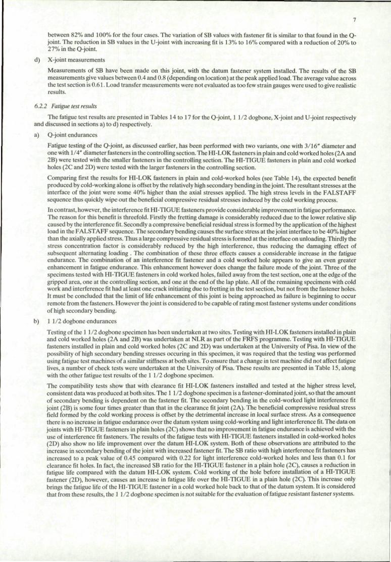
between 82% and 100% for the four cases. The variation of SB values with fastener fit is similar to that found in the Q-joint. The reduction in SB values in the U-joint with increasing fit is 13% to 16% compared with a reduction of 20% to 27% in the O-joint.
d) X-joint measurements
Measurements of SB have been made on this joint, with the datum fastener system installed. The results of the SB measurements give values between 0.4 and 0.8 (depending on location) at the peak applied load. The average value across the test section is 0.61. Load transfer measurements were not evaluated as too few strain gauges were used to give realistic results.
6.2.2 Fatigue test results
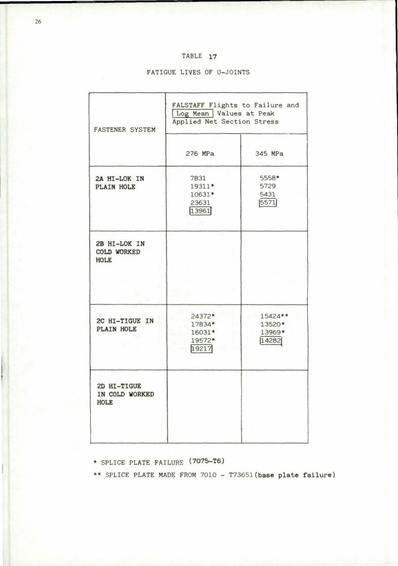
The fatigue test results are presented in Tables 14 to 17 for the O-joint, 1 1 /2 dogbone, X-joint and U-joint respectively and discussed in sections a) to d) respectively.
a) O-joint endurances
Fatigue testing of the Q-joint, as discussed earlier, has been performed with two variants, one with 3/16" diameter and one with 1/4" diameter fasteners in the controlling section. The HI-LOK fasteners in plain and cold worked holes (2A and 2B) were tested with the smaller fasteners in the controlling section. The HI-TIGUE fasteners in plain and cold worked holes (2C and 2D) were tested with the larger fasteners in the controlling section.
Comparing first the results for HI-LOK fasteners in plain and cold-worked holes (see Table 14), the expected benefit produced by cold-working alone is offset by the relatively high secondary bending in the joint. The resultant stresses at the interface of the joint were some 40% higher than the axial stresses applied. The high stress levels in the FALSTAFF sequence thus quickly wipe out the beneficial compressive residual stresses induced by the cold working process.
In contrast, however, the interference fit HI-TIGUE fasteners provide considerable improvement in fatigue performance. The reason for this benefit is threefold. Firstly the fretting damage is considerably reduced due to the lower relative slip caused by the interference fit. Secondly a compressive beneficial residual stress is formed by the application of the highest load in the FALSTAFF sequence. The secondary bending causes the surface stress at the joint interface to be 40% higher than the axially applied stress. Thus a large compressive residual stress is formed at the interface on unloading. Thirdly the stress concentration factor is considerably reduced by the high interference, thus reducing the damaging effect of subsequent alternating loading . The combination of these three effects causes a considerable increase in the fatigue endurance. The combination of an interference fit fastener and a cold worked hole appears to give an even greater enhancement in fatigue endurance. This enhancement however does change the failure mode of the joint. Three of the specimens tested with HI-TIGUE fasteners in cold worked holes, failed away from the test section, one at the edge of the gripped area, one at the controlling section, and one at the end of the lap plate. All of the remaining specimens with cold work and interference fit had at least one crack initiating due to fretting in the test section, but not from the fastener holes. It must be concluded that the limit of life enhancement of this joint is being approached as failure is beginning to occur remote from the fasteners. However the joint is considered to be capable of rating most fastener systems under conditions of high secondary bending.
b) 1 1/2 dogbone endurances
Testing of the 1 1 /2 dogbone specimen has been undertaken at two sites. Testing with HI-LOK fasteners installed in plain and cold worked holes (2 A and 2B) was undertaken at NLR as part of the FRFS programme. Testing with HI-TIGUE fasteners installed in plain and cold worked holes (2C and 2D) was undertaken at the University of Pisa. In view of the possibility of high secondary bending stresses occuring in this specimen, it was required that the testing was performed using fatigue test machines of a similar stiffness at both sites. To ensure that a change in test machine did not affect fatigue lives, a number of check tests were undertaken at the University of Pisa. These results are presented in Table 15, along with the other fatigue test results of the 1 1 /2 dogbone specimen.
The compatibility tests show that with clearance fit HI-LOK fasteners installed and tested at the higher stress level, consistent data was produced at both sites. The 1 111 dogbone specimen is a fastener-dominated joint, so that the amount of secondary bending is dependent on the fastener fit. The secondary bending in the cold-worked light interference fit joint (2B) is some four times greater than that in the clearance fit joint (2A). The beneficial compressive residual stress field formed by the cold working process is offset by the detrimental increase in local surface stress. As a consequence there is no increase in fatigue endurance over the datum system using cold-working and light interference fit. The data on joints with HI-TIGUE fasteners in plain holes (2C) shows that no improvement in fatigue endurance is achieved with the use of interference fit fasteners. The results of the fatigue tests with HI-TIGUE fasteners installed in cold-worked holes (2D) also show no life improvement over the datum HI-LOK system. Both of these observations are attributed to the increase in secondary bending of the joint with increased fastener fit. The SB ratio with high interference fit fasteners has increased to a peak value of 0.45 compared with 0.22 for light interference cold-worked holes and less than 0.1 for clearance fit holes. In fact, the increased SB ratio for the HI-TIGUE fastener in a plain hole (2C), causes a reduction in fatigue life compared with the datum HI-LOK system. Cold working of the hole before installation of a HI-TIGUE fastener (2D), however, causes an increase in fatigue life over the HI-TIGUE in a plain hole (2C). This increase only brings the fatigue life of the HI-TIGUE fastener in a cold worked hole back to that of the datum system. It is considered that from these results, the 1 1/2 dogbone specimen is not suitable for the evaluation of fatigue resistant fastener systems.

c) X-joint endurances
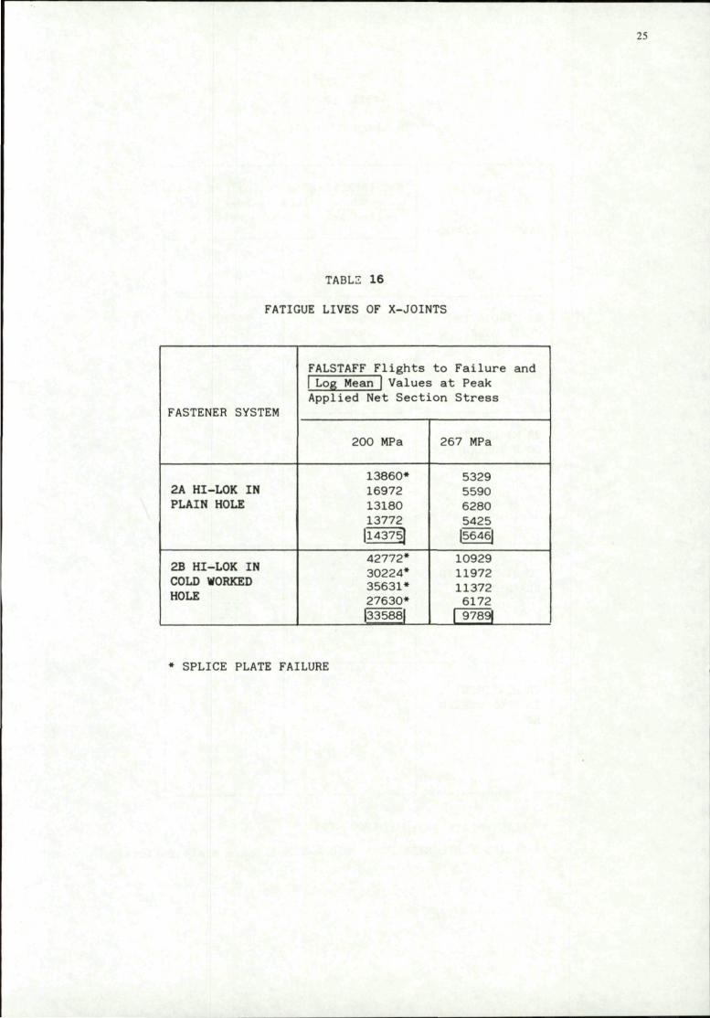
Fatigue testing of the X-joint was undertaken as part of the FRFS programme. The results obtained are presented in Table 16. The beneficial effect of cold working is clearly demonstrated in this joint, with life improvement factors of about two being obtained at both stress levels. It was noted however that cold worked specimens tested at the low stress level all failed in the splice plate; life improvement factors are therefore not relevant. Measurements of load transfer and secondary bending have not yet been made with both fastener systems installed. It is not possible therefore to assess the importance of these results. From the measurements on the datum system however it is surprising to find that cold working doubles the fatigue endurance despite the high value of secondary bending (0.6 with the datum system).
d) U-joint endurances
The fatigue test results of the U-joint specimen are presented in Table 17. Results were obtained at two stress levels with both the HI-LOK and HI-TIGUE fasteners installed in plain holes. Three failures with HI-LOK fasteners installed, occurred in the splice plate. All of the failures with HI-TIGUE fasteners installed, occurred in the splice plate. One non splice plate failure occurred with HI-TIGUE fasteners installed, but this was when the splice plate was of a different material (7010-T73651). All other splice plates were made from 7075-T6 material. It was decided to abort further testing of the U-joint specimen, on the assumption that most failures would occur in the splice plate. It was therefore concluded that the U-joint specimen was not a suitable design for fastener evaluation. It should be noted however that specimens with two or four U-channels fastened to the base plate have been used successfully in the past. A future development of the single column U-joint will probably involve thickening the U-channel web from 5 to 6mm.
7 CONCLUSIONS AND RECOMMENDATIONS OF PART 1, NO OR LOW SECONDARY BENDING
1) The low and high load transfer joints tested in this programme under FALSTAFF loading both produced similar fatigue lives under the same test conditions.
2) The ranking of all four fastener systems was the same in the low and high load transfer joints.
3) The low and high load transfer joints are considered equivalent in rating fatigue resistant fastener systems.
4) The no load transfer joint is not recommended as a standard joint for fastener evaluation.
8 CONCLUSIONS AND RECOMMENDATIONS OF PART 2, HIGH SECONDARY BENDING
This investigation has shown the difficulty in designing a joint for fastener evaluation which exhibits typical amounts of load transfer and secondary bending found in practice. All of the joints tested produced a number of failures originating away from the test section under certain conditions. Failure sites are detailed in Annex 5 and are summarised below.
Failure away from test section using fastener system
2A 2B 2C 2D
Q —joint •
1 1/2 — dogbone • •
X—joint • — —
U—joint • — • —
Clearly the U-joint would be rejected as not being able to rate the simpler fastener systems in the designated test section where the load transfer and secondary bending are being controlled. This was also the case for the X-joint. The 1 1/2 dogbone specimens exhibit a percentage of failures away from the test section with most fastener systems. The O-joint behaves similarly when high interference fit fasteners are installed. It is considered that these joints are therefore approaching their limits for assessing fatigue rated fastener system.
The 11/2 dogbone specimen has been shown to be a fastener-dominated joint in which the secondary bending in the test section is highly influenced by the fastener fit. The expected increase in fatigue life with an increasing degree of interference fit is offset by an increase in secondary bending ratio. In fact a slight reduction in fatigue life was obtained with high interference fit fasteners when compared to clearance fit fasteners. In a real structure it is anticipated that the secondary bending ratio at any location will to some degree be dependent on the fastener fit, but will be predominantly dependent on the local geometry. The 1 1/2 dogbone specimen is rejected as not being able to rate fastener systems in a useful way.
The Q-joint is the only specimen which consistently produces failures in the test section. The values of load transfer and secondary bending are predominantly governed by the geometry of the joint and to a lesser degree by the fastener fit. Of the joints considered in this exercise, the Q-joint is recommended as the most suitable for fastener evaluation purposes.
REFERENCES
3.
4.
T.COOMBE and R.B.URZI. Critically Loaded Hole Technology Pilot Collaborative Test Programme. Final Technical Report, AGARD Report No. 678, (November 1980)
H.H. van der LINDEN. Fatigue Rated Fastener Systems — An AGARD Coordinated Testing Programme. AGARD Report 721 (November 1985)
R.COOK and H.H. van der LINDEN. Standard Fatigue Test Specimens for Fastener Evaluation. Paper presented at AGARD meeting, SAN ANTONIO, (April 1985)
D.SCHUETZ and H.LOWAK. The effect of secondary bending on the fatigue strength of joints. RAE Library Translation No 1858,(1974)
10
TABLE 1
PARTICIPANTS IN THE STANDARD SPECIMENS PROGRAMME
Country
France
Italy
The Netherlands
Sweden
Sweden
United Kingdom
Participants
Centre D'essais Aeronautique de Toulouse - CEAT
University of Pisa
National Aerospace Laboratory -NLR
Saab-Scania
Flygtekniska Forsoksanstalten - FFA
Royal Aircraft Establishment
I P A Liberge
G Cavallini
H H van der Linden
L Jarfall
B Palmberg
R Cook
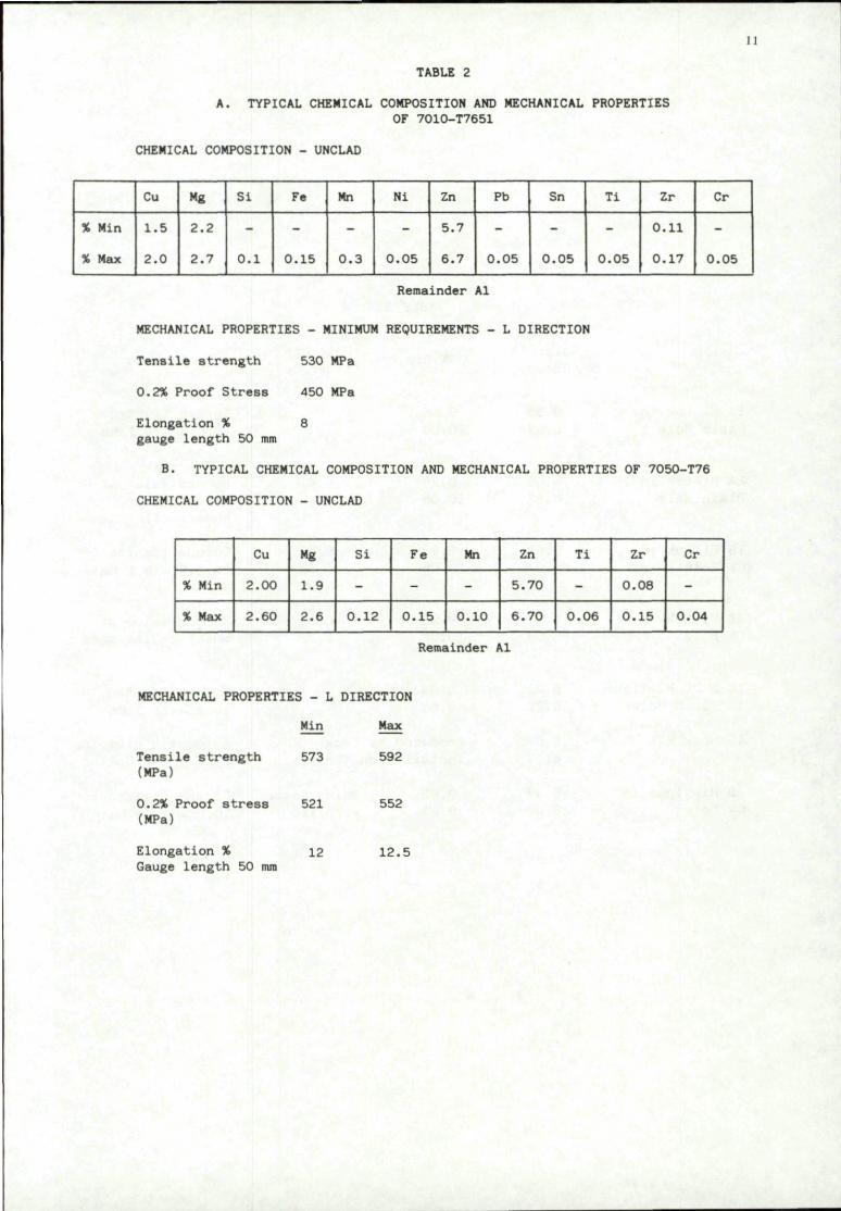
TABLE 2
A. TYPICAL CHEMICAL COMPOSITION AND MECHANICAL PROPERTIES OF 7010-T7651
CHEMICAL COMPOSITION - UNCLAD
11
% Min
% Max
Cu
1.5
2.0
Mg
2.2
2.7
Si
0.1
Fe
0.15
Mn
0.3
Nl
0.05
Zn
5.7
6.7
Remainder
Pb
0,05
Al
Sn
0.05
Ti
0.05
Zr
0.11
0.17
Cr
0.05
MECHANICAL PROPERTIES - MINIMUM REQUIREMENTS - L DIRECTION
Tensile strength 530 MPa
0.2% Proof Stress 450 MPa
Elongation % 8 gauge length 50 mm
B. TYPICAL CHEMICAL COMPOSITION AND MECHANICAL PROPERTIES OF 7050-T76
CHEMICAL COMPOSITION - UNCLAD
% Min
X Max
Cu
2.00
2.60
Mg
1.9
2.6
Si
-
0.12
Fe
-
0.15
Mn
-
0.10
Zn
5.70
6.70
Ti
-
0.06
Zr
0.08
0.15
Cr
-
0.04
Remainder Al
MECHANICAL PROPERTIES - L DIRECTION
Min Max
573 592 Tensile strength (MPa)
0.2% Proof stress (MPa)
Elongation % Gauge length 50 mm
521
12
552
12.5

12
1A Hi-Lok in Plain Hole
2A Hi-Lok in Plain Hole
IB Hi-Lok in CW Hole
2B Hi-Lok in CW Hole
IC & 2C Hi-Tigue in Plain Hole
ID Huck EXL
2D Hi-Tigue in CW Hole
Hole Dia (Remed)
6.35 6.37
6.35 6.37
5.97 6.04
5.71 5.79
6.21 6.25
6.045 6.17
5.97 6.04
TABLE 3
CSK Dia
• 9.96 10.06
9.96 10.06
9.96 10.06
9.96 10.06
9.83 9.93
Hole Dia (After CW)
-
-
6.30 6.32
6.30 6.32
-
Produced by Huck Installation Tools
9.83 9.93
Using Reamer supplied
Remarks
Torque tighten to 6.8 - 9.1 Nm
Record Value at which collar shears off
Torque tighten to 6.8 - 9.1 Nm
Record value at which collar shears off
Torque tighten to 10.2 - 11.3 Nm
Automatic clamping by Swaging Collar
Torque tighten to 10.2 - 11.3 Nra

13
TABLE 4
FATIGUE LIVES OF NO LOAD TRANSFER SPECIMENS
FASTENER SYSTEM
1A HI-LOK IN PLAIN HOLE
IB HI-LOK IN COLD WORKED HOLE
IC HI-TIGUE IN PLAIN HOLE
ID HUCK EXL IN COLD WORKED HOLE
INITIATION SITES AND FALSTAFF | LOG MEAN VALUES
TEST SECTION
280
77632 129281
1100182 1
32173
32173
62773 46330 88200
| 63538
350
22232 26173
24122 |
37973
37973 I
19432
119432 '
20240 22032 21730
21319 |
' 1 FLIGHTS . AT PEAK APPLIED NET £
SURFACE DEFECT
280
89525 112973 115773
105400
69232 94325 68831
76602 1
96360
96360
28373 61373
I 41729 1
350
23140
23140
16481 14126 17344
15924 |
18930
18930 '
19190
19190
•0 FAILURE AND .ECTION STRESS (MPa)
DOGBONE
280
63240
63240 |
87130 74232 65032 57530
| 70137 |
65646
65646 |
RADIUS
350
28081 23032
25431 |
38730 22360
I 29428 !
24222 29530 31200
28154 1
26631
| 26631
14
TABLE 5
FATIGUE LIVES OF LOW LOAD TRANSFER SPECIMEN
FASTENER SYSTEM
1A HI-LOK IN PLAIN HOLE
IB HI-LOK IN COLD WORKED HOLE
IC HI-TIGUE IN PLAIN HOLE
ID HUCK EXL IN COLD WORKED HOLE
FALSTAFF FLIGHTS TO FAILURE AND LOG MEAN VALUES AT PEAK APPLIED
280 MPa
15372 14329 20172 22680 16572
| 17560
49231 118194 203993 115231 99031
I 106257
55351 54772 53172 42172 74772
55109 !
115021 97031 79972
96281 |
NET SECTION STRESS
350 MPa 6031 7772 5424 9239 8572
| 7257
18759 61325 46586 46796 83591
46163 i
17080 17729 22959 21572 23372
20368 J
66231 33431 47943 69611
52132

15
TABLE 6
FATIGUE LIVES' OF HIGH LOAD TRANSFER SPECIMEN
FASTENER SYSTEM
1A HI-LOK IN PLAIN HOLE
IB HI-LOK IN COLD WORKED HOLE
IC HI-TIGUE IN PLAIN HOLE
ID HUCK EXL IN COLD WORKED HOLE
FALS'
PEAK
FAFF FLIGHTS TO FAILURE AND |LOG MEAN VALUES AT APPLIED NET SECTION STRESS
280 MPa
37898 23172 30839 3492_-14821
1 26875
51172 76759 224420 166196 93021
L06386 |
66624 32796 52172 123227 41024
56510
211711 155031 155172 96996 146572
148580 |
1
375 MPa
7572 4031 3559 3431 2959
1 4060 |
31759 34525 27772 27359
| 30212 !
34224 27749 27031 12972 20924
23368 !
87511 58880 55172 59929 52972
61814
350 MPa
6346 |
40680 I
28786
76057 |
Estimated figure assuming that a log-log S-N curve is linear in this region.
16
TABLE* 7
FATIGUE LIFE IMPROVEMENT FACTORS
FASTENER SYSTEM
1A HI-LOK IN PLAIN HOLE
IB HI-LOK IN CW HOLE
IC HI-TIGUE IN PLAIN HOLE
ID HUCK EXL IN COLD WORKED HOLE
NLT
280 MPa
1
350 MPa
1
LLT
280 MEa
H7560I
1
(106257
6.05
! 55109
3.14
962811
5.48
350 MPa
72571
1
46163]
6.36
J20368]
2.81
52137]
7.18
HLT
280 MPa
(268751
1
1106386
3.96
56510J
2.10
148580
5.53
350 MPa
6346)
1
406801
6.41
287861
4.54
[76057]
11.99

17
TABLE 8
LT AND SB MEASUREMENTS - Q- JOINT U" DIA) HI-LOK
SPECIMEN TYPE: O-JOINT WITH %" DIA HI-LOK FASTENERS
System 2A Plain hole - clearance fit System 2B Cold worked hole - light interference fit
MAX LOAD (kN): 67
MIN LOAD (kN): -20.5
% of the max load in FALSTAFF
0 16.7 33.3 50 66.7 83.3 100 83.3 66.7 50 33.3 16.7 0
Minimum load 0
LT %
0 22.3 28.3 32.3 35.2 36.2 37.6 38.9 40.0 40.5 39.6 39.3 0
21.9 0
2A
SB ratio
-------------
LT %
0 39.4 44.7 46.7 48.6 49.7 50.3 51.2 51.7 52.1 52.6 54.3 0
44.4 0
2B
SB ratio
0 .131 .321 .457 .495 .498 .494 .473 .450 .417 .341 .218 0
.236 0
18
TABLE 9
LT AND SB MEASUREMENTS - Q-JOINT (3/16" DIA) HI-LOK
SPECIMEN TYPE: O-JOINT WITH 3/16" DIA HI-LOK FASTENERS
System 2A Plain hole - clearance fit System 2B Cold worked hole - light interference fit
MAX LOAD (kN): 67
MIN LOAD (kN): -20.5
% of the max load in FALSTAFF
0 16.7 33.3 50 66.7 83,3 100 83.3 66.7 50 33.3 16.7
0 Minimum load
0
LT %
0 30.4 36.1 41.3 44.3 46.4 49.6 51.3 52.5 54.5 56.8 65.3
0 48.3
0
2A
SB ratio
.192
.341
.350
.376
.405
.443
.406
.348
.318
.309
.336 0
.418 0
LT %
0 28.0 37,5 42.3 44.9 47,3 48.7 49.8 50.3 51.3 53.3 59.3 0
52.0 0
2B
SB ratio
0 .264 .297 .353 .393 .422 .441 .402 .352 .302 .270 .419 0
.290 0
19
TABLE 10
LT AND SB MEASUREMENTS - Q-J0INT HI-TIGUE
SPECIMEN TYPE: O-JOINT WITH Jf" DIA HI-TIGUE FASTENERS
System 2C Plain hole - high interference fit System 2D Cold worked hole - high interference fit
MAX LOAD (kN): 67
MIN LOAD (kN): -20.5
% of the max load in FALSTAFF
0 16.7 33.3 50 66.7 83.3 100 83.3 66.7 50 33.3 16.7 0
Minimum load 0
LT%
0 21.96 25.95 27.68 34.95 38.48 40.67 40.54 38.12 34.60 28.63 24.20 0
18.78 0
2C
SB ratio
0 0.120 0.195 0.248 0.284 0.308 0.324 0.313 0.289 0.263 0.236 0.171
0 0.152
0
2D
LT%
0 14,11 17.15 21.93 26.40 29.66 32.71 32.09 29.89 27.23 22.46 18.32
0 17.82
0
SB ratio
0 0.170 0.212 0.262 0.314 0.344 0.355 0.349 0.333 0.300 0.235 0.162 0
0.151 0
20
TABLE 11
LT AND SB MEASUREMENTS 1% DOGBONE, HI-LOK
SPECIMEN TYPE: 1% DOGBONE WITH YA" DIA HI-LOK FASTENERS
System 2A Plain hole - clearance fit System 2B Cold worked hole - light interference fit
MAX LOAD (kN): 60.5
MIN LOAD (kN): -16.2
% of the max load in FALSTAFF
0 16.7 33.3 50 66.7 83.3 100 83.3 66.7 50 33.3 16.7 0
Minimum load 0
2A
LT %
0 25.9 24.7 23.8 24.6 25.1 25.7 25.5 24.3 23.1 22.4 20.9
0 12.7 0
SB ratio
0 0.041 0.018 0.027 -0.005 -0.055 -0.095 -0.058 -0.028 0.001 0.026 0.026
0 0.054
0
2B
LT %
0 22.0 22.1 22.1 22.2 23.0 23.8 23.3 22.9 23.1 23.6 24.9
0 19.5 0
SB ratio
0 -0.086 0.031 0.142 0.187 0.210 0.223 0.211 0.180 0.140 0.060
-0.023 0
-0.055 0
21
TABLE 12
LT AND SB MEASUREMENTS - 1% DOGBONE, HI-TIG*UE
SPECIMEN TYPE: 1V-, DOGBONE WITH JJ" DIA HI-TIGUE FASTENERS
System 2C Plain hole - high interference fit System 2D Cold worked hole - high interference fit
MAX LOAD (kN): 60.5
MIN LOAD (kN): -16.2
% of the max load in FALSTAFF
0 16.7 33.3 50
66.7 83.3 100 83.3 66.7 50
33,3 16.7 0
Minimum load 0
LT%
0 28.8 28.3 27,8 27.7 27.7 27.8 27.5 27.7 27.8 27.3 26.3 0
24.0 0
2C
SB _atio
0 0.265 0.424 0.504 0.502 0.477 0.455 0.412 0.387 0.352 0.266 0.060
0 0.111
0
2D
LT%
0 30.5 31.0 31.8 31.5 31.4 31.4 31.1 30.9 30.8 30.4 29.2 0
27.2 0
SB ratio
0 0.425 0.455 0.483 0.517 0.506 0.481 0.455 0.429 0.394 0.310 0.136
0 0.311
0
22
TABLE 13
SB MEASUREMENTS U-JOINT, HI-LOK AND HI-TIGUE •
SPECIMEN TYPE: U-JOINT WITH \ INCH DIA FASTENERS
SYSTEM 2A HI-LOK IN PLAIN HOLE SYSTEM 2C HI-TIGUE IN PLAIN HOLE
(a) NO SIDE SUPPORT AND (b) MID SIDE SUPPORT
1
% of the max load in FALSTAFF
0
16.7
33.3
50
66.7
83.3
100
83.3
66.7
50
33.3
16.7
0
Minimum load
0
System 2A
Type (a) SB ratio
0
0.360
0.305
0.305
0.295
0.290
0.300
0.295
0.255
0.250
0.245
0.335
0
0
0
Type (b) SB ratio
0
0.485
0.455
0.445
0.420
0.400
0.395
0.380
0.355
0.335
0.310
0.375
0
0
0
System
Type (a) SB ratio
0
0.260
0.250
0.270
0.270
0.255
0.260
0.250
0.235
0.265
0.260
0.340
0
0.140
0
2c
Type (b) SB ratio
0
0.305
0.300
0.320
0.325
0.305
0.335
0.310
0.300
0.285
0,275
0.325
0
0.135
0
1
After 10,000 cycles

23
TABLE 14
FATIGUE LIVES OF Q-JOINTS
Fastener System
2A HI-LOK IN PLAIN HOLE
2B HI-LOK IN COLD WORKED HOLE
2C HI-TIGUE IN PLAIN HOLE
2D HI-TIGUE IN COLD WORKED HOLE
FALSTAFF Flights ] Log Mean Value Applied Net Sect
| 280 MPa
12128 14431 12160 13831 14031 |l3280|
9631 12424 12329 16224 17631 |13337
18530 78032 25225 30860 |32572f
25573 77330 45632* 91225 111393* | 56504|
to Failure and s at Peak .ion Stress
350 MPa
3925 2929 3444 4336
|3639
3801 3172 3624 5323
|3905 |
21730 15825 13573 16385 11173* 8232 14448)
38981 32695 16840* 11159 7997
(18364}
* FAILURE AWAY FROM TEST SECTION -RESULT NOT INCLUDED IN LOG MEAN VALUE

24
TABLE 15
FATIGUE LIVES OF V/-. DOGBONE SPECIMENS
FASTENER SYSTEM
2A HI-LOK IN PLAIN HOLE
2B HI-LOK IN COLD WORKED HOLE
2C HI-TIGUE IN PLAIN HOLE
2D HI-TIGUE IN COLD WORKED HOLE
2D HI-LOK IN PLAIN HOLE COMPATIBILITY TESTS AT PISA
FALSTAFF Flights i to Failure and Log Mean Values at Peak
Applied Net Sect
268 MPa
18411 60372* 56972 63831 |44893|
29572 40431* 58231 35759* 39722J
30764 36572 |33542|
37146 42640* 38265* (392801
:ion Stress
335 MPa
9559 15419 23373 22231 ]16635|
13524* 14231 17962* 19172 16045]
9983 16734* 14062* 11780 |12899|
19007* 17308* 14946 14564* jl6358|
11165 13826 19955 (145501
•FAILURES INITIATING AWAY FROM TEST SECTION
25
TABLE 16
FATIGUE LIVES OF X-JOINTS
FASTENER SYSTEM
FALSTAFF Flights to Failure and I Log Mean | Values at Peak Applied Net Section Stress
200 MPa 267 MPa
2A HI-LOK IN PLAIN HOLE
13860* 16972 13180 13772 |14375(
5329 5590 6280 5425 |5646|
2B HI-LOK IN COLD WORKED HOLE
42772* 30224* 35631* 27630*
10929 11972 11372 6172
(33588 9789J
SPLICE PLATE FAILURE
26
TABLE 17
FATIGUE LIVES OF U-JOINTS
FASTENER SYSTEM
2A HI-LOK IN PLAIN HOLE
2B HI-LOK IN COLD WORKED HOLE
2C HI-TIGUE IN PLAIN HOLE
2D HI-TIGUE IN COLD WORKED HOLE
FALSTAFF Flights I Log Mean Values Applied Net Secti
276 MPa
7831 19311* 10631* 23631 |l396lf
24372* 17834* 16031* 19572* |19217|
to Failure and at Peak on Stress
345 MPa
5558* 5729 5431 5571|
15424** 13520* 13969* |14282
* SPLICE PLATE FAILURE (7075-T6)
•• SPLICE PLATE MADE FROM 7010 - T73651(base plate failure)
60
27
CM
i
o CM
O CV.
1
1
^
^ &
CN
Fig 1 France — no load transfer joint
2S
Dowel holes
+ +
h1
«*1 co
Fig 2 Low load transfer joint
29
to
Dowel holes
20
i n
in co
i n csi
in CM
IT)
o CO
CO CD
Fig 3 High load transfer joint
80
•mm
s
120 96
Ad
-66
Ad
r=A0
&
4- 4-h + ti
4- 4-
4 4- I
4- 4-
4- 4
1 + 4- 4-
72 eJtC 362
41
F2d
Ad
Ad
Ad
2d
Fastener 180 Section A-A
(countersinks in base plale)
1 1 £
i , ^
2dT| [ .Ad^Ad*^ Ad | [ jd t
Fig A Swedish 'X' joint

300
i n
j_r18
i n
185
Fig 5 I I dogbone specimen

32
L_._....„7
80
A / ]
u c>
i \
1
J
25
i
n
- j - - . -
/ "
o cn
J
i
'
i eeM
CM
C'sks controlling section
l V 1
. 4Q .
Fig 6 UK *Q' joint
-L_u_. e "='V-i
o CO
!
.C'sks / t M l
* / section
j \
M ' : F

1A8
3 . . .
3 j c
25
.Umim
38
60 12.5
27 „ 25
-n-
27
•/6.3
25 12.5
12.5
12.5
Fig 7 Swedish 'U' joint
L_f
Ul
Hi-Lok fastener with flush head Hi-Tigue fastener with flush head G P L Lockbolt fastener with flush head
Fig 8 Fastener systems

NLT
° LLT l
x HLT
O QD
X X X X X
•I + + + [ 2 - two resul ts
- log mean endurance
„ NLT __• cn P LLT x HLT
o NLT •o
I LLT Z » HLT
•o
8
NLT
| LLT x
HLT
o <|> o o o
x xic x
+ + +1 +
c /o o o
x |o< X
+ + I +
o o I 000 o
X jc X
4?
J L J L J L
10' 103
FALSTAFF f l ights
10°
Fig 9 Fatigue endurance at 280MPa net section stress

___: o
_ i J_
X
NLT
LLT
HLT (375)
NLT L.
j r LLT
~ HLT (375)
J NLT
- g l LLT I o
I * HLT 5 (375) o o
NLT -
° LLT 3 I
HLT (375)
10'
-
-
—
-
-
_
-
-
-
-
X X
+ 4+ |f
2 - two results
1 - l og mean endurance _ _
i I I I I
| x x x
+
I I I I
ocf
CD (|
XK jxxx
+ 1
o oo i
X
ooop
i
oo
oo
+2 +
CD
+2(f +
o
X
ef X
X | XX
+ +-H-)
1 1 1
X
+
1 , 1
10 FALSTAFF flights
Fig 10 Fatigue endurances at 350MPa net section stress
10'

o
19 •XI
a. m-*
•*-in c f-8
m o
50
-a n o
-_£ (TJ
<u a . ro
cr c •5 c _a
m • a c o u
in
40 - . 5
30 - .4
20 - .3
10 - .2
0 L .1
37
- 20
-16
-12
£ •
_±
<u c -J
I/. (0 _
80-
60
A0
20
20
0
X
_c
4. O C ra w _3
TJ C 4* I f D
_r
2A Hi-Lok in plain hole
2B Hi-Lok in
cold worked hole
2C Hi-Tigue in plain hole
2D Hi-Tigue in
cold worked hole
Fastener system
Fig 11 Summary of Q—joint data at 350MPa peak stress

38
0L- .2 2A
Hi-Lok in plain hole
2B Hi-Lok in
cold worked hole
2C Hi-Tigue in plain hole
2D Hi-Tigue In
cold worked hole
Fastener system
Fig 12 Summary of ITdogbone data at 335MPa peak stress
39
ANNEX 1
FASTENER FITS
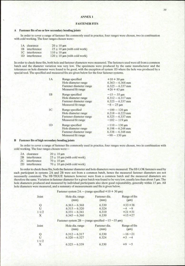
A Fastener fits of no or low secondary bending joints
In order to cover a range of fastener fits commonly used in practice, four ranges were chosen, two in combination with cold working. The four ranges chosen were:-
1A clearance IB interference IC interference 1D interference
2 0 ± lOum 25 ± 10 (im (with cold work)
110± 10(im 120 ± 10 (im (with cold work)
In order to check these fits, both hole and fastener diameters were measured. The fasteners used were all from a common batch and the diameter variation was very low. The specimens were produced by the same manufacturer and the tolerances on hole diameter were found to be good, with the exception of system 1D where the hole was produced by a special tool. The specified and measured fits are given below for the four fastener systems.
1A Range specified Hole diameter range Fastener diameter range Measured fit range
1B Range specified Hole diameter range Fastener diameter range Measured fit range
IC Range specified Hole diameter range Fastener diameter range Measured fit range
ID Range specified Hole diameter range Fastener diameter range Measured fit range
+10 + 30um 6 . 3 6 3 - 6 . 3 6 8 mm 6.325 — 6.337 mm +26 + 43 urn
— 15 — 35 um 6 . 3 1 2 - 6 . 3 1 7 mm 6 . 3 2 5 - 6 . 3 3 7 mm - 8 - 25 (im
- 1 0 0 - 1 2 0 urn 6 . 2 1 8 - 6 . 2 2 3 mm 6 . 3 2 5 - 6 . 3 3 7 mm - 1 0 2 - 1 1 9 urn
- 1 1 0 - 1 3 0 jim 6 . 1 9 8 - 6 . 2 4 8 mm 6 . 3 3 8 - 6 . 3 4 8 mm - 9 0 - 1 5 0 jim
B Fastener fits of high secondary bending joints
In order to cover a range of fastener fits commonly used in practice, four ranges were chosen, two in combination with cold working. The four ranges chosen were:—
2A clearance 2B interference 2C interference 2D interference
20 ± 10 ism 25 ± 10 jim (with cold work) 7 0 ± lOum 70 ± 10 jim (with cold work)
In order to check these fits, both the fastener diameter and hole diameters were measured. The HI-LOK fasteners used by each participant in systems 2A and 2B were not from a common batch, hence the measured fastener diameters are not necessarily consistent. The HI-TIGUE fasteners however were from a common batch and the measured diameters are therefore the same. Variation in fastener diameter for a given batch was found to be very low, usually less than about 5 um. The hole diameters produced and measured by individual participants also show good repeatability, generally within 15 um. All hole diameters were measured, and a summary of measurements and fits is given below.
Joint
Fastener system 2A — (range specified +10 + 30 <im)
Hole dia. range Fastener dia. Range of fits
Q U
1 1/2 X
(mm)
6.363-6.368 6.315-6.320 6.331-6.341 6.345-6.360
(mm)
6.330 6.324 6.310 6.330
(Urn)
+33+38 - 4 - 9 +21+31 +15+27
Joint
Fastener system 2B — (range specified — 15 —35 um)
Hole dia. range Fastener dia. Range of fits
Q
u 1 1/2
X
(mm)
6.312-6.317 6.320-6.327
6.325-6.339
(mm)
6.330 6.324
6.330
(Urn)
- 1 6 - 2 1 +3 - 4
+9 - 5

40
Q 1 1/2
U
Q 1 1/2
U
Fastener system 2C — (range specified —60 —80 um)
6.246-6.258 6.325 -67 -79
6.225-6.250 6.325 - 7 5 - 1 0 0
Fastener system 2D (range specified —60 —80 (im)
6.246-6.257 6.325 - 6 8 - 7 9
6.220-6.235 6.325 - 9 0 - 1 0 5 *Holes produced by the same reamer
41
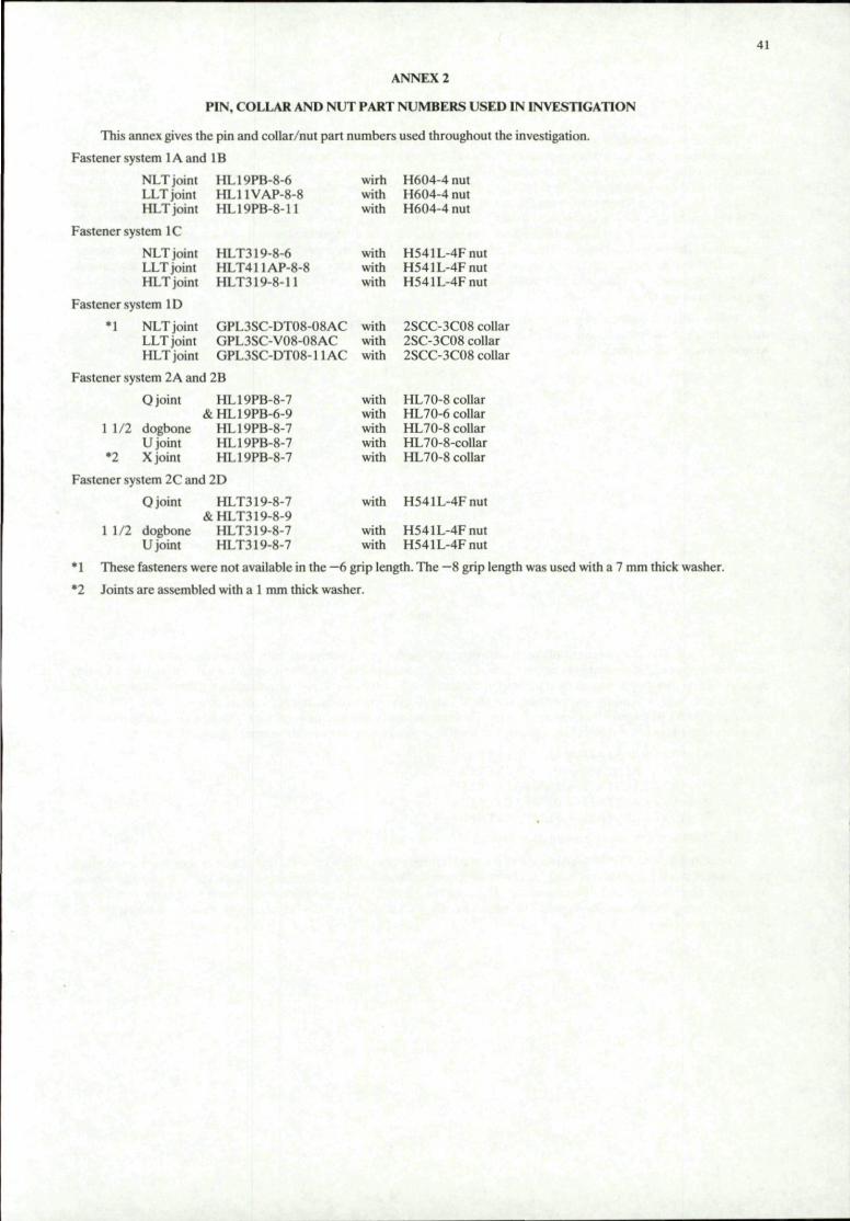
ANNEX 2
PIN, COLLAR AND NUT PART NUMBERS USED IN INVESTIGATION
This annex gives the pin and collar/nut part numbers used throughout the investigation.
Fastener system lAand IB
NLT joint LLT joint HLT joint
Fastener system IC
NLT joint LLT joint HLT joint
Fastener system ID
HL19PB-8-6 HL11VAP-8-8 HL19PB-8-11
HLT319-8-6 HLT411AP-8-8 HLT319-8-11
M NLT joint LLT joint HLT joint
GPL3SC-DT08-08AC GPL3SC-V08-08AC GPL3SC-DT08-11AC
Fastener system 2A and 2B
1 1/2
O joint
dogbone U joint X joint
HL19PB-8 &HL19PB-6
HL19PB-8 HL19PB-8 HL19PB-8
Fastener system 2C and 2D
0 joint HLT319-8 7 &HLT319-8-9
1 1/2 dogbone HLT319-8-7 U joint HLT319-8-7
1 These fasteners were not available in the
wirh H604-4 nut with H604-4 nut with H604-4 nut
with H541L-4Fnut with H541L-4Fnut with H541L-4Fnut
with 2SCC-3C08 collar with 2SC-3C08 collar with 2SCC-3C08 collar
with HL70-8 collar with HL70-6 collar with HL70-8 collar with HL70-8-collar with HL70-8 collar
with H541L-4Fnut
with with
H541L-4Fnut H541L-4Fnut
-6 grip length. The •
*2 Joints are assembled with a 1 mm thick washer.
-8 grip length was used with a 7 mm thick washer.
42
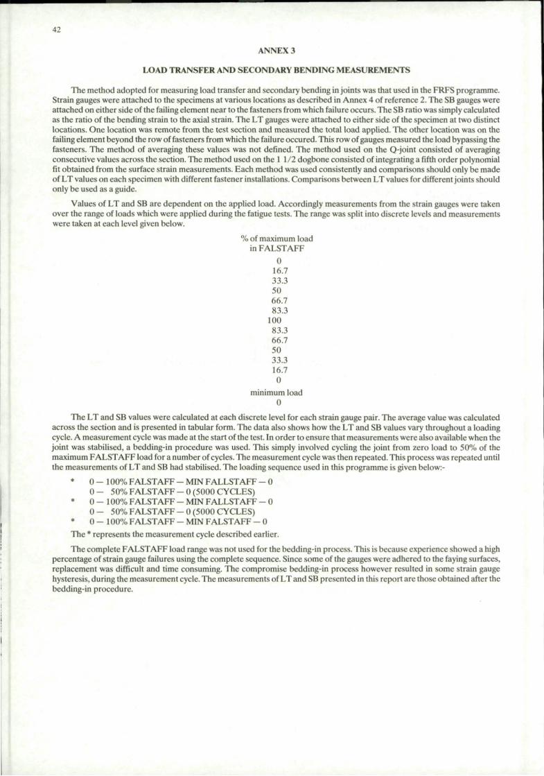
ANNEX 3
LOAD TRANSFER AND SECONDARY BENDING MEASUREMENTS
The method adopted for measuring load transfer and secondary bending in joints was that used in the FRFS programme. Strain gauges were attached to the specimens at various locations as described in Annex 4 of reference 2. The SB gauges were attached on either side of the failing element near to the fasteners from which failure occurs. The SB ratio was simply calculated as the ratio of the bending strain to the axial strain. The LT gauges were attached to either side of the specimen at two distinct locations. One location was remote from the test section and measured the total load applied. The other location was on the failing element beyond the row of fasteners from which the failure occured. This row of gauges measured the load bypassing the fasteners. The method of averaging these values was not defined. The method used on the Q-joint consisted of averaging consecutive values across the section. The method used on the 1 1/2 dogbone consisted of integrating a fifth order polynomial fit obtained from the surface strain measurements. Each method was used consistently and comparisons should only be made of LT values on each specimen with different fastener installations. Comparisons between LT values for different joints should only be used as a guide.
Values of LT and SB are dependent on the applied load. Accordingly measurements from the strain gauges were taken over the range of loads which were applied during the fatigue tests. The range was split into discrete levels and measurements were taken at each level given below.
% of maximum load in FALSTAFF
0 16.7 33.3 50 66.7 83.3
100 83.3 66.7 50 33.3 16.7 0
minimum load 0
The LT and SB values were calculated at each discrete level for each strain gauge pair. The average value was calculated across the section and is presented in tabular form. The data also shows how the LT and SB values vary throughout a loading cycle. A measurement cycle was made at the start of the test. In order to ensure that measurements were also available when the joint was stabilised, a bcdding-in procedure was used. This simply involved cycling the joint from zero load to 50% of the maximum FALSTAFF load for a number of cycles. The measurement cycle was then repeated. This process was repeated until the measurements of LT and SB had stabilised. The loading sequence used in this programme is given below:-
* 0 - 1 0 0 % FALSTAFF - MIN FALLSTAFF - 0 0 - 50% FALSTAFF - 0 (5000 CYCLES)
* 0 - 1 0 0 % FALSTAFF - MIN FALLSTAFF - 0 0 - 50% FALSTAFF-0(5000 CYCLES)
* 0 - 1 0 0 % FALSTAFF - MIN FALSTAFF - 0 The * represents the measurement cycle described earlier.
The complete FALSTAFF load range was not used for the bedding-in process. This is because experience showed a high percentage of strain gauge failures using the complete sequence. Since some of the gauges were adhered to the faying surfaces, replacement was difficult and time consuming. The compromise bedding-in process however resulted in some strain gauge hysteresis, during the measurement cycle. The measurements of LT and SB presented in this report are those obtained after the bedding-in procedure.

43
ANNEX 4
IMPORTANCE OF SCATTER
The fatigue endurances for the no or low secondary bending programme are presented in figures 9 and 10 for the case of low and high applied stresses respectively. The scatter is generally lower at the higher stress level but not significantly. There appears to be no relationship between fastener system and the amount of scatter. The NLT transfer specimen endurances are similar with all of the fastener systems and at both stress levels and are therefore not further considered in this Annex.
The fatigue life scatter bands of the three enhanced fastener systems (1B, 1C and 1D) overlap for both joints at both stress levels. It should be borne in mind that the HLT joint endurances were obtained at 375MPa and the LLT joint at 350MPa. Scatter bands of the datum fastener system only overlap those of the other three systems in one case. This is the case of the HLT joint at the lower stress level with HI-TIGUE fasteners. This could potentially result in a lower than unity life improvement with HI-TIGUE fasteners over the datum system.
To quantify the effects of scatter on fatigue life improvement factors (LIF), the results are analysed in two ways. Firstly the extremes of LIF are calculated from the data. Secondly each data set is considered to be distributed in some regular way. The minimum lives of each data set are used to calculate LIF (min) and the maximum lives of each data set to calculate LIF (max). Assuming the distribution of each data set to be log normal, the log mean values are also used to calculate a factor LIF (Av).
TABLE A1 Absolute Life Improvement Factors
, , - . „ . . . _ !
I FASTENER LLT JOINT SYSTEM 280MPa 350MPa
I HI-TIGUE ! 1 .86 - 5-22
I HI-LOK IN | 2.17 - 14-24 I C.W. HOLE
I HUCK EXL IN | 3-53 - 8 .03 I C.W. HOLE
i
1.85 - 4-31
2.03 - 15.41
3-62 - 12.83
HLT JOINT 280MPa 375MPa
0.86 - 8.31 1.71 - 11-57 i
1.35 - 15-14 | 3-61 - 11.67 !
2.56 - 14.28 | 7.00 - 29-57 I
1 1
TABLE A2 Distributed Life Improvement Factors
1 • 1 1 1 1
FASTENER LLT JOINT HLT JOINT SYSTEM LIF | 280 350 280 375
MIN | 2-94 3.15 2.21 4-38 I HI-TIGUE AV 3-14 2.81 2.10 | 4-54
MAX 3-30 I 2.53 I 3-25 4.52
1 HI-LOK MIN 3-44 3-46 1 3-45 9-25 IN C.W. AV 6.05 6.36 3-96 6.41
! HOLE MAX 8.99 9.05 5.92 I 4-56
MIN j 5-58 | 6.16 6.54 17-90 | | HUCK EXL IN I AV 5-48 | 7-18 | 5-53 11-99 | C.W. HOLE MAX 5-07 7-53 ! 5-59 | 11-56 i I I I I I I
From these two tables it can be seen that there are no systematic differences in the way in which the two types of joint rate the fastener systems. It does however indicate that the life improvement factor based on the log mean values (Table A2) of the endurance data provide a good guide to the improvements found in practice. If worst case data is required for minimum life improvement estimations, then the absolute approach (Table Al) must be used.

45
ANNEX 5
PRIMARY FATIGUE CRACK ORIGINS
Primary fatigue crack origins have been noted by each participant on each fatigue test specimen and are presented in this annex.
a) HLT Specimen
s~y
^ 12
6~-_T A
> a <i
r—W
} " (
N, d
^ 12
Fastener 1
Fastener 2
1 1
I FASTENER SYSTEM i
i i i i
i
i i
i
1A. i
i i
HI-LOK IN PLAIN HOLE
Maximum St
1
net r e s s (MPa)
280 280 280 280 280
375 375 375 375 375
SPEC NO
HI/1 H1/6 H1/5 HI/10 H1/7
H1/2 HI/9 H1/8 H1/3 H1/4
F l i g h t s to F a i l u r e
37898 23172 30839 34929 14821
7572 4031 3559 3431 2959
ORIGINS |
4 10 a c 10
a a a a
5 ,6 ,7 ,111 i
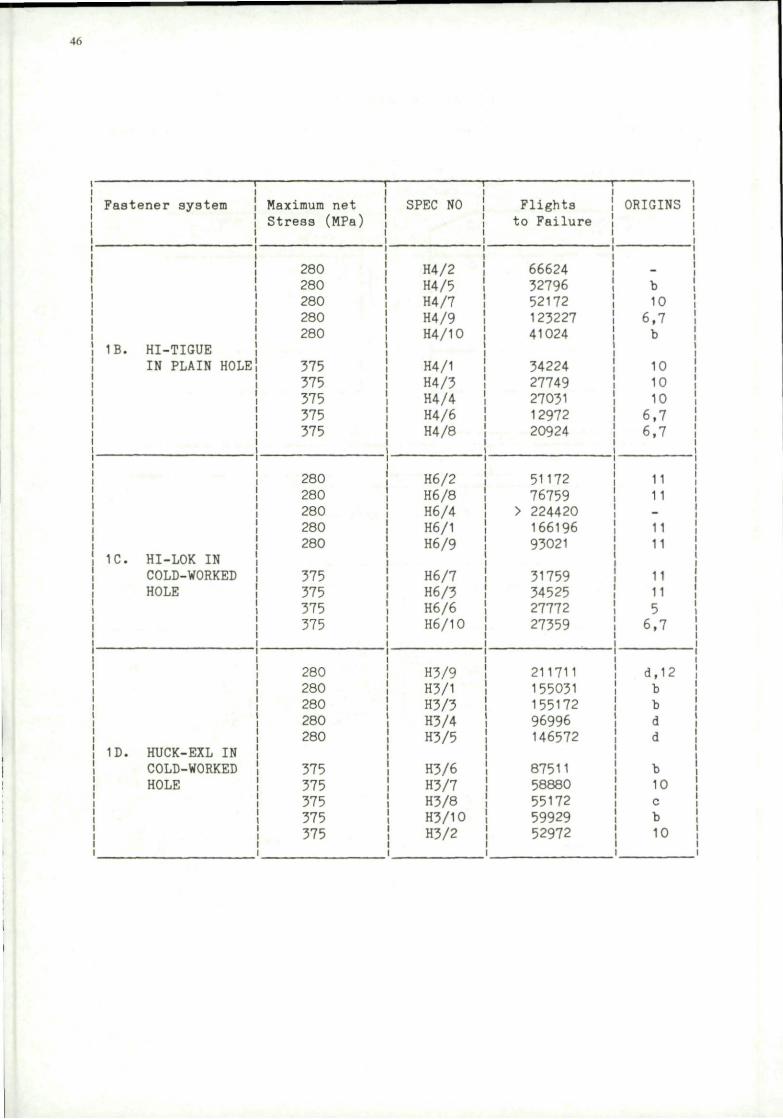
46
1 1
Fastener system
1B. HI-TIGUE IN PLAIN HOLE
1C. HI-LOK IN COLD-WORKED HOLE
1D. HUCK-EXL IN COLD-WORKED HOLE
i
i i
i i
Maximum net Stress (MPa)
280 280 280 280 280
375 375 375 375 375
280 280 280 280 280
375 375 375 375
280 280 280 280 280
375 375 375 375 375
SPEC NO
H4/2 H4/5 H4/7 H4/9 H4/10
H4/1 H4/3 H4/4 H4/6 H4/8
H6/2 H6/8 H6/4 H6/1 H6/9
H6/7 H6/3 H6/6 H6/10
H3/9 H3/1 H3/3 H3/4 H3/5
H3/6 H3/7 H3/8 H3/10 H3/2
Flights to Failure
66624 32796 52172 123227 41024
34224 27749 27031 12972 20924
51172 76759
> 224420 166196 93021
31759 34525 27772 27359
211711 155031 155172 96996 146572
87511 58880 55172 59929 52972
i
ORIGINS
1 b 10 6,7 b
10 10 10 6,7 6,7
11 11 -
11 11
11 11 5 6,7
d,12 b b d d
b 10 c b 10

Summary of HLT-joints
47
|Fastener I TOP PLATE (CSK) System 1 280 375
(1) 37898 ! (4) 2959
u i
37,898 2,958
(9) 1232271 (6) 12972 IB (8) 20924
123,227 16,475
(6) 27772 IC (10) 27359
27,565
i 1D i 1
i i i
EOT PLATE CENTRE PLATE 280 375 280 375
(6) 23172 I (5) 30839 (2) 7572j (7) 14821 (10) 34929 | (9) 4031 I
(8) 3559) (3) 3431 j
18,532 32,820 4,394
(7) 52172 I (1) 34224| (5) 32796 (3) 27749! (10) 41024 ! (4) 27031!
i i i i i • i
I I I I 52,172 28,396 36,680
i i ' i i
(2) 51172 i (7) 31759! (8) 76759 I (3) 34525! (1) 166196! (9) 93021
88,276 33,113
(9) 2117111 (7) 588801 (9) 211711 (6) (2) 52972! (1) 155031 (8)
(3) 155172 I (10) (4) 96996 (5) 146572
211,711 55,848 1 148,579 66,1411
( ) Specimen numbers
Observations
(1) Failures in the top and bottom plates originate at fastener 1.
(2) Failures in the centre plate originate at fastener 2.
(3) The majority of failures using system 1D are in the centre plate, the longest lives are achieved with this system.
(4) All of the failures using system 1C are in the side plates, the majority in the bottom plate.
(5) The majority of failures using system 1B are in the side plates.
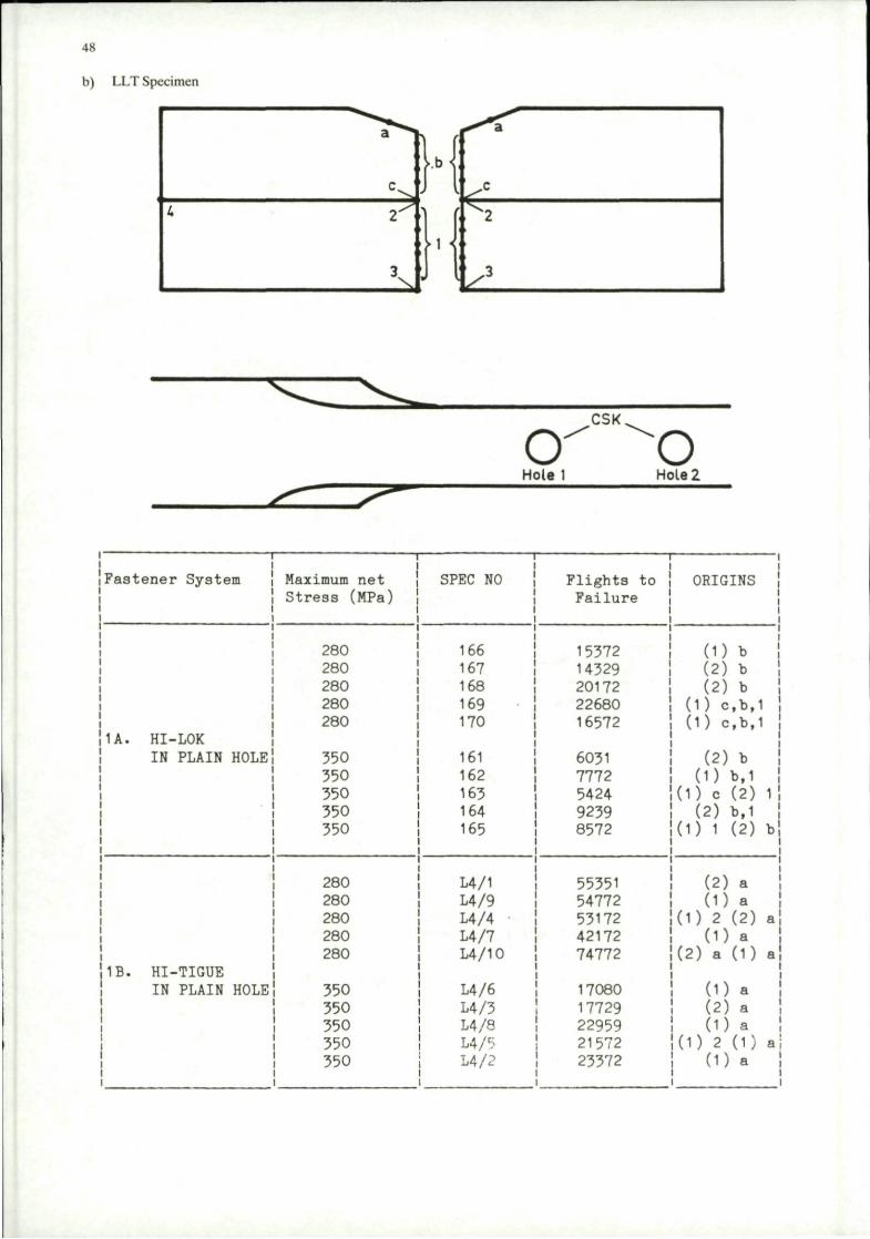
4S
b) LLT Specimen
CSK cr o Hole 1 Hole 2
Fastener System
11 A. HI-LOK IN PLAIN HOLE!
|1B. HI-TIGUE IN PLAIN HOLE I
I
i i
i i
Maximum net Stress (MPa)
280 280 280 280 280
350 350 350 350 350
280 280 280 280 280
350 350 350 350 350
SPEC NO
166 167 168 169 170
161 162 163 164 165
L4/1 L4/9 L4/4 L4/7 L4/10
L4/6 L4/3 14/8 L4/5 L4/2
Flights to Failure
15372 14329 20172 22680 16572
6031 7772 5424 9239 8572
55351 54772 53172 42172 74772
17080 17729 22959 21572 23372
ORIGINS
(D b (2) b (2) b
(1) c,b,1 (D c,b,1
(2) b (D b,1
(D c (2) ll (2) b,1
(D 1 (2) bj
(2) a (D a
(D 2 (2) a! (D a
(2) a (1) a1,
(D a (2) a (D a
KD 2 (1) aj (1) a
i

49
1
Fastener System i
!1C- HI-LOK IN COLD-WORKED HOLE
I ID- HUCK-EXL IN COLD-WORKED HOLE
i
Max imum net Stress (MPa)
280 280 280 280
350 350 350 350
280 280 280
350 350 350 350
SPEC NO
186 187 189 190
181 182 183 185
196 198 200
191 193 194 195
Flights to Failure
49231 118194 115231 99031
18759 61325 46586
83591
79972 115021 97031
69611 66231 33431 47943
ORIGINS
(D 2,1 (2) b,2 (2) b,2 (D 3.1
(D 1,2 (D b,1 (D 4.1 (D 1,3
(2) 1 (2) c,b (2) a
(D 2 (D a (D 2 (2) a,b
Observations of LLT joints
(1) Failure from hole (1) was more common than from hole (2) (60% at (1) 40% at (2)) but in no systematic way.
(2) Failure from the countersinks was observed only with high interference fit fasteners.
(3) All of the failures with system IB originated at the countersinks, only 50% with system ID originated at the countersink.
(4) All of the failures with fastener systems 1A and 1C originated from multiple origins at the bore of the hole.
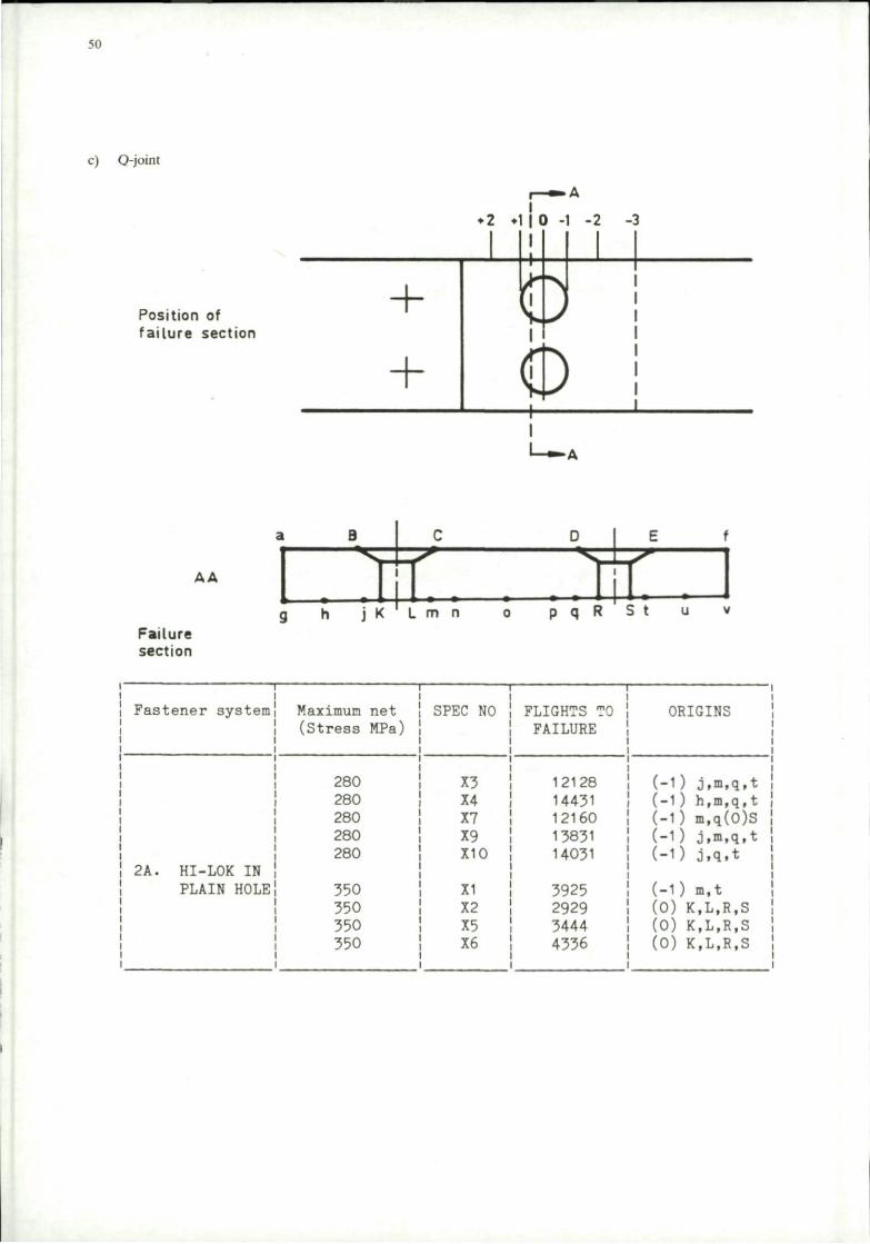
so
c) Q-joint
Position of fa i lu re section
AA
Failure section
•1
Fastener system:
2A. HI-LOK IN PLAIN HOLE!
I i i i
i i
Maximum (St ress
280 280 280 280 280
350 350 350 350
net MPa)
SPEC NO
X3 X4 X7 X9 X10
XI X2 X5 X6
FLIGHTS TO FAILURE
12128 14431 12160 13831 14031
3925 2929 3444 4336
i
ORIGINS
(-1) j,m,q,t (-1) h,m,q,t ! (-1) m.q(0)S (-1) j,m,q,t i (-1) j,q,t
(-1) m,t (0) K.L.R.S (0) K,L,R,S (0) K.L.R.S
i

51
Fastener system Maximum net Stress (MPa)
280 280 280
i
2B. HI-LOK IN COLD WORKED HOLE
280 280
350 350 350 350
1 1 i i i
i i | i i i
! 2C. HI-TIGUE IN PLAIN HOLE
280 280 280 280 280
350 350 350 350 350 350
280 280 280 280 280
! 2D. HI-TIGUE IN] COLD WORKED 350 HOLE
i
350 350 350 350
SPEC NO
CW2 CW4 CW6
CW9 CW10
CW3 CW5 CW7 CWS
12 13 14 17
15 16 19 20 21 22
4 5 6 7 10
2
3 8
9 11
FLIGHTS TO FAILURE
9631 14424 12329 16224 17631
3801 3172 3624 5323
78 032 25 225 30 860 18 530
15825 21730 11 173 16 385 8 232 13 573
25 573 45 632 77 330 111 393 91 225
38 981 32 695 16 840
11 159 7997
ORIGIN
(-2) g.(-D (-2) o,p (-1.5) 0(0)K (-1 .5) h,q,u (-1 ) j,m,p,t,u
(0) K.L.q.S (0) K,L,S (0) K,L,R (0) K.L,_.,(-. )o,ul
(+1) B,(0),L (+1) E,(0),R
( + D B (+1) D,E
( + 1 ) E (-D L,q (-3) u (-0 q,t
(-D n ( + 1 ) E
i
(+2) a •1 (+2)f(0)R •2
(-Dv(O)B I i
(-5) P (-D h (-3) u (-1) n (-2) u
*1 Failure from defect near end plate *2 Failure from fasteners in controlling section
Q-joint Summary
Fastener system/stress level — Failure site
2 A/low — On -1 line, just away from edge of hole 2A/high — On 0 line, at edge of hole.
2B/low — On -1.5 line, well away from edge of hole 2B/high — On 0 line, at edge of hole.
2C/low — On +1 line, at edge of countersink 2C/high — On+1 line, at edge of countersink or
On -1 line, near edge of hole.
2D/low — Various — edge of specimen 2D/high — On -1.5 line, well away from edge of hole.
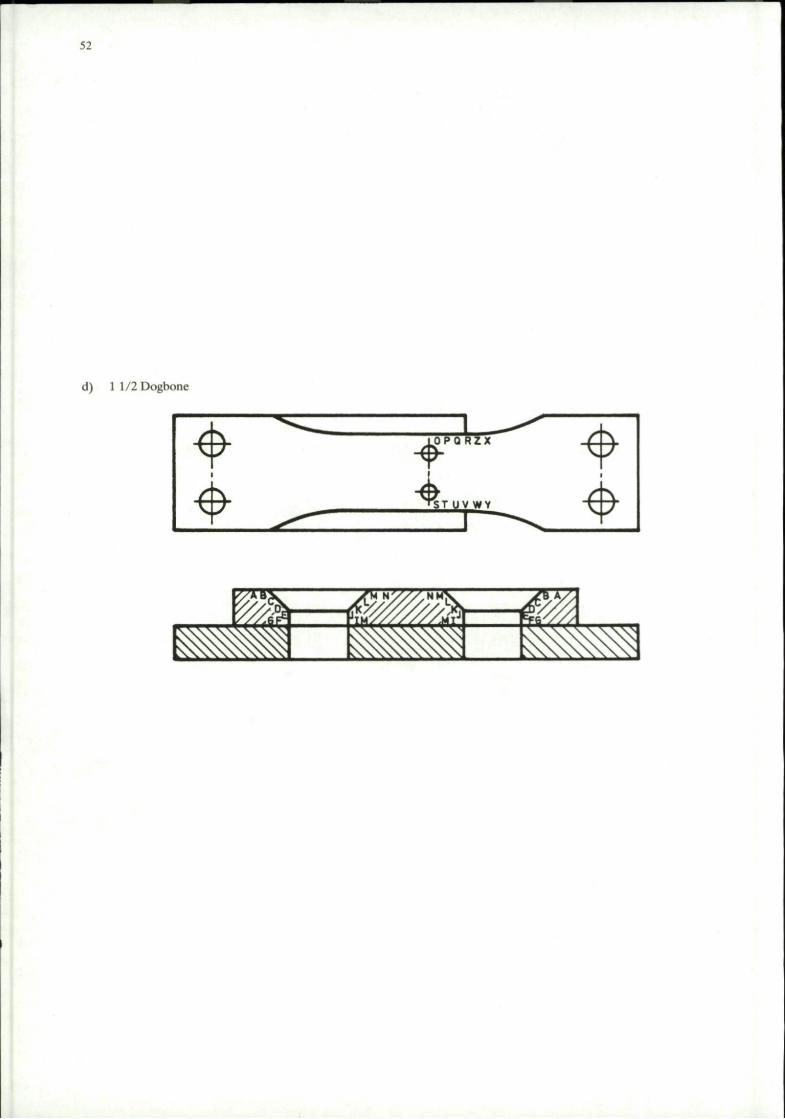
52
d) 1 1/2Dogbone
*
4 1
O P Q R Z X
f T 5 T U V W zzzr
*
4 ^S »^S i
55 _ ^ £

53
Fast
i
1 I 2A. i
i
1 i i i i
2B.
i i i
2C. i
2D.
i
| 2A.
ener system
HI-LOK IN PLAIN HOLE
HI-LOK IN COLD WORKED HOLE
HI-TIGUE IN PLAIN HOLE
HI-TIGUE IN COLD WORKED HOLE
HI-LOK IN PLAIN HOLE
(COMPATABILITY)
Maximum net Stress (MPa)
268 268 268 268
335 335 335 335
268 268 268 268
335 335 335 335
•
268
268
335 335 335 335
268 268 268
335 335 335 335
335 335 335
SPEC NO
Cl C5
C4 C2 C3 C8
D1 D2 D6
D7 D5 D8 D3
A3 A1 A2
FLIGHTS TO FAILURE
18411 60372 56972 63831
9559 15419 23373 22231
29572 40431 58231 35759
13524 14231 17962 19172
30764 36572
9983 16734 14067 11780
37146 42640 28265
19007 17308 14946 14564
11165 13826 19955
ORIGIN
S R S E
F S F E
S R-*W S R-»V
R *V R P + T G
G H
G U U G
A Y Q
P P B T
F E G
i

54
1 1 /2 Dogbone Summary
Fastener system/stress level — Failure site
2 A/low — From edge of hole at interface or just forward of hole. 2A/high — From edge of hole at interface or just forward of hole.
2B/low — Just forward of hole or at edge of side plate. 2B/high — At edge of side plate or from edge of hole at interface.
2C/low — Just away from edge of hole at interface 2C/high — Just away from edge of hole at interface or forward of fastener holes.
2D/low — Various — away from fastener hole on top surface. 2D/high — Just forward of fastener hole on top surface.

e) X-joint
55
a 1
b 2
3 c
U
d 5 a
6 f
q 7
h 8
I Fast i
i i i
i
i i i
2A.
| 2B. i i i i i i i i i i
ener system
HI-LOK IN PLAIN HOLE
HI-LOK IN COLD WORKED HOLE
Max imura net Stress (MPa)
200 200 200 200
267 267 267 267
200 200 200 200
267 267 267 267
SPEC NO
41 .6 41.7 41 .8 41.2
41 .1 41-3 41.4 41-5
42.4 42.5 42.6 42.8
42.1 42.2
42.3 42.7
FLIGHTS TO FAILURE
13860 16972 13180 13772
5425 5329 5590 6280
42772 30224 35631 27630
10929 11972 11372 6172
i
ORIGIN
1-6 a,b,d-h a-e,g a-f
a-f,h a-h a-f
a,c-h
1-6,h 1-8 1-8
1,3-6,8
a-h a-h
a,c-h 1-8
i
X-joint Summary
Fastener system/stress level — Failure site
2A/low — from fastener holes in base plate 2A/high — from fastener holes in base plate
2B/low — from fastener holes in splice plate 2B/high — from fastener holes in base plate
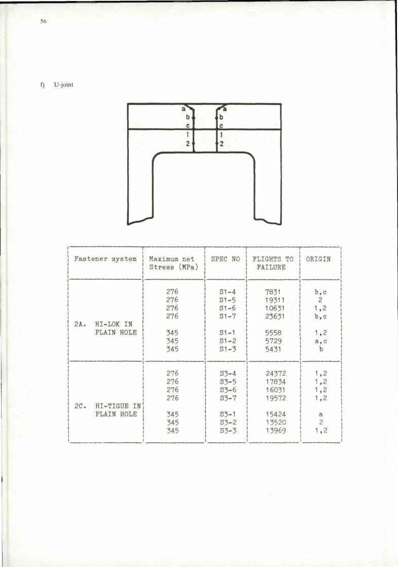
56
f) U-joint
b . b c c 1 2
f 1 2
" >
i -\
Fastener system
! 2A. HI-LOK IN PLAIN HOLE
j 2C. HI-TIGUE IN PLAIN HOLE
Max imum net Stress (MPa)
276 276 276 276
345 345 345
276 276 276 276
345 345 345
SPEC NO
S1-4 S1-5 S1-6 SI-7
S1-1 S1-2 S1-3
S3-4 S3-5 S3-6 S3-7
S3-1 S3-2 S3-3
FLIGHTS TO FAILURE
7831 19311 10631 23631
5558 5729 5431
24372 17834 16031 19572
15424 13520 13969
ORIGIN
b,c 2 1.2 b,c
1.2 a,c b
1,2 1.2 1,2 1,2
a 2 1,2
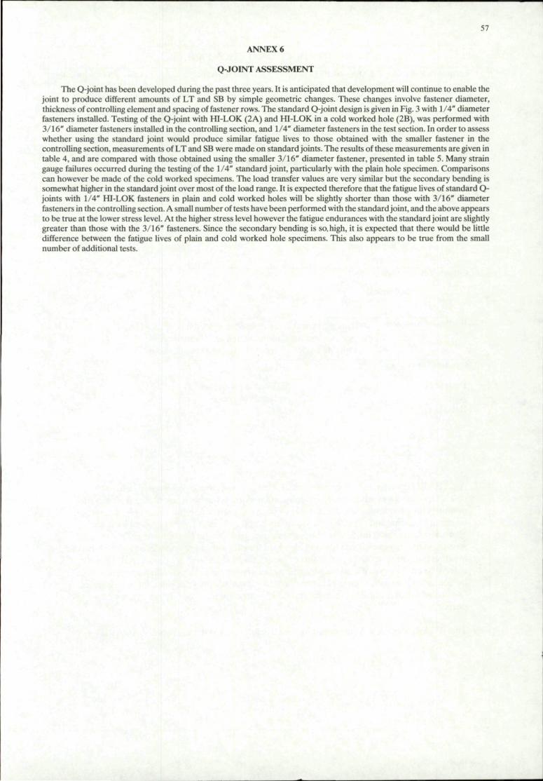
57
ANNEX 6
Q-JOINT ASSESSMENT
The Q-joint has been developed during the past three years. It is anticipated that development will continue to enable the joint to produce different amounts of LT and SB by simple geometric changes. These changes involve fastener diameter, thickness of controlling element and spacing of fastener rows. The standard Q-joint design is given in Fig. 3 with 1/4" diameter fasteners installed. Testing of the Q-joint with HI-LOK (2A) and HI-LOK in a cold worked hole (2B), was performed with 3/16" diameter fasteners installed in the controlling section, and 1/4" diameter fasteners in the test section. In order to assess whether using the standard joint would produce similar fatigue lives to those obtained with the smaller fastener in the controlling section, measurements of LT and SB were made on standard joints. The results of these measurements are given in table 4, and are compared with those obtained using the smaller 3/16" diameter fastener, presented in table 5. Many strain gauge failures occurred during the testing of the 1/4" standard joint, particularly with the plain hole specimen. Comparisons can however be made of the cold worked specimens. The load transfer values are very similar but the secondary bending is somewhat higher in the standard joint over most of the load range. It is expected therefore that the fatigue lives of standard Q-joints with 1/4" HI-LOK fasteners in plain and cold worked holes will be slightly shorter than those with 3/16" diameter fasteners in the controlling section. A small number of tests have been performed with the standard joint, and the above appears to be true at the lower stress level. At the higher stress level however the fatigue endurances with the standard joint are slightly greater than those with the 3/16" fasteners. Since the secondary bending is so. high, it is expected that there would be little difference between the fatigue lives of plain and cold worked hole specimens. This also appears to be true from the small number of additional tests.

REPORT DOCUMENTATION PAGE
1. Recipient's Reference 2. Originator's Reference
AGARD-AG-304
3. Further Reference
ISBN 92-835-0429-1
4. Security Classification of Document
UNCLASSIFIED
5. Originator Advisory Group for Aerospace Research and Development North Atlantic Treaty Organization 7 rue Ancelle, 92200 Neuilly sur Seine, France
6. Title STANDARD FATIGUE TEST SPECIMENS FOR FASTENER EVALUATION
7. Presented at
8. Author(s)/Editor(s) by Robin Cook
9. Date November 1987
10. Author's/Editor's Address
See flyleaf
11. Pages
64
12. Distribution Statement This document is distributed in accordance with AGARD policies and regulations, which are outlined on the Outside Back Covers of all AGARD publications.
13. Keywords/Descriptors
Fastener Joints Bend properties
Fatigue properties Loads (forces)
14. Abstract
An AGARD coordinated programme which examines the fatigue performance and joint characteristics of a number of mechanically fastened joints has been completed. This report describes the programme which examines mechanically fastened joints with (1) no or low secondary bending and (2) with high secondary bending. In part 1, three types of joint are assessed which exhibit no, low and high amounts of load transfer by the fastener. The no load transfer joint was rejected and low and high load transfer joint were considered to be equivalent in rating fastener systems. In part 2, three types of single shear joint are considered. They are compared on the basis of load transfer and secondary bending characteristics and also on the fatigue endurance with a range of fastener systems installed. Only one joint, the UK designed O-joint, adequately fulfilled the requirements of a standard joint for fastener evaluation purposes.
This AGARDograph was sponsored by the Structures and Materials Panel of AGARD.
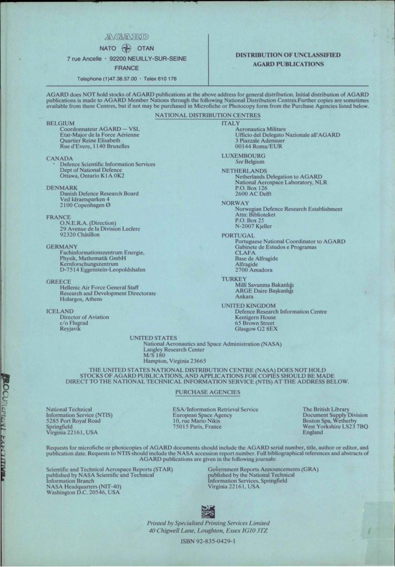
Ms.(&£S3m NATO t $ OTAN
7 rue Ancelle • 92200 NEUILLY-SUR-SEINE
FRANCE
Telephone (1)47.38,57.00 • Telex 610 176
DISTRIBUTION OF UNCLASSIFIED
AGARD PUBLICATIONS
AGARD does NOT hold stocks of AGARD publications at the above address for general distribution. Initial distribution of AGARD publications is made to AGARD Member Nations through the following National Distribution Centres.Further copies are sometimes available from these Centres, but if not may be purchased in Microfiche or Photocopy form from the Purchase Agencies listed below.
NATIONAL DISTRIBUTION CENTRES BELGIUM
Coordonnateur AGARD - VSL Etat- Major de la Force Aerienne Quartier Reine Elisabeth Rue d'Evere. 1140 Bruxelles
CANADA • Defence Scientific Information Services
Dept of National Defence Ottawa, Ontario K1A 0K2
DENMARK Danish Defence Research Board Ved Idraetsparken 4 2100 Copenhagen 0
FRANCE O.N.E.R.A. (Direction) 29 Avenue de la Division Leclerc 92320 Chatillon
GERMANY Fachinformationszentrum Energie, Physik, Mathematik GmbH Kernforschungszentrum D-7514 Eggenstein-Leopoldshafen
GREECE Hellenic Air Force General Staff Research and Development Directorate Holargos, Athens
ICELAND Director of Aviation c/o Flugrad Reyjavik
ITALY Aeronautica Militarc Ufficio del Delegate Nazionale all"AGARD 3 Piazzale Adenauer 00144 Roma/EUR
LUXEMBOURG See Belgium
NETHERLANDS Netherlands Delegation to AGARD National Aerospace Laboratory, NLR P.O.Box 126 2600 AC Delft
NORWAY Norwegian Defence Research Establishment Attn: Biblioteket P.O. Box 25 N-2007 Kjeller
PORTUGAL Portuguese National Coordinator to AGARD Gabinete de Estudos e Programas CLAFA Base de Alfragide Alfragide 2700 Amadora
TURKEY Mill! Savunma Bakanligi ARGE Daire Baskanligi Ankara
UNITED KINGDOM Defence Research Information Centre Kcntigern House 65 Brown Street Glasgow G2 SEX
r c
UNITED STATES National Aeronautics and Space Administration (NASA) Langley Research Center M/S 180 Hampton, Virginia 23665
THE UNITED STATES NATIONAL DISTRIBUTION CENTRE (NASA) DOES NOT HOLD STOCKS OF AGARD PUBLICATIONS, AND APPLICATIONS FOR COPIES SHOULD BE MADE
DIRECT TO THE NATIONAL TECHNICAL INFORMATION SERVICE (NTIS) AT THE ADDRESS BELOW.
PURCHASE AGENCIES
National Technical Information Service (NTIS) 5285 Port Royal Road Springfield Virginia 22161, USA
ESA/Information Retrieval Service European Space Agency 10, rue Mario Nikis 75015 Paris, France
The British Library Document Supply Division Boston Spa, Wetherby West Yorkshire LS23 7BO England
Requests for microfiche or photocopies of AGARD documents should include the AGARD serial number, title, author or editor, and publication date. Requests to NTIS should include the NASA accession report number. Full bibliographical references and abstracts of
AGARD publications are given in the following journals;
Scientific and Technical Aerospace Reports (STAR) published by NASA Scientific and Technical Information Branch NASA Headquarters (NIT-40) Washington D.C. 20546, USA
Government Reports Announcements (GRA) published by the National Technical Information Services, Springfield Virginia 22161, USA
Printed by Specialised Priming Services Limited 40 ( higwell Lane, Loughton, Essex IGI03TZ
ISBN 92-835-0429-1