AG053013 SmartLinx PROFINET instruction and use...The PROFINET master sets the PROFINET Device Name...
24
Siemens Canada Limited Siemens Milltronics Process Instruments 1954 Technology Drive, P.O. Box 4225 Peterborough, Ontario K9J 7B1 / Canada Tel.: (705) 745-2431 Fax: (705) 741-0466 www.siemens.com/sensorsystems AG053013 SmartLinx PROFINET instruction and use Objective: Show the user how to configure and use a PROFINET SmartLinx communication module. While every effort was made to verify the following information, no warranty of accuracy or usability is expressed or implied. All hardware and software in this document is not supplied or supported by Siemens. Use of the described equipment in this document is at the user’s discretion. Siemens holds no responsibility for such use. PROFINET is an open standard controlled by PROFIBUS/PROFINET INTERNATIONAL. More information is available on the web site at www.profibus.com . Specifications Application: • Compatible with a master device on a PROFINET bus Compatible Devices: • Milltronics BW500 • Milltronics BW500/L • Milltronics SF500 Communication Settings: • IP address & PROFINET Device Name (configured over the network via a PROFINET master) Connection: • RJ45 Installation The SmartLinx module is either shipped already installed in the Siemens Milltronics device or separately for on-site installation. Refer to the operating instructions of your Siemens Milltronics device for details on module location and physical installation. Compatibility For the SmartLinx PROFINET card there are different hardware and software configurations available depending on the equipment used. Software Compatibility For the SmartLinx card to work, the firmware of the device must be greater than or equal to the firmware listed in the chart below. Milltronics BW500/L 3.13.04-00 Milltronics BW500 3.13.04-00 Milltronics SF500 3.13.04-00 APPLICATION GUIDE
Transcript of AG053013 SmartLinx PROFINET instruction and use...The PROFINET master sets the PROFINET Device Name...
Siemens Canada Limited Siemens Milltronics Process Instruments
1954 Technology Drive, P.O. Box 4225 Peterborough, Ontario K9J 7B1 / Canada
Tel.: (705) 745-2431 Fax: (705) 741-0466 www.siemens.com/sensorsystems
AG053013
SmartLinx PROFINET instruction and use
Objective: Show the user how to configure and use a PROFINET SmartLinx communication module.
While every effort was made to verify the following information, no warranty of accuracy or usability is expressed or implied. All hardware and software in this document is not supplied or supported by Siemens. Use of the described equipment in this document is at the user’s discretion. Siemens holds no responsibility for such use. PROFINET is an open standard controlled by PROFIBUS/PROFINET INTERNATIONAL. More information is available on the web site at www.profibus.com.
Specifications Application: • Compatible with a master device on a PROFINET bus
Compatible Devices: • Milltronics BW500 • Milltronics BW500/L • Milltronics SF500
Communication Settings: • IP address & PROFINET Device Name (configured over the network via a PROFINET master) Connection: • RJ45
Installation The SmartLinx module is either shipped already installed in the Siemens Milltronics device or separately for on-site installation. Refer to the operating instructions of your Siemens Milltronics device for details on module location and physical installation.
Compatibility For the SmartLinx PROFINET card there are different hardware and software configurations available depending on the equipment used.
Software Compatibility For the SmartLinx card to work, the firmware of the device must be greater than or equal to the firmware listed in the chart below. Milltronics BW500/L 3.13.04-00 Milltronics BW500 3.13.04-00 Milltronics SF500 3.13.04-00
APPLICATION GUIDE
SmartLinx PROFINET AG053013 2 of 23
APPLICATION GUIDERetrofits If you are upgrading an older SmartLinx device with a new SmartLinx communication protocol, new firmware is required on the device for proper operation. Contact the factory for the latest firmware version.
Hardware Compatibility Install the SmartLinx card so that the mounting holes align and the pin connectors will mate correctly. Correct cable routing is important for electromagnetic noise suppression. Follow the routing instructions contained your device operating instructions.
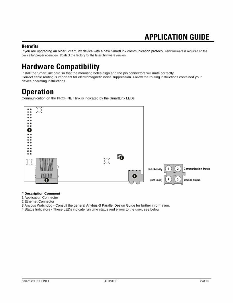
Operation Communication on the PROFINET link is indicated by the SmartLinx LEDs.
# Description Comment 1 Application Connector 2 Ethernet Connector 3 Anybus Watchdog - Consult the general Anybus-S Parallel Design Guide for further information. 4 Status Indicators - These LEDs indicate run time status and errors to the user, see below.
SmartLinx PROFINET AG053013 3 of 23
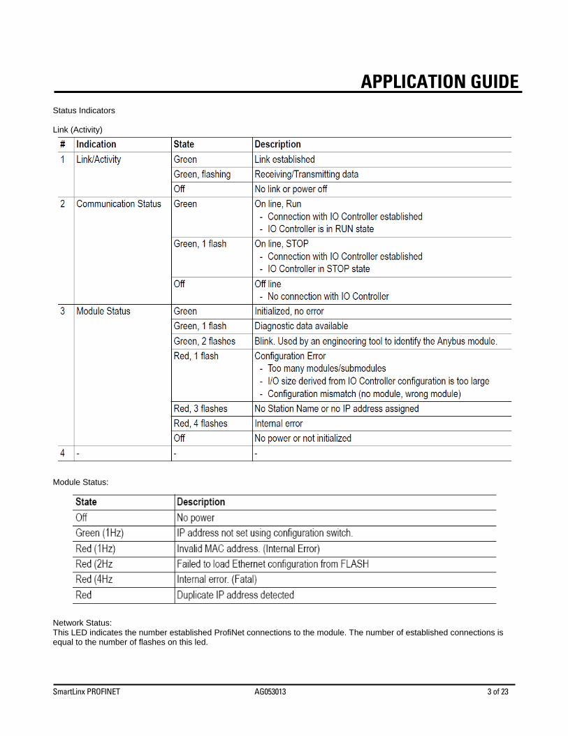
APPLICATION GUIDEStatus Indicators Link (Activity)
Module Status:
Network Status: This LED indicates the number established ProfiNet connections to the module. The number of established connections is equal to the number of flashes on this led.
SmartLinx PROFINET AG053013 4 of 23
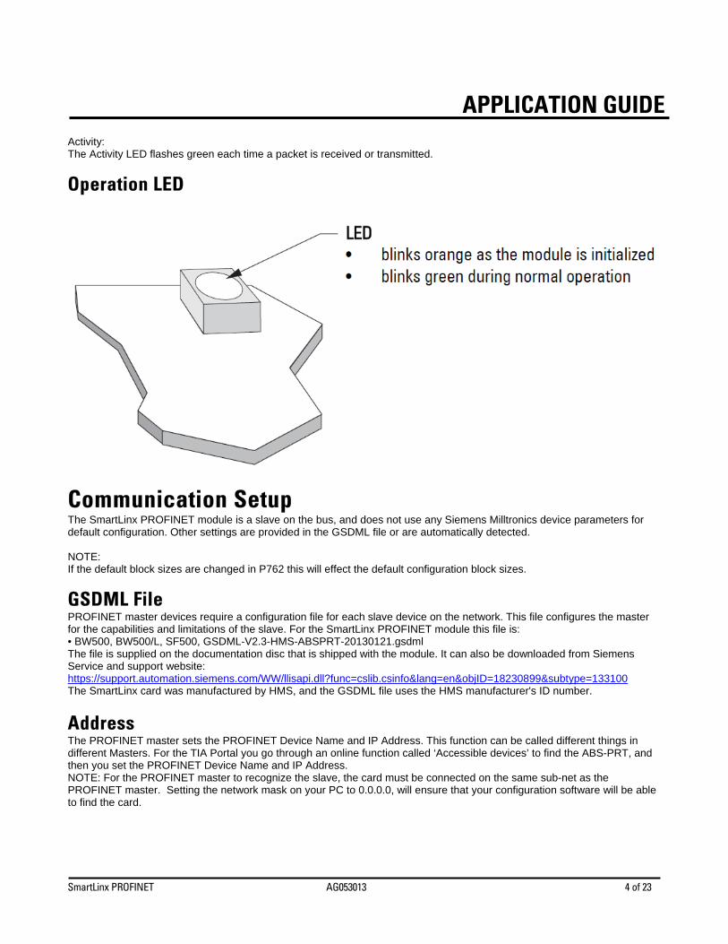
APPLICATION GUIDEActivity: The Activity LED flashes green each time a packet is received or transmitted.
Operation LED
Communication Setup The SmartLinx PROFINET module is a slave on the bus, and does not use any Siemens Milltronics device parameters for default configuration. Other settings are provided in the GSDML file or are automatically detected. NOTE: If the default block sizes are changed in P762 this will effect the default configuration block sizes.
GSDML File PROFINET master devices require a configuration file for each slave device on the network. This file configures the master for the capabilities and limitations of the slave. For the SmartLinx PROFINET module this file is: • BW500, BW500/L, SF500, GSDML-V2.3-HMS-ABSPRT-20130121.gsdml The file is supplied on the documentation disc that is shipped with the module. It can also be downloaded from Siemens Service and support website: https://support.automation.siemens.com/WW/llisapi.dll?func=cslib.csinfo&lang=en&objID=18230899&subtype=133100 The SmartLinx card was manufactured by HMS, and the GSDML file uses the HMS manufacturer's ID number.
Address The PROFINET master sets the PROFINET Device Name and IP Address. This function can be called different things in different Masters. For the TIA Portal you go through an online function called ‘Accessible devices’ to find the ABS-PRT, and then you set the PROFINET Device Name and IP Address. NOTE: For the PROFINET master to recognize the slave, the card must be connected on the same sub-net as the PROFINET master. Setting the network mask on your PC to 0.0.0.0, will ensure that your configuration software will be able to find the card.
SmartLinx PROFINET AG053013 5 of 23
APPLICATION GUIDE
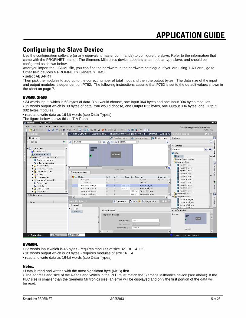
Configuring the Slave Device Use the configuration software (or any equivalent master commands) to configure the slave. Refer to the information that came with the PROFINET master. The Siemens Milltronics device appears as a modular type slave, and should be configured as shown below. After you import the GSDML file, you can find the hardware in the hardware catalogue. If you are using TIA Portal, go to Other field devices > PROFINET > General > HMS. • select ABS-PRT. Then pick the modules to add up to the correct number of total input and then the output bytes. The data size of the input and output modules is dependent on P762. The following instructions assume that P762 is set to the default values shown in the chart on page 7. BW500, SF500 • 34 words input which is 68 bytes of data. You would choose, one Input 064 bytes and one Input 004 bytes modules • 19 words output which is 38 bytes of data. You would choose, one Output 032 bytes, one Output 004 bytes, one Output 002 bytes modules. • read and write data as 16-bit words (see Data Types) The figure below shows this in TIA Portal:
BW500/L • 23 words input which is 46 bytes - requires modules of size 32 + 8 + 4 + 2 • 10 words output which is 20 bytes - requires modules of size 16 + 4 • read and write data as 16-bit words (see Data Types) Notes: • Data is read and written with the most significant byte (MSB) first. • The address and size of the Reads and Writes in the PLC must match the Siemens Milltronics device (see above). If the PLC size is smaller than the Siemens Milltronics size, an error will be displayed and only the first portion of the data will be read.
SmartLinx PROFINET AG053013 6 of 23
APPLICATION GUIDE• PROFINET diagnostic bytes are not supported, however, some diagnostic information can be accessed via reading and writing the data areas. See Application Layer.
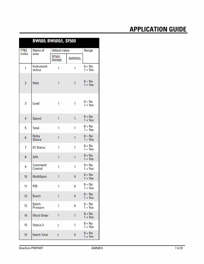
Map Element Selection P762 Map Element Selection parameter P762 allows you to select what elements to include in the Input and Output Tables. By selecting only the data required, you can reduce the amount of data being transferred over the bus. Notes: • P762 should only be modified by an advanced user who wants to limit the amount of data being transferred. See the Profibus DP SmartLinx operating instructions 7ML19981AQ03 Appendix A – Reducing the amount of data being transferred over the Bus for more details. • Changes do not take effect until after a power cycle. The chart below gives the default values for this parameter. If the default values are used then the configuration and Data Maps in the main body of this guide remain correct. If any of these values are changed, then the Data Maps will be shortened, and the configuration will change. Please see the Profibus DP SmartLinx operating instructions 7ML19981AQ03 Appendix A for details on how to use P762.
SmartLinx PROFINET AG053013 7 of 23
APPLICATION GUIDE
SmartLinx PROFINET AG053013 8 of 23
APPLICATION GUIDE
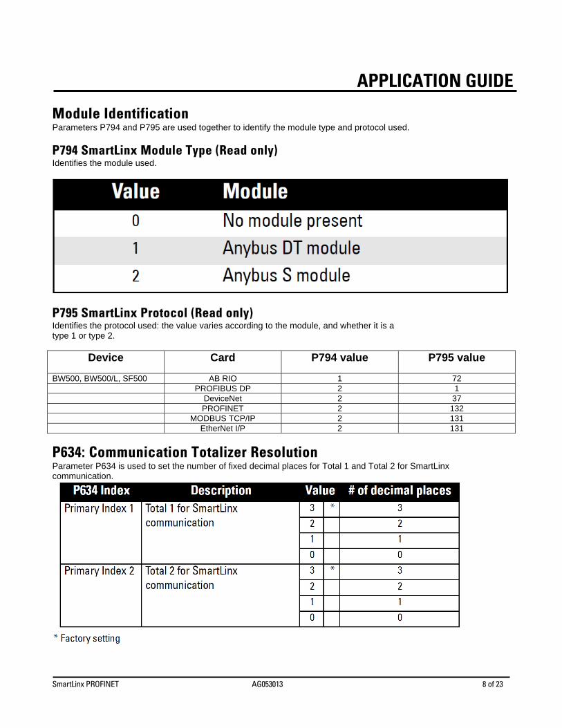
Module Identification Parameters P794 and P795 are used together to identify the module type and protocol used.
P794 SmartLinx Module Type (Read only) Identifies the module used.
P795 SmartLinx Protocol (Read only) Identifies the protocol used: the value varies according to the module, and whether it is a type 1 or type 2.
Device
Card
P794 value
P795 value
BW500, BW500/L, SF500 AB RIO 1 72 PROFIBUS DP 2 1 DeviceNet 2 37 PROFINET 2 132 MODBUS TCP/IP 2 131 EtherNet I/P 2 131
P634: Communication Totalizer Resolution Parameter P634 is used to set the number of fixed decimal places for Total 1 and Total 2 for SmartLinx communication.
SmartLinx PROFINET AG053013 9 of 23
APPLICATION GUIDE
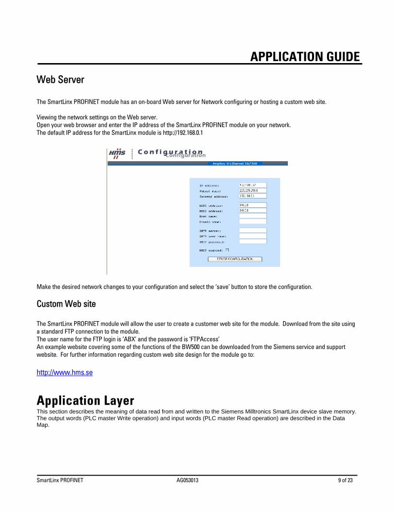
Web Server The SmartLinx PROFINET module has an on-board Web server for Network configuring or hosting a custom web site. Viewing the network settings on the Web server. Open your web browser and enter the IP address of the SmartLinx PROFINET module on your network. The default IP address for the SmartLinx module is http://192.168.0.1 Make the desired network changes to your configuration and select the ‘save’ button to store the configuration.
Custom Web site The SmartLinx PROFINET module will allow the user to create a customer web site for the module. Download from the site using a standard FTP connection to the module. The user name for the FTP login is ‘ABX’ and the password is ‘FTPAccess’ An example website covering some of the functions of the BW500 can be downloaded from the Siemens service and support website. For further information regarding custom web site design for the module go to: http://www.hms.se
Application Layer This section describes the meaning of data read from and written to the Siemens Milltronics SmartLinx device slave memory. The output words (PLC master Write operation) and input words (PLC master Read operation) are described in the Data Map.
SmartLinx PROFINET AG053013 10 of 23
APPLICATION GUIDE
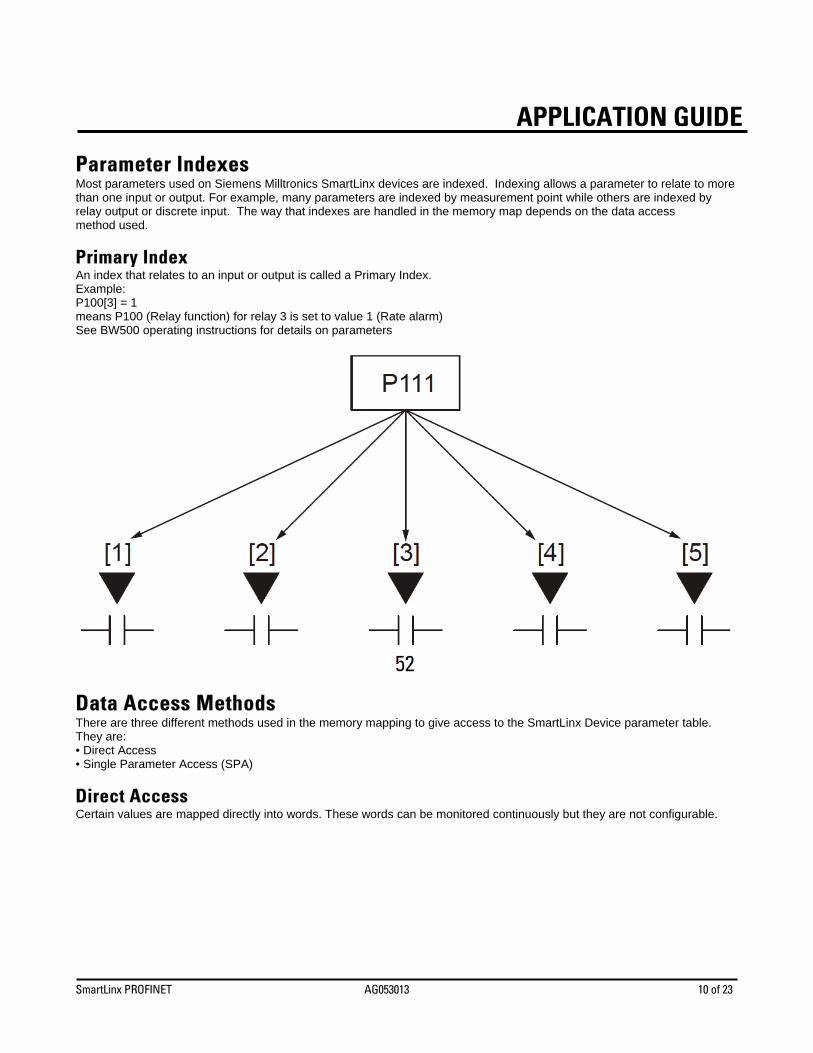
Parameter Indexes Most parameters used on Siemens Milltronics SmartLinx devices are indexed. Indexing allows a parameter to relate to more than one input or output. For example, many parameters are indexed by measurement point while others are indexed by relay output or discrete input. The way that indexes are handled in the memory map depends on the data access method used.
Primary Index An index that relates to an input or output is called a Primary Index. Example: P100[3] = 1 means P100 (Relay function) for relay 3 is set to value 1 (Rate alarm) See BW500 operating instructions for details on parameters
Data Access Methods There are three different methods used in the memory mapping to give access to the SmartLinx Device parameter table. They are: • Direct Access • Single Parameter Access (SPA)
Direct Access Certain values are mapped directly into words. These words can be monitored continuously but they are not configurable.
SmartLinx PROFINET AG053013 11 of 23
APPLICATION GUIDE
Single Parameter Access (SPA) This is a hand-shaking method where the PLC specifies: • parameter number • primary index • secondary index • decimal place • format • read/write flag • value With this method any value in the Siemens Milltronics device can be read or written.
Using Single Parameter Access (SPA) SPA allows continuous monitoring or demand programming of a parameter.
Reading a Parameter 1. Set the Read/Write flag in the output table (Write Block) to 0, “Read”. 2. Write the Parameter Number, Primary Index, Secondary Index, Decimal Place, and Format in the correct locations. Note: If there is no secondary index, then place a 0 in this location. 3. Monitor the Input table of the PLC (Read Block) and watch for the values you wrote to appear in the appropriate locations, then go to Step 4. 4. Read the requested parameter value in the Input table (Read Block). These values are continuously updated. Continue reading from these words until values for other parameters are required. At that time, go back to step 1.
Writing a Parameter 1. Set the Read/Write flag in the output table (Write Block) to 0, “Read”. 2. Write the Parameter Number, Primary Index, Secondary Index, Decimal Place, and Format in the correct locations. 3. Write the new value of the parameter into the correct location of the output memory (Write Block) 4. If the unit is not in program mode, write a 1 to the operating mode word in the output memory (Write Block). Please note that writing a 1 will only work if the word is currently a 0: if not, you need to change it to 0 before writing a 1 so it can take effect. 5. Set the Read/Write flag in the output table (Write Block) to a 1 “write”. 6. Monitor the Input table of the PLC (Read Block) and watch for the values you wrote to appear in the appropriate locations. 7. Set Read/Write flag back to 0. 8. Place unit in Run mode.
Data Map Note: The data maps shown for the Write and Read Blocks apply if P762 is set to the default values. If any of these values is changed, the data map will be shortened and the configuration will change. This section describes the meaning of the data read from and written to the Siemens Milltronics SmartLinx device.
SmartLinx PROFINET AG053013 12 of 23
APPLICATION GUIDE
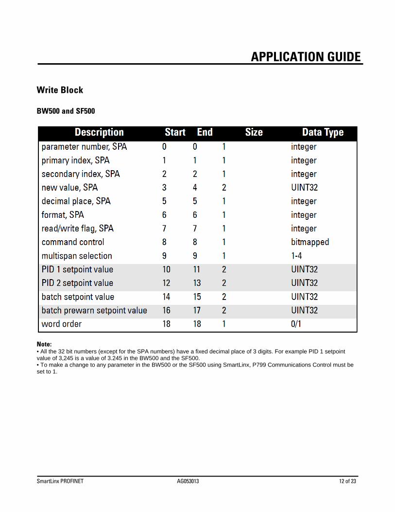
Write Block BW500 and SF500
Note: • All the 32 bit numbers (except for the SPA numbers) have a fixed decimal place of 3 digits. For example PID 1 setpoint value of 3,245 is a value of 3.245 in the BW500 and the SF500. • To make a change to any parameter in the BW500 or the SF500 using SmartLinx, P799 Communications Control must be set to 1.
SmartLinx PROFINET AG053013 13 of 23
APPLICATION GUIDE
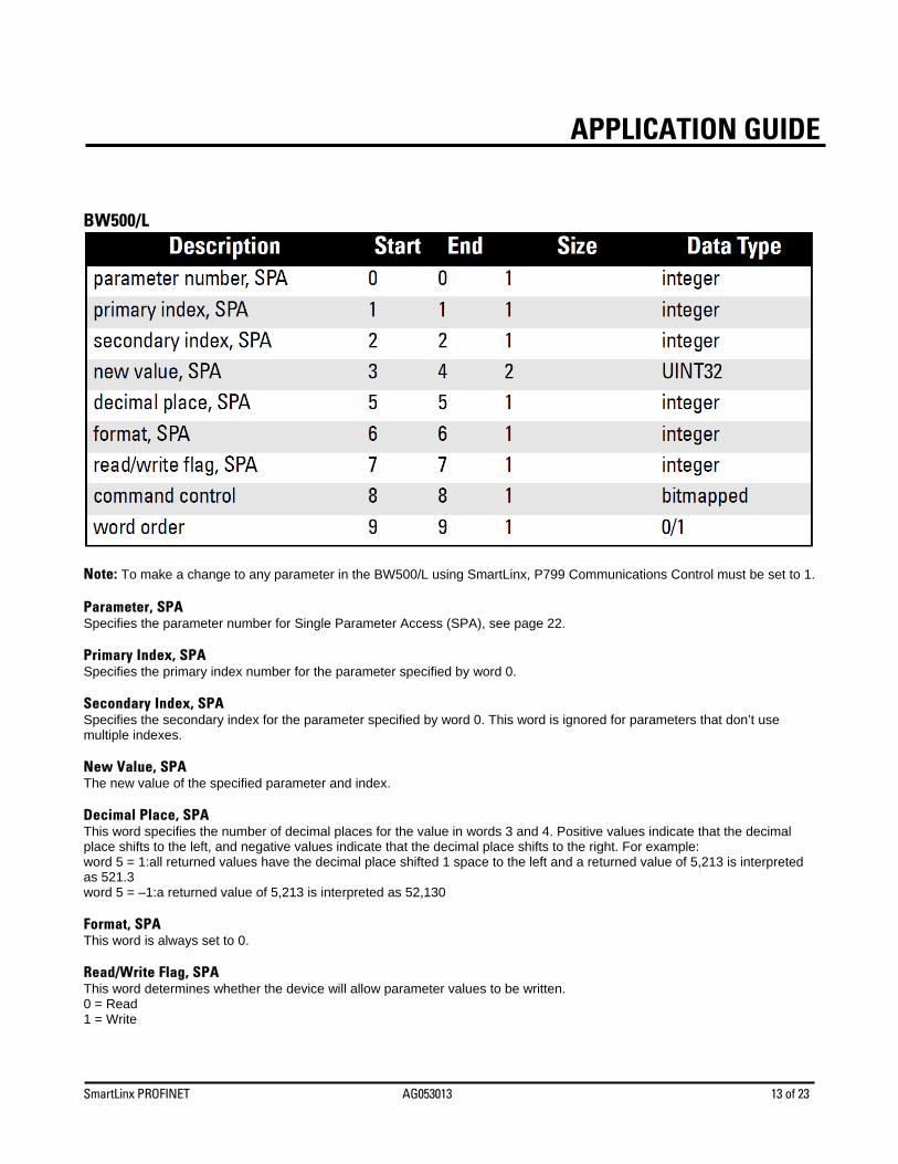
BW500/L
Note: To make a change to any parameter in the BW500/L using SmartLinx, P799 Communications Control must be set to 1. Parameter, SPA Specifies the parameter number for Single Parameter Access (SPA), see page 22. Primary Index, SPA Specifies the primary index number for the parameter specified by word 0. Secondary Index, SPA Specifies the secondary index for the parameter specified by word 0. This word is ignored for parameters that don’t use multiple indexes. New Value, SPA The new value of the specified parameter and index. Decimal Place, SPA This word specifies the number of decimal places for the value in words 3 and 4. Positive values indicate that the decimal place shifts to the left, and negative values indicate that the decimal place shifts to the right. For example: word 5 = 1:all returned values have the decimal place shifted 1 space to the left and a returned value of 5,213 is interpreted as 521.3 word 5 = –1:a returned value of 5,213 is interpreted as 52,130 Format, SPA This word is always set to 0. Read/Write Flag, SPA This word determines whether the device will allow parameter values to be written. 0 = Read 1 = Write
SmartLinx PROFINET AG053013 14 of 23
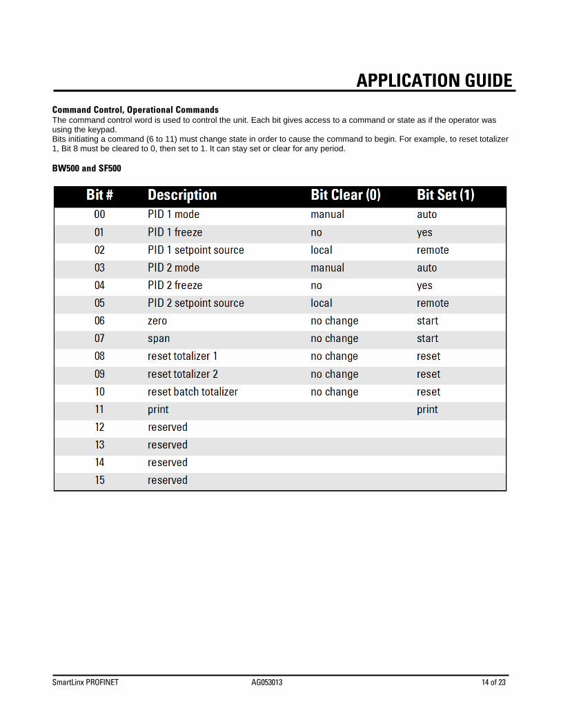
APPLICATION GUIDECommand Control, Operational Commands The command control word is used to control the unit. Each bit gives access to a command or state as if the operator was using the keypad. Bits initiating a command (6 to 11) must change state in order to cause the command to begin. For example, to reset totalizer 1, Bit 8 must be cleared to 0, then set to 1. It can stay set or clear for any period. BW500 and SF500
SmartLinx PROFINET AG053013 15 of 23
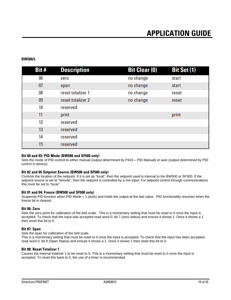
APPLICATION GUIDE BW500/L
Bit 00 and 03: PID Mode (BW500 and SF500 only) Sets the mode of PID control to either manual (output determined by P410 – PID Manual) or auto (output determined by PID control in device). Bit 02 and 05 Setpoint Source (BW500 and SF500 only) Controls the location of the setpoint. If it is set as “local”, then the setpoint used is internal to the BW500 or SF500. If the setpoint source is set to “remote”, then the setpoint is controlled by a mA input. For setpoint control through communications this must be set to “local.” Bit 01 and 04: Freeze (BW500 and SF500 only) Suspends PID function when PID Mode = 1 (auto) and holds the output at the last value. PID functionality resumes when the freeze bit is cleared. Bit 06: Zero Sets the zero point for calibration of the belt scale. This is a momentary setting that must be reset to 0 once the input is accepted. To check that the input was accepted read word 0, bit 7 (zero status) and ensure it shows 1. Once it shows a 1 then reset this bit to 0. Bit 07: Span Sets the span for calibration of the belt scale. This is a momentary setting that must be reset to 0 once the input is accepted. To check that the input has been accepted, read word 0, bit 8 (Span Status) and ensure it shows a 1. Once it shows 1 then reset this bit to 0. Bit 08: Reset Totalizer 1 Causes the internal totalizer 1 to be reset to 0. This is a momentary setting that must be reset to 0 once the input is accepted. To reset this back to 0, the use of a timer is recommended.
SmartLinx PROFINET AG053013 16 of 23
APPLICATION GUIDEBit 09: Reset Totalizer 2 Causes the internal totalizer 2 to be reset to 0. This is a momentary setting that must be reset to 0 once the input is accepted. To reset this back to 0, the use of a timer is recommended. Bit 10: Reset Batch Totalizer (BW500 and SF500 only) Causes the batch totalizer to be reset to 0. This is a momentary setting that must be reset to 0 once the input is accepted. To reset this back to 0, the use of a timer is recommended. Bit 11: Print Starts print operation. One of the communication ports on your Milltronics Integrator must be configured for a printer. This is a momentary setting that must be reset to 0 once the input is accepted. To reset this back to 0, the use of a timer is recommended. Multispan Selection (BW500 and SF500) Sets the current span (1 to 4). Any parameters that relate to span will use this value to determine which span is referenced. See the operating instructions for the BW500 or SF500 for more information on multispan. PID Setpoints (BW500 and SF500 only) Contain the current setpoint values as P415 in the Milltronics BW500 or SF500. To write these setpoints bits 02 and 05 in word 8 - Control must be set to “local.” Batch Setpoint (BW500 and SF500 only) Contain the current setpoint value as P564 in the Milltronics BW500 or SF500. Batch Prewarn Setpoint (BW500 and SF500 only) Contain the current setpoint value as P567 in the Milltronics BW500 or SF500. Word Order This word controls which word comes first in the UINT32 integers. For a value 0, the most significant word is given first. For a value 1, the least significant word is given first. 0 = MSW first 1 = LSW first
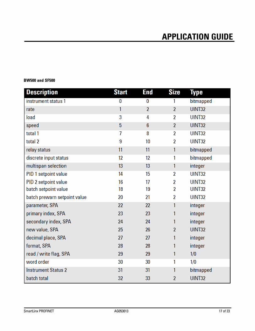
Read Block Values returned in the words in the Read are in response to the Write to the Siemens Milltronics SmartLinx device. Words 0 through 20 have values with fixed meanings and formats. This means that you do not have to start communications with a Write in order to use Read, the data is always there. Words 22 through 29 are values returned in response to writing words 0 through 7 for Single Parameter Access (SPA), see Write Block on page 12.
SmartLinx PROFINET AG053013 17 of 23
APPLICATION GUIDE BW500 and SF500
SmartLinx PROFINET AG053013 18 of 23
APPLICATION GUIDE
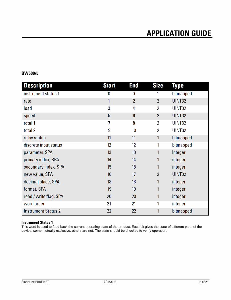
BW500/L
Instrument Status 1 This word is used to feed back the current operating state of the product. Each bit gives the state of different parts of the device, some mutually exclusive, others are not. The state should be checked to verify operation.
SmartLinx PROFINET AG053013 19 of 23
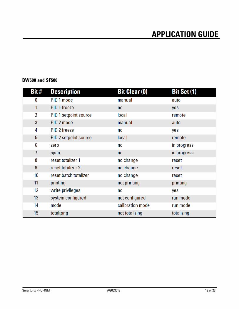
APPLICATION GUIDE BW500 and SF500
SmartLinx PROFINET AG053013 20 of 23
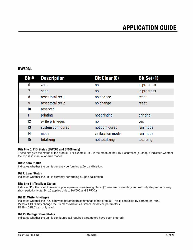
APPLICATION GUIDE BW500/L
Bits 0 to 5: PID Status (BW500 and SF500 only) These bits give the status of the product. For example Bit 0 is the mode of the PID 1 controller (if used). It indicates whether the PID is in manual or auto modes. Bit 6: Zero Status Indicates whether the unit is currently performing a Zero calibration. Bit 7: Span Status Indicates whether the unit is currently performing a Span calibration. Bits 8 to 11: Totalizer Status Indicate “1” if the reset totalizer or print operations are taking place. (These are momentary and will only stay set for a very short period.) (Note: Bit 10 applies only to BW500 and SF500.) Bit 12: Write Privileges Indicates whether the PLC can write parameters/commands to the product. This is controlled by parameter P799. P799 = 1 PLC may change the Siemens Milltronics SmartLinx device parameters. P799 = 0 PLC can only read. Bit 13: Configuration Status Indicates whether the unit is configured (all required parameters have been entered).
SmartLinx PROFINET AG053013 21 of 23
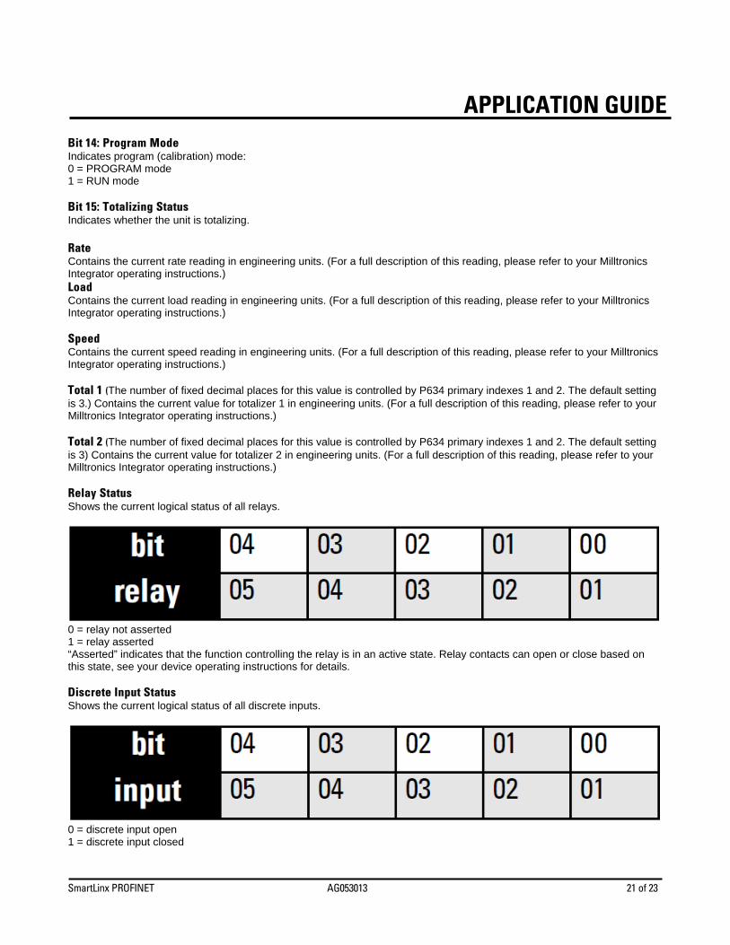
APPLICATION GUIDEBit 14: Program Mode Indicates program (calibration) mode: 0 = PROGRAM mode 1 = RUN mode Bit 15: Totalizing Status Indicates whether the unit is totalizing. Rate Contains the current rate reading in engineering units. (For a full description of this reading, please refer to your Milltronics Integrator operating instructions.) Load Contains the current load reading in engineering units. (For a full description of this reading, please refer to your Milltronics Integrator operating instructions.) Speed Contains the current speed reading in engineering units. (For a full description of this reading, please refer to your Milltronics Integrator operating instructions.) Total 1 (The number of fixed decimal places for this value is controlled by P634 primary indexes 1 and 2. The default setting is 3.) Contains the current value for totalizer 1 in engineering units. (For a full description of this reading, please refer to your Milltronics Integrator operating instructions.) Total 2 (The number of fixed decimal places for this value is controlled by P634 primary indexes 1 and 2. The default setting is 3) Contains the current value for totalizer 2 in engineering units. (For a full description of this reading, please refer to your Milltronics Integrator operating instructions.) Relay Status Shows the current logical status of all relays.
0 = relay not asserted 1 = relay asserted “Asserted” indicates that the function controlling the relay is in an active state. Relay contacts can open or close based on this state, see your device operating instructions for details. Discrete Input Status Shows the current logical status of all discrete inputs.
0 = discrete input open 1 = discrete input closed
SmartLinx PROFINET AG053013 22 of 23
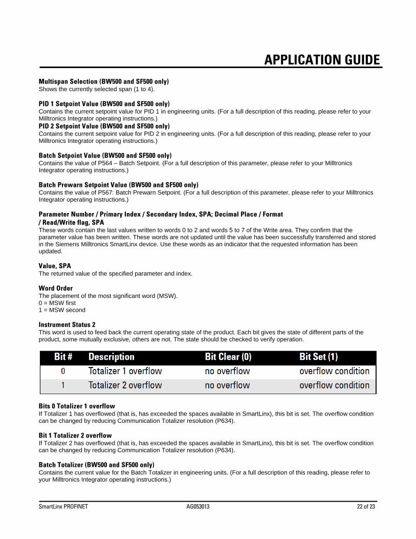
APPLICATION GUIDEMultispan Selection (BW500 and SF500 only) Shows the currently selected span (1 to 4). PID 1 Setpoint Value (BW500 and SF500 only) Contains the current setpoint value for PID 1 in engineering units. (For a full description of this reading, please refer to your Milltronics Integrator operating instructions.) PID 2 Setpoint Value (BW500 and SF500 only) Contains the current setpoint value for PID 2 in engineering units. (For a full description of this reading, please refer to your Milltronics Integrator operating instructions.) Batch Setpoint Value (BW500 and SF500 only) Contains the value of P564 – Batch Setpoint. (For a full description of this parameter, please refer to your Milltronics Integrator operating instructions.) Batch Prewarn Setpoint Value (BW500 and SF500 only) Contains the value of P567: Batch Prewarn Setpoint. (For a full description of this parameter, please refer to your Milltronics Integrator operating instructions.) Parameter Number / Primary Index / Secondary Index, SPA; Decimal Place / Format / Read/Write flag, SPA These words contain the last values written to words 0 to 2 and words 5 to 7 of the Write area. They confirm that the parameter value has been written. These words are not updated until the value has been successfully transferred and stored in the Siemens Milltronics SmartLinx device. Use these words as an indicator that the requested information has been updated. Value, SPA The returned value of the specified parameter and index. Word Order The placement of the most significant word (MSW). 0 = MSW first 1 = MSW second Instrument Status 2 This word is used to feed back the current operating state of the product. Each bit gives the state of different parts of the product, some mutually exclusive, others are not. The state should be checked to verify operation.
Bits 0 Totalizer 1 overflow If Totalizer 1 has overflowed (that is, has exceeded the spaces available in SmartLinx), this bit is set. The overflow condition can be changed by reducing Communication Totalizer resolution (P634). Bit 1 Totalizer 2 overflow If Totalizer 2 has overflowed (that is, has exceeded the spaces available in SmartLinx), this bit is set. The overflow condition can be changed by reducing Communication Totalizer resolution (P634). Batch Totalizer (BW500 and SF500 only) Contains the current value for the Batch Totalizer in engineering units. (For a full description of this reading, please refer to your Milltronics Integrator operating instructions.)
SmartLinx PROFINET AG053013 23 of 23
APPLICATION GUIDE
Data Types The Siemens Milltronics SmartLinx device parameters take on many values in various formats, as discussed in the Siemens Milltronics SmartLinx device operating instructions. For the convenience of the programmer, those values are converted to and from 16-bit integer numbers, since those are easily handled by most PLCs.
Integer Integers used on the Mass Dynamics products can have any valid value. So, the entire range from –32,768 to 32,767 or 0 to 65,535 is available and no values are used as error conditions.
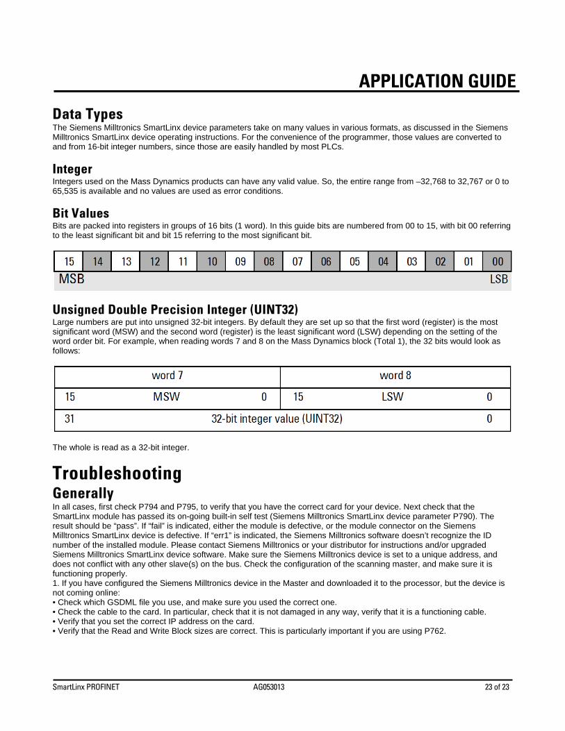
Bit Values Bits are packed into registers in groups of 16 bits (1 word). In this guide bits are numbered from 00 to 15, with bit 00 referring to the least significant bit and bit 15 referring to the most significant bit.
Unsigned Double Precision Integer (UINT32) Large numbers are put into unsigned 32-bit integers. By default they are set up so that the first word (register) is the most significant word (MSW) and the second word (register) is the least significant word (LSW) depending on the setting of the word order bit. For example, when reading words 7 and 8 on the Mass Dynamics block (Total 1), the 32 bits would look as follows:
The whole is read as a 32-bit integer.
Troubleshooting Generally In all cases, first check P794 and P795, to verify that you have the correct card for your device. Next check that the SmartLinx module has passed its on-going built-in self test (Siemens Milltronics SmartLinx device parameter P790). The result should be “pass”. If “fail” is indicated, either the module is defective, or the module connector on the Siemens Milltronics SmartLinx device is defective. If “err1” is indicated, the Siemens Milltronics software doesn’t recognize the ID number of the installed module. Please contact Siemens Milltronics or your distributor for instructions and/or upgraded Siemens Milltronics SmartLinx device software. Make sure the Siemens Milltronics device is set to a unique address, and does not conflict with any other slave(s) on the bus. Check the configuration of the scanning master, and make sure it is functioning properly. 1. If you have configured the Siemens Milltronics device in the Master and downloaded it to the processor, but the device is not coming online: • Check which GSDML file you use, and make sure you used the correct one. • Check the cable to the card. In particular, check that it is not damaged in any way, verify that it is a functioning cable. • Verify that you set the correct IP address on the card. • Verify that the Read and Write Block sizes are correct. This is particularly important if you are using P762.

SmartLinx PROFINET AG053013 24 of 23
APPLICATION GUIDE
Technical Support or Product Feedback For product feedback or technical support, please contact your local Siemens Milltronics representative or e-mail us at www.siemens.com/automation/support-request.