![SENTRON Molded-case Circuit Breakers 3VL en-US[1]](https://static.fdocuments.in/doc/165x107/55cf9c4e550346d033a95f9c/sentron-molded-case-circuit-breakers-3vl-en-us1.jpg)
AG SENTRON 3VL Molded Case Circuit Breakers … Molded Case Circuit Breakers According to UL 489/IEC...
98
Siemens LV 16 · 2009 5 3VL Molded Case Circuit Breakers According to UL 489/IEC 60947-2 up to 1600 A Introduction 5/2 - Overview General data 5/6 - Benefits 5/7 - Application 3-pole 5/8 - Selection and ordering data Options 5/19 - Selection and ordering data Accessories and spare parts 5/21 - Selection and ordering data 3VL Molded Case Circuit Breakers According to UL 489/IEC 60947-2 up to 1600 A General data 5/48 - Design 5/53 - Function 5/56 - Configuration 5/57 - Technical specifications Project planning aids 5/62 - Characteristic curves 5/63 - Dimensional drawings 5/95 - Schematics SENTRON 3VL Molded Case Circuit Breakers according to UL 489/IEC Catalog Technical Information © Siemens AG 2008
Transcript of AG SENTRON 3VL Molded Case Circuit Breakers … Molded Case Circuit Breakers According to UL 489/IEC...

Siemens LV 16 · 2009
53VL Molded Case Circuit Breakers
According to UL 489/IEC 60947-2up to 1600 A
Introduction 5/2 - Overview
General data 5/6 - Benefits5/7 - Application
3-pole
5/8 - Selection and ordering data Options
5/19 - Selection and ordering data Accessories and spare parts
5/21 - Selection and ordering data
3VL Molded Case Circuit Breakers
According to UL 489/IEC 60947-2up to 1600 A
General data5/48 - Design5/53 - Function5/56 - Configuration5/57 - Technical specifications
Project planning aids5/62 - Characteristic curves5/63 - Dimensional drawings5/95 - Schematics
SENTRON 3VL Molded Case Circuit Breakers according to UL 489/IEC
Catalog
Technical Information
© Siemens AG 2008

SENTRON 3VL Molded Case Circuit BreakersAccording to UL 489/IEC 60947-2 up to 1600 A
Introduction
5/2 Siemens LV 16 · 2009
5
n Overview
3 Available
-- Not available
1) Rated value 80 % according to UL 489, 100 % according to IEC 60947-2.
2) Rated DC voltage applies only for circuit breakers with thermal-magnetic trip unit.
Type VL150X UL, CG frame VL150 UL, DG frame VL250 UL, FG frame VL400 UL, JG frame
3VL molded case circuit breakers acc. to UL 489/IEC 60947-2 up to 1600 A
Rated current In1)
at 40 °C ambient temperatureA 20 to 150 30 to 150 40 to 250 70 to 400
Number of poles 3 3 3 3
Rated operational voltage Ue (UL)AC 50/60 Hz DC2)
VV
480, 600/347250
600500
600500
600500
Electronic trip units Thermal-magneticSolid-State LCD ETU
3
--3
3
3
3
3
3
Dimensions
ABCD
mmmmmmmm
10515781
107
105175
81107
105175
81107
139279102138
Breaking capacity
Standard switching capacity N
Up to 240 V ACUp to 480 V ACUp to 600 V AC
kAkAkA
65358
653518
653518
653525
Up to 250 V DC3)
Up to 500 V DC3)
Up to 600 V DC3)
kAkAkA
30----
3018--
3018--
3025--
Switching capacity Icu/Ics RMS value acc. to IEC 60947-2Up to 240 V ACUp to 415 V ACUp to 690 V AC
kAkAkA
65/6540/408/44)
65/6540/4012/6
65/6540/4012/6
65/6545/4512/6
Up to 250 V DC3) kA 30/30 30/30 30/30 30/30
High switching capacity H
Up to 240 V ACUp to 480 V ACUp to 600 V AC
kAkAkA
1006510
1006520
1006520
1006525
Up to 250 V DC3)
Up to 500 V DC3)
Up to 600 V DC3)
kAkAkA
30----
3018--
3025--
3035--
Switching capacity Icu/Ics RMS value acc. to IEC 60947-2Up to 240 V ACUp to 415 V ACUp to 690 V AC
kAkAkA
100/7570/7010/54)
100/7570/7012/6
100/7570/7012/6
100/7570/7015/8
Up to 250 V DC3) kA 30/30 30/30 30/30 30/30
Very high switching capacity L
Up to 240 V ACUp to 480 V ACUp to 600 V AC
kAkAkA
------
20010025
20010025
20010025
Up to 250 V DC3)
Up to 500 V DC3)
Up to 600 V DC3)
kAkAkA
------
3018--
3030--
3035--
Switching capacity Icu/Ics RMS value acc. to IEC 60947-2Up to 240 V ACUp to 415 V ACUp to 690 V AC
kAkAkA
------
200/150100/7512/6
200/150100/7512/6
200/150100/7515/8
Up to 250 V DC3) kA -- 30/30 30/30 30/30
NSE0_01159
DCA
B
N
H
L
© Siemens AG 2008

SENTRON 3VL Molded Case Circuit BreakersAccording to UL 489/IEC 60947-2 up to 1600 A
Introduction
5/3Siemens LV 16 · 2009
5
3) The maximum permitted DC voltage for each conducting path needs to be taken into account for DC switching applications.
4) Rated current In 25 A.
VL400X UL, LG frame VL800 UL, MG frame VL1200 UL, NG frame VL1600 UL, PG frame
3VL molded case circuit breakers acc. to UL 489/IEC 60947-2 up to 1600 A
150 to 600 200 to 800 300 to 1200 400 to 1600
3 3 3 3
600500
600500
600500
600500
3
3
3
3
3
3
3
3
139279102138
190406118151
229406157209
229406157209
653525
653525
653525
653525
3025--
2235--
2235--
2235--
65/6545/4512/6
65/6550/5020/10
65/3550/2520/10
65/3550/2520/10
30/30 30/30 30/30 30/30
1006525
1006535
1006535
1006535
3035--
2550--
2550--
2550--
100/7570/7015/8
100/7570/7020/10
100/5070/3530/15
100/5070/3530/15
30/30 30/30 30/30 30/30
20010025
20010050
20010065
20010065
3035--
4265--
4265--
4265--
200/150100/7515/8
200/150100/7520/10
200/100100/5035/17
200/100100/5035/17
30/30 30/30 30/30 30/30
© Siemens AG 2008

SENTRON 3VL Molded Case Circuit BreakersAccording to UL 489/IEC 60947-2 up to 1600 A
Introduction
5/4 Siemens LV 16 · 2009
5
9
11
9
12
13
10
NS
E0_01915a
$Withdrawable/plug-in bases
%Side walls of withdrawable unit
*Multiple feed-in terminals for Al/Cu (size-dependent)
(Circular conductor terminals for Al/Cu
)Box terminals for Cu
*Standard terminal covers
+Extended terminal covers
,Phase barriers
-Masking frames/cover frames for door cut-out
.Motorized operating mechanisms (synchronizable)
/Front-operated rotary operating mechanisms
0Door-coupling rotary operating mechanisms
1Max Flex operating mechanisms
2Solid-state overcurrent trip units (LCD ETU)
3Internal accessories
43VL UL molded case circuit breakers (LCD ETU)
5Solid-state overcurrent trip units (ETU)
6TM Thermal/magnetic overcurrent trip units
7Function testers for electronic trip units
8COM10 PROFIBUS modules
9Rear terminals – flat and round
© Siemens AG 2008

SENTRON 3VL Molded Case Circuit BreakersAccording to UL 489/IEC 60947-2 up to 1600 A
Introduction
5/5Siemens LV 16 · 2009
5
3
4
5
3
4
5
6
7
8
6
7
8
2
1
19
16
18
17
14
20
21
15
NS
E0_01916a
© Siemens AG 2008

SENTRON 3VL Molded Case Circuit BreakersAccording to UL 489/IEC 60947-2 up to 1600 A
General data
5/6 Siemens LV 16 · 2009
5
n Benefits• The compact design of the SENTRON 3VL circuit breakers
coupled with excellent characteristics fulfills the high demands of today's electrical distribution systems.
• These circuit breakers offer a broad product range, improved technology, space savings and easy operation.
• They are available both in thermal-magnetic (20 A to 1600 A) and in solid-state versions (30 A to 1600 A).
© Siemens AG 2008

SENTRON 3VL Molded Case Circuit BreakersAccording to UL 489/IEC 60947-2 up to 1600 A
General data
5/7Siemens LV 16 · 2009
5
n Application
The different versions of SENTRON 3VL UL circuit breakers are suitable for the following applications:
• Incoming (feeder) and outgoing (branch) circuit breakers in distribution systems
• Switching and protection devices for motors (motor protection together with contactor and motor protection relay), transformers and capacitors
• Disconnector units with features for stopping and switching off in an emergency (main control switches and EMERGENCY-STOP switches) in conjunction with lockable rotary operating mechanisms.
The SENTRON 3VL UL circuit breakers are available in the following versions:
1. For system protection (in 3-pole versions) The overload and short-circuit releases are designed for the protection of cables, leads and non-motor loads.
2. For starter combinations (in 3-pole version) These circuit breakers are used both for short-circuit protection as well as for isolating functions, which may be required in starter combinations consisting of circuit breakers, overload relays and motor contactors. These circuit breakers exclusively feature adjustable, instantaneous short-circuit releases.
3. As non-automatic air circuit breakers (in 3-pole versions) These circuit breakers can be used as feeder circuit breakers, main control switches or disconnectors without overload protection. They incorporate an integrated short-circuit self-protection system.
Switching capacity
Standards and specifications
SENTRON 3VL UL circuit breakers comply with:
UL 489, CSA (CSA ! C22.2), IEC/EN 60947-2, isolating features according to IEC 60947-2, EN 60947-2, NOM (NMX-J-266-ANCE-2002) on request.
Please contact Siemens for details of other standards.
Operating conditions
The SENTRON 3VL UL circuit breakers are designed for operation in enclosed areas.
Circuit breakers with standard switching capacity N (Icu up to 35 kA at 480 V)
Circuit breakers with high switching capacity H (Icu up to 65 kA at 480 V)
Circuit breakers with very high switching capacity H (Icu up to 100 kA at 480 V)
These circuit breakers are indicated in the selection and ordering data by orange backgrounds.
N
H
L
© Siemens AG 2008

SENTRON 3VL Molded Case Circuit BreakersAccording to UL 489/IEC 60947-2 up to 1600 A
3-pole
5/8 Siemens LV 16 · 2009
5
n Selection and ordering data
1) UL Code Classification Number. 2) Operation of the circuit breaker within the scope of UL 489/CSA is permitted only in
conjunction with the mounting base (see page 5/40).
Type Rated currentIn
Current setting of the inverse-time delayed overload trip unit "L"IR
Operating current of the instantaneous short-circuit releases "I" Ii
DT Icu up to 35 kA at 480 V, standard switching capacity N See "Overview".
Order No.
Order No. supplement required, see page 5/19
Price per PU
PU(UNIT, SET, M)
PS* PG Weight per PU approx.
A A A kg
Fixed-mounted circuit breakers, VL150X UL (CG frame) to VL1600 UL (PG frame), thermal-magnetic trip units (UL file: E10848, CCN1): DIVQ)
System protection, TM, LI function
With permanently set thermal overload releases, adjustable short-circuit releases,
VL150X UL: Permanently set short-circuit releases
Connection type: Circuit breakers without preassembled terminals, terminals must be ordered under "Accessories", "Plug-in versions/withdrawable versions", pages 5/29 to 5/35 and under "Accessories", "Connection methods for fixed-mounted circuit breakers", pages 5/35 to 5/40.
VL150X UL, CG frame 20 20 300 B 3VL11 02-1KM30-.... 1 1 unit 113 1.900 25 25 300 B 3VL11 25-1KM30-.... 1 1 unit 113 2.000 30 30 300 B 3VL11 03-1KM30-.... 1 1 unit 113 2.000 35 35 600 B 3VL11 35-1KM30-.... 1 1 unit 113 2.000 40 40 600 B 3VL11 04-1KM30-.... 1 1 unit 113 2.000
50 50 600 B 3VL11 05-1KM30-.... 1 unit 113 2.000 60 60 600 B 3VL11 06-1KM30-.... 1 1 unit 113 2.000 70 70 1000 B 3VL11 07-1KM30-.... 1 1 unit 113 2.000 80 80 1000 B 3VL11 08-1KM30-.... 1 1 unit 113 2.000 90 90 1000 B 3VL11 91-1KM30-.... 1 1 unit 113 2.000
100 100 1000 B 3VL11 10-1KM30-.... 1 1 unit 113 2.000 125 125 1000 B 3VL11 12-1KM30-.... 1 1 unit 113 2.000 150 150 1500 B 3VL11 15-1KM30-.... 1 1 unit 113 2.000
VL150 UL, DG frame 50 50 450- 700 B 3VL21 05-1KN30-.... 1 1 unit 113 2.200 60 60 450- 700 B 3VL21 06-1KN30-.... 1 1 unit 113 2.200 70 70 450- 700 B 3VL21 07-1KN30-.... 1 1 unit 113 2.200 80 80 450- 800 B 3VL21 08-1KN30-.... 1 1 unit 113 2.200 90 90 500-1000 B 3VL21 91-1KN30-.... 1 1 unit 113 2.200
100 100 500-1000 B 3VL21 10-1KN30-.... 1 1 unit 113 2.200 110 110 550-1100 B 3VL21 11-1KN30-.... 1 1 unit 113 2.200 125 125 625-1250 B 3VL21 12-1KN30-.... 1 1 unit 113 2.200 150 150 800-1600 B 3VL21 15-1KN30-.... 1 1 unit 113 2.200
VL250 UL, FG frame 100 100 625-1250 B 3VL31 10-1KN30-.... 1 1 unit 113 2.300 110 110 800-1600 B 3VL31 11-1KN30-.... 1 1 unit 113 2.300 125 125 800-1600 B 3VL31 12-1KN30-.... 1 1 unit 113 2.300 150 150 800-1600 B 3VL31 15-1KN30-.... 1 1 unit 113 2.300 175 175 1000-2000 B 3VL31 17-1KN30-.... 1 1 unit 113 2.300
200 200 1000-2000 B 3VL31 20-1KN30-.... 1 1 unit 113 2.300 225 225 1250-2500 B 3VL31 22-1KN30-.... 1 1 unit 113 2.300 250 250 1250-2500 B 3VL31 25-1KN30-.... 1 1 unit 113 2.300
VL400 UL, JG frame 250 250 1250-2500 B 3VL41 25-1KN30-.... 1 1 unit 113 5.700 300 300 1500-3000 B 3VL41 30-1KN30-.... 1 1 unit 113 5.700 350 350 1750-3500 B 3VL41 35-1KN30-.... 1 1 unit 113 5.700 400 400 2000-4000 B 3VL41 40-1KN30-.... 1 1 unit 113 5.700
VL400X UL, LG frame 400 400 2000-4000 B 3VL45 40-1KN30-.... 1 1 unit 113 5.700 500 500 2500-5000 B 3VL45 50-1KN30-.... 1 1 unit 113 5.700 600 600 2750-5500 B 3VL45 60-1KN30-.... 1 1 unit 113 5.700
VL800 UL, MG frame 600 600 3000-6000 B 3VL61 60-1KN30-.... 1 1 unit 113 14.000 700 700 3250-6500 B 3VL61 70-1KN30-.... 1 1 unit 113 14.000 800 800 3250-6500 B 3VL61 80-1KN30-.... 1 1 unit 113 14.000
VL1200 UL, NG frame 800 800 4000-8000 B 3VL71 80-1KN30-.... 1 1 unit 113 21.800 900 900 5000-10000 B 3VL71 90-1KN30-.... 1 1 unit 113 21.8001000 1000 5000-10000 B 3VL71 10-1KN30-.... 1 1 unit 113 21.8001200 1200 7000-12000 B 3VL71 12-1KN30-.... 1 1 unit 113 21.800
VL1600 UL, PG frame2) 1200 1200 7000-12000 B 3VL81 12-1KN30-.... 1 1 unit 113 32.8001400 1400 7000-12000 B 3VL81 14-1KN30-.... 1 1 unit 113 32.8001600 1600 7000-12000 B 3VL81 16-1KN30-.... 1 1 unit 113 32.800
N
* You can order this quantity or a multiple thereof.
© Siemens AG 2008

SENTRON 3VL Molded Case Circuit BreakersAccording to UL 489/IEC 60947-2 up to 1600 A
3-pole
5/9Siemens LV 16 · 2009
5
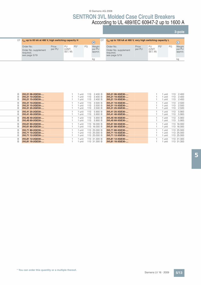
DT Icu up to 65 kA at 480 V, high switching capacity H DT Icu up to 100 kA at 480 V, very high switching capacity L
Order No. Price per PU
PU(UNIT, SET, M)
PS* PG Weight per PU approx.
Order No. Price per PU
PU(UNIT, SET, M)
PS* PG Weight per PU approx.
Order No. supplement required, see page 5/19
Order No. supplement required, see page 5/19
kg kg
B 3VL11 02-2KM30-.... 1 1 unit 113 2.000 --B 3VL11 25-2KM30-.... 1 1 unit 113 2.000 --B 3VL11 03-2KM30-.... 1 1 unit 113 2.000 --B 3VL11 35-2KM30-.... 1 1 unit 113 2.000 --B 3VL11 04-2KM30-.... 1 1 unit 113 2.000 --
B 3VL11 05-2KM30-.... 1 1 unit 113 2.000 --B 3VL11 06-2KM30-.... 1 1 unit 113 2.000 --B 3VL11 07-2KM30-.... 1 1 unit 113 2.000 --B 3VL11 08-2KM30-.... 1 1 unit 113 2.000 --B 3VL11 91-2KM30-.... 1 1 unit 113 2.000 --
B 3VL11 10-2KM30-.... 1 1 unit 113 2.000 --B 3VL11 12-2KM30-.... 1 1 unit 113 2.000 --B 3VL11 15-2KM30-.... 1 1 unit 113 2.000 --
B 3VL21 05-2KN30-.... 1 1 unit 113 2.200 B 3VL21 05-3KN30-.... 1 1 unit 113 2.200B 3VL21 06-2KN30-.... 1 1 unit 113 2.200 B 3VL21 06-3KN30-.... 1 1 unit 113 2.200B 3VL21 07-2KN30-.... 1 1 unit 113 2.200 B 3VL21 07-3KN30-.... 1 1 unit 113 2.200B 3VL21 08-2KN30-.... 1 1 unit 113 2.200 B 3VL21 08-3KN30-.... 1 1 unit 113 2.200B 3VL21 91-2KN30-.... 1 1 unit 113 2.200 B 3VL21 91-3KN30-.... 1 1 unit 113 2.200
B 3VL21 10-2KN30-.... 1 1 unit 113 2.200 B 3VL21 10-3KN30-.... 1 1 unit 113 2.200B 3VL21 11-2KN30-.... 1 1 unit 113 2.200 B 3VL21 11-3KN30-.... 1 1 unit 113 2.200B 3VL21 12-2KN30-.... 1 1 unit 113 2.200 B 3VL21 12-3KN30-.... 1 1 unit 113 2.200B 3VL21 15-2KN30-.... 1 1 unit 113 2.200 B 3VL21 15-3KN30-.... 1 1 unit 113 2.200
B 3VL31 10-2KN30-.... 1 1 unit 113 2.300 B 3VL31 10-3KN30-.... 1 1 unit 113 2.300B 3VL31 11-2KN30-.... 1 1 unit 113 2.300 B 3VL31 11-3KN30-.... 1 1 unit 113 2.300B 3VL31 12-2KN30-.... 1 1 unit 113 2.300 B 3VL31 12-3KN30-.... 1 1 unit 113 2.300B 3VL31 15-2KN30-.... 1 1 unit 113 2.300 B 3VL31 15-3KN30-.... 1 1 unit 113 2.300B 3VL31 17-2KN30-.... 1 1 unit 113 2.300 B 3VL31 17-3KN30-.... 1 1 unit 113 2.300
B 3VL31 20-2KN30-.... 1 1 unit 113 2.300 B 3VL31 20-3KN30-.... 1 1 unit 113 2.300B 3VL31 22-2KN30-.... 1 1 unit 113 2.300 B 3VL31 22-3KN30-.... 1 1 unit 113 2.300B 3VL31 25-2KN30-.... 1 1 unit 113 2.300 B 3VL31 25-3KN30-.... 1 1 unit 113 2.300
B 3VL41 25-2KN30-.... 1 1 unit 113 5.700 B 3VL41 25-3KN30-.... 1 1 unit 113 5.700B 3VL41 30-2KN30-.... 1 1 unit 113 5.700 B 3VL41 30-3KN30-.... 1 1 unit 113 5.700B 3VL41 35-2KN30-.... 1 1 unit 113 5.700 B 3VL41 35-3KN30-.... 1 1 unit 113 5.700B 3VL41 40-2KN30-.... 1 1 unit 113 5.700 B 3VL41 40-3KN30-.... 1 1 unit 113 5.700
B 3VL45 40-2KN30-.... 1 1 unit 113 5.700 B 3VL45 40-3KN30-.... 1 1 unit 113 5.700B 3VL45 50-2KN30-.... 1 1 unit 113 5.700 B 3VL45 50-3KN30-.... 1 1 unit 113 5.700B 3VL45 60-2KN30-.... 1 1 unit 113 5.700 B 3VL45 60-3KN30-.... 1 1 unit 113 5.700
B 3VL61 60-2KN30-.... 1 1 unit 113 14.000 B 3VL61 60-3KN30-.... 1 1 unit 113 14.000B 3VL61 70-2KN30-.... 1 1 unit 113 14.000 B 3VL61 70-3KN30-.... 1 1 unit 113 14.000B 3VL61 80-2KN30-.... 1 1 unit 113 14.000 B 3VL61 80-3KN30-.... 1 1 unit 113 14.000
B 3VL71 80-2KN30-.... 1 1 unit 113 21.800 B 3VL71 80-3KN30-.... 1 1 unit 113 21.800B 3VL71 90-2KN30-.... 1 1 unit 113 21.800 B 3VL71 90-3KN30-.... 1 1 unit 113 21.800B 3VL71 10-2KN30-.... 1 1 unit 113 21.800 B 3VL71 10-3KN30-.... 1 1 unit 113 21.800B 3VL71 12-2KN30-.... 1 1 unit 113 21.800 B 3VL71 12-3KN30-.... 1 1 unit 113 21.800
B 3VL81 12-2KN30-.... 1 1 unit 113 32.800 B 3VL81 12-3KN30-.... 1 1 unit 113 32.800B 3VL81 14-2KN30-.... 1 1 unit 113 32.800 B 3VL81 14-3KN30-.... 1 1 unit 113 32.800B 3VL81 16-2KN30-.... 1 1 unit 113 32.800 B 3VL81 16-3KN30-.... 1 1 unit 113 32.800
H L
* You can order this quantity or a multiple thereof.
© Siemens AG 2008

SENTRON 3VL Molded Case Circuit BreakersAccording to UL 489/IEC 60947-2 up to 1600 A
3-pole
5/10 Siemens LV 16 · 2009
5
1) UL recognized.2) Motor current according to NEC 430-110.3) Operation of the circuit breaker within the scope of UL 489/CSA is permitted only in conjunction with the mounting base (see page 5/40). 4) UL Code Classification Number.
Type Rated current In
Operating current of the instantaneous short-circuit releases "I" Ii
DT Icu up to 35 kA at 480 V, standard switching capacity N See "Overview".
Order No. Price per PU
PU(UNIT, SET, M)
PS* PG Weight per PU approx.
Order No. supplement required, see page 5/19
A A kg
Fixed-mounted circuit breakers, VL150 UL (DG frame) to VL1600 UL (PG frame), magnetic and electronic trip units
Circuit breakers for starter combination, I function (motor circuit protector; UL file: E10848, CCN4): DKPUZ)1)
Without overload release, with adjustable short-circuit releases
Connection type: Circuit breakers without preassembled terminals, terminals must be ordered under "Accessories", "Plug-in versions/withdrawable versions", pages 5/29 to 5/35 and under "Accessories", "Connection methods for fixed-mounted circuit breakers", pages 5/35 to 5/40.
VL150 UL, DG frame 150 450- 900 -- 150 750-1500 -- 150 1250-2500 --
VL250 UL, FG frame 250 600-1200 -- 250 1000-2000 -- 250 1750-3500 --
VL400 UL, JG frame 400 1250-2500 -- 4002) 2000-4000 --
VL400X UL, LG frame 600 2000-4000 -- 6002) 2750-5500 --
VL800 UL, MG frame 800 3250-6500 --
VL1200 UL, NG frame 1200 7000-12000 --
Molded case switches (UL file: E68312, CCN4): WJAZ)
Without overload release, with permanently set short-circuit releases (for intrinsic protection only)
Connection type: Circuit breakers without preassembled terminals, terminals must be ordered under "Accessories", "Plug-in versions/withdrawable versions", pages 5/29 to 5/35 and under "Accessories", "Connection methods for fixed-mounted circuit breakers", pages 5/35 to 5/40.
VL150X UL, CG frame 100 1800 B 3VL11 10-1KE30-.... 1 1 unit 113 2.000 150 1800 B 3VL11 15-1KE30-.... 1 1 unit 113 2.000
VL150 UL, DG frame 150 2500 --
VL250 UL, FG frame 250 3500 --
VL400 UL, JG frame 400 4400 --
VL400X UL, LG frame 600 5500 --
VL800 UL, MG frame 800 6500 --
VL1200 UL, NG frame 1200 12000 --
VL1600 UL, PG frame3) 1600 14000 --
N
NSE0_00707
NSE0_00708
* You can order this quantity or a multiple thereof.
© Siemens AG 2008

SENTRON 3VL Molded Case Circuit BreakersAccording to UL 489/IEC 60947-2 up to 1600 A
3-pole
5/11Siemens LV 16 · 2009
5
DT Icu up to 65 kA at 480 V, high switching capacity H DT Icu up to 100 kA at 480 V, very high switching capacity L
Order No. Price per PU
PU(UNIT, SET, M)
PS* PG Weight per PU approx.
Order No. Price per PU
PU(UNIT, SET, M)
PS* PG Weight per PU approx.
Order No. supplement required, see page 5/19
Order No. supplement required, see page 5/19
kg kg
B 3VL21 15-2KJ30-.... 1 1 unit 113 2.200 --B 3VL21 15-2KK30-.... 1 1 unit 113 2.200 --B 3VL21 15-2KL30-.... 1 1 unit 113 2.200 --
B 3VL31 25-2KJ30-.... 1 1 unit 113 2.300 --B 3VL31 25-2KK30-.... 1 1 unit 113 2.300 --B 3VL31 25-2KL30-.... 1 1 unit 113 2.300 --
B 3VL41 40-2KJ30-.... 1 1 unit 113 5.700 --B 3VL41 40-2KK30-.... 1 1 unit 113 5.700 --
B 3VL45 60-2KJ30-.... 1 1 unit 113 5.700 --B 3VL45 60-2KK30-.... 1 1 unit 113 5.700 --
B 3VL61 80-2KK30-.... 1 1 unit 113 14.000 --
B 3VL71 12-2KK30-.... 1 1 unit 113 21.800 --
B 3VL11 10-2KE30-.... 1 1 unit 113 2.000 --B 3VL11 15-2KE30-.... 1 1 unit 113 2.000 --
B 3VL21 15-2KE30-.... 1 1 unit 113 2.200 B 3VL21 15-3KE30-.... 1 1 unit 113 2.200
B 3VL31 25-2KE30-.... 1 1 unit 113 2.300 B 3VL31 25-3KE30-.... 1 1 unit 113 2.300
B 3VL41 40-2KE30-.... 1 1 unit 113 5.700 B 3VL41 40-3KE30-.... 1 1 unit 113 5.700
B 3VL45 60-2KE30-.... 1 1 unit 113 5.700 B 3VL45 60-3KE30-.... 1 1 unit 113 5.700
B 3VL61 80-2KE30-.... 1 1 unit 113 15.700 B 3VL61 80-3KE30-.... 1 1 unit 113 15.700
B 3VL71 12-2KE30-.... 1 1 unit 113 23.500 B 3VL71 12-3KE30-.... 1 1 unit 113 23.500
B 3VL81 16-2KE30-.... 1 1 unit 113 29.800 B 3VL81 16-3KE30-.... 1 1 unit 113 29.800
H L
* You can order this quantity or a multiple thereof.
© Siemens AG 2008

SENTRON 3VL Molded Case Circuit BreakersAccording to UL 489/IEC 60947-2 up to 1600 A
3-pole
5/12 Siemens LV 16 · 2009
5
L = Overload
S = Short-circuit protection, short-time delayed
I = Short-circuit protection, instantaneous
1) Operation of the circuit breaker within the scope of UL 489/CSA is permitted only in conjunction with the mounting base (see page 5/40).
Type Rated current In
Current setting of the inverse-time delayed overload trip unit "L"IR
Operating current of the instantaneous short-circuit releases "I" Ii
S function (short-time delayed short-circuit releases) Isd
DT Icu up to 35 kA at 480 V, standard switching capacity N See "Overview".
Order No. Price per PU
PU(UNIT, SET, M)
PS* PG Weight per PU approx.
Order No. supplement required, see page 5/19
A A A A kg
Fixed-mounted circuit breakers, VL150 UL (DG frame) to VL1600 UL (PG frame), electronic trip units (UL file: E10848)
System and generator protection
With electronic trip unit ETU (model 545) LSI function (tsd = 0 to 0.5 s)
Connection type: Circuit breakers without preassembled terminals, terminals must be ordered under "Accessories", "Plug-in versions/withdrawable versions", pages 5/29 to 5/35 and under "Accessories", "Connection methods for fixed-mounted circuit breakers", pages 5/35 to 5/40.
VL150 UL, DG frame 60 30- 60 11 x In 1.5 - 10 x IR B 3VL21 06-1GE30-.... 1 1 unit 113 2.400 100 40- 100 11 x In 1.5 - 10 x IR B 3VL21 10-1GE30-.... 1 1 unit 113 2.400 150 60- 150 11 x In 1.5 - 10 x IR B 3VL21 15-1GE30-.... 1 1 unit 113 2.400
VL250 UL, FG frame 100 40- 100 11 x In 1.5 - 10 x IR B 3VL31 10-1GE30-.... 1 1 unit 113 2.500 150 60- 150 11 x In 1.5 - 10 x IR B 3VL31 15-1GE30-.... 1 1 unit 113 2.500 250 70- 250 11 x In 1.5 - 10 x IR B 3VL31 25-1GE30-.... 1 1 unit 113 2.500
VL400 UL, JG frame 250 70- 250 11 x In 1.5 - 10 x IR B 3VL41 25-1GE30-.... 1 1 unit 113 5.900 400 150- 400 11 x In 1.5 - 10 x IR B 3VL41 40-1GE30-.... 1 1 unit 113 5.900
VL400X UL, LG frame 400 150- 400 11 x In 1.5 - 10 x IR B 3VL45 40-1GE30-.... 1 1 unit 113 5.900 600 200- 600 10 x In 1.5 - 9 x IR B 3VL45 60-1GE30-.... 1 1 unit 113 5.900
VL800 UL, MG frame 600 200- 600 10 x In 1.5 - 9 x IR B 3VL61 60-1GE30-.... 1 1 unit 113 16.000 800 300- 800 8 x In 1.5 - 7 x IR B 3VL61 80-1GE30-.... 1 1 unit 113 16.000
VL1200 UL, NG frame 800 300- 800 11 x In 1.5 - 10 x IR B 3VL71 80-1GE30-.... 1 1 unit 113 25.0001000 400-1000 11 x In 1.5 - 10 x IR B 3VL71 10-1GE30-.... 1 1 unit 113 25.0001200 400-1200 10 x In 1.5 - 10 x IR B 3VL71 12-1GE30-.... 1 1 unit 113 25.000
VL1600 UL, PG frame1) 1200 400-1200 10 x In 1.5 - 10 x IR B 3VL81 12-1GE30-.... 1 1 unit 113 31.3001600 700-1600 6 x In 1.5 - 8 x IR B 3VL81 16-1GE30-.... 1 1 unit 113 31.300
N
L
S
I
NSE0_00692
* You can order this quantity or a multiple thereof.
© Siemens AG 2008
SENTRON 3VL Molded Case Circuit BreakersAccording to UL 489/IEC 60947-2 up to 1600 A
3-pole
5/13Siemens LV 16 · 2009
5
DT Icu up to 65 kA at 480 V, high switching capacity H DT Icu up to 100 kA at 480 V, very high switching capacity L
Order No. Price per PU
PU(UNIT, SET, M)
PS* PG Weight per PU approx.
Order No. Price per PU
PU(UNIT, SET, M)
PS* PG Weight per PU approx.
Order No. supplement required, see page 5/19
Order No. supplement required, see page 5/19
kg kg
B 3VL21 06-2GE30-.... 1 1 unit 113 2.400 B 3VL21 06-3GE30-.... 1 1 unit 113 2.400B 3VL21 10-2GE30-.... 1 1 unit 113 2.400 B 3VL21 10-3GE30-.... 1 1 unit 113 2.400B 3VL21 15-2GE30-.... 1 1 unit 113 2.400 B 3VL21 15-3GE30-.... 1 1 unit 113 2.400
B 3VL31 10-2GE30-.... 1 1 unit 113 2.500 B 3VL31 10-3GE30-.... 1 1 unit 113 2.500B 3VL31 15-2GE30-.... 1 1 unit 113 2.500 B 3VL31 15-3GE30-.... 1 1 unit 113 2.500B 3VL31 25-2GE30-.... 1 1 unit 113 2.500 B 3VL31 25-3GE30-.... 1 1 unit 113 2.500
B 3VL41 25-2GE30-.... 1 1 unit 113 5.900 B 3VL41 25-3GE30-.... 1 1 unit 113 5.900B 3VL41 40-2GE30-.... 1 1 unit 113 5.900 B 3VL41 40-3GE30-.... 1 1 unit 113 5.900
B 3VL45 40-2GE30-.... 1 1 unit 113 5.900 B 3VL45 40-3GE30-.... 1 1 unit 113 5.900B 3VL45 60-2GE30-.... 1 1 unit 113 5.900 B 3VL45 60-3GE30-.... 1 1 unit 113 5.900
B 3VL61 60-2GE30-.... 1 1 unit 113 16.000 B 3VL61 60-3GE30-.... 1 1 unit 113 16.000B 3VL61 80-2GE30-.... 1 1 unit 113 16.000 B 3VL61 80-3GE30-.... 1 1 unit 113 16.000
B 3VL71 80-2GE30-.... 1 1 unit 113 25.000 B 3VL71 80-3GE30-.... 1 1 unit 113 25.000B 3VL71 10-2GE30-.... 1 1 unit 113 25.000 B 3VL71 10-3GE30-.... 1 1 unit 113 25.000B 3VL71 12-2GE30-.... 1 1 unit 113 25.000 B 3VL71 12-3GE30-.... 1 1 unit 113 25.000
B 3VL81 12-2GE30-.... 1 1 unit 113 31.300 B 3VL81 12-3GE30-.... 1 1 unit 113 31.300B 3VL81 16-2GE30-.... 1 1 unit 113 31.300 B 3VL81 16-3GE30-.... 1 1 unit 113 31.300
H L
* You can order this quantity or a multiple thereof.
© Siemens AG 2008

SENTRON 3VL Molded Case Circuit BreakersAccording to UL 489/IEC 60947-2 up to 1600 A
3-pole
5/14 Siemens LV 16 · 2009
5
L = Overload
S = Short-circuit protection, short-time delayed
I = Short-circuit protection, instantaneous
G = Ground-fault protection
1) Operation of the circuit breaker within the scope of UL 489/CSA is permitted only in conjunction with the mounting base (see page 5/40).
2) Vectorial summation current formation for the currents.
Type Rated current In
Current setting of the inverse-time delayed overload release "L"IR
DT Icu up to 35 kA at 480 V, standard switching capacity NSee "Overview".
Order No. Price see page 5/18
PU(UNIT, SET, M)
PS* PG Weight per PU approx.
Order No. supplement required, see page 5/19
A A kg
Fixed-mounted circuit breakers, VL150 UL (DG frame) to VL1600 UL (PG frame), up to 1600 A, electronic trip units (UL file: E10848)
Circuit breakers with electronic trip unit ETU
Connection type: Circuit breakers without preassembled terminals, terminals must be ordered under "Accessories", "Plug-in versions/withdrawable versions", pages 5/29 to 5/35 and under "Accessories", "Connection methods for fixed-mounted circuit breakers", pages 5/35 to 5/40.
VL150 UL, 60 30- 60 B 3VL21 06-1@@30-.... 1 1 unit 113 2.400
DG frame 100 40- 100 B 3VL21 10-1@@30-.... 1 1 unit 113 2.400
150 60- 150 B 3VL21 15-1@@30-.... 1 1 unit 113 2.400
VL250 UL, 100 40- 100 B 3VL31 10-1@@30-.... 1 1 unit 113 2.500
FG frame 150 60- 150 B 3VL31 15-1@@30-.... 1 1 unit 113 2.500
250 70- 250 B 3VL31 25-1@@30-.... 1 1 unit 113 2.500
VL400 UL, 250 70- 250 B 3VL41 25-1@@30-.... 1 1 unit 113 5.900
JG frame 400 150- 400 B 3VL41 40-1@@30-.... 1 1 unit 113 5.900
VL400X UL, 400 150- 400 B 3VL45 40-1@@30-.... 1 1 unit 113 9.300
LG frame 600 200- 600 B 3VL45 60-1@@30-.... 1 1 unit 113 9.300
VL800 UL, 600 200- 600 B 3VL61 60-1@@30-.... 1 1 unit 113 16.000
MG frame 800 300- 800 B 3VL61 80-1@@30-.... 1 1 unit 113 16.000
VL1200 UL, 800 300- 800 B 3VL71 80-1@@30-.... 1 1 unit 113 25.000
NG frame 1000 400-1000 B 3VL71 10-1@@30-.... 1 1 unit 113 25.000
1200 400-1200 B 3VL71 12-1@@30-.... 1 1 unit 113 25.000
VL1600 UL, 1200 400-1200 B 3VL81 12-1@@30-.... 1 1 unit 113 31.300
PG frame1) 1600 700-1600 B 3VL81 16-1@@30-.... 1 1 unit 113 31.300
ETU trip units, 3-pole versionOrder No. supple-ments
System protection with LI function G B
System protection with LIG functionFor 4-wire three-phase systems2) G D
System and generator protection with LSI function G E
System and generator protection with LSIG functionFor 4-wire three-phase systems2) G H
N
NSE0_00943
L
I
L
IG
NSE0_00693
L
S
I
NSE0_00692
L
S
IG
NSE0_00694
* You can order this quantity or a multiple thereof.
© Siemens AG 2008

SENTRON 3VL Molded Case Circuit BreakersAccording to UL 489/IEC 60947-2 up to 1600 A
3-pole
5/15Siemens LV 16 · 2009
5
DT Icu up to 65 kA at 480 V, high switching capacity H
DT Icu up to 100 kA at 480 V, very high switching capacity L
Order No. Price see page 5/18
PU(UNIT, SET, M)
PS* PG Weight per PU approx.
Order No. Price see page 5/18
PU(UNIT, SET, M)
PS* PG Weight per PU approx.
Order No. supplement required, see page 5/19
Order No. supplement required, see page 5/19
kg kg
B 3VL21 06-2@@30-.... 1 1 unit 113 2.400 B 3VL21 06-3@@30-.... 1 1 unit 113 2.400
B 3VL21 10-2@@30-.... 1 1 unit 113 2.400 B 3VL21 10-3@@30-.... 1 1 unit 113 2.400
B 3VL21 15-2@@30-.... 1 1 unit 113 2.400 B 3VL21 15-3@@30-.... 1 1 unit 113 2.400
B 3VL31 10-2@@30-.... 1 1 unit 113 2.500 B 3VL31 10-3@@30-.... 1 1 unit 113 2.500
B 3VL31 15-2@@30-.... 1 1 unit 113 2.500 B 3VL31 15-3@@30-.... 1 1 unit 113 2.500
B 3VL31 25-2@@30-.... 1 1 unit 113 2.500 B 3VL31 25-3@@30-.... 1 1 unit 113 2.500
B 3VL41 25-2@@30-.... 1 1 unit 113 5.900 B 3VL41 25-3@@30-.... 1 1 unit 113 5.900
B 3VL41 40-2@@30-.... 1 1 unit 113 5.900 B 3VL41 40-3@@30-.... 1 1 unit 113 5.900
B 3VL45 40-2@@30-.... 1 1 unit 113 9.300 B 3VL45 40-3@@30-.... 1 1 unit 113 9.300
B 3VL45 60-2@@30-.... 1 1 unit 113 9.300 B 3VL45 60-3@@30-.... 1 1 unit 113 9.300
B 3VL61 60-2@@30-.... 1 1 unit 113 16.000 B 3VL61 60-3@@30-.... 1 1 unit 113 16.000
B 3VL61 80-2@@30-.... 1 1 unit 113 16.000 B 3VL61 80-3@@30-.... 1 1 unit 113 16.000
B 3VL71 80-2@@30-.... 1 1 unit 113 25.000 B 3VL71 80-3@@30-.... 1 1 unit 113 25.000
B 3VL71 10-2@@30-.... 1 1 unit 113 25.000 B 3VL71 10-3@@30-.... 1 1 unit 113 25.000
B 3VL71 12-2@@30-.... 1 1 unit 113 25.000 B 3VL71 12-3@@30-.... 1 1 unit 113 25.000
B 3VL81 12-2@@30-.... 1 1 unit 113 31.300 B 3VL81 12-3@@30-.... 1 1 unit 113 31.300
B 3VL81 16-2@@30-.... 1 1 unit 113 31.300 B 3VL81 16-3@@30-.... 1 1 unit 113 31.300
Order No. supple-ments
Order No. supple-ments
G B G B
G D
G D
G E
G E
G H
G H
H L
* You can order this quantity or a multiple thereof.
© Siemens AG 2008

SENTRON 3VL Molded Case Circuit BreakersAccording to UL 489/IEC 60947-2 up to 1600 A
3-pole
5/16 Siemens LV 16 · 2009
5
L = Overload
S = Short-circuit protection, short-time delayed
I = Short-circuit protection, instantaneous
G = Ground-fault protection
1) Operation of the circuit breaker within the scope of UL 489/CSA is permitted only in conjunction with the mounting base (see page 5/40).
2) External current transformer required in addition (on request).3) Vectorial summation current formation for the currents.
Type Rated current In
Current setting of the inverse-time delayed overload release "L"IR
DT Icu up to 35 kA at 480 V, standard switching capacity N See "Overview".
Order No. Price see page 5/18
PU(UNIT, SET, M)
PS* PG Weight per PU approx.
Order No. supplement required, see page 5/19
A A kg
Fixed-mounted circuit breakers, VL150 UL (DG frame) to VL1600 UL (PG frame), up to 1600 A, electronic trip units (UL file: E10848)
Circuit breakers with electronic trip unit ETU
Connection type: Circuit breakers without preassembled terminals, terminals must be ordered under "Accessories", "Plug-in versions/withdrawable versions", pages 5/29 to 5/35 and under "Accessories", "Connection methods for fixed-mounted circuit breakers", pages 5/35 to 5/40.
VL150 UL, 60 30- 60 B 3VL21 06-1@@30-.... 1 1 unit 113 2.400
DG frame 100 40- 100 B 3VL21 10-1@@30-.... 1 1 unit 113 2.400
150 60- 150 B 3VL21 15-1@@30-.... 1 1 unit 113 2.400
VL250 UL, 100 40- 100 B 3VL31 10-1@@30-.... 1 1 unit 113 2.500
FG frame 150 60- 150 B 3VL31 15-1@@30-.... 1 1 unit 113 2.500
250 70- 250 B 3VL31 25-1@@30-.... 1 1 unit 113 2.500
VL400 UL, 250 70- 250 B 3VL41 25-1@@30-.... 1 1 unit 113 5.900
JG frame 400 150- 400 B 3VL41 40-1@@30-.... 1 1 unit 113 5.900
VL400X UL, 400 150- 400 B 3VL45 40-1@@30-.... 1 1 unit 113 9.300
LG frame 600 200- 600 B 3VL45 60-1@@30-.... 1 1 unit 113 9.300
VL800 UL, 600 200- 600 B 3VL61 60-1@@30-.... 1 1 unit 113 16.000
MG frame 800 300- 800 B 3VL61 80-1@@30-.... 1 1 unit 113 16.000
VL1200 UL, 800 300- 800 B 3VL71 80-1@@30-.... 1 1 unit 113 25.000
NG frame 1000 400-1000 B 3VL71 10-1@@30-.... 1 1 unit 113 25.000
1200 400-1200 B 3VL71 12-1@@30-.... 1 1 unit 113 25.000
VL1600 UL, 1200 400-1200 B 3VL81 12-1@@30-.... 1 1 unit 113 31.300
PG frame1) 1600 700-1600 B 3VL81 16-1@@30-.... 1 1 unit 113 31.300
Order No. supple-ments
LCD ETU trip unit, 3-pole version
System protection with LI/LS/LSI function J H
System protection with LSIG function
For 4-wire three-phase systems2) 3) J M
N
L
S
I
NSE0_00696
L
S
IG
NSE0_00697
* You can order this quantity or a multiple thereof.
© Siemens AG 2008

SENTRON 3VL Molded Case Circuit BreakersAccording to UL 489/IEC 60947-2 up to 1600 A
3-pole
5/17Siemens LV 16 · 2009
5
.
DT Icu up to 65 kA at 480 V, high switching capacity H
DT Icu up to 100 kA at 480 V, very high switching capacity L
Order No. Price see page 5/18
PU(UNIT, SET, M)
PS* PG Weight per PU approx.
Order No. Price see page 5/18
PU(UNIT, SET, M)
PS* PG Weight per PU approx.
Order No. supplement required, see page 5/19
Order No. supplement required, see page 5/19
kg kg
B 3VL21 06-2@@30-.... 1 1 unit 113 2.400 B 3VL21 06-3@@30-.... 1 1 unit 113 2.400
B 3VL21 10-2@@30-.... 1 1 unit 113 2.400 B 3VL21 10-3@@30-.... 1 1 unit 113 2.400
B 3VL21 15-2@@30-.... 1 1 unit 113 2.400 B 3VL21 15-3@@30-.... 1 1 unit 113 2.400
B 3VL31 10-2@@30-.... 1 1 unit 113 2.500 B 3VL31 10-3@@30-.... 1 1 unit 113 2.500
B 3VL31 15-2@@30-.... 1 1 unit 113 2.500 B 3VL31 15-3@@30-.... 1 1 unit 113 2.500
B 3VL31 25-2@@30-.... 1 1 unit 113 2.500 B 3VL31 25-3@@30-.... 1 1 unit 113 2.500
B 3VL41 25-2@@30-.... 1 1 unit 113 5.900 B 3VL41 25-3@@30-.... 1 1 unit 113 5.900
B 3VL41 40-2@@30-.... 1 1 unit 113 5.900 B 3VL41 40-3@@30-.... 1 1 unit 113 5.900
B 3VL45 40-2@@30-.... 1 1 unit 113 9.300 B 3VL45 40-3@@30-.... 1 1 unit 113 9.300
B 3VL45 60-2@@30-.... 1 1 unit 113 9.300 B 3VL45 60-3@@30-.... 1 1 unit 113 9.300
B 3VL61 60-2@@30-.... 1 1 unit 113 16.000 B 3VL61 60-3@@30-.... 1 1 unit 113 16.000
B 3VL61 80-2@@30-.... 1 1 unit 113 16.000 B 3VL61 80-3@@30-.... 1 1 unit 113 16.000
B 3VL71 80-2@@30-.... 1 1 unit 113 25.000 B 3VL71 80-3@@30-.... 1 1 unit 113 25.000
B 3VL71 10-2@@30-.... 1 1 unit 113 25.000 B 3VL71 10-3@@30-.... 1 1 unit 113 25.000
B 3VL71 12-2@@30-.... 1 1 unit 113 25.000 B 3VL71 12-3@@30-.... 1 1 unit 113 25.000
B 3VL81 12-2@@30-.... 1 1 unit 113 31.300 B 3VL81 12-3@@30-.... 1 1 unit 113 31.300
B 3VL81 16-2@@30-.... 1 1 unit 113 31.300 B 3VL81 16-3@@30-.... 1 1 unit 113 31.300
Order No. supple-ments
Order No. supple-ments
J H
J H
J M J M
H L
* You can order this quantity or a multiple thereof.
© Siemens AG 2008
SENTRON 3VL Molded Case Circuit BreakersAccording to UL 489/IEC 60947-2 up to 1600 A
3-pole
5/18 Siemens LV 16 · 2009
5
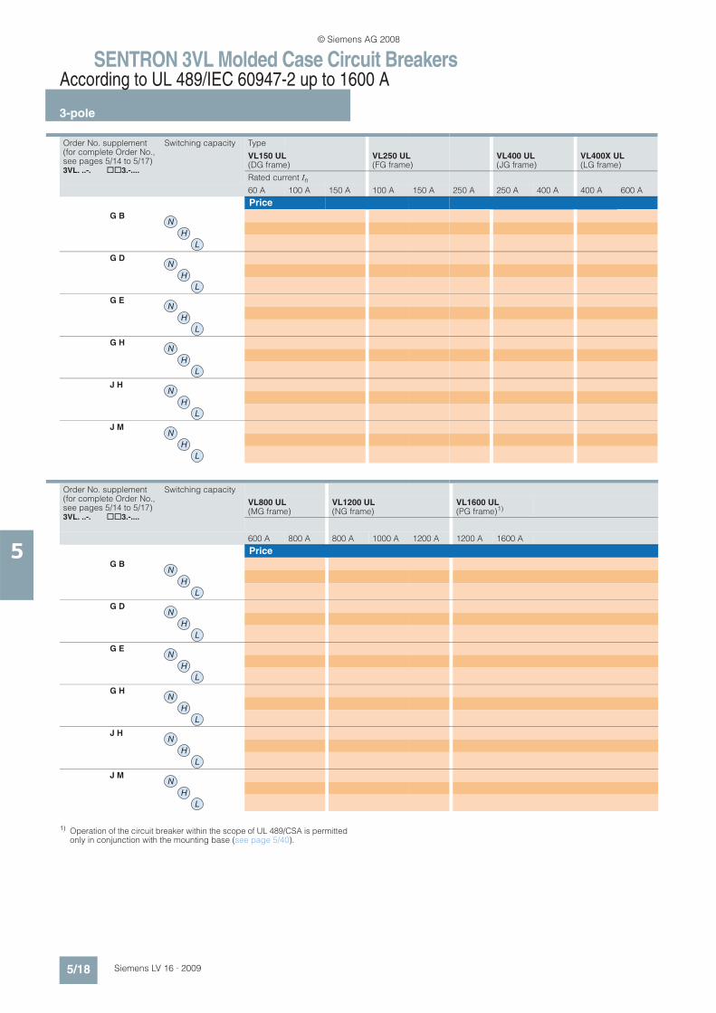
1) Operation of the circuit breaker within the scope of UL 489/CSA is permitted only in conjunction with the mounting base (see page 5/40).
Order No. supplement (for complete Order No., see pages 5/14 to 5/17) 3VL. ..-. @@3.-....
Switching capacity Type
VL150 UL (DG frame)
VL250 UL (FG frame)
VL400 UL (JG frame)
VL400X UL (LG frame)
Rated current In
60 A 100 A 150 A 100 A 150 A 250 A 250 A 400 A 400 A 600 A
Price
G B
G D
G E
G H
J H
J M
N
H
L
N
H
L
N
H
L
N
H
L
N
H
L
N
H
L
Order No. supplement (for complete Order No., see pages 5/14 to 5/17) 3VL. ..-. @@3.-....
Switching capacity
VL800 UL (MG frame)
VL1200 UL (NG frame)
VL1600 UL (PG frame)1)
600 A 800 A 800 A 1000 A 1200 A 1200 A 1600 A
Price
G B
G D
G E
G H
J H
J M
N
H
L
N
H
L
N
H
L
N
H
L
N
H
L
N
H
L
© Siemens AG 2008

SENTRON 3VL Molded Case Circuit BreakersAccording to UL 489/IEC 60947-2 up to 1600 A
Options
5/19Siemens LV 16 · 2009
5
n Selection and ordering data
x = additional price
-- Not available1) For SENTRON VL150 UL (DG frame)/VL250 UL (FG frame) circuit breakers
with solid-state overcurrent trip units, the only option is one undervoltage release or shunt trip unit, or one auxiliary/alarm switch combination.
2) Except for mounting in the left accessory sub-section of the SENTRON VL150 UL (DG frame)/VL250 UL (FG frame) circuit breakers with solid-state overcurrent trip units, since this sub-section is occupied by the tripping solenoid. Only one auxiliary trip unit or one auxiliary/alarm switchcombination can be installed on the right-hand side.
3) With mounting adapter up to 3 HS.4) With mounting adapter up to 2 HS + 2 AS.
1. Order No. supplement: Undervoltage releases or shunt trip units, wiring directly to accessories
Rated control supply voltage Us/frequency
Order No. supplement Circuit breakers
Type
AC 50/60 HzDC
3VL . . . . - . . . . . - @ @.. VL150X UL (CG frame) to VL400X UL (LG frame)1)
Additional price
VL800 UL (MG frame) to VL1600 UL (PG frame)
Additional price
Without auxiliary trip units 0 A None None
With undervoltage releases Only right pole
V AC V DC
-- 12 2 N x 1) x-- 24 2 P x 1) x-- 48 2 U x 1) x
-- 60 2 V x 1) x-- 110-127 2 R x 1) x-- 220-250 2 S x 1) x
24 -- 2 D x 1) x110-127 -- 2 G x 1) x220-250 -- 2 H x 1) x
208 -- 2 M x 1) x277 -- 2 Q x 1) x
380-415 -- 2 J x 1) x440-480 -- 2 K x 1) x500-525 -- 2 L x 1) x
With shunt trip units Only right pole
V AC V DC
24 24 8 C x 1) x-- 48-60 8 J x 1) x-- 110-127 8 K x 1) x-- 220-250 8 Q x 1) x
48-60 -- 8 M x 1) x110-127 -- 8 R x 1) x208-277 -- 8 T x 1) x380-600 -- 8 V x 1) x
2. Order No. supplement: Auxiliary switches (HS) and alarm switches (AS), left/right pole, directly wired to accessories
Equipment Order No. supplement Circuit breakers
Type
HS = 1 NO or 1 NC switching blockAS = 1 NO switching block
3VL . . . . - . . . . . -. . @ @VL150X UL (CG frame) to VL400X UL (LG frame)Additional price
VL800 UL (MG frame) to VL1600 UL (PG frame)Additional price
Without auxiliary/alarm switches A 0 None None
2 HS (1 NO/1 NC)3) B 1 x 2) --4 HS (2 NO/2 NC) C 1 -- x2 HS (1 NO/1 NC) + 1 AS (1 NO) D 1 x 2) --2 HS (1 NO/1 NC) + 1 AS (1 NO)4) E 1 -- x
© Siemens AG 2008

SENTRON 3VL Molded Case Circuit BreakersAccording to UL 489/IEC 60947-2 up to 1600 A
Options
5/20 Siemens LV 16 · 2009
5
x = additional price
When ordering, add "-Z" to the complete Order No. and add the relevant order code(s).
Order No. with "–Z"1 2 3 4 5 6 7 8 9 10 11 12 13 14 15 16
3VL . . . . – . . . . . – . . . . –Zand additional order code(s)
@ @ @ + . . . + . . .
Additional price
Code for further versions –Z
For fixed-mounted circuit breakers (wired in factory)
Wiring for internal accessories(Auxiliary switches, alarm switches, auxiliary trip units not included in scope of supply)with connecting cables (3 m long) brought out at the rear
VL150X UL (CG frame) to VL1600 UL (PG frame)
L 0 2 x
Wiring for motorized operating mechanisms(Motorized operating mechanism not included in the scope of supply,to order see pages 5/24 to 5/28) with connecting cables (3 m long), brought out at the top on VL150X UL (CG frame) to VL400X UL (LG frame) or brought out at the right on VL800 UL (MG frame) to VL1600 UL (PG frame)
VL150X UL (CG frame) to VL1600 UL (PG frame)
L 1 2 x
Motorized operating mechanisms (24 V DC)Mounted on the circuit breaker(motorized operating mechanism included in scope of supply) With wiring for internal accessories of the circuit breaker with connecting cables (3 m long) brought out at the rear, (auxiliary switches, alarm switches, auxiliary trip units not included in scope of supply)
VL150X UL (CG frame) to VL250 UL (FG frame)
VL400 UL (JG frame) to VL400X UL (LG frame)
VL800 UL (MG frame)
VL1200 UL (NG frame) to VL1600 UL (PG frame)
M 2 4 x
x
x
x
Motorized operating mechanisms (42-48 V AC/DC)Mounted on the circuit breaker(motorized operating mechanism included in scope of supply) With wiring for internal accessories of the circuit breaker with connecting cables (3 m long) brought out at the rear, (auxiliary switches, alarm switches, auxiliary trip units not included in scope of supply)
VL150X UL (CG frame) to VL250 UL (FG frame)
VL400 UL (JG frame) to VL400X UL (LG frame)
VL800 UL (MG frame)
VL1200 UL (NG frame) to VL1600 UL (PG frame)
M 4 2 x
x
x
x
Motorized operating mechanisms
(60 V AC/DC)Mounted on the circuit breaker(motorized operating mechanism included in scope of supply) With wiring for internal accessories of the circuit breaker with connecting cables (3 m long) brought out at the rear, (auxiliary switches, alarm switches, auxiliary trip units not included in scope of supply)
VL150X UL (CG frame) to VL250 UL (FG frame)
VL400 UL (JG frame) to VL400X UL (LG frame)
VL800 UL (MG frame)
VL1200 UL (NG frame) to VL1600 UL (PG frame)
M 6 0 x
x
x
x
Motorized operating mechanisms (110-127 V AC/DC)Mounted on the circuit breaker(motorized operating mechanism included in scope of supply) With wiring for internal accessories of the circuit breaker with connecting cables (3 m long) brought out at the rear, (auxiliary switches, alarm switches, auxiliary trip units not included in scope of supply)
VL150X UL (CG frame) to VL250 UL (FG frame)
VL400 UL (JG frame) to VL400X UL (LG frame)
VL800 UL (MG frame)
VL1200 UL (NG frame) to VL1600 UL (PG frame)
M 1 1 x
x
x
x
Motorized operating mechanisms (220-250 V AC/DC)Mounted on the circuit breaker(motorized operating mechanism included in scope of supply) With wiring for internal accessories of the circuit breaker with connecting cables (3 m long) brought out at the rear, (auxiliary switches, alarm switches, auxiliary trip units not included in scope of supply)
VL150X UL (CG frame) to VL250 UL (FG frame)
VL400 UL (JG frame) to VL400X UL (LG frame)
VL800 UL (MG frame)
VL1200 UL (NG frame) to VL1600 UL (PG frame)
M 2 2 x
x
x
x
© Siemens AG 2008

SENTRON 3VL Molded Case Circuit BreakersAccording to UL 489/IEC 60947-2 up to 1600 A
Accessories and spare parts
5/21Siemens LV 16 · 2009
5
n Selection and ordering data
1) Except for mounting in the left accessory sub-section of the SENTRON VL150 UL (DG frame)/VL250 UL (FG frame) circuit breakers with solid-state overcurrent trip units, since this sub-section is occupied by the tripping solenoid.
2) Shunt trip unit with disconnection contact (3SB3 for ON/OFF position) non-floating (see "Schematics").
3) For VL400 UL (JG frame)/VL400X UL (LG frame): Unsuitable for mounting in the right-hand accessory sub-section. The 3VL9 400-2AB01 assembly kit with auxiliary switches only is recommended.
Wiring directly at accessories DT For VL150X UL (CG frame) to VL400X UL (LG frame)
PU(UNIT, SET, M)
PS* PG Weight per PU approx.Order No. Price
per PU
kg
Auxiliary switches and auxiliary trip units (UL file: E69455)
3-pole
Auxiliary switches (HS) and alarm switches (AS)For retrofitting
Assembly kits Mounting side
2 HS (1 NO + 1 NC) N, left1), right B 3VL9 400-2AB01 1 1 unit 113 0.027
4 HS (2 NO + 2 NC) N, left, right --
2 HS (1 NC + 1 NO) Left, right3) B 3VL9 400-2AD01 1 1 unit 113 0.051
+ 1 AS (1 NO) (assembly kit) Left --
Additional auxiliary switch/alarm switch combinations See page 5/23.
3VL9 400-2A.01 Shunt trip units2)
For retrofitting
V AC V DC Mounting side
24 24 Right pole only B 3VL9 400-1SC01 1 1 unit 113 0.075-- 48-60 Right pole only B 3VL9 400-1SJ01 1 1 unit 113 0.075
-- 110-127 Right pole only B 3VL9 400-1SK01 1 1 unit 113 0.075-- 220-250 Right pole only B 3VL9 400-1SQ01 1 1 unit 113 0.07548-60 -- Right pole only B 3VL9 400-1SM01 1 1 unit 113 0.075
110-127 -- Right pole only B 3VL9 400-1SR01 1 1 unit 113 0.075208-277 -- Right pole only B 3VL9 400-1ST01 1 1 unit 113 0.075380-600 -- Right pole only B 3VL9 400-1SV01 1 1 unit 113 0.075
Undervoltage releasesFor retrofitting
V AC V DC Mounting side
-- 12 Right pole only B 3VL9 400-1UN01 1 1 unit 113 0.075-- 24 Right pole only B 3VL9 400-1UP01 1 1 unit 113 0.075-- 48 Right pole only B 3VL9 400-1UU01 1 1 unit 113 0.075-- 60 Right pole only B 3VL9 400-1UV01 1 1 unit 113 0.075
3VL9 400-1S.01, 24 -- Right pole only B 3VL9 400-1UD01 1 1 unit 113 0.0753VL9 400 1U.01 110-127 -- Right pole only B 3VL9 400-1UG01 1 1 unit 113 0.075
-- 110-127 Right pole only B 3VL9 400-1UR01 1 1 unit 113 0.075208 -- Right pole only B 3VL9 400-1UM01 1 1 unit 113 0.075
220-250 -- Right pole only B 3VL9 400-1UH01 1 1 unit 113 0.075-- 220-250 Right pole only B 3VL9 400-1US01 1 1 unit 113 0.075277 -- Right pole only B 3VL9 400-1UQ01 1 1 unit 113 0.075
380-415 -- Right pole only B 3VL9 400-1UJ01 1 1 unit 113 0.075440-480 -- Right pole only B 3VL9 400-1UK01 1 1 unit 113 0.075500-525 -- Right pole only B 3VL9 400-1UL01 1 1 unit 113 0.075600 -- Right pole only B 3VL9 400-1UT01 1 1 unit 113 0.075
NSE0_00684
NSE0_00678
* You can order this quantity or a multiple thereof.
© Siemens AG 2008

SENTRON 3VL Molded Case Circuit BreakersAccording to UL 489/IEC 60947-2 up to 1600 A
Accessories and spare parts
5/22 Siemens LV 16 · 2009
5
1) Shunt trip unit with disconnection contact (3SB3 for ON/OFF position) non-floating (see "Schematics").
Wiring directly at accessories DT For VL800 UL (MG frame) to VL1600 UL (PG frame)
PU(UNIT, SET, M)
PS* PG Weight per PU approx.Order No. Price
per PU
kg
Auxiliary switches and auxiliary trip units (UL file: E69455)
3-pole
Auxiliary switches (HS) and alarm switches (AS)For retrofitting
Assembly kits Mounting side
2 HS (1 NO + 1 NC) N, left, right --
4 HS (2 NO + 2 NC) N, left, right B 3VL9 800-2AC01 1 1 unit 113 0.058
2 HS (1 NC + 1 NO) Left, right --
+ 1 AS (1 NO) (assembly kit)
Left B 3VL9 800-2AE01 1 1 unit 113 0.060
3VL9 800-2A.01 Additional auxiliary switch/alarm switch combinations See page 5/23.
Shunt trip units1)
For retrofitting
V AC V DC Mounting side
24 24 Right pole only B 3VL9 800-1SC01 1 1 unit 113 0.175-- 48-60 Right pole only B 3VL9 800-1SJ01 1 1 unit 113 0.140
-- 110-127 Right pole only B 3VL9 800-1SK01 1 1 unit 113 0.177-- 220-250 Right pole only B 3VL9 800-1SQ01 1 1 unit 113 0.16348-60 -- Right pole only B 3VL9 800-1SM01 1 1 unit 113 0.162
110-127 -- Right pole only B 3VL9 800-1SR01 1 1 unit 113 0.160208-277 -- Right pole only B 3VL9 800-1ST01 1 1 unit 113 0.170380-600 -- Right pole only B 3VL9 800-1SV01 1 1 unit 113 0.181
Undervoltage releasesFor retrofitting
V AC V DC Mounting side
-- 12 Right pole only B 3VL9 800-1UN01 1 1 unit 113 0.127-- 24 Right pole only B 3VL9 800-1UP01 1 1 unit 113 0.136-- 48 Right pole only B 3VL9 800-1UU01 1 1 unit 113 0.125-- 60 Right pole only B 3VL9 800-1UV01 1 1 unit 113 0.146
24 -- Right pole only B 3VL9 800-1UD01 1 1 unit 113 0.0883VL9 800-1S.01, 110-127 -- Right pole only B 3VL9 800-1UG01 1 1 unit 113 0.0883VL9 800-1U.01 -- 110-127 Right pole only B 3VL9 800-1UR01 1 1 unit 113 0.127
208 -- Right pole only B 3VL9 800-1UM01 1 1 unit 113 0.136
220-250 -- Right pole only B 3VL9 800-1UH01 1 1 unit 113 0.137-- 220-250 Right pole only B 3VL9 800-1US01 1 1 unit 113 0.135277 -- Right pole only B 3VL9 800-1UQ01 1 1 unit 113 0.138
380-415 -- Right pole only B 3VL9 800-1UJ01 1 1 unit 113 0.131440-480 -- Right pole only B 3VL9 800-1UK01 1 1 unit 113 0.132500-525 -- Right pole only --600 -- Right pole only --
NSE0_00684
NSE0_00678
* You can order this quantity or a multiple thereof.
© Siemens AG 2008

SENTRON 3VL Molded Case Circuit BreakersAccording to UL 489/IEC 60947-2 up to 1600 A
Accessories and spare parts
5/23Siemens LV 16 · 2009
5
1) Except for mounting in the left accessory sub-section of the SENTRON VL150 UL (DG frame)/VL250 UL (FG frame) with solid-state overcurrent trip unit. Only one auxiliary trip unit or one auxiliary/alarm switch combination can be installed on the right-hand side.
2) For VL400 UL (JG frame)/VL400X UL (LG frame): 3VL9 400-2AJ21 unsuitable for mounting in the right-hand accessory sub-section.
For auxiliary switch or alarm switch combinations not included in the installation kits provided as standard, the mounting adapters specified can be ordered separately together with the required contact blocks: 1 HS or 1 AS with NO contact 3SB34 00-0J 1 HS or 1 AS with NC contact 3SB34 00-0K
Note:A maximum of 6 contact blocks (HS) are possible for each (VL150X UL (CG frame) to VL400X UL (LG frame)) circuit breaker and a maximum of 8 contact blocks (HS) are possible for each (VL800 UL (MG frame) to VL1600 UL (PG frame) circuit breaker).
Four 3SB3 auxiliary contact blocks and one mounting adapter (right), suitable for VL800 UL (MG frame) to VL1600 UL (PG frame) circuit breakers.
For retrofitting/for possible complements, see "Design", "Auxiliary Trip Units and Auxiliary Switches".
For circuit breakers
Maximum combination of auxiliary switches (HS) and alarm switches (AS)
DT Order No. Price per PU
PU(UNIT, SET, M)
PS* PG Weight per PU approx.
Type kg
3SB adapters and 3SB contact blocks
Mounting adapters for auxiliary and alarm switch combinations (UL file: E69455)
For installation in the left pole of the circuit breaker
VL150X UL (CG frame), Up to 3 HS1) B 3VL9 400-2AH01 1 1 unit 113 0.009VL150 UL (DG frame),VL250 UL (FG frame),VL400 UL (JG frame), 2 HS + 1 AS1)2) B 3VL9 400-2AJ11 1 1 unit 113 0.001VL400X UL (LG frame)
VL800 UL (MG frame), Up to 4 HS B 3VL9 816-2AL01 1 1 unit 113 0.075VL1200 UL (NG frame),VL1600 UL (PG frame) 2 HS + 2 AS B 3VL9 816-2AN11 1 1 unit 113 0.072
For installation in the right pole of the circuit breaker
VL150X UL (CG frame), Up to 3 HS1) B 3VL9 400-2AH01 1 1 unit 113 0.009VL150 UL (DG frame),VL250 UL (FG frame),VL400 UL (JG frame), 2 HS + 1 AS1)2) B 3VL9 400-2AJ21 1 1 unit 113 0.001VL400X UL (LG frame)2)
VL800 UL (MG frame), Up to 4 HS B 3VL9 816-2AL01 1 1 unit 113 0.075VL1200 UL (NG frame),VL1600 UL (PG frame) 2 HS + 2 AS --
For auxiliary/alarm switches DT Circuit breakers PU(UNIT, SET, M)
PS* PG Weight per PU approx.
Type
VL150X UL (CG frame) to VL1600 UL (PG frame)
Order No. Price per PU kg
Switching blocks for auxiliary and alarm switch combinations
1 NO B 3SB34 00-0J 1 1 unit 102 0.010
1 NC B 3SB34 00-0K 1 1 unit 102 0.010
NSE0_00684
* You can order this quantity or a multiple thereof.
© Siemens AG 2008

SENTRON 3VL Molded Case Circuit BreakersAccording to UL 489/IEC 60947-2 up to 1600 A
Accessories and spare parts
5/24 Siemens LV 16 · 2009
5
1) IP40 with additional masking frame mounted on the door cut-out.2) Usable with interlocking module 8UC94 00. 3) In combination with 3VL4/3VL4X the interlocking module can be used with all 3VL9 400-.... door-coupling rotary operating mechanisms.
In combination with 3VL1/3VL2/3VL3 the components of the door-coupling rotary operating mechanism must be ordered separately:
Version DT For VL150X UL (CG frame) to VL250 UL (FG frame)
PU(UNIT, SET, M)
PS* PG Weight per PU approx.Order No. Price
per PU
kg
Operating mechanisms
3-pole
3VL9 .00-3H.01
Front-operated rotary operating mechanisms (UL file: E69455)For direct mounting on the circuit breaker, without leading auxiliary switch, degree of protection IP301), black
B 3VL9 300-3HA01 1 1 unit 113 0.362
EMERGENCY-STOP version Red knob, yellow indicator plate B 3VL9 300-3HC01 1 1 unit 113 0.362
Safety locks for installation by the customer For installation see pages 5/41 to 5/45.
3VL9 .00-3H.06
Door-coupling rotary operating mechanisms, complete Installation in doors and covers (UL file: E69455)Degree of protection IP65, including black knob with masking plate, indicator plate, removable door coupling, 300 mm extension shaft and front-operated rotary operating mechanism for the respective circuit breaker B 3VL9 300-3HF06 1 1 unit 113 0.970
EMERGENCY-STOP version, Red knob, yellow indicator plate, without leading auxiliary switch B 3VL9 300-3HG06 1 1 unit 113 0.620
Safety locks for installation by the customer For installation see pages 5/41 to 5/45.
UL 508A interlocking modules3)
For use with 3VL1, 3VL2, 3VL3, 3VL4, 3VL4X and 3RV19 .6-2
A 8UC94 00 1 1 unit 103 0.850
3VL9 .00-3A.11
Leading auxiliary switches for installation in a front-operated rotary operating mechanism or door-coupling rotary operating mechanism (UL file: E69455)Standard or EMERGENCY-STOP version
"OFF after ON" Leading auxiliary switches when switching on
1 changeover contacts with 1.5 m long cables B 3VL9 300-3AS11 1 1 unit 113 0.080
2 changeover contacts with 1.5 m long cables B 3VL9 300-3AT11 1 1 unit 113 0.130
"ON after OFF" Leading auxiliary switches when switching off1 changeover contacts with 1.5 m long cables B 3VL9 300-3AU11 1 1 unit 113 0.080
2 changeover contacts with 1.5 m long cables B 3VL9 300-3AW11 1 1 unit 113 0.130
Rotary operating mechanisms with shaft end, without selector switch2) without leading auxiliary switch, for auxiliary switches see above
B 3VL9 300-3HE01 1 1 unit 113 0.267
NSE0_00679
NSE0_00711
NSE0_00712
3VL1/3VL2/3VL3 3VL4/3VL4X
Door-coupling rotary operating mechanism, complete• Black knob, light-gray indicator plate• Red knob, yellow indicator plate
----
3VL9 400-3HF063VL9 400-3HG06
Handle• Black knob, light-gray indicator plate• Red knob, yellow indicator plate
8UC71 10-6BD or8UC71 20-8BD +
----
Coupling drivers 8UC60 17-2AA + --
Extension shafts 8UC60 32 + --
Spacers 8UC60 22 + --
Rotary operating mechanism shaft ends 3VL9 300-3HE01 --
* You can order this quantity or a multiple thereof.
© Siemens AG 2008

SENTRON 3VL Molded Case Circuit BreakersAccording to UL 489/IEC 60947-2 up to 1600 A
Accessories and spare parts
5/25Siemens LV 16 · 2009
5
DT For VL400 UL (JG frame) to VL400X UL (LG frame)
PU(UNIT, SET, M)
PS* PG Weight per PU approx.
DT For VL800 UL (MG frame) PU(UNIT, SET, M)
PS* PG Weight per PU approx.Order No. Price
per PUOrder No. Price
per PU
kg kg
B 3VL9 400-3HA01 1 1 unit 113 0.725 B 3VL9 600-3HA01 1 1 unit 113 0.834
B 3VL9 400-3HC01 1 1 unit 113 0.725 B 3VL9 600-3HC01 1 1 unit 113 0.834
B 3VL9 400-3HF06 1 1 unit 113 0.630 B 3VL9 600-3HF06 1 1 unit 113 1.837
B 3VL9 400-3HG06 1 1 unit 113 0.630 B 3VL9 600-3HG06 1 1 unit 113 1.837
A 8UC94 00 1 1 unit 103 0.850 --
B 3VL9 400-3AS11 1 1 unit 113 0.080 B 3VL9 600-3AS11 1 1 unit 113 0.080
B 3VL9 400-3AT11 1 1 unit 113 0.130 B 3VL9 600-3AT11 1 1 unit 113 0.130
B 3VL9 400-3AU11 1 1 unit 113 0.080 B 3VL9 600-3AU11 1 1 unit 113 0.080
B 3VL9 400-3AW11 1 1 unit 113 0.130 B 3VL9 600-3AW11 1 1 unit 113 0.130
B 3VL9 400-3HE01 1 1 unit 113 0.267 B 3VL9 600-3HE01 1 1 unit 113 0.755
* You can order this quantity or a multiple thereof.
© Siemens AG 2008

SENTRON 3VL Molded Case Circuit BreakersAccording to UL 489/IEC 60947-2 up to 1600 A
Accessories and spare parts
5/26 Siemens LV 16 · 2009
5
1) For safety lock as an assembly kit for retrofitting see pages 5/41 to 5/45. 2) Solely for use within the scope of UL 489/CSA.
Version DT For VL150X UL (CG frame) to VL250 UL (FG frame)
PU(UNIT, SET, M)
PS* PG Weight per PU approx.Order No. Price
per PU
kg
Operating mechanisms
3-pole
3VL9 .00-3M.01
Motorized operating mechanisms with spring energy store1) (UL file: E69455)Degree of protection IP30, with locking device for 3 padlocks, suitable for synchronizing
AC 50/60 Hz V V DC
-- 24 C 3VL9 300-3MJ01 1 1 unit 113 2.14042-48 42-48 C 3VL9 300-3ML01 1 1 unit 113 0.00160 60 C 3VL9 300-3MS01 1 1 unit 113 2.140
110-127 110-127 C 3VL9 300-3MN01 1 1 unit 113 2.140220-250 220-250 C 3VL9 300-3MQ01 1 1 unit 113 2.140
Toggle handle extensions --
3VL9 .00-3JM01
Max Flex operating mechanisms, complete2)
with operating mechanism, lever and Bowden wire, degree of protection NEMA 1, 3R, 12
Bowden wire length 0.9 m B 3VL9 300-3JM01 1 1 unit 113 0.001
Bowden wire length 1.2 m --
NSE0_00716
NS
E0_01860
* You can order this quantity or a multiple thereof.
© Siemens AG 2008

SENTRON 3VL Molded Case Circuit BreakersAccording to UL 489/IEC 60947-2 up to 1600 A
Accessories and spare parts
5/27Siemens LV 16 · 2009
5
DT For VL400 UL (JG frame) to VL400X UL (LG frame)
PU(UNIT, SET, M)
PS* PG Weight per PU approx.
DT For VL800 UL (MG frame) PU(UNIT, SET, M)
PS* PG Weight per PU approx.Order No. Price
per PUOrder No. Price
per PU
kg kg
C 3VL9 400-3MJ01 1 1 unit 113 3.910 C 3VL9 600-3MJ01 1 1 unit 113 4.800C 3VL9 400-3ML01 1 1 unit 113 3.910 C 3VL9 600-3ML01 1 1 unit 113 4.800C 3VL9 400-3MS01 1 1 unit 113 3.910 C 3VL9 600-3MS01 1 1 unit 113 4.800C 3VL9 400-3MN01 1 1 unit 113 3.910 C 3VL9 600-3MN01 1 1 unit 113 4.800C 3VL9 400-3MQ01 1 1 unit 113 3.910 C 3VL9 600-3MQ01 1 1 unit 113 4.800
B 3VL9 400-3HN01 1 1 unit 113 0.100 B 3VL9 600-3HN01 1 1 unit 113 0.140
-- --
B 3VL9 400-3JM01 1 1 unit 113 0.001 B 3VL9 600-3JM01 1 1 unit 113 0.001
* You can order this quantity or a multiple thereof.
© Siemens AG 2008

SENTRON 3VL Molded Case Circuit BreakersAccording to UL 489/IEC 60947-2 up to 1600 A
Accessories and spare parts
5/28 Siemens LV 16 · 2009
5
1) IP40 with additional masking frame mounted on the door cut-out.2) For safety lock as an assembly kit for retrofitting see pages 5/41 to 5/45.
3) Solely for use within the scope of UL 489/CSA.
Version DT For VL1200 UL (NG frame) to VL1600 UL (PG frame)
PU(UNIT, SET, M)
PS* PG Weight per PU approx.Order No. Price
per PU
kg
Operating mechanisms
3-pole
3VL9 .00-3H.01
Front-operated rotary operating mechanisms (UL file: E69455)For direct mounting on the circuit breaker, without leading auxiliary switch, degree of protection IP301), black
B 3VL9 800-3HA01 1 1 unit 113 2.831
EMERGENCY-STOP version Red knob, yellow indicator plate B 3VL9 800-3HC01 1 1 unit 113 2.831
Safety locks for installation by the customer For installation see pages 5/41 to 5/45.
3VL9 .00-3H.06
Door-coupling rotary operating mechanisms, complete Installation in doors and covers (UL file: E69455)Degree of protection IP65, including black knob with masking plate, indicator plate, removable door coupling, 300 mm extension shaft and front-operated rotary operating mechanism for the respective circuit breaker B 3VL9 800-3HF06 1 1 unit 113 3.257
EMERGENCY-STOP version, Red knob, yellow indicator plate, without leading auxiliary switch B 3VL9 800-3HG06 1 1 unit 113 3.257
Safety locks for installation by the customer For installation see pages 5/41 to 5/45.
3VL9 .00-3A.11
Leading auxiliary switches for installation in a front-operated rotary operating mechanism or door-coupling rotary operating mechanism (UL file: E69455)Standard or EMERGENCY-STOP version
"OFF after ON" Leading auxiliary switches when switching on
1 changeover contacts with 1.5 m long cables B 3VL9 800-3AS11 1 1 unit 113 0.080
2 changeover contacts with 1.5 m long cables B 3VL9 800-3AT11 1 1 unit 113 0.130
"ON after OFF" Leading auxiliary switches when switching off1 changeover contacts with 1.5 m long cables B 3VL9 800-3AU11 1 1 unit 113 0.080
2 changeover contacts with 1.5 m long cables B 3VL9 800-3AW11 1 1 unit 113 0.130
Rotary operating mechanisms with shaft end, without selector switchWithout leading auxiliary switch, for auxiliary switches see above
B 3VL9 800-3HE01 1 1 unit 113 2.175
3VL9 .00-3M.01
Motorized operating mechanisms2) (UL file: E69455)Degree of protection IP30, with locking device for 3 padlocks, not suitable for synchronizing
AC 50/60 Hz V V DC
-- 24 C 3VL9 800-3MJ01 1 1 unit 113 6.80042-48 42-48 C 3VL9 800-3ML01 1 1 unit 113 6.80060 60 C 3VL9 800-3MS01 1 1 unit 113 6.800
110-127 110-127 C 3VL9 800-3MN01 1 1 unit 113 6.800220-250 220-250 C 3VL9 800-3MQ01 1 1 unit 113 6.800
Toggle handle extensions B 3VL9 800-3HN01 1 1 unit 113 0.234
3VL9 .00-3JM01
Max Flex operating mechanisms, complete3) with operating mechanism, lever and Bowden wire, degree of protection NEMA 1, 3R, 12
Bowden wire length 0.9 m --
Bowden wire length 1.2 m B 3VL9 800-3JM01 1 1 unit 113 0.001
NSE0_00679
NSE0_00711
NSE0_00712
NSE0_00716
NS
E0_01860
* You can order this quantity or a multiple thereof.
© Siemens AG 2008

SENTRON 3VL Molded Case Circuit BreakersAccording to UL 489/IEC 60947-2 up to 1600 A
Accessories and spare parts
5/29Siemens LV 16 · 2009
5
1) It is recommended to use a maximum of 2 auxiliary circuit plug-in systems per circuit breaker (16 terminals).
Version DT For VL150X UL (CG frame) PU(UNIT, SET, M)
PS* PG Weight per PU approx.
Order No. Price per PU
kg
Plug-in versions/withdrawable versions (UL file: E69455)
3-pole
3VL9 .00-4PA31
Plug-in base installation kitsComplete with base plate, base, blade contacts for circuit breakers, terminal covers for degree of protection IP20, fixing screws, trip pin
Rear-accessible terminals
3-pole B 3VL9 100-4PA31 1 1 unit 113 2.170
Front-accessible terminals
3-pole B 3VL9 100-4PC31 1 1 unit 113 1.980
Blade contactsAs replacement for converting fixed-mounted circuit breakers into plug-in circuit breakers, including trip pin
1 set = 6 units 3-pole B 3VL9 100-4PS31 1 1 unit 113 0.248
Trip pins and springsAs replacement for plug-in circuit breaker B 3VL9 100-4PF01 1 1 unit 113 0.013
Auxiliary circuit plug connections for plug-in basesAccessory connections for plug-in circuit breakers (factory-wired connectors) and for plug-in bases (coupling with screw terminal)
1)
8 terminals B 3VL9 300-4PJ01 1 1 unit 113 0.134
Position indicator switches (connected/disconnected position)For plug-in base, maximum 1 changeover contact 2 signal switches possible B 3VL9 000-4WL01 1 1 unit 113 0.019
NSE0_00717
* You can order this quantity or a multiple thereof.
© Siemens AG 2008

SENTRON 3VL Molded Case Circuit BreakersAccording to UL 489/IEC 60947-2 up to 1600 A
Accessories and spare parts
5/30 Siemens LV 16 · 2009
5
1) It is recommended to use a maximum of 2 auxiliary circuit plug-in systems per circuit breaker (16 terminals).
2) It is recommended to use a maximum of 3 auxiliary circuit plug-in systems per circuit breaker (24 terminals).
Version DT For VL150 UL (DG frame) PU(UNIT, SET, M)
PS* PG Weight per PU approx.
Order No. Price per PU
kg
Plug-in versions/withdrawable versions (UL file: E69455)
3-pole
3VL9 .00-4PA31
Plug-in base installation kitsComplete with base plate, base, blade contacts for circuit breakers, terminal covers for degree of protection IP20, fixing screws, trip pin
Rear-accessible terminals
3-pole B 3VL9 200-4PA31 1 1 unit 113 2.170
3VL9 .00-4PE31
90° angle connecting adapters
For rear connection, 3-pole B 3VL9 300-4PE31 1 1 unit 113 0.375
Front-accessible terminals
3-pole B 3VL9 200-4PC31 1 1 unit 113 1.980
3VL9 .00-4WA31
Withdrawable versionSame as plug-in base installation kit, with additional
Rear-accessible terminals
3-pole B 3VL9 200-4WA31 1 1 unit 113 3.430
Front-accessible terminals
3-pole B 3VL9 200-4WC31 1 1 unit 113 3.240
Blade contactsAs replacement for converting fixed-mounted circuit breakers into plug-in/withdrawable circuit breakers,
1 set = 6 units 3-pole B 3VL9 200-4PS31 1 1 unit 113 0.248
Trip pins and springs
As replacement for plug-in/withdrawable circuit breaker
B 3VL9 300-4PF01 1 1 unit 113 0.013
Auxiliary circuit plug connections for plug-in basesAccessory connections for plug-in circuit breakers (factory-wired connectors) and for plug-in bases or withdrawable version (coupling with screw terminal) 1)
8 terminals B 3VL9 300-4PJ01 1 1 unit 113 0.134
Position indicator switches (connected/disconnected position)For plug-in/withdrawable base, 1 changeover contact, max. 2 signal switches possible B 3VL9 000-4WL01 1 1 unit 113 0.019
NSE0_00717
NSE00581
NSE0_00683
* You can order this quantity or a multiple thereof.
© Siemens AG 2008

SENTRON 3VL Molded Case Circuit BreakersAccording to UL 489/IEC 60947-2 up to 1600 A
Accessories and spare parts
5/31Siemens LV 16 · 2009
5
DT For VL250 UL (FG frame) PU(UNIT, SET, M)
PS* PG Weight per PU approx.
DT For VL400 UL (JG frame) PU(UNIT, SET, M)
PS* PG Weight per PU approx.
Order No. Price per PU
Order No. Price per PU
kg kg
B 3VL9 300-4PA31 1 1 unit 113 2.280 B 3VL9 400-4PA31 1 1 unit 113 5.869
B 3VL9 300-4PE31 1 1 unit 113 0.375 --
B 3VL9 300-4PC31 1 1 unit 113 2.090 B 3VL9 400-4PC31 1 1 unit 113 5.424
B 3VL9 300-4WA31 1 1 unit 113 3.540 B 3VL9 400-4WA31 1 1 unit 113 8.769
B 3VL9 300-4WC31 1 1 unit 113 3.350 B 3VL9 400-4WC31 1 1 unit 113 8.324
B 3VL9 300-4PS31 1 1 unit 113 0.342 B 3VL9 400-4PS31 1 1 unit 113 0.720
B 3VL9 300-4PF01 1 1 unit 113 0.013 B 3VL9 400-4PF01 1 1 unit 113 0.015
1) 2)
B 3VL9 300-4PJ01 1 1 unit 113 0.134 B 3VL9 400-4PJ01 1 1 unit 113 0.144
B 3VL9 000-4WL01 1 1 unit 113 0.019 B 3VL9 000-4WL01 1 1 unit 113 0.019
* You can order this quantity or a multiple thereof.
© Siemens AG 2008

SENTRON 3VL Molded Case Circuit BreakersAccording to UL 489/IEC 60947-2 up to 1600 A
Accessories and spare parts
5/32 Siemens LV 16 · 2009
5
1) With VL800 UL (MG frame) to VL1200 UL (NG frame) as vertical connection.2) It is recommended to use a maximum of 3 auxiliary circuit plug-in systems
per circuit breaker (24 terminals).
Version DT For VL400X (LG frame) PU(UNIT, SET, M)
PS* PG Weight per PU approx.
Order No. Price per PU
kg
Plug-in versions/withdrawable versions (UL file: E69455)
3-pole
3VL9 .00-4PA31
Plug-in base installation kitsComplete with base plate, base, blade contacts for circuit breakers, terminal covers for degree of protection IP20, fixing screws, trip pin
Rear-accessible terminals
3-pole B 3VL9 460-4PA31 1 1 unit 113 8.200
3VL9 .00-4PE31
90° angle connecting adapters
For rear connection, 3-pole --
Front-accessible terminals
3-pole B 3VL9 460-4PC31 1 1 unit 113 7.400
3VL9 .00-4WA31
Withdrawable versionSame as plug-in base installation kit, with additional
Rear-accessible terminals1)
3-pole B 3VL9 460-4WA31 1 1 unit 113 11.000
Front-accessible terminals
3-pole B 3VL9 460-4WC31 1 1 unit 113 10.300
Blade contactsAs replacement for converting fixed-mounted circuit breakers into plug-in/withdrawable circuit breakers,
1 set = 6 units 3-pole B 3VL9 460-4PS31 1 1 unit 113 1.260
Trip pins and springs
As replacement for plug-in/withdrawable circuit breaker B 3VL9 460-4PF01 1 1 unit 113 0.018
Auxiliary circuit plug connections for plug-in basesAccessory connections for plug-in circuit breakers (factory-wired connectors) and for plug-in bases or withdrawable version (coupling with screw terminal) 2)
8 terminals B 3VL9 460-4PJ01 1 1 unit 113 0.144
Position indicator switches (connected/disconnected position)For plug-in/withdrawable base, 1 changeover contact, max. 2 signal switches possible B 3VL9 000-4WL01 1 1 unit 113 0.019
NSE0_00717
NSE00581
NSE0_00683
* You can order this quantity or a multiple thereof.
© Siemens AG 2008

SENTRON 3VL Molded Case Circuit BreakersAccording to UL 489/IEC 60947-2 up to 1600 A
Accessories and spare parts
5/33Siemens LV 16 · 2009
5
DT For VL800 UL (MG frame) PU(UNIT, SET, M)
PS* PG Weight per PU approx.
DT For VL1200 UL (NG frame) PU(UNIT, SET, M)
PS* PG Weight per PU approx.
Order No. Price per PU
Order No. Price per PU
kg kg
-- --
-- --
-- --
B 3VL9 600-4WA31 1 1 unit 113 40.104 B 3VL9 700-4WA31 1 1 unit 113 40.608
B 3VL9 600-4WC31 1 1 unit 113 40.716 B 3VL9 700-4WC31 1 1 unit 113 39.996
B 3VL9 600-4PS31 1 1 unit 113 1.500 B 3VL9 800-4PS31 1 1 unit 113 2.000
B 3VL9 600-4PF01 1 1 unit 113 0.025 B 3VL9 800-4PF01 1 1 unit 113 0.030
2) 2)
B 3VL9 600-4PJ01 1 1 unit 113 0.144 B 3VL9 800-4PJ01 1 1 unit 113 0.144
B 3VL9 000-4WL01 1 1 unit 113 0.019 B 3VL9 000-4WL01 1 1 unit 113 0.019
* You can order this quantity or a multiple thereof.
© Siemens AG 2008

SENTRON 3VL Molded Case Circuit BreakersAccording to UL 489/IEC 60947-2 up to 1600 A
Accessories and spare parts
5/34 Siemens LV 16 · 2009
5
1) It is recommended to use a maximum of 3 auxiliary circuit plug-in systems per circuit breaker (24 terminals).
Version DT For VL1600 UL (PG frame) PU(UNIT, SET, M)
PS* PG Weight per PU approx.
Order No. Price per PU
kg
Plug-in versions/withdrawable versions (UL file: E69455)
3-pole
3VL9 .00-4PA31
Plug-in base installation kitsComplete with base plate, base, blade contacts for circuit breakers, terminal covers for degree of protection IP20, fixing screws, trip pin
Rear-accessible terminals
3-pole --
3VL9 .00-4PE31
90° angle connecting adapters
For rear connection, 3-pole --
Front-accessible terminals
3-pole --
3VL9 .00-4WA31
Withdrawable versionSame as plug-in base installation kit, with additional side panels and racking mechanism
Rear-accessible terminals3-pole --
Front-accessible terminals3-pole --
Blade contactsAs replacement for converting fixed-mounted circuit breakers into plug-in/withdrawablecircuit breakers, including trip pin1 set = 6 units 3-pole B 3VL9 800-4PS31 1 1 unit 113 2.000
Trip pins and springs
As replacement for plug-in/withdrawable circuit breaker
B 3VL9 800-4PF01 1 1 unit 113 0.030
Auxiliary circuit plug connections for plug-in basesAccessory connections for plug-in circuit breakers (factory-wired connectors) and for plug-in bases or withdrawable version (coupling with screw terminal) 1)
8 terminals B 3VL9 800-4PJ01 1 1 unit 113 0.144
Position indicator switches (connected/disconnected position)For plug-in/withdrawable base, 1 changeover contact, max. 2 signal switches possible B 3VL9 000-4WL01 1 1 unit 113 0.019
NSE0_00717
NSE00581
NSE0_00683
* You can order this quantity or a multiple thereof.
© Siemens AG 2008

SENTRON 3VL Molded Case Circuit BreakersAccording to UL 489/IEC 60947-2 up to 1600 A
Accessories and spare parts
5/35Siemens LV 16 · 2009
5
Note: Only rear-accessible terminals with different lengths are allowed to be mounted side by side (e.g. short-long-short or long-short-long). 1) Circular conductor terminal for VL150X UL (CG frame) suitable for 60 to
150 A.
Version DT For VL150X UL (CG frame) PU(UNIT, SET, M)
PS* PG Weight per PU approx.
Order No. Price per PU
kg
Connection parts for fixed-mounted circuit breakers
3-pole
Rear-mounting terminals
Short terminal (1 unit) B 3VL9 100-4RA01 1 1 unit 113 0.126
Long terminal (1 unit) B 3VL9 100-4RB01 1 1 unit 113 0.229
Terminal kit (2 short + 1 long)3-pole B 3VL9 100-4RC31 1 1 unit 113 0.408
3VL9 .00-4RA01,3VL9 .00-4RB01
Short flat connector (1 unit) B 3VL9 100-4RK01 1 1 unit 113 0.104
Long flat connector (1 unit) B 3VL9 100-4RL01 1 1 unit 113 0.200
Flat connector kit (2 short + 1 long)3-pole B 3VL9 100-4RM31 1 1 unit 113 0.408
3VL9 .00-4RK01,3VL9 .00-4RL01
Box terminalsConnection for flexible flat copper busbar or cable
1 set = 3 units B 3VL9 120-4TC31 1 1 unit 113 0.084
3VL9 ...-4TC.1
Circular conductor terminals1)
Only for cables (Al or Cu)Aluminum terminal (tinned)
1 set = 3 units B 3VL9 130-4TD31 1 1 unit 113 0.041
3VL9 ...-4TD.1
Terminals with screw connection
With insulator (for rear) for use with busbars and cable lugs
3VL9 .00-4TA.1 1 set = 3 units Metric thread B 3VL9 100-4TA31 1 1 unit 113 0.055
3VL9 .00-3CA.1
Connection covers (terminal covers) for circuit breakersDegree of protection IP30 for main circuit connections1 set = 2 units
Extended 3-pole B 3VL9 300-8CA31 1 1 unit 113 0.204
Standard 3-pole B 3VL9 300-8CB31 1 1 unit 113 0.053
3VL9 .00-3CB.1
Phase barriers for circuit breakers,fixed-mounted, plug-in or withdrawable versions
3VL9 .00-8CE01
1 set = 2 units B 3VL9 300-8CE01 1 1 unit 113 0.023
NSE0_00723
NSE0_00724
NSE0_00700a
N S E 0 _ 0 1 5 2 9
NSE0_00701a
NSE0_00681
NSE0_00730
NSE0_00731
* You can order this quantity or a multiple thereof.
© Siemens AG 2008

SENTRON 3VL Molded Case Circuit BreakersAccording to UL 489/IEC 60947-2 up to 1600 A
Accessories and spare parts
5/36 Siemens LV 16 · 2009
5
Note: Only rear-accessible terminals with different lengths are allowed to be mounted side by side (e.g. short-long-short or long-short-long).
1) Circular conductor terminal for VL150 UL suitable for 60 up to 150 A.
Version DT For VL150 UL (DG frame) PU(UNIT, SET, M)
PS* PG Weight per PU approx.
Order No. Price per PU
kg
Connection parts for fixed-mounted circuit breakers
3-pole
Rear-mounting terminals
Short terminal (1 unit) B 3VL9 200-4RA01 1 1 unit 113 0.126
Long terminal (1 unit) B 3VL9 200-4RB01 1 1 unit 113 0.229
Terminal kit (2 short + 1 long)3-pole B 3VL9 200-4RC31 1 1 unit 113 0.408
3VL9 .00-4RA01,3VL9 .00-4RB01
Short flat connector (1 unit) B 3VL9 200-4RK01 1 1 unit 113 0.104
Long flat connector (1 unit) B 3VL9 200-4RL01 1 1 unit 113 0.200
Flat connector kit (2 short + 1 long)3-pole B 3VL9 200-4RM31 1 1 unit 113 0.408
3VL9 .00-4RK01,3VL9 .00-4RL01
Flat connecting bar (1 unit) --
Flat connecting bar1 set = 3 units, 3-pole --
3VL9 .00-4R..1
Box terminalsConnection for flexible flat copper busbar orcable
1 set = 3 units B 3VL9 220-4TC31 1 1 unit 113 0.084
3VL9 ...-4TC.1
Circular conductor terminals1)
Only for cables (Al or Cu)Aluminum terminal (tinned)
1 set = 3 units B 3VL9 230-4TD31 1 1 unit 113 0.041
3VL9 ...-4TD.1
Multiple feed-in terminalsOnly for cables (Al or Cu)Aluminum terminal (tinned)3 units
double --
Terminals with screw connection
With insulator (for rear) for use with busbars and cable lugs
3VL9 .00-4TA.1 1 set = 3 units Metric thread B 3VL9 200-4TA31 1 1 unit 113 0.055
1 set = 3 units Inch thread B 3VL9 200-4TB31 1 1 unit 113 0.055
Cable lug connection
1 set = 3 units B 3VL9 220-4TM31 1 1 unit 113 0.001
3VL9 .00-3CA.1
Connection covers (terminal covers) for circuit breakersDegree of protection IP30 for main circuit connections1 set = 2 units
Extended 3-pole B 3VL9 300-8CA31 1 1 unit 113 0.204
Standard 3-pole B 3VL9 300-8CB31 1 1 unit 113 0.053
3VL9 .00-3CB.1
Phase barriers for circuit breakers, fixed-mounted, plug-in or withdrawable versions
3VL9 .00-8CE01
1 set = 2 units B 3VL9 300-8CE01 1 1 unit 113 0.023
NSE0_00723
NSE0_00724
NSE0_00725
NSE0_00700a
N S E 0 _ 0 1 5 2 9
N S E 0 _ 0 1 5 4 3N S E 0 _ 0 1 5 4 2
3VL9 ...-4TF.1
NSE0_00701a
NSE0_00681
NSE0_00730
NSE0_00731
* You can order this quantity or a multiple thereof.
© Siemens AG 2008

SENTRON 3VL Molded Case Circuit BreakersAccording to UL 489/IEC 60947-2 up to 1600 A
Accessories and spare parts
5/37Siemens LV 16 · 2009
5
DT For VL250 UL (FG frame) PU(UNIT, SET, M)
PS* PG Weight per PU approx.
DT For VL400 UL (JG frame) PU(UNIT, SET, M)
PS* PG Weight per PU approx.
Order No. Price per PU
Order No. Price per PU
kg kg
B 3VL9 300-4RA01 1 1 unit 113 0.126 B 3VL9 400-4RA01 1 1 unit 113 0.219
B 3VL9 300-4RB01 1 1 unit 113 0.229 B 3VL9 400-4RB01 1 1 unit 113 0.377
B 3VL9 300-4RC31 1 1 unit 113 0.481 B 3VL9 400-4RC31 1 1 unit 113 0.816
B 3VL9 300-4RK01 1 1 unit 113 0.104 B 3VL9 400-4RK01 1 1 unit 113 0.343
B 3VL9 300-4RL01 1 1 unit 113 0.200 B 3VL9 400-4RL01 1 1 unit 113 1.190
B 3VL9 300-4RM31 1 1 unit 113 0.408 B 3VL9 400-4RM31 1 1 unit 113 0.502
-- --
-- --
B 3VL9 335-4TC31 1 1 unit 113 0.084 B 3VL9 460-4TC31 1 1 unit 113 0.423
B 3VL9 335-4TD31 1 1 unit 113 0.159 B 3VL9 475-4TD31 1 1 unit 113 0.041
-- B 3VL9 425-4TF31 1 1 unit 113 0.420
B 3VL9 300-4TA31 1 1 unit 113 0.055 B 3VL9 400-4TA31 1 1 unit 113 0.055
B 3VL9 300-4TB31 1 1 unit 113 0.055 --
B 3VL9 335-4TM31 1 1 unit 113 0.001 B 3VL9 460-4TM31 1 1 unit 113 0.001
B 3VL9 300-8CA31 1 1 unit 113 0.204 B 3VL9 400-8CA31 1 1 unit 113 0.450
B 3VL9 300-8CB31 1 1 unit 113 0.053 B 3VL9 400-8CB31 1 1 unit 113 0.120
B 3VL9 300-8CE01 1 1 unit 113 0.023 B 3VL9 600-8CE01 1 1 unit 113 0.130
* You can order this quantity or a multiple thereof.
© Siemens AG 2008

SENTRON 3VL Molded Case Circuit BreakersAccording to UL 489/IEC 60947-2 up to 1600 A
Accessories and spare parts
5/38 Siemens LV 16 · 2009
5
Note: Only rear-accessible terminals with different lengths are allowed to be mounted side by side (e.g. short-long-short or long-short-long).
1) Extended terminal cover is included in the scope of supply.2) Plug-in version: Not for VL1200 UL (NG frame); withdrawable version:
Not for VL800 UL (MG frame) and VL1200 UL (NG frame).
Version DT For VL400X UL (LG frame) PU(UNIT, SET, M)
PS* PG Weight per PU approx.
Order No. Price per PU
kg
Connection parts for fixed-mounted circuit breakers
3-pole
Rear-mounting terminals
Short terminal (1 unit) --
Long terminal (1 unit) --
Terminal kit (2 short + 1 long)3-pole --
3VL9 .00-4RA01,3VL9 .00-4RB01
Short flat connector (1 unit) --
Long flat connector (1 unit) --
Flat connector kit (2 short + 1 long)3-pole --
3VL9 .00-4RK01,3VL9 .00-4RL01
Flat connecting bar (1 unit) B 3VL9 460-4RG01 1 1 unit 113 0.358
Flat connecting bar1 set = 3 units, 3-pole B 3VL9 460-4RH31 1 1 unit 113 1.075
3VL9 .00-4R..1
Box terminalsConnection for flexible flat copper busbar orcable
1 set = 3 units --
3VL9 .00-4TC.1
Circular conductor terminalsOnly for cables (Al or Cu)Aluminum terminal (tinned)
1 set = 3 units B 3VL9 475-4TD31 1 1 unit 113 0.041
3VL9 .00-4TD.1
Multiple feed-in terminalsOnly for cables (Al or Cu)Aluminum terminals (tinned)
1 set = 3 units double --
• Terminal on incoming side1)
B 3VL9 460-4TX31 1 1 unit 113 0.420
• Terminal on outgoing side1)
B 3VL9 460-4TY31 1 1 unit 113 0.420
triple --
quadruple --
Terminals with screw connection
With insulator (for rear) for use with busbars and cable lugs
3VL9 .00-4TA.1 1 set = 3 units Metric thread B 3VL9 460-4TA31 1 1 unit 113 0.055
1 set = 3 units Inch thread B 3VL9 460-4TB31 1 1 unit 113 0.055
3VL9 .00-3CA.1
Connection covers (terminal covers) for circuit breakersDegree of protection IP30 for main circuit connections1 set = 2 units
Extended 3-pole B 3VL9 400-8CA31 1 1 unit 113 0.450
Standard 3-pole B 3VL9 400-8CB31 1 1 unit 113 0.120
3VL9 .00-3CB.1
Phase barriers for circuit breakers, fixed-mounting, plug-in or withdrawable versions2)
3VL9 .00-8CE01
1 set = 2 units B 3VL9 600-8CE01 1 1 unit 113 0.130
NSE0_00723
NSE0_00724
NSE0_00725
NSE0_00700a
N S E 0 _ 0 1 5 2 9
N S E 0 _ 0 1 5 4 3N S E 0 _ 0 1 5 4 2
3VL9 ...-4TF.1
NSE0_00701a
NSE0_00681
NSE0_00730
NSE0_00731
* You can order this quantity or a multiple thereof.
© Siemens AG 2008

SENTRON 3VL Molded Case Circuit BreakersAccording to UL 489/IEC 60947-2 up to 1600 A
Accessories and spare parts
5/39Siemens LV 16 · 2009
5
DT For VL800 UL (MG frame) PU(UNIT, SET, M)
PS* PG Weight per PU approx.
DT For VL1200 UL (NG frame) PU(UNIT, SET, M)
PS* PG Weight per PU approx.
Order No. Price per PU
Order No. Price per PU
kg kg
-- --
-- --
-- --
-- --
-- --
-- --
B 3VL9 600-4RG01 1 1 unit 113 1.604 B 3VL9 700-4RG01 1 1 unit 113 1.604
B 3VL9 600-4RH31 1 1 unit 113 4.812 B 3VL9 700-4RH31 1 1 unit 113 4.812
-- --
-- --
B 3VL9 675-4TF31 1 1 unit 113 0.420 --
-- --
-- --
B 3VL9 650-4TG31 1 1 unit 113 0.918 B 3VL9 775-4TG31 1 1 unit 113 0.918
-- B 3VL9 750-4TH31 1 1 unit 113 0.918
B 3VL9 600-4TA31 1 1 unit 113 0.055 B 3VL9 800-4TA31 1 1 unit 113 0.055
B 3VL9 600-4TB31 1 1 unit 113 0.055 B 3VL9 800-4TB31 1 1 unit 113 0.055
B 3VL9 600-8CA31 1 1 unit 113 0.450 B 3VL9 800-8CA31 1 1 unit 113 1.060
B 3VL9 600-8CB31 1 1 unit 113 0.120 B 3VL9 800-8CB31 1 1 unit 113 0.360
B 3VL9 600-8CE01 1 1 unit 113 0.130 B 3VL9 800-8CE01 1 1 unit 113 0.130
* You can order this quantity or a multiple thereof.
© Siemens AG 2008

SENTRON 3VL Molded Case Circuit BreakersAccording to UL 489/IEC 60947-2 up to 1600 A
Accessories and spare parts
5/40 Siemens LV 16 · 2009
5
Version DT For VL1600 UL (PG frame) PU(UNIT, SET, M)
PS* PG Weight per PU approx.
Order No. Price per PU
kg
Connection parts for fixed-mounted circuit breakers
3-pole
Rear-mounting terminals
Short terminal (1 unit) --
Long terminal (1 unit) --
Terminal kit (2 short + 1 long)3-pole --
3VL9 .00-4RA01,3VL9 .00-4RB01
Short flat connector (1 unit) --
Long flat connector (1 unit) --
Flat connector kit (2 short + 1 long)3-pole --
3VL9 .00-4RK01,3VL9 .00-4RL01
Flat connecting bar (1 unit) --
Flat connecting bar1 set = 3 units, 3-pole --
3VL9 .00-4R..1
Box terminalsConnection for flexible flat copper busbar or cable
1 set = 3 units --
3VL9 ...-4TC.1
Circular conductor terminalsOnly for cables (Al or Cu)Aluminum terminal (tinned)
1 set = 3 units --
3VL9 ...-4TD.1
3VL9 ...-4T..1
Multiple feed-in terminalsOnly for cables (Al or Cu)Aluminum terminals (tinned)
1 set = 3 units
4 times (for installation with mounting base)
B 3VL9 875-4TH31 1 1 unit 113 0.918
3VL9 .00-4TA.1
Terminals with screw connection
With insulator (for rear) For use with busbars and cable lugs
1 set = 3 units Metric thread B 3VL9 800-4TA31 1 1 unit 113 0.055
1 set = 3 units Inch thread B 3VL9 800-4TB31 1 1 unit 113 0.055
3VL9 .00-3CA.1
Connection covers (terminal covers) for circuit breakersDegree of protection IP30 for main circuit connections1 set = 2 units
Extended 3-pole B 3VL9 800-8CA31 1 1 unit 113 1.060
Standard 3-pole B 3VL9 800-8CB31 1 1 unit 113 0.360
3VL9 .00-3CB.1
3VL9 .00-8CE01
Phase barriers for fixed-mounted circuit breakers
1 set = 2 units B 3VL9 800-8CE01 1 1 unit 113 0.130
Mounting bases Operation of the circuit breaker within the scope of UL 489/CSA is permitted only in conjunction with the mounting base
Front-accessible terminals B 3VL9 800-4TU31 1 1 unit 113 0.001
Rear-accessible terminals B 3VL9 800-4TV31 1 1 unit 113 0.001
NSE0_00723
NSE0_00724
NSE0_00725
NSE0_00700a
N S E 0 _ 0 1 5 2 9
N S E 0 _ 0 1 5 4 4
NSE0_00701a
NSE0_00681
NSE0_00730
NSE0_00731
* You can order this quantity or a multiple thereof.
© Siemens AG 2008

SENTRON 3VL Molded Case Circuit BreakersAccording to UL 489/IEC 60947-2 up to 1600 A
Accessories and spare parts
5/41Siemens LV 16 · 2009
5
1) Two interlocking modules and one Bowden wire are required. Cannot be used in conjunction with motorized operating mechanism.2) Also suitable for VL150X UL (CG frame).
Version DT For VL150X UL (CG frame) and VL150 UL (DG frame)
PU(UNIT, SET, M)
PS* PG Weight per PU approx.Order No. Price
per PU
kg
Interlocks
3-pole
Locking devices for toggle levers For locking the circuit breaker in the "OFF" position. Up to 3 padlocks with Ø 5 – 8 mm can be used. Removable (padlocks not included) B 3VL9 300-3HL01
1
1 unit 113 0.052
Rear interlocking modulesFor the mechanical interlocking of two adjacent circuit breakers. The circuit breakers must be of the same installation type and size. (mounting plate not included in scope of supply)
Fixed-mounted circuit breakers B 3VL9 300-8LC01 1 1 unit 113 0.215
Interlocking modules for Bowden wire interlocking1)
For the mechanical interlocking of two circuit breakers. Interlocking module for one circuit breaker
Combinations of next size up/down possible (see Order No.)
B 3VL9 300-8LA01 1 1 unit 113 0.174
Bowden wires for Bowden wire interlocking1)
Bowden wire length 0.5 m B 3VL9 000-8LH11 1 1 unit 113 0.206
Bowden wire length 1.0 m B 3VL9 000-8LH21 1 1 unit 113 0.298
Bowden wire length 1.5 m B 3VL9 000-8LH31 1 1 unit 113 0.412
Sets of fixing screws (metric thread)Including the screws, washers and nuts required to secure a circuit breaker to a prepared surface
Set with 4 screws A 3VL9 300-8SA40 1 1 unit 113 0.030
Safety lock assembly kitsKey can be removed with the circuit breaker in the "OFF" positionFor front-operated rotary operating mechanisms
Lock types
Ronis B 3VL9 715-8HA01 1 1 unit 113 0.309
For motorized operating mechanism with springenergy store
Lock types
Filli Giussani B 3VL9 321-8HA01 1 1 unit 113 0.053
Version DT For VL150 UL (DG frame) PU(UNIT, SET, M)
PS* PG Weight per PU approx.
Order No. Price per PU
kg
Transparent covers for trip units, sealableTo prevent access by unqualified personnel and unauthorized changes to settings (seal not included) Solid-state overcurrent trip unit B 3VL9 700-8BL01 1 1 unit 113 0.002
Thermal-magnetic2) B 3VL9 300-8BM01 1 1 unit 113 0.015
Function testers for electronic trip unitsFor ETU/LCD ETU trip unit B 3VL9 000-8AK01 1 1 unit 113 0.419
Universal power supplies for function testers (AC 50/60 Hz 120–240 V)Adapter unit required if the battery power for the function tester is not used B 3VL9 000-8AL01 1 1 unit 113 0.368
Battery power suppliesFor activating/parameterizing the LCD ETU trip unit (two 9 V blocks are required in addition) B 3VL9 000-8AP01 1 1 unit 113 0.605
NSE0_00732
NSE0_00733
NS
E0
_0
07
34
3VL9 .00-3HL01
3VL9 .00-8LA01
3VL9 .00-8L.01
NSE0_00680
3VL9 ...-8HA01
NSE-00573
3VL9 000-8AK01
NS
E0_01531a
3VL9 000-8AP01
* You can order this quantity or a multiple thereof.
© Siemens AG 2008

SENTRON 3VL Molded Case Circuit BreakersAccording to UL 489/IEC 60947-2 up to 1600 A
Accessories and spare parts
5/42 Siemens LV 16 · 2009
5
1) Two interlocking modules and one Bowden wire are required. Cannot be used in conjunction with motorized operating mechanism.
Version DT For VL250 UL (FG frame) PU(UNIT, SET, M)
PS* PG Weight per PU approx.
Order No. Price per PU
kg
Interlocks
3-pole
Locking devices for toggle levers For locking the circuit breaker in the "OFF" position. Up to 3 padlocks with Ø 5 – 8 mm can be used. Removable (padlocks not included) B 3VL9 300-3HL01 1 1 unit 113 0.052
Rear interlocking modulesFor the mechanical interlocking of two adjacent circuit breakers. The circuit breakers must be of the same installation type and size. (mounting plate not included in scope of supply)
Fixed-mounted circuit breakers B 3VL9 300-8LC01 1 1 unit 113 0.215
Interlocking modules for Bowden wire interlocking1)
For the mechanical interlocking of two circuit breakers. Interlocking module for one circuit breaker
Combinations of next size up/down possible (see Order No.)
B 3VL9 300-8LA01 1 1 unit 113 0.174
Bowden wires for Bowden wire interlocking1)
Bowden wire length 0.5 m B 3VL9 000-8LH11 1 1 unit 113 0.206
Bowden wire length 1.0 m B 3VL9 000-8LH21 1 1 unit 113 0.298
Bowden wire length 1.5 m B 3VL9 000-8LH31 1 1 unit 113 0.412
Safety lock assembly kitsKey can be removed with the circuit breaker in the "OFF" positionFor front-operated rotary operating mechanisms
Lock types
Ronis B 3VL9 715-8HA01 1 1 unit 113 0.309
For motorized operating mechanism with springenergy store
Lock typesRonis --
Filli Giussani B 3VL9 321-8HA01 1 1 unit 113 0.053
Sets of fixing screws(metric thread)Including the screws, washers and nuts required to secure a circuit breaker to a prepared surface
Set with 4 screws A 3VL9 300-8SA40 1 1 unit 113 0.030
Transparent covers for trip units, sealableTo prevent access by unqualified personnel and unauthorized changes to settings (seal not included) Solid-state overcurrent trip unit B 3VL9 700-8BL01 1 1 unit 113 0.002
Thermal-magnetic B 3VL9 300-8BM01 1 1 unit 113 0.015
Function testers for electronic trip unitsFor ETU/LCD ETU trip unit B 3VL9 000-8AK01 1 1 unit 113 0.419
Universal power supplies for function testers(AC 50/60 Hz 120–240 V)Adapter unit required if the battery power for the function tester is not used B 3VL9 000-8AL01 1 1 unit 113 0.368
Battery power suppliesFor activating/parameterizing the LCD ETU trip unit (two 9 V blocks are required in addition) B 3VL9 000-8AP01 1 1 unit 113 0.605
NSE0_00732
NSE0_00733
NS
E0
_0
07
34
3VL9 .00-3HL01
3VL9 .00-8L.01
3VL9 .00-8LA01
NSE0_00680
3VL9 ...-8HA01
NSE-00573
3VL9 000-8AK01
NS
E0_01531a
3VL9 000-8AP01
* You can order this quantity or a multiple thereof.
© Siemens AG 2008

SENTRON 3VL Molded Case Circuit BreakersAccording to UL 489/IEC 60947-2 up to 1600 A
Accessories and spare parts
5/43Siemens LV 16 · 2009
5
DT For VL400 UL (JG frame) PU(UNIT, SET, M)
PS* PG Weight per PU approx.
DT For VL400X UL (LG frame) PU(UNIT, SET, M)
PS* PG Weight per PU approx.
Order No. Price per PU
Order No. Price per PU
kg kg
B 3VL9 400-3HL01 1 1 unit 113 0.122 B 3VL9 400-3HL01 1 1 unit 113 0.122
B 3VL9 400-8LC01 1 1 unit 113 0.386 B 3VL9 400-8LC01 1 1 unit 113 0.386
Combinations of next size up/down possible (see Order No.)
B 3VL9 400-8LA01 1 1 unit 113 0.196 B 3VL9 400-8LA01 1 1 unit 113 0.196
-- --
B 3VL9 000-8LH21 1 1 unit 113 0.298 B 3VL9 000-8LH21 1 1 unit 113 0.298
B 3VL9 000-8LH31 1 1 unit 113 0.412 B 3VL9 000-8LH31 1 1 unit 113 0.412
B 3VL9 715-8HA01 1 1 unit 113 0.309 B 3VL9 715-8HA01 1 1 unit 113 0.309
B 3VL9 715-8HA01 1 1 unit 113 0.309 B 3VL9 715-8HA01 1 1 unit 113 0.309
-- --
A 3VL9 500-8SA40 1 1 unit 113 0.090 A 3VL9 500-8SA40 1 1 unit 113 0.090
B 3VL9 700-8BL01 1 1 unit 113 0.002 B 3VL9 700-8BL01 1 1 unit 113 0.002
B 3VL9 400-8BM01 1 1 unit 113 0.017 B 3VL9 400-8BM01 1 1 unit 113 0.017
B 3VL9 000-8AK01 1 1 unit 113 0.419 B 3VL9 000-8AK01 1 1 unit 113 0.419
B 3VL9 000-8AL01 1 1 unit 113 0.368 B 3VL9 000-8AL01 1 1 unit 113 0.368
B 3VL9 000-8AP01 1 1 unit 113 0.605 B 3VL9 000-8AP01 1 1 unit 113 0.605
* You can order this quantity or a multiple thereof.
© Siemens AG 2008

SENTRON 3VL Molded Case Circuit BreakersAccording to UL 489/IEC 60947-2 up to 1600 A
Accessories and spare parts
5/44 Siemens LV 16 · 2009
5
1) Two interlocking modules and one Bowden wire are required. Cannot be used in conjunction with motorized operating mechanism.
Version DT For VL800 UL (MG frame) PU(UNIT, SET, M)
PS* PG Weight per PU approx.
Order No. Price per PU
kg
Interlocks
3-pole
Locking devices for toggle leversFor locking the circuit breaker in the "OFF" position. Up to 3 padlocks with Ø 5 – 8 mm can be used. Removable (padlocks not included) B 3VL9 600-3HL01 1 1 unit 113 0.130
Rear interlocking modulesFor the mechanical interlocking of two adjacent circuit breakers. The circuit breakers must be of the same installation type and size. (mounting plate not included in scope of supply)
Fixed-mounted circuit breakers B 3VL9 600-8LC01 1 1 unit 113 1.499
Interlocking modules for Bowden wire interlocking1)
For the mechanical interlocking of two circuit breakers. Interlocking module for one circuit breaker
Combinations of next size up/down possible (see Order No.)B 3VL9 600-8LA01 1 1 unit 113 0.244
Bowden wires for Bowden wire interlocking1)
Bowden wire length 0.5 m --
Bowden wire length 1.0 m B 3VL9 000-8LH21 1 1 unit 113 0.298
Bowden wire length 1.5 m B 3VL9 000-8LH31 1 1 unit 113 0.412
Safety lock assembly kitsKey can be removed with the circuit breaker in the "OFF" positionFor front-operated rotary operating mechanisms
Lock types
Ronis B 3VL9 715-8HA01 1 1 unit 113 0.309
For motorized operating mechanism with springenergy store
Lock types
Ronis B 3VL9 715-8HA01 1 1 unit 113 0.309
Filli Giussani --
Sets of fixing screws(metric thread)Including the screws, washers and nuts required to secure a circuit breaker to a prepared surface
Set with 4 screws A 3VL9 600-8SA40 1 1 unit 113 0.090
Transparent covers for trip units, sealableTo prevent access by unqualified personnel and unauthorized changes to settings (seal not included) Solid-state overcurrent trip unit B 3VL9 700-8BL01 1 1 unit 113 0.002
Thermal-magnetic --
Function testers for electronic trip unitsFor ETU/LCD ETU trip unit B 3VL9 000-8AK01 1 1 unit 113 0.419
Universal power supplies for function testers(AC 50/60 Hz 120–240 V)Adapter unit required if the battery power for the function tester is not used B 3VL9 000-8AL01 1 1 unit 113 0.368
Battery power suppliesFor activating/parameterizing the LCD ETU trip unit (two 9 V blocks are required in addition) B 3VL9 000-8AP01 1 1 unit 113 0.605
NSE0_00732
NSE0_00733
NS
E0
_0
07
34
3VL9 .00-3HL01
3VL9 .00-8L.01
3VL9 .00-8LA01
NSE0_00680
3VL9 ....-8HA01
NSE-00573
3VL9 000-8AK01
NS
E0_01531a
3VL9 000-8AP01
* You can order this quantity or a multiple thereof.
© Siemens AG 2008

SENTRON 3VL Molded Case Circuit BreakersAccording to UL 489/IEC 60947-2 up to 1600 A
Accessories and spare parts
5/45Siemens LV 16 · 2009
5
DT For VL1200 UL (NG frame) PU(UNIT, SET, M)
PS* PG Weight per PU approx.
DT For VL1600 UL (PG frame) PU(UNIT, SET, M)
PS* PG Weight per PU approx.
Order No. Price per PU
Order No. Price per PU
kg kg
B 3VL9 800-3HL01 1 1 unit 113 0.238 B 3VL9 800-3HL01 1 1 unit 113 0.238
B 3VL9 800-8LC01 1 1 unit 113 2.935 B 3VL9 800-8LC01 1 1 unit 113 2.935
Combinations of next size up/down possible (see Order No.)B 3VL9 800-8LA01 1 1 unit 113 0.283 B 3VL9 800-8LA01 1 1 unit 113 0.283
-- --
-- --
B 3VL9 000-8LH31 1 1 unit 113 0.412 B 3VL9 000-8LH31 1 1 unit 113 0.412
B 3VL9 715-8HA01 1 1 unit 113 0.309 B 3VL9 715-8HA01 1 1 unit 113 0.309
B 3VL9 715-8HA01 1 1 unit 113 0.309 B 3VL9 715-8HA01 1 1 unit 113 0.309
-- --
A 3VL9 800-8SA40 1 1 unit 113 0.090 A 3VL9 800-8SA40 1 1 unit 113 0.090
B 3VL9 700-8BL01 1 1 unit 113 0.002 B 3VL9 700-8BL01 1 1 unit 113 0.002
-- --
B 3VL9 000-8AK01 1 1 unit 113 0.419 B 3VL9 000-8AK01 1 1 unit 113 0.419
B 3VL9 000-8AL01 1 1 unit 113 0.368 B 3VL9 000-8AL01 1 1 unit 113 0.368
B 3VL9 000-8AP01 1 1 unit 113 0.605 B 3VL9 000-8AP01 1 1 unit 113 0.605
* You can order this quantity or a multiple thereof.
© Siemens AG 2008

SENTRON 3VL Molded Case Circuit BreakersAccording to UL 489/IEC 60947-2 up to 1600 A
Accessories and spare parts
5/46 Siemens LV 16 · 2009
5
1) For withdrawable version IP20.
Version DT For VL150X UL (CG frame) PU(UNIT, SET, M)
PS* PG Weight per PU approx.Order No. Price
per PU
kg
Further accessories
3-pole
Masking frame A
Masking frames (cover frames) For door cut-outs
AIP40
Fixed-mounted or plug-in circuit breaker B 3VL9 300-8BC01 1 1 unit 113 0.038
Masking frame B
B1)
IP40Fixed-mounted, plug-in or withdrawable circuit breaker with front-operated rotary operating mechanism or motorized operating mechanism B 3VL9 300-8BG01 1 1 unit 113 0.099
Masking frame C
CIP20
Withdrawable circuit breaker with toggle lever actuation. Assembly kit contains masking frame and extended escutcheon (cannot be used together with a motorized operating mechanism/rotary operating mechanism) --
NSE-00574
NSE-00575
Version DT For VL800 UL (MG frame) PU(UNIT, SET, M)
PS* PG Weight per PU approx.
Order No. Price per PU
Further accessories
3-pole
Masking frames (cover frames) For door cut-outs
AIP40
Fixed-mounted or plug-in circuit breaker B 3VL9 600-8BC01 1 1 unit 113 0.055
B1)
IP40Fixed-mounted, plug-in or withdrawable circuit breaker with front-operated rotary operating mechanism or motorized operating mechanism B 3VL9 600-8BG01 1 1 unit 113 0.177
CIP20
Withdrawable circuit breaker with toggle lever actuation. Assembly kit contains masking frame and extended escutcheon (cannot be used together with a motorized operating mechanism/rotary operating mechanism) B 3VL9 600-8BH01 1 1 unit 113 0.575
For type Version DT Order No. Price per PU
PU (UNIT, SET, M)
PS* PG Weight per PU approx.
kg
Accessories for communication
3-pole
Data transmission through COM10
VL150 UL (DG frame) to VL1600 UL (PG frame)
COM10 (PROFIBUS module for SENTRON 3VL UL)
Module for connecting the SENTRON 3VL UL to the PROFIBUS DP, including switching function and Zone Selective Interlocking functionality, including connection cable to LCD ETU.
B 3VL9 000-8AR01 1 1 unit 113 1.038
* You can order this quantity or a multiple thereof.
© Siemens AG 2008

SENTRON 3VL Molded Case Circuit BreakersAccording to UL 489/IEC 60947-2 up to 1600 A
Accessories and spare parts
5/47Siemens LV 16 · 2009
5
DT For VL150 UL (DG frame) and VL250 UL (FG frame)
PU(UNIT, SET, M)
PS* PG Weight per PU approx.
DT For VL400 UL (JG frame) and VL400X UL (LG frame)
PU(UNIT, SET, M)
PS* PG Weight per PU approx.Order No. Price
per PUOrder No. Price
per PU
kg kg
B 3VL9 300-8BC01 1 1 unit 113 0.038 B 3VL9 400-8BC01 1 1 unit 113 0.017
B 3VL9 300-8BG01 1 1 unit 113 0.099 B 3VL9 400-8BG01 1 1 unit 113 0.017
B 3VL9 300-8BH01 1 1 unit 113 0.267 B 3VL9 400-8BH01 1 1 unit 113 0.017
DT For VL1200 UL (NG frame) PU(UNIT, SET, M)
PS* PG Weight per PU approx.
DT For VL1600 UL (PG frame) PU(UNIT, SET, M)
PS* PG Weight per PU approx.
Order No. Price per PU
Order No. Price per PU
kg kg
B 3VL9 800-8BC01 1 1 unit 113 0.043 B 3VL9 800-8BC01 1 1 unit 113 0.043
B 3VL9 800-8BG01 1 1 unit 113 0.192 B 3VL9 800-8BG01 1 1 unit 113 0.192
B 3VL9 800-8BH01 1 1 unit 113 0.531 B 3VL9 800-8BH01 1 1 unit 113 0.531
* You can order this quantity or a multiple thereof.
© Siemens AG 2008

SENTRON 3VL Molded Case Circuit BreakersAccording to UL 489/IEC 60947-2 up to 1600 A
General data
5/48 Siemens LV 16 · 2009
5
n Design
• Rated current range from 20 A to 1600 A
• Different switching capacity for each size
• No derating or loss of performance up to 40 °C
• Solid-state overcurrent trip units from size 150 A (VL150 UL, DG frame), particularly for time-based discrimination and ground-fault protection
• 2 families of internal accessories
• Full range of external accessories e.g. terminals for aluminum cable.
All circuit breakers are supplied with integrated electronic trip units. The SENTRON VL150X UL (CG frame) to VL1600 UL (PG frame) circuit breakers are available with different connection variants (see "Main Circuit Connections, Basic Equipment and Options", page 5/52). Auxiliary switches/alarm switches or auxiliary trip units can be easily adapted by the customer, or they are also available ready installed if required. The breaking capacity is shown on the front side of every circuit breaker.
• Standard switching capacity: Icu = 35 kA at AC 50/60 Hz 480 V
• High switching capacity: Icu = 65 kA at AC 50/60 Hz 480 V
• Very high switching capacity: Icu = 100 kA at AC 50/60 Hz 480 V
Standards and specifications
SENTRON 3VL UL circuit breakers comply with:
UL 489, CSA (CSA C22.2), IEC/EN 60947-2, isolating features according to IEC 60947-2, EN 60947-2, NOM (NMX-J-266-ANCE-2002) on request.
Please contact Siemens for details of other standards.
The SENTRON 3VL UL circuit breakers also comply with requirements for "disconnector units with features for stopping and switching off in an emergency" (EMERGENCY-STOP switches) in conjunction with lockable rotary operating mechanisms (red-yellow) and terminal covers.
Please contact Siemens for details of other standards.
Connections
The following connection types are available for the SENTRON 3VL circuit breakers approved according to UL 489:
• Box terminal, suitable for stranded conductors
• Screw terminals for flat connection
• Round cable/multiple feed-in terminal for Al/Cu cable
• Cable lug connection
The incoming and outgoing terminals for the circuit breaker can be freely selected. The electrical specifications remain the same.
Bare conductors at the top connections must be insulated in the arc quenching space that is necessary above the arc chutes.
For the SENTRON VL150X UL (CG frame) to VL1600 UL (PG frame) circuit breakers, the connections for the internal accessories (auxiliary trip units, auxiliary switches and alarm switches) are supplied with terminal screws.
The auxiliary trip units (shunt trip units and undervoltage re-leases), auxiliary switches and alarm switches for all SENTRON 3VL circuit breakers can be connected easily and directly.
The motorized operating mechanisms with stored-energy feature are always equipped with terminals. The leading auxiliary switches for the rotary operating mechanisms are always supplied with connecting cables.
N Standard (35 kA)
H High (65 kA)
L Very high (100 kA)
© Siemens AG 2008

SENTRON 3VL Molded Case Circuit BreakersAccording to UL 489/IEC 60947-2 up to 1600 A
General data
5/49Siemens LV 16 · 2009
5
SENTRON VL150X UL (CG frame) to VL1600 UL (PG frame) circuit breakers
The main components of the SENTRON 3VL UL circuit breakers are the three conducting paths with the incoming and outgoing terminals. The fixed and moving contacts are designed in such a way that the contacts are magnetically repelled if there is a short-circuit. In conjunction with the arcing chambers, a dynamic impedance is created that causes current limiting due to a re-duction in the damaging effects of I2t and Ip energy that arises during short-circuits.
The circuit breaker is trip-free.
To the right and left of the operating mechanism, the double-in-sulated accessory sub-sections are situated for the auxiliary trip units and auxiliary switches.
The trip units for the SENTRON VL150X UL (CG frame) to VL1600 UL (PG frame) have the following features:
• The trip units are available in thermal-magnetic and electronic1) versions.
• The thermal-magnetic trip units have permanently set overload releases and adjustable2) short-circuit releases.
As is the case for all versions of the SENTRON 3VL UL circuit breakers with electronic trip units, the current transformers are in the same enclosure as the trip units. They send a signal which is proportional to the load current to the electronic overcurrent tripping unit.
All SENTRON 3VL UL circuit breakers with electronic trip units measure the actual r.m.s. current. This type of measurement is the most accurate method. Currents in today's electrical distri-bution systems with many harmonics are evaluated reliably.
Electronic trip unit systems
The trip units are delivered complete with the factory-installed contact unit. The incoming and outgoing terminals of the circuit breaker can only be freely selected with complete circuit breakers.
1. Electronic trip unit for the SENTRON VL150X UL (DG frame)to VL1600 UL (PG frame) thermal-magnetic circuit breakers
The overcurrent and short-circuit releases function with bimetallic and magnetic trip units. They are available with permanently set overload releases and adjustable short-circuit releases.
The circuit breakers for starter combination applications are usually combined with a motor contactor and a suitable overload relay.
1) VL150X UL (CG frame) only in thermal-magnetic version.2) VL150X UL (CG frame) only with permanently set short-circuit release.
The non-automatic air circuit breakers have an integrated short-circuit self-protection system eliminating the need for back-up fuses. Non-automatic air circuit breakers have no overload protection.
2. Electronic trip unit for the SENTRON VL150 UL (DG frame)to VL1600 UL (PG frame) circuit breakers electronic, ETU
The electronic overcurrent trip unit system consists of:
• 3 current transformers
• Evaluation electronics with microprocessor
• Internal power supply, no external auxiliary voltage necessary
• Tripping solenoid.
For the SENTRON VL150 UL (DG frame) and VL250 (FG frame) circuit breakers, the tripping solenoid is installed in the left accessory sub-section.
The protection functions of the solid-state overcurrent trip units are maintained without additional auxiliary voltage. The electronic trip units are supplied with energy through circuit breaker-internal current transformers.
The solid-state overcurrent trip unit has to be activated for parameterizing. This requires a load current of at least 20 % of the respective rated current In of the circuit breaker. If this load current is not available, the necessary auxiliary power can be fed in through a 3VL9 000-8AP01 battery power supply or through the 3VL9 000-8AK01 function tester. For communication- capable circuit breakers the trip unit is supplied with energy through COM10.
At the output of the electronic overcurrent trip unit module there is a tripping solenoid which trips in the case of overload or short-circuit.
Abbreviations (functions)
L = Long Time Delay = Overload protection
S = Short Time Delay = Short-circuit protection (short-time delayed)
I = Instantaneous = Short-circuit protection (instantaneous)
N = Neutral Protection = Neutral conductor protection
G = Ground Fault = Ground-fault protection
© Siemens AG 2008

SENTRON 3VL Molded Case Circuit BreakersAccording to UL 489/IEC 60947-2 up to 1600 A
General data
5/50 Siemens LV 16 · 2009
5
Electronic trip unit VL150 UL (DG frame) to VL1600 UL (PG frame) – functional overview
Ground-fault protection$Vectorial summation current formation (4-conductor system)%Direct detection of ground-fault current in the neutral point
of the transformer1) Size dependent. 2) TM up to In = 1600 A. 3) tg 0.1-0.5 s.
Setting options
L
Overload protection
S1)
Short-circuit protection (short-time delayed)
I1)
Short-circuit protec-tion (instantaneous)
G
Ground-fault protection
Ir = × In Isd = × Ir tsd [s] Ii = × In Ig = × In
KJ M -- 3 -- I -- -- -- 3-6 --
KK M -- 3 -- I -- -- -- 4-10 --
KL M -- 3 -- I -- -- -- 7-16 --
KN 525 (corresponds to TM)2)
3 -- -- LI -- -- -- 5-10 --
GB 545 (corresponds to ETU10)
3 -- -- LI 0.4-1 -- -- 1.25-11 --
GD 545 (corresponds to ETU12)
3 -- -- LIG 0.4-1 -- -- 1.25-11 1
GE 545 (corresponds to ETU20)
3 -- 3 LSI 0.4-1 1.5-10 0-0.5 11 --
GH 545 (corresponds to ETU22)
3 -- 3 LSIG 0.4-1 1.5-10 0-0.5 11 1
JH 576 (corresponds to LCD ETU 40)
3 -- -- LI, LSI 0.4-1 1.25-10 0-0.5 1.25-11 --
JM 576 (corresponds to LCD ETU 42)
3 -- -- LSIG 0.4-1 1.25-10 0-0.5 1.25-11 0.4-13)
KJ M -- -- -- -- 3 -- -- -- -- 3 -- --
KK M -- -- -- -- 3 -- -- -- -- 3 -- --
KL M -- -- -- -- 3 -- -- -- -- 3 -- --
KN 525 (corresponds to TM)2)
3 -- -- -- 3 -- -- -- 3 -- -- --
GB 545 (corresponds to ETU10)
3 -- -- -- 3 -- -- 2.5-30 -- -- 3 --
GD 545 (corresponds to ETU12)
3 -- -- $ 3 3 -- 2.5-30 -- -- 3 --
GE 545 (corresponds to ETU20)
3 -- -- -- 3 3 -- -- -- -- 3 --
GH 545 (corresponds to ETU22)
3 -- -- $ 3 3 -- -- -- -- 3 --
JH 576 (corresponds to LCD ETU 40)
3 -- 3 -- 3 3 -- 2.5-30 -- -- 3 3
JM 576 (corresponds to LCD ETU 42)
3 -- 3 $/% 3 3 -- 2.5-30 -- -- 3 3
Ord
er
No
. sup
ple
me
nt
Trip
un
it/m
od
el
Syste
m p
rote
ctio
n
Sta
rte
r p
rote
ction
Ge
nera
tor
pro
tec
tio
n
Fu
nction
Ord
er
No
. sup
ple
me
nt
Trip
unit/m
od
el
Th
erm
al
ima
ge
Pha
se
fa
ilure
Co
mm
un
ica
tio
n-c
ap
ab
le
Gro
un
d-f
au
lt p
rote
ctio
n
Nu
mb
er
of
po
les
I2t
(ON
/OF
F)
Trip
cla
ss (
t C)
Tim
e-l
ag
cla
ss (
t R)
Th
erm
o-m
ag
ne
tic
trip
un
it
Mag
ne
tic
trip
un
it
So
lid-s
tate
tri
p u
nit
LC
D d
isp
lay
© Siemens AG 2008

SENTRON 3VL Molded Case Circuit BreakersAccording to UL 489/IEC 60947-2 up to 1600 A
General data
5/51Siemens LV 16 · 2009
5
Internal accessories (auxiliary switches, undervoltage re-leases, shunt trip units)
The SENTRON 3VL UL circuit breakers can be supplied with all the internal accessories (e.g. auxiliary switches, undervoltage releases or shunt trip units). The available versions can be found in the tables with the Order No. supplements.
Fixed-mounted, plug-in or withdrawable version
The fixed-mounted circuit breaker is the basic version. This can be converted very easily into a plug-in or withdrawable version with the aid of the appropriate assembly kit. This assembly kit contains blade contacts, a locking pin and terminal covers for the plug-in version. The assembly kit for the withdrawable version also contains side covers and a moving mechanism. Even with the masking frame mounted, it is still possible to move using the handle with the door closed.
Operating mechanisms
The basic versions of the SENTRON 3VL UL circuit breakers are equipped with a toggle lever as an operating mechanism which is also used as a switch position indicator. In addition to "ON" and "OFF", "Tripped" is also indicated.
The toggle lever assumes the "tripped" position when the internal tripping mechanism is activated by an overcurrent tripping, e.g. an overload or short-circuit. The activation of an undervoltage re-lease or shunt trip unit also causes the toggle lever to assume the "tripped" position. The toggle lever must be put into the "OFF/RESET" position before the circuit breakers can be reclosed. It will then be possible to reset the internal tripping mechanism and reclose the main contacts on the circuit breaker (see image).
A toggle handle extension is supplied with the SENTRON VL 1200 UL (NG frame) and VL1600 UL (PG frame) circuit breakers. This accessory must be ordered separately for SENTRON VL400 UL (JG frame) to VL800 UL (MG frame)circuit breakers, if required.
Front-operated rotary operating mechanisms
These operating mechanisms have been designed for direct mounting to the circuit breaker and change the toggle lever movement from a linear to a rotary motion.
A leading voltage can be applied to the undervoltage release of a circuit breaker with leading auxiliary switches which makes the circuit breaker ready-to-close.
Door-coupling rotary operating mechanisms(complete operating mechanisms)
Door-coupling rotary operating mechanisms and removable covers are available for circuit breakers which are installed into control cabinets and distribution boards. These are supplied as complete assembly kits, including an articulated-shaft mechanism.
With regard to the switch position indication and the "RESET" position, the same applies to the rotary operating mechanisms as to the toggle lever. The position of the operator lever (knob) indicates the status.
This means that all SENTRON 3VL UL circuit breakers which have these rotary operating mechanisms as well as the corre-sponding terminal covers can be used as main control switches.
Toggle lever operating mechanism positions
Rotary operating mechanism secured with a padlock
Motorized operating mechanisms
The SENTRON VL150X UL (CG frame) to VL1600 UL (PG frame) circuit breakers can be equipped with motorized operating mechanisms for remote opening and closing during operation.
The motorized operating mechanisms for SENTRON VL150X UL (CG frame) to VL800 UL (MG frame) circuit breakers have a spring energy store (for synchronization) with a maximum ON period of tE ! 100 ms.
For SENTRON VL1200 UL (NG frame) and VL1600 UL (PG frame) circuit breakers, there are motorized operating mechanisms without a spring energy store for remote-controlled ON and OFF switching.
All motorized operating mechanisms are always supplied with a locking device for padlocks. Optional safety locks are also available for motorized operating mechanisms with spring energy store.
These locking devices can be used to block the operating mechanism electrically and mechanically. All remote-controlled operating mechanisms are equipped with a manual operation option for maintenance purposes.
The motorized operating mechanisms with spring energy store for VL150X UL (CG frame) to VL800 UL (MG frame) as well as the motorized operating mechanisms for VL1200 UL (NG frame) and VL1600 UL (PG frame) are each equipped inside with a signaling contact (NO) for the following functions:
"querying the auto/manual selector switch for VL150X UL (CG frame) to VL800 UL (MG frame)
"actuating the mechanical OFF/0 button
NS
E0
_ 0
0038
a
OFFRESET
ON
Tripped
NSE0_00699
© Siemens AG 2008

SENTRON 3VL Molded Case Circuit BreakersAccording to UL 489/IEC 60947-2 up to 1600 A
General data
5/52 Siemens LV 16 · 2009
5
Main circuit connections, basic equipment and options
Main circuit connections (see operating instructions for conductor cross-sections)
× Available
-- Not available
1) Multiple feed-in terminal2) Circular conductor terminal also available.
Auxiliary trip units and auxiliary switches
Undervoltage releases, leading auxiliary switches
If there is no voltage present, closing of the circuit breaker is not possible. If voltage is not applied to the trip units, operation of the circuit breaker will result in no-load switching.
Frequent re-tripping should be avoided because of its adverse effect on the endurance of the circuit breaker.
A leading voltage can be applied to the undervoltage release of a circuit breaker with leading auxiliary switches which makes the circuit breaker ready-to-close.
For SENTRON 3VL UL circuit breakers, the leading auxiliary switch can be supplied with the front rotary operating mechanism or complete operating mechanism. For more detailed information, please refer to the selection and ordering data tables for accessories.
Shunt trip units
The shunt trip unit is used for remote tripping of the circuit breaker.
The coil of the shunt trip unit is designed for short-time operation only. A coil trip is implemented internally.
It is not permissible to apply a continuous trip command to a shunt trip unit to prevent closing when the circuit breaker is tripped. A central tap is provided as standard for checking the conductivity of the coil.
Possible complements for the insulated accessory subsections in the SENTRON 3VL UL circuit breakers
Before ordering, use the table above to check whether the required combination of shunt trip units, undervoltage releases and auxiliary/alarm switches is feasible.
Box terminals (for copper cable)
Terminals with screw connection (metric/inch)
Circular conductor terminals/multiple feed-in terminal (for Al/Cu cable)
NSE0_00700a
NSE0_00701a
N S E 0 _ 0 1 5 4 1
Circuit breaker Connection overview and further options
Box terminals Screw terminals for flat connection Circular conductor terminals/multiple feed-in terminals
Rear-mounting terminals
Cable lug connection
Direct connec-tion of busbars is possible (for IEC-approved circuit breakers only)
Only Cu With metric thread
With inch thread
Cu or Al
VL150X UL (CG frame) × × -- × × -- ×
VL150 UL (DG frame) × × × × × × ×
VL250 UL (FG frame) × × × × × × ×
VL400 UL (JG frame) × × -- ×1)2) × × ×
VL400X UL (LG frame) -- × × ×1)2) × × ×
VL800 UL (MG frame) -- × × ×1) × × ×
VL1200 UL (NG frame) -- × × ×1) × × ×
VL1600 UL (PG frame) -- × × ×1) × -- ×
NSE0_01827b
U<
U<
U<
U<
U<
U<
U<
U<
U<
VL800 UL
(MG-Frame)
VL1200 UL
(NG-Frame)
VL1600 UL
(PG-Frame)
VL150 UL
(DG-Frame)
VL150X UL
(CG-Frame)
VL250 UL
(FG-Frame)
VL400 UL
(JG-Frame)
VL400X UL
(LG-Frame)
Max.3 HS
Max.2 HS +1 AS
Max.3 HS
Max.2 HS +1 AS
Max.2 HS +1 AS
Max.2 HS +1 AS
Max.2 HS +1 AS
Max.2 HS +1 AS
Max.2 HS +1 AS
Max.2 HS +2 AS
Max.2 HS +2 AS
Max.2 HS +2 AS
Max.3 HS
Max.3 HS
Max.3 HS
Max.4 HS
Max.4 HS
Max.4 HS
Max.3 HS
Max.2 HS +1 AS
Max.3 HS
Max.3 HS
Max.3 HS
Max.3 HS
Max.4 HS
Max.4 HS
Max.4 HS
Note:Maximum 6 switch blocks (HS) per circuit breaker VL150 UL (DG frame) to VL400X UL (LG frame)Maximum 8 switch blocks (HS) per circuit breaker VL800 UL (MG frame) to VL1600 UL (PG frame)
X2:Left accessory sub-sectionoptionally:
VL150 UL (DG frame) / VL250 UL (FG frame) with solid-state overcurrent trip unit (ETU or LCD ETU):Left accessory sub-section is occupied by tripping solenoid
Shunt trip unit or under-voltage trip unit
HS an auxiliary switch 1 NO or 1 NCAS an alarm switch 1 NO or 1 NC
X1:Right accessory sub-sectionoptionally:
© Siemens AG 2008

SENTRON 3VL Molded Case Circuit BreakersAccording to UL 489/IEC 60947-2 up to 1600 A
General data
5/53Siemens LV 16 · 2009
5
Auxiliary switches
Auxiliary switches are used for indication and control. The contacts of the auxiliary switch close and open together with the main contacts.
Alarm switch
The alarm switches (AS) are active when the circuit breaker has been tripped due to an overcurrent e.g. overload or short-circuit. However, they are also activated if the circuit breaker has been tripped by a shunt trip unit or undervoltage release.
Installation of internal accessories
The insulated accessory subsections for installing accessories (auxiliary trip units and auxiliary switches/alarm switches) have the designations X1, X2 and X4.
The equipping of the circuit breaker with internal accessories and the configuration options for circuit breakers with auxiliary trip units and auxiliary/alarm switches depend on the mounting position and size of the circuit breaker (see the image "Possible Complements for the Insulated Accessory Subsections of the 3VL UL Circuit Breakers").
PLC control
The auxiliary and alarm switches can be used to send signals to programmable controllers. These switching blocks are part of the Siemens 3SB3 range.
Leading auxiliary switches
The leading auxiliary switches OFF to ON or ON to OFF are available as a retrofit set for rotary operating mechanisms.
n Function
Current limiting1)
The SENTRON 3VL UL circuit breakers utilize the design principle of magnetic repulsion of the contacts. The contacts open before the anticipated peak value of the short-circuit current is achieved. The current-limiting effects of the SENTRON 3VL UL circuit breakers provide effective protection for system compo-nents against the thermal and dynamic effects of the short-circuit current in the event of an electrical fault.
Ground-fault protection
Ground-fault trip unit "G" sense fault currents that flow to round and that can cause fire in the plant. Several circuit breakers connected in series can provide graduated discrimination by means of the adjustable delay time.
1) Current limiting according to IEC 60947-2.
The following measurement methods can be used to detect neutral conductor and ground-fault currents:
Vectorial summation current formation (measurement method 1)
Ground-fault detection in symmetrically loaded systems
The three phase currents are evaluated with the help of the vectorial summation current formation.
Ground-fault detection in asymmetrically loaded systems
The neutral conductor current is measured directly. For the 3-pole circuit breakers, this measurement is only evaluated for ground-fault protection. The electronic trip unit determines the ground-fault current for the three phase currents and neutral conductor current by means of vectorial summation current formation.
3-pole circuit breaker, current transformer in the neutral conductor
Direct detection of the ground-fault current through a currenttransformer in the grounded neutral point of the transformer(measurement method 2)
The current transformer is installed directly in the grounded neutral point of the transformer.
3-pole circuit breakers, current transformers in the grounded neutral point of the transformer.
Transformer protection
The SENTRON 3VL UL circuit breakers protect power distribution systems against overload and short-circuit on the low-voltage side of the infeed transformer. The resulting requirements with respect to current-based and/or time-based discrimination are reliably fulfilled by the SENTRON 3VL UL circuit breakers for system protection – equipped with thermal-magnetic (TM) or solid-state overcurrent trip units (ETU or LCD ETU).
L1
L2
L3
PE
3VL
NSE0_00685
L 1
L 2
L 3
N
P E
3 V L
- T 6
N S E 0 _ 0 0 6 8 6 a
L1
L2
L33VL
T6
PE
N
NSE0_00688
© Siemens AG 2008

SENTRON 3VL Molded Case Circuit BreakersAccording to UL 489/IEC 60947-2 up to 1600 A
General data
5/54 Siemens LV 16 · 2009
5
Thermal-magnetic overcurrent trip units
Electronic trip units ETU
1) Size dependent, see "Selection and Ordering Data".
Application: System protection – TM, LI/LIN function
Overload protection, fixed, short-circuit protection, fixed; see "Selection and Ordering Data" for VL150X UL (CG frame), trip units installed in the switch enclosure;
Version KM.
Application: System protection –TM/model 525, LI/LIN function
Overload protection, fixed, short-circuit protection, adjustable Ii = 5 to 10 × In, for VL150 UL (DG frame) to VL1600 UL (PG frame);
Version KN.
Application: Starter protection –M, I function
Short-circuit protection, adjustable Ii = 3 to 16 × In
1), for VL150 UL (DG frame) to VL1200 UL (NG frame)
Version KJ, KK, KL
L
I
NSE0_00689
NSE0_01828a
iInI = 1600 A
40° C
TM ~
7000 12000 Amps
Trip Unit/Disparador 525
L
I
NSE0_00691
N S E 0 _ 0 1 5 3 9
I
For types VL150 UL (DG frame) to VL1600 UL (PG frame)
General information:
No auxiliary voltage for tripping unit required
All ETUs have a thermal image
Flashing green LED indicates faultless operation of microprocessor
Overload status (I > 1.05 × IR) is indicated by continuous yellow LED (alarm)
Integrated self-test function
Female connector for test unit
Application: System protection – model 545,LI/LIN function (corresponds to ETU10)
Overload protection IR = 0.4 to 1 × In, time-lag class tR = 2.5 to 30
Short-circuit protection (instantaneous) Ii = 1.25 to 11 × In
1);
Version GB
Application: System and generator protection –model 545, LSI/LSIN function (corresponds toETU20)
Overload protection IR = 0.4 to 1 × In,
short-circuit protection (short-time delayed) Isd = 1.5 to 10 × IR
1), tsd = 0 to 0.5 s,
I2t selectable on/off
Short-circuit protection (instantaneous) Ii = 11 × In (fixed)1)
Version GE
Application: System protection – model 545,LIG/LING function (corresponds to ETU12)
Overload protection IR = 0.4 to 1 × In, time-lag class tR = 2.5 to 30
Short-circuit protection (instantaneous) I = 1.25 to 11 × In
1)
Ground-fault protection: Measurement method 1: (GR) vectorial summation current formation for the currents of the three phases/and neutral conductor (four-conductor systems); I#n = In.
Version GD
L
I
NSE0_00691Trip Unit/Disparador 545 =250 A ~I n
rI
X3
>1.05rt
312
I i
1250
750
1000
2000
1500
375
500
2500
2750
2.5 14
8
10
20
17
4
6
25
30
70 160
125
150
200
175
80
100
225
250
2 4 6
NSE0_01831
Amps ActiveAmpsSec.
Alarm
250 A LI/LIG - FG/JG
L
S
I
NSE0_00920
=250 A ~I n
rI
X3
>1.05sdI
.4
t
Sec.sd
I t2
.4
.2 .3
.1
.50
.1
.2.3
1.5 5
3
4
7
6
2
2.5
8
10
70 160
125
150
200
175
80
100
225
250
ON
I t2
OFF
2 4 6
NSE0_01830
xIr
Trip Unit/Disparador 545
250 A LSI/LSIG - FG/JG
Amps Active
Alarm
L
IG
NSE0_00693Trip Unit/Disparador 545 =250 A ~I n
rI
X3
>1.05rt
312
I i
1250
750
1000
2000
1500
375
500
2500
2750
2.5 14
8
10
20
17
4
6
25
30
70 160
125
150
200
175
80
100
225
250
2 4 6
NSE0_01831
Amps ActiveAmpsSec.
Alarm
250 A LI/LIG - FG/JG
© Siemens AG 2008

SENTRON 3VL Molded Case Circuit BreakersAccording to UL 489/IEC 60947-2 up to 1600 A
General data
5/55Siemens LV 16 · 2009
5
Electronic trip units LCD ETU
1) Size dependent, see "Selection and Ordering Data".
Application: System and generator protection –model 545, LSIG/LSING function(corresponds to ETU22)
Overload protection IR = 0.4 to 1 × In,
Short-circuit protection (short-time delayed) Isd = 1.5 to 10 × IR, tsd = 0 to 0.5 s,
I2t selectable on/off
Short-circuit protection (instantaneous) Ii = 11 × In (fixed)1)
Ground-fault protection: Measurement method 1: (GR) vectorial summation current formation for the currents of the three phases/and neutral conductor (four-conductor systems); I
#n =In.
Version GH.
NSE0_00921
L
S
IG=250 A ~I n
rI
X3
>1.05sdI
.4
t
Sec.sd
I t2
.4
.2 .3
.1
.50
.1
.2.3
1.5 5
3
4
7
6
2
2.5
8
10
70 160
125
150
200
175
80
100
225
250
ON
I t2
OFF
2 4 6
NSE0_01830
xIr
Trip Unit/Disparador 545
250 A LSI/LSIG - FG/JG
Amps Active
Alarm
General information:
No auxiliary voltage for tripping unit required
Current indicator
Illuminated LCD display indicates faultless operation of microprocessor
The overload status (I > 105 % IR) is indicated by "overload" on the LCD display
User-friendly, menu-driven setting of protection parameters in absolute ampere values by means of keys
Integrated self-test function
Female connector for test unit
Communication link to PROFIBUS DP is possible.
Application: System protection – model 576,LSI/LSIN functions (corresponds to ETU40)
Overload protection IR = 0.4 to 1 × In, time-lag class tR = 2.5 to 30
On/off selectable thermal image
Short-circuit protection (short-time delayed) Isd = 1.25 to 10 × IR
1), tsd = 0 to 0.5 s,
I2t selectable on/off
Short-circuit protection (instantaneous) Ii = 1.25 to 11 × In
1)
Version JH.
Application: System protection – model 576, LSIG/LSING function (corresponds to ETU42)
Overload protection IR = 0.4 to 1 x In, time-lag class tR = 2.5 to 30
On/off selectable thermal image
short-circuit protection (short-time delayed) Isd = 1.25 to 10 × IR
1), tsd = 0 to 0.5 s,
I2t selectable on/off
Short-circuit protection (instantaneous) Ii = 1.25 to 11 × In
1)
Ground-fault protection: Measurement method 1: (GR) vectorial summation current formation for the currents of the three phases/and neutral conductor (four-conductor systems); I#n = 0.4 to 1 × In.
Measurement method 2: (GGND) direct detection of ground-fault current by means of current transformer, Ig = 0.4 to 1 × In, tg = 0.1 to 0.5 s
Version JM
NSE0_00944
L
I
L
S
I
NSE0_00696
X3
ESC
NSE0_01833
816JM
A= 1157 B= 1164C= 1160 N= 0
L
S
IG
NSE0_00697X3
ESC
NSE0_01833
816JM
A= 1157 B= 1164C= 1160 N= 0
© Siemens AG 2008

SENTRON 3VL Molded Case Circuit BreakersAccording to UL 489/IEC 60947-2 up to 1600 A
General data
5/56 Siemens LV 16 · 2009
5
n Configuration
Communication
Two alternatives are available for communication. An LCD ETU (model 576) is required in addition for the more extensive com-munication with COM10. It can be switched on and off using an optional motorized operating mechanism.
4 Available -- Not available
3 Required
Function can optionally be taken over by more than one trip unit.
Function can optionally be taken over by one of these adapters.
o Not necessary for this function, optionally combinable
-- Function not available
Data transmission through COM10
Transmittable data
Commands
Switch on/off 3
Alarm and tripping memory, min./max. measured values and maintenance information 3
Operating statuses
ON or OFF status trip position 3
Event signals
Tripped signals with tripping current and time stamp 3
Alarm signals with time stamp (e.g. overload, phase unbalance, current etc.) 3
Threshold value warning, with time stamp (e.g. phase currents) 3
Measured values
Phase currents and neutral conductor current, each with min./max. value and time stamp 3
Parameter values
Read and write 3
Maintenance information
(e.g. number of tripping operations, number of switching operations) 3
Device identification data 3
Time synchronization 3
Function Electronic trip unit version
COM10 module Breaker Data Adapter
Breaker Data Adapter Plus
TM ETU LCD ETU
Functions of the communication components
Transmission of the operating state (ON, OFF, tripped, warnings, causes of tripping, event log) to the PROFIBUS
-- -- 3 3 o o
Display of measured values (current only) and parameters in trip unit, changeparameters through display
-- -- 3 o o o
Transmission of maximum value of present current in %
3 3 3 -- o o
Transmission of individual present phase currents incl. min./max. and time stamp
-- -- 3 3 o o
Transmission of identification data -- -- 3 3 o o
Transmission of switch information on HTML basis locally to a PC
-- -- 3 o 3 3
Transmission of switch information on HTML basis through Ethernet
-- -- 3 o -- 3
Read out and adjust protection parameters through PROFIBUS
-- -- 3 3 o o
© Siemens AG 2008

SENTRON 3VL Molded Case Circuit BreakersAccording to UL 489/IEC 60947-2 up to 1600 A
General data
5/57Siemens LV 16 · 2009
5
Switching of DC currents
The VL150X UL (CG frame) to VL1600 UL (PG frame) circuit breakers (for system protection with TM, for starter combinations, non-automatic air circuit breakers) can also be used for DC switching and protection applications.
The VL150 UL (DG frame) to VL1600 UL (PG frame) circuit breakers with electronic trip units (ETU) are not suitable for DC applications.
However, the maximum permitted DC voltage for each conducting path needs to be taken into account for DC switching applications.
For voltages above 250 V for VL150 UL (DG frame) to VL1600 UL (PG frame), a series connection of 2 or 3 conducting paths is required.
As the current has to flow through all of the conducting paths, the following connections are recommended in order to satisfy the thermal tripping characteristics.
With DC applications, the response values of the instantaneous short-circuit releases ("I" releases) are increased by 30 to 40 %.
n Technical specifications
1) Rated DC data apply only for thermal-magnetic overcurrent trip units.2) On request.
Recommended connection/Maximum permitted DC voltage Ue Remarks
Circuit A Circuit B
For 3-pole circuit breaker
250 V DC
500 V DC 2-pole switching (non-grounded system)
If there is no possibility of a ground fault, or if every ground fault is rectified immediately (ground-fault monitoring), then the maximum permitted DC voltage is 500 V for both circuits (circuit B).
In the event of a ground fault in circuit A, there must always be 2 conducting paths in series, and 3 conducting paths in series in the event of a ground fault in circuit B.
L
NSE0_01861
L
2
3
4
1 L
N S E 0 _ 0 0 7 4 1 a
L1
2
3
4
5
6
Type VL150X ULCG frame
VL150 ULDG frame
VL250 ULFG frame
VL400 ULJG frame
VL400X ULLG frame
VL800 ULMG frame
VL1200 ULNG frame
VL1600 ULPG frame
Max. rated current In A 150 150 250 400 600 800 1200 1600
Rated insulation voltage Ui only acc. to IEC 60947-2Main current paths AC V 800 800 800 800 800 800 800 800Auxiliary circuits AC V 690 690 690 690 690 690 690 690
Rated operational voltage UeNEMA 50/60 Hz AC V 600 600 600 600 600 600 600 600
DC1) V 250 500 500 500 500 500 500 500IEC 50/60 Hz AC V 690 690 690 690 690 690 690 690
Utilization category A A A A AB2)
AB2)
AB2)
AB2)
Permissible ambient temperatureOperation °C –25 to +70 –25 to +70 –25 to +70 –25 to +70 –25 to +70 –25 to +70 –25 to +70 –25 to +70Storage °C –40 to +80 –40 to +80 –40 to +80 –40 to +80 –40 to +80 –40 to +80 –40 to +80 –40 to +80
Permissible load at various ambient temperaturesClose to the circuit breaker, related to the rated current of the circuit breaker
• Circuit breakers for system protection
TM/ETU up to 40 °C % 100 100/100 100/100 100/100 100/100 --/100 --/100 --/100
TM/ETU at 50 °C % 93 93/95 93/95 93/95 93/95 --/95 --/95 --/95
TM/ETU at 60 °C % 86 86/80 86/80 86/80 86/80 --/80 --/80 --/80
• Circuit breakers for starter combina-tions and non-automatic air circuit breakers
up to 40°C % 100 100 100 100 100 100 100 100
at 50 °C % 93 93 93 93 93 93 93 93
at 60 °C % 86 86 86 86 86 86 86 86
Weights of 3-pole circuit breakers
Basic unit without electronic trip unit Thermal-magnetic overcurrent trip unit Solid-state overcurrent trip unit
kgkgkg
------
1.50.70.9
1.60.70.9
4.21.51.7
7.81.21.5
14.2--1.8
21--4.0
27.3--4.0
Basic unit
• With thermal-magnetic overcurrent trip unit• With solid-state overcurrent trip unit
kgkg
2.5--
2.22.4
2.32.5
5.75.9
9.09.3
--16.0
--25.0
--31.3
Rated short-circuit breaking capacity For rated short-circuit breaking capacity see table under "Overview".
© Siemens AG 2008

SENTRON 3VL Molded Case Circuit BreakersAccording to UL 489/IEC 60947-2 up to 1600 A
General data
5/58 Siemens LV 16 · 2009
5
1) For VL800 UL (MG frame) to VL1600 UL (PG frame) circuit breakers with guide frame in lateral mounting position. Adapter set on request.
2) Permissible current load factor 0.9; only with internal accessories.
Type VL150X ULCG frame
VL150 ULDG frame
VL250 ULFG frame
VL400 ULJG frame
VL400X ULLG frame
VL800 ULMG frame
VL1200 ULNG frame
VL1600 ULPG frame
Endurance Operating cycles 20000 20000 20000 20000 10000 10000 3000 3000
Electrical endurance Operating cycles 10000 10000 10000 10000 5000 3000 1500 1500
Max. switching frequency 1/h 120 120 120 120 60 60 30 30
Connection types See "Main Circuit Connections, Basic Equipment and Options"
Conductor cross-sections for stranded cable
Box terminals (Cu) AWG/kcmil 1 x (14-1/0) 1 x (8-1/0) 1 x (3-250) 1 x (1/0-600)
-- -- -- --
mm2 1 x (2.5-50) 1 x (10-50) 1 x (35-120)
1 x (70-300)
-- -- -- --
Circular conductor terminals (Cu/Al) AWG/kcmil 1 x (6-3/0) 1 x (6-3/0) 1 x (4-350) 1 x (250-750)
1 x (250-750)
-- -- --
mm2 1 x (16-70)
1 x (16-70)
1 x (25-150)
1 x (150-300)
1 x (150-300)
-- -- --
Multiple feed-in terminals terminals (Cu/Al) AWG/kcmil -- -- -- 2 x (3/0-250)
2 x (2-600) 2 x (500-750)
-- --
mm2 -- -- -- 2 x (95-120)
2 x (35-300)
2 x 300 -- --
AWG/kcmil -- -- -- -- -- 3 x (1/0-500)
3 x (500-750)
--
mm2 -- -- -- -- -- 3 x (70-240)
3 x 300 --
AWG/kcmil -- -- -- -- -- -- 4 x (1/0-500)
--
mm2 -- -- -- -- -- -- 4 x (70-240)
--
AWG/kcmil -- -- -- -- -- -- -- 4 x (600-700)
mm2 -- -- -- -- -- -- -- 4 x 300
Direct connection of busbars (Cu/Al, only for IEC) mm 17 x 7 22 x 7 24 x 7 32 x10 32 x 10 2 x 40 x 10 2 x 50 x 10 2 x 60 x 10
Screw for connection with screw terminal Metric M 6 M 6 M 8 M 8 M10 M 8 M8 M8Inch -- 10-32 UNF 5/16 -- 3/8 5/16 5/16 5/16
Power loss per circuit breaker at max. rated current
System protection TM 0.8-1.0 W -- 15-48 32-80 60-175 85-230 -- -- --System protection ETU or
LCD ETUW -- 40 60 90 160 250 210 260
For starter combinations or non-automatic air circuit breaker W -- 40 60 90 160 250 210 260
Permissible mounting position1)
Auxiliary and alarm switches
Continuous free-air thermal current Ith A 10 10 10 10 10 10 10 10
Rated making capacity A 10 10 10 10 10 10 10 10
ACRated operational voltage V 24 48 110 230 400 600
Rated operational current AC-12 A 10 10 10 10 10 10AC-15 A 6 6 6 6 3 1
DCRated operational voltage V 24 48 110 230
Rated operational current DC-12 A 10 5 2.5 1DC-13 A 3 1.5 0.7 0.3
Back-up fuse/ miniature circuit breaker A 10 TDz / 10 10 TDz / 10 10 TDz / 10 10 TDz / 10 10 TDz / 10 10 TDz / 10 10 TDz / 10 10 TDz / 10
Leading auxiliary switch with rotary operating mechanism
Rated thermal current Ith A 2 2 2 2 2 2 2 2Rated making capacity A 2 (ind. 0.5) 2 (ind. 0.5) 2 (ind. 0.5) 2 (ind. 0.5) 2 (ind. 0.5) 2 (ind. 0.5) 2 (ind. 0.5) 2 (ind. 0.5)Rated operational voltage V AC 230 230 230 230 230 230 230 230Rated operational current A 2 2 2 2 2 2 2 2Rated breaking capacity, inductive, p.f."$"0.7 A 0.5 0.5 0.5 0.5 0.5 0.5 0.5 0.5Rated breaking capacity A 2 2 2 2 2 2 2 2Back-up fuse, quick A 2 2 2 2 2 2 2 2
Position indicator switches
Rated thermal current Ith A 16 16Rated making capacity A 16 10Rated operational voltage V AC 250 400Rated operational current A 16 10Rated breaking capacity, inductive, p.f."$"0.7 A 4 4Rated breaking capacity A 16 10Back-up fuse, quick A 16 10
9 0 ° 9 0 °
N S E 0 _ 0 0 0 2 6 a
3 0 °
N S E _ 0 0 9 2 3 a
9 0 ° 2)
3 0 ° - 9 0 °
N S E 0 _ 0 1 5 4 5 b
© Siemens AG 2008

SENTRON 3VL Molded Case Circuit BreakersAccording to UL 489/IEC 60947-2 up to 1600 A
General data
5/59Siemens LV 16 · 2009
5
1) On request.
Type VL150X ULCG frame
VL150 ULDG frame
VL250 ULFG frame
VL400 ULJG frame
VL400X ULLG frame
VL800 ULMG frame
VL1200 ULNG frame
VL1600 ULPG frame
Trip units
Group 1: VL150X UL (CG frame) to VL400X UL (LG frame)
Group 2: VL800 UL (MG frame) to VL1600 UL (PG frame)
Undervoltage releases
Response voltage:Release (circuit breaker is tripped) V 0.35-0.70 × Us 0.35-0.70 × UsPick-up (circuit breaker can be closed) V 0.85-1.1 × Us 0.85-1.1 × Us
Power consumption (uninterrupted duty) at:AC 50/60 Hz 24 V1) VA 1.4 1.2AC 50/60 Hz 110-127 V VA 1.0 1.8AC 50/60 Hz 220-250 V VA 1.0 1.8AC 50/60 Hz 208 V VA 1.0 1.8AC 50/60 Hz 277 V VA 1.0 1.8
AC 50/60 Hz 380-415 V VA 1.0 1.8AC 50/60 Hz 440-480 V VA 1.0 1.8AC 50/60 Hz 500-525 V VA 1.0 1.8AC 50/60 Hz 600 V1) VA 1.0 1.8
12 V DC W 0.8 1.524 V DC W 0.8 1.548 V DC W 0.8 1.5
60 V DC W 0.8 1.5110-127 V DC W 0.8 1.5220-250 V DC W 0.8 1.5
Max. opening time ms 50 50
Shunt trip units
Response voltage: Us UsPick-up (circuit breaker is tripped) V 0.7-1.1 0.7-1.1
Power consumption (short time) at:AC 50/60 Hz 24 V VA 310 330AC 50/60 Hz 48-60 V VA 335-465 380-460AC 50/60 Hz 110-127 V VA 470-630 330-430AC 50/60 Hz 208-277 V VA 585-1000 520-800AC 50/60 Hz 380-600 V VA 180-500 228-750
24 V DC W 360 38548-60 V DC W 380-590 480-720
110-127 V DC W 506-680 362-424220-250 V DC W 470-580 418-476
Max. opening time ms 50 50
Max. duration of operational voltage s Interrupts automatically, less than 10 ms Interrupts automatically, less than 10 ms
© Siemens AG 2008

SENTRON 3VL Molded Case Circuit BreakersAccording to UL 489/IEC 60947-2 up to 1600 A
General data
5/60 Siemens LV 16 · 2009
5
x Available
-- Not available1) Changeover contact also permissible, note dead times between ON and
OFF commands.
Type VL150X ULCG frame
VL150 ULDG frame
VL250 ULFG frame
VL400 ULJG frame
VL400X ULLG frame
VL800 ULMG frame
VL1200 ULNG frame
VL1600 ULPG frame
Motorized operating mechanisms
Motorized operating mechanisms with spring energy store (synchronizable)
--
x
--
x
--
x
--
x
--
x
--
x
x
--
x
--
Motorized operating mechanisms
Power consumption VA/W -- -- -- -- -- -- < 250 < 250
Rated control supply voltage Us
AC 50/60 Hz V -- -- -- -- -- -- 42-48 / 60 110-127 / 220-250
V DC -- -- -- -- -- -- 24 / 42-48 / 60 110-127 / 220-250
Melting fuse A -- -- -- -- -- -- 4 2(gG operational class, characteristic slow)
Miniature circuit breakers (MCBs) A -- -- -- -- -- -- 4 2
Operating range V -- -- -- -- -- -- 0.85 -1.1 x Us 0.85 -1.1 x Us
Minimum command duration at Us ms -- -- -- -- -- -- 50 50
Max. command duration, depends on circuit1)
Non-maintained or continuous command
-- -- -- Non-maintained or continuous command
Total make-time s -- -- -- -- -- -- < 5 < 5
Break-time s -- -- -- -- -- -- < 5 < 5
Interval time between OFF and ON commands
s -- -- -- -- -- -- > 5 > 5
Interval time between ON and OFF commands
s -- -- -- -- -- -- > 5 > 5
Max. permissible switchingfrequency
1/h -- -- -- -- -- -- 30 30
Motorized operating mechanisms with spring energy store (synchronizable)
Power consumption VA/W < 100 < 100 < 100 < 200 < 250 < 250 -- --
Rated control supply voltage Us
AC 50/60 Hz V 42-48 / 60 110-127 / 220-250 -- --
V DC 24 / 42-48 / 60 110-127 / 220-250 -- --
Melting fuse A 4 2 -- --(gG operational class, characteristic slow)
Miniature circuit breakers (MCBs) A 4 2 -- --
Operating range V 0.85 -1.1 x Us
0.85 -1.1 x Us
0.85 -1.1 x Us
0.85 -1.1 x Us
0.85 -1.1 x Us
0.85 -1.1 x Us
-- --
Minimum command duration at Us ms 50 50 50 50 50 50 -- --
Max. command duration, depends on circuit1)
Non-maintained or continuous command -- --
Total make-time ms < 100 < 100 < 100 < 100 < 100 < 100 -- --
Break-time s < 5 < 5 < 5 < 5 < 5 < 5 -- --
Interval time between OFF and ON commands
s > 5 > 5 > 5 > 5 > 5 > 5 -- --
Interval time between ON and OFF commands
s > 1 > 1 > 1 > 1 > 1 > 1 -- --
Max. permissible switching frequency
1/h 120 120 120 120 60 60 -- --
© Siemens AG 2008

SENTRON 3VL Molded Case Circuit BreakersAccording to UL 489/IEC 60947-2 up to 1600 A
General data
5/61Siemens LV 16 · 2009
5
Space requirements above arc chutes, safety clearance
Definition of the permissible safety clearances
Clearance between
A: Circuit breaker and busbars (bare metal and grounded metal); terminal cover required above 600 V AC, 500 V DC
B: Circuit breaker connection and floor
C: Side of the circuit breaker and the side panels (bare metal and grounded metal)
D: circuit breaker and non-conducting parts with an insulation thickness of atleast 3 mm (insulator, insulated busbar, painted plate)
Arcing spacesMinimum clearances from adjacent grounded parts and from non-insulated live parts.
Plain conductors and busbars must be insulated with phase barriers within the arcing space.
The specific mounting instructions for the various sizes must be observed for plain conductors and busbars outside the arcing space.
For mounting instructions refer to the Internet
Space requirements above arc chutes acc. to IEC 60947-2
Circuit breaker
Switching capacity
Minimum enclosure volume
A B C D
415 V >415 – 690 V >415 – 690 V 690 V 690 V 690 V
Type m3
Without/with terminal cover
Without ter-minal cover
With terminal cover
VL150X UL (CG frame)
StandardHighVery high
0.011 35 70 35 25 25 35
VL150 UL (DG frame)
StandardHighVery high
0.011 50 100 50 25 25 35
VL250 UL (FG frame)
StandardHighVery high
0.015 50 100 50 25 25 35
VL400 UL (JG frame)
StandardHighVery high
0.036 50 100 50 25 25 35
VL400X UL (LG frame)
StandardHighVery high
0.18 50 100 50 25 25 35
VL800 UL (MG frame)
StandardHighVery high
0.22 50 100 50 25 25 35
VL1200 UL (NG frame)
StandardHighVery high
0.22 70 100 70 30 30 50
VL1600 UL (PG frame)
StandardHighVery high
0.264 100 100 100 100 30 100
C
BA
NS
E0_00740
D
© Siemens AG 2008

SENTRON 3VL Molded Case Circuit BreakersAccording to UL 489/IEC 60947-2 up to 1600 A
Project planning aids
5/62 Siemens LV 16 · 2009
5
n Characteristic curves
Characteristic curves and certificates
! General information:
The indicated tripping values for the inverse-time delayed electronic trip units (thermal overload releases, "L" releases)are mean values taken from the spread of all setting ranges from the cold state and under even load conditions on the conducting paths.
The tripping characteristic curves of the instantaneous (electromagnetic) short-circuit releases ("I" releases) are based on the phase rated current In.
! For thermomagnetic trip units (TM) the following applies:
The characteristic curves apply to the cold state; at operating temperature, the tripping times of the thermal trip units are reduced to approximately 25 %.
Under normal operating conditions, all three poles of the device must be loaded. The three main current paths must be connected in series in order to protect single-phase or DC loads.
! Tripping characteristic curves of the SENTRON VL150 UL (DGframe) to VL1600 UL (PG frame) circuit breakers for generatorprotection with solid-state overcurrent trip units.
The tripping times of the inverse-time delayed electronic trip units apply to the non-preloaded (cold) state. In the operat-ing/warm state (after application of a load at the rated current), the tripping times are reduced to approx. 33 %. After a tripping operation due to overcurrent, the tripping times are reduced in accordance with the dynamic tripping response, which means that a cooling time of a few minutes is required before the next motor start.
Time/current characteristic curves, current limiting characteristic curves, I2t curves and certificates can be ordered from "Technical Assistance" (e-mail: [email protected]) or downloaded from the following Internet sites: http://www.siemens.com/lowvoltage/characteristicsor http://support.automation.siemens.com
© Siemens AG 2008

SENTRON 3VL Molded Case Circuit BreakersAccording to UL 489/IEC 60947-2 up to 1600 A
Project planning aids
5/63Siemens LV 16 · 2009
5
n Dimensional drawings
VL150X UL (CG frame),3-pole, up to 150 A
Circuit breakers
VL150 UL (DG frame) and VL250 UL (FG frame), 3- and 4-pole, up to 250 A
Circuit breakers
SENTRON VL150X UL circuit breakers (CG frame) Circuit breaker installation instructions
Z
Y
2 x 5.5 (3P)
31.5
101.5
58
63.5
1632
84
2.3 (25-160A)
1.2 (16-20A)
319
90.5106.5
8781.5
19
16
9.5
16
19
157.5
19
104.5 (3P)
4
35
12
2.5
71.5
20
52.5
12
9.5
133
35 35(3P)
65
24
114.5
17.5
ON I
OFF O
XN
SE
0_01914
5.2
X
XX
Y
SENTRON VL150 UL/VL250 ULcircuit breakers(DG frame and FG frame)
SENTRON VL150 UL circuit breakers (DG frame)
SENTRON VL250 UL circuit breakers (FG frame)
SENTRON VL150 UL and VL250 UL circuit breakers (DG frame and FG frame) Installation instructions
Note:The 5.5 mm extension at each end of the SENTRON VL250 UL (FG frame) circuit breaker only applies when using box terminals or circular conductor terminals (8).
Y
X
Z
12
0.5
63
.5
194
31
.558
90.5
106.5
87
81.5
52.5
11
24
16
139.5 104.5
4-(250)
2.5-(160)
88
.5
15
.5
35
14
9
32
24.5
713
12
17.5
75
.5
17
4.5
X
Y
35 35
NS
E0
_0
18
34
6 x Ø6.2
( 8 )
X
( 8 )
Y
X
2 X 5 . 5 ( 3 P )4 X 5 . 5 ( 4 P )
Y
1 3 9 . 5 1 0 4 . 5
5.5
88.5
5.5
11
7 0 ( 4 P )
185.5
149
5 2 . 5
1 8
13
2 4 . 5
11.5
8 . 4
75.5
1 7 . 5
174.5
3 5 ( 3 P )
131.5
19.5
1 7 . 5 65
3 5 3 5 3 5 6 X
1 63 2
Y
NSE0_00773
© Siemens AG 2008

SENTRON 3VL Molded Case Circuit BreakersAccording to UL 489/IEC 60947-2 up to 1600 A
Project planning aids
5/64 Siemens LV 16 · 2009
5
VL150X UL (CG frame), 3-pole, up to 150 A,VL150 UL (DG frame) and VL250 UL (FG frame), 3- and 4-pole, up to 250 A
Operating mechanisms
Connections
Motorized operating mechanism with spring energy store
Front-operated rotary operating mechanisms
(1) Safety locks(2) Front-operated rotary operating mechanism(3) Padlock(4) Masking frame for door cut-out
(for circuit breaker with operating mechanism)(5) Step for cover(6) Outside surface of cabinet door(7) Motorized operating mechanism with spring energy store(8) Terminal insulation
( 7 )
X
( 7 )
( 4 )
X
Y
( 7 )
( 7 )
( 1 )
C L
( 6 )
( 4 )
2 2 8
63
58
98.5
1 0 4 . 5
5 2
4 7 . 5 ( 5 ) 9 5
(5) 88.5
1 4 1 . 5
14
1 - 3
O N
OO F F
I O N
OO F F
I
Y
X
Z
NSE0_00774a
1 7 3
8 6 . 5
171.5
74.5
2 5 8
( 2 )
( 2 )
( 4 )
( 1 )( 2 )
( 2 )
C L
( 3 )
( 4 )
( 6 )
97.5 58
62
4 7 . 5 ( 5 ) 9 5
5 2 1 0 4 . 5
(5) 88.5
1 2 6 . 5
4 0
14
1 - 3
2 0 1
Y
T R I P P E D
X X
T R I P P E D
Y
X
Z
NSE0_00775a
1 7 3
8 6 . 5
171.5
74.5
1 4 0
Circuit breakers with rear terminals – long and short
N S E 0 _ 0 1 8 3 56 6
1 2 3
A
8 1 . 5
4A
C
B DB
25.5
1 - 3
5 18 1 . 56 3
3 8
1 2 0 . 51 0 8
1 0 . 8
3 8
1 3 9 ( 4 P ) 1 0 4 ( 3 P )
5 21 - 3
( 7 )
( 4 )
( 9 )
( 5 )
( 7 )
( 8 )
X
Z
Z
X X X
M 1 2 x 1 . 7 5
Ø 1 1
(4) Rear-accessible terminals, threaded bolts (long) (5) Rear-accessible terminals, threaded bolts (short)(7) Installation level(8) Rear flat connector (long)(9) Rear flat connector (short)
Type A B C D
VL150X UL (CG frame) 71.5 133 96 182
VL150 UL (DG frame) 75.5 149 101 199
VL250 UL (FG frame) 75.5 149 101 199
© Siemens AG 2008

SENTRON 3VL Molded Case Circuit BreakersAccording to UL 489/IEC 60947-2 up to 1600 A
Project planning aids
5/65Siemens LV 16 · 2009
5
VL150X UL (CG frame), 3-pole, up to 150 A,VL150 UL (DG frame) and VL250 UL (FG frame), 3- and 4-pole, up to 250 A
Locking devices for toggle levers
Rear interlocking modules
60,2
27,735,9 6,1
3420
,3
48,3 28,330,1
NS
E0_01555
Rear interlocking modules for plug-in/withdrawable circuit breakers, with front connection
For more detailed dimensional drawings see "Mounting Instructions for Rear Interlocking Module".
Type A
VL150X UL (CG frame), VL150 UL (DG frame),VL250 UL (FG frame)
194
NS
E0
_0
15
49
a
X
Y
17
,5
35 (3P) 70 (4P)
98
90
17,5
16,5
Y
2 x Ø 4,5
Ø14
4 x Ø 5,5
212,5
19
A
Rear interlocking modules
Mounting plate, example 1, not included in scope of supply
Mounting plate, example 2, not included in scope of supply
212,6
NS
E0_01552
38,1 22
,9
44
,83
7,2
38,1 233,2
NS
E0
_0
15
53
3-6 mm
6 x - M6
2,0 Nm
6 x M6
32 mm x 32 mm x 3 mm x 457 mm
3-6 mm
NS
E0
_0
15
54
a
© Siemens AG 2008

SENTRON 3VL Molded Case Circuit BreakersAccording to UL 489/IEC 60947-2 up to 1600 A
Project planning aids
5/66 Siemens LV 16 · 2009
5
VL150X UL (CG frame), 3-pole, up to 150 A,VL150 UL (DG frame) and VL250 UL (FG frame), 3- and 4-pole, up to 250 A
Accessories
Circuit breaker with door-coupling rotary operating mechanism
Masking frame for door cut-out for circuit breakers with toggle lever Masking frame for door cut-out for circuit breakers with operating mechanism
(2) Door-coupling rotary operating mechanism(3) Masking frame for door cut-out
(for circuit breaker with operating mechanism)(4) Masking frame for door cut-out
(for circuit breaker with toggle lever)
(6) Outside surface of cabinet door(7) Installation level
(10) Support bracket(11) Extension(12) Center line of operating shaft
UL 508A interlocking modules, 8UC94 00
(291 MIN WITH (10))
86.5
1.5 - 3
2.5
157.5
6 x 6
X
Z
439 MAX - 222 MIN
NS
E0
_0
18
36
a
58
28
22
(2)
(2)
(7)
(6)
(12)
(11)
(10)
277 MAX - 60 MIN
144
267
( 4 )( 4 )
( 6 )
138.5
61.5
1 0 1 . 5
5 1 1 - 3
9 5 . 5
9 Y
X
X
Z
NSE0_00777
( 3 )
1 7 3 8 6 . 5
74.5
171.5
Y
X
N S E 0 _ 0 0 7 7 8
NS
E0_01922
227,4
65
62,5160
177,5
90
max. 241,8
10
2570
90
62,5
155
107,5
7±51)
1) Depending on the seal
© Siemens AG 2008

SENTRON 3VL Molded Case Circuit BreakersAccording to UL 489/IEC 60947-2 up to 1600 A
Project planning aids
5/67Siemens LV 16 · 2009
5
VL150X UL (CG frame), 3-pole, up to 150 A,VL150 UL (DG frame) and VL250 UL (FG frame), 3- and 4-pole, up to 250 A
Door cut-outs
Door cut-out for toggle lever (without masking frame)
Door cut-out for front-operated rotary operating mechanism and motorized operating mechanism with spring energy store (without masking frame)
Door cut-out for door-coupling rotary operating mechanism
Door cut-out for toggle lever (with masking frame)
Door cut-out for front-operated rotary operating mechanism, motorized operating mechanism with spring energy store and extended escutcheon (with masking frame)
Hole pattern and cut-out for plug-in base with rear connecting bars
Hole pattern and cut-out for rear-accessible terminals
Y
X
1 83 6
34
68
NSE0_00779a
X
Y
9 7 4 8 . 5
59
90.5
N S E 0 _ 0 0 7 8 0
X
3 2 . 5
4 2 - 5 0
4 x
2.5
6 5
32.5
65
3
N S E 0 _ 0 0 7 8 1 a
Y4 . 5
X
Y
4 1 . 5
4 6 5 . 5
127
55
8 3
9 2 . 5
105
52
NSE0_00782
Æ4 XY
X
159
79.5
11
8 0
1 4 7 . 5
1 2
7 3 . 5
1 6 0 . 5
81
144.5
5 . 5
N S E 0 _ 0 0 7 8 3 a
6 X
14
X
Y
7 0 ( 4 P ) - 3 5 ( 3 P )
194
1 3 5 ( 4 P ) - 1 0 0 ( 3 P )
98
5 0
1 7 . 5
7036.5
38
38
N S E 0 _ 0 0 5 6 7 a
4 X ø 5 . 5
PY
D
N S E 0 _ 0 0 7 8 6
Door hinge
Note: A minimum distance between reference point Y and the door hinge is required for the door cut-outs.
D > A from table + (P x 5)
Combination A
Circuit breaker only 100
Circuit breaker + plug-in base + motorized operating mechanism with spring energy store
100
Circuit breaker + plug-in base + front-operated rotary operating mechanism
200
Circuit breaker + withdrawable version 200
X
Y
BA
13
3 5 ( 3 P )
7 0 ( 4 P )
C
1 7 . 5
3 5
7 0 ( 3 P )
1 0 5 ( 4 P )
D
6 X 2 6 ( 3 P )
NSE0_00785a
2 X 5 . 5 ( 3 P ) 4 X 5 . 5 ( 4 P )
8 X 2 6 ( 4 P )
Type A B C D
VL150X UL (CG frame)
114.5 65 71.5 133
VL150 UL (DG frame)
131.5 65 75.5 149
VL250 UL (FG frame)
131.5 65 75.5 149
© Siemens AG 2008

SENTRON 3VL Molded Case Circuit BreakersAccording to UL 489/IEC 60947-2 up to 1600 A
Project planning aids
5/68 Siemens LV 16 · 2009
5
VL150X UL (CG frame), 3-pole, up to 150 A,VL150 UL (DG frame) and VL250 UL (FG frame), 3- and 4-pole, up to 250 A
Plug-in bases and accessories
Plug-in base with front connecting bars Hole pattern for plug-in base with front connecting bars
Plug-in base with rear flat bar connection
X
Y
Y
X
Z
X
(4)
(6)
(9)
(7)
(9)
(8)
(8)
(9)
70 (4P)
1 - 3
5
28.5
174 165.5
38.5
73.5
78.5
25.5
429.5
12.5
216
133.5 (4P)99 (3P)
35 49.5
56
254
128.5
194
98
35 (3P)
17.5
5.54 x
NSE0_01837
Y
X
Z
X
Z
(2)
(7)(1)
(7)
(2)
(3)
(2)
(1)
553
45.5
1 - 3
12.5
25.5
105 70
35
103.5
5
223.5
113.5
78.5165.5
61.5 49.5
133.5 (4P)
99 (3P)
NS
E0
_0
18
38
58
X
(3) 8 x Ø11
109.5 *)
(1) Plug-in base with rear terminal covers
(2) Plug-in base
(3) Plug-in base with rear flat bar connection
(4) Masking frame for door cut-out (for circuit breaker with toggle lever)
(6) Outside surface of cabinet door
(7) Installation level
(8) Plug-in base with front connecting bars
(9) Plug-in base with terminal covers on the front
* Extended middle phase with 3-pole circuit breaker
© Siemens AG 2008

SENTRON 3VL Molded Case Circuit BreakersAccording to UL 489/IEC 60947-2 up to 1600 A
Project planning aids
5/69Siemens LV 16 · 2009
5
VL150X UL (CG frame), 3-pole, up to 150 A
Plug-in bases and accessories
SENTRON VL150X UL circuit breakers (CG frame) with motorized operating mechanism with spring energy store, mounted on plug-in base
(1) Plug-in base with terminal covers
(2) Plug-in base
(3) Circuit breaker
(4) Masking frame for door cut-out (for circuit breaker with operating mechanism)
(5) Terminal covers (standard)
(6) Outside surface of cabinet door
(7) Installation level
(8) Motorized operating mechanism with spring energy store
(9) Front-operated rotary operating mechanism
SENTRON VL150X UL circuit breakers (CG frame) with front-operated rotary operating mechanism mounted on plug-in base
90° angle connecting adapters
( 8 )
Z
X
( 2 )
C L
( 6 ) ( 5 )
( 4 )
( 3 )
( 7 )
( 1 )
14
1 - 3
1 4 0
2 2 83 0 7
3 3 7
6 1 . 5
N S E 0 _ 0 1 1 7 0 a
X
( 9 )
Z
( 4 )
( 6 )
( 5 )
( 7 )
( 2 )
C L
( 3 )
( 1 )
1 - 3
14
1 1
2 8 0
4 2 1 2 6 . 5
2 1 8 . 5 2 0 5
6 1 . 5
N S E 0 _ 0 1 1 7 1 a
Z3 3
17.5
35.5
4 5 . 5
12.5
25.5
48
2 x 92 5 . 5
5
X
Z
X
N S E 0 _ 0 0 5 9 3 a
© Siemens AG 2008

SENTRON 3VL Molded Case Circuit BreakersAccording to UL 489/IEC 60947-2 up to 1600 A
Project planning aids
5/70 Siemens LV 16 · 2009
5
VL150 UL (DG frame) and VL250 UL (FG frame), 3- and 4-pole, up to 250 A
Withdrawable version and accessories
SENTRON VL150 UL (DG frame) and VL250 UL (FG frame) circuit breakers with motorized operating mechanism with spring energy store (connected position)
SENTRON VL150 UL (DG frame) and VL250 UL (FG frame) circuit breakers with motorized operating mechanism withspring energy store (disconnected position)
SENTRON VL150 UL (DG frame) and VL250 UL (FG frame) circuit breakers with front-operated rotary operating mechanism (connected position)
SENTRON VL150 UL (DG frame) and VL250 UL (FG frame)circuit breakers with front-operated rotary operating mechanism (disconnected position)
(1) Plug-in base with terminal covers
(2) Plug-in base
(3) Circuit breaker
(4) Masking frame for door cut-out (for circuit breaker with operating mechanism)
(6) Outside surface of cabinet door
(7) Installation level
(8) Motorized operating mechanism with spring energy store
(9) Front-operated rotary operating mechanism
(10) Locking device for racking mechanism
(11) Racking mechanism
(8)
(3)
CL
(6)
(11)
(4)
(10)(7)
(2) (1)
Z
X
1 - 3
14
30
141.5
337307
228 61.5 NS
E0
_0
18
39
(8)
(1)
CL
(6)
(4)
(11)
(10)(7)
(3)(2)
X
Z
14
1 - 3
57307
228
364
114
201
61.5
NS
E0
_0
18
40
(9)
X
(11)
(6)
(4)
(10)(7)
CL
(3)
(2) (1)
Z
14
1 - 3
280
13
218.5
126.5 45
205.5
61.5 NS
E0
_0
18
41
(9)
X
(4)
(6) (10)(7)
(1)
CL
(2)(3)
Z
1 - 3
14
9940.5
18
307
205.5126.5
246
61.5 NS
E0
_0
18
42
© Siemens AG 2008

SENTRON 3VL Molded Case Circuit BreakersAccording to UL 489/IEC 60947-2 up to 1600 A
Project planning aids
5/71Siemens LV 16 · 2009
5
VL150 UL (DG frame) and VL250 UL (FG frame), 3- and 4-pole, up to 250 A
Withdrawable version and accessories
SENTRON VL150 UL (DG frame) and VL250 UL (FG frame) circuit breakers with extended escutcheon (connected position)
SENTRON VL150 UL (DG frame) and VL250 UL (FG frame) circuit breakers with extended escutcheon (disconnected position)
Dimensions of extended escutcheon (1) Plug-in base with terminal covers
(2) Plug-in base
(3) Circuit breaker
(4) Masking frame for door cut-out (for circuit breaker with operating mechanism)
(6) Outside surface of cabinet door
(7) Installation level
(8) Extended escutcheon
(10) Locking device for racking mechanism
(11) Racking mechanism
Dimensions of withdrawable version
(8)
Z
X
(10)
(6) (11)
(4)
CL
(3)
(7)
(2)(1)
218
1 - 3
14
13
45126.5
205.5
61.5
NS
E0
_0
18
43
(8)
Z
X
(6)
CL
(10)(11) (7)
(3)(1)
(2)
14
1 - 3
18
40126.5
99
245.5 205.5
61.5 NS
E0
_0
18
44
( 4 )
X
( 8 )
Y
1 0 2 . 5 ( 8 )
5 1 . 5
96.5 (8)
34.5
N S E 0 _ 0 1 1 7 8 a
Y
X
( 4 )
( 1 0 ) + ( 2 )1 5 2 . 5 ( 3 P )
1 8 7 ( 4 P )
171.5
74.5
8 5
1 7 3
8 6 . 5
7 8 ( 1 1 )
56
(11)
NSE0_01179
© Siemens AG 2008

SENTRON 3VL Molded Case Circuit BreakersAccording to UL 489/IEC 60947-2 up to 1600 A
Project planning aids
5/72 Siemens LV 16 · 2009
5
VL400 UL (JG frame) and VL400X UL (LG frame), 3- and 4-pole, up to 600 ACircuit breakers
SENTRON VL400 UL (JG frame) and VL400X UL (LG frame) circuit breakers Circuit breaker installation instructions
Motorized operating mechanism with spring energy store
Front-operated rotary operating mechanisms
139 (3P)
183.5 (4P)
61.530.5
115
106.5
101.5
138.5 46.5
16.5
150
82.5
41.567.5
134.5
22
89 (4P)Y
44.5 44.5
150.5
44.5
118.5
247.5
215.5
69.5
32
33
24.5
279.5
Ø8.3(JG-Frame)Ø10.7(LG-Frame)
Z
X X
Y
X
NS
E0
_0
184
5
4 x Ø7.1
163.5
(9)
5
4432
15
44.5
2 2 4
( 8 )
( 4 )
( 7 )
3 4 . 5
25
1 2 2 . 5
( 7 )
54
6 9 . 5
158.5
100
239.5
1 1 4 . 5
2 1 8 . 5
( 1 )
1 3 9
( 4 )
OO
II
YZ
X X
Y
X
NSE0_00788b
1 - 3
1 3 0
150
4 5
( 6 )
( 8 )
1 4 8
1 4 . 57 9 . 5
( 2 )
( 4 )
( 3 )
1 - 3
( 2 )
159
54.5
6 9 . 5
( 1 )
239.5
100
1 1 4 . 5
2 1 8 . 5 1 3 9
( 4 ) YY
XX
Z
X
NSE0_00789b
I
O
4 6 . 5
4 5
150
(1) Safety lock
(2) Front-operated rotary operating mech-anism
(3) Padlock(4) Masking frame for
door cut-out (for circuit breaker with operating mechanism)
(6) Outside surface of cabinet door
(7) Motorized operating mechanism with spring energy store
(8) Installation level
(9) Toggle lever extension
For interlocking modules UL 508A, 8UC94 00, see page 5/66.
© Siemens AG 2008

SENTRON 3VL Molded Case Circuit BreakersAccording to UL 489/IEC 60947-2 up to 1600 A
Project planning aids
5/73Siemens LV 16 · 2009
5
VL400 UL (JG frame) and VL400X UL (LG frame), 3- and 4-pole, up to 600 A
Connections
Rear interlocking modules
Only for VL400 UL (JG frame)
1 - 5
21
5.5
40.5
11
8.5
131.5(JG-Frame)
138(LG-Frame)
11
8.5
101.5
1 - 5
31
616
8.5
182 (4P) 137.5 (3P)
34
28 min.
8
21
5.5
28
68.5
98.5113
14.5
157171.5
(4)
(5)
(7)
(8)
(9)
ZY
X X X11
(8)/(9)
NS
E0
_0
18
46
M12x1.75
Z
73(JG-Frame)82(LG-Frame)
*)
*)
(4) Rear-accessible terminal (long)
(5) Rear-accessible terminal (short)
(7) Installation level
(8) Rear flat connector (long, VL400 UL, JG frame)
(9) Rear flat connector (short, VL400 UL, JG frame)
* Rear terminals for VL400X UL (LG frame) are flat connections For more detailed dimensional drawings, see "Mounting Instructions for Rear Terminals".
Rear interlocking modules for plug-in/withdrawable circuit breakers for front connection
For more detailed dimensional drawings see "Mounting Instructions for Rear Interlocking Module".
Rear interlocking modules
NS
E0_01562
2 x Ø 0,9
4 x Ø 7,1
Ø 25
3 - 6
X
Y Y
22
44,5 (3P)
22 (3P+4P)
155
A 31
381149,5 38
29,5
89 (4P)
Type A
VL400 UL (JG frame) and VL400X UL (LG frame)
289
NS
E0_01564431,8
69,94 x 8,33
2,8
22
,9
409,1369,4
38,1 59,8
3,8
© Siemens AG 2008

SENTRON 3VL Molded Case Circuit BreakersAccording to UL 489/IEC 60947-2 up to 1600 A
Project planning aids
5/74 Siemens LV 16 · 2009
5
VL400 UL (JG frame) and VL400X UL (LG frame), 3- and 4-pole, up to 600 A
Locking devices for toggle levers
Accessories
Type a b c d e f g h i k
3VL9 4 20.3 80.3 57.4 52.8 49.3 49.8 6.35 6.3 11.2 58.5
3VL9 6 21.6 79.8 71.1 62.0 50.4 46.5 12.9 8.9 8.6 72.2
3VL9 8 21.6 110.5 88.9 96.5 77.2 69.1 11.7 5.1 24.8 90.0
CK
G
A
F
B
E
D H
GJ
NS
E0_01556
Plug-in base for door-coupling rotary operating mechanism
Masking frame for door cut-out for circuit breaker with toggle lever
2.5
1 0 1
2 2 . 5
1 0 1 . 5
1 6 2 . 5
1 8 6 . 5
4 0
1 2 6 . 5
3 0 0 M A X - 6 0 M I N
NSE0_01847
Z
X
( 7 )
( 6 )
( 1 2 )
( 9 )
( 1 1 )
( 9 )
( 3 )
( 9 )
1 2 x 1 2
4 9 0 M A X - 2 3 0 M I N ( 3 1 2 M I N W I T H ( 1 1 ) )
( 1 0 )( 1 0 )
138.5
1 0 6 . 5 1 2 0
1 0 2
5 1
( 7 )
1 - 3
( 6 )
77 O F F O
O N
IX
Z
X
N S E 0 _ 0 0 7 9 1
Y
(3) Circuit breaker
(6) Outside surface of cabinet door
(7) Installation level
(9) Door-coupling rotary operating mechanism
(10) Masking frame for door cut-out (for circuit breaker with toggle lever)
(11) Support bracket
(12) Center line of operating shaft
For interlocking modules UL 508A, 8UC94 00, see page 5/66.
© Siemens AG 2008

SENTRON 3VL Molded Case Circuit BreakersAccording to UL 489/IEC 60947-2 up to 1600 A
Project planning aids
5/75Siemens LV 16 · 2009
5
VL400 UL (JG frame) and VL400X UL (LG frame), 3- and 4-pole, up to 600 A
Door cut-outs
Door cut-out for toggle lever operating mechanism (without masking frame)
Door cut-out for front-operated rotary operating mechanism and motorized operating mechanism with spring energy store (without masking frame)
Door cut-out for door-coupling rotary operating mechanism
Door cut-out for toggle lever operating mechanism (with masking frame)
Door cut-out for front-operated rotary operating mechanism, motorized operating mechanism with spring energy store and extended escutcheon (with masking frame)
Hole pattern and cut-out for plug-in base with rear flat connection bars
Hole pattern and cut-out for rear terminals
Note: A minimum distance between reference point Y and the door hinge is required for the door cut-outs.
Combination A
Circuit breaker only 150
Circuit breaker + plug-in base + motorized operating mechanism with stored-energy feature
150
Circuit breaker + plug-in base + front-operated rotary operating mech-anism
200
Circuit breaker + withdrawable version
200
87
6 5 3 2 . 5
43.5
X
Y
NSE0_00792a
152.5101
1 3 2 . 5
6 6
X
Y
NSE0_00793
Ø 5.5
2.5
Ø 64
NSE0_00794c
4x
44
44
65
7
65
Y
X
4 x Ø 5 . 54 6 . 5
9 2 . 5
105
52
4 0 . 5 8 1 . 5
55.5
127
X
Y
NSE0_00795b
121.5
194
1 0 8
2 0 66 x Ø 5 . 5
226.5
80.5
8 7
1 7 5
113.5
19.5
1 0 5 . 5
Ø 1 4
X
Y
N S E 0 _ 0 0 7 9 6 b
38
2 2
4 4 . 5 ( 3 P )
8 9 ( 4 P )
4 X
155.5
86 54
38
1 2 9 ( 3 P )
1 7 3 . 5 ( 4 P )
6 4 . 5
289
N S B 0 _ 0 0 7 9 7 b
7 . 1
PY
D
N S E 0 _ 0 0 7 8 6
Door hinge
D > A from table + (P x 5)
118.5
215.5
2244.5
134.5
4 x Ø 7.1
247.5
89 (4P)
Y
X
NSE0_01848
6 x 36.5 (3P)8 x 36.5 (4P)
44.5 44.5
133.5 (4P)
© Siemens AG 2008

SENTRON 3VL Molded Case Circuit BreakersAccording to UL 489/IEC 60947-2 up to 1600 A
Project planning aids
5/76 Siemens LV 16 · 2009
5
VL400 UL (JG frame) and VL400X UL (LG frame), 3- and 4-pole, up to 600 A
Plug-in bases and accessories
358
(6)
(7)
(8)
1 - 3
289
503
12.5
548.5
(9)44.5 44.5
25.5
44.5
103.5
85.5
42.5
210
(9)
(2)22
155.5
64.5
44.5
2244.5
(8)
173 (4P) 129 (3P)
190
262
285
44.5 (3P)
89 (4P)
X X
Z
Y
Y
X
NSE0_01849
9.5
4 x Ø7.1
Ø11
Hole pattern for plug-in base with front connecting bars
85.5
2 - 6
(1)
(7)
(6)
1 - 3
(2)
173 (4P)
64.5
176
(1)
129 (3P)
171.5
330 (
1)
44.5 44.5 44.5
(2)
321.5
(2)
9.5
114.5
(3)
25.5
46.5
89
68
133.5
(3)
44.5
12.5
X
Z
X
Y
X
NSE0_01850
103.5
210
Ø11
107.5*)
(1) Plug-in base with rear terminal covers
(2) Plug-in base
(3) Plug-in base with rear flat connecting bars
(6) Outside surface of cabinet door
(7) Installation level
(8) Plug-in base with front connecting bars
(9) Plug-in base with terminal covers on the front
* Extended middle phase with 3-pole circuit breaker
© Siemens AG 2008

SENTRON 3VL Molded Case Circuit BreakersAccording to UL 489/IEC 60947-2 up to 1600 A
Project planning aids
5/77Siemens LV 16 · 2009
5
VL400 UL (JG frame) and VL400X UL (LG frame), 3- and 4-pole, up to 600 A
Plug-in bases and accessories
Plug-in base for front-operated rotary operating mechanism (connected position)
Plug-in base for front-operated rotary operating mechanism (disconnected position)
Plug-in base for motorized operating mechanism with spring energy store (connected position)
Plug-in base for motorized operating mechanism with spring energy store (disconnected position)
(1) Plug-in base with terminal covers
(4) Masking frame for door cut-out (for circuit breaker with operating mechanism)
(6) Outside surface of cabinet door
(7) Installation level
(8) Motorized operating mechanism with spring energy store
(9) Front-operated rotary operating mechanism
(10) Locking device for racking mechanism
(11) Racking mechanism
( 6 )
( 4 )
( 7 )( 1 )
Z
X
1 - 3
4 6 . 5
1 4 82 5 1 . 5
NSE0_01851
1 - 3
1 9 . 5
2 5 1 . 5
2 71 4 8
( 6 )
( 4 )
( 7 )( 1 )
Z
X
NSE0_01852
(4)
(6)
1 - 3
122.5
224327.5
(8)
(7)(1)(10)
(11)
361.5
X
Z
NS
E0_0
185
3
27
224
95.5197
327.5
(8)
(7)(1)
(11)
(10)
(6)
(4)
1 - 3
388.5
Z
X
NS
E0_0
1854
© Siemens AG 2008

SENTRON 3VL Molded Case Circuit BreakersAccording to UL 489/IEC 60947-2 up to 1600 A
Project planning aids
5/78 Siemens LV 16 · 2009
5
VL400 UL (JG frame) and VL400X UL (LG frame), 3- and 4-pole, up to 600 A
Plug-in bases and accessories
Plug-in base for extended escutcheon (connected position)
Plug-in base for extended escutcheon (disconnected position)
Extended escutcheon mounted on withdrawable version
(1) Plug-in base with terminal covers
(4) Masking frame for door cut-out (for circuit breaker with operating mechanism)
(6) Outside surface of cabinet door
(7) Installation level
(8) Extended escutcheon
(10) Locking device for racking mechanism
(11) Racking mechanism
(7)(1)(10)
(11)
(6)
1 - 3
(4)
262.5
251.5
148
(8)
Z
X
NS
E0
_0
18
55
46.5
(7)(1)(10)
(6)
(11)
1 - 3
(4)
251.5
27
289.5
148 19.5
(8)
X
Z
NS
E0
_0
18
56
( 4 )
2 1 8 . 5 ( 4 )
1 1 4 . 5
80.5 (11)
( 1 0 )
100
239.5 (4)
1 0 5 . 5 ( 1 1 )
( 1 1 )
O
I
O F F
O NX
Y
NSE0_00875a
2 5 2 . 5 ( 4 P )
2 0 8 ( 3 P )
161
Locking device for racking mechanism
© Siemens AG 2008

SENTRON 3VL Molded Case Circuit BreakersAccording to UL 489/IEC 60947-2 up to 1600 A
Project planning aids
5/79Siemens LV 16 · 2009
5
VL800 UL (MG frame), 3- and 4-pole, up to 800 ACircuit breakers
Operating mechanisms
SENTRON VL800 UL (MG frame) circuit breaker Circuit breaker installation instructions
4 X
Z
X
1 1 4 . 5 1 1 9
1 5 1 . 5
1 7 . 5
82.5 67.5
150 41.5
1 6
1 2 8 9 5 ( 4 P )
7 4
1 9 0 ( 3 P )
2 5 3 . 5 ( 4 P )
3 7
58
16
42
58
406.5
214.5
6 3 . 5( 4 P )
6 3 . 5
172.5
36.5
9 5
6 3 . 5
322.5
3 1 . 5
134.5
3 1 . 5
247.5
Y
X X
7 . 1
Y
Y
NSE0_00815a
5 0
( 9 )
3 3 . 5
1 7 6 . 5
42
333.5
Motorized operating mechanism with spring energy store
Front-operated rotary operating mechanisms
( 4 )
( 7 )
( 6 )
( 8 )
( 7 )
( 1 )
( 4 )
3 5 1 1 7 . 5
1 - 3
2 3 6 . 5 1 8 9
1 8 0 . 5 ( 5 )
2 6 8 . 5 1 3 9 . 5
100
248
164 (5)
9 4 . 5113.5
172
O N / O F FO N
Z
X X
Y
X
Y
NSE0_00816a
109
9 0 . 5
( 4 )
( 3 )
( 2 )
( 6 )
( 8 )
( 1 )
( 2 )
( 4 )
1 6 1
1 4 . 5
1 - 3
8 6
1 3
1 8 9
1 8 0 . 5 ( 5 )
2 6 8 . 5
100
248
1 3 9 . 5
164 (5)
9 4 . 5
113.5
172
Y
XX
Y
X
Z
NSE0_00817a
109
9 0 . 5
(1) Safety lock
(2) Front-operated rotary operating mechanism
(3) Padlock(4) Masking frame for
door cut-out (for circuit breaker with operating mechanism)
(5) Step for cover
(6) Outside surface of cabinet door
(7) Motorized operating mechanism with spring energy store
(8) Installation level
(9) Toggle lever extension
© Siemens AG 2008

SENTRON 3VL Molded Case Circuit BreakersAccording to UL 489/IEC 60947-2 up to 1600 A
Project planning aids
5/80 Siemens LV 16 · 2009
5
VL800 UL (MG frame), 3- and 4-pole, up to 800 A
Withdrawable versions
Withdrawable version with front-operated rotary operating mechanism
Insert position
Withdrawable version with front-operated rotary operating mechanism
Withdraw position
Withdrawable version with motorized operating mechanism with spring energy store
Insert position
Withdrawable version with motorized operating mechanism with spring energy store
Withdraw position
(1) Connected position
(2) Masking frame for door cut-out
(3) Outside surface of cabinet door
(4) Installation level
(5) Disconnected position
1 - 3
( 3 )
4 2 0 ( 1 )
271.5
514
3 6 ( 4 )8 7 8 7
>3
3 3
> 3
1 6
242.5
2 8 7 . 5 ( 1 )3 3 4
3 4 8 . 5 ( 1 )
N S E 0 _ 0 1 0 4 6
( 2 )
Z
X
3 3 4
8 7
4 5 1 . 5 ( 5 )
3 8 0 ( 5 )
3 1 9 ( 5 )
( 3 )
1 - 3>3
( 2 )
271.5
514
3 6 ( 4 )8 7
3 31 6
> 3
242.5
N S E 0 _ 0 1 0 4 7
X
Z
4 0 9 . 5
8 7
4 4 4 . 5 ( 1 )
2 8 7 . 5 ( 1 )
( 2 )
( 3 )
1 - 3
>3
162
302
63.5
271.5
( 4 )
8 7 3 6
63.5
100
> 3
ø 1 3 . 5
6 2
N S E 0 _ 0 1 0 4 8
Z
X
162
302
4 7 6 ( 5 )
3 1 9 ( 5 )
( 3 )
1 - 3
( 2 )
>3
271.5
100
8 78 7 3 6
63.5
( 4 )
4 0 9 . 5
63.5
ø 1 3 . 5
6 2> 3
N S E 0 _ 0 1 0 4 9
Z
X
© Siemens AG 2008

SENTRON 3VL Molded Case Circuit BreakersAccording to UL 489/IEC 60947-2 up to 1600 A
Project planning aids
5/81Siemens LV 16 · 2009
5
VL800 UL (MG frame), 3- and 4-pole, up to 800 A
Withdrawable version with extended escutcheon (without masking frame)
Insert position
Withdrawable version with extended escutcheon (without masking frame)
Withdraw position
(1) Connected position
(2) Masking frame for door cut-out
(3) Outside surface of cabinet door
(4) Installation level
(5) Disconnected position
8 7
3 4 5 ( 1 )
3 3 4
2 8 7 . 5 ( 1 )
( 2 )
1 - 3
3
( 3 )
8 7 3 6 ( 4 )
NSE0_01050
X
Z
8 7
3 7 6 . 5 ( 5 )
3 1 9 ( 5 )
1 - 3
( 2 )
( 3 )
3
( 4 )3 68 7
3 3 4
NSE0_01051
X
Z
© Siemens AG 2008

SENTRON 3VL Molded Case Circuit BreakersAccording to UL 489/IEC 60947-2 up to 1600 A
Project planning aids
5/82 Siemens LV 16 · 2009
5
VL800 UL (MG frame), 3- and 4-pole, up to 800 A
Withdrawable versions
Connections
271.5
514 424
36
174
87
6 . 5
7 6
19.5
7 67 6 ( 4 P )
223
119.5
304.5
1 5 5 . 5
3 7 3 ( 4 P )2 9 7 ( 3 P )
1 6 6
50.5
1 5 9
NSE0_01052a
Y
Y
X
Z
3 9 5 . 5 ( 4 P )3 1 9 . 5 ( 3 P )
(7)
Z
33.5
55
1.5
9.5
28
6
97.5
119
51
25.5
25
27
95
36
63.5 63.5
25
3.5
48
5X
Y63.5(4P)
X
NSE0_01857 Ø13
(7) Installation level
© Siemens AG 2008

SENTRON 3VL Molded Case Circuit BreakersAccording to UL 489/IEC 60947-2 up to 1600 A
Project planning aids
5/83Siemens LV 16 · 2009
5
VL800 UL (MG frame), 3- and 4-pole, up to 800 A
Interlocks
Locking devices for toggle levers
Rear interlocking modules
CK
G
A
F
B
E
D H
GJ
NS
E0_01556
Type a b c d e f g h i k
3VL9 4 20.3 80.3 57.4 52.8 49.3 49.8 6.35 6.3 11.2 58.5
3VL9 6 21.6 79.8 71.1 62.0 50.4 46.5 12.9 8.9 8.6 72.2
3VL9 8 21.6 110.5 88.9 96.5 77.2 69.1 11.7 5.1 24.8 90.0
Rear interlocking modules 3-pole circuit breaker
For more detailed dimensional drawings see "Mounting Instructions for Rear Interlocking Module".
NS
E0_01565
431,8
4 x 8,332
,82
2,9
409,1369,4
38,2 59,8
3,8
317,5
Rear interlocking modules 4-pole circuit breaker
Rear interlocking modules
571,589,463,5
45,5
NSE0_01571
203,2
9,5
55
,4
70
169381432
NSE0_01570
(152.5 withwithdrawable unit)
© Siemens AG 2008

SENTRON 3VL Molded Case Circuit BreakersAccording to UL 489/IEC 60947-2 up to 1600 A
Project planning aids
5/84 Siemens LV 16 · 2009
5
VL800 UL (MG frame), 3- and 4-pole, up to 800 A
Accessories
Door-coupling rotary operating mechanism
Masking frame for door cut-out for circuit breaker with toggle lever Masking frame for door cut-out for circuit breaker with operating mechanism
Toggle handle extensions
(300 MAX - 130 MIN WITH (12))
(503 MAX - 330 MIN WITH (12))
0.5
114.5
199.5
179.5
22.5
NS
E0
_0
18
58
a8 x 8
X
Z
LC
40
(7)
(9)
(9)
(9)
(3)
(6)
(13)
(12)
1 - 3
101
503 MAX - 263 MIN
300 MAX - 60 MIN
( 7 )
( 6 )
( 1 0 ) ( 1 0 )
1 - 3
1 1 9
1 3 2 . 5
1 4 0 . 5
7 0 . 5
175.5
95.5
XX
Y
Z
NSE0_00800a
( 1 1 )
2 6 8 . 5
1 3 9 . 5
100
248
Y
X
NSE0_00819
( 4 )
( 7 )
Z
34.5
1 5 1 . 5
1 7 6 . 5 ( 4 )
NSE0_00820a
X 43
(4)
(3) Circuit breaker
(4) Toggle handle extension
(6) Outside surface of cabinet door
(7) Installation level
(9) Door-coupling rotary operating mechanism
(10) Masking frame for door cut-out (for circuit breaker with toggle lever)
(11) Masking frame for door cut-out (for circuit breaker with operating mechanism)
(12) Support bracket
(13) Center line of operating shaft
© Siemens AG 2008

SENTRON 3VL Molded Case Circuit BreakersAccording to UL 489/IEC 60947-2 up to 1600 A
Project planning aids
5/85Siemens LV 16 · 2009
5
VL800 UL (MG frame), 3- and 4-pole, up to 800 A
Door cut-outs
Door cut-out Door-coupling rotary operating mechanism
Door cut-out for toggle lever (without masking frame)
Door cut-out for front-operated rotary operating mechanism, motorized operating mechanism with spring energy store and extended escutcheon (without masking frame)
Door cut-out for toggle lever (with masking frame)
Door cut-out for front-operated rotary operating mechanism, motorized operating mechanism with spring energy store and extended escutcheon (with masking frame)
Combination A
Circuit breaker only 150
Circuit breaker + plug-in base + motorized operating mechanism with stored-energy feature
150
Circuit breaker + plug-in base + front-operated rotary operating mechanism
200
Circuit breaker + withdrawable version 200
Ø 5.5
0.5
Ø 64
NSE0_00821b
4x
44
44
65
7
65
Y
X
3 97 8
43.5 87
Y
X
N S E 0 _ 0 0 8 2 2 a
111
9 21 8 4 . 5
167
X
Y
NSE0_00823a
71
73.5
164
6 5
6 1
1 2 9 . 5
1 2 2
142
Y
X
4 X 5 . 5
N S E 0 _ 0 0 8 2 4
1 1 3
2 2 6
132
209
2 5 6
1 3 1
1 3 3
235
117.5
141.5
222
Y6 X 5 . 5
1 4
X
N S E 0 _ 0 0 8 2 5 a
50.5
1 5 9
1 1 ( 1 )
(1) Withdrawable version only
PY
D
N S E 0 _ 0 0 7 8 6
Note: A minimum distance between reference point Y and the door hinge is required for the door cut-outs.
Door hinge point
D > A from table + (P x 5)
© Siemens AG 2008

SENTRON 3VL Molded Case Circuit BreakersAccording to UL 489/IEC 60947-2 up to 1600 A
Project planning aids
5/86 Siemens LV 16 · 2009
5
VL1200 UL (NG frame) and VL1600 UL (PG frame), 3- and 4-pole, up to 1600 A
Circuit breakers
SENTRON VL1200 UL (NG frame) circuit breaker Circuit breaker installation instructions
SENTRON VL1600 UL (PG frame) circuit breaker Circuit breaker installation instructions
(1) Toggle handle extension
( 1 )
3 8
1 1 4 . 5 ( 4 P ) 3 8
3 3 3 . 5 2 2 8 . 5 ( 3 P )
9 7
406.5
4 x
22
199.5
362
3 0 5 ( 4 P )
4 8 . 5
5 3
222
184.5
1 1 4 . 5
332
190.5 59.5
119
76
7 6 ( 4 P ) 7 6 7 6
5 3 . 5
37.5
13.5
55
37.5
1 5 2 . 5 3 6 . 5
1 9
1 5 7
2 0 9 1 7 4
II
IO N
OO F F
Y
X
78 . 9
Y
X X
Z
Y
Z
NSE0_00827c
37.5
6 11 9 . 51 7 . 5
52
161.5
3 8
( 1 )
537
40
247
577
307
591.5
314.5
7 6 ( 4 P ) 7 6 7 6 1 6
3 6 . 5
1 4 3
OO
I
O F F
O NII
Y
7 6
x x
Z
N S E 0 _ 0 0 8 2 8 a
20 3 0
6 0 1 3
3 8 3 81 6
3 6 . 5
3 8
22
199.5
362
1 1 4 . 5 ( 4 P )
3 8
Y
4 x Ø 7
x
( 3 P )
3 8
© Siemens AG 2008

SENTRON 3VL Molded Case Circuit BreakersAccording to UL 489/IEC 60947-2 up to 1600 A
Project planning aids
5/87Siemens LV 16 · 2009
5
VL1200 UL (NG frame) and VL1600 UL (PG frame), 3- and 4-pole, up to 1600 A
Operating mechanisms
Motorized operating mechanisms
Front-operated rotary operating mechanisms
(1) Masking frame for door cut-out (for circuit breaker with operating mechanism)
(2) Motorized operating mechanism
(3) Front-operated rotary operating mechanism
(4) Outside surface of cabinet door
(5) Installation level
(6) Safety lock
( 2 )
( 6 )
( 1 )
( 2 )
( 1 )
( 4 )
( 5 )
Z
1 6 1
289.5
169.5
2 9 5
1 5 2 . 5
3 3 13 4 1
1 3
Y
XX
NSE0_00829b
3 1 0
1 1 3 . 52 2 7
134
212
( 3 )
( 6 )
( 1 )
( 4 )
( 1 )
( 5 )
( 3 )
169.5 (1)
289.5 (1)
1 1 3 . 5
1 6 1 ( 1 )
3 1 0 ( 1 )
134 (3)
212 (3)
1 - 3
2 3 6
3 3 6 . 5
1 5 2 . 5 2 2 0
Y
XX
Z
NSE0_00830a
2 2 7 ( 3 )
© Siemens AG 2008

SENTRON 3VL Molded Case Circuit BreakersAccording to UL 489/IEC 60947-2 up to 1600 A
Project planning aids
5/88 Siemens LV 16 · 2009
5
VL1200 UL (NG frame) and VL1600 UL (PG frame), 3- and 4-pole, up to 1600 A
Withdrawable versions
Withdrawable version with front-operated rotary operating mechanism
Insert position
Withdrawable version with front-operated rotary operating mechanism
Withdraw position
Withdrawable version with motorized operating mechanism with spring energy store
Insert position
Withdrawable version with motorized operating mechanism with spring energy store
Withdraw position
(1) Connected position
(2) Masking frame for door cut-out
(3) Outside surface of cabinet door
(4) Installation level
(5) Disconnected position
249.5
264.5
> 3
1 - 3
>3
1 63 3
7 . 5
N S E 0 _ 0 1 0 5 3
Z
X
4 7 4 . 5 ( 1 )
3 8 1 . 5 ( 1 )
2 9 8 ( 1 )
3 6 5 . 5
( 4 )
( 2 )
( 3 )
> 3
264.5
249.5
3 31 6
3 6 5 . 5
1 - 3 >3
N S E 0 _ 0 1 0 5 4
Z
X
( 4 )
( 2 )
( 3 )
4 1 3 ( 5 )
3 2 9 . 5 ( 5 )
5 1 3 . 5 ( 5 )
ø 1 3 . 5
63.5
302
63.5
100
264.5
1 - 3
>3
> 3
168.5
4 4 0 . 5
6 2
N S E 0 _ 0 1 0 5 5
Z
X
2 9 8 ( 1 )
( 2 )
( 3 )
4 7 6 . 5 ( 1 )
4 8 6 . 5 ( 1 )
( 4 )
( 5 )
4 4 0 . 5
3 2 9 . 5
>3
1 - 3
ø 1 3 . 5
> 3
264.5
100
6 2
168.5
63.5
63.5
302
( 2 )
( 3 )
( 4 )
X
Z
N S E 0 _ 0 1 0 5 6 a
© Siemens AG 2008

SENTRON 3VL Molded Case Circuit BreakersAccording to UL 489/IEC 60947-2 up to 1600 A
Project planning aids
5/89Siemens LV 16 · 2009
5
VL1200 UL (NG frame) and VL1600 UL (PG frame), 3- and 4-pole, up to 1600 AWithdrawable versions
Withdrawable version with extended escutcheon (without masking frame)
Insert position
Withdrawable version with extended escutcheon (without masking frame)
Withdraw position
Withdrawable version
( 4 )
3 7 8 . 5 ( 1 )
3 6 5 . 5
2 9 8 ( 1 )
1 - 3( 3 )
( 2 )
N S E 0 _ 0 1 0 5 7
Z
X
(1) Connected position
(2) Masking frame for door cut-out
(3) Outside surface of the cabinet door
(4) Installation level
(5) Disconnectedposition
( 2 )
3 6 5 . 5
( 4 )
( 3 )1 - 3
3 2 9 . 5 ( 5 )
4 1 0 ( 5 )
N S E 0 _ 0 1 0 5 8
Z
X
148,5
44
,5
87
36
17
4
(6 x Ø 8)
24
9,5
26
4,5
152,5
12,5159,5
NSE0_01059
395,5 (4P)319,5 (3P)
19
,511
9,5
23
03
04
,54
24
51
4
373 (4P)297 (3P)
X
Z
Y
Y
© Siemens AG 2008

SENTRON 3VL Molded Case Circuit BreakersAccording to UL 489/IEC 60947-2 up to 1600 A
Project planning aids
5/90 Siemens LV 16 · 2009
5
VL1200 UL (NG frame) and VL1600 UL (PG frame), 3- and 4-pole, up to 1600 A
Connections
VL1600 UL (PG frame), 3-pole, up to 1600 A
Mounting bases
(2) Front connecting bars (only for VL1600 UL) (3) Installation level
VL1600 UL (PG frame), 3-pole, up to 1600 A
Mounting bases, front-accessible terminals Mounting bases, rear-accessible terminals
(2)
(3)
(2)
Y
40
53
7
24
7
76 (4P)16
76
30
7
57
7
59
1.5
31
4.5
76 36.5
143
OO
I
OFF
ONII
76
X
76
X
Z
NSE0_01859
Ø13
60
NS
E0_01890
62
58 Ø8
55
95
98
292
11Y
X
35
22
5
Customers
Front Panel
Trip Button
To S
uit C
usto
mer
Re
qu
ire
me
nts
Cu
sto
me
r
Supplie
d
Customers
Front Panel
Cold Rolled
Steel
123.5
4xØ10.5
47
.5
22
0.5
Type X Y
Front-accessible terminals3VL9 800-4TU31
616 264
Rear-accessible terminals3VL9 800-4TV31
444 180
292346
189
615,5
648
XXI
NSE0_01918
189
73
71
Y
ON
OFFO
NSE0_01919
292346
189
189
426
476 XX
Y
© Siemens AG 2008

SENTRON 3VL Molded Case Circuit BreakersAccording to UL 489/IEC 60947-2 up to 1600 A
Project planning aids
5/91Siemens LV 16 · 2009
5
VL1200 UL (NG frame) and VL1600 UL (PG frame), 3- and 4-pole, up to 1600 A
Rear interlocking modules
Rear interlocking modules
For more detailed dimensional drawings see "Mounting Instructions for Rear Interlocking Module".
3-pole version
4-pole version
45,5
NSE0_01572
89,463,5
571,5
203,2
12
0,3
18
,2
88,931,75 88,9
69
,5 30
30
305123
305
NSE0_01573
508225
508
NS
E0_01574
© Siemens AG 2008

SENTRON 3VL Molded Case Circuit BreakersAccording to UL 489/IEC 60947-2 up to 1600 A
Project planning aids
5/92 Siemens LV 16 · 2009
5
VL1200 UL (NG frame) and VL1600 UL (PG frame), 3- and 4-pole, up to 1600 A
Interlocks
Locking devices for toggle levers
Accessories
Type a b c d e f g h i k
3VL9 4 20.3 80.3 57.4 52.8 49.3 49.8 6.35 6.3 11.2 58.5
3VL9 6 21.6 79.8 71.1 62.0 50.4 46.5 12.9 8.9 8.6 72.2
3VL9 8 21.6 110.5 88.9 96.5 77.2 69.1 11.7 5.1 24.8 90.0
CK
G
A
F
B
E
D H
GJ
NS
E0_01556
Door-coupling rotary operating mechanism
Masking frame for door cut-out for circuit breaker with toggle lever
1 - 3
2 2
40.5
1 0 1
139.5
2 2 . 5
77.5
1 7
2 3 12 3 6
1 5 2 . 5
N S E 0 _ 0 0 8 3 1 c
( 5 )
( 2 )
( 4 )
C L ( 2 )
( 2 )( 3 )
Z
X1 2 x 1 2
5 2 9 M A X - 2 8 9 M I N ( 3 8 0 M I N W I T H ( 4 ) )
(3)
(1)
(1)
(5)
70.5
140.5
80
17
5.5
152.5 169
1-3
OO
I
OFF
ONII
Y
X
Z
X
NSE0_00832b
(1) Masking frame for door cut-out (for circuit breaker with toggle lever)
(2) Door-coupling rotary operating mechanism
(3) Outside surface of cabinet door
(4) Support bracket
(5) Installation level
© Siemens AG 2008

SENTRON 3VL Molded Case Circuit BreakersAccording to UL 489/IEC 60947-2 up to 1600 A
Project planning aids
5/93Siemens LV 16 · 2009
5
VL1200 UL (NG frame) and VL1600 UL (PG frame), 3- and 4-pole, up to 1600 A
Door cut-outs
Door cut-out for toggle lever (without masking frame)
Door cut-out for front-operated rotary operating mechanism and motorized operating mechanism (without masking frame)
Door cut-out for door-coupling rotary operating mechanism
Door cut-out for toggle lever (with masking frame)
Door cut-out for front-operated rotary operating mechanism, motorized operating mechanism and extended escutcheon (with masking frame)
5 11 0 2
62
124
Y
X
NSE0_00833a
211
2 2 3 1 1 1 . 5
133
NSE0_00834a
X
Y
77.5
8 8
4 4
4 x
88
44
N S E 0 _ 0 0 8 3 5 a
Y
6 4
X
5 75 . 5
5 . 5
73.5
164
6 1
1 2 2
1 2 9 . 5
71
142
6 5
N S E 0 _ 0 0 8 3 6 a
X
4 X
Y
276.5
24.5
163
2 6 01 5 2 . 5
1 3 0
245.5
95
44.5
6 X1 4 2 . 5
2 9 7
X
Y
5 . 5
N S E 0 _ 0 0 8 3 7 a1 4
© Siemens AG 2008

SENTRON 3VL Molded Case Circuit BreakersAccording to UL 489/IEC 60947-2 up to 1600 A
Project planning aids
5/94 Siemens LV 16 · 2009
5
VL150X UL (CG frame), 3-pole, up to 150 A,VL150 UL (DG frame) and VL1600 UL (PG frame), 3- and 4-pole, up to 1600 A
Interlock with Bowden wire
Combination options
96
68.5
112
52.5
85
69
76
15
0.5
78 89
R>60 mm
Y
Y
X X
NS
E0
08
96
VL150X UL (CG frame), VL150 UL (DG frame),VL250(FG frame)
VL400 UL (JG frame), VL400X UL (LG frame)
Y
94
94
112
112
127
127
66
15
1
66
21
6
R>60 mm
Y
XX
NS
E0
08
97
VL800 UL (MG frame)
VL400 UL (JG frame), VL400X UL (LG frame)
NS
E0
08
98
NSE0_01239
NSE00900
3VL9 300-8LA01For VL150X UL (CG frame), VL150 UL (DG frame) and VL250 UL (FG frame)
3VL9 400-8LA01For VL400 UL (JG frame) and VL400X UL (LG frame)
3VL9 600-8LA01For VL800 UL (MG frame)
3VL9 800-8LA01For VL1200 UL (NG frame) and VL1600 UL (PG frame)
Interlocks with Bowden wire
3VL9 300-8LA01For VL150X UL (CG frame), VL150 UL (DG frame) and VL250 UL (FG frame)
3 3 3 --
3VL9 400-8LA01For VL400 UL (JG frame) and VL400X UL (LG frame)
3 3 3 --
3VL9 600-8LA01For VL800 UL (MG frame)
3 3 3 3
3VL9 800-8LA01For VL1200 UL (NG frame) and VL1600 UL (PG frame)
-- -- 3 3
3 Combination possible
© Siemens AG 2008

SENTRON 3VL Molded Case Circuit BreakersAccording to UL 489/IEC 60947-2 up to 1600 A
Project planning aids
5/95Siemens LV 16 · 2009
5
n Schematics
The graphical symbols used in the internal circuit diagrams provide information about the type, circuit and mode of operation of the devices, but contain no information about the design.
As it is not possible to show all of the potential combinations here, it may be necessary to alter the schematics accordingly for different versions.
The purpose of these circuit diagrams is merely to help improve the understanding of the way in which the devices function.
Connection diagram for SENTRON VL150X UL (CG frame) to VL1600 UL (PG frame), circuit breakers for system protection with thermal-magnetic overcurrent trip units
Internal circuit diagram for SENTRON VL150X UL (CG frame) to VL250 UL (FG frame), circuit breakers for system protection with solid-state overcurrent trip units
Internal circuit diagram for SENTRON VL400 UL (JG frame) to VL1600 UL (PG frame), circuit breakers for system protection with solid-state overcurrent trip units
Q1 Main contactsA1 Solid-state overcurrent trip unitF1 Tripping solenoid for A1F2 Undervoltage releasesF3 Shunt trip unitsHS Auxiliary switchesAS Alarm switchEBS Leading auxiliary switch from ON to OFF
(installed in rotary operating mechanism)EMS Leading auxiliary switch from OFF to ON
(installed in rotary operating mechanism)T1 ... T6 Current transformers
C1
C2
U<
D1
D2
NSE 00758a
7
8
3
1
EMS
EBS
10
4
119
62
12
5
I
N
N
6
5
2
1
4
3
I I I
AS
7
8
5
6
HS
3
4
1
2
Rotary operating mechanism
Leading auxiliary switch
Alarm switch
Aux. switch
K
L
42N
K
L
K
L
T4
T1
T2
T3
6
K
L
3
D1
D2
F2F3
C2
C1
Q1
F1
1N
-
+
14
15
5
A1
NSE0_00759c
K1
7
8
3
1EMS
EBS 10
4
119
62
12
5
AS
7
8
5
6
HS
3
4
1
2
T5
T6
Rotary operating mechanismLeading auxiliary switch Alarm switch
Aux. switch
L
K
F3 F2
T1
T3
T4
K
4
T2
N
L
2
K
L
Q1
3N 1
6
L
K
A1
F1
_
+
5
NSE0_00760d
D1
D2C2
C1
>
>
7
8
3
1EMS
EBS10
4
119
62
12
5
AS
7
8
5
6
HS
3
4
1
2
T5
T6
Rotary operating mechanismLeading auxiliary switch Alarm switch
Aux. switch
© Siemens AG 2008

SENTRON 3VL Molded Case Circuit BreakersAccording to UL 489/IEC 60947-2 up to 1600 A
Project planning aids
5/96 Siemens LV 16 · 2009
5
Motorized operating mechanism with spring energy store for SENTRON VL150X UL (CG frame) to VL250 UL (FG frame) circuit breakers without undervoltage releases
Note: A separate alarm switch (7-8) can be incorporated for automatic charging after a release. Automatic closing of a tripped circuit breaker is not recommended, in order to prevent a switch of the circuit breaker to a fault in the protected circuit.
Motorized operating mechanism with spring energy store for SENTRON VL150X UL (CG frame) to VL250 UL (FG frame) circuit breakers with undervoltage releases
Motorized operating mechanism with spring energy store for SENTRON VL400 UL (JG frame) to VL800 UL (MG frame) circuit breakers without undervoltage releases
Note: A separate alarm switch (7-8) can be incorporated for automatic charging after a release.Automatic closing of a tripped circuit breaker is not recommended, in order to prevent a switch of the circuit breaker to a fault in the protected circuit.
Motorized operating mechanism with spring energy store for SENTRON VL400 UL (JG frame) to VL800 UL (MG frame) circuit breakers with undervoltage releases
N (L2,L-)
PE
1
L1 (L+)
S2A
S0
S1
2 3 4
S2B
5
Y1
NSE0_00761d
F
F
M
-X20
-X20
CBOPEN
CBCLOSED
LOCALOFF
Stored energy operator
OFF/0 ON/1AUTO/
MANUAL
MANUALOFF/
CHARGEHANDLE
LOCKOUT
OFF
ON
S0S1S2S4Y1FS01K1
OFF (to be provided by customer)ON (to be provided by customer)Selector switch auto/manualInterlocking switchClosing solenoidFuse in control circuitRemote control (to be provided by customer)Contactor relay (to be provided by customer)
L1 (L+)
N (L2,L-)
K1
S01
1
S2A
S1
S0
K1 2 3 4
S2B
PE
7
8
Y1
5
NSE0_00591d
F
F
M
-X20
-X20
CBOPEN
CBCLOSED
Stored energy operator
OFF/0 ON/1AUTO/
MANUAL
MANUALOFF/
CHARGEHANDLE
LOCKOUT
OFF
ON
LOCALOFF
Alarm switch
S0S1S2Y1FS01K1
OFF (to be provided by customer)ON (to be provided by customer)Selector switch auto/manualClosing solenoidFuse in control circuitRemote control (to be provided by customer)Contactor relay (to be provided by customer)
S4
N (L2,L-)
S0
L1 (L+)
S1
1
S2A
2
S2B
3 4
5PE
NSE0_00762c
Y1
F
F
M
-X20
-X20
CBOPEN
CBCLOSED
Stored energy operator
OFF/0 ON/1AUTO/
MANUAL
MANUALOFF/
CHARGEHANDLE
LOCKOUT
OFF
ON
LOCALOFF
S0S1S2S4Y1FS01K1
OFF (to be provided by customer)ON (to be provided by customer)Selector switch auto/manualInterlocking switchClosing solenoidFuse in control circuitRemote control (to be provided by customer)Contactor relay (to be provided by customer)
S4
N (L2,L-)
F
1
L1 (L+)
S01
K1
S0
S1
S2A
2
S2B
3 4
7
8
5PE
NSE0_00763d
K1
Y1
F
M
-X20
-X20
CBOPEN
CBCLOSED
LOCALOFF
Stored energy operator
OFF/0 ON/1AUTO/
MANUAL
MANUALOFF/
CHARGEHANDLE
LOCKOUT
OFF
ON
Alarm switch
S0S1S2S4Y1FS01K1
OFF (to be provided by customer)ON (to be provided by customer)Selector switch auto/manualInterlocking switchClosing solenoidFuse in control circuitRemote control (to be provided by customer)Contactor relay (to be provided by customer)
© Siemens AG 2008

SENTRON 3VL Molded Case Circuit BreakersAccording to UL 489/IEC 60947-2 up to 1600 A
Project planning aids
5/97Siemens LV 16 · 2009
5
Motorized operating mechanism for SENTRON VL1200 UL (NG frame) and VL1600 UL (PG frame) circuit breakers without undervoltage releases
Note: A separate alarm switch (7-8) can be incorporated for automatic charging after a release. Automatic closing of a tripped circuit breaker is not recommended, in order to prevent a switch of the circuit breaker to a fault in the protected circuit.
Motorized operating mechanism for SENTRON VL1200 UL (NG frame) and VL1600 UL (PG frame) circuit breakers with undervoltage releases
Undervoltage and shunt trip unit for SENTRON VL150X UL (CG frame) to VL1600 UL (PG frame) circuit breakers
1
2 3 4
N (L2,L-)
F
L1 (L+)
F
M
5
S0
S1
NSE0_00764b
PES2S4
-X20
-X20
CBOPEN
CBCLOSED
LOCKOUT
OFF
ON
LOCALON
LOCALOFF
Motor drive
INTERLOCK OPEN LOCK OUT
S0S1
FS01K1
ON (to be provided by customer)OFF (to be provided by customer))
Fuse in control circuitRemote controlContactor relay
S2S4
Lock outInterlock open
N (L2,L-)
F
1
L1 (L+)
F
M
2 3 4
8
7
S01
K1
K1
PE5
S0
S1
NSE0_00592c
S4 S2
-X20
-X20
CBOPEN
CBCLOSED
OFF
ON
LOCALON
Alarm switch
LOCALOFF
LOCKOUT
Motor drive
INTERLOCK OPEN LOCK OUT
OFF (to be provided by customer)ON (to be provided by customer)Lock outInterlock openFuse in control circuitRemote controlContactor relay
S0S1S2S4FS01K1
N ( L 2 , L - )
D 2
F 5
L 1 ( L + )
D 1
F 2
F 4
S 0
N S E 0 _ 0 0 7 6 6 a
X 1 . 2
X 1 . 1
C 2
F 5
F 4
S 0
L 1 ( L + )
S
F 3
C 1
N ( L 2 , L - )
N S E 0 _ 0 0 7 6 7 a
X 1 . 1
X 1 . 2
UNDERVOLTAGE RELEASE SHUNT TRIP UNIT
"S contact" is integrated into shunt trip unit
© Siemens AG 2008

SENTRON 3VL Molded Case Circuit Breakers
Notes
5/98 Siemens LV 16 · 2009
5
© Siemens AG 2008