AG LV1 14.book Seite 1 Freitag, 26. Januar 2007 11:23 11 ...
70
Siemens LV 1 · 2007 SIVACON Power Distribution Boards, Busway Systems and Cubicle Systems 14/2 Introduction 8PV, 8PT Power Distribution Boards and Motor Control Centers 14/7 General data 8PS Busbar Trunking Systems 14/8 Introduction SICUBE 8MC, 8MF System Cubicles 14/9 Non-ventilated cubicles 8MR, 8ME Cubicle Air-Conditioning 14/11 Introduction ALPHA 630-DIN Floor-Mounted Distribution Boards 14/12 General data ALPHA FIX Terminal Blocks 14/13 ALPHA FIX 8WA and 8WH terminals with screw connection 14/17 ALPHA FIX 8WA and 8WH terminals with spring-loaded connection 14/22 ALPHA FIX 8WH combination plug-in terminals 14/24 ALPHA FIX 8WH terminals with plug-in connection 14/26 ALPHA FIX 8WH with insulation displacement terminals 14/27 Accessories for 8WA and 8WH ALPHA 8HP Molded-Plastic Distribution Systems 14/30 General data Components for 8US, 8UC, 4NC Distribution Systems 8US Busbar Systems 14/33 General data 40 mm Busbar Systems 14/35 General data 14/36 Base assemblies 14/37 Supply and connection technologies 14/38 Busbar adapters and device holders 14/42 Accessories 60 mm Busbar Systems 14/43 General data 14/44 Base assemblies up to 630 A 14/47 Base assemblies up to 1600 A 14/48 Supply and connection technologies 14/50 Busbar adapters and device holders 14/55 Bus-mounting fuse bases 14/56 Accessories Components for 8US, 8UC, 4NC Distribution Systems 8UC Door-Coupling Rotary Operating Mechanisms 14/57 Introduction 14/58 For 3K switch disconnectors 14/62 For 3VF and 3VL circuit breakers 14/66 Individual parts 14/67 Operating mechanisms for fixed mounting Components for 8US, 8UC, 4NC Distribution Systems 4NC Current Transformers for Measuring Purposes 14/68 Introduction 14/69 Classes 1 and 3, from 50 A to 1500 A © Siemens AG 2007
Transcript of AG LV1 14.book Seite 1 Freitag, 26. Januar 2007 11:23 11 ...

Siemens LV 1 · 2007
SIVACON Power Distribution Boards, Busway Systems and Cubicle Systems
14/2 Introduction
8PV, 8PT Power Distribution Boards and Motor Control Centers
14/7 General data
8PS Busbar Trunking Systems14/8 Introduction
SICUBE 8MC, 8MF System Cubicles14/9 Non-ventilated cubicles
8MR, 8ME Cubicle Air-Conditioning14/11 Introduction
ALPHA 630-DIN Floor-Mounted Distribution Boards
14/12 General data
ALPHA FIX Terminal Blocks14/13 ALPHA FIX 8WA and 8WH terminals
with screw connection14/17 ALPHA FIX 8WA and 8WH terminals
with spring-loaded connection14/22 ALPHA FIX 8WH combination
plug-in terminals14/24 ALPHA FIX 8WH terminals
with plug-in connection14/26 ALPHA FIX 8WH with insulation
displacement terminals14/27 Accessories for 8WA and 8WH
ALPHA 8HP Molded-Plastic Distribution Systems
14/30 General data
Components for 8US, 8UC, 4NC Distribution Systems 8US Busbar Systems
14/33 General data
40 mm Busbar Systems14/35 General data14/36 Base assemblies14/37 Supply and connection technologies14/38 Busbar adapters and device holders14/42 Accessories
60 mm Busbar Systems14/43 General data14/44 Base assemblies up to 630 A14/47 Base assemblies up to 1600 A14/48 Supply and connection technologies14/50 Busbar adapters and device holders14/55 Bus-mounting fuse bases14/56 Accessories
Components for 8US, 8UC, 4NC Distribution Systems 8UC Door-Coupling Rotary Operating Mechanisms
14/57 Introduction14/58 For 3K switch disconnectors14/62 For 3VF and 3VL circuit breakers14/66 Individual parts14/67 Operating mechanisms for fixed mounting
Components for 8US, 8UC, 4NC Distribution Systems 4NC Current Transformers for Measuring Purposes
14/68 Introduction14/69 Classes 1 and 3, from 50 A to 1500 A
LV1_14.book Seite 1 Freitag, 26. Januar 2007 11:23 11
© Siemens AG 2007

SIVACON Power Distribution Boards, Busway Systems and Cubicle Systems
Introduction
14/2 Siemens LV 1 · 2007
14
■ Overview
8PV, 8PT power distribution boards and motor control centersUp to 7400 AReliable, economical, flexible and communication-capableFor all applications in infrastructure and process industryIn circuit breaker designIn fixed-mounted designIn in-line designIn plug-in designIn withdrawable designDegree of protection up to IP54Type-testedTested for resistance to internal arcing faultsTested for resistance to earthquakes
SICUBE 8MC, 8MF system cubicles8MR, 8ME cubicle air-conditioningSystem cubicles for individual solutions including cubicle air-conditioning for optimum operating conditionsFor a wide range of applications in tough environments and in laboratories, offices and medical practicesFlexible expansion levels and types of deliveryCoordinated logistical and delivery conceptsDegree of protection up to IP55For heavy integrated equipment up to 1000 kgSystem cubicles in EMC versionSystem cubicles in earthquake-proof versionIn all RAL colors, including special colors
LV1_14.book Seite 2 Freitag, 26. Januar 2007 11:23 11
© Siemens AG 2007

14
SIVACON Power Distribution Boards, Busway Systems and Cubicle Systems
Introduction
14/3Siemens LV 1 · 2007
1) Busbar support spacing 400 mm, copper busbars 30 mm x 10 mm.
ALPHA 630-DIN floor-mounted distribution boardsUp to 630 AFor applications in non-residential and industrial buildingsFlexible types of delivery (flat pack or preassembled)Modular systemMany different assembly kits for individual expansionSafety class 1 and safety class 2Depth 210 mm, 250 mm and 320 mmDegree of protection up to IP55
General dataOvervoltage category V IIIRated impulse withstand voltage Uimp 6Clearances in air and creepage distances DIN VDE 0110Rated insulation voltage Ui 690Rated operational voltage Ue 690Rated voltage Un (AC 40 Hz ... 60 Hz)
690 for built-in devices
Rated current A Up to 630Short-circuit strengthMain busbars Ipk kA Up to 61.3 (3-pole)1), conduction interval 30 ms
Icw (1 s) kA 20, conduction interval 1 s
Distribution buses Ipk kAIcw (0.5 s) kA
Protective measures Safety class 1 (protective conductor connection) Safety class 2 (total insulation)
Number of conductors in busbar run 4/5Degree of protection according to EN 60529 IP43 with door, IP55 with door
(with matching flanges)Mounting rail row spacing per standard mounting rail mm 150Modular width (MW) 18 mm, 12 MW + 1 mountable MW
Degree of pollution 3Ambient temperature °C 35 (24 h mean value)Relative atmospheric humidity % 50 at 40 °CTest specification According to EN 60439-1/3 (VDE 0660 Part 500/504),
DIN VDE 0603-1Enclosures Sheet steelSurface of metal parts Electrogalvanized and powder-coatedColor RAL 7035 (light gray)Locking system 3-point interlocking with integrated espagnolette lock (on request can be
replaced by other locking systems)Packing material Shock-proof, environmentally-compatible
LV1_14.book Seite 3 Freitag, 26. Januar 2007 11:23 11
© Siemens AG 2007

SIVACON Power Distribution Boards, Busway Systems and Cubicle Systems
Introduction
14/4 Siemens LV 1 · 2007
14
✓ Standard
-- Not available
Enclosure size 1 2 2.5 3 4ALPHA 8HP molded-plastic distribution systemsWidth mm 307 307 307 307 614Height mm 153.5 307 460.5 614 614Depth• 147.0 mm ✓ ✓ ✓ ✓ ✓
• 185.0 mm -- -- ✓ -- --
• 212.0 mm -- ✓ -- -- --
• 239.5 mm -- -- -- ✓ ✓
Empty enclosuresTransparent cover ✓ ✓ ✓ ✓ ✓
Opaque cover ✓ ✓ ✓ ✓ ✓
Enclosures for modular devices1 x 11 MW• Transparent cover ✓ -- -- -- --
• Opaque cover ✓ -- -- -- --
• Cover with operating flap ✓ -- -- -- --
2 x 14 MW• Transparent cover -- ✓ -- -- --
• Opaque cover -- ✓ -- -- --
• Cover with operating flap -- ✓ -- -- --
3 x 14 MW• Transparent cover -- -- ✓ -- --
• Opaque cover -- -- ✓ -- --
• Cover with operating flap -- -- ✓ -- --
4 x 14 MW• Transparent cover -- -- -- ✓ --
• Opaque cover -- -- -- ✓ --
• Cover with operating flap -- -- -- ✓ --
DIAZED fuse enclosures• 3 x 25A (E27) ✓ ✓ ✓ ✓ --
• 3 x 63A (E33) ✓ ✓ ✓ ✓ --
Enclosures with LV HRC fuse base3 x NH00 ✓ ✓ -- -- --6 x NH00 -- ✓ -- -- --3 x NH1 -- ✓ ✓ -- --3 x NH2 -- ✓ ✓ ✓ --3 x NH3 -- ✓ ✓ ✓ --Meter enclosures -- ✓ ✓ ✓ ✓
Enclosures with NP fuse switch disconnectorsNH000 ✓ ✓ -- -- --NH00 ✓ ✓ ✓ -- --NH1 -- ✓ ✓ ✓ --NH2 -- ✓ -- ✓ --NH3 -- -- -- ✓ --Enclosures with main control and EMERGENCY-STOP switchIe = 63 A ✓ ✓ -- -- --Ie = 160 A -- ✓ -- -- --Ie = 250 A -- ✓ -- ✓ --Ie = 400 A -- ✓ -- ✓ --Ie = 630 A -- -- -- ✓ --Ie = 1000 A -- -- -- ✓ --
LV1_14.book Seite 4 Freitag, 26. Januar 2007 11:23 11
© Siemens AG 2007

14
SIVACON Power Distribution Boards, Busway Systems and Cubicle Systems
Introduction
14/5Siemens LV 1 · 2007
✓ Standard
-- Not available
Type 40 mm busbar system 60 mm busbar system8US busbar systemsAdapters for SIRIUS size S00/S0Circuit breakers ✓ ✓
Circuit breakers + lateral auxiliary switches ✓ ✓
Contactors + overload relays ✓ ✓
Direct start load feeders ✓ ✓
Reversing feeders ✓ ✓
Adapters for SIRIUS size S2Circuit breakers ✓ ✓
Circuit breakers + lateral auxiliary switch ✓ ✓
Contactors + overload relays ✓ ✓
Direct start load feeders ✓ ✓
Reversing feeders ✓ ✓
Adapters for SIRIUS size S3Circuit breakers ✓ ✓
Adapters for 3VF circuit breakers3VF3 ✓ ✓
3VF4 -- ✓
3VF5 -- ✓
Adapters for 3VL circuit breakers3VL1 ✓ ✓
3VL2 ✓ ✓
3VL3 -- ✓
3VL4 -- ✓
Adapters for 3KA switch disconnectors3KA52 -- ✓
3KA53 -- ✓
3KA55 -- ✓
3KA57 -- ✓
3KA58 -- ✓
Adapters for 3NP fuse switch disconnectors3NP50 60 -- ✓
3NP52 -- ✓
3NP53 -- ✓
3NP54 -- ✓
LV1_14.book Seite 5 Freitag, 26. Januar 2007 11:23 11
© Siemens AG 2007

SIVACON Power Distribution Boards, Busway Systems and Cubicle Systems
Introduction
14/6 Siemens LV 1 · 2007
14
✓ Standard
-- Not available
Rating Pn
VA 1 1.5 2.5 5 10 15
4NC current transformers for measuring purposes, 50 A ... 1500 ARated primary current Ipn (A) / rated secondary current (A)
50/1 ✓ -- -- -- -- --50/5 ✓ -- -- -- -- --60/1 ✓ -- -- -- -- --60/5 ✓ -- -- -- -- --75/1 -- ✓ ✓ -- -- --75/5 -- ✓ ✓ -- -- --80/1 -- ✓ ✓ -- -- --80/5 -- ✓ ✓ -- -- --100/1 -- -- ✓ ✓ -- --100/5 -- -- ✓ ✓ -- --125/1 -- -- ✓ ✓ -- --125/5 -- -- ✓ ✓ -- --150/1 -- -- ✓ ✓ -- --150/5 -- -- ✓ ✓ -- --200/1 -- -- ✓ ✓ -- --200/5 -- -- ✓ ✓ -- --250/1 -- -- ✓ ✓ ✓ --250/5 -- -- ✓ ✓ ✓ --300/1 -- -- ✓ ✓ ✓ --300/5 -- -- ✓ ✓ ✓ --400/1 -- -- ✓ ✓ ✓ --400/5 -- -- ✓ ✓ ✓ --500/1 -- -- -- ✓ ✓ --500/5 -- -- -- ✓ ✓ --600/1 -- -- -- ✓ ✓ ✓
600/5 -- -- -- ✓ ✓ ✓
750/1 -- -- -- ✓ ✓ --750/5 -- -- -- ✓ ✓ --800/1 -- -- -- -- ✓ ✓
800/5 -- -- -- -- ✓ ✓
1000/1 -- -- -- -- ✓ ✓
1000/5 -- -- -- -- ✓ ✓
1200/1 -- -- -- -- ✓ ✓
1200/5 -- -- -- -- ✓ ✓
1500/1 -- -- -- -- ✓ ✓
1500/5 -- -- -- -- ✓ ✓
LV1_14.book Seite 6 Freitag, 26. Januar 2007 11:23 11
© Siemens AG 2007

14
8PV, 8PT Power Distribution Boards and Motor Control Centers
General data
14/7Siemens LV 1 · 2007
■ Overview
Low-voltage switchboards form the link between equipment (generators), transmission (cables, overhead lines) and transfor-mation (transformers) of electrical energy on the one hand, and the loads, such as motors, solenoid valves, actuators and de-vices for heating, lighting and air conditioning on the other.
As the majority of applications are supplied with low voltage, the low-voltage switchboard is of special significance in both public supply systems and industrial plants.
Reliable power supplies depend on good availability, flexibility to allow for changes and process-related modifications, and high operating safety.
Power distribution in a low-voltage system usually takes place via a main switchboard (power center or main distribution board) and a number of sub-distribution boards or motor distribution boards, also known as motor control centers (MCC) (see exam-ple opposite).
The SIVACON low-voltage switchboards offer optimum solutions in low-voltage systems for all applications up to 7400 A. The SIVACON 8PV switchboards are manufactured by Siemens in Leipzig, and the SIVACON 8PT switchboards by our SIVACON Technology Partners near you.
The most important selection criteria are shown in the table below.
✓ Available
-- Not available1) Circuit breakers optionally in withdrawable version.
�� � � � � � �
� � � �
� �
� � � � � � � �
� �
� � � � �
� � � � �
� � � �
� � � � �
� � � � �
� � � � �� � � �
� � � � �
� � � �
� � � � �
� � � � � � � � � � � � � � � � � � � � � �
! " � � # ! $ � % � � & � �
� � # ! � � ' # � " ( � � � � &
� # � " � # � ) � � � � * � � � � � �
% � � & � � � � � � � � ( � � � � � )
& # � � � # � � � # � ! � � � � � & �
� � ! ! � " � # ! $ � " � � � � �
� � ! � � � �
) + ( � � � � � � , -
� � � � � � " � ! � � � � � " � ! � � � � �
# ! � ' # � ( & � � ' � � � � ) � ! # �
& � � # $ ! � % � � � + � � & � " � # � ! .
� � ! � % � " � � � # ! $ �
� � � & # � � � # � � � # � ! � � � � � & �
% � � � � � � / # " � � � 0 � # $ ( � # ! $ 1
( � � � # ! $ 1 � � # � � " � ! & # � # � ! # ! $ 1
' � � * � ( � + � 1 � � � " 2 3
� � � � � � " � ! � � � � � " � ! � � � � 4
# ! � ' # � ( & � � ' � � � � ) � ! # �
& � � # $ ! � % � � � + � � & � " � # � ! .
� � ! � % � " � � � # ! $ �
� � � � 5 # � ( & � � ' � � � � ) � ! # � � & � � # $ !
� � � � � # 6 � & ) � � � ! � � & ) � ! # � � & � � # $ !
� � � � � # � " � # � ) � � � � * � � � & � � # ! $
� � � � 7 � � $ ) # ! � & � � # $ !
Selection criteria SIVACON 8PV SIVACON 8PTBusbar position Top Rear Top RearRated currents• Busbars up to 2500 A 6300 A 7400 A 3200 A• Infeed up to 2500 A 6300 A 6300 A 3200 A
Short-circuit strength Ipk up to 110 kA 220 kA (250 kA) 375 kA 187 kAEquipment layout• Fixed-mounted design ✓ ✓ ✓ ✓1) • In-line design ✓ ✓ ✓ ✓• Plug-in design ✓ ✓ ✓ --• Withdrawable design ✓ ✓ ✓ --
Type of installation• Free-standing/against wall ✓ ✓ ✓ ✓• Back to back ✓ ✓ ✓ ✓• Double-fronted -- ✓ -- --
Use• Motor control center ✓ ✓ ✓ --• Power distribution board ✓ ✓ ✓ ✓
Manufactured by SIVACON Technology Partner
-- -- ✓ ✓
LV1_14.book Seite 7 Freitag, 26. Januar 2007 11:23 11
© Siemens AG 2007

8PS Busbar Trunking Systems
Introduction
14/8 Siemens LV 1 · 2007
14
■ Overview
Busway systems in the low-voltage range guarantee the reliable transmission and distribution of energy from the transformer through the main distribution board to the load. Siemens offers a complete range of high-performance systems:• CD-K for 25 ... 40 A• BD01 for 40 ... 160 A• BD2 for 160 ... 1250 A• LR for 400 ... 6300 A• LD for 1100 ... 5000 A• LX for 800 ... 6300 A
All busway systems are "Type-tested low-voltage controlgear combinations" (TTA) according to IEC/EN 60439-1 and -2. They thus provide a safety standard which meets the high demands of automated production facilities and building management systems.
Other advantages:• Well arranged network topology• Easy retrofitting when loads change• Low operating costs thanks to high availability• Easy planning and mounting
Area-wide solutions for lighting systems and small loads
Be it in furniture stores, supermarkets or greenhouses – with the CD-K system (up to 40 A) you can easily mount and supply en-ergy to lighting systems over large areas. The attractive design of the busway systems is very suitable for sales rooms open to the public. And the high degree of protection enables use even under harsh conditions.
Power for loads with no fixed location
The BD01 system is ideal for power distribution (up to 160 A) in craft businesses and the skilled trades. The busbar enclosures can be easily and quickly connected. An anti-rotation element in the outgoing enclosures prevents incorrect mounting and guar-antees easy conversion while production is in progress.
Other advantages: Minimum keeping of stocks and straightfor-ward planning thanks to one standard size for five different levels of current.
Busbar enclosures for currents from 40 A to 6300 A
Universal power distribution
The BD2 system (up to 1250 A) supplies energy to medium-size loads in buildings and all sectors of industry. Pre-assembled out-going enclosures with the most diverse equipment enable uni-versal use. With only two standard sizes for all levels of current, stock keeping and planning are greatly facilitated.
High availability in production
The ventilated LD system (up to 5000 A) conveys electricity to production facilities with a high demand for power, e.g. in the au-tomobile industry. A separate PE bar enables the assured re-sponse of the protective device over long conducting paths. The high short-circuit resistance permits protection by medium-volt-age circuit breakers for the conveyance of power between the transformer and the main infeed. Outgoing enclosures up to 1250 A can be plugged in without causing any problems.
Flexible power distribution for multi-storey buildings
The LX sandwich system (up to 6300 A) is used wherever large amounts of power have to be conveyed independently of posi-tion. Be it for radio broadcasting stations, computer centers or Internet providers – conductor configurations with an insulated PE/ground conductor and double neutral conductor cross-sec-tion guarantee an interference-free power supply. Outgoing en-closures up to 1250 A are available as standard.
Safe power conveyance for petrochemicals
The encapsulated LR system (up to 6300 A) is extremely resis-tant to external interference thanks to its high degree of protec-tion. It guarantees the safe conveyance of power in severe weather as well as under harsh industrial conditions with dust, dirt and aggressive media. Typical applications are the petro-chemical industry, refuse incineration plants and power stations.
■ More information
Catalog LV 70
SIVACON 8PS – CD-K, BD01, BD2 busway systems up to 1250 A
Selection aid for busway systems (MobileSpice)
Busway systems up to 1250 A can be ordered using the selection aid.
The following configurators are available:• SIVACON 8PS CD-K System, 25 ... 40 A• SIVACON 8PS BD01 System, 40 ... 160 A• SIVACON 8PS BD2 System, 160 ... 1250 A
This selection aid can be accessed through the A&D Mall and is also included in the CD-ROM catalog CA 01. This CD-ROM is available free of charge from your Siemens sales office.
Manual
Planning with SIVACON 8PS Busway Systems up to 6300 A
(available soon)
Brochure
Busway Systems for Safe and Flexible Power Distribution up to 6300 A
(Order No. E20001-A220-P309)
LV1_14.book Seite 8 Freitag, 26. Januar 2007 11:23 11
© Siemens AG 2007

14
SICUBE 8MC, 8MF System Cubicles
Non-ventilated cubicles
14/9Siemens LV 1 · 2007
■ Overview
8MC system cubicles
Design
The 8MC2 system cubicle cuts a good figure wherever it stands:• Doors over the full height and width of the cubicle, together
with side panels integrated into the frame, lend the system cubicle an attractive appearance – the ideal choice for appli-cations in office, industrial and craft trade environments.
• External hinges permit wide opening of the system cubicle doors – in line with individual requirements. Optional trim strips along the upper edges of the doors support a uniform design and also offer space for inscription.
Available dimensions
The 8MC2 system cubicles are available in dimension incre-ments of 100 mm, within the following minimum and maximum dimension range:• Heights from 400 to 2400 mm• Widths from 300 to 1800 mm• Depths from 300 to 1400 mm
All variants are freely combinable, provided the sum of height and depth amounts to at least 1000 mm. The standard dimen-sions are indicated in the "Selection and Ordering Data".
Modifications and accessories
The standard versions of the system cubicles can naturally also be fitted with other doors or roof panels, e.g. for cubicle ventila-tion (see Catalog LV 50, Chapter "Cubicle Modifications") and can be configured with individual bases, side panels, transport aids, interior installations, shelves etc. (see Catalog LV 50, Chapter "Cubicle Expansion Components" and "Accessories").
Ventilation
(See Catalog LV 50, Chapter "System Cubicles" – "Ventilated Cubicles").
Transport
Cubicles are dispatched ex works on transport skids, or in the case of cubicle suites on transport bases.
8MF system cubicles
Design
The 8MF2 system cubicle is a further optimized version of the 8MF standard cubicle. The welded 8MF2 version is the proven system where ultimate demands are placed on stability and quality.
The doors bring a floor clearance of 63 mm, and with their concealed hinges provide for a 180° opening angle (130° in the case of cubicle suites). The identical side and rear panels add 9 mm to the frame dimensions.
Petrol-colored trim strips above the doors offer space for inscrip-tion or for the integration of signaling lights.
Available dimensions
The 8MF2 system cubicles are available in dimension incre-ments of 100 mm, within the following minimum and maximum dimensions:• Heights from 400 to 2400 mm• Widths from 300 to 1800 mm• Depths from 300 to 1400 mm
All variants are freely combinable, provided the sum of height and depth amounts to at least 1000 mm. The standard dimen-sions are indicated in the "Selection and Ordering Data".
Modifications and accessories
The standard versions of the system cubicles can naturally also be fitted with other doors or roof panels, e.g. for cubicle ventila-tion (see Catalog LV 50, Chapter "Cubicle Modifications") and can be configured with individual bases, side panels, transport aids, interior installations, shelves etc. (see Catalog LV 50, Chapter "Cubicle Expansion Components" and "Accessories").
Ventilation
(See Catalog LV 50, Chapter "System Cubicles" – "Ventilated Cubicles").
Transport
Cubicles are dispatched ex works on transport skids, or in the case of cubicle suites on transport bases.
LV1_14.book Seite 9 Freitag, 26. Januar 2007 11:23 11
© Siemens AG 2007

SICUBE 8MC, 8MF System Cubicles
Non-ventilated cubicles
14/10 Siemens LV 1 · 2007
14
■ Application
8MC system cubicles
Flexibility is a central keyword for our 8MC2 cubicle system.
The versatile mounting options permit the fast and inexpensive installation of mechanical components and electrical devices, including all elements belonging to typical metric and/or 19" rack systems.
It goes without saying that the 8MC2 cubicle system complies with all national and international standards referring to metric installation systems (EN 50298, IEC 60917 etc.) and thus complements the SIPAC series (standardized Siemens packaging system) to offer solutions across the whole range from individual modules to subracks and cubicles.
8MC2 is the ideal cubicle system for the craft trades and indus-try, being suitable not only for small conventional systems but also for full-scale electrical installations.
The 8MC cubicle system is used in the following applications:• Open- and closed-loop control technology• Electronics (19-inch installations)• Power electronics• Switchgear and controlgear• Data systems• Communications technology• Medical systems
8MF system cubicles
The 8MF cubicle system is suitable for the installation of devices and equipment for electronic and conventional open- and closed-loop control systems, as well as for low-voltage switchgear.
Its design permits the fast and cost-effective integration of racks for 19-inch installations for the most varied industrial elec-tronics applications, alongside distribution modules for power distribution.
Specific design measures permit 8MF6 cubicles in the dimen-sions (H x W) 2200 x 900 mm or 2200 x 600 mm to be supplied in earthquake-resistant versions for operation in nuclear power stations (see "Earthquake-Resistant Cubicles").
The 8MF5, 8MF6 and 8MF2 system cubicle series possess absolutely identical hole patterns in their frame profiles and are thus suitable for interconnection without restrictions.
The strength to withstand earthquakes, however, can only be assumed of the installed devices and their form of installation also comply with the relevant demands.
The 8MF2 and 8MF5/6 cubicle systems are used in the following applications:• Protection and control systems• Open- and closed-loop control technology• Electronics (19-inch installations)• Automobile industry• Remote control of crane systems• Cement and paper industries• Traffic engineering
■ More information
Catalog LV 50
SICUBE system cubicles and cubicle air-conditioning
LV1_14.book Seite 10 Freitag, 26. Januar 2007 11:23 11
© Siemens AG 2007

14
8MR, 8ME Cubicle Air-Conditioning
Introduction
14/11Siemens LV 1 · 2007
■ Overview
In control cabinets, depending on the ambient conditions (e.g. heat, cold, air humidity etc.), there may be a tendency to overheat or for mold to form. In such cases the cubicles should be air-conditioned. The following air-conditioning equipment is available for this purpose:• Filter fans• Air conditioners/cooling equipment• Heat exchangers• Heaters/thermostats
When selecting the individual air-conditioning units, attention should be paid to the ambient temperature, power losses of the installed equipment, maximum permissible device temperatures and heat dissipation of the cubicle used. In addition, the required degree of protection must also be taken into account.
■ Benefits
Installing air-conditioning equipment in SICUBE system cubicles ensures high fault tolerance for switchgear and controlgear installations and consequently a high level of availability of machines and plants.
■ More information
Catalog LV 50
SICUBE system cubicles and cubicle air-conditioning
NSE0_01390
35 C°
25 C°
55 C°
Warm air from control
Control cabinet
Recirculation of cold air
Optimum long air circulation for control cabinet air conditioning
LV1_14.book Seite 11 Freitag, 26. Januar 2007 11:23 11
© Siemens AG 2007

ALPHA 630-DIN Floor-Mounted Distribution Boards
General data
14/12 Siemens LV 1 · 2007
14
■ Overview
System
The new Siemens switchboard system, based on decades of experience with distribution boards, is of modular design.
Particular attention was paid to individual installation practices.
The system includes unequipped distribution boards as flat packs (delivered in individual parts for customer assembly, see also Part 3) in degree of protection IP43, unequipped distri-bution boards ready assembled in degree of protection IP55, assembly kits for project-related and individual compilation, and a comprehensive range of accessories.
Enclosures
Material: Sheet steel, electrolytically zinc-coated, powder-coated.
Sheet thickness: Degree of protection IP43/IP55 Body 1 mm, door 1 mm
Color: RAL 7035 (light gray) Other RAL colors on request
Assembly kits
The assembly kits consist of sendzimir-galvanized sheet steel and molded-plastic covers for a wide range of configuration possibilities, for example for switchgear and installation equip-ment.
The largest controls that can be installed in the ALPHA 630-DIN floor-mounted distribution boards are the Siemens controls up to a maximum rated current of 630 A.
Cubicle dimensionsAll dimensions in mmHeight: Internal dimension: 1800
External dimension with base: 1950Width (internal/external dimensions): 250/300, 500/550, 750/800, 1000/1050, 1250/1300Depth (external dimension): 210, 250, 320Assembly kits in section size grid dimension Height x Width: 150 x 250
■ Benefits
• Available as a flat pack (kit for customer assembly; the assem-bly kits can be mounted directly on the platform) or preassem-bled as an unequipped distribution board
• Easy planning thanks to modular design• Generous wiring compartments behind the standard mount-
ing rail• Extensive range of assembly kits for Siemens switchgear and
installation equipment for individual and project-related com-position
• Assembly made easier by modules with keyhole mounting and quick-release locks
• System design according to DIN, EN and VDE standards• Sturdy sheet-steel enclosure• Degrees of protection: IP43 and IP55 • Safety class 1 (protective conductor connection) and safety
class 2 (total insulation) • High-quality surface finish: Cubicles made of electrolytically
zinc-coated and powder-coated sheet steel, system compo-nents made of sendzimir-galvanized sheet steel, small parts and screws galvanized and chromated (colorless)
• Doors can be hinged right or left• Door opening angle 170°• Replaceable locking systems (accessories)• Transparent doors in Giugiaro design (accessories)
• Section cover with sealable 90° quick-release locks• Environmentally friendly and recyclable plastics
■ Application
The ALPHA 630-DIN floor-mounted distribution boards are used wherever an ALPHA 400-DIN wall-mounting distribution board no longer provides sufficient component and wiring space, for example in administrative, non-residential, commercial and industrial buildings.
It rounds off the Siemens distribution board range with three different depths: 210 mm, 250 mm and 320 mm.
The distribution boards and components are designed as part of a modular system.
With just a few standard components, they provide the widest possible variety and project-related mounting and configuration possibilities.
The ALPHA 630-DIN floor-mounted distribution boards comprise wall cubicles with up to 12 installation equipment units, each with 12 MW per unit of width (250 mm). The standard mounting rail row spacing is 150 mm as standard. A total of 5 board widths of 250 mm each (internal dimension) are available.
The cubicles are designed to meet safety class 1 (protective conductor connection) and safety class 2 (total insulation). For floor-mounted distribution boards the standard degrees of protection are IP43 with a depth of 210 mm (flat pack: delivery in individual parts) and IP55 (unequipped distribution board, pre-assembled) with depths of 250 mm and 320 mm. The rated current is 630 A.
40 mm or 60 mm busbar systems with dimensions up to 30 mm × 10 mm can be installed.
The modular system allows easy planning, configuring, cost calculation, ordering and assembly.
The assembly kits available for all the switchgear and installation equipment that can be fitted are designed such that only one size of screwdriver is needed for mounting.
■ More information
Catalog ET A1
ALPHA distribution boards and small distribution boards
LV1_14.book Seite 12 Freitag, 26. Januar 2007 11:23 11
© Siemens AG 2007
14
ALPHA FIX Terminal Blocks
ALPHA FIX 8WA and 8WH terminalswith screw connection
14/13Siemens LV 1 · 2007
■ Selection and ordering data
Version Order No. Price PG PS*/P. unit
1 unit Unit(s)
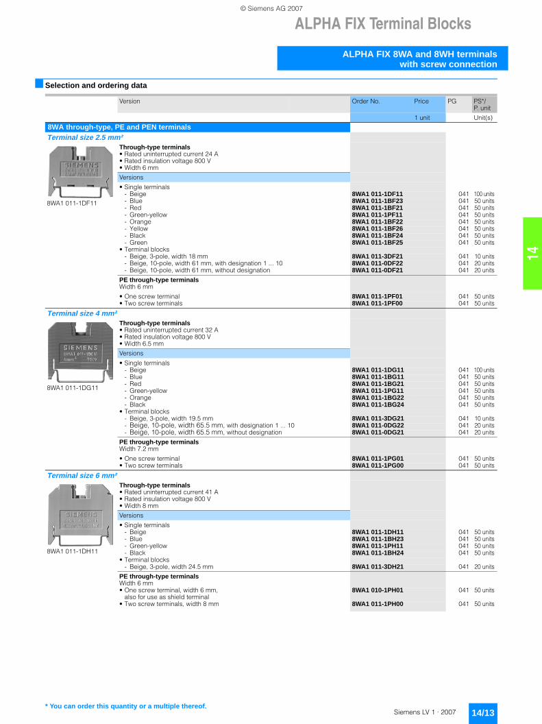
8WA through-type, PE and PEN terminalsTerminal size 2.5 mm²
8WA1 011-1DF11
Through-type terminals• Rated uninterrupted current 24 A• Rated insulation voltage 800 V• Width 6 mm
Versions
• Single terminals- Beige 8WA1 011-1DF11 041 100 units- Blue 8WA1 011-1BF23 041 50 units- Red 8WA1 011-1BF21 041 50 units- Green-yellow 8WA1 011-1PF11 041 50 units- Orange 8WA1 011-1BF22 041 50 units- Yellow 8WA1 011-1BF26 041 50 units- Black 8WA1 011-1BF24 041 50 units- Green 8WA1 011-1BF25 041 50 units
• Terminal blocks- Beige, 3-pole, width 18 mm 8WA1 011-3DF21 041 10 units- Beige, 10-pole, width 61 mm, with designation 1 ... 10 8WA1 011-0DF22 041 20 units- Beige, 10-pole, width 61 mm, without designation 8WA1 011-0DF21 041 20 units
PE through-type terminalsWidth 6 mm
• One screw terminal 8WA1 011-1PF01 041 50 units• Two screw terminals 8WA1 011-1PF00 041 50 units
Terminal size 4 mm²
8WA1 011-1DG11
Through-type terminals• Rated uninterrupted current 32 A• Rated insulation voltage 800 V• Width 6.5 mm
Versions
• Single terminals- Beige 8WA1 011-1DG11 041 100 units- Blue 8WA1 011-1BG11 041 50 units- Red 8WA1 011-1BG21 041 50 units- Green-yellow 8WA1 011-1PG11 041 50 units- Orange 8WA1 011-1BG22 041 50 units- Black 8WA1 011-1BG24 041 50 units
• Terminal blocks- Beige, 3-pole, width 19.5 mm 8WA1 011-3DG21 041 10 units- Beige, 10-pole, width 65.5 mm, with designation 1 ... 10 8WA1 011-0DG22 041 20 units- Beige, 10-pole, width 65.5 mm, without designation 8WA1 011-0DG21 041 20 units
PE through-type terminalsWidth 7.2 mm
• One screw terminal 8WA1 011-1PG01 041 50 units• Two screw terminals 8WA1 011-1PG00 041 50 units
Terminal size 6 mm²
8WA1 011-1DH11
Through-type terminals• Rated uninterrupted current 41 A• Rated insulation voltage 800 V• Width 8 mm
Versions
• Single terminals- Beige 8WA1 011-1DH11 041 50 units- Blue 8WA1 011-1BH23 041 50 units- Green-yellow 8WA1 011-1PH11 041 50 units- Black 8WA1 011-1BH24 041 50 units
• Terminal blocks- Beige, 3-pole, width 24.5 mm 8WA1 011-3DH21 041 20 units
PE through-type terminalsWidth 6 mm• One screw terminal, width 6 mm,
also for use as shield terminal8WA1 010-1PH01 041 50 units
• Two screw terminals, width 8 mm 8WA1 011-1PH00 041 50 units
* You can order this quantity or a multiple thereof.
LV1_14.book Seite 13 Freitag, 26. Januar 2007 11:23 11
© Siemens AG 2007

ALPHA FIX Terminal Blocks
ALPHA FIX 8WA and 8WH terminals with screw connection
14/14 Siemens LV 1 · 2007
14
Terminal size 16 mm²
8WA1 204
Through-type terminals• Rated uninterrupted current 76 A• Rated insulation voltage 800 V• Width 10 mm
Versions
• Single terminals- Beige 8WA1 204 041 20 units- Blue 8WA1 011-1BK11 041 10 units
• Terminal blocks- 3-pole, width 30 mm 8WA1 304 041 20 units
PE through-type terminals and PEN terminals
Width 12 mm
8WA1 011-1PK00 041 25 units
Terminal size 35 mm²
8WA1 205
Through-type terminals• Rated uninterrupted current 125 A• Rated insulation voltage 800 V• Width 16 mm
Versions
• Single terminals- Beige 8WA1 205 041 20 units- Blue 8WA1 011-1BM11 041 10 units
• Terminal blocks- 3-pole, width 48 mm 8WA1 305 041 20 units
PE through-type terminals and PEN terminals• For I = 125 A• Width 16 mm
8WA1 011-1PM00 041 25 units
Terminal size 70 mm²
8WA1 206
Through-type terminals• Rated uninterrupted current 192 A• Rated insulation voltage 800 V• Width 25 mm
Versions
• Beige 8WA1 206 041 10 units• Blue 8WA1 011-1BP11 041 10 units
AccessoriesThermoplast end retainersWidth 10 mm
8WA1 808 041 50 units
Insulation plates• For terminal size 2.5 to 6 mm² 8WA1 825 041 50 units• For terminal size 16 and 35 mm² 8WA1 822-7TK00 041 50 units
Link rails• For terminal size 2.5 mm²
- for two terminals 8WA1 895 041 50 units- for three terminals 8WA1 896 041 50 units- for four terminals 8WA1 897 041 20 units- for ten terminals 8WA1 898 041 10 units
• For terminal size 4 mm²- for two terminals 8WA1 850 041 50 units- for three terminals 8WA1 851 041 50 units- for four terminals 8WA1 852 041 20 units- for ten terminals 8WA1 853 041 10 units
• For terminal size 6 mm²- for two terminals 8WA1 885 041 50 units- for three terminals 8WA1 886 041 50 units- for four terminals 8WA1 887 041 20 units- for ten terminals 8WA1 888 041 10 units
• For terminal size 16 mm²- for two terminals 8WA1 842 041 20 units- for three terminals 8WA1 845 041 20 units- for four terminals 8WA1 848 041 10 units- for ten terminals 8WA1 802 041 10 units
• For terminal size 35 mm²- for two terminals 8WA1 828 041 20 units- for three terminals 8WA1 803 041 20 units- for ten terminals 8WA1 804 041 10 units
• For terminal size 70 mm²- for two terminals 8WA1 216 041 20 units
Barriers• For terminal size 1 to 4 mm² 8WA1 820 041 50 units• For terminal size 6 and 16 mm² 8WA1 821 041 50 units• For terminal size 35 mm² 8WA1 823 041 25 units• For terminal size 70 mm² 8WA1 824 041 25 units
Version Order No. Price PG PS*/P. unit
1 unit Unit(s)
* You can order this quantity or a multiple thereof.
LV1_14.book Seite 14 Freitag, 26. Januar 2007 11:23 11
© Siemens AG 2007

14
ALPHA FIX Terminal Blocks
ALPHA FIX 8WA and 8WH terminalswith screw connection
14/15Siemens LV 1 · 2007
8WA neutral isolating terminals, blue, for neutral busbars 6 x 6 mm
8WA1 011-1NF01
Neutral isolating terminal, terminal size 2.5 mm² 8WA1 011-1NF01 041 50 unitsNeutral isolating terminal, terminal size 4 mm² 8WA1 011-1NG31 041 50 unitsNeutral isolating terminal, terminal size 6 mm² 8WA1 011-1NH01 041 50 unitsNeutral isolating terminal, terminal size 16 mm² 8WA1 604 041 50 units
Accessories
Bars, flat copper• Bare• Rated uninterrupted current 125 A• Approx. 2000 mm long• 6 x 6 mm
8WC5 020 103 1 unit
8WA Insta or three-tier terminalsTerminal size 2.5 mm²
8WA1 011-3JF16
Insta terminals• Rated uninterrupted current 24 A• Rated insulation voltage
- 400 V between phase conductors- 250 V between phase and protective conductors and for neutral isolating
distance• Width 6 mm
Versions
• PE, L, L 8WA1 011-3JF16 041 50 units• PE, L, N 8WA1 011-3JF17 041 50 units• L, L 8WA1 011-3JF18 041 50 units• PE, L, NT 8WA1 011-3JF20 041 50 units
Accessories
Insulation plates, for terminal size 2.5 ... 6 mm² 8WA1 825 041 50 units
Feed-in terminals, for neutral busbars• Connection up to 4 mm² 8WA2 867 041 50 units• Connection up to 25 mm² 8WA2 868 041 50 units• Connection up to 35 mm² 8WA2 870 041 50 units
End retainers, thermoplast 8WA1 808 041 50 units
N/NP bars 8GF9 324-2 042 10 units
Bars, flat copper 8WC5 020 103 1 unit
Link rails, for Insta terminals• For two terminals 8WA1 822-7VF02 041 50 units• For three terminals 8WA1 822-7VF03 041 50 units• For four terminals 8WA1 822-7VF04 041 20 units• For ten terminals 8WA1 822-7VF10 041 10 units
Barriers, for Insta terminals 8WA1 822-7TH00 041 50 units
8WA two-tier terminalsTerminal size 4 mm²
8WA1 011-6DG11
Two-tier terminals• Rated uninterrupted current 32 A• Rated insulation voltage 690 V (with end plate 800 V)• Width 6.5 mm
Versions
• Beige- 1-pole 8WA1 011-6DG11 041 50 units- 2-pole, with 2 electrically isolated links 8WA1 011-2DG11 041 50 units
Accessories
Bridges• For top level with 2-pole terminals 8WA1 822-7VG00 041 50 units• For bottom level with 1-pole and 2-pole terminals 8WA1 822-7VG01 041 50 units
Link rails• For top level with 2-pole terminals
- for two terminals 8WA1 850 041 50 units- for three terminals 8WA1 851 041 50 units- for four terminals 8WA1 852 041 20 units- for ten terminals 8WA1 853 041 10 units
• For bottom level with 1-pole and 2-pole terminals- for two terminals 8WA1 835 041 50 units- for ten terminals 8WA1 838 041 10 units
Barriers 8WA1 823 041 25 units
Version Order No. Price PG PS*/P. unit
1 unit Unit(s)
* You can order this quantity or a multiple thereof.
LV1_14.book Seite 15 Freitag, 26. Januar 2007 11:23 11
© Siemens AG 2007

ALPHA FIX Terminal Blocks
ALPHA FIX 8WA and 8WH terminals with screw connection
14/16 Siemens LV 1 · 2007
14
8WA two-tier terminals with solid-state componentsTerminal size 4 mm²
8WA1 011-6EG20
Diode terminals• Rated insulation voltage 250 V• Width 6.5 mm
Versions
• Rated uninterrupted current 32/1 A 8WA1 011-6EG20 041 10 units
• Rated uninterrupted current 32/1 A 8WA1 011-6EG21 041 10 units
• Rated uninterrupted current 1 A 8WA1 011-6EG22 041 10 units
• Rated uninterrupted current 32/1 A 8WA1 011-6EG23 041 10 units
• Rated uninterrupted current 32/1 A 8WA1 011-6EG24 041 10 units
8WA terminals for componentsTerminal size 1.5 mm²
8WA1 011-1EE00
Terminals for components (only enclosures)• Rated uninterrupted current 6.3 A• Rated insulation voltage 500 V• Width 10 mm
8WA1 011-1EE00 041 5 units
8WA1 822-7EE00
Plugs for components• Rated uninterrupted current 6.3 A• Rated insulation voltage 500 V• Width 10 mm
8WA1 822-7EE00 041 1 unit
8WA fuse terminalsTerminal size 1.5 mm²
8WA1 011-1SF12
Fuse terminals• Rated uninterrupted current 6.3 A when using fuses• Rated uninterrupted current 16 A when using the bridging link• Rated insulation voltage 250 V when using fuses• Rated insulation voltage 800 V when using the bridging link• Width 10 mm
Versions
• For G fuse- without LED 8WA1 011-1SF12 041 10 units- with LED, 24 V AC/DC 8WA1 011-1SF13 041 10 units- with LED, 48 V AC/DC 8WA1 011-1SF14 041 10 units- with LED, 230 V AC/DC 8WA1 011-1SF15 041 10 units
• For inch fuse- without LED 8WA1 011-1SF30 041 10 units- with LED, 24 V AC/DC 8WA1 011-1SF31 041 10 units- with LED, 120 V AC / 110 V DC 8WA1 011-1SF32 041 10 units
Version Order No. Price PG PS*/P. unit
1 unit Unit(s)
* You can order this quantity or a multiple thereof.
LV1_14.book Seite 16 Freitag, 26. Januar 2007 11:23 11
© Siemens AG 2007
14
ALPHA FIX Terminal Blocks
ALPHA FIX 8WA and 8WH terminalswith spring-loaded connection
14/17Siemens LV 1 · 2007
■ Selection and ordering data
Version Order No. Price PG PS*/P. unit
1 unit Unit(s)
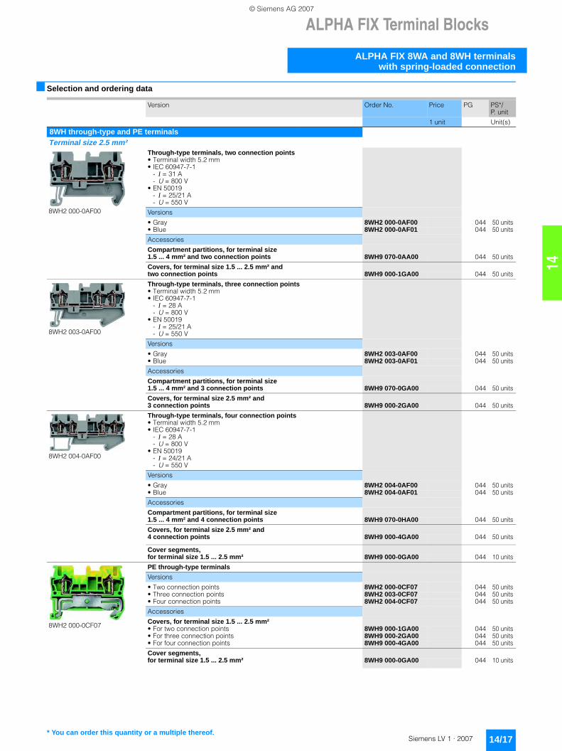
8WH through-type and PE terminalsTerminal size 2.5 mm²
8WH2 000-0AF00
Through-type terminals, two connection points• Terminal width 5.2 mm• IEC 60947-7-1
- I = 31 A- U = 800 V
• EN 50019- I = 25/21 A- U = 550 V
Versions
• Gray 8WH2 000-0AF00 044 50 units• Blue 8WH2 000-0AF01 044 50 units
Accessories
Compartment partitions, for terminal size 1.5 ... 4 mm² and two connection points 8WH9 070-0AA00 044 50 units
Covers, for terminal size 1.5 ... 2.5 mm² and two connection points 8WH9 000-1GA00 044 50 units
8WH2 003-0AF00
Through-type terminals, three connection points• Terminal width 5.2 mm• IEC 60947-7-1
- I = 28 A- U = 800 V
• EN 50019- I = 25/21 A- U = 550 V
Versions
• Gray 8WH2 003-0AF00 044 50 units• Blue 8WH2 003-0AF01 044 50 units
Accessories
Compartment partitions, for terminal size 1.5 ... 4 mm² and 3 connection points 8WH9 070-0GA00 044 50 units
Covers, for terminal size 2.5 mm² and 3 connection points 8WH9 000-2GA00 044 50 units
8WH2 004-0AF00
Through-type terminals, four connection points• Terminal width 5.2 mm• IEC 60947-7-1
- I = 28 A- U = 800 V
• EN 50019- I = 24/21 A- U = 550 V
Versions
• Gray 8WH2 004-0AF00 044 50 units• Blue 8WH2 004-0AF01 044 50 units
Accessories
Compartment partitions, for terminal size 1.5 ... 4 mm² and 4 connection points 8WH9 070-0HA00 044 50 units
Covers, for terminal size 2.5 mm² and 4 connection points 8WH9 000-4GA00 044 50 units
Cover segments, for terminal size 1.5 ... 2.5 mm² 8WH9 000-0GA00 044 10 units
8WH2 000-0CF07
PE through-type terminals
Versions
• Two connection points 8WH2 000-0CF07 044 50 units• Three connection points 8WH2 003-0CF07 044 50 units• Four connection points 8WH2 004-0CF07 044 50 units
Accessories
Covers, for terminal size 1.5 ... 2.5 mm²• For two connection points 8WH9 000-1GA00 044 50 units• For three connection points 8WH9 000-2GA00 044 50 units• For four connection points 8WH9 000-4GA00 044 50 units
Cover segments, for terminal size 1.5 ... 2.5 mm² 8WH9 000-0GA00 044 10 units
* You can order this quantity or a multiple thereof.
LV1_14.book Seite 17 Freitag, 26. Januar 2007 11:23 11
© Siemens AG 2007

ALPHA FIX Terminal Blocks
ALPHA FIX 8WA and 8WH terminals with spring-loaded connection
14/18 Siemens LV 1 · 2007
14
Terminal size 4 mm²
8WH2 000-0AG00
Through-type terminals, two connection points• Terminal width 6.2 mm• IEC 60947-7-1
- I = 40 A- U = 800 V
• EN 50019- I = 34/30 A- U = 550 V
Versions
• Gray 8WH2 000-0AG00 044 50 units• Blue 8WH2 000-0AG01 044 50 units
Accessories
Compartment partitions, for terminal size 1.5 ... 4 mm² and two connection points 8WH9 070-0AA00 044 50 units
Covers, for terminal size 4 mm² and two connection points 8WH9 003-1GA00 044 50 units
8WH2 003-0AG00
Through-type terminals, three connection points• Terminal width 6.2 mm• IEC 60947-7-1
- I = 40 A- U = 800 V
• EN 50019- I = 34/29 A- U = 550 V
Versions
• Gray 8WH2 003-0AG00 044 50 units• Blue 8WH2 003-0AG01 044 50 units
Accessories
Compartment partitions, for terminal size 1.5 ... 4 mm² and 3 connection points 8WH9 070-0GA00 044 50 units
Covers, for terminal size 4 mm² and 3 connection points 8WH9 003-2GA00 044 50 units
Cover segments, for terminal size 4 mm²8WH9 003-0GA00 044 10 units
8WH2 004-0AG00
Through-type terminals, four connection points• Terminal width 6.2 mm• IEC 60947-7-1
- I = 40 A- U = 800 V
• EN 50019- I = 34/25 A- U = 550 V
Versions
• Gray 8WH2 004-0AG00 044 50 units• Blue 8WH2 004-0AG01 044 50 units
Accessories
Compartment partitions, for terminal size 1.5 ... 4 mm² and 4 connection points 8WH9 070-0HA00 044 50 units
Covers, for terminal size 4 mm² and 4 connection points 8WH9 003-4GA00 044 50 units
Cover segments, for terminal size 4 mm²8WH9 003-0GA00 044 10 units
8WH2 000-0CG07
PE through-type terminals, terminal size 6.2 mm
Versions
• Two connection points 8WH2 000-0CG07 044 50 units• Three connection points 8WH2 003-0CG07 044 50 units• Four connection points 8WH2 004-0CG07 044 50 units
Accessories
Covers, for terminal size 4 mm²• For two connection points 8WH9 003-1GA00 044 50 units• For three connection points 8WH9 003-2GA00 044 50 units• For four connection points 8WH9 003-4GA00 044 50 units
Cover segments, for terminal size 4 mm²8WH9 003-0GA00 044 10 units
Version Order No. Price PG PS*/P. unit
1 unit Unit(s)
* You can order this quantity or a multiple thereof.
LV1_14.book Seite 18 Freitag, 26. Januar 2007 11:23 11
© Siemens AG 2007

14
ALPHA FIX Terminal Blocks
ALPHA FIX 8WA and 8WH terminalswith spring-loaded connection
14/19Siemens LV 1 · 2007
Terminal size 6 mm²
8WH2 000-0AH00
Through-type terminals, two connection points• Terminal width 8.2 mm• IEC 60947-7-1
- I = 52 A- U = 800 V
• EN 50019- I = 45/36 A- U = 550 V
Versions
• Gray 8WH2 000-0AH00 044 50 units• Blue 8WH2 000-0AH01 044 50 units
Accessories
Compartment partitions, for terminal size 6 mm²8WH9 070-0DA00 044 50 units
Covers, for terminal size 6 mm²8WH9 004-1GA00 044 50 units
Reducing bridges, for terminal size 6 mm², on spring-loaded terminals 2.5 and 4 mm²
8WH9 020-0FC10 044 10 units
8WH2 000-0CH07
PE through-type terminals, two connection points• Terminal width 8.2 mm
8WH2 000-0CH07 044 50 units
Accessories
Covers, for terminal size 6 mm²8WH9 004-1GA00 044 50 units
8WH2 003-0AH00
Through-type terminals, three connection points• Terminal width 8.2 mm• IEC 60947-7-1
- I = 52 A- U = 800 V
• EN 50019- I = 46/36 A- U = 550 V
Versions
• Gray 8WH2 003-0AH00 044 50 units• Blue 8WH2 003-0AH01 044 50 units
Accessories
Covers, for terminal size 6 mm² and 3 connection points 8WH9 004-2GA00 044 50 units
Reducing bridges, for terminal size 6 mm²,on spring-loaded terminals 2.5 and 4 mm²
8WH9 020-0FC10 044 10 units
8WH2 003-0CH07
PE through-type terminals, three connection points• Terminal width 8.2 mm
8WH2 003-0CH07 044 50 units
Accessories
Covers, for terminal size 6 mm² and 3 connection points 8WH9 004-2GA00 044 50 units
Terminal size 10 mm²
8WH2 000-0AJ00
Through-type terminals• Terminal width 10.2 mm• IEC 60947-7-1
- I = 65 A- U = 800 V
• EN 50019- I = 50/63 A- U = 550 V
Versions
• Gray 8WH2 000-0AJ00 044 50 units• Blue 8WH2 000-0AJ01 044 50 units
Accessories
Covers, for terminal size 10 mm²8WH9 005-1GA00 044 50 units
Reducing bridges, for terminal size 10 mm², on spring-loaded terminals 2.5 and 4 mm²
8WH9 020-0AC10 044 10 units
8WH2 000-0CJ07
PE through-type terminals• Terminal width 10.2 mm
- I = 65 A
8WH2 000-0CJ07 044 50 units
Accessories
Covers, for terminal size 10 mm²8WH9 005-1GA00 044 50 units
Plug-in bridges, for terminal width 10.2 mm 8WH9 020-6EC10 044 10 units
Version Order No. Price PG PS*/P. unit
1 unit Unit(s)
* You can order this quantity or a multiple thereof.
LV1_14.book Seite 19 Freitag, 26. Januar 2007 11:23 11
© Siemens AG 2007

ALPHA FIX Terminal Blocks
ALPHA FIX 8WA and 8WH terminals with spring-loaded connection
14/20 Siemens LV 1 · 2007
14
Terminal size 16 mm²
8WH2 000-0AK00
Through-type terminals• Terminal width 12 mm• IEC 60947-7-1
- I = 90 A- U = 800 V
• EN 50019- I = 65/82 A- U = 550 V
Versions
• Gray 8WH2 000-0AK00 044 50 units• Blue 8WH2 000-0AK01 044 50 units
Accessories
Covers, for terminal size 16 mm²8WH9 006-1GA00 044 50 units
Reducing bridges, for terminal size 16 mm², on spring-loaded terminals 2.5 and 4 mm²
8WH9 020-0BC10 044 10 units
Plug-in bridges, for terminal width 12 mm 8WH9 020-6FC10 044 10 units
8WH2 000-0CK07
PE through-type terminals• Terminal width 12 mm
- I = 90 A
8WH2 000-0CK07 044 25 units
Accessories
Covers, for terminal size 16 mm²8WH9 006-1GA00 044 50 units
Plug-in bridges, for terminal width 12 mm 8WH9 020-6FC10 044 10 units
Terminal size 35 mm²
8WH2 000-0AM00
Through-type terminals, terminal size 35 mm²• Insulated on both sides• Terminal width 16 mm• IEC 60947-7-1
- I = 125 A- U = 800 V
• EN 50019- I = 108 A- U = 750 V
Versions
• Gray 8WH2 000-0AM00 044 10 units• Blue 8WH2 000-0AM01 044 10 units
Accessories
Reducing bridges, for terminal size 35 mm²• For linking terminal sizes 2.5 and 4 mm² 8WH9 020-0EC10 044 10 units• For linking terminal sizes 16 mm² 8WH9 020-0DC10 044 10 units
Plug-in bridges, for terminal width 16 mm 8WH9 020-6GC10 044 10 units
8WH2 000-0CM07
PE through-type terminals, terminal size 35 mm²• Insulated on both sides• Terminal width 16 mm
- I = 125 A
8WH2 000-0CM07 044 10 units
Accessories
Plug-in bridges, for terminal width 16 mm 8WH9 020-6GC10 044 10 units
8WH fuse terminalsTerminal size 4 mm²
8WH2 000-1GG08
Fuse terminals, for G fuse links 5 x 20 mm• Terminal width 6.2 mm• With fuse
- Imax = 6.3 A, short-circuit protection only, stand-alone 4 W, group 2.5 W
- U = 250 V, overload protection, stand-alone 4 W, group 1.6 W• As isolating terminals
- I = 6.3 A- U = 250 V
Versions
• Without illuminated indicator 8WH2 000-1GG08 044 50 units• Illuminated indicator 15 ... 30 V 8WH2 000-1JG38 044 50 units• Illuminated indicator 30 ... 60 V 8WH2 000-1JG68 044 50 units• Illuminated indicator 110 ... 250 V 8WH2 000-1MG08 044 50 units
Accessories
Compartment partitions, for terminal sizes 1.5 and 4 mm² and two connection points
8WH9 070-0AA00 044 50 units
Version Order No. Price PG PS*/P. unit
1 unit Unit(s)
* You can order this quantity or a multiple thereof.
LV1_14.book Seite 20 Freitag, 26. Januar 2007 11:23 11
© Siemens AG 2007

14
ALPHA FIX Terminal Blocks
ALPHA FIX 8WA and 8WH terminalswith spring-loaded connection
14/21Siemens LV 1 · 2007
8WH isolating terminalsTerminal size 2.5 mm²
8WH2 000-6AF00
Isolating terminals• Gray• Terminal width 5.2 mm
- Current and voltage are determined by the plug used- I = 16 A- U = 400 V
Versions
• Two connection points 8WH2 000-6AF00 044 50 units• Three connection points 8WH2 003-6AF00 044 50 units• Four connection points 8WH2 004-6AF00 044 50 units
AccessoriesIsolating plugsOrange
8WH9 040-0DB04 044 50 units
8WH9 040-3DB08
Fused plugs, without illuminated indicator• Black• Imax: 6.3 A
8WH9 040-3DB08 044 10 units
8WH9 040-0BB00
Component plugs 8WH9 040-0BB00 044 10 units
Compartment partitions, for terminal size 2.5 mm²• For three connection points 8WH9 070-0GA00 044 50 units• For four connection points 8WH9 070-0HA00 044 50 units
Cover segments, for terminal size 1.5 and 2.5 mm² and three or four connection points 8WH9 000-0GA00 044 10 units
8WH two-tier terminalsTerminal size 2.5 mm²
8WH2 020-0AF00
Two-tier terminals• Terminal width 5.2 mm• IEC 60947-7-1
- I = 26 A- U= 500 V
• EN 50019- I = 23/19 A- U = 420 V
Versions
• Gray- without potential link, 2-pole 8WH2 020-0AF00 044 50 units- with potential link, 1-pole 8WH2 025-0AF00 044 50 units
• Blue- without potential link, 2-pole 8WH2 020-0AF01 044 50 units- with potential link, 1-pole 8WH2 025-0AF01 044 50 units
8WH2 020-0CF07
PE two-tier terminals, two connection points on one level• Terminal width 5.2 mm
8WH2 020-0CF07 044 50 units
AccessoriesCovers, for terminal size 1.5 ... 2.5 mm²
8WH9 000-1VA00 044 50 units
Version Order No. Price PG PS*/P. unit
1 unit Unit(s)
* You can order this quantity or a multiple thereof.
LV1_14.book Seite 21 Freitag, 26. Januar 2007 11:23 11
© Siemens AG 2007
ALPHA FIX Terminal Blocks
ALPHA FIX 8WH combination plug-in terminals
14/22 Siemens LV 1 · 2007
14
■ Selection and ordering data
Version Order No. Price PG PS*/P. unit
1 unit Unit(s)
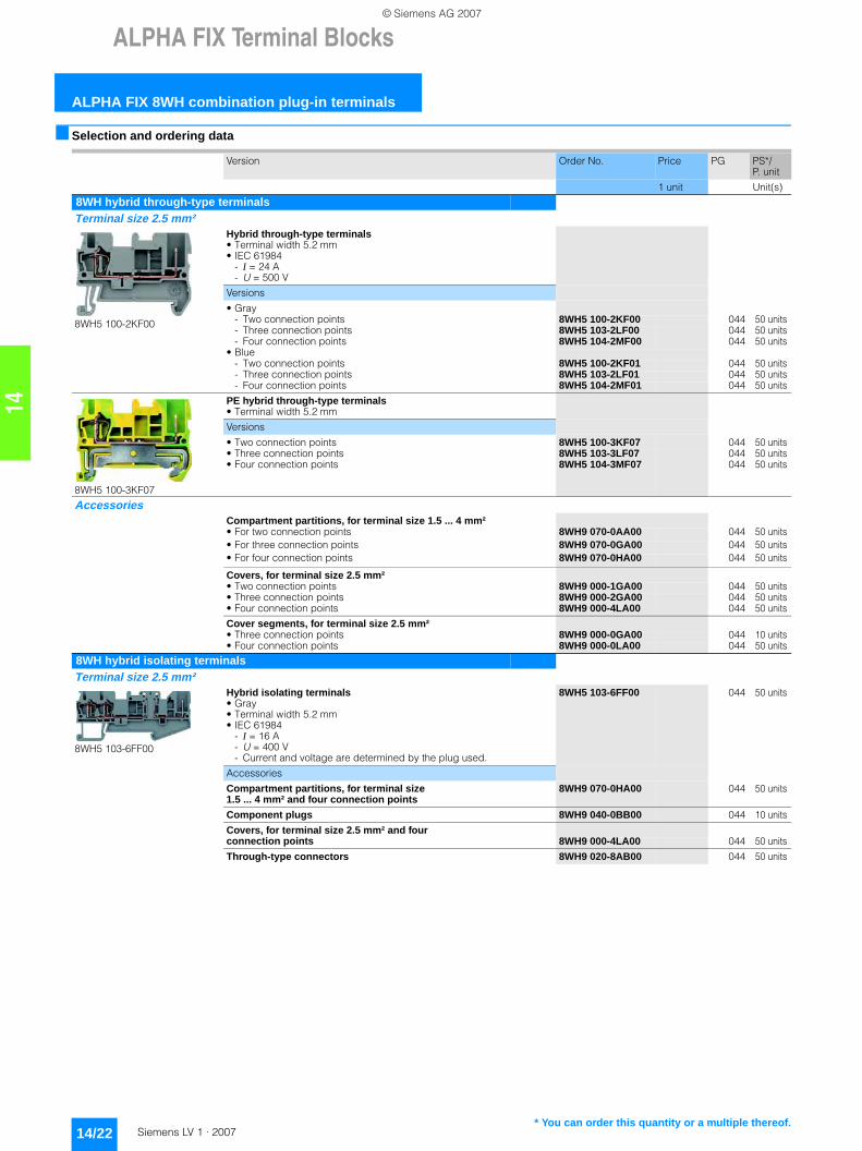
8WH hybrid through-type terminalsTerminal size 2.5 mm²
8WH5 100-2KF00
Hybrid through-type terminals• Terminal width 5.2 mm• IEC 61984
- I = 24 A- U = 500 V
Versions
• Gray- Two connection points 8WH5 100-2KF00 044 50 units- Three connection points 8WH5 103-2LF00 044 50 units- Four connection points 8WH5 104-2MF00 044 50 units
• Blue- Two connection points 8WH5 100-2KF01 044 50 units- Three connection points 8WH5 103-2LF01 044 50 units- Four connection points 8WH5 104-2MF01 044 50 units
8WH5 100-3KF07
PE hybrid through-type terminals• Terminal width 5.2 mm
Versions
• Two connection points 8WH5 100-3KF07 044 50 units• Three connection points 8WH5 103-3LF07 044 50 units• Four connection points 8WH5 104-3MF07 044 50 units
AccessoriesCompartment partitions, for terminal size 1.5 ... 4 mm²• For two connection points 8WH9 070-0AA00 044 50 units• For three connection points 8WH9 070-0GA00 044 50 units• For four connection points 8WH9 070-0HA00 044 50 units
Covers, for terminal size 2.5 mm²• Two connection points 8WH9 000-1GA00 044 50 units• Three connection points 8WH9 000-2GA00 044 50 units• Four connection points 8WH9 000-4LA00 044 50 units
Cover segments, for terminal size 2.5 mm²• Three connection points 8WH9 000-0GA00 044 10 units• Four connection points 8WH9 000-0LA00 044 50 units
8WH hybrid isolating terminalsTerminal size 2.5 mm²
8WH5 103-6FF00
Hybrid isolating terminals• Gray• Terminal width 5.2 mm• IEC 61984
- I = 16 A- U = 400 V- Current and voltage are determined by the plug used.
8WH5 103-6FF00 044 50 units
Accessories
Compartment partitions, for terminal size 1.5 ... 4 mm² and four connection points
8WH9 070-0HA00 044 50 units
Component plugs 8WH9 040-0BB00 044 10 units
Covers, for terminal size 2.5 mm² and four connection points 8WH9 000-4LA00 044 50 units
Through-type connectors 8WH9 020-8AB00 044 50 units
* You can order this quantity or a multiple thereof.
LV1_14.book Seite 22 Freitag, 26. Januar 2007 11:23 11
© Siemens AG 2007

14
ALPHA FIX Terminal Blocks
ALPHA FIX 8WH combination plug-in terminals
14/23Siemens LV 1 · 2007
8WH plugsTerminal size 2.5 mm²
8WH9 040-1DB00/-1AB00
PlugsTerminal width 5.2 mm
- I = 24 A- U = 500 V
Versions
• Gray- Left element, can be bridged 8WH9 040-1DB00 044 50 units- Center element, can be bridged 8WH9 040-1EB00 044 50 units- Right element, can be bridged 8WH9 040-1FB00 044 50 units
- Left element, cannot be bridged 8WH9 040-1AB00 044 50 units- Center element, cannot be bridged 8WH9 040-1BB00 044 50 units- Right element, cannot be bridged 8WH9 040-1CB00 044 50 units
• Blue- Left element, can be bridged 8WH9 040-1DB01 044 50 units- Center element, can be bridged 8WH9 040-1EB01 044 50 units- Right element, can be bridged 8WH9 040-1FB01 044 50 units
- Left element, cannot be bridged 8WH9 040-1AB01 044 50 units- Center element, cannot be bridged 8WH9 040-1BB01 044 50 units- Right element, cannot be bridged 8WH9 040-1CB01 044 50 units
8WH9 040-1DB07/-1AB07
PE plugsTerminal width 5.2 mm
- I = 24 A- U = 500 V
Versions
• Left element, can be bridged 8WH9 040-1DB07 044 50 units• Center element, can be bridged 8WH9 040-1EB07 044 50 units• Right element, can be bridged 8WH9 040-1FB07 044 50 units
• Left element, cannot be bridged 8WH9 040-1AB07 044 50 units• Center element, cannot be bridged 8WH9 040-1BB07 044 50 units• Right element, cannot be bridged 8WH9 040-1CB07 044 50 units
Accessories
8WH9 050-2BA04
Latching• With strain relief 8WH9 050-2BA04 044 50 units• Without strain relief 8WH9 050-2AA04 044 50 units
Version Order No. Price PG PS*/P. unit
1 unit Unit(s)
* You can order this quantity or a multiple thereof.
LV1_14.book Seite 23 Freitag, 26. Januar 2007 11:23 11
© Siemens AG 2007

ALPHA FIX Terminal Blocks
ALPHA FIX 8WH terminalswith plug-in connection
14/24 Siemens LV 1 · 2007
14
■ Selection and ordering data
Version Order No. Price PG PS*/P. unit
1 unit Unit(s)
8WH through-type and PE terminalsTerminal size 2.5 mm²
8WH4 000-0AF00
Through-type terminals• Terminal width 5.2 mm• Maximum load current 30 A• Rated voltage 800 V
Versions
• Gray 8WH4 000-0AF00 044 50 units• Blue 8WH4 000-0AF01 044 50 units
8WH4 000-0CF07
PE through-type terminalsTerminal width 5.2 mm
8WH4 000-0CF07 044 50 units
Terminal size 4 mm²
8WH4 000-0AG00
Through-type terminals• Terminal width 6.2 mm• Maximum load current 41 A• Rated voltage 800 V
Versions
• Gray 8WH4 000-0AG00 044 50 units• Blue 8WH4 000-0AG01 044 50 units
8WH4 000-0CG07
PE through-type terminals• Terminal width 6.2 mm• Cross-section max. 6 mm²
8WH4 000-0CG07 044 50 units
Terminal size 6 mm²
8WH4 000-0AH00
Through-type terminals• Terminal width 8.2 mm• Maximum load current 51 A• Rated voltage 800 V
Versions
• Gray 8WH4 000-0AH00 044 50 units• Blue 8WH4 000-0AH01 044 50 units
8WH4 000-0CH07
PE through-type terminalsTerminal width 8.2 mm
8WH4 000-0CH07 044 50 units
AccessoriesCovers
• For terminal size 2.5 mm² 8WH9 000-1WA00 044 50 units• For terminal size 4 mm² 8WH9 003-7WA00 044 50 units• For terminal size 6 mm² 8WH9 004-1WA00 044 50 units
* You can order this quantity or a multiple thereof.
LV1_14.book Seite 24 Freitag, 26. Januar 2007 11:23 11
© Siemens AG 2007

14
ALPHA FIX Terminal Blocks
ALPHA FIX 8WH terminalswith plug-in connection
14/25Siemens LV 1 · 2007
8WH neutral isolating terminals, for neutral busbars 3 x 10 mm Terminal size 2.5 mm²
8WH4 000-0BF00
Neutral isolating terminals• Terminal width 5.2 mm• Maximum load current 30 A• Rated voltage 400 V
Versions
• Two connection points 8WH4 000-0BF00 044 50 units• Three connection points 8WH4 003-0BF00 044 50 units
Terminal size 4 mm²
8WH4 000-0BG00
Neutral isolating terminals• Terminal width 6.2 mm• Maximum load current 36 A• Rated voltage 400 V
Versions
• Two connection points 8WH4 000-0BG00 044 50 units• Three connection points 8WH4 003-0BG00 044 50 units
Terminal size 6 mm²
8WH4 000-0BH00
Neutral isolating terminals, two connection points• Terminal width 8.2 mm• Maximum load current 51 A• Rated voltage 400 V
8WH4 000-0BH00 044 50 units
Accessories
8WH9 140-0AF01
Supports
• For terminal size 2.5 ... 4 mm² 8WH9 140-0AF01 044 50 units• For terminal size 6 mm² 8WH9 141-0AH01 044 50 units
Covers
• For terminal size 2.5 mm² 8WH9 000-1WA00 044 50 units• For terminal size 4 mm² 8WH9 003-7WA00 044 50 units• For terminal size 6 mm² 8WH9 004-1WA00 044 50 units
8WH installation terminals Terminal size 2.5 mm²
8WH4 001-4DF00
Installation terminals, standard version,for neutral busbars 3 x 10 mm • Terminal width 5.2 mm• IEC 60947-7-1 (for variants L - L/L - L/N)
- I = 24 A- U = 400 V, phase conductor/phase conductor
• DIN VDE 0611 (for variants PE/L/L - PE/L/N)- I = 24 A- U = 400 V, phase conductor/phase conductor- U = 250 V, phase conductor/PE
• DIN VDE 0611 (for variants PE/L/NT)- I = 20 A- U = 400 V, phase conductor/phase conductor- U = 250 V, phase conductor/PE- U = 250 V, phase conductor/N
Versions
• L 8WH4 001-0AF00 044 50 units• L/L 8WH4 001-4DF00 044 50 units• L/N 8WH4 001-4CF00 044 50 units• PE/L/L 8WH4 001-4HF00 044 50 units• PE/L/N 8WH4 001-4EF00 044 50 units• PE/L/NT 8WH4 001-4FF00 044 50 units
Accessories
Supports, for terminal size 2.5 mm² 8WH9 141-0AF01 044 50 units
Covers, for terminal size 2.5 mm²8WH9 000-3WA00 044 50 units
Version Order No. Price PG PS*/P. unit
1 unit Unit(s)
* You can order this quantity or a multiple thereof.
LV1_14.book Seite 25 Freitag, 26. Januar 2007 11:23 11
© Siemens AG 2007

ALPHA FIX Terminal Blocks
ALPHA FIX 8WH with insulation displacement terminals
14/26 Siemens LV 1 · 2007
14
■ Selection and ordering data
Version Order No. Price PG PS*/P. unit
Unit(s)
Through-type and PE terminalsTerminal size 1.5 mm²
8WH3 000-0AE00
Through-type terminals• Terminal width 5.2 mm
- I = 17.5 A- U = 800 V
• EN 50019- I = 16 A- U = 550 V
Versions
• Gray- two connection points 8WH3 000-0AE00 044 50 units- three connection points 8WH3 003-0AE00 044 50 units- four connection points 8WH3 004-0AE00 044 50 units
• Blue- two connection points 8WH3 000-0AE01 044 50 units- three connection points 8WH3 003-0AE01 044 50 units- four connection points 8WH3 004-0AE01 044 50 units
8WH3 000-0CE07
PE through-type terminals• Terminal width 5.2 mm
Versions
• Two connection points 8WH3 000-0CE07 044 50 units• Three connection points 8WH3 003-0CE07 044 50 units• Four connection points 8WH3 004-0CE07 044 50 units
Accessories
Cover segments, for terminal size 1.5 mm² and three or four connection points 8WH9 001-0AA00 044 50 units
Terminal size 2.5 mm²
8WH3 000-0AF00
Through-type terminals• Terminal width 6.2 mm
- I = 24 A- U = 800 V
Versions
• Gray- two connection points 8WH3 000-0AF00 044 50 units- three connection points 8WH3 003-0AF00 044 50 units
• Blue- two connection points 8WH3 000-0AF01 044 50 units- three connection points 8WH3 003-0AF01 044 50 units
8WH3 000-0CF07
PE through-type terminals• Terminal width 6.2 mm
Versions
• Two connection points 8WH3 000-0CF07 044 50 units• Three connection points 8WH3 003-0CF07 044 50 units
AccessoriesCompartment partitions, for terminal size 1.5 ... 2.5 mm²• Two connection points 8WH9 070-0JA00 044 50 units• Three connection points 8WH9 070-0KA00 044 50 units• Four connection points 8WH9 070-0LA00 044 50 units
Modular test plugs
• For terminal width 5.2 mm 8WH9 010-0EB02 044 10 units• For terminal width 6.2 mm 8WH9 010-0FB02 044 10 units
Covers
• For terminal size 1.5 mm²- two connection points 8WH9 001-1AA00 044 50 units- three connection points 8WH9 001-2AA00 044 50 units- four connection points 8WH9 001-4AA00 044 50 units
• For terminal size 2.5 mm²- two connection points 8WH9 000-1AA00 044 50 units- three connection points 8WH9 000-2AA00 044 50 units
* You can order this quantity or a multiple thereof.
LV1_14.book Seite 26 Freitag, 26. Januar 2007 11:23 11
© Siemens AG 2007

14
ALPHA FIX Terminal Blocks
Accessories for 8WA and 8WH
14/27Siemens LV 1 · 2007
■ Selection and ordering data
Version Order No. Price PG PS*/P. unit
1 unit Unit(s)
8WA labeling accessoriesLabeling plates with inscription
Vertical inscription (8WA8 860–0AA)
Horizontal inscription (8WA8 861–0AA)
Labeling plates, type 8WA8 860/861• Label size 5 mm x 7 mm• Letter height 2 mm • Grid size 6.2 mm
Versions
• Vertical inscription 8WA8 860-@@@ 041 200 units• Horizontal inscription 8WA8 861-@@@ 041 200 units
Inscription
• 1 ... 5 (40 x) 0BA• 6 … 10 (40 x) 0BB• 11 … 15 (40 x) 0BC• 16 … 20 (40 x) 0BD• 21 … 25 (40 x) 0BE
• 26 … 30 (40 x) 0BF• 31 … 35 (40 x) 0BG• 36 … 40 (40 x) 0BH• 41 … 45 (40 x) 0BJ• 46 … 50 (40 x) 0BK
• 51 … 55 (40 x) 0BL• 56 … 60 (40 x) 0BM• 61 … 65 (40 x) 0BN• 66 … 70 (40 x) 0BP• 71 … 75 (40 x) 0BQ
Labeling plates, customized inscription• Label size 5 mm x 7 mm• Letter height 2 mm • Grid size 6.2 mm • Required inscription to be specified in plain text
Versions
• Vertical inscription 8WA8 847-0XA 041 100 units• Horizontal inscription 8WA8 848-0XA 041 100 units
8WH labeling accessories, labeling plates with inscriptionTerminal width 5.2 mm
8WH8 120-2AB05
8WH8 120-2AA15
Labels, front, with vertical inscription• Consecutive numbers
- 1 ... 10 (10 ×) 8WH8 120-2AB05 044 100 units- 11 ... 20 (10 ×) 8WH8 120-2AB15 044 100 units- 21 ... 30 (10 ×) 8WH8 120-2AB25 044 100 units- 31 ... 40 (10 ×) 8WH8 120-2AB35 044 100 units- 41 ... 50 (10 ×) 8WH8 120-2AB45 044 100 units- 51 ... 60 (10 ×) 8WH8 120-2AB55 044 100 units- 61 ... 70 (10 ×) 8WH8 120-2AB65 044 100 units- 71 ... 80 (10 ×) 8WH8 120-2AB75 044 100 units- 81 ... 90 (10 ×) 8WH8 120-2AB85 044 100 units- 91 ... 100 (10 ×) 8WH8 120-2AC05 044 100 units
• L1/L2/L3/N/PE 8WH8 120-2AA15 044 100 units• Special inscriptions 8WH8 120-2XA05 044 100 units
8WH8 110-2AA05
Labels, front, without inscription8WH8 110-2AA05 044 100 units
8WH8 111-2AA05
Labels, flat, without inscription8WH8 111-2AA05 044 100 units
Terminal width 6.2 mm
8WH8 120-3AB05
Labels, front, with vertical inscription• Consecutive numbers
- 1 ... 10 (10 ×) 8WH8 120-3AB05 044 100 units- 11 ... 20 (10 ×) 8WH8 120-3AB15 044 100 units- 21 ... 30 (10 ×) 8WH8 120-3AB25 044 100 units- 31 ... 40 (10 ×) 8WH8 120-3AB35 044 100 units- 41 ... 50 (10 ×) 8WH8 120-3AB45 044 100 units- 51 ... 60 (10 ×) 8WH8 120-3AB55 044 100 units
8WH8 110-3AA05
Labels, front, without inscription8WH8 110-3AA05 044 100 units
8WH8 111-3AA05
Labels, flat, without inscription8WH8 111-3AA05 044 100 units
▲
* You can order this quantity or a multiple thereof.
LV1_14.book Seite 27 Freitag, 26. Januar 2007 11:23 11
© Siemens AG 2007

ALPHA FIX Terminal Blocks
Accessories for 8WA and 8WH
14/28 Siemens LV 1 · 2007
14
Terminal width 8.2 mm
8WH8 120-4AB05
8WH8 120-4AA15
Labels, front, with vertical inscription• Consecutive numbers
- 1 ... 10 (10 ×) 8WH8 120-4AB05 044 100 units- 11 ... 20 (10 ×) 8WH8 120-4AB15 044 100 units- 21 ... 30 (10 ×) 8WH8 120-4AB25 044 100 units- 31 ... 40 (10 ×) 8WH8 120-4AB35 044 100 units- 41 ... 50 (10 ×) 8WH8 120-4AB45 044 100 units
8WH8 110-4AA05
Labels, front, without inscription8WH8 110-4AA05 044 100 units
8WH8 111-4AA05
Labels, flat, without inscription8WH8 111-4AA05 044 100 units
Terminal width 10 mm
8WH8 120-5AB05
8WH8 120-5AA15
8WH8 120-5AA25
Labels, front, with vertical inscription• Consecutive numbers
- 1 ... 10 (10 ×) 8WH8 120-5AB05 044 100 units- 11 ... 20 (10 ×) 8WH8 120-5AB15 044 100 units- 21 ... 30 (10 ×) 8WH8 120-5AB25 044 100 units- 31 ... 40 (10 ×) 8WH8 120-5AB35 044 100 units
• L1/L2/L3/N/PE 8WH8 120-5AA15 044 100 units• Special inscriptions 8WH8 120-5XA05 044 100 units• U/V/W/N/Grounding 8WH8 120-5AA25 044 100 units
8WH8 110-5AA05
Labels, front, without inscription8WH8 110-5AA05 044 100 units
8WH8 111-5AA05Labels, flat, without inscription
8WH8 111-5AA05 044 100 units
Terminal width 15 mmLabels, flat, without inscription
8WH8 111-7AA05 044 100 units
8WH mounting accessories
8WH9 150-0CA00
Quick-assembly end retainers• Can be inscribed with labels, front, for terminal width 5.2 mm and
terminal strip marker
8WH9 150-0CA00 044 50 units
Through-type connectors• Gray• Imax: 16 A
8WH9 020-8AB00 044 50 units
8WH9 020-6AC10
Plug-in bridges• For terminal width 4.2 mm
- 2-pole 8WH9 020-6AC10 044 50 units- 3-pole 8WH9 020-6AD10 044 50 units- 4-pole 8WH9 020-6AE10 044 50 units- 5-pole 8WH9 020-6AF10 044 50 units- 10-pole 8WH9 020-6AL10 044 10 units- 20-pole 8WH9 020-6AS10 044 10 units
• For terminal width 5.2 mm- 2-pole 8WH9 020-6BC10 044 50 units- 3-pole 8WH9 020-6BD10 044 50 units- 4-pole 8WH9 020-6BE10 044 50 units- 5-pole 8WH9 020-6BF10 044 50 units- 10-pole 8WH9 020-6BL10 044 10 units- 20-pole 8WH9 020-6BS10 044 10 units- 50-pole 8WH9 020-6BT10 044 10 units
• For terminal width 6.2 mm- 2-pole 8WH9 020-6CC10 044 50 units- 3-pole 8WH9 020-6CD10 044 50 units- 4-pole 8WH9 020-6CE10 044 50 units- 5-pole 8WH9 020-6CF10 044 50 units- 10-pole 8WH9 020-6CL10 044 10 units- 20-pole 8WH9 020-6CS10 044 10 units- 50-pole 8WH9 020-6CT10 044 10 units
• For terminal width 8.2 mm- 2-pole 8WH9 020-6DC10 044 10 units- 3-pole 8WH9 020-6DD10 044 10 units- 4-pole 8WH9 020-6DE10 044 10 units- 5-pole 8WH9 020-6DF10 044 10 units- 10-pole 8WH9 020-6DL10 044 10 units
• For terminal width 10 mm, 2-pole 8WH9 020-6EC10 044 10 units• For terminal width 12 mm, 2-pole 8WH9 020-6FC10 044 10 units• For terminal width 16 mm, 2-pole 8WH9 020-6GC10 044 10 units
Version Order No. Price PG PS*/P. unit
1 unit Unit(s)
* You can order this quantity or a multiple thereof.
LV1_14.book Seite 28 Freitag, 26. Januar 2007 11:23 11
© Siemens AG 2007

14
ALPHA FIX Terminal Blocks
Accessories for 8WA and 8WH
14/29Siemens LV 1 · 2007
■ More information
Catalog ET A1
ALPHA distribution boards and small distribution boards
8WH9 020-0FC10
Reducing bridges• For linking to a through-type terminal, terminal size 2.5 or 4 mm²
- to a through-type terminal, terminal size 6 mm², Imax: 48 A 8WH9 020-0FC10 044 10 units- to a through-type terminal, terminal size 10 mm², Imax: 55 A 8WH9 020-0AC10 044 10 units- to a through-type terminal, terminal size 16 mm², Imax: 64 A 8WH9 020-0BC10 044 10 units- to a through-type terminal, terminal size 35 mm², Imax: 64 A 8WH9 020-0EC10 044 10 units
• For linking to a through-type terminal, terminal size 16 mm²- to a through-type terminal, terminal size 35 mm², Imax: 90 A 8WH9 020-0DC10 044 10 units
8WH9 040-0BB00
Component plugs• Imax: 6 A, depending on the power loss of the components,
max. 1 W for stand-alone arrangement• Can be inscribed with labels, flat, for terminal width 5.2 mm
8WH9 040-0BB00 044 10 units
8WH9 040-3AB08
8WH9 040-3DB08
Fused plugs• Black• Imax: 6.3 A• Can be inscribed with labels, flat, for terminal width 5.2 mm
Versions
• With illuminated indicator for 12 ... 30 V, 1 ... 2.5 mA 8WH9 040-3AB08 044 10 units• With illuminated indicator for 30 ... 60 V, 0.8 ... 2.0 mA 8WH9 040-3BB08 044 10 units• With illuminated indicator for 110 ... 250 V, 0.5 ... 2.5 mA 8WH9 040-3CB08 044 10 units• Without illuminated indicator 8WH9 040-3DB08 044 10 units
Note
The G fuse holders must be selected according to the maximum power loss (self-heating) of the G fuse links. Depending on the application and method of installation, the heating conditions in closed fuse holders must be tested.
Higher ambient temperatures represent an additional load for the fuse links. Hence in such cases of application it is necessary to allow in addition for adjustment of the rated current.
8WH9 040-0DB04
Isolating plugsOrange
8WH9 040-0DB04 044 50 units
8WH9 200-0AA00
Screwdriversfor actuating the tension spring
Versions
• 0.4 x 2.5 mm 8WH9 200-0AA00 044 10 units• 0.4 x 3.5 mm 8WH9 200-0AB00 044 10 units• 0.8 x 4.0 mm 8WH9 200-0AC00 044 10 units• 1.0 x 5.5 mm 8WH9 200-0AD00 044 10 units
Version Order No. Price PG PS*/P. unit
1 unit Unit(s)
* You can order this quantity or a multiple thereof.
LV1_14.book Seite 29 Freitag, 26. Januar 2007 11:23 11
© Siemens AG 2007
ALPHA 8HP Molded-Plastic Distribution System
General data
14/30 Siemens LV 1 · 2007
14
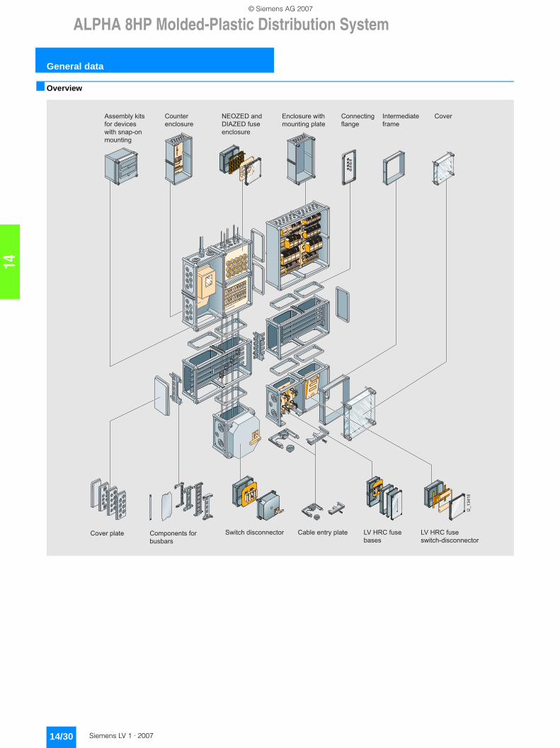
■ Overview
I2_1
3418
Cover plate
NEOZED and DIAZED fuse enclosure
Components for busbars
Assembly kits for devices with snap-on mounting
Intermediate frame
Enclosure with mounting plate
Cable entry plate
Connecting flange
Cover
Switch disconnector LV HRC fuse bases
LV HRC fuse switch-disconnector
Counter enclosure
LV1_14.book Seite 30 Freitag, 26. Januar 2007 11:23 11
© Siemens AG 2007

14
ALPHA 8HP Molded-Plastic Distribution System
General data
14/31Siemens LV 1 · 2007
8HP distribution board with support rack and cable space cover
The 8HP distribution system is a modular system for low-voltage small distribution boards, control panels and power distribution boards.
■ Benefits
The optimum design of these high-quality materials fulfills all the demands made on modern enclosures. This includes:• Total insulation• Corrosion resistance• Mechanical strength• Simple finish• Temperature resistance• Maintenance free• Flame retardant, self-extinguishing
• Halogen-free (thus preventing consequential damage resulting from external fire), excludes cable space cover
• Lightweight components
Total insulation
All enclosure parts and operating mechanisms are constructed so that they fulfill the conditions of the protective measure "total insula-tion" according to DIN VDE 0100, Part 410, when they are closed during operation. Enclosure fixings are situated outside the device installation space.
■ Application
It can be installed in all industrial plants, power stations, in large public or private buildings and in public utilities as well as in office buildings and residential buildings.
The components of the 8HP distribution system fulfill the require-ments specified for type-tested low-voltage controlgear combinati-ons (TTA) according to EN 60439-1/DIN VDE 0660 Part 500. The enclosure corresponds to the protective measure "total insulation" according to DIN VDE 0100.
Standards
DIN VDE 0660 Part 500
Specifications for type-tested low-voltage controlgear combinations (TTA)
DIN VDE 0110
Standards for rating the creepage distances and clearances of electrical equipment
IEC 60439-1
Ready-made controls assemblies for low-voltage
DIN VDE 0660 Part 107
Standards for low-voltage controls
DIN VDE 0100
Standards for the erection of power installations with rated voltages up to 1000 V.
Conformity declaration
This declares conformity of the components and distribution boards with the safety requirements for low-voltage equipment as specified in the EU Directive dated 19.02.1973.
Special tests
Fire tests for equipment used in mining are performed by the Ver-suchsgrube Tremonia, Dortmund, Germany.
Shock tests for equipment used in protective rooms are performed by the "Bundesamt für Zivilschutz", Bad Godesberg, Germany, regulation category RK 1.0/10 to safety level "A", Certificate of Use 036/95.
Earthquake tests are performed by the IAB, Ottobrunn, Germany. Tests for use in EX zone 2 (special version).
The enclosure is UL-certified.
LV1_14.book Seite 31 Freitag, 26. Januar 2007 11:23 11
© Siemens AG 2007

ALPHA 8HP Molded-Plastic Distribution System
General data
14/32 Siemens LV 1 · 2007
14
Installation conditions
Conversion from Pg to metric glands
A new option for using metric screwed glands was tested for the 8HP molded-plastic distribution system. The result of this test showed that the Pg openings listed in the following table are also suitable for the use of metric glands. Metric glands with lock nuts are used. Corresponding sealing washers are used in order to ensure degree of protection IP65.
The values for the tested conversions from Pg to metric glands are shown in the table opposite.
Installation Climatic conditions to DIN 50010 Special operating and ambient conditions
Indoor installation An indoor climate is an environment in rooms that are designed so that objects are largely separated from the direct influence of an open-air climate.
If the operating and ambient conditions differ from the standard conditions to DIN VDE 0660 Part 500, Item 6.1, appropri-ate measures must be taken to protect and maintain the operating capability of the switchgear and controlgear combination for "Special operating and ambient conditions" according to Item 6.2 (mechanical protec-tion, ventilation, indoor heating, breathers etc.).
No further measures necessary.
External installation An external environment is an environment in rooms that are designed so that objects are protected against direct sun-light and precipitation and, if necessary, against wind, but are otherwise exposed to an open-air climate.
Measures: e.g. protected erection or protective cover, if necessary with additional walls and door (protective cubicle).
Outdoor installation An open-air climate is an environment that affects objects in the open air.Only permissible with the measures described for
external installation.
Heavy-gauge threaded joints
Borehole diameter Metric thread
mm
Pg13.5 20.4 M20
Pg16 22.5 M22
Pg21 28.3 M28
Pg29 37 M36
Pg36 47 M46
Pg42 54 M52
Pg49 59.3 M58
LV1_14.book Seite 32 Freitag, 26. Januar 2007 11:23 11
© Siemens AG 2007
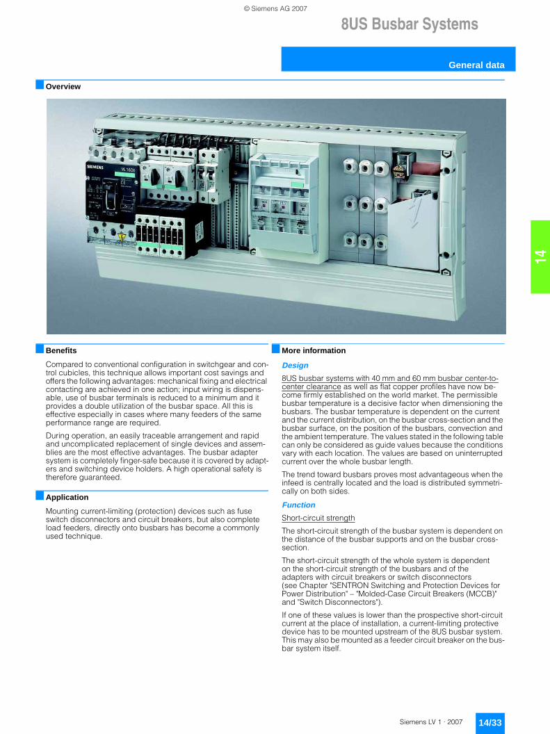
14
8US Busbar Systems
General data
14/33Siemens LV 1 · 2007
■ Overview
■ Benefits
Compared to conventional configuration in switchgear and con-trol cubicles, this technique allows important cost savings and offers the following advantages: mechanical fixing and electrical contacting are achieved in one action; input wiring is dispens-able, use of busbar terminals is reduced to a minimum and it provides a double utilization of the busbar space. All this is effective especially in cases where many feeders of the same performance range are required.
During operation, an easily traceable arrangement and rapid and uncomplicated replacement of single devices and assem-blies are the most effective advantages. The busbar adapter system is completely finger-safe because it is covered by adapt-ers and switching device holders. A high operational safety is therefore guaranteed.
■ Application
Mounting current-limiting (protection) devices such as fuse switch disconnectors and circuit breakers, but also complete load feeders, directly onto busbars has become a commonly used technique.
■ More information
Design
8US busbar systems with 40 mm and 60 mm busbar center-to-center clearance as well as flat copper profiles have now be-come firmly established on the world market. The permissible busbar temperature is a decisive factor when dimensioning the busbars. The busbar temperature is dependent on the current and the current distribution, on the busbar cross-section and the busbar surface, on the position of the busbars, convection and the ambient temperature. The values stated in the following table can only be considered as guide values because the conditions vary with each location. The values are based on uninterrupted current over the whole busbar length.
The trend toward busbars proves most advantageous when the infeed is centrally located and the load is distributed symmetri-cally on both sides.
Function
Short-circuit strength
The short-circuit strength of the busbar system is dependent on the distance of the busbar supports and on the busbar cross-section.
The short-circuit strength of the whole system is dependent on the short-circuit strength of the busbars and of the adapters with circuit breakers or switch disconnectors (see Chapter "SENTRON Switching and Protection Devices for Power Distribution" – "Molded-Case Circuit Breakers (MCCB)" and "Switch Disconnectors").
If one of these values is lower than the prospective short-circuit current at the place of installation, a current-limiting protective device has to be mounted upstream of the 8US busbar system. This may also be mounted as a feeder circuit breaker on the bus-bar system itself.
LV1_14.book Seite 33 Freitag, 26. Januar 2007 11:23 11
© Siemens AG 2007

8US Busbar Systems
General data
14/34 Siemens LV 1 · 2007
14
Technical specifications
Uninterrupted current for busbars, E-Cu bare, at 35 °C ambient temperature according to DIN 43671
1) Reduction of Ui when using certain terminals in the 40-mm system, see Terminals
Characteristic curves
40 mm busbar system 60 mm busbar system
Bar dimensions System Uninterrupted current at a busbar temperature of 65 °C 85 °C 105 °C
mm mm A A A12 × 5 40 + 60 188 248 29515 × 5 40 + 60 222 293 349
20 × 5 60 274 362 43025 × 5 60 327 432 51330 × 5 60 379 500 595
12 × 10 40 + 60 302 398 47420 × 10 60 427 564 67030 × 10 60 573 756 900
Special profile up to 1600 A 60 1020 1020 1600
Technical specifications of the system components
Rated insulation voltage Ui V AC 10001)
Short-circuit strengthof the 8US1 device adapters Current limiting by means of associated circuit breakers/load feeders
up to 50 kAof the busbar systems see Characteristic CurvesMaterialof the 8US1 busbar supports, busbar adapters and device holders Fiberglass-strengthened polyamideColor RAL 7035, light grayTemperature resistanceBusbar supports, busbar adapters, device holders, infeed and covering caps
°C 120
AWG connecting cables °C 105Cover profile °C 110Bottom shells, partitions, edges and blanking covers °C 70ApprovalsBusbar supports, busbar adapters, device holders and terminals UR, CSA
NSE0_01546
2 x 12x5
55
4540
kA
35
302520
400350300250 mm2002
pk
1
A
1 x 12x53
1 Peak current
Distance to busbar support2
pk
5-pole busbar support3
NSE0_01547
2 x 15x5
55
4540
kA
35
302520
400350300250 mm2002
pk
1
A
1 x 15x5
1 Peak current
Spacing for busbar supports2
pk
� pk NSE0_00342b90kA
80
7570
65
60
5550
45
40
35
30600500400300 mm
2
1
700 800 900
20x1012x10
20x512x5
30x10
30x5
T
1
2
Peak current pk
Spacing for busbar supports
LV1_14.book Seite 34 Freitag, 26. Januar 2007 11:23 11
© Siemens AG 2007

14
8US Busbar Systems40 mm Busbar Systems
General data
14/35Siemens LV 1 · 2007
■ Overview
The 40 mm busbar system is used in machinery and plant engineering, in motor control centers and in power distribution systems of the low performance range up to 400 A.
The busbar cross-sections are adapted to the rated currents and are available in the sizes 12 x 5 mm, 12 x 10 mm, 15 x 5 mm and 15 x 10 mm. The basic system is configured without covers. If touch protection is required, this is possible with busbar covers.
An optimized spectrum of busbar adapters and device holders offers numerous adaptation and mounting options. Terminals round off the product range of the 40 mm busbar system.
LV1_14.book Seite 35 Freitag, 26. Januar 2007 11:23 11
© Siemens AG 2007

8US Busbar Systems40 mm Busbar Systems
Base assemblies
14/36 Siemens LV 1 · 2007
14
■ Overview
■ Selection and ordering data
2
3 4
5
1
Flat copper profileBusbar supportCover profile
Inlay partCovering cap2
3
45
1
Description DT Order No. Price per PU
PU (UNIT, SET, M)
PS* PG Weight per PU approx.kg
%() Busbar supportsEnd and intermediate holders forflat copper profiles
8US19 03-3AB00
12 mm x 5 mm,12 mm x 10 mm, 15 mm x 5 mm,15 mm x 10 mm 3-pole, with inside fixing (PU = 2 busbar supports including inlay parts for bar thickness 5 mm and lateral finger-safe covering caps)
A 8US19 03-3AB00 1 1 unit 103 0.184
8US19 03-5AA00
5-pole 12 mm x 5 mm and 12 mm x 10 mm with inside fixing
L1–L3 + N + PE/N
A 8US19 03-5AA00 1 1 unit 103 0.137
$ Busbar coppers (flat profile, approx. 2 m long, bare, according to EN 12167)12 mm × 5 mm B 8WC5 023 1 1 unit 103 1.10015 mm × 5 mm B 8WC5 021 1 1 unit 103 1.550
& Cover profiles for busbars
Cover profile
12 mm × 5 mm 1000 mm long
A 8US19 22-2CA00 1 10 units 103 0.200
15 mm × 5 mm 1000 mm long
A 8US19 22-2AA00 1 10 units 103 0.156
* You can order this quantity or a multiple thereof.
LV1_14.book Seite 36 Freitag, 26. Januar 2007 11:23 11
© Siemens AG 2007

14
8US Busbar Systems40 mm Busbar Systems
Supply and connection technologies
14/37Siemens LV 1 · 2007
■ Overview
■ Selection and ordering data
1) When using the 8US19 03-3AB00 busbar support in combination with the 8US19 21-2.D0. or 8US19 21-2.C0. terminals, Ui is reduced to 690 V.
2) When using the 8US19 03-5AA00 busbar support with a 12 mm x 10 mm busbar, Ui is reduced toa) 690 V when using the 8US19 21-2.A0. or 8US19 21-2.B0.
terminalsb) 480 V when using the 8US19 21-2.C0. or 8US19 21-2.D0.
terminals.
Description Conductor cross-section
DT Order No. Price per PU
PU (UNIT, SET, M)
PS* PG Weight per PU approx.
mm2 kg
Terminals for circular conductors1)2)
5 mm bar thickness
Terminals
12 mm × 5 mm, 15 mm × 5 mm 1.5 ... 16 } 8US19 21-2AA00 100 100 units 103 0.1004 ... 35 } 8US19 21-2AB00 1 50 units 103 0.04616 ... 70 } 8US19 21-2AD00 1 50 units 103 0.07216 ... 120 } 8US19 21-2AC00 1 50 units 103 0.107
1.5 ... 16 } 8US19 21-2AA01 1 15 units 103 0.0204 ... 35 } 8US19 21-2AB01 1 15 units 103 0.02016 ... 70 } 8US19 21-2AD01 1 15 units 103 0.02016 ... 120 } 8US19 21-2AC01 1 15 units 103 0.020
10 mm bar thickness12 mm × 10 mm, 15 mm × 10 mm 1.5 ... 16 } 8US19 21-2BA00 1 100 units 103 0.020
4 ... 35 } 8US19 21-2BB00 1 50 units 103 0.04016 ... 70 } 8US19 21-2BD00 1 50 units 103 0.07016 ... 120 } 8US19 21-2BC00 1 50 units 103 0.100
1.5 ... 16 } 8US19 21-2BA01 1 15 units 103 0.0204 ... 35 } 8US19 21-2BB01 1 15 units 103 0.04016 ... 70 } 8US19 21-2BD01 1 15 units 103 0.07016 ... 120 } 8US19 21-2BC01 1 15 units 103 0.100
Covering caps for terminals for circular conductors (attachment to busbars)for terminals up to 120 mm2
} 8US19 22-1GA00 1 10 units 103 0.126
200 mm long, 84 mm wide
* You can order this quantity or a multiple thereof.
LV1_14.book Seite 37 Freitag, 26. Januar 2007 11:23 11
© Siemens AG 2007

8US Busbar Systems40 mm Busbar Systems
Busbar adapters and device holders
14/38 Siemens LV 1 · 2007
14
■ Overview
■ Selection and ordering data
For copper busbars according to DIN 46433, width: 12 mm and 15 mm, circumference: 5 mm and 10 mm
Busbar device adapters
Number of mount-ing rails (35 mm)
Rated current
Con-nection lead
Adap-ter length
Adap-ter width
Rated volt-age
DT Order No. Price per PU
PU (UNIT, SET, M)
PS* PG Weight per PU approx.
A AWG mm mm V kgFor SIRIUSSize S00/S0Circuit breaker 1 25 12 121 45 690 } 8US10 51-5DJ07 1 1 unit 103 0.106
Circuit break-ers + lateral auxiliary switch
1 25 12 121 55 690 } 8US10 61-5DJ07 1 1 unit 103 0.119
Direct start load feeder
Contactors + overload relay
1 25 12 139 45 690 } 8US10 51-5DK07 1 1 unit 103 0.164
Direct start load feeders
1 25 12 182 45 690 } 8US10 51-5DM07 1 1 unit 103 0.184
Reversing feeder adapter
1 25 12 182 45 690 } 8US10 51-5DM07 1 1 unit 103 0.184
+ +Device holders 1 -- -- 182 45 -- } 8US10 50-5AM00 1 1 unit 103 0.182+ +Link wedges (2 units needed for attachment)
-- -- -- -- -- -- } 8US19 98-1AA00 100 100 units 103 0.100
Size S00 - Cage ClampDirect start load feeders
1 12.5 14 182 45 690 } 8US10 51-5CM47 1 1 unit 103 0.193
Size S2
Reversing feeders
Circuit breaker 1 56 8 139 55 690 } 8US10 61-5FK08 1 1 unit 103 0.231
Circuit break-ers + lateral auxiliary switch
1 56 8 139 55 690 } 8US10 61-5FK08 1 1 unit 103 0.231
Contactors + overload relay
1 56 8 182 55 690 } 8US10 61-5FM08 1 1 unit 103 0.278
Direct start load feeders
1 56 8 242 55 690 } 8US10 61-5FP08 1 1 unit 103 0.308
Reversing feeder adapter
1 56 8 242 55 690 } 8US10 61-5FP08 1 1 unit 103 0.308
+ +Device holders1)
-- -- -- 242 54 -- } 8US10 60-5AP00 1 1 unit 103 0.244
+ +Link wedges (2 units needed for attachment)
-- -- -- -- -- -- } 8US19 98-1AA00 100 100 units 103 0.100
* You can order this quantity or a multiple thereof.
LV1_14.book Seite 38 Freitag, 26. Januar 2007 11:23 11
© Siemens AG 2007

14
8US Busbar Systems40 mm Busbar Systems
Busbar adapters and device holders
14/39Siemens LV 1 · 2007
1) Spacer and fixing screw for reversing contactor are included in the delivery.
2)≤ 400 V max. 50 kA, 400 V ... 460 V max. 25 kA.
3) Up to 525 V max. 30 kA, 525 V ... 690 V max. 12 kA.4) Observe the short-circuit strength of the busbar system.
Short-circuit strength > 50 kA on request.5) Can be used simultaneously as incoming unit and outgoing unit.
Size S3Circuit breaker -- 100 Bars 182 70 up to
4602)} 8US11 11-4SM00 1 1 unit 103 0.541
Circuit breaker 1 100 4 182 72 up to 6903)
} 8US10 11-4TM00 1 1 unit 103 0.478
8US10 11-4SL01
For 3VF circuit breakers3VF3 205 Bars 175 108 690 A 8US10 11-4SB00 1 1 unit 103 0.500
For 3VL circuit breakers4)
3VL1 -- 160 Bars 175 108 690 A 8US10 11-4SL01 1 1 unit 103 0.585
3VL2 -- 160 Bars 175 108 690 A 8US10 11-4SL01 1 1 unit 103 0.585
8US10 50-5RM07
With terminals (at top) for any arrangement of components1.5 mm2 ... 4 mm2
1 25 -- 139 45 690 A 8US10 50-5RK07 1 1 unit 103 0.149
1.5 mm2 ... 4 mm2
1 25 -- 182 45 690 A 8US10 50-5RM07 1 1 unit 103 0.177
8US10 60-5AK00
16 mm2 (top) and 35 mm2 (bottom)5)
1 80 -- 139 54 690 A 8US10 60-5AK00 1 1 unit 103 0.295
8US10 60-5AM00
Device holders for lateral attachment tobusbar device adapters of the same lengthDevice holder 1 -- -- 139 45 -- A 8US10 50-5AK00 1 1 unit 103 0.149
Device holder 1 -- -- 139 55 -- A 8US10 60-5AK08 1 1 unit 103 0.162
Device holder 1 -- -- 182 45 -- } 8US10 50-5AM00 1 1 unit 103 0.182
Device holder 1 -- -- 182 55 -- } 8US10 60-5AM00 1 1 unit 103 0.197
Device holder -- -- -- 242 54 -- } 8US10 60-5AP00 1 1 unit 103 0.244
Link wedges (2 units needed for attachment)
-- -- -- -- -- -- } 8US19 98-1AA00 100 100 units 103 0.100
Side modules for extending busbar device adapters and device holders of the same lengthSide modules -- -- -- 139 13.5 -- A 8US19 98-2BK00 1 4 units 103 0.023
Side modules -- -- -- 182 13.5 -- A 8US19 98-2BM00 1 4 units 103 0.036
Busbar device adapters
Number of mount-ing rails (35 mm)
Rated current
Con-nection lead
Adap-ter length
Adap-ter width
Rated volt-age
DT Order No. Price per PU
PU (UNIT, SET, M)
PS* PG Weight per PU approx.
A AWG mm mm V kg
* You can order this quantity or a multiple thereof.
LV1_14.book Seite 39 Freitag, 26. Januar 2007 11:23 11
© Siemens AG 2007

8US Busbar Systems40 mm Busbar Systems
Busbar adapters and device holders
14/40 Siemens LV 1 · 2007
14
3NP4 fuse switch disconnectors for snapping onto 40 mm busbar systems1)
For all fuse switch disconnectors with flat connector connection, the appropriate cable lug covers (3NY7 101 to 3NY7 141) must be used for finger-safe cover according to BGV A2, see Acces-sories. 1) For mounting on only 5 mm thick busbars, a busbar thickness compensa-
tor is required for 3NP42 and 3NP43; see Accessories. 2) Fuse links see Catalog ET B1 "BETA low-voltage circuit protection".3) Insert silver-plated isolating links.4) 125/160 A only possible with 21-mm wide 3NY1 822 (125 A) and 3NY1 824
(160 A) fuse links, see Accessories.5) Corresponds to size 00 with a maximum width of 21 mm
(according to IEC 60269-2-1 and DIN 43620).
Rated uninter-rupted current Iu
Connection types (on both sides)
For fuse links ac-cording to DIN 43620 2)
For iso-lating links3)
DT Degree of protection IP00, without fuse links, without isolating links, with terminal screws
PU (UNIT, SET, M)
PS* PG Weight per PU approx.
Connec-tion
For conductor cross-section
Order No. Price per PU
A mm2 Size Size kgWith adapter, deep, e.g. for mounting in ALPHA meter cubicles (ALPHA 400-ZS) and ALPHA distribution boards (STAB/SIKUS)1604) Box
terminal1.5 ... 50
Connection, top
0005) 00 A 3NP40 15-0CK01 1 1 unit 103 0.952
Connection, bottom
A 3NP40 15-0CJ01 1 1 unit 103 0.970
160 Flat connector
Up to 2 × 70 (M8)
Connection, top
00 and 000 00 A 3NP40 75-0CE01 1 1 unit 103 1.210
Connection, bottom
A 3NP40 75-0CF01 1 1 unit 103 1.244
Box terminal
2.5 ... 70 or 2 × 2.5 ... 16Connection, top
00 and 000 00 A 3NP40 75-0CK01 1 1 unit 103 1.290
Connection, bottom
A 3NP40 75-0CJ01 1 1 unit 103 1.274
With adapter, flat, according to DIN 43620 Part 6, for general applications and ALPHA distribution boards (STAB/SIKUS)1604) Box
terminal1.5 ... 50
Connection, top
0005) 00 A 3NP40 15-1CK01 1 1 unit 103 0.892
Connection, bottom
B 3NP40 15-1CJ01 1 1 unit 103 0.888
160 Flat connector
Up to 2 × 70 (M8)Connection, top
00 and 000 00 and 000
A 3NP40 75-1CE01 1 1 unit 103 1.186
Connection, bottom
A 3NP40 75-1CF01 1 1 unit 103 1.189
Box terminal
2.5 ... 70 or 2 × 2.5 ... 16Connection, top
00 and 000 00 and 000
A 3NP40 75-1CK01 1 1 unit 103 1.261
Connection, bottom
A 3NP40 75-1CJ01 1 1 unit 103 1.213
250 Flat connector
Up to 240 (M10)
Connection from bottom or top
1 and 0 1 and 0 A 3NP42 75-1CG01 1 1 unit 103 3.719
* You can order this quantity or a multiple thereof.
LV1_14.book Seite 40 Freitag, 26. Januar 2007 11:23 11
© Siemens AG 2007

14
8US Busbar Systems40 mm Busbar Systems
Busbar adapters and device holders
14/41Siemens LV 1 · 2007
3NP4 fuse switch disconnectors with fuse monitoring by SIRIUS circuit breakers1)2)
for snapping onto 40 mm busbar systems3)
For all fuse switch disconnectors with flat connector connection, the appropriate cable lug covers (3NY7 101 to 3NY7 141) must be used for finger-safe cover according to BGV A2, see Accessories. 1) SIRIUS circuit breakers, as standard with auxiliary switches 1 NO + 1 NC.2) For 3NP40 7 with output socket for auxiliary switches, the signal cable
must be ordered separately; see Accessories. For 3NP41 to 3NP44, the auxiliary switch must be connected with a 2.8 mm × 0.5 mm flat connector to DIN 46244-A.
3) For mounting on only 5 mm thick busbars, a busbar thickness compensator is required for 3NP42 and 3NP43; see Accessories.
4) Fuse links see Catalog ET B1 "BETA low-voltage circuit protection".5) Insert silver-plated isolating links.
Rated unin-terrupt-ed cur-rent Iu
Connection types (on both sides)
For fuse links ac-cording to DIN 43620 4)
For iso-lating links5)
DT Degree of protection IP00, without fuse links, withoutisolating links, with terminal screws
PU (UNIT, SET, M)
PS* PG Weight per PU approx.
Connec-tion
for conduc-tor cross-section
Order No. Price per PU
A mm2 Size Size kgWith adapter, deep, e.g. for mounting in ALPHA meter cubicles (ALPHA 400-ZS) and ALPHA distribution boards (STAB/SIKUS)160 Flat
connectorup to 2 × 70 (M8)
Connection, top
00 and 000 00 B 3NP40 75-0FE01 1 1 unit 103 1.812
Connection, bottom
B 3NP40 75-0FF01 1 1 unit 103 1.780
Boxterminal
2.5 ... 70 or2 × 2.5 ... 16Connection, top
00 and 000 00 B 3NP40 75-0FK01 1 1 unit 103 1.820
Connection, bottom
B 3NP40 75-0FJ01 1 1 unit 103 1.831
With adapter, flat, according to DIN 43620 Part 6, for general applications and ALPHA distribution boards (STAB/SIKUS)160 Flat
connectorUp to 2 × 70 (M8)
3NP40 75-1FF01
Connection, top
00 and 000 00 and 000
B 3NP40 75-1FE01 1 1 unit 103 1.616
Connection, bottom
B 3NP40 75-1FF01 1 1 unit 103 1.620
Box terminal
2.5 ... 70 or2 × 2.5 ... 16Connection, top
00 and 000 00 and 000
B 3NP40 75-1FK01 1 1 unit 103 1.717
Connection, bottom
B 3NP40 75-1FJ01 1 1 unit 103 1.630
250 Flat connector
Up to 240 (M10)
Connection from top or bottom
1 and 0 1 and 0 A 3NP42 75-1FG01 1 1 unit 103 4.210
* You can order this quantity or a multiple thereof.
LV1_14.book Seite 41 Freitag, 26. Januar 2007 11:23 11
© Siemens AG 2007
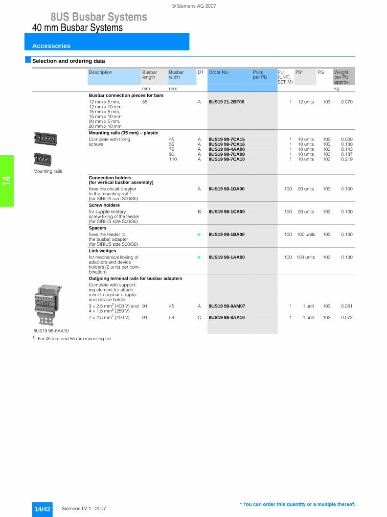
8US Busbar Systems40 mm Busbar Systems
Accessories
14/42 Siemens LV 1 · 2007
14
■ Selection and ordering data
1) For 45 mm and 55 mm mounting rail.
Description Busbar length
Busbar width
DT Order No. Price per PU
PU (UNIT, SET, M)
PS* PG Weight per PU approx.
mm mm kg
Busbar connection pieces for bars12 mm x 5 mm, 12 mm x 10 mm, 15 mm x 5 mm, 15 mm x 10 mm, 20 mm x 5 mm, 20 mm x 10 mm
55 A 8US19 21-2BF00 1 12 units 103 0.070
Mounting rails
Mounting rails (35 mm) – plasticComplete with fixing screws
45 A 8US19 98-7CA15 1 10 units 103 0.00955 A 8US19 98-7CA16 1 10 units 103 0.10072 A 8US19 98-4AA00 1 10 units 103 0.14390 A 8US19 98-7CA08 1 10 units 103 0.187110 A 8US19 98-7CA10 1 10 units 103 0.219
Connection holders(for vertical busbar assembly)fixes the circuit breaker to the mounting rail1) (for SIRIUS size S00/S0)
A 8US19 98-1DA00 100 20 units 103 0.100
Screw holdersfor supplementary screw fixing of the feeder (for SIRIUS size S00/S0)
B 8US19 98-1CA00 100 20 units 103 0.100
Spacersfixes the feeder to the busbar adapter (for SIRIUS size S00/S0)
} 8US19 98-1BA00 100 100 units 103 0.100
Link wedgesfor mechanical linking of adapters and device holders (2 units per com-bination)
} 8US19 98-1AA00 100 100 units 103 0.100
Outgoing terminal rails for busbar adapters
8US19 98-8AA10
Complete with support-ing element for attach-ment to busbar adapter and device holder3 × 2.5 mm2 (400 V) and 4 × 1.5 mm2 (250 V)
91 45 A 8US19 98-8AM07 1 1 unit 103 0.061
7 × 2.5 mm2 (400 V) 91 54 C 8US19 98-8AA10 1 1 unit 103 0.072
* You can order this quantity or a multiple thereof.
LV1_14.book Seite 42 Freitag, 26. Januar 2007 11:23 11
© Siemens AG 2007

14
8US Busbar Systems60 mm Busbar Systems
General data
14/43Siemens LV 1 · 2007
■ Overview
The 60 mm busbar system is used preferably in control cabinet installation, in motor control centers and in power distribution systems of the medium power range (630 A) and top perfor-mance range (1600 A, special profile).
The 60 mm busbar system can be used as a basic system without covers, as a partly compartmented system or as a fully compartmented system with bottom shell. The busbar cross-sections are available in the sizes 12 x 5 mm to 30 x 10 mm and as a special profile.
Busbar device adapters for SIRIUS, 3VL circuit breakers, 3KA and 3KL switch disconnectors, 3NP5 fuse switch disconnectors and 3NP4 directly mountable fuse switch disconnectors offer numerous options for configuring this busbar system. Incoming feeders, terminals and other accessories open up a large range of application.
Busbars with a special profile are suitable for applications upto 1600 A. All components of the 60 mm busbar system can be fitted.
LV1_14.book Seite 43 Freitag, 26. Januar 2007 11:23 11
© Siemens AG 2007

8US Busbar Systems60 mm Busbar Systems
Base assemblies up to 630 A
14/44 Siemens LV 1 · 2007
14
■ Overview
■ Selection and ordering data
Description DT Order No. Price per PU
PU (UNIT, SET, M)
PS* PG Weight per PU approx.kg
8US19 23-5AA00
% Busbar supportsEnd and intermediate holders for flat copper profiles 12 mm x 5 mm, 12 mm x 10 mm, 15 mm x 5 mm, 15 mm x 10 mm, 20 mm x 5 mm, 20 mm x 10 mm, 25 mm x 5 mm, 25 mm x 10 mm, 30 mm x 5 mm, 30 mm x 10 mm2-pole, with outside fixing A 8US19 23-5AA00 1 10 units 103 0.200
8US19 23-3AA01
3-pole, with outside fixing L1–L3 A 8US19 23-2AA01 1 10 units 103 0.200
3-pole, with inside fixing L1–L3 A 8US19 23-3AA01 1 10 units 103 0.200
4-pole, with inside fixing L1–L3 + PE/N
A 8US19 23-4AA00 1 10 units 103 0.269
5SH3 506
N-/PE busbar supports for flat copper profiles 12 mm x 5 mm, 12 mm x 10 mm, 15 mm x 5 mm, 15 mm x 10 mm, 20 mm x 5 mm, 20 mm x 10 mm, 25 mm x 5 mm, 25 mm x 10 mm, 30 mm x 5 mm, 30 mm x 10 mmAttachment to 8US19 23-2AA01 or independent installation
A 5SH3 506 1 4 units 016 0.060
8US19 22-1AC005SH3 534
& End coversfor covering unterminated busbar endsfor 8US19 23-2AA01 or 8US19 23-3AA01
L1–L3 A 8US19 22-1AC00 1 10 units 103 0.020
4-pole, for 8US19 23-4AA00 (1 pack = 2 units, (1x right, 1x left))
L1–L3 + PE/N
A 8US19 22-1AB00 1 1 unit 103 0.055
for 5SH3 532 holderHeight 230 mm (3-pole) A 5SH3 533 1 4 units 016 0.038
Height 290 mm (4-pole or 3-pole + cable duct), (1 pack = 2 units, (1x right, 1x left))
A 5SH3 534 1 4 units 016 0.048
* You can order this quantity or a multiple thereof.
LV1_14.book Seite 44 Freitag, 26. Januar 2007 11:23 11
© Siemens AG 2007
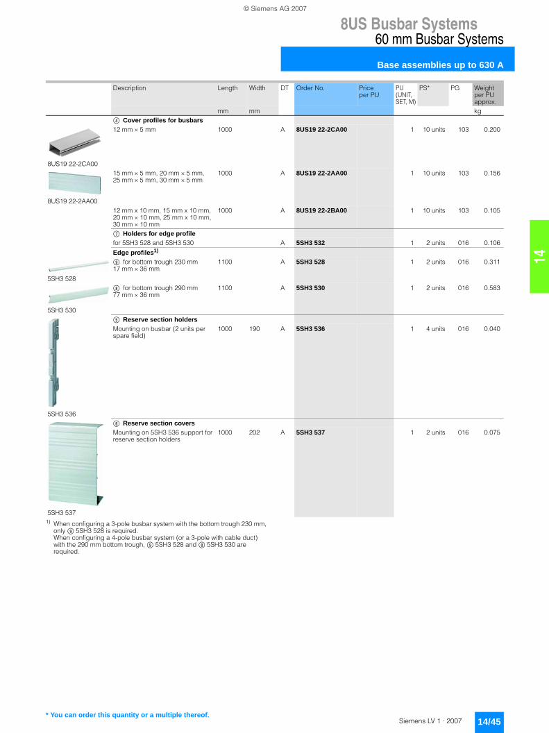
14
8US Busbar Systems60 mm Busbar Systems
Base assemblies up to 630 A
14/45Siemens LV 1 · 2007
1) When configuring a 3-pole busbar system with the bottom trough 230 mm, only - 5SH3 528 is required. When configuring a 4-pole busbar system (or a 3-pole with cable duct) with the 290 mm bottom trough, - 5SH3 528 and , 5SH3 530 are required.
Description Length Width DT Order No. Price per PU
PU (UNIT, SET, M)
PS* PG Weight per PU approx.
mm mm kg( Cover profiles for busbars
8US19 22-2CA00
12 mm × 5 mm 1000 A 8US19 22-2CA00 1 10 units 103 0.200
8US19 22-2AA00
15 mm × 5 mm, 20 mm × 5 mm, 25 mm × 5 mm, 30 mm × 5 mm
1000 A 8US19 22-2AA00 1 10 units 103 0.156
12 mm x 10 mm, 15 mm x 10 mm, 20 mm × 10 mm, 25 mm x 10 mm, 30 mm × 10 mm
1000 A 8US19 22-2BA00 1 10 units 103 0.105
+ Holders for edge profilefor 5SH3 528 and 5SH3 530 A 5SH3 532 1 2 units 016 0.106
Edge profiles1)
5SH3 528
- for bottom trough 230 mm17 mm × 36 mm
1100 A 5SH3 528 1 2 units 016 0.311
5SH3 530
, for bottom trough 290 mm77 mm × 36 mm
1100 A 5SH3 530 1 2 units 016 0.583
5SH3 536
) Reserve section holdersMounting on busbar (2 units per spare field)
1000 190 A 5SH3 536 1 4 units 016 0.040
5SH3 537
* Reserve section coversMounting on 5SH3 536 support for reserve section holders
1000 202 A 5SH3 537 1 2 units 016 0.075
* You can order this quantity or a multiple thereof.
LV1_14.book Seite 45 Freitag, 26. Januar 2007 11:23 11
© Siemens AG 2007
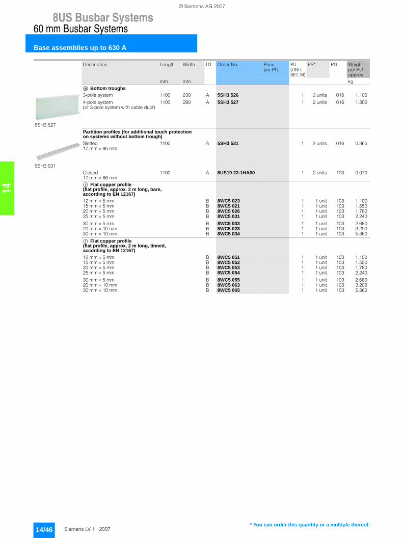
8US Busbar Systems60 mm Busbar Systems
Base assemblies up to 630 A
14/46 Siemens LV 1 · 2007
14
Description Length Width DT Order No. Price per PU
PU (UNIT, SET, M)
PS* PG Weight per PU approx.
mm mm kg. Bottom troughs
5SH3 527
3-pole system 1100 230 A 5SH3 526 1 2 units 016 1.100
4-pole system (or 3-pole system with cable duct)
1100 290 A 5SH3 527 1 2 units 016 1.300
Partition profiles (for additional touch protection on systems without bottom trough)
5SH3 531
Slotted17 mm × 86 mm
1100 A 5SH3 531 1 2 units 016 0.365
Closed17 mm × 86 mm
1100 A 8US19 22-1HA00 1 2 units 103 0.070
$ Flat copper profile(flat profile, approx. 2 m long, bare, according to EN 12167)12 mm × 5 mm B 8WC5 023 1 1 unit 103 1.10015 mm × 5 mm B 8WC5 021 1 1 unit 103 1.55020 mm × 5 mm B 8WC5 026 1 1 unit 103 1.78025 mm × 5 mm B 8WC5 031 1 1 unit 103 2.240
30 mm × 5 mm B 8WC5 033 1 1 unit 103 2.68020 mm × 10 mm B 8WC5 028 1 1 unit 103 3.20030 mm × 10 mm B 8WC5 034 1 1 unit 103 5.360
$ Flat copper profile (flat profile, approx. 2 m long, tinned, according to EN 12167)12 mm × 5 mm B 8WC5 051 1 1 unit 103 1.10015 mm × 5 mm B 8WC5 052 1 1 unit 103 1.55020 mm × 5 mm B 8WC5 053 1 1 unit 103 1.78025 mm × 5 mm B 8WC5 054 1 1 unit 103 2.240
30 mm × 5 mm B 8WC5 055 1 1 unit 103 2.68020 mm × 10 mm B 8WC5 063 1 1 unit 103 3.20030 mm × 10 mm B 8WC5 065 1 1 unit 103 5.360
* You can order this quantity or a multiple thereof.
LV1_14.book Seite 46 Freitag, 26. Januar 2007 11:23 11
© Siemens AG 2007

14
8US Busbar Systems60 mm Busbar Systems
Base assemblies up to 1600 A
14/47Siemens LV 1 · 2007
■ Overview
■ Selection and ordering data
3
1 2
1
3
Flat copper profileBusbar supportEnd cover
2
Description DT Order No. Price per PU
PU (UNIT, SET, M)
PS* PG Weight per PU approx.kg
Busbar supports3-pole, end and intermediate holder with finger-safe busbar cover(1 pack = 2 busbar supports + finger-safe end covers)
L1–L3 A 8US19 43-3AA00 1 1 set 103 1.310
Flat copper profile (approx. 2.4 m long, tinned)
8US19 48-2AA00
special profile up to 1600 A 720 mm2 A 8US19 48-2AA00 1 1 unit 103 15.360
Cover profiles
for busbar copper 1000 mm long A 8US19 22-2DA00 1 5 units 103 0.200
* You can order this quantity or a multiple thereof.
LV1_14.book Seite 47 Freitag, 26. Januar 2007 11:23 11
© Siemens AG 2007

8US Busbar Systems60 mm Busbar Systems
Supply and connection technologies
14/48 Siemens LV 1 · 2007
14
■ Overview
■ Selection and ordering data
Description Conductor cross-section
DT Order No. Price per PU
PU (UNIT, SET, M)
PS* PG Weight per PU approx.
mm2 kgInfeeds
8US19 21-1AA00
Terminal plate with cover3-pole,200 mm long, 54 mm wide
6 ... 50 D 8US19 21-1BA00 1 1 unit 103 0.397
3-pole,200 mm long, 81 mm wide
35 ... 120 A 8US19 21-1AA00 1 1 unit 103 0.607
Outgoing modules for PE/NConnection module for 4-pole (PE/N) up to 16 mm must be attached to an adapter/device holder
242 mm long, 18 mm wide
A 8US12 00-0AA00 1 1 unit 103 0.142
5SH3 535
SR60 connecting terminal plates3-pole(shown without cover)
150 ... 300 A 5SH3 535 1 1 unit 016 1.657
Terminals for circular conductors5 mm bar thickness1)
Terminals
12 mm × 5 mm, 15 mm × 5 mm, 20 mm × 5 mm, 25 mm × 5 mm, 30 mm × 5 mm
1.5 ... 16 } 8US19 21-2AA00 100 100 units 103 0.1004 ... 35 } 8US19 21-2AB00 1 50 units 103 0.04616 ... 70 } 8US19 21-2AD00 1 50 units 103 0.07216 ... 120 } 8US19 21-2AC00 1 50 units 103 0.107
1.5 ... 16 } 8US19 21-2AA01 1 15 units 103 0.0204 ... 35 } 8US19 21-2AB01 1 15 units 103 0.02016 ... 70 } 8US19 21-2AD01 1 15 units 103 0.02016 ... 120 } 8US19 21-2AC01 1 15 units 103 0.020
20 mm × 5 mm, 25 mm × 5 mm, 30 mm × 5 mm
95 ... 185 } 8US19 41-2AA01 1 6 units 103 0.315150 ... 300 } 8US19 41-2AA02 1 3 units 103 0.425
1) Cannot be used on a special profile up to 1600 A.
* You can order this quantity or a multiple thereof.
LV1_14.book Seite 48 Freitag, 26. Januar 2007 11:23 11
© Siemens AG 2007

14
8US Busbar Systems60 mm Busbar Systems
Supply and connection technologies
14/49Siemens LV 1 · 2007
1) Only for 20 mm × 5 mm, 20 mm × 10 mm, 25 mm × 5 mm, 25 mm × 10 mm, 30 mm × 5 mm and 30 mm × 10 mm.
10 mm busbar thickness
Terminals
12 mm × 10 mm, 15 mm × 10 mm, 20 mm × 10 mm, 25 mm × 10 mm, 30 mm × 10 mm
1.5 ... 16 } 8US19 21-2BA00 1 100 units 103 0.0204 ... 35 } 8US19 21-2BB00 1 50 units 103 0.04016 ... 70 } 8US19 21-2BD00 1 50 units 103 0.07016 ... 120 } 8US19 21-2BC00 1 50 units 103 0.100
1.5 ... 16 } 8US19 21-2BA01 1 15 units 103 0.0204 ... 35 } 8US19 21-2BB01 1 15 units 103 0.04016 ... 70 } 8US19 21-2BD01 1 15 units 103 0.07016 ... 120 } 8US19 21-2BC01 1 15 units 103 0.100
20 mm × 10 mm, 25 mm × 10 mm, 30 mm × 10 mm
95 ... 185 } 8US19 41-2AA01 1 6 units 103 0.315150 ... 300 } 8US19 41-2AA02 1 3 units 103 0.425
Covering caps for terminals for circular conductors (attachment to busbar)
8US19 22-1GA00
for terminals up to 120 mm2 200 mm long, 84 mm wide
} 8US19 22-1GA00 1 10 units 103 0.126
for terminals up to 300 mm2 1)
200 mm long, 270 mm wide
} 8US19 22-1GA02 1 1 unit 103 0.696
Terminalsfor cable lugs up to 240 mm2, 10 mm bar thickness
(bolts threaded M10)
A 8US19 41-2AC00 1 6 units 103 0.368
for copper bars or laminated conductors20 mm × 5 mm, 20 mm × 10 mm, 25 mm × 5 mm, 25 mm × 10 mm, 30 mm × 5 mm, 30 mm × 10 mm
A 8US19 41-2BB00 1 6 units 103 0.307
for 2 × 40 mm × 10 mm A 8US19 41-2BA00 1 3 units 103 0.824
Description Conductor cross-section
DT Order No. Price per PU
PU (UNIT, SET, M)
PS* PG Weight per PU approx.
mm2 kg
* You can order this quantity or a multiple thereof.
LV1_14.book Seite 49 Freitag, 26. Januar 2007 11:23 11
© Siemens AG 2007
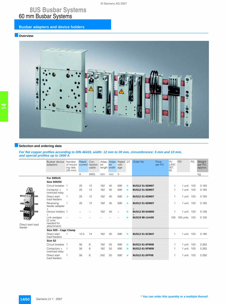
8US Busbar Systems60 mm Busbar Systems
Busbar adapters and device holders
14/50 Siemens LV 1 · 2007
14
■ Overview
■ Selection and ordering data
For flat copper profiles according to DIN 46433, width: 12 mm to 30 mm, circumference: 5 mm and 10 mm, and special profiles up to 1600 A
Busbar device adapters
Number of mount-ing rails (35 mm)
Rated current
Con-nection cable
Adap-ter length
Adap-ter width
Rated volt-age
DT Order No. Price per PU
PU (UNIT, SET, M)
PS* PG Weight per PU approx.
A AWG mm mm V kgFor SIRIUSSize S00/S0
Direct start load feeder
Circuit breaker 1 25 12 182 45 690 } 8US12 51-5DM07 1 1 unit 103 0.183
Contactor + overload relay
1 25 12 182 45 690 } 8US12 51-5DM07 1 1 unit 103 0.183
Direct start load feeders
1 25 12 182 45 690 } 8US12 51-5DM07 1 1 unit 103 0.183
Reversing feeder adapter
1 25 12 182 45 690 } 8US12 51-5DM07 1 1 unit 103 0.183
+ +Device holders 1 -- -- 182 45 -- } 8US12 50-5AM00 1 1 unit 103 0.158+ +Link wedges (2 units needed for attachment)
-- -- -- -- -- -- } 8US19 98-1AA00 100 100 units 103 0.100
Size S00 - Cage ClampDirect start load feeders
1 12.5 14 182 45 690 } 8US12 51-5CM47 1 1 unit 103 0.190
Size S2Circuit breaker 1 56 8 182 55 690 } 8US12 61-5FM08 1 1 unit 103 0.263
Contactors + overload relay
1 56 8 182 55 690 } 8US12 61-5FM08 1 1 unit 103 0.263
Direct start load feeders
1 56 8 242 55 690 } 8US12 61-5FP08 1 1 unit 103 0.292
* You can order this quantity or a multiple thereof.
LV1_14.book Seite 50 Freitag, 26. Januar 2007 11:23 11
© Siemens AG 2007

14
8US Busbar Systems60 mm Busbar Systems
Busbar adapters and device holders
14/51Siemens LV 1 · 2007
Reversing feeders
Reversing feeder adapter
1 56 8 242 55 690 } 8US12 61-5FP08 1 1 unit 103 0.292
+ +Device holders1)
-- -- -- 242 54 -- } 8US12 60-5AP00 1 1 unit 103 0.243
+ +Link wedges (2 units needed for attachment)
-- -- -- -- -- -- } 8US19 98-1AA00 100 100 units 103 0.100
Size S3Circuit breaker -- 100 Bars 182 70 up to
4603)} 8US11 11-4SM00 1 1 unit 103 0.541
Circuit breakers2)
1 100 4 182 72 up to 6904)
A 8US12 11-4TM00 1 1 unit 103 0.498
For 3VF circuit breakers
8US12 11-4SB00 with 3VF3
3VF3 200 Bars 175 108 690 A 8US12 11-4SB00 1 1 unit 103 0.580
3VF45) Mounting plate
200 Termi-nals 70 mm2
254 108 690 A 8US12 10-4AA04 1 1 unit 103 1.147
3VF46), 3VF56) Mounting plate
630 M10 stud terminal
320 185 690 A 8US12 10-4AF00 1 1 unit 103 2.769+
A 8US19 27-4AF00 1 1 unit 103 0.501
For 3VL circuit breakers7)
8US12 11-4SL01
3VL1 -- 160 Bars 175 108 690 A 8US12 11-4SL01 1 1 unit 103 0.597
3VL2 -- 160 Bars 175 108 690 A 8US12 11-4SL01 1 1 unit 103 0.597
3VL3 -- 250 Bars 175 108 690 A 8US12 11-4SL00 1 1 unit 103 0.662
3VL1 to 3VL4 and also with RCD module
-- 400 M10 stud terminal
320 184 690 A 8US12 10-4AF00 1 1 unit 103 2.769+
A 8US19 27-4AF01 1 1 unit 103 0.575
For switch disconnectors3KA526), 3KA536), 3KL526), 3KL536)
-- 630 M10 stud terminal
320 184 690 A 8US12 10-4AF00 1 1 unit 103 2.769
3KA556), 3KA576), 3KA586), 3KL556), 3KL576)
-- 630 M10 stud terminal
320 250 690 A 8US12 10-4AG00 1 1 unit 103 3.060
Busbar device adapters
Number of mount-ing rails (35 mm)
Rated current
Con-nection cable
Adap-ter length
Adap-ter width
Rated volt-age
DT Order No. Price per PU
PU (UNIT, SET, M)
PS* PG Weight per PU approx.
A AWG mm mm V kg
1) Spacer and fixing screw for reversing contactor are included in the delivery.
2) According to UL508 rated current 80 A.3)
≤ 400 V max. 50 kA, 400 V ... 460 V max. 25 kA.4) Up to 525 V max. 30 kA, 525 V ... 690 V max. 12 kA.5) Without connecting cables. The connecting cable between adapter and
device should be manufactured in accordance with the rated current as a round cable, e.g. H07V-R, bared at both ends for tunnel terminals
6) Without connecting cables. The connecting cable between adapter and device should be manufactured in accordance with the rated current as a round cable, e.g. H07V-R with cable lug, or as a ribbon cable for a M10 stud terminal.
7) Observe the short-circuit strength of the busbar system.Short-circuit strength > 50 kA on request.
* You can order this quantity or a multiple thereof.
LV1_14.book Seite 51 Freitag, 26. Januar 2007 11:23 11
© Siemens AG 2007

8US Busbar Systems60 mm Busbar Systems
Busbar adapters and device holders
14/52 Siemens LV 1 · 2007
14
1) Without connecting cables. The connecting cable between adapter and device should be manufactured in accordance with the rated current as a round cable, e.g. H07V-R with cable lug, or as a ribbon cable for a M10 stud terminal.
2) Without connecting cables. The connecting cable between adapter and device should be manufactured in accordance with the rated current as a round cable, e.g. H07V-R, bared at both ends for tunnel terminals
For 3NP5 fuse switch disconnectors3NP50 60 (NH00)
-- 160 Bars 175 108 690 A 8US12 91-4SB00 1 1 unit 103 0.551
3NP521), 3NP531), 3NP542)
-- 630 M10 stud terminal
320 250 690 A 8US12 10-4AG00 1 1 unit 103 3.060
8US12 50-5RM07
Busbar device adapters with terminals (at top) for any arrangement of components1.5 mm2 ... 4 mm2
1 25 -- 182 45 690 A 8US12 50-5RM07 1 1 unit 103 0.174
8US19 98-1AA00
Device holders for lateral attachment to busbar device adapters of the same lengthDevice holders 1 -- -- 182 45 -- } 8US12 50-5AM00 1 1 unit 103 0.158
Device holders 1 -- -- 182 55 -- } 8US12 60-5AM00 1 1 unit 103 0.202
Device holders -- -- -- 242 54 -- } 8US12 60-5AP00 1 1 unit 103 0.243
Link wedges (2 units needed for attachment)
-- -- -- -- -- -- } 8US19 98-1AA00 100 100 units 103 0.100
Side modules for extending busbar device adapters and device holders of the same lengthSide module -- -- -- 182 13.5 -- A 8US19 98-2BM00 1 4 units 103 0.036
Busbar device adapters
Number of mount-ing rails (35 mm)
Rated current
Con-nection cable
Adap-ter length
Adap-ter width
Rated volt-age
DT Order No. Price per PU
PU (UNIT, SET, M)
PS* PG Weight per PU approx.
A AWG mm mm V kg
* You can order this quantity or a multiple thereof.
LV1_14.book Seite 52 Freitag, 26. Januar 2007 11:23 11
© Siemens AG 2007

14
8US Busbar Systems60 mm Busbar Systems
Busbar adapters and device holders
14/53Siemens LV 1 · 2007
For 3NP4 fuse switch disconnectors for snapping onto 60 mm busbar systems1)
For all fuse switch disconnectors with flat connector connection, the appropriate cable lug covers (3NY7 101 to 3NY7 141) must be used for finger-safe cover according to BVG A2, see Accessories. 1) For mounting on only 5 mm thick busbars, a bar thickness compensator is
required for 3NP42 and 3NP43; see Accessories. 3NP44 can only be fitted on 10 mm thick busbars.
2) For fuse links, see "BETA low-voltage circuit protection" – "Low-Voltage Fuse Systems".
3) Insert silver-plated isolating links.4) 125/160 A only possible with 21-mm wide 3NY1 822 (125 A) and 3NY1 824
(160 A) fuse links, see Accessories.5) No further cover required for 3NP40 with box terminal.6) Corresponds to size 00 with a maximum width of 21 mm
(according to IEC 60269-2-1 and DIN 43620).
Rated uninter-rupted current Iu
Connection types (on both sides)
For fuse links ac-cording to DIN 43620 2)
For iso-lating links3)
DT Degree of protection IP00, without fuse links, without isolating links, with terminal screws
PU (UNIT, SET, M)
PS* PG Weight per PU approx.
Connec-tion
for conduc-tor cross-section
Size Size Order No. Price per PU
A mm2 kg1604) Box
terminal5)1.5 ... 50
3NP40 16
Connection, top
0006) 00 A 3NP40 16-1CK01 1 1 unit 103 0.916
Connection, bottom
} 3NP40 16-1CJ01 1 1 unit 103 0.950
160 Flat connector
up to 2 × 70 (M8)
Connection, top
00 and 000 00 A 3NP40 76-1CE01 1 1 unit 103 1.203
Connection, bottom
} 3NP40 76-1CF01 1 1 unit 103 1.201
Box terminal5)
2.5 ... 70 or2 × 2.5 ... 16Connection, top
00 and 000 00 B 3NP40 76-1CK01 1 1 unit 103 1.295
Connection, bottom
} 3NP40 76-1CJ01 1 1 unit 103 1.249
250 Flat connector
up to 150 (M10)
3NP42 76
Connection bottom or top
1 and 0 1 and 0 } 3NP42 76-1CG01 1 1 unit 103 3.713
400 Flat connector
up to 240 (M10)
Connection bottom or top
2 and 1 2 and 1 } 3NP43 76-1CG01 1 1 unit 103 5.440
630 Flat connector
up to 2 × 240(M12)Connection bottom or top
3 and 2 3 and 2 } 3NP44 76-1CG01 1 1 unit 103 7.688
* You can order this quantity or a multiple thereof.
LV1_14.book Seite 53 Freitag, 26. Januar 2007 11:23 11
© Siemens AG 2007

8US Busbar Systems60 mm Busbar Systems
Busbar adapters and device holders
14/54 Siemens LV 1 · 2007
14
3NP4 fuse switch disconnectors with fuse monitoring by SIRIUS circuit breakers1)2)
for snapping onto 60 mm busbar systems3)
For all fuse switch disconnectors with flat connector connection, the appropriate cable lug covers (3NY7 101 to 3NY7 141) must be used for finger-safe cover according to BVG A2,see Accessories. 1) SIRIUS circuit breaker, as standard with auxiliary switch 1 NO +1 NC.
On request, 3NP40 7 also with auxiliary switch 2 NO or 2 NC.2) For 3NP40 7 with output socket for auxiliary switches, the signal cable
must be ordered separately; see Accessories. For 3NP41 to 3NP44, the auxiliary switch must be connected with a 2.8 mm × 0.5 mm flat connector to DIN 46244-A.
3) For mounting on only 5 mm thick busbars, a bar thickness compensator is required for 3NP42 and 3NP43; see Accessories. 3NP44 can only be fitted on 10 mm thick busbars.
4) Fuse links see Catalog ET B1 "BETA low-voltage circuit protection".5) Insert silver-plated isolating links.
Rated uninter-rupted current Iu
Connection types (on both sides)
For fuse links ac-cording to DIN 43620 4)
For iso-lating links5)
DT Degree of protection IP00, without fuse links, without isolating links, with terminal screws
PU (UNIT, SET, M)
PS* PG Weight per PU approx.
Connec-tion
for conduc-tor cross-section
Size Size Order No. Price per PU
A mm2 kg160 Flat
connectorup to 2 × 70 (M8)
Connection, top
00 and 000 00 B 3NP40 76-1FE01 1 1 unit 103 1.670
Connection, bottom
A 3NP40 76-1FF01 1 1 unit 103 1.890
Box terminal
2.5 ... 70 or2 × 2.5 ... 16Connection, top
00 and 000 00 B 3NP40 76-1FK01 1 1 unit 103 1.755
Connection, bottom
B 3NP40 76-1FJ01 1 1 unit 103 1.915
250 Flat connector
up to 150 (M10)
Connection bottom or top
1 and 0 1 and 0 A 3NP42 76-1FG01 1 1 unit 103 4.171
400 Flat connector
up to 240 (M10)
Connection bottom or top
2 and 1 2 and 1 A 3NP43 76-1FG01 1 1 unit 103 5.845
630 Flat connector
up to 2 × 240(M12)Connection bottom or top
3 and 2 3 and 2 A 3NP44 76-1FG01 1 1 unit 103 8.235
* You can order this quantity or a multiple thereof.
LV1_14.book Seite 54 Freitag, 26. Januar 2007 11:23 11
© Siemens AG 2007

14
8US Busbar Systems60 mm Busbar Systems
Bus-mounting fuse bases
14/55Siemens LV 1 · 2007
■ Selection and ordering data
• According to DIN VDE 0636• With open captive ± screws• For attachment to industry-standard, unprocessed copper
busbars with 12 mm to 30 mm bar width.
For copper busbars according to DIN 46433, width: 12 mm to 30 mm, circumference: 5 mm and 10 mm, and special profiles up to 1600 A
Size Rated current
Rated voltage
DT Order No. Price per PU
PU (UNIT, SET, M)
PS* PG Weight per PU approx.
A V kgMounting components
5SG6 202
NEOZED SR60 bus-mounting basesfor 5 mm bar thickness, for NEOZED gauge pieces, 3-poleD02 63 400 A 5SG6 202 1 4 units 016 0.141
Over-width with free spacefor wiringD02 63 400 A 5SG6 204 1 4 units 016 0.154
5SG6 203
10 mm bar thicknessNEOZED gauge pieces3-poleD02 63 400 A 5SG6 203 1 4 units 016 0.138
Over-width with free spacefor wiringD02 63 400 A 5SG6 205 1 4 units 016 0.149
DIAZED SR60 bus-mounting bases
DIAZED bus-mounting bases for gauge rings
for bar thickness 5 mm, for use of DIAZED SR60 gauge rings, 3-poleDII 25 500 A 5SF6 014 1 2 units 016 0.230DIII 63 690 A 5SF6 214 1 2 units 016 0.318
DIAZED bus-mounting bases for gauge screws
for use of DIAZED gauge screws3-poleDII 25 500 A 5SF6 015 1 2 units 016 0.222DIII 63 690 A 5SF6 215 1 2 units 016 0.310
for bar thickness 10 mmfor use of DIAZED SR60 gauge rings3-poleDII 25 500 A 5SF6 016 1 2 units 016 0.233DIII 63 690 A 5SF6 216 1 2 units 016 0.316
for use of DIAZED gauge screws3-poleDII 25 500 A 5SF6 017 1 2 units 016 0.220DIII 63 690 A 5SF6 217 1 2 units 016 0.328
Mounting components
NEOZED SR60 covers
NEOZED SR60 coversD02 27 A 5SH5 241 1 4 units 016 0.026
Over-width with free space for wiringD02 36 A 5SH5 242 1 4 units 016 0.031
with double width for more free space for wiringD02 54 A 5SH5 243 1 4 units 016 0.040
DIAZED SR60 covers
DIAZED SR60 coversDII 42 A 5SH2 042 1 2 units 016 0.050DIII 57 A 5SH2 242 1 2 units 016 0.061
with double width for more free space for wiringDII 84 A 5SH2 043 1 2 units 016 0.084DIII 114 A 5SH2 243 1 2 units 016 0.106
* You can order this quantity or a multiple thereof.
LV1_14.book Seite 55 Freitag, 26. Januar 2007 11:23 11
© Siemens AG 2007

8US Busbar Systems60 mm Busbar Systems
Accessories
14/56 Siemens LV 1 · 2007
14
■ Selection and ordering data
For copper busbars according to DIN 46433, width: 12 mm to 30 mm, circumference: 5 mm and 10 mm, and special profiles up to 1600 A
1) For 45 mm and 55 mm mounting rail.
Description Length Width DT Order No. Price per PU
PU (UNIT, SET, M)
PS* PG Weight per PU approx.
mm mm kgExtension and connection terminals
Busbar connection pieces for bars
20 mm × 5 mm, 20 mm × 10 mm, 25 mm × 5 mm, 25 mm × 10 mm, 30 mm × 5 mm, 30 mm × 10 mm
40 A 8US19 21-2BE00 1 6 units 103 0.070
12 mm × 5 mm, 12 mm × 10 mm, 15 mm × 5 mm, 15 mm × 10 mm,20 mm × 5 mm, 20 mm × 10 mm
55 A 8US19 21-2BF00 1 12 units 103 0.070
Special profiles(1 terminal per connection position)
70 A 8US19 41-2BF00 1 3 units 103 1.134
Mounting rails
Mounting rails (35 mm) – plastic
Complete with fixing screws 45 A 8US19 98-7CA15 1 10 units 103 0.009
55 A 8US19 98-7CA16 1 10 units 103 0.100
72 A 8US19 98-4AA00 1 10 units 103 0.143
90 A 8US19 98-7CA08 1 10 units 103 0.187
110 A 8US19 98-7CA10 1 10 units 103 0.219
Connection holders (for vertical busbar assembly)
for fixing the circuit breaker to the mounting rail1) (for SIRIUS size S00/S0)
A 8US19 98-1DA00 100 20 units 103 0.100
Screw holders
for supplementary screw fixing of the feeder (for SIRIUS size S00/S0)
B 8US19 98-1CA00 100 20 units 103 0.100
Spacers
fixes the feeder to the busbar adapter (for SIRIUS size S00/S0)
} 8US19 98-1BA00 100 100 units 103 0.100
Link wedgesfor mechanical linking of bus-bar adapter and device holder (2 units per combination)
} 8US19 98-1AA00 100 100 units 103 0.100
Load-side terminal strips
Outgoing terminal rails for busbar adapterscomplete with supporting element for attachment to busbar adapter and device holder3 × 2.5 mm2 (400 V) and 4 × 1.5 mm2 (250 V)
91 45 A 8US19 98-8AM07 1 1 unit 103 0.061
7 × 2.5 mm2 (400 V) 91 54 C 8US19 98-8AA10 1 1 unit 103 0.072
* You can order this quantity or a multiple thereof.
LV1_14.book Seite 56 Freitag, 26. Januar 2007 11:23 11
© Siemens AG 2007

14
8UC Door-Coupling Rotary Operating Mechanisms
Introduction
14/57Siemens LV 1 · 2007
■ Overview
5 standard sizes of operating mechanisms are available:
1) Operating mechanisms tested with triple torque (VDE 0660 Part 107). They are therefore qualified for use in all controls, especially for disconnectors.
■ Application
8UC6 door-coupling rotary operating mechanisms can be used in electrical controls, distribution and switchboards in cases where switches have to be mounted behind covers, end plates and doors that must be opened and where they are to be operated manually from outside.
Operating conditions and ambient conditions
The temperature range for operation of the rotary operating mechanisms is between -25 °C and +60 °C.
Thanks to the use of glass fiber-reinforced molded plastic for handles and masking plates as well as metal components with surface protection, the rotary operating mechanisms are suitable for rough conditions, high air humidity and aggressive atmospheres.
Degree of protection
Degree of protection when installed is IP65.
Protective measures
All rotary operating mechanisms are fully insulated.
Standards
8UC6 door-coupling rotary operating mechanisms are in line with the following standards:
Size Rated torque1) Shaft profile Masking plate Nm mm x mm mm x mm
1 4 6 x 6 75 x 752 7.5 8 x 8 75 x 753 16 10 x 10 or
12 x 12100 x 100
4 30 12 x 12 100 x 1005 55 12 x 12 100 x 100
StandardsIEC 60204-1, EN 60204-1, VDE 0113 Electrical equipment of machinesIEC 60439-1, EN 60439-1, VDE 0660 Part 500
Low-voltage controlgear combinations
IEC 60947-3 Low-voltage switchgear and controlgear
VDE 0660 Part 107 Low-voltage switchgear
LV1_14.book Seite 57 Freitag, 26. Januar 2007 11:23 11
© Siemens AG 2007

8UC Door-Coupling Rotary Operating Mechanisms
For 3K switch disconnectors
14/58 Siemens LV 1 · 2007
14
■ Selection and ordering data
Door-coupling rotary operating mechanisms, complete (black handle, light-gray masking plate with black inscription)can be padlocked, with door interlocking
Supplied with seal and fixing screwsSwitching device Rated current Cross-section of
the actuating shaft
Torque Rotary operating mechanism
Illustrated: Handle, masking plate
Type A mm Nm Size
Switch disconnectors with or without fuses
3KL50, 3KM50 63 6 x 6 3 13KA50 63 6 x 6 33KA51 80 6 x 6 3
3KL52, 3KM52 125 8 x 8 7.5 2
3KL53, 3KM53 160 8 x 8 7.53KA52 125 8 x 8 7.53KA53 160 8 x 8 7.5
3KL55, 3KM55 250 10 x 10 16 3
3KL57, 3KM57 400 10 x 10 163KA55 250 10 x 10 163KA57, 3KA58 400 10 x 10 16
3KE42 250 12 x 12 15 3
3KE43 400 12 x 12 15
3KL611) 630 12 x 12 30 4
3KE44 630 12 x 12 243KE45 1000 12 x 12 24
Switch disconnectors as changeover switches with break-before-make feature
3KE42 (2 units) 250 12 x 12 20 53KE43 (2 units) 400 12 x 12 203KE44 (2 units) 630 12 x 12 303KE45 (2 units) 1000 12 x 12 30
Switch disconnectors as changeover switches without break-before-make feature2)
3KE42 (2 units) 250 12 x 12 40 53KE43 (2 units) 400 12 x 12 403KE44 (2 units) 630 12 x 12 553KE45 (2 units) 1000 12 x 12 55
Switch disconnectors with operating linkage (for parallel connection)
3KE42 (2 units) 250 12 x 12 40 53KE43 (2 units) 400 12 x 12 403KE44 (2 units) 630 12 x 12 553KE45 (2 units) 1000 12 x 12 55
��
��
��
��
��
��
��
��
��
��
��
�
��
��
��
��
��
��
��
��
��
��
��
��
��
��
��
��
��
��
��
��
��
�
��
��
��
��
��
��
��
��
��
��
��
�
��
��
1) Additionally required for 3KL61: 1 shaft coupling, Order No. 8UC92 53 (see Individual Parts).
2) The door interlocking plate must be removed.
3) With shortened 8UC60 16/8UC60 17 coupling driver and reduced tolerance compensation (see Dimensional Drawings).
LV1_14.book Seite 58 Freitag, 26. Januar 2007 11:23 11
© Siemens AG 2007

14
8UC Door-Coupling Rotary Operating Mechanisms
For 3K switch disconnectors
14/59Siemens LV 1 · 2007
p DT Rotary operating mechanisms,
completePU (UNIT, SET, M)
PS* PG Weight per PU approx.
Individual parts of the 8UC6 rotaryoperating mechanism
Order No.
Order No. Price per PU kg
} 8UC61 11-1BB10 1 1 unit 103 0.347 Handle with masking plateCoupling driver3) for shaft @ 6 mmExtension shaft @ 6 mm, 300 mm long
8UC61 10-1BB8UC60 168UC60 31
B 8UC61 61-1BB10 1 1 unit 103 0.300 Handle with masking plateCoupling driver for shaft @ 6 mmExtension shaft @ 6 mm, 300 mm long
8UC61 10-1BB8UC60 118UC60 31
} 8UC62 12-1BB20 1 1 unit 103 0.404 Handle with masking plateCoupling driver3) for shaft @ 8 mmExtension shaft @ 8 mm, 300 mm long
8UC62 10-1BB8UC60 178UC60 32
B 8UC62 62-1BB20 1 1 unit 103 0.370 Handle with masking plateCoupling driver for shaft @ 8 mmExtension shaft @ 8 mm, 300 mm long
8UC62 10-1BB8UC60 128UC60 32
} 8UC63 13-1BB30 1 1 unit 103 0.973 Handle with masking plate 8UC63 10-1BB
Coupling driver for shaft @ 10 mm 8UC60 13Extension shaft @ 10 mm, 300 mm long 8UC60 33
B 8UC63 14-1BB44 1 1 unit 103 1.153 Handle with masking plate 8UC63 10-1BB
Coupling driver for shaft @ 12 mm 8UC60 14Extension shaft @ 12 mm, 300 mm long 8UC60 34Shaft coupling @ 12 mm to @ 12 mm 8UC60 24
} 8UC64 14-1BB44 1 1 unit 103 1.171 Handle with masking plate 8UC64 10-1BB
Coupling driver for shaft @ 12 mm 8UC60 14Extension shaft @ 12 mm, 300 mm long 8UC60 34Shaft coupling @ 12 mm to @ 12 mm 8UC60 24
B 8UC65 14-1BF44 1 1 unit 103 1.183 Handle with masking plate 8UC65 10-1BF
Coupling driver for shaft @ 12 mm 8UC60 14Extension shaft @ 12 mm, 300 mm long 8UC60 34Shaft coupling @ 12 mm to @ 12 mm 8UC60 24
B 8UC65 14-1FG44 1 1 unit 103 1.137 Handle with masking plate 8UC65 10-1FG
Coupling driver for shaft @ 12 mm 8UC60 14Extension shaft @ 12 mm, 300 mm long 8UC60 34Shaft coupling @ 12 mm to @ 12 mm 8UC60 24
B 8UC65 14-1BB44 1 1 unit 103 1.265 Handle with masking plate 8UC65 10-1BB
Coupling driver for shaft @ 12 mm 8UC60 14Extension shaft @ 12 mm, 300 mm long 8UC60 34Shaft coupling @ 12 mm to @ 12 mm 8UC60 24
* You can order this quantity or a multiple thereof.
LV1_14.book Seite 59 Freitag, 26. Januar 2007 11:23 11
© Siemens AG 2007

8UC Door-Coupling Rotary Operating Mechanisms
For 3K switch disconnectors
14/60 Siemens LV 1 · 2007
14
EMERGENCY-STOP door-coupling rotary operating mechanisms, complete (red handle, yellow indicator plate with black inscription)can be padlocked, with door interlocking
Supplied with seal and fixing screws
Switching device Rated current Cross-section of actuating shaft
Torque Rotaryoperating mechanisms
Illustrated: Handle, masking plate
Type A mm Nm Size
Switch disconnectors with or without fuses
3KL50, 3KM50 63 6 x 6 3 13KA50 63 6 x 6 33KA51 80 6 x 6 3
3KL52, 3KM52 125 8 x 8 7.5 2
3KL53, 3KM53 160 8 x 8 7.53KA52 125 8 x 8 7.53KA53 160 8 x 8 7.5
3KL55, 3KM55 250 10 x 10 16 3
3KL57, 3KM57 400 10 x 10 163KA55 250 10 x 10 163KA57, 3KA58 400 10 x 10 16
3KE42 250 12 x 12 15 3
3KE43 400 12 x 12 15
3KL611) 630 12 x 12 30 4
3KE44 630 12 x 12 243KE45 1000 12 x 12 24
Switch disconnectors with operating linkage (for parallel connection)
3KE42 (2 units) 250 12 x 12 40 53KE43 (2 units) 400 12 x 12 403KE44 (2 units) 630 12 x 12 553KE45 (2 units) 1000 12 x 12 55
��
��
��
��
��
��
��
��
��
��
��
�
��
��
��
��
��
��
��
��
��
��
��
��
��
��
��
��
��
��
��
��
��
�
��
��
1) Additionally required for 3KL61: 1 shaft coupling, Order No. 8UC92 53 (see Individual Parts).
LV1_14.book Seite 60 Freitag, 26. Januar 2007 11:23 11
© Siemens AG 2007

14
8UC Door-Coupling Rotary Operating Mechanisms
For 3K switch disconnectors
14/61Siemens LV 1 · 2007
DT Rotary operating mechanisms, complete
PU (UNIT, SET, M)
PS* PG Weight per PU approx.
Individual parts of the 8UC6 rotary operating mechanism
Order No.
Order No. Price per PU kg
} 8UC61 21-3BB10 1 1 unit 103 0.353 Handle with masking plate 8UC61 20-3BB
Coupling driver for shaft @ 6 mm 8UC60 11Extension shaft @ 6 mm, 300 mm long 8UC60 31
} 8UC62 22-3BB20 1 1 unit 103 0.426 Handle with masking plate 8UC62 20-3BB
Coupling driver for shaft @ 8 mm 8UC60 12Extension shaft @ 8 mm, 300 mm long 8UC60 32
} 8UC63 23-3BB30 1 1 unit 103 0.999 Handle with masking plate 8UC63 20-3BB
Coupling driver for shaft @ 10 mm 8UC60 13Extension shaft @ 10 mm, 300 mm long 8UC60 33
} 8UC63 24-3BB44 1 1 unit 103 1.173 Handle with masking plate 8UC63 20-3BB
Coupling driver for shaft @ 12 mm 8UC60 14Extension shaft @ 12 mm, 300 mm long 8UC60 34Shaft coupling @ 12 mm to @ 12 mm 8UC60 24
} 8UC64 24-3BB44 1 1 unit 103 1.189 Handle with masking plate 8UC64 20-3BB
Coupling driver for shaft @ 12 mm 8UC60 14Extension shaft @ 12 mm, 300 mm long 8UC60 34Shaft coupling @ 12 mm to @ 12 mm 8UC60 24
B 8UC65 24-3BB44 1 1 unit 103 1.221 Handle with masking plate 8UC65 20-3BB
Coupling driver for shaft @ 12 mm 8UC60 14Extension shaft @ 12 mm, 300 mm long 8UC60 34Shaft coupling @ 12 mm to @ 12 mm 8UC60 24
* You can order this quantity or a multiple thereof.
LV1_14.book Seite 61 Freitag, 26. Januar 2007 11:23 11
© Siemens AG 2007

8UC Door-Coupling Rotary Operating Mechanisms
For 3VF and 3VL circuit breakers
14/62 Siemens LV 1 · 2007
14
■ Selection and ordering data
Door-coupling rotary operating mechanisms, complete (black handle, light-gray masking plate with black inscription)can be padlocked, with door interlocking
Supplied with seal and fixing screws
Switching devices1) Rated current Cross-section of the actuating shaft
Torque Rotary operating mechanism
Illustrated: Handle, masking plate
Type A mm Nm Size
3VF and 3VL circuit breakers2)
3VF2 16 ... 100 8 × 8 2 1
3VF3 16 ... 225 8 × 8 2 23VF4 125 ... 250 8 × 8 63VF5 200 ... 400 8 × 8 6
3VL1 16 ... 160 8 × 8 3) 23VL2 50 ... 160 8 × 83VL3 200 ... 250 8 × 8
3VF6 315 ... 800 12 × 12 16 3
3VL4 200 ... 400 12 × 12 3) 33VL5 315 ... 600 12 × 123VL6 320 ... 800 12 × 123VL7 400 ... 1250 12 × 123VL8 640 ... 1600 12 × 12
3VF7 800 ... 1250 12 × 12 25 53VF8 1600 ... 2500 12 × 12 50
��
��
��
�
��
��
�������
�����
��
��
��
��
��
�
�������
�����
��
��
��
��
��
�
�������
�����
��
��
��
��
��
��
�������
�����
��
��
��
��
��
��
�������
�����
��
��
��
�
��
��
1) For 3RV motor starter protectors, see Motor Starter Protectors.2) 3VF and 3VL circuit breakers require in addition a front-operated rotary
operating mechanism with shaft butt for direct mounting to the switch. For details of ordering the complete operating mechanism, see "Molded-Case Circuit Breakers (MCCB)".
3) On request.
LV1_14.book Seite 62 Freitag, 26. Januar 2007 11:23 11
© Siemens AG 2007

14
8UC Door-Coupling Rotary Operating Mechanisms
For 3VF and 3VL circuit breakers
14/63Siemens LV 1 · 2007
p DT Rotary operating mechanisms, complete
PU (UNIT, SET, M)
PS* PG Weight per PU approx.
Individual parts of the 8UC6 rotary operating mechanism
Order No.
Order No. Price per PU kg
2) B 8UC61 12-1BD22 1 1 unit 103 0.417 Handle with masking plate 8UC61 10-1BD2)
Coupling driver for shaft @ 8 mm 8UC60 12Extension shaft @ 8 mm, 300 mm long 8UC60 32Shaft coupling @ 8 mm to @ 8 mm 8UC60 22
2) B 8UC62 12-1BD22 1 1 unit 103 0.440 Handle with masking plate 8UC62 10-1BD2)
Coupling driver for shaft @ 8 mm 8UC60 12Extension shaft @ 8 mm, 300 mm long 8UC60 32Shaft coupling @ 8 mm to @ 8 mm 8UC60 22
2) A 8UC62 62-6BD22 1 1 unit 103 0.406 Handle with masking plate 8UC62 10-6BD2)
Coupling driver for shaft @ 8 mm 8UC60 17-2AAExtension shaft @ 8 mm, 300 mm long 8UC60 32Shaft coupling @ 8 mm to @ 8 mm 8UC60 22
2) B 8UC63 14-1BD44 1 1 unit 103 1.155 Handle with masking plate 8UC63 10-1BD2)
Coupling driver for shaft @ 12 mm 8UC60 14Extension shaft @ 12 mm, 300 mm long 8UC60 34Shaft coupling @ 12 mm to @ 12 mm 8UC60 24
2) B 8UC63 14-6BD44 1 1 unit 103 1.153 Handle with masking plate 8UC63 10-6BD2)
Coupling driver for shaft @ 12 mm 8UC60 14Extension shaft @ 12 mm, 300 mm long 8UC60 34Shaft coupling @ 12 mm to @ 12 mm 8UC60 24
2) B 8UC65 14-1BB44 1 1 unit 103 1.265 Handle with masking plate 8UC65 10-1BB2)
Coupling driver for shaft @ 12 mm 8UC60 14
Extension shaft @ 12 mm, 300 mm long 8UC60 34
Shaft coupling @ 12 mm to @ 12 mm 8UC60 24
* You can order this quantity or a multiple thereof.
LV1_14.book Seite 63 Freitag, 26. Januar 2007 11:23 11
© Siemens AG 2007

8UC Door-Coupling Rotary Operating Mechanisms
For 3VF and 3VL circuit breakers
14/64 Siemens LV 1 · 2007
14
EMERGENCY-STOP door-coupling rotary mechanisms, complete (red handle, yellow indicator plate with black inscription)can be padlocked, with door interlocking
Supplied with seal and fixing screws
Switching devices1) Rated current Cross-section of actuating shaft
Torque Rotary operating mechanisms
Illustrated: Handle, masking plate
Type A mm Nm Size
3VF and 3VL circuit breakers2)
3VF2 16 ... 100 8 × 8 2 1
3VF3 16 ... 225 8 × 8 2 23VF4 125 ... 250 8 × 8 63VF5 200 ... 400 8 × 8 6
3VL1 16 ... 160 8 × 8 3) 23VL2 50 ... 160 8 × 83VL3 200 ... 250 8 × 8
3VF6 315 ... 800 12 × 12 16 3
3VL4 200 ... 400 12 × 12 3) 33VL5 315 ... 600 12 × 123VL6 320 ... 800 12 × 123VL7 400 ... 1250 12 × 123VL8 640 ... 1600 12 × 12
3VF7 800 ... 1250 12 × 12 25 53VF8 1600 ... 2500 12 × 12 50
��
��
��
�
��
��
�������
�����
��
��
��
��
��
�
�������
�����
��
��
��
��
��
�
�������
�����
��
��
��
��
��
��
�������
�����
��
��
��
��
��
��
�������
�����
��
��
��
�
��
��
1) For 3RV motor starter protectors, see Motor Starter Protectors.2) 3VF and 3VL circuit breakers require in addition a front-operated rotary
operating mechanism with shaft butt for direct mounting to the switch. For details of ordering the complete operating mechanism, see "Molded-Case Circuit Breakers (MCCB)".
3) On request.
LV1_14.book Seite 64 Freitag, 26. Januar 2007 11:23 11
© Siemens AG 2007

14
8UC Door-Coupling Rotary Operating Mechanisms
For 3VF and 3VL circuit breakers
14/65Siemens LV 1 · 2007
DT Rotary operating mechanisms, complete
PU (UNIT, SET, M)
PS* PG Weight per PU approx.
Individual parts of the 8UC6 rotary operating mechanism
Order No.
Order No. Price per PU kg
2) B 8UC61 22-3BD22 1 1 unit 103 0.402 Handle with masking plate 8UC61 20-3BD2)
Coupling driver for shaft @ 8 mm 8UC60 12Extension shaft @ 8 mm, 300 mm long 8UC60 32Shaft coupling @ 8 mm to @ 8 mm 8UC60 22
2) B 8UC62 22-3BD22 1 1 unit 103 0.445 Handle with masking plate 8UC62 20-3BD2)
Coupling driver for shaft @ 8 mm 8UC60 12Extension shaft @ 8 mm, 300 mm long 8UC60 32Shaft coupling @ 8 mm to @ 8 mm 8UC60 22
2) B 8UC62 72-8BD22 1 1 unit 103 0.413 Handle with masking plate 8UC62 20-8BD2)
Coupling driver for shaft @ 8 mm 8UC60 17-2AAExtension shaft @ 8 mm, 300 mm long 8UC60 32Shaft coupling @ 8 mm to @ 8 mm 8UC60 22
2) C 8UC63 24-3BD44 1 1 unit 103 1.172 Handle with masking plate 8UC63 20-3BD2)
Coupling driver for shaft @ 12 mm 8UC60 14Extension shaft @ 12 mm, 300 mm long 8UC60 34Shaft coupling @ 12 mm to @ 12 mm 8UC60 24
2) B 8UC63 24-8BD44 1 1 unit 103 1.160 Handle with masking plate 8UC63 20-8BD2)
Coupling driver for shaft @ 12 mm 8UC60 14Extension shaft @ 12 mm, 300 mm long 8UC60 34Shaft coupling @ 12 mm to @ 12 mm 8UC60 24
2) B 8UC65 24-3BB44 1 1 unit 103 1.221 Handle with masking plate 8UC65 20-3BB2)
Coupling driver for shaft @ 12 mm 8UC60 14
Extension shaft @ 12 mm, 300 mm long 8UC60 34
Shaft coupling @ 12 mm to @ 12 mm 8UC60 24
* You can order this quantity or a multiple thereof.
LV1_14.book Seite 65 Freitag, 26. Januar 2007 11:23 11
© Siemens AG 2007

8UC Door-Coupling Rotary Operating Mechanisms
Individual parts
14/66 Siemens LV 1 · 2007
14
■ Selection and ordering data
1) Non-interchangeability features.2) Shortened coupling driver with reduced tolerance compensation.
3) Shortened coupling driver with reduced tolerance compensation for 3VL1 to 3VL3.
4) Hardened.
For operating mechanism
Cross-section of the actuat-ing shaft
A: Indicator lgr Handle blB: Indicator ye Handle rd
DT Individual parts for 8UC6 door-coupling rotary operating mechanisms
PU (UNIT, SET, M)
PS* PG Weight per PU approx.
Order No. Price per PU
Type mm × mm mm kg
8UC61 10-1BB
Handles with masking plate (including flat gasket and fixing screws)8UC61 6 × 6 A B 8UC61 10-1BB 1 1 unit 103 0.189
A B 8UC61 10-1BD 1 1 unit 103 0.189
B B 8UC61 20-3BB 1 1 unit 103 0.194B B 8UC61 20-3BD 1 1 unit 103 0.196
8UC62 10-1BB
8UC62 8 × 8 A B 8UC62 10-1BB 1 1 unit 103 0.188A B 8UC62 10-1BD 1 1 unit 103 0.190A B 8UC62 10-6BD 1 1 unit 103 0.198
B B 8UC62 20-3BB 1 1 unit 103 0.202B B 8UC62 20-3BD 1 1 unit 103 0.193B B 8UC62 20-8BD 1 1 unit 103 0.203
8UC63 10-1BB
8UC63 10 × 10 A B 8UC63 10-1BB 1 1 unit 103 0.485A B 8UC63 10-1BD 1 1 unit 103 0.490A B 8UC63 10-6BD 1 1 unit 103 0.495
B B 8UC63 20-3BB 1 1 unit 103 0.513B B 8UC63 20-3BD 1 1 unit 103 0.508B B 8UC63 20-8BD 1 1 unit 103 0.513
8UC64 10-1BB
8UC64 12 × 12 A B 8UC64 10-1BB 1 1 unit 103 0.511
B B 8UC64 20-3BB 1 1 unit 103 0.540
8UC65 10-1BB
8UC65 12 × 12 A B 8UC65 10-1BB 1 1 unit 103 0.534
B B 8UC65 20-3BB 1 1 unit 103 0.552
For operating mechanism
Cross-sec-tion of the actuating shaft
DT Individual parts for 8UC6 door-coupling rotary operating mechanisms
PU (UNIT, SET, M)
PS* PG Weight per PU approx.
Order No. Price per PUType mm × mm kg
8UC60 11
Coupling drivers8UC61 6 × 6 B 8UC60 11 1 1 unit 103 0.0788UC62 8 × 8 B 8UC60 12 1 1 unit 103 0.0758UC622) 8 × 8 A 8UC60 17 1 1 unit 103 0.043
8UC623) 8 × 8 A 8UC60 17-2AA 1 1 unit 103 0.0478UC63 10 × 10 B 8UC60 13 1 1 unit 103 0.2518UC63 ... 8UC66 12 × 12 B 8UC60 14 1 1 unit 103 0.253
8UC60 31
Extension shafts 300 mm long8UC61 6 × 6 B 8UC60 31 1 1 unit 103 0.0688UC62 8 × 8 B 8UC60 32 1 1 unit 103 0.1328UC63 10 × 10 C 8UC60 33 1 1 unit 103 0.217
8UC63 ... 8UC65 12 × 12 B 8UC60 34 1 1 unit 103 0.3158UC664) 12 × 12 B 8UC60 35 1 1 unit 103 0.323
8UC60 81
Extension shafts 600 mm long8UC61 6 × 6 B 8UC60 81 1 1 unit 103 0.1368UC62 8 × 8 B 8UC60 82 1 1 unit 103 0.265
8UC63 10 × 10 B 8UC60 83 1 1 unit 103 0.4308UC63 ... 8UC65 12 × 12 B 8UC60 84 1 1 unit 103 0.640
8UC60 21
Shaft couplings8UC61 6 × 6 B 8UC60 21 1 1 unit 103 0.0318UC62 8 × 8 B 8UC60 22 1 1 unit 103 0.0238UC63 10 × 10 B 8UC60 23 1 1 unit 103 0.085
8UC63 ... 8UC66 12 × 12 B 8UC60 24 1 1 unit 103 0.0778UC64 (3KL61) 12 × 12 } 8UC92 53 1 1 unit 103 0.115
NSE00372 Rivet 1)
NSE0_00373 Groove 1)
NSE0_00374
Lug 1) Rivet 1)
��������
* You can order this quantity or a multiple thereof.
LV1_14.book Seite 66 Freitag, 26. Januar 2007 11:23 11
© Siemens AG 2007

14
8UC Door-Coupling Rotary Operating Mechanisms
Operating mechanisms for fixed mounting
14/67Siemens LV 1 · 2007
■ Selection and ordering data
1) Operating mechanisms were tested with triple torque (DIN VDE 0660 Part 107). They are therefore qualified for use in all controls, especially for disconnectors.
2) Red handle available on request.3) Also required: 3KX2 210-0H coupling socket.
Switch-ing device
Cross-section of the actuating shaft
Torque of the oper-ating mechanism1)
Oper-ating mecha-nism
Color of handle
DT Operating mechanisms for fixed mounting
PU (UNIT, SET, M)
PS* PG Weight per PU approx.
Type mm × mm NmSize Order No. Price
per PU kg
8UC93 54
3KA50, 3KA51, 3KL50, 3KM50
6 × 6 4 1 Black 2) B 8UC93 54 1 1 unit 103 0.031
8UC93 60
7.5 2 Black 2) B 8UC93 60 1 1 unit 103 0.047
3KA52 3KA53, 3KL52, 3KM52, 3KL53, 3KM53
8 × 8 7.5 2 Black B 8UC93 62 1 1 unit 103 0.041
Red B 8UC93 63 1 1 unit 103 0.044
8UC93 65
3KL55, 3KM55, 3KL57, 3KM57
10 × 10 16 3 Black B 8UC93 65 1 1 unit 103 0.138
3KA55, 3KA57, 3KA58
Red B 8UC93 66 1 1 unit 103 0.160
3KE42, 3KE43
12 × 12 16 3 Black 3) B 8UC93 70 1 1 unit 103 0.128
Red 3) B 8UC93 71 1 1 unit 103 0.146
8UC93 74
3KE44, 3KE45
12 × 12 30 4 Black 3) B 8UC93 74 1 1 unit 103 0.145
Red 3) B 8UC93 75 1 1 unit 103 0.165
8UC93 81
3KL61 12 × 12 55 5 Black B 8UC93 81 1 1 unit 103 0.264
Red B 8UC93 82 1 1 unit 103 0.273
* You can order this quantity or a multiple thereof.
LV1_14.book Seite 67 Freitag, 26. Januar 2007 11:23 11
© Siemens AG 2007
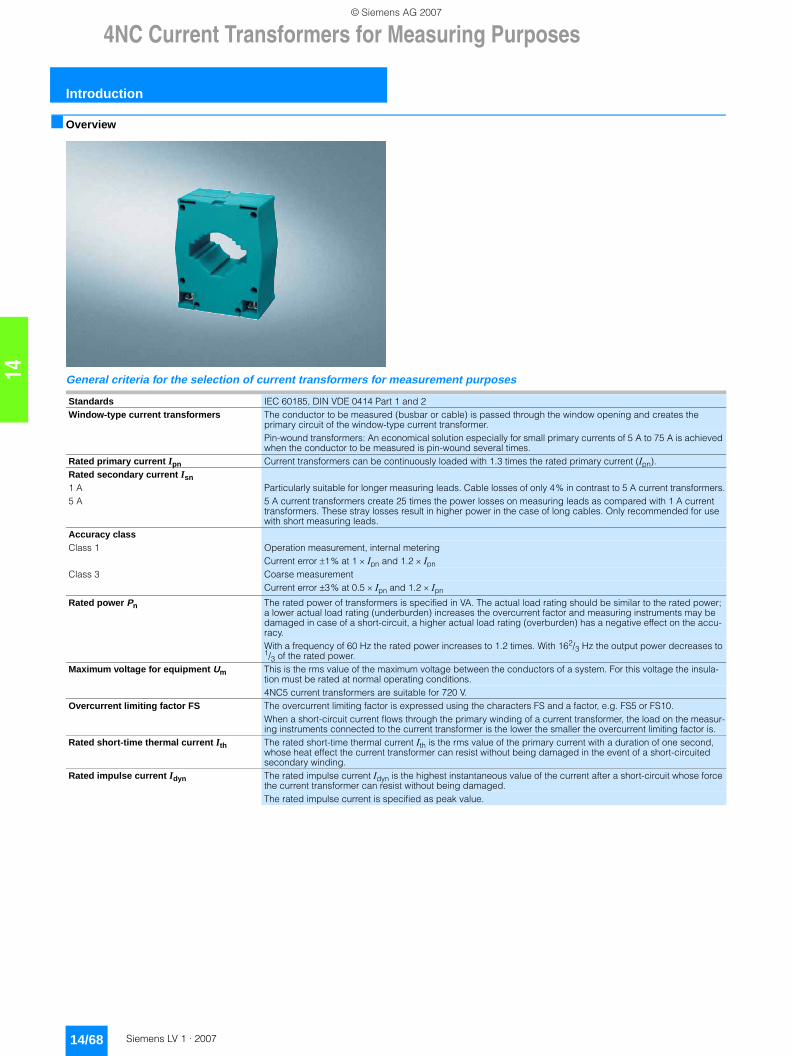
4NC Current Transformers for Measuring Purposes
Introduction
14/68 Siemens LV 1 · 2007
14
■ Overview
General criteria for the selection of current transformers for measurement purposes
Standards IEC 60185, DIN VDE 0414 Part 1 and 2Window-type current transformers The conductor to be measured (busbar or cable) is passed through the window opening and creates the
primary circuit of the window-type current transformer.Pin-wound transformers: An economical solution especially for small primary currents of 5 A to 75 A is achieved when the conductor to be measured is pin-wound several times.
Rated primary current Ipn Current transformers can be continuously loaded with 1.3 times the rated primary current (Ipn).Rated secondary current Isn1 A Particularly suitable for longer measuring leads. Cable losses of only 4% in contrast to 5 A current transformers.5 A 5 A current transformers create 25 times the power losses on measuring leads as compared with 1 A current
transformers. These stray losses result in higher power in the case of long cables. Only recommended for use with short measuring leads.
Accuracy classClass 1 Operation measurement, internal metering
Current error ±1% at 1 × Ipn and 1.2 × Ipn Class 3 Coarse measurement
Current error ±3% at 0.5 × Ipn and 1.2 × Ipn
Rated power Pn The rated power of transformers is specified in VA. The actual load rating should be similar to the rated power; a lower actual load rating (underburden) increases the overcurrent factor and measuring instruments may be damaged in case of a short-circuit, a higher actual load rating (overburden) has a negative effect on the accu-racy.With a frequency of 60 Hz the rated power increases to 1.2 times. With 162/3 Hz the output power decreases to 1/3 of the rated power.
Maximum voltage for equipment Um This is the rms value of the maximum voltage between the conductors of a system. For this voltage the insula-tion must be rated at normal operating conditions.4NC5 current transformers are suitable for 720 V.
Overcurrent limiting factor FS The overcurrent limiting factor is expressed using the characters FS and a factor, e.g. FS5 or FS10.When a short-circuit current flows through the primary winding of a current transformer, the load on the measur-ing instruments connected to the current transformer is the lower the smaller the overcurrent limiting factor is.
Rated short-time thermal current Ith The rated short-time thermal current Ith is the rms value of the primary current with a duration of one second, whose heat effect the current transformer can resist without being damaged in the event of a short-circuited secondary winding.
Rated impulse current Idyn The rated impulse current Idyn is the highest instantaneous value of the current after a short-circuit whose force the current transformer can resist without being damaged.The rated impulse current is specified as peak value.
LV1_14.book Seite 68 Freitag, 26. Januar 2007 11:23 11
© Siemens AG 2007
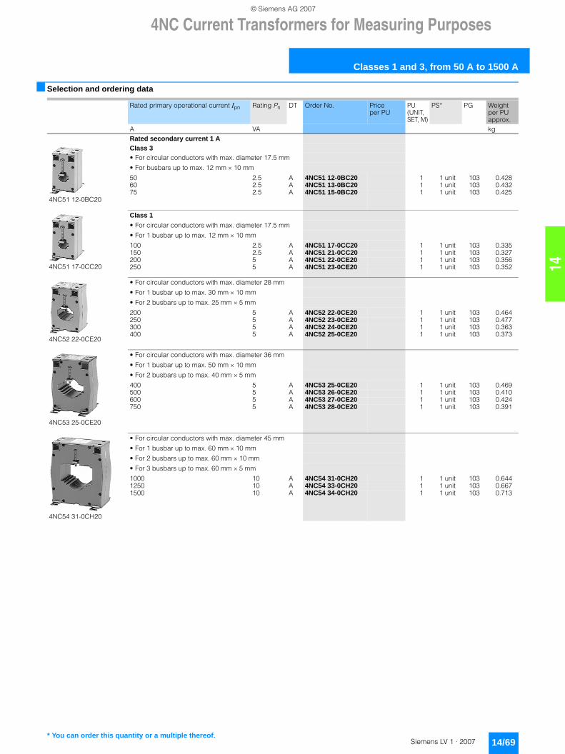
14
4NC Current Transformers for Measuring Purposes
Classes 1 and 3, from 50 A to 1500 A
14/69Siemens LV 1 · 2007
■ Selection and ordering data
Rated primary operational current Ipn Rating Pn DT Order No. Price per PU
PU (UNIT, SET, M)
PS* PG Weight per PU approx.
A VA kgRated secondary current 1 A
4NC51 12-0BC20
Class 3• For circular conductors with max. diameter 17.5 mm
• For busbars up to max. 12 mm × 10 mm
50 2.5 A 4NC51 12-0BC20 1 1 unit 103 0.42860 2.5 A 4NC51 13-0BC20 1 1 unit 103 0.43275 2.5 A 4NC51 15-0BC20 1 1 unit 103 0.425
4NC51 17-0CC20
Class 1
• For circular conductors with max. diameter 17.5 mm
• For 1 busbar up to max. 12 mm × 10 mm
100 2.5 A 4NC51 17-0CC20 1 1 unit 103 0.335150 2.5 A 4NC51 21-0CC20 1 1 unit 103 0.327200 5 A 4NC51 22-0CE20 1 1 unit 103 0.356250 5 A 4NC51 23-0CE20 1 1 unit 103 0.352
4NC52 22-0CE20
• For circular conductors with max. diameter 28 mm
• For 1 busbar up to max. 30 mm × 10 mm
• For 2 busbars up to max. 25 mm × 5 mm
200 5 A 4NC52 22-0CE20 1 1 unit 103 0.464250 5 A 4NC52 23-0CE20 1 1 unit 103 0.477300 5 A 4NC52 24-0CE20 1 1 unit 103 0.363400 5 A 4NC52 25-0CE20 1 1 unit 103 0.373
4NC53 25-0CE20
• For circular conductors with max. diameter 36 mm
• For 1 busbar up to max. 50 mm × 10 mm
• For 2 busbars up to max. 40 mm × 5 mm
400 5 A 4NC53 25-0CE20 1 1 unit 103 0.469500 5 A 4NC53 26-0CE20 1 1 unit 103 0.410600 5 A 4NC53 27-0CE20 1 1 unit 103 0.424750 5 A 4NC53 28-0CE20 1 1 unit 103 0.391
4NC54 31-0CH20
• For circular conductors with max. diameter 45 mm
• For 1 busbar up to max. 60 mm × 10 mm
• For 2 busbars up to max. 60 mm × 10 mm
• For 3 busbars up to max. 60 mm × 5 mm
1000 10 A 4NC54 31-0CH20 1 1 unit 103 0.6441250 10 A 4NC54 33-0CH20 1 1 unit 103 0.6671500 10 A 4NC54 34-0CH20 1 1 unit 103 0.713
* You can order this quantity or a multiple thereof.
LV1_14.book Seite 69 Freitag, 26. Januar 2007 11:23 11
© Siemens AG 2007
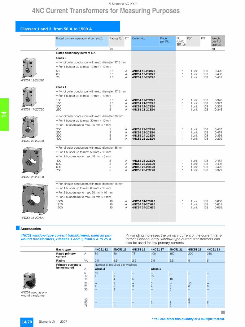
4NC Current Transformers for Measuring Purposes
Classes 1 and 3, from 50 A to 1500 A
14/70 Siemens LV 1 · 2007
14
■ Accessories
4NC51 window-type current transformers, used as pin-wound transformers, Classes 1 and 3, from 5 A to 75 A
Pin-winding increases the primary current of the current trans-former. Consequently, window-type current transformers can also be used for low primary currents.
Rated secondary current 5 A
4NC51 12-2BC20
Class 3
• For circular conductors with max. diameter 17.5 mm
• For 1 busbar up to max. 12 mm × 10 mm
50 2.5 A 4NC51 12-2BC20 1 1 unit 103 0.42660 2.5 A 4NC51 13-2BC20 1 1 unit 103 0.43075 2.5 A 4NC51 15-2BC20 1 1 unit 103 0.431
4NC51 17-2CC20
Class 1
• For circular conductors with max. diameter 17.5 mm
• For 1 busbar up to max. 12 mm × 10 mm
100 2.5 A 4NC51 17-2CC20 1 1 unit 103 0.340150 2.5 A 4NC51 21-2CC20 1 1 unit 103 0.327200 5 A 4NC51 22-2CE20 1 1 unit 103 0.339250 5 A 4NC51 23-2CE20 1 1 unit 103 0.345
4NC52 22-2CE20
• For circular conductors with max. diameter 28 mm
• For 1 busbar up to max. 30 mm × 10 mm
• For 2 busbars up to max. 25 mm × 5 mm
200 5 A 4NC52 22-2CE20 1 1 unit 103 0.467250 5 A 4NC52 23-2CE20 1 1 unit 103 0.474300 5 A 4NC52 24-2CE20 1 1 unit 103 0.356400 5 A 4NC52 25-2CE20 1 1 unit 103 0.379
4NC53 25-2CE20
• For circular conductors with max. diameter 36 mm
• For 1 busbar up to max. 50 mm × 10 mm
• For 2 busbars up to max. 40 mm × 5 mm
400 5 A 4NC53 25-2CE20 1 1 unit 103 0.452500 5 A 4NC53 26-2CE20 1 1 unit 103 0.406600 5 A 4NC53 27-2CE20 1 1 unit 103 0.425750 5 A 4NC53 28-2CE20 1 1 unit 103 0.379
4NC54 31-2CH20
• For circular conductors with max. diameter 45 mm
• For 1 busbar up to max. 60 mm × 10 mm
• For 2 busbars up to max. 60 mm × 10 mm
• For 3 busbars up to max. 60 mm × 5 mm
1000 10 A 4NC54 31-2CH20 1 1 unit 103 0.6601250 10 A 4NC54 33-2CH20 1 1 unit 103 0.6311500 10 A 4NC54 34-2CH20 1 1 unit 103 0.669
Rated primary operational current Ipn Rating Pn DT Order No. Price per PU
PU (UNIT, SET, M)
PS* PG Weight per PU approx.
A VA kg
Basic type 4NC51 12 4NC51 13 4NC51 15 4NC51 17 4NC51 21 4NC51 22 4NC51 23Rated primary current
A 50 60 75 100 150 200 250
Rating VA 2.5 2.5 2.5 2.5 2.5 5 5Primary current to be measured
Number of required pin windingsA Class 3 Class 1
4NC51 used as pin-wound transformer
5 10 -- -- -- -- -- --10 5 6 -- 10 -- -- --15 -- 4 5 -- 10 -- --
20 -- 3 -- 5 -- 10 --25 2 -- 3 4 6 8 830 -- 2 -- -- 5 -- --
40 -- -- -- -- -- 5 --50 -- -- -- 2 3 4 575 -- -- -- -- 2 -- --
* You can order this quantity or a multiple thereof.
LV1_14.book Seite 70 Freitag, 26. Januar 2007 11:23 11
© Siemens AG 2007