AG 2007 SITRANS F flowmeters SITRANS F Cliterature.puertoricosupplier.com/017/JD17241.pdf ·...
44
SITRANS F flowmeters SITRANS F C System information MASSFLO coriolis mass flowmeters 4/110 Siemens FI 01 · 2008 4 ■ Overview SITRANS F C MASSFLO coriolis mass flowmeters are designed for measurement of a variety of liquids and gases. The meter is a multi parameter device offering accurate measurement of mass flow, volume flow, density, temperature and fraction. ■ Benefits Greater flexibility • Wide product program • Uniform sensor interface enabling "plug & play" for all trans- mitters • Compact or remote installation using the same transmitters and sensors Easier to commission All MASSFLO coriolis flowmeters feature a SENSORPROM memory unit which stores sensor calibration data and transmitter settings for the lifetime of the product. At commissioning the flowmeter commences measurement without any initial programming. The factory settings matching the sensor size are stored in the SENSORPROM unit. Also customer specified settings are down- loaded to the unit. Easier to service • Comprehensive self diagnosis and service menu enhances trouble shooting and meter verification. • Transmitter replacement requires no programming. SENSORPROM automatically updates all settings after initial- ization. Room for growth USM II the Universal Signal Module with "plug & play" simplicity makes it easy to access and integrate the flowmeter with almost any system and bus-protocol and it ensures the flowmeter will be easy to upgrade to future communication/bus platforms. ■ Application Coriolis mass flowmeters are suitable for measuring liquids and gases. The measurement is independent of changes in process conditions/parameters such as temperature, density, pressure, viscosity, conductivity and flow profile. Due to this versatility the meter is easy to install. The coriolis flow- meter is recognized for its high accuracy in a wide turn down range. Transmitter Page Com- pact Remote Ex- Appr oval Sensor Page MASS 6000 IP67 Polyamide enclosure 4/116 No Yes No FC300 DN 4 4/135 No Yes No MASS 2100 DI 1.5 4/139 Yes Yes No MASS 2100 DI 3 ... 40 4/143 No Yes No MASS MC2 DN 50 ... 150 4/153 No Yes Yes MASS MC2-Ex DN 50 ... 150 4/153 MASS 6000 19” 4/120 No Yes No FC300 DN 4 4/135 No Yes No MASS 2100 DI 1.5 4/139 No Yes No MASS 2100 DI 3 ...40 4/143 No Yes No MASS MC2 DN 50 ... 150 4/153 No Yes Yes MASS MC2-Ex DN 50 ... 150 4/153 MASS 6000 Ex 19” 4/120 No Yes Yes FC300 DN 4 4/135 No Yes Yes MASS 2100-Ex DI 1.5 4/139 No Yes Yes MASS 2100-Ex DI 3 ... 40 4/143 MASS 6000 Ex-d Stainless steel enclosure 4/127 No Yes Yes FC300 DN 4 4/135 No Yes Yes MASS 2100-Ex DI 1.5 4/139 Yes Yes Yes MASS 2100-Ex DI 3 ... 40 4/143 No Yes No MASS MC2 DN 50 ... 150 4/153 The main applications of the coriolis flowmeter can be found in all industries, such as: Chemical & pharma Detergents, bulk chemicals, phar- maceuticals, acids, alkalis Food & beverage Dairy products, beer, wine, soft- drinks, plato/brix, fruit juices and pulps, bottling, CO 2 dosing, CIP- liquids Automotive Fuel injection nozzle & pump test- ing, filling of AC units, engine con- sumption, paint robots Oil & gas Filling of gas bottles, furnace con- trol, CNG-dispensers, Test separa- tors, LPG Water & waste water Dosing of chemicals for water treatment © Siemens AG 2007
Transcript of AG 2007 SITRANS F flowmeters SITRANS F Cliterature.puertoricosupplier.com/017/JD17241.pdf ·...

SITRANS F flowmetersSITRANS F CSystem informationMASSFLO coriolis mass flowmeters
4/110 Siemens FI 01 · 2008
4
Overview
SITRANS F C MASSFLO coriolis mass flowmeters are designed for measurement of a variety of liquids and gases. The meter is a multi parameter device offering accurate measurement of mass flow, volume flow, density, temperature and fraction.
Benefits
Greater flexibility• Wide product program• Uniform sensor interface enabling "plug & play" for all trans-
mitters• Compact or remote installation using the same transmitters
and sensors
Easier to commission
All MASSFLO coriolis flowmeters feature a SENSORPROM memory unit which stores sensor calibration data and transmitter settings for the lifetime of the product.
At commissioning the flowmeter commences measurement without any initial programming.
The factory settings matching the sensor size are stored in the SENSORPROM unit. Also customer specified settings are down-loaded to the unit.
Easier to service• Comprehensive self diagnosis and service menu enhances
trouble shooting and meter verification.• Transmitter replacement requires no programming.
SENSORPROM automatically updates all settings after initial-ization.
Room for growth
USM II the Universal Signal Module with "plug & play" simplicity makes it easy to access and integrate the flowmeter with almost any system and bus-protocol and it ensures the flowmeter will be easy to upgrade to future communication/bus platforms.
Application
Coriolis mass flowmeters are suitable for measuring liquids and gases. The measurement is independent of changes in process conditions/parameters such as temperature, density, pressure, viscosity, conductivity and flow profile.
Due to this versatility the meter is easy to install. The coriolis flow-meter is recognized for its high accuracy in a wide turn down range.
Transmitter Page Com-pact
Remote Ex-Approval
Sensor Page
MASS 6000 IP67 Polyamide enclosure
4/116 No Yes No FC300 DN 4 4/135
No Yes No MASS 2100 DI 1.5
4/139
Yes Yes No MASS 2100 DI 3 ... 40
4/143
No Yes No MASS MC2 DN 50 ... 150
4/153
No Yes Yes MASS MC2-Ex DN 50 ... 150
4/153
MASS 6000 19” 4/120 No Yes No FC300 DN 4 4/135
No Yes No MASS 2100 DI 1.5
4/139
No Yes No MASS 2100 DI 3 ...40
4/143
No Yes No MASS MC2 DN 50 ... 150
4/153
No Yes Yes MASS MC2-Ex DN 50 ... 150
4/153
MASS 6000 Ex 19”
4/120 No Yes Yes FC300 DN 4 4/135
No Yes Yes MASS 2100-Ex DI 1.5
4/139
No Yes Yes MASS 2100-Ex DI 3 ... 40
4/143
MASS 6000 Ex-d Stainless steel enclosure
4/127 No Yes Yes FC300 DN 4 4/135
No Yes Yes MASS 2100-Ex DI 1.5
4/139
Yes Yes Yes MASS 2100-Ex DI 3 ... 40
4/143
No Yes No MASS MC2 DN 50 ... 150
4/153
The main applications of the coriolis flowmeter can be found in all industries, such as:
Chemical & pharma Detergents, bulk chemicals, phar-maceuticals, acids, alkalis
Food & beverage Dairy products, beer, wine, soft-drinks, plato/brix, fruit juices and pulps, bottling, CO2 dosing, CIP-liquids
Automotive Fuel injection nozzle & pump test-ing, filling of AC units, engine con-sumption, paint robots
Oil & gas Filling of gas bottles, furnace con-trol, CNG-dispensers, Test separa-tors, LPG
Water & waste water Dosing of chemicals for water treatment
© Siemens AG 2007

SITRANS F flowmetersSITRANS F C
System informationMASSFLO coriolis mass flowmeters
4/111Siemens FI 01 · 2008
4
Please see Product selectorwww.pia-selector.com/its_main_en.aspon the Internet, since some con-strains might be related to some of the features
MASS 2100DI 1.5
MASS 2100DI 3 to 40
FC300DN 4
MC2 DN 50 to 150
MASS 6000IP67
MASS 600019“
MASS 6000Ex-d
SIFLOWFC070
Design
Compact
Remote
Transmitter enclosurePolyamid, IP67/NEMA4X
Noryl (SIMATIC S7-300), IP20/NEMA 2
Stainless steel IP67/NEMA4X
19" rack IP20/NEMA2 aluminium
Back of panel IP20/NEMA2 aluminium
Wall mounting IP66/NEMA4 ABS plastic
Front of panel IP66/NEMA4 ABS plastic
Communication HART
PROFIBUS PA
PROFIBUS DP
MODBUS RTU / RS 485
MODBUS RTU / RS 232
Supply voltage24 V DC
24 V AC/DC
115/230 V AC
Pipe sizeDI 1.5
DI 3
DN 4
DI 6
DI 15
DN 20 2)
DI 25
DN 25 2)
DI 40
DN 50
DN 65
DN 80
DN 100
DN 150
Process connection norms and pressure
Pipe thread
NPT ANSI/ASME B.20.1; PN 100
ISO 228/1; PN 100
Flange
EN 1092-1 PN 40
EN 1092-1 PN 100 1)
ANSI B16.5 Class 150
ANSI B16.5 Class 300
ANSI B16.5 Class 600 1)
= available1) Not available for DN 100 and DN 150 sensors2) For Hygienic only
© Siemens AG 2007

SITRANS F flowmetersSITRANS F CSystem informationMASSFLO coriolis mass flowmeters
4/112 Siemens FI 01 · 2008
4
Dairy
DIN 11851 PN 25
DIN 11851 PN 40
Clamp ISO 2852 PN 16
ISO 2853 PN 16
DIN 32676 Tri-Clamp PN 10/PN 16
Others on request
Pipe material
Stainless steel 1.4435 (316L)
Stainless steel 1.4571 (316 Ti)
Hastelloy C - 22
Hastelloy C - 4
With heating jacket
Internal U - tube
Pressure rating
PN 10
PN 16
PN 25
PN 40
PN 100 1)
High pressure version2)
Accuracy
Flow error ≤ 0.1% of rate
Flow error ≤ 0.15% of rate
Density error ≤ 0.001 g/cm3
Density error ≤ 0.0015 g/cm3
3)
Density error ≤ 0.0005 g/cm3
Cable glands
PG 13.5
½“ NPT
M20
Approvals
Harzardous areas
ATEX Zone 0
ATEX Zone 1
ATEX Zone 2
UL Class 1 Division 1 4)
4)
4)
UL Class 1 Division 2 4)
4)
4)
5)
CSA/FM Class 1 Division 2 4)
4)
4)
5)
Type approvals
GOSS/Gost ( Russia)
CRN
= available1) Not available for DN 100 and DN 150 sensors2) Please see technical specifications3) DI 3 and DI 64) Sensor pressure max. 100 bar (1450 psi)5) Only IP66 version approved
Please see Product selectorwww.pia-selector.com/its_main_en.aspon the Internet, since some con-strains might be related to some of the features
MASS 2100DI 1.5
MASS 2100DI 3 to 40
FC300DN 4
MC2 DN 50 to 150
MASS 6000IP67
MASS 600019“
MASS 6000Ex-d
SIFLOWFC070
© Siemens AG 2007
SITRANS F flowmetersSITRANS F C
System informationMASSFLO coriolis mass flowmeters
4/113Siemens FI 01 · 2008
4
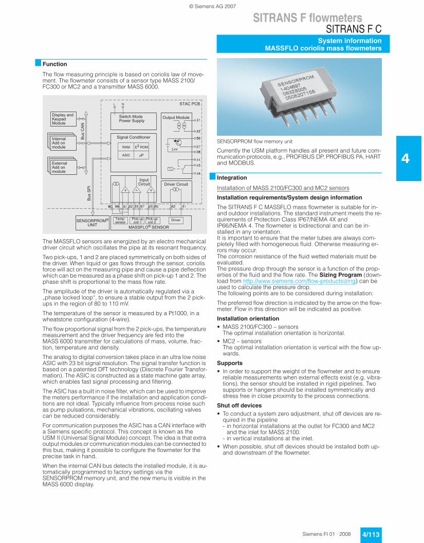
Function
The flow measuring principle is based on coriolis law of move-ment. The flowmeter consists of a sensor type MASS 2100/ FC300 or MC2 and a transmitter MASS 6000.
The MASSFLO sensors are energized by an electro mechanical driver circuit which oscillates the pipe at its resonant frequency.
Two pick-ups, 1 and 2 are placed symmetrically on both sides of the driver. When liquid or gas flows through the sensor, coriolis force will act on the measuring pipe and cause a pipe deflection which can be measured as a phase shift on pick-up 1 and 2. The phase shift is proportional to the mass flow rate.
The amplitude of the driver is automatically regulated via a „phase locked loop“, to ensure a stable output from the 2 pick-ups in the region of 80 to 110 mV.
The temperature of the sensor is measured by a Pt1000, in a wheatstone configuration (4-wire).
The flow proportional signal from the 2 pick-ups, the temperature measurement and the driver frequency are fed into the MASS 6000 transmitter for calculations of mass, volume, frac-tion, temperature and density.
The analog to digital conversion takes place in an ultra low noise ASIC with 23 bit signal resolution. The signal transfer function is based on a patented DFT technology (Discrete Fourier Transfor-mation). The ASIC is constructed as a state machine gate array, which enables fast signal processing and filtering.
The ASIC has a built in noise filter, which can be used to improve the meters performance if the installation and application condi-tions are not ideal. Typically influence from process noise such as pump pulsations, mechanical vibrations, oscillating valves can be reduced considerably.
For communication purposes the ASIC has a CAN interface with a Siemens specific protocol. This concept is known as the USM II (Universal Signal Module) concept. The idea is that extra output modules or communication modules can be connected to this bus, making it possible to configure the flowmeter for the precise task in hand.
When the internal CAN bus detects the installed module, it is au-tomatically programmed to factory settings via the SENSORPROM memory unit, and the new menu is visible in the MASS 6000 display.
SENSORPROM flow memory unit
Currently the USM platform handles all present and future com-munication protocols, e.g., PROFIBUS DP, PROFIBUS PA, HART and MODBUS.
Integration
Installation of MASS 2100/FC300 and MC2 sensors
Installation requirements/System design information
The SITRANS F C MASSFLO mass flowmeter is suitable for in- and outdoor installations. The standard instrument meets the re-quirements of Protection Class IP67/NEMA 4X and IP66/NEMA 4. The flowmeter is bidirectional and can be in-stalled in any orientation. It is important to ensure that the meter tubes are always com-pletely filled with homogeneous fluid. Otherwise measuring er-rors may occur. The corrosion resistance of the fluid wetted materials must be evaluated.The pressure drop through the sensor is a function of the prop-erties of the fluid and the flow rate. The Sizing Program (down-load from http://www.siemens.com/flow-productsizing) can be used to calculate the pressure drop.The following points are to be considered during installation:
The preferred flow direction is indicated by the arrow on the flow-meter. Flow in this direction will be indicated as positive.
Installation orientation • MASS 2100/FC300 – sensors
The optimal installation orientation is horizontal.• MC2 – sensors
The optimal installation orientation is vertical with the flow up-wards.
Supports • In order to support the weight of the flowmeter and to ensure
reliable measurements when external effects exist (e.g. vibra-tions), the sensor should be installed in rigid pipelines. Two supports or hangers should be installed symmetrically and stress free in close proximity to the process connections.
Shut off devices • To conduct a system zero adjustment, shut off devices are re-
quired in the pipeline - in horizontal installations at the outlet for FC300 and MC2
and the inlet for MASS 2100.- in vertical installations at the inlet.
• When possible, shut off devices should be installed both up- and downstream of the flowmeter.
© Siemens AG 2007

SITRANS F flowmetersSITRANS F CSystem informationMASSFLO coriolis mass flowmeters
4/114 Siemens FI 01 · 2008
4
Installation: straight run requirements• The mass flowmeter does not require any flow conditioning in-
let straight sections. Care should be exercised to ensure that any valves, gates, sight glasses etc. do not cavitate and are not set into vibration by the flowmeter.
System design information • The presence of gas bubbles in the fluid may result in errone-
ous measurements, particularly in the density measurement. Therefore the flowmeter should not be installed at the highest point in the system. Advantageous are installations in low pipeline sections, at the bottom of a U-section in the pipeline.
• Long drop lines downstream from the flowmeter should be avoided to prevent the meter tube from draining.
• The flowmeter should not come into contact with any other ob-jects. Avoid attachments to the housing.
• When the cross-section of the connecting pipeline is larger than the sensor size, suitable standard reducers may be in-stalled.
• If strong vibrations exist in the pipeline, they should be damped using elastic pipeline elements. The damping de-vices must be installed outside the supported flowmeter sec-tion and outside the section between the shut off devices. The direct connection of flexible elements to the sensor should be avoided.
• Make sure that any dissolved gases, which are present in many liquids, do not outgas. The back pressure at the outlet should be at least 0.1 to 0.2 bar (0.5 to 3 psi).
• Assure that operation below the vapor pressure cannot occur when a vacuum exists in the meter tube or for fluids which boil readily.
• The sensor should not be installed in the vicinity of strong elec-tromagnetic fields, e.g. near motors, pumps, transformers etc.
• When operating more than one meter in one or multiple inter-connected pipelines, the sensor should be spaced distant from each other or the pipelines should be decoupled to pre-vent cross talk.
Zero adjustment • In order to adjust the zero under operating conditions it must
be possible to reduce the flow rate to „ZERO“ while the meter tube is completely filled. A bypass line is optimal when the process cannot be shut down. It is important for accurate measurements that during the zero adjustment there are no gas bubbles in the flowmeter. It is also important that the pres-sure and temperature in the meter tube be the same as that which exists during operation.
Technical specifications
Flowmeter uncertainty/specifications
To ensure continuous accurate measurement, flowmeters must be calibrated. The calibration is conducted at SIEMENS flow fa-cilities accredited according to ISO/IEC 17025 by DANAK or UKAS.
The accreditation bodies DANAK and UKAS have signed the ILAC MRA agreement (International Laboratory Accreditation Corporation - Mutual Recognition Arrangement). Therefore the accreditation ensures international traceability and recognition of the test results in 39 countries world wide, including the US (NIST traceability).
A calibration certificate is shipped with every sensor and cali-bration data are stored in the SENSORPROM memory unit.
MASS 2100 sensors and MASS 6000 transmitters
• For flow > 5% of the sensors max. flow rate, the error can be read directly from the curve.
• For flow < 5% of the sensors max. flow rate, use the formula to calculate the error.
• The error curve is plotted from the formula:
E = Error [%]Z = Zero point error [kg/h]qm = Mass flow [kg/h]
5% 50% 100%
DI 1.5 (1/16”) 1 kg/h 32.5 kg/h 65 kg/h (140 lb/h)
DI 3 (1/8”) 12 kg/h 125 kg/h 250 kg/h (550 lb/h)
DN 4 (1/6") 17.5 kg/h 175 kg/h 350 kg/h (770 lb/h)
DI 6 (¼”) 50 kg/h 500 kg/h 1000 kg/h (2200 lb/h)
DI 15 (½”) 280 kg/h 2800 kg/h 5600 kg/h (12345 lb/h)
DI 25 (1”) 1250 kg/h 12500 kg/h 25000 kg/h (55100 lb/h)
DI 40 (1½”) 2600 kg/h 26000 kg/h 52000 kg/h (114600 lb/h)
100%75%
-0.1 0.10.5
1.0
-0.5
-1.05% 25% 50%
Actual mass flow rate
Error in % of actual mass flow rate with 95% confidence (probability)
FSO (sensors max. flow rate)
Sensor type FC300 MASS 2100
Sensor size DN 4 (1/6") DI 1.5 (1/16”) DI 3 (1/8”) DI 6 (¼“) DI 15 (½“) DI 25 (1”) DI 40 (1½“)
Number of measuring pipes 1 1 1 1 1 1 1
Mass flow
Linearity error % of rate 0.10 0.10 0.10 0.10 0.10 0.10 0.10
Repeatability error % of rate 0.05 0.05 0.05 0.05 0.05 0.05 0.05
Max. zero point error
[kg/h] 0.010 0.001 0.010 0.050 0.200 1.500 6.000
Density
Density error [g/cm3] 0.0015 0.001 0.0015 0.0015 0.0005 0.0005 0.0005
Repeatability error [g/cm3] 0.0002 0.0002 0.0002 0.0002 0.0001 0.0001 0.0001
Range [g/cm3] 0 ... 2.9 0 ... 2.9 0 ... 2.9 0 ... 2.9 0 ... 2.9 0 ... 2.9 0 ... 2.9
Modification 01/2008
© Siemens AG 2008

SITRANS F flowmetersSITRANS F C
System informationMASSFLO coriolis mass flowmeters
4/115Siemens FI 01 · 2008
4
1) Extended density calibration required.
Flowmeter uncertainty/specifications
MASS MC2 sensors and MASS 6000 transmitters
E = Error [%]Z = Zero point error [kg/h]qm = Mass flow [kg/h]
Qmax. at 2 bar pressure loss at 1 g/cm3
Temperature
Error [°C (°F)] 0.5 (1) 0.5 (1) 0.5 (1) 0.5 (1) 0.5 (1) 0.5 (1) 0.5 (1)
Brix
Error [°Brix] 0.3 0.2 0.3 0.3 0.1 0.1 0.1
Sensor type FC300 MASS 2100
Sensor type MASS MC2
Sensor size DN 50 (2”) DN 65 (2½”) DN 80 (3”) DN 100 (4”) DN 150 (6”)
Sensor size (for hygienic only) DN 20 (¾“), DN 25 (1“), DN 40 (1½“), DN 50 (2“),
DN 65 (2½”) DN 80 (3”)
Number of measuring pipes 2 2 2 2 2
Mass flow:
Linearity error % of rate 0.15 0.15 0.15 0.15 0.15
Repeatability error % of rate 0.1 0.1 0.1 0.1 0.1
Max. zero point error
[kg/h] 5.52 11.34 14.76 24.96 66.00
Density
Density error (Standard) [g/cm3] 0.005 0.005 0.005 0.005 0.005
(Extended) [g/cm3] 0.001 0.001 0.001 0.001 Not available
Range [g/cm3] 0 ... 3.5 0 ... 3.5 0 ... 3.5 0 ... 3.5 0 ... 3.5
Repeatability error [g/cm3] 0.0001 0.0001 0.0001 0.0001 0.0001
Temperature
Error [°C (°F)] 1.0 (1.8) 1.0 (1.8) 1.0 (1.8) 1.0 (1.8) 1.0 (1.8)
Brix 1)
Error [°Brix] 0.2 0.2 0.2 0.2 Not available
5% 50% 100%
DN 20 (¾”) 6000 kg/h (13200 lb/h)
DN 25 (1”) 9600 kg/h (21120 lb/h)
DN 40 (1½”) 28500 kg/h (62700 lb/h)
DN 50 (2”) 2130 kg/h 21300 kg/h 42600 kg/h (93900 lb/h)
DN 65 (2½”) 4350 kg/h 43500 kg/h 87000 kg/h (191800 lb/h)
DN 80 (3”) 5670 kg/h 56700 kg/h 113400 kg/h (250000 lb/h)
DN 100 (4”) 9600 kg/h 96000 kg/h 192000 kg/h (423300 lb/h)
DN 150 (6”) 25500 kg/h 255000 kg/h 510000 kg/h (1124000 lb/h)
100%75%
-0.15 0.150.5
1.0
-0.5
-1.05% 25% 50%
Actual mass flow rate
Error in % of actual mass flow rate with 95% confidence (probability)
FSO (sensors max. flow rate)
Reference conditions (ISO 9104 and DIN/EN 29104)
Flow conditions Fully developed flow profile
Temperature, medium 20 °C ± 2 K (68 °C ± 3.6 °F)
Temperature, ambient 20 °C ± 2 K (68 °C ± 3.6 °F)
Liquid pressure 2 ± 1 bar
Density 0.997 g/cm3
Brix 40 °Brix
Supply voltage Un ±1%
Warming-up time 30 min.
Cable length 5 m between transmitter and sen-sor
Additions in the event of deviations from reference conditions
Current output As pulse output (± 0.1% of actual flow +0.05% FSO)
Effect of ambient temperature • Display/frequency/pulse output: < ± 0.003% / K act.
• Current output: < ± 0.005% / K act.
Effect of supply voltage < 0.005% of measuring value on 1% alteration
Modification 01/2008
© Siemens AG 2008

SITRANS F flowmetersSITRANS F C
MASSFLO MASS 6000 IP67 compact/remote
4/116 Siemens FI 01 · 2008
4
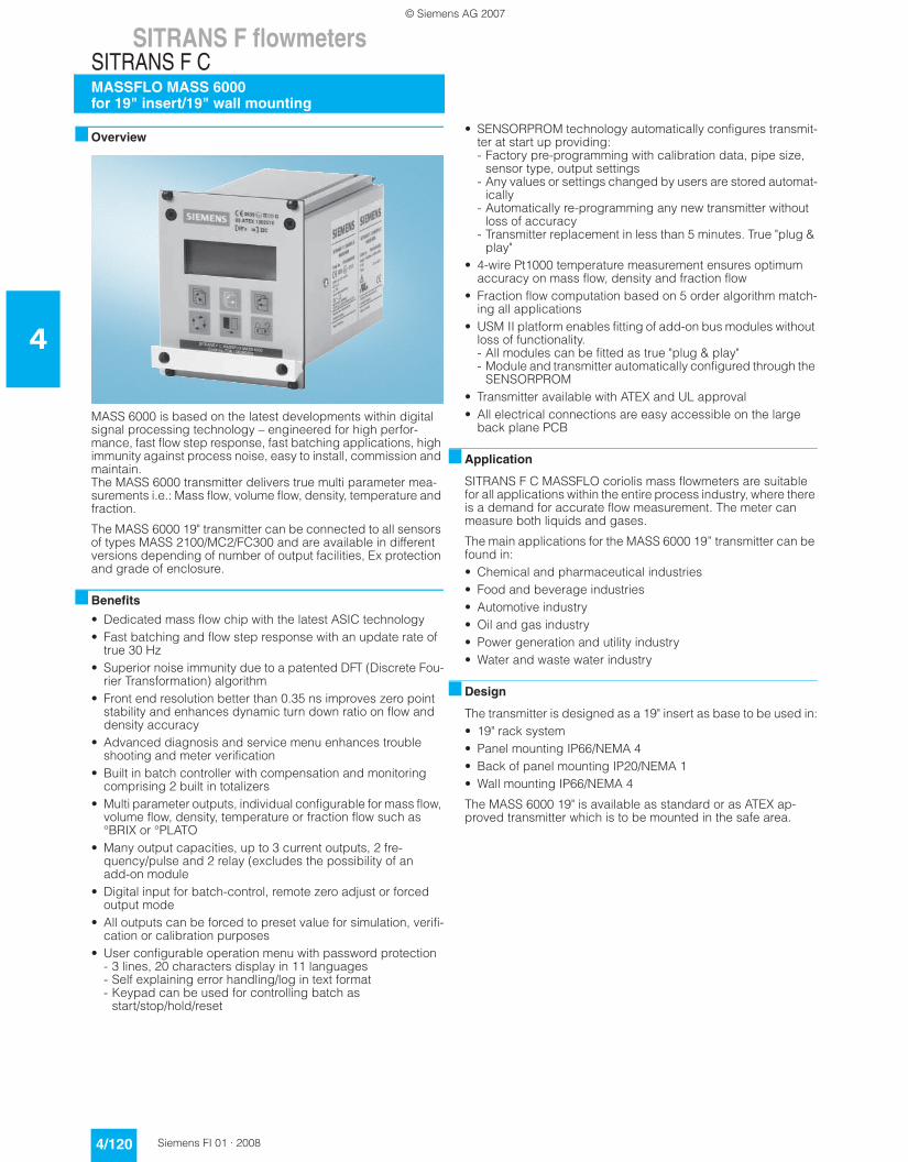
Overview
MASS 6000 is based on the latest developments within digital signal processing technology – engineered for high perfor-mance, fast flow step response, fast batching applications, high immunity against process noise, easy to install, commission and maintain.
The MASS 6000 transmitter delivers true multiparameter mea-surements i.e. mass flow, volume flow, density, temperature and fraction.
The MASS 6000 IP67 transmitter can be compact mounted on all sensors of type MASS 2100 DI 3 to DI 40, and can be used in remote version for all types of MASS 2100/MC2 and FC300 sen-sors.
Benefits
• Dedicated mass flow chip with the latest ASIC technology• Fast batching and flow step response with an update rate of
true 30 Hz• Superior noise immunity due to a patented DFT (Discrete Fou-
rier Transformation) algorithm• Front end resolution better than 0.35 ns improves zero point
stability and enhances dynamic turn down ratio on flow and density accuracy
• Advanced diagnosis and service menu enhances trouble shooting and meter verification
• Built-in batch controller with compensation and monitoring comprising 2 built in totalizers
• Multi parameter outputs, individual configurable for mass flow, volume flow, density, temperature or fraction flow such as °BRIX or °PLATO
• Digital input for batch-control, remote zero adjust or forced output mode
• All outputs can be forced to preset value for simulation, verifi-cation or calibration purposes
• User configurable operation menu with password protection - 3 lines, 20 characters display in 11 languages- Self explaining error handling/log in text format- Keypad can be used for controlling batch as
start/stop/hold/reset• SENSORPROM technology automatically configures transmit-
ter at start up providing: - Factory pre-programming with calibration data, pipe size,
sensor type, output settings- Any values or settings changed by users are stored
automatically- Automatically re-programming any new transmitter without
loss of accuracy- Transmitter replacement in less than 5 minutes. True "plug &
play"• 4-wire Pt1000 temperature measurement ensures optimum
accuracy on mass flow, density and fraction flow
• Fraction flow computation based on 5 order algorithm match-ing all applications
• USM II platform enables fitting of add-on bus modules without loss of functionality. - All modules can be fitted as true "plug & play"- Module and transmitter are automatically configured through
the SENSORPROM• Installation of the transmitter to the sensor is simple "plug &
play" via the sensor pedestal
Application
SITRANS F C MASSFLO mass flowmeters are suitable for all ap-plications within the entire process industry, where there is a de-mand for accurate flow measurement. The meter is capable of measuring both liquid and gas flow.
The main applications for the MASS 6000 IP67 transmitter can be found in:• Food and beverage industries• Pharmaceutical industries• Automotive industry• Oil and gas industry• Power generation and utility industry• Water and waste water industry
Design
The transmitter is designed in an IP67/NEMA 4X compact polyamide enclosure which can be compact mounted on the MASS 2100 sensor range DI 3 to DI 40 (1/8" to 1½") and remote mounted for the entire sensor series.
The MASS 6000 IP67 is available as standard with 1 current-, 1 frequency/pulse- and 1 relay output and can be fitted with add-on modules for bus communication.
Function
The following functions are available:• Mass flow rate, volume flow rate, density, temperature, fraction
flow• 1 current output, 1 frequency/pulse output, 1 relay output,
1 digital input• All outputs can be individually configured with mass, volume,
density etc.• 2 built in totalizes which can count positive, negative or net• Low flow cut-off• Density cut-off or empty pipe cut-off, adjustable• Flow direction adjustable• Error system consisting of error-log, error pending menu• Display of operating time• Uni/bidirectional flow measurement• Limit switches with 1 or 2 limits, programmable for flow, den-
sity or temperature• Noise filter setting for optimization of measurement perfor-
mance under non ideal application conditions• Full batch controller• Automatic zero adjustment menu, with zero point evaluation
feed back• Full service menu for effective and straight forward application
and meter trouble shooting
© Siemens AG 2007

SITRANS F flowmetersSITRANS F C
MASSFLO MASS 6000 IP67 compact/remote
4/117Siemens FI 01 · 2008
4
Technical specifications
Measurement of Mass flow [kg/s (lbs/min)], volume flow [l/s (gpm)], fraction [%], °Brix, density [kg/m3, (lbs/ft3)], temperature [°C (°F)]
Current output
Current 0 ... 20 mA or 4 ... 20 mA
Load < 800 Ω
Time constant 0 ... 30 s adjustable
Digital output
Frequency 0 ... 10 kHz, 50% duty cycle
Time constant 0 ... 30 s adjustable
Active 24 V DC, 30 mA, 1 KΩ ≤ Rload ≤ 10 KΩ, short-circuit-protected
Passive 3 ... 30 V DC, max. 110 mA, 1 KΩ ≤ Rload ≤ 10 KΩ
Relay
Type Change-over relay
Load 42 V/2 A peak
Functions Error level, error number, limit, flow direction
Digital input 11 ... 30 V DC (Ri = 13.6 KΩ)
Functionality Start/hold/continue batch, zero point adjust, reset totalizer 1/2, force output, freeze output
Galvanic isolation All inputs and outputs are galvan-ically isolated, isolation voltage 500 V
Cut-off
Low-flow 0 ... 9.9% of maximum flow
Limit function Mass flow, volume flow, fraction, density, sensor temperature
Totalizer Two eight-digit counters for for-ward, net or reverse flow
Display • Background illumination with al-phanumerical text, 3 × 20 char-acters to indicate flow rate, totalized values, settings and faults. Time constant as current output 1
• Reverse flow indicated by nega-tive sign
Zero point adjustment Manual via keypad or remote via digital input
Ambient temperature
Operation -20 ... +50 °C (-4 ... +122 °F), max. rel. humidity 80% to 31 °C (87.8 °F) decreasing to 50% at 40 °C (104 °F) according to UL 3101
Storage -40 ... +70 °C (-40 ... +158 °F) (Humidity max. 95%)
Communication Add-on modules: HART, PROFIBUS PA & DP, MODBUS RTU RS 485
Enclosure
Material Fibre glass-reinforced polyamide
Rating IP67/NEMA 4X to IEC 529 and DIN 40050 (1 m w.g. for 30 min.)
Mechanical load 18 ... 1000 Hz random, 3.17G rms, in all directions, to IEC 68-2-36
Supply voltage
24 V version
• Supply 24 V DC/AC, 50 ... 60 Hz
• Fluctuation 18 ... 30 V DC20 ... 30 V AC
• Power consumption 10 W
230 V version
• Supply 115/230 V AC, 50 ... 60 Hz
• Fluctuation +10% ... -10%
• Power consumption 26 VA
Fuse
• 230 V version T400 mA, T 250 V (IEC 127) - Not to be changed by user
• 24 V version T1 A, T 250 V (IEC 127) - Not to be changed by user
EMC performance
Emission EN 50081-1 (Light industry)
Immunity EN 50082-2 (Industry)
NAMUR Within the value limits according to "Allgemeine Anforderung" with error criteria A in accordance with NE 21
Evironment
Environmental conditions acc. to UL 3101:
• Altitude up to 2000 m• POLLUTION DEGREE 2
Maintenance The flowmeter has a built-in error log/pending menu which should be inspected on a regular basis
Cable glands Two types of cable gland are available in polyamide in the fol-lowing dimensions: M20 or ½“ NPT
© Siemens AG 2007

SITRANS F flowmetersSITRANS F C
MASSFLO MASS 6000 IP67 compact/remote
4/118 Siemens FI 01 · 2008
4
Please also see www.siemens.com/SITRANSForderingfor practical examples of ordering
Accessories
Cable glands
Spare parts for compact or remote IP67 version
Add-on module
Selection and Ordering data Order-No.
SITRANS F C MASSFLO MASS 6000 transmitterTransmitter for wall mounting with wall mounting bracket, fibreglass reinforced polyamide (1 current output, 1 frq./pulse output and 1 relay output)
F) 7ME4110-
7A A7 0 - 77A7
VersionRemote IP67/NEMA 4X enclosure 2
Supply voltage
115/230 V AC, 50 ... 60 Hz 124 V AC/DC 2
Display/Keypad
with display 1
Serial communication
No communication AHART BPROFIBUS PA Profile 3 F
PROFIBUS DP Profile 3 GMODBUS RTU RS 485 E
Cable glands
M20 1½“ NPT 2
Description Order No.F) Symbol
Cable glands, screwed entries type in polyamide (100 °C (212 °F)) black, 2-off
• M20 A5E00822490
• ½“ NPT A5E01163775
Description Version Power supply Order No.F) Symbol
MASS 6000 transmitterIP67/NEMA 4X, fibreglass reinforced polyamide
1 current output1 frq./pulse output1 relay output
115/230 V AC, 50/60 Hz 7ME4110-1AA10-1AA0
24 V AC/DC 7ME4110-1AA20-1AA0
Description Order No.F) Symbol
Wall mounting unit for IP67/NEMA 4X version with wall bracket and with
• 4 x M20 cable glands FDK-085U1018
• 4 x ½“ NPT cable glands A5E01164211
Connection board/PCB Supply voltage: 115/230 V / 24 V AC/DC
FDK-083H4260
Terminal box kit with
• M20 cable glands A5E00832338
• ½“ NPT cable glands A5E00832342
With this kit you are able to mount the MASS 6000 IP67/NEMA 4X transmitter on the MASS 2100 sensor and make it to a compact system. (The kit consisting of a terminal box in polyamide, cable and connector between PCB and sensor piedestal, PCB, seal and screws (4 pcs.) for mount-ing on sensor)
Terminal box with
• M20 cable glands FDK-085U1050
• ½“ NPT cable glands A5E01164206
Terminal box – in polyamide exclusive lid
FDK-085U1002
Terminal box – lid in polya-mide
FDK-085U1003
Description Order No.F) Symbol
HART FDK-085U0226
PROFIBUS PA Profile 3 FDK-085U0236
PROFIBUS DP Profile 3 FDK-085U0237
MODBUS RTU RS 485 FDK-085U0234
Description Order No.F) Symbol
F) All products on this page subject to export regulations AL: 9I999, ECCN: N.
© Siemens AG 2007

SITRANS F flowmetersSITRANS F C
MASSFLO MASS 6000 IP67 compact/remote
4/119Siemens FI 01 · 2008
4
Dimensional drawings
Compact
MASS 2100
Transmitter wall mounted
Schematics
Electrical connection
Grounding
PE must be connected due to safety class 1 power supply.
Mechanical counters
When mounting a mechanical counter to terminals 57 and 58 (active output), a 1000 µF capacitor must be connected to the terminals 56 and 58. Capacitor + is connected to terminal 56 and capacitor - to terminal 58.
Output cables
If long cables are used in a noisy environment, it is recommend that shielded cables be used.
Sensor size [DN (inch)]
L3[mm (inch)]
H5[mm (inch)]
H6[mm (inch)]
H5 + H6[mm (inch)]
3 (1/8) 75 (2.95) 82 (3.23) 246 (9.69) 328 (12.91)
6 (¼) 62 (2.44) 72 (2.83) 256 (10.08) 328 (12.91)
15 (½) 75 (2.95) 87 (3.43) 267 (10.51) 353 (13.90)
25 (1) 75 (2.95) 173 (6.81) 271 (10.67) 443 (17.44)
40 (1½) 75 (2.95) 227 (8.94) 271 (10.67) 497 (19.57)
Digital input 11 ... 30 V DC
Counter (plc)
Active outputMax. 30 mA
Passive outputMax. 30 V/110 mA
Relay shown in de-energised conditionRelay42 V AC/2A42 V DC/2A
0/4 ... 20 mALoad 800 Ω
18 ... 30 V DC20 ... 30 V AC
Relay
Currentoutput
Transmitter
115/230 V AC
PE
© Siemens AG 2007
SITRANS F flowmetersSITRANS F CMASSFLO MASS 6000for 19" insert/19" wall mounting
4/120 Siemens FI 01 · 2008
4
Overview
MASS 6000 is based on the latest developments within digital signal processing technology – engineered for high perfor-mance, fast flow step response, fast batching applications, high immunity against process noise, easy to install, commission and maintain.The MASS 6000 transmitter delivers true multi parameter mea-surements i.e.: Mass flow, volume flow, density, temperature and fraction.
The MASS 6000 19" transmitter can be connected to all sensors of types MASS 2100/MC2/FC300 and are available in different versions depending of number of output facilities, Ex protection and grade of enclosure.
Benefits
• Dedicated mass flow chip with the latest ASIC technology• Fast batching and flow step response with an update rate of
true 30 Hz• Superior noise immunity due to a patented DFT (Discrete Fou-
rier Transformation) algorithm• Front end resolution better than 0.35 ns improves zero point
stability and enhances dynamic turn down ratio on flow and density accuracy
• Advanced diagnosis and service menu enhances trouble shooting and meter verification
• Built in batch controller with compensation and monitoring comprising 2 built in totalizers
• Multi parameter outputs, individual configurable for mass flow, volume flow, density, temperature or fraction flow such as °BRIX or °PLATO
• Many output capacities, up to 3 current outputs, 2 fre-quency/pulse and 2 relay (excludes the possibility of an add-on module
• Digital input for batch-control, remote zero adjust or forced output mode
• All outputs can be forced to preset value for simulation, verifi-cation or calibration purposes
• User configurable operation menu with password protection - 3 lines, 20 characters display in 11 languages- Self explaining error handling/log in text format- Keypad can be used for controlling batch as
start/stop/hold/reset
• SENSORPROM technology automatically configures transmit-ter at start up providing: - Factory pre-programming with calibration data, pipe size,
sensor type, output settings- Any values or settings changed by users are stored automat-
ically- Automatically re-programming any new transmitter without
loss of accuracy- Transmitter replacement in less than 5 minutes. True "plug &
play"• 4-wire Pt1000 temperature measurement ensures optimum
accuracy on mass flow, density and fraction flow• Fraction flow computation based on 5 order algorithm match-
ing all applications• USM II platform enables fitting of add-on bus modules without
loss of functionality. - All modules can be fitted as true "plug & play"- Module and transmitter automatically configured through the
SENSORPROM• Transmitter available with ATEX and UL approval• All electrical connections are easy accessible on the large
back plane PCB
Application
SITRANS F C MASSFLO coriolis mass flowmeters are suitable for all applications within the entire process industry, where there is a demand for accurate flow measurement. The meter can measure both liquids and gases.
The main applications for the MASS 6000 19” transmitter can be found in:• Chemical and pharmaceutical industries• Food and beverage industries• Automotive industry• Oil and gas industry• Power generation and utility industry• Water and waste water industry
Design
The transmitter is designed as a 19" insert as base to be used in:• 19" rack system• Panel mounting IP66/NEMA 4• Back of panel mounting IP20/NEMA 1• Wall mounting IP66/NEMA 4
The MASS 6000 19" is available as standard or as ATEX ap-proved transmitter which is to be mounted in the safe area.
© Siemens AG 2007

SITRANS F flowmetersSITRANS F C
MASSFLO MASS 6000for 19" insert/19" wall mounting
4/121Siemens FI 01 · 2008
4
Function
The following functions are available:• Mass flow rate, volume flow rate, density, temperature, fraction
flow• 2 output versions available as standard:
- 1 current output, 1 frequency/pulse output, 1 relay output, 1 digital input
- 3 current outputs, 2 frequency/pulse outputs, 2 relay outputs, 1 digital input
• All outputs can be individually configured with mass, volume, density etc.
• 2 built in totalizers which can count positive, negative or net• Low flow cut-off• Density cut-off or empty pipe cut-off, adjustable• Flow direction• Error system consisting of error-log, error pending menu• Operating time• Uni/bidirectional flow measurement• Limit switches with 1 or 2 limits, programmable for flow, den-
sity or temperature• Noise filter setting for optimization of measurement perfor-
mance under non ideal application conditions• Full batch controller• Automatic zero adjustment menu, with zero point evaluation
feed back• Full service menu for effective and straight forward application
and meter trouble shooting
Technical specifications
Measurement of Mass flow [kg/s (lbs/min)], volume flow [l/s (gpm)], fraction [%], °Brix, density [kg/m3 (lbs/ft3)], temperature [°C (°F)]
Current output
Current 0 ... 20 mA or 4 ... 20 mA
Load < 800 Ω
Time constant 0 ... 30 s adjustable
Digital output
Frequency 0 ... 10 kHz, 50% duty cycle
Time constant 0 ... 30 s adjustable
Active 24 V DC, 30 mA, 1 KΩ ≤ Rload ≤ 10 KΩ, short-cir-cuit-protected
Passive 3 ... 30 V DC, max. 110 mA, 1 KΩ ≤ Rload ≤ 10 KΩ
Relay
Type Change-over relay
Load 42 V/2 A peak
Functions Error level, error number, limit, direction
Digital input 11 ... 30 V DC
Functionality Start/hold/continue batch, zero point adjust, reset totalizer 1/2, force output, freeze output
Galvanic isolation All inputs and outputs are galva-nically isolated, isolation voltage 500 V
Cut-off
Low-flow 0 ... 9.9% of maximum flow
Limit function Mass flow, volume flow, fraction, density, sensor temperature
Totalizer Two eight-digit counters for for-ward, net or reverse flow
Display • Background illumination with al-phanumerical text, 3 × 20 cha-racters to indicate flow rate, to-talized values, settings and faults
• Reverse flow indicated by nega-tive sign
Zero point adjustment Manual via keypad or remote via digital input
Ambient temperature
Operation -20 ... +50 °C (-4 ... +122 °F)
Storage -40 ... +70 °C (-40 ... +158 °F) (Humidity max. 95%)
Communication Add-on modules: HART, PROFIBUS PA & DP, MODBUS RTU RS 485
Enclosure 19”
Material Aluminium/steel (DIN 41494)
Rating IP20/NEMA 1 to IEC 529 and DIN 40050 (1 m w.g. for 30 min.)
Mechanical load 18 ... 1000 Hz random, 3.17G rms, in all directions, to IEC 68-2-36
Supply voltage • 115/230 V AC +10% ... -10%, 50 ... 60 Hz
• 18 ... 30 V DC or 20 ... 30 V AC
Power consumption
230 V AC 9 VA max.
24 V DC 6 W IN = 250 mA, IST = 2 A (30 ms)
EMC performance
Emission EN 50081-1 (Light industry)
Immunity EN 50082-2 (Industry)
Ex approval [EEx ia] IIC, DEMKO 03 ATEX 135251X
Maintenance The flowmeter has a built-in error log/pending menu which should be inspected on a regular basis
Fuse T 400 mA, T 250 V (IEC 127), not replaceable by operator
Cable • Max. 300 m• C: max. 300 [pF/m]; LC/RC:
max. 100 [µH/Ω]• The total cable capacity must be
max. 200 nF
Cable glands The cable gland is available in polyamide, in dimension: PG 13.5
© Siemens AG 2007

SITRANS F flowmetersSITRANS F CMASSFLO MASS 6000for 19" insert/19" wall mounting
4/122 Siemens FI 01 · 2008
4
AccessoriesEnclosure
Cable glands
Spare parts 19” versions
Enclosure (without PCB, connection board)
Add-on module
Note: Only possible to connect to MASS 6000 versions with 1 current output
Selection and Ordering data Order-No.
SITRANS F C MASSFLO MASS 6000 transmitterTransmitter for rack and wall mounting
F) 7ME4110-
2 7777 - 77A 0
Enclosure19 inch insert IP20/NEMA 1 (rack) C19 inch insert in IP66/NEMA 4 (wall mounting) E
Output configuration
1 current, 1 frequency, 1 relay A3 current, 2 frequency, 2 relay C
Supply voltage
115/230 V AC, 50/60 Hz 124 V AC/DC 2
Ex ApprovalsStandard (No Ex-approval) 0ATEX 1UL Class 1, Div. 2 (only IP66/NEMA 4 version) 5
Display/Keypad
With display 1
Serial communication (Only possible to connect to MASS 6000 version with 1 current output)No communication AHART BPROFIBUS PA Profile 3 F
PROFIBUS DP Profile 3 GMODBUS RTU RS 485 E
Attention (Ex applications)!MC2 Ex version sensors must only be connected to MASS 6000 stan-dard. The MASS 6000 connector board must be replaced by a connec-tion board approved FDK-083H4294 or FDK-083H4295 (see connection boards/PCB for MASS 6000 and MC2 sensors).
Please also see www.siemens.com/SITRANSForderingfor practical examples of ordering
Description Order No.F) Symbol
Enclosure in ABS plastic for front panel mountingIP66/NEMA 4, for one 19” transmitter insert (21 TE)
FDK-083F5030
Enclosure in ABS plastic for front panel mountingIP66/NEMA 4, for two 19” transmitter inserts (42 TE)
FDK-083F5031
Enclosure in aluminium for back of panel mountingIP20/NEMA 1, for one 19” transmitter insert (21 TE)
FDK-083F5032
Enclosure in aluminium for back of panel mountingIP20/NEMA 1, for two 19” transmitter inserts (42 TE)
FDK-083F5033
Front cover (7 TE) FDK-083F4525
Description Order No.F) Symbol
Cable glands, screwed entries type Pg 13.5 in nickel-plated brass, 2-off
FDK-083G3140
Cable glands, screwed entries type Pg 13.5 in polyamide (100 °C (212 °F)) black, 2-off
FDK-083G0228
Description Order No.F) Symbol
Enclosure in ABS plastic for wall mountingIP66/NEMA 4, for one 19” transmitter insert (21 TE)
FDK-083F5037
Enclosure in ABS plastic for wall mountingIP66/NEMA 4, for two 19” transmitter inserts (42 TE)
FDK-083F5038
Description Order No.F) Symbol
HART FDK-085U0226
PROFIBUS PA Profile 3 FDK-085U0236
PROFIBUS DP Profile 3 FDK-085U0237
MODBUS RTU RS 485 FDK-085U0234
F) All products on this page subject to export regulations AL: 9I999, ECCN: N.
© Siemens AG 2007

SITRANS F flowmetersSITRANS F C
MASSFLO MASS 6000for 19" insert/19" wall mounting
4/123Siemens FI 01 · 2008
4
Connection boards/PCB for MASS 6000 and MASS 2100 sensors
Connection boards/PCB for MASS 6000 and MC2 sensors
1) Attention (Ex application): MC2 Ex version sensors must only be connected to connection board FDK-083H4294 or FDK-083H4295.
Description Version Order No.F) Symbol
Connection board MASS 6000 for 19“ rack mounting version
24 V115/230 V
FDK-083H4272
Connection board MASS 6000 EEx [ia] IIC for 19“ rack mounting version
24 V115/230 V
FDK-083H4273
Connection board MASS 6000 for 19“ wall mounting version
24 V115/230 V
FDK-083H4274
Connection board MASS 6000 EEx [ia] IIC for 19“ wall mounting version
24 V115/230 V
FDK-083H4275
Description Version Order No.F) Symbol
Connection board MASS 6000 for 19“ rack mounting version
24 V115/230 V
FDK-083H4272
Connection board MASS 6000 for Ex application 1) and 19“ rack mounting version(connection board MASS 6000 to MC2 sensors Ex approved)
24 V115/230 V
FDK-083H4294
Connection board MASS 6000 for 19“ wall mounting version
24 V115/230 V
FDK-083H4274
Connection board MASS 6000 for Ex application 1) and 19“ wall mounting version (connection board MASS 6000 to MC2 sensors Ex approved)
24 V115/230 V
FDK-083H4295
Description Order No.F) Symbol
Wall mounting enclosure for MASS 6000 19” version IP66/NEMA 4 (21 TE) with connection board/PCB for Ex application connected to MC2 Ex sensors
FDK-083H4296
F) All products on this page subject to export regulations AL: 9I999, ECCN: N.
© Siemens AG 2007

SITRANS F flowmetersSITRANS F CMASSFLO MASS 6000for 19" insert/19" wall mounting
4/124 Siemens FI 01 · 2008
4
Dimensional drawings
Transmitter 19” insert
Transmitter 19“ wall mounting
© Siemens AG 2007

SITRANS F flowmetersSITRANS F C
MASSFLO MASS 6000for 19" insert/19" wall mounting
4/125Siemens FI 01 · 2008
4
Transmitter 19“ front of panel
Transmitter back of panel
Transmitter back of panel, 42 TE
© Siemens AG 2007

SITRANS F flowmetersSITRANS F CMASSFLO MASS 6000for 19" insert/19" wall mounting
4/126 Siemens FI 01 · 2008
4
Schematics
Electrical connection
Grounding
PE must be connected due to safety class 1 power supply.
Mechanical counters
When mounting a mechanical counter to terminals 57 and 58 (active output), a 1000 µF capacitor must be connected to the terminals 56 and 58. Capacitor + is connected to terminal 56 and capacitor - to terminal 58.
Output cables
If long cables in noise environment, we recommend to use screened cable.
46
31
32
45
44
78
77
N
PE
L 2
-
+
1N
L
PE
+
-
PEPE
+
57
56
--
+
-
+
-
+
58
57
58
56
94
-
+ 96
97
-
99
98
100
95 +
-
-
+
93 +
-
+
97
96
95
92 -
91 +
MASS 6000
output Current
115/230 V AC 18-30 V DC
11-30 V DC
20-30 V AC.
Relay shown in de-energised condition
Digital input
Load ≤ 800 Ω0/4-20 mA
Relay
Counter (plc)
24 V
Active outputPassive outputMax. 30 mAMax. 30 V/110 mA
Relay42 V AC/2 A42 V DC/2 A
Relay shown in de-energised condition
Max. 30 V/110 mA
Relay 2
Passive output 2
24 V
Active output 2Max. 30 mA
output 3Current
42 V AC/2 A
Counter (plc)
42 V DC/2 A
Relay
0/4-20 mA
Currentoutput 2 0/4-20 mA
Load ≤ 800 Ω
(Relay 2 only avoilable in 19" version)
Safe area
Extended version
Load ≤ 800 Ω
© Siemens AG 2007

SITRANS F flowmetersSITRANS F C
MASSFLO MASS 6000 Ex-dcompact/remote
4/127Siemens FI 01 · 2008
4
Overview
MASS 6000 is based on the latest developments within digital signal processing technology – engineered for high perfor-mance, fast flow step response, fast batching applications, high immunity against process noise, easy to install, commission and maintain.
The MASS 6000 transmitter delivers true multiparameter mea-surements i.e.: Mass flow, volume flow, density, temperature and fraction flow.
The MASS 6000 Ex-d transmitter is manufactured in stainless steel (AISI 316L) and able to withstand harsh installation condi-tions in hazardous applications within the process and chemical industry. The conservative choice of material guarantees the user a low cost of ownership and a long troublefree lifetime. The Ex-d can be compact mounted on all sensors of type MASS 2100 DI 3 to DI 40, and can be used in remote version for all types of MASS 2100.
Benefits
• Fully stainless steel flameproof EEx-d enclosure, ensuring op-timum cost of ownership
• Intrinsically safe keypad and display directly programmable in hazardous area
• ATEX approved transmitter which can be mounted in harzard-ous area Zone 1 or Zone 2
• Sensor and transmitter interface intrinsically safe EEx ia IIC• Exchange of transmitter directly in hazardous area without
shut down of process pipe line due to ia IIC sensor/transmitter interface
• Dedicated mass flow chip with the latest ASIC technology• Fast batching and flow step response with an update rate of
true 30 Hz• Superior noise immunity due to a patented DFT (Discrete Fou-
rier Transformation) algorithm• Front end resolution better than 0.35 ns improves zero point
stability and enhances dynamic turn down ratio on flow and density accuracy
• Advanced diagnosis and service menu enhances trouble shooting and meter verification
• Built in batch controller with compensation and monitoring comprising 2 built in totalizers
• Multi parameter outputs, individual configurable for mass flow, volume flow, density, temperature or fraction flow such as °BRIX or °PLATO
• 1 current output, 1 frequency/pulse and 1 relay as standard output
• Current output can be selected as passive or active output
• Digital input for batch-control, remote zero adjust or forced output mode
• All outputs can be forced to preset value for simulation, verifi-cation or calibration purposes
• User configurable operation menu with password protection - 3 lines, 20 characters display in 11 languages- Self explaining error handling/log in text format- Keypad can be used for controlling batch as
start/stop/hold/reset• SENSORPROM technology automatically configures transmit-
ter at start up providing: - Factory pre-programming with calibration data, pipe size,
sensor type, output settings- Any values or settings changed by users are stored automa-
tically- Automatically re-programming any new transmitter without
loss of accuracy- Transmitter replacement in less than 5 minutes. True "plug &
play"• 4-wire Pt1000 temperature measurement ensures optimum
accuracy on mass flow, density and fraction flow• Fraction flow computation based on 5 order algorithm match-
ing all applications• USM II platform enables fitting of add-on bus modules without
loss of functionality - All modules can be fitted as true "plug & play"- Module and transmitter automatically configured through the
SENSORPROM• Installation of the transmitter to the sensor is simple "plug &
play" via the sensor pedestal
Application
SITRANS F C MASSFLO mass flowmeters are suitable for all ap-plications within the entire process industry where there is a de-mand for accurate flow measurement in hazardous area. The meter can measure both liquids and gases.
The main applications for the MASS 6000 Ex-d transmitter can be found in:• Chemical process industry• Pharmaceutical industries• Automotive industry• Oil and gas industry• Power generation and utility industry
Design
The transmitter is designed in an Ex-d compact stainless steel enclosure which can be compact mounted on the MASS 2100 sensor range DI 3 to DI 40, and remote mounted for the entire sensor series.
The MASS 6000 Ex-d is available as standard with 1 current-, 1 frequency/pulse- and 1 relay output and can be fitted with add-on modules for bus communication• Flameproof „d“ enclosure• Enclosure stainless steel, IP67/NEMA 4X as compact and
IP66/NEMA 4 as remote• Supply voltage 24 V AC/DC.• MASS 6000 Ex-d is ATEX approved together with all
MASS 2100 sensors
© Siemens AG 2007

SITRANS F flowmetersSITRANS F CMASSFLO MASS 6000 Ex-d compact/remote
4/128 Siemens FI 01 · 2008
4
Function
The following functions are available:• Mass flow rate, volume flow rate, density, temperature, fraction
flow• 1 current output, 1 frequency/pulse output, 1 relay output,
1 digital input• All outputs can be individually configured with mass, volume,
density etc.• 2 built in totalizers which can count positive, negative or net• Low flow cut-off• Density cut-off or empty pipe cut-off, adjustable• Flow direction• Error system consisting of error-log, error pending menu• Operating time• Uni/bidirectional flow measurement• Limit switches with 1 or 2 limits, programmable for flow, den-
sity or temperature• Noise filter setting for optimization of measurement perfor-
mance under non ideal application conditions• Full batch controller• Automatic zero adjustment menu, with zero point evaluation
feed back• Full service menu for effective and straight forward application
and meter trouble shooting
Technical specifications
Measurement of Mass flow [kg/s (lbs/min)], volume flow [l/s (gpm)], fraction [%], °Brix, density [kg/m3 (lbs/ft3)], temperature [°C (°F)]
Current output Classified EEx ia, selectable as active or passive outputs. Default setting is active mode.
Current 0 ... 20 mA or 4 ... 20 mA
Load < 350 Ω
Time constant 0.1 ... 30 s adjustable
Current characteristics
Active mode Uo = 24 V, Io = 82 mA, Po = 0.5 W, Co = 125 nF, Lo = 2.5 mH
Passive mode (max input from external barrier)
Ui = 30 V, Ii = 100 mA, Pi = 0.75 W, Ci = 52 nF, Li = 100 µH
Digital output
Frequency 0 ... 10 kHz, 50% duty cycle
Time constant 0.1 ... 30 s adjustable
Passive 6 ... 30 V DC, max. 110 mA, 1 KΩ ≤ Rload ≤ 10 KΩ
Output characteristics
Active mode Not available
Passive mode (max input from external barrier)
Ui = 30 V, Ii = 100 mA, Pi = 0.75 W, Ci = 52 nF, Li = 100 µH
Relay
Type Change-over relay
Load 30 V/100 mA
Functionality Error level, error number, limit, direction
Output characteristics Ui = 30 V, Ii = 100 mA, Pi = 0.75 W, Ci = 0 nF, Li = 0 mH
Digital input 11 ... 30 V DC (Ri = 13.6 KΩ)
Functionality Start/hold/continue batch, zero point adjust, reset totalizer 1/2, force output, freeze output
Output characteristics Ui = 30 V, Ii = 3.45 mA, Pi = 0.10 W, Ci = 0 nF, Li = 0 mH
Galvanic isolation All inputs and outputs are galva-nically isolated, isolation voltage 500 V
Cut-off
Low-flow 0 ... 9.9% of maximum flow
Empty pipe Detection of empty sensor
Density 0 ... 2.9 g/cm3
Totalizer Two eight-digit counters for for-ward, net or reverse flow
Display • Background illumination with al-phanumerical text, 3 × 20 cha-racters to indicate flow rate, to-talized values, settings and faults. Time constant as current output
• Reverse flow indicated by nega-tive sign
Zero point adjustment Manual via keypad or remote via digital input
Ambient temperature
Operation -20 ... +50 °C (-4 ... +122 °F)
Storage -40 ... +70 °C (-40 ... +158 °F) (Humidity max. 95%)
Communication Add-on modules: HART, PROFIBUS PA
HART
Active mode Uo = 6.88 V, Io = 330 mA, Po = 0.57 W, Co = 20 nF, Lo = 100 µH
Passive mode (max input from external barrier)
Ui = 10 V, Ii = 200 mA, Pi = 0.5 W, Ci = 0 nF, Li = 0 µH
PROFIBUS PA
Active mode Not available
Passive mode Ui = 17.5 V, Ii = 380 mA, Pi = 5.32 W, Ci = 5 nF, Li = 10 µH
Enclosure
Material Stainless steel AISI 316 W1.4435
Rating • Compact mounted on sensor: IP67/NEMA 4X to IEC 529 and DIN 40050
• Remote mounted: IP66/NEMA 4 to IEC 529 and DIN 40050
Load 18 ... 1000 Hz random, 1.14 G rms, in all directions, to IEC 68-2-36, Curve E
© Siemens AG 2007

SITRANS F flowmetersSITRANS F C
MASSFLO MASS 6000 Ex-dcompact/remote
4/129Siemens FI 01 · 2008
4
Technical specifications (continued)
Please also see www.siemens.com/SITRANSForderingfor practical examples of ordering
Selection and ordering data
Spare parts for MASS 6000 Ex-d
Add-on module for remote and compact MASS 6000 Ex-d
Supply voltage
24 V AC
• Range 20 ... 30 V AC
• Power consumption 6 VA IN = 250 mA, IST = 2 A (30 ms)
• Power supply The power supply shall be from a safety isolating transformer. Maxi-mal cable core is 1.5 mm2
24 V DC
• Range 18 ... 30 V DC
• Power consumption 6 VA IN = 250 mA, IST = 2 A (30 ms)
• Power supply The power supply shall be from a safety isolating transformer. Maxi-mal cable core is 1.5 mm2
EMC performance
Emission EN 50081-1 (Light industry)
Immunity EN 50082-2 (Industry)
NAMUR Within the value limits according to "Allgemeine Anforderung" with error criteria A in accordance with NE 21
Ex approval EEx-de [ia/ib] IIC T6, DEMKO 03 ATEX 135253X
Temperature class: Process liquid temperature:
• T6 • T < 85 °C (185 °F)
• T5 • 85 °C < T < 100 °C (185 °F < T < 212 °F)
• T4 • 100 °C < T < 135 °C (212 °F < T < 275 °F)
• T3 • 135 °C < T < 180 °C (275 °F < T < 356 °F)
Selection and Ordering data Order-No.
SITRANS F C MASSFLO MASS 6000 transmitterTransmitter Ex-d for remote mounting inclusive wall mounting kit
F) 7 M E 4 1 1 0 -
2 77 2 7 - 77A 0
EnclosureEx-d SS with 5 m (16.5 ft) cable GEx-d SS with 10 m (32.8 ft) cable HEx-d SS with 25 m (82.0 ft) cable J
Output configuration
1 current, 1 frequency, 1 relay A
Ex approvalsATEX 1
Display/Keypad
With display 1
Serial communication
No communication AHART BPROFIBUS PA Profile 3 F
Note:Only communication modules with Ex approvals are allowed.
Description Version Power supply Order No.F) Symbol
MASS 6000 Ex-d transmitter 1 current output1 frq./pulse output1 relay output
24 V AC/DC 7ME4110-1FA21-1AA0
Description Order No.F)
Wall mounting kit for remote Ex-d inclusive sensor cable of 5 m
FDK-083H0231
Wall mounting kit for remote Ex-d inclusive sensor cable of 10 m
FDK-083H0232
Wall mounting kit for remote Ex-d inclusive sensor cable of 25 m
FDK-083H0233
Description Order No.F) Symbol
HART FDK-085U0226
PROFIBUS PA Profile 3 FDK-085U0236
Description Order No.F) Symbol
Ex-d transmitter insert FDK-083H3061
Front lid FDK-085U2373
Srews and washers between piedestal and sensor (4 pcs.), seal (1 pc.)
FDK-085U2374
Package display unit FDK-083H0235
F) All products on this page subject to export regulations AL: 9I999, ECCN: N.
© Siemens AG 2007

SITRANS F flowmetersSITRANS F CMASSFLO MASS 6000 Ex-d compact/remote
4/130 Siemens FI 01 · 2008
4
Dimensional drawings
MASS 6000 Ex-d compact version
Schematics
Electrical connection compact or remote
MASS 6000 Ex-d remote version
Sensor size [DN (inch)]
L3[mm (inch)]
H5[mm (inch)]
H6[mm (inch)]
H5 + H6[mm (inch)]
3 (1/8) 75 (2.95) 82 (3.23) 307 (12.1) 389 (15.32)
6 (¼) 62 (2.44) 72 (2.83) 317 (12.48) 389 (15.32)
15 (½) 75 (2.95) 87 (3.43) 328 (12.91) 414 (16.30)
25 (1) 75 (2.95) 173 (6.81) 332 (13.07) 504 (19.84)
40 (1½) 75 (2.95) 227 (8.94) 332 (13.07) 558 (21.97)
Weight: 3 kg (6.6 lbs)
© Siemens AG 2007

SITRANS F flowmetersSITRANS F C
SIFLOW FC070
4/131Siemens FI 01 · 2008
4
Overview
SIFLOW FC070 is based on the latest developments within the digital processing technology – engineered for high perfor-mance, fast flow step response, immunity against process ge-nerated noise, easy to install, commission and maintain.
SIFLOW FC070 is available in two versions:• SIFLOW FC070 Standard• SIFLOW FC070 Ex
The SIFLOW FC070 transmitter delivers true multi-parameter measurements i.e. mass flow, volume flow, density, temperature and fraction.
SIFLOW FC070 is designed for integration in a variety of automa-tion systems, i.e. • Central mounted in S7-300, C7 • Decentralized in ET 200M for use with S7-300 and S7-400 as
PROFIBUS DP masters• Decentralized in ET 200M for use with any automation system
using standardized PROFIBUS DP masters• Stand-alone via a MODBUS RTU master, i.e. SIMATIC PDM
The SIFLOW FC070 transmitter can be connected to all sensors of types MASS 2100, MC2 and FC300.
Benefits
• Easy integration in SIMATIC S7 and PCS 7• Support of SIMATIC PDM configuration tool via MODBUS • Dedicated mass flow chip with high performance ASIC tech-
nology• True 30 Hz update rate securing fast batching and step re-
sponse• Superior noise immunity due to a patented DFT (Discrete Fou-
rier Transformation) algorithm• Front end resolution better than 0.35 ns improves zero point
stability and enhances dynamic turn down ratio on flow and density accuracy
• Advanced diagnostics enhancing trouble shooting and meter verification
• Built-in batch controller with two-stage control and compensa-tion
• Digital outputs for direct batch control, frequency/pulse
• MODBUS RTU RS 232/485 interface for connection to SIMATIC PDM or any other MODBUS master
• Digital input for batch control, zero adjust• Extensive simulation options for measurement values, I/O and
errors easy communication/fault finding• Multiple LED’s for easy indication of flow, error and I/O state• SENSORPROM technology automatically configures the
transmitter during start-up providing: - Factory pre-programming with calibration data, pipe size,
sensor type and I/O settings- Any values or settings changed by the user is stored auto-
matically- Automatically re-programming of a new transmitter, without
loss of settings and accuracy- Transmitter replacement in less than 30 seconds
• Four-wire Pt1000 measurement ensuring optimum accuracy mass flow, density and fraction flow
• Fraction flow computation based on 5th order algorithm matching all applications
Application
SIFLOW FC070 mass flowmeters are suitable for all applications within the entire process industry, where a there is a demand for accurate flow measurement. The meters are suitable for measur-ing on liquid and gas.
The main applications for the SIFLOW FC070 transmitter can be found in the following industries:• Food and beverage• Pharmaceutical• Automotive• Oil and gas• Power generation and utility• Water and waste water
Design
SIFLOW FC070 is designed in an IP20 SIMATIC S7-300 enclo-sure and for use in central and de-central cabinets where sen-sors: FC300, MASS 2100 and MC2 are remotely mounted.
Function
The following key functionality is available:• Mass flow rate, volume flow rate, density, temperature and
fraction flow• Two built-in totalizers which can freely be set for counting
mass, volume or fraction• 1 frequency/pulse/batch output, 1 two-stage batch output,
1 digital input• Low flow cut-off • Empty pipe detection• Noise filter settings for different applications• Simulation• Two-stage batch controller• Automatic zero point adjustment with zero point evaluation
feed back• Limit functionality• Comprehensive status and error reporting
© Siemens AG 2007

SITRANS F flowmetersSITRANS F C
SIFLOW FC070
4/132 Siemens FI 01 · 2008
4
Technical specifications
Measurement of Mass flow, volume flow, density, sensor temperature, fraction A flow, fraction B flow, fraction A in %
Measurement functions
• Totalizer 1 Totalization of mass flow, volume-flow, fraction A, fraction B
• Totalizer 2 Totalization of mass flow, volume-flow, fraction A, fraction B
• Single and 2-stage batch function Batching function with the use of one or two outputs for dosing in high and low speed
• 4 programmable limits 4 programmable high/low limits for mass flow, volume flow den-sity, sensor temperature, fraction A flow, fraction B flow, fraction A in %. Limits will generate an alarm if reached.
Digital input
Functions Start batch, stop batch, start/stop batch, hold/continue batch, reset totalizer 1, reset totalizer 2, reset totalizer 1 and 2, zero adjust, force frequency output, freeze frequency output
High signal • Nominal voltage: 24 V DC• Lower limit: 15 V DC• Upper limit: 30 V DC• Current: 2 ... 15 mA
Low signal • Nominal voltage: 0 V DC• Lower limit: -3 V DC• Upper limit: 5 V DC• Current: -15 ... 15 mA
Input Approx. 10 kΩ
Switching Max. 100 Hz.
Digital output 1 and 2
Functions • Output 1: Pulse, frequency, quadrature pulse, quadrature frequency 2-stage batch, batch
• Output 2:Quadrature pulse, quadrature frequency, 2-stage batch
Voltage supply 3 ... 30 V DC (passive output)
Switching current Max. 30 mA at 30 V DC
Voltage drop ≤ 3 V DC at max. current
Leakage current ≤ 0.4 mA at max. voltage 30 V DC
Load resistance 1 ... 10 kΩ
Switching frequency 0 ... 12 kHz 50% duty cycle
Functions Pulse, frequency, quadrature pulse, quadrature frequency 2-stage batch, batch
Communication
MODBUS RS 232C • Max. baudrate: 115.200 baud• Max. line length: 15 m at
115.200 baud• Signal level: according to
EIA-RS 232C
MODBUS RS 485 • Max. baudrate: 115.200 baud• Max. line length: 1200 m at
115.200 baud• Signal level: according to
EIA-RS 485• Bus termination: Integrated. Can
be enabled by inserting wire jumpers.
Galvanic isolation All inputs, outputs and communi-cation interfaces are galvanically isolated. Isolation voltage: 500 V
Power
Supply 24 V DC nominal
Tolerance 20.4 V DC ... 28.8 V DC
Consumption Max. 6 W
Fuse T1 A/125 V, not to be changed by user
Environment
Ambient temperature • Storage -40 ... +70 °C (-40 ... +158 °F)
• Operation 0 ... +60 °C (32 ... 140 °F)
Operation conditions Horizontally mounted rail. For ver-tically mounted rail, the maximum operating temperature is +45°C (+113 °F).
Altitude • Operation: -1000 ... 2000 m (pressure 795 ... 1080 hPa)
Enclosure
Material Noryl, color: athracite
Rating IP20/NEMA 2 according to IEC 60529
Mechanical load According to SIMATIC standards (S7-300 devices)
Approvals
SIFLOW FC070 Standard CE, cULus, ATEX II 3G EEx nA IIC
SIFLOW FC070 Ex CE, cULus, UL Haz.Loc., FM, ATEX II 3 G EEx nA II T4 andII (1) G [EEx ia] IIC
Electromagnetic compatibility Requirements of EMC law;Noise immunity according to IEC 61000-6-2, tested according to: IEC 61000-4-2, 61000-4-3, IEC 61000-4-4, IEC 61000-4-5, IEC 61000-4-6Emitted interference according to EN 50081-2, tested according to EN 55011, class A, group 1
NAMUR Within the limits according to “Allgemeine Anforderung” with error criteria A in accordance with NE21
Programming tools
SIMATIC S7 Configuration trough backplane P-BUS and PLC program
SIMATIC PCS7 Configuration trough backplane P-BUS and PLC/WinCC face-plates
SIMATIC PDM Through MODBUS port RS 232C and RS 485
© Siemens AG 2008

SITRANS F flowmetersSITRANS F C
SIFLOW FC070
4/133Siemens FI 01 · 2008
4
Selection and Ordering Data
Accessories
Dimensional drawings
SIFLOW FC070, dimensions in mm (inch)
SIFLOW FC070 Ex, dimensions in mm (inch)
Description Order No.
SIFLOW FC070 flow transmitter Remember to order 40 pin front plug connector.
F) 7ME4120-2DH20-0EA0
40 pin front plug with screw con-tacts
6ES7392-1AM00-0AA0
SIFLOW FC070 Ex flow transmit-terRemember to order 20 pin front plug connector.
7ME4120-2DH21-0EA0
20 pin front plug with screw con-tacts
6ES7392-1AJ00-0AA0
Description Order No.
Cable with multiplug for connect-ing MASS 2100 and FC300 sen-sors
• 5 m (16.4 ft) F) FDK-083H3015
• 10 m (32.8 ft) F) FDK-083H3016
• 25 m (82 ft) F) FDK-083H3017
• 50 m (164 ft) F) FDK-083H3018
• 75 m (246 ft) F) FDK-083H3054
• 150 m (492 ft) F) FDK-083H3055
Cable without multiplug for con-necting MC2 sensors
• 5 m (16.4 ft) F) FDK-083H3001
• 25 m (82 ft) F) FDK-083H3002
• 75 m (246 ft) F) FDK-083H3003
• 150 m (492 ft) F) FDK-083H3004
SIMATIC S7-300 railThe mechanical mounting rack of the SIMATIC S7-300
• 160 mm (6.3") 6ES7 390-1AB60-0AA0
• 482 mm (18.9") 6ES7 390-1AE80-0AA0
• 530 mm (20.8") 6ES7 390-1AF30-0AA0
• 830 mm (32.7") 6ES7 390-1AJ30-0AA0
• 2000 mm (78.7") 6ES7 390-1BC00-0AA0
Shield connecting elementFor mounting on S7-300 rail. 80 mm wide with 2 rows for 4 shield terminal elements each (no shield terminal elements included)
6ES7390-5AA00-0AA0
Shield terminal element for 1 cable with 3 to 8 mm in dia. 2 pieces
6ES7390-5BA00-0AA0
Shield terminal element for 1 cable with 4 to 13 mm in dia. 2 pieces
6ES7390-5CA00-0AA0
7ME4 120-2DH20-0EA0
X
3
2
4
SF
FLO
SE
PE
COM
RUN
DO1
DI1
DO2
SIM
WP
X 23 4
7ME4 120-2DH21-0EA0
MODBUSADDRESS
7 6 5 4 3 2 1 0
ONOFF
WP
80 (3.15) 116,9 (4.60)
125
(4.9
2)
SIFLOW FC070MASS FLOWMETER EX
ATEX / FMAPPROVED
UL HAZ. LOC.LISTED
Weight of module: 0.50 kg (1.13 lbs) without front connectors
F) Subject to export regulations AL: 9I999, ECCN: N.
© Siemens AG 2007
SITRANS F flowmetersSITRANS F C
SIFLOW FC070
4/134 Siemens FI 01 · 2008
4
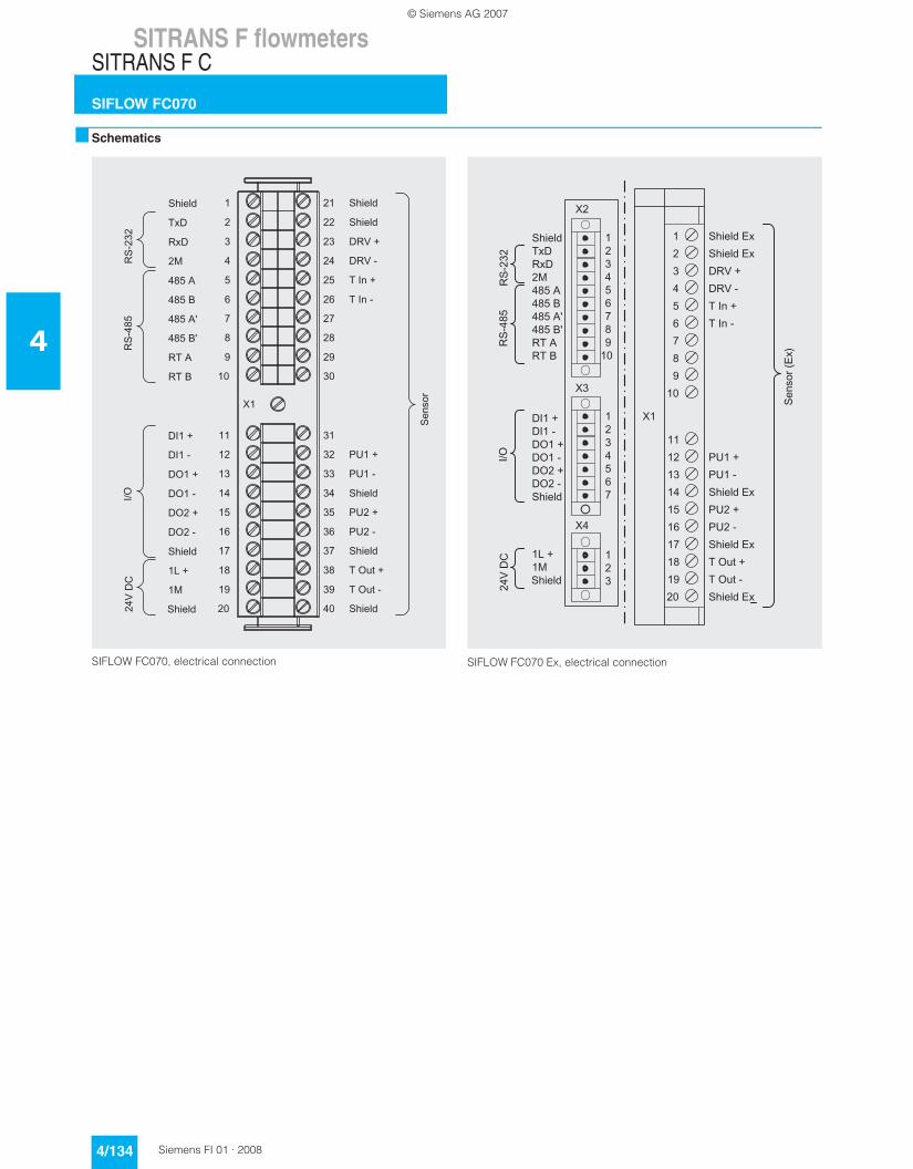
Schematics
SIFLOW FC070, electrical connection SIFLOW FC070 Ex, electrical connection
© Siemens AG 2007

SITRANS F flowmetersSITRANS F C
SITRANS FC300
4/135Siemens FI 01 · 2008
4
Overview
SITRANS FC300 is a new range of compact coriolis mass flow-meters sensors suitable for flow measurement of a variety kind of liquids and gases.
The sensor offers superior performance in terms of flow accu-racy, turn-down range and density accuracy. The ease of instal-lation through a plug & play interface ensures optimum perfor-mance and operation.
A new designed encapsulation in stainless steel with a surpris-ingly low weight of only 3.5 kg (7.7 lb), ensures a rigid and robust sensor performance for a wide range of applications.
Benefits
• High accuracy better than 0.1% of mass flow rate• Large dynamic turn down range better than 100:1• Densitometer performance available through a density accu-
racy better than 0.001 g/cm3 (0.000036 lb/inch3) with a re-peatability better than 0.0002 g/cm3 (0.0000072 lb/inch3)
• One tube without internal welds, reductions or flow splitters of-fers optimal hygiene, safety and CIP cleanability for food & beverage and pharmaceutical applications
• Larger wall thickness, ensures optimal lifetime and corrosion resistance and high pressure durability
• Balanced pipe design with little mechanical energy-loss, en-sures optimal performance and stability under non ideal and unstable process conditions (pressure, temperature, density-changes etc.)
• 4-wire Pt1000 temperature measurement ensures optimum accuracy on mass flow, density and fraction flow
• Multi-plug electrical connector & SENSORPROM enable true plug & play. Installation and commissioning in less than 10 min.
• Intrinsically safe Ex-design ia IIC as standard• Sensor pipe available in high quality AISI 316L stainless steel
1.4435 or Hastelloy C22 2.4602 offering optimum corrosion re-sistance
• Rugged and space saving sensor design in stainless steel matching all applications
• High pressure program as standard• The sensor calibration factor is also valid for gas measure-
ment
Application
The industry today has an increasing demand for mass flowme-ters with a reduced physical size without loss of performance. The meters must be suitable for installation in traditional process industry environment as well as OEM equipment for instance within automotive or appliance industry. Independent of industry application the meter must deliver accurate and reliable mea-surements. The new and versatile design of the FC300 offers this flexibility and the main applications for the SITRANS FC300 DN 4 can be found in:
Design
The FC300 sensor consists of a single tube bended in double omega pipe geometry, welded directly to the process connec-tors at each end. The sensor is available in 2 material configura-tions, AISI 316L or Hastelloy C22 with ¼”-NPT or G¼”-ISO pro-cess connections.
The enclosure is made of stainless steel AISI 316L 1.4409 with a grade of encapsulation of IP66/NEMA4. The enclosure has a very robust design and with an overall size of 130 x 200 x 60 mm (5.12“ x 7.87“ x 2.36“) the sensor is very compact and requires only little installation space.
The sensor can be delivered in a standard version with a maxi-mum liquid temperature of 115 °C (239 °F) or a high temperature version, with raised electrical connector for 180 °C (356 °F).
The sensor can be installed in horizontal or vertical position. The sensor can be mounted directly on any given plane surface or if desired with the enclosed quick release clamp fitting which, along with its compact design and multi-plug electrical connec-tor, will keep installation costs and time to a minimum.
Function
The measuring principle is based on coriolis force of movement, see “System information MASSFLO coriolis mass flowmeters”.
Integration
The sensor can be connected to all MASS 6000 transmitters for remote installation only.
All sensors are delivered with a SENSORPROM containing all in-formation about calibration data, identity and factory pre-pro-gramming of transmitter settings
Installation guidelines for SITRANS FC300 sensor
Horizontal installation as shown in figure A is recommended with gas or liquid applications.
This installation is also recommended when the flow is low or the liquid contains solid particles or air bubbles.
Horizontal installation as shown in figure B can be used for liquid applications especially where the flow velocity exceeds 1 m/s.
Chemical industry Liquid and gas measurement in normal as well as corrosive envi-ronments
Cosmetic industry Dosing of essence & fragrances
Pharmaceutical industry High speed dosing and coating of pills, filling of ampuls/injectors
Food & beverage industry Filling, dosing of flavorings, colors and additives, in-line density measurementMeasurement and dosing of li-quid or gaseous CO2
Automotive industry Fuel injection nozzle & pump test-ing, filling of AC units, engine consumption, paint robots, ABS test-beds
© Siemens AG 2007

SITRANS F flowmetersSITRANS F C
SITRANS FC300
4/136 Siemens FI 01 · 2008
4
Vertical installation as shown in figure C can be used for liquid or gas applications.
For liquid applications upwards flow is recommended to facili-tate the removal of air bubbles and to avoid partly emptying of the sensor.For gas applications we recommend to place the flow inlet high on the sensor and the outlet low to remove impurities and oil films.• To ensure that the sensor does not become partly empty, there
must be a sufficient counter-pressure on the unit min. 0.1 to 0.2 bar.
• Mount the sensor on a vibration free and plane wall or steel frame
• Locate the sensor low in the system in order to avoid under-pressure in the sensor separating air/gas in the liquid.
• Ensure that the sensor is not emptied of liquid (during normal operation) otherwise incorrect measurement will occur.
Horizontal mounting (fig. A)
Liquid or gas and low flow applications
Horizontal mounting (fig. B)
Liquid applications
Vertical mounting (fig. C)
Liquid and gas applications
Technical specifications
1) According to DIN 2413, DIN 174572) Housing is not rated for pressure containment.
Sensor size DN 4 (1/6“)
Mass flow
Measuring range 0 ... 350 kg/h (0 ... 772 lb/h)
Accuracy, mass flow 0.1% of rate
Repeatability 0.05 of rate
Max. zero point error 0.010 kg/h (0.022 lb/h)
Density
Density range 0 ... 2.9 g/cm3 (0 ... 0.105 lb/inch3)
Density error 0.0015 g/cm3
(0.000036 lb/inch3)
Repeatability error 0.0002 g/cm3
(0.0000072 lb/inch3)
Temperature
Standard -40 ... +115 °C (-40 ... +239 °F)
High temperature version -40 ... +180 °C (-40 ... +356 °F)
Temperature error 0.5 °C
Brix
Measuring range 0 ... 100 Brix
Brix error 0.3 Brix
Inside pipe diameter
Stainless steel version 3.5 mm (0.14“)
Hastelloy version 3.0 mm (0.12“)
Pipe wall thickness
Stainless steel version 0.25 mm (0.0098“)
Hastelloy version 0.5 mm (0.0196“)
Liquid pressure measuring pipe1)
Stainless steel 130 bar (1885 psi) at 20 °C (68 °F)
Hastelloy C22 410 bar (5945 psi) at 20 °C (68 °F)
Materials 1.4435 (AISI 316L) Stainless steel
Measuring pipe and connection 2.4602 (Hastelloy C22)
Enclosure2)
Material 1.4404 (AISI 316L) Stainless steel
Enclosure grade IP67/NEMA4
Connection thread
ISO 228/1 G¼” male
ANSI/ASME B1.20.1 ¼” NPT male
Ex approval EEx ia IIC T3-T6
05ATEX138072X
UL/CSA (under preparation)
Weight 3.5 kg (7.7 lb)
Dimensions 135 x 205 x 58 mm(5.31“ x 8.07“ x 2.28“)
© Siemens AG 2007

SITRANS F flowmetersSITRANS F C
SITRANS FC300
4/137Siemens FI 01 · 2008
4
Characteristic curves
Pressure drop
Stainless steel 316L
Hastelloy C22
Spare parts
Selection and Ordering data Order-No. Order code
SITRANS F C Flow sensors
SITRANS FC300 DN 4 (1/6“) sensor, without heating jacket1)
1) Not possible to order DN 4 sensor with heating jacket
F) 7ME4400-
77777 - 7A77 777
Pipe material and temperatureStainless steel 1.4435/316L115 °C (239 °F) 1 G180 °C (356 °F) 1 H
2.4602/Hastelloy C22115 °C (239 °F) 2 G180 °C (356 °F) 2 H
PressurePN 100 DPN 130 (316L) GPN 410 (C-22) Q
Process connectionPipe thread
G ¼“ male 1 0¼“ NPT male 1 1
ConfigurationStandard 1Density 2Brix/Plato 3
Fraction (specification required) 9 N 0 Y
CableNo cable A5 m (16 ft) cable B10 m (32 ft) cable C
25 m (82 ft) cable D
50 m (164 ft) cable E75 m (246 ft) cable F
150 m (492 ft) cable G
CalibrationStandard calibration 3 flow x 2 points 1Standard calibration matched pair 3 flow x 2 points
2
Accredited calibration matched pair 5 flow x 2 points (DANAK)
3
Extended calibration customer specified select Y60, Y61, Y62 or Y63 (see additional information)
8
Selection and Ordering data Order code
Additional informationPlease add “-Z“ to Order No. and specify Order code(s) and plain text.
Pressure testing certificate PED: 97/23/EC C11
Material certificate EN 10204-3.1B C12
Welding certificate NDT-Penetrant: ISO 3452 C13
Factory certificate according to EN 10204 2.2 C14
Factory certificate according to EN 10204 2.1 C15
Tag name plate, stainless steel Y17
Tag name plate, plastic Y18
Customer specific transmitter setup Y20
Customer specified, matched pair (5x2) Y60
Customer specified calibration (5x2) Y61
Customer specified, matched pair (10x1) Y62
Customer specified calibration (10x1) Y63
Special version Y99
Description Order No.F)
Multiple plug for cable mounting FDK-083H5056
Description Length Order No.
Cable with multiple plugStandard blue cable between MASS 6000 and MASS 2100, 5 x 2 x 0,34 mm2 twisted and screened in pairs. Temperature range -20 °C ... +110 °C(-4 °F ... +230 °F)
5 m (16.4 ft) FDK-083H3015
10 m (32.8 ft) FDK-083H3016
25 m (82 ft) FDK-083H3017
50 m (164 ft) FDK-083H3018
75 m (246 ft) FDK-083H3054
150 m (492 ft) FDK-083H3055
Description Order No.F)
2 kB SENSORPROM unit(Sensor Serial No. and Order No. must be specified by ordering)
FDK-083H4410
F) All products on this page subject to export regulations AL: 9I999, ECCN: N.
© Siemens AG 2007

SITRANS F flowmetersSITRANS F C
SITRANS FC300
4/138 Siemens FI 01 · 2008
4
Dimensional drawings
SITRANS FC300, dimensions in mm (inch)
© Siemens AG 2007

SITRANS F flowmetersSITRANS F C
MASSFLO MASS 2100 DI 1.5
4/139Siemens FI 01 · 2008
4
Overview
MASS 2100 DI 1.5 is suitable for low flow measurement applica-tions of a variety of liquids and gases.
The sensor offers superior performance in terms of flow accu-racy, turn-down range and density accuracy. The ease of instal-lation through a "plug & play" mechanical and electrical interface ensures optimum performance and operation.
The sensor delivers true multiparameter measurements i.e.: Mass flow, volume flow, density, temperature and fraction.
Benefits
• High accuracy better than 0.1% of mass flow rate • Large dynamic turn down range better than 500:1, from
65 kg/h to a few g/h• Densitometer performance available through a density accu-
racy better than 0.001 g/cm3 with a repeatability better than 0,0002 g/cm3
• Single continuous tube design, with no internal welds, reduc-tions or flow splitters offers optimal hygiene, safety and CIP cleanability for food & beverage and pharmaceutical applica-tions
• Market’s biggest wall thickness, ensuring optimal lifetime and corrosion resistance and high pressure durability
• Balanced pipe design with little mechanical energy-loss, en-sures optimal performance and stability under non ideal and unstable process conditions (pressure, temperature, density-changes etc.)
• 4-wire Pt1000 temperature measurement ensures optimum accuracy on mass flow, density and fraction flow
• Multi-plug electrical connector & SENSORPROM enables true "plug & play". Installation and commissioning in less than 10 min.
• Intrinsically safe EEx ia design as standard• Sensor pipe available in high quality AISI 316L stainless steel
1.4435 or Hastelloy C 22 2.4602 offering optimum corrosion resistance
• Dual-drive pick-up and driver construction facilitate ultra low-weight pipe construction giving the markets smallest and most stable zero point
• Rugged and space saving sensor design in stainless steel matching all environments
• High pressure program as standard• The sensor calibration factor is also valid for gas measure-
ment
Application
In many industries such as the food & beverage or pharamceu-tical industry, accurate recipe control means everything. The MASS 2100 DI 1.5 has demonstrated superiour performance in numerous applications and field trails relating to accuracy and turn down ratio. It is today the prefeered meter for research and development and mini-plant applications for liquid or gas mea-surement, where measuring small quantities is important.
Design
The MASS 2100 sensor consists of a single bent tube in a double omega pipe configuration, welded directly to the process con-nectors at each end.
The sensor is available in 2 material configurations, AISI 316L or Hastelloy C22 with ¼” NPT or ¼” ISO process connections.
The enclosure is made in stainless steel AISI 316L 1.4404 with a grade of encapsulation of IP65/NEMA 4.
The sensor is available in either a standard version with a maxi-mum liquid temperature of 125 °C (257 °F) or a high temperature version, with raised electrical connector for 180 °C (356 °F).
The sensor can be installed in horizontal or vertical position. The enclosed single quick release clamp fitting which, along with its compact design and single multi-plug electrical connector, will keep installation costs and time to a minimum as shown below.
The main applications for the MASS 2100 DI 1.5 sensor can be found in:
Chemical industry Liquid and gas measurement within Miniplant and R&D, dosing of additives and catalysts
Cosmetic industry Dosing of essence & fragrances
Pharmaceutical industry High speed dosing and coating of pills, filling of ampuls/injectors
Food & beverage industry Dosing of flavourings, colours and additives, density measurement, in-lineMeasurement of liquid or gaseous CO2
Automotive industry Fuel injection nozzle & pump test-ing, filling of AC units, engine con-sumption, paint robots, ABS test-beds
© Siemens AG 2007

SITRANS F flowmetersSITRANS F C
MASSFLO MASS 2100 DI 1.5
4/140 Siemens FI 01 · 2008
4
Function
The measuring principle is based on coriolis force of movement, see “System information MASSFLO coriolis mass flowmeters”.
Integration
The sensor can be connected to all MASS 6000 transmitters for remote installation only.
All sensors are delivered with a SENSORPROM containing all in-formation about calibration data, identity and factory pre-pro-gramming of transmitter settings
Installation guidelines MASS 2100 DI 1.5 (1/16“)
Installation of MASS 2100 sensor• The optimal installation is horizontal.
If vertical mounting is necessary, upward flow is recom-mended to facilitate the removal of air bubbles. To remove the air from the sensor the flow speed in the sensor must be at least 1 m/s.If there are solid particles in the liquid, especially in connec-tion with low flow, it is recommended that the sensor be mounted horizontally with inlet flange uppermost so that parti-cles are more easily flushed out. To ensure that the sensor does not become partially empty, there must be sufficient counter-pressure on the unit min. 0.1 to 0.2 bar (1.45 to 2.9 psi).
• Mount the sensor on a vibration-free wall or steel frame.• Locate the sensor low in the system in order to avoid an under-
pressure in the sensor separating air/gas in the liquid.• Ensure that the sensor is not emptied of liquid (during normal
operation) otherwise incorrect measurement will occur.
Horizontal
Liquid and gas application
Vertical
Liquid application (left), gas application (right)
Technical specifications
1) According to DIN 2413, DIN 174572) Housing is not rated for pressure containment.
For accuracy specifications see “System information MASSFLO”.
Pressure drop
MASS 2100 DI 1.5 (1/16“), pressure drop for density = 1000 kg/m3
Versions DI 1.5 (1/16“)
Inside pipe diameter (sensor con-sists of one continuous pipe)
1.5 mm (0.06”)
Pipe wall thickness 0.25 mm (0.010”)
Mass flow measuring range 0 ... 65 kg/h (0 ... 143 lb/h)
Density 0 ... 2.9 g/cm3 (0 ... 0.10 lb/inch3)
Fraction e.g. 0 ... 100 °Brix
Temperature
Standard -50 ... +125 °C (-58 ... +257 °F)
High temperature version -50 ... +180 °C (-58 ... +356 °F)
Liquid pressure measuring pipe 1)
Stainless steel 230 bar (3336 psi) at 20 °C (68 °F)
Hastelloy C-22 365 bar (5294 psi) at 20 °C (68 °F)
Materials
Measuring pipe and connection 1.4435 (AISI 316L) (stainless steel)
2.4602 (Hastelloy C-22)
Enclosure and enclosure material 2)
IP66/NEMA 4 and 1.4404 (AISI 316L) (stainless steel)
Connection thread
ISO 228/1 G¼” male
ANSI/ASME B1.20.1 ¼” NPT male
Cable connection Multiple plug connection to sen-sor 5 x 2 x 0.35 mm2 twisted and screened in pairs, ext. Ø 12 mm
Ex-version EEx ia IIC T3-T6, DEMKO 03 ATEX 135252X
Weight approx. 2.6 kg (5.73 lb)
1000500 200
100
50
20
10
5
1
∆p [bar]
100
10
1.0
0.1
0.010.1 1 10 70
Mass flow [kg/h]
Viscosity [cSt]
© Siemens AG 2007

SITRANS F flowmetersSITRANS F C
MASSFLO MASS 2100 DI 1.5
4/141Siemens FI 01 · 2008
4
1) Not possible to order DI 1.5 sensor with heat jacket
Please also see www.siemens.com/SITRANSForderingfor practical examples of ordering
Spare parts
Selection and Ordering data Order-No. Order code
SITRANS F C Flow sensors
MASSFLO 2100 DI 1.5 (1/16“) sensor, without heating jacket 1)
F) 7ME4100-
77777 - 7A77 777
Diameter
Stainless steel 1.4435/316LDI 1.5, max. 125 °C (257 °F) 1 ADI 1.5, max. 180 °C (356 °F) 1 B
2.4602/Hastelloy C22DI 1.5, max. 125 °C (257 °F) 2 ADI 1.5, max. 180 °C (356 °F) 2 B
Pressure
PN 100 DPN 230 (316L) LPN 365 (C-22) P
Process connection/flange
Pipe thread
G ¼“ male 1 0¼“ NPT male 1 1
Configuration
Standard 1Density 2Brix/Plato 3
Fraction (specification required) 9 N 0 Y
CableNo cable A5 m (16 ft) cable B10 m (32 ft) cable C
25 m (82 ft) cable D
50 m (164 ft) cable E75 m (246 ft) cable F
150 m (492 ft) cable G
Calibration
Standard calibration 3 flow x 2 points 1Standard calibration matched pair 3 flow x 2 points
2
Accredited calibration matched pair 5 flow x 2 points (DANAK)
3
Extended calibration customer specified select Y60, Y61, Y62 or Y63 (see additional information)
8
Selection and Ordering data Order code
Additional informationPlease add “-Z“ to Order No. and specify Order code(s) and plain text.
Pressure testing certificate PED: 97/23/EC C11
Material certificate EN 10204-3.1B C12
Welding certificate NDT-Penetrant: ISO 3452 C13
Factory certificate according to EN 10204 2.2 C14
Factory certificate according to EN 10204 2.1 C15
Tag name plate, stainless steel Y17
Tag name plate, plastic Y18
Customer specific transmitter setup Y20
Customer specified, matched pair (5x2) Y60
Customer specified calibration (5x2) Y61
Customer specified, matched pair (10x1) Y62
Customer specified calibration (10x1) Y63
Special version Y99
Description Order No.F)
Multiple plug for cable mounting FDK-083H5056
Description Length Order No.
Cable with multiple plugStandard blue cable between MASS 6000 and MASS 2100, 5 x 2 x 0,34 mm2 twisted and screened in pairs. Temperature range -20 °C ... +110 °C(-4 °F ... +230 °F)
5 m (16.4 ft) FDK-083H3015
10 m (32.8 ft) FDK-083H3016
25 m (82 ft) FDK-083H3017
50 m (164 ft) FDK-083H3018
75 m (246 ft) FDK-083H3054
150 m (492 ft) FDK-083H3055
Description Order No.F)
2 kB SENSORPROM unit(Sensor Serial No. and Order No. must be specified by ordering)
FDK-083H4410
F) All products on this page subject to export regulations AL: 9I999, ECCN: N.
© Siemens AG 2007

SITRANS F flowmetersSITRANS F C
MASSFLO MASS 2100 DI 1.5
4/142 Siemens FI 01 · 2008
4
Dimensional drawings
MASS 2100 DI 1.5 (1/16“)
Dimensions in mm (inch)
MASS 2100 DI 1.5 High temperature version to 180 °C (356 °F)
Dimensions in mm (inch)
© Siemens AG 2007

SITRANS F flowmetersSITRANS F C
MASSFLO MASS 2100 DI 3 to DI 40
4/143Siemens FI 01 · 2008
4
Overview
MASS 2100 DI 3 to DI 40 is suitable for accurate mass flow mea-surement of a variety of liquids and gases.
The sensor offers superior performance in terms of flow accu-racy, turn-down range and density accuracy. The ease of instal-lation through a "plug & play" mechanical and electrical interface ensures optimum performance and operation.
The sensor delivers true multi parameter measurements i.e.: Mass flow, volume flow, density, temperature and fraction.
Benefits
• High accuracy better than 0.1% of mass flow rate • Large dynamic turn down range better than 500:1• Densitometer performance available through a density accu-
racy better than 0.0005 g/cm3 with a repeatability better than 0.0001 g/cm3
• Single continuous tube design, with no internal welds, reduc-tions or flow splitters offers optimal hygiene, safety and CIP clean-ability for food & beverage and pharmaceutical applica-tions
• Markets biggest wall thickness, ensuring optimal lifetime and corrosion resistance and high pressure durability
• Full bore design provides lower pressure loss due to same in-ternal diameter throughout the entire sensor.
• Balanced pipe design with little mechanical energy-loss, en-sures optimal performance and stability under non ideal and unstable process conditions (pressure, temperature, density-changes etc.)
• 4-wire Pt1000 temperature measurement ensures optimum accuracy on mass flow, density and fraction flow
• Multi-plug electrical connector & SENSORPROM enables true plug&play. Installation and commissioning in less than 10 min.
• Intrinsically safe Ex-design ia IIC as standard, making service in hazardous area possible without having to demount the sensor if a compact Ex-d transmitter needs service
• Sensor pipe available in high quality AISI 316L stainless steel 1.4435 or Hastelloy C 22 2.4602 offering optimum corrosion resistance
• Centre-block design decouples process noise from the envi-ronment such as vibrations, pulsations, pressure shocks etc. making installation flexible and versatile
• Rugged and space saving sensor design in stainless steel matching all environments
• High pressure program as standard• The sensor calibration factor is also valid for gas measure-
ment• Uniform sensor interface matching all transmitter versions at
the same time whether it is compact IP67/NEMA 4X, compact Ex-d or remote installation, one sensor fits all
Application
Coriolis mass flowmeters are suitable for measuring all liquids and gases. The measurement is independent of changes in pro-cess conditions/parameters such as temperature, density, pres-sure, viscosity, conductivity and flow profile.
Due to this versatility the meter is easy to install and the coriolis flowmeter is recognized for its high accuracy in a wide turn down range which is a paramount in many applications.
The wide varity of combinations and versions from the modular system means that ideal adaptation is possible to each measur-ing task.
Design
The MASS 2100 sensor consists of a single bent tube in a double bent pipe configuration, welded directly to the process connec-tors at each end.The centre-block is brazed onto the sensor pipes from the out-side acting as a mechanical low pass filter.
The sensor is available in 2 material configurations, AISI 316L or Hastelloy C 22 with a wide variety of process connections.
The enclosure is made in stainless steel AISI 316L 1.4404 with a grade of encapsulation of IP66/NEMA 4.
The sensor is as standard EEx ia approved, intrinsically safe
The sensor can be installed in horizontal or vertical position. In horizontal position the sensor is self draining.
Heating Jacket: All the sensors MASS 2100, Di 3 to Di 40, can optionally be equipped with a heating coil to avoid solidification of sensitive fluids during down time or period between discon-tinuing processes. This feature gives the user an alternative to the costly electrical heating normally used, as gives the freedom to choose either hot water, superheated steam or hot oil, to main-tain a constant temperature inside the sensor.
The main applications of the coriolis flowmeter can be found in all industries, such as:
Chemical & pharma Detergents, bulk chemicals, phar-maceuticals, acids, alkalis
Food & beverage Dairy products, beer, wine, soft-drinks, plato/brix, fruit juices and pulps, bottling, CO2 dosing, CIP-liquids
Automotive Fuel injection nozzle & pump test-ing, filling of AC units, engine con-sumption, paint robots
Oil & gas Filling of gas bottles, furnace con-trol, CNG-dispensers, test separa-tors, LPG
Water & waste water Dosing of chemicals for water treatment
© Siemens AG 2007

SITRANS F flowmetersSITRANS F C
MASSFLO MASS 2100 DI 3 to DI 40
4/144 Siemens FI 01 · 2008
4
Function
The measuring principle is based on coriolis law of movement, see “System information MASSFLO coriolis mass flowmeters”.
Integration
The sensor can be connected to all MASS 6000 transmitters for compact as well as remote installation.
All sensors are delivered with a SENSORPROM containing all in-formation about calibration data, identity and factory pre-pro-gramming of transmitter settings.
Installation guidelines MASS 2100 DI 3 ... DI 40 (1/8” ... 1½”)
Installation of sensor
Horizontal (self-draining)
With low flow, horizontal mounting is recommended, as in this position air bubbles are easier to remove.
Vertical
If the liquid is volatile or contains solid particles, vertical mount-ing is not recommended.
Vibration
Always locate the flowmeter as far away as possible from com-ponents that generate mechanical vibration in the piping.
Cross talk
Cross talk between sensors mounted close to each other may disturb the measurement. To avoid cross talk never mount more than one meter on each frame and mount flexible hose connec-tions between the sensors as shown.
Zero point adjustment
To facilitiate zero point adjustment a shut-off valve should always be mounted in connection with the sensor as a proper zero point setting is essential for a good accuarcy.
© Siemens AG 2007

SITRANS F flowmetersSITRANS F C
MASSFLO MASS 2100 DI 3 to DI 40
4/145Siemens FI 01 · 2008
4
Technical specifications
1) Max. at 20 °C (68 °F), DIN 2413, DIN 174572) Other connections to order, see “Selection and Ordering data”3) Material, 1.4401 or corresponding
For accuracy specification see “System information MASSFLO”.
Versions mm (inch) DI 3 (1/8) DI 6 (¼) DI 15 (5/8) DI 25 (1) DI 40 (1½)
Inside pipe diameter (sen-sor consists of one continu-ous pipe)
mm (inch) 3.0 (0.12) 6.0 (0.24) 14.0 (0.55) 29.7 (1.17) 43.1 (1.70)
Pipe wall thickness mm (inch) 0.5 (0.02) 1.0 (0.04) 1.0 (0.04) 2.0 (0.08) 2.6 (0.10)
Mass flow measuring range
kg/h (lb/h) 0 ... 250 (0 ... 550) 0 ... 1,000 (0 ... 2,200)
0 ... 5,600 (0 ... 12,345)
0 ... 25,000 (0 ... 55,100)
0 ... 52,000 (0 ... 114,600)
Density g/cm3
(lb/inch3)0 ... 2.9 (0 ... 0.10)
Fraction e.g. °Brix 0 ... 100
Temperature
Standard °C (°F) -50 ... +180 °C (-58 ... +356 °F)
Liquid pressure measur-ing pipe 1)
Stainless steel bar (psi) 230 (3336) 265 (3844) 130 (1885) 110 (1595) 105 (1523)
Hastelloy C-22 bar (psi) 350 (5076) 410 (5946) 200 (2900) 185 (2683) not available
Materials
Measuring pipe, flange and thread connection
1.4435 (AISI 316L) (Stainless steel)
2.4602 (Hastelloy C-22) not available
Enclosure and enclosure material
IP65 (NEMA 4) and 1.4404 (AISI 316L) (Stainless steel), housing is not rated for pressure containment
Process connections 2)
Flange
EN 1092-1, PN 40 DN 10 DN 15 DN 25 DN 40
ANSI B16.5, Class 150 ½” ½” 1” 1½”
ANSI B16.5, Class 600 (Class 300)
½” ½” 1” 1½”
Dairy screwed connec-tion (PN 16/25/40) 3)
DIN 11851 DN 10 DN 15 DN 32 DN 40
ISO 2853/BS 4825 part 4 (SS3351)
25 mm 25 mm 38 mm 51 mm
Dairy clamp connection (PN 16) 3)
ISO 2852/BS 4825 part 3 (SMS3016)
25 mm 25 mm 38 mm 51 mm
Thread
ISO 228/1, PN 100 G¼” female G¼” male G½” male G1“ male G2“ male
ANSI/ASME B1.20.1, PN 100
¼” NPT female ¼” NPT male ½” NPT male 1“ NPT male 2“ NPT male
Cable connection Multiple plug connection to sensor 5 x 2 x 0.35 mm2 twisted and screened in pairs, ext. Ø 12 mm
Ex-version EEx ia IIC T3-T6, DEMKO 03 ATEX 135252X
Weight approx. kg (lb) 4 (8.8) 8 (17.6) 12 (26.5) 48 (105.8) 70 (154.5)
© Siemens AG 2007

SITRANS F flowmetersSITRANS F C
MASSFLO MASS 2100 DI 3 to DI 40
4/146 Siemens FI 01 · 2008
4
Pressure drop
MASS 2100 DI 3 (1/8”), pressure drop for density = 1000 kg/m3
MASS 2100 DI 6 (¼“), pressure drop for density = 1000 kg/m3
MASS 2100 DI 15 (½”), pressure drop for density = 1000 kg/m3
MASS 2100 DI 25 (1”), pressure drop for density = 1000 kg/m3
500100
20050 20
12
510
1000
10
1.0
0.13 10 100 300
Mass flow [kg/h]
Viscosity (cSt)∆p [bar]
10
1.0
0.110 100 1000
Mass flow [kg/h]
Viscosity [cSt]∆p [bar]
100050
0
5020
1
200100
∆p [ bar]
10
1.0
0.160 100 1000 6000
Mass flow [kg/h]
Viscosity [cSt]
1000500
5020
1
200
100
∆p [ bar]
10
1.0
0.1300 1000 10000 30000
Mass flow [kg/h]
Viscosity [cSt]
1000
500
5020
120
010
0
© Siemens AG 2007

SITRANS F flowmetersSITRANS F C
MASSFLO MASS 2100 DI 3 to DI 40
4/147Siemens FI 01 · 2008
4
MASS 2100 DI 40 (1½”), pressure drop for density = 1000 kg/m3
∆p [ bar]
10
1.0
0.1500 1000 10000 50000
Mass flow [kg/h]
Viscosity [cSt]
1000
500
5020
120
010
0
© Siemens AG 2007

SITRANS F flowmetersSITRANS F C
MASSFLO MASS 2100 DI 3 to DI 40
4/148 Siemens FI 01 · 2008
4
Selection and Ordering data Order-No. Order code
SITRANS F C sensors
MASS 2100 without heating jacket F) 7ME4100-
MASS 2100 heated, DN 15 connection F) 7ME4200-
MASS 2100 heated, ½ inch, ANSI B16.5 connection
F) 7ME4210-
77777 - 7777 777
Diameter
Stainless steel 1.4435/316LDI 3 (PN 100/PN 230) 1 C
DI 6 1 DDI 15 1 EDI 25 1 FDI 40 1 G
2.4602/Hastelloy C22DI 3 (PN 100/PN 350) 2 CDI 6 2 D
DI 15 2 EDI 25 2 F
Pressure
PN 16 (DI 6, DI 15, DI 25 and DI 40) APN 25 (DI 6, DI 15, DI 25 and DI 40) BPN 40 (DI 6, DI 15, DI 25 and DI 40) C
PN 100 (DI 3, DI 6, DI 15, DI 25 and DI 40) DPN 105 (DI 40, 2“, 316L) EPN 110 (DI 25, 1“, 316L) F
PN 130 (DI 15, ½“, 316L) GPN 185 (DI 25, 1“, Hastelly C-22) J
PN 200 (DI 15, ½“, Hastelly C-22) KPN 230 (DI 3, ¼“, 316L) LPN 265 (DI 6, ¼“, 316L) M
PN 350 (DI 3, ¼“, Hastelloy C-22) NPN 410 (DI 6, ¼“, Hastelloy C-22) Q
Class 150 (DI 6, DI 15, DI 25 and DI 40) RClass 600 (DI 6, DI 15, DI 25 and DI 40) S
Process connection/flange
Pipe thread
G ¼“ 1 0¼“ NPT 1 1G ½“ 1 2
½“ NPT 1 3G 1 1 41“ NPT 1 5
G 2“ 1 62“ NPT 1 7
Flange EN1092-1
DN 10 (PN 40/PN 100) 2 0DN 15 (PN 40/PN 100) 2 1DN 25 (PN 40/PN 100) 2 2
DN 40 (PN 40/PN 100) 2 3DN 50 (PN 40/PN 100) 2 4
Flange ASME/ANSI B 16.5
½“ (class 150/class 600) 3 0¾“ (class 150/class 600) 3 11“ (class 150/class 600) 3 2
1 ½“ (class 150/class 600) 3 32 “ (class 150/class 600) 3 4
Please also see www.siemens.com/SITRANSForderingfor practical examples of ordering
Dairy screwed connection DIN 11851
DN 10 (PN 40) 4 0DN 15 (PN 40) 4 1DN 25 (PN 40) 4 2
DN 32 (PN 40) 4 3DN 40 (PN 25) 4 4DN 50 (PN 25) 4 5
DN 65 (PN 25) 4 6
Dairy clamp connection ISO 2852
25 mm (PN 16) 5 038 mm (PN 16) 5 151 mm (PN 16) 5 2
Dairy screwed connection ISO 2853
25 mm (PN 16) 6 038 mm (PN 16) 6 151 mm (PN 16) 6 2
Configuration
Standard 1Density 2Brix/Plato 3
Fraction (specification required) 9 N 0 Y
Transmitter compact mounted on sensor
No transmitter, sensor only A
MASS 6000, Ex-d, stainless steel enclosure, 1 current, 1 freq./pulse and 1 relay output, 24 V AC/DC with EEx-de [ia/ib] T3 -T6 Ex-approval.
B
MASS 6000, IP67, Polyamide enclosure, cable glands M20, 1 current, 1 freq./pulse and 1 relay output, 24 V AC/DC.
C
MASS 6000, IP67, Polyamide enclosure, cable glands M20, 1 current, 1 freq./pulse and 1 relay output, 115/230 V AC 50/60 Hz
D
MASS 6000, IP67, Polyamide enclosure, cable glands ½" NPT, 1 current, 1 freq./pulse and 1 relay output, 24 V AC/DC
E
MASS 6000, IP67, Polyamide enclosure, cable glands ½" NPT, 1 current, 1 freq./pulse and 1 relay output, 115/230 V AC 50/60 Hz, ½" NPT
F
CableNo cable A5 m (16 ft) cable B10 m (32 ft) cable C
25 m (82 ft) cable D
50 m (164 ft) cable E75 m (246 ft) cable F
150 m (492 ft) cable G
Calibration
Standard calibration 3 flow x 2 points 1Standard calibration matched pair 3 flow x 2 points
2
Accredited calibration matched pair 5 flow x 2 points (DANAK)
3
Extended calibration customer specified select Y60, Y61, Y62 or Y63 (see additional information)
8
Selection and Ordering data Order-No. Order code
SITRANS F C sensors
MASS 2100 without heating jacket F) 7ME4100-
MASS 2100 heated, DN 15 connection F) 7ME4200-
MASS 2100 heated, ½ inch, ANSI B16.5 connection
F) 7ME4210-
77777 - 7777 777
F) Subject to export regulations AL: 9I999, ECCN: N.
© Siemens AG 2007

SITRANS F flowmetersSITRANS F C
MASSFLO MASS 2100 DI 3 to DI 40
4/149Siemens FI 01 · 2008
4
Selection and Ordering data
Accessories
Gaskets for MASS 2100
Spare parts
Dairy MLFB example
MASS 2100 7 M E 4 1 0 0 - 77C77 1 7A7
Stainless stell, DI 15 1 E
Dairy screwed connection DIN 11851, DN 15
4 1
MASS 6000 IP67 compact mounted D
Standard calibration 1
Selection and Ordering data Order code
Addtional informationPlease add “-Z“ to Order No. and specify Order code(s) and plain text.
Pressure testing certificate PED: 97/23/EC C11
Material certificate EN 10204-3.1B C12
Welding certificate NDT X-ray: EN 25817/BDI 3 sensor only: NDT-Penetrant: ISO 3452
C13
Factory certificate according to EN 10204 2.2 C14
Factory certificate according to EN 10204 2.1 C15
Tag name plate, stainless steel Y17
Tag name plate, plastic Y18
Customer specific transmitter setup Y20
Customer specified, matched pair (5x2) Y60
Customer specified calibration (5x2) Y61
Customer specified, matched pair (10x1) Y62
Customer specified calibration (10x1) Y63
Special version Y99
Description Dimension Order No.F)
Mating parts for hygienic fittings DIN 11851Includes:• 2 unions• 2 mating parts (for welding in)• 2 EPDM gaskets
DN 10 FDK-085U1016
DN 15 FDK-085U1017
DN 25 FDK-085U1019
DN 32 FDK-085U1020
DN 40 FDK-085U1021
DN 50 FDK-085U1022
DN 65 FDK-085U1023
Mating parts for hygienic clamp ISO 2852Includes:• 2 clamps• 2 mating parts• 2 EPDM gaskets
25 mm FDK-085U1029
40 mm FDK-085U1031
50 mm FDK-085U1032
Description Dimension Order No.F)
2 EPDM gaskets with collar for mounting set DIN 11851
DN 10 FDK-085U1006
DN 15 FDK-085U1007
DN 25 FDK-085U1009
DN 32 FDK-085U1010
DN 40 FDK-085U1011
DN 50 FDK-085U1012
DN 65 FDK-085U1013
Description Length Order No.F)
Multiple plug for cable mounting FDK-083H5056
Cable with multiple plugStandard blue cable between MASS 6000 and MASS 2100, 5 x 2 x 0,34 mm2 twisted and screened in pairs. Temperature range -20 °C ... +110 °C(-68 °F ... +230 °F)
5 m (16.4 ft) FDK-083H3015
10 m (32.8 ft) FDK-083H3016
25 m (82 ft) FDK-083H3017
50 m (164 ft) FDK-083H3018
75 m (246 ft) FDK-083H3054
150 m (492 ft) FDK-083H3055
Adapter for MASS 2100 FDK-083L8889
2 kB SENSORPROM unit(Sensor Serial No. and Order No. must be specified by ordering)
FDK-083H4410
F) All products on this page subject to export regulations AL: 9I999, ECCN: N.
© Siemens AG 2007

SITRANS F flowmetersSITRANS F C
MASSFLO MASS 2100 DI 3 to DI 40
4/150 Siemens FI 01 · 2008
4
Dimensional drawings
MASS 2100 sensor
Dimension in mm (inch)
Sensor size
Connections L1mm
L2mm
L3mm
H1mm
B1mm
D1mm
D2mm
D3mm
D4mm
D5mm
DN (inch) Type Pressure rating Size
DI 3(1/8“)
Pipe thread ISO 228/1 - G¼ PN 100 ¼” 400 280 75.0 60 0 21.3 104 - - -
Pipe thread ANSI/ASME B 1.20.1 - ¼” NPT
PN 100 ¼” 400 280 75.0 60 0 21.3 104 - - -
DI 6(¼“)
Flange EN 1092-1 PN 40 DN 10 560 390 62.0 40 12 17.0 104 90.0 60.0 14.0
Flange ANSI B16.5 Class 150 ½“ 624 390 62.0 40 12 17.0 104 88.9 60.5 15.7
Flange ANSI B16.5 Class 600 ½“ 608 390 62.0 40 12 17.0 104 95.3 66.5 15.7
Screwed connection DIN 11851 PN 40 DN 10 532 390 62.0 40 12 17.0 104 - - -
Clamp ISO 2852 PN 16 25 mm 570 390 62.0 40 12 17.0 104 - - -
DI 15(½“)
Flange EN 1092-1 PN 40 DN 15 620 444 75.0 44 20 21.3 129 95.0 65.0 14.0
Flange ANSI B16.5 Class 150 ½“ 639 444 75.0 44 20 21.3 129 88.9 60.5 15.7
Flange ANSI B16.5 Class 600 ½“ 660 444 75.0 44 20 21.3 129 95.3 66.5 15.7
Screwed connection DIN 11851 PN 40 DN 15 586 444 75.0 44 20 21.3 129 - - -
Clamp ISO 2852 PN 16 25 mm 624 444 75.0 44 20 21.3 129 - - -
DI 25(1“)
Flange EN 1092-1 PN 40 DN 25 934 700 74.5 126 25 33.7 219 115.0 85.0 14.0
Flange ANSI B16.5 Class 150 1“ 967 700 74.5 126 25 33.7 219 108.0 79.2 15.7
Flange ANSI B16.5 Class 600 1“ 992 700 74.5 126 25 33.7 219 124.0 88.9 19.1
Screwed connection DIN 11851 PN 40 DN 32 922 700 74.5 126 25 33.7 219 - - -
Clamp ISO 2852 PN 16 38 mm 940 700 74.5 126 25 33.7 219 - - -
DI 40(1½“)
Flange EN 1092-1 PN 40 DN 40 1064 850 71.5 180 0 48.3 273 150.0 110.0 18.0
Flange ANSI B16.5 Class 150 1½“ 1100 850 71.5 180 0 48.3 273 127.0 98.6 15.7
Flange ANSI B16.5 Class 600 1½“ 1128 850 71.5 180 0 48.3 273 155.4 114.3 22.4
Screwed connection DIN 11851 PN 25 DN 50 1090 850 71.5 180 0 48.3 273 - - -
Clamp ISO 2852 PN 25 51 mm 1062 850 71.5 180 0 48.3 273 - - -
© Siemens AG 2007

SITRANS F flowmetersSITRANS F C
MASSFLO MASS 2100 DI 3 to DI 40
4/151Siemens FI 01 · 2008
4
Sensor size
Connections L1inch
L2inch
L3inch
H1inch
B1inch
D1inch
D2inch
D3inch
D4inch
D5inch
DN (inch) Type Pressure rating Size
DI 3(1/8“)
Pipe thread ISO 228/1 - G¼ PN 100 ¼” 15.75 11.02 2.95 2.36 0 0.84 4.09 - - -
Pipe thread ANSI/ASME B 1.20.1 - ¼” NPT
PN 100 ¼” 15.75 11.02 2.95 2.36 0 0.84 4.09 - - -
DI 6(¼“)
Flange EN 1092-1 PN 40 DN 10 22.05 15.35 2.44 1.57 0.47 0.67 4.09 3.54 2.36 0.55
Flange ANSI B16.5 Class 150 ½“ 24.57 15.35 2.44 1.57 0.47 0.67 4.09 3.5 2.38 0.62
Flange ANSI B16.5 Class 600 ½“ 23.94 15.35 2.44 1.57 0.47 0.67 4.09 3.75 2.62 0.62
Screwed connection DIN 11851 PN 40 DN 10 20.94 15.35 2.44 1.57 0.47 0.67 4.09 - - -
Clamp ISO 2852 PN 16 25 mm 22.44 15.35 2.44 1.57 0.47 0.67 4.09 - - -
DI 15(½“)
Flange EN 1092-1 PN 40 DN 15 24.41 17.48 2.95 1.73 0.79 0.84 5.08 3.74 2.56 0.55
Flange ANSI B16.5 Class 150 ½“ 25.16 17.48 2.95 1.73 0.79 0.84 5.08 3.5 2.38 0.62
Flange ANSI B16.5 Class 600 ½“ 25.98 17.48 2.95 1.73 0.79 0.84 5.08 3.75 2.62 0.62
Screwed connection DIN 11851 PN 40 DN 15 23.07 17.48 2.95 1.73 0.79 0.84 5.08 - - -
Clamp ISO 2852 PN 16 25 mm 24.57 17.48 2.95 1.73 0.79 0.84 5.08 - - -
DI 25(1“)
Flange EN 1092-1 PN 40 DN 25 36.77 27.56 2.93 4.96 0.98 1.33 8.62 4.53 3.35 0.55
Flange ANSI B16.5 Class 150 1“ 38.07 27.56 2.93 4.96 0.98 1.33 8.62 4.25 3.12 0.62
Flange ANSI B16.5 Class 600 1“ 39.06 27.56 2.93 4.96 0.98 1.33 8.62 4.88 3.50 0.75
Screwed connection DIN 11851 PN 40 DN 32 36.30 27.56 2.93 4.96 0.98 1.33 8.62 - - -
Clamp ISO 2852 PN 16 38 mm 37.01 27.56 2.93 4.96 0.98 1.33 8.62 - - -
DI 40(1½“)
Flange EN 1092-1 PN 40 DN 40 41.89 33.46 2.81 7.09 0 1.9 10.75 5.91 4.33 0.71
Flange ANSI B16.5 Class 150 1½“ 43.31 33.46 2.81 7.09 0 1.9 10.75 5 3.88 0.62
Flange ANSI B16.5 Class 600 1½“ 44.41 33.46 2.81 7.09 0 1.9 10.75 6.12 4.50 0.88
Screwed connection DIN 11851 PN 25 DN 50 42.91 33.46 2.81 7.09 0 1.9 10.75 - - -
Clamp ISO 2852 PN 25 51 mm 41.81 33.46 2.81 7.09 0 1.9 10.75 - - -
© Siemens AG 2007

SITRANS F flowmetersSITRANS F C
MASSFLO MASS 2100 DI 3 to DI 40
4/152 Siemens FI 01 · 2008
4
MASS 2100 sensor with “heating jacket”
Dimensions in mm (inch)
MASS 2100 and MASS 6000 Ex-d compact version
Dimensions in mm (inch)
MASS 2100 and MASS 6000 IP67 compact version
Dimensions in mm (inch)
Sensor size Connec-tions heated
L5 L3 H3 B2 D6 D7 D8
DN (inch) Type Pressure rating Size mm (inch) mm (inch) mm (inch) mm (inch) mm (inch) mm (inch) mm (inch)
DI 3 (1/8“) EN 1092-1 PN 40 DN 15 234 (9.21) 75 (.2.95) 122 (4.8) 22 (0.87) 95 (3.74) 65.0 (2.56) 14.0 (0.55)
ANSI B16.5 Class 150 ½" 234 (9.21) 75 (2.95) 131.6 (5.18) 22 (0.87) 88.9 (3.5) 60.5 (2.38) 15.7 (0.62)
DI 6 (¼“) EN 1092-1 PN 40 DN 15 234 (9.21) 62 (2.44) 112 (4.41) 22.7 (0.89) 95 (3.74) 65.0 (2.56) 14.0 (0.55)
ANSI B16.5 Class 150 ½" 234 (9.21) 62 (2.44) 121.6 (4.79) 22.7 (0.89) 88.9 (3.5) 60.5 (2.38) 15.7 (0.62)
DI 15 (½“) EN 1092-1 PN 40 DN 15 234 (9.21) 75 (2.95) 126.5 (4.98) 31.5 (1.24) 95 (3.74) 65.0 (2.56) 14.0 (0.55)
ANSI B16.5 Class150 ½" 234 (9.21) 75 (2.95) 136.1 (5.36) 31.5 (1.24) 88.9 (3.5) 60.5 (2.38) 15.7 (0.62)
DI 25 (1“) EN 1092-1 PN 40 DN 15 420 (16.54) 75 (2.93) 213.6 (8.41) 60 (2.36) 95 (3.74) 65.0 (2.56) 14.0 (0.55)
ANSI B16.5 Class 150 ½" 420 (16.54) 75 (2.93) 223.2 (8.79) 60 (2.36) 88.9 (3.5) 60.5 (2.38) 15.7 (0.62)
DI 40 (1½“) EN 1092-1 PN 40 DN 15 500 (19.68) 71 (2.81) 267.5 (10.53) 43 (1.69) 95 (3.74) 65.0 (2.56) 14.0 (0.55)
ANSI B16.5 Class 150 ½" 500 (19.68) 71 (2.81) 277.1 (10.91) 43 (1.69) 88.9 (3.5) 60.5 (2.38) 15.7 (0.62)
Sensor size [DN (inch)]
L3[mm (inch)]
H5[mm (inch)]
H6[mm (inch)]
H5 + H6[mm (inch)]
3 (1/8) 75 (2.95) 82 (3.23) 307 (12.1) 389 (15.32)
6 (¼) 62 (2.44) 72 (2.83) 317 (12.48) 389 (15.32)
15 (½) 75 (2.95) 87 (3.43) 328 (12.91) 414 (16.30)
25 (1) 75 (2.95) 173 (6.81) 332 (13.07) 504 (19.84)
40 (1½) 75 (2.95) 227 (8.94) 332 (13.07) 558 (21.97)
Sensor size [DN (inch)]
L3[mm (inch)]
H5[mm (inch)]
H6[mm (inch)]
H5 + H6[mm (inch)]
3 (1/8) 75 (2.95) 82 (3.23) 246 (9.69) 328 (12.91)
6 (¼) 62 (2.44) 72 (2.83) 256 (10.08) 328 (12.91)
15 (½) 75 (2.95) 87 (3.43) 267 (10.51) 353 (13.90)
25 (1) 75 (2.95) 173 (6.81) 271 (10.67) 443 (17.44)
40 (1½) 75 (2.95) 227 (8.94) 271 (10.67) 497 (19.57)
© Siemens AG 2007

SITRANS F flowmetersSITRANS F C
MASSFLO MASS MC2
4/153Siemens FI 01 · 2008
4
Overview
MASS 2100 MC2 DN 50 to DN 150 (2” to 6”) and MC2 Hygienic (EHEDG certified) from DN 20 to DN 80 (¾“ to 3“) is suitable for accurate mass flow measurement of a variety of liquids and gases.
The sensor offers superior performance in terms of flow accu-racy, turn-down range and density accuracy. The very compact sensor construction makes installation and commissioning of even the largest sizes very straight forward and easy.
The sensor delivers true multi parameter measurements i.e.: Mass flow, volume flow, density, temperature and fraction flow.
Benefits
• High accuracy better than 0.15% of mass flow rate • Large dynamic turn down range • Densitometer performance available through a density accu-
racy better than 0.001 g/cm3
• Space saving split-flow sensor design facilitating low pressure loss
• Parallel S-tube design and optimal oriented inductive sensors enhances accuracy and turn-down range
• Self draining in both horizontal and vertical position• Rigid enclosure design reduces the influence from pipeline vi-
bration and thermal stress• 4-wire Pt100 temperature measurement ensures optimum ac-
curacy on mass flow, density and fraction flow• SENSORPROM enables true "plug & play". Installation and
commissioning in less than 10 min.• Safe Ex-design EEx em [ib] IIC• Sensor pipe available in high quality AISI 316L stainless steel
1.4571 or Hastelloy C 4 2.4610 offering optimum corrosion re-sistance
• The sensor calibration factor is also valid for gas measure-ment
Application
Coriolis mass flowmeters are suitable for measuring all liquids and gases. The measurement is independent of changes in pro-cess conditions/parameters such as temperature, density, pres-sure, viscosity, conductivity and flow profile.
Due to this versatility the meter is easy to install and the coriolis flowmeter is recognized for its high accuracy in a wide turn-down range which is a paramount in many applications.
The wide varity of combinations and versions from the modular system means that ideal adaptation is possible to each measur-ing task.
Design
The MC2 sensor consists of 2 parallel measuring pipes, welded directly onto a flow-splitter at each end to eliminate a direct cou-pling to the process connectors and significantly reduce effects from external vibrations.
The flow-splitters are welded onto a rigid sensor housing which acts as a mechanical low pass filter.
The sensor is available in 2 material configurations, AISI 316L or Hastelloy C4 with a wide variety of process connections.
The enclosure is made of stainless steel AISI 304 1.4301 with a grade of encapsulation of IP67/NEMA 4.
The sensor is Ex-approved EEx em [ib] IIC
The sensor can be installed in horizontal or vertical position, and is self draining in both positions.
Due to the increased safety concept used on the bigger sized sensors, the MASS 6000 19" or MASS 6000 IP67 standard ver-sions can be connected but has to be remote mounted in the safe area. For all non hazardous applications the complete MASS 6000 transmitter program can be used.
The main applications of the coriolis flowmeter can be found in all industries, such as:
Chemical & pharma Detergents, bulk chemicals, phar-maceuticals, acids, alkalis
Food & beverageEDEHG certified
Dairy products, beer, wine, soft-drinks, plato/brix, fruit juices and pulps, bottling, CO2 dosing, CIP-liquids
Oil & gas Gas measurement, furnace con-trol, test separators, LPG, oil bun-kering
Water & waste water Dosing of chemicals for water treatment
Hazardous areaZone 1 + 2
Safe area
© Siemens AG 2007