AFP-2800-2802 Manual V5_08
158
AFP-2800/2802 OPERATION,INSTALLATION &PROGRAMMING MANUAL P/N DOC-01-010 ECN11-0058 26-Oct-11 Rev: 5.08
-
Upload
victor-chua -
Category
Documents
-
view
86 -
download
2
Transcript of AFP-2800-2802 Manual V5_08

AFP-2800/2802OPERATION, INSTALLATION
& PROGRAMMING MANUAL
P/N DOC-01-010 ECN11-0058
26-Oct-11 Rev: 5.08

Documentation Feedback
Your feedback helps us keep our documentation up to date and accurate. If you have any comments orsuggestions about our printed manuals you can email us.
Please include the following information:
• Product name and version number (if applicable)• Manual part number and revision (found on the front cover)• Page number• Brief description of the content you think should be improved or corrected• Your suggestion for how to correct/improve documentation
Send email messages to:
Please note this email address is for documentation feedback only. If you have any technical issues, pleasecontact your nearest branch for technical support.

AFP-2800/2802 Manual – P/N DOC-01-010 3
Installation PrecautionsAdherence to the following will aid in problem-free installation with long-term reliability:
WARNING - Several different sources of power can be connected to the fire alarm control panel.Disconnect all sources of power before servicing. Control unit and associated equipment may be damaged byremoving and/or inserting cards, modules, or interconnecting cables while the unit is energized. Do not attempt toinstall, service, or operate this unit until manuals are read and understood.
Verify that wire sizes are adequate for all initiating and indicating device loops. Most devices cannot toleratemore than a 10% voltage drop from the specified device voltage.
Like all solid state electronic devices, this system may operate erratically or can be damaged when subjectedto lightning induced transients. Although no system is completely immune from lightning transients andinterference, proper grounding will reduce susceptibility. Overhead or outside aerial wiring is not recommended,due to an increased susceptibility to nearby lightning strikes. Consult with the Technical Services Department ifany problems are anticipated or encountered.
Disconnect AC power and batteries prior to removing or inserting circuit boards. Failure to do so can damagecircuits.
Remove all electronic assemblies prior to any drilling, filing, reaming, or punching of the enclosure. Whenpossible, make all cable entries from the sides or rear. Before making modifications, verify that they will notinterfere with battery, transformer, or printed circuit board location.
Do not over tighten screw terminals. Over tightening may damage threads, resulting in reduced terminalcontact pressure and difficulty with screw terminal removal.
This system contains static-sensitive components. Always ground yourself with a proper wrist strap beforehandling any circuits so that static charges are removed from the body. Use static suppressive packaging toprotect electronic assemblies removed from the unit.
Follow the instructions in the installation, operating and programming manuals. These instructions must befollowed to avoid damage to the control panel and associated equipment. FACP operation and reliability dependupon proper installation.
This equipment must be correctly programmed and installed to suit the specific application. Pleaseensure correct operational parameters are set prior to commissioning. If further details on programming optionsare required, please consult the programming manual or contact our helpful technical support personnel.
EMC WARNING:
This equipment may radiate radio frequency energy. It may also be affected by radio frequency energy and, if notinstalled and operated in accordance with the manufacturer’s instructions, may cause interference to radiocommunications. It has been tested and found to comply with the Class A radiated and conducted EMIrequirements of AS/NZS CISPR 22:2009 (including Amendments 1 & 2) as well as the EMI susceptibilityrequirements of Clause C3.5 in AS4428.0:1997.
Radio communication devices should not be used in the vicinity of fire panels or associated ancillary devices andsystems.
This is a Class A product. In a domestic environment this product may cause radio interference in which case theuser may be required to take adequate measures.

AFP-2800/2802 Manual – P/N DOC-01-010 4
Table of Contents
1 EMERGENCY OPERATION ................................................................................................................................... 7
2 PLACING INTO OPERATION CHECKLIST......................................................................................................... 8
2.1 PRE POWER-UP CHECKS ........................................................................................................................................ 82.2 POWER UP CHECKLIST........................................................................................................................................... 82.3 FAULT RECORD ..................................................................................................................................................... 9
3 SYSTEM DESCRIPTION ....................................................................................................................................... 10
4 SPECIFICATIONS & APPROVALS...................................................................................................................... 11
4.1 GENERAL SPECIFICATIONS (SUBJECT TO CHANGE WITHOUT NOTICE):..................................................................... 114.2 APPROVALS INFORMATION .................................................................................................................................. 114.3 ELECTRICAL SPECIFICATIONS .............................................................................................................................. 12
4.3.1 Power Supply.............................................................................................................................................. 124.3.2 Termination board (FIM) ............................................................................................................................ 134.3.3 Panel Expansion Relays .............................................................................................................................. 134.3.4 LCM / LEM Addressable Loop Controller Modules ..................................................................................... 134.3.5 NCM Network control module ..................................................................................................................... 134.3.6 Fan control module ..................................................................................................................................... 144.3.7 AZM 8 module............................................................................................................................................. 144.3.8 ACM-16AT Annunciator.............................................................................................................................. 144.3.9 ACM-32A Annunciator................................................................................................................................ 144.3.10 SCS-8 Annunciator...................................................................................................................................... 154.3.11 LDM-R32 Annunciator................................................................................................................................ 154.3.12 LCD-80 Display interface............................................................................................................................ 15
5 COMPATIBLE DEVICES....................................................................................................................................... 16
5.1 ADDRESSABLE DEVICES ...................................................................................................................................... 165.2 CONVENTIONAL DETECTORS ............................................................................................................................... 165.3 COMPATIBLE BATTERIES ..................................................................................................................................... 17
6 SYSTEM CAPACITY AND EXPANDABILITY.................................................................................................... 18
6.1 BASE SYSTEM ..................................................................................................................................................... 186.2 EXPANSION PCBS ............................................................................................................................................... 186.3 ANALOG ADDRESSABLE LOOPS ........................................................................................................................... 196.4 ANNUNCIATORS .................................................................................................................................................. 196.5 FIELD MODULES.................................................................................................................................................. 196.6 DISPLAY INTERFACES .......................................................................................................................................... 20
7 PANEL OPERATION.............................................................................................................................................. 21
7.1 FRONT PANEL DISPLAY ....................................................................................................................................... 217.1.1 Selecting Screen Items................................................................................................................................. 217.1.2 Scrolling Through Lists ............................................................................................................................... 217.1.3 Entering Information................................................................................................................................... 227.1.4 System Counters.......................................................................................................................................... 227.1.5 Point Formats ............................................................................................................................................. 227.1.6 Annunciator Addressing .............................................................................................................................. 24
7.2 FIREFIGHTERS MODE ........................................................................................................................................... 257.3 SERVICE MENU MODE ......................................................................................................................................... 26
7.3.1 Service Menu structure................................................................................................................................ 267.3.2 Service Menu .............................................................................................................................................. 287.3.3 Service Menu – List..................................................................................................................................... 297.3.4 Service Menu – Isolate ................................................................................................................................ 517.3.5 Service Menu – Config ................................................................................................................................ 597.3.6 Service Menu – Analog................................................................................................................................ 687.3.7 Service Menu – Global ................................................................................................................................ 757.3.8 Service Menu – Diagnostics ........................................................................................................................ 827.3.9 Service Menu – Network.............................................................................................................................. 857.3.10 Service Menu – log off................................................................................................................................. 88

AFP-2800/2802 Manual – P/N DOC-01-010 5
8 PROGRAMMING.................................................................................................................................................... 89
8.1 CONTROL SCRIPTS & VIRTUAL POINTS................................................................................................................. 898.1.1 Writing Scripts ............................................................................................................................................ 908.1.2 Using zone numbers in scripts: .................................................................................................................... 908.1.3 Making an output latch................................................................................................................................ 908.1.4 ANY Operator ............................................................................................................................................. 918.1.5 TIM Operator.............................................................................................................................................. 918.1.6 ‘S’ Pre-Operator......................................................................................................................................... 928.1.7 Scripting Examples...................................................................................................................................... 92
8.2 NETWORK POINTS (WHERE APPLICABLE) .............................................................................................................. 938.2.1 Special Net Points ....................................................................................................................................... 94
9 APPENDIX............................................................................................................................................................... 95
9.1 ZONE OPTION EXPLANATIONS ............................................................................................................................. 959.1.1 AVF functional description.......................................................................................................................... 959.1.2 Timed AZF Functional Description.............................................................................................................. 95
9.2 PASSWORD ACCESS LEVELS................................................................................................................................. 969.3 LCD80 OPERATION ............................................................................................................................................. 97
9.3.1 LCD80 – Terminal Mode............................................................................................................................. 979.3.2 Annunciator Mode....................................................................................................................................... 99
9.4 RECOMMENDED CABLING REQUIREMENTS ..........................................................................................................1029.4.1 RS-485 Ring Communication Cabling.........................................................................................................1029.4.2 Addressable Loop Cabling..........................................................................................................................1039.4.3 NOTI.FIRE.NET Network cabling ..............................................................................................................104
9.5 INTELLIGENT SENSING FEATURES .......................................................................................................................1059.5.1 FlashScan Detector LED Operation ...........................................................................................................1059.5.2 Detector Initialisation ................................................................................................................................1059.5.3 Self-Optimizing Pre-Alarm .........................................................................................................................1059.5.4 Detector Sensitivity ....................................................................................................................................1059.5.5 Drift Compensation....................................................................................................................................1089.5.6 Fault Codes................................................................................................................................................109
9.6 PANEL CONNECTION DIAGRAMS: ........................................................................................................................1119.6.1 Main Termination Board (FIM)..................................................................................................................1119.6.2 CPU...........................................................................................................................................................1159.6.3 Loop Interface Module (LIM) .....................................................................................................................1169.6.4 Analog LCM and LEM Terminations ..........................................................................................................1179.6.5 Noti.Fire.Net™ ..........................................................................................................................................121
9.7 MODEM/PRINTER/HLI INTERFACE ......................................................................................................................1259.7.1 Modem Interface ........................................................................................................................................1259.7.2 Printer/Pager/HLI Interface .......................................................................................................................126
9.8 BATTERY CALCULATIONS...................................................................................................................................1289.8.1 Quiescent Current Calculation:..................................................................................................................1289.8.2 Alarm Current Calculation:........................................................................................................................1289.8.3 Battery Capacity Requirements: .................................................................................................................1289.8.4 Power Supply Capacity Requirements: .......................................................................................................128
9.9 FIELD REPLACEMENT PARTS:..............................................................................................................................1299.10 FIELD MODULE CONNECTION DIAGRAMS ............................................................................................................130
9.10.1 AZM-8 .......................................................................................................................................................1309.10.2 FAN Controller ..........................................................................................................................................131
9.11 ANNUNCIATOR CONNECTION ..............................................................................................................................1329.11.1 RS485 Comms and Power Connections.......................................................................................................1329.11.2 ACM-16AT (16 buttons, 32 LED’s).............................................................................................................1339.11.3 ACM-32A (32 Red LED’s)..........................................................................................................................1349.11.4 SCS-8 (8 Fan Controls) ..............................................................................................................................1359.11.5 LDM-32 (Expansion Relay Driver Board)...................................................................................................1369.11.6 LDM-R32 (32 Expansion Relays)................................................................................................................1379.11.7 LCD80 Display Interface............................................................................................................................138
9.12 PANEL EXPANSION RELAYS ................................................................................................................................1399.13 ANALOG ADDRESSABLE DEVICES .......................................................................................................................140
9.13.1 Detector Bases ...........................................................................................................................................1409.13.2 B5241EFT Isolator Base ............................................................................................................................1419.13.3 Isolation Module ISO-X..............................................................................................................................142

AFP-2800/2802 Manual – P/N DOC-01-010 6
9.13.4 Relay Module FRM-1 .................................................................................................................................1439.13.5 Control Module FCM-1..............................................................................................................................1449.13.6 Zone Module FZM-1 ..................................................................................................................................1459.13.7 Monitor Module FMM-1 ............................................................................................................................1469.13.8 Mini Monitor Module FMM-101.................................................................................................................1479.13.9 XP10-M (10 x Monitor Module) .................................................................................................................1489.13.10 XP6-MA (6 x Conventional Zone Interface Module) ................................................................................1499.13.11 XP6-R (6 x Relay Module) ......................................................................................................................1509.13.12 XP6C (6 x Control Module) ....................................................................................................................1519.13.13 FDMR-1 (2 x Monitor & 2 x Relay) ........................................................................................................1529.13.14 Fan Controls Connection Diagram.........................................................................................................153
9.14 NPS POWER SUPPLY CONNECTIONS ....................................................................................................................1549.14.1 Connection to IFS-714 Termination Board .................................................................................................1549.14.2 Connection to IFS-724 Termination Board .................................................................................................155

Emergency Operation
AFP-2800/2802 Manual – P/N DOC-01-010 7
1 EMERGENCY OPERATION
Isolate Bells Press: EXT BELL ISOLATE
EXT BELL ISOLATE LED will light The external bells & panel buzzer will stop A subsequent alarm will restart the panel buzzer but not the bells The bell isolate can be toggled by pressing the button a second time
Isolate Warning System Press: WARN SYS ISOLATE
WARN SYS ISOLATE LED will light The warning system will stop A subsequent alarm will restart the panel uzzer but not the warning
system The warning system isolate can by toggled by pressing the button a
second time
Acknowledging an Alarm Select the Alarm using the PREV , NEXT buttons
Press: ACK to acknowledge
This will individually acknowledge alarms Once all alarms are acknowledged the alarm LED will go steady
Resetting an Alarm Select the Alarm using the PREV , NEXT buttons
Press: RESET then press ACK to confirm the resetting
This will individually acknowledge and reset alarms Resets zone in alarm and clears all alarm inputs in the zone If alarm is still present, the zone(s) will either stay in alarm or re-
alarm again after about 15 seconds
Isolate an Alarm Select the Alarm using the PREV , NEXT buttons
Press: ISOL then press ACK to confirm the isolation
Isolates the point or zone in alarm and clears it’s alarm outputs Isolating a zone automatically acknowledges and isolates all points
in the zone

Placing Into Operation
AFP-2800/2802 Manual – P/N DOC-01-010 8
2 PLACING INTO OPERATION CHECKLIST
2.1 PRE POWER-UP CHECKS
System general appearance good
Cabinet colour and condition good
Cabinet keyed 003
All circuit boards firmly fastened
Manual call point fitted & functional
Viewing window clear and firmly secured
Cable entries adequately sealed
240 VAC cabling correctly terminated
All earthing secured
Power supply securely mounted
Power supply correctly wired
All ribbon cables firmly secured
All other components securely inserted
LCM boards correctly addressed and all analogue loops have been tested as per section 9.6.4.2
AFP-2800/2802 manufacturing label affixed
You are now ready to power up the AFP-2800/2802 Fire Indicator Panel.
Note: When re-booting the panel, power off for at least 10 seconds or LCM modules might not operate correctly.
2.2 POWER UP CHECKLIST
Ensure batteries are disconnected.
Turn mains switch To "ON"
After a few seconds, some power-up information should be displayed on the LCD screen, which will then
clear and display the alarm screen.
Under normal conditions the “NO ALARMS” message will be displayed.
The indicator LED’s on the rear of the CPU board will flash on and off.
The MAINS ON and FIRE FIGHTER lamps will be lit.
Connect the batteries.
Caution!! Incorrect polarity of batteries may cause permanent and serious damage to the system.
Check for system faults by pressing, “Service Menu”, “List”, “Faults”. If there are any faults, either rectify
or note in fault log on following page
YOU ARE NOW READY TO COMMENCE USING THE AFP-2800/2802 FIRE PANEL.

Placing Into Operation
AFP-2800/2802 Manual – P/N DOC-01-010 9
2.3 FAULT RECORD
FAULT CORRECTION DATE
TESTS SATISFACTORILY COMPLETED.
TESTED BY
SIGNATURE
DATE OF TEST
If all faults have been rectified and all tests are completed satisfactorily, the AFP-2800/2802 is now ready foroperation.

System Description
AFP-2800/2802 Manual – P/N DOC-01-010 10
3 SYSTEM DESCRIPTION
The AFP-2800/2802 is a microprocessor based distributed Fire Detection/Alarm System. The panel comprisesmultiple microprocessors for sharing the processing load both within the panel and in the field modules usingproprietary communications protocols, thus the term “distributed system”.
The main panel communicates with the intelligent field devices via the RS485 communications ring. Each fielddevice can have multiple inputs and outputs. These inputs and outputs can include (but are not limited to) smokeor heat detector circuits, bells and air conditioning controls.
The RS485 communications ring can support up to 100 distributed field modules and up to 50 panel annunciatorsand 32 LCD80 units in terminal mode. The number of LCD-80s and modules on the ring will affect panelperformance and should be considered when designing the system.
In addition to the distributed conventional communication ring, the panel can support up to 10 loops of Analogaddressable points using various protocols including the proprietary Notifier FlashScan protocol. Each loop cansupport 159 detectors and 159 modules.
In its maximum configuration, the AFP-2800 can support more than 802 Conventional Detection Circuits, morethan 400 Programmable Relay Outputs and 3,180 Analog addressable points. AFP-2802 supports a maximum of396 Analog addressable points.
All of this data is stored in a large database and text based scripts are continuously processed to implement thelogic of input and output functions similar to a programmable logic controller (PLC).
The system’s configuration data and event history is stored in non-volatile “Flash” memory, which does not rely onbattery power for its backup. The operating system is also stored in flash memory so there is no need for EPROMchanges to upgrade the firmware.
Note: Loops 3 to 10are only available onAFP-2800

Specifications & Approvals
AFP-2800/2802 Manual – P/N DOC-01-010 11
4 SPECIFICATIONS & APPROVALS
4.1 GENERAL SPECIFICATIONS (SUBJECT TO CHANGE WITHOUT NOTICE):
Cabinet Zinc Sealed SteelPowder CoatedHinged Inner DoorHinged Outer Door
Primary Microprocessor MC68EC000
Memory Type Non-volatile 16Mbit Flash; 1 Mbyte SRAM
Liquid Crystal Display LED Backlit 1/4 VGA graphical
Environmental Dry cold/heat: -10 °C to +55 °CDamp heat: +40 °C @ 93% Relative Humidity.
IP Rating IP 30
4.2 APPROVALS INFORMATION
Manufacturer: Notifier Fire Systems9 Columbia WayNorwest Business ParkNSW 2153 AustraliaPhone: +61-2-9899-4155Fax: +61-2-9899-4156
Product Name: Notifier Inertia AFP-2800 (formerly Notifier Inertia DFP-2800)
Approved to: AS4428.1 1999
Approval Report #: XF1769/R2 - Scientific Services Laboratory
ActivFire Listing No: AFP-1459
Approved to: NZS 4512:2003
Approval Report #: 05-527699.00 - Opus International Consultants Limited, Central Laboratories
Panel Serial #: ________________________
Date of Manufacture: ________________________
EMC WARNING:
This equipment may radiate radio frequency energy. It may also be affected by radio frequency energy and, ifnot installed and operated in accordance with the manufacturer’s instructions, may cause interference toradio communications. It has been tested and found to comply with the Class A radiated and conducted EMIrequirements of AS/NZS CISPR 22:2009 (including Amendments 1 & 2) as well as the EMI susceptibilityrequirements of Clause C3.5 in AS4428.0:1997.
Radio communication devices should not be used in the vicinity of fire panels or associated ancillary devicesand systems.
This is a Class A product. In a domestic environment this product may cause radio interference in which casethe user may be required to take adequate measures.

Specifications & Approvals
AFP-2800/2802 Manual – P/N DOC-01-010 12
4.3 ELECTRICAL SPECIFICATIONS
Note: All functions and specifications described in this Operators Manual are subject to change without notice.
44..33..11 PPOOWWEERR SSUUPPPPLLYY
Parameter PS243(3Amp)
PS249(9Amp)
NPS-2(2.6amp)
NPS-5(5.5amp)
NPS-11(11.7amp)
Input Voltage 240V AC +/-10%
240V AC +/-10%
110 or 240(SW select)
Universal Universal
Input Range 216V AC to254V AC
216 V AC to254V AC
85-132/170-264VAC(SW select)
85-264VACAuto Ranging
88-264VACAuto Ranging
Output Voltage 24V DC nom. 24V DC nom. 24V DC nom. 24V DC nom. 24V DC nom.
27.6V DC noload
27.6V DC noload
27.3V DC noload
27.3V DC noload
27.3V DC noload
26.5 V DC fullload
26.5V DC fullload
27.3V DC fullload
27.3V DC fullload
27.3V DC fullload
AdjustableRange
12V DC to 30VDC
12V DC to 30VDC
+/-10% +/-10% 26V to 32V
Rated CurrentOf Power Supply
3.0A @ 26.5VDC
9.0A @ 26.5VDC
2.6A @ 27V DC 5.5A @ 27V DC 11.7 @ 27V DC
OverloadCurrent Device
7.4A @ ShortCircuit
20A @ ShortCircuit
105% to 150%of rated power –auto recoveryafter faultremoval
105% to 150%of rated power –auto recoveryafter faultremoval
105% to 135%of rated power –auto recoveryafter faultremoval
SecondaryTransformerFuse
5A 15A N/A N/A N/A
Max Ripple 150mV p-p 150mV p-p 120mV p-p 150mV p-p 200mV p-p
Load Regulation 2% 2% ± 0.5% ± 0.5% ± 0.5%
Line Regulation 2% 2% ± 0.5% ± 0.5% ± 0.2%
Efficiency >80% >80% 82% 84% 88%
Battery Test Internal: 15ohms
Internal: 15ohms
External Load External Load External Load
Battery TestRelay ContactRating
10A 15A N/A N/A N/A
Indicators Mains On,Output On
Mains On,Output On
Mains On,Charger Fault,Battery Fault,Battery test,Batt test inhibit
Mains On,Charger Fault,Battery Fault,Battery test,Batt test inhibit
Mains On,Charger Fault,Battery Fault,Battery test,Batt test inhibit
Status Indicators By ExternalInterface or FIP
By ExternalInterface or FIP
Onboard LED orExternalInterface or FIP
Onboard LED orExternalInterface or FIP
Onboard LED orExternalInterface or FIP
Environmental -10C to +55CDry heat+ 40C @ 93%RH
-10C to +55CDry heat+ 40C @ 93%RH
-10C to +55CDry heat+ 40C @ 93%RH
-10C to +55CDry heat+ 40C @ 93%RH
-10C to +55CDry heat+ 40C @ 93%RH
WARNING: Severe damage may occur if the batteries are connected incorrectly.
Note: When annunciators or field modules are powered from external power supplies, use a separate conductor toconnect the main power supply common terminal (-0V) to the remote power supplies common terminal (-0V).

Specifications & Approvals
AFP-2800/2802 Manual – P/N DOC-01-010 13
44..33..22 TTEERRMMIINNAATTIIOONN BBOOAARRDD ((FFIIMM))
Supply Inputrequirements
22 to 28V dc – fused at 9A (self-resetting)55mA max (without CPU board or field loops connected)210mA max (with CPU board, without field loops connected)
Alarm Inputs Two conventional Alarm Zone inputs are provided, detecting opencircuit fault, alarm, and normal. Each input is monitored and requires a4K7 (nom) EOL resistor.
PowerOutputs
Auxiliary Power Output 20-28V 1A max24V dc & 5V dc Power to Ring Expander BoardsCPU power supply – 5V DC± 5% 3A
AlarmOutputs
4 x 1A monitored outputs (Bell & 3 spares – 4k7 EOL resistor)4 x ELV 1A relay contact outputs (Common Alarm, Fault plus 2 spare)
Communications Link
EIA485 on dual ports24Vdc (nom) 2A (max)Note: Up to 100 field modules may be installed. Additional auxiliarypower supply(s) may be required, depending on the number of fieldmodules installed.
Indications LED indications of relay outputs, fuses, ring power and ground fault
44..33..33 PPAANNEELL EEXXPPAANNSSIIOONN RREELLAAYYSS
Panel Expansion Relays (XR)IFS-803 and IFS-717
Up to 64 x 30Vdc @ 1A non-monitored relaycontact outputs via 8 x IFS-803/IFS-717 relayboards
44..33..44 LLCCMM // LLEEMM AADDDDRREESSSSAABBLLEE LLOOOOPP CCOONNTTRROOLLLLEERR MMOODDUULLEESS
Minimum Nominal Maximum
Operating voltage (V dc) 20.6 24 29
Loop communications voltage 15 24 32
Loop current limit (mA) 340 400 430
LCM/LEM Pair (Q Current) 140 200
Communications Link EIA485 on dual ports
LED Indications Green – Heart beat / Onboard 5Vdc supply OKAmber – Ground fault / faulty card detected
44..33..55 NNCCMM NNEETTWWOORRKK CCOONNTTRROOLL MMOODDUULLEE
NCM-W Supports twisted-pair wire medium, data is regenerated ateach node. 312.5K baud transmission rate.
NCM-F Supports fibre-optic medium (62.5/125 or 50/125micrometres – multimode). Single mode available. 312.5Kbaud transmission rate. Data is regenerated at each node.
HS-NCM High-speed data communications (12 Mb wire, 100 MbMF/SF fibre). Multi-mode fibre optic (MF), single-mode fibreoptic (SF),wire (W), or a combination of W/MF/SFcommunications path.

Specifications & Approvals
AFP-2800/2802 Manual – P/N DOC-01-010 14
44..33..66 FFAANN CCOONNTTRROOLL MMOODDUULLEE
Supply Input IFS700: 20 to 28Vdc55mA max (no relays energised)130mA max (all inputs and relays energised)
IFS710: 15 to 28Vdc55mA max (no relays energised)130mA max (all inputs and relays energised)
Inputs 3 x Opto Isolated 4k7 EOL
Outputs 3 x ELV 1A relay contact outputs (Max 30 Vdc or 24 Vac)
Communications Link EIA485 on dual ports
Indications LED indications on: Inputs,OutputsRX/TXPowerFault
44..33..77 AAZZMM 88 MMOODDUULLEE
Supply Input IFS701: 20 to 28V DC90mA max (no relays energised)155mA max (all relays energised)
IFS711: 15 to 28V DC80mA max (no relays energised)125mA max (all relays energised)238mA max (all AZF & relays energised)43mA max (no relays energised, all AZF disabled)
Inputs 8 conventional alarm inputsMonitoring – Open Circuit, Alarm, Fault
Outputs 4 x ELV 1A relay contact outputs (Max 30 VDC or 24 VAC)
Communications Link EIA485 on dual ports
Indications LED indications on: Outputs, RX/TX, Power,Fault
44..33..88 AACCMM--1166AATT AANNNNUUNNCCIIAATTOORR
Supply Input 20V to 28Vdc40mA standby180mA alarm (All LED’s on)
Communications Link EIA485 multi-dropped
44..33..99 AACCMM--3322AA AANNNNUUNNCCIIAATTOORR
Supply Input 20V to 28Vdc40mA standby180mA alarm (All LED’s on)
Communications Link EIA485 multi-dropped

Specifications & Approvals
AFP-2800/2802 Manual – P/N DOC-01-010 15
44..33..1100 SSCCSS--88 AANNNNUUNNCCIIAATTOORR
Supply Input 20V to 28Vdc33mA standby20mA max current per LED when LED ON
Communications Link EIA485 multi-dropped
44..33..1111 LLDDMM--RR3322 AANNNNUUNNCCIIAATTOORR
Supply Input 20V to 28Vdc40mA Standby200mA Alarm (32 relays energised)
Communications Link EIA485 multi-dropped
Relay contacts max 1A @ 30Vdc
44..33..1122 LLCCDD--8800 DDIISSPPLLAAYY IINNTTEERRFFAACCEE
Supply Input 20V to 28Vdc100mA Standby100mA Alarm
Communications Link EIA485 multi-dropped

Compatible Devices
AFP-2800/2802 Manual – P/N DOC-01-010 16
5 COMPATIBLE DEVICES
5.1 ADDRESSABLE DEVICES
MAKE MODEL TYPE MODEL NUMBER(S)
ANALOG ADDRESSABLE DETECTORS
Notifier Thermal Fixed Temp FST-751, FST-851, FST-851H, FST-851WP,FDX-851
Notifier Thermal Rate Of Rise FDX-751, FST-751R, FST-851R, FST-851R-WP,FDX-851R
Notifier Smoke Photo-Optical FSP-751, FSP-851, SDX-851
Notifier Smoke Ionisation FSI-751, FSI-851Notifier Smoke VIEW LPX-751L, FSL-751
Notifier Smoke Duct FSD-751P, DNR, DNRWNotifier Combination Acclimate FAPT-751, FAPT-851
Notifier Combination HARSH FSH-751Notifier Smoke Beam FSB-200, FSB-200s
Notifier Combination CO, Photo, Heat, IR FSC-851, SDX-751CTEM
ANALOG ADDRESSABLE MODULES
Notifier Input Module Conventional Zone Interface FZM-1
Notifier Input Module Monitor MMX-1, FMM-1Notifier Input Module Mini Monitor MMX-101, FMM-101
Notifier Output Module Relay CMX-2, FRM-1Notifier Output Module Control Output CMX-2, FCM-1
Notifier Input Module 5 x Mini Monitor XP5-MNotifier Output Module 5 x Relay/Control Output XP5-C
Notifier Input Module 6 x Conventional Zone Interface XP6-MANotifier Input Module 10 x Mini Monitor XP10-M
Notifier Output Module 6 x Relay XP6-RNotifier Output Module 6 x Control Output XP6-CNotifier Input/Output Module 2 x Monitor, 2 x Relay FDMR-1
Notifier Input module Manual Call Point FSM-500K, WCP-5ANotifier Sounder/Strobe Sounder and/or Strobes DBS24AL, ABS32, ABSB32, AWB32, AWS32,
AWSB32
LOOP ISOLATORS
Notifier Module Loop Isolator ISO-X, M700XE
Notifier Detector Base Loop Isolator B524IEFT
5.2 CONVENTIONAL DETECTORS
MAKE MODEL TYPE MODEL NUMBER(S)
System Sensor Thermal Type A 5451AUS, 51A51System Sensor Thermal Type B 4451AUS, 51B51
System Sensor Thermal Type B Sealed 885WP-BSystem Sensor Thermal Type C 51C51
System Sensor Thermal Fixed TEMP 63o
5151AUSSystem Sensor Thermal ROR 63
o5151RAUS
System Sensor Thermal Fixed TEMP 90o
5151HAUSSystem Sensor Thermal ROR 90
o5151HRAUS
System Sensor Smoke Photo-Optical 2151AUS,2151BAUSSystem Sensor Smoke Ionisation 1151AUSSystem Sensor Smoke Beam BEAM1224(S)
System Sensor Smoke Duct DH-100LP, D2Notifier Input Manual Call Point M400KR
Hochiki Thermal Type A DCD-A, DCC-A, DCA-B-60R Mk V
Hochiki Thermal Type B DFJ-60B, DFE-60B, DFG-60BLKJHochiki Thermal Type C DCD-C, DCC-C, DCA-B-90R Mk I
Hochiki Thermal Type D DFJ-90D, DFE-90DHochiki Smoke Ionisation SIJ-ASN, SIH-AM
Hochiki Smoke Photo Optical SLR-AS, SLK-A

Compatible Devices
AFP-2800/2802 Manual – P/N DOC-01-010 17
5.3 COMPATIBLE BATTERIES
In general, any Sealed Lead Acid (SLA) battery, or Wet Lead Acid battery designed for stationary use iscompatible with the AFP2800/2802 Fire Indicator Panel. The use of Nickel Cadmium batteries is notrecommended.
Manufacturer Type Number Voltage Capacity (Ah) Qty Required
Olympic Batteries SLA CJ12-7 12 7 2
Olympic Batteries SLA CJ12-12 12 12 2
Olympic Batteries SLA CJ12-18 12 18 2
Olympic Batteries SLA CJ12-26 12 26 2
Olympic Batteries SLA CJ12-33 12 33 2
Olympic Batteries SLA CJ12-40 12 40 2
Olympic Batteries SLA CJ12-85 12 85 2
Olympic Batteries SLA CJ12-100 12 100 2
NOTES:
Automotive batteries must not be used. There is a risk of explosion if battery is replaced by an incorrect type.
Dispose of used batteries according to Manufacturer Instructions
The use of Nickel Cadmium batteries is not recommended.
The batteries could be seriously and permanently damaged if they are permitted to discharge below 20V DCwhen placed in series.
The NPS series of power supplies will only charge the battery if the terminal voltage is above 12V whenmeasured across 2 batteries in series.

System Capacity And Expandability
AFP-2800/2802 Manual – P/N DOC-01-010 18
6 SYSTEM CAPACITY AND EXPANDABILITY
6.1 BASE SYSTEM
Item Description Notes
Communications Ring RS485 communications ring to supportUp to 100 Field ModulesUp to 50 Annunciators
8 System Outputs 4 x Monitored Outputs. Bell Output 3 Additional
programmable outputs4 x Clean contact relays
General Alarm Output General Fault Output 2 x programmable outputs
Fault output is normallyenergised using V5.00and above firmware.
Max contact rating of allrelays 1A @ 30Vdc.
Power Supply 2.6 A power supply and batterychargerFused 27.3Vdc outputs
A larger power supplymay be required if totalmodule load exceeds2A. Power supplies upto 11.7A are available.
2 Local AZF’s AZF 1AZF 2
2 RS232 communicationports
Laptop interfaceSystem event printerRemote terminal mode
Keyboard Interface PS2 QWERTY IBM PC keyboard
System Memory Approx. 4300 Named pointsApprox. 4000 Control scripts4000 History events
6.2 EXPANSION PCBS
Item Description Notes
Loop Interface Module(LIM)
Interface module to communicate withup to 5 x pairs of Notifier LCM/LEMmodules. I.e. total of 10 FlashScanAnalog addressable loops for AFP-2800 and a total of 4 CLIP Analogaddressable loops for the AFP-2802.
Each Analogaddressable loopsupports up to 159detectors and 159addressable modulesusing the NotifierFlashScan protocol or99 detectors and 99modules using the CLIPprotocol.
Network InterfaceModule (NIM)
Interface module to communicate withthe Network Control Module (NCM)
AFP-2800 only.AFP-2802 does notsupport Networking.
Panel Expansion Relays(IFS803 or IFS-717)
Relay card with 8 relays – contactrating is 1A @ 24Vdc
Up to 8 IFS-803/IFS-7178-way relay boards canbe added

System Capacity And Expandability
AFP-2800/2802 Manual – P/N DOC-01-010 19
6.3 ANALOG ADDRESSABLE LOOPS
Item Description Notes
Loop Control Module(LCM/ELCM)
Loop Controller for Loops 1,3,5,7,9 Max 5 per AFP-2800Max 1 per AFP-2802
Loop Expander Module(LEM)
Loop Controller for Loops 2,4,6,8,10 Max 5 per AFP-2800Max 1 per AFP-2802LEM “piggybacks”under the LCM.
6.4 ANNUNCIATORS
Item Description NotesACM32 Annunciator 32 Red LED A maximum of 50
annunciators can beconnected to thecommunications ring.
ACM16AT Annunciator 16 x Pushbutton inputs16 x Red LED16 x Yellow LED
SCS-8 Annunciator 8 x 3 Position switches8 x Red LED8 x Yellow LED8 x Green LED1 x Fire Trip (A/C) Reset switch1 x Fire Trip (A/C) Activated/Latched LED
SCS-8L Annunciator 24 x LED outputs & 25 digital inputsLDM-32 Annunciator 32 x LED outputs (Open Collector)LDM-R32 Annunciator 32 x Relay outputs rated to 1A @ 30Vdc
6.5 FIELD MODULES
Item Description NotesAZM-8 8 x AZF inputs (4k7 EOL resistor)
4 x Programmable Relay OutputsA maximum of 100field modules can beconnected to thecommunications ring.Larger/external powersupplies and separatefeeds are required forsystems with a largenumber of modules orlong cable runs.
The RS485 signal isregenerated at eachfield module.
Fan Controller (FAN-C) 3 x Inputs (Opto-isolated, not monitored)3 x Programmable Relay outputs
Note: Please note that the FAN-C module has been discontinued and will not be supplied for new installations.
When annunciators or field modules are powered from external power supplies, use a separate conductor toconnect the main power supply common terminal (-0V) to the remote power supplies common terminal (-0V).

System Capacity And Expandability
AFP-2800/2802 Manual – P/N DOC-01-010 20
6.6 DISPLAY INTERFACES
Item Description Notes
LCD80 Terminal mode display interface (seeLCD 80 manual)
A maximum of 32display interfaces canbe installed on thecommunications ring.Address 201 to 239
LCD80 Annunciator mode display interface (seeLCD 80 manual)
A maximum of 32display interfaces canbe installed on thecommunications ring.Address 101 to 139

Panel Operation
AFP-2800/2802 Manual – P/N DOC-01-010 21
7 PANEL OPERATION
7.1 FRONT PANEL DISPLAY
The AFP-2800/2802 is fitted with a LED backlit 1/4 VGA resolution graphical LCD screen allowing ease of use forthe operator by displaying multiple lines of information. The AFP-2800/2802 uses the concept of “hard” and “soft”buttons.
A “hard” button is one which is labelled with a fixed function (e.g. EXT BELL ISOLATE ).The functions of these
buttons do not change.
A “soft” button is one of the five buttons along the bottom of the LCD display. The function of the button maychange depending on the screen being displayed at the time. To indicate the button function, its label is changedby software, and displayed along the bottom line of the LCD as a pictorial representation of a button. Not allbuttons are shown on a screen, and the unlabelled buttons will have no effect if pressed.
Rather than having a cluttered front keypad fascia with letters numbers and function keys, the AFP-2800/2802accepts a standard PC101 style keyboard plugged directly into the CPU to allow full QWERTY functionaccessibility for programming and diagnostic test.
The LCD display is used to display information about the status of the system, field devices, and programmingmenus. The layout of the front keypad provides a “Fire-fighter's Facility” in accordance with AS4428. The purposeof this facility is to provide a uniform display for all fire alarm panels to assist Fire fighters during a response. Thethick red border signifies the fire-fighters area and provides alarm-based functions for the fire fighter.
The mode select buttons (bottom right) will toggle the system in between fire-fighters mode and the service menuwhere routine service and diagnostic tests can be performed. If there are any active and unacknowledged alarmson the system, the system will switch to and remain in fire-fighters mode until all alarms are acknowledged orreset.
77..11..11 SSEELLEECCTTIINNGG SSCCRREEEENN IITTEEMMSS
Selecting a screen item may be done in two ways
1. On a screen where the functions are numbered (e.g. Service Menu screen), pressing the number in front ofthe appropriate item will immediately select that item.
2. On a screen with UP/DOWN facility, pressing the UP or DOWN (or PREV / NEXT ) button will move the
highlighted cursor up or down the list. When the SELECT button is pressed, the highlighted item will then be
selected.
77..11..22 SSCCRROOLLLLIINNGG TTHHRROOUUGGHH LLIISSTTSS
When a list of points is displayed on the screen, you can scroll through the list by pressing the UP or DOWN (or
PREV / NEXT ) button. This will move the highlighted cursor up or down the list. If the button is held down, the
cursor will scroll more quickly and if it is held down for several seconds, the list will scroll page by page, enablingrapid access to item near the end of a long list.
When accessing the history List (which is a first-in, first-out list), simply press Page Up at the top of the list to be
immediately taken to the last page of the list.

Panel Operation
AFP-2800/2802 Manual – P/N DOC-01-010 22
77..11..33 EENNTTEERRIINNGG IINNFFOORRMMAATTIIOONN
On screens where character information needs to be entered, such as point labels, this must be done using anexternal QWERTY style keyboard plugged into the PS2 keyboard plug on the rear of the CPU panel. On screens(e.g. menus, change time/date) that require only numbers to be entered, the ten digit numeric keypad can beused.
77..11..44 SSYYSSTTEEMM CCOOUUNNTTEERRSS
On the top right hand side of all screens are the system counters showing the total number ofalarms, faults, isolates and non-alarm (active) events on the system at any time. If a device isboth isolated and in fault it will increment both counters. For more information as to which pointsare isolated, refer to the list menus.
77..11..55 PPOOIINNTT FFOORRMMAATTSS
There are three different types of point in the AFP-2800/2802 system – real (or physical) points, virtual (softwaregenerated) points and network points.
All points on the distributed ring and the Analog addressable loops are real points. Distributed points on fieldmodules are controlled and referred to in “R.M.IO” format. i.e.: Ring.Module.I/O – where I/O can consist of input,output or AZF. Analog addressable points on the addressable loops are controlled and referred to in “Loop, I/Oformat” i.e. Loop I/O where I/O can consist of module or detector number.
Virtual points are referred to as VPx where x can range from 1 to 1000. Virtual points are actually the output froma script equation and are discussed later in this manual (refer to page 96).
Network points are referred to as NPx where x can range from 1 to 1000. Each network node can have up to 1000Netpoints. Network points are real or virtual points mapped at any network node that is required to interact withother network nodes (refer to page 93).
Examples are as follows:
Point to be referred to Syntax
Ring 1, Module 1, Output 1 1.1.O1
Ring 1, Module 20, AZF input 1 (AZM-8) 1.20.Z1
Ring 1, Module 30, input 1 (FAN-C) 1.30.I1
Ring 1, Annunciator 1 (module 101), Output 1 (led #1) 1.101.O1
Ring 1, Annunciator 50 (module 150), Input 1 (button #1) 1.150.I1
Loop 1 Detector 1 L1D1
Loop 1 Module 1 L1M1
Expansion relay 1 XR1
Virtual point 1 VP1
Network point 1 on Node 1 N1.NP1
A = 2F = 5I = 10N = 5

Panel Operation
AFP-2800/2802 Manual – P/N DOC-01-010 23
System points will be displayed and can be referred to as follows:
Description Syntax Comments
On Board AZF’s 2 AZF’s on termination BoardAZF #1 0.1.Z1 Ring 0 Module 1, zone 1AZF #2 0.1.Z2 Ring 0 Module 1, zone 2
On Board Relays 8 Relays on termination BoardRelay 1 to 8 on FIM 0.4.O1 to 0.4.O8 Ring 0 Module 4, output 1
Ring 0 Module 4, output 8Distributed Field Modules Up to 100 modules
AZF 1.1.Z1 8 AZF points per AZM8moduleDin 1.1.I1 3 Din Per Fan Control ModuleDout 1.1.O1 4 Dout Per AZM-8
3 Dout Per Fan Control Module
Annunciator Up to 50 AnnunciatorsInputs 1.101.I1 16 Din per 16AT, 24 Din Per SCS-8Outputs 1.101.O1 32 Dout Per 16AT, 24 Dout Per SCS-8, 32
Dout Per ACM32AAnalog Addressable Devices Up to 10 Loops
Detectors L1D1 159 Detectors Per LoopModules L1M1 159 Modules Per Loop
Virtual Points VPn n can range up to 1000
Network Points NPn n can range up to 1000
Expansion Relays XRn n can range up to 64
System ParametersCommon Alarm CACommon Fault CFCommon Isolate CIBattery Fault BFCharger Fault CLMains On MOExt. Bell Isolated BIWarning System Isolated WI

Panel Operation
AFP-2800/2802 Manual – P/N DOC-01-010 24
77..11..66 AANNNNUUNNCCIIAATTOORR AADDDDRREESSSSIINNGG
The AFP-2800/2802 can support up to 50 annunciator devices on the distributed ring. There are 4 types ofannunciators that can be used.
Type Description Suggested Use
ACM32A 32 Red LED Mimic panelACM16AT 16 Pushbuttons
16 Red LED16 Amber LED
Output control for flow switches andtest solenoids.Isolate control for isolating zones orpoints.
SCS-8 8 x 3 position switches8 Red LED8 Amber LED8 Green LED1 x pushbutton and Red LED for FTR
Fan Control for up to 8 fans.
LDM-32 32 LED outputs Site specific mimic panelLDM-R32 32 x 1 Amp relay outputs EWIS interface
As the annunciators co-exist on the same RS485 ring as the distributed field modules, the annunciator addresseshave 100 added to them. I.e. an annunciator set to address 1 is recognised as module address 101. Annunciatorsare simply treated as digital inputs and digital outputs to the system. Each button press or switch position isconsidered as an input, each LED is considered as an output.
Example 1: If an ACM32A annunciator is installed and addressed as #1. The last red LED on it would be referredto as 1.101.O32 using the “Ring.Module.I/O” format.
Example 2: If an ACM16AT was installed and addressed as #2. The first pushbutton on it would be referred to as1.102.I1 using the “Ring.Module.I/O” format.
Example 3: If an SCS-8 was installed and addressed as #3. The first switch in the “up” position would be referredto as 1.103.I1 using the “Ring.Module.I/O” format.
Example 4: If an LDM-R32 annunciator is installed and addressed as #4. The last relay on it would be referred toas 1.104.O32 using the “Ring.Module.I/O” format.
Note: Please refer to Section 9.11 for more information on annunciator addressing and settings.

Panel Operation
AFP-2800/2802 Manual – P/N DOC-01-010 25
7.2 FIREFIGHTERS MODE
Only the one screen is available in this mode. The “soft” buttons control the functions available.This mode is automatically entered when any unacknowledged alarm is present, and until all alarms areacknowledged or cleared, no other screen can be selected. The top right corner of the screen shows a quicksystem status, giving the total alarms, faults, isolates and non-alarm events at that time.
DAY MODENOTIFIER INERTIA AFP2800 FIP
20 JULY 2002 14:44:37
RESETACKNNEXTPREV ISOL
ZONE LABEL STATUS TIME
PENTHOUSE 20 July 10:12ZONE 23 ALARM 1/2
STAIRWELL 20 July 10:07ZONE 22 ACKD ALARM 2/2
A = 2F = 0I = 0N = 0
The soft button functions for this screen operate as follows:
PREVWill scroll the cursor up the list to the previous item.
NEXTWill scroll the cursor down the list to the next item.
ACKNWill cause the alarm to be marked as acknowledged.
RESET
Will perform a point reset function on the currently highlighted alarm. As per AS4428,you will be requested to press ACKN to confirm the reset. Any other button will abortthe reset. The point is automatically acknowledged by this action. Once an alarm isreset, it will be removed from the screen, however if the alarm condition is still present,it will re-alarm after a 15 second time out.
ISOL
Will perform a point isolate function on the currently highlighted alarm. As per AS4428,you will be requested to press ACKN to confirm the isolate. Any other button will abortthe isolate. The point is automatically acknowledged by this action. Once an alarm isisolated, it will be remain on the screen marked as an isolated alarm and must be resetto clear from the alarm screen. Once an alarm is isolated, to deisolate the alarm youmust go through the service menu, isol/deisol function.
Note: If “group zones” for FireFighters display is selected for AS4428, the zone displayed in fire fighters mode maybe a collection of several points on the system. Resetting or isolating a zone will result in all the underlyingpoints being isolated or reset. To view, isolate or reset individual alarm points you must go to the ServiceMenu and list alarms, after acknowledging all active alarms.

Panel Operation
AFP-2800/2802 Manual – P/N DOC-01-010 26
7.3 SERVICE MENU MODE
77..33..11 SSEERRVVIICCEE MMEENNUU SSTTRRUUCCTTUURREE
Service Menu
1) List 2) Isolate 3) Config 4) Analog 5) Test
1) Alarm
2) Fault
3) Isolated
4) Active
5) Prealarm
6) List
1) Zone
2) Azf
3) Dout
4) Din
5) Virtual
7) Analog
7) History
8) Shadow
9) Group
1) Isolated
2) Zone
3) Azf
4) Dout
5) Din
6) Virtual
1) List
2) Status
3) Change
4) Remove
5) Loop
6) Netpoint
9) Module
7) Analog
8) Range
6) Walk
3) Fault
4) Dout
5) Battery
2) Azf
3) Dout
4) Din
5) Virtual
8) Change
7) Analog
1) Zone
2) Alarm
1) Azf
8) Ring
6) Netpoint
6) Analog
7) Fault
0) Network

Panel Operation
AFP-2800/2802 Manual – P/N DOC-01-010 27
Note: The networking menu is only displayed on the AFP-2800 FIP. AFP-2802 does not support networking.
6) Global 7) Print 8) Diag 9) Network 0) Log off
1) System
5) Site
2) Time
3) Day-Night
4) Passwords
1) Alarm List
2) Fault List
3) Isolate List
4) Active List
5) History
6) Script
1) Network
2) Status
3) Node
4) Receive
1) Stats
9) History
7) Analog
8) Ring Modules
3) Flash
4) Relay
5) Xrelay
6) Led
8) Local
7) Module
2) Dbase
Erase Sectors
Restart System
Service Menu
Deisol All Isol
5) Options
6) Print

Panel Operation
AFP-2800/2802 Manual – P/N DOC-01-010 28
77..33..22 SSEERRVVIICCEE MMEENNUU
This is the base level of service menu mode.
Screen functions such as the selection of a menu item may be selected in two ways.
1. By using the soft UP or DOWN buttons to scroll to the required item, then pressing SELECT or
2. By selecting the menu item number on the keypad.
The top right corner of the screen shows a quick system status, giving the total number of alarms, faults, isolatesand non-alarm (supervisory) events at any given time.
Pressing the SERVICE MENU button at any time will return you to this main menu screen unless there are
unacknowledged alarms present in the FireFighters screen.
1) LIST LIST POINT INFORMATION2) ISOLATE ISOLATE/DEISOLATE POINTS3) CONFIG CONFIGURE MODULES/POINTS4) ANALOG ADDRESSABLE LOOP FUNCTIONS5) TEST TEST FUNCTIONS6) GLOBAL CONFIGURE SYSTEM PARAMETERS7) PRINT VARIOUS PRINTING UTILITIES8) DIAG VARIOUS DIAGNOSTIC TESTS9) NETWORK CONFIGURE NETWORK PARAMETERS0) LOG-OFF RESET PASSWORD TIMER
SERVICE MENU
20 JUL 2002 14:44:37
SELECTDOWNUP
USE BUTTONS/NUMBERS TO SELECT A FUNCTION
A = 0F = 0I = 0N = 0
DAY MODE
Actions:
Use UP and DOWN buttons to scroll through
options.
Use SELECT to select the currently highlighted
option.
Alternatively press 1 through to 9 (use 0 to
select LOG-OFF).

Panel Operation
AFP-2800/2802 Manual – P/N DOC-01-010 29
77..33..33 SSEERRVVIICCEE MMEENNUU –– LLIISSTT
These menus allow access to various information lists. List Menu 1 is shown first. Use the PREV and NEXT
buttons to scroll through the options then use SELECT to select the currently highlighted option or use the
numeric keypad. Item (6) on List Menu 1 (LIST) will move you to List Menu 2. The MENU button will return you
to the Service Menu. The available lists are:
1) ALARM DISPLAY ALARMS2) FAULT DISPLAY FAULTS3) ISOLATED DISPLAY ISOLATED POINTS4) ACTIVE DISPLAY ACTIVE/NON-ALARM5) PREALARM DISPLAY PREALARMS6) LIST DISPLAY 2800 POINTS7) HISTORY DISPLAY SYSTEM HISTORY8) SHADOW DISPLAY SHADOW HISTORY
LIST MENU 1
20 JULY 2002 14:44:37
DOWNUP MENU
USE BUTTONS/NUMBERS TO SELECT A FUNCTION
A = 0F = 0I = 0N = 0
SELECT
DAY MODE
1) ZONE DISPLAY ZONE GROUPS2) AZF DISPLAY ALARM ZONES3) DOUT DISPLAY DIGITAL OUTPUTS4) DIN DISPLAY DIGITAL INPUTS5) VIRTUAL DISPLAY VIRTUAL POINTS6) NETPOINT DISPLAY NETWORK POINTS7) ANALOG DISPLAY ADDRESSABLE POINTS8) RING DISPLAY AVAILABLE RINGS
LIST MENU 2
20 JULY 2002 14:44:37
DOWNUP MENU
A = 0F = 0I = 0N = 0
SELECT
DAY MODE
USE BUTTONS/NUMBERS TO SELECT A FUNCTION
Menu Item Explanation
ALARM Displays all current alarms on the system in chronological order and allows you to acknowledge reset and isolatealarmed points using the soft buttons.
FAULT Displays all current faults on the system in chronological order, and allows you to acknowledge, reset and isolatefault points using the soft buttons
ISOLATED Displays all currently isolated points on the system and provides a soft button for de-isolation.
ACTIVE Displays all active Non-Alarm events on the system in chronological order and allows you to acknowledge, resetand isolate points using the soft buttons.
PREALARM Displays all active Pre-Alarm events on the system in chronological order and allows you to acknowledge, resetand isolate points using the soft buttons.
LIST Moves you to List Menu 2 with the menu items listed below
HISTORY Displays the systems history event buffer in chronological order.
SHADOW Displays the systems shadow history event buffer in chronological order.
ZONE Display zones as per AS4428. Allows editing of displayed zone names for Fire-fighters display purposes.
AZF Displays all system AZF’s and shows current status. Soft Buttons provide ability to Test and Change a pointsprogramming.
DOUT Displays all system Digital Outputs (Relays & LEDs) and shows current status. Soft Buttons provide ability toTest and Change a point’s programming.
DIN Displays all system Digital Inputs and shows current status. Soft Buttons provide ability to Test and Change apoint’s programming.
VIRTUAL Displays all system Virtual Points. Soft Buttons provide ability to change a point’s programming.
NETPOINT Displays all system Netpoints. Soft Buttons provide ability to change a point’s programming.
ANALOG Displays Analog addressable loops 1-10 and detectors/modules with names for status viewing, editing andtesting.
RING Displays the systems communications rings and modules found on each.

Panel Operation
AFP-2800/2802 Manual – P/N DOC-01-010 30
7.3.3.1 SERVICE MENU – LIST – ALARM
This screen will display all individual alarm conditions active at the time. As new alarms (unacknowledged) forcethe panel into Fire Fighters mode, this page can only be accessed once all alarms are acknowledged.
INDIVIDUAL POINT ALARM LIST
20 JULY 2002 14:44:37
RESETACKNNEXTPREV ISOL
TIME TYPE STATUS NUMBER
20 JULY 14:01 SMOKE ACKD ALARM 1 OF 2L1D1 PENTHOUSE
20 JULY 14:40 HEAT ACKD ALARM 2 OF 21.10.Z1 NORTH STAIRWELL
A = 2F = 0I = 0N = 0
DAY MODE
Actions:
Use the PREV and NEXT buttons to scroll
through the active Alarms.
Use ACKN to acknowledge currently highlighted
alarm.
Use RESET to reset the currently highlighted
alarm.
You will be asked to press ACKN to confirm, press
any other button to abort.
Use ISOL to isolate the currently selected alarm.
You will be asked to press ACKN to confirm, press
any other button to abort.
7.3.3.2 SERVICE MENU – LIST – FAULT
This list will display all system faults in chronological order. If faults are set as non-latching, they will self clearfrom this list. If faults are set to latching, a reset action from this list is the only way to clear them. Once a fault isisolated it remains in the fault list but does not operate the fault outputs. Faults on Analog points will also indicatea fault code as shown in the example screen below (refer to section 9.5).
FAULT LIST
20 JULY 2002 14:44:37
RESETACKNNEXTPREV ISOL
TIME TYPE STATUS NUMBER
20 JULY 10:00 SMOKE FAULT (F01) 1 OF 2L1D1 PENTHOUSE
20 JULY 12:15 HEAT ISOL FAULT 2 OF 21.10.Z1 STAIRWELL
A = 0F = 2I = 1N = 0
DAY MODE
Actions:
Use the PREV and NEXT buttons to scroll
through the faults.
Use ACKN to acknowledge currently selected
fault.
Use RESET to reset the currently selected fault.
You will be asked to press ACKN to confirm, press
any other button to abort.
Use ISOL to isolate the currently selected fault.
You will be asked to press ACKN to confirm, press
any other button to abort.
Note: You can also use the arrow keys, the Page Up and Page Dn keys on an external keyboard for scrollingfunctions.

Panel Operation
AFP-2800/2802 Manual – P/N DOC-01-010 31
7.3.3.3 SERVICE MENU – LIST – ISOLATED
This will display any isolation conditions active at the time.
ISOLATE LIST
20 JULY 2002 14:44:37
DEISOLNEXTPREV MENU
TIME TYPE STATUS NUMBER
20 JULY 10:00 SMOKE ISOL 1 OF 2L1D1 PENTHOUSE
20 JULY 12:15 HEAT ISOL FAULT 2 OF 21.10.Z1 STAIRWELL
A = 0F = 0I = 2N = 0
DAY MODE
Actions:
Use the PREV and NEXT buttons to scroll
through the isolated points.
Use DEISOL to De-Isolate the currently selected
isolated point.
Press MENU to return to the Service menu
Note: You can also use the arrow keys, the Page Up and Page Dn keys on an external keyboard for scrollingfunctions.
7.3.3.4 SERVICE MENU – LIST – ACTIVE
This list will display all non-alarm points that are currently active. If points are set as latching, this is where theywill need to be manually reset. If points are non-latching, they will self-clear.
ACTIVE LIST
20 JULY 2002 14:44:37
RESETACKNNEXTPREV ISOL
TIME TYPE STATUS NUMBER
20 JULY 10:00 SMOKE ACTIVE 1 OF 2L1D1 PENTHOUSE
20 JULY 12:15 HEAT ISOL ACTIVE 2 OF 21.10.Z1 STAIRWELL
A = 0F = 0I = 1N = 2
DAY MODE
Actions:
Use the PREV and NEXT buttons to scroll
through the active Non-Alarm AZF.
Use ACKN to acknowledge currently highlighted
active non-alarm AZF.
Use RESET to reset the currently highlighted
active non-alarm AZF.
You will be asked to press ACKN to confirm, press
any other button to abort.
Use ISOL to isolate the currently highlighted active
Non-Alarm AZF.
You will be asked to press ACKN to confirm, press
any other button to abort.
Note: You can also use the arrow keys, the Page Up and Page Dn keys on an external keyboard for scrollingfunctions.

Panel Operation
AFP-2800/2802 Manual – P/N DOC-01-010 32
7.3.3.5 SERVICE MENU – LIST – PRE ALARM
This list will display all current pre-alarms. A pre-alarm will sound the local panel buzzer however this function canbe disabled from the Global System options screen (refer to Section 7.3.7.1).
PREALARM LIST
20 JULY 2002 14:44:37
RESETACKNNEXTPREV ISOL
TIME TYPE STATUS NUMBER
20 JULY 10:00 SMOKE ACTIVE 1 OF 2L1D1 PENTHOUSE
20 JULY 12:15 HEAT ISOL ACTIVE 2 OF 2L1D2 STAIRWELL
A = 0F = 0I = 1N = 2
DAY MODE
Actions:
Use the PREV and NEXT buttons to scroll
through the list.
Use ACKN to acknowledge currently selected
active pre-alarm point.
Use RESET to reset the currently selected pre-
alarm point.
You will be asked to press ACKN to confirm, press
any other button to abort.
Use ISOL to isolate the currently highlighted active
Pre-Alarm point.
You will be asked to press ACKN to confirm, press
any other button to abort.
Note: You can also use the arrow keys, the Page Up and Page Dn keys on an external keyboard for scrollingfunctions.

Panel Operation
AFP-2800/2802 Manual – P/N DOC-01-010 33
7.3.3.6 SERVICE MENU – LIST – LIST – ZONE
This list will display the systems display zones and provide the ability to edit the zone name and viewmembership. The zone names as listed will be exactly how they display on the Fire Fighters screen (up to 28characters maximum). Editing the members of a zone must be performed from the edit points menu.
ZONE1: LEVEL 1 COMMON AREASZONE2: FIRE CONTROL ROOMZONE3: LEVEL 1 BATHROOMZONE4: LEVEL 1 BALLROOMZONE5: LEVEL 2 COMMON AREASZONE6: LIFT MOTOR ROOMZONE7: UNNAMED POINTZONE8: UNNAMED POINTZONE9: UNNAMED POINTZONE10: UNNAMED POINTZONE11: UNNAMED POINTZONE12: UNNAMED POINTZONE13: UNNAMED POINTZONE14: UNNAMED POINTZONE15: UNNAMED POINTZONE16: UNNAMED POINT
ZONE GROUPS LIST
20 JULY 2002 14:44:37
DOWNUP BACK
USE UP/DOWN BUTTONS TO SELECT A ZONE:
A = 0F = 0I = 0N = 0
CHANGE
DAY MODE
Actions:
Use the UP and DOWN buttons to scroll through
the zone list.
Use the CHANGE button to edit a zone name and
to view its membership.
Use the BACK button to return to the previous
screen.
Note: You can also use the arrow keys, the Page Up and Page Dn keys on an external keyboard for scrollingfunctions.
7.3.3.6.1 SERVICE MENU – LIST – LIST – ZONE – CHANGE
On this screen you can edit a zones name by using the external QWERTY keyboard. Press enter when done.
SELECTED POINT: ZONE 3
NAME: > LEVEL 1 BATHROOMPOINT TYPE >AVF? (Y/N) > N
DEVICES IN ZONE
L1D1 L1D2 LID3 LID4 LID5 L1D6
Use TAB to move around.INS, DEL to edit lines.ENTER accept line and/orSkip to next item.ESC to leave withoutchange.
MODIFY POINT
20 JULY 2002 14:44:37
A = 0F = 0I = 0N = 0
BACKSP
DAY MODE
ENTERESC
OVERWRITE MODE
Actions:
Edit the zone name using the QWERTY keyboard.
Press ENTER when done.
To abandon changes press ESC
Note: Adding/deleting points in the zone is done byediting the individual point configuration.

Panel Operation
AFP-2800/2802 Manual – P/N DOC-01-010 34
7.3.3.7 SERVICE MENU – LIST – LIST – ANALOG
This menu will list all Analog addressable loops (1 –10), you can then select detectors or modules, then readstatus or change or test a point.
1) LOOP 12) LOOP 23) LOOP 34) LOOP 45) LOOP 56) LOOP 67) LOOP 78) LOOP 89) LOOP 90) LOOP 10
ANALOG LIST - LOOP
01 OCT 1999 14:44:37
A = 0F = 0I = 0N = 0
SELECT
20 JULY 2002 14:44:37
USE BUTTONS/NUMBERS TO SELECT LOOP
DAY MODE
BACKUP DOWN
Actions:
Use the UP and DOWN buttons to scroll through
the Analog loop list.
Use the SELECT button to select the loop to list.
Alternatively press 1 through 9 (use 0 to
select LOOP 10).
Once you have selected the loop you will be prompted to select detectors or modules as follows:
SELECT DEVICE ON LOOP 1:
1) DETECTOR2) MODULE
ANALOG LIST – DETECTOR/MODULE
20 JULY 2002 14:44:37
A = 0F = 0I = 0N = 0
SELECT
USE BUTTONS/NUMBERS TO SELECT DEVICE
DAY MODE
BACKUP DOWN
Actions:
Use the UP and DOWN buttons to select option.
Use the SELECT button to select the loop to list.
Note: AFP-2802 supports a maximum of 4 loops. Loops 5 to 10 are not displayed on AFP-2802.

Panel Operation
AFP-2800/2802 Manual – P/N DOC-01-010 35
7.3.3.7.1 SERVICE MENU – LIST – LIST – ANALOG – DETECTORS
This screen will provide a list of all Analog addressable detectors (1-159) on the loop selected showing the nameof each detector alongside.
Note: AFP-2802 supports a maximum of 99 detectors per loop. Detectors 100 to 159 are not displayed on AFP-2802.
An alarm, fault or isolate flag will also appear on the right hand side of the line for easy status reference.
From this screen you can do a live read status of the point or change the configuration of the point.
Detectors that are not installed are listed as “NOT INSTALLED”, performing a change on a detector willautomatically install it.
USE BUTTONS TO SELECT DEVICE:
L1D1 FIRE CONTROL ROOML1D2 APARTMENT 1 BATHROOM FL1D3 APARTMENT 1 LIVING AREA AL1D4 APARTMENT 1 BEDROOML1D5 APARTMENT 2 BATHROOML1D6 APARTMENT 2 LIVING AREAL1D7 APARTMENT 2 BEDROOML1D7 SECURITY OFFICEL1D8 CARPARK DETECTOR #1 IL1D9 CARPARK DETECTOR #2L1D10 CARPARK DETECTOR #3L1D11 LIFT MOTOR ROOML1D12 NOT INSTALLEDL1D13 NOT INSTALLEDL1D14 NOT INSTALLEDL1D15 NOT INSTALLEDL1D16 NOT INSTALLED
ANALOG LIST – DETECTORS A = 1F = 1I = 1N = 001 OCT 1999 14:44:37
DOWNUP
01 OCT 1999 14:44:37
DOWNUP
20 JULY 2002 14:44:37
UP STATUS CHANGE BACK
DAY MODE
CHANGE BACK
Actions:
Use the UP and DOWN buttons to select
detector.
Use the STATUS button to perform a live point
read on the detector.
Use the CHANGE button to display soft buttons
ADD and REMOVE . Use ADD to edit the
detectors setting and/or change its name.
Press BACK to return to the previous screen.
Note: You can also use the arrow keys, the Page Up and Page Dn keys on an external keyboard for scrollingfunctions.

Panel Operation
AFP-2800/2802 Manual – P/N DOC-01-010 36
7.3.3.7.1.1 Service Menu – List – List – Analog – Detectors – Status
This screen will show a reading of the selected Analog addressable detector updated every 3 seconds, 255 times.
The detector’s current configuration is displayed together with “live readings” as shown below.
Heat Detector Smoke Detector
L1D2 (Z001) > APARTMENT 1 BATHROOMPoll Mode > FlashScan ModeProgrammed As > HEATActual Device > HEATDevice State > NORMALDevice Status > NORMALLED Status > Polling
Detector Values:
Alarm = 0% Peak Temperature = 30 CTemperature = 24 C Day Alm Sensitivity= 5
Night Alarm Sens = 1
Device Scanned 255 Times .
ANALOG MENU – STATUS A = 0F = 0I = 0N = 020 JULY 2002 14:44:37
PREV TEST Menu
DAY MODE
NEXT RESET
L1D3 (Z990) > APARTMENT 1 BEDROOMPoll Mode > FlashScan ModeProgrammed As > PHOTO-OPTICALActual Device > PHOTO-OPTICALDevice State > NORMALDevice Status > NORMALLED Status > Polling
Detector Values: (Needs Cleaning)
Alarm = 0% Peak Alarm Value = 10%Prealarm = 0% Day Alm Sensitivity = 5Compensation = 81% Day PreAlarm Sens = 5
Night Alarm Sens = 1Night PreAlarm Sens = 1
Device Scanned 255 Times .
ANALOG MENU – STATUS A = 0F = 0I = 0N = 020 JULY 2002 14:44:37
DAY MODE
PREV TEST MenuNEXT RESET
Note: “Zxxx” is displayed after the descriptor, xxx is the zone number mapped to the detector. A zone number of 0is an indication that the detector is not mapped to a zone.
Actions:
Press the PREV buttons to move to the previous installed point.
Press the NEXT buttons to move to the next installed point.
Press the TEST button to enter test menu for the detector.
Press the RESET button to re-initialise the detector.
Press MENU to return to the Analog Menu screen.
Explanations of terms:
Variable Range Description
Poll Mode FlashScan or CLIP Shows the current polling protocol being used. FlashScan = 10detectors at a time, CLIP = 1 detector at a time. Polling mode isauto sensed at start-up
Programmed As 9 Types Detector type programmed into panel
Actual Device 9 Types Detector type physically seen on loop
Device State Normal/Active/Alarm Shows alarm or activated condition of point
Device Status 28 fault types Detailed description of fault condition. i.e.: “No Response”
LED Status 4 Types Polling, On, Off, Polling ID
Alarm % Current Percentage of alarm or Degree Celsius
Pre-alarm % Current Percentage of Pre-alarm
Peak Alarm Value % orOC Highest reading since last reset
Drift Compensation % Please refer to page 108 for information on Drift Compensation
Sensitivities 1-9 Detector sensitivity for day/night, alarm/pre-alarm. Please refer topage 105 for explanation information on sensitivity settings

Panel Operation
AFP-2800/2802 Manual – P/N DOC-01-010 37
7.3.3.7.1.2 Service Menu – List – List – Analog – Detectors – Status – Test
This screen performs operation tests on the selected Analog addressable detector.
L1D2 (Z010) > APPARTMENT 1 BATHROOMPoll Mode > Flashscan ModeProgrammed As > HEATActual Device > HEATDevice State > NORMALDevice Status > NORMALLED Status > Polling
Detector Values:
Alarm = 0% Peak Temperature = 30 CTemperature = 24 C Day Alm Sensitivity = 5
Night Alarm Sens = 1
USE BUTTONS TO SELECT TEST .
ANALOG MENU – TESTING A = 0F = 0I = 0N = 020 JULY 2002 14:44:37
OFFON ALARM STATUSFAULT
DAY MODE
Actions:
Press the ON button to turn detector LED’s ON
green (red if CLIP). (This test is useful for locatingdetectors at same address)
Press the OFF button to return the detector
LED’s to the Automatic Polling Mode
Press the ALARM button to perform an ALARM
TEST on the detector.
Press the FAULT button to perform a FAULT
TEST on the detector (Note: Fault latching mayneed to be enabled to see the fault on somesystems as the fault is cleared on next scan).
Press the STATUS button to return to the read
status screen.
Note: Each time a test is performed, the screen will automatically return to the STATUS screen so the databecomes live once again. To perform another test, simply press TEST again.
7.3.3.7.1.3 Service Menu – List – List – Analog – Detectors – Change
This screen will allow you to change Analog addressable detector information and options on a point by pointbasis.
SELECTED POINT : L1D1
NAME > APPARTMENT 1 BATHROOMDEVICE TYPE > PHOTOZONE NO. > 2ZONE TYPE > SMOKEALARMED? (Y/N) > YLATCHED? (Y/N) > YAVF? (Y/N) > N
SENSITIVITY 1-9: (1 is most sensitive)
Day Alarm 5 Day Pre-Alarm 4Night Alarm 1 Night Pre-Alarm 1
ANALOG MENU – PROG A = 0F = 0I = 0N = 020 JULY 2002 14:44:37
BACKSP ENTER
PLEASE ENTER THE INFORMATION BELOW
DAY MODE
ESC
Actions:
Press BACKSP to backspace an incorrect
character.
Press ENTER to step through options.
Press YES or NO buttons when highlighted to
answer Y/N options.
Use external QWERTY keyboard to edit descriptorsand zone type. Tab will scroll through the fields.The numeric keypad can be used for number entriesonly.When entering device type, an option list will appear atthe bottom of the screen.Refer to appendix for more information on options andsensitivity settings.You will be prompted Yes/No to save changes whenfinished.

Panel Operation
AFP-2800/2802 Manual – P/N DOC-01-010 38
7.3.3.7.2 SERVICE MENU – LIST – LIST – ANALOG – MODULES
This screen will provide a list of Analog addressable modules (1-159) on the loop selected showing the descriptorof each module alongside its address. From this screen you can do a live read status of the point or change theconfiguration of the point. Modules that are not installed are listed as “NOT INSTALLED”, performing a changeinstalls the point.
Note: AFP-2802 supports a maximum of 99 modules per loop. Modules 100 to 159 are not displayed on AFP-2802.
USE BUTTONS TO SELECT DEVICE:
L1M1 BREAK GLASS PANELL1M2 BREAK GLASS ENTRY FOYERL1M3 NOT INSTALLEDL1M4 NOT INSTALLEDL1M5 NOT INSTALLEDL1M6 NOT INSTALLEDL1M7 NOT INSTALLEDL1M8 NOT INSTALLEDL1M9 NOT INSTALLEDL1M10 EWIS OUTPUT #1L1M11 EWIS OUTPUT #2L1M12 NOT INSTALLEDL1M13 NOT INSTALLEDL1M14 NOT INSTALLEDL1M15 NOT INSTALLEDL1M16 NOT INSTALLED
ANALOG LIST – MODULES A = 0F = 0I = 0N = 001 OCT 1999 14:44:37
DOWNUP
01 OCT 1999 14:44:37
UP
20 JULY 2002 14:44:37
DOWNUP STATUS CHANGE BACK
DAY MODE
Actions:
Use the UP and DOWN buttons to select
detector.
Use the STATUS button to perform a live point
read on the module.
Use the CHANGE button to display soft buttons
ADD and REMOVE . Use ADD to edit the
detectors setting and/or change its name.
Press the BACK button to return to the previous
screen.
Note: You can also use the arrow keys, the Page Up and Page Dn keys on an external keyboard for scrollingfunctions.

Panel Operation
AFP-2800/2802 Manual – P/N DOC-01-010 39
7.3.3.7.2.1 Service Menu – List – List – Analog – Modules – Status
This screen will show a reading of the selected Analog addressable module updated every 3 seconds, 255 times.The modules current configuration is displayed together with “live readings” as shown below.
L1M1 (Z000) > BREAK GLASS ON PANELPoll Mode > Flashscan ModeProgrammed As > FMM-101-MMX-101 MINI MONActual Device > FMM-101 MINI MONDevice State > NORMALDevice Status > NORMALLED Status > Polling
Device Scanned 255 Times .
ANALOG MENU – STATUS A = 0F = 0I = 0N = 020 JULY 2002 14:44:37
DAY MODE
PREV TEST MenuNEXT RESET
Actions:
Press the PREV buttons to move to the previous
installed point.
Press the NEXT buttons to move to the next
installed point.
Press the TEST button to enter test menu for the
detector.
Press the RESET button to re-initialise the
detector.
Press MENU to return to the Analog Menu
screen.
Explanations of terms:
Variable Range DescriptionPoll Mode FlashScan or CLIP Shows the current polling protocol being used. FlashScan =
10 modules at a time, CLIP = 1 module at a time. Pollingmode is auto sensed at start-up
Programmed As 9 Types Module type programmed into panelActual Device 5 Types Module type physically seen on loopDevice State Normal/Active/Alarm Shows alarm or activated condition of pointDevice Status 23 fault types Detailed description of fault condition. I.e. “No Response”LED Status 4 Types Polling, On, Off, Polling ID

Panel Operation
AFP-2800/2802 Manual – P/N DOC-01-010 40
7.3.3.7.2.1.1 Service Menu – List – List – Analog – Modules – Status – Test
This screen will perform functional tests on selected Analog addressable points. As modules can be both inputsand outputs, there are two different modes of operation.
If module is an Input Module
L1M1 (Z001) > BREAK GLASS ON PANELPoll Mode > FlashScan ModeProgrammed As > FMM-101-MMX-101 MINI MONActual Device > FMM-101 MINI MONDevice State > NORMALDevice Status > NORMALLED Status > Polling
USE BUTTONS TO SELECT TEST .
ANALOG MENU – TESTING A = 0F = 0I = 0N = 020 JULY 2002 14:44:37
OFFON ALARM STATUSFAULT
DAY MODE
Actions:
Press the ON button to turn module LED’s ON
green (red if CLIP). (This test is useful for locatingdetector/detectors at same address)
Press the OFF button to return module LED’s to
the Automatic Polling Mode
Press the ALARM button to perform an ALARM
TEST on the module.
Press the FAULT button to perform an FAULT
TEST on the module.
Press the STATUS button to return to the read
status screen.
If the module is an Output Module.
L1M10 > EWIS OUPUT #1Poll Mode > FlashScan ModeProgrammed As > FRM-1/CMX-2 Relay O/PActual Device > FMM-1 RelayDevice State > NORMALDevice Status > NORMALLED Status > Polling Green
USE BUTTONS TO SELECT TEST .
ANALOG MENU – TESTING A = 0F = 0I = 0N = 020 JULY 2002 14:44:37
OFFON STATUS
DAY MODE
Actions:
Press ON to activate the output module.
Press OFF to de-activate the output module.
Press STATUS to return to the read status
screen.
Note: Script processing is paused during an output module test. Scripts will automatically resume processing oncea test is complete.

Panel Operation
AFP-2800/2802 Manual – P/N DOC-01-010 41
7.3.3.7.2.2 Service Menu – List – List – Analog – Modules – Change
This screen will allow you to change Analog addressable module information and options on a point by pointbasis. As modules can be either inputs or outputs, once the device type has been entered, the screen will changeto suit either an input or output as follows.
Input modules:
SELECTED POINT : L1M1
NAME > BREAK GLASS MAIN FOYERDEVICE TYPE > FMM-101/MMX-1010 MINI MONZONE NO. > 2ZONE TYPE > MCPALARMED? (Y/N) > YLATCHED? (Y/N) > YAVF? (Y/N) > N
ANALOG MENU – PROG A = 0F = 0I = 0N = 020 JULY 2002 14:44:37
BACKSP ENTER
PLEASE ENTER THE INFORMATION BELOW
DAY MODE
ESC
Actions:
Press the BACKSP button to delete an incorrect
character.
Press the ENTER button to step through options.
Press the YES or NO buttons when highlighted
to answer Y/N options.
Use external QWERTY keyboard to edit descriptorsand zone types. Tab will scroll through the fields.The numeric keypad can be used for number entriesonly.When entering device type, an option pick list willappear at the bottom of the screen.Refer to appendix for more information on options.You will be prompted Yes/No to save changes whenfinished.
Output modules:
SELECTED POINT : L1M10
NAME > EWIS OUTPUT #1DEVICE TYPE > FRM-1/CMX-2 RELAY O/P
ANALOG MENU – PROG A = 0F = 0I = 0N = 020 JULY 2002 14:44:37
BACKSP ENTER
PLEASE ENTER THE INFORMATION BELOW
DAY MODE
ESC
Actions:
Press the BACKSP button to delete an incorrect
character.
Press the ENTER button to step through options.
Press the YES or NO buttons when highlighted
to answer Y/N options.
Use external QWERTY keyboard to edit descriptorsand zone types.The numeric keypad can be used for number entriesonly.When entering device type, an option list will appear atthe bottom of the screen.Refer to appendix for more information on options.You will be prompted Yes/No to save changes whenfinished.
Once the output module name and type has been saved, you will then be transferred to the script entry screenand be prompted to enter a script for the output. Please refer to page 90 for more information on entering scripts.

Panel Operation
AFP-2800/2802 Manual – P/N DOC-01-010 42
7.3.3.8 SERVICE MENU – LIST – LIST – RING
This screen will display a list of all installed rings.
RING 1 (CONVENTIONAL)RING 3 (ANALOG)RING 4 (NETWORK)
RING LIST
20 JULY 2002 14:44:37
DOWNUP BACK
ACTIVE RINGS DETECTED:
USE UP/DOWN BUTTONS TO SELECT A RING:
A = 0F = 0I = 0N = 0
DAY MODE
SELECT
Actions:
Use the UP and DOWN buttons to scroll through the
list of active rings.
Use the SELECT button to select the currently
highlighted ring.
7.3.3.8.1 SERVICE MENU – LIST – LIST – RING – MODULE LIST
Once you have selected the ring, the following screen will appear.
MODULES FOUND ON RING 1
001 002 003 004 005 006 007 101 102 103
MODULE LIST
20 JULY 2002 14:44:37
NEXTPREV SELECT
USE BUTTONS TO SELECT A MODULE:
A = 0F = 0I = 0N = 0
DAY MODE
Actions:
Use the PREV and NEXT buttons to scroll through
the list of active modules.
Use the SELECT button to select the currently
highlighted module.
If the Analog addressable ring (#3) is selected, you willbe taken directly to the List – Analog screen (see page34)
Note: If the module number is displayed with an asterisk (*) beside it, it means the module has been manuallyprogrammed in but never “seen” by the panel.

Panel Operation
AFP-2800/2802 Manual – P/N DOC-01-010 43
7.3.3.8.1.1 Service Menu – List – List – Ring – Module List – Module I/O List
Once you have selected the module, a list of all inputs and outputs for that module will be displayed in a formatspecific for the module type. The example below shows the layout for an AZM-8 module which has 8 AZF inputsand 4 programmable outputs.
RING 1 MODULE 1IDENTIFIED AS AZM-8
AZF I/P STATUS O/P STATUS
Z01:I o01:Z02:IA o02: xZ03: o03: xZ04:F o04:Z05:Z06:IFZ07:Z08: x
ZONE 1, KITCHEN LEVEL 6
MODULE I/O LIST
20 JULY 2002 14:44:37
NEXTPREV BACK
USE BUTTONS TO SELECT AN I/O:
A = 0F = 0I = 0N = 0
TEST CHANGE
DAY MODE
Actions:
Use the PREV and NEXT buttons to scroll
through I/O points.(The point’s descriptor will display at the bottom ofthe screen when each point is highlighted.)
When highlighting an AZF input point, pressing the
TEST button will take you into the test menu for
AZF’s (refer page 72) providing the options for anAlarm Test and Fault test.
When highlighting an output point, pressing the
TEST button will take you to a test menu for
outputs where you can toggle the output on/off forcommissioning test purposes. Refer to page 73.
Pressing the CHANGE button will take you to the
Modify Point Screen (refer to page 59)
In the above example, the following abbreviations of STATUS apply.
StatusAbbreviation
Meaning
A AlarmI IsolatedF FaultX Activated
Note: If the input is a non-alarm AZF, it will display an x when the INPUT is activated.

Panel Operation
AFP-2800/2802 Manual – P/N DOC-01-010 44
7.3.3.9 SERVICE MENU – LIST – LIST – AZF
This screen will display all conventional alarm zones (AZF’s) detected on the system. Zones which have beenallocated zone numbers will display the zone number, the physical point number (Ring/Module/I/O format), andthe zone description.
Unallocated zones will default to Z0 for the zone number, and the description will be the type of field module towhich the zone belongs. i.e. (AZM8 etc.)
00.001.Z01 (Z0 ) PANEL BREAK GLASS00.001.Z01 (Z0 ) PANEL DOOR OPEN x01.001.Z01 (Z4 ) CARPARK L401.001.Z02 (Z3 ) CARPARK L301.001.Z03 (Z2 ) CARPARK L201.001.Z04 (Z1 ) CARPARK L1 I01.001.Z05 (Z1 ) LOBBY01.001.Z06 (Z0 ) (AZM8)01.001.Z07 (Z0 ) (AZM8)01.001.Z08 (Z0 ) (AZM8)01.002.Z01 (Z12 ) LEVEL 1 CORRIDOR01.002.Z02 (Z13 ) LEVEL 2 CORRIDOR01.002.Z03 (Z212) ROOM 21201.002.Z04 (Z213) ROOM 21301.002.Z05 (Z214) ROOM 21401.002.Z06 (Z10 ) LIFT MOTOR ROOM F01.002.Z07 (Z0 ) (AZM8)01.002.Z08 (Z0 ) (AZM8)
ALARM ZONE LIST
20 JULY 2002 14:44:37
CHANGETESTDOWNUP BACK
USE UP/DOWN BUTTONS TO SELECT A ZONE:
A = 0F = 1I = 1N = 1
DAY MODE
Actions:
Use the UP and DOWN buttons to scroll through
AZF points.
When highlighting an AZF input point, pressing the
TEST button will take you into the test menu for
AZF’s (refer page 72) providing the options for analarm and fault test.
Pressing the CHANGE button will take you to the
modify point screen (refer to page 60)
Pressing the BACK button will return you back to
the service menu
In the above example, the following abbreviations of STATUS apply.
StatusAbbreviation
Meaning
A AlarmI IsolatedF FaultX Activated
Note: You can also use the arrow keys, the Page Up and Page Dn keys on an external keyboard for scrollingfunctions.

Panel Operation
AFP-2800/2802 Manual – P/N DOC-01-010 45
7.3.3.10 SERVICE MENU – LIST – LIST – DOUT
This screen will list all the digital outputs (relays) in the system. Digital outputs consist of local panel relays, fieldmodule relays, expansion relays (XRnn) and annunciator outputs.
The display shows the point number (Ring.Module.I/O format) and the point description. In addition, the currentstate of the point is displayed. Unnamed points use the associated field module type as their description.
00.004.01 BELL OUTPUT00.004.O2 WARNING SYSTEM00.004.O3 A/C TRIP00.004.O4 (LOCAL RELAY)00.004.O5 GENERAL ALARM OUTPUT00.004.O6 COMMON FAULT OUTPUT x00.004.O7 COMMON ISOLATE OUTPUT x00.004.08 (LOCAL RELAY)01.001.O1 LEVEL 1 OUTPUT01.001.O2 LEVEL 2 OUTPUT01.001.O3 LEVEL 3 OUTPUT01.001.O4 (AZM8)01.002.O1 (AZM8)01.002.O2 (AZM8)01.002.O3 (AZM8)01.002.O4 (AZM8)
DIGITAL OUTPUT LIST
20 JULY 2002 14:44:37
CHANGETESTDOWNUP
USE UP/DOWN BUTTONS TO SELECT AN O/P:
A = 0F = 2I = 1N = 0
BACK
DAY MODE
Actions:
Use the UP and DOWN buttons to scroll through
Output points.
When highlighting an output point, Pressing the
TEST button will take you into the test menu for
outputs where you can toggle the output on/off fortesting purposes. Please note that during this testprocess, ALL script processing is paused. (Refer toPage 73 for more details on Dout test page)
Pressing the CHANGE button will take you to the
modify point screen (refer to page 61)
Pressing the BACK button will return you to the list
menu screen.
In the above example, the following abbreviations of STATUS apply.
StatusAbbreviation
Meaning
I IsolatedF FaultX Activated
Note: You can also use the arrow keys, the Page Up and Page Dn keys on an external keyboard for scrollingfunctions.

Panel Operation
AFP-2800/2802 Manual – P/N DOC-01-010 46
7.3.3.11 SERVICE MENU – LIST – LIST – DIN
This screen will list all the digital inputs in the system. Digital inputs consist of non-AZF inputs such as fan controlmodule status inputs and annunciator panel input buttons/switches.
The display shows the point number (Ring.Module.I/O format) and the point description. In addition, the currentstate of the point is displayed.
Unnamed points use the associated field module type as their description.
01.010.I1 SPF 1 RUNNING x01.010.I2 SPF 1 FAULT01.010.I3 (FANC)01.101.I1 BUTTON 1 ON 16AT01.101.I2 BUTTON 2 ON 16AT01.101.I3 BUTTON 3 ON 16AT01.101.I4 BUTTON 4 ON 16AT01.101.I5 BUTTON 5 ON 16AT01.101.I6 BUTTON 6 ON 16AT01.101.I7 BUTTON 7 ON 16AT01.101.I8 BUTTON 8 ON 16AT01.101.I9 (ACM16AT)01.101.I10 (ACM16AT)01.101.I11 (ACM16AT)01.101.I12 (ACM16AT)01.101.I13 (ACM16AT)01.101.I14 (ACM16AT)01.101.I15 (ACM16AT)01.101.I16 (ACM16AT)
DIGITAL INPUT LIST
20 JULY 2002 14:44:37
CHANGEDOWNUP
USE UP/DOWN BUTTONS TO SELECT AN I/P:
A = 0F = 0I = 0N = 1
BACK
DAY MODE
Actions:
Use the UP and DOWN buttons to scroll through
Input points.
Pressing the CHANGE button will take you to the
Modify Point Screen (refer to page 62)
Pressing the BACK button will return you to the list
menu screen.
In the above example, the following abbreviations of STATUS apply.
StatusAbbreviation
Meaning
I IsolatedF FaultX Activated
Note: You can also use the arrow keys, the Page Up and Page Dn keys on an external keyboard for scrollingfunctions.

Panel Operation
AFP-2800/2802 Manual – P/N DOC-01-010 47
7.3.3.12 SERVICE MENU – LIST – LIST – VIRTUAL
This screen lists all the virtual points in the system. Virtual points are software points that can be programmed aslatching or non-latching, alarmed or non-alarm event and are controlled by an associated script.
The display shows the point number and the point description.
Active points are denoted by an ‘X’ after the point description.
VP1 ZONE 1 DEVICES XVP2 UNNAMED POINTVP3 UNNAMED POINTVP4 UNNAMED POINTVP5 UNNAMED POINTVP6 UNNAMED POINTVP7 UNNAMED POINTVP8 UNNAMED POINTVP9 UNNAMED POINTVP10 UNNAMED POINTVP11 UNNAMED POINTVP12 UNNAMED POINTVP13 UNNAMED POINTVP14 UNNAMED POINTVP15 UNNAMED POINTVP16 UNNAMED POINTVP17 UNNAMED POINT
VIRTUAL POINT LIST
20 JULY 2002 14:44:37
CHANGEDOWNUP
USE UP/DOWN BUTTONS TO SELECT AN I/P:
A = 0F = 0I = 0N = 1
BACK
DAY MODE
Actions:
Use the UP and DOWN buttons to scroll through
Virtual points.
Pressing the CHANGE button will take you to the
modify point screen (refer to page 63)
Pressing the BACK button will return you to the list
menu screen.
Note: You can also use the arrow keys, the Page Up and Page Dn keys on an external keyboard for scrollingfunctions.

Panel Operation
AFP-2800/2802 Manual – P/N DOC-01-010 48
7.3.3.13 SERVICE MENU – LIST – LIST – NETPOINT
This screen lists all the network points in the system. Network points are points that are used in scripts actingbetween network nodes. Netpoints programmed on remote nodes will be preceded by a node number whereasthe local Netpoints will not have a node number. Any script which uses points from a remote network node mayonly contain Netpoints from that node and can not include other remote devices.
E.g.L1M1 = N10.NP1 OR N20.NP120 OR NP5; is correctL1M1 = N10.L1D1 OR N20.Z1; is WRONG
Note: AFP-2802 does not support networking. Netpoints can still be programmed and used locally similar to VirtualPoints.
The display shows the point number and the point description.
Active points are denoted by an ‘X’ after the point description.
NP1 COMMON ALARM ON NODE 1 XNP2 UNNAMED POINTNP3 UNNAMED POINTNP4 UNNAMED POINTNP5 UNNAMED POINTNP6 UNNAMED POINTNP7 UNNAMED POINTNP8 UNNAMED POINTNP9 UNNAMED POINTNP10 UNNAMED POINTNP11 UNNAMED POINTNP12 UNNAMED POINTNP13 UNNAMED POINTNP14 UNNAMED POINTNP15 UNNAMED POINTNP16 UNNAMED POINT
NETWORK POINT LIST
20 JULY 2002 14:44:37
CHANGEDOWNUP
USE UP/DOWN BUTTONS TO SELECT A POINT:
A = 0F = 0I = 0N = 1
BACK
DAY MODE
Actions:
Use the UP and DOWN buttons to scroll through
Virtual points.
Pressing the CHANGE button will take you to the
modify point screen (refer page 61).
Pressing the BACK button will return you to the list
menu screen.
Note: You can also use the arrow keys, the Page Up and Page Dn keys on an external keyboard for scrollingfunctions.

Panel Operation
AFP-2800/2802 Manual – P/N DOC-01-010 49
7.3.3.14 SERVICE MENU – LIST – HISTORY
This will display an abbreviated event history list in chronological order. Events are time stamped with date andtime and are shown in point and status format.
The AFP-2800/2802 system stores 4000 events. The history list will then “over-expand” to 8,000 events and onceit reaches this level, will purge the oldest 4000 entries leaving the 4000 most recent entries in the list. This is anautomatic process.
The history can be totally erased from the diagnostics menu, if necessary (refer page 81).
As you scroll up and down the list, the currently highlighted item’s description is shown at the bottom of thescreen.
1: 23/10/98 10:45:56 1.1.Z1 ALARM2: 23/10/98 10:50:02 1.1.Z1 ACKD ALARM3: 23/10/98 10:55:34 1.1.Z1 RESET4: 03/02/99 10:46:13 1.3.Z8 FAULT5: 03/02/99 10:50:56 1.3.Z8 FAULT SELF CLEARED6: 03/02/99 10:50:58 1.3.Z2 ISOLATED7: 03/02/99 10:52:00 L1D1 ALARM6: 03/02/99 10:50:58 L1D1 ACKD ALARM
IFS DAP700 MENUIFS DAP700 MENUIFS DAP700 MENUIFS DAP700 MENUIFS DAP700 MENUHISTORY LIST
28 JAN 1999 14:44:3728 JAN 1999 14:44:3728 JAN 1999 14:44:3728 JAN 1999 14:44:3728 JAN 1999 14:44:3720 JULY 2002 14:44:37
PG UP
USE BUTTONS/NUMBERS TO SELECT A FUNCTIONUSE BUTTONS/NUMBERS TO SELECT A FUNCTIONUSE BUTTONS/NUMBERS TO SELECT A FUNCTIONUSE BUTTONS/NUMBERS TO SELECT A FUNCTIONUSE BUTTONS/NUMBERS TO SELECT A FUNCTIONZONE 1, SMOKE, LEVEL 6 APARTMENT 10
A = 0F = 0I = 0N = 0
DAY MODE
BACKPG DWNDOWNUP
Actions:
Use the UP , DOWN , PG UP and PG DWN
buttons to scroll through the History List.
Pressing the PG UP button when you are on the
first page of the history will wrap the list around tothe last page in the history.
Note: You can also use the arrow keys, the Page Up and Page Dn keys on an external keyboard for scrollingfunctions.

Panel Operation
AFP-2800/2802 Manual – P/N DOC-01-010 50
7.3.3.15 SERVICE MENU – LIST – SHADOW
This will display the shadow event history list in chronological order. Events are time stamped with date and timeand are shown in point and status format.
The AFP-2800/2802 system stores over 4000 shadow history events. When the shadow history buffer is full, thesystem will remove the oldest entries whenever a new entry is received thus leaving the 4000 most recent entriesin the list. This is an automatic process.
The shadow history cannot be erased.
As you scroll up and down the list, the currently highlighted item’s description is shown at the bottom of thescreen.
1: 23/10/98 10:45:56 1.1.Z1 ALARM2: 23/10/98 10:50:02 1.1.Z1 ACKD ALARM3: 23/10/98 10:55:34 1.1.Z1 RESET4: 03/02/99 10:46:13 1.3.Z8 FAULT5: 03/02/99 10:50:56 1.3.Z8 FAULT SELF CLEARED6: 03/02/99 10:50:58 1.3.Z2 ISOLATED7: 03/02/99 10:52:00 L1D1 ALARM6: 03/02/99 10:50:58 L1D1 ACKD ALARM
IFS DAP700 MENUIFS DAP700 MENUIFS DAP700 MENUIFS DAP700 MENUIFS DAP700 MENUSHADOW HISTORY LIST
28 JAN 1999 14:44:3728 JAN 1999 14:44:3728 JAN 1999 14:44:3728 JAN 1999 14:44:3728 JAN 1999 14:44:3720 JULY 2002 14:44:37
DOWNUP
USE BUTTONS/NUMBERS TO SELECT A FUNCTIONUSE BUTTONS/NUMBERS TO SELECT A FUNCTIONUSE BUTTONS/NUMBERS TO SELECT A FUNCTIONUSE BUTTONS/NUMBERS TO SELECT A FUNCTIONUSE BUTTONS/NUMBERS TO SELECT A FUNCTIONZONE 1, SMOKE, LEVEL 6 APARTMENT 10
A = 0F = 0I = 0N = 0
DAY MODE
BACKPG DWNPG UP
Actions:
Use the UP , DOWN , PG UP and PG DWN
buttons to scroll through the Shadow History List.
Pressing the PG UP button when you are on the
first page of the shadow history will wrap the listaround to the last page in the history.
The following events are recorded in the shadow history:
- Alarm- Acknowledge Alarm- Alarm Cleared- Isolated Alarm- Pre-alarm- Pre-alarm Cleared- Isolated Pre-alarm- Isolated- De-Isolated- Fault- Fault Cleared- Isolated Fault- System Faults- Reset
Note: Shadow history is not available on the IFS-703 CPU boards. This is due to the size of flash storage on theolder CPU boards. V3 and above firmware is required for this feature.
You can also use the arrow keys, the Page Up and Page Dn keys on an external keyboard for scrollingfunctions.

Panel Operation
AFP-2800/2802 Manual – P/N DOC-01-010 51
77..33..44 SSEERRVVIICCEE MMEENNUU –– IISSOOLLAATTEE
This screen provides the ability to isolate or de-isolate any point on the system. Isolating an input will prevent itcausing an alarm and isolating an output will prevent the output from activating. Note that an isolated point is seenas inactive by the panel and hence, in a logic programming script, it will return the value FALSE (or TRUE if theNOT function is applied to it within the script).
1) ISOLATED ..... DISPLAY ALL ISOLATED POINTS2) ZONE ......... LIST ZONE GROUPS3) AZF .......... LIST ALARM ZONES4) DOUT ......... LIST DIGITAL OUTPUTS5) DIN .......... LIST DIGITAL INPUTS6) VIRTUAL ...... LIST VIRTUAL POINTS7) ANALOG ...... LIST ADDRESSABLE POINTS8) RANGE ........ ISOLATE A RANGE OF ANALOG POINTS9) GROUP ........ PROGRAM AN INPUT TO ISOLATE POINTS0) NETWORK ...... ISOLATE REMOTE ZONE OR POINT
28 JAN 1999 14:44:37
SELECTDOWNUP MENU
ISOLATE / DE-ISOLATE A POINT
20 JULY 2002 14:44:37
SELECT LIST
A = 0F = 0I = 0N = 1
DAY MODE
Actions:
Use the UP and DOWN buttons to scroll through
options and then use the SELECT button to select
the highlighted option
(or button 0 to 9 from numeric keypad)
Press MENU to return to the service menu screen.

Panel Operation
AFP-2800/2802 Manual – P/N DOC-01-010 52
7.3.4.1 SERVICE MENU – ISOLATE – ZONE LIST
This screen allows the operator to isolate or de-isolate a zone.
ZONE1: LEVEL 1 COMMON AREASZONE2: FIRE CONTROL ROOMZONE3: LEVEL 1 BATHROOMZONE4: LEVEL 1 BALLROOMZONE5: LEVEL 2 COMMON AREASZONE6: LIFT MOTOR ROOMZONE7: UNNAMED POINTZONE8: UNNAMED POINTZONE9: UNNAMED POINTZONE10: UNNAMED POINTZONE11: UNNAMED POINTZONE12: UNNAMED POINTZONE13: UNNAMED POINTZONE14: UNNAMED POINTZONE15: UNNAMED POINTZONE16: UNNAMED POINT
ISOLATE ZONE GROUPS
20 JULY 2002 14:44:37
DOWNUP DEISOL
USE UP/DOWN BUTTONS TO SELECT A ZONE:
A = 0F = 0I = 0N = 0
ISOL
DAY MODE
ACKN
Actions:
Use the UP and DOWN buttons to select the
appropriate point and then press the ISOL button
to isolate or the DEISOL button to de-isolate the
point. If the point is isolated, an “I” will appear onthe right hand side of the screen next to the point.
NOTE: Isolating or de-isolating in this screen willisolate/de-isolate ALL points within the zone
7.3.4.2 SERVICE MENU – ISOLATE – AZF LIST
This screen allows the operator to isolate or de-isolate a point.
00.001.Z01 (Z0 ) PANEL BREAK GLASS00.001.Z01 (Z0 ) PANEL DOOR OPEN x01.001.Z01 (Z4 ) CARPARK L401.001.Z02 (Z3 ) CARPARK L301.001.Z03 (Z2 ) CARPARK L201.001.Z04 (Z1 ) CARPARK L1 I01.001.Z05 (Z1 ) LOBBY01.001.Z06 (Z0 ) (AZM8)01.001.Z07 (Z0 ) (AZM8)01.001.Z08 (Z0 ) (AZM8)01.002.Z01 (Z12 ) LEVEL 1 CORRIDOR01.002.Z02 (Z13 ) LEVEL 2 CORRIDOR01.002.Z03 (Z212) ROOM 21201.002.Z04 (Z213) ROOM 21301.002.Z05 (Z214) ROOM 21401.002.Z06 (Z10 ) LIFT MOTOR ROOM F01.002.Z07 (Z0 ) (AZM8)01.002.Z08 (Z0 ) (AZM8)
ISOLATE / DE-ISOLATE A POINT
20 JULY 2002 14:44:37
ISOLACKNDOWNUP DEISOL
SELECT A POINT TO ISOLATE:
A = 0F = 1I = 1N = 1
DAY MODE
Actions:
Use the UP and DOWN buttons to select the
appropriate point and then press the ISOL button
to isolate or the DEISOL button to de-isolate the
point. If the point is isolated, an “I” will appear onthe right hand side of the screen next to the point.

Panel Operation
AFP-2800/2802 Manual – P/N DOC-01-010 53
7.3.4.3 SERVICE MENU – ISOLATE – DOUT LIST
This screen allows the operator to isolate or de-isolate an output point.
00.004.01 BELL OUTPUT00.004.O2 WARNING SYSTEM00.004.O3 A/C TRIP00.004.O4 (LOCAL RELAY)00.004.O5 GENERAL ALARM OUTPUT00.004.O6 COMMON FAULT OUTPUT00.004.O7 COMMON ISOLATE OUTPUT I00.004.08 (LOCAL RELAY)01.001.O1 LEVEL 1 OUTPUT01.001.O2 LEVEL 2 OUTPUT01.001.O3 LEVEL 3 OUTPUT01.001.O4 (AZM8)01.002.O1 (AZM8)01.002.O2 (AZM8)01.002.O3 (AZM8)01.002.O4 (AZM8)
ISOLATE / DE-ISOLATE A POINT
20 JULY 2002 14:44:37
ISOLACKNDOWNUP
SELECT A POINT TO ISOLATE:
A = 0F = 0I = 1N = 0
DEISOL
DAY MODE
Actions:
Use the UP and DOWN buttons to select the
appropriate point and then press the ISOL button
to isolate or the DEISOL button to de-isolate the
point. If the point is isolated, an “I” will appear onthe right hand side of the screen next to the point.
7.3.4.4 SERVICE MENU – ISOLATE – DIN LIST
This screen allows the operator to isolate or de-isolate an input point.
01.010.I1 SPF 1 RUNNING x01.010.I2 SPF 1 FAULT01.010.I3 (FANC)01.101.I1 BUTTON 1 ON 16AT I01.101.I2 BUTTON 2 ON 16AT01.101.I3 BUTTON 3 ON 16AT01.101.I4 BUTTON 4 ON 16AT01.101.I5 BUTTON 5 ON 16AT01.101.I6 BUTTON 6 ON 16AT01.101.I7 BUTTON 7 ON 16AT01.101.I8 BUTTON 8 ON 16AT01.101.I9 (ACM16AT)01.101.I10 (ACM16AT)01.101.I11 (ACM16AT)01.101.I12 (ACM16AT)01.101.I13 (ACM16AT)01.101.I14 (ACM16AT)01.101.I15 (ACM16AT)01.101.I16 (ACM16AT)
ISOLATE / DE-ISOLATE A POINT
20 JULY 2002 14:44:37
ISOLDOWNUP
SELECT A POINT TO ISOLATE:
A = 0F = 0I = 1N = 1
DEISOLACKN
DAY MODE
Actions:
Use the UP and DOWN buttons to select the
appropriate point and then press the ISOL button
to isolate or the DEISOL button to de-isolate the
point. If the point is isolated, an “I” will appear onthe right hand side of the screen next to the point.

Panel Operation
AFP-2800/2802 Manual – P/N DOC-01-010 54
7.3.4.5 SERVICE MENU – ISOLATE – VIRTUAL POINT LIST
This screen allows the operator to isolate or de-isolate a virtual point.
VP1 UNNAMED POINTVP2 UNNAMED POINTVP3 UNNAMED POINTVP4 UNNAMED POINTVP5 UNNAMED POINTVP6 UNNAMED POINTVP7 UNNAMED POINTVP8 UNNAMED POINTVP9 UNNAMED POINTVP10 UNNAMED POINTVP11 UNNAMED POINTVP12 UNNAMED POINTVP13 UNNAMED POINTVP14 UNNAMED POINTVP15 UNNAMED POINTVP16 UNNAMED POINTVP17 UNNAMED POINT
ISOLATE / DE-ISOLATE A POINT
20 JULY 2002 14:44:37
ISOLDOWNUP
SELECT A POINT TO ISOLATE:
A = 0F = 0I = 0N = 0
DEISOLACKN
DAY MODE
Actions:
Use the UP and DOWN buttons to select the
appropriate point and then press the ISOL button
to isolate or the DEISOL button to de-isolate the
point. If the point is isolated, an “I” will appear onthe right hand side of the screen next to the point.

Panel Operation
AFP-2800/2802 Manual – P/N DOC-01-010 55
7.3.4.6 SERVICE MENU – ISOLATE – ANALOG LIST
This screen allows the operator to isolate or de-isolate an Analog addressable point.
First you are prompted to select the required Analog addressable loop:
1) LOOP 12) LOOP 23) LOOP 34) LOOP 45) LOOP 56) LOOP 67) LOOP 78) LOOP 89) LOOP 910) LOOP 10
ISOLATE ANALOG LOOP LIST
01 OCT 1999 14:44:37
A = 0F = 0I = 0N = 0
SELECT
20 JULY 2002 14:44:37
USE BUTTONS/NUMBERS TO SELECT LOOP
DAY MODE
BACKUP DOWN
Actions:
Use the UP and DOWN buttons to scroll through
the Analog loop list.
Use the SELECT button to select the loop to list.
Alternatively press 1 through 9 (use ‘0’ to
select 10 ).
Once you have selected the loop you will be prompted to select Analog addressable detectors or modules asfollows:
SELECT DEVICE ON LOOP 1:
1) DETECTOR2) MODULE
ISOLATE – DETECTOR/MODULE
20 JULY 2002 14:44:37
A = 0F = 0I = 0N = 0
SELECT
USE BUTTONS/NUMBERS TO SELECT DEVICE
DAY MODE
BACKUP DOWN
Actions:
Use the UP and DOWN buttons to select option.
Use the SELECT button to select the loop to list.

Panel Operation
AFP-2800/2802 Manual – P/N DOC-01-010 56
7.3.4.6.1 ISOLATE ANALOG DETECTORS
USE BUTTONS TO SELECT DEVICE:
L1D1 FIRE CONTROL ROOML1D2 APARTMENT 1 BATHROOM FL1D3 APARTMENT 1 LIVING AREA AL1D4 APARTMENT 1 BEDROOML1D5 APARTMENT 2 BATHROOML1D6 APARTMENT 2 LIVING AREAL1D7 APARTMENT 2 BEDROOML1D7 SECURITY OFFICEL1D8 CARPARK DETECTOR #1 IL1D9 CARPARK DETECTOR #2L1D10 CARPARK DETECTOR #3L1D11 LIFT MOTOR ROOML1D12 NOT INSTALLEDL1D13 NOT INSTALLEDL1D14 NOT INSTALLEDL1D15 NOT INSTALLEDL1D16 NOT INSTALLEDL1D17 NOT INSTALLED
ISOLATE ANALOG DETECTORS A = 1F = 1I = 1N = 001 OCT 1999 14:44:37
DOWNUP
01 OCT 1999 14:44:37
DOWNUP
20 JULY 2002 14:44:37
UP ACKN ISOL DEISOL
Actions:
Use the UP and DOWN buttons to select the
appropriate point and then press the ISOL button
to isolate or the DEISOL button to de-isolate the
point. If the point is isolated, an “I” will appear onthe right hand side of the screen next to the point.
7.3.4.6.2 ISOLATE ANALOG MODULES
USE BUTTONS TO SELECT DEVICE:
L1M1 BREAK GLASS PANELL1M2 BREAK GLASS ENTRY FOYERL1M3 NOT INSTALLEDL1M4 NOT INSTALLEDL1M5 NOT INSTALLEDL1M6 NOT INSTALLEDL1M7 NOT INSTALLEDL1M8 NOT INSTALLEDL1M9 NOT INSTALLEDL1M10 EWIS OUTPUT #1L1M11 EWIS OUTPUT #2L1M12 NOT INSTALLEDL1M13 NOT INSTALLEDL1M14 NOT INSTALLEDL1M15 NOT INSTALLEDL1M16 NOT INSTALLEDL1M17 NOT INSTALLED
ISOLATE ANALOG MODULES A = 0F = 0I = 0N = 001 OCT 1999 14:44:37
DOWNUP
01 OCT 1999 14:44:37
UP
20 JULY 2002 14:44:37
DOWNUP ACKN ISOL DEISOL
DAY MODE
Actions:
Use the UP and DOWN buttons to select the
appropriate point and then press the ISOL button
to isolate or the DEISOL button to de-isolate the
point. If the point is isolated, an “I” will appear onthe right hand side of the screen next to the point.
7.3.4.7 SERVICE MENU – ISOLATE – RANGE (ANALOG ONLY)
Follow the on-screen instructions. You will be prompted for the first Analog addressable point in the range and
then the last point in the range. Pressing the ISOL or DEISOL buttons will isolate / de-isolate the selected
range of points.

Panel Operation
AFP-2800/2802 Manual – P/N DOC-01-010 57
7.3.4.8 SERVICE MENU – ISOLATE – GROUP ISOLATE FROM POINT
Single Push Button Isolate Overview
This is a particularly useful feature for setting up single push button isolates for routine testing purposes.
The “single push button isolate” method can isolate any number of points on the system.
Pressing the button (typically on an ACM16AT annunciator) the first time will automatically isolate all the points inthe isolate script. Pressing the button a second time will de-isolate all the points in the isolate script.
Note: An isolated point is seen as inactive by the panel and hence, in a logic programming script, it will return thevalue FALSE (or TRUE if the NOT function is applied to it within the script).
If the input being used to trigger the isolate is an ACM16AT button, the system will automatically write scripts forthe corresponding Yellow and Red LED’s on the ACM16AT as follows. Red = any point in the isolate list is inalarm. Yellow = all points in isolate list are isolated.
If the points are isolated by an ACM16AT press button action and then one of the points is de-isolated via themenus the next time the ACM16AT button is pressed it will ensure ALL points are isolated.
Note: The annunciator button that is being used to initiate the isolate must be a non-latching button. ie. the DipSwitch on the ACM16AT annunciator must be set to OFF. The minimum time between isolate and de-isolatepushbutton action is 5 seconds.
How to configure single push button isolates:
From this menu option the panel will list all the Digital Inputs on the system where you can then assign theactivation of the digital input to perform an isolate of multiple points on the system.
Firstly you must select the digital input used to trigger the isolation process from the list below.
01.010.I1 SPF 1 RUNNING x01.010.I2 SPF 1 FAULT01.010.I3 (FANC)01.101.I1 BUTTON 1 ON 16AT01.101.I2 BUTTON 2 ON 16AT01.101.I3 BUTTON 3 ON 16AT01.101.I4 BUTTON 4 ON 16AT01.101.I5 BUTTON 5 ON 16AT01.101.I6 BUTTON 6 ON 16AT01.101.I7 BUTTON 7 ON 16AT01.101.I8 BUTTON 8 ON 16AT01.101.I9 (ACM16AT)01.101.I10 (ACM16AT)01.101.I11 (ACM16AT)01.101.I12 (ACM16AT)01.101.I13 (ACM16AT)01.101.I14 (ACM16AT)01.101.I15 (ACM16AT)01.101.I16 (ACM16AT)
GROUP ISOLATE/DE-ISOLATE
20 JULY 2002 14:44:37
SELECTDOWNUP
SELECT A POINT TO ISOLATE A GROUP:
A = 0F = 0I = 0N = 1
DAY MODE
BACK
Actions:
Use the UP and DOWN buttons to scroll through
Input points.
Pressing the SELECT button will take you to the
“Isolate Range” screen where you enter in all thepoints for this button press to isolate. (see below)

Panel Operation
AFP-2800/2802 Manual – P/N DOC-01-010 58
Once you have selected the input point to trigger the “single push button isolate” you will be asked to enter“isolate range” of points to be entered as follows.
POINT 1.101.I2 WILL ISOLATE:
POINTS > L1D1 L1D2 L1D3 L1D4;
Enter points or zones to isolateSeperated by a space, comma or ‘AND’e.g. 1.2.Z3 1.2.Z4 AND L2D5,L2D6
Use arrows to move arround.INS,DEL, to edit lines.ENTER to accept line and/orSkip to next itemESC to leave this screen
ISOLATE RANGE
20 JULY 2002 14:44:37
ENTER
Please enter the information below:
A = 0F = 0I = 0N = 1
DAY MODE
Actions:
Use an external QWERTY keyboard to enter in thepoints that are to be isolated/de-isolated by thebutton press.
Points entered should be separated by spaces orcommas and terminated with a semicolon (;)
Press ENTER once complete.
Zxxx can not be used when entering isolate groupsusing the keyboard.
7.3.4.9 SERVICE MENU – ISOLATE – NETWORK
This menu will allow the operator to perform a read status and then isolate zones and points programmed onremote nodes.

Panel Operation
AFP-2800/2802 Manual – P/N DOC-01-010 59
77..33..55 SSEERRVVIICCEE MMEENNUU –– CCOONNFFIIGG
This screen allows the operator to choose which point is to be changed / modified.
1) ZONE LIST ZONE GROUPS2) AZF LIST ALARM ZONES3) DOUT LIST DIGITAL OUTPUTS4) DIN LIST DIGITAL INPUTS5) VIRTUAL LIST VIRTUAL POINTS6) NETPOINT LIST NETWORK POINTS7) ANALOG LIST ADDRESSABLE POINTS8) CHANGE ANALOG ENTER LOOP/DEVICE NUMBER9) MODULE ADD/REMOVE RING MODULES
28 JAN 1999 14:44:37
SELECTDOWNUP MENU
CONFIGURE MENU
20 JULY 2002 14:44:37
USE UP/DOWN BUTTONS TO SELECT A FUNCTION;
A = 0F = 0I = 0N = 1
DAY MODE
Actions:
Use the UP and DOWN buttons to scroll
through options and then use SELECT to select
the highlighted option (or button 1 to 9 from
numeric keypad)
Press the MENU button to return to the Service
Menu screen.
Selection Action required
1Will display the ZONE list as per page 33
Select the ZONE you wish to change then press the Change button to enter the modify sone
screen
2Will display the AZF list as per page 44
Select the AZF you wish to change then press the Change button to enter the modify point
screen or the Test button to test a point.
3Will display the Dout list as per page 45
Select the output you wish to change then press the Change button to enter the modify point
screen or the Test button to test a point.
4Will display the Din list as per page 46
Select the input you wish to change then press the Change button to enter the modify point
screen
5Will display the Virtual list as per page 47
Select the input you wish to change then press the Change button to enter the modify point
screen
6Will display the Netpoint list as per page 48
Select the input you wish to change then press the Change button to enter the modify point
screen
7Will display the Analog addressable loop list as per page 34
Select the loop and device you wish to change then press the Change button to enter the
modify point screen
8Will prompt for a specific loop and detector / module number and take you directly to the modifypoint screen
9Will PROMPT YOU TO SELECT conventional ring or Analog addressable loop modules andtake you directly to the Add/Remove Module screen.

Panel Operation
AFP-2800/2802 Manual – P/N DOC-01-010 60
7.3.5.1.1 SERVICE MENU – CONFIG – AZF
Once you have selected the AZF you wish to change you will be in the “Modify Point” screen as follows:
SELECTED POINT: 1.1.Z1
NAME. >ZONE NO. >POINT TYPE >ALARMED? (Y/N) > YLATCHED? (Y/N) > YAVF? (Y/N) > NTIMED? (Y/N) > N
MODIFY POINT
20 JULY 2002 14:44:37
BACKSP
PLEASE ENTER THE INFORMATION BELOW:
Use arrows to movearound. INS,DEL to editlines. ENTER acceptline and/or Skip tonext item ESC to leavethis screen
Overwrite mode
A = 0F = 0I = 0N = 1
ESC ENTER
DAY MODE
Actions:
Use the external QWERTY keyboard to enterdescriptors
Press the ENTER button to move to the next line
Use soft YES and NO buttons as appropriate.
ESC will take you back to the previous screen
If a zone number other than zero is entered, youwill be prompted to enter a zone name. Apreviously named zone will automatically displaythe zone name.
Once all entries have been completed you will beprompted to save changes (Yes/No). If you selectno, changes to the point will be ignored.
The following data may be entered:
Item Description
NAME This is the descriptor for the AZF e.g. “LIFT MOTOR ROOM L16”. Up to 28 characters areallowed.
ZONE NUMBER This is the Zone number assignment of the AZF. One AZF per Zone. Allowed Zonenumbers are 1 to 999. An unnamed zone will prompt you for a zone name.
POINT TYPE Type of point: e.g. FIRE, HEAT, SMOKE, FLAME, FSW, MCP, VMD, PSW, SPR. Thisinformation is purely for display purposes when in Fire Fighter’s display mode.
ALARMED (Y/N) Determines if the AZF is to be a full alarm point or a non-alarm input used for logic purposesonly.
LATCHED (Y/N) Determines if the AZF is to be latching or non-latching type.AVF (Y/N) Determines if the AZF is to utilise the Alarm Verification Facility. (See Appendix for
explanation of AVF)TIMED (Y/N) Determines if the AZF is to be a time controlled input for use with Duct Probe detectors.
Refer Appendix for additional details).
Note: If the Selected Point already has data, the existing data will be displayed. This data may be modified byoverwriting, or can be confirmed by just pressing the ENTER button for the field (using the soft or hardbuttons, or the Enter on the keyboard).
Overwrite/Insert mode can be toggled by pressing the Insert key on the remote keyboard.

Panel Operation
AFP-2800/2802 Manual – P/N DOC-01-010 61
7.3.5.1.2 SERVICE MENU – CONFIG – DOUT
Once you have selected the Dout you wish to change you will be in the “Modify Point” screen as follows:
SELECTED POINT: 1.1.o1
NAME. >
MODIFY POINT
20 JULY 2002 14:44:37
BACKSP
PLEASE ENTER THE INFORMATION BELOW:
Use arrows to movearound.INS,DEL to edit lines.ENTER accept line and/orSkip to next itemESC to leave this screenOverwrite mode
A = 0F = 0I = 0N = 1
ENTER
DAY MODE
ESC
Actions:
Use the external keyboard to enter a descriptor(up to 28 characters) for the output and press the
ENTER button.
You will then be prompted to accept, press YES
to accept or NO to redo.
ESC will take you back to the previous screen.
You will then be prompted to enter a control script for the point as follows:
SELECTED POINT: 1.1.o1
‘EWIS OUTPUT LEVEL 1’ OPERATES WHEN:
\ >(No script found for this point)
MODIFY POINT
20 JULY 2002 14:44:37
ENTER
PLEASE ENTER THE INFORMATION BELOW:
Use arrows to move around.INS,DEL to edit lines.ENTER accept line and/orSkip to next itemESC to leave this screen
Overwrite mode
A = 0F = 0I = 0N = 1
Enter condition using Zone (Z3) orpoint numbers (1.2.I4).Operators:‘AND’,’OR’,’!’,’T’,’..AND/OR..’
ESC
DAY MODE
Actions:
Type in the control script you wish the point to be
controlled by and press ENTER
The AFP-2800/2802 will then check the syntax,report any errors and give you the option to acceptYes/No. Press YES or NO as appropriate. Seepage 81 for more information on entering controlscripts.
ESC will take you back to the previous screen.
Note: If the Selected Point already has data, the existing data will be displayed. This data may be modified byoverwriting, or can be confirmed by just pressing the ENTER button for the field (using the soft or hardbuttons, or the Enter key on the keyboard).
Overwrite/Insert mode can be toggled by pressing the Insert key on the QWERTY keyboard.

Panel Operation
AFP-2800/2802 Manual – P/N DOC-01-010 62
7.3.5.1.3 SERVICE MENU – CONFIG – DIN
Once you have selected the Digital Input you wish to change you will be in the “Modify Point” screen as follows:
SELECTED POINT: 1.4.i1
NAME. >
MODIFY POINT
20 JULY 2002 14:44:37
BACKSP
PLEASE ENTER THE INFORMATION BELOW:
Use arrows to movearound. INS,DEL to editlines. ENTER acceptline and/or Skip tonext item ESC to leavethis screenOverwrite mode
A = 0F = 0I = 0N = 1
ENTER
DAY MODE
ESC
Actions:
Use the external keyboard to enter a descriptor(up to 28 characters) for the output and press the
ENTER button.
You will then be prompted to accept. Press the
YES button to accept or the NO button to redo.
A descriptor is the only configurable option for adigital input.
ESC will take you back to the previous screen.

Panel Operation
AFP-2800/2802 Manual – P/N DOC-01-010 63
7.3.5.1.4 SERVICE MENU – CONFIG – VIRTUAL POINT LIST
Once you have selected the Virtual Point you wish to change you will be in the “Modify Point” screen as follows:
SELECTED POINT: VP1
NAME. >ALARMED? (Y/N) >LATCHED? (Y/N) >
MODIFY POINT
20 JULY 2002 14:44:37
BACKSP
PLEASE ENTER THE INFORMATION BELOW:
Use TAB to move around.INS,DEL to edit lines.ENTER accept line and/orskip to next itemESC to leave without change.
Overwrite mode
A = 0F = 0I = 0N = 0
ENTER
DAY MODE
ESC
Actions:
Use the external keyboard to enter a descriptor(up to 28 characters) for the output and press the
ENTER button.
You will then be prompted to accept, press YES
to accept or NO to redo.
ESC will take you back to the previous screen.
You will then be prompted to enter a control script for the point as follows:
SELECTED POINT: VP1
‘VP1’ OPERATES WHEN:
\ >
MODIFY POINT
20 JULY 2002 14:44:37
BACKSP
PLEASE ENTER THE INFORMATION BELOW:
Overwrite mode
A = 0F = 0I = 0N = 0
Enter condition using local Zones and/or Pointsor remote Net Points with node number (N1,NP2)Operators: ‘AND’,’OR’,’!’,’T’,’ANY[ ]’, TIM[ ]
ENTER
DAY MODE
ESC
Actions:
Type in the control script you wish the point to be
controlled by and press ENTER
The AFP-2800/2802 will then check the syntax,report any errors and give you the option to acceptYes/No. Press YES or NO as appropriate. Seepage 90 for more information on entering controlscripts.
ESC will take you back to the previous screen.
Note: If the Selected Point already has data, the existing data will be displayed. This data may be modified byoverwriting, or can be confirmed by just pressing the ENTER button for the field (using the soft or hardbuttons, or the Enter key on the keyboard).
Overwrite/Insert mode can be toggled by pressing the Insert key on the QWERTY keyboard.

Panel Operation
AFP-2800/2802 Manual – P/N DOC-01-010 64
7.3.5.1.5 SERVICE MENU – CONFIG – NETPOINT LIST
Once you have selected the Network Point you wish to change you will be in the “Modify Point” screen as follows:
SELECTED POINT: NP1
NAME. >UNNAMED POINT
MODIFY POINT
20 JULY 2002 14:44:37
BACKSP
PLEASE ENTER THE INFORMATION BELOW:
Use TAB to move around.INS,DEL to edit lines.ENTER accept line and/orskip to next itemESC to leave without change.
Overwrite mode
A = 0F = 0I = 0N = 0
ENTER
DAY MODE
ESC
Actions:
Use the external keyboard to enter a descriptor(up to 28 characters) for the output and press the
ENTER button.
You will then be prompted to accept, press YES
to accept or NO to redo.
ESC will take you back to the previous screen.
You will then be prompted to enter a control script for the point as follows:
SELECTED POINT: NP1
‘UNNAMED POINT’ OPERATES WHEN:
\ >
MODIFY POINT
20 JULY 2002 14:44:37
BACKSP
PLEASE ENTER THE INFORMATION BELOW:
Overwrite mode
A = 0F = 0I = 0N = 0
Enter condition using local Zones and/or Pointsor remote Net Points with node number (N1,NP2)Operators: ‘AND’,’OR’,’!’,’T’,’ANY[ ]’, TIM[ ]
ENTER
DAY MODE
ESC
Actions:
Type in the control script you wish the point to be
controlled by and press ENTER
The AFP-2800/2802 will then check the syntax,report any errors and give you the option to acceptYes/No. Press YES or NO as appropriate. Seepage 90 for more information on entering controlscripts.
ESC will take you back to the previous screen.
Note: If the Selected Point already has data, the existing data will be displayed. This data may be modified byoverwriting, or can be confirmed by just pressing the ENTER button for the field (using the soft or hardbuttons, or the Enter key on the keyboard).
Overwrite/Insert mode can be toggled by pressing the Insert key on the QWERTY keyboard.

Panel Operation
AFP-2800/2802 Manual – P/N DOC-01-010 65
7.3.5.1.6 SERVICE MENU – CONFIG – CHANGE – ANALOG POINT
Once you have selected an Analog addressable point from the list or entered directly, you will be on modifyAnalog point screen. This screen will be different depending on what type of Analog addressable point is selected.I.e. Detector, Input Module or Output Module.
Detectors:
SELECTED POINT : L1D1
L1D1 > APARTMENT 1 BATHROOMDEVICE TYPE > PHOTOZONE NO. > 2ZONE TYPE > SMOKEALARMED? (Y/N) > YLATCHED? (Y/N) > YAVF? (Y/N) > N
SENSITIVITY 1-9: (1 is most sensitive)
Day Alarm 5 Day Pre-Alarm 4Night Alarm 1 Night Pre-Alarm 1
ANALOG MENU – PROG A = 0F = 0I = 0N = 020 JULY 2002 14:44:37
BACKSP ENTER
DAY MODE
Actions:
Press the BACKSP button to delete an incorrect
character.
Press the ENTER button to step through options.
Press the YES or NO buttons when highlighted
to answer Y/N options.
Use external QWERTY keyboard to editdescriptors and zone type.
The numerical keypad can be used for numericalentries.
When entering device type a numerical pick listwill appear at the bottom of the screen.
Refer to appendix for more information on optionsand sensitivity settings.
You will be prompted Yes/No to save changeswhen finished.

Panel Operation
AFP-2800/2802 Manual – P/N DOC-01-010 66
Input modules:
SELECTED POINT : L1M1
L1M1 > BREAK GLASS MAIN FOYERDEVICE TYPE > FMM-101/MMX-1010 MINI MONZONE NO. > 2ZONE TYPE > MCPALARMED? (Y/N) > YLATCHED? (Y/N) > YTIMED? (Y/N) > NAVF? (Y/N) > N
FLASHSCAN MENU – PROG A = 0F = 0I = 0N = 020 JULY 2002 14:44:37
BACKSP ENTER
DAY MODE
Actions:
Press the BACKSP button to delete an incorrect
character.
Press the ENTER button to step through options.
Press the YES or NO buttons when highlighted
to answer Y/N options.
Use external QWERTY keyboard to editdescriptors and zone type.
The numerical keypad can be used for numericalentries.
When entering device type a numerical pick listwill appear at the bottom of the screen.
Refer to appendix for more information on optionsand sensitivity settings.
You will be prompted Yes/No to save changeswhen finished.
Output modules:
SELECTED POINT : L1M10
L1M10 > EWIS OUTPUT #1DEVICE TYPE > FRM-1/CMX-2 RELAY O/P
FLASHSCAN MENU – PROG A = 0F = 0I = 0N = 020 JULY 2002 14:44:37
BACKSP ENTER
DAY MODE
Actions:
Press the BACKSP button to delete an incorrect
character.
Press the ENTER button to step through options.
Press the YES or NO buttons when highlighted
to answer Y/N options.
Use external QWERTY keyboard to editdescriptors and zone type.
The numerical keypad can be used for numericalentries.
When entering device type a numerical pick listwill appear at the bottom of the screen.
Refer to appendix for more information on optionsand sensitivity settings.
You will be prompted Yes/No to save changeswhen finished.
Once the output module name and type has been saved, you will then be transferred to the script entry screenand be prompted to enter a script for the output. Please refer to page 90 for more information on entering scripts.

Panel Operation
AFP-2800/2802 Manual – P/N DOC-01-010 67
7.3.5.2 SERVICE MENU – CONFIG – MODULE (ADD/ REMOVE)
Overview:
This Config menu is used for adding and removing distributed field modules from the RS485 ring. Even thoughthe AFP-2800/2802 auto-detects any new modules and adds them to the system approximately every 5 minutes.You may have a module that is not physically installed yet, but you wish to configure its inputs etc. You can usethis menu to add the module to the system. If the module is not physically found the panel will register a fault but itwill still allow you to set all the parameters.
Similarly, if a module had been physically removed from the system, you can use this menu item to permanentlyremove it from the panel’s memory.
How to Add/Remove modules
MODULES FOUND ON RING 1:
001 002 003 004 005 006 007 101 102 103
ADD/ REMOVE MODULE
20 JULY 2002 14:44:37
NEXTPREV BACK
USE BUTTONS TO SELECT A MODULE:
USE UP/DOWN BUTTONS TO SELECT A RING:
A = 0F = 0I = 0N = 0
ADD REMOVE
DAY MODE
Actions:
To remove a module:
Use the PREV and NEXT buttons to scroll
through the list of active modules. Once the desired
module is selected, press the REMOVE button
once to remove it.
To Add a module:
Press the ADD button once.
You will be prompted to enter a module number toadd.
Then you will be prompted for a module type fromthe on screen list of 1-8 i.e. (FANC,AZM8,ACM16AT,ACM32,SCS8, LDM32, LCD80)
The module has now been added.

Panel Operation
AFP-2800/2802 Manual – P/N DOC-01-010 68
77..33..66 SSEERRVVIICCEE MMEENNUU –– AANNAALLOOGG
Overview:
The AFP-2800 can support up to 10 loops of Analog addressable devices using various protocols including theNotifier FlashScan protocol, which can support 159 detectors and 159 modules per loop.
The AFP-2802 can support up to 2 loops of Analog addressable devices using CLIP protocol, which can support99 detectors and 99 modules per loop.
On power up, the AFP-2800/2802 programs the LCMs (Loop Control Modules) with the appropriate informationfor devices installed, and then the LCMs handle all the polling of the devices. The LCMs only report off normalconditions such as alarm, fault etc, to the CPU.
Therefore, if an LCM is for any reason powered down and re-powered, it must be re-programmed to be insynchronisation with the panel. The AFP-2800/2802 detects disconnection / reconnection automatically and willre-program the LCM in the background.
The LCM boards have a slave board that is called the LEM (loop expander module). Five (5) LCM/LEM pairs arerequired to achieve 10 loops. Each LCM has an address switch to set the loop address for the pair. While it is notmandatory that loops always be sequential it is highly recommended for ease of use.
Note: The Analog menu option contains all functions specific to Analog addressable detectors and modules. Manyof these features can be accessed from previously explained list menus and instructions will not beduplicated here.
7.3.6.1 SERVICE MENU – ANALOG – LIST
This menu option will list all 10 Analog addressable loops allowing the user to then select detectors or modulesand perform read status and/or change a point’s programming. For a full explanation, please refer to ServiceMenu – List – List – Analog on page 34.
7.3.6.2 SERVICE MENU – ANALOG – STATUS
This menu option gives direct access to the read status screen of an Analog addressable point. You will beprompted for a Loop Number and a Detector or Module number. You will then be taken directly to the Read Statusscreen for the point. Please refer to Service Menu – List – List – Analog – Detectors – Status on page 36 orService Menu – List – List – Analog – Modules – Status on Page 39
7.3.6.3 SERVICE MENU – ANALOG – CHANGE
This menu option is direct access to the program / change point screen of an Analog addressable point. You willbe prompted for a loop number and a detector or module number. You will then be taken directly to the program /change point screen for the point. Please refer toService Menu – List – List – Analog – Detectors – Change on page 37 or Service Menu – List – List – Analog –Modules – Change on page 41.
7.3.6.4 SERVICE MENU – ANALOG – REMOVE
To remove an Analog addressable detector or module from the panel’s memory, it must be removed from theCPU memory and the LCM memory consecutively. This menu allows for the permanent removal of an Analogpoint. You will be prompted for a loop number and a detector or module number. You will then be prompted toconfirm removal by a Yes or No action. If you select YES the detector / module will be permanently removed fromthe system.

Panel Operation
AFP-2800/2802 Manual – P/N DOC-01-010 69
7.3.6.5 SERVICE MENU – ANALOG – LOOP
This menu item allows several diagnostic functions to be performed on the loops themselves. Firstly you will beprompted to enter a loop number. Then the screen will appear as follows:
LCM Version -> 2.11Loop wiring style -> OpenDevice led blink -> ONDetector Poll Style -> FLASHSCANModule Poll Style -> FLASHSCAN
ANALOG MENU - LOOP
20 JULY 2002 14:44:37
OFFNEXT MENU
LOOP 1 SELECTED:
A = 0F = 0I = 0N = 0
AUTOPRG TOGGLE
DAY MODE
Soft button functions:
ON/OFF -> Turn device LED blink ON/OFFAUTOPROG -> Look for new devices on loopTOGGLE -> Change the poll mode on loop
Actions:
Use the NEXT buttons to move to the next loop.
Pressing the OFF button will turn device blinking
off on the selected loop. If device blinking is already
off, the button will toggle to ON .
Press the AUOTPRG button to Auto Program the
selected loop. This will add any new detectors andmodules placed on the loop.
Pressing the TOGGLE button will change the
loops polling mode. If the loop is in CLIP mode, thebutton will toggle it to FlashScan mode. If the loop isin FlashScan mode, the button will toggle it to CLIPmode. The toggle button is only available on theAFP-2800. AFP-2802 can only operate in CLIPmode
Pressing the MENU button will return you to the
service menu.
Note: Applicable to V4.xx and below firmwareIf the panel is powered down all loops will initialise with led blinking on. Where required, led blinking needs tobe turned off manually after a power up; the panel will not save the state of led blink after a cold reboot.
7.3.6.6 SERVICE MENU – ANALOG – ANALOG
This menu item allows you to set the Loop styles to either Open or Closed loops. The screen will appear asfollows:
LOOP 1 is Open LoopLOOP 2 is Closed LoopLOOP 3 is Closed LoopLOOP 4 is Closed LoopLOOP 5 is Closed LoopLOOP 6 is Closed LoopLOOP 7 is Closed LoopLOOP 8 is Closed LoopLOOP 9 is Closed LoopLOOP 10 is Closed Loop
ANALOG MENU - LOOPS
20 JULY 2002 14:44:37
DOWNUP BACK
A = 0F = 0I = 0N = 0
TOGGLE
DAY MODE
SET LOOP STYLE FOR INSTALLED LCM/LEM
Actions:
Use the UP / DOWN buttons to move to the next
loop.
Pressing the TOGGLE button will change the loop
style for the selected loop between Open andClosed.
Pressing the BACK button will return you to the
previous menu.

Panel Operation
AFP-2800/2802 Manual – P/N DOC-01-010 70
7.3.6.7 SERVICE MENU – ANALOG – FAULT
This menu displays the Analog Fault Codes for reference. A list of the fault codes and their description can befound on page 109.The screen will appear as follows:
(F01) ...... NO RESPONSE(F02) ...... MISMATCHED DEVICE TYPE(F03) ...... 2 DEVICES SAME ADDRESS(F04) ...... INCORRECT RESPONSE(F05) ...... OPEN CIRCUIT(F06) ...... SHORT CIRCUIT(F07) ...... LOW THRESHOLD(F08) ...... MAINTENANCE ALERT(F09) ...... MAINTENANCE URGENT(F11) ...... DETECTOR FAILED TEST(F14) ...... GROUND FAULT(F18) ...... GENERAL FAULT(F21) ...... MODULE EXTERN PWR LOSS
ANALOG MENU
20 JULY 2002 14:44:37
BACK
A = 0F = 0I = 0N = 0
DAY MODE
ANALOG FAULT CODE DEFINITIONS
Actions:
Pressing the BACK button will return you to the
previous menu.

Panel Operation
AFP-2800/2802 Manual – P/N DOC-01-010 71
7.3.6.8 SERVICE MENU – TEST
From this menu, the operator is able to perform alarm and fault tests on individual AZFs, operate a single digitaloutput point, perform a manual battery capacity test or perform a ‘walk’ test.
1) AZF ...... ALARM/FAULT CONVENTIONAL ZONE2) ALARM .... ALARM TEST AN ANALOG INPUT3) FAULT .... FAULT TEST AN ANALOG DEVICE4) DOUT ..... TEST AN OUTPUT LED OR RELAY5) BATTERY .. TEST THE BATTERIES6) WALK ..... WALK TES ANALOG & CONV ZONES
TEST MENU
20 JULY 2002 14:44:37
SELECTDOWNUP
USE UP/DOWN BUTTONS TO SELECT A FUNCTION
MENU
A = 0F = 0I = 0N = 1
DAY MODE
Actions:
Use the UP and DOWN buttons to scroll
through options and then use the SELECT
button to select the highlighted option
(or button 1 to 6 from the numeric keypad)
Press the MENU button to return to the Service
Menu screen.
Selection Action required
1 Will take you to the AZF List – Where you can select an AZF from the AZF list as per page 44
and then press the TEST button to enter AZF Test Mode.
2 Perform an alarm test on an Analog addressable point. You will be prompted for loop numberand detector or module number.
3 Perform a fault test on an Analog addressable point. You will be prompted for loop number anddetector or module number.
4 Will take you to the Digital Output List – Where you can select an output from the DOUT list as
per page 45 and then press the TEST button to enter DOUT Test Mode.
5 Will perform a battery capacity test which will last 15 seconds (Not available in NZ mode). Notethat in NZ mode a battery fault on the PSI will latch on for up to 1 hour.
6 Will take you to the ‘Walk Test Output Target List’ where you can select an output for the WalkTest. This output will activate for 2 seconds whenever a device is tested during the walk test.You will then be asked to select the Group Zone or Loop you wish to test. You are then able toremove individual devices from the walk test if you wish, or simply start the walk test.Throughout the duration of the Walk Test, the ‘FAULT’, ‘EXT BELL ISOLATE’ and “WARNINGSYSTEM ISOLATE” front panel LEDs will pulse on and off.

Panel Operation
AFP-2800/2802 Manual – P/N DOC-01-010 72
7.3.6.9 SERVICE MENU – TEST – ALARM/FAULT – AZF
In this screen an AZF may be tested to verify its ability to detect an Alarm or Fault condition.
POINT STATUS:TEST MODE IS AUTOCLEAR
SENDING ALARM TEST…GOOD RX
WAITING FOR POINT 1.2.Z3 TO ALARMOK…CLEARING POINT
WAITING FOR POINT 1.2.Z3 TO CLEAROK….CLEARING ALARM/FAULT LIST
AZF TEST MENU
20 JULY 2002 14:44:37
FAULTALARMISOL
TESTING AZF POINT 1.2.Z3
BACK
USE BUTTONS TO SELECT A TEST
A = 0F = 0I = 0N = 1
DAY MODE
Actions:
An ISOL button is provided so that the point can
be easily isolated during the test period, this
button will toggle to DEISOL if the point is
already isolated.
A single button press of the ALARM or FAULT
buttons is all that is required to initiate the tests.
Pressing the BACK button will return to the
previous screen.
Note that an isolated point is seen as inactive bythe panel and hence, in a logic programmingscript, it will return the value FALSE (or TRUE ifthe NOT function is applied to it within the script).
All tests will require the operator to manually reset the alarm or fault after the test.
If the alarm test or fault test fails a message ofTIMEOUT ON ALARM/FAULT!!orTIMEOUT ON CLEAR!!If this occurs the module should be immediately investigated for faults.
Note: The AZF tests generate a real alarm or fault condition at the remote module, so the module itself is tested aswell as the panel to module communications.
7.3.6.10 SERVICE MENU – TEST – ALARM/FAULT – ANALOG
Will prompt the operator to enter the device address to be fault or alarm tested.
Note: The Analog tests do not generate a real alarm or fault condition at the device. A successful test is not anindication of the device’s ability to report a real alarm condition, its only an indication of propercommunication between the LCM and FIP.

Panel Operation
AFP-2800/2802 Manual – P/N DOC-01-010 73
7.3.6.11 SERVICE MENU – TEST – DOUT
In this screen a digital output may be tested to verify its ability to operate when required.
POINT STATUS: OFF
DIGITAL OUTPUT TEST MENU
20 JULY 2002 14:44:37
TEST
TESTING DIGITAL OUTPUT POINT1.2.O3
BACK
TEST BUTTON WILL TOGGLE STATE
A = 0F = 0I = 0N = 1
SCRIPT PROCESSING PAUSED
DAY MODE
Actions:
A single press of the TEST button will toggle the
output between on and off.
Pressing the BACK button will return to the
previous screen.
All script processing is paused while in test mode to provide positive control of the output state. Scriptsautomatically recommence processing when test mode is exited.
Test mode will automatically exit after 10 minutes from the last button press to prevent the system remainingoff line.
If a digital output does not have a control script and is set on during test mode, the output will remain onpermanently until turned off through test mode. This can be a useful function for testing purposes duringcommissioning.
Note: As the Dout tests activate the output at the remote module, the module itself is tested as well as the panel tomodule communications.
7.3.6.12 SERVICE MENU – TEST – BATTERY
This function will run a load test on the batteries for 15 seconds, and if a battery fault is detected, it will bedisplayed and logged as such to the history. A successful Battery Test will clear a battery fault. The panel alsoperforms a short battery integrity test every hour.
Note: The battery test will not run if there is a Mains Fail condition, so as not to further deplete the battery charge.

Panel Operation
AFP-2800/2802 Manual – P/N DOC-01-010 74
7.3.6.13 SERVICE MENU – TEST – WALK
Selecting ‘Walk’ will take you to the ‘Walk Test Output Target List’ where you can select an output for the WalkTest. (Note: This output will activate for approximately 2 seconds whenever a device is tested during the walktest). Throughout the duration of the Walk Test, the ‘FAULT’, ‘EXT BELL ISOLATE’ and “WARNING SYSTEMISOLATE” front panel LEDs will pulse on and off. This screen will appear as follows:
00.004.01 BELL OUTPUT00.004.O2 WARNING SYSTEM00.004.O3 (LOCAL RELAY)00.004.O4 (LOCAL RELAY)00.004.O5 GENERAL ALARM OUTPUT00.004.O6 COMMON FAULT OUTPUT00.004.O7 (LOCAL RELAY)00.004.08 (LOCAL RELAY)XR1 (EXPANSION RELAY)XR2 (EXPANSION RELAY)XR3 (EXPANSION RELAY)XR4 (EXPANSION RELAY)XR5 (EXPANSION RELAY)XR6 (EXPANSION RELAY)XR7 (EXPANSION RELAY)XR8 (EXPANSION RELAY)
WALK TEST OUTPUT TARGET LIST
20 JULY 2002 14:44:37
SELECTDOWNUP
SELECT AN OUTPUT FOR WALK TEST:
A = 0F = 0I = 1N = 0
BACK
DAY MODE
Actions:
Use the UP and DOWN buttons to select the
appropriate point and then press the SELECT
button to select the output point.
After selecting the walk test output, the following screen will appear. You must then select the Group Zone orLoop you wish to test.
1) ZONE ...... SELECT A GROUP ZONE2) LOOP ...... SELECT AN ANALOGUE LOOP
WALK TEST
20 JULY 2002 14:44:37
SELECTDOWNUP
PERFORM WALK TEST ON:
A = 0F = 0I = 1N = 0
BACK
DAY MODE
Actions:
Use the UP and DOWN buttons to select the
appropriate menu item and then press the
SELECT button to select either a group zone or
an Analog loop to be walk tested.
After selecting either a group zone or loop, you are taken to the respective group zone or loop walk test screenshowing all the input points in the zone or loop that can be “walk tested”. From this screen, you are able to
remove individual devices from the walk test if you wish, or simply start the walk test by pressing the START
button.
All points to be tested are automatically isolated during the test.

Panel Operation
AFP-2800/2802 Manual – P/N DOC-01-010 75
If a point is in the walk test list, the FIP will treat it as inactive in scripts. The FIP will also bypass AVF for the point.As the user walks around and activates the inputs, the FIP will mark the point as active and record the event inhistory. As each point in the walk test list is activated a user selectable output will turn on for 2 seconds. If anypoint which is not in the walk test list goes into alarm, the panel will terminate the walk test and go back to normaloperation. The same applies if no new walk test events have been received for 30 minutes after starting the walktest.
Once the START button is pressed, you must manually put each point under test into alarm, one by one. They willall remain in alarm until the test is stopped. As each one goes into alarm, the Walk Test Output Target selectedpreviously will activate for approximately 2 seconds. At the conclusion of the test, the points list on the display willindicate each device tested that has passed the alarm test.
77..33..77 SSEERRVVIICCEE MMEENNUU –– GGLLOOBBAALL
This menu items provides the ability to set system wide global parameters for various items, site contact detailsand also set the systems date and time.
1) SYSTEM ........ SET GLOBAL PARAMETERS
2) TIME .......... SET THE DATE/TIME3) DAY-NIGHT ..... SET DAY/NIGHT TIMES4) PASSWORDS ..... SET SYSTEM PASSWORDS
5) SITE .......... SET NAME & CONTACT INFO6) PRINT.......... SET PRINTER PARAMETERS
GLOBAL CONFIGURATION MENU
SELECTDOWNUP MENU
SELECT A FUNCTION:
20 JULY 2002 14:44:37
A = 0
F = 0I = 0N = 1
DAY MODE
Actions:
Use the UP and DOWN buttons to scroll
through options and then use the SELECT
button to select the highlighted option
(or button 1 to 6 from the numeric keypad)
Press the MENU button to return to the Service
Menu screen.

Panel Operation
AFP-2800/2802 Manual – P/N DOC-01-010 76
7.3.7.1 SERVICE MENU – GLOBAL – SYSTEM
This page displays system global parameters that can be toggled. The default states are shown below on the left,while the toggled states are shown on the right.
Default Condition Toggled Condition
FAULTS ARE NOT LATCHEDFF SCREEN ALARMS ARE SHOWN AS GROUPED ZONESZONE EVENTS NOT DISPLAYED IN SINGLE POINT MODEA/P/F/N LISTS AUTO SWITCHEDACTIVE LIST AUTO SWITCHEDDISPLAY IMAGE IS NORMALMODEM OPERATION IS DISABLEDVIRTUAL POINTS NOT ADDED TO ACTIVE LISTPREALARM LOCAL SOUNDER ENABLEDWALK TEST GENERATES A FAULT IS ENABLEDNZ OPERATION MODE (NZS 4152) IS DISABLEDGROUND FAULT REPORTING IS DISABLEDOUTPUT ACTIVATION LOGGING IS DISABLEDAUTO RESET OF GROUP ISOLATES IS DISABLED
SYSTEM CONFIGURATION
TOGGLEDOWNUP MENU
SELECT A FUNCTION:
20 JULY 2002 14:44:37
A = 0F = 0I = 0N = 1
DAY MODE
FAULTS ARE LATCHEDFF SCREEN ALARMS ARE SHOWN AS SINGLE POINTSZONE EVENTS ARE DISPLAYED IN SINGLE POINT MODEA/P/F/N LISTS MANUAL SWITCHEDACTIVE LIST MANUAL SWITCHEDDISPLAY IMAGE IS INVERTEDMODEM OPERATION IS ENABLEDVIRTUAL POINTS ADDED TO ACTIVE LISTPREALARM LOCAL SOUNDER DISABLEDWALK TEST GENERATES A FAULT IS DISABLEDNZ OPERATION MODE (NZS 4152) IS ENABLEDGROUND FAULT REPORTING IS ENABLEDOUTPUT ACTIVATION LOGGING IS ENABLEDAUTO RESET OF GROUP ISOLATES IS ENABLED
SYSTEM CONFIGURATION
TOGGLEDOWNUP MENU
SELECT A FUNCTION:
20 JULY 2002 14:44:37
A = 0F = 0I = 0N = 1
DAY MODE
Actions:
Use the UP and DOWN buttons to scroll through options and then use the TOGGLE button to select the
toggle the highlighted option. Changes are instant.
Explanation of Global Configuration Options:
Item Description
Faults Latched / NonLatched
Determines if faults will self clear or remain latched until a manual reset.
FF Screen shows individualAlarms or group zones
AS4428.1 has a requirement for Addressable points to show the zone to whichthey belong in the FF screen and not all the individual alarms. Please note thatwhen in this mode only the zone in alarm is displayed, if you want to knowwhich points are in alarm you must go to the service menu and view alarms.When in group zone mode, a reset or isolate of a point mapped to a zone willisolate / reset all points in the zone.
Zone events are displayedin single point mode
In single point mode, this option allows the user to choose if the zone in alarmis also displayed. I.e. Two events will be displayed for one device in alarm –the point in alarm and zone that the point is mapped to.
A/P/F/N Lists ManualSwitched or auto switched
This setting determines if the panel should automatically jump to the alarm,pre-alarm, fault or non-alarm list if an alarm, pre-alarm, fault or non-alarm eventcomes in and there are no alarms on the system. The panel will jump to theevent screen with the highest priority. The priority order is Alarm Pre-alarm Fault Non-alarm.
Active List Switching This disables auto switching of non-alarms (actives) if required.
Display image is normal orinverted
This setting determines if the LCD display is black on white or white on black(inverse).
Modem Determines if the panel will support terminal mode using the PCI. Modemoperation must be enabled to use terminal mode with the PC Interface.
Virtual points are added /not added to Non-alarm list
This setting determines if active Virtual Points are added to the Non-alarm list.

Panel Operation
AFP-2800/2802 Manual – P/N DOC-01-010 77
Pre alarm local sounder isenabled / disabled
Enables or disables the local sounder in the event of a pre-alarm.
NZ operation mode (NZS4152) is disabled / enabled
This option toggles panel operation mode between AS 4428 and NZS 4152
Ground fault reporting isdisabled / enabled
This option enables/disables ground fault reporting on the panel (requires IFS-714 or IFS-724 FIM).
Output Activation Loggingis disabled / enabled
Logs relay output state changes to the history (ACTIVE/ACTIVE CLEARED)
Auto Reset of GroupIsolates is disabled /enabled
Enabling this option will force the panel to perform an automatic device or zonereset prior to de-isolating the isolated device or zone through isolate groups.Manual de-isolation through the isolate menus is not affected by this optionand will not perform a reset prior to de-isolating. This function can be used toensure the device or zone latching alarm state is cleared prior to an automaticde-isolation using timer scripts.
In V5 and up firmware combined with increased timer limit of 28800 seconds,isolated zones or devices can be de-isolated automatically up to 8 hours afterisolation by using a VP as isolate group triggers.
E.g. VP3 can be used as the trigger for isolate group to de-isolate Z1
Trigger Points to Isolate
ISOLM.1 1.101.I1 Z1; - 1.101.I1 is a 16at button which isolatesZ1
ISOLM.2 VP3 Z1; - When VP3 activates, Z1 will be de-isolated
VP3 = IZ1 AND T1200; - VP3 activates 1200s after Z1 is isolated
7.3.7.2 SERVICE MENU – GLOBAL –TIME
From the Global configuration menu, selecting item 2 will display the change date / time criteria on the bottom ofthe page as follows:
1) SYSTEM ........ SET GLOBAL PARAMETERS2) TIME .......... SET THE DATE/TIME3) DAY-NIGHT ..... SET DAY/NIGHT TIMES4) PASSWORDS ..... SET SYSTEM PASSWORDS5) SITE .......... SET NAME & CONTACT INFO6) PRINT ......... SET PRINTER PARAMETERS
CURRENT DAY IS: FRICURRENT DATE IS 28:01:99 Change? >CURRENT TIME IS 14:44:37 Change? >
ENTER THE TIME (FORMAT:= HHMMSS)THEN <ENTER> OR <ESC> TO EXIT SCREEN
OR JUST <ENTER> TO KEEP CURRENT TIME
GLOBAL CONFIGURATION MENU
BACKSP ENTER
SELECT A FUNCTION
20 JULY 2002 14:44:37
A = 0
F = 0I = 0N = 1
DAY MODE
ESC
Actions:
Use the numerical keypad or external keyboard totype in the new date in DDMMYY (without spaces)
and then press the ENTER button or just press
the ENTER button to accept the current date.
The day is updated automatically after the date isentered.
Use the numerical keypad or external keyboard totype in the new time in HHMMSS (without spaces)
and then press the ENTER button or just press
the ENTER button to accept the current time.
Once you have correctly entered the new date andtime, you will automatically return back to theService Menu.

Panel Operation
AFP-2800/2802 Manual – P/N DOC-01-010 78
7.3.7.3 SERVICE MENU – GLOBAL – DAY/NIGHT
Each Analog addressable device has sensitivity setting for day mode and night mode. From this menu item youcan determine the changeover from Day > Night and Night > Day. To disable day / night mode, set bothchangeover times to 00:00.
Current day / night mode is displayed in the top left of all screens.
1) SYSTEM ........ SET GLOBAL PARAMETERS2) TIME .......... SET THE DATE/TIME3) DAY-NIGHT ..... SET DAY/NIGHT TIMES4) PASSWORDS ..... SET SYSTEM PASSWORDS5) SITE .......... SET NAME & CONTACT INFO6) PRINT ......... SET PRINTER PARAMETERS
DAY->NIGHT CHANGE OVER 2045 Change? >NIGHT->DAY CHANGE OVER 0630 Change? >
ENTER TIME IN 24HR FORMATIN HOURS AND MINUTES.e.g. 0630 (DAY), 2045 (NIGHT)
GLOBAL CONFIGURATION MENU
BACKSP ENTER
SELECT A FUNCTION
20 JULY 2002 14:44:37
A = 0
F = 0I = 0N = 1
DAY MODE
ESC
Actions:
Use the numerical keypad or external keyboard totype in the new Day -> Night change over time in24 hour format e.g. 2045 and then press the
ENTER button or just press the ENTER button
to accept the current time.
Use the numerical keypad or external keyboard totype in the new Night -> Day change over time in24 hour format e.g. 0630 and then press the
ENTER button or just press the ENTER button
to accept the current date.
Once you have correctly entered the new times,you will automatically return back to the servicemenu
Note: NP1000 can be used to force the panel into night mode. On V5.02 and above firmware if NP1000 is active, thepanel will be forced to operate in night mode and stays in night mode as long as NP1000 is active. Thisfeature allows the programmer to use scripting for switching between day/night modes.
7.3.7.4 SERVICE MENU – GLOBAL – PASSWORDS
Overview:
The AFP-2800/2802 supports a total of 15 passwords. Passwords consist of 3 different levels. Each level canhave 5 user passwords (refer to 96 for a full description of password access levels).
If the Level 3 User 1 password is left blank (or a zero is used at the beginning of this field), then passwords aredisabled on the system. This may be useful during commissioning and/or small installations. Setting this passwordback to zero at any time will disable all passwords on the system.
Only level 3 (highest) has the ability to change the passwords on the system.
Level 3 access should only be given to responsible persons with full authority to modify or delete the systemconfiguration.
Various different screens on the system require passwords (level 1, 2, or 3) and the user will be prompted for apassword on entry to those screens. Once a password has been entered, it will remain valid until logged out fromthe service menu.
If a user does not log out using the log-out option on the service menu, they will be automatically logged out 5minutes after the last button press to avoid systems remaining open to modification.

Panel Operation
AFP-2800/2802 Manual – P/N DOC-01-010 79
Setting / Changing Passwords:
LEVEL 3, PASS 1 IS REQUIRED TO ENABLE PASSWORDS
Enter level 3, pass 1 ( ):Enter level 3, pass 2 ( ):Enter level 3, pass 3 ( ):Enter level 3, pass 4 ( ):Enter level 3, pass 5 ( ):
Enter level 2, pass 1 ( ):Enter level 2, pass 2 ( ):Enter level 2, pass 3 ( ):Enter level 2, pass 4 ( ):Enter level 2, pass 5 ( ):
Enter level 1, pass 1 ( ):Enter level 1, pass 2 ( ):Enter level 1, pass 3 ( ):Enter level 1, pass 4 ( ):Enter level 1, pass 5 ( ):
PASSWORD MENU
ENTER BACKSP
SET PASSWORDS (5 DIGITS MAX)
20 JULY 2002 14:44:37
A = 0F = 0I = 0N = 1
DAY MODE
ESC
Actions:
Use the numerical keypad or external keyboard toenter a NUMERIC password of up to 5 characters
then press the ENTER button.
The current password for each level is shown inbrackets, if you do not wish to change the
password, simply press the ENTER
button.
To clear a password, simply enter a ‘0’ then press
the ENTER button
Forgotten Passwords:
All passwords can be viewed and changed on-site by Level 3 access.
If the level 3 access password has been forgotten, enter any incorrect password and an 8 character alpha-numeric code will be displayed on the LCD screen. Note down this code and contact Notifier Inertia. The original,correct password can be calculated by Notifier using this code and released to the building owner, so long as theappropriate authority has been provided by the building owner in writing.
Please contact Notifier technical support for more information on releasing passwords.
7.3.7.5 SERVICE MENU – GLOBAL – SITE
This screen is used to enter name and contact details that are displayed in the Fire Fighters interface. Up to 2contact names and phone numbers may be entered.
IF SITE NAME/CONTACT DETAILS ARE SET, THISINFORMATION WILL BE DISPLAYED IN THE LIST SCREENS
SITE NAME:CONTACT 1:PHONE 1:CONTACT 2:PHONE 2:
SITE INFO MENU
ENTER BACKSP
EDIT SITE INFO & CONTACT DETAILS
20 JULY 2002 14:44:37
A = 0F = 0I = 0N = 1
DAY MODE
ENTER OR CLEAR (DISABLE) SITE/CONTACT DETAILS
ESC
Actions:
Use the external keyboard to enter details directly
then press the ENTER button. Alternatively, the
PC Interface can be used to download thesite/contact details.
The current details (if they have been previouslyentered) for the site and each contact are shownon the screen, if you do not wish to change them,
simply press the ENTER button.

Panel Operation
AFP-2800/2802 Manual – P/N DOC-01-010 80
7.3.7.6 SERVICE MENU – GLOBAL – PRINT
This page displays system global printer port parameters that can be toggled. The default states are shown belowon the left, while the toggled states are shown on the right.
Default Condition Toggled Condition
EVENT PRINTING IS DISABLEDALARM ONLY EVENT PRINTING IS DISABLEDZONE EVENT PRINTING IS ENABLEDHEARTBEAT CHARACTER PRINTING IS DISABLEDPRINT FORMAT IS SET TO DEFAULT
SYSTEM CONFIGURATION
TOGGLEDOWNUP MENU
SELECT A FUNCTION:
20 JULY 2002 14:44:37
A = 0
F = 0I = 0N = 1
DAY MODE
EVENT PRINTING IS ENABLEDALARM ONLY EVENT PRINTING IS ENABLEDZONE EVENT PRINTING IS DISABLEDHEARTBEAT CHARACTER PRINTING IS ENABLEDPRINT FORMAT IS SET TO NFS2-3030
SYSTEM CONFIGURATION
TOGGLEDOWNUP MENU
SELECT A FUNCTION:
20 JULY 2002 14:44:37
A = 0
F = 0I = 0N = 1
DAY MODE
Actions:
Use the UP and DOWN buttons to scroll through options and then use the TOGGLE button to select the
toggle the highlighted option. Changes are instant.
Explanation of Global Configuration Options:
Item Description
Event Printing Determines if the panel should print events to the printer port.
Alarm Only Printing This setting determines if the panel should only print alarm events or all events.
Zone Event Printing This setting determines if the panel should print zone events as well as singlepoint events. If this option is enabled, the panel will print two events for a singlealarm condition (zone alarm and point alarm).
Heartbeat Character Enable this option to print a Carriage Return character every 10 seconds. Thisfeature can be used to monitor the panel and communications link by a remotesystem such as a BMS.
Printing Format Determines the panel printer port output format. Default setting should be usedunless instructed by Notifier technicians. The non default format is the same asthe Notifier NFS2-3030 fire panel format and should only be used in conjunctionwith the Fieldserver MODBUS gateway. The NFS2-3030 format does not print allevents and should not be used as the standard printing format.

Panel Operation
AFP-2800/2802 Manual – P/N DOC-01-010 81
7.3.7.7 SERVICE MENU – PRINT
The following screens are used for printing hard copies of information to a serial printer connected to CONN1 onthe back of the CPU board.
Please refer to global settings menu on page 76 for enabling / disabling event printing options.
Please refer to page 115 for information on printer port settings and cable requirements.
1) ALARM LIST ..... PRINT CURRENT ALARMS2) FAULT LIST ..... PRINT CURRENT FAULTS3) ISOLATE LIST ... PRINT CURRENT ISOLATES4) ACTIVE LIST .... PRINT CURRENT ACTIVES5) HISTORY ........ PRINT HISTORY6) SCRIPT ......... PRINT CONTROL SCRIPTS7) ANALOG ......... PRINT ANALOG DEVICES8) RING MODULES ... PRINT NAMED CONV MODULES
PRINT MENU
SELECTDOWNUP BACK
USE UP/DOWN BUTTONS TO SELECT A FUNCTION
20 JULY 2002 14:44:37
A = 0F = 0I = 0N = 1
DAY MODE
WARNING!! BEFORE SELECTING ANY OF THEPRINTING FUNCTIONS, MAKE SURE THAT THEEXTERNAL KEYBOARD IS DISCONNECTED.
STOP
Actions:
Use the UP and DOWN buttons to scroll through
options and then use the SELECT button to
select the highlighted option
(or button 1 to 8 from the numeric keypad)
Press the MENU button to return to the service
menu screen.
Warning!! Before selecting any of the printing functions, make sure that the externalkeyboard is disconnected or the panel may re-boot
Selection ResultAlarm List Prints all Alarm events currently on the system.
Fault List Prints all points currently in fault on the system.
Isolate List Prints all Isolated points on the system.
Active List Prints all Non-Alarm points which are currently active on the system.
History Prints system history with the following options for printing:
All Alarm in Ascending Date Order.
All Faults in Ascending Date Order.
All Isolates in Ascending Date Order.
All Active events in Ascending Date Order.
All history events starting from a selected date.
Scripts Prints all output points which are operated by scripts.
Analog Prints all installed Analog addressable points. This option also prints the% compensation and maximum value reached since last reset for Analogdetectors.
Ring Modules Prints all installed modules on rings 1 & 2.

Panel Operation
AFP-2800/2802 Manual – P/N DOC-01-010 82
77..33..88 SSEERRVVIICCEE MMEENNUU –– DDIIAAGGNNOOSSTTIICCSS
The following screens are used for diagnostic use and would normally be accessed only during installation or insystem fault-finding by testing whole module functions. Some of these tests will destroy data and should be used
with care. Some tests run continuously, and can only be exited by pressing MENU .
These functions should only be accessed by trained technicians and are not for the end user.
1) STATS DISPLAY SYSTEM STATISTICS2) DBASE TEST THE DATABASE RAM3) FLASH TEST THE FLASH ROM4) RELAY TEST THE LOCAL RELAYS5) XRELAY TEST THE EXPANSION RELAYS6) LED TEST THE PANEL LEDS7) MODULE INTERROGATE A MODULE8) LOCAL DISPLAY LOCAL I/O9) HISTORY ERASE SYSTEM HISTORY
--------- SPECIALS ----------RESTART THE SYSTEMERASE FLASH SECTORSDEISOL ALL ISOLATES & RESET ALL ALARMS
DIAGNOSTICMENU
SELECTDOWNUP MENU
USE UP/DOWN BUTTONS TO SELECT A FUNCTION
20 JULY 2002 14:44:37
A = 0F = 0I = 0N = 1
DAY MODE
Actions:
Use the UP and DOWN buttons to scroll through
options and then use the SELECT button to
select the highlighted option
(or button 1 to 9 from the numeric keypad)
Press the MENU button to return to the service
menu screen.
7.3.8.1 SERVICE MENU – DIAGNOSTICS – STATS
This selection will display the following:
Item Description
Code & Panel Versions Current Version Of Code In CPU, FIM, LIM, NIMConfig last modified on Date of last configuration changeNo Of Rings No Of rings fitted to the systemNo Of Field Modules Total Number Of Conventional Field Modules Found On The SystemNo Of Analog Devices Total number of Analog loo[p devices found on the systemNo Of Named Points No of points which have been assigned namesNo Of Controlled Outputs Number of Dout points that have control scripts written for themCRC Checksum values of code and configuration
Press the BACK button to return to the service menu

Panel Operation
AFP-2800/2802 Manual – P/N DOC-01-010 83
7.3.8.2 SERVICE MENU – DIAGNOSTICS – DBASE
Performs a test of Database RAM, this will clear all database information etc. The system will take severalseconds to re-acquire all system information but will not destroy any configuration information.
7.3.8.3 SERVICE MENU – DIAGNOSTICS – FLASH
This will perform a full CRC check (up to 30 seconds) on the Flash memory to confirm correct operation.
7.3.8.4 SERVICE MENU – DIAGNOSTICS – RELAY
This mode will test the correct operation of local relays by cycling through them one at a time. Pressing any buttonstops the test.
7.3.8.5 SERVICE MENU – DIAGNOSTICS – XRELAY
This mode will test the correct operation of expansion relays within the panel by cycling through them one at atime. Pressing any button stops the test.
7.3.8.6 SERVICE MENU – DIAGNOSTICS – LED
This mode will test the correct operation of panel LED and LCD display by randomly flashing LEDS and filling theLCD with data. Pressing any button stops the test.
7.3.8.7 SERVICE MENU – DIAGNOSTICS – MODULE
This mode will perform tests on field modules to ensure correct communications and operation.
1) AZF . . . . AUTOTEST ALL AZFS ON MODULE2) DOUT . . . .AUTOTEST ALL Dig. OUTS ON MODULE3) DBASE . . . DISPLAY MODULE DBASE
MODULE TEST MENU
SELECTDOWNUP BACK
USE UP/DOWN BUTTONS TO SELECT A FUNCTION
20 JULY 2002 14:44:37
A = 0F = 0I = 0N = 1
DAY MODE
Actions:
Use the UP and DOWN buttons to scroll through
options and then use the SELECT button to
select the highlighted option
(or button 1 to 3 from the numeric keypad)
Press the BACK button to return to the Service
Menu screen.

Panel Operation
AFP-2800/2802 Manual – P/N DOC-01-010 84
Item Description
AZF You will be prompted to enter a ring number or a module number. The panel will then automaticallyisolate each AZF on the module, perform a fault test, and perform an alarm test displaying the resultson the screen.
DOUT You will be prompted to enter a ring number or a module number, the panel will then automaticallycycle all Douts on the module. Script processing is halted during this process.
Press the SERVICE MENU button to exit.
DBASE You will be prompted to enter a ring number or a module number.The panel will then display LIVE module raw data for use by trained Notifier engineers only.
7.3.8.8 SERVICE MENU – DIAGNOSTICS – LOCAL
This command will display raw local data for use by trained Notifier engineers only.
7.3.8.9 SERVICE MENU – DIAGNOSTICS – HISTORY
This command will permanently delete ALL events in the systems history log.
7.3.8.10 SERVICE MENU – DIAGNOSTICS – RESTART THE SYSTEM
This command will perform a warm system reboot and will reprogram all LCM's.
Note: A warm system reboot can also be performed by pressing Reset SW1 on the back of the CPU board. A Warmreboot will not reboot the FIM, LIM, NIM or LCM modules. To reboot the entire system, disconnect batteriesand remove power to the panel for at least 10 seconds.
7.3.8.11 SERVICE MENU – DIAGNOSTICS – ERASE FLASH SECTORS
This command will take you to a special erase flash sector menu. This menu is to be used by factory trainedtechnicians only as it allows the deleting of individual flash memory sectors. The accidental erasure of 1 or moreflash sectors may render the system inoperative and cause the system to malfunction.
7.3.8.12 SERVICE MENU – DIAGNOSTICS – DEISOL ALL ISOLATES & RESET
ALL ALARMS
This command will reset all alarms and de-isolate all isolated points on the panel.

Panel Operation
AFP-2800/2802 Manual – P/N DOC-01-010 85
77..33..99 SSEERRVVIICCEE MMEENNUU –– NNEETTWWOORRKK
Note: AFP-2802 does not support networking. The rest of this section only applies to the AFP-2800 FIP.
This menu is used to enter the network operating parameters and display network information for the panel.Networking is only available on panels with V3.xx or higher firmware version.
1) NETWORK VIEW NODES FOUND ON THE NETWORK2) STATUS DISPLAY REMOTE POINT INFORMATION3) NODE ENABLE/DISABLE NETWORK – SET NODE NO4) RECEIVE SET EVENTS ACCEPTED FROM OTHER NODES5) OPTIONS CONFIGURE NETWORK SETTINGS
NETWORK MENU
SELECTDOWNUP BACK
USE UP/DOWN BUTTONS TO SELECT A FUNCTION
20 JULY 2002 14:44:37
A = 0F = 0I = 0N = 1
DAY MODE
SELECTDOWNUP BACK
Actions:
Use the UP and DOWN buttons to scroll
through options and then use the SELECT
button to select the highlighted option
(or button 1 to 5 from the numeric keypad)
Press the BACK button to return to the Service
Menu screen.
7.3.9.1 SERVICE MENU – NETWORK – NETWORK
This option will display a list of nodes found on the network. The node list is updated automatically and displaysthe active nodes on the network
NODE 1
NODES FOUND ON RING 4:
001 002 003 100 120 240
NETWORK NODE MENU
20 JULY 2002 14:44:37
A = 0F = 0I = 0N = 1
DAY MODE
BACK
Actions:
Press the BACK button to return to the Service
Menu screen.
7.3.9.2 SERVICE MENU – NETWORK – STATUS
This menu will allow the operator to perform a read status on zones and points programmed on a remote node.

Panel Operation
AFP-2800/2802 Manual – P/N DOC-01-010 86
7.3.9.3 SERVICE MENU – NETWORK – NODE
This menu allows you to set the network address and send/receive network parameters for the panel.
ENTER NODE NUMBER 0-240 >
TO DISABLE NETWORKING ON THIS FIP ENTER ‘0’
WARNING!! CHANGING THE NODE NUMBER CAN ALTERNETWORK BEHAVIOUR AND SCRIPT PROCESSING.MAKE SURE THE NETWORK CONFIGURATION ISUPDATED TO REFLECT THIS CHANGE.
NETWORK NODE MENU
CURRENT NODE NO IS’0’
20 JULY 2002 14:44:37
A = 0F = 0I = 0N = 1
DAY MODE
ESC ENTER BACKSP
Actions:
Follow the on screen prompts to enter a nodenumber. To remove the panel from the network,enter Node 0.
If a non-zero node number is entered, you will befurther prompted to enter if you want the panel to
transmit events to the rest of the network YES or
to receive network events only without transmitting
them (mimic panel mode) NO .
7.3.9.4 SERVICE MENU – NETWORK – RECEIVE
This menu is used to select which other nodes the panel will receive events from.
ENTER NODE NUMBER 0-240 >
NETWORK SETUP MENU
20 JULY 2002 14:44:37
A = 0F = 0I = 0N = 1
DAY MODE
ESC ENTER BACKSP
Actions:
Enter the node number of the panel from whichthe local node shall receive events.

Panel Operation
AFP-2800/2802 Manual – P/N DOC-01-010 87
After entering a node number, the following screen will appear, asking for details on what you wish to receive fromthe remote node:
ENTER NODE NUMBER 0-240 > 2
RECEIVE FROM NODE 2 (Y/N)? YRECEIVE EVENTS FROM NODE 2 (Y/N)? Y
NETWORK SETUP MENU
20 JULY 2002 14:44:37
A = 0F = 0I = 0N = 1
DAY MODE
ESC ENTER BACKSP
PRESS Y/N TO SET EVENTS TO BE RECEIVED
NOYES
Notes:
If ‘Receive From Node n’ is ‘No’, then node n isignored by this node.
If ‘Receive From Node n’ is ‘Yes, then systemcommands, netpoints, scripts, status, bell isolates,warning system isolates and node up/downinformation is received from node n.
If ‘Receive Events From Node n’ is ‘No’, then noalarms, faults, isolates, pre-alarms or non-alarms willbe received from node n. In this mode, the local nodeacts as a Slave node on the network.
If ‘Receive Events From Node n’ is ‘Yes, then alarms,faults, isolates, pre-alarms and non-alarms will bereceived from node n. In this mode, the local nodeacts as a Master node on the network.
In a typical slave/master network layout where only the master panel will display remote alarms and faults, theslave panels receive settings from other nodes should be setup as follows:
RECEIVE FROM NODE XXX (Y/N)? YRECEIVE EVENTS FROM NODE XXX (Y/N)? N
The above setting will allow the slave panel to receive network points and commands from remote panels but willnot display remote events such as alarms and faults on the local display.
The master panel should be setup with both receive options enabled for all panels on the network. Thisconfiguration will allow the display of all events from remote panels on the local display.
Note: If events are to be received from more than one node on the network, the above steps must be repeated foreach additional node.

Panel Operation
AFP-2800/2802 Manual – P/N DOC-01-010 88
7.3.9.5 SERVICE MENU – NETWORK – OPTIONS
This page displays network parameters that can be toggled.
NETWORK BELL ISOLATE BROADCAST IS DISABLEDACKN OF NETWORK FAULTS IS DISABLEDCHANNEL-A THRESHOLD ON NCM IS HICHANNEL-B THRESHOLD ON NCM IS HINCM FIELD WIRING STYLE IS CLOSED (STYLE 7)
...........................................
. WARNING!! CHANGING NETWORK OPTIONS WILL .
. MOMENTARILY REMOVE NODE FROM NETWORK .
. UNTIL RE-INITIALISATION IS COMPLETE .
...........................................
NETWORK CONFIGURATION
TOGGLEDOWNUP MENU
SELECT A FUNCTION:
20 JULY 2002 14:44:37
A = 0F = 0I = 0N = 1
DAY MODE
Actions:
Use the UP and DOWN buttons to scroll through options and then use the TOGGLE button to select the
toggle the highlighted option. Changes are instant.
Explanation of Network Options:
Item Description
Network Bell Isolatebroadcast is disabled /enabled
This option allows you to broadcast a ‘Bell Isolate’ or a ‘Warning System Isolate’to the entire network from this panel. Usually enabled on “Master” FIP.
Acknowledge of networkfaults is disabled /enabled
This option allows you to acknowledge all faults on the network with a singleACK from this panel. Usually enabled on “Master” FIP.
Channel A Threshold isHigh / Low
Default value is high. Low threshold should only be used for long network cableruns – refer to notifier network manual for more details.
Channel B Threshold isHigh / Low
Default value is high. Low threshold should only be used for long network cableruns – refer to notifier network manual for more details.
NCM Field Wiring Style isClosed / Auto-detect
Default is Closed (style 7) which forces the NCM to monitor both channel A & Bfor communication loss. Auto detect will only monitor the channel(s) that have“seen” other nodes (received data from other nodes).
77..33..1100 SSEERRVVIICCEE MMEENNUU –– LLOOGG OOFFFF
This option on the service menu allows the current user logged onto the system to log off and return the systemback to level 0 access.
Failure to manually log off the system will result in the system automatically logging the user off after 5 minutes ofno button presses, to prevent the system remaining accessible after the technician has finished.

Programming
AFP-2800/2802 Manual – P/N DOC-01-010 89
8 PROGRAMMING
8.1 CONTROL SCRIPTS & VIRTUAL POINTS
Scripts are text based logic equations which are stored and processed by the panel many times a second. Aseach script’s logic becomes true, the output associated with the script is activated. Note that an isolated point isseen as inactive by the panel and hence, in a logic programming script, it will return the value false (or true if theNOT function is applied to it within the script).
Virtual points are the logical output of the script attached to them. A maximum of 1000 virtual points can beassigned to any panel. A virtual point can be latched or non-latched, alarmed or non-alarmed. These parametersare configured from the Virtual Point List (refer to page 47). They can be changed at any time by going back intothe list and reprogramming the point. Virtual points are used in other scripts to simplify them, for instance if anumber of scripts use the same group of points, these points can be allocated a VP, which can then be used inthe scripts which use this group. Real points, as well as other virtual points, can be used in any script to createlogic that will control outputs from the system.
Scripts can refer to any AZF, digital input, digital output, virtual point, Analog addressable device, software zoneor system point in any combination of AND, OR, NOT or RANGE logic. Logic equations can be built up bybracketing functions to create combinations of logic.
Note: RANGE logic functions entered via the panel keyboard must not span more than 1 module address e.g. 1.1.Z1 1.1.z8. If you need to span more than 1 module address, then you must enter the range via the PC Interface
The scripting facility on the AFP-2800/2802 is a very powerful feature which makes it easy for the operator to viewand modify the control logic of an output and all can be done on-screen without the need of a laptop programmer.
Functions which can be used in scripts are as follows:
Function Syntax example
OR L1D1 OR 1.1.Z2;AND 1.1.Z1 AND 1.1.Z2;NOT ( ! ) !1.1.Z1;RANGE OR ( -> ) 1.1.Z1 -> 1.1.Z8;RANGE AND ( &> ) 1.1.Z1 &> 1.1.Z8;DELAY ( Txx ) T10ON/OFF Day-Date-Time ( TIM[] ) TIM[00:00:00,09:00:0, MO, WE];Number of Points in a Zone ( ANY[] ) ANY3[Z20]
All of the above functions refer to the alarm condition of each point. If you wish to refer to the fault, isolate or pre-alarm condition in a script you can use the following special functions.
Special Function Syntax Example Syntax Meaning
Point in Fault F1.1.z1; Fault 1.1.Zone 1Point Isolated IL1D1; Isolate Loop 1 Detector 1Point in Pre-alarm PL1D1; Pre-alarm Loop 1 Detector 1Point is on/active(isolate state of point isignored)
SL1D1; De-isolated state of loop 1 Detector 1I.e. an isolated alarm point in a scriptis treated as alarm.

Programming
AFP-2800/2802 Manual – P/N DOC-01-010 90
Abbreviations for common points used in scripts are as follows:
Abbreviation PointCA Common Alarm (Common alarm relay)CF Common Fault (Fault LED)CI Common Isolate (Isolate LED)BI Bell Isolate (Bell isolate LED)WI Warning System Isolate (Warning system isolate LED)MO Mains ON (Mains ON LED)PF PSU Fail (PSU fail LED)BF Battery Fail (Battery fault LED)CL Charger Fault (charger high or low)
88..11..11 WWRRIITTIINNGG SSCCRRIIPPTTSS
All scripts must be terminated with a semi-colon ” ; ”.
Scripts always belong to the output to which they are controlling.
A script going true will turn the output on.
All system input and output points, as seen in section 7.1.5 on Point Formats, can be used in Scripts.
Scripts can have a maximum bracket ( ) nesting of 20. i.e. 20 pairs of brackets.
A delay timer can be added to the end of any script by adding “AND Tnn” – where nn is the number of seconds ofdelay before the script goes active, e.g. T10 for a 10 second delay timer. This means that the script conditionsmust be true for 10 seconds before the script goes true. You can only have 1 timer per script. Time delays can beup to 28,800 seconds (8 hrs).
Range functions include all points of the same type within the specified range as a large OR or AND function. Thisfunction is performed as a macro and includes only modules installed at the time of parsing. If modules are addedafter this point they will not automatically be included in the range. If you add a module and you and want itincluded in range scripts, you must re-parse the script again.
When using a Range Function, if the point you are writing the script for falls within the range, the script willautomatically exclude the point from the script to avoid the output latching on. If you want the output to latch on,you can manually add the point into the script.
88..11..22 UUSSIINNGG ZZOONNEE NNUUMMBBEERRSS IINN SSCCRRIIPPTTSS::
As Display Zones are a collection of individual points, they can be used in scripting equations to save time. ForExample: If Z1 contained the points L1D1, L1D2, L1D3, and you needed L1M1 to turn on whenever a detector inZ1 went into alarm you could write a script as follows:
L1M1 = Z1;
88..11..33 MMAAKKIINNGG AANN OOUUTTPPUUTT LLAATTCCHH
The way to latch an output is to include itself in its script, you do need to remember however to include a way toreset the output. For example, a fire trip relay (L1M3) is required to latch on common alarm and to be reset bypush button 1 on annunciator 1, once all alarms have cleared. A script that will perform this operation is:
L1M3 = CA OR (L1M3 AND !1.101.I1);

Programming
AFP-2800/2802 Manual – P/N DOC-01-010 91
88..11..44 AANNYY OOPPEERRAATTOORR
The basic format is: ANYxx[Zyyy] / ANYxx[ ]
The ANY script will operate when xx number of devices in zone yyy go into alarm (isolated alarms do not count).
ANY3[Z20] will operate when any 3 points in zone 20 go into alarmANY10[ ] will operate when any 10 points in the panel go into alarm
Rules:1. The number of devices in a zone is limited to 40 therefore valid range for xx is 1 to 40.2. The number of zones on the panel is limited to 999 valid range for yyy is 1 to 999.3. If no zone number is entered, ANY will use the number of devices in alarm on the panel.
88..11..55 TTIIMM OOPPEERRAATTOORR
The TIM operator is intended to be used to operate a script, either by itself or in combination with other conditions,based on dates and times of day.
The basic format is: TIM[ <ON date and time>,<OFF date and time>,<days of week>];Where: Date format: dd/mm/yy
Time format : hh:mm:ssDays of the week format: SU,MO,TU,WE,TH,FR,SA
This is processed as :"Turn ON at date1, time1, turn OFF at date2,time2, for the following days of the week"
Examples:
1. TIM[23/01/03, 09:00:00, 23/01/03, 17:00:00];This script will turn on at 9 am and turn off at 5 pm on the 23rd of Jan 2003.
2. TIM[09:00:00, 17:00:00];This script will turn on at 9 am and turn off at 5 pm every day
3. TIM[17:00:00, 09:00:00];This script will turn on at 5pm and turn off at 9am the next day, every day
4. TIM[00:00:00, 09:00:00, MO,WE,FR];This script will turn on at midnight( 00:00:00) and turn off at 9 am, every Monday, Wednesday and Friday
5. TIM[SA,SU];This script will turn on at midnight Saturday Morning and turn off at midnight Sunday evening.
6. TIM[MO5];This script will turn on at midnight Monday morning and stay on for 5 days (Friday midnight).
Rules:1. There must be at least a date/time, or a day entry.2. If there is an ON date, there must be an OFF date.3. If there is an ON time, there must be an OFF time.4. If ALL seven days are entered or if no days are entered, the script will operate every day.5. The order of days is not significant.6. If a date range, does not include a day specified, the script will not operate

Programming
AFP-2800/2802 Manual – P/N DOC-01-010 92
88..11..66 ‘‘SS’’ PPRREE--OOPPEERRAATTOORR
The actual state of a point can be referenced in a script by putting an S before the point. Actual state is eitherON/ALARM/ACTIVE or OFF. The S operator should be used when the isolated state of the point is to be ignoredand only the on/off state is required. Using the S operator before the point will return the actual state of the pointand ignore the fact that the point is isolated.
E.g. If L1D1 is in alarm and isolated it would normally be treated as off, all isolated points are treated as off orinactive in scripts. Script “SL1D1;” will activate its associated output if L1D1 is in alarm and isolated but script“L1D1;” will only activate its associated output if L1D1 is in alarm and not isolated.
1.101.O1 = SL1D1;L1M6 = SZ1;
88..11..77 SSCCRRIIPPTTIINNGG EEXXAAMMPPLLEESS
Type Script Description
OR 0.1.Z1 OR L1D1 OR Z100 OR1.101.I1;
Any of the 4 points/zones zones in alarm (active)
AND L1D1 AND L10D159; Both points required to be in alarm (activeNOT L1D1 AND L10D159; L1D1 must be in alarm (active) and L10D159 must
NOT be in alarm (active).OR Range (L1D1 -> L1D20); Any detector between 1 to 20 on loop 1 in alarm
(active).AND Range (1.1.Z1 &> 1.1.Z8); ALL AZF’s on module 1 in Alarm.Alarm/Active Z999; Zone 999 is in alarm (only if not isolated)Fault FL1D1; L1D1 is in faultIsolate IL1M1; L1M1 is isolatedPre-alarm PL1D3; L1D3 in pre-alarmS pre-operator SZ1; Zone 1 is in alarm (isolate state is ignored)
Combination examples:
Example Description
(L1M1 OR L2D10) AND !Z3; L1M1 or L2D10 and not Zone 3. Expressions in the brackets areevaluated first and the result is used to evaluate the rest of thescript.
(L1M1 -> L1M10) OR (L2D1 -> L2D10); Any module 1 to 10 on loop 1 or any detector 1 to 10 on loop 2.CA and T10; When Common Alarm has been active for 10 seconds.(ANY3[Z20] or Z21) and !VP10; Any 3 devices in zone 20 or zone 21 as long as VP10 is not active
Caution:When a script is being evaluated and a point in the script is found to be isolated, that point is treated as beinginactive (i.e. off or non-alarmed). If the NOT function has been used in the script, this may have unexpectedresults. For example, a script such as 1.2.o3 = !1.3.I4; would operate as follows: output 1.2.o3 is ON wheninput 1.3.I4 is OFF, and the output 1.2.o3 is OFF when input 1.3.I4 is ON. However if input 1.3.I4 is nowisolated, output 1.2.o3 will go ON because the script will treat the isolated point as OFF (inactive). This mayor may not be the desired action depending on the application.
Note:Special Netpoints can be used to perform special functions on AFP-2800/2802 FIP. See page 94 for details.

Programming
AFP-2800/2802 Manual – P/N DOC-01-010 93
8.2 NETWORK POINTS (WHERE APPLICABLE)
Note: Netpoints are only available in V4 and above of the AFP-2800 FIP.
Each network node can have up to 1000 local network points (Netpoints or NPs) that are activated by scripts. NPsare either ON or OFF depending on their associated scripts. A NP is not added to any of the lists and is only usedin scripts. NPs are the only remote points allowed in scripts. For example, a script that operates between networknodes cannot contain N10.L1D1, instead L1D1 should be mapped to a NP on node 10 and that NP used onremote panels for scripting. That is, node 10 must contain the script: NP1 = L1D1; and the network script will beN10.NP1;
Each AFP-2800 node can access the status of both local and remote NPs across the entire network. The addressformats are as follows:
Local node NP: NPxxxx NP1 to NP1000Remote node NP: Nxxx.Npyyyy N1.NP1 to N240.NP1000
Example 1:
There are 5 panels on the network and each panel has a local NP100 as common alarm for that node. Thereforeeach panel will have the following script for its local NP100:
NP100 = CA;
The bell on Node 1 is required to activate if any of the panels in the network go into alarm. The bell on Node 1 isdriven off expansion relay XR1. Therefore, the Node 1 Bell Output script is:
XR1 = NP100 OR N2.NP100 OR N3.NP100 OR N4.NP100 OR N5.NP100;
Example 2:
There are 5 panels on an AFP-2800 network. There is a toggle switch on Node 1 which is mapped to a nonlatching input module L1M1. Nodes 2 to 5 have a local AC shutdown relay L2M10. Netpoints can be used toprevent fans on Nodes 2 to 5 from operating by activating the toggle switch on the main panel (Node 1).
On node 1 program NP200 to follow the state of L1M1 – N1.NP200 will activate when L1M1 on Node 1 isactivated.
NP200 = L1M1;
On Nodes 2 to 5 program the AC shutdown (L2M10) to only activate if N1.NP200 is not active (switch is off)
On Node 2 - L2M10 = CA AND !N1.NP200;On Node 3 - L2M10 = CA AND !N1.NP200;On Node 4 - L2M10 = CA AND !N1.NP200;On Node 5 - L2M10 = CA AND !N1.NP200;
Using the above scripts, the state of toggle switch on Node 1 is transmitted to all other nodes on thenetwork by N1.NP200. The other nodes on the network use the state of this netpoint to stop their local ACshutdown relay from operating when the switch is in the on position.

Programming
AFP-2800/2802 Manual – P/N DOC-01-010 94
Example 3:
Isolating Z1 on Node 2 using a ACM-16at (module 101) on Node 1.
On Node 1
NP10 = 1.101.I1; - NP10 on node 1 follows the state of the first push button on ACM-16at1.101.O1 = N2.NP1; - First LED on ACM-16at follows the state of Z1 on node 2 using N2.NP11.101.O2 = N2.NP2; - Second LED on ACM-16at follows the isolated state of Z1 on N2 using N2.NP2
On Node 2
NP1 = SZ1; - De-isolated state of Z1 on Node 2 transmitted to network using NP1NP2 = IZ1; - Isolated state of Z1 on Node 2 transmitted to network using NP2Isolate group “ISOLM.1” trigger = “N1.NP10” points to isolate = “Z1;”
Pressing ACM-16at button on N1 will isolate Z1 on N2 and the state of Z1 on N2 is displayed on ACM-16at on N1.
88..22..11 SSPPEECCIIAALL NNEETT PPOOIINNTTSS
NP1000
On V5.02 and above firmware if NP1000 is active, the panel will be forced to operate in night mode and stays innight mode as long as NP1000 is active. This feature allows the programmer to use scripting for switchingbetween day/night modes.
NP900 to NP999
Network points 900 to 999 can be used to switch Acclimate detector(s) between normal and heat only operation.Up to 99 individual detector lists can be switched using NP900 through NP999. If a network point between 900and 999 is used as an isolate group trigger, the list of points associated with that isolate group will be switched tosensitivity 9 (heat only for Acclimates) instead of the points being isolated. This functionality enables theprogrammer to use scripting for switching specific groups of Acclimate detectors to heat only mode as required.
Note that the sensitivity of non Acclimate detectors in the list will also be set to 9 which means that they will stillalarm due to smoke. Ensure that all detectors in the list are Acclimates to ensure there are no unwanted alarmsdue to smoke.
Example:
NP950 = 1.101.I1; - NP950 follows the state of the first push button on ACM-16at1.101.O1 = L1D1 OR L1D2; - First LED on ACM-16at follows the alarm state of Acclimates1.101.O2 = IVP950; - Second LED on ACM-16at shows the operation mode of AcclimatesVP950 = ; - This VP does not require a script and should be labelled to indicate the
operation mode of the acclimate detectors. E.g. “Z1 HEAT ONLY MODE”
Isolate group “ISOLM.1” trigger = “NP950” points to isolate = “L1D1 OR L1D2;”Isolate group “ISOLM.2” trigger = “1.101.I1” points to isolate = “VP950;”
In the above example, the user can change the operation mode of Acclimate detectors by pressing the first buttonon an ACM-16at at address 101. Note that a second isolate group is also used to isolate a VP (VP950 in thiscase) to indicate the operation mode of Acclimates. The trigger of the second isolate group cannot be NP900 orabove.
Pressing the ACM-16at button for a second time will change the detector sensitivities back to their originalsettings and remove VP950 from the isolate list.
Note: If NZ mode has been selected in global options, NP996 to NP999 are reserved for special functions asdescribed in NZ supplement to this manual.
NPxxx cannot be programmed as ISOLM trigger through the keypad. Use PCI for programming.
Points to isolate must be a list of detectors and cannot include zones.

Appendix
AFP-2800/2802 Manual – P/N DOC-01-010 95
9 APPENDIX
9.1 ZONE OPTION EXPLANATIONS
99..11..11 AAVVFF FFUUNNCCTTIIOONNAALL DDEESSCCRRIIPPTTIIOONN
Alarm Verification Facility (AVF) can be used selectively on each alarm point to reduce false alarms by requiringan alarm condition to be present for a period of time before an alarm is generated. AVF works as follows.
1. Receive 1st
alarm signal. (Do not do anything with the alarm signal)2. Initiate a 15 second reset on the point which generated the alarm.3. Once the 15 second reset has completed, start a 120 second timer.4. If an alarm comes in within the 120 seconds it is to be treated as a real alarm.5. If the 120 second timer expires, return the zone back to its normal condition.
99..11..22 TTIIMMEEDD AAZZFF FFUUNNCCTTIIOONNAALL DDEESSCCRRIIPPTTIIOONN
A timed AZF can be used where normal latching detectors are required to be used in a duct probe application.
1. Timed AZF’s function as follows:2. Once the point goes into alarm, generate an alarm. (You can combine with AVF too if you wish)3. Retest the zone for continued alarm condition every 15 seconds by powering down and re-powering the
detector.4. If the alarm is still present, keep zone in alarm, otherwise return zone back to normal condition after 60
seconds.
Note: Minimum time in alarm condition is 75 seconds (15 seconds to first test plus 60 seconds after alarm clears)

Appendix
AFP-2800/2802 Manual – P/N DOC-01-010 96
9.2 PASSWORD ACCESS LEVELS
The AFP-2800/2802 has 3 levels of password protection. For a full explanation of how to use passwords, refer to78.
Each password level can have 5 different user passwords and each password level has security access asfollows:
Access Level Access To
Level 0 (no Password Required) Firefighter’s Screen Ability to reset alarms Ability to reset faults Ability to isolate / de-isolate Ability to view system information Ability to view history Ability to view all read-only data
Level 1 Level 0 access + Ability to change descriptors Ability to change point options Ability to change display zone options Ability to add and edit pushbutton isolate
functions. Ability to change global options Ability to alarm and fault test devices
Level 2 Level 1 access + Ability to add and remove modules/devices Ability to change scripts Ability to auto-program Analog
addressable loops
Level 3 Level 2 access + Ability to perform upload/download Ability to delete history Ability to change passwords Ability to access diagnostics menu

Appendix
AFP-2800/2802 Manual – P/N DOC-01-010 97
9.3 LCD80 OPERATION
99..33..11 LLCCDD8800 –– TTEERRMMIINNAALL MMOODDEE
The LCD80 is an alphanumeric display module that acts as a remote display interface to the AFP-2800/2802. Itdisplays Alarm, Fault and Isolate lists. A local buzzer will sound for any alarm or fault (this buzzer can be disabledif required). The AFP-2800/2802 can support up to 32 LCD80 units on Ring 1. Refer to page 138 for connection,addressing and set-up details.
Display
Isolates
Display
Alarms
Display
Faults
Next
Previous
Mute
10 SEPT 12:34 1/1EAST WING1.2.Z6 FAULT*A=0 F=1 I=0
9.3.1.1 NORMAL OPERATION
The display will automatically show the highest priority event in the FIP event queue. Priorities, in descendingorder, are Alarms, Faults, and then Isolates. In the event that a fault is showing on the display and an alarmoccurs, the display will automatically change to show the alarm. Totals of all Alarms, Faults and Isolates are alsoshown and are automatically updated every 10 seconds.
9.3.1.2 MANUAL OPERATION
Pressing “DISPLAY ALARMS” will show the first alarm in the alarm list Pressing “DISPLAY FAULTS” will show the first fault in the fault list Pressing “DISPLAY ISOLATES” will show the first isolate in the isolate list Pressing the “NEXT” and “PREVIOUS” buttons allow the user to scroll up and down the lists. When the last
event on the list is reached, the display will wrap around to the first event on the list, and vice versa. The mute key can also be used like a shift key to provide the following service functions
Shift “NEXT” Contrast upShift “PREV” Contrast downShift “DISPLAY ALARMS” show Software Version
Note: If a new event occurs on the FIP, then the highest priority event will automatically be displayed.

Appendix
AFP-2800/2802 Manual – P/N DOC-01-010 98
9.3.1.3 EVENT SOUNDER
Switch 1 of DIP switch SW1 will enable (ON) or disable (OFF) the buzzer for alarms.Switch 2 of DIP switch SW1 will enable (ON) or disable (OFF) the buzzer for faults.
If the buzzer is enabled, pressing the “MUTE” button will silence the buzzer until a new event is received.
9.3.1.4 DISPLAY
The LCD Display is made up of 4 lines of 20 characters each. Events are displayed as:
In the above example, a fault occurred on the 10th
September at 12:34pm. It is the first of only one fault andoccurred in the East Wing on point number 1.1.Z3. There are 0 alarms, 1 fault, and 0 isolates on the system.
In this example, an alarm occurred on the 10th
of September at 12:37pm. It is the first oftwo alarms and occurred in the West Wing on point number 1.1.Z7. There are 2 alarms,2 faults, and 0 isolates on the system.
9.3.1.5 SPECIAL MESSAGES
ALL SYSTEMS NORMAL The system is 100% normal with no alarms, faults, orisolates.
COMMS FAILURE * This messages flashes and appears when the LCD80 hasnot been polled by the CPU in over 10 seconds
CPU NOT RESPONDING The LCD80 is being polled by the CPU, but the CPU has notresponded to an LCD80 request in over 20 seconds
10 SEPT 12:34 1/1
EAST WING
1.2.Z6 FAULT
*A=0 F=1 I=0
Event No / Total Number of Events
Point Status
Total Isolates
Date Time
Point Description
Point / Zone Number
Comms Indicator
Total FaultsTotal Alarms
10 SEPT 12:37 1/2
WEST WING
1.1.Z7 ALARM
*A=2 F=2 I=0

Appendix
AFP-2800/2802 Manual – P/N DOC-01-010 99
99..33..22 AANNNNUUNNCCIIAATTOORR MMOODDEE
The LCD80 (annunciator mode) is an alphanumeric display module that acts as a remote display interface to theAFP-2800/2802. It displays pre-programmed messages of 60 characters each which are activated via a scriptevent in the AFP-2800/2802. Up to 64 different messages are possible. A local buzzer will sound for anymessage annunciation or fault (this buzzer can be disabled if required). The AFP-2800/2802 can support up to 32LCD80 units on Ring 1. Refer to page 138 for connection and set-up details.
9.3.2.1 NORMAL OPERATION
The display will automatically show the first event point activated by the FIP. The points are displayed in the orderin which they were activated.
9.3.2.2 MANUAL OPERATION
Pressing the “NEXT” and “PREVIOUS” buttons allow the user to scroll up and down the list. When the lastmessage on the list is reached, the display will wrap around to the first message on the list, and vice versa.
Pressing “Mute” will silence the buzzer if active. The buzzer will resound if another event occurs and thebuzzer is enabled for that event.
The “Mute” button doubles as a “SHIFT” key. When held down, key functions are changed as follows
Shift “(VERSION)” will show the following LCD80 mode (“Terminal” or annunciator”) Firmware version LCD80 address
Shift “NEXT” / “PREVIOUS” cycles through the 8 contrast modes of the LCD80 display.
(Version) Next
Previous
Mute
3 Lines of60 CharacterDescription*Pt 1 Msg 1 of 5

Appendix
AFP-2800/2802 Manual – P/N DOC-01-010 100
EAST WING
SOUTH
CORRIDOR
* Pt 12 Msg 1 of 1
9.3.2.3 EVENT SOUNDER
Switch 1 of DIP switch SW1 will enable the buzzer for alarms.Switch 2 of DIP switch SW1 will enable the buzzer for faults.Switch 7 of DIP switch SW1 will enable the RS232 port on the LCD80 for programming.
(Note: Activation of this switch prevents the LCD80 from communicating with the FIP.)Switch 8 of DIP switch SW1 will select terminal mode (OFF) or annunciator mode (ON)
If the buzzer is enabled, pressing the “MUTE” button will silence the buzzer until a new event is received.
9.3.2.4 DISPLAY
The LCD Display is made up of 4 lines of 20 characters each. Events are displayed as:
In the above example, the FIP has activated Point 6 on the LCD80. It is the first of 5 points which are active. TheComms Indicator “Spins” when messages are being received by the LCD80.
In this example: The FIP has activated Point 12 on the LCD80.It is the only point active.
9.3.2.5 SPECIAL MESSAGES
NO ACTIVE POINTS There are no active points on the panel programmed todisplay on the LCD-80.
COMMS FAILURE This messages flashes: The LCD80 has not been polled bythe CPU in over 10 seconds
EAST WING
NORTH
CORRIDOR
* Pt 6 Msg 1 of 5Total Messages
Line 1
Line 2
Line 3
Comms Indicator
MessageNumber
PointNumber
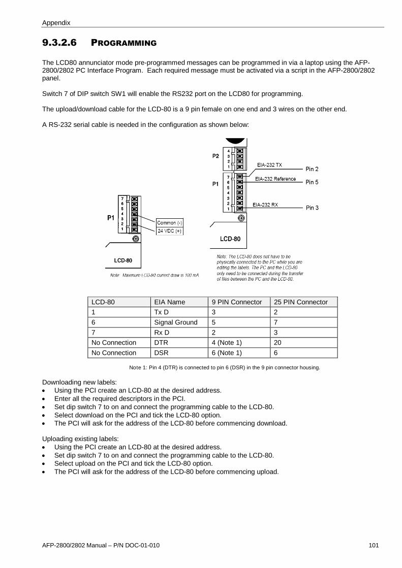
Appendix
AFP-2800/2802 Manual – P/N DOC-01-010 101
9.3.2.6 PROGRAMMING
The LCD80 annunciator mode pre-programmed messages can be programmed in via a laptop using the AFP-2800/2802 PC Interface Program. Each required message must be activated via a script in the AFP-2800/2802panel.
Switch 7 of DIP switch SW1 will enable the RS232 port on the LCD80 for programming.
The upload/download cable for the LCD-80 is a 9 pin female on one end and 3 wires on the other end.
A RS-232 serial cable is needed in the configuration as shown below:
LCD-80 EIA Name 9 PIN Connector 25 PIN Connector
1 Tx D 3 2
6 Signal Ground 5 7
7 Rx D 2 3
No Connection DTR 4 (Note 1) 20
No Connection DSR 6 (Note 1) 6
Note 1: Pin 4 (DTR) is connected to pin 6 (DSR) in the 9 pin connector housing.
Downloading new labels: Using the PCI create an LCD-80 at the desired address. Enter all the required descriptors in the PCI. Set dip switch 7 to on and connect the programming cable to the LCD-80. Select download on the PCI and tick the LCD-80 option. The PCI will ask for the address of the LCD-80 before commencing download.
Uploading existing labels: Using the PCI create an LCD-80 at the desired address. Set dip switch 7 to on and connect the programming cable to the LCD-80. Select upload on the PCI and tick the LCD-80 option. The PCI will ask for the address of the LCD-80 before commencing upload.

Appendix
AFP-2800/2802 Manual – P/N DOC-01-010 102
9.4 RECOMMENDED CABLING REQUIREMENTS
99..44..11 RRSS--448855 RRIINNGG CCOOMMMMUUNNIICCAATTIIOONN CCAABBLLIINNGG
Applies to: Ring 1 communication lines Annunciator communication lines
Requirements:
Style Minimum 0.75mm2
x 2 core Twisted Pair Shielded communications cable(+ separate 2 core cable for 24VDC module power )
Max distance Communications cable: 1000M between modules with 1.5mm2
cable(24VDC power cable distance will be determined by voltage drop)
Notes: Maximum of 16 annunciators between any two modules Fire rated cables may be required as per AS1670, AS1668, AS2118
Note: When annunciators or Field Modules are powered from external power supplies, use a separate conductor toconnect the main power supply common terminal (-0V) to the remote power supplies common terminal (-0V).
The EIA-485 circuit MUST be wired using a twisted-pair shielded cable. Do not run cable adjacent to, or in thesame conduit as, 240-volt AC service, noisy electrical circuits that are powering mechanical bells or horns, audiocircuits above 25 VRMS or motor control circuits. All enclosures, including the FIP cabinet, must be connected toelectrical earth! Never use the shield as an earthing conductor.
Terminate the shield at the outside of the FIP cabinet (ground). Where this is not possible, the shield must beterminated to physical ground immediately adjacent to cable entry. Between Field modules, connect shieldstogether outside of their respective enclosures. Make sure that the shield is only grounded at the FIP and not atthe modules or annunciators. Do not ground both ends of the shield; one end should be left floating.
FIP Cabinet
Shield
Data Cable
Terminate theshield at theoutside of the FIPcabinet (ground).
Do not ground bothends of the shield;one end should beleft floating.
Do not connectshields to modules orannunciators.Wire shields togetheroutside of therespectiveenclosures.
FIM

Appendix
AFP-2800/2802 Manual – P/N DOC-01-010 103
99..44..22 AADDDDRREESSSSAABBLLEE LLOOOOPP CCAABBLLIINNGG
Applies to:
Signalling Line Circuit (SLC) loops. Refer to the SLC Wiring Manual for more detailed specifications andspecific device listings.
Requirements:
RecommendedCable
TWISTED pair, NOT shielded. The cable should have short overall twist lengths (8 ormore twists per metre).
Max distance Recommended cable type (unshielded): *3810 m using 3.25 mm
2Twisted-unshielded pair
*3000 m using 2.5 mm2Twisted-unshielded pair
*2000 m using 1.5 mm2Twisted-unshielded pair
*1000 m using 0.75 mm2Twisted-unshielded pair
Others: 1000 m using 0.75 mm
2, 1500 m using 1.5 to 3.25 mm
2Twisted-shielded pair
1000 m using 0.75 mm2, 1500 m using 1.5 to 3.25 mm
2Untwisted-unshielded cable
MaximumCurrent
130 mA: LCM-320 100 mA: LEM-320 400 mA max**: Single SLC loop
Maximumresistance
Maximum 50 ohms (supervised and power-limited).
For more information on installation checks, refer to section 9.6.4.2 Analog Loop Installationchecks and fault finding
MaximumCapacitance
Maximum total capacitance for all SLC wiring (both between conductors and from anyconductor to ground) should not exceed 0.5 microfarads
Notes: Usage of shielded or flat cable for the SLC loops is not recommended and should beavoided where possible.
Fire rated cables may be required as per AS1670, AS1668, and AS2118. Separate 2 core cable to be run for 24VDC power to FZM-1 and FCM-1 modules
*Max distance of the loop is governed by the total loop resistance and will depend on the type of cable used.Always check the cable specification to ensure the total loop resistance will be less than 50 ohms for the requiredlength of cable. A higher resistance than 50 ohms will result in communication problems on the addressable loop.**Max short circuit…circuit will shut down until short circuit condition is corrected.
Floating Shield
Twisted-unshielded wire is recommended. If twisted-shielded pair wire is installed, use a floating shield toterminate the wire. The following precautions must be met:
• If the SLC is more than 900 m, divide the shield into floating segments of less than 300 m.• To divide the shield wire into floating segments, cut shield even with jacket and tape as shown:
NOTE: Using shielded wire in applications where it is not recommended will reduce the maximum SLC length. Ifshielded wire must be used where not recommended, failing to float the ends will reduce the maximum SLClength even further.

Appendix
AFP-2800/2802 Manual – P/N DOC-01-010 104
99..44..33 NNOOTTII..FFIIRREE..NNEETT NNEETTWWOORRKK CCAABBLLIINNGG
Wire Circuits
Applies to:
AFP-2800 networks using NCM-W network cards and RPT-W repeaters.
Requirements:
RecommendedCable
0.75 mm2
x 2 core TWISTED pair, NOT Shielded The cable should have short overalltwist lengths (8 or more twists per metre).
Max distance Recommended cable type (unshielded): 900 m between each segment (node) using 0.75 mm
2Twisted-unshielded pair. A
repeater module (RPT-W) can be used to increase this distance between nodes.
Other: 350 m between each segment (node) using 3.25 mm
2Twisted-shielded pair.
Maximumresistance
Wire length resistance for each cable segment cannot exceed 15 ohms.
Notes Refer to NOTI.FIRE.NET manual for detailed cabling requirements and selection of thresholdsettings for NCM-W cards.
Refer to High-Speed NOTI.FIRE.NET manual for detailed cabling requirements for the highspeed range of devices such as HS-NCM.
Fibre Optic Circuits
Applies to:
AFP-2800 networks using NCM-F network cards and RPT-F repeaters.
Requirements:
The attenuation of cabling between two nodes/repeaters (fibre optic circuits are point-to-point) is limited by cablechoice. If the distance required for a circuit segment is greater than permitted, a Repeater module (RPT-F) mustbe inserted into the circuit at intervals less than, or equal to, the attenuation length restriction.
Multi-mode fibre:
62.5/125μm cable - 8dB limit 50/125μm cable - 4.2dB limit
Single-mode fibre:
9/125μm cable - 8dB limit
The actual attenuation can be measured end-to-end with fibre-optic industry standard equipment using a testwavelength of 850 nanometres for multi-mode and 1310 nm for single-mode.
For a quick approximation, perform the following calculations:
a. Calculate loss due to cable. Look up the rated dB loss per foot within the cable manufacturer's specifications.Multiply this by the length of cable between the two nodes/repeaters to determine loss due to cable:Loss = (loss/ft.) x (length in feet).b. Calculate loss due to connectors/splices. Look up the dB loss for each connector and splice, and add allfigures to determine loss due to connectors/splices.c. Calculate total loss. Add the attenuation factors obtained in steps a. and b. This will provide an approximateattenuation total.

Appendix
AFP-2800/2802 Manual – P/N DOC-01-010 105
9.5 INTELLIGENT SENSING FEATURES
99..55..11 FFLLAASSHHSSCCAANN DDEETTEECCTTOORR LLEEDD OOPPEERRAATTIIOONN
The detector LEDs will blink green every 6 seconds under normal conditions. When in fault, an intelligentaddressable device will blink its address id to simplify locating the faulty device.
Blink pattern examples for faulty devices are given below.
Address Blink Pattern
8 8 blinks, long stop, 8 blinks, long stop, …
37 3 blinks, stop, 7 blinks, long stop, 3 blinks, stop, 7 blinks, long stop, …
152 15 blinks, stop, 2 blinks, long stop, 15 blinks, stop, 2 blinks, long stop, …
99..55..22 DDEETTEECCTTOORR IINNIITTIIAALLIISSAATTIIOONN
The control panel automatically performs a detector initialisation routine when a detector is added or changed.The detector initialisation routine takes approximately 2.5 minutes. During this time, the detector being initialiseddoes not perform fire protection functions. The LEDs of detectors polled in FlashScan mode will latch a steadygreen while initialising, and return to blinking green when initialisation is over.
While initialising a detector, follow these guidelines:
• Make sure the detector is free of residual smoke during detector initialisation.• Do not test a detector during detector initialisation.
NOTE: The control panel only performs detector initialisation if it senses that a detector was removed forat least 15 seconds.
WARNING!!If any detector is replaced with a different type of detector (for example, a laser detector is replaced with aphotoelectric detector), the control panel must be programmed immediately with the new detector Type Code.Failure to do so can cause incorrect control panel operation, including false alarms.
99..55..33 SSEELLFF--OOPPTTIIMMIIZZIINNGG PPRREE--AALLAARRMM
A Self-Optimizing Pre-Alarm can set each detector, except FST-851/751 (Heat), by programming the detector tohave a Pre-Alarm sensitivity level setting of 1. In Self-optimizing mode, the software measures the normal peakAnalog readings and sets the Pre-Alarm level just above these normal peaks. This allows extremely sensitive Pre-Alarm capability with reasonable protection against non-fire signals. The figure below shows a graphicalrepresentation of the Self-Optimizing Pre-Alarm level:
99..55..44 DDEETTEECCTTOORR SSEENNSSIITTIIVVIITTYY
The control panel provides nine Sensitivity Levels for alarm detection and pre-alarm as follows:

Appendix
AFP-2800/2802 Manual – P/N DOC-01-010 106
• Alarm Sensitivity Levels You can select the sensitivity of a detector from 1 to 9 (1=highest sensitivity; 9=lowestsensitivity).• Pre-Alarm Sensitivity Levels You can select one of nine levels from 1 to 9 (1=self-optimizing, 2=highestsensitivity, 9=lowest sensitivity).
You can set the sensitivity levels as fixed or programmed for day and night operation.
Analog Addressable Detectors Sensitivity Settings Table
Detector TypeAlarm
%/Metre ObscurationPre-Alarm
%/Metre Obscuration
Photo Optical Level 1 0.50% Auto
Level 2 2.40% 0.98%
Level 3 3.15% 1.54%
Level 4 3.90% 2.10%
Level 5 4.69% 2.66%
Level 6 5.45% 3.25%
Level 7 6.20% 3.81%
Default Level 8 6.96% 4.36%
Level 9 7.71% 4.92%
Ionisation Level 1 1.64% Auto
Level 2 2.46% 1.31%
Level 3 3.28% 1.64%
Level 4 4.10% 2.46%
Level 5 4.92% 3.28%
Level 6 5.74% 4.10%
Level 7 6.56% 4.92%
Default Level 8 7.38% 5.74%
Level 9 8.20% 6.56%
Laser (View) Level 1 0.07% Auto
Level 2 0.10% 0.07%
Level 3 0.16% 0.16%
Level 4 0.33% 0.33%
Level 5 0.66% 0.66%
Level 6 1.64% 1.64%
Level 7 3.28% 2.30%
Default Level 8 4.92% 3.28%
Level 9 6.56% 4.92%
Alarm (CLIP)
Acclimate Level 1 1.64% 3.28% Auto
Level 2 3.28% 3.28% 3.28%
Level 3 3.28 to 6.56% 3.28 to 6.56% 3.28%
Level 4 6.56% 6.56% 3.28 to 6.56%
Level 5 6.56 - 9.84% 6.56 to 13.12% 3.28 to 6.56%
Level 6 9.84% 6.56 to 13.12% 6.56%
Level 7 9.84 - 13.12% 6.56 to 13.12% 6.56%
Default Level 8 13.12% 13.12% 6.56 - 9.84%
Level 9 63OC degrees Heat Only 63
OC degrees 6.56 - 9.84%

Appendix
AFP-2800/2802 Manual – P/N DOC-01-010 107
Analog Addressable Detectors Sensitivity Settings Table
Detector TypeAlarm
Total ObscurationPre-Alarm
Total Obscuration
Beam Level 1 25% 50%
Level 2 30% 55%
Default Level 3 40% 60%
Level 4 50% 65%
Level 5 30 - 40% Auto 70%
Level 6 40 - 50% Auto 75%
Level 7 - 80%
Level 8 - 85%
Level 9 - 90%
Thermal Degrees Celsius Degrees Celsius
Level 1 43OC 40
OC
Level 2 57OC 43
OC
Default Level 3 63OC 57
OC
Level 4 68OC 65
OC
Level 5 74OC 70
OC
Level 6 90OC 75
OC
9.5.4.1 SMART4 & INTELLIQUAD SENSITIVITY AND APPLICATION GUIDE
SDX-751CTEM (Smart 4)
Smart 4 is a CLIP only Multi-Criteria detector that is programmed as an “Acclimate” detector to allow backwardcompatibility with older versions of software. Six different sensitivity settings are available with this detector.
The sensitivity settings and suggested applications for each setting are listed in the following table.
Sensitivity Suggested Application Details
Level 1 Ultra clean environments -Laboratories
3.28% per metre of smoke or greater than 45 ppm of CO.No delays from processed photo output
Level 2, 3 Clean environments – Offices 6.56% per metre of smoke. No delays from processedphoto output
Level 4 Moderately clean environments –Hotel/Dorm rooms
9.84% per metre of smoke. No delays from processedphoto output
Level 5, 6 Moderate environments – hotel nearshower, boiler rooms
9.84% per metre of smoke. Maximum of 10 minutes delayfrom processed photo output. See notes.
Level 7, 8Default
Harsh environments – Equipmentrooms, kitchens, night clubs
13.12% per metre of smoke. Maximum of 10 minutesdelay from processed photo output. See notes.
Level 9 Harsh environments Heat only alarm. If the heat level on either thermistorexceeds 63°C or rate of rise limits.
Notes: - The delay counter starts when the smoke level exceeds approximately 2.46% per metre. Maximum of 10minutes delay from processed photo output. If there is a detection of another fire signature (CarbonMonoxide, Infrared or Thermal) the detector overrides the 10 minute confirmation time.- Use of AVF function is not permitted by AS1670.1 at sensitivity levels 5, 6, 7, 8 and 9.- Smart 4 is a CLIP only detector and should be programmed as an “Acclimate”.- Level 9 may be used with day/night settings to provide heat only detection during certain times of the day.
FSC-851 (IntelliQuad)
IntelliQuad detector is a FlashScan Multi-Criteria detector which will also run in CLIP mode. When in FlashScanmode, the CO and temperature levels can be accessed through the read status menu on the panel.

Appendix
AFP-2800/2802 Manual – P/N DOC-01-010 108
The sensitivity settings and suggested applications for each setting are listed in the following table.
Sensitivity Suggested Application Details
Level 1 Ultra Clean environments -Laboratories
3.28% per metre of smoke or greater than 45 ppm of CO.No delays from processed photo output.
Level 2 Clean environments - Offices 6.56% per metre of smoke. No delays from processedphoto output
Level 3Default
Moderately clean environments –Hotel/Dorm rooms
9.84% per metre of smoke. No delays from processedphoto output.
Level 4 Moderate environments – hotel nearshower, boiler rooms
9.84% per metre of smoke. Maximum of 10 minutes delayfrom processed photo output. See notes.
Level 5 Harsh environments – Equipmentrooms, kitchens, night clubs
13.12% per metre of smoke. Maximum of 10 minutes delayfrom processed photo output. See notes.
Level 6 Harsh environments Heat only alarm. If the heat level on either thermistorexceeds 60°C or rate of rise limits.
Notes: - The delay counter starts when the smoke level exceeds approximately 2.46% per metre. Maximum of 10minutes delay from processed photo output. If there is a detection of another fire signature (CarbonMonoxide, Infrared or Thermal) the detector overrides the 10 minute confirmation time.- Use of AVF function is not permitted by AS1670.1 at sensitivity levels 4, 5 and 6.- Level 6 may be used with day/night settings to provide heat only detection during certain times of the day.
99..55..55 DDRRIIFFTT CCOOMMPPEENNSSAATTIIOONN
Drift compensation uses algorithms that identify and compensate for long term changes in the Analog readingsfrom each smoke detector. (Typically, dirt and dust accumulation inside the smoke chamber causes long-termchanges in detector readings.) Drift compensation does the following:
• Allows a detector to retain its original ability to detect actual smoke, and resist false alarms, even as dirtand dust accumulates.• Reduces maintenance requirements by allowing the control panel to automatically perform the periodicsensitivity measurements.
The software also provides smoothing filters to remove transient noise signals, usually caused by electricalinterference. Different smoothing algorithms are used, depending on the sensitivity selection of each detector.
The software determines when the drift compensation for a detector reaches an unacceptable level that cancompromise detector performance. When a detector reaches an unacceptable level, the control panel indicates amaintenance warning. The table below summarizes the three levels of Intelligent Sensing maintenance warnings:
Detector FaultMessage
Indicates Detector Compensation PercentageRange
Ion Photo Laser AcclimateSmart 4IntelliQuad
N/A Compensation is within recommended range. 6 - 91 6 - 91 3 - 82 0 - 79
LOW THRESHOLD A hardware problem in the detector. 0 - 5 0 - 5 0 - 2 N/A
MAINTENANCEREQ
Dust accumulation that is near but below theallowed limit. The Maintenance Required is analert level that indicates the need formaintenance before the performance of thedetector is compromised.
92 - 99 92 - 99 83 - 99 80-99
MAINT.URGENT Dust accumulation above the allowed limit. 100 100 100 100
A drift compensation value above the recommended range indicates that the detector should be cleaned foroptimum performance. Note that the drift compensation values for Acclimate and IntelliQuad detectors can onlybe accessed through the read status menu if the loop in running in FlashScan mode. The drift compensationvalue for a multi criteria detector is not available in CLIP mode.

Appendix
AFP-2800/2802 Manual – P/N DOC-01-010 109
99..55..66 FFAAUULLTT CCOODDEESS
These codes apply to Analog devices and are added to the history log as well as being displayed in the Fault Listwhen the fault occurs.
Actual Fault CodeDisplayed
Possible causes
No Response FAULT (F01) The device in fault is not communicating with the LCM. This fault canoccur if the device is not physically connected, damaged or set at wrongaddress.
MismatchedHardware Type
FAULT (F02) The actual device type is different to the programmed type. This faultwould occur if an incorrect device type is used such as a heat detectorinstead of a photo optical detector.
Devices At SameAddress
FAULT (F03) Two devices have the same address on the loop.
Incorrect Response FAULT (F04) The device has returned an incorrect response. This fault can occur ifthe device is faulty or the loop wiring is substandard. If the resistance ofthe entire loop wire exceeds 50 ohms, this fault will be observedintermittently.
Open Circuit FAULT (F05) An Analog module does not have the End Of Line resistor connected oran incorrect value of EOL is used.
Short Circuit FAULT (F06) There is a short circuit on the output terminals of an Analog relaymodule.
Low Threshold FAULT (F07) A low threshold fault indicates a faulty detector which needs to bereplaced.
Maintenance Alert FAULT (F08) Analog detector needs cleaning.
Maintenance Urgent FAULT (F09) Analog detector needs cleaning urgently. Once the detector is inmaintenance urgent fault it will no longer provide reliable detection offire.
Verify Count Over 20 FAULT (F010) Not used on AFP-2800/2802.
Detector Failed Test FAULT (F011) LCM performs a test on each detector every 2 – 3 hours. This fault canoccur if the device is faulty or the loop wiring is substandard. If theresistance of the entire loop wire exceeds 50 ohms, this fault will beobserved intermittently.
Security Tamper FAULT (F012) Not used on AFP-2800/2802.
Low Temperature FAULT (F013) Not used on AFP-2800/2802.
Ground Fault FAULT (F014) Less than 50kohms resistance to ground. The Ground Fault LED on theaffected LCM will be ON (refer to page 117).
Charger Fault FAULT (F015) Not used on AFP-2800/2802.
Battery Low FAULT (F016) Not used on AFP-2800/2802.
Battery High FAULT (F017) Not used on AFP-2800/2802.
General Trouble FAULT (F018) General fault code that LCM uses when it can not detect the actualproblem with the device. This fault can occur if the device is faulty or theloop wiring is substandard. If the resistance of the entire loop wireexceeds 50 ohms, this fault will be observed intermittently.
Missing Address FAULT (F019) Not used on AFP-2800/2802.
AC Fail FAULT (F020) Not used on AFP-2800/2802.
Module ExternalPower Loss
FAULT (F021) 24 volt power is not connected to the Analog module. (ConventionalZone and Control modules).
Wrong OEM DeviceType
FAULT (F022) The device on the loop is using the wrong communication protocol.Replace the device with a version that has compatible protocol with thepanel.
RFX CommunicationLoss
FAULT (F023) Not used on AFP-2800/2802.

Appendix
AFP-2800/2802 Manual – P/N DOC-01-010 110
Actual Fault CodeDisplayed
Possible causes
Beam Blocked FAULT (F024) Beam Detector Fault - Something has come between the detector’sbeam and its reflector.
Alignment Mode FAULT (F025) Beam Detector Fault - A beam detector is in configuration mode.
Device Disabled FAULT (F026) Not used on AFP-2800/2802.
Zone Disabled FAULT (F027) Not used on AFP-2800/2802.
Initialisation Mode FAULT (F028) Beam Detector Fault - A beam detector is running through itsinitialization sequence.
Incorrect Position FAULT (F029) Beam Detector Fault -
Over Range FAULT (F030) Not used on AFP-2800/2802 - FMM-4-20.
Under Range FAULT (F031) Not used on AFP-2800/2802 - FMM-4-20.
Device Inhibit FAULT (F032) Not used on AFP-2800/2802 - FMM-4-20.
No ThresholdProgrammed
FAULT (F033) Not used on AFP-2800/2802 - FMM-4-20.
Trouble 1 FAULT (F034) Not used on AFP-2800/2802 - FMM-4-20.
Trouble 2 FAULT (F035) Not used on AFP-2800/2802 - FMM-4-20.
Comms Loss FAULT (F036) Not used on AFP-2800/2802 - FMM-4-20.
Command Failed FAULT (F037) Not used on AFP-2800/2802.
Thermistor Fault FAULT (F038) The thermistors are not functioning properly on a FSC-851 detector.This trouble is generated for FlashScan mode only.
IR Fault FAULT (F039) The infrared element is not working properly on a FSC-851 detector.This trouble is generated for FlashScan mode only.
IR Light Saturation FAULT (F040) The infrared sensor on a FSC-851 detector is saturated.
CO 6 Month Of Life FAULT (F041) The CO (carbon monoxide) detection element on a FSC-851 detectorhas six months left to expiration.
CO Life Expired FAULT (F042) The CO (carbon monoxide) detection element on a FSC-851 detectorhas expired.
CO Fault FAULT (F043) The CO element on a FSC-851 detector is not working properly. Thistrouble is generated for FlashScan mode only.

Appendix
AFP-2800/2802 Manual – P/N DOC-01-010 111
9.6 PANEL CONNECTION DIAGRAMS:
99..66..11 MMAAIINN TTEERRMMIINNAATTIIOONN BBOOAARRDD ((FFIIMM))
Data Connectorto processorboard
Ring powerconnector
Ring Dataconnector
Heartbeat LED RelayIndicatorLEDs
Ring &Earth faultstatus LEDs
Local relay O/Pconnector withfused
Power Status & controlfrom power supply
Main 24VPower Input
Two 24V/1AOutput
RelayExpansionConnector IN
Local AZConnector
Programming connectorto Black box
Serial I/Oconnector toCPU board
Power andComm toAnnunciatorboard
Expansion toLIM/NIMBoard
RelayExpansionConnector OUT
Local relayO/Pconnector
Processor Resetbutton Ring & Earth
Fault Status LED
SC AShort Circuit on Ring1 power A
SC BShort Circuit on Ring1 power B
EFLTEarth fault detectedon panel or powersupply
Open –Ring 1 data negativeleg is open circuit.
Open +Ring 1 data positiveleg is open circuit.
CONNECTING RIBBONS TO CPU
FR
OM
CP
UM
OD
UL
E
40 WAYRIBBONCABLE
FR
OM
CP
UM
OD
UL
E
20 WAYRIBBONCABLE
J1

Appendix
AFP-2800/2802 Manual – P/N DOC-01-010 112
9.6.1.1 POWER SUPPLY CONNECTIONS - PS243 & PS249
IFS-704/714/724 TERMINATION BOARD
TERM 2
Ba
tLo
w
Sy
sFa
il
0V
BT
est
MF
ail
VB
att
24
VIn
pu
t
0V
Inp
ut
9.6.1.2 POWER SUPPLY CONNECTIONS - NPS-2/5/11The following settings are used when connecting a NPS power supply to an IFS-724 FIM using the ribbon cable:
1. The CPU must have V5.02 or above firmware installed.2. Set the bottom dipswitch on mode dipswitch U25 (on the back of the CPU) to the on position. Note that the
dipswitch can be marked 1 or 4. Always set the dipswitch closest to the upload/download port.3. J6 on IFS-724 FIM board must be fitted.
NI-2012Power SupplyInterface (PSI)
IFS-724 FIMTermination Board
NI-2012 (PSI) Dipswitch Settings:Normal operation: All offNZ Operation: 1 on, all others offManual mode: 2 on, all others off
Fit Link at J6
Refer to PowerSupply Interface(PSI) Manual formore information

Appendix
AFP-2800/2802 Manual – P/N DOC-01-010 113
9.6.1.3 MAIN TERMINATION BOARD – CONNECTING RS485
+IN
-IN
SHIELD
+OUT
-OUT
SHIELD
COMMS CABLE TO FIRST MODULE
COMMS CABLE FROM LAST MODULE
-
+
-
+
TERM 4
SOCKET PLUG
TERM 6
Co
mm
sA
Co
mm
sB
Note: Terminate the shield at the outside of the FIP cabinet (ground). Where this is not possible, the shield must beterminated to physical ground immediately adjacent to cable entry. Between Field modules, connect shieldstogether outside of their respective enclosures. Make sure that the shield is only grounded at the FIP and notat the modules or annunciators. Do not ground both ends of the shield; one end should be left floating.
9.6.1.4 MAIN TERMINATION BOARD – CONNECTING 24VDC
+AZ1
-AZ1
+AZ2
-AZ2
TERMINATION BOARD
PWR A(+)
PWR A(-)
PWR B(+)
PWR B(-)
TO FIRSTMODULE IN
LOOP
FROM LASTMODULE IN
LOOP
+ 24V - 24V
+ 24V- 24V
PLUGSOCKET
9.6.1.5 MAIN TERMINATION BOARD – CONNECTING AZF’S 1 & 2
+AZ1
-AZ1
+AZ2
-AZ2
TERMINATION BOARD
ALARM ZONE INPUT
UNUSED INPUT
4700 Ohms

Appendix
AFP-2800/2802 Manual – P/N DOC-01-010 114
9.6.1.6 MAIN TERMINATION BOARD – CONNECTING RELAY OUTPUTS
4 x Clean Contact Relays 4 x Monitored 24V Outputs (4k7 EOL Resistors)
+AZ1
-AZ1
+AZ2
-AZ2
T ERM IN ATION B O ARD
+P OW A
-POW A
+P OW B
-POW B
TER M 4
TER M 2
C ommsT erminal
-COM A
+CO M A
-COM B
+CO M B
NO
CM
N C
NO
CM
NC
NO
CM
N C
N O
C M
N C
TE RM 5
+PR3
-
+PR4
-
TER M 1
+BELL
-
+W /SYS
-
NO
CM
NC
NO
CM
NC
NO
CM
NC
NO
CM
N C
TERM 5
9.6.1.7 MAIN TERMINATION BOARD – PANEL EXPANSION RELAYS
TERMINATION BOARD
J16 J17
OUT IN
Note that the panel expansion relay boards must be connected in a closed serial loop betweenJ16 and J14 on the Main Termination Board for the software to auto-detect the actual number ofRelay boards connected. The maximum allowed is 8 x 8 way relay boards. If the serial loop is leftopen, the panel will assume that all 8 boards are present.
Note: If no expansion relay boards are used, jumper pins J18, situated close to the J14 connector,must be shorted together.

Appendix
AFP-2800/2802 Manual – P/N DOC-01-010 115
99..66..22 CCPPUU
Panel LEDconnector
Panel buttonconnector
LCD contrast adjust
IBM PS/2 Keyboard Connector
Serial PrinterPort
Upload/DownloadSerial Port to PC
5V PowerConnector
Restart Switch
Data Connector toTermination Board
Serial I/O connectorto Termination
Board
Test pointsScript Running LEDs
LCD BacklightPlug
Option Switch
Keyboard EnableJumper
PS/2KeyboardConnector
9.6.2.1 UPLOAD/DOWNLOAD PORT SETTINGS
Port Information Connector InformationMode RS232 Type DB9 FemaleBaud Rate 115200 Location CPU Conn 2Data Bits 8 TX Pin 3Stop Bits 1 RX Pin 2Parity None GND Pin 5Handshaking None
Cable Specification AFP-2800/2802 End (CONN2) Laptop EndDB9 Male DB9
Female2 (RX) 2 (RX)
3 (TX) 3 (TX)
5 (REF) 5 (REF)
8 (CTS) 7 (RTS)
9.6.2.2 PRINTER PORT SETTINGS
Caution: The PS/2 keyboard and serial printer must not be connected at the same time or printing errors will result.The serial printer (where fitted) must be disconnected whilst the keyboard is plugged in.
Port Information Connector InformationMode RS232 Type DB9 FemaleBaud Rate 9600 Location CPU Conn 1Data Bits 8 RX Pin 2Stop Bits 1 GND Pin 5Parity Odd CTS Pin 8Handshaking Hardware
Cable Specification AFP-2800/2802 End (CONN1) Printer End (25 or 9 pin)DB9 Male DB25
MaleDB9 Male
3 (TX) 3 (RX) 2 (RX)
5 (REF) 7 (REF) 5 (REF)
8 (CTS) 4 (RTS) 7 (RTS)
Note: If using a DPU414 thermal printer with 9 pin connector, connect pins 3, 5, 8 on AFP-2800/2802 to pins 3, 5,8 on the printer (1 to 1). Refer to printer manual for detailed connection information.

Appendix
AFP-2800/2802 Manual – P/N DOC-01-010 116
99..66..33 LLOOOOPP IINNTTEERRFFAACCEE MMOODDUULLEE ((LLIIMM))
To Network Interface Module ORLoop Interface Module if no NIM
exists
40 WAYRIBBONCABLE
MAIN TERMINATION BOARD (FIM)
J3
Not used on LIM
Ribbon cable from FIM orNIM (if fitted)
Power connectorfrom FIM
Not used on LIM
Not used on LIM
20 way ribbon cableto LCM/LEM boards
Factory Programming Port
Reset Switch
Address Switch
Address Settings:
Description SW1 SW2 SW3 SW4Loop Interface Module (For use with LCM’s) OFF ON OFF OFFNetwork Interface Module (For use with NCM’s) ON ON OFF OFF

Appendix
AFP-2800/2802 Manual – P/N DOC-01-010 117
99..66..44 AANNAALLOOGG LLCCMM AANNDD LLEEMM TTEERRMMIINNAATTIIOONNSS
The LCM-320 and the updated ELCM-320 is a 1-loop board that can support up to 159 detectors and 159modules in FlashScan mode or 99 detectors and 99 modules in CLIP mode. The field wiring is electrically isolatedfrom the rest of the system so that any two-ground faults on separate loops will not cause invalid replies fromdevices. A short to any other system circuit will not cause communication loss. The LCM has an earth faultdetection circuit with a yellow LED displaying an earth fault condition. ELCM modules also include a greenheartbeat LED to show that the processor is working.
The LEM is an expansion board that attaches to its LCM parent providing a second loop which has the samefeatures as the parent loop.
MicroController
Connector to LEM
Ground Fault on LCM
20 Way Ribbon tonext LCM
20 Way Ribbon FromLIM or Previous LCM
Address Switch
Ground Fault on LEM
LCM Firmware5VDC OK
First Loop(Loops 1, 3, 5, 7, 9)
Second Loop(Loops 2, 4, 6, 8, 10)
Heartbeat LED (ELCM)
Loop Connections Address Switch Settings
A-
B-
A+
B+
Inserting a pair of LCM/LEM into CHS-3L/4L

Appendix
AFP-2800/2802 Manual – P/N DOC-01-010 118
Connecting LCM with LEM
9.6.4.1 LOOP WIRING STYLES:
Loops may be operated one of several modes – style 4, style 6 as well as style 7 (refer to diagrams below). Style4 is an open loop arrangement while styles 6 and 7 are closed loop arrangements. Refer to section 0 for loopconfiguration details and to section 9.4.2 for cabling requirements.
Style 4. (Open loop – does not return to the panel, non-redundant)Port A (Channel A) 3810m maximum, 50 Ω s resistance maximum. Port B (Channel B) 3810m maximum, 50 Ω resistance maximum. In style 4, the processor will poll both legs of the “loop” simultaneously through its own driver. If either leg isshorted (wire-wire), the other leg is not degraded since it is operated from a separate driver.
Style 6. (Closed loop – returns to panel providing a redundant path for open circuit conditions)Total Loop, 3810m maximum, 50 Ω resistance maximum. In style 6, the processor polls the loop from one of the drivers (the B-side). If a failure (open circuit) is detected, itwill poll through both ends.
Style 7. (Closed loop with isolation modules providing a redundant path for short circuit conditions)Total Loop, 3810m maximum, 50 Ω resistance maximum. Maximum of 25 devices between isolation modules (Note: contact Notifier more details)In style 7, the processor polls the loop from one of the drivers (the B-side). If a failure (short circuit) occursbetween two isolation modules or the A or B ports of the LCM and an isolation module, the shorted section of loopwill be isolated and the processor will poll through both ends. Note that the A and B ports of the LCM also provideshort circuit isolation.

Appendix
AFP-2800/2802 Manual – P/N DOC-01-010 119
Two wire addressable detector
Addressable moduleBranch A
Branch B
A+A-B-B+ To LCM or LEMSTYLE 4
Two wire addressable detector
Addressable moduleLoop Out
Loop Return
A+A-B-B+ To LCM or LEM
STYLE 6
Two wire addressable detector
Addressable module
Loop Out
Loop Return
A+A-B-B+ To LCM or LEM
ISO-X
ISO-X
Isolation module
STYLE 7

Appendix
AFP-2800/2802 Manual – P/N DOC-01-010 120
9.6.4.2 ANALOG LOOP INSTALLATION CHECKS AND FAULT FINDING
Before connecting a loop to an LCM or LEM card, carry out the following tests:
1. Check loop continuity and resistance by placing a short circuit on one end of the loop and reading the loopresistance with a multimeter at the other (be sure to set the multimeter to Ohms). The loop resistance cannotexceed 50 Ohms which is 25 Ω per leg. Refer to note below if using loop isolator devices.
2. Check devices for correct wiring as follows. With both ends of the circuit open, set the multimeter to diodetest, and place the leads on the cable, the reading should be approx. 0.645, reverse the leads to get a readingof approximately 1.2 or higher. If both readings are low, there is an incorrectly wired device, or a short on thewiring. (Note: Each device has a diode installed)
3. Check the loop voltage as follows. Set the multimeter to D.C. volts and read the voltage at the loop cardbefore connecting the loop. The reading should be approximately 23 - 25 volts with no devices programmedon the loop. If there are devices programmed on the loop then the voltage will be approximately 13 - 16 volts.Now connect the loop. The reading should be the same as when the loop was disconnected. If the measuredvoltage is below the specified values, there could either be a short on the line or a device may be incorrectlywired (possible reverse polarity). Find the device and correct the loop connections at that device.
4. Check that there are no earth faults as follows. Select ohms on the multimeter and measure between each legof the loop and earth. If the reading falls below 50,000 Ω, an earth fault will be indicated when the loop is connected. Find the cause of the earth fault and rectify it. (Note: Possible causes of an earth fault aremoisture, inadequate insulation from the surrounding building, equipment or materials).
NOTE:Loop resistance measurement when isolation modules or bases are present:
ISO-X ModulesWhen power is removed from the loop, the positive side of the circuit is opened at each isolationmodule. To measure the loop resistance, temporarily place a jumper between terminals 2 and 4 oneach ISO-X while taking measurements. Remember to remove all the jumpers and test all isolatormodules when you have finished taking the readings.
B524IEFT-1 Isolator BaseWhen power is removed from the loop, the positive side of the circuit is opened at each isolatorbase. To measure the loop resistance, temporarily place a jumper between terminals 5 (A+) and 6(B+) on each B524IEFT-1 before taking measurements. Remember to remove all the jumpers andtest all isolator bases when you have finished taking the readings.
All addressable sounder/strobes with built in isolators should also be removed from the loopwhile taking measurements.
Refer to SLC Wiring Manual for more information.

Appendix
AFP-2800/2802 Manual – P/N DOC-01-010 121
99..66..55 NNOOTTII..FFIIRREE..NNEETT™™
Note: AFP-2802 does not support networking. The rest of this section only applies to the AFP-2800 FIP.
Noti.Fire.Net™ is a series of modules and products which allow a group of Fire Alarm Control Panels (FACP) andother control equipment to connect, forming a true peer-to-peer network. Equipment that connects to Noti.Fire.Net™and communicates with other equipment using the network may be referred to as a network node. The minimumhardware requirement for Noti.Fire.Net™ is two nodes connected via wire (or optical fibre). Noti.Fire.Net™ for theAFP-2800 supports up to 100 nodes. The AFP-2800 occupies a single node address on the network. Eachnetwork node requires a unique node address; the node communicates with other nodes via a Network ControlModule (NCM). The NCM connects to the AFP-2800 via the Network Interface Module (NIM).
9.6.5.1 NETWORK INTERFACE MODULE (NIM)
To Network Interface Module
40 WAYRIBBONCABLE
MAIN TERMINATION BOARD (FIM)
J3
Ribbon cable to LIM (If fitted)
Ribbon cable from FIM(termination board)
Power connectorfrom FIM (terminationboard)
NCM connection(NUP port on IFS-725)
Not used on NIM
20 Way ribbon cableto LCM/LEM boards
Factory programming port
Reset Switch
Address Switch
Address Settings SW1 SW2 SW3 SW4
Network Interface Module ON ON OFF OFF
NIM connects to the NUP port on the NCM.

Appendix
AFP-2800/2802 Manual – P/N DOC-01-010 122
NIM (IFS-725) to NCM cable specification:
Standard 5 way NUP cable connects J6 connector on IFS-725 NIM to NUP 1 (J3) connector on NCM.
NIM (IFS-705) to-NCM cable specification:
NIM end NCM endComm B NUP Port
RxTx (Pin 5)Ref (Pin 4)
0v Rx (Pin 3)
Tx0V (Pin 2)+24V (Pin 1)
+24V0V
Network connectionports (NUP)
NUP portconnectordetail
Pin 1
Pin 1
NUP 1
NUP 2

Appendix
AFP-2800/2802 Manual – P/N DOC-01-010 123
9.6.5.2 NOTI.FIRE.NET™ NCM SWITCHES & TERMINATIONS
Ground Faultdetection switches
and Network End OfLine TerminationResistor switches
Channel A & Bconnections
Network connectionports (NUP)
Diagnostic LEDs
Not used
B A AB
From last node,Port A
To next node,Port B
CONNECTIONDETAIL
Note:
Wiring from the NCM-W that is installed outside buildings:
- Must be in conduit and be buried in a trench separate from any power lines- Cannot cross any power lines
NCM-W Connections:
Connector Pin Signal NameTB100-1 CH-A (+) Channel-A Driver / ReceiverTB100-2 CH-A (-) Channel-A Driver / ReceiverTB100-3 CH-B (+) Channel-B Driver / ReceiverTB100-4 CH-B (-) Channel-B Driver / ReceiverTB100-5 Earth Ground

Appendix
AFP-2800/2802 Manual – P/N DOC-01-010 124
9.6.5.3 NCM SWITCH FUNCTIONS: GROUND FAULT DETECTION AND LINE
TERMINATION
The NCM-W provides two sets of switches to simplify network set-up. Default settings for AFP-2800 networks areshown in the diagram below.
EF B TE RM B EF A T ER M A
SW 100SW 101 SW 102 SW 103
O N
OF FOF F
ON SET UPSW IT CHDETAIL
To enable ground fault detection, set SW103 for Channel A; SW101 for Channel B, to the ON position To activate the on-board end-of-line resistors, set SW100 for Channel A; SW102 for Channel B, to the ON
position. There MUST be a functioning terminating resistor on the first and last node/repeater of a wiresegment (between 2 nodes). This means that in a ring configuration each NCM in the ring MUST haveterminating resistors enabled for both channels.
9.6.5.4 NCM DIAGNOSTIC LED INDICATORS:The NCM has LEDs that serve as diagnostic indicators to help in troubleshooting and system connection. Thetable below outlines their function.
A HI
RCD A
S TAT A
RE CO N
RE S ET
Diag nost icLE D detail
B HI
RC D B
S TAT B
P ULS E 1
P O WE R
LED Indicator LED Colour LED DescriptionA HI Green Illuminates to indicate that the NCM-W Port A is set for high thresholdB HI Green Illuminates to indicate that the NCM-W Port B is set for high thresholdRCD A Green Illuminates when the NCM is receiving data from the network on Port ARCD B Green Illuminates when the NCM is receiving data from the network on Port BSTAT A Yellow Illuminates when the NCM has not received valid data on Port A for at least
16 secondsSTAT B Yellow Illuminates when the NCM has not received valid data on Port B for at least
16 secondsRECON Yellow Illuminates when a reconfiguration on the network is in progressPULSE1 Green Illuminates when the NCM is transmitting data to the networkRESET Yellow Illuminates when the microcontroller failsPOWER Green Illuminates when +5VDC is available

Appendix
AFP-2800/2802 Manual – P/N DOC-01-010 125
9.7 MODEM/PRINTER/HLI INTERFACE
99..77..11 MMOODDEEMM IINNTTEERRFFAACCEE
The AFP-2800/2802 PC Interface can be used to control the FIP using a modem and AFP-2800/2802 PCIsoftware. A global option on the FIP will enable/disable modem operation.
9.7.1.1 PC MODEM
Any non software modem should work correctly with the PCI. It is recommended to use a high quality externalmodem to allow modifying of modem parameters to solve any possible compatibility issues.
9.7.1.2 FIP MODEM
The recommended modem for the FIP is a NetComm IG6000 (industrial modem) that is modified to work with24VDC. This modem was chosen due to its construction and reliability. NIFS part number is 10972.
9.7.1.3 FIP MODEM SETTINGS
The FIP modem needs to be programmed with the following AT commands using a terminal program such asHyperTerminal and the standard modem to PC cable provided:
Use “AT S0=2 R115 &K3 &S0 %E2” command to set the required modem options
ATS0=2 - answer after 2 ringsATR115 - lock terminal speed to 115000AT&K3 - RTS/CTS flow controlAT&S0 - DSR signal always assertedAT%E2 - Automatic speed stepping
To establish connection with the modem after the above commands have been entered, set HyperTerminal portsettings to 115 baud rate & RTS/CTS handshaking.
After re-connecting to the modem using the above settings, save the configuration to hardware profile 0 using theAT&W0 command.
Check modem configuration using AT&V command. Ensure that all the options are the same as the configurationprintout below:
B0 E1 L1 M1 T Q0 R115 V1 W2 X5 &B4 &C1 &D2 &G0 &H0 &K3 &L0 &M0 &N1 &P1 &R0 &S0&T4 &X0 &Y0 \A3 \B3 \J0 \K5 \N3 \T0 \V0 \X0 #A2 #B0 #C0 #D0 #E0 #F0 #I0 #J1#M0 #N0 #O0 #Q0 #U0 #V0 %B0 %C3 %D0 %E2 %F1 %G0 %H0 %K0 %L11 %M0 %N0 %P0 %R0%S0 %T0 %U0 %V0 %W0 *K0 *V0 *R0 *T0 *Y0 -Q1 :E1 -SDR0,1 #CID0 #MUS0S000:002 S002:043 S003:013 S004:010 S005:008 S006:004 S007:050 S008:004S009:006 S010:018 S011:095 S012:050 S018:000 S025:005 S026:000 S030:000S033:003 S042:002 S043:015 S045:098 S047:030 S066:010 S067:042 S069:060S076:080 S077:010 S105:030 S110:004 S126:061&Z0 = &Z1 =&Z2 = &Z3 =&Z4 = &Z5 =&Z6 = &Z7 =&Z8 = &Z9 =Last dialled = T2+MS: 12,1,300,56000,1,0Access Security: OFF Security Database, Security Mode & Call-Log Erase: FREEStored Phone Numbers: DISPLAYED OutDial: ENABLEDCaller ID: DISABLED DES: 64bitInternal Storage (#MEM): Enabled when DTR off: 4 Voice Messages#ALM1=0, #ALM2=0, PIN number =1234

Appendix
AFP-2800/2802 Manual – P/N DOC-01-010 126
9.7.1.4 MODEM TO FIP CABLE
The modem is connected to the CPU debug port and uses a special serial cable with pin connections outlinedbelow:
AFP-2800/2802 Debug PortDB9(male) Labelled CONN2
Modem ConnectorDB9 (male)
Modem ConnectorDB25 (male)
Pin 2 RX Pin 2 Pin 3Pin 3 TX Pin 3 Pin 2Pin 5 GRND Pin 5 Pin 7Pin 7 RTS Pin 4 Pin 20
Pin 7 linked to 8 Pin 4 linked to 5
Notes: All other pins should be left disconnected. The cable is not bi-directional. When making or connecting the cable, make sure that each end is marked
and connected correctly to either CPU or Modem. This cable can not be used to change the AT settings of the modem. A standard modem cable (modem to
PC) should be used for setting the modem options.
99..77..22 PPRRIINNTTEERR//PPAAGGEERR//HHLLII IINNTTEERRFFAACCEE
AFP-2800/2802 can be interfaced to serial printers, pagers and nurse call systems using the printer port on theCPU (CONN1). A global option on the FIP will enable/disable printing. Any standard terminal program or the AFP-2800/2802 PCI history upload tool can be used to monitor the output of this port. An example of this text output isincluded in the next section for reference.
9.7.2.1 PORT SETTINGS
AFP-2800/2802 Printer Port (Conn1) SettingsMode RS-232Baud Rate 9600Data Bits 8Stop Bits 1Parity OddHandshaking Hardware CTS/RTS
9.7.2.2 FIP TO PRINTER CABLE
AFP-2800/2802 Printer Port(DB9 Male) Labelled CONN1
Printer Connector(DB25)
Printer connector(DB9)
Pin 2 (RX) - -Pin 3 (TX) Pin 3 (RX) Pin 2 (RX)Pin 5 (REF) Pin 7 (REF) Pin 5 (REF)Pin 7 (RTS) - -Pin 8 (CTS) Pin 4 (RTS) Pin 7 (RTS)
Notes: Pin 8 (CTS) on the CPU side has to be high (+5v) for AFP-2800/2802 to print. If the printer/pager
does not support Hardware handshaking (RTS signal), link pin 7 and 8 (on the CPU side) to allowprinting without handshaking.
A global option on the FIP will enable/disable printer output.

Appendix
AFP-2800/2802 Manual – P/N DOC-01-010 127
9.7.2.3 PRINTER OUTPUT FORMAT
Event(max 18 char) Zone Point Label(max 28 characters) Date Time--------------------------------------------------------------------------------
Event Format:
:ALARM Z002 1.1.Z2 ROOM 75 ON SECOND FLOOR 03/03 10:07;:RESET Z002 1.1.Z2 ROOM 75 ON SECOND FLOOR 03/03 10:08;:ALARM CLEARED Z002 1.1.Z2 ROOM 75 ON SECOND FLOOR 03/03 10:08;
:PREALARM Z999 L10D159 ROOM 15 ON THIRD FLOOR 03/03 10:10;:PREALARM CLEARED Z999 L10D159 ROOM 15 ON THIRD FLOOR 03/03 10:10;
:FAULT F05 Z000 L1M7 MONITOR MODULE 03/03 10:12;:FAULT CLEARED Z000 L1M7 MONITOR MODULE 03/03 10:13;
:ACKD ISOL Z000 L1M1 PUMP RUN 03/03 10:14;:DE-ISOLATE Z000 L1M1 PUMP RUN 03/03 10:17;
:ACTIVE Z000 0.4.O2 WARNING SYSTEM OUTPUT 07/03 14:39;:ACKD ISOL FAULT Z000 L2D159 KITCHEN IN BUILDING E 07/03 14:39;
System Fault Format:
:SYSTEM Z000 SYSTEM POWER UP 03/03 11:33;:FAULT Z000 0.2.I6 BATTERY FAULT 03/03 11:33;:FAULT CLEARED Z000 0.2.I6 BATTERY FAULT 03/03 11:33;:SYSTEM Z000 SYSTEM NORMAL 03/03 11:33;:FAULT Z000 0.10.2 PORTA FLT 03/03 11:34;:FAULT Z000 NODE100. NODE DOWN 03/03 11:46;:FAULT Z000 0.10.3 PORTB FLT 03/03 11:46;:FAULT CLEARED Z000 0.10.3 PORTB UP 03/03 11:47;:FAULT CLEARED Z000 NODE100. NODE UP 03/03 11:47;:FAULT Z000 N100.0.10.2 PORTA FLT 03/03 11:47;:FAULT Z000 N100.0.10.3 PORTB FLT 03/03 11:47;:FAULT CLEARED Z000 N100.0.10.2 PORTA UP 03/03 11:47;:FAULT CLEARED Z000 N100.0.10.3 PORTB UP 03/03 11:47;:FAULT CLEARED Z000 0.10.2 PORTA UP 03/03 11:49;:FAULT Z000 0.2.I3 RING POWER SHORT 03/03 11:51;:FAULT CLEARED Z000 0.2.I3 RING POWER SHORT 03/03 11:51;:SYSTEM Z000 0.6.O5 WARN SYS ISOLATED 03/03 10:42;:SYSTEM Z000 0.6.O5 WARN SYS DE-ISOL 03/03 10:48;:FAULT Z000 NODE100. NODE DOWN 03/03 10:48;:FAULT CLEARED Z000 NODE100. NODE UP 03/03 10:49;:FAULT Z000 N100.0.10.4 PROG MODE ACTIVATED 03/03 10:50;:FAULT CLEARED Z000 N100.0.10.4 PROG MODE ENDED 03/03 10:50;
Field start positions in output string:
Event First character in each event is a colon ':' followed by max 18 characters for a description
Zone Zone number is max 4 characters long and starts at position 21
Point Point address is max 13 characters long and starts at position 26
Label Label is max 28 characters long and starts at position 40
Date Date is max 5 characters long and starts at position 69
Time Time is max 5 characters long and starts at position 75
There is a semicolon ';' at the end of each line (position 80) followed by a carriage return (ASCII characters 13)and a line feed (ASCII characters 10)

Appendix
AFP-2800/2802 Manual – P/N DOC-01-010 128
9.8 BATTERY CALCULATIONS
The following tables and formulas can be used for calculating battery capacity required as per AS4428.
The size of the power supply / battery charger, and capacity of the batteries required will depend on theinstallation and must be calculated using the following table and formulas.
99..88..11 QQUUIIEESSCCEENNTT CCUURRRREENNTT CCAALLCCUULLAATTIIOONN::
Item Qty Current Each (Amps) Sub Total (Amps)Main Control Panel 1 0.220 0.220Loop Interface Module 0.025LCM/LEM Pairs (5 max) 0.200Fan Control Modules 0.055AZM8 Modules 0.090Other Quiescent load
Total Quiescent Current (Q)
99..88..22 AALLAARRMM CCUURRRREENNTT CCAALLCCUULLAATTIIOONN::
Item Qty Current Each (Amps) Sub Total (Amps)Main Control Panel 1 0.220 0.210Loop Interface Module 0.025LCM/LEM Pairs (5 max) 0.200Fan Control Module (In Alarm) 0.130Fan Control Module (Quiescent) 0.055AZM8 Modules (In Alarm) 0.155AZM8 Modules (Quiescent) 0.090BellsAnalog Points In Alarm/ActivatedOther Quiescent LoadOther Alarm Load
Total Alarm Current (A)
99..88..33 BBAATTTTEERRYY CCAAPPAACCIITTYY RREEQQUUIIRREEMMEENNTTSS::
Battery Capacity (Amp Hour) = ( (Q x 24) + (2 x (A x 0.5)) ) x 1.25
99..88..44 PPOOWWEERR SSUUPPPPLLYY CCAAPPAACCIITTYY RREEQQUUIIRREEMMEENNTTSS::
Power Supply Size (Amps) = A + ( (Q X 5) + (A x 0.5) ) X 1.124 24
Note: When annunciators or Field Modules are powered from external power supplies, use a separate conductor toconnect the main power supply common terminal (-0V) to the remote power supplies common terminal (-0V).

Appendix
AFP-2800/2802 Manual – P/N DOC-01-010 129
9.9 FIELD REPLACEMENT PARTS:
The following parts are replaceable on-site.
Sub assemblies are replaceable on site, provided the system is fully powered down. Replacing a PCB with powerconnected can permanently damage equipment and void all warranties.
Any malfunctioning circuit boards must be returned to the factory for repair and full retest. There are no userserviceable parts on-board. Any attempt to repair circuit boards by personal, other than a certified factorytechnician, will void all warranties.
Sub Assemblies:
Part # DescriptionPCB/713 AFP-2800/2802 CPU boardPCB/724 AFP-2800/2802 Main termination board2800/LIM AFP-2800/2802 Loop Interface Module (Analog addressable)2800/NIM AFP-2800 Network Interface Module2800/LCM AFP-2800/2802 Addressable Loop Driver – Master (Loops
1,3,5,7,9)2800/LEM AFP-2800/2802 Addressable Loop Driver – Slave (Loops
2,4,6,8,10)2800/16AT AFP-2800/2802 Annunciator – 16AT2800/32A AFP-2800/2802 Annunciator – 32A2800/SCS8 AFP-2800/2802 Annunciator – SCS82800/PS243 AFP-2800/2802 3 Amp power supply.2800/PS249 AFP-2800/2802 9 Amp power supply.2800/NPS-2 AFP-2800/2802 2.6 Amp power supply.2800/NPS-5 AFP-2800/2802 5.5 Amp power supply.2800/NPS-11 AFP-2800/2802 11.7 Amp power supply.
Replacement parts:
Part # Description RatingFUSE-M205-1A TERMINATION BOARD FUSES 1A

Appendix
AFP-2800/2802 Manual – P/N DOC-01-010 130
9.10 FIELD MODULE CONNECTION DIAGRAMS
99..1100..11 AAZZMM--88
ZONE1 DETECTORS
ZONE2 DETECTORS
ZONE3 DETECTORS
ZONE4 DETECTORS
ZONE5 DETECTORS
ZONE8 DETECTORS
UNUSED INPUTS
4K7 RESISTOR
4K7 RESISTOR
+IN
-IN
+OUT
-OUT
SHIELD
COMMS CABLE FROMPREVIOUS MODULE
COMMS CABLE TONEXT MODULE
SOCKET
OUTPUT FUNCTION 1
OUTPUT FUNCTION 2
OUTPUT FUNCTION 3
OUTPUT FUNCTION 4
+24V From Previous Module
0V From Previous Module
+24V To Next Module
0V To Next Module
Note: Between Field modules, connect shields together outside of their respective enclosures. Make sure that the shield is only grounded at the FIP and not at the modules orannunciators.

Appendix
AFP-2800/2802 Manual – P/N DOC-01-010 131
99..1100..22 FFAANN CCOONNTTRROOLLLLEERR
0V From Previous Module
+24V From Previous Module
0V To Next Module
+24V To Next Module
INPUT 1
INPUT 2
INPUT 3
+IN
-IN
+OUT
-OUT
SHIELD
COMMS CABLE FROMPREVIOUS MODULE
COMMS CABLE TONEXT MODULE
SOCKET
OUTPUT FUNCTION 1
OUTPUT FUNCTION 2
OUTPUT FUNCTION 3
Note: Between Field modules, connect shields together outside of their respective enclosures. Make sure that the shield is only grounded at the FIP and not at the modules orannunciators.

Appendix
AFP-2800/2802 Manual – P/N DOC-01-010 132
9.11 ANNUNCIATOR CONNECTION
99..1111..11 RRSS448855 CCOOMMMMSS AANNDD PPOOWWEERR CCOONNNNEECCTTIIOONNSS
The connection diagram below applies to all annunciators (ACM-16AT, ACM-32A, SCS-8, LDM-32) and theLCD80 Display Interface Unit.
RS 485 IN -
RS 485 OUT -
RS 485 OUT +
RS 485 IN +
NOT USED
NOT USED
0VDC
0VDC
24VDC
24VDC
NOT USED
RS 485 IN -
RS 485 OUT -
RS 485 OUT +
RS 485 IN +
NOT USED
NOT USED
0VDC
0VDC
24VDC
24VDC
NOT USED
Ring Comms IN +
Ring Comms IN - Ring Comms OUT +
Ring Comms OUT -
0VDC
24VDC24VDC
0VDC
Notes:
1) Field annunciators (and LCD80 Display Interface Units) must be multi-drop connected on Ring 1 as shown inthe above diagram; a T-connection (or spur) is not allowed. No termination resistor should be fitted to the RS-485 communication ring. The shield shall be connected to earth.
2) Local annunciators (and LCD80 Display Interface Units) may be connected to the local annunciator chainconnector on the lower left edge of the Termination Board. This connector is only to be used for annunciators(and LCD80 Display Interface Units) that are mounted internally to the fire panel or in a cabinet immediatelyadjacent to it. No termination resistor is to be used for this mode of connection since there is a built in 150ohm resistor on the termination board.
3) There can be a maximum of 16 annunciators (and LCD80 Display Interface Units) between any 2 consecutivefield modules (or port A and port B if no field modules are present on the Ring).
4) Between Field modules, connect shields together outside of their respective enclosures. Make sure that theshield is only grounded at the FIP and not at the modules or annunciators. Do not ground both ends of theshield; one end should be left floating.
5) When annunciators or Field Modules are powered from external power supplies, use a separate conductor toconnect the main power supply common terminal (-0V) to the remote power supplies common terminal (-0V).

Appendix
AFP-2800/2802 Manual – P/N DOC-01-010 133
99..1111..22 AACCMM--1166AATT ((1166 BBUUTTTTOONNSS,, 3322 LLEEDD’’SS))
Dip Switch Settings:
On Off1 Bank 1 (buttons 1-8) are “toggle on/toggle off” Bank 1 (buttons 1-8) are momentary2 Bank 2 (buttons 9-16) are “toggle on/toggle off” Bank 1 (buttons 1-8) are momentary3-8 Not Used Not Used
Example: Annunciator address 150
First red LED = 1.150.O1Last pushbutton = 1.150.I16

Appendix
AFP-2800/2802 Manual – P/N DOC-01-010 134
99..1111..33 AACCMM--3322AA ((3322 RREEDD LLEEDD’’SS))
Dip Switch Settings:
On Off1-8 Not Used Not Used
Example: Annunciator address 150
First red LED = 1.150.O1Last red LED = 1.150.O32

Appendix
AFP-2800/2802 Manual – P/N DOC-01-010 135
99..1111..44 SSCCSS--88 ((88 FFAANN CCOONNTTRROOLLSS))
Dip Switch Settings:
On Off1-7 Not Used Not Used8 120 Ohm EOL resistor selected No EOL resistor selected (set for AFP-2800/2802)
Note: EOL resistor can be enabled by dip switch 8 on SCS-8. When used on AFP-2800/2802 ensure that the EOLresistor is not enabled as it is not required.
Example: Annunciator address 150
First red LED = 1.150.O1Last red LED = 1.150.O32
First switch (RUN) = 1.150.I1First switch (STOP) = 1.150.I3

Appendix
AFP-2800/2802 Manual – P/N DOC-01-010 136
99..1111..55 LLDDMM--3322 ((EEXXPPAANNSSIIOONN RREELLAAYY DDRRIIVVEERR BBOOAARRDD))
J5 J6 J7 J8
J10Connectors to relay board
Power and RS-485Connector – see
diagram below forconnections
Address switches
Relay Exp Power
Comms active LED
Ones
Tens
Dip Switch Settings:
On Off1-8 Not Used Not Used

Appendix
AFP-2800/2802 Manual – P/N DOC-01-010 137
99..1111..66 LLDDMM--RR3322 ((3322 EEXXPPAANNSSIIOONN RREELLAAYYSS))
TB1
TB2 TB3
TB4
TB5 TB6
J5 J6 J7 J8
J10
N.O. contacts
N.O. contactsN.O. contacts
N.O. contacts
Common for TB4
Common for TB3
Common for TB1
Common for TB2
K1 K32
K17
K18
K16
K15
K14
K13
K19
K20
K3
K4
K5
K6
K7
K31
K30
K29
K28
K27
K26
K8
K9
K12 K21
K22
K23
K24
K25
K10
Connections:
J5, J6, J7 and J8 on the LDM-R32 connect to J5, J6, J7 and J8 on the LDM-32 respectivelyJ10 on the LDM-R32 connects to J10 (Relay Exp) on LDM-32Relay contacts are on Terminal Blocks TB1 – TB6 as shown in the diagram above
Example addressing:
If annunciator address is 50, then relay K1 point address will be 1.150.O1 and relay K32 point address will be1.150.O32
Notes: Relay contacts are rated at 1 Amp

Appendix
AFP-2800/2802 Manual – P/N DOC-01-010 138
99..1111..77 LLCCDD8800 DDIISSPPLLAAYY IINNTTEERRFFAACCEE
Note:
Both Operating Mode switches (SW4 & SW5) on the PCB must be set for ACS Mode (the UP position).
Event sounder:
Setting DIP Switch 1 of SW1 to OFF will disable the buzzer for alarms. Setting DIP Switch 2 of SW1 to OFF willdisable the buzzer for faults. If the buzzer is enabled, pressing the “MUTE” button will silence the buzzer until anew event is received.
Addressing Terminal Mode:SW2 & SW3 set the address as per the table below. Note that “200” is added to the actual values of SW2 & SW3to give an address in the range 201 – 239. Setting all switches to off will take the LCD-80 offline.
SW3-1 SW3-2 SW2 Actual AddressOFF OFF 1 – 9 201 – 209ON OFF 0 – 9 210 – 219OFF ON 0 – 9 220 – 229ON ON 0 – 9 230 – 239
Addressing Annunciator Mode:SW2 & SW3 set the address as per the table below. Note that “100” is added to the actual values of SW2 & SW3to give an address in the range 101 – 139. Setting all switches to off will take the LCD-80 offline.
SW3-1 SW3-2 SW2 Actual AddressOFF OFF 1 – 9 101 – 109ON OFF 0 – 9 110 – 119OFF ON 0 – 9 120 – 129ON ON 0 – 9 130 – 139
RS485 Commsconnector
24V Powerconnector
SW3
SW2SW1
SW4
SW5
Display
Isolates
Display
Alarms
Display
Faults
Next
Previous
Mute
10 SEPT 12:34 1/1EAST WING1.2.Z6 FAULTA=0 F=1 I=0

Appendix
AFP-2800/2802 Manual – P/N DOC-01-010 139
9.12 PANEL EXPANSION RELAYS

Appendix
AFP-2800/2802 Manual – P/N DOC-01-010 140
9.13 ANALOG ADDRESSABLE DEVICES
99..1133..11 DDEETTEECCTTOORR BBAASSEESS
501 Detector Base LPB-W Sounder/Strobe base
Terminal FunctionT1 NegativeT2 Positive inT3 Positive outT4 Remote LED (Detector base sounders only)T5 Shield
RemoteIndicator

Appendix
AFP-2800/2802 Manual – P/N DOC-01-010 141
99..1133..22 BB55224411EEFFTT IISSOOLLAATTOORR BBAASSEE
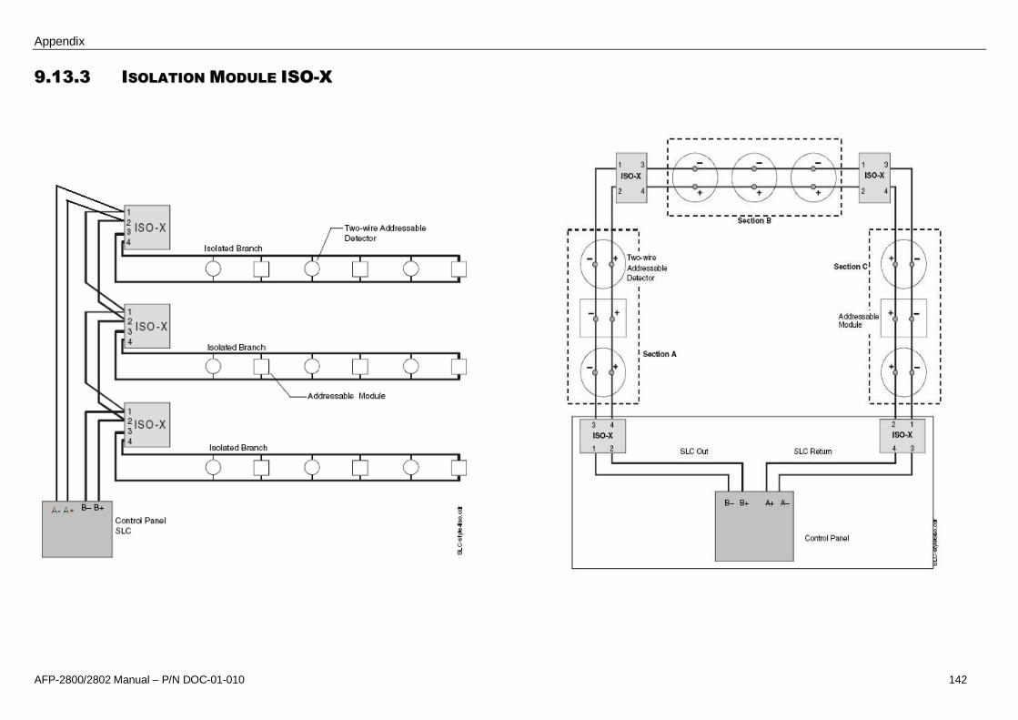
Appendix
AFP-2800/2802 Manual – P/N DOC-01-010 142
99..1133..33 IISSOOLLAATTIIOONN MMOODDUULLEE IISSOO--XX

Appendix
AFP-2800/2802 Manual – P/N DOC-01-010 143
99..1133..44 RREELLAAYY MMOODDUULLEE FFRRMM--11

Appendix
AFP-2800/2802 Manual – P/N DOC-01-010 144
99..1133..55 CCOONNTTRROOLL MMOODDUULLEE FFCCMM--11

Appendix
AFP-2800/2802 Manual – P/N DOC-01-010 145
99..1133..66 ZZOONNEE MMOODDUULLEE FFZZMM--11

Appendix
AFP-2800/2802 Manual – P/N DOC-01-010 146
99..1133..77 MMOONNIITTOORR MMOODDUULLEE FFMMMM--11
Manual CallPoint

Appendix
AFP-2800/2802 Manual – P/N DOC-01-010 147
99..1133..88 MMIINNII MMOONNIITTOORR MMOODDUULLEE FFMMMM--110011

Appendix
AFP-2800/2802 Manual – P/N DOC-01-010 148
99..1133..99 XXPP1100--MM ((1100 XX MMOONNIITTOORR MMOODDUULLEE))

Appendix
AFP-2800/2802 Manual – P/N DOC-01-010 149
99..1133..1100 XXPP66--MMAA ((66 XX CCOONNVVEENNTTIIOONNAALL ZZOONNEE IINNTTEERRFFAACCEE MMOODDUULLEE))

Appendix
AFP-2800/2802 Manual – P/N DOC-01-010 150
99..1133..1111 XXPP66--RR ((66 XX RREELLAAYY MMOODDUULLEE))

Appendix
AFP-2800/2802 Manual – P/N DOC-01-010 151
99..1133..1122 XXPP66CC ((66 XX CCOONNTTRROOLL MMOODDUULLEE))

Appendix
AFP-2800/2802 Manual – P/N DOC-01-010 152
99..1133..1133 FFDDMMRR--11 ((22 XX MMOONNIITTOORR && 22 XX RREELLAAYY))

Appendix
AFP-2800/2802 Manual – P/N DOC-01-010 153
99..1133..1144 FFAANN CCOONNTTRROOLLSS CCOONNNNEECCTTIIOONN DDIIAAGGRRAAMM
1 2 3 4 5 6 7 8
A
B
C
D
87654321
D
C
B
A
RevSize Drg.No.
titleSheet:Drawn/
Traced
Engineer
Design
Approved
This Drawing must not beused for Constructionunless signed as approved
Of:7 Columbia Court,Norwest Business ParkBaulkham Hills NSW 2153AUSTRALIATelFaxEmail: [email protected] A3No. Revision - reviseonCAD. Do notamend by hand Eng. App. Date
CopyrightThis document is &shallremain theproperty ofNotifier Inertia Fire SystemsUnauthorised useof thisdocument in any way isprohibited. Drawing File No.
CO61 2 9894 144461 2 9899 4156
Q:\JOBS\..\Nif s_f an-28-B.sch
FTR FAN START FAN STOP
SLC
+24 FTR FAN START FAN STOP
RE
PE
AT
FO
RE
AC
HF
AN
TYPICAL FAN INDICATION CONTACT ARRANGEM ENT
47K
FAULT[ OPENCCT ]
RUN[ CLOSEDCCT]
STOP[ 47K RES ]
FAN CONTROLS
FIELD I/O-2800
1 1
G.W.23/11/1
NIFS_FAN-28
RUN
FSAFR AFR
SR
COMM RUN FAULT
FR
STOP
FMM101
SR =START RELAYAFR =AIR FLOW RELAYFR = FAN RUN RELAYFS = FAN STOP RELAY
FTR
FTR
SUPPLY
POW ER
ME
CH
AN
ICA
LS
ER
VIC
ES
BO
AR
D
PFR PFRPFR = PHASE FAIL RELAY
B
+24
0V
47K
NOTE :
(A) = FAULT CONTACT NO T USED(B) = FAULT CONTACT USED
RE
PE
AT
FO
RE
AC
HF
IRE
TR
IP
+24
+ ANALOGUE LOOP
- ANALOGUE LOOP
INDICATION
-VE
+VE
LEGEND
USE ONLY R ESISTOR A OR B
SEENOTE A SEENOTE B
VIOLET
YELLOW
BLACK
RED
FTR = FIRE TRIP RELAY
FIELD CABLING
(-)
(-)
(+ )
(+ )
FTR
RUNSTOP
FAN+24
0V
BMS
SAMPLE
N/C
COM
N/O
DATA
DATA
(-)
(+)
1
2
3
45
6
7
8
9FRM-1
0
A
B
N/C
COM
N/O
DATA
DATA
(-)
(+)
1
2
3
45
6
7
8
9FRM-1
0
A
B
N/C
COM
N/O
DATA
DATA
(-)
(+)
1
2
3
45
6
7
8
9FRM-1
0
A
B
(-)
(-)
(+)
(+)
DA
TA
DEV
ICE
FM
M-1
01
01
2 3 4 56
78
9
01
23 4 5
67
89
10111213
1415
AD
DR
ESS
LOO
P
TEN
SO
NES
VY
RB
INSLC
-VE
+VE
OUT
B ADDED OUT CONN FOR SLC GW GW 10/12/04

Appendix
AFP-2800/2802 Manual – P/N DOC-01-010 154
9.14 NPS POWER SUPPLY CONNECTIONS
99..1144..11 CCOONNNNEECCTTIIOONN TTOO IIFFSS--771144 TTEERRMMIINNAATTIIOONN BBOOAARRDD

Appendix
AFP-2800/2802 Manual – P/N DOC-01-010 155
99..1144..22 CCOONNNNEECCTTIIOONN TTOO IIFFSS--772244 TTEERRMMIINNAATTIIOONN BBOOAARRDD

Notes


New South Wales(Head Office)9 Columbia WayBaulkham Hills NSW 2153
ph +61 (02 9899-4155fax +61 (0)2 9899-4156
Queensland24 Potts StreetEast Brisbane, QLD 4169
ph +61 (0)7 3391 5777fax +61 (0)7 3391 5800
Victoria32 Lambert StreetRichmond, VIC 3121
ph +61 (0)3 9421 5552fax +61 (0)3 9421 5553
Western AustraliaUnit 4, 283 Camboon RoadMalaga WA 6090
ph +61 (0)8 9270 6555fax +61 (0)8 9270 6556
New Zealand264 Mt Eden RoadAuckland
ph +64 (0)9 623 5050fax +64 (0)9 623 5060