AFB TEXAS · 2017-03-17 · Slott and ZIP CadeI 57 Executive Park South, Suite 590 Atlanta, GA...
217
RFPRODIJCED) AT GOVERNMENT FXPENSE SINSTALLATION 1RESTORATION PROGRAM SPHASE I -RECORDS SEARCH - <LACKLAND AFB TEXAS PREPARED FOR UNITED STATES AIR FORCE[ AFESC/DEV Tyndall AFB, Florida and Q. HQ ATC/DEEV Randolph AFB, Texas I.1 DTIC- ELECTED *APR 16 W FEBRUARY 1985 D AppROyed for public .Idaaq Distribution Unlumhed
Transcript of AFB TEXAS · 2017-03-17 · Slott and ZIP CadeI 57 Executive Park South, Suite 590 Atlanta, GA...
RFPRODIJCED) AT GOVERNMENT FXPENSE
SINSTALLATION1RESTORATION PROGRAM
SPHASE I -RECORDS SEARCH
- <LACKLAND AFBTEXAS
PREPARED FOR
UNITED STATES AIR FORCE[AFESC/DEV
Tyndall AFB, Floridaand
Q. HQ ATC/DEEVRandolph AFB, Texas
I.1
DTIC-ELECTED
*APR 16 W
FEBRUARY 1985 D
AppROyed for public .IdaaqDistribution Unlumhed
REPRO{)JCFD AT GOVERNMENT EXPENSE
NOT ICE
This report has been prepared for the United States AirForce by Engineering-Science for the purpose of aiding inthe Air Force Installation Restoration Program. It is notan endorsement of any product. The views expressedherein are those of the contractor and do not necessarilyreflect the official views of the publishing agency, the UnitedStates Air Force, nor the Department of Defense.
Copies of the report may be purchased from:
National Technical Information Service5285 Port Ro4'al RoadSpringfield, Virginia 22161-
Federal Government agencies and their contractorsregistered with Defense Technical Information Centershould direct requests for copies of this report to:
Defense Technical Information Center__Cameron StationAlexandria, Virginia 223114
REPRODUCED AT GOVERNMENT EXPENSE
_______FINAL
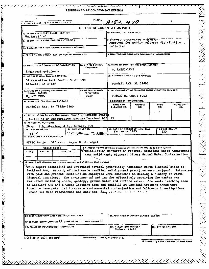
CI1. V- CLASS CA 6 O 1 141!'.rAGE.A j1II -I 7TfREPORT DOCUMENTATION PAGE
14EP-0647 SI d.*NiIV CLASS$$-IrAIION IIEIICiEMJKN!
* Unclassified
20 SECUAITV CLASSIFICATION AUTOOORI7Y 3. DISTRID UTISONIAVAILADILIITY OF REPORT
Approved for public release; distribution
2ti. DECLASSiICAT ION/OOWNGRAOING SCHEDULE unlimited
a. PERFORMING ORGANIZATION REPORT NUMBEIS) S. MONITORING ORGANIZATION REPORT NUMBERISI
6. NAME OF PERFORMING ORGANIZATION Is. OFFICE SYMBOL 7a. NAME OF MONITORING ORGANIZATION(it applicable)
*En~ineering-science IHQ AFESC/DEVP
FY CRSSi,,. Slott and ZTIP Ce6d0A 70. ADDRESS (City. Slott and ZIP CadeI
57 Executive Park South, Suite 590
Atlanta, GA 30329 Tyndall AF3, FL 32403
f-. ,A:.4E CF FUND:NG/SPCNSORING 8.OFFICE SYMBOL. 9. PROCUREMENT INSTRUMENT IDENTIFICATION NUMBER
ORGANIZATION Of applicable)*H;, ATC DEEV j DEEV F08637 83 G0005 5002
B,. ADDRESS lCilY. Slott and ZIP Code) 10. SOURCE OF FUNDING NOS.
PROGRAM PROJECT TASK WORK UNIT
Randolph AFB, TX 78150-5300 ELEMENT NO. NO. NO. NO.
1t. TIT LE 0,i~n.de Security Cksiam-1on Phase I-Records Searc I.
* Installation Restoration Program Lackland APS1 TX
12. PERSONAL AYTHOR(S)
* Thoem, R.L, Absalon, J.R.: Butner, J.R.i 12. TYPE OF REPORT 131. TIFME COVERED 14. DATE OF REPORT 11'r.. M.. 0871I 715. PGE COUNT
Final F0MSa _TO February 1985 230
16. SUPPLEM4ENTARY NOTATION
* AFESC Project Officer: Major R. A. Vogel
17. COSATI CODES lB.SUBJECT TEAMS IContiue on reverse if necessary and Woen ll by black nuemberi
*FIELD GROUP SUB. GA 'nstallaion Restoration Program; Hazardous Waste ManagementPast Solid Waste Disposal Sites: Grouna Water Contamination
19. ABSTRACT (Continue an te'se it necessary an"d idenhtify by blocnI, elunft
*his report identified and evaluated several potentially hazardous waste disposal sites at* Lackland AFB. Records of past waste handling and disposal practices were reviewed. Intervie
with past and present installation employees were conducted to develop a history of wastedisposal practices. The environmental setting for effectively receiving the wastes wasevaluated including soils, geology, ground water and surface water. one waste leaching areaeat Lackland AFB and a waste leaching area and landfill at Lacklaod Training Annex werefound to have potential to create environmental contamination and follow-on investigations(Phase II) were reconmended and outlined. L~d-,L...£
20. 01STRI OUT ION/AVALACI LIT Y OF ABSTRACT 21. ABSTRACT SECURITY CLASSIFICATION
UPICLASSIFIEOIUNLIMAITED 0 SAME AS APT. 0 OTIC USERS 0
22s. NAME OF RESPONSIBLE INDIVIDUAL 22h.. TELCP64ONE NUMDER 22c. OFFICE SYMBOLrfinclude Afro Code$
DD FORM 1473. 83 APR EDITION O .F I JAN 731IS OnSOLE 7E. a
SECURITY C.ASSIF ICATION Of THIS PAGE
7 *
INSTALLATION RESTORATION PROGRAM-PHASE I - RECORDS SEARCH
LACKLAND AFB
TEXAS
Prepared For
UNITED STATES AIR FORCE
AFESC/DEVTyndall AFB, Florida
and
HQ ATC/DEEVRandolph AFB, Texas
Accession For
NTIS GRA&I
February 1985 DTIC TAB0
Ullannouncedjustiricatio
Distributionl/
Avallability CodesPrepared By Aalndr
Dirt ISPecialENGINEER ING-.SCIENCE
57 Executive Park South, Suite 590Atlanta, Georgia 30329
-. 'a. . .
NOTICE
This report has been prepared for the United States AirForce by Engineering-Science for the purpose of aiding int-he Air Force Installation Restoration Program. It is notan endorsement of any product. The views expressedherein are those of the contractor and do not necessarilyreflect the official views of the publishing agency, the UnitedStates Air Force, nor the Department of Defense.
Copies of the report may be purchased from:
National Technical Information Service5285 Port Royal RoadSpringfield, Virginia 22161
Federal Government agencies and their contractorsregistered with Defense Technical Information Centershould direct requests for copies of this report to:
Defense Technical Information CenterCameron StationAlexandria. Virginia 22314
[..
- - - -.- >..*.*.~. -.. .-. .-. . . .
* . . ... . . * ~ A * -. .............. . * * S - - . - . . .. --
ii '
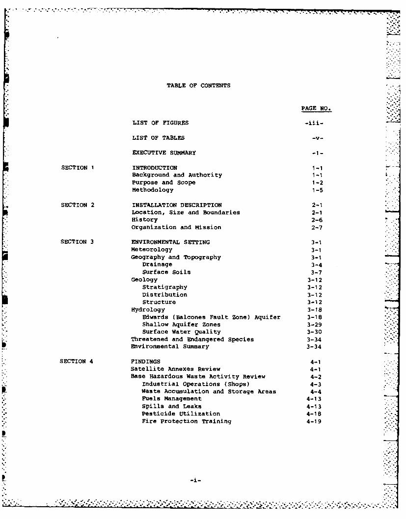
TABLE OF CONTENTS
PAGE NO.
LIST OF FIGURES -iii-
LIST OF TABLES -v-
EXECUTIVE SUMMARY -1-
SECTION 1 INTRODUCTION 1-IBackground and Authority 1-1Purpose and Scope 1-2Methodology 1-5
SECTION 2 INSTALLATION DESCRIPTION 2-1Location, Size and Boundaries 2-1History 2-6Organization and Mission 2-7
SECTION 3 ENVIRONMENTAL SETTING 3-1Meteorology 3-1Geography and Topography 3-1
Drainage 3-4
Surface Soils 3-7Geology 3-12
Stratigraphy 3-12Distribution 3-12Structure 3-12
Hydrology 3-18Edwards (Balcones Fault Zone) Aquifer 3-18Shallow Aquifer Zones 3-29Surface Water Quality 3-30
Threatened and Endangered Species 3-34Environmental Summary 3-34
SECTION 4 FINDINGS 4-1Satellite Annexes Review 4-1Base Hazardous Waste Activity Review 4-2
Industrial Operations (Shops) 4-3Waste Accumulation and Storage Areas 4-4Fuels Management 4-13Spills and Leaks 4-13Pesticide Utilization 4-18Fire Protection Training 4-19
.''u" ~.. . . .. ..4.." ......... a .* . ° - .
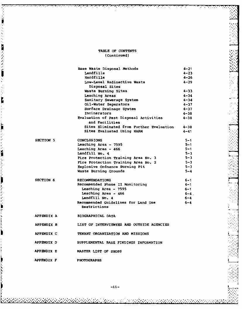
TABLE OF CONTENTS
(Continued)
Base Waste Disposal Methods 4-21Landfills 4-23Hardfills 4-26Low-Level Radioactive Waste 4-29
Disposal Sites
Waste Burning Sites 4-33Leaching Areas 4-34Sanitary Sewerage System 4-34Oil-Water Separators 4-37
Surface Drainage System 4-37Incinerators 4-38
Evaluation of Past Disposal Activities 4-38and Facilities
Sites Eliminated from Further Evaluation 4-38Sites Evaluated Using HARM 4-41
SECTION 5 CONCLUSIONS 5-1
Leaching Area - 7595 5-1Leaching Area - 466 5-1Landfill No. 4 5-3
Fire Protection Training Area No. 3 5-3Fire Protection Training Area No. 2 5-3Explosive Ordnance Burning Pit 5-3Waste Burning Grounds 5-4
SECTION 6 RECOMMENDATIONS 6-1Recommended Phase II Monitoring 6-1
Leaching Area - 7595 6-1Leaching Area - 466 6-4 .Landfill No. 4 6-4
Recommended Guidelines for Land Use 6-4Restrictions
APPENDIX A BIOGRAPHICAL DATA
APPENDIX B LIST OF INTERVIEWEES AND OUTSIDE AGENCIES
APPENDIX C TENANT ORGANIZATION AND MISSIONS
APPENDIX D SUPPLEMENTAL BASE FINDINGS INFORMATION
APPENDIX E MASTER LIST OF SHOPS
APPENDIX F PHOTOGRAPHS
-ii-
[.'..~ . .. . . .
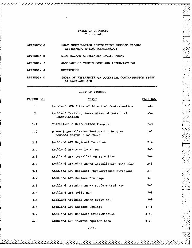
TABLE OF CONTENTS(Continued)
APPENDIX G USAF INSTALLATION RESTORATION PROGRAM HAZARD
ASSESSMENT RATING METHODOLOGY
APPENDIX H SITE HAZARD ASSESSMENT RATING FORMSItAPPENDIX I GLOSSARY OF TERMINOLOGY AND ABBREVIATIONS
APPENDIX J REFERENCES
APPENDIX K INDEX OF REFERENCES TO POTENTIAL CONTAMINATION SITESAT LACKLAND AFB,
LIST OF FIGURES
FIGURE NO. TITLE PAGE NO.
1. Lackland AFB Sites of Potential Contamination -4-
2. Lackland Training Annex Sites of Potential -5-
Contamination
1.1 Installation Restoration Program 1-3
1.2 Phase I Installation Restoration Program 1-7Records Search Flow Chart
2.1 Lackland AFB Regional Location 2-2
2.2 Lackland AFB Area Location 2-3
2.3 Lackland AFB Installation Site Plan 2-4
2.4 Lackland Training Annex Installation Site Plan 2-5
3.1 Lackland AFB Regional Physiographic Divisions 3-3
3.2 Lackland AFB Surface Drainage 3-5
3.3 Lackland Training Annex Surface Drainage 3-6
3.4 Lackland AFB Soils Map 3-8
3.5 Lackland Training Annex Soils Map 3-9
3.6 Lackland AFB Surface Geology 3-15
3.7 Lackland AFB Geologic Cross-Section 3-16
3.8 Lackland AFB Edwards Aquifer Area 3-20
-i--- "'"."
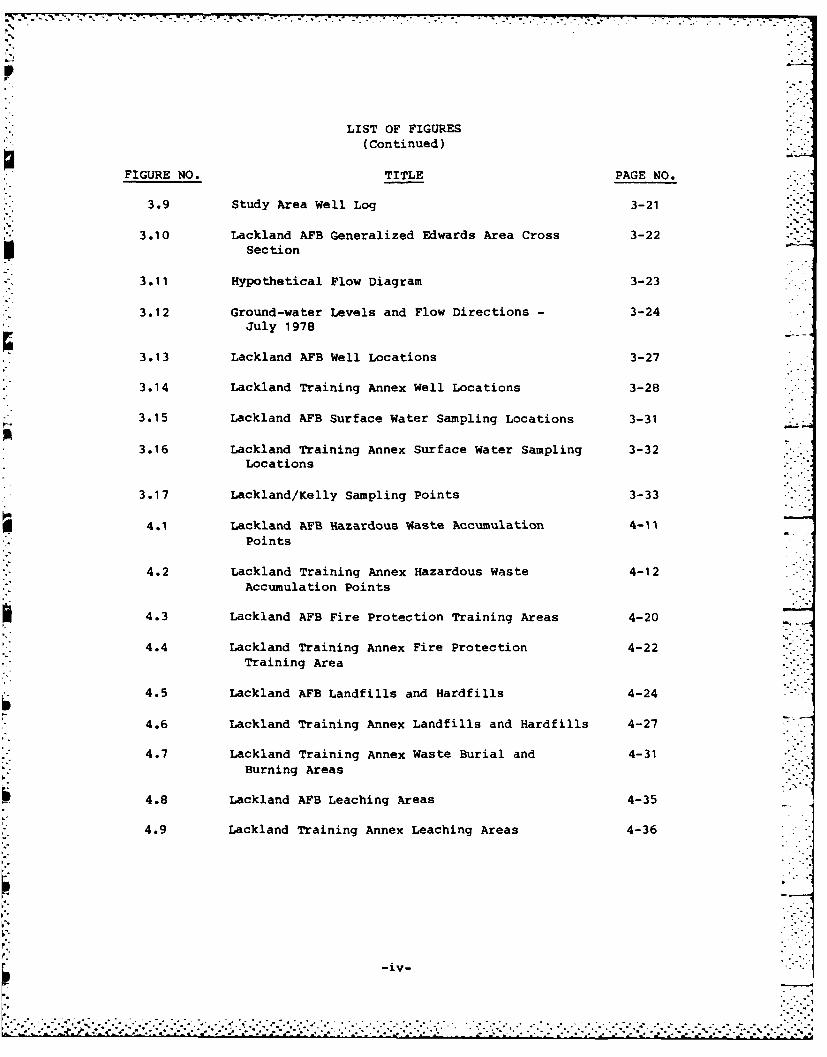
LIST OF FIGURES(Continued)
FIGURE NO. TITLE PAGE NO.
3.9 Study Area Well Log 3-21
3.10 Lackland AFB Generalized Edwards Area Cross 3-22Section
3.11 Hypothetical Flow Diagram 3-23
3.12 Ground-water Levels and Flow Directions - 3-24July 1978
3.13 Lackland AFB Well Locations 3-27
3.14 Lackland Training Annex Well Locations 3-28
3.15 Lackland AFB Surface Water Sampling Locations 3-31
3.16 Lackland Training Annex Surface Water Sampling 3-32Locations
3.17 Lackland/Kelly Sampling Points 3-33
4.1 Lackland AFB Hazardous Waste Accumulation 4-i1Points
4.2 Lackland Training Annex Hazardous Waste 4-12
Accumulation Points
4.3 Lackland AFB Fire Protection Training Areas 4-20
4.4 Lackland Training Annex Fire Protection 4-22Training Area
4.5 Lackland AFB Landfills and Hardfills 4-24
4.6 Lackland Training Annex Landfills and Hardfills 4-27
4.7 Lackland Training Annex Waste Burial and 4-31Burning Areas
4.8 Lackland AFB Leaching Areas 4-35
4.9 Lackland Training Annex Leaching Areas 4-36
-iv- .;-1
.....................-. ,. _ , . ;. .
- . .. -°-
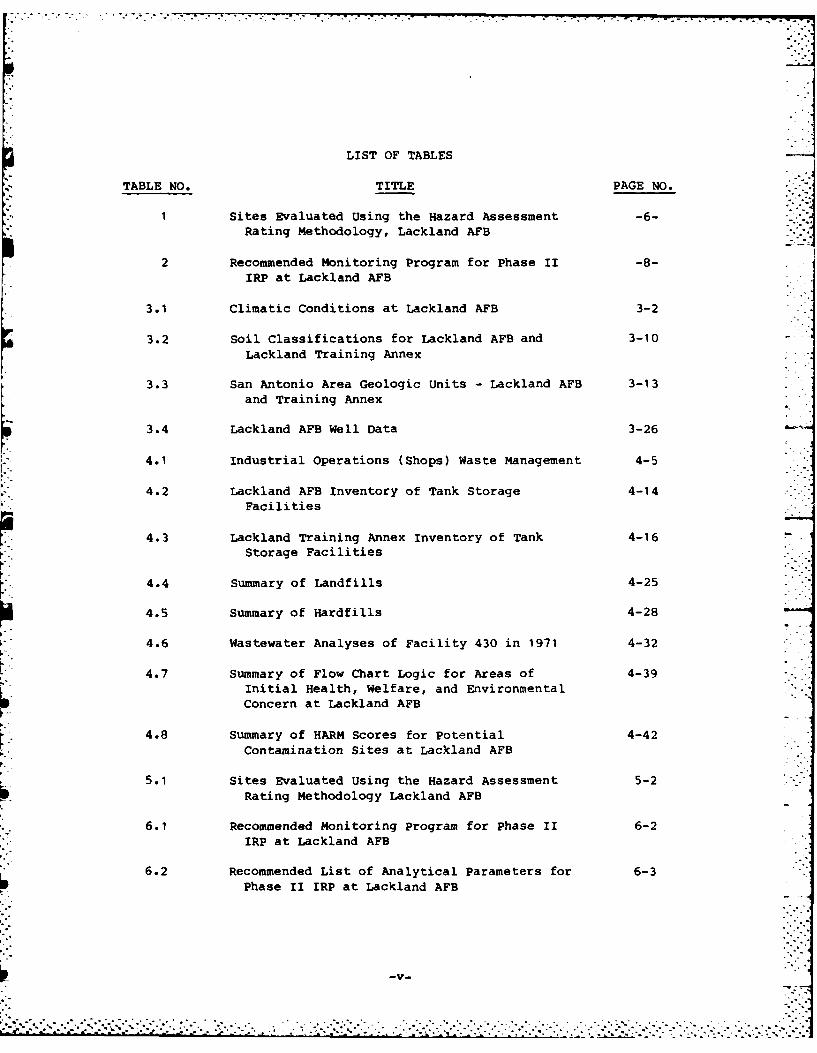
LIST OF TABLES
TABLE NO. TITLE PAGE NO.
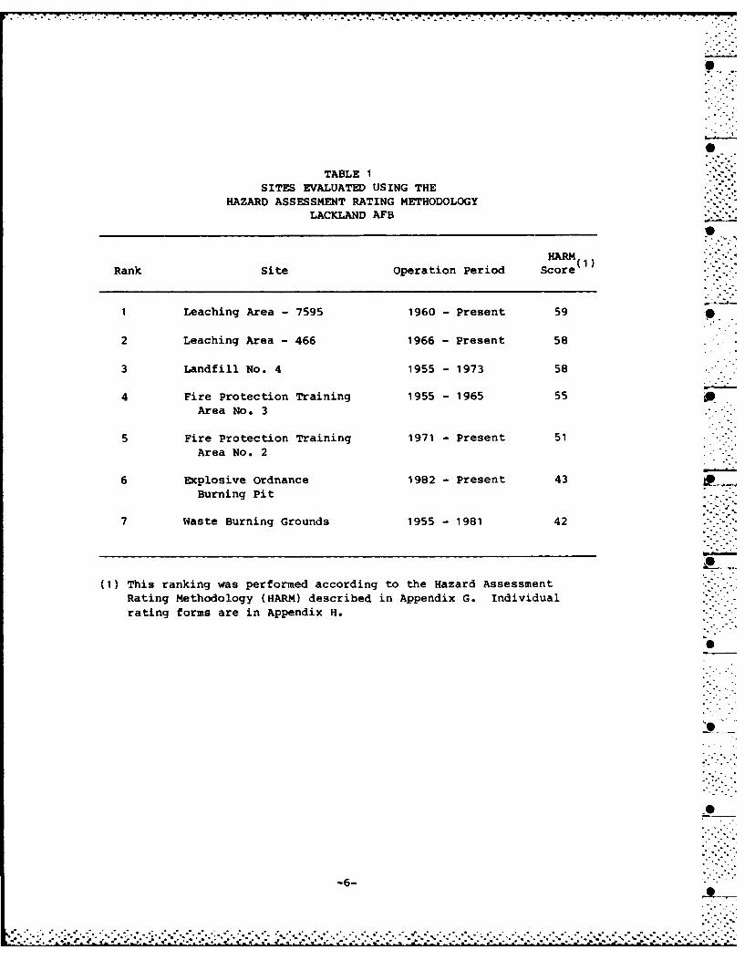
1 Sites Evaluated Using the Hazard Assessment -6-
Rating Methodology, Lackland AFB2Recommended Monitoring Program for Phase 11 -8-.
IRP at Lackland AFB
3.1 Climatic Conditions at Lackland AFB 3-2 -
3.2 Soil Classifications for Lackland AFB and 3-10Lackland Training Annex
3.3 San Antonio Area Geologic Units - Lackland AFB 3-13and Training Annex
3.4 Lackland AFB Well Data 3-26
4.1 Industrial Operations (Shops) Waste Management 4-5
4.2 Lackland AFB Inventory of Tank Storage 4-14Facilities
4.3 Lackland Training Annex Inventory of Tank 4-16Storage Facilities
4.4 Summary of Landfills 4-25
4.5 Summary of Hardfills 4-28
4.6 Wastewater Analyses of Facility 430 in 1971 4-32
4.7 Summary of Flow Chart Logic for Areas of 4-39Initial Health, Welfare, and EnvironmentalConcern at Lackland AFB
4.8 Summary of HARM Scores for Potential 4-42Contamination Sites at Lackland AFB
5.1 Sites Evaluated Using the Hazard Assessment 5-2Rating Methodology Lackland AFB
6.1 Recommended Monitoring Program for Phase II 6-2IRP at Lackland AFB
6.2 Recommended List of Analytical Parameters for 6-3Phase II IRP at Lackland AFB
........................... . .................................. .
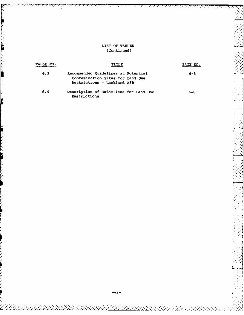
LIST OF TABLESI(Continued)
TABLE NO. TITLE PAGE NO.
6.3Recommended Guidelines at Potential 6-5Contamination Sites for Land Use
Restrictions - Lackland AFB
6.4 Description of Guidelines for Land Use 6-6Restrictions
:--J
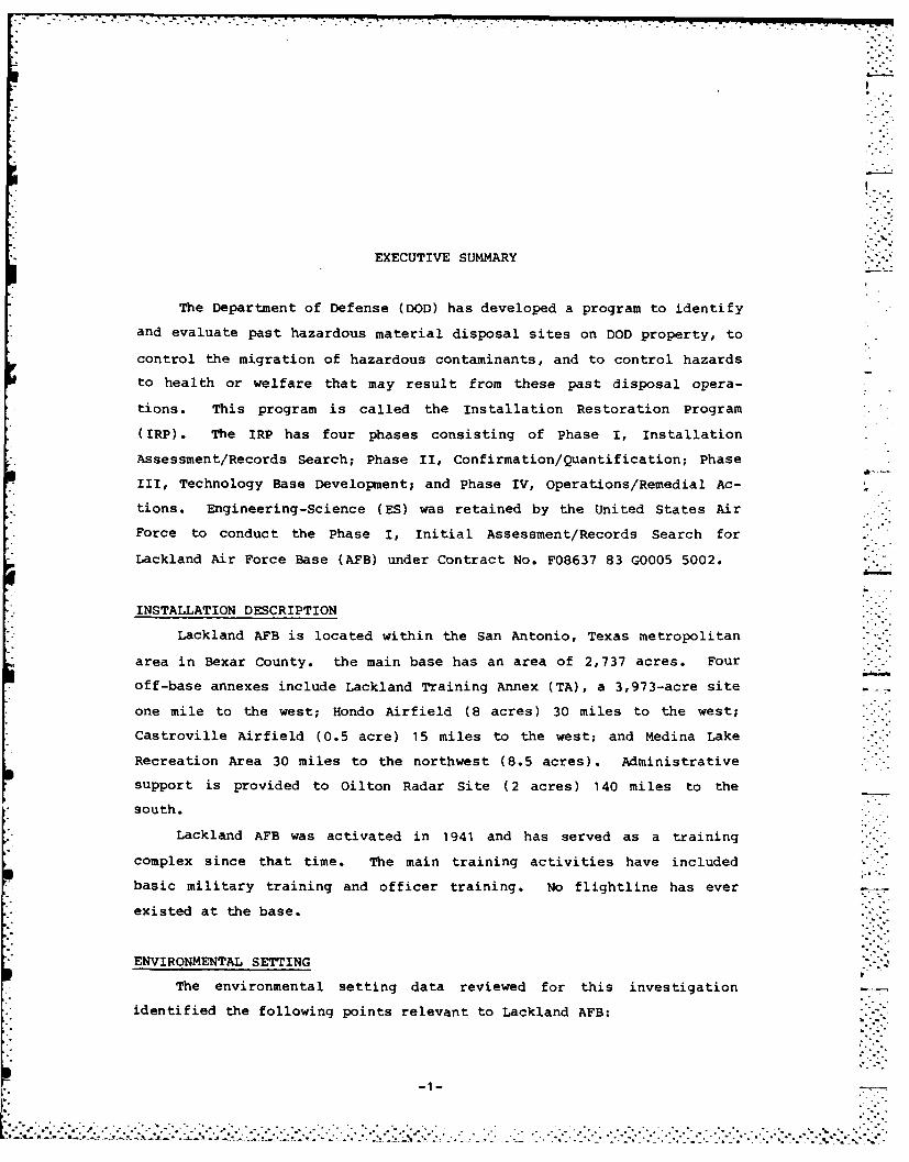
EXECUTIVE SUMMARY
The Department of Defense (DOD) has developed a program to identify
and evaluate past hazardous material disposal sites on DOD property, to
control the migration of hazardous contaminants, and to control hazards
to health or welfare that may result from these past disposal opera-
tions. This program is called the Installation Restoration Program
(IRP). The IRP has four phases consisting of Phase I, Installation
Assessment/Records Search; Phase II, Confirmation/Quantification; Phase
III, Technology Base Development; and Phase IV, operations/Remedial Ac-
tions. Engineering-Science (ES) was retained by the United States Air
* Force to conduct the Phase I, Initial Assessment/Records Search for
Lackland Air Force Base (AFB) under Contract No. F08637 83 G0005 5002.
* INSTALLATION DESCRIPTION
Lackland AFB is located within the San Antonio, Texas metropolitan
area in Bexar County. the main base has an area of 2,737 acres. Four
* off-base annexes include Lackland Training Annex (TA), a 3,973-acre site
* one mile to the west; Hondo Airfield (8 acres) 30 miles to the west;
* Castroville Airfield (0.5 acre) 15 miles to the west; and Medina Lake
Recreation Area 30 miles to the northwest (8.5 acres) . Administrative
support is provided to Oilton Radar Site (2 acres) 140 miles to the
south.
Lackland AFB was activated in 1941 and has served as a training
complex since that time. The main training activities have included
*basic military training and officer training. No flightline has ever
existed at the base.
ENVIRONMENTAL SETTING
The environmental setting data reviewed for this investigation
identified the following points relevant to Lackland AFB:
2. * . '.
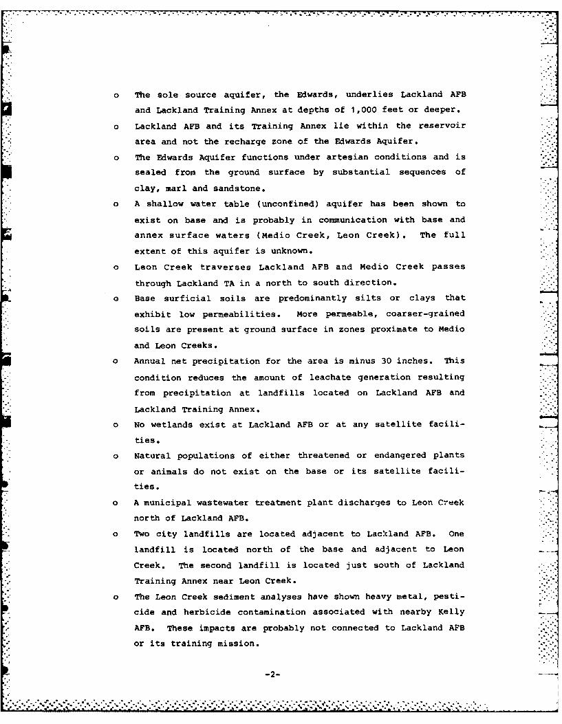
o The sole source aquifer, the Edwards, underlies Lackland AFB
and Lackland Training Annex at depths of 1,000 feet or deeper.
o Lackland AFB and its Training Annex lie within the reservoir
area and not the recharge zone of the Edwards Aquifer.
o The Edwards Aquifer functions under artesian conditions and is
sealed from the ground surface by substantial sequences of
clay, marl and sandstone.
o A shallow water table (unconfined) aquifer has been shown to
exist on base and is probably in communication with base and
annex surface waters (Medio Creek, Leon Creek). The full
extent of this aquifer is unknown.
o Leon Creek traverses Lackland AFB and Medio Creek passes
through Lackland TA in a north to south direction.
O Base surficial soils are predominantly silts or clays that
exhibit low permeabilities. More permeable, coarser-grained
soils are present at ground surface in zones proximate to Medio
and Leon Creeks.
o Annual net precipitation for the area is minus 30 inches. This
condition reduces the amount of leachate generation resulting
from precipitation at landfills located on Lackland AFB and
Lackland Training Annex.
o No wetlands exist at Lackland AFB or at any satellite facili-
% ties.
o Natural populations of either threatened or endangered plants
or animals do not exist on the base or its satellite facili-
ties.
0 A municipal wastewater treatment plant discharges to Leon Creek
north of Lackland AFB.
o Two city landfills are located adjacent to Lackland AFB. One
landfill is located north of the base and adjacent to Leon
Creek. The second landfill is located just south of Lackland
Training Annex near Leon Creek.
o The Leon Creek sediment analyses have shown heavy metal, pesti-
cide and herbicide contamination associated with nearby Kelly
AFB. These impacts are probably not connected to Lackland AFB
or its training mission.
-2- -
S *... ... .
707:-T 7:7'77
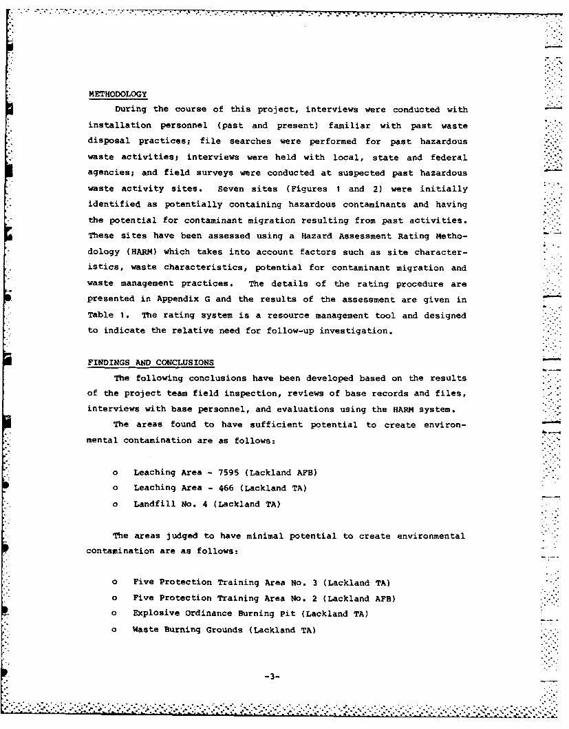
METHODOLOGY
During the course of this project, interviews were conducted with
installation personnel (past and present) familiar with past waste
disposal practices; file searches were performed for past hazardous
waste activities; interviews were held with local, state and federal
agencies; and field surveys were conducted at suspected past hazardous
waste activity sites. Seven sites (Figures 1 and 2) were initially
identified as potentially containing hazardous contaminants and having
the potential for contaminant migration resulting from past activities.
These sites have been assessed using a Hazard Assessment Rating Metho-
dology (HARM) which takes into account factors such as site character-
istics, waste characteristics, potential for contaminant migration and
waste management practices. The details of the rating procedure are
presented in Appendix G and the results of the assessment are given in
Table 1. The rating system is a resource management tool and designed
to indicate the relative need for follow-up investigation.
FINDINGS AND CONCLUSIONS
The following conclusions have been developed based on the results
of the project team field inspection, reviews of base records and files,
interviews with base personnel, and evaluations using the HARM system.
The areas found to have sufficient potential to create environ- -
mental contamination are as follows:
o Leaching Area - 7595 (Lackland AFB)
o Leaching Area - 466 (Lackland TA)
o Landfill No. 4 (Lackland TA)
The areas judged to have minimal potential to create environmental
contamination are as follows:
O Five Protection Training Area No. 3 (Lackland TA)
O Five Protection Training Area No. 2 (Lackland AFB)
o Explosive Ordinance Burning Pit (Lackland TA)
O Waste Burning Grounds (Lackland TA)
-3-
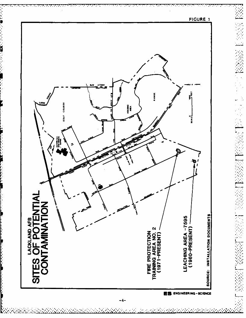
FIGURE I
U''1)
IC
(1
LEON w
02o
mW~cm
ca aLLz I- w (L
cZ C 00)
CloES ENGINEERING -SCIENCE
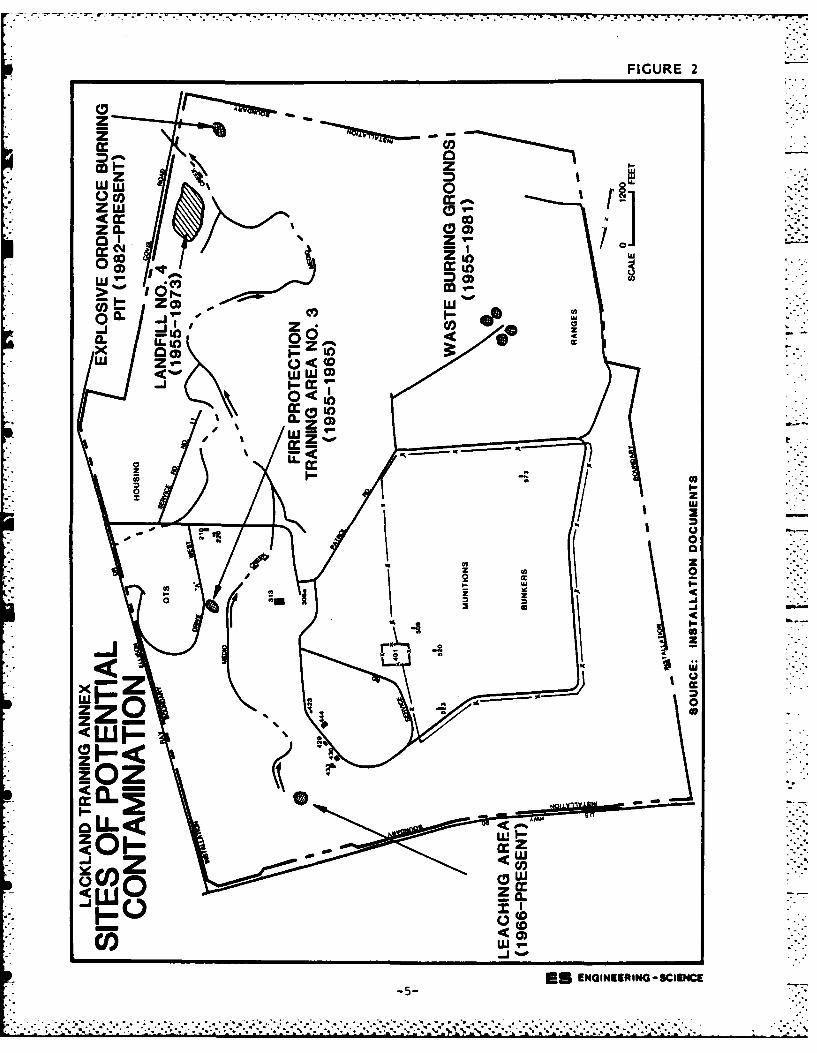
FIGURE 2
* z
Z w 0'
*cm 20.1
0I CO
w o
-Jz
IJJu WI-
0S ENIERIG-SCECM-5
*. . . . .. . . . . . . . ... C Z.. *~ ..
~ ~~~~~~~u -*' * V * ****'-* *
- . . . . . . . . -.- ,... . . . . . .
S .
TABLE ISITES EVALUATED USING THE
HAZARD ASSESSMENT RATING METHODOLOGYLACKLAND AFB
HARM,..."
Rank Site operation Period score
1 Leaching Area - 7595 1960 - Present 59 5
2 Leaching Area - 466 1966 - Present 58
3 Landfill No. 4 1955 - 1973 58
4 Fire Protection Training 1955 - 1965 55 ,Area No. 3
5 Fire Protection Training 1971 - Present 51Area No. 2 -
6 Explosive Ordnance 1982 - Present 43 09,Burning Pit
7 Waste Burning Grounds 1955 - 1981 42
(1) This ranking was performed according to the Hazard AssessmentRating Methodology (HARM) described in Appendix G. Individualrating forms are in Appendix H.
-6-
:MLL .
These sites are not recommended for further action due to the small
quantities of wastes handled, the extensive combustion which took place
to minimize residual materials, and the environmental setting factors.
RECOMMENDATIONS
Recommended guidelines for future land use restrictions at the
disposal sites are presented in Section 6. A program for proceeding
with Phase II and other IRP activities at Lackland AFB is also presented
in Section 6. The recommended actions include a soil boring, monitoring
well, sampling and analysis program to determine if contamination
exists. This program may be expanded to define the extent and type of
contamination if the initial step reveals contamination. The Phase II
recommendations are summarized in Table 2.
-7-
... ..
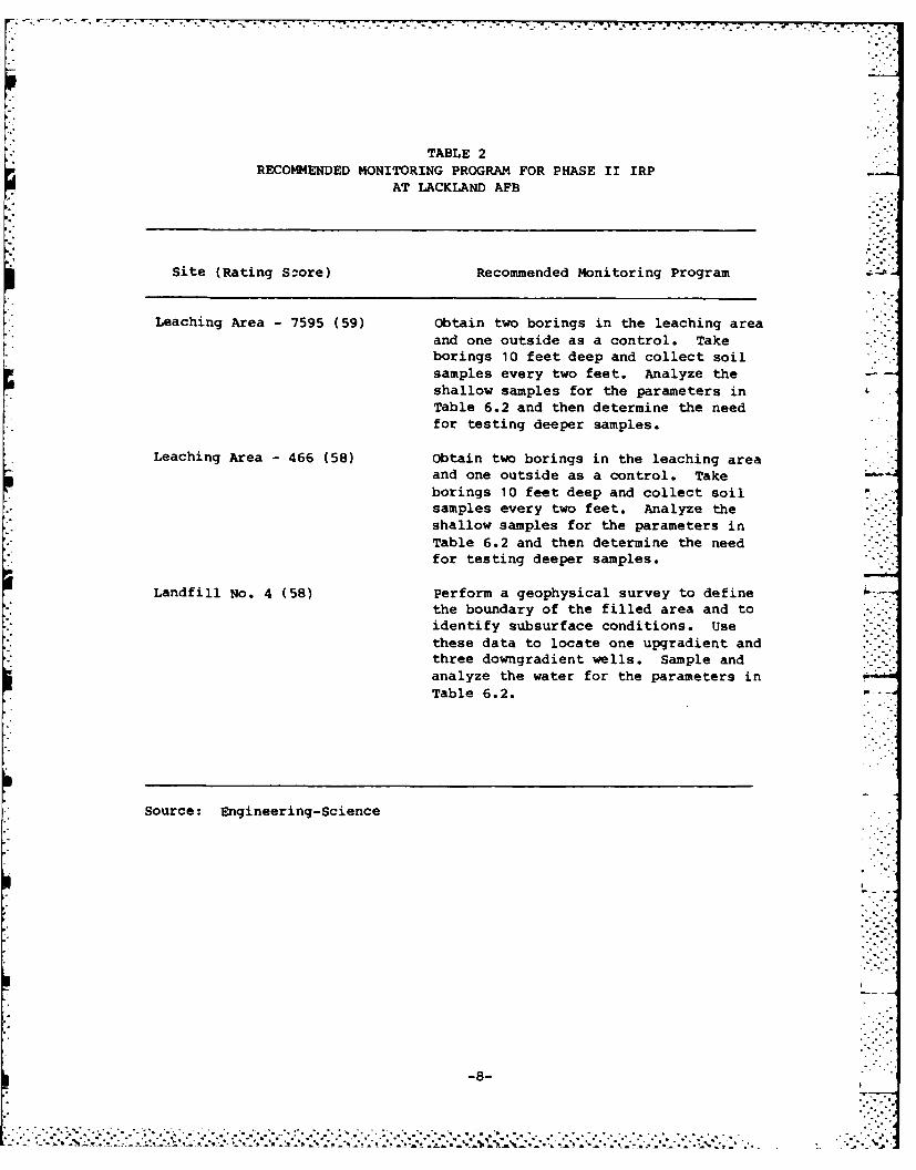
TABLE 2RECOMMENDED MONITORING PROGRAM FOR PHASE II IRP
AT LACKLAND AFB
Site (Rating Szore) Recommended Monitoring Program
Leaching Area - 7595 (59) Obtain two borings in the leaching area
and one outside as a control. Takeborings 10 feet deep and collect soilsamples every two feet. Analyze the -
shallow samples for the parameters in
Table 6.2 and then determine the needfor testing deeper samples.
Leaching Area - 466 (58) Obtain two borings in the leaching areaand one outside as a control. Takeborings 10 feet deep and collect soilsamples every two feet. Analyze theshallow samples for the parameters inTable 6.2 and then determine the needfor testing deeper samples. ..-
Landfill No. 4 (58) Perform a geophysical survey to definethe boundary of the filled area and toidentify subsurface conditions. Usethese data to locate one upgradient andthree downgradient wells. Sample andanalyze the water for the parameters inTable 6.2.
Source: Engineering-Science
-8-.
.• 5j .- n
SECTION 1 jINTRODUCTION
BACKGROUND AND AUTHORITY
The United States Air Force, due to its primary mission of defense
of the United States, has long been engaged in a wide variety of opera-
tions dealing with toxic and hazardous materials. Federal, state, and
local governments have developed strict regulations to require that
disposers identify the locations and contents of past disposal sites and
take action to eliminate hazards in an environmentally responsible
manner. The primary Federal legislation governing disposal of hazardous
waste is the Resource Conservation and Recovery Act (RCRA) of 1976, as
amended. Under Section 6003 of the Act, Federal agencies are directed
to assist the Environmental Protection Agency (EPA) and under Section
3012, state agencies are required to inventory past disposal sites, and
Federal agencies are required to make the information available to the
requesting agencies. To assure compliance with these hazardous waste
regulations, the Department of Defense (DOD) developed the Installation
Restoration Program (IRP). The current DOD IRP policy is contained in
Defense Environmental Quality Program Policy Memorandum (DEQPPM) 81-5,
dated 11 December 1981 and implemented by Air Force message dated 21
January 1982. DEQPPM 81-5 reissued and amplified all previous direc-
tives and memoranda on the Installation Restoration Program. DOD policy
is to identify and fully evaluate suspected problems associated with
past hazardous contamination, and to control hazards to health and
welfare that resulted from these past operations. The IRP is the basis
for response actions on Air Force installations under the provisions of
the Comprehensive Environmental Response, Compensation, and Liability
Act (CERCLA) of 1980, clarified by Executive Order 12316. CERCLA is the
primary legislation governing remedial action at past hazardous waste
disposal sites.
1.?-1?
,-. . . . . . . . . . .. :
PURPOSE AND SCOPE
The Installation Restoration Program is a four-phased program
(Figure 1.1) designed to assure that identification, confirmation/
quantification, and remedial actions are performed in a timely and
cost-effective manner. Each phase is briefly described below:
o Phase I - Installation Assessment/Records Search - Phase I is
to identify and prioritize those past disposal sites that may
pose a hazard to public health or the environment as a result
of contaminant migration to surface or ground waters, or have
an adverse effect by its persistence in the environment. In
this phase, it is determined whether a site requires further
action to confirm an environmental hazard or whether it may be
considered to present no hazard at this time. If a site re-
quires immediate remedial action, such as removal of abandoned
drums, the action can proceed directly to Phase IV. Phase I is
a basic background document for the Phase II study.
o Phase II - Confirmation/Quantification - Phase II is to define
and quantify, by preliminary and comprehensive environmental
and/or ecological survey, the presence or absence of contami-
nation, the extent of contamination, waste characterization
(when required by the regulatory agency), and to identify sites
or locations where remedial action is required in Phase IV.
Research requirements identified during this phase will be
included in the Phase III effort of the program.
o Phase III - Technology Base Development - Phase III is to
develop a sound data base upon which to prepare a comprehensive
remedial action plan. This phase includes implementation of
research requirements and technology for objective assessment
of adverse effects. A Phase III requirement can be identified
at any time during the program.
o Phase IV - Operations/Remedial Actions - Phase IV includes the
preparation and implementation of the remedial action plan.
1-2
......... . .............- o .o ° , •
° -. •.,...• . .. .. o. °-., o °. ., .. .. .. °.. .....-. "'
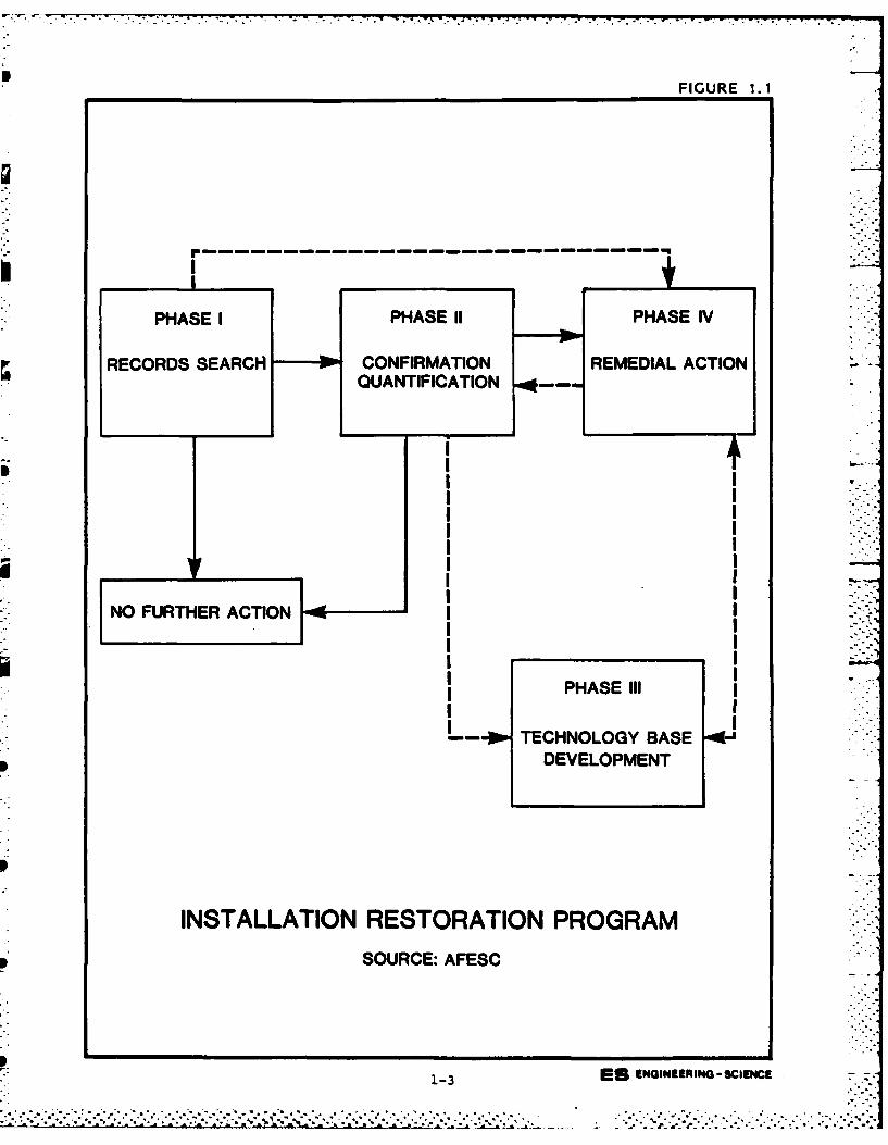
FIGURE 1. 1
PHASE I PHASE 11 PHASE IV
RECORDS SEARCH 10CONFIRMATION REMEDIAL ACTION
QUANTIFICATION -
PHS II
L.0 TEHOOYBAE I11-
NONFUTHER ACTION RETRTO PRGA
I IC:AES
1-IE EGN R ING-sl
1 r. .n n• - .
Engineering-Science (ES) was retained by the United States Air
Force to conduct the Phase I Records Search at Lackland AFB under Con-
tract No. F08637 83 G0005 5002. This report contains a summary and an
evaluation of the information collected during Phase I of the IRP and
recommended follow-on actions.
The land area included as part of the Lackland AFB study is as fol-
lows:
Lackland AFB - 2737 acres
Lackland Training Annex - 3973 acres
Hondo Airfield - 8 acres
Castroville Airfield - 0.5 acre
Medina Lake Recreation Area - 8.5 acres
Oilton Radar Site - 2 acres• ..
The activities performed as a part of the Phase I study scope
included the following:
- Review of site records
- Interviews with personnel familiar with past generation and
disposal activities
- Survey of types and quantities of wastes generated
- Determination of current and past hazardous waste treatment,
storage, and disposal activities
- Description of the environmental setting at the base
- Review of past disposal practices and methods
- Reconnaissance of field conditions
- Collection of pertinent information from federal, state and
local agencies
- Assessment of the potential for contaminant migration
- Development of recommendations for follow-on actions
ES performed the on-site portion of the records search during
September, 1984. The following team of professionals were involved:
- R. L. Thoem, Environmental Engineer and Project Manager, MS
Sanitary Engineering, 21 years of professional experience.
1-4
- ............
.. -.- . .... .. ' .. ' ....... .. .' . ." .'. '.4.." ... ,....% "....'.-. ... .... .... .. ' .... ' ..... -... ,..' ...-.. . ,. ... .'.'. " .
- J. R. Absalon, Hydrogeologist, BS Geology, 10 years of profes- Isional experience. ..
- J. R. Butner, Environmental Scientist, MS Environmental Engi-
neering Sciences, 5 years of professional experience.
More detailed information on these three individuals is presented in
Appendix A.
METHODOLOGY
The methodology utilized in the Lackland AFB Records Search began ....
with a review of past and present industrial operations conducted at the
base. Information was obtained from available records such as shop
files and real property files, as well as interviews with 61 past and
present base employees from various operating areas. Those interviewed
included current and past personnel associated with civil engineering,
fuels management, roads and grounds maintenance, fire protection, real
property, history, bioenvironmental engineering, recreation, entomology,
ordnance disposal, radiation safety, various training activities, and
other areas. A listing of interviewee positions with approximate years
of service is presented in Appendix B.
Concurrent with the employee interviews, the applicable federal,
state and local agencies were contacted for pertinent study area related
environmental data. The agencies contacted are listed below and in
Appendix B.
o U.S. Geological Survey, Water Resources Division (San
Antonio, TX)
o U.S. Department of Agriculture, Soil Conservation Service
(Hondo, TX)
o Edwards Underground Water District (San Antonio, TX)
o Texas Department of Health, Solid Waste Management Program
(San Antonio, TX)
o Texas Department of Water Resources, Water Quality Division
(San Antonio, TX)
1-5
_° - o • so o-... ..-..,.-. . . ,...... . °.........*.. ... .. o.
The next step in the activity review was to identify all sources of
hazardous waste generation and to determine the past management prac-
tices regarding the use, storage, treatment, and disposal of hazardous
materials from the various sources on the base. Included in this part
of the activities review was the identification of all known past dis-
posal sites and other possible sources of contamination such as spill
areas.
A general ground tour and an overflight of the identified sites
were made by the ES Project Team to gather site-specific information
including: (1) general observations of existing site conditions; (2)
visual evidence of environmental stress; (3) presence of nearby drainage
ditches or surface waters; and (4) visual inspection of these water
bodies for any obvious signs of contamination or leachate migration.
A decision was then made, based on all of the above information,
whether a potential hazard to health, welfare or the environment exists
at any of the identified sites using the Flow Chart shown in Figure 1.2.
If no potential existed, the site was deleted from further considera-
tion. For those sites where a potential hazard was identified, a deter-
mination of the need for IRP evaluation/action was made by considering
site-specific conditions. If no further IRP evaluation was determined
necessary, then the site was referred to the installation environmental
program for appropriate action. If a site warranted further investi-
gation, it was evaluated and rated using the Hazard Assessment Rating
Methodology (HARM). The HARM score is a resource management tool which
indicates the relative potential for adverse effects on health or the
environment at each site evaluated.
1 -6. . .'- *
__________________________________ __°2.
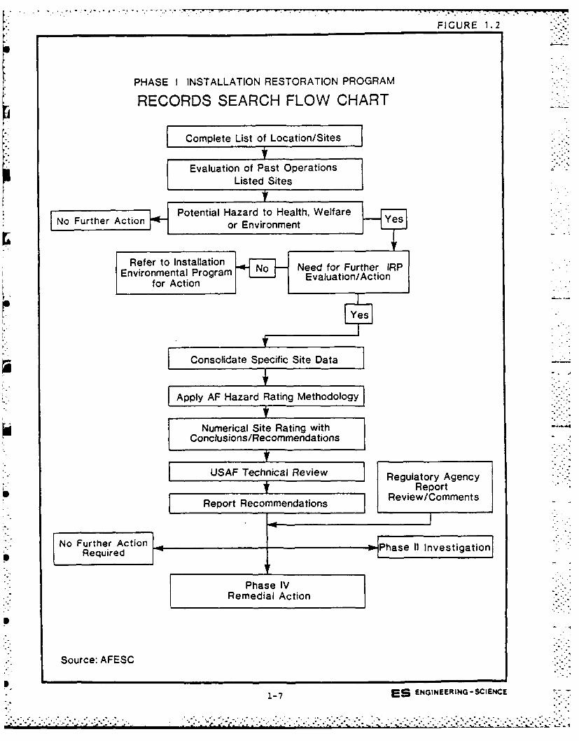
FIGURE 1.-2
PHASE I INSTALLATION RESTORATION PROGRAM
RECORDS SEARCH FLOW CHART
Complete List of Location/Sites -
Evaluation of Past OperationsListed Sites
I Potential Hazard to Health, Welfare i-
No Further Action or Environment
Refer to Installation
Environmental Program Need for Further IRPfor Action Evaluation/Action
Yes
Consolidate Specific Site Data -
Apply AF Hazard Rating Methodology
Numerical Site Rating withConclusions/Recommendations
USAF Technical Review Regulatory Agency' Report
Report Recommendations Review/Comments
No Further Action - " -"Required
P
Phase IVRemedial Action
Source: AFESC
1E
". . .. .. .. " ... ,." ."." ,.-, • . ." . "-. .......-. ...".. . ..". .,.... -. .,.-..",". . . .... .. , , • .' . .'.
.-- , -.-----..--------------
SECTION 2
INSTALLATION DESCRIPTION
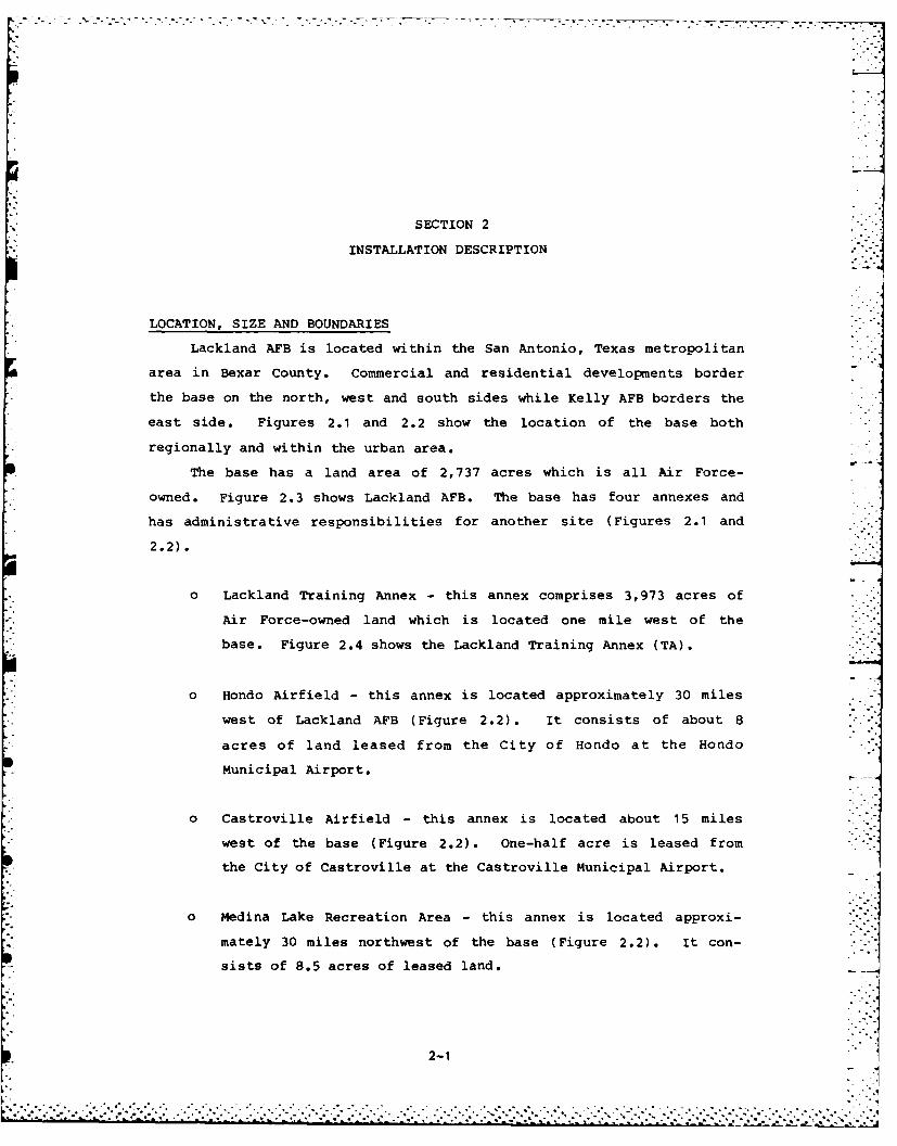
LOCATION, SIZE AND BOUNDARIES
Lackland AFB is located within the San Antonio, Texas metropolitan
area in Bexar County. Commercial and residential developments border
the base on the north, west and south sides while Kelly AFB borders the
east side. Figures 2.1 and 2.2 show the location of the base both
regionally and within the urban area.
The base has a land area of 2,737 acres which is all Air Force-
owned. Figure 2.3 shows Lackland AFB. The base has four annexes and
has administrative responsibilities for another site (Figures 2.1 and
2.2).
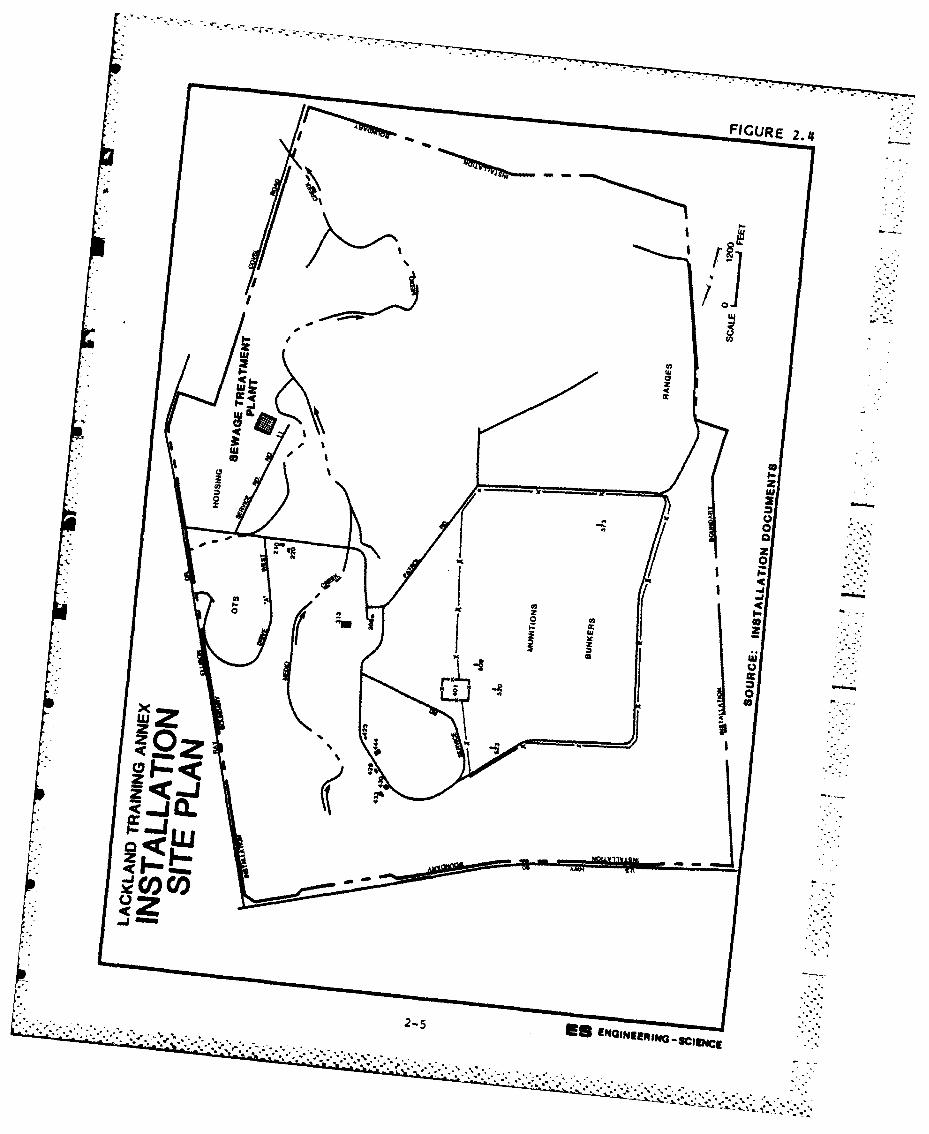
o Lackland Training Annex - this annex comprises 3,973 acres of
Air Force-owned land which is located one mile west of the
base. Figure 2.4 shows the Lackland Training Annex (TA).
0 Hondo Airfield - this annex is located approximately 30 miles
west of Lackland AFB (Figure 2.2). It consists of about 8
acres of land leased from the City of Hondo at the Hondo
Municipal Airport.
o Castroville Airfield - this annex is located about 15 miles
west of the base (Figure 2.2). One-half acre is leased from
the City of Castroville at the Castroville Municipal Airport.
o Medina Lake Recreation Area - this annex is located approxi-
mately 30 miles northwest of the base (Figure 2.2). It con-
sists of 8.5 acres of leased land.
2-1
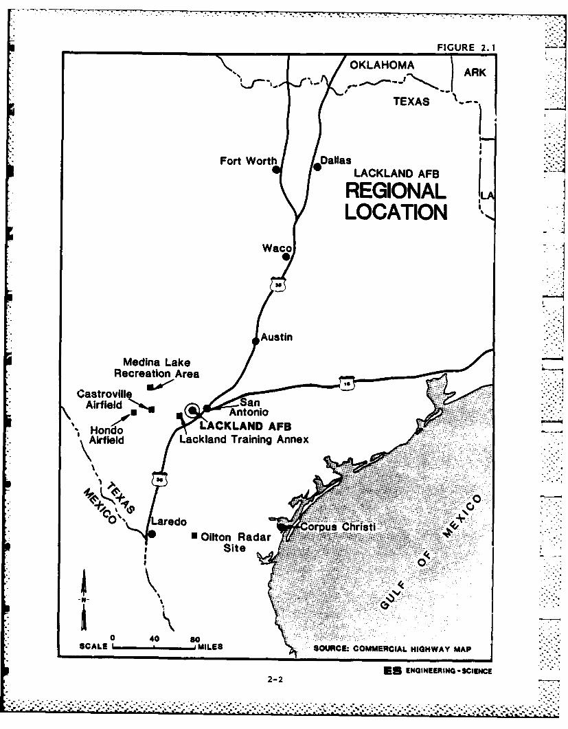
______________________________FIGURE 2. 1
OKLAHOMAAR
TEXAS ?:2:Fort Worth Dallas
0 LACKLAND AFB
REGIONAL ILALOCATION
Waco
Asi
Medinia Lake -
Recreation Area
CastrovilleAirfieldAnoi
HondoCKLAND AFB S-
Airfield akadTannAne
0" Lardo orps Christi 44* Ollton Radar
00
SCALE ' MILES SOURCE: COMMERCIAL HIGHWAY MAP
ES ENGINEERING - SCIENCE2-2
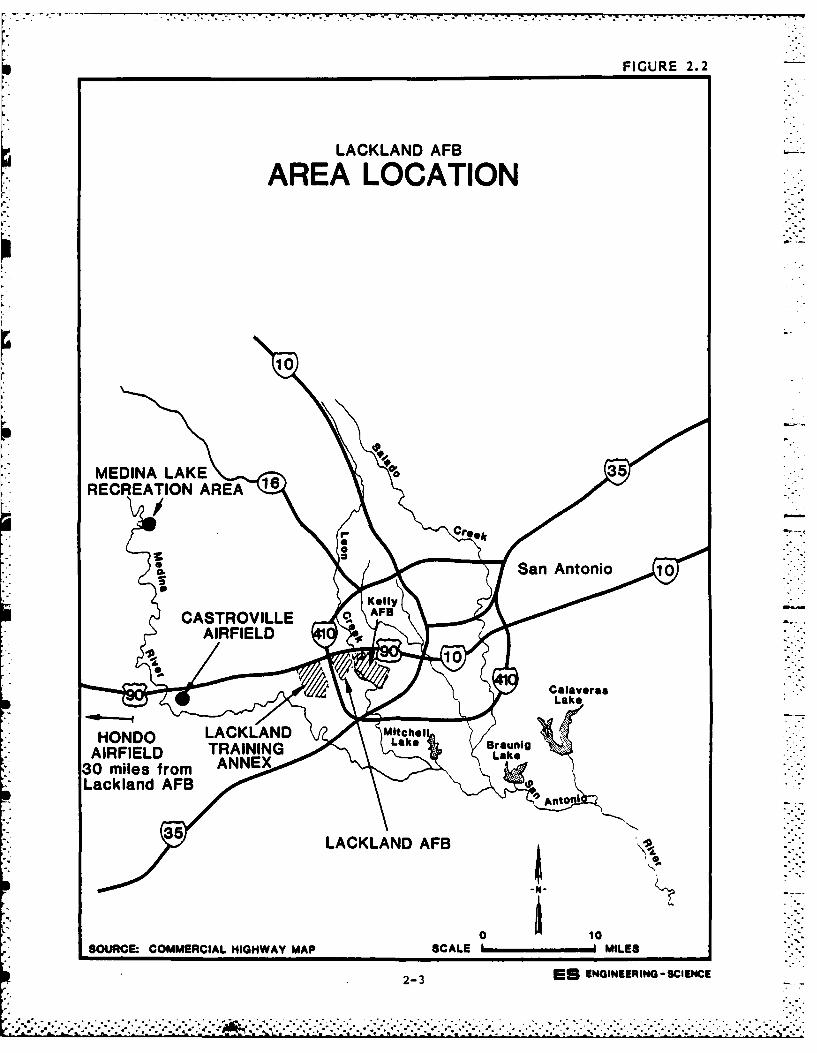
FIGURE 2.2
LACKLAND AFB
AREA LOCATION
10
MEDINA LAKE 3 5RECREATION AREA
LSclan AFBn 1
CASLACKLAND AFB
101SOURC: COMERCIL HIHWAYMAP SALE vMIS
2-3 S ~~LaeNNERG-CHC
. AKLN Michl
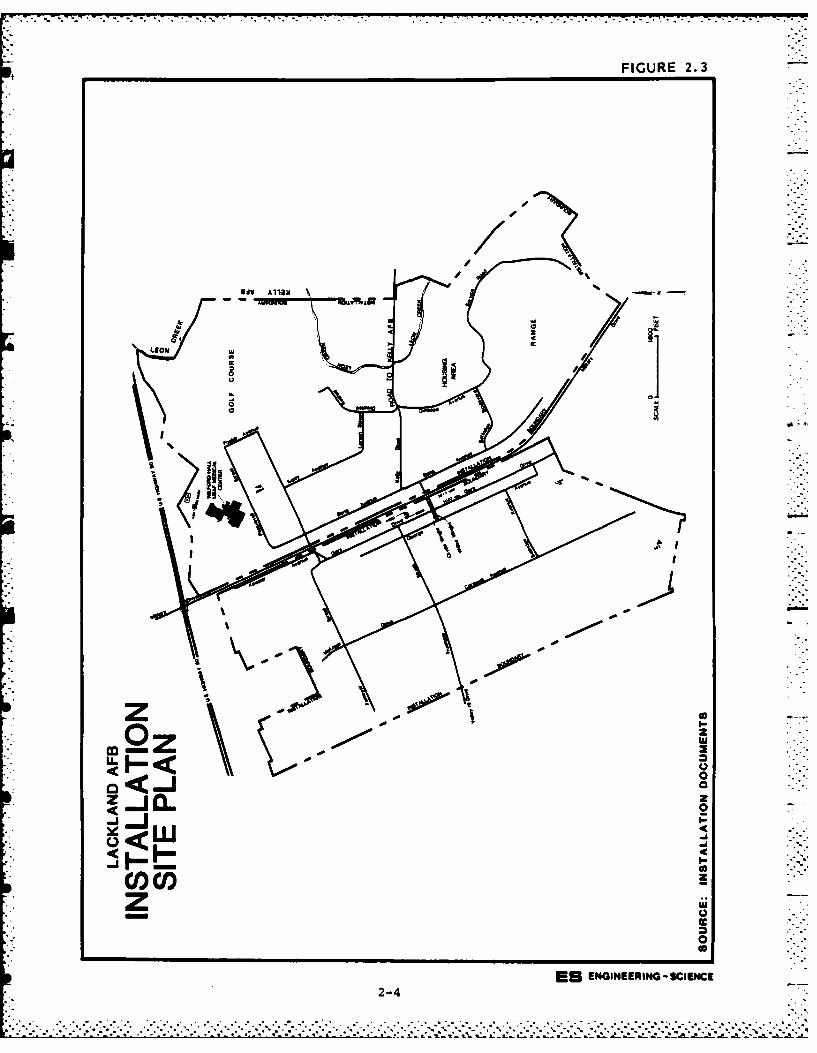
FIGURE 2.3
-t*
0
zo* 0
doa
.00
0 I-
U- 0
zzLUU
0) cl0
0
ES ENGINEERING - SCIENCE2-4
IG R .
44;Iiu
w- JUSCPERNGSIEC
In 1 0
1 .
0 Oilton Radar Site - Lackland AFB provides only administrative
support at this radar facility; the personnel and all other
support are under the Tactical Air Command (TAC). The site
consists of approximately 2 acres of leased land which is
located in Webb County 140 miles south of Lackland AFB (Figure
2.1) and two miles north of Oilton, Texas.
HISTORY
From 1917 to 1941 the site of Lackland AFB was used as a bombing
range by Kelly AFB. Lackland AFB was activated in 1941 and has served
as a training complex since that time. No flightline has ever existed
at the base. Except for a few years since 1941, Lackland AFB has pro-
vided basic military training for all persons entering the Air Force.
It has provided pre-flight training and since 1944 has had the USAF
Officer Candidate School (now Officer Training School, OTS). Since 1957
Lackland has had a major hospital on base, Wilford Hall USAF Medical
Center. Lackland has been involved in several other training functions
including recruiters, air and security police, cryptography, marksman-
ship, social actions, and languages for foreign military personnel.
In 1961 Lackland expanded by acquiring a portion of the Medina
Facility (Lackland Training Annex) from the Atomic Energy Commission
(AEC). The entire site was taken over by the Air Force in 1966. The
Medina facility was started by the AEC in 1955 and was a weapons mainte-
nance and storage facility. The Medina annex, under the Air Force, has
included the OTS, security service activities, firing ranges, missile
repair training, munitions storage and explosive ordnance disposal
(EOD).
The Hondo Annex has served as a training facility for the OTS since
about 1964 when land was first leased at the airport. The lease pro-
vides for use of a combination hangar/classroom/administration building,
parking lot, access roads, runways and a tie-down area for 75 airplanes.
Currently T-41 aircraft are used for training.
The lease for the Castroville annex provides for use of the runways
and a small area for aircraft storage (emergencies only). Land has been
leased at this annex since 1966. No personnel or structures are at the
site and it has been used only for emergency aircraft landing situa-
tions.
2-6
.~ ~ ~ . . . .
Medina Lake Recreation Area provides the recreational facilities 7
including a main pavilion, picnic shelters and a marina for base person-
nel. The recreation area has been leased since 1982.
The land at the Oilton radar site has been leased since 1972. The
Federal Aviation Administration (FAA) utilizes some of the site and was
at the location prior to the Air Force. The Air Force installation
includes two antennas and support facilities.
ORGANIZATION AND MISSION
The host unit at Lackland AFB (including Lackland TA) is the Air
Force Military Training Center (AFMTC). Major units within the AFMTC
include the Basic Military Training School, 3250th Technical Training
Wing, Defense Language Institute, 3700th Air Base Group, Resource
Management, and the 3700th Personnel Resource Group.
The primary mission of the AFMTC is to provide basic training for
persons entering the Air Force. The Basic Military Training School
provides this training. The 3250th Technical Training Wing provides a
variety of training activities in fields such as cryptographic repair,
recruiting, social actions, security police and marksmanship. This wing
includes three groups, the 3270th, 3280th and 3290th. The primary
mission of the Defense Language Institute is to control all Department
of Defense (DOD) English language training programs and courses for
American and foreign military programs. The 3700th Air Base Group --
manages and maintains all base facilities and service functions. Re-
source Management functions include all supply, transportation, and
other logistical support for the base. All military and civilian per-
sonnel support is provided by the 3700th Personnel Resource Group.
Descriptions of the major tenants at Lackland AFB and their mis-
sions are presented in Appendix C.
. . .. .. . , ...
7 -. 7
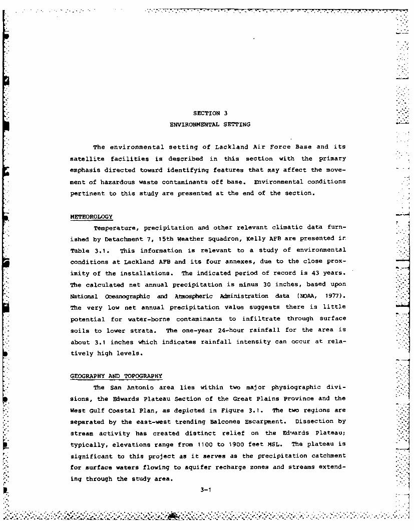
SECTION 3
ENVIRONMENTAL SETTING
The environmental setting of Lackland Air Force Base and its
satellite facilities is described in this section with the primary
emphasis directed toward identifying features that may affect the move-
ment of hazardous waste contaminants off base. Environmental conditions
pertinent to this study are presented at the end of the section.
METEOROLOGY "
Temperature, precipitation and other relevant climatic data furn-
ished by Detachment 7, 15th Weather Squadron, Kelly AFB are presented in
Table 3.1. This information is relevant to a study of environmental
conditions at Lackland AFB and its four annexes, due to the close prox-
imity of the installations. The indicated period of record is 43 years.
The calculated net annual precipitation is minus 30 inches, based upon
National oceanographic and Atmospheric Administration data (NOAA, 1977).
The very low net annual precipitation value suggests there is little
potential for water-borne contaminants to infiltrate through surface
soils to lower strata. The one-year 24-hour rainfall for the area is
about 3.1 inches which indicates rainfall intensity can occur at rela-
tively high levels.
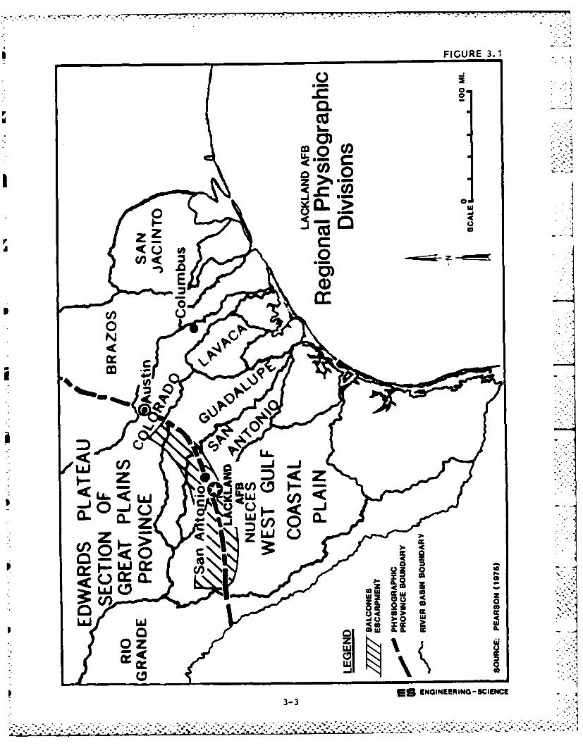
GEOGRAPHY AND TOPOGRAPHY
The San Antonio area lies within two major physiographic divi-
sions, the Edwards Plateau Section of the Great Plains Province and the
West Gulf Coastal Plan, as depicted in Figure 3.1. The two regions are
separated by the east-west trending Balcones Escarpment. Dissection by Istream activity has created distinct relief on the Edwards Plateau;
typically, elevations range from 1100 to 1900 feet MSL. The plateau is
significant to this project as it serves as the precipitation catchment
for surface waters flowing to aquifer recharge zones and streams extend-
ing through the study area.
3-1
" 1
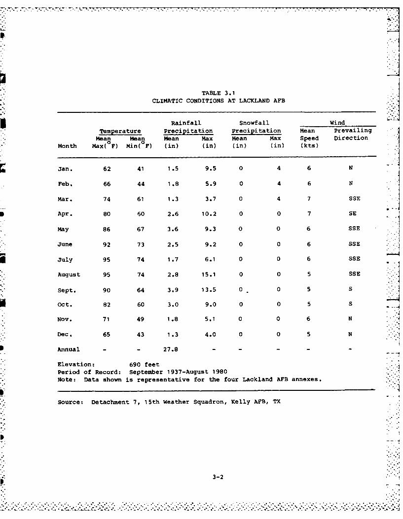
TABLE 3.1CLIMATIC CONDITIONS AT LACKLAND AFB
Rainfall Snowfall wind -Temperature Precipitation Precipitation Mean Prevailing
Mean Mean Mean Max Mean Max Speed Direction0 0
Month Max( F) Min( F) (in) (in) (in) (in) (kts)
Jan. 62 41 1.5 9.5 0 4 6 N
Feb. 66 44 1.8 5.9 0 4 6 N
Mar. 74 61 1.3 3.7 0 4 7 SSE
IApr. 80 60 2.6 10.2 0 0 7 SE
May 86 67 3.6 9.3 0 0 6 SSE
June 92 73 2.5 9.2 0 0 6 SSE
jJuly 95 74 1.7 6.1 0 0 6 SSE
August 95 74 2.8 15.1 0 0 5 SSE
Sept. 90 64 3.9 13.5 0 0 5 5
Oct. 82 60 3.0 9.0 0 0 5 5
Nov. 71 49 1.8 5.1 0 0 6 N
Dec. 65 43 1.3 4.0 0 0 5 N
IAnnual - - 27.8 - - - -
*Elevation: 690 feet* Period of Record: September 1937-August 1980
* Note: Data shown is representative for the four Lackland AFB annexes.
Source: Detachment 7, 15th Weather Squadron, Kelly AFB, TX
3-2
UFIGURE 3.1
0L.
OCz >
cn< <
I a
IU6WU. <9 ENINERN 19 CCI
0 3-3
- .. . . . . . . . . . . ... . - .
.. .. .. .. . .. .. .. . .. .. .. .. . .. .. .. .
z~..~ z -I
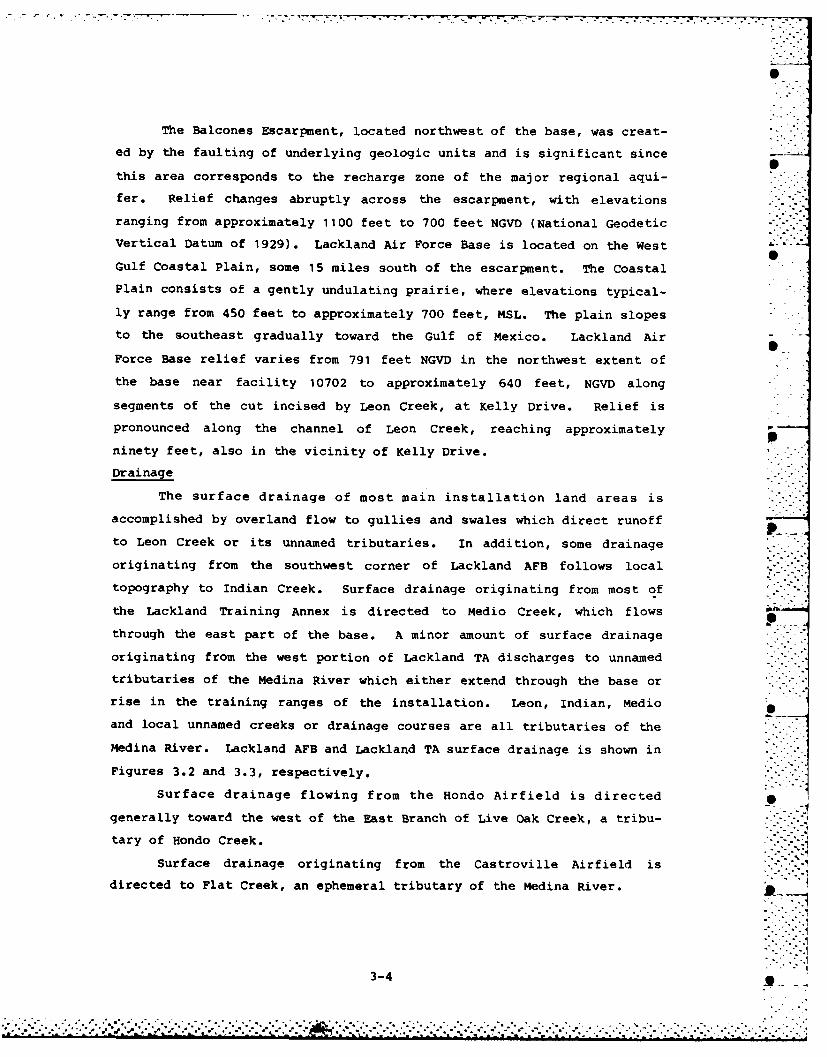
The Balcones Escarpment, located northwest of the base, was creat-
ed by the faulting of underlying geologic units and is significant since
this area corresponds to the recharge zone of the major regional aqui-
fer. Relief changes abruptly across the escarpment, with elevations
ranging from approximately 1100 feet to 700 feet NGVD (National Geodetic
Vertical Datum of 1929). Lackland Air Force Base is located on the West
Gulf Coastal Plain, some 15 miles south of the escarpment. The Coastal
Plain consists of a gently undulating prairie, where elevations typical-
ly range from 450 feet to approximately 700 feet, MSL. The plain slopes
to the southeast gradually toward the Gulf of Mexico. Lackland Air
Force Base relief varies from 791 feet NGVD in the northwest extent of
the base near facility 10702 to approximately 640 feet, NGVD along
segments of the cut incised by Leon Creek, at Kelly Drive. Relief is
pronounced along the channel of Leon Creek, reaching approximately
ninety feet, also in the vicinity of Kelly Drive.
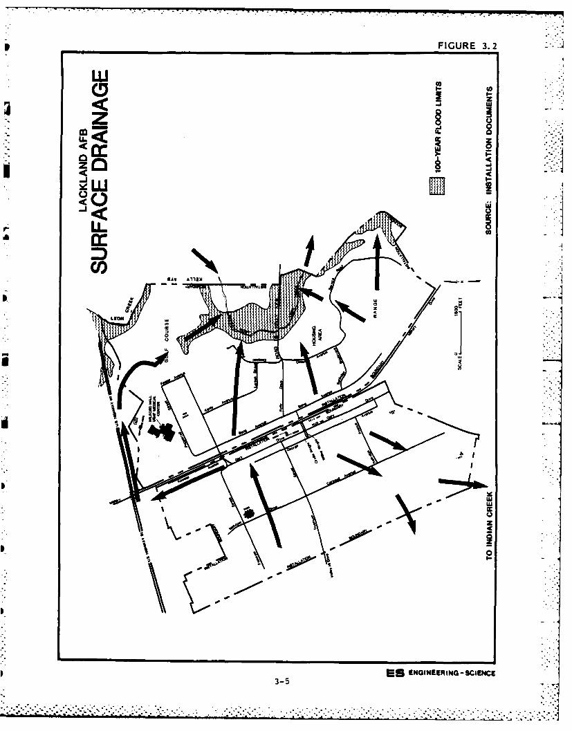
Drainage
The surface drainage of most main installation land areas is
accomplished by overland flow to gullies and swales which direct runoff
to Leon Creek or its unnamed tributaries. In addition, some drainage
originating from the southwest corner of Lackland AFB follows local
topography to Indian Creek. Surface drainage originating from most of
the Lackland Training Annex is directed to Medio Creek, which flows
through the east part of the base. A minor amount of surface drainage
originating from the west portion of Lackland TA discharges to unnamed
tributaries of the Medina River which either extend through the base or
rise in the training ranges of the installation. Leon, Indian, Medio
and local unnamed creeks or drainage courses are all tributaries of the
Medina River. Lackland AFB and Lackland TA surface drainage is shown in
Figures 3.2 and 3.3, respectively.
Surface drainage flowing from the Hondo Airfield is directed
generally toward the west of the East Branch of Live Oak Creek, a tribu- -
tary of Hondo Creek. .. -
Surface drainage originating from the Castroville Airfield isdirected to Flat Creek, an ephemeral tributary of the Medina River.
3-4 _
.~ -. • " .
p FIGURE 3.2
cc 0
zz
-u-CIOr LL
IC
@A lli
z
II
ES ENGINEER ING - SCIENCE3-5
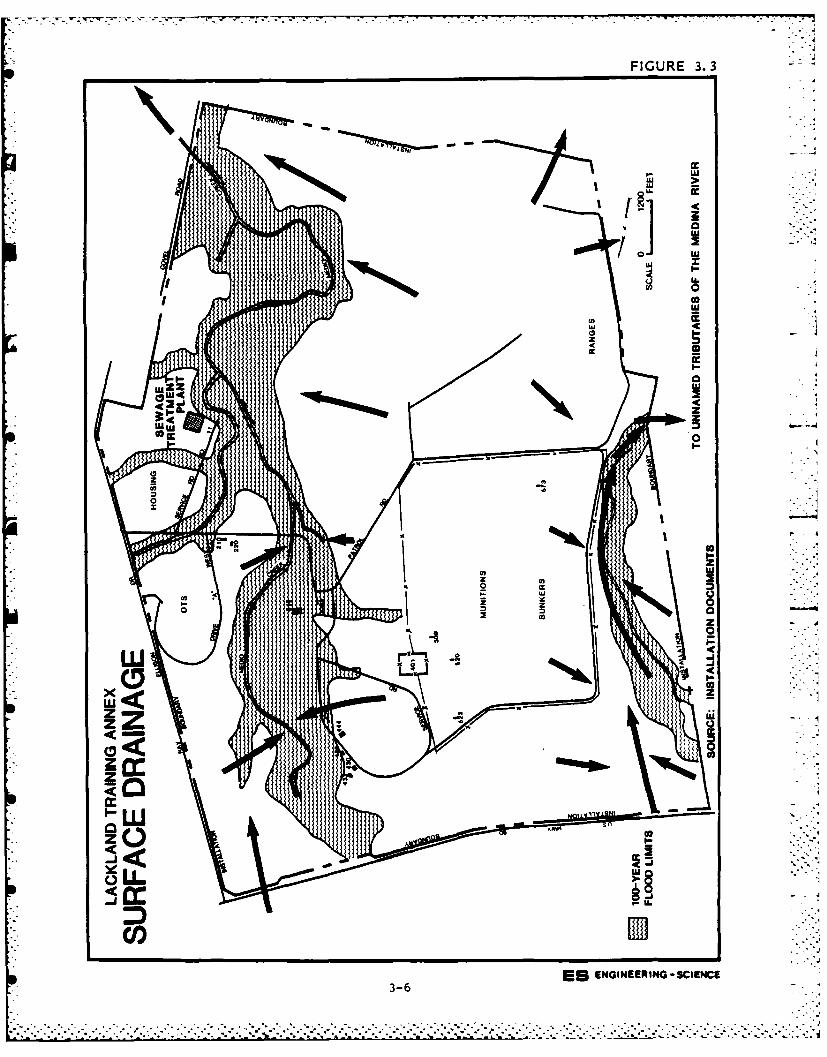
FIGURE 3. 3
* Iczz
0zzc0
z
CID CCINER4-S 0E
3-6,
............................................................
- .. .. .
Drainage from the Medina Lake Recreation Area proceeds in a gener-
ally downslope direction, following local topography to the lake.
Surface drainage from the Oilton Radar Site flows generally to the
west, following local topography toward the Arroyo de Los Angeles and
finally to the Rio Grande River.
No wetlands exist on Lackland AFB or on any of its satellite
facilities.
Surface Soils
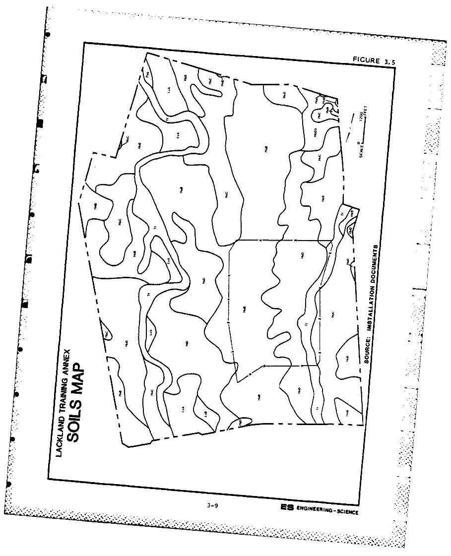
Surface soils of the installation and training annex areas have
been studied by the USDA, Soil Conservation Service (1966) and by McIn-
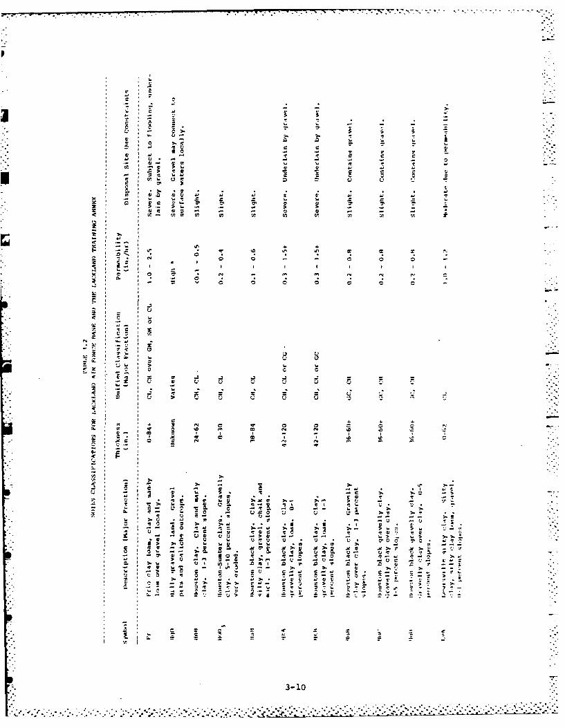
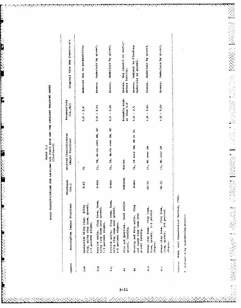
tosh and Behm (1967). Eighteen soil types have been mapped within
installation and annex boundaries, which are depicted in Figure 3.4 and
3.5. The individual soil types are described in Table 3.2. Base soils
are typically alluvial, predominantly poorly drained, fine-grained soils
possessing generally low permeabilities. Surface soils occurring in the
training annex range areas are gravelly materials, in contrast to the
predominantly silty or clayey soils of the study area. Fine-grained
soils usually promote rapid runoff. Gravelly soils tend to reduce
runoff. According to McIntosh and Behm (1967), gravelly clays underlie
surficial soils at depths ranging from two feet below ground surface
along the golf course hillsides to ten feet along the upland areas. The
average thickness of the gravelly clay layer is reported to be five feet
with local variations. Installation surface soils are underlain by
older alluvium. The alluvium is known to vary in thickness from 23 feet
at Kelly AFB Well 1-61 to 60 feet at Kelly AFB Well 1-97.
The surface soils of Hondo and Castroville Airfields are predomi-
nantly the Knippa-Mercedes-Castroville Association. These soils are
deep calcareous clays and loams with varying amounts of silt, sand and
gravel present. This association has formed on nearly level to gently
sloping outwash plains and old stream terraces. Permeabilities and
runoff potentials tend to be slow and the erosion hazard is reported to
be slight (from USDA, SCS, 1977).
Soils of the Medina Lake Recreation Area are composed of the
Tarrant-Real-Brackett Association. These are shallow loamy, gravelly
loamy and cobbly clayey calcareous soils occurring on sloping, undul-
ating and steep surfaces. Limestone bedrock may outcrop locally. Soils
3-7
.......................................
~..................
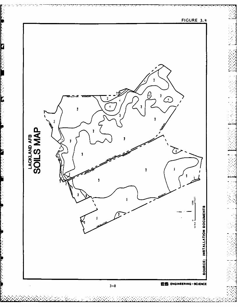
FIGURE 3.4
00
CO
4 0
0
z
0
3-8 E ENGIEERIN - SI-C
7-
~0
114
x PC-J
< -7
CO:
-7 T.
cr WU w W t
V U
I~ ~~~ C~~ ~ 1C) U-
:0. u4 .
-V11 ~ ' 4 41 0
't .V) :I, 4)
301
1kw S w .
3. 43 11 3- el3
43 3 LM, L
• ,..
z I
21 C : 44
3 0 - - ~ 9 0 U3 - - 3
.k. . 4 3 3, ,
43 . ' t- 3 ..'.,~
I - I C 44=) ,. C ",C.
.: 3 - 0 - -
>. l, e . .
=e v
S . . . -"-11
3.3 3 3.. 3.3. -3- .- 3
2,.-. 3 31 41 4 4
J.2o . o
,3 o4 + = 3 4 . . . o . . - . .
tend to be slowly to moderately permeable and runoff is rapid (USDA,
SCS, 1977).
Soils present at the Oilton Radar Site consist primarily of the
Cuevitas-Randado Association. These materials are typically thin sandy
clay loams formed over flat to gently rolling lands with local depres-
sions developing as a result of karst (solution and collapse structures)
terrain. They are usually underlain by white indurated caliche. The
infiltration rates of these soils ranges from slow in zones where the
soil column has developed to maturity to very high where the soil column
is thin and overlies local fracture and solution (sink holes, collapse
structures) cavities. Runoff tends to be slow due to the generally
level nature of the land surface (USDA, SCS, 1984a and Kier, at al.,
1977).
GEOLOGY
The geology of the San Antonio area has been reported by Sellards,
et al. (1932, reprinted 1981), Arnow (1959 and 1963), McIntosh and Behm
(1967) and the Texas Bureau of Economic Geology (1976 and 1983), among
others. A brief review of the published information has been summarized
in support of this investigation.
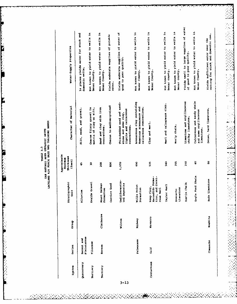
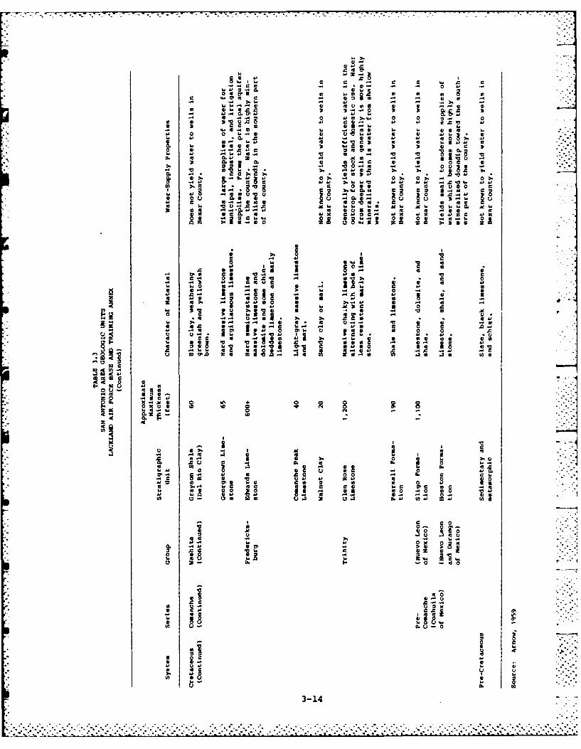
Stratigraphy
Geologic units ranging in age from Cretaceous to Quaternary have
been described in the San Antonio area and are presented as Table 3.3.
The lithologies of these units include unconsolidated materials and
sedimentary rocks.
Distribution
The area of significant geologic units relevant to this study are
mapped as Figure 3.6, which has been modified from the work of Arnow
(1959 and 1963) and McIntosh and Behm (1967). Generally, the upper
geology of Lackland Air Force Base and the Lackland Training Annex is
dominated by thick sections of marls of the Navarro and Taylor Groups.
Geologic section A-A' is presented as Figure 3.7.
Structure
Lackland Air Force Base occupies a position within the tectoni-
cally significant Balcones Fault Zone. Normal faulting in this area has
been attributed to the settlement of the Gulf of Mexico geosyncline,
3-12
S .. 5. *. *.. . - ...-. ,* - .. S . . . .
0 19
AM -i 41 CAi- -
0 042
o1 41 41 41 4 41 41 6; 4) U>. 41 L,
'4~a .4 z 9 0. 0> 0 ~ 3 I0 Z V OZ 0. V VV C
WV -0 1 41 . l. 0 -
04 V ri 44 41 4 0i
3t 41 c 4) At W O* Ad 0
cn --0> 0> '4 "4 > 0 > 0> 0 0 4 0> SO
0 30 41 zz 0 U
V 0 c f 0
r) 0- .04. 0430 -). -C 04. 1 410
04 4 c4 >00 Z0 4) 2 >. 30
0 0 o 00t. 4 C0 a . 0 4)A
Cj * .. 0 41 C 0V C 41c) (1 A;1
'41 4 10 m aC we so0 C
%w 0) 414 0 04O1 -0' 04 v 4) I.0100' )
0~~~~~~ s4 01V J 1441'4 ) 4
0 z 10 be -CO . .4 04
oc C1UU ' 4) 4) '4 4)1 4
-, -- j 00 .0 u.
C .x 0 V)V .
U '4'4 VO 0 410 -
go CCC 4EC )'
6;,)
.4 , 0
-~0 a).M1 44 4 0 4 49 0 0U) 1. -1 44E -
2~ 0'0 IWO r
04)44 C 4 4 49 '
z 3
4141 4) 4
(n 06 4) to,.0
-4 .
En 00 4) 1 44. .4u
0. 4) U 4) C-13 '
4j~
41
3, 41 4.c
CC i 0 04
w44.4 41 41A41 4
. C 0 04~l. 0 0 c.. 0
449 P 0 0 44 44 D1.4 4 1 41 44 * 4
0. -0. diC 4 41 V4 4 41 c 41 C i 444~~ 41 c~44. 0 410 5 '
0.1 0. 41 41 04 to 4 - 0A. 0.441x A 0 - *41 -41 O 44x1 jI
Cw -w owo. 44 0 =0 00 %4 = 0 = 0
.C0 0 -0.4-
444 441 C4 4 '44
-C C 4144-4 C C 411 4
Z44 4 041 4
411
z CCV1 0 1 0 0 05
41.44 A4 41 Ci0 4 C4 1~ 5 4
C1 414 0I o 0 feC.44 Iwo41 CC 1 54 14 441'
e 9 -0 lal
4 C03 !0 41.40
0 44 0 0 %VC
44 . C C.-C~ CL n .41 .4 n
00
041
K.*1 0 0 0 0 ID44C.4 01 go N -
FA2.. .3 2 I2C V 4 i0
c 0.
3 3 0 110~ 410 w4*
w V40 0 .4 0% Ce ?.
C a4 00 4
44D 06 U0 0004 b
5...-4C~ ~ 04 4r4
41 ~ 4 .1 '4 C 0 4 1 0 4C a4 4C C U C 04 4 . C 44
44 ~ ~ ~ ~ ~ ~ ~ ~ C MO0 ~ 11 .4 411C 4 1
44 '544 3-14 4 - 44 04 44
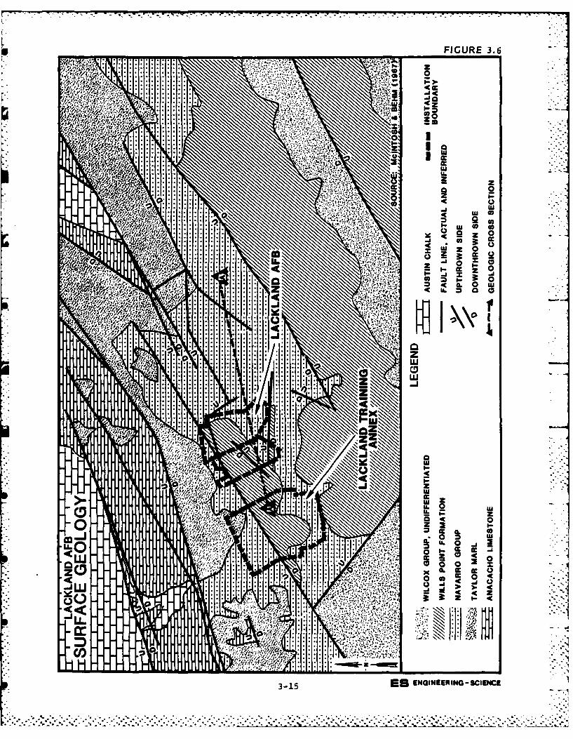
FIGURE 3.6
4'0
&*r~....
.. . . cc
LK Z
f . ':mo. ~ liz 0
3 15Es NGINERIO-SCEHC02 Z) A 3:1
______________________ 4L -0--- w.- . __
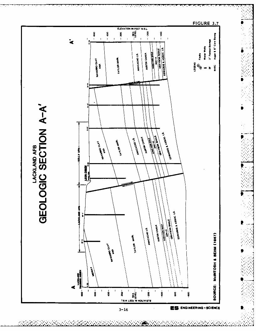
FIGURE 3.7ELEVATION IN FEET M.S.I..
-Ju
z
CID
U I
3-16
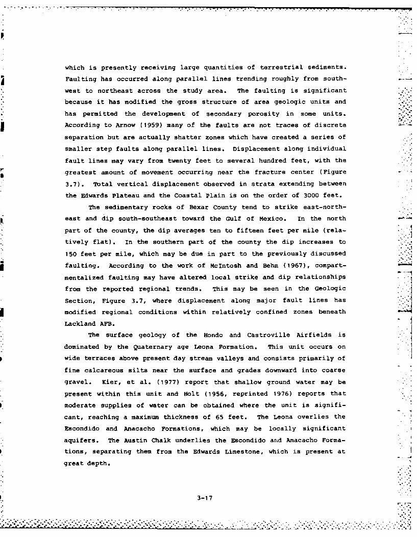
which is presently receiving large quantities of terrestrial sediments.
Faulting has occurred along parallel lines trending roughly from south-
west to northeast across the study area. The faulting is significant
because it has modified the gross structure of area geologic units and
has permitted the development of secondary porosity in some units.
According to Arnow (1959) many of the faults are not traces of discrete
separation but are actually shatter zones which have created a series of
smaller step faults along parallel lines. Displacement along individual
fault lines may vary from twenty feet to several hundred feet, with the
greatest amount of movement occurring near the fracture center (Figure
3.7). Total vertical displacement observed in strata extending between
the Edwards Plateau and the Coastal Plain is on the order of 3000 feet.
The sedimentary rocks of Bexar County tend to strike east-north-
east and dip south-southeast toward the Gulf of Mexico. In the north
part of the county, the dip averages ten to fifteen feet per mile (rela-
tively flat). In the southern part of the county the dip increases to
150 feet per mile, which may be due in part to the previously discussedfaulting. According to the work of McIntosh and Behm (1967), compart- -
mentalized faulting may have altered local strike and dip relationships
from the reported regional trends. This may be seen in the Geologic
Section, Figure 3.7, where displacement along major fault lines hasmodified regional conditions within relatively confined zones beneath
Lackland AFB.
The surface geology of the Hondo and Castroville Airfields is
dominated by the Quaternary age Leona Formation. This unit occurs on
wide terraces above present day stream valleys and consists primarily of
fine calcareous silts near the surface and grades downward into coarse
gravel. Kier, et al. (1977) report that shallow ground water may be
present within this unit and Holt (1956, reprinted 1976) reports that
moderate supplies of water can be obtained where the unit is signifi-
cant, reaching a maximum thickness of 65 feet. The Leona overlies the
Escondido and Anacacho Formations, which may be locally significant
aquifers. The Austin Chalk underlies the Escondido and Anacacho Forma-
tions, separating them from the Edwards Limestone, which is present at
great depth.
3-17
The geology of the Medina Lake area is dominated by the outcrops
of the Edwards Limestone and the Glen Rose Formation limestone and
dolomite. In the geologic column, the Glen Rose underlies the Edwards.
This portion of the study area is significant as the Edwards Aquifer
receives much of its recharge in its outcrop zone.
The geology of the Oilton Radar Site is dominated by the Pliocene
Goliad Formation, a 300-foot sequence of clay, marl, caliche, sand,
sandstone, limestone and conglomerate. Locally, the unit is iell bed-
ded.
HYDROLOGY
Ground-water hydrology of the Lackland Air Force Base-San Antonio
area has been reported by Arnow (1959, 1963), Garza (1962), Pearson et
al. (1975), Baker and Wall (1976), Maclay and Small (1976), USBR (1978),
Metcalf and Eddy, Inc. (1979), Muller and Price (1979), Marquardt and
Elder (1979), Maclay et al. (1980), and Maclay et al. (1981). Addition-
al information has been obtained from interviews with officials of the
U.S. Geological Survey Water Resources division and the Edwards Under-
ground Water District. Information describing shallow aquifer condi-
tions was obtained from the interviews and from McIntosh and Behm
(1967).
Edwards (Balcones Fault Zone) Aquifer
Lackland AFB lies within the limits of the Edwards (Balcones Fault
Zone) Aquifer, which is defined as a "sole source" aquifer by the U.S.
EPA. In 1959, the Texas Legislature created the Edwards Underground
Water District to provide for the systematic planning and protection of
subsurface water resources derived from the Edwards Aquifer. Regulatory
authority is governed by the Texas Water Code Section II, Chapters
156.20.01.001-.019 and extends into the recharge zone (outcrop area)
located north of the reservoir zone.
The area underlain by the Edwards Aquifer sweeps an arc extending
from Kinney County to the west, to Hays County on the east aquifer
boundary. This area is approximately 175 miles long and varies in width
from 5 to 30 miles. The west, north and east aquifer boundaries are
defined geologically where hydrogeologic units crop out forming the
generally acknowledged recharge zone or where ground-water divides
3-18
.......................... ..... . . . .." ' % -. ,. ., '- '. "° % ." 2. "*". ", '- "- "° 'o "° . °' . ,' , ' -° ', -' " '. ," °" -" ," ," -" -" ° " '''' ' '' ''. -- '
exist. The south aquifer boundary is arbitrarily defined as the "bad
water line" where total dissolved solids concentrations exceed 1,000
milligrams per liter (mg/L) . The aquifer (reservoir) area and its
associated recharge zone are presented in Figure 3.8.
The Edwards Aquifer consists of three hydrogeologic units which
are known to be hydraulically continuous: the Georgetown Limestone, the
Edwards Limestone and the Comanche Peak Limestone. The Limestone units
are described as being thin to massive-bedded, nodules, cherty, gyp-
seous, argillaceous white to gray limestone and dolomite. The rock is
characterized by an extensively honeycombed, cavernous structure created
by solution channeling over a wide area.
At Lackland AFB, the Edwards Aquifer lies some 1,490 feet below
ground surface. The well log depicted in Figure 3.9, illustrates hydro-
geologic units encountered at Lackland Well No. 3 which is typical of
the study area. installation well logs indicate a typical aquifer
thickness of 540 feet in the study area.
The Edwards Aquifer is confined at its base by the Glen Rose
Formation and at its upper surface by the Del Rio clay or correlative
units. Water is contained in the Edwards under confined (artesian)
conditions.
The Edwards is recharged principally by the downward percolationof surface waters from streams traversing the area of outcrop and by
precipitation infiltration in this same zone. Figure 3.10 depicts the
recharge area in a generalized cross-section. In areas where streams
cross the aquifer area of outcrop, numerous large solution channels have
been observed (Arnow, 1959). Similar large solution channels have been
noted on driller's well logs in the reservoir zone several miles to the
south. Once water has entered the Edwards, it moves rapidly downdip
(Maclay, 1981) principally in solution channels such as those shown in
the hypothetical flow diagram presented as Figure 3.11. Ground-water
flow directions are both to the south (downdip along formation grad-
ients) and to the east - northeast paralleling the fault system and
according to prevailing hydraulic gradients (Pearson, et al, 1975).
Figure 3.12 depicts water levels within the Edwards as of July, 1974
with approximate ground-water flow directions. It should be noted here
that local variations in flow directions may occur.
3-19
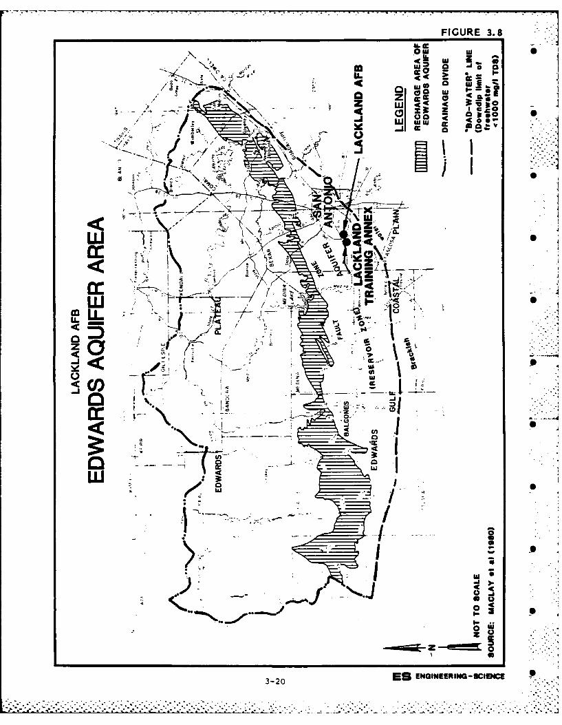
FIGURE 3.8
OwlLLI Us
.. >J U. C C C 3:B0
73 Zg so
to
" ..........
~LL t4
C.I)
LU.
coo
ir6
cl*TI
ujI
.- mai- z 0
3-20ES ENGINEERIN -CICE 5
3-20.
L 7* -.
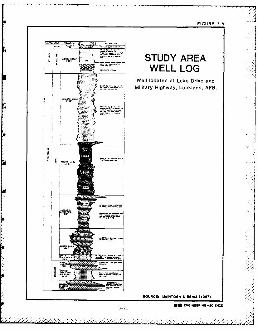
FIGURE 3.9
'SYSTEM SpXELI!!! ORMAT ION ~v A OESCRrPTION
~~M~w~ e~upSTUDY AREA
ZO 3--:::-Y~uvS.,WELL LOGWell located at Luke Drive andMilitary Highway, Lackland, AFB.
14AVARRO GROUP L
I 1 -- 0--L
(3111
SORE:000OH EH 197
3-1 S NINERN-SIEC
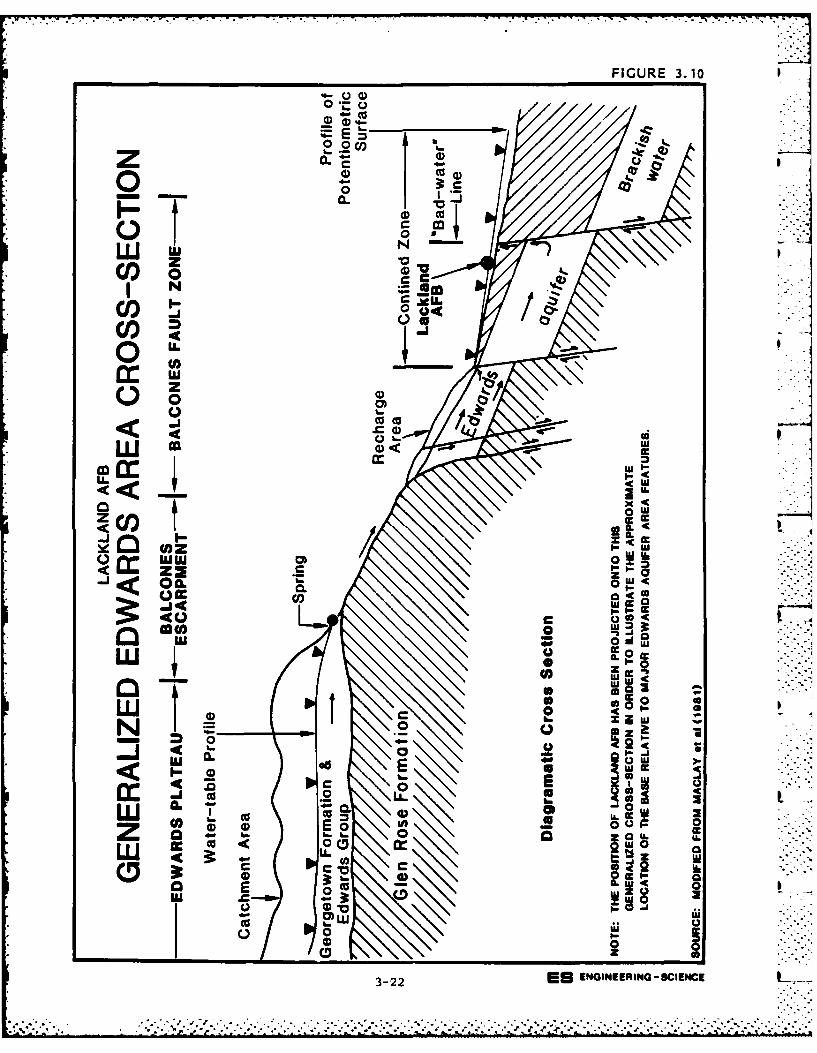
FIGURE 3.10
o Iob .2
zV
jN
U))
14 w* 0
ULJ ccco I,-LLz c
0(0
< - IL 4 .
(ozA
OI 0 0 1& -
o a0 cc
* -o
O 0u
_ z00 22
z0 E3-0E NIERN-CEC
...................-, - . . . .... .-. ...- .-. . . .-u . . . . . . . . . . .
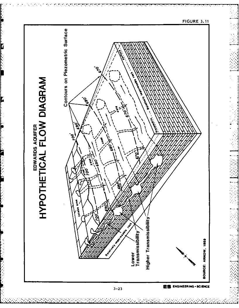
FIGURE 3. 11 w
co
E0
0
0)
0
~LL
~mIV\
wII
I-
00
0
3-23 ES ENGINEERIING-SCIENCE'
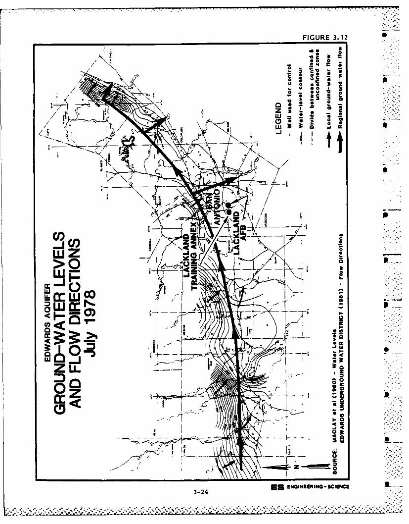
FIGURE 3.12 0
0 ; aI,
0 *@ 0Cc
0ac~30
Z Clowa
wm
ZO Z Cc
.7 II 9
44r -
0
uja
cc0
* r*
LU-
0 Iu
0
3-24ES ENGINEERINGO-SCIENCE
- . S . .. * *t~.3.. . .
- ~~~~~~~~~~~~~~. .-. .°.......... .. ...... r ...-... . ...... .... .. .... ..
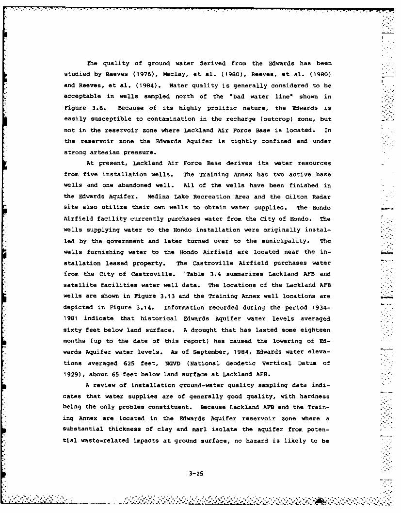
The quality of ground water derived from the Edwards has been
studied by Reeves (1976), Maclay, et al. (1980), Reeves, et al. (1980)
and Reeves, et al. (1984). Water quality is generally considered to be
acceptable in wells sampled north of the "bad water line" shown in
Figure 3.8. Because of its highly prolific nature, the Edwards is
easily susceptible to contamination in the recharge (outcrop) zone, but .
not in the reservoir zone where Lackland Air Force Base is located. In
the reservoir zone the Edwards Aquifer is tightly confined and under
strong artesian pressure.
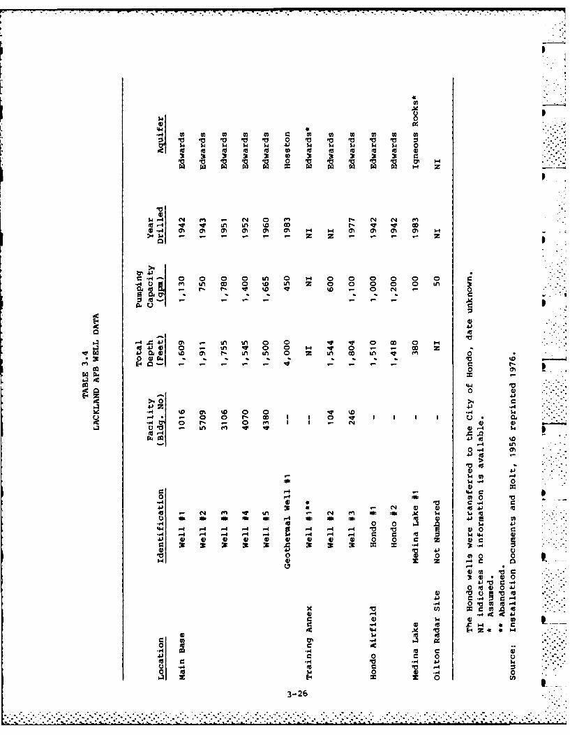
At present, Lackland Air Force Base derives its water resources
from five installation wells. The Training Annex has two active base
wells and one abandoned well. All of the wells have been finished in
the Edwards Aquifer. Medina Lake Recreation Area and the Oilton Radar
site also utilize their own wells to obtain water supplies. The Hondo
Airfield facility currently purchases water from the City of Hondo. The
wells supplying water to the Hondo installation were originally instal-
led by the government and later turned over to the municipality. The
wells furnishing water to the Hondo Airfield are located near the in- -
stallation leased property. The Castroville Airfield purchases water
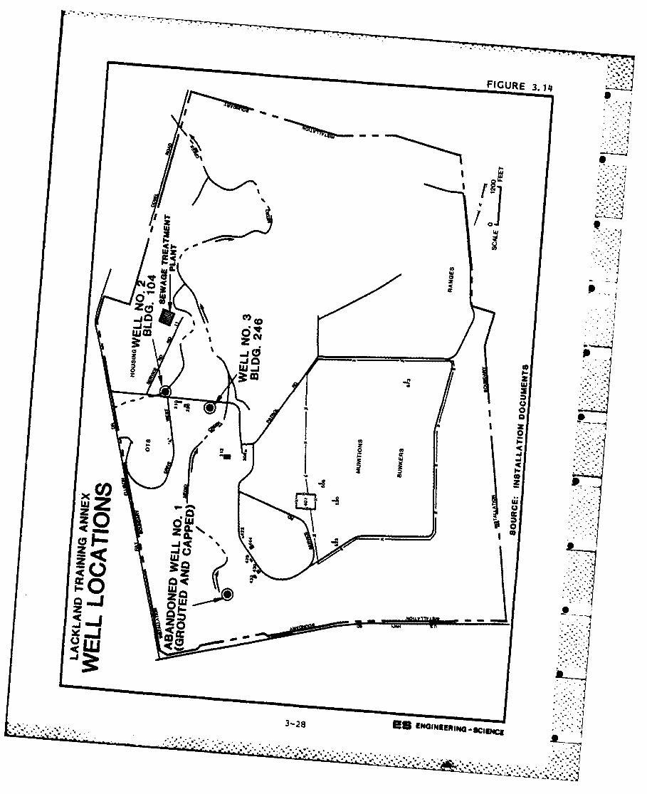
from the City of Castroville. 'Table 3.4 summarizes Lackland AFB and
satellite facilities water well data. The locations of the Lackland AFB
wells are shown in Figure 3.13 and the Training Annex well locations are
depicted in Figure 3.14. Information recorded during the period 1934-
1981 indicate that historical Edwards Aquifer water levels averaged
sixty feet below land surface. A drought that has lasted some eighteen
months (up to the date of this report) has caused the lowering of Ed-
wards Aquifer water levels. As of September, 1984, Edwards water eleva-
tions averaged 625 feet, NGVD (National Geodetic vertical Datum of
1929), about 65 feet below land surface at Lackland AFB.
A review of installation ground-water quality sampling data indi-
cates that water supplies are of generally good quality, with hardness
being the only problem constituent. Because Lackland AFB and the Train-
ing Annex are located in the Edwards Aquifer reservoir zone where a
substantial thickness of clay and marl isolate the aquifer from poten-
tial waste-related impacts at ground surface, no hazard is likely to be
3-25
°o ... . . . . .
-- '-- _.t z z .. _.'_ : .. : ' L-' •. 4 i - ". .".. . .".. . . . .".. . . .. . . .-.. . . . .-. .".. .•. ."...". .".-... .".
'0 V0 V 0 10 a0 ' '0 V0 Vw 4 $4 $ 4 41 w $4 $4 $ $
'0 ' ' 0 0 0 V0 '0 ' V '0 0 0trrz~~~ wa ra z ~ 2 z z H 2
O4.- ' iAN 4 q0 4 a% 0 0 0 0% 0 H 0 % %
~e41in4 0 nI 0 0 0V 0 0 0 C
to 41 0 %O LA V 0 0 V 0 - 0 0 i- NL V 0 4% - 0 (
im 44 -- -
44E-4
-44 - I 0 0 r. CD 0 01410 0 -, -f 4 0 4 0 -
V1. -~ 0% N U 4 1) ~ UO 4. * * 0 0E4 0'- v it 4- - -
-
00) 0
41ft 41 a 0 . -.-4 to % . 0 0 4 I
C.) 41 W 0 0 z ' gg g u * 0
.0 0 m~ 0 - (4'- .0.0c
-4 L
414
C 4(A to -4
C4 'A4 O- 41
4E-4 Z 0 C.t. C.
- m 04 0.. i
0 40
0~ .00
3-26 -
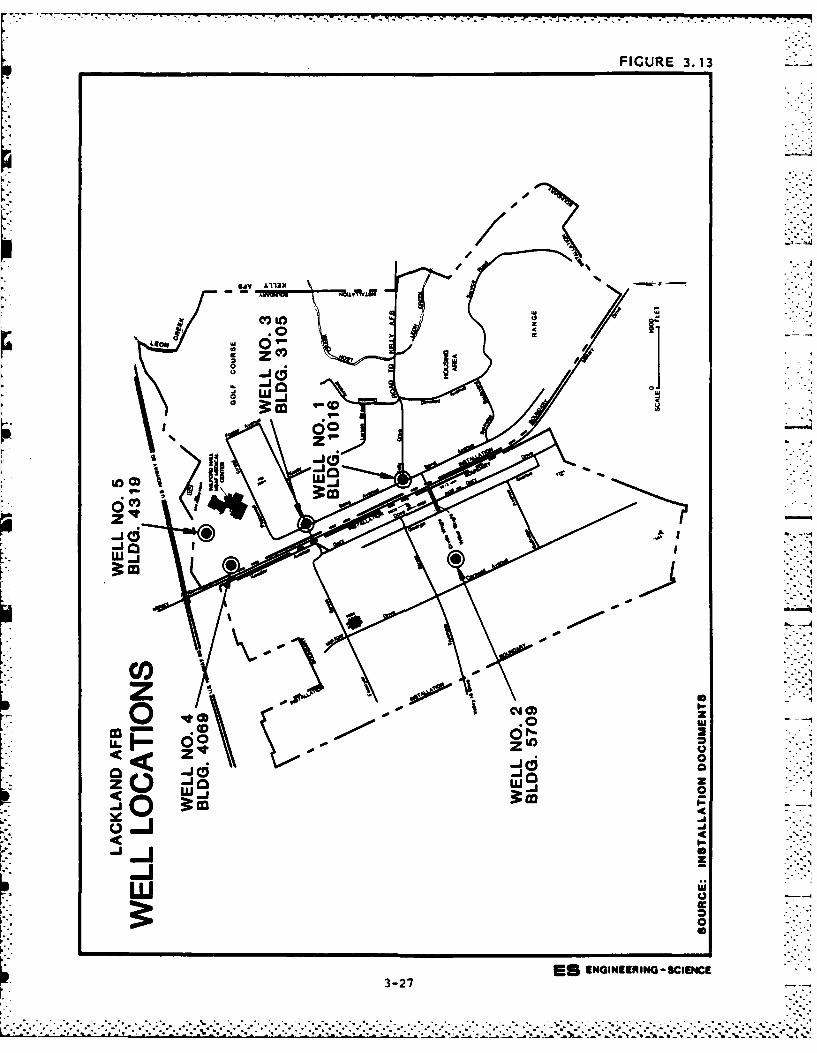
FIGURE 3.13
UV A13/
0 w _ ca
co- 0
W _w
z 00
zK -5----
3-2Omm
IGURE 3.1
021
39p
xI
w Zz 0 CI.3 qNIURSEW.,.z..-i (.)
II
posed to the primary regional aquifer. A potential threat does exist,
however, due to the corrosion of existing well casings or the improper
abandonment of inactive water wells. When a well is constructed, shal-
low geologic units are penetrated and sealed off from the lower zones
(such as the Edwards) where the well is designed to obtain water. jDecomposition of the cement grout used to backfill the annular space
between the casing and the borehole or corrosion of the metal casing
will eventually penetrate these layers of protection and permit the
interchange of flow between shallow and deep water-bearing zones. This
effect may allow contaminants to enter the regional aquifer. Such a - -"
situation was documented in November, 1983 when it was determined that
gasoline from a leaking underground storage tank entered the Edwards
Aquifer via the corroded casing of an inactive well located about twenty
miles from Lackland AFB in northeast San Antonio. The leaking well
casing was subjected to television inspection which confirmed the gaso-
line migration (Bader, 1984). In order to avoid this problem, active
wells should be inspected periodically to insure that casing integrity
is being maintained and water levels should be monitored frequently. A
sudden change in well water levels may indicate that the casing has been
breached. Well No. 1 at Lackland TA was abandoned due to a leaky cas-
ing. The well was grouted and capped.
Shallow Aquifer Zones
Coarse-grained alluvium deposited by existing or now abandoned
stream channels exists at shallow depths throughout much of the study
area. The granular alluvium typically begins at depths in the range of
two to ten feet below present land surface and varies in thickness,
averaging five feet. Ground water contained in the alluvium may be
present at depths below ground surface in the range of five to fifteen
feet, and is usually absent below 25 feet. This condition has been
interpreted by McIntosh and Behm (1967) to indicate that a perched water
table exists in the general study area. The perched water table system ...
is probably recharged directly by precipitation and/or where the granu-
lar materials are intersected by the courses of surface streams. Flow
directions, persistence and lateral limits of this perched system are
uncertain. It is suggested that shallow aquifer zones adjacent to local
streams are recharged during high flow periods and discharge to the
3-29
- U . - . . . . ..
_ . .. . . . .. . .€ -_. U_.: _ . . . . . . ..1 . . . .?. ..... .... - . . , . . : .-
streams during dry periods, providing base flow to the nearby surface
waters.
A ground-water quality monitoring program conducted at the Kelly
AFB sludge lagoon adjacent to Leon Creek, apparently encountered a
shallow aquifer at depths below present ground surface ranging from
13.25 feet to 14.16 feet, as measured in four of seven monitoring wells.
Presumably, coarse-grained alluvium deposited along the breadth of Leon
Creek's floodway is the water-bearing stratum, and is, therefore, pro-
bably in periodic communication with base surface waters.
Surface Water Quality
The Texas Department of Water Resources has regulatory responsi-
bility for the maintenance of water quality in the San Antonio area.
The applicable Surface Water Quality Standards for general surface
waters and Leon Creek are contained in Appendix 0. Leon Creek and Medio
Creek within Lackland AFB and Lackland TA are classified for contact
recreation, non-contact recreation, propagation of fish and wildlife,
and domestic raw water supply by the Texas Department of Water Re-
sources.
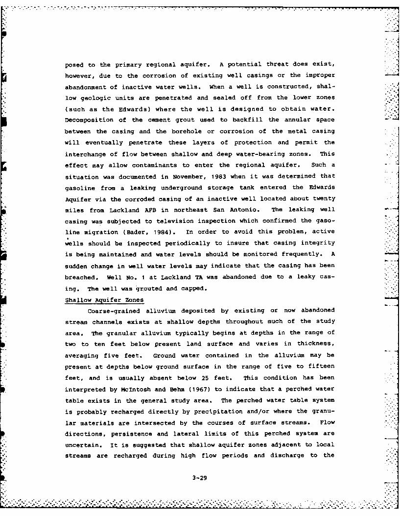
Lackland AF conducts routine surface water monitoring activities
at locations where Leon and Medio Creeks cross the installations. The
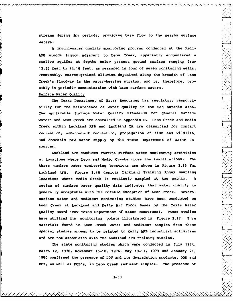
three surface water monitoring locations are shown in Figure 3.15 for
Lackland AFB. Figure 3.16 depicts Lackland Training Annex sampling
locations where Medio Creek is routinely sampled at two points. A
review of surface water quality data indicates that water quality is
generally acceptable with the notable exception of Leon Creek. Several
surface water and sediment monitoring studies have been conducted on
Leon Creek at Lackland and Kelly Air Force Bases by the Texas Water
Quality Board (now Texas Department of Water Resources). These studies
have utilized the monitoring points illustrated in Figure 3.17. The
materials found in Leon Creek water and sediment samples from these
special studies appear to be related to Kelly AFB industrial activities
and are not associated with the Lackland AFB training mission.
The state monitoring studies which were conducted in July 1974,
March 12, 1976, November 15-18, 1976, May 10-11, 1979 and January 21,
1980 confirmed the presence of DDT and its degradation products, ODD and
DOE, as well as PCB's, in Leon Creek sediment samples. The presence of
3-30 L
.... ......... o... ... ................"."," ." . . *--".' . **.'.'.".' . %''''"""•""''""""''.,_..+_. .. ,_.2 '' '' .-. .- 2 ''i'-'.2'% . _J'' "% _: '-',_J ._.
FIGURE 3.15
Cow w
c«U. ULLU
zz
0 0
a.z zCO JU f
~Eb, *
z
0
0
ES ENGINEERING -SCIENCE3-31
FIGURE 3.16
00
C'CC
m z0 - I
22
'zx 04w -- a
izz2
10
~LL
P3-32 ES ENGINEERING -SCIENCE
7 . . .
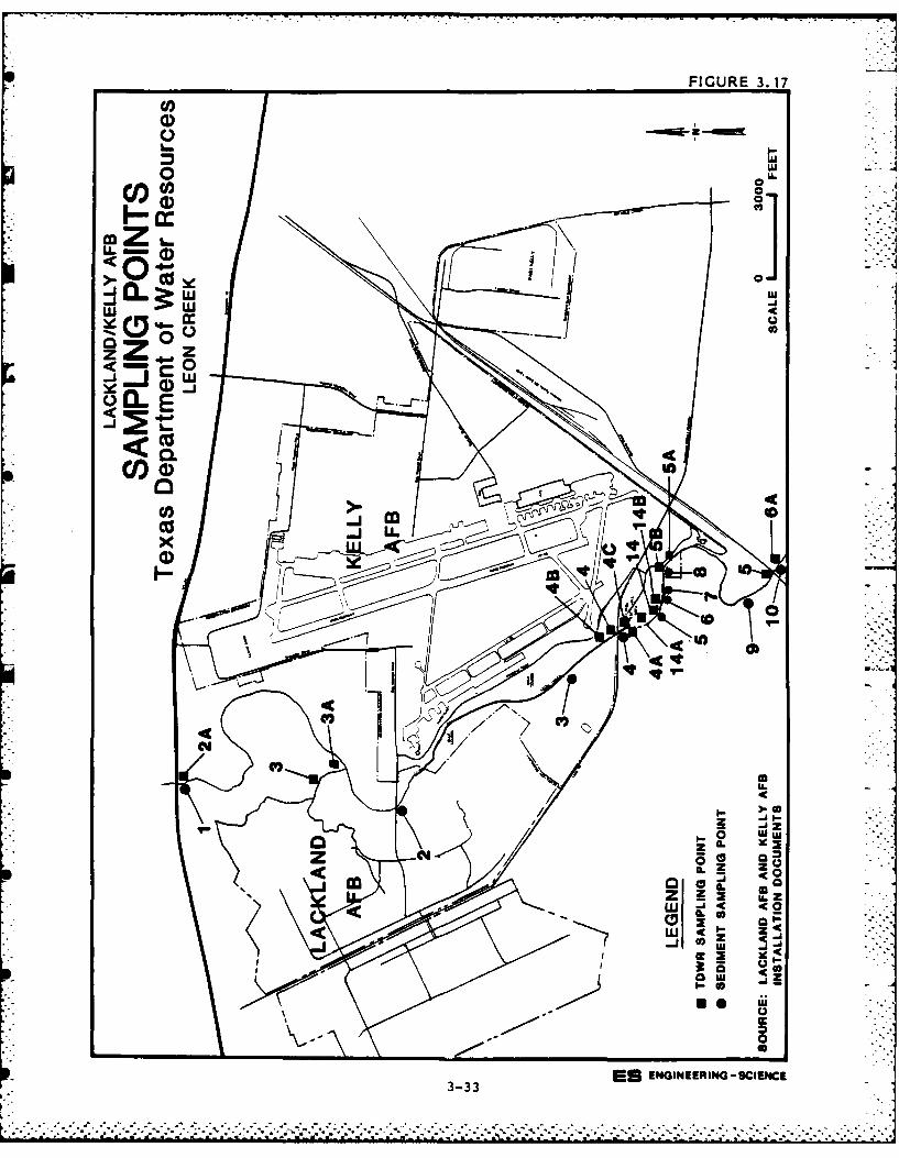
FIGURE 3.17
0
CIS-.j w
o w
00r0)
_i~j w
ESL ENIERN-CEC_j 3-33
cc
diethylhe !1 phthalate was found in sediment samples taken from Station
14 (discharge point 001). However, this compound was detected at only
one sample point. In addition, heavy metal concentrations were noted at
various sediment sampling locations along Kelly AFB, particularly at
Station 14. Sediment pesticide analyses for sampling stations at Kelly
AFB on May 10, 1979, are illustrated in Appendix D (Table D.3). Sedi-
ment heavy metals analyses at the same stations are illustrated in
Appendix D (Table D.3).
In addition to Lackland and Kelly Air Force Bases, several other
facilities may impact the quality of local surface waters, especially
Leon Creek. A municipal wastewater treatment plant discharges to Leon
Creek north (upstream) of Lackland AFB. Two municipal landfills are
located adjacent to Lackland AFB. One landfill is situated north of the
installation and is adjacent to Leon Creek. The second landfill is
located south of Lackland Training Annex, also near Leon Creek.
THREATENED OR ENDANGERED SPECIES
No threatened or endangered species of plants or animals are known
to exist on Lackland Air Force Base or on any of its satellite facili-
ties.
ENVIRONMENTAL SUMMARY
Geographic, geologic and hydrologic data evaluated for this study
indicate the following:
o The sole source aquifer, the Edwards, underlies Lackland AFB
and Lackland Training Annex at depths of 1,000 feet or deeper.
o Lackland AFB and its Training Annex lie within the reservoir
area and not the recharge zone of the Edwards Aquifer.
o The Edwards Aquifer functions under artesian conditions and is
sealed from the ground surface by substantial sequences of
clay, marl and sandstone.
o A shallow water table (unconfined) aquifer has been shown to
exist on base and is probably in communication with base and
annex surface waters (Medio Creek, Leon Creek). The full
extent of this aquifer is unknown.
3-34
• ,,, .°, . , , -.. •... . ..°'* L _- " 2-,--- ,' "-,' "i 'J. . . . . . . . . . . .... . ..""". ." " •"'. . . . •. . . . . . ... .
o Leon Creek traverses Lackland AFB and Medio Creek passes
through Lackland TA in a north to south direction.
o Base surficial soils are predominantly silts or clays that
exhibit low permeabilities. More permeable, coarser-grained -
soils are present at ground surface in zones proximate to Medio
and Leon Creeks.
o Annual net precipitation for the area is minus 30 inches. This
condition reduces the amount of leachate generation resulting
from precipitation at landfills located on Lackland AFB and
Lackland Training Annex.
o No wetlands exist at Lackland AFB or at any satellite facili-
ties.
o Natural populations of either threatened or endangered plants
or animals do not exist on the base or its satellite facili-
ties.
o A municipal wastewater treatment plant discharges to Leon Creek
north of Lackland AFB.
o Two city landfills are located adjacent to Lackland AFB. One
landfill is located north of the base and adjacent to Leon
Creek. The second landfill is located just south of Lackland
Training Annex near Leon Creek.o The Leon Creek sediment analyses have shown heavy metal, pesti-
cide and herbicide contamination associated with nearby Kelly
AFB. These impacts are probably not connected to Lackland AFB
or its training mission.
A potential does exist for the generation and migration of waste
contaminants into and through the shallow aquifer zone. Wastes disposed
in areas adjacent to Leon Creek or Medio Creek have been placed in the
unsaturated portion of this aquifer. The aquifer is present at shallow
depths and is recharged directly by precipitation and/or by communica-
tion with the streams. Waste migration would reasonably be expected to
move through the shallow aquifer and enter Medio or Leon Creeks as part
of the base flow during dry periods.
From these major points it may be concluded that the potential for
the generation and subsequent migration of contaminants originating from
3-35
. . . . .. . . . . . . . . . . . . . . .. IiI_ m. . . . ..L . . .... . . . . .. . [., . ," , , ,
. . ° . .
past waste disposal sites to the deep (Edwards) aquifer is not likely
unless migrating wastes encounter an improperly abandoned well and
follow deteriorating casing materials downward into the potable water
zone. The actual movement of contaminants into an artesian aquifer
would be governed by the hydrochemical properties of the individual
material.
3-36
I-_
3-36°
* . . : . ..- :'-'-i-
SECTION 4
FINDINGS
This section summarizes hazardous waste generated by installation
activities, identifies disposal sites located on base, and evaluates the
potential for environmental contamination. Past waste generation and
disposal methods were reviewed to assess hazardous waste management atLackland Air force Base and associated facilities.
SATELLITE ANNEXES REVIEW
Lackland Training Annex is a major part of the Lackland AFB mis-
sion. Waste generation and disposal activities at this annex are dis-
cussed later in this section with the base.
The Hondo Annex lease includes a combination hangar/classroom/ad-
ministrative building, parking lot, apron parking area for 75 airplanes,
and use of runways and access roads. This facility is operated by the
OTS for flight screening. T-41 aircraft are used at Hondo. All major
maintenance and painting of aircraft are done off-site by contract.
Touch-up painting is done at Hondo as is minor aircraft maintenance such
as motor oil changes and small parts cleaning. The annual liquid waste
quantities generated presently are approximately 520 gallons of oil and
430 gallons of solvent. All waste oils and solvent (Varsol) are stored
on site for subsequent hauling off of the installation site by contract.Minor quantities of paint and thinner are either poured down the sani- 711tary sewer drains or placed in dumpsters. All solid wastes including
oily rags, paint residuals in rags and cans, etc. are placed in dump-
sters and landfilled off-site.
The Hondo Airfield Annex is supplied water by the City of Hondo;
similarly all wastewater is discharged to the city sanitary sewer sys-
tem. Two oil-water separators are provided for aircraft washracks. The
waste-water is discharged to the sanitary sewer system and the oil is
hauled off of the installation by a contractor.
4-1
-, "- .
Three above-ground tanks exist at Hondo for diesel fuel, Mogas and
solvent. One mobile Avgas tank trailer is also used. There are no
known leaks or spills from these facilities.
In summary, the leased Hondo Annex has waste generation activities
but wastes have historically been hauled or transported for disposal off
of the installation.
The USAF has had only indirect involvement with wastes gener-
ated by Gary Aircraft Corporation (also a tenant at Hondo Airfield). At
one time Gary Aircraft Corporation was under contract to strip and paint
USAF T-38 Aircraft. Hazardous paint stripper and cleaning residues were
stored in drums. Deterioration of drums prior to disposal caused leak-
age of wastes onto Gary Aircraft ground and subsequent enforcement
action by State officials. The USAF was involved in the general agree-
ment on disposal of those wastes.
The Castroville Airfield Annex has been leased for emergency land-
ings only. It has primarily been designed for use by aircraft from
Randolph AFB, however, the number of times Castroville has been used is
reported to be minimal. No facilities are provided for the Air Force;
only the runways and a small plot of land to roll a plane onto in case
of an emergency are the present uses of this site. This facility has
had no history of waste generation or disposal.
Medina Lake Recreation Area has been leased for only a few years.
Facilities include a main pavilion, two dwellings, picnic shelters, and
a marina. Water is supplied by a well. Wastes are removed from the
site by a contractor. Two above ground fuel tanks exist for gasoline
and gas/oil mixture. No spills, leaks, or waste disposal have occurred
on the site.
The Oilton facility is a radar site used by TAC. Facilities in-
clude two antennas, a well, septic tank and tile field, below ground
diesel fuel tank and buildings shared with the FAA. All solid and other
wastes are hauled off the site by contract. There are no reported
spills, leaks or waste disposal on the installation.
BASE HAZARDOUS WASTE ACTIVITY REVIEW
A review was made of past and present main base and training annex
activities that resulted in the generation and disposal of hazardous
4-2
............-.-. ....... ........ ... ...........
- .-. ....
wastes. Information to support this review was obtained from files,
records, facility inspections and interviews with past and present base
employees.
It is noted that file data and interviews did not enable deter-
mination of waste handling activities prior to about 1945 at Lackland
AFB. From the historical descriptions of training activities at
Lackland AFB prior to 1945, it is believed that the generation of ha-
zardous materials was small. In addition, many of the currently known
hazardous chemicals were developed during and after World War II. At
the Lackland Training Annex, Air Force operations did not begin until
1966 and waste handling activities are traced back to that time. Prior
to USAF operations at this site, AEC operated a weapons maintenance and
storage facility.
Hazardous waste sources at Lackland AFB and the Lackland Training
Annex are grouped into the following: L
o Industrial Operations (Shops)
o Waste Accumulation and Storage Areas
o Fuels Management
o Spills and Leaks
O Pesticide Utilization -
o Fire Protection Training
The following discussion addresses only those wastes generated (or
stored) on Lackland AFB or Lackland Training Annex which are either
hazardous or potentially hazardous. In this discussion a hazardous
substance is defined by the Comprehensive Environmental Response Com-
pensation and Liability Act of 1980 (CERCLA). Waste oils and liquid
fuels are also included as a hazardous substance because they are of
concern to Air Force operations. A potentially hazardous waste is one
which is suspected of being hazardous, although insufficient data are
available to fully characterize the material.
Industrial Operations (Shops)
The industrial operations at Lackland AFB and Lackland Training
Annex can be divided into five main operating units as follows:
4-3
-7-~~~ -"7-777--"-
o 3700th Air Base Group
o DOD Dog Center
o Resource Management
o Wilford Hall Medical Center
o Lackland Training Annex (Medina)
Various branches and offices exist within each operating unit, many
of which use hazardous materials and/or generate hazardous wastes. A
review was made of the Bioenvironmental Engineering Services (BES) shop
files to identify those shops which handle hazardous wastes. The re-
sults of this file review are presented in Appendix E - Master List of
Shops.
For those shops that were identified as handling hazardous material
or generating hazardous waste, personnel were interviewed to obtain
required information. The information obtained from base interviews,
base records and facilities inspection were used to establish a time
line of disposal methods for major wastes generated at each shop. The
information presented in Table 4.1 shows shop and building number, shop
wastes or materials used, current quantities of wastes or materials
used, and disposal methods.
Most wastes are generated by support functions (vehicle mainte-
nance, weapons maintenance, etc.) and disposal is generally managed
through the Defense Property Disposal Office (DPDO). The sanitary sewer
is used to dispose of a number of minor waste liquid streams. In two
instances, disposal of liquids by leaching of wastes onto ground was
reported. Two burn areas have existed for disposing of waste explo-
sives. Solid wastes and mixtures of solid and liquid wastes were dis-
posed of at on-site and off-site landfills.
Waste Accumulation and Storage Areas
There are nine major waste accumulation and storage areas currently
operating at Lackland AFB and Training Annex, as indicated in Figures
4.1 and 4.2, respectively. All storage points are above ground except
two underground waste oil storage tanks by the auto hobby shop (No. 4).
The waste storage area at Building 433 (Site No. 7) is a secure
central accumulation point for temporary storage of hazardous wastes.
This site is located at the Lackland Training Annex and is used to store
4-4
.. ,o- -o. • .- '.. : ., ." ., .- ~~~.. .. . .. .. . o. . . . .. . . . . , • . . . . . . ".-'
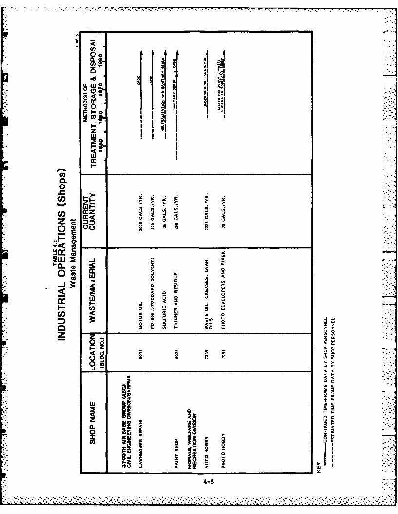
00
i ' 21 1 .i .,0 iju0 0 0 2
I l I
ac a;IzOI 1-iW ca!
I-n IZjJ t
w I
0 - L
U-3 wc S ~ -
zO aC :) z0 10 IL w w
CW W0: CL
00 0nI
WJ LuCL C
Z Cl' 0.u
.c 6 01. 0
0j >. .n '- ..a.
za. Znn -00
<0 00C.)0 VA 5n, 5.
Om000
<'
4-5I
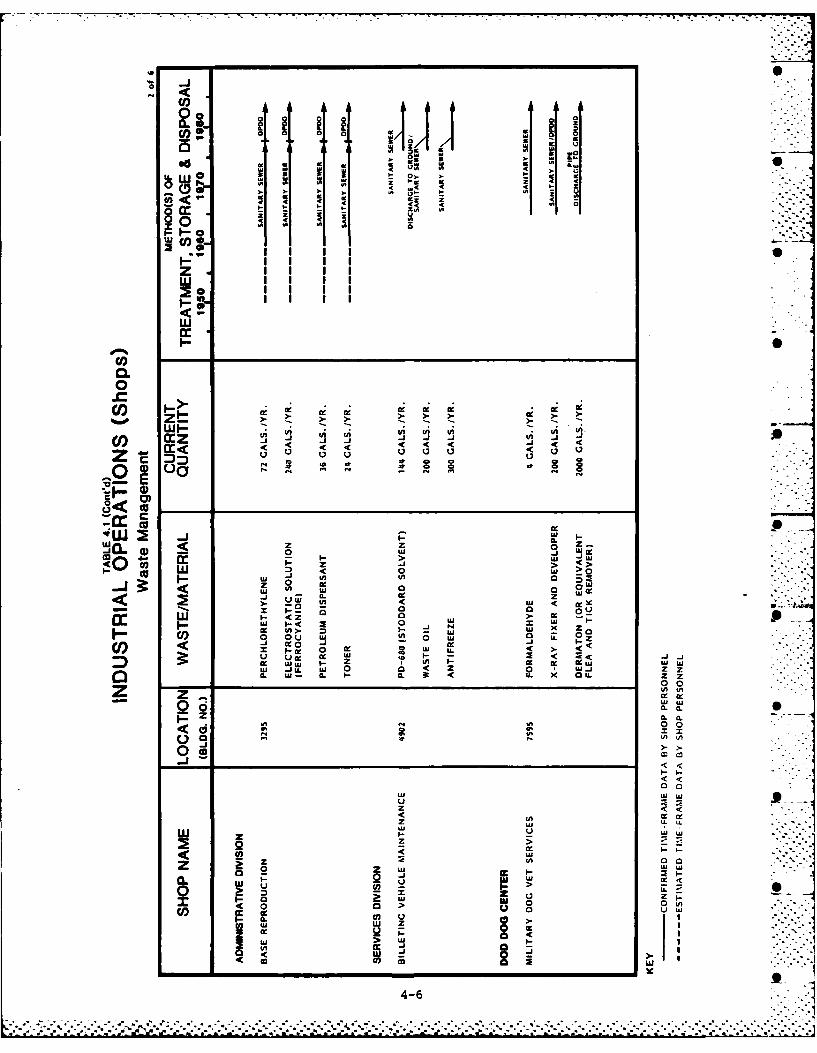
8 S0
. w £ w£
). t . 0z z z
4 4£z 2
F: .4 4V- -zV
z wV
% Ii I%*
I - $A
C',
CoL zz InUz n
.c -'. a: w
3t I < z 0 cc _ __ _ __ _ __ _ __ _ __ _ _
J Cz 0 Z..
0c W j
c I- w Ac 9 C L uuzi JJ ).0<0 0.
0. CL
0U 0
< <
u, oz VUz -C < C~z~ i-u0
0 Z
z ZU wQo 0.0.
0.0
<0i >i0-,L If I
S2. n f
-I-~~~~~~~I __ _ _ _ _ _ _ __ _ _ _ _ _ _
u'
us
4-
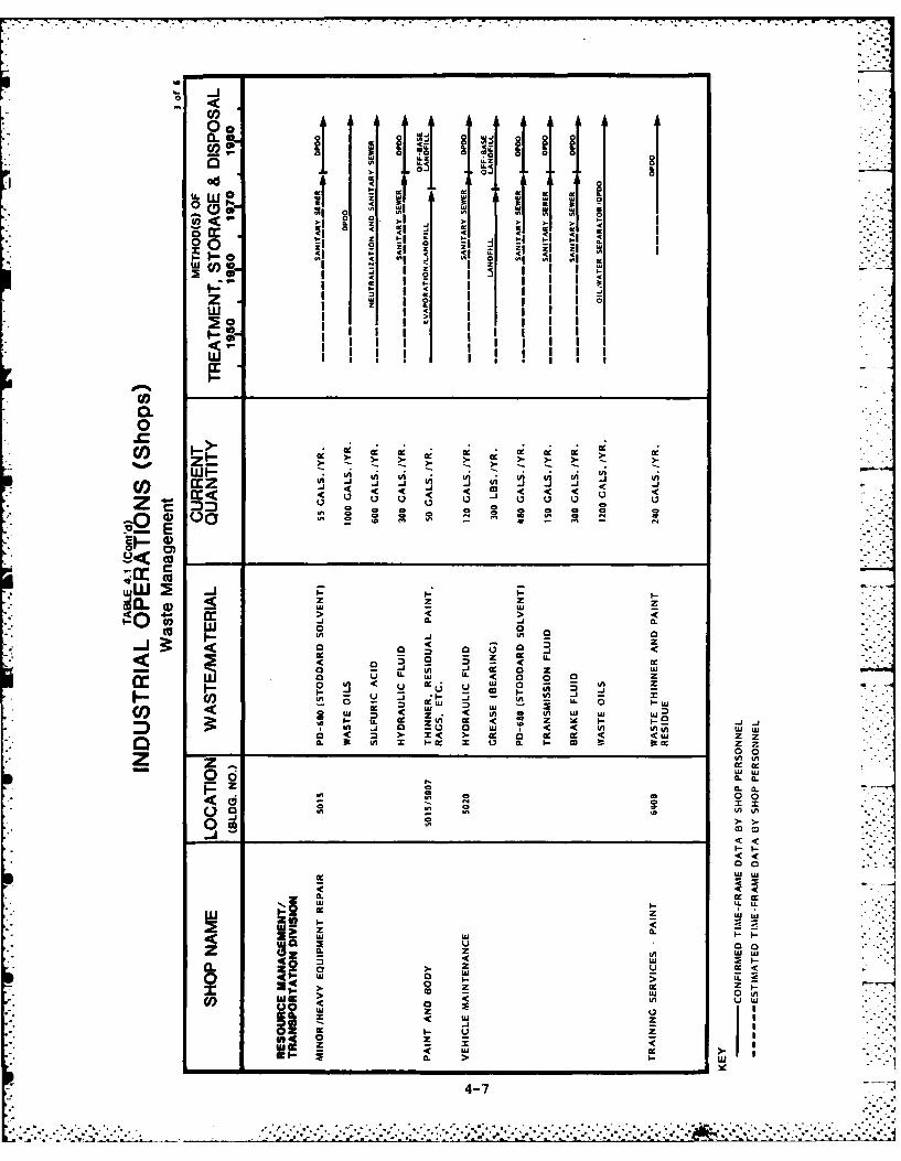
aa
-> >
0 I I 2 i
w I z
(0 -
>. 4. Q .
-) 0
40 4. > >
.u0 0 0 - -I
<J0.- 0.
cc 0 < u 0 .
!2 ; - w U. 0 0
10 W-Zw 090.0.
D i a )<< LnV .LOm m L '
0 0
W w
Cz 0.* 0 U
0 z.
WC W-j re--
I U CZ
a. z a: < . . . . . aLU *jU. * - ~ 2 J 2. .
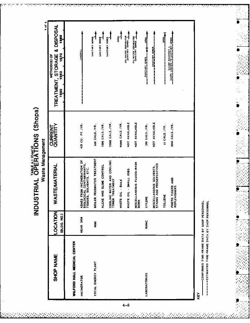
0 0-I
Cip, AA AA
U- w > U
sl i- I oI
P- I 0 t: I IzI I I If
Ij (1) I
I I 2
I I Icar
Oo
0I- w
cca c j j.4-
COc .a
zl :D: cc'~ j-S2 0. 0 )-
z - z
Wu< ca
0 0 x %
0.o oi >
I 0 zU oo
... u z ..-I - lu < I.(x - 4
0 ui 0 LU. 3:
CRE wj w a -l Ww< tJ tuL J J zz
Vn- 0 J 0 Ci~ -i- 0 W zzzC0 CIn w i 3 w 30 xj 3w I 0.
Lq.0 01 0-0 < 0 >
U0 0
aU U 00* CL (
0. w
W w
z u
o IA
re ww
z 00
wU
0
4-8%
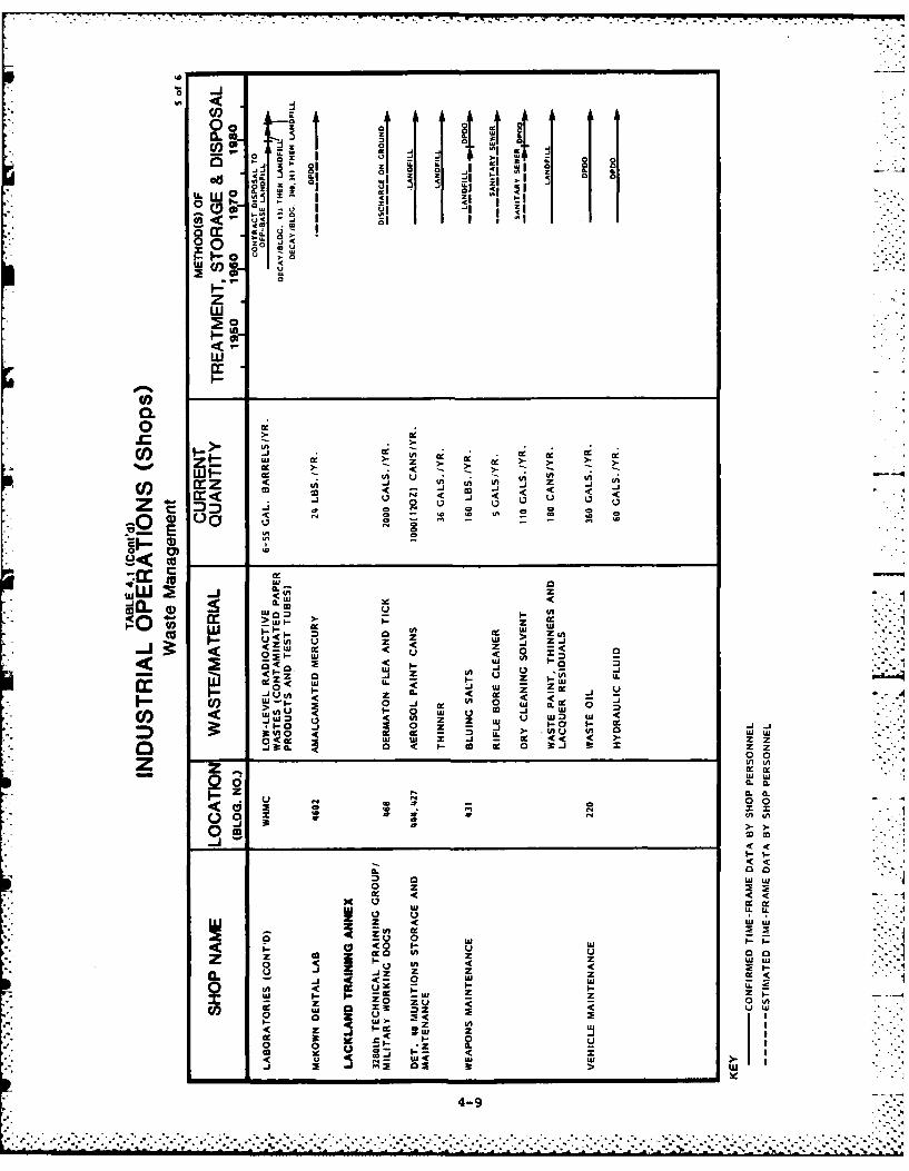
-1 2
a.
0 0lug a ~ 0 . 4 .9 A
0 I' 0u 0
-Z Z
u -
0z
w
wI-
C,0.
PJ .z Wf tU - - z --i-to- -J< <
0z rm w
-JC C 0 0
LU to,- 0 4.- 0j
u 0 z U>j Z
<0 40 cc<0
IaZ a 0 A n
P- I
> ' UIa ujZ i
__ a .( UI 0 3 -1:_
W~~ 00 -
CL ICL 9
~~~ 0uui
< <
CL 0 . . -
0 0 zwoc <
w cc c-wj E < 44
4c -< Aw0 in- 0<
I- I- M tU0U Z 0. 0 (
z v < uuLS m *z
a
4-9
4-9
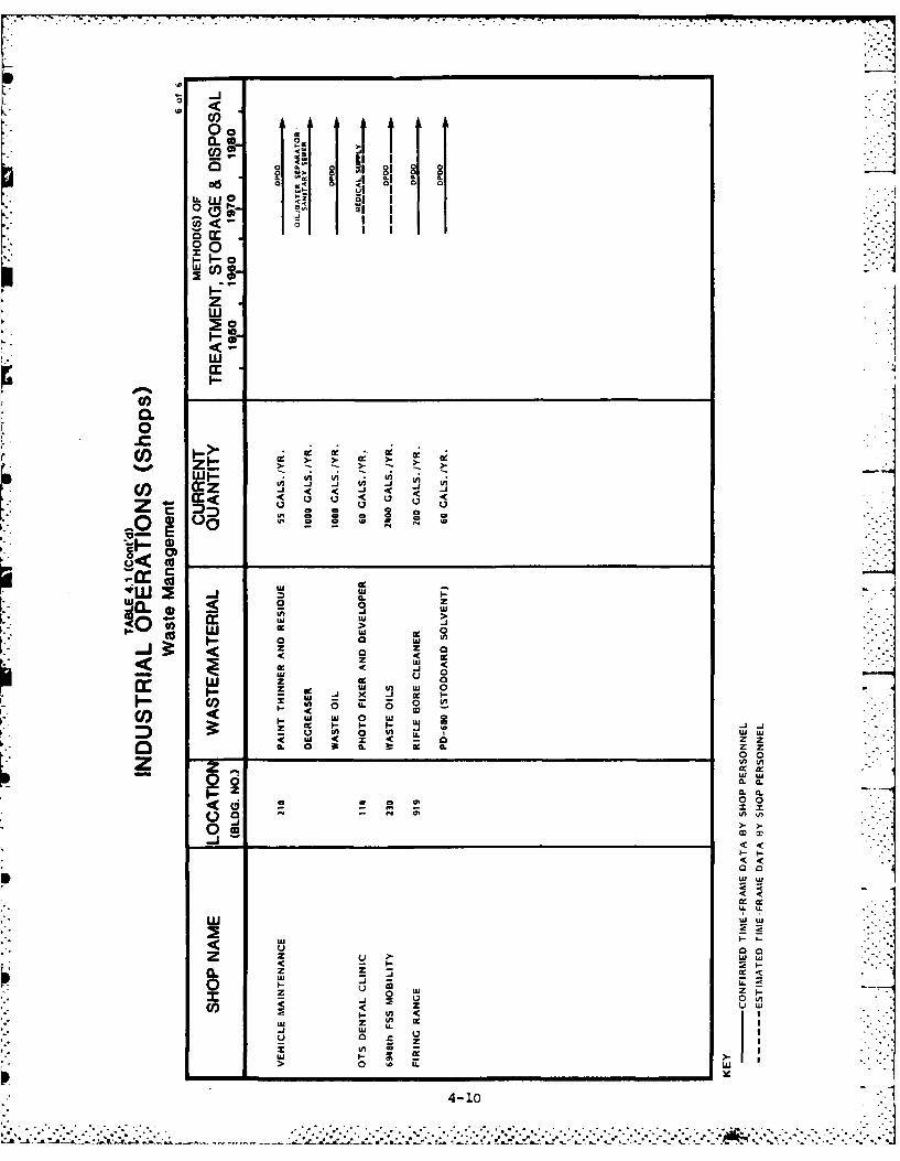
ID <
00
CL
L. lI
0~ 0
w
wcc
C-
CO.
z U U
LU 0
W w 0
w~~ I :- z_ ~J
Ofi w 0n LI- LC, - i w
0o~. 0 LL 0ui If 0 I U Icc 'C w 1 -j
0.0
0.(
W LuW
0 0
0 -)
W Ul
I-ii
z z W
LU J
4-10
u .
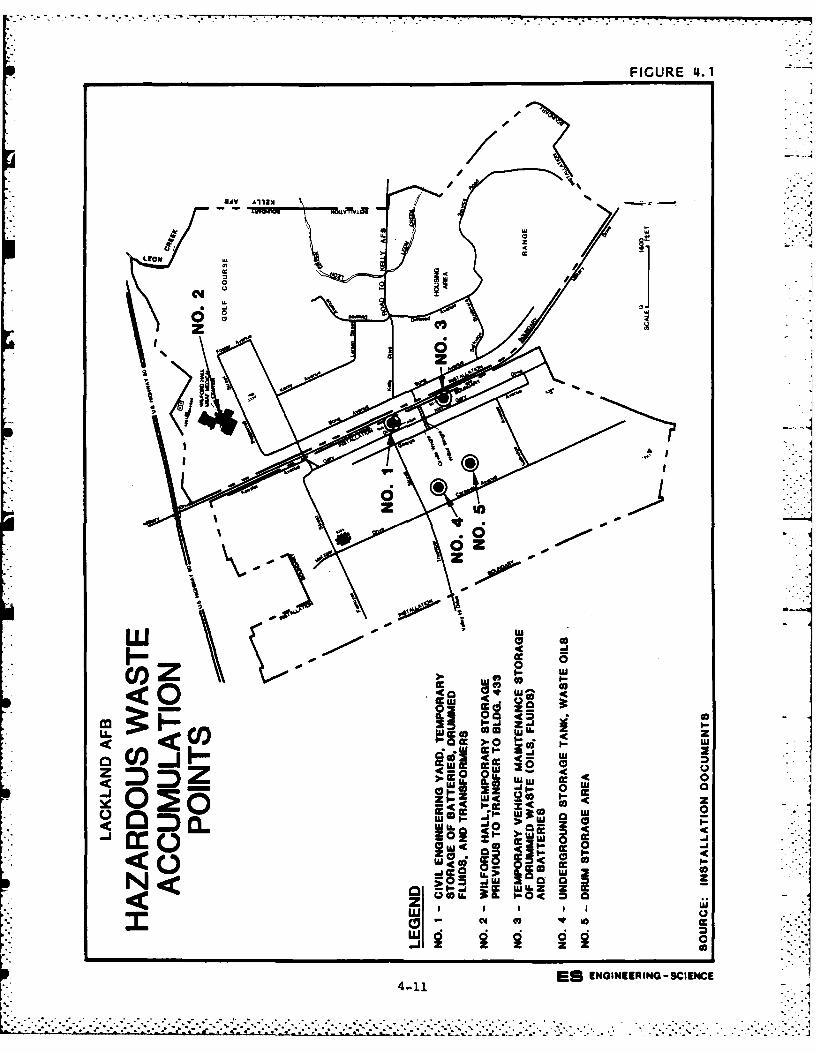
FIGURE 4. 1
a'f
8A A13
Ltof2
z) ' a z
z;
d z
00
40 ,a 0
C z a 9WuL z
wl '-Q ). 0
us 0
u 1...1
m a -A .. 0..\
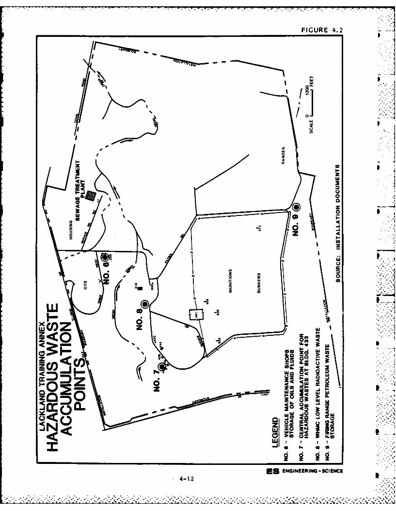
FIGURE 4.2
I
ILI I-
x I-.. . .
oz
-Z-
z j
1<0 -C
ILO-
ow
:z UJ 0
zw ao 0 4
Lu~~ wl-w4 5Lu00
ESENINERN - SIENCE
4-12
hazardous wastes including known PCB transformers, solvents and thinners
(toluene, xylene, petroleum naptha, perchlorethylene) before DPDO pick-
up. Battery cases are stored at sites No. 1 and No. 3 before DPDO
pickup. Waste oils are generally stored and picked up at these and
other accumulation points on base.
Currently low-level radiological wastes generated by hospital acti-
vities are stored at Buildings 341 and 340, an old AEC radioactive
secure facility (Site No. 8). The low-level radioactive wastes have
short half-lives (less than 65 days). They are allowed to decay in this
facility for ten half-lives or until only background levels of radiation
are detected. At that point, these wastes are disposed of in ordinary
landfills. Prior to 1981, these wastes were managed by an off-site
contractor and taken to a landfill approved for low-level radioactive
waste disposal.
No large spills or other similar problems were reported with cur-
rent waste storage and accumulation areas. Sites No. 6 and No. 9 at the
Lackland Training Annex are petroleum and rifle bore cleaner waste
storage sites that do not have sufficient containment to prevent run off
or to contain minor spills and residue from reaching nearby soils.
Minor contamination of soils next to these sites was evident from the
oily discoloration noted on these soils.
Fuels Management
Unlike many Air Force installations, Lackland AFB and Lackland TA
do not have airplanes to fuel, service and maintain. Therefore, an
extensive fuels management, distribution and delivery program is not in
place. Most fuel related activities support fuel supply activities for
the auxiliary diesel generators and gasoline supply tanks located at
over 40 locations throughout Lackland AFB and over 30 sites at the
Lackland TA. Three tanks previously used for radioactive waste-waters
were left in place at Lackland TA from previous AEC operations. A
listing of tanks located at Lackland AFB and Lackland TA, their contents
and status is presented in Table 4.2 and 4.3, respectively.
Spills and Leaks
Since 1981, only one spill of major consequence has occurred. In
April of 1983, a spill of PCB transformer oil occured near Building
5100, by the corner of Kirkland Street and Gary Avenue. Approximately I
4-13
• ..'.... ..., .... ... ., .- .' .• ..-, .. ,.- ., ..• .°. ,.... ....."..........- .. . "' . ;.. . '.. "... ... ".... .,.' .. . "
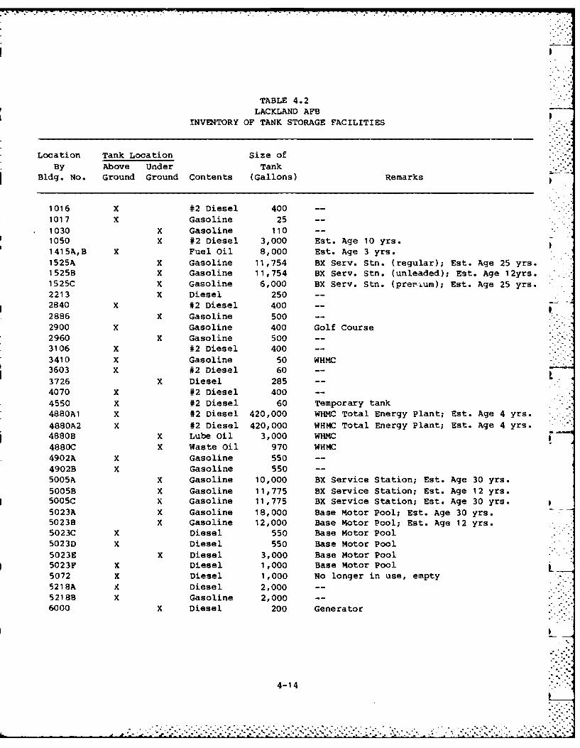
TABLE 4.2LACKLAND AFB
INVENTORY OF TANK STORAGE FACILITIES
Location Tank Location Size ofBy Above Under Tank
Bldg. No. Ground Ground Contents (Gallons) Remarks
1016 X #2 Diesel 400
1017 X Gasoline 25
1030 X Gasoline 1101050 X #2 Diesel 3,000 Est. Age 10 yrs.1415A,B X Fuel Oil 8,000 Est. Age 3 yrs.1525A X Gasoline 11,754 BX Serv. Stn. (regular); Est. Age 25 yrs.1525B X Gasoline 11,754 BX Serv. Stn. (unleaded); Est. Age 12yrs.1525C x Gasoline 6,000 BX Serv. Stn. (prer'um); Est. Age 25 yrs.
2213 X Diesel 250 --
2840 X #2 Diesel 400
2886 X Gasoline 500 --
2900 X Gasoline 400 Golf Course2960 X Gasoline 500 --
3106 X #2 Diesel 400 --
3410 X Gasoline 50 WHMC3603 X #2 Diesel 60 --
3726 X Diesel 285 --
4070 X #2 Diesel 400 --
4550 X #2 Diesel 60 Temporary tank4880Al X #2 Diesel 420,000 WHMC Total Energy Plant; Est. Age 4 yrs.
4880A2 X #2 Diesel 420,000 WHMC Total Energy Plant; Est. Age 4 yrs.4880B X Lube Oil 3,000 WHMC4880C X Waste Oil 970 WHMC
4902A X Gasoline 5504902B X Gasoline 550 --
5005A X Gasoline 10,000 BX Service Station; Est. Age 30 yrs.5005B X Gasoline 11,775 BX Service Station; Est. Age 12 yrs.5005C X Gasoline 11,775 BX Service Station; Est. Age 30 yrs.5023A X Gasoline 18,000 Base Motor Pool; Est. Age 30 yrs.50238 x Gasoline 12,000 Base Motor Pool; Est. Age 12 yrs.5023C X Diesel 550 Base Motor Pool5023D X Diesel 550 Base Motor Pool5023E X Diesel 3,000 Base Motor Pool5023F X Diesel 1,000 Base Motor Pool5072 X Diesel 1,000 No longer in use, empty5218A A Diesel 2,000 --
52188 X Gasoline 2,000 --
6000 X Diesel 200 Generator
- .7 -
4-14
..................................
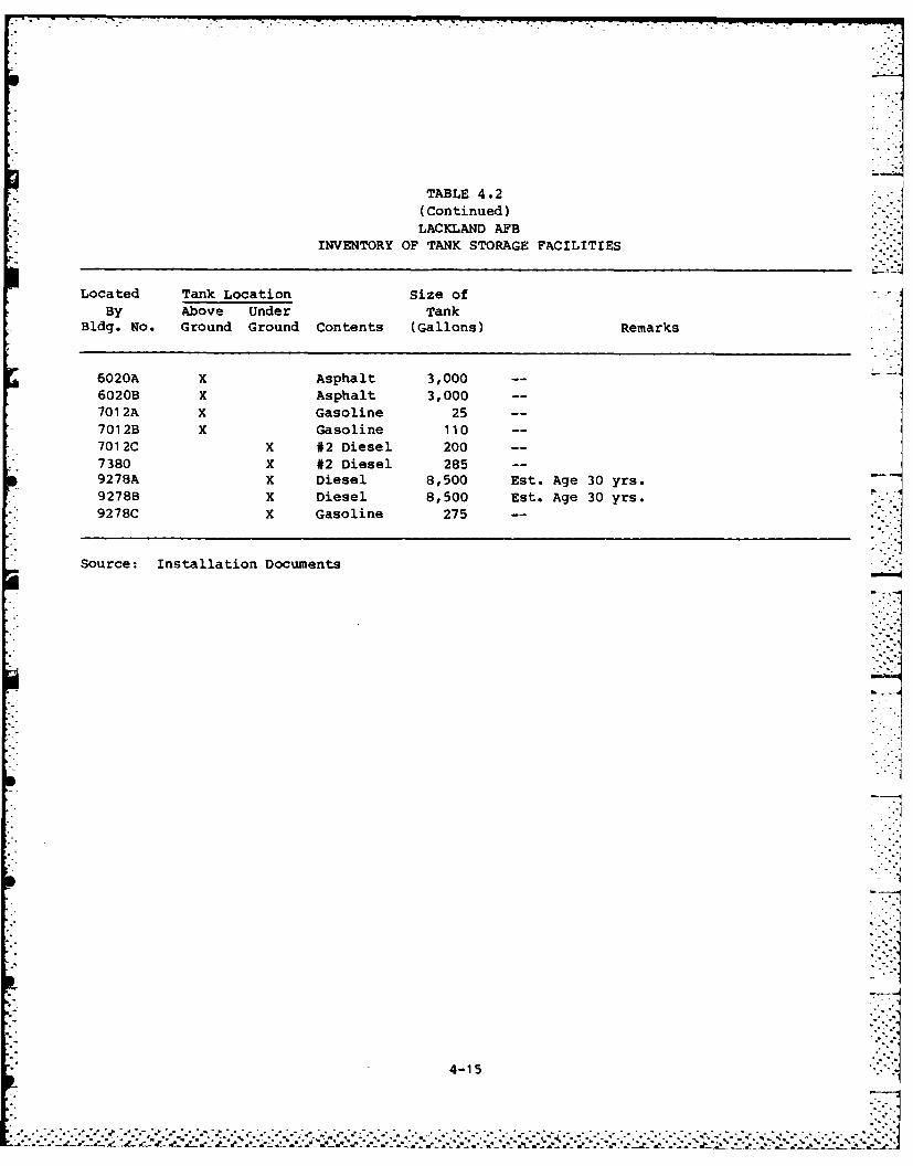
TABLE 4.2
(Continued)LACKLAND AFB
INVENTORY OF TANK STORAGE FACILITIES
Located Tank Location Size ofBy Above Under Tank
Bldg. No. Ground Ground Contents (Gallons) Remarks
r 602A x Aphalt 3,0i6020B X Asphalt 3,000 -
7012A x Gasoline 25 -
7012B X Gasoline 110 -
7012C X #2 Diesel 200 -
7380 x #2 Diesel 285 -
9278A X Diesel 8,500 Est. Age 30 yrs.9278B K Diesel 8,500 Est. Age 30 yrs.
*9278C X Gasoline 275 -
* Source: Installation Documents
4-15
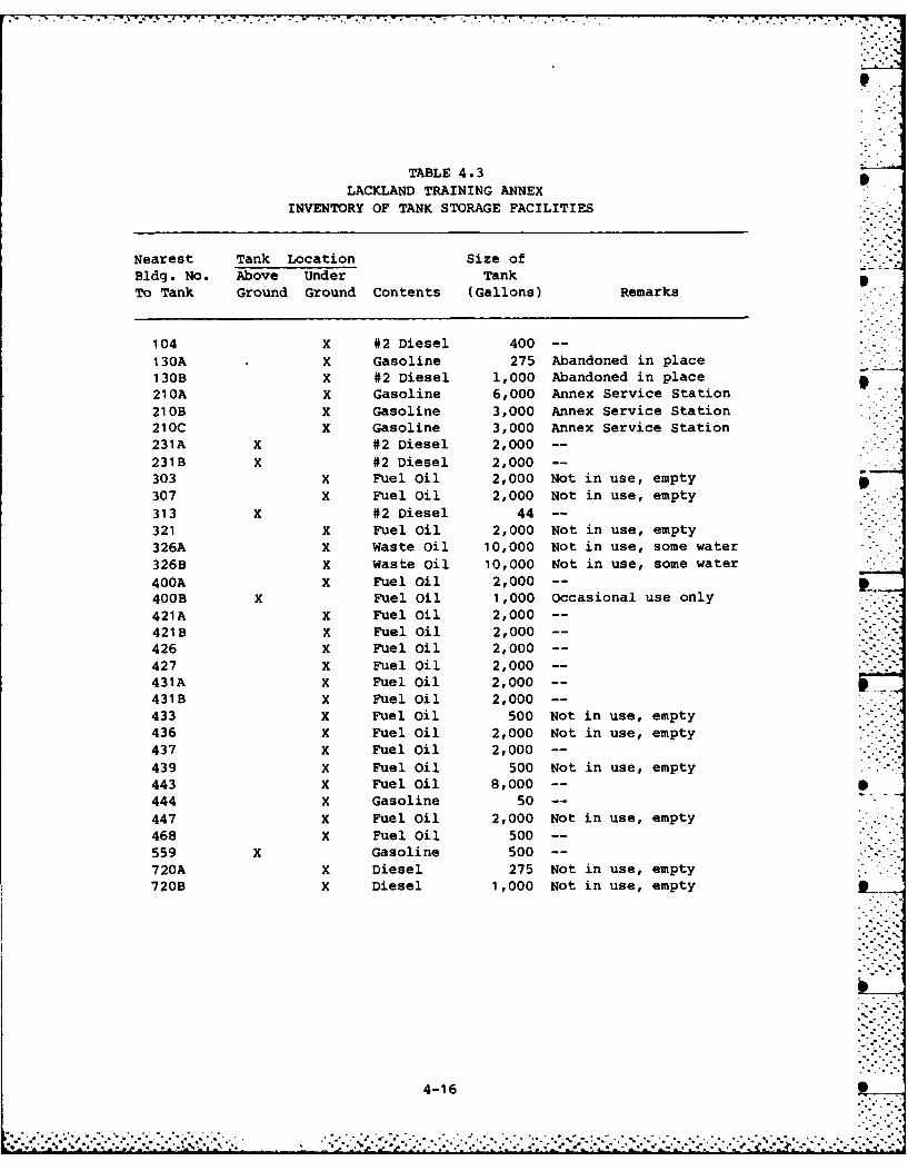
- -. . -. ~ ... .... - .- -. -- - - . - - . .--. .
TABLE 4.3LACKLAND TRAINING ANNEX
INVENTORY OF TANK STORAGE FACILITIES
Nearest Tank Location Size ofBldg. No. Above Under TankTo Tank Ground Ground Contents (Gallons) Remarks
104 X #2 Diesel 400 -
130A X Gasoline 275 Abandoned in place .130B X #2 Diesel 1,000 Abandoned in place210A X Gasoline 6,000 Annex Service Station210B X Gasoline 3,000 Annex Service Station210C X Gasoline 3,000 Annex Service Station231A X #2 Diesel 2,000 --
231B X #2 Diesel 2,000 --
303 X Fuel Oil 2,000 Not in use, empty p307 X Fuel Oil 2,000 Not in use, empty313 X #2 Diesel 44 --
321 X Fuel Oil 2,000 Not in use, empty326A X Waste Oil 10,000 Not in use, some water326B X Waste Oil 10,000 Not in use, some water400A X Fuel Oil 2,000 --
400B X Fuel Oil 1,000 Occasional use only421A X Fuel Oil 2,000 --
421B X Fuel Oil 2,000 -- --
426 X Fuel Oil 2,000 --
427 X Fuel Oil 2,000 --
431A X Fuel Oil 2,000 --
431B X Fuel Oil 2,000 --
433 X Fuel Oil 500 Not in use, empty436 X Fuel Oil 2,000 Not in use, empty437 X Fuel Oil 2,000 --
439 X Fuel Oil 500 Not in use, empty443 X Fuel Oil 8,000 --
444 X Gasoline 50 --
447 X Fuel Oil 2,000 Not in use, empty468 X Fuel oil 500 -
559 X Gasoline 500 --
720A X Diesel 275 Not in use, empty720B X Diesel 1,000 Not in use, empty _
4-16
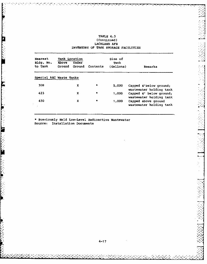
- , . *. .]
TABLE 4.3(Continued)
LACKLAND AFBINVENTORY OF TANK STORAGE FACILITIES
Nearest Tank Location Size ofBldg. No. Above Under Tankto Tank Ground Ground Contents (Gallons) Remarks
Special AEC Waste Tanks
308 X * 5,000 Capped 4'below ground;wastewater holding tank
423 X * 1,000 Capped 4' below ground;wastewater holding tank
430 X * 1,000 Capped above groundwastewater holding tank
* Previously Held Low-Level Radioactive WastewaterSource: Installation Documents
.17
4-1-7
. ... o
gallon of this oil spilled onto the soil penetrating less than 1 foot
into the soil profile. Rapid response by base personnel prevented
further migration. Contaminated soils were collected, placed in drums
and manifested to a hazardous waste landfill. The remaining soil was
tested to assure decontamination was complete. Previous to 1981, no
other major spills or leaks were reported by personnel or in records
reviewed.
Evidence of two uncontrolled releases were observed. These sites
occurred at the discharge to the oil-water separators located at WHMC --
and Building 5020 (discussed later). It is not possible to estimate the
quantities of spillover oil that has been released at these sites. The
soil was found to be oil stained at both spill sites which are located
in open drainage ditches.
In about 1972, a fuel tank truck explosion occurred at facility
1525 during a fuel delivery. About 4000 gallons of gasoline was lost
and all of it combusted at the site.
Pesticide Utilization
Several pesticides have been used for controlling weeds, insects,
rodents and fungus at Lackland AFB and Lackland TA. These are used by
entomology and the golf course.
Pesticides used at the golf course have been mixed outside and west
of the Golf Course Maintenance Building 2960. Empty pesticide contain-
ers and bags have routinely been put in dumpsters and taken to landfill
disposal. Cans received multiple rinses and were punched with holes
starting in the early 1970's. Rinsewater from the can washing was
discharged to the ground in the mixing area. No major vegetation stress
was observed at this site. All residual solutions in spray equipment
has been randomly sprayed on the golf course. Sprayers are rinsed at
various locations and sprayed on the golf course grounds.
The pesticides used at areas other than the golf course have been
mixed at the Entomology Building 5394 since the 1950's. Prior to that -1
time the chemicals were mixed in the 6000 area. Mixing of pesticides
for the large exterior spray equipment is done outside at the north end -. ,-:
of Building 5394 and mixing for the small sprayers is done inside the '
building.
4-18
,. --.*.. . . .
.. 7
Entomology pestic ie containers have been triple rinsed since about
1974. The rinsewater from the containers is put back into the sprayers
for dilution water. Both the large and small sprayers are rinsed after
use. Rinsewater from the large sprayers is currently sprayed at various
locations on the base. In the 1960's the rinsewater was discharged in - -
the drainage ditch just west of Building 5394. The rinsewater from the
small sprayers is discharged on the ground at the north end of Building
5394. When the pesticide operations were in the 6000 area rinsewater
went to the sanitary sewer. one former employee indicated that in the
1960's vegetation damage occurred at the north side of Building 5394 and
in the two adjoining drainage ditches from drainage of pesticide resid-
uals.
It was reported by one employee that in about 1968 a large quantity
of chlordane was delivered to Entomology. The bags of pesticide were
stored for some time while attempts were made to turn the material back
into supply. However, the stored bags began deteriorating and the
excess (estimated at about one ton) was placed in plastic bags and taken
to the Medina facility landfill.
Fire Protection Training
Fire training activities have been conducted at two locations at
Lackland AFB (Figure 4.3). The earliest one known to have operated was
located about where Building 2850 now exists. Fire Protection Training
Area (FPTA) No.1 was utilized sporadically in the 1950's and 1960's.
The site consisted of an old building and a fire pit. Wooden pallets
and other solid materials were used to fuel training fires conducted in
the building. Waste oils and other liquid industrial wastes (such as
solvents) were used for fueling fires in the pit. The frequency of
training activities typically consisted of about two fires at the pit
per year. For each fire approximately three to four drums of waste
liquid were poured on the ground; no water was applied to the ground
before the waste liquid.
In the early 1970's (approximately 1971) Fire Protection Training
Area No. 2 started to be used and it continues in operation at this
time. The site used a fire pit constructed on the ground until 1977
when the existing concrete burning area was constructed. Waste liquids
such as oils and solvents were used for the fires at FPTA No. 2 until
4-19
''$','.;:', ; " - ,' -'.".' " '-•• I',.-'.-.-." '2 ,'.".-". . "."."-"-""""""""" .... ' .' .: '-'
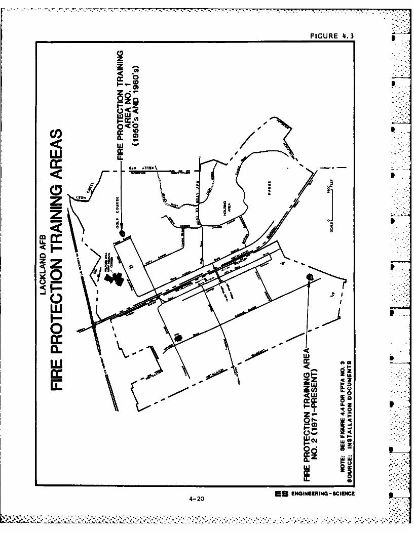
FIGURE 4.3
02C
P) z
LLJ -
z0<o z
0
w. <
ww0
't
w
0
asEGNING CIOL4I-20
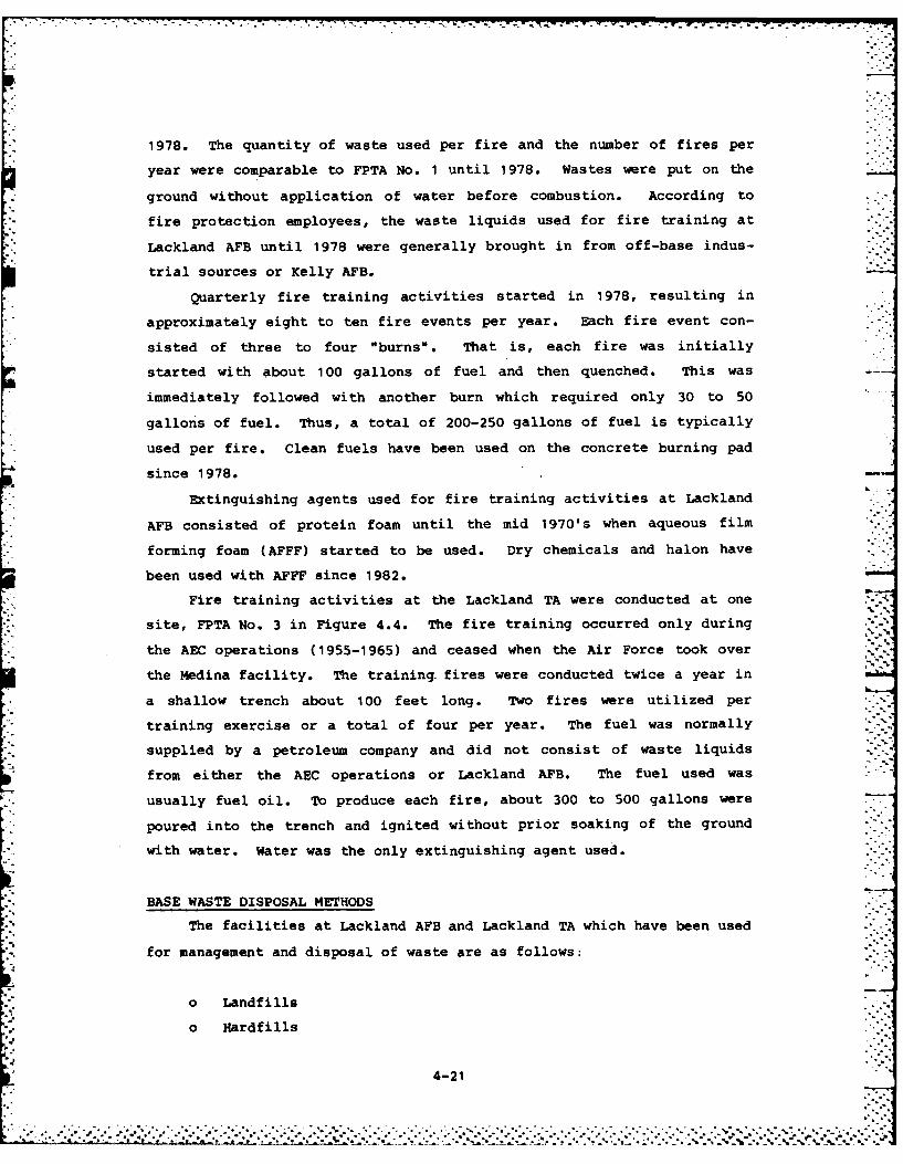
1978. The quantity of waste used per fire and the number of fires per
year were comparable to FPTA No. 1 until 1978. Wastes were put on the
ground without application of water before combustion. According to
fire protection employees, the waste liquids used for fire training at
Lackland AFB until 1978 were generally brought in from off-base indus-
trial sources or Kelly AFB.
Quarterly fire training activities started in 1978, resulting in
approximately eight to ten fire events per year. Each fire event con-
sisted of three to four "burns". That is, each fire was initially
started with about 100 gallons of fuel and then quenched. This was
immediately followed with another burn which required only 30 to 50
gallons of fuel. Thus, a total of 200-250 gallons of fuel is typically
used per fire. Clean fuels have been used on the concrete burning pad
since 1978.
Extinguishing agents used for fire training activities at Lackland
AFB consisted of protein foam until the mid 1970's when aqueous film
forming foam (AFFF) started to be used. Dry chemicals and halon have
been used with AFFF since 1982.
Fire training activities at the Lackland TA were conducted at one *':
site, FPTA No. 3 in Figure 4.4. The fire training occurred only during
the AEC operations (1955-1965) and ceased when the Air Force took over
the Medina facility. The training, fires were conducted twice a year in
a shallow trench about 100 feet long. Two fires were utilized per
training exercise or a total of four per year. The fuel was normally
supplied by a petroleum company and did not consist of waste liquids
from either the AEC operations or Lackland AFB. The fuel used was
usually fuel oil. To produce each fire, about 300 to 500 gallons were
poured into the trench and ignited without prior soaking of the ground
with water. Water was the only extinguishing agent used.
BASE WASTE DISPOSAL METHODS
The facilities at Lackland AFB and Lackland TA which have been used
for management and disposal of waste are as follows:
o Landfills
o Hardfills
4-21
2 ... .°• -° - - ": % ".1 -. " '- , ' a
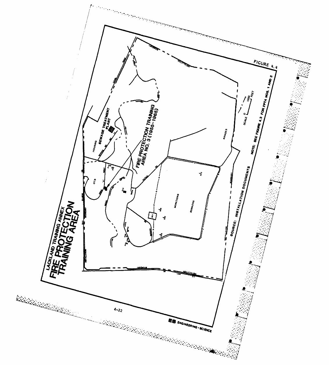
ICR
IcI
C II
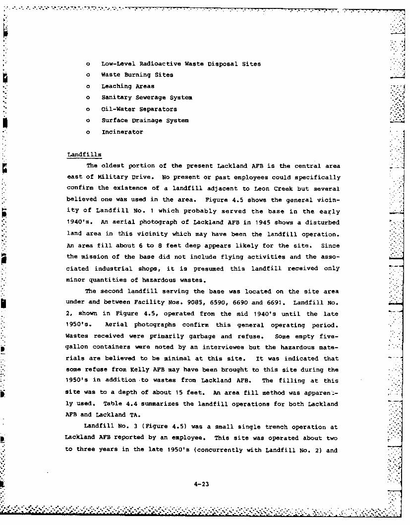
o Low-Level Radioactive Waste Disposal Sites
o Waste Burning Sites
o Leaching Areas
o Sanitary Sewerage System
o Oil-Water Separators
o Surface Drainage System Io incinerator
Landfills
The oldest portion of the present Lackland AFB is the central area
east of Military Drive. No present or past employees could specifically
confirm the existence of a landfill adjacent to Leon Creek but several
believed one was used in the area. Figure 4.5 shows the general vicin-
ity of Landfill No. 1 which probably served the base in the early
1940's. An aerial photograph of Lackland AFB in 1945 shows a disturbed
land area in this vicinity which may have been the landfill operation.
An area fill about 6 to 8 feet deep appears likely for the site. Since
the mission of the base did not include flying activities and the asso-
ciated industrial shops, it is presumed this landfill received only
minor quantities of hazardous wastes.
The second landfill serving the base was located on the site area
under and between Facility Nos. 9085, 6590, 6690 and 6691. Landfill No.
2, shown in Figure 4.5, operated from the mid 1940's until the late
1950's. Aerial photographs confirm this general operating period.
Wastes received were primarily garbage and refuse. Some empty five-
gallon containers were noted by an interviewee but the hazardous mate-
rials are believed to be minimal at this site. It was indicated that
some refuse from Kelly AFB may have been brought to this site during the
1950's in addition -to wastes from Lackland AFB. The filling at this
site was to a depth of about 15 feet. An area fill method was apparent-
ly used. Table 4.4 summarizes the landfill operations for both Lackland
AFB and Lackland TA.
Landfill No. 3 (Figure 4.5) was a small single trench operation at
Lackland AFB reported by an employee. This site was operated about two '
to three years in the late 1950's (concurrently with Landfill No. 2) and
4-23
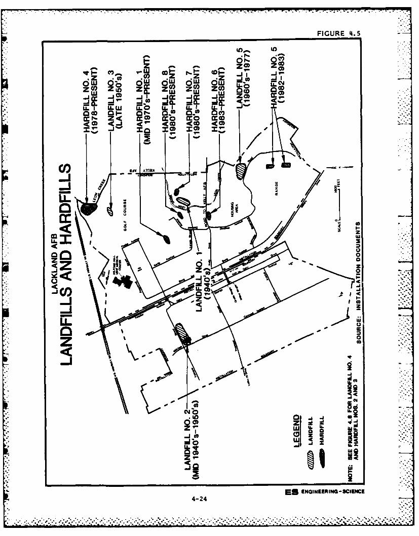
FIGURE 4.5
v~I Col.~ Y.W 0- r,1 o -J _j
~ 0) ~ o~
CO COv Z1U LO- a Z() C o
a:9 L 0 wL U
00
00coI
Z Zcd 4
LL (9
co)
zJ ,zII ii
4-C4
*. . . .. . . . . . . . ... * .*%**. . . . . . . * .%* .- ,....
00........ ...
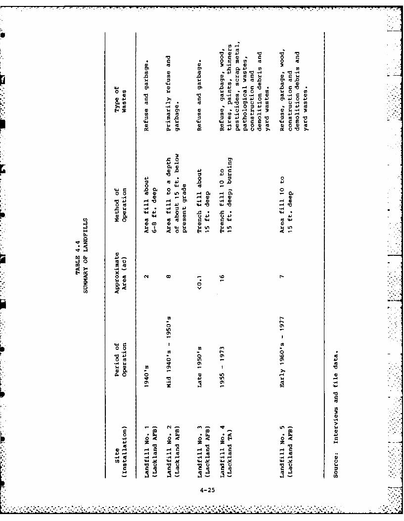
0 C 4) 04j~ 0 .,
02m vCj4 0 0)0 4 *J~ 0'2' $'2'4
4.4 to00 0 U 0)00 wC %2 (aJ -02'2 .0'
002: ty ed 4 4 ) *4 40 4-fl 41 0 02
0 0 '0s 0. 2 .. 4j to 4~.4j$4ON d 0 -4 $O-A 0~J4
U) f -02j4202 m 4140:3 0 .0 Q) C m 0 V 0 m 0
-0 42 0 0 $4 -41 0) .:V$ 4 c 4$4c 4 ) , (L) 16 020Q)dJ d 02) 0-4
0 0.( 0 .'0U0r 0 0
.00 0 c
0 410 .0 44 0)02
0 0 Id 4) 4 .- 4 04 0.14 4) . - .4 ) ) r- )A.) -4 44 ON - 4 )4 4
0) ~ ~ 004 4
>44E-44
40 rd O-to
04 $4
oEn'
44'
0 0 9
$4.
(U '24) LA 4.,.4 A(
-4
0 owL rk Ai*z,4-1 0 oc ot O. c ~ r.
.41. z z -442 .-40 9425
. . .. . .*. * . ... .. . .. .... . .
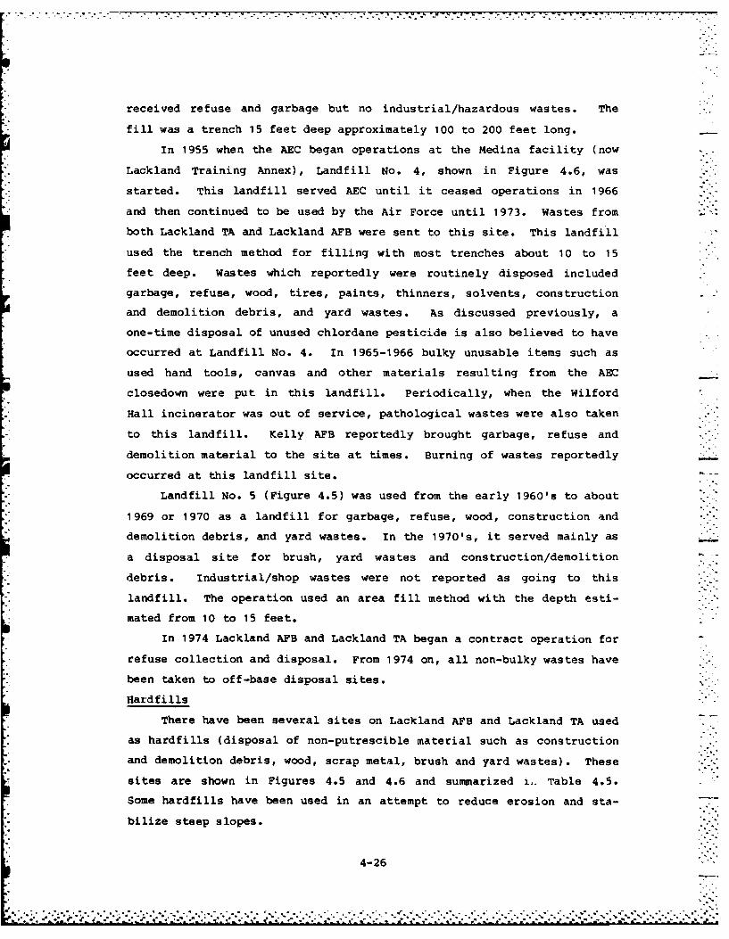
received refuse and garbage but no industrial/hazardous wastes. The
fill was a trench 15 feet deep approximately 100 to 200 feet long.
In 1955 when the AEC began operations at the Medina facility (now
Lackland Training Annex), Landfill No. 4, shown in Figure 4.6, was
started. This landfill served AEC until it ceased operations in 1966
and then continued to be used by the Air Force until 1973. Wastes from
both Lackland TA and Lackland AFB were sent to this site. This landfill
used the trench method for filling with most trenches about 10 to 15
feet deep. Wastes which reportedly were routinely disposed included
garbage, refuse, wood, tires, paints, thinners, solvents, construction
and demolition debris, and yard wastes. As discussed previously, a
one-time disposal of unused chlordane pesticide is also believed to have
occurred at Landfill No. 4. In 1965-1966 bulky unusable items such as
used hand tools, canvas and other materials resulting from the AEC
closedown were put in this landfill. Periodically, when the Wilford
Hall incinerator was out of service, pathological wastes were also taken
to this landfill. Kelly AFB reportedly brought garbage, refuse and
demolition material to the site at times. Burning of wastes reportedly -
occurred at this landfill site.
Landfill No. 5 (Figure 4.5) was used from the early 1960's to about
1969 or 1970 as a landfill for garbage, refuse, wood, construction and
demolition debris, and yard wastes. In the 1970's, it served mainly as
a disposal site for brush, yard wastes and construction/demolition
debris. Industrial/shop wastes were not reported as going to this
landfill. The operation used an area fill method with the depth esti-
mated from 10 to 15 feet.
In 1974 Lackland AFB and Lackland TA began a contract operation for
refuse collection and disposal. From 1974 on, all non-bulky wastes have
been taken to off-base disposal sites.
Hardfills
There have been several sites on Lackland AFB and Lackland TA used
as hardfills (disposal of non-putrescible material such as construction
and demolition debris, wood, scrap metal, brush and yard wastes). These
sites are shown in Figures 4.5 and 4.6 and summarized i,. Table 4.5.
Some hardfills have been used in an attempt to reduce erosion and sta-
bilize steep slopes.
4-26
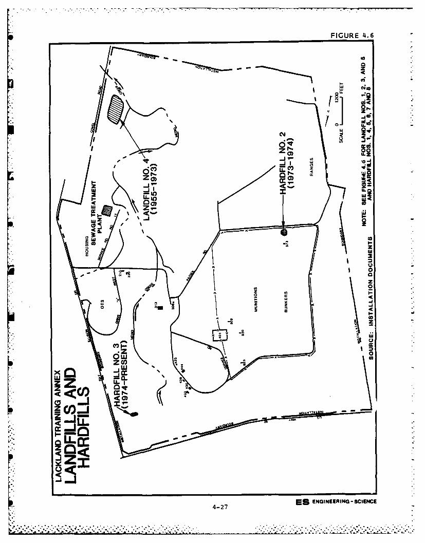
FIGURE 4.6
C% U
ILZ
Iw
wz
z 0
Uz_j0
LI-
zo crz
z i x
ulZZ
.19 .I a ** * * *
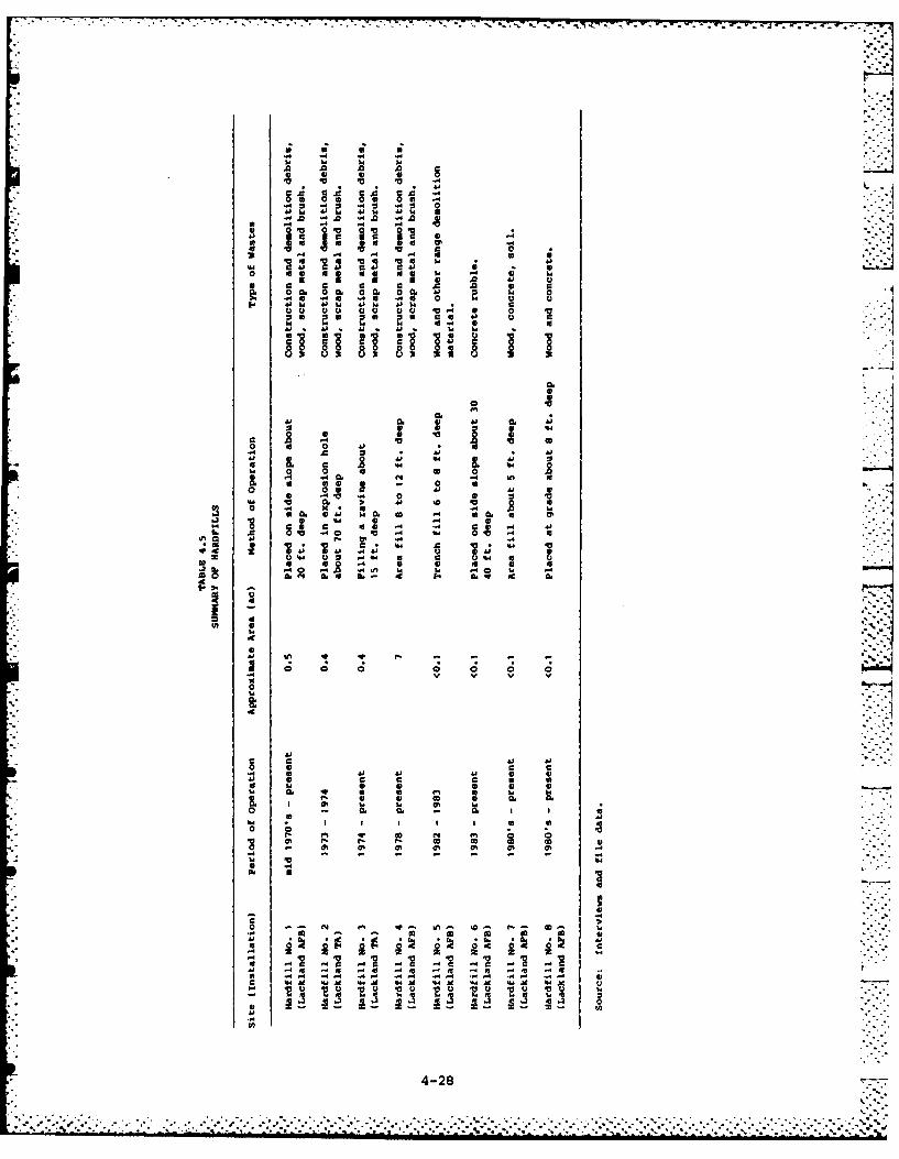
A2 A A ' A0 .4 4 U4 .
4j 4j
Ca CCLACA .-4~~~~ kw0.~ ~ :2
- V4 %D
3 u 14- 4 0.U
a a a A aj
00 A0. 00I0VI.
E Ej 44 c44 0 cI C
t6 GO CE 44 8
0,0.
0 u E0
0. S44 0. U 44 0. 4
0 U 0 U 28
a WU 0
-e :v•
Hardfill No. 1 (Figure 4.5) was started in the 1970's and has been
used periodically to the present time. The fill depth is estimated at
20 feet.
Hardfill No. 2, located at the Lackland TA as shown in Figure 4.6,
was operated for only a year or two (1973 - 1974). This site was the
location of a munitions bunker explosion which occurred when AEC was
operating the site in the early 1960's. Concrete rubble, brush and yard
wastes were placed in the explosion hole (about 70 feet deep).
Another hardfill (Hardfill No. 3) located at the Lackland TA
(Figure 4.6) was started in approximately 1974 and appears to still be
receiving wastes. The site is in a ravine and the wastes are uncovered.
Materials discarded at the site include concrete, wood, brush, major
appliances, and other bulky items. The fill depth is approximately 15
feet.
Hardfill No. 4 located at Lackland AFB (Figure 4.5) began opera-
tions in 1978 and continues at the present time. Depth of fill on the
site is variable and is estimated at 8 to 12 feet. During the on-site
visit for this study there was considerable solid waste observed dumped -
on top of the ground between the Lackland AFB boundary and U.S. Highway
90 near Hardfill No. 4. This unauthorized disposal site is off base
property.
Hardfill No. 5 operated 1982 to 1983 (Figure 4 5). It consisted of -
two trenches, 6 to 8 feet deep, which received wood and other demolition
material from the firing range.
From 1983 to the present time, concrete rubble has been dumped and
not covered adjacent to Kelly Drive in an effort to minimize erosion
(Hardfill No. 6, Figure 4.5). The area being filled is approximately 30
to 40 feet deep.
Two other small hardfill areas are currently being used at Lackland
AFB (Figure 4.5). Hardfill No. 7 near the golf course is receiving
bulky items and Hardfill No. 8 consists of building demolition mater-
ials.
Low-Level Radioactive Waste Disposal Sites
At the time the Air Force took over the AEC Medina facility and
converted it to the Lackland Training Annex, five sites were identified
4-29
q . .. . . . . . .. .
to Real Property as radioactive disposal areas. These sites were clear-
ed by federal safety personnel as being decontaminated when AEC closed
operations. A sixth site was described during the IRP site visit by an
employee who worked at the Medina facility since 1955. The burial sites
are referenced in Figure 4.7.
Facility 308 is a 5,000-gallon steel wastewater storage tank buried
with slightly over 12 feet of cover. The tank has a 7.5 foot diameter.
Two 6-inch vertical access lines are capped 4 feet below grade.
Both Facility 423 and 430 are 1,000-gallon steel wastewater storage
tanks buried with slightly over 7 feet of cover. Two 6-inch vertical
access lines connect to the 4-foot diameter tank. These lines are
capped 4 feet below grade at Facility 423.
The disposal area at Facility 429 was an unlined pit 4 feet by 10
feet by 6 feet deep which is now filled in to grade with soil.
The wastewater storage tanks (308, 423 and 430) are connected to
adjacent buildings by floor drains. There are no outlets for these
tanks and in practice, they function as holding vessels. The 429 pit
was designed to receive dry wastes. A former employee indicated the
wastewater discharged to the tanks was very infrequent but the quanti-
ties discharged or the number of times they were pumped out are not
known. The composition of wastes going to these four facilities is not
available. They reportedly received low-level radioactive wastes gener-
ated as a part of the weapons maintenance by AEC. The results of anal-
yses conducted in 1971 on two one-gallon samples of the 430 tank con-
tents are presented in Table 4.6. Based upon these analyses, the USAF
Radioisotope Committee recommended the tanks be drained to the sanitary
sewer system; however, no data is available to indicate whether the
tanks were drained or whether any subsequent sampling ever occurred.
The tanks have not been tested for leakage since the access pipes are
below ground.
In addition to the four facilities described above, Facility 401
was identified on a Real Property map as a low-level radioactive dis-
posal area. However, other correspondence notes that the 401 site was
rumored to be the location of a munitions bunker which burned, but no
documentation is available to substantiate this. Early correspondence
4-30
S . . ...................................... . .. . .. . .. . .. . .. ........... .. 4-
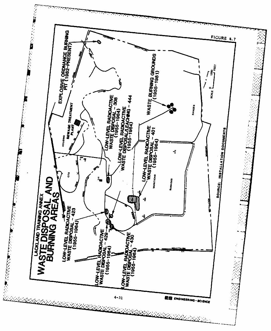
0r PmwY-03 co
3zj)
CDza ecolavo
a! ui z
cogLug
z In &d tto3
co
4,.l12-
ca Q
Q <LbU~ .
co c.,. .
o< h
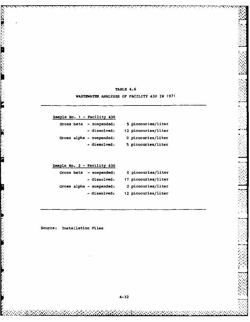
TABLE 4.6
WASTEWATER ANALYSES OF FACILITY 430 IN 1971
Sample no. 1 -Facility 430
Gross beta - suspended: 5 picocuries/liter
- dissolved: 12 picocuries/literow.
Gross alpha - suspended: 0 picocuries/liter
-dissolved: 5 picocuries/liter
Sample No. 2 -Facility 430
Gross beta - suspended: 0 picocuries/liter
- dissolved: 17 picocuries/liter
Gross alpha - suspended: 0 picocuries/liter
- dissolved: 12 picocuries/liter
Source: Installation Files
4-32
apparently did not mention the 401 site and it is possible the rectangu-
lar-shaped 401 area was created after the AEC activities were termi-
nated. A field inspection of the 401 site in 1981 revealed a hole about
30 feet in diameter and 15 feet deep, but no other unusual features. A
former employee at the AEC site indicated that low-level radioactive
waste from Medina and other AEC facilities was buried in the vicinity of
the 401 area (either in the now-designated 401 area or west of it in
line with the 509 bunker as shown in Figure 4.7) in the time period 1961
to 1965. The waste was in wooden crates (about 4 feet by 4 feet by 8
feet) with radioactive signs on the exterior. The crates were excavated
in 1965 and removed from the area when the AEC ceased operations. The
volume of material buried or the extent of the contamination is not
known but reportedly it took several weeks to remove the crates.
The sixth area identified as having been used for low-level radio-
active waste was Facility 444. A former employee indicated a small
gravel leaching type area (about 20 feet by 20 feet) existed behind the
building. This apparently received intermittent wastewater discharges.
It was noted that the gravel and soil from this area was excavated and
removed from the Lackland TA when AEC left.
Waste Burning Sites
Two areas have served as waste burning sites and both are located
at the Lackland TA. A waste burning ground (Facility 815) operated from
1955 to 1981 and an explosive ordnance burning pit (Facility 805) has
been operating since 1982. These sites are shown in Figure 4.7.
The waste burning grounds is an area originally used by AEC and
later by the Air Force. During the AEC operations, outdated explosives
were burned at Facility 815. This area consisted of four circular
at-grade gravel sites on which materials were ignited. Some of the
materials reportedly burned included Composition B, Composition C4, TNT,
and detonators. Other unidentified materials were also burned during
the AEC operations including items brought to the Medina facility from
other AEC installations. The frequency of burning and quantity of
wastes disposed at the site were apparently quite variable. At times
material was accumulated and then burned once or twice per day for a
couple of weeks; on other occasions burning occurred one or two days per
week on a more regular weekly routine. Detonators were often ignited on
4-33
.. . . .
" . - - . . . . .- o -.K1
6
Friday and burned all weekend with copper residual being recovered at
the site after combustion. Typical quantities per burn on each circular
area of Facility 815 was several thousand pounds of explosives prior to
1966 and a lesser amount after that time.
Following the departure of AEC in 1966, the Facility 815 burning
grounds continued to be used until 1981 by Lackland Explosive Ordnance
Detachment personnel. In 1982 the SOD group abandoned the Facility 815
grounds and began using a new area at Facility 805. Burning at the
latter site takes place in a pit about 6 feet by 20 feet by 5 feet deep.
Explosives from other bases have been brought to the Lackland TA burning
sites for disposal. A wide variety of munitions and explosives have
been burned at these two sites by EOD including black powder; smokeless
powder; fulminate of mercury; PETN; Composition B; Composition C1, C2,
C3, and C4; dynamite, gelatin dynamite and TNT. Other items which are
burned include flares, small arms ammunition and blasting caps, and
aircraft starter cans containing propellants (from Kelly AFB). The
materials to be burned are placed on wooden pallets and ignited with
about 10 gallons of diesel fuel. The frequency of fires by the EOD
teams has typically been slightly less than once per month. The quan-
tity of material per burn has been variable depending upon the type of
items being disposed.
Leaching Areas
As noted in Table 4.1 and Figures 4.8 and 4.9, respectively, one
leaching area is located near Building 7595 at Lackland AFB and another
near Building 466 at the Lackland Training Annex. Both of these facil-
ities discharge the contents of the dip tanks used for military dogs
onto nearby soils on a monthly basis. These discharges are comprised of
about 200 gallons of flea and tick dip solution (pesticides in solution
with a solvent carrier). Although the type of dip solution has changed
periodically (every few years) current use includes Dermaton II, 10%
xylene (as a carrier) and 12% Supono (a dichlorophenyl diethyl phosphate
derived insecticide). The leaching area at Lackland AFB has been used
since about 1960 and at Lackland TA since about 1966.
Sanitary Sewerage System
Lackland AFB since its beginning has discharged its wastewater off
4-34 .... i
. . . . . .. . . . . . . . . . . . . . . . . . .
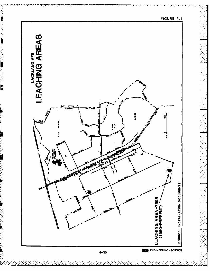
FIGURE '4.8
4
LEON
- WD-
doI-
Zc4cM w
4c R
435 Es ENGINEERING -SCIENCE4-35 . .
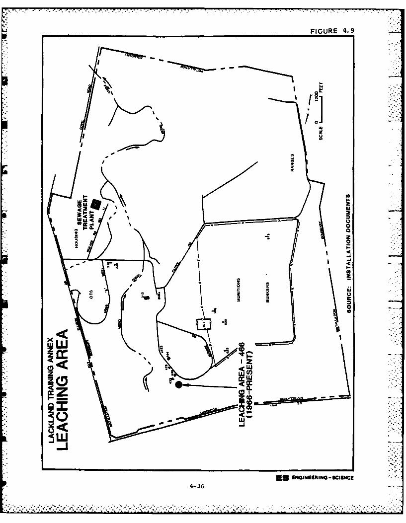
FIGURE 4.9
w~ -J
1k m
.1010]
4-3
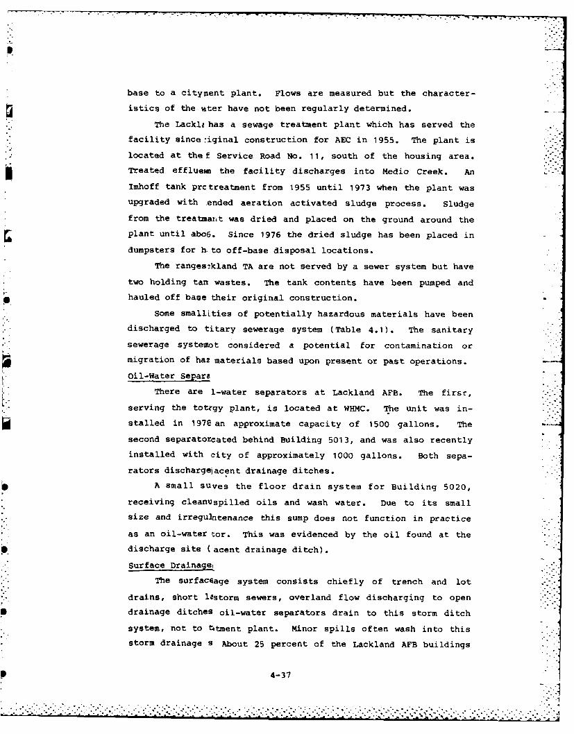
base to a cityment plant. Flows are measured but the character-
istics of the -ater have not been regularly determined.
The Lackli has a sewage treatment plant which has served the
facility since 7iginal construction for AEC in 1955. The plant is
located at the f Service Road No. 11, south of the housing area.
Treated effluetm the facility discharges into Medio Creek. An
Imhoff tank prctreatment from 1955 until 1973 when the plant was
upgraded with ended aeration activated sludge process. Sludge
from the treatmait was dried and placed on the ground around the
plant until abo6. Since 1976 the dried sludge has been placed in
dumpsters for h. to off-base disposal locations.
The ranges:kland TA are not served by a sewer system but have
two holding tan wastes. The tank contents have been pumped and
hauled off base their original construction.
Some smallLties of potentially hazardous materials have been
discharged to titary sewerage system (Table 4.1). The sanitary
sewerage systemot considered a potential for contamination or
migration of ha2 materials based upon present or past operations.
Oil-Water Separa
There are 1-water separators at Lackland AFB. The first,
serving the totzgy plant, is located at WHMC. The unit was in-
stalled in 1978 an approximate capacity of 1500 gallons. The
second separatorcated behind Building 5013, and was also recently
installed with city of approximately 1000 gallons. Both sepa-
rators dischargelacent drainage ditches.
A small suves the floor drain system for Building 5020,
receiving cleanuspilled oils and wash water. Due to its small
size and irreguIntenance this sump does not function in practice
as an oil-water tor. This was evidenced by the oil found at the
discharge site (acent drainage ditch).
surface Drainage.
The surfaceage system consists chiefly of trench and lot
drains, short lastorm sewers, overland flow discharging to open
drainage ditches oil-water separators drain to this storm ditch
system, not to t tment plant. Minor spills often wash into this
storm drainage s About 25 percent of the Lackland AFB buildings
4-37
drain to a storm sewer that discharges to Leon Creek. The rest of the
base drains into open drainage ditches which also discharge into Leon
Creek (see Figure 3.2). A portion of the base also drains westward in
an overland flow. Most areas of concern at the Lackland Training Annex
drain to Medio Creek (Figure 3.3). A portion of the range areas drain
to unnamed trib..taries of the Medina River.
Consider.Lng the types and quantities of materials discharged to the
surface drainage systems, the greatest potential for contamination and
migration is from the discharge of the oil-water separators and spill
materials going to the drainage system.
Incinerators
The Wilford Hall Medical Center (WHMC) utilizes an incinerator to
dispose of pathological wastes. This practice dates back at least to
the mid-1950's. The old incinerator operated from the roof of WHMC, but Sits capacity was insufficient. The new incinerator (1980 to present) is
located close to WHMC (Building 3558) and operates five days a week,
year-round. Ashes are disposed of at the landfill adjacent to Leon
Creek (see Table 4.1).
EVALUATION OF PAST DISPOSAL ACTIVITIES AND FACILITIES
Review of past waste generation and management practices at Lack-
land AFB has resulted in identification of 31 sites and/or activities
which were considered as areas of concern for potential contamination
and mig- tion of contaminants.
Sites Eliminated from Further Evaluation
The sites of initial concern were evaluated using the Flow Chart
presented in Figure 1.2. Sites not considered to have a potential for
contamination were deleted from further evaluation. The sites which
have potential for contamination and migration of contaminants were
evaluated using the Hazard Assessment Rating Methodology (HARM). Table
4.7 summarizes the results of the flow chart logic for each of the areas
of initial concern.
Twenty-four of the 31 sites assessed did not warrant further eval-
uation. The rationale for omitting these sites from HARM evaluation is
discussed below.
4-38 .
. . . . . . . .. . . . . . . . . . . . .
.- . . . . . . . .."- .- .' . . . . . . ....-. .'. ." .'+'''- '-. -< I- . .. . -L- L.. .. L ,- •. .- ..i 5-L-.-. ,.. + . . -,. ++ . + +
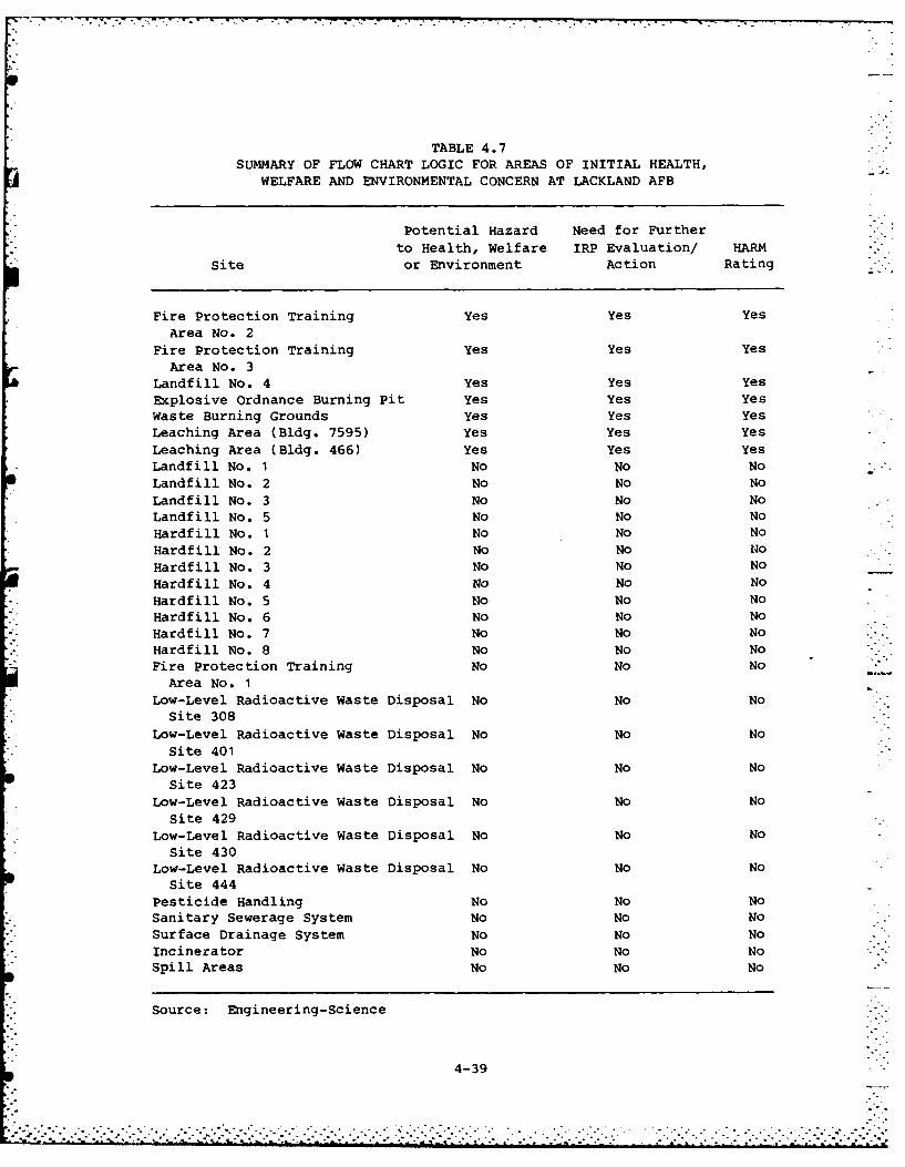
TABLE 4.7SUMMARY OF FLOW CHART LOGIC FOR AREAS OF INITIAL HEALTH,
WELFARE AND ENVIRONMENTAL CONCERN AT LACKLAND AFB
Potential Hazard Need for Further
to Health, Welfare IRP Evaluation/ HARM
Site or Environment Action Rating
Fire Protection Training Yes Yes Yes
Area No. 2Fire Protection Training Yes Yes Yes
Area No. 3
Landfill No. 4 Yes Yes Yes
Explosive Ordnance Burning Pit Yes Yes YesWaste Burning Grounds Yes Yes Yes
Leaching Area (Bldg. 7595) Yes Yes Yes
Leaching Area (Bldg. 466) Yes Yes Yes
Landfill No. 1 No No No
Landfill No. 2 No No No
Landfill No. 3 No No NoLandfill No. 5 No No No
Hardfill No. 1 No No No
Hardfill No. 2 No No No
Hardfill No. 3 No No No
Hardfill No. 4 No No No
Hardfill No. 5 No No No
Hardfill No. 6 No No No
Hardfill No. 7 No No NoHardfill No. 8 No No No
Fire Protection Training No No NoArea No. 1
Low-Level Radioactive Waste Disposal No No NoSite 308
Low-Level Radioactive Waste Disposal No No No
Site 401Low-Level Radioactive Waste Disposal No No No
Site 423
Low-Level Radioactive Waste Disposal No No No
Site 429Low-Level Radioactive Waste Disposal No No No
Site 430
Low-Level Radioactive Waste Disposal No No NoSite 444
Pesticide Handling No No No
Sanitary Sewerage System No No NoSurface Drainage System No No No
Incinerator No No NoSpill Areas No No No
Source: Engineering-Science
4-39
-.. :i:: ... .. ~ i.-.-, . o, .% ° ° .- o °. . . . 0 ° 0 , ° . , ., ° . ° ° . , ..', , . . - . , . ,, . -. , ,° .-. - --. . . . .
Landfill Nos. 1, 2, 3 and 5 have received little if any industrial/
shop wastes. Nearly all materials disposed have been normal base solid
waste such as garbage, refuse, etc. Similarly, all hardfill areas (Nos.
1-8) have received only construction and demolition materials, such as
wood, scrap metal and other bulky wastes. There is no evidence that any
of these landfills and hardfills have the potential to create environ-
mental contamination.
FPTA No. 1 was used periodically in the 1950's and 1960's. How-
ever, when the facility was discontinued major construction occurred on
the site including significant regrading and possibly the removal of
some soils from the site. Due to the small quantities of material
burned and the disturbed nature of the site, it is concluded that mini-
mal potential for contamination exists.
The low-level radioactive waste disposal sites which existed during
the AEC operations were all inspected and provided environmental clear-
ances when the Air Force took over the site. One site not included
(near Facility 444) in the listing to Air Force Real Property had all
the soil removed from it and taken off the installation according to a
former AEC employee. There is no indication from records or employee
interviews that radioactive wastewater tanks (Facility 308, 429 and 430)
were suspected to leak. A sample from one tank indicated low level
radioactive wastewater. All material buried in the 401 area was removed
from the area. The AEC testing and clearances on the Lackland TA in-
cluded both 401 and 444 disposal sites. Based upon the available infor-
mation, it is concluded the low-level radioactive waste disposal sites
do not pose a potential for contamination.
Review of the pesticide handling operations and the einsing and
mixing sites does not indicate a potential source of coaitamin.-tion or
migration. The suspected disposal of pesticides to Landfill No. 4 is
considered as a part of the evaluation of that disposal site.
Wastewaters sent to the sanitary sewerage system at Lackland AFB
have been transported in closed conduits off-base for its entire his-
tory. Wastewater has been treated at the Lackland TA plant and dis-
charged to Medio Creek since the original AEC operations. The sanitary
sewerage system is not considered a potential source of contamination.
4-40
The surface drainage system receives some minor spillage of waste
materials from building operations and from oil-water separators.
Discharge of waste to the surface drainage system is believed to be
infrequent and minimal potential for contamination exist.
Ash from the Wilford Hall incinerator has been disposed in the base
landfills or hardfills. The incinerator operation and ash disposal is
not a potential source of contamination.
Oil releases to the ground and drainage areas near Buildings 4902
and 5020 do not represent good practice but the potential for environ-
mental contamination is considered minimal. The reported one gallon
spill of PCB capacitor oil and subsequent removal of soil does not
represent a potential for contamination. The fuel tank truck explosion
and fuel loss do not represent a potential contamination site.
Sites Evaluated Using HARM
The remaining seven sites identified in Table 4.7 were evaluated
using the Hazard Assessment Rating Methodology. The HARM process takes
into account characteristics of potential receptors, waste character-
istics, pathways for migration, and specific characteristics of the site
related to waste management practices. Results of the HARM analysis for
the sites are summarized in Table 4.8.
The procedures used in the HARM system are outlined in Appendix G
and the specific rating forms for the seven sites at Lackland AFB are
presented in Appendix H. The HARM system is designed to indicate the
relative need for follow-on action.
4-41 V S S 5 - , .°- % .
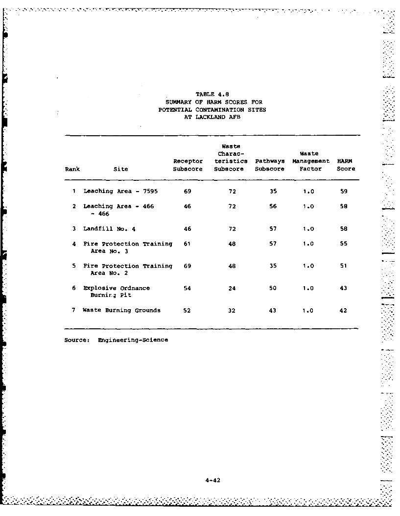
TABLE 4.8SUMMARY OF HARM SCORES FOR
POTENTIAL CONTAMINATION SITESAT LACKLAND AFB
WasteCharac- Waste
Receptor teristics Pathways Management HARMRank Site Subscore Subecore Subscore Factor Score
1 Leaching Area - 7595 69 72 35 1.0 59
2 Leaching Area - 466 46 72 56 1.0 58
- 466
3 Landfill No. 4 46 72 57 1.0 58
4 Fire Protection Training 61 48 57 1.0 55Area No. 3
5 Fire Protection Training 69 48 35 1.0 51Area No. 2
6 Explosive Ordnance 54 24 50 1.0 43Burnir; Pit -
7 Waste Burning Grounds 52 32 43 1.0 42
Source: Engineering-Science
4-42
o- - - -. .. . . . .. * .. . . . . . . .
SECTION 5
CONCLUS IONS
The goal of the IRP Phase I study is to identify sites where there
is potential for environmental contamination resulting from past waste
disposal practices and to assess the probability of contamination migra-
tion from these sites. The conclusions given below are based on field
inspections; review of records and files; review of the environmental
setting; interviews with base personnel, past employees and local, state
and federal government employees; and assessments using the HARM system.
Table 5.1 contains a list of the potential contamination sources ident-
if led at Lackland AFB and a summary of the HARM scores for those sites.
LEACHING AREA - 7595
This site at Lackland AFB has sufficient potential to create envi-
ronmental contamination and follow-on investigation is warranted. This
leaching area has routinely received discharges of spent pesticide solu-
tions from the dog training facilities at Lackland AFB since about 1960.
The solutions have varied through the years. The receptor and waste
characteristics subscores have contributed to the total HARM score of
59.
LEACHING AREA - 466
This leaching area at Lackland TA has sufficient potential to
create environmental contamination and follow-on investigation is justi-
fied. The site has regularly had spent pesticide solutions from dog
training activities discharged to it. This operation has been active
since the Air Force took over the Medina facility from AEC in 1966. The
waste characteristic and pathway subscores primarily contributed to the
HARM score of 58.
5-1-.- .-..
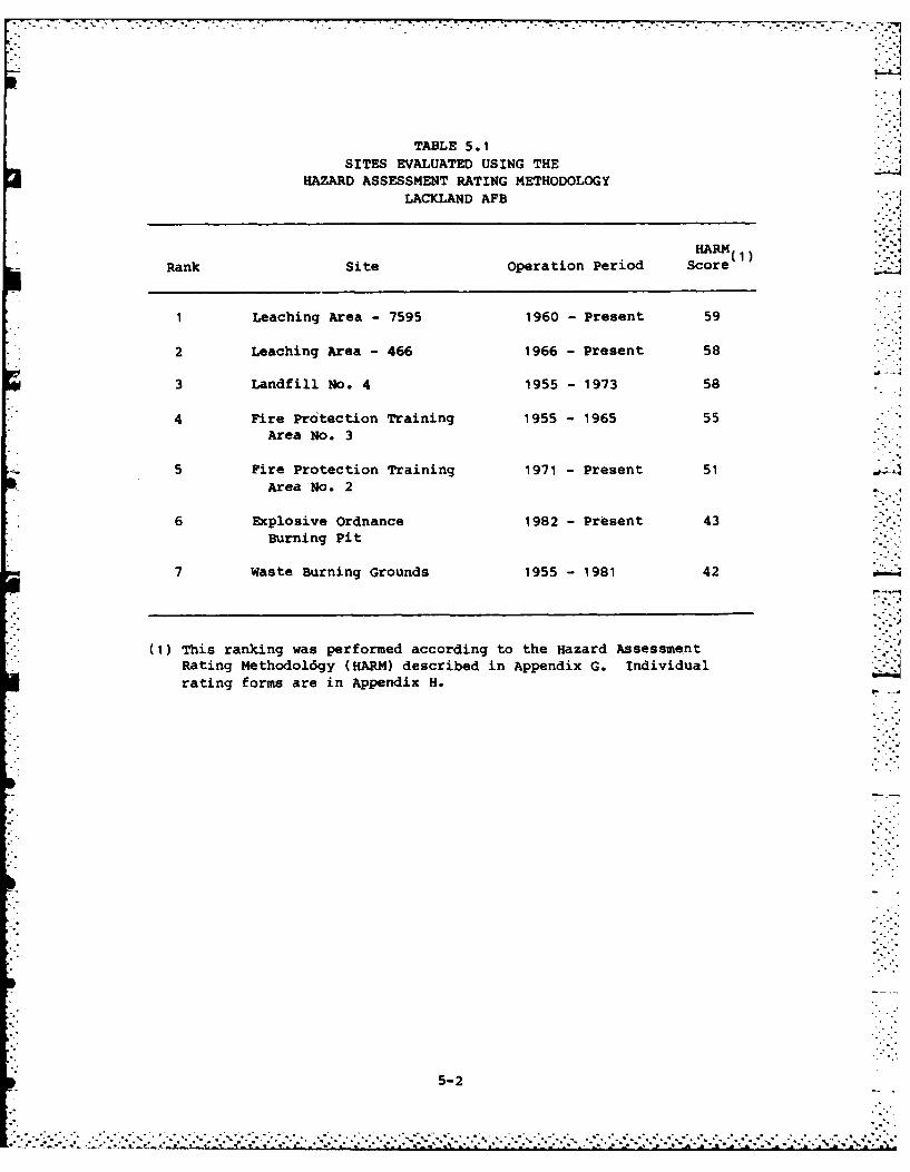
TABLE 5.1 .
SITES EVALUATED USING THEHAZARD ASSESSMENT RATING METHODOLOGY
LACKLAND AF13
HARMRank Site operation Period Score(1 _
1 Leaching Area -7595 1960 -Present 59
2 Leaching Area - 466 1966 - Present 58
3 Landfill No. 4 1955 -1973 58
4 Fire Protection Training 1955 -1965 55Area No. 3
5 Fire Protection Training 1971 -Present 51Area No. 2 .
6 Explosive ordnance 1982 -Present 43Burning Pit
7 Waste Burning Grounds 1955 -1981 42
(1) This ranking was performed according to the Hazard AssessmentRating Methodoidgy (HARM) described in Appendix G. Individualrating forms are in Appendix H.-
5-2
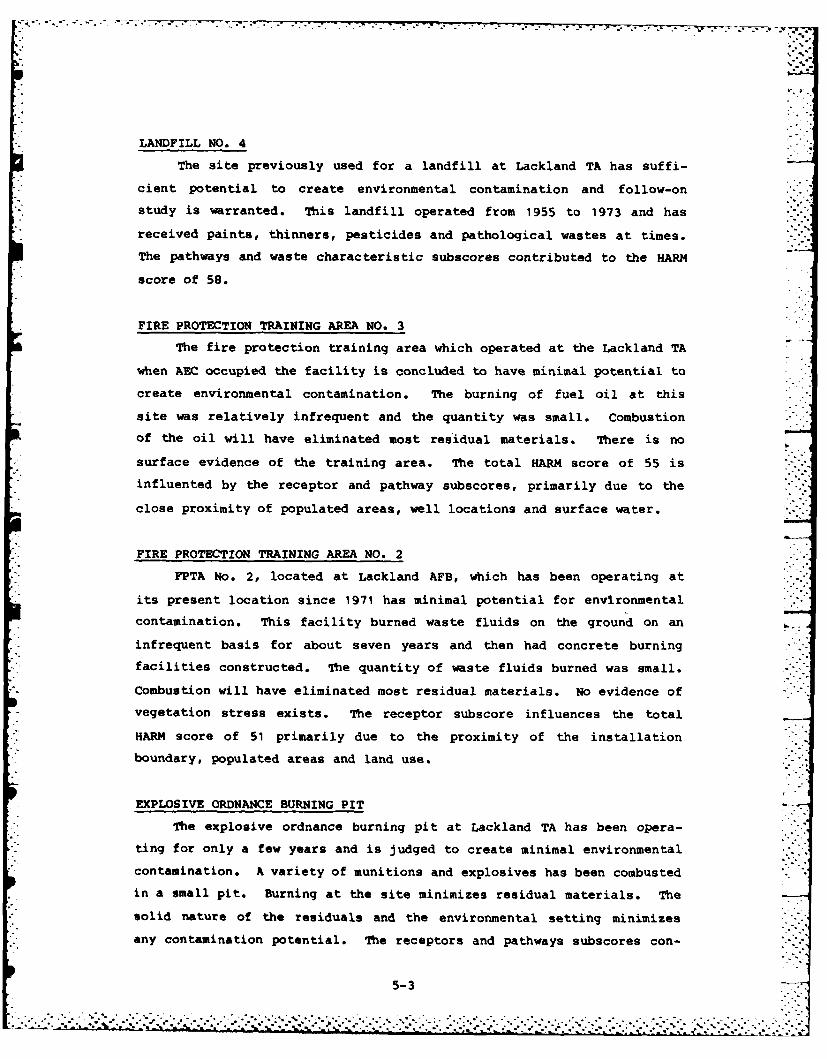
LANDFILL NO. 4
The site previously used for a landfill at Lackland TA has suffi-
cient potential to create environmental contamination and follow-on
study is warranted. This landfill operated from 1955 to 1973 and has
received paints, thinners, pesticides and pathological wastes at times.
The pathways and waste characteristic subscores contributed to the HARM
score of 58.
FIRE PROTECTION TRAINING AREA NO. 3
The fire protection training area which operated at the Lackland TA
when ABC occupied the facility is concluded to have minimal potential to
create environmental contamination. The burning of fuel oil at this
site was relatively infrequent and the quantity was small. Combustion
of the oil will have eliminated most residual materials. There is no
surface evidence of the training area. The total HARM score of 55 is
influented by the receptor and pathway subscores, primarily due to the
close proximity of populated areas, well locations and surface water.
FIRE PROTECTION TRAINING AREA NO, 2
FPTA No. 2, located at Lackland AFB, which has been operating at
its present location since 1971 has minimal potential for environmental
contamination. This facility burned waste fluids on the ground on an
infrequent basis for about seven years and then had concrete burning
facilities constructed. The quantity of waste fluids burned was small.
Combustion will have eliminated most residual materials. No evidence of
vegetation stress exists. The receptor subscore influences the total
HARM score of 51 primarily due to the proximity of the installation
boundary, populated areas and land use.
EXPLOSIVE ORDNANCE BURNING PIT
The explosive ordnance burning pit at Lackland TA has been opera-
ting for only a few years and is judged to create minimal environmental
contamination. A variety of munitions and explosives has been combusted
in a small pit. Burning at the site minimizes residual materials. The
solid nature of the residuals and the environmental setting minimizes
any contamination potential. The receptors and pathways subscores con-
5-3
tribute to the HARM score of 43, mainly due to the deep ground water
supply and surface water quality.
WASTE BURNING GROUNDS
The burning grounds at the Lackland TA, which functioned for both
Air Force and AEC waste explosive combustion, has minimal potential to
create ertvironmental contamination. The burning procedures have mini-
mized residual materials. The remaining solid residuals, when coupled
with the environmental setting, minimizes any contamination potential. -
The receptors subscore primarily influences the total HARM score of 42
due to the deep ground water supply and surface water quality.
5-4
•. .-o"
- .... ..** '* .. o .*o
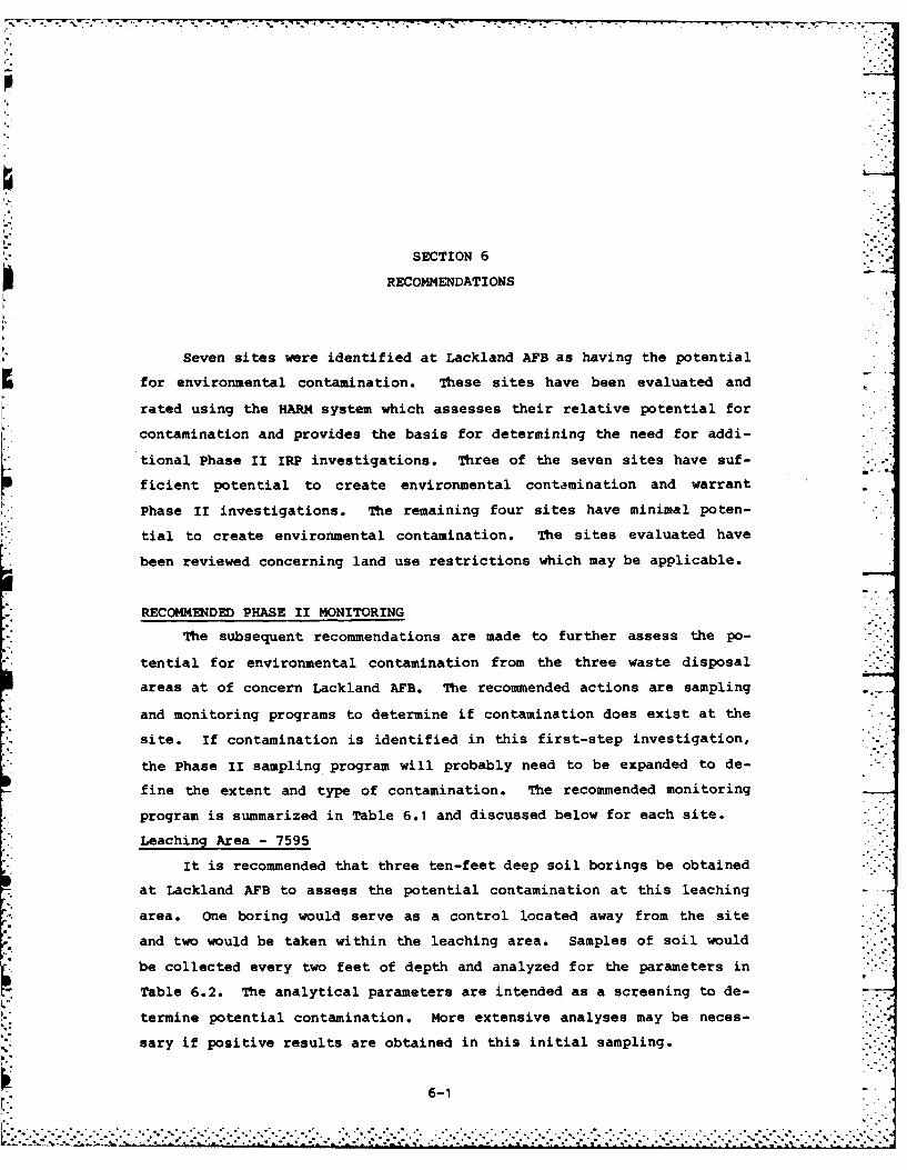
SECTION 6
RECOMMENDATIONS
Seven sites were identified at Lackland AFB as having the potential
for environmental contamination. These sites have been evaluated and
rated using the HARM system which assesses their relative potential for
contamination and provides the basis for determining the need for addi-
tional Phase II IRP investigations. Three of the seven sites have suf-
ficient potential to create environmental contamination and warrant
Phase II investigations. The remaining four sites have minimal poten-
tial to create environmental contamination. The sites evaluated have
been reviewed concerning land use restrictions which may be applicable.
RECOMMENDED PHASE II MONITORING
The subsequent recommendations are made to further assess the po-
tential for environmental contamination from the three waste disposal
areas at of concern Lackland AFB. The recommended actions are sampling
and monitoring programs to determine if contamination does exist at the
site. If contamination is identified in this first-step investigation,
the Phase II sampling program will probably need to be expanded to de-
fine the extent and type of contamination. The recommended monitoring
program is summarized in Table 6.1 and discussed below for each site.
Leaching Area - 7595
It is recommended that three ten-feet deep soil borings be obtained
at Lackland AFB to assess the potential contamination at this leaching
area. one boring would serve as a control located away from the site
and two would be taken within the leaching area. Samples of soil would
be collected every two feet of depth and analyzed for the parameters inKrTable 6.2. The analytical parameters are intended as a screening to de-
termine potential contamination. More extensive analyses may be neces-
sary if positive results are obtained in this initial sampling.
6-1
2. .... ]
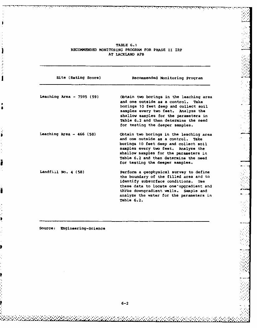
TABLE 6.1RECOMMENDED MONITORING PROGRAM FOR PHASE II IRP
AT LACKLAND AFB
Site (Rating Score) Recommended Monitoring Program
Leaching Area - 7595 (59) Obtain two borings in the leaching areaand one outside as a control. Takeborings 10 feet deep and collect soilsamples every two feet. Analyze theshallow samples for the parameters inTable 6.2 and then determine the needfor testing the deeper samples.
Leaching Area - 466 (58) Obtain two borings in the leaching areaand one outside as a control. Takeborings 10 feet deep and collect soilsamples every two feet. Analyze theshallow samples for the parameters inTable 6.2 and then determine the needfor testing the deeper samples.
Landfill No. 4 (58) Perform a geophysical survey to definethe boundary of the filled area and toidentify subsurface conditions. Usethese data to locate one'upgradient andthir-ee downgradient wells. Sample andanalyze the water for the parameters inTable 6.2.
Source: Engineering-Science
6-2
* V --* --
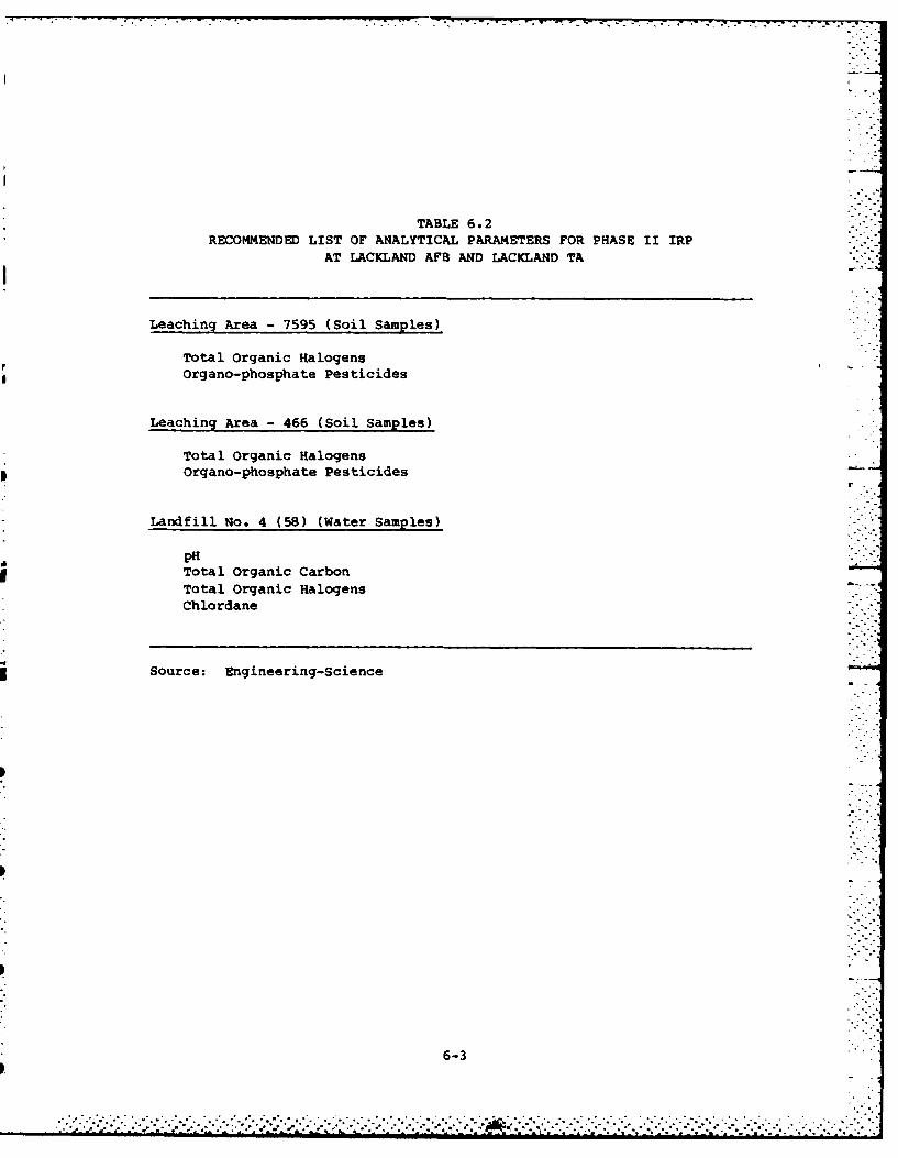
TABLE 6.2RECOMMENDED LIST OF ANALYTICAL PARAMETERS FOR PHASE II IRP
AT LACKLANI) AFB AND LACKLAND TA
Leaching Area -7595 (Soil Samples)
Total organic HalogensOrgano-phosphate Pesticides
Leaching Area - 466 (Soil Samples)
Total Organic Halogensm Organo-phosphate Pesticides
Landfill No. 4 (58) (Water Samples)
pHTotal Organic CarbonTotal Organic HalogensChlordane
Source: Engineering-Science
6-3
Leaching Area - 466
Three ten-foot deep borings are recommended for this Lackland TA
site to assess potential contamination. One boring would serve as a
control and the other two would be taken in the leaching area. Samples
of soil taken every two feet of depth would be analyzed (Table 6.2).More extensive tests may be needed depending on the initial results.
Landfill No. 4
Four monitoring wells are recommended for installation at this
landfill site at Lackland TA. A geophysical survey of the site will
define the boundaries and assist in locating the monitoring wells. One
upgradient well would be used as a control point for the three
downgradient units. Table 6.2 outlines parameters proposed to screen
the potential contamination from the site. Additional analyses may be
needed if the initial testing shows positive results.
RECOMMENDED GUIDELINES FOR LAND USE RESTRICTIONS
It is desirable to have land use restrictions for the identified
sites to (1) provide continued protection of human health, welfare, and
environment, (2) insure that migration of potential contaminants is not
promoted through improper land uses, (3) facilitate compatible develop-
ment of future USAF facilities and (4) allow identification of property
which may be proposed for excess or outlease.
The recommended guidelines for land use restrictions at each iden-
tified disposal site at Lackland AFB are presented in Table 6.3. A
description of the land use restriction guidelines is included in Table
6.4. Land use restrictions at sites recommended for on-site monitoring
should be re-evaluated upon completion of the Phase II program and
appropriate changes made.
6-4
C ,°C C-,
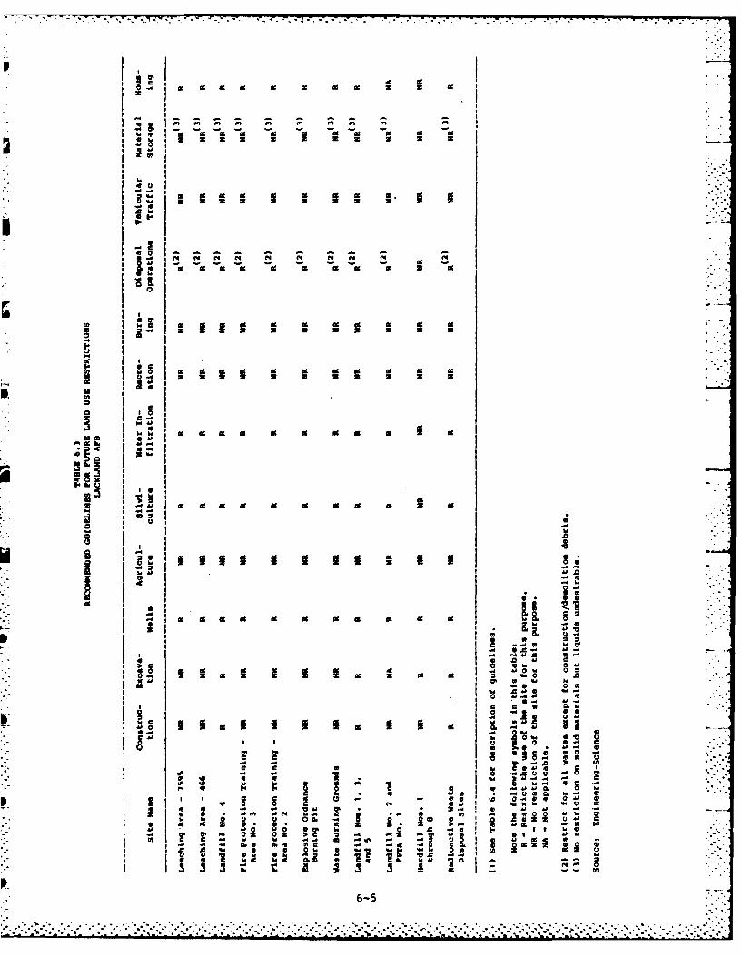
od 1% dc dc z
I I
IdW
4J 1 0 3 U B 3
I -Ai .0I I --
i N ~~ N0 N N N N
-4 II~61
13 %db. 6.
IN -1-5

TABLE 6.4DESCRIPTION OF GUIDELINES FOR LAND USE RESTRICTIONS
Guideline Description
Construction on the site Restrict the construction of structureswhich make permanent (or semi-permanent)and exclusive use of a portion of thesite's surface.
Excavation Restrict the disturbance of the cover orsubsurface materials.
Well construction on or Restrict the placement of any wellsnear the site (except for monitoring purposes) on or
within a reasonably safe distance of thesite. This distance will vary from siteto site, based on prevailing soil con-ditions and ground-water flow. -
Agricultural use Restrict the use of the site for agri-cultural purposes to prevent food chaincontamination.
Silvicultural use Restrict the use of the site for silvi-cultural uses (root structures coulddisturb cover or subsurface materials).
Water infiltration Restrict water run-on, ponding and/orirrigation of the site. Water infiltra-tion could produce contaminated leachate.
Recreational use Restrict the use of the site forrecreational purposes.
Burning or ignition sources Restrict any and all unnecessary sourcesof ignition, due to the possible presenceof flammable compounds.
Disposal operations Restrict the use of the site for wastedisposal operations, whether above or
below ground.
Vehicular traffic Restrict the passage of unnecessaryvehicular traffic on the site due to thepresence of explosive material(s) and/orof an unstable surface.
Material storage Restrict the storage of any and allliquid or solid materials on the site.
Housing on or near the site Restrict the use of housing structures onor within a reasonably safe distance ofthe site. L_
6-6 L
• .° ''.-' -. " -. . ,: - " "-. -.°-"%".. ." .""" .""J ". """. '- .., '. '*j mc...., -. - .- ; ,.. . % .- .. . -. ,. - . . . • , 'L -
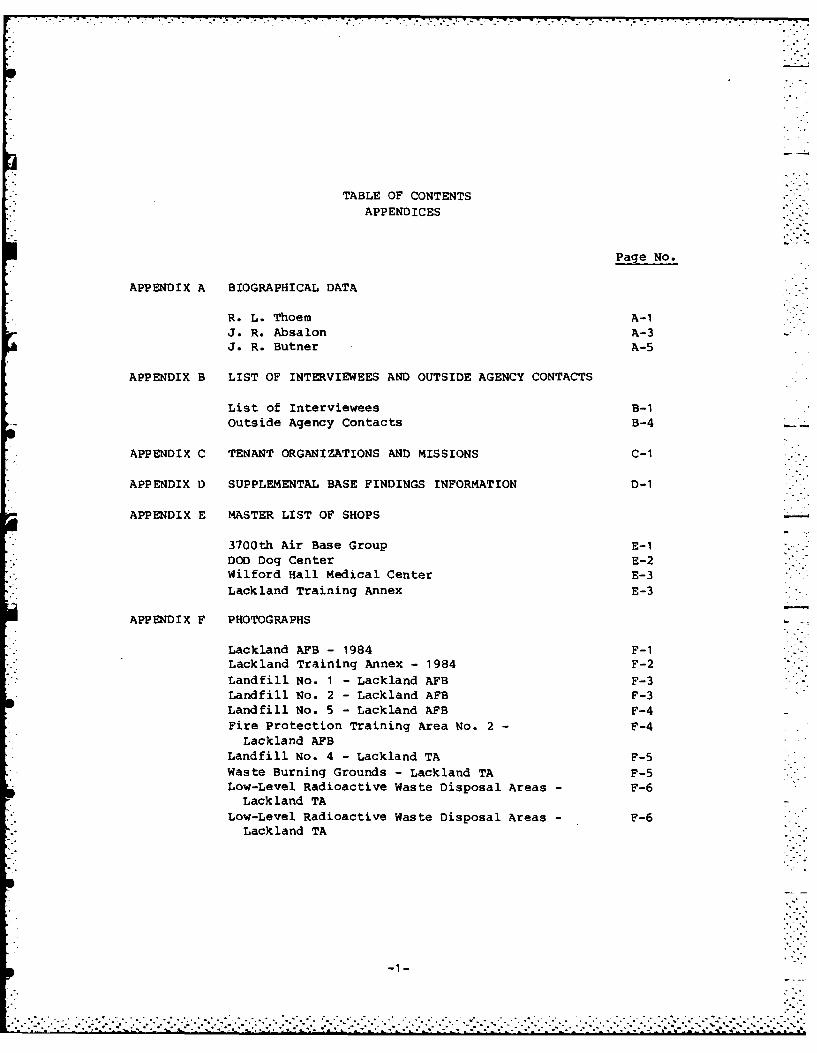
TABLE OF CONTENTSAPPENDICES
Page No.
APPENDIX A BIOGRAPHICAL DATA
R. L. Thoem A-iJ. R. Absalon A-3J. R. Butner A-5
APPENDIX B LIST OF INTERVIEWEES AND OUTSIDE AGENCY CONTACTS
List of Interviewees B-iOutside Agency Contacts B-4
APPENDIX C TENANT ORGANIZATIONS AND MISSIONS C-i
APPENDIX D SUPPLEMENTAL BASE FINDINGS INFORMATION D-I
APPENDIX E MASTER LIST OF SHOPS
3700th Air Base Group E-1DOD Dog Center E-2Wilford Hall Medical Center E-3Lackland Training Annex E-3
APPENDIX F PHOTOGRAPHS
Lackland AFB - 1984 F-iLackland Training Annex - 1984 F-2Landfill No. i - Lackland AFB F-3Landfill No. 2 - Lackland AFB F-3Landfill No. 5 - Lackland AFB F-4Fire Protection Training Area No. 2 - F-4
Lackland AFBLandfill No. 4 - Lackland TA F-5Waste Burning Grounds - Lackland TA F-5Low-Level Radioactive Waste Disposal Areas - F-6
Lack land TALow-Level Radioactive Waste Disposal Areas - F-6
Lackland TA
---
. . . . . .... . . . . . . . . . . . . . . .
TABLE OF CONTENTS(Continued)
APPENDIX G USAF INSTALLATION RESTORATION PROGRAM G-1
HAZARD ASSESSMENT RATING METHODOLOGY
APPENDIX H SITE HAZARD ASSESSMENT RATING FORMS
Leaching Area - 7595 H-I
Leaching Area - 466 H-3Landfill No. 4 H-5Fire Protection Training Area No. 3 H-7Fire Protection Training Area No. 2 H-9
Explosive Ordnance Burning Pit H-11Waste Burning Grounds H-13
APPENDIX I GLOSSARY OF TERMINOLOGY AND ABBREVIATIONS I-I
APPENDIX J REFERENCES J-1
APPENDIX K INDEX OF REFERENCES TO POTENTIAL CONTAMINATION K-ISITES AT LACKLAND AFB
-2-
*.. . . . . . . .. . . . . . . . .
APPENDIX A
BIOGRAPHICAL DATA
.~~7 Z4.
.......
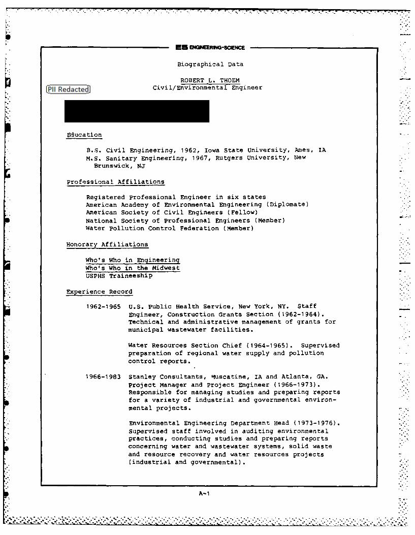
- rr..
EU e0 ERING-SCENCE
Biographical Data
ROBERT L. THOEMCivil/Environmental Engineer
Education
B.S. Civil Engineering, 1962, Iowa State University, Ames, IAM.S. Sanitary Engineering, 1967, Rutgers University, New
Brunswick, NJ
Professional Affiliations
Registered Professional Engineer in six statesAmerican Academy of Environmental Engineering (Diplomate)American Society of Civil Engineers (Fellow)
National Society of Professional Engineers (Member)Water Pollution Control Federation (Member)
Honorary Affiliations
Who's Who in Engineering
Who's Who in the MidwestUSPHS Traineeship
Experience Record
1962-1965 U.S. Public Health Service, New York, NY. StaffEngineer, Construction Grants Section (1962-1964).Technical and administrative management of grants formunicipal wastewater facilities.
Water Resources Section Chief (1964-1965). Supervised
preparation of regional water supply and pollutioncontrol reports.
1966-1983 Stanley Consultants, Muscatine, IA and Atlanta, GA.Project Manager and Project Engineer (1966-1973).Responsible for managing studies and preparing reportsfor a variety of industrial and governmental environ-mental projects.
Environmental Engineering Department Head (1973-1976).Supervised staff involved in auditing environmentalpractices, conducting studies and preparing reportsconcerning water and wastewater systems, solid wasteand resource recovery and water resources projects(industrial and governmental).
A-1
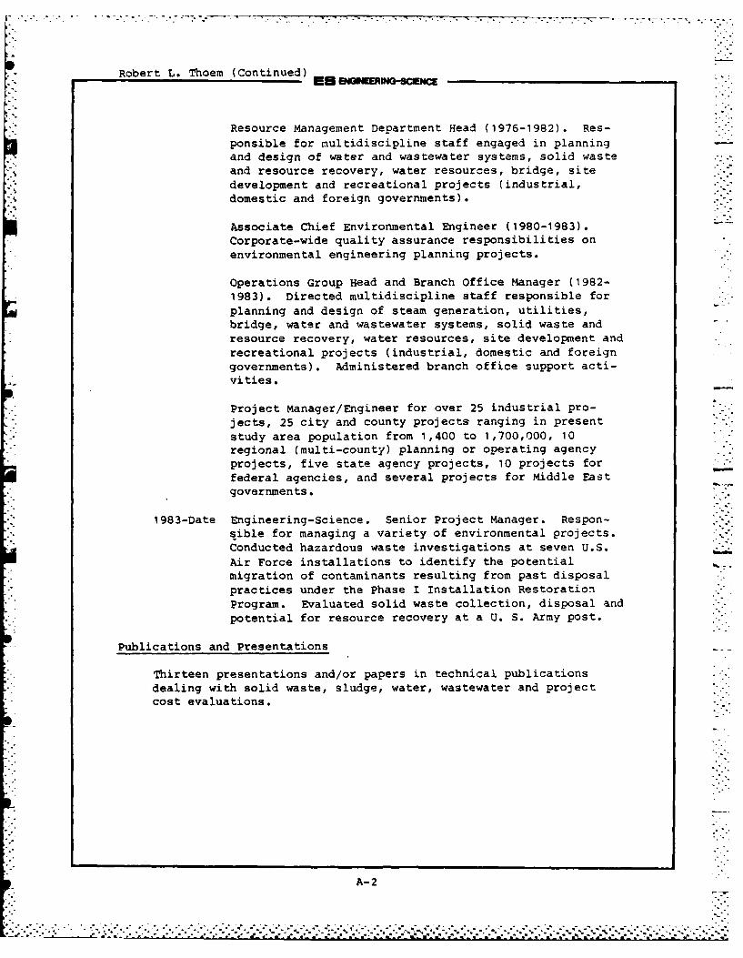
Robert L. Thoem (Continued) EUNEMRING-scNCE
Resource Management Department Head (1976-1982). Res-
ponsible for multidiscipline staff engaged in planningand design of water and wastewater systems, solid wasteand resource recovery, water resources, bridge, sitedevelopment and recreational projects (industrial,domestic and foreign governments).
Associate Chief Environmental Engineer (1980-1983).Corporate-wide quality assurance responsibilities onenvironmental engineering planning projects.
Operations Group Head and Branch Office Manager (1982-1983). Directed multidiscipline staff responsible forplanning and design of steam generation, utilities,bridge, water and wastewater systems, solid waste andresource recovery, water resources, site development andrecreational projects (industrial, domestic and foreigngovernments). Administered branch office support acti-vities.
Project Manager/Engineer for over 25 industrial pro-jects, 25 city and county projects ranging in presentstudy area population from 1,400 to 1,700,000, 10regional (multi-county) planning or operating agencyprojects, five state agency projects, 10 projects forfederal agencies, and several projects for Middle Eastgovernments.
1983-Date Engineering-Science. Senior Project Manager. Respon-sible for managing a variety of environmental projects.Conducted hazardous waste investigations at seven U.S.Air Force installations to identify the potentialmigration of contaminants resulting from past disposalpractices under the Phase I Installation RestorationProgram. Evaluated solid waste collection, disposal and
potential for resource recovery at a U. S. Army post.
Publications and Presentations
Thirteen presentations and/or papers in technical publicationsdealing with solid waste, sludge, water, wastewater and projectcost evaluations.
IL'
A-2
.....- o. . ..... . . . ........ .. ... 1 ...... . . ......... -
S m -RNG-SCENcE
Biographical Data
JOHN R. ABSALONHydrogeologist
Education
B.S. in Geology, 1973, Upsala College, East Orange, New Jersey
Professional Affiliations
Certified Professional Geologist (Indiana No. 46) (Virginia No. 241)Association of Engineering GeologistsGeological Society of AmericaNational Water Well Association
Experience Record
1973-1974 Soil Testing Incorporated-Drilling Contractors,Seymour, Connecticut. Geologist. Responsible forthe planning and supervision of subsurface investi-gations supporting geotechnical, ground-water con-tamination, and mineral exploitation studies in theNew England area. Also managed the office staff,drillers, and the maintenance shop.
1974-1975 William F. Loftus and Associates, Englewood Cliffs,New Jersey. Engineering Geologist. Responsible forplanning and management of geotechnical investigationsin the northeastern U.S. and Illinois. Other dutiesincluded formal report preparation.
1975-1978 U.S. Army Environmental Hygiene Agency, Fort Mc-Pherson, Georgia. Geologist. Responsible forperformance of'solid waste disposal facility sitingstudies, non-complying waste disposal site assess-ments, and ground-water monitoring programs at mili-tary installations in the southeastern U.S., Texas,and Oklahoma. Also responsible for operation andmanagement of the soil mechanics laboratory.
1978-1980 Law Engineering Testing Company, Atlanta, Georgia.Engineering Geologist/Hydrogeologist. Responsiblefor the project supervision of waste management, waterquality assessment, geotechnical, and hydrogeologicstudies at commercial, industrial, and government __7facilities. General experience included planning andmanagement of several ground-water monitoring programs,
A-3
John R. Absalon (Continued)
development of remedial action programs, and formula-tion of waste disposal facility liner system designrecommendations. Performed detailed ground-waterquality investigations at an Air Force installation inGeorgia, a paper mill in southwestern Georgia, andindustrial facilities in Tennessee.
1980-Date Engineering-Science. Hydrogeologist. Responsible
for supervising efforts in waste management, solidwaste disposal, ground-water contamination assessment,
leachate generation, and geotechnical and hydrogeo-logic investigations for clients in the industrial and
governmental sectors. Performed geologic investiga-tions at twelve Air Force bases and otherindustrialsites to evaluate the potential for migration of haz-ardous materials from past waste disposal practices.
Conducted RCRA ground-water monitoring studies for in- "dustrial clients and evaluated remedial action alterna-tives for a county landfill in Florida. Conductedquality management, hydrogeologic and ground-water
quality programs for the pulp and paper industry atseveral mills located in the Southeast United States.
Publications and Presentations
Eleven presentations and/or papers in technical publications or
conferences dealing with geology, ground water, and waste disposal/-ground water interaction.
A- 4
-~~~~~~~ ~~~~~~ . .. . .. . . .. . . . . . . . . . . . .. .. . . . .. . * t . . . . . . . . .... .b - ° .. . . . ... .. . . .... . . . .. . ... . . . . . ."
EU mEER-o-scE.c
SOMEOW40-SCIENCE -:
Biographical Data
JAMES R. BUTNER
Environmental Scientist
Education
B.S. Tulane University, Biological Sciences, 1976M.S. University of Florida, Environmental Engineering Sciences,
1983
Professional Affiliations
Water Pollution Control FederationSociety of Wetlands Scientists
Experience Record
1977-1979 Horticulturalist in the Horticultural industry inGainesville, Florida. Primary areas of experiencewere in botany, evaluation of the uses of native plantspecies, and business management.
1979-1981 Center for Wetlands, University of Florida. Hisinvolvement focused on evaluating the public healthaspects of wastewater recycling through wetlands, thesubject of his Master's thesis. Mr. Butner's otheractivities included modeling the survivorship ofpathogens in surface and ground waters, vegetationanalysis, and application of computer statisticalsoftware (SAS) to large data sets generated fromrevegetation studies of phosphate mined lands incentral Florida. Mr. Butner's coursework includedgraduate level courses in Environmental Chemistry,Nutrients and Eutrophication, Water ResourcesPlanning, Fortran Programming, Toxicology, EcologicalModeling and Statistics.
1982-1984 Claude Terry & Associates, Inc. (CTA). As anEnvironmental Scientist, his primary responsibilitieswere involved the collection, review and analysis oftechnical data and institutional issues associatedwith effluent discharge into wetlands. These dutieswere in conjunction with the production of a genericeight-state Environmental Impact Statement for RegionIV EPA entitled "Freshwater Wetlands for Wastewater
A-S
: ..:. ,L .: . -:: .-:, ,. :- :'. , :.. > -.: :'1 -1:->':.".:,:-- .-'.-'.",:-:":-'.-':-'-',- --'," .",: -:":'".:--:--:-.:":-'?'--'.".:-: :'i: .iA
ES EN M WrING-sCEc:E
James R. ButnerPage 2
Management". Other projects have involved conducting
environmental inventories and recommending mitigationto preserve and protect natural resources for otherEIS work. He was involved in the design of varioussampling programs, the collection, analysis, andinterpretation of chlorophyll and periphyton data aspart of the Georgia Statewide Nonpoint Source Study,and training laboratory personnel in wet chemistrytechniques.
1984-Present Engineering-Science, Inc. Environmental Scientistresponsible for the conduct of water and wastewatersampling programs and analyses, quality control,laboratory process evaluations, and evaluation ofother environmental assessment data. Involved in thedevelopment of environmental studies, inventories, andevaluations for municipal, industrial, and Federalgovernment projects.
Publications
Coauthor of the publication (1983), "Survival of Virus and EntericBacteria in Groundwater", Journal of Groundwater.
Paper entitled, "Freshwater Wetlands for Wastewater Management: Anintegrated framework for decision-making and wetlands protection",presented at the 1984 Research Triangle Conference on EnvironmentalTechnology, Raleigh, N.C., .rch 1984.
A-6
.. . . . . .. . . . . .
I , - ,- . . : ,. . . - .- ,- .. - . .. ._ _ . . _ _ . _ . , . S _ _ . - • - - -
p °
APPENDIX B
LIST OF INTERVIEWEES AND OUTSIDE AGENCY CONITACTS -
~~.
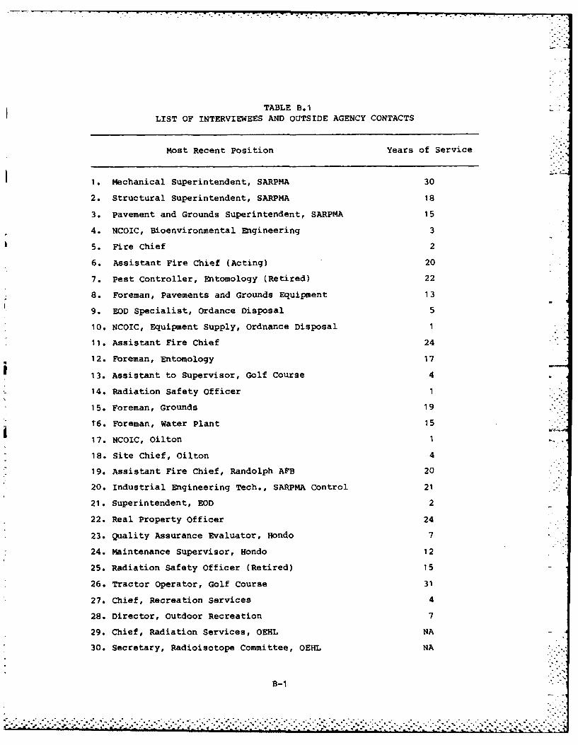
TABLE B.1
LIST OF INTERVIEWEES AND OUTSIDE AGENCY CONTACTS
Most Recent Position Years of Service .-
1. Mechanical Superintendent, SARPMA 30
2. Structural Superintendent, SARPMA 18
3. Pavement and Grounds Superintendent, SARPMA 15
4. NCOIC, Bioenvironmental Engineering 3
5. Fire Chief 2
6. Assistant Fire Chief (Acting) 20
7. Pest Controller, Entomology (Retired) 22
8. Foreman, pavements and Grounds Equipment 13
9. EOD Specialist, Ordance Disposal 5
10. NCOIC, Equipment Supply, Ordnance Disposal 1
11. Assistant Fire Chief 24
12. Foreman, Entomology 17
13. Assistant to Supervisor, Golf Course 4
14. Radiation Safety Officer 1
15. Foreman, Grounds 19
16. Foreman, Water Plant 15
17. NCOIC, Oilton 1
18. Site Chief, Oilton 4
19. Assistant Fire Chief, Randolph APB 20
20. Industrial Engineering Tech., SARPMA Control 21
21. Superintendent, EOD 2
22. Real Property Officer 24
23. Quality Assurance Evaluator, Hondo 7
24. Maintenance Supervisor, Hondo 12
25. Radiation Safety Officer (Retired) 15
26. Tractor Operator, Golf Course 31
27. Chief, Recreation Services 4
28. Director, Outdoor Recreation 7
29. Chief, Radiation Services, OEHL NA
30. Secretary, Radioisotope Committee, OEHL NA
B-1
. . . . .. . . . . . . .°.' .
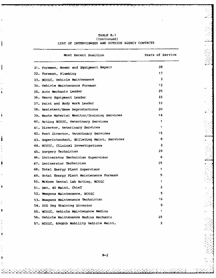
TABLE B.1
(Continued)
LIST OF INTERVIEWEES AND OUTSIDE AGENCY CONTACTS
Most Recent Position Years of Service
31. Foremen, Mower and Equipment Repair 28
32. Foreman, Plumbing 17
33. NCOIC, Vehicle Maintenance 2
34. Vehicle Maintenance Foreman 12
35. Auto Mechanic Leader 25
36. Heavy Equipment Leader 33
37. Paint and Body Work Leader 33
38. Assistant/Base Reproductions 20
39. Waste Material Monitor/Training Services 14
40. Acting NCOIC, Veterinary Services 1
41. Director, Veterinary Services 1
42. Past Director, Veterinary Services 15
43. Superintendent, Billeting Maint. Services 8
44. NCOIC, Clinical Investigations 2
45. Surgery Technician 29
46. Incinerator Technician Supervisor 6
47. Incinerator Technician 25
48. Total Energy Plant Supervisor 1
49. Total Energy Plant Maintenance Foreman 5
50. McKown Dental Lab Acting, NCOIC 1
51. Det. 40 Maint. Chief 2
52. Weapons Maintenance, NCOIC 5
53. Weapons Maintenance Technician 16
54. DOD Dog Training Director 9
55. NCOIC, Vehicle Maintenance Medina 1
56. Vehicle Maintenance Medina Mechanic 25
57. NCOIC, 6948th Mobility vehicle Maint. 2
B-2
".I . .-. .. ,- [-" ""? - -" ''' ''" '[ '".--"""- - - . "-""." , "/ - -' ." "°- " ' : ' : ''i"/ , ..
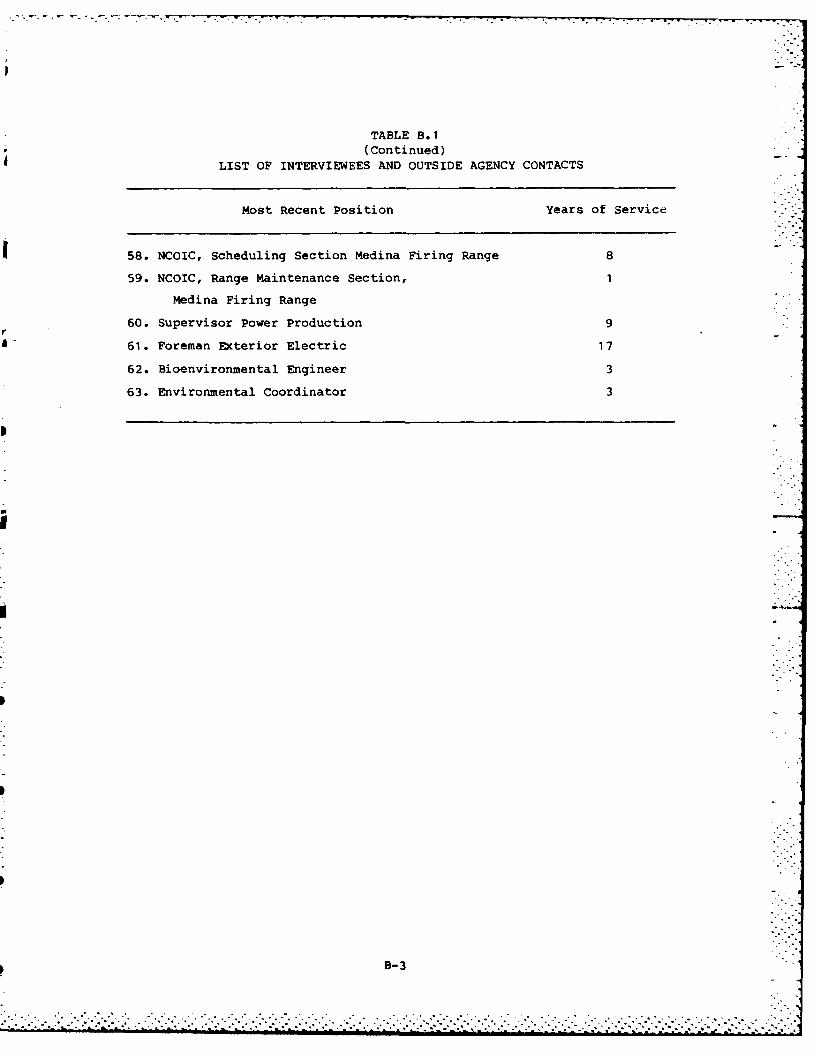
TABLE B.1(Continued)
LIST OF INTERVIEWEES AND OUTSIDE AGENCY CONTACTS
Most Recent Position Years of Service
58. NCOIC, Scheduling Section Medina Firing Range 8
59. NCOIC, Range Maintenance Section, 1
Medina Firing Range
60. Supervisor Power Production 9
61. Foreman Exterior Electric 17
62. Bioenvironmental Engineer 3
63. Environmental Coordinator 3
B-3•
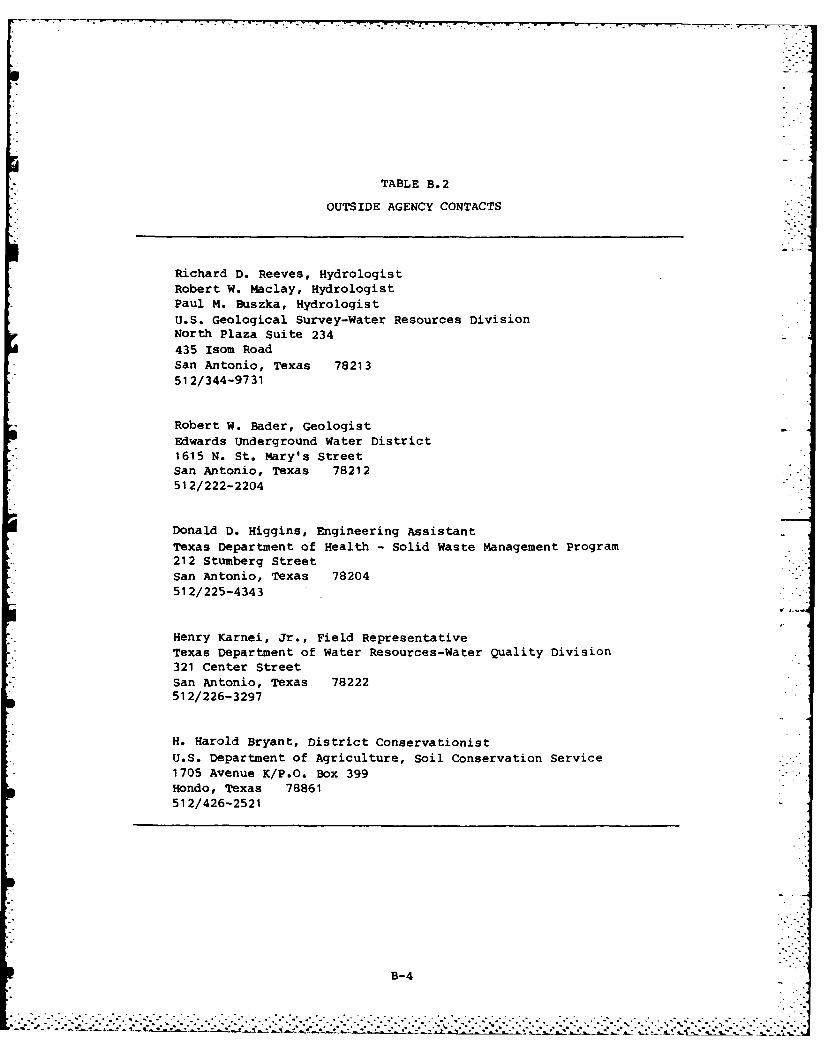
TABLE B.2
OUTSIDE AGENCY CONTACTS
Richard D. Reeves, HydrologistRobert W. Maclay, HydrologistPaul M. Buszka, HydrologistU.S. Geological Survey-Water Resources DivisionNorth Plaza Suite 234435 Isom RoadSan Antonio, Texas 78213512/344-9731
Robert W. Bader, GeologistEdwards Underground Water District1615 N. St. Mary's StreetSan Antonio, Texas 78212512/222-2204
Donald D. Higgins, Engineering AssistantTexas Department of Health - Solid Waste Management Program212 Stumberg StreetSan Antonio, Texas 78204512/225-4343
Henry Karnei, Jr., Field RepresentativeTexas Department of Water Resources-Water Quality Division321 Center StreetSan Antonio, Texas 78222512/226-3297
H. Harold Bryant, District Conservationist
U.S. Department of Agriculture, Soil Conservation Service1705 Avenue K/P.O. Box 399Hondo, Texas 78861512/426-2521
B-4
APPENDIX C
TENANT ORGANIZATIONS AND MISSIONS
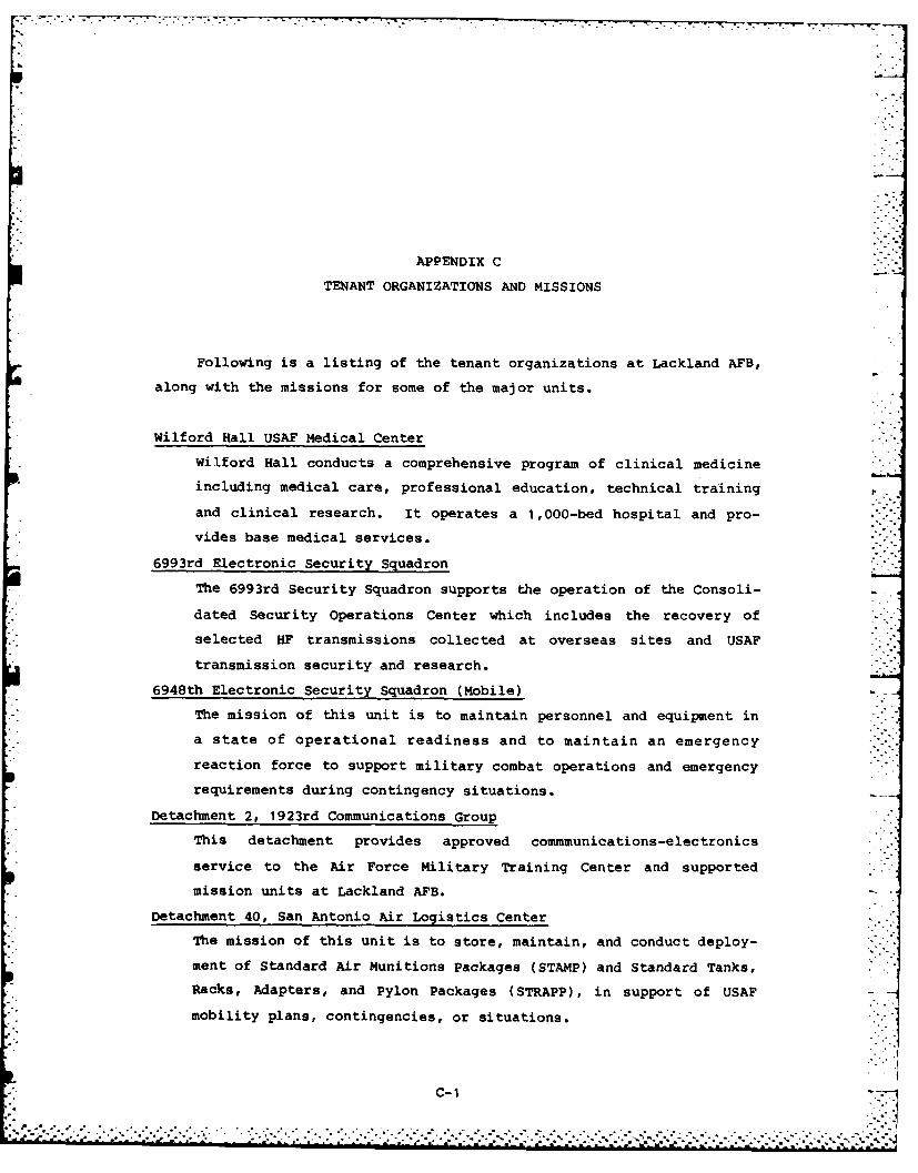
APPENDIX C
TENANT ORGANIZATIONS AND MISSIONS
Following is a listing of the tenant organizations at Lackland AFB,
along with the missions for some of the major units.
Wilford Hall USAF Medical Center
Wilford Hall conducts a comprehensive program of clinical medicine
including medical care, professional education, technical training
and clinical research. It operates a 1,000-bed hospital and pro-
vides base medical services.
6993rd Electronic Security Squadron
The 6993rd Security Squadron supports the operation of the Consoli-
dated Security Operations Center which includes the recovery of
selected HF transmissions collected at overseas sites and USAF
transmission security and research.
6948th Electronic Security Squadron (Mobile) -_
The mission of this unit is to maintain personnel and equipment in
a state of operational readiness and to maintain an emergency
reaction force to support military combat operations and emergency
requirements during contingency situations.
Detachment 2, 1923rd Communications Group
This detachment provides approved commmunications-electronics
service to the Air Force Military Training Center and supported
mission units at Lackland AFB.
Detachment 40, San Antonio Air Logistics Center
The mission of this unit is to store, maintain, and conduct deploy-
ment of Standard Air Munitions Packages (STAMP) and Standard Tanks,
Racks, Adapters, and Pylon Packages (STRAPP), in support of USAF -
mobility plans, contingencies, or situations.
C-1............
::: )!. .
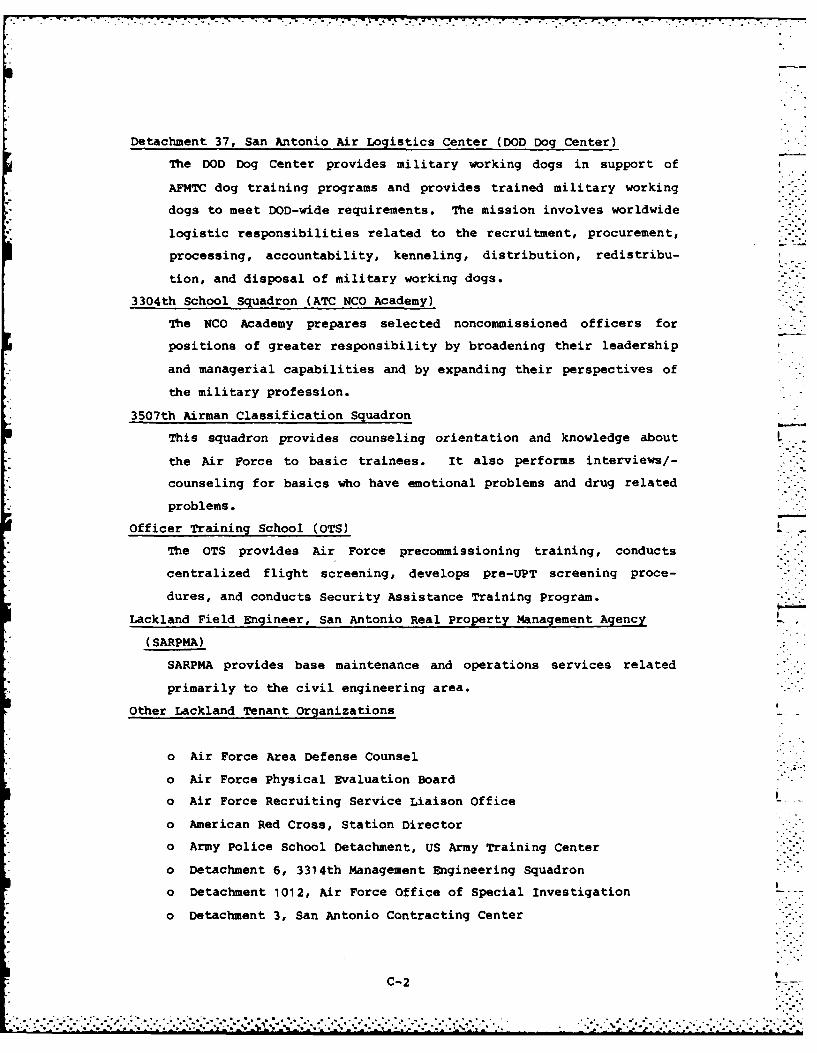
* . .l-n..
Detachment 37, San Antonio Air Logistics Center (DOD Dog Center)
The DOD Dog Center provides military working dogs in support of
AFMTC dog training programs and provides trained military working
dogs to meet DOD-wide requirements. The mission involves worldwide
logistic responsibilities related to the recruitment, procurement,
processing, accountability, kenneling, distribution, redistribu-
tion, and disposal of military working dogs.
3304th School Squadron (ATC NCO Academy)
The NCO Academy prepares selected noncommissioned officers for
positions of greater responsibility by broadening their leadership
and managerial capabilities and by expanding their perspectives of
the military profession.
3507th Airman Classification Squadron
This squadron provides counseling orientation and knowledge about .
the Air Force to basic trainees. It also performs interviews/-
counseling for basics who have emotional problems and drug related
problems.
Officer Training School (OTS)
The OTS provides Air Force precommissioning training, conducts
centralized flight screening, develops pre-UPT screening proce-
dures, and conducts Security Assistance Training Program.
Lackland Field Engineer, San Antonio Real Property Management Agency
(SARPMA)
SARPMA provides base maintenance and operations services related
primarily to the civil engineering area.
Other Lackland Tenant Organizations
o Air Force Area Defense Counsel
o Air Force Physical Evaluation Board
o Air Force Recruiting Service Liaison Office
o American Red Cross, Station Director
o Army Police School Detachment, US Army Training Center
o Detachment 6, 3314th Management Engineering Squadron
o Detachment 1012, Air Force Office of Special Investigation
o Detachment 3, San Antonio Contracting Center
C-2
..... .,° . .. . . .. .%.% . *.'v,. . *. *.. . . . .%.'*..
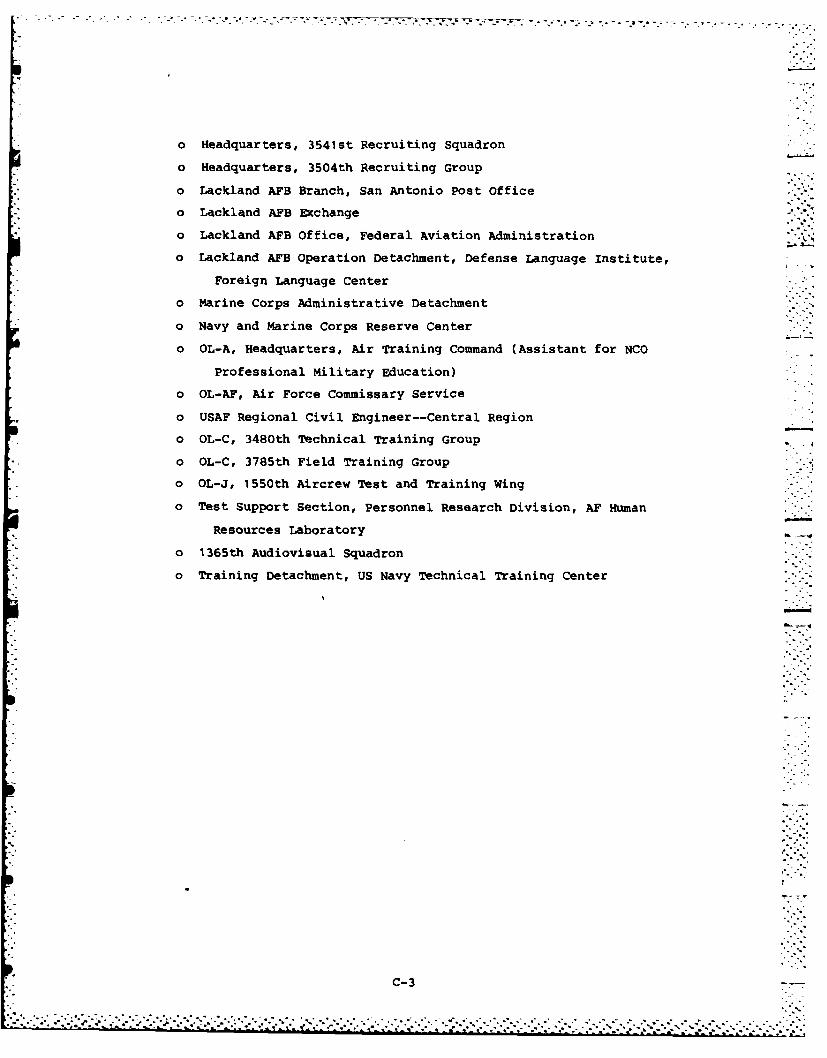
o Headquarters, 3541st Recruiting Squadron
o Headquarters, 3504th Recruiting Group
o Lackland AFB Branch, San Antonio Post Office
o Lackland AFB Exchange
o Lackland AFB Office, Federal Aviation Administration
o Lackland AFB Operation Detachment, Defense Language Institute,
Foreign Language Center
o Marine Corps Administrative Detachment
o Navy and Marine Corps Reserve Center
o OL-A, Headquarters, Air Training Command (Assistant for NCO
Professional Military Education)
o OL-AF, Air Force Commissary Service
o USAF Regional Civil Engineer--Central Region
o OL-C, 3480th Technical Training Group
o OL-C, 3785th Field Training Group
o OL-J, 1550th Aircrew Test and Training Wing
o Test Support Section, Personnel Research Division, AF Human
Resources Laboratory
o 1365th Audiovisual Squadron
o Training Detachment, US Navy Technical Training Center
C- 3
% . .. -
APPENDIX D
SUPPLEMENTAL BASE FINDINGS INFORMATION
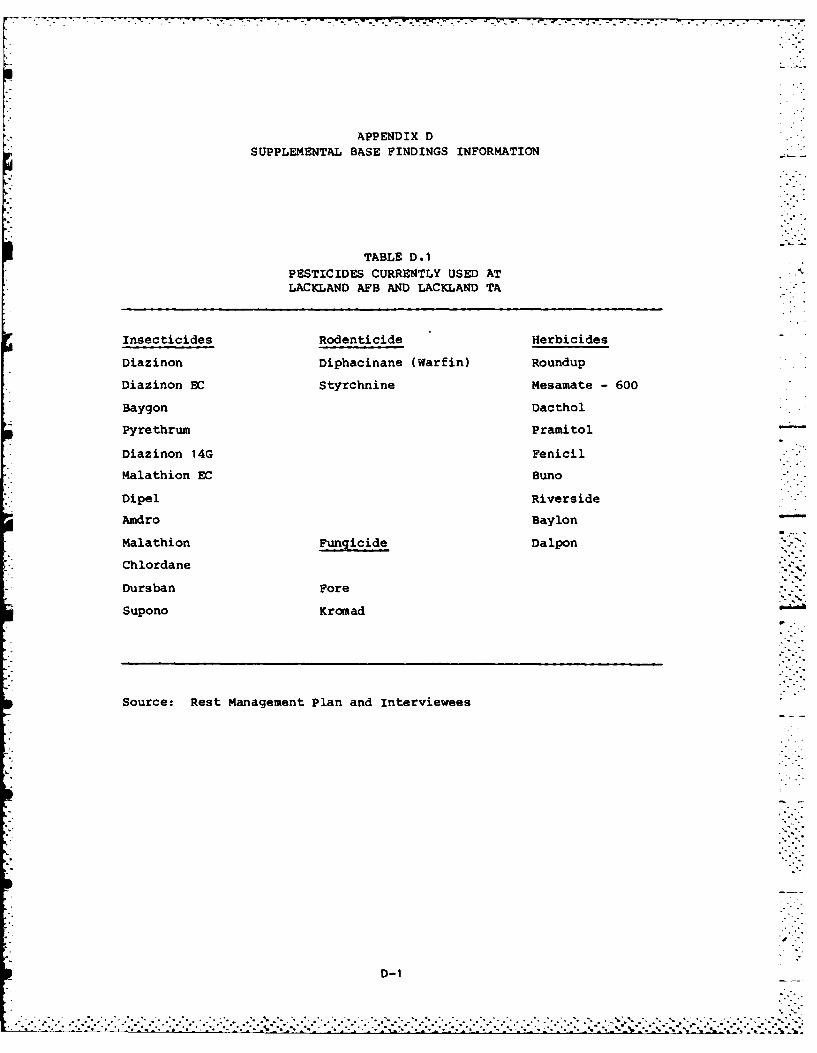
-..
APPENDIX DSUPPLEMENTAL BASE FINDINGS INFORMATION
TABLE DO1PESTICIDES CURRENTLY USED ATLACKLAND AFB AND LACKLAND TA
Insecticides Rodenticide Herbicides
Diazinon Diphacinane (Warfin) Roundup
Diazinon EC Styrchnine Mesamate - 600
Baygon Dacthol
Pyrethrum Pramitol
Diazinon 14G Fenicil-
Malathion EC Buno
Dipel Riverside
Amdro Baylon -
Malathion Fungicide Dalpon
Chlordane
Dursban Fore
Supono Kromad
Source: Rest Management Plan and Interviewees
D-1
. . .. ., °°.. ., . - . • " o ° " . "..- . " . ., ". .. . 0.o . . "o - .. °. . o o. . ° . ° ° ' o . .. ° o ' .* - . - ' , ° . ° ° - . ' . , - '. . . ,:. ~~~- - .- - - - - - - - - - - - - - - - - -.. ,. .. .. .. . . .- ,. - .... -. .. ... . -... .. ... . ,.-... -~-~- -- ... ,. .7.. , ., ..
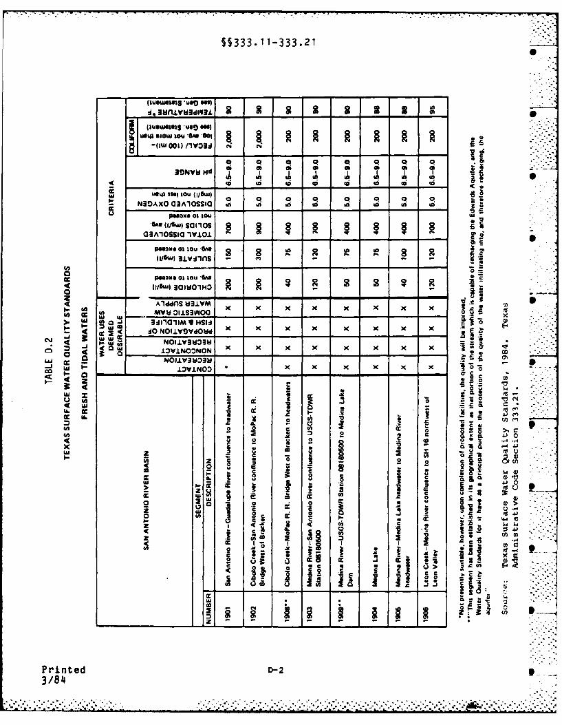
5§333. 11-333.21
:1, 3fl.LV3drV3.L 2 2 2 2 3 3
(I*Wftl 006) on)3j N
-11 00 0 Q 0 0 0
3qNVhlHd o S S S
US U04 SS6 IO I6 liI- - ! -C!- -
- N30AXO 3AIoSa Ag L In to to i i *
UP3210 0) IOU wU
(1/6w)sa,,os 803IiOSSIO l1.LO
P"*- -t ta -L -n to - *o
AiOwl u3vms
> w ~ 3NS 061 IU HSH -
Z ALddCA xV x x x x x x x
w 4c I w - .4 0ol~w
- wS IONWVINONd OD Z X K-4 abo3
co1VN3x w ------------------------------------------ 0i- w NOIW3~c
U. CC
U. J.
(0 0
CL 4 0
43, 0 mq 02tUz 2 z P 'cc - CL C 0
0 a0c- CLE
2~ on A.) n
2 4 (C I; =
z * ,
a J2I I ~ xI
- N > 6______1_C_ z
.c
. ~ ~ ~ ~ ~ ~ U C4C. * * **. . .. . . . . . . . . . . .
. . . . . . .. . . . . . . . . . .
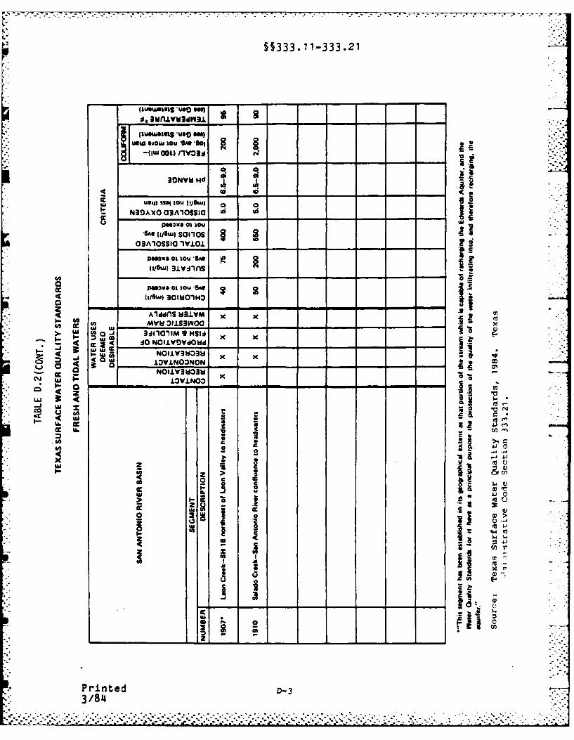
§§333-11-333.21
IU*41 SJOW IOU UAS 'a-(I. 000o /yV3j (4;
9IONV~jNd -
ccU1I4 slag IOU (,j/uG W
S N30AXOaC3AIOSSIaG 0 I
UP"Zxo 01 IOU wjGS(g/Swl Sc~los
03AlOSSIO lV101 L.
C"x I IOU lam
pmW*OIasIOU A"
(1/6w) 3clOWmo~
I-- ~ Wq NoI±v3~ x xo JWY.NOONON c
4z
cc U. fn
0 - -4
x *
3 43EF A
.1
Prne D-33/84
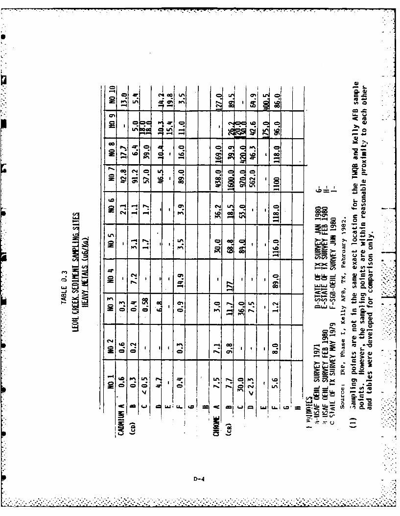
p- S
C1 0 0 LAM0
Q : I I R -
C' -a 0, : 4
o *
*Wo%
LAn
C= -D &A.
W%~> 1-4-4*IO
L0 Q -WL0 4w GR
=~ ~ il 'oF^ cc ,j
I: .-
=ILJ Q
-z LM~
I u -
D-4V-
* .. .. .C.
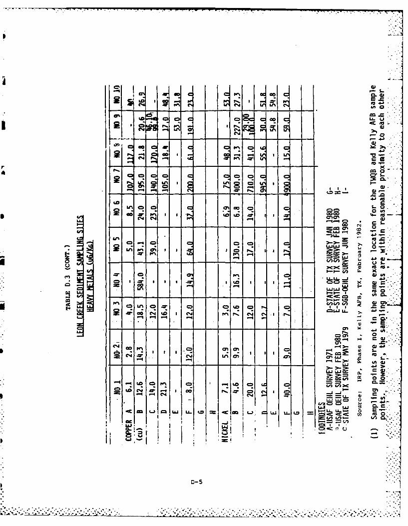
C% I I Ln 4j%
04J
- -
r'z 9 c cm C
N' 0
to t
-ALL 0
aC ~Ci P. , I I -
C.))
CD, L^ --r CD =
AJLL ,
CD cz C4 C,,
00o 4 H W
C"C
c.nc cm 00-5 -4 C C4 Lt; =E
L 4 J U-
uu 0
CI -: ,1: :C;. I
U- 5L E--
L. I *.% .C_ CT
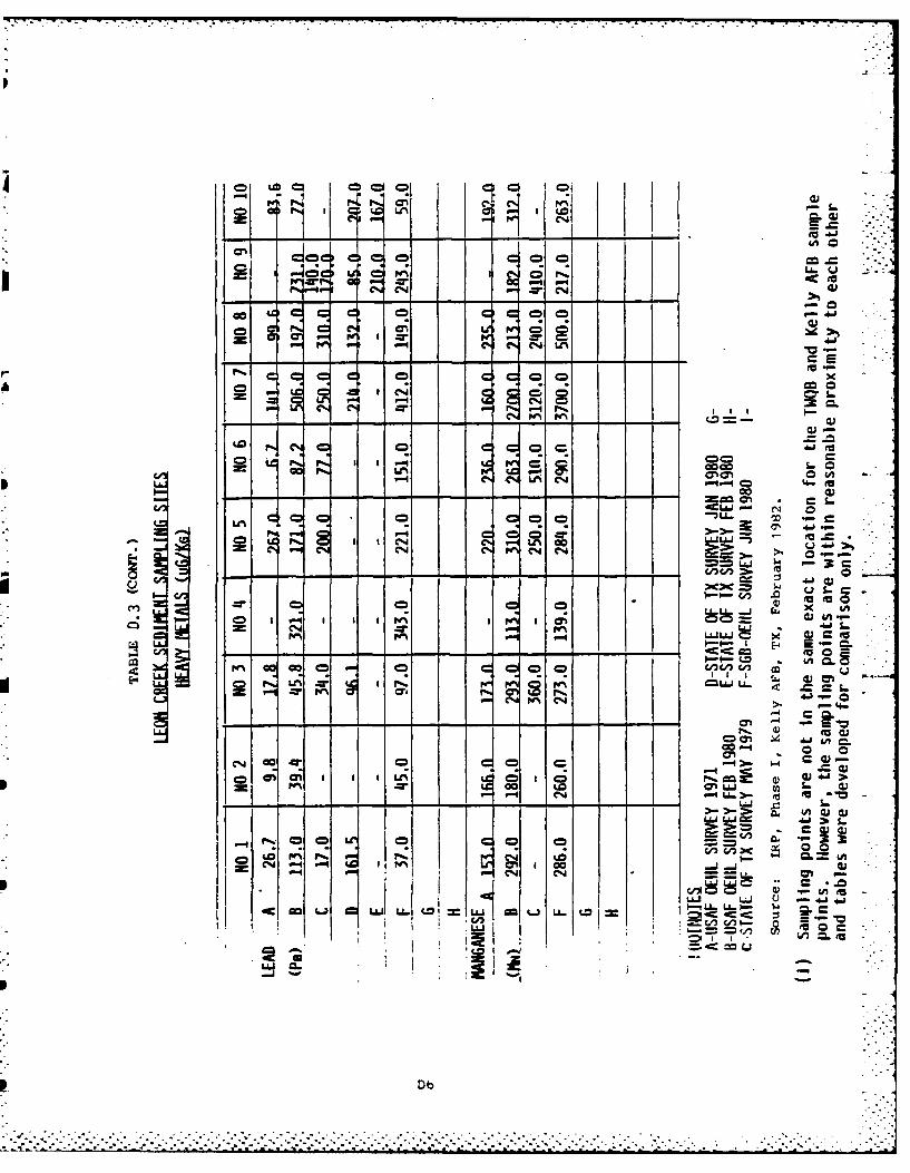
Ip c C =
c~ I l%- a.4
0 .- ~I41
IX g .6j
to
0 N0.4 N 0CLOnP
-2a
cm CR 0- 9 c ocac 1% .-% V-0
-% C"47a.o
0 CN C14 CN L ILJ
00 00n5. 4
E-- -- =---
0c 07 'n CIO Col
E-* 0L I I 0k r^ 8 ^ =.00 S. m - s.. "- C
4w 0 0D
c"'PI I A4
CR = I 0~. .
A4 (A~ fa .
Db
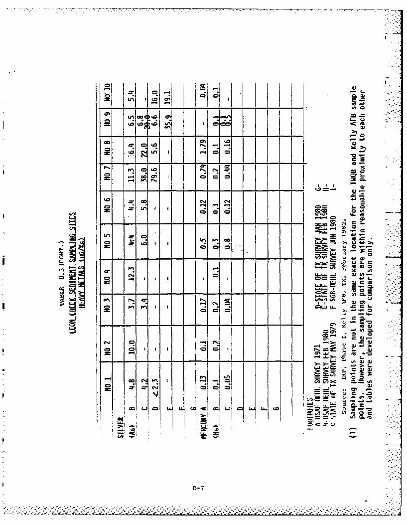
"i~ ~ I Il Ii
u*ic 4 c
** -- 3
-<w 40) uoI-WI
0l- 00
uj =r4N ON :LL O.L I
I0-c~
Ch a) cu
40 w Icl;~~ CD c
j0
Wt CC.*
D-7
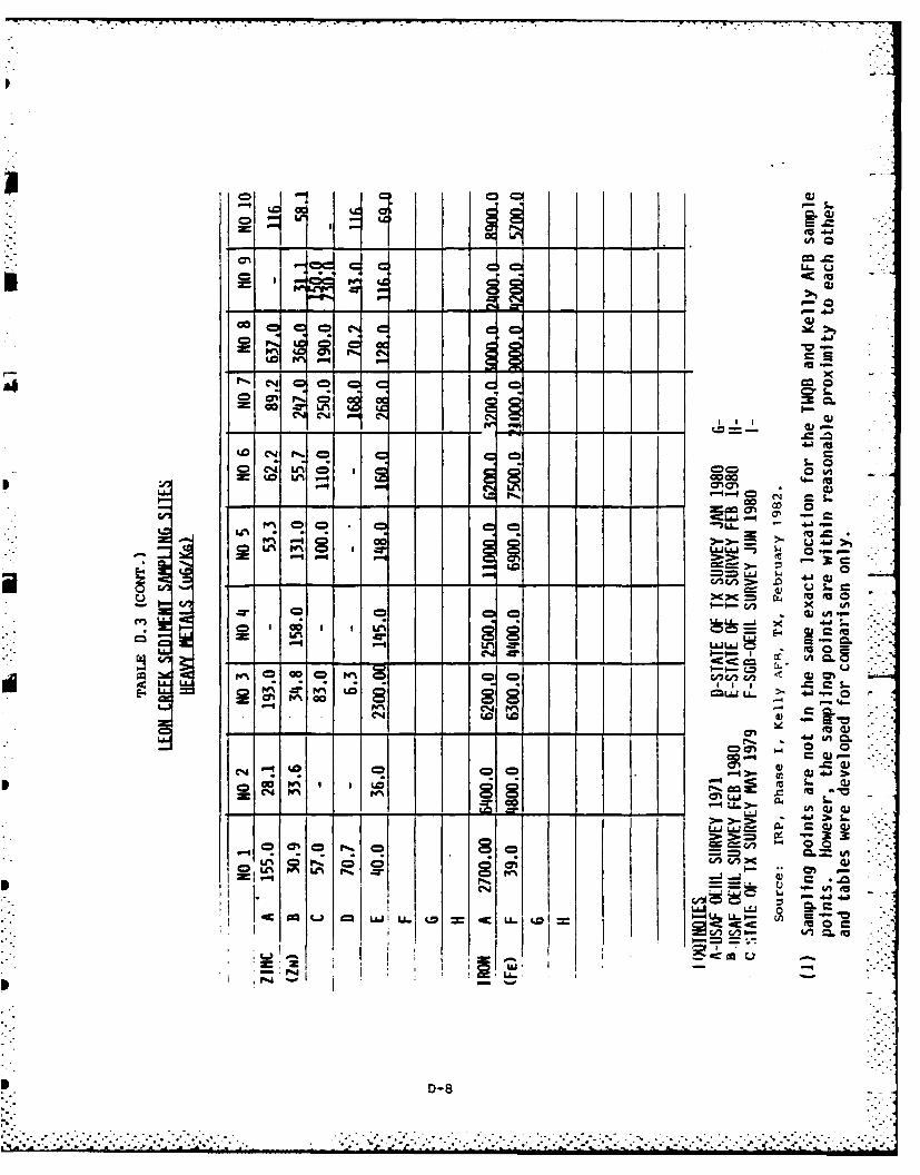
00
CD
o *nmo
to~t
'U.15
IN -T C
a-S
w r^
o I";Ti -., W--I
0!00
IU 0-j u-~ t~ o u- ' 00-
U.I I 4IZ u- .
P D-8
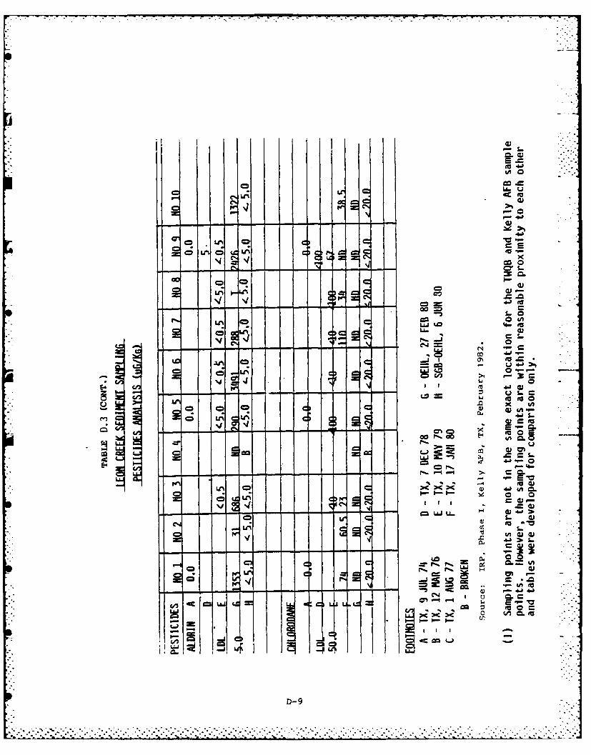
1
LA 4A
L6 0
%4 ab
CID-
to t oo
C4 >4
LA14 m4
*
o r%. LA4c t
- --- -- O'0
S- 1-ULA4 0 cr* -
r%-~ ItJL~
0 I)
0 0
uf I , G
D- 9
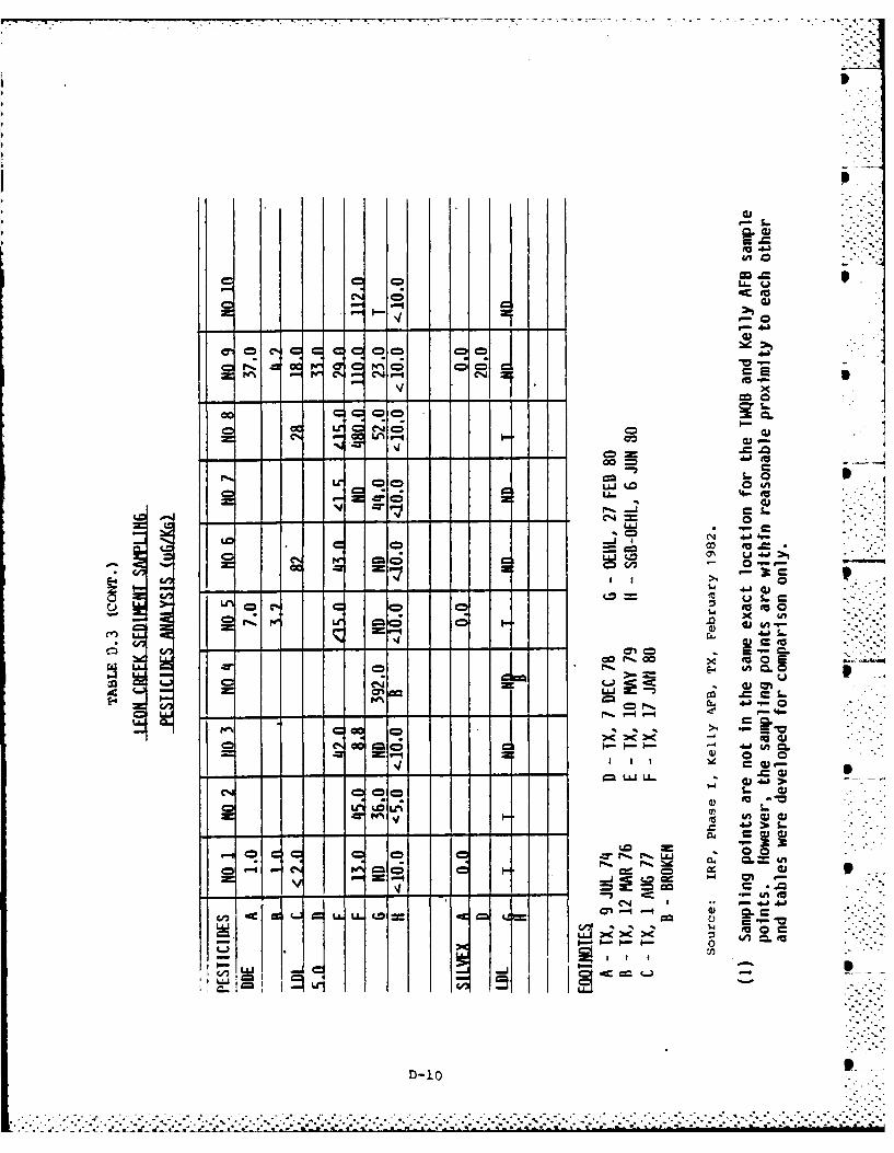
Ii L
C',UCI -n q -o - - -
0V0 -- Cr-.. o
-. j co
'44 .=
00 r.c
LJJ(A
LJd
'ea .10
LiJ R
C44 4.0 4
-') 9 -j L.L . I C"4
- ~ ~ I -0- 0
----------------- -10--------
7.
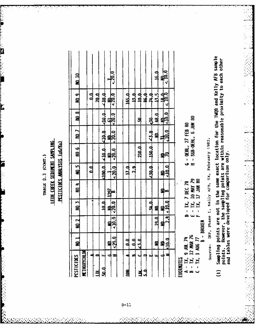
LL.- iv
0- 40
4.b
r'1t
go w0I lCzJ -L -. 34
CN W,
C C,* 0 =0
CNC
V5 L&- c I L A -C~J 4 wLON
u
D-11~
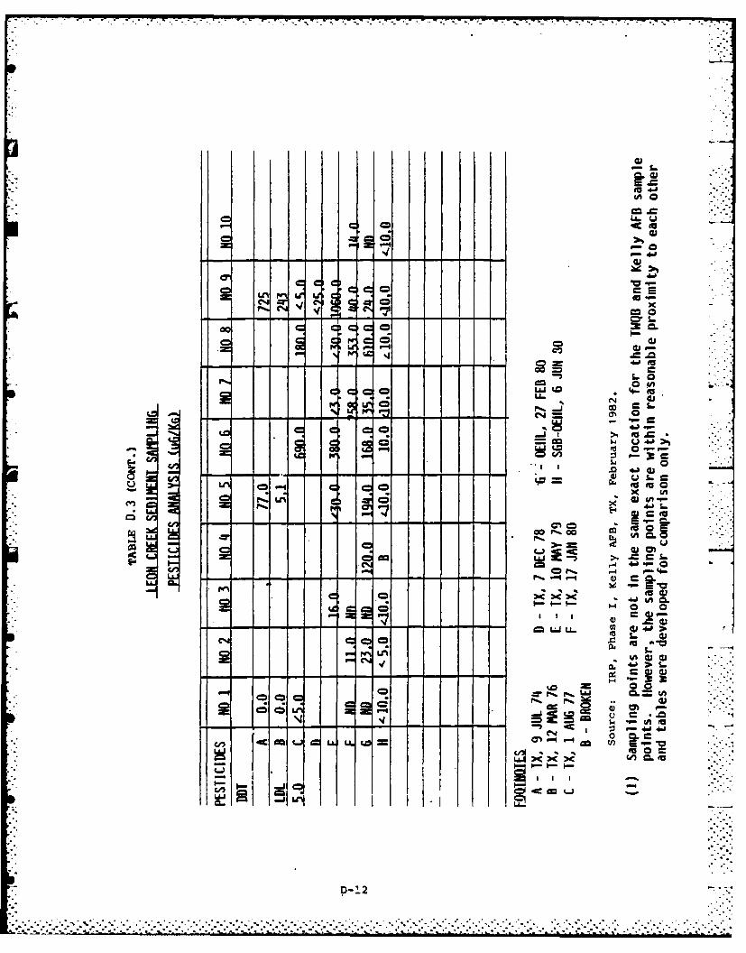
I L
1: 4
CDC
'-4.
PO "-OLt,4 zg C
0mca
ta
1.0
EUU
>.= to
op.. -, 14
(A
ui 'U
S4 cu1(41 1 '
I Cl II =- - S
'.0 c 0cn 4mIU. w t 4'
a -ji :
=D- '2
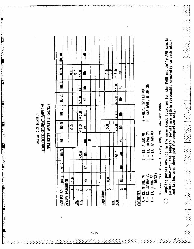
--- 4
EU
'o
Ii. CD
000
LO - 0 =
LM .0 i
co~
- >L,
.V4- P 4
ae 41U7
0LLJS. ( 04
cu (1U)
-4. >N4
-V-,1~~~~1 -J
D- 13
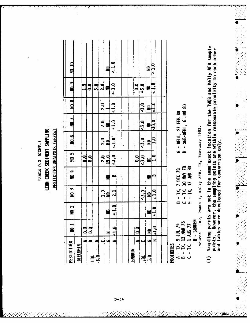
4A
a! L6~
'1 41
al -D - --R
4)
* * 4.
CD 00 C=e
0 C
-G r..=
I-- 41
CR cI w--j *0 >) A
4 ..a :I r@ --. .-...I- Rc
-00 IA 00J 0m 4.1
=C c
D-2-.4- .. b~
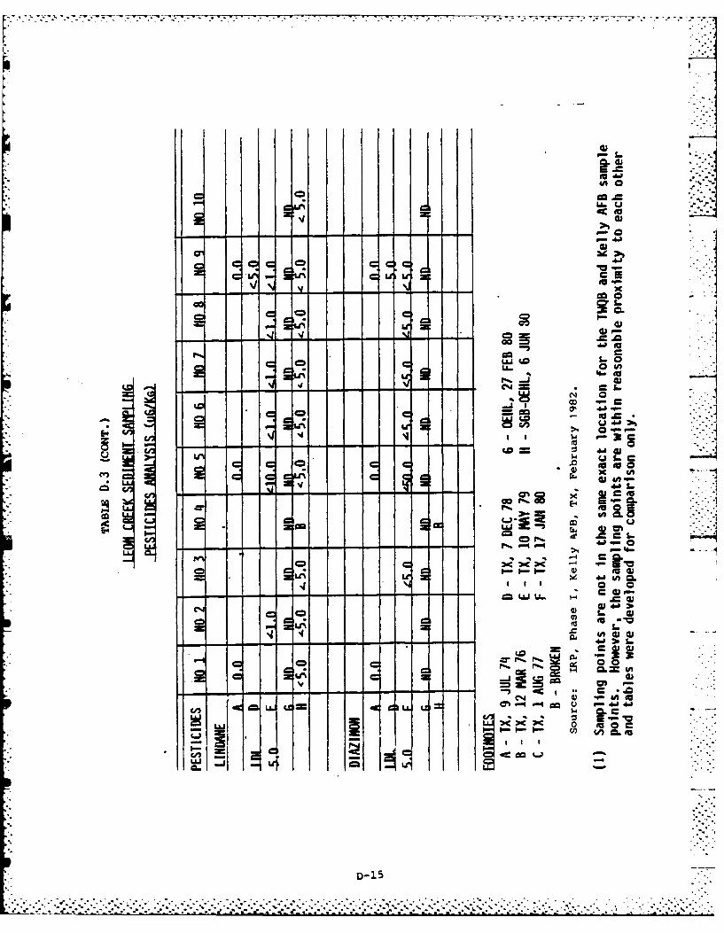
Li-
'140
c C'
fdo 4A J
o coE4- ~g= j o 4'
Ln 1 4*u-'-
11 E~ I I I CA (U 1Rc
V41 :10 S-0 -- - - ~ - - - - - - - - - - a40
Ln C
oC m
LLJ 61'4lOI 9 ~
Z~~i~i~h=~ -15JL i
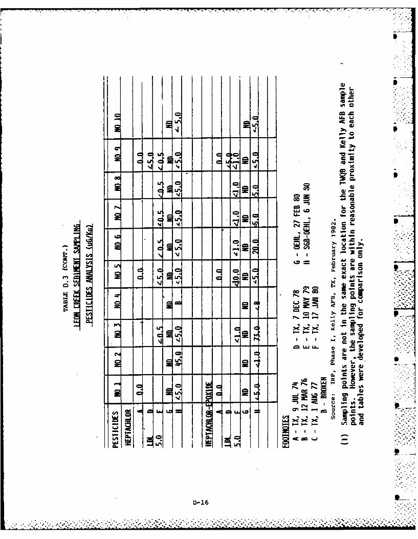
S-
.% 4 to
N - ,- .
go a
oo W 0to
*0 4A-~C -- -- to~_ 4 _ -
oN coLJ 0u
L (IU
M oo go
E4- C 0C
0) cu 4- 2
.CD W S. 0
- - - - -
0A 0 x =~c
p toIc.
.=iCICc, 4.l.1
D- -164.
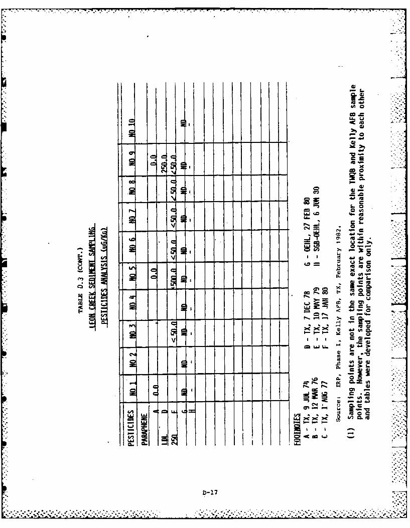
I I f
l Ua,
Iv I4.
. = I..
CA -0 -&
u - - - -'*f
uiI
aj
'-24Iw
z:: :74
' a
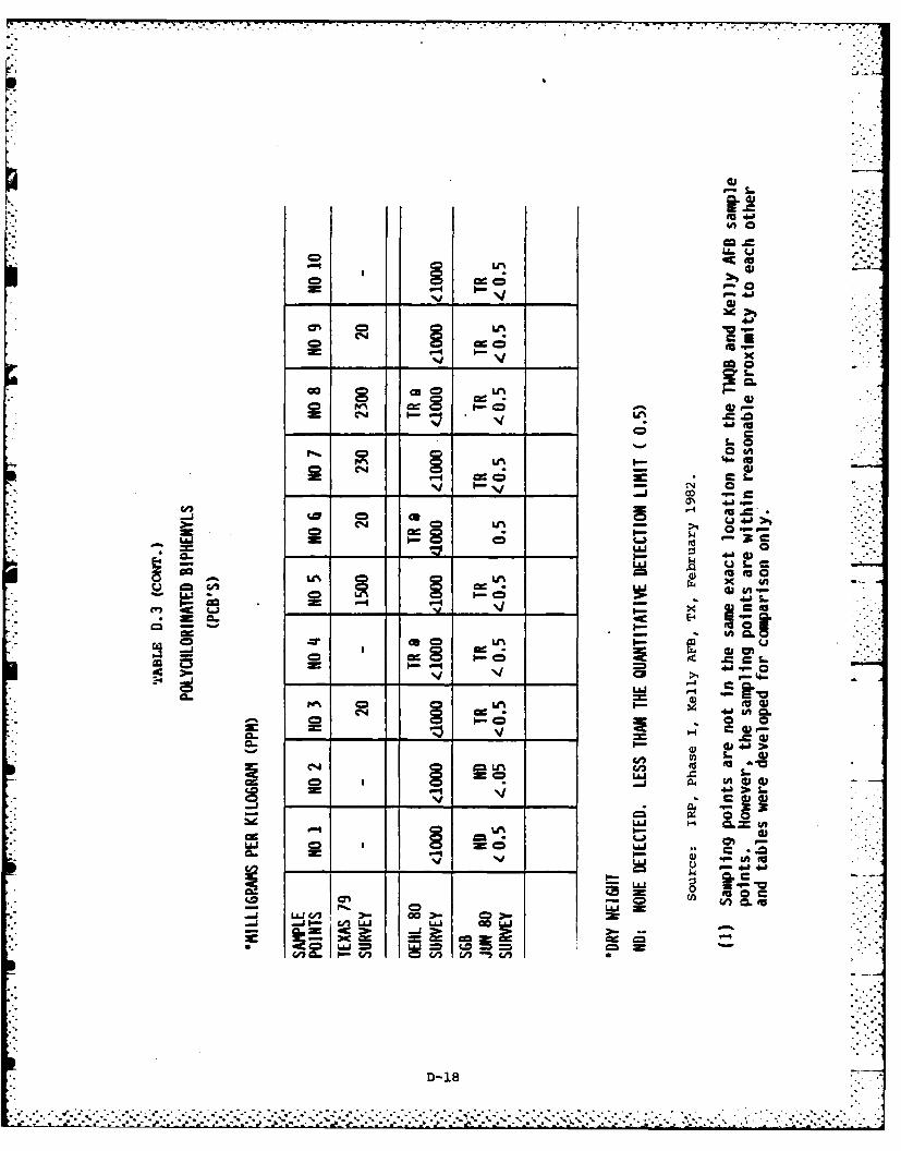
.,. . . . .
F-"
[.4'
Gno
C7 '4o
C) -°-
a~ 0
Go-- ce ) fI-
--,I- C-.=;
a, .a.
40
= CJi4 I-v .- L..
04 40
*_o o 0
|0- ---
-8 3--C
.,. 4Jq
.44
PC 0- 4-J S.qa
=o Lu g
Lu- - ~ I. c;i
C4 xl
c cu
C cu.
0. cu
CA 4
-0 'a 0
cn~~~ CL. P. @11 '
.~~L .~ .. . . . .
APPENDIX E
MASTER LIST OF SHOPS
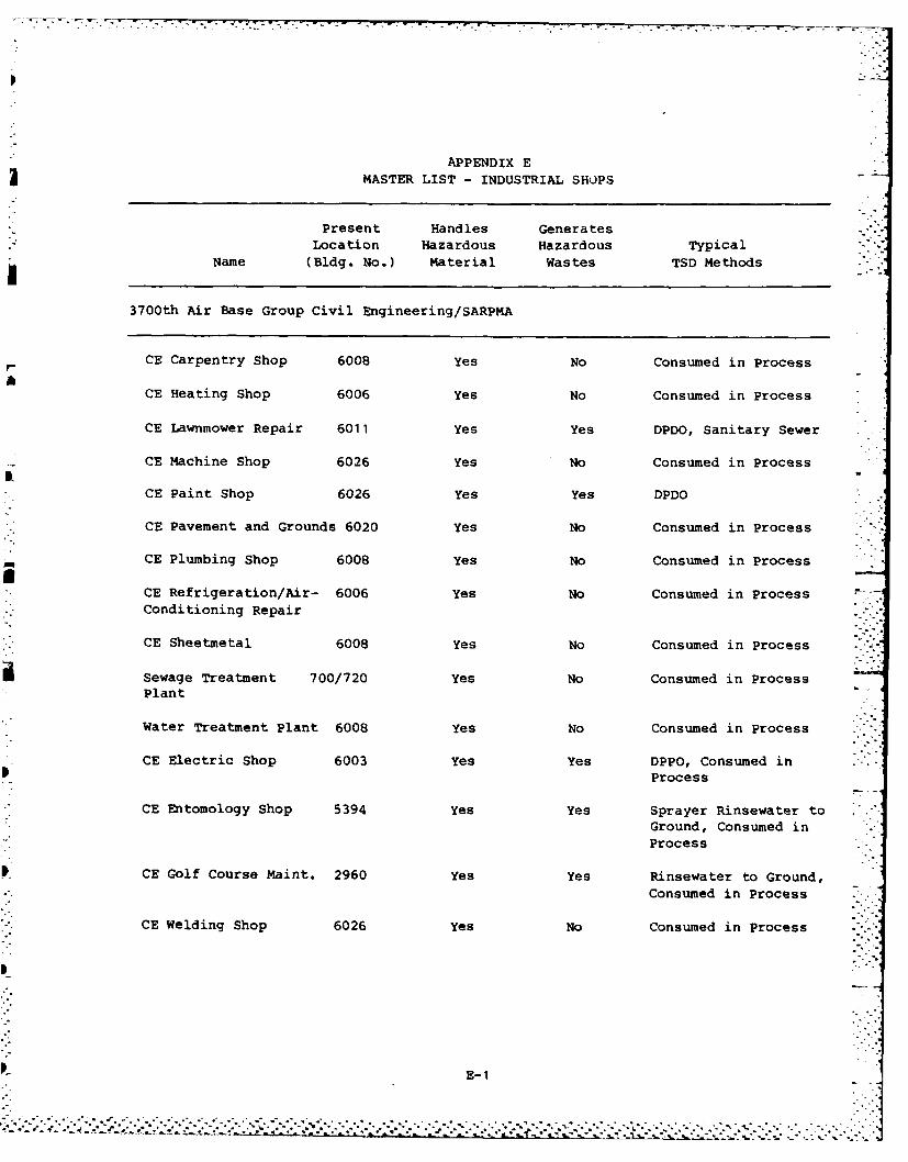
APPENDIX E
MASTER LIST - INDUSTRIAL SHOPS
Present Handles GeneratesLocation Hazardous Hazardous Typical
Name (Bldg. No.) Material Wastes TSD Methods
3700th Air Base Group Civil Engineering/SARPMA
CE Carpentry Shop 6008 Yes No Consumed in Process
CE Heating Shop 6006 Yes No Consumed in Process
CE Lawnmower Repair 6011 Yes Yes DPDO, Sanitary Sewer
CE Machine Shop 6026 Yes No Consumed in Process
CE Paint Shop 6026 Yes Yes DPDO
CE Pavement and Grounds 6020 Yes No Consumed in Process
CE Plumbing Shop 6008 Yes No Consumed in Process
CE Refrigeration/Air- 6006 Yes No Consumed in ProcessConditioning Repair
CE Sheetmetal 6008 Yes No Consumed in Process
Sewage Treatment 700/720 Yes No Consumed in ProcessPlant
Water Treatment Plant 6008 Yes No Consumed in Process
CE Electric Shop 6003 Yes Yes DPPO, Consumed inProcess
CE Entomology Shop 5394 Yes Yes Sprayer Rinsewater toGround, Consumed inProcess
CE Golf Course Maint. 2960 Yes Yes Rinsewater to Ground,Consumed in Process
CE Welding Shop 6026 Yes No Consumed in Process .'- -
E-1
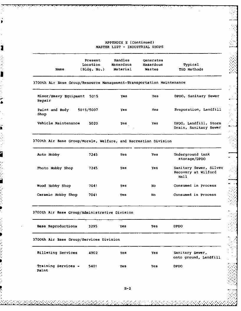
APPENDIX E (Continued)MASTER LIST - INDUSTRIAL SHOPS
Present Handles GeneratesLocation Hazardous Hazardous Typical
Name (Bldg. No.) Material Wastes TSD Methods
3700th Air Base Group/Resource Management-Transportation Maintenance
Minor/Heavy Equipment 5015 Yes Yes DPDO, sanitary Sewerr Repair
Paint and Body 5015/5007 Yes Yes Evaporation, LandfillShop
Vehicle Maintenance 5020 Yes Yes DPDO, Landfill, Storm
Drain, Sanitary Sewer
3700th Air Base Group/Morale, Welfare, and Recreation Division
Auto Hobby 7245 Yes Yes Underground tankstorage/DPDO
Photo Hobby Shop 7245 Yes Yes Sanitary Sewer, SilverRecovery at Wilford
Hall
Wood Hobby Shop 7041 Yes No Consumed in Process
Ceramic Hobby Shop 7041 Yes No Consumed in Process
3700th Air Base Group/Administrative Division
Base Reproductions 3295 Yes Yes DPDO
3700th Air Base Group/Services Division
Billeting Services 4902 Yes Yes Sanitary Sewer,
onto ground, Landfill
Training Services - 5401 Yes Yes DPDOPaint
P E- 2
...............................................
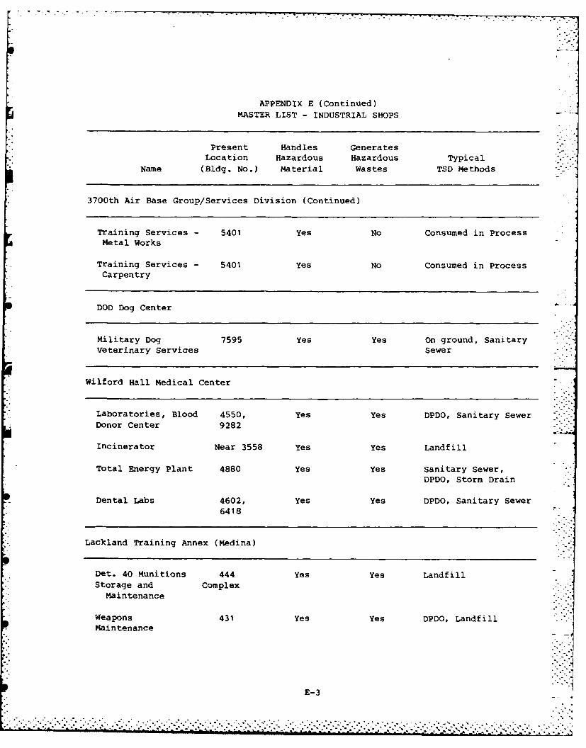
APPENDIX E (Continued)MASTER LIST - INDUSTRIAL SHOPS
Present Handles GeneratesLocation Hazardous Hazardous Typical
Name (Bldg. No.) Material Wastes TSD Methods
3700th Air Base Group/Services Division (Continued)
Training Services - 5401 Yes No Consumed in ProcessMetal Works
Training Services - 5401 Yes No Consumed in ProcessCarpentry
DOD Dog Center
Military Dog 7595 Yes Yes On ground, SanitaryVeterinary Services Sewer
Wilford Hall Medical Center
Laboratories, Blood 4550, Yes Yes DPDO, Sanitary Sewer
Donor Center 9282
Incinerator Near 3558 Yes Yes Landfill
Total Energy Plant 4880 Yes Yes Sanitary Sewer,DPDO, Storm Drain
Dental Labs 4602, Yes Yes DPDO, Sanitary Sewer6418
Lackland Training Annex (Medina)
Det. 40 Munitions 444 Yes Yes LandfillStorage and Complex
Maintenance
Weapons 431 Yes Yes DPDO, LandfillMaintenance
E-3
" . . ..
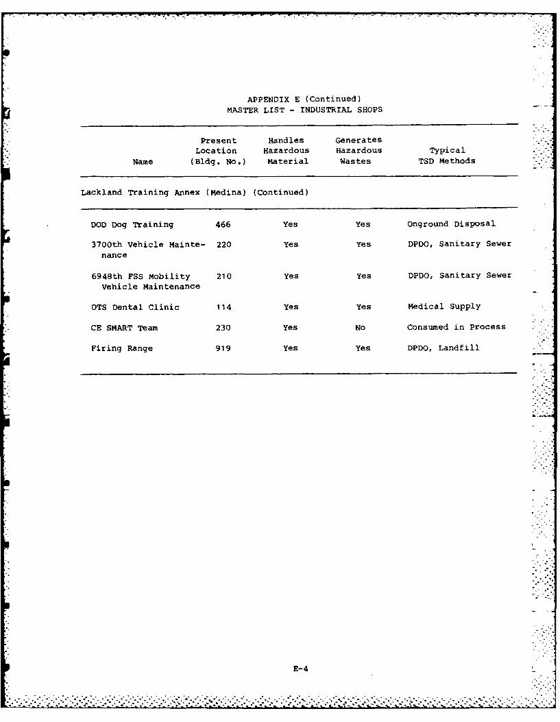
APPENDIX E (Continued)MASTER LIST - INDUSTRIAL SHOPS
Present Handles Generates
Location Hazardous Hazardous Typical
Name (Bldg. No.) Material Wastes TSD Methods
Lackland Training Annex (Medina) (Continued)
DOD Dog Training 466 Yes Yes Onground Disposal
3700th Vehicle Mainte- 220 Yes Yes DPDO, Sanitary Sewer
nance
6948th FSS Mobility 210 Yes Yes DPDO, Sanitary Sewer
Vehicle Maintenance
OTS Dental Clinic 114 Yes Yes Medical Supply
CE SMART Team 230 Yes No Consumed in Process
Firing Range 919 Yes Yes DPDO, Landfill - -
E--4
.................................................. - .........- ~.-.-. .......... ..... ~ -- .-- ---
APPENDIX F
PHOTOGRAPHS

-- i z -4E
F-I
* ...... .. *. ..-. .-*~** * .. *. . . . . . . . . . . . . . . . .. *.. ..- 26
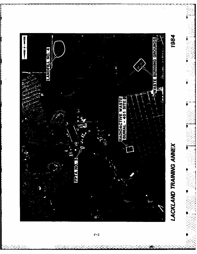
Aft
'61
t s ,
top
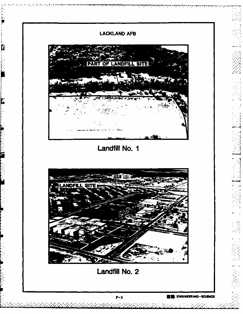
LACKLAND AFB
Landfill No. 2
LADFL SITEIE~nGSI~c
-4,*'.*- ='-**~,*
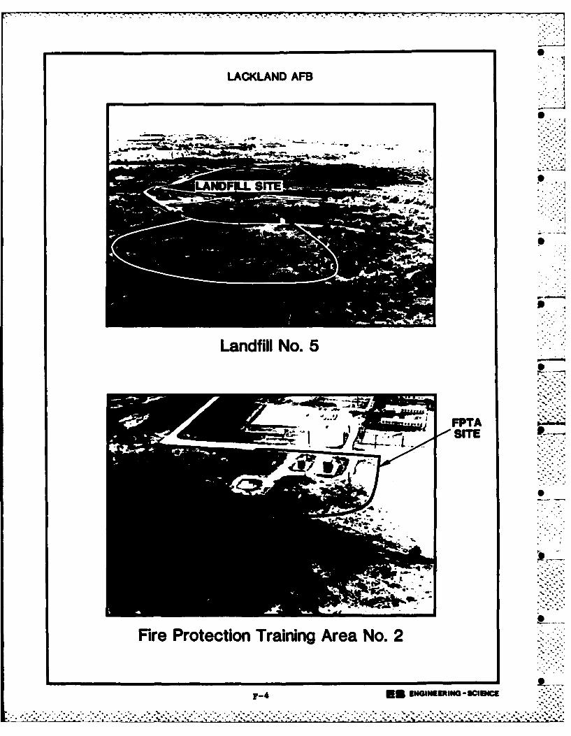
LACKLAND AFB
SITE
At-l
F-4-
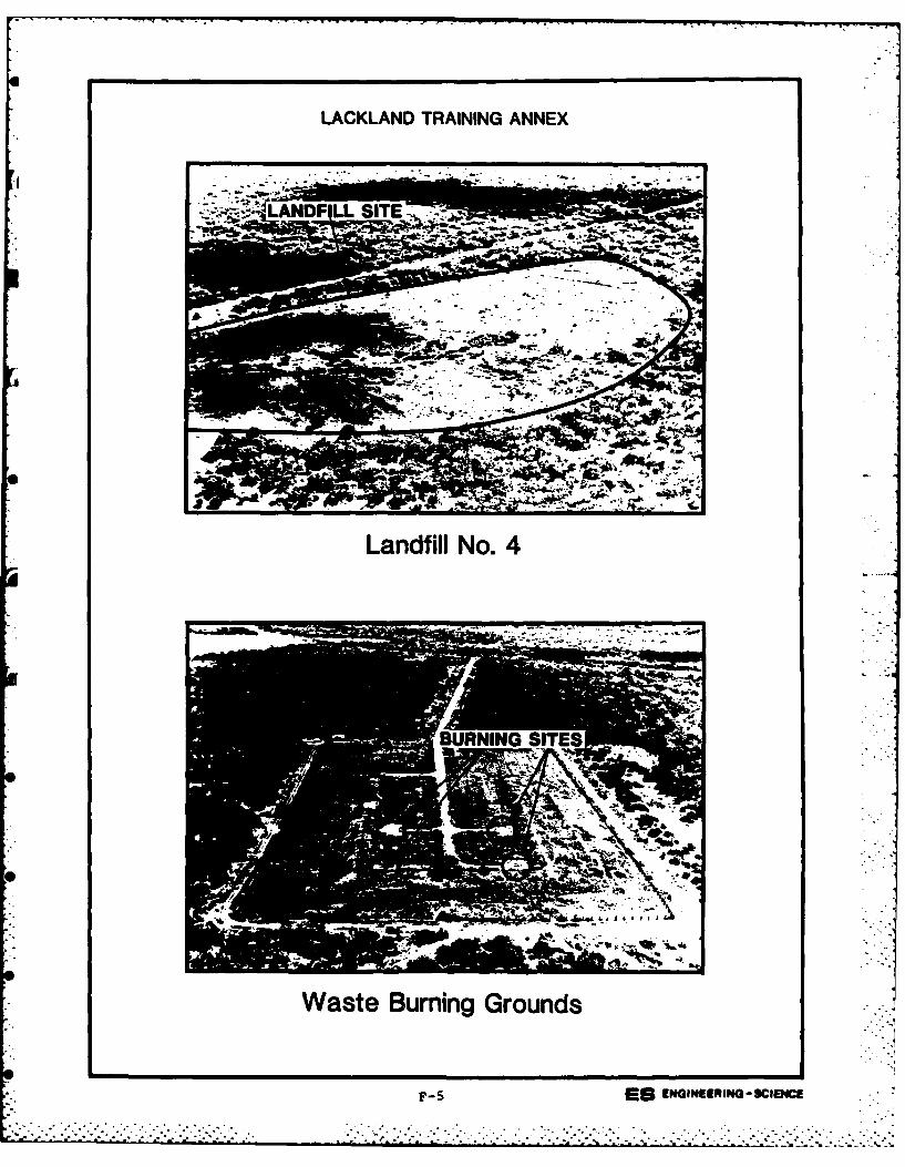
LACKLAND TRAINING ANNEX
Landfill No. 4
Waste Burning Grounds
F-S5m ENGINEERING -SCIEM
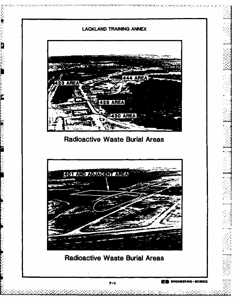
R,. - --- r-,-r------,---------w------------ rrw ~ - ---
LACKLAND TRAINING ANNEX
Radioactive Waste Burial Areas
401 A
Radioactive Waste Burial Areas
7-6 EU ENGINEERING -SCIEMCM~ . . . . .'. .. . *. . ....-. .
APPENDIX G
USAF INSTALLATION RESTORATION PROGRAM HAZARD
ASSESSMENT RATING METHODOLOGY
-S%
.. .. . . . . . . . . . . . . . -. .
APPENDIX G
USAF INSTALLATION RESTORATION PROGRAM
HAZARD ASSESSMENT RATING METHODOLOGY
BACKGROUND
The Department of Defense (DOD) has established a comprehensive
program to identify, evaluate, and control problems associated with past
disposal practices at DOD facilities. One of the actions required under
this program is to:
"develop and maintain a priority listing of con-taminated installations and facilities for remedialaction based on potential hazard to public health,welfare, and environmental impacts." (Reference:DEQPPM 81-5, 11 December 1981).
Accordingly, the United States Air Force (USAF) has sought to establish
a system to set priorities for taking further actions at sites based
upon information gathered during the Records Search phase of its In-
stallation Restoration Program (IRP).
The first site rating model was developed in June 1981 at a meeting
with represenatives from USAF Occupational and Environmental Health
Laboratory (OEHL), Air Force Engineering and Services Center (AFESC),
Engineering-Science (ES) and CH2M Hill. The basis for this model was a
system developed for EPA by JRB Associates of McLean, Virginia. The JRB
model was modified to meet Air Force needs.
After using this model for 6 months at over 20 Air Force installa-
tions, certain inadequacies became apparent. Therefore, on January 26
and 27, 1982, representatives of USAF OEHL, AFESC, various major com-
mands, Engineering-Science, and CH2M Hill met to address the inade-
quacies. The result of the meeting was a new site rating model designed
tc present a better picture of the hazards posed by sites at Air Force
installations. The new rating model described in this presentation is
referred to as the Hazard Assessment Rating Methodology.
G-1." . . . .* . o . * . . . . . .. . . .•"...:...... . - " .. ." ..*.'."... ...- / ,. '..,.', ,'...*..,.-*..t'','v . "'t'.''..- , .'' .,-'',' .,." '.....".,... .
PURPOSE
The purpose of the site rating model is to provide a relative
ranking of sites of suspected contamination from hazardous substances.
This model will assist the Air Force in setting priorities for follow-on
site investigations and confirmation work under Phase II of the IRP.
This rating system is used only after it has been determined that
(1) potential for contamination exists (hazardous wastes present in
sufficient quantity), and (2) potential for migration exists. A site
can be deleted from consideration for rating on either basis.
DESCRIPTION OF MODEL
Like the other hazardous waste site ranking models, the U.S. Air
Force's site rating model uses a scoring system to rank sites for
priority attention. However, in developing this model, the designers
incorporated some special features to meet specific DOD program needs.
The model uses data readily obtained during the Records Search
portion (Phase I) of the IRP. Scoring judgments and computations are
easily made. In assessing the hazards at a given site, the model
develops a score based on the most likely routes of contamination and """
the worst hazards at the site. Sites are given low scores only if there
are clearly no hazards at the site. This approach meshes well with the
policy for evaluating and setting restrictions on excess DOD properties.
As with the previous model, this model considers four aspects of
the hazard posed by a specific site: the possible receptors of the
contamination, the waste and its characteristics, potential pathways for
waste contaminant migration, and any efforts to contain the contami-nants. Each of these categories contains a number of rating factors
that are used in the overall hazard rating.
The receptors category rating is calculated by scoring each factor,
multiplying by a factor weighting constant and adding the weighted
scores to obtain a total category score.
G-2. . * * °. * .- ' . ° °° .' .O * -* ° . ° .* -* . . . . . . . . ...'. % °.o••" °°• ° - ° o . . .. °.°°o° . . .
"_,~o ' .. 2 . _,-.. °- _'. ' ,"
,.. . . . =*.':,", _ -.'-'. .' . '_,' ,.' ,- ,°'.
". '' . """" . .-. " "." -" "" . " . ". " " "* * . " °.' , - . - .- ...-. -'
The pathways category rating is based on evidence of contaminant
migration or an evaluation of the highest potential (worst case) for
contaminant migration along one of three pathways. If evidence of
contaminant migration exists, the category is given a subscore of 80 to
100 points. For indirect evidence, 80 points are assigned and for
direct evidence, 100 points are assigned. If no evidence is found, the
highest score among three possible routes is used. These routes are
surface water migration, flooding, and ground-water migration. Evalua-
tion of each route involves factors associated with the particular mi-
gration route. The three pathways are evaluated and the highest score
among all four of the potential scores is used.
The waste characteristics category is scored in three steps.
First, a point rating is assigned based on an assessment of the waste
quantity and the hazard (worst case) associated with the site. The
level of confidence in the information is also factored into the
assessment. Next, the score is multiplied by a waste persistencefactor, which acts to reduce the score if the waste is not very
persistent. Finally, the score is further modified by the physical
state of the waste. Liquid wastes receive the maximum score, while
scores for sludges and solids are reduced.
The scores for each of the three categories are then added together
and normalized to a maximum possible score of 100. Then the waste man-
agement practice category is scored. Sites at which there is no con-
tainment are not reduced in score. Scores for sites with limited con-
tainment can be reduced by 5 percent. If a site is contained and well --
managed, its score can be reduced by 90 percent. The final site score
is calculated by applying the waste management practices category factor
to the sum of the scores for the other three categories.
G-3"" . . G - .-. -.,
.. .................. .o , _
"" """" """" """-: -" "" " """" "' ""' "" " "-" "'" ""' """-" " "'" " "" " "" " "-".. . . . . . . . . .. . . . . . . . .".. .. ,. ."-.."".. . .... ."... .-. ... ""-.'.. .,
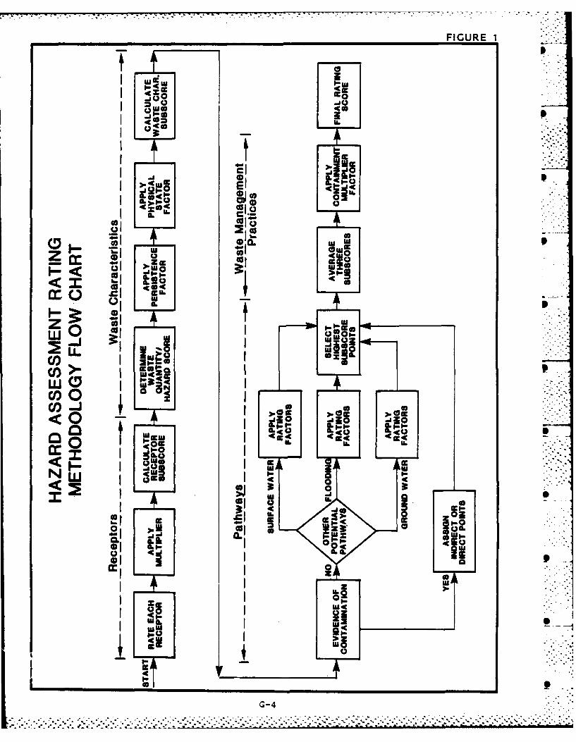
FIGURE 1
I Ito
ca
I - CD a.co 0.
us oI
C') 0 Iwo
I-)> 4Ic
coOco-n
Ic 4io co
LT IoL ,.W I-Wz' 0
cc -0
Ia I N
ol L -1.
010
4r
4G-
................... ~...-...T.....*~ ~A ~ - - -------G-4
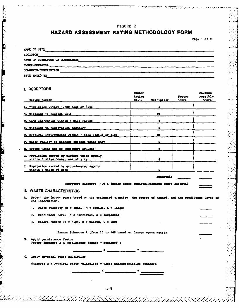
FIGURE 2
HAZARD ASSESSMENT RATING METHODOLOGY FORMPage lof 2
coamon/0933CZIfl
L RECEPTORSFactor m~axism-lasIiW Factor Possible
R.at ng ?actcJ (0-3) .4ult vliet Score Score
A. ouvulation within 1.000 feet of 'site I4
3. oittance to nearest well 1 10
C. Land use/zonin. within I mile radius 3
0. oi stance to reservation boundary S __
9. Crit*.Cal .awtrowents within I ile radius ale site -10
* 7. Water ouaLlt' of nearest surf ace water body 1 _____ _____
. ,round ,ater use of ,M. smeot aquifr 9"__.
3. Population served by surface voater sewly
within 3 miles onsa of site -41. Population served by ground-wate spy .,Withir.+n 3 miles at $its= 4 "
SubotaLs
Receptors subscore (100 X factor scare subota.l/maxims saore subtotal)
IL WASTE CHARACTERISTICS
A. Sel.c the factor ore based on the estimated qunwtity, th.e degree of hazard, and t e confidence leve. atthe information.
. fase quantity (S a small, .. a medium., L a Large)
2. Confidence leve. (C , confirmed, S - suspected)
3. aacd rating (3 h bigh, Xt medium, L l low)
Factor Subsoore A (from 20 to 100 based on factor score matrix)
* 3. Aply persistence factorFactor Subsore A X Plerslstenc Facor * Subscoge a
__ _ _ _x ____ ___
C. AWPLY physical, state mul:iplier
Suscoe 3 X 7Pl-. ical State , ."ltiplist * waste C"a.acterist-cs Sub-'ace
G- 5
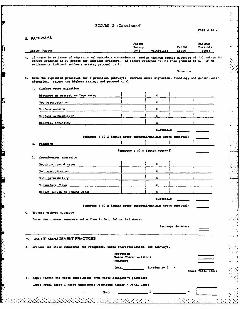
FIGURE 2 (Continued)Page 2 of 2
IUL PATHWAYSFactor Maximum
Rating Factor PossibleRating Factor (0-3) Multioiise Score Score
A. If there is evidence of migration of hazardous contaminants, assign muaximum factor subscoce of 100 pounts t:direct evidence or 80 points for indirect evidence. If direct evidence exists th1en proceed to C. I! noevidence or indirect evidence exists, proceed to B.
Subecore
a. Rate the migration potential faot 3 potential pathwvyst surface water migration, flooding, and ground-watermigration. Select the highest rating, aid proceed to C.
1. Surface water migration
Oistance to nearest surface water _ J.et precipitation _ 6
Surface erosion a
Surface marmeability_______ 6 _____________
RainfalL intensity [______ ____________
Subtoatals
Subacore (100 X factor score subtotal/maximu score subtotal)
* 2. ?loodira
Subscoce (100 x factor score/3)
3. Ground-water migration
Depth to ground water _ , __-
let oreciitation ._ _ 6_ _ _ _ _ _ _ _ _ _ _ _ _ _ _ I _ _ _ _ _ _ I _ _ _ _ _Soil oemeabil_ _-___ 3 _ _,._ _
Suosurface flows _ __ _ '
Direct access to ground water J ______j 3 ____________
Subtotals
Sub core (100 x factoc scots subtotal/maximum score subtotal)
C. Highest shway subscoce.
Enter the -aghest su core value from A, 3-1, 5-2 or 3-3 above.
Pathways Subscte
IV. WASTE MANAGEMENT PRACTICES
A. Average -,e three subsaos for receptors, waste characteristics, and pathways.
ReceptocsWaste CharacteristicsPathways
Total_ _ divided zy 3 *..._,
Gross tOtal Score
3. Apply factor for waste containment from waste management practices
Gross Total Scote X asts Manaqement Practices ?Fctor ?inal Score
G-6, X______ __'_'___.................................. ...- . .. .
.. ' -..-. - .: . .' -i. - '-' . L ' .*': " ]-.' .- ' - .. " . *. . -'.. ' -. .. . .. , '." - ,". -. .• " . ": "-.
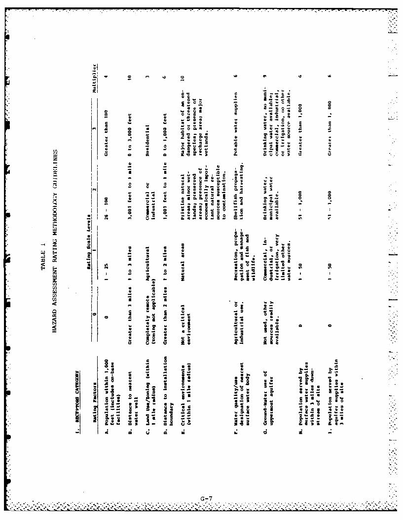
:311
a . ~ o a
a a.. es
w ~ V. -4
a a ; to- w w
M, 4-.
c* aa M - ~ a -- ~= a a
a a a aa as-au
'- aC aCca
- ~~~ - aa:0 a
0 24 X4 JU 2 a
-- a. -~a -
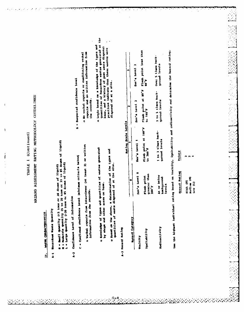
.wZ
2kD.4 4 ob0 m C
C w 4a 4F: ~ AAHq
Hem Vg
*~ 4 * 4
44H4La 0
41 %
As -
04-. 4
.j.
z H
40 2 1 03 40
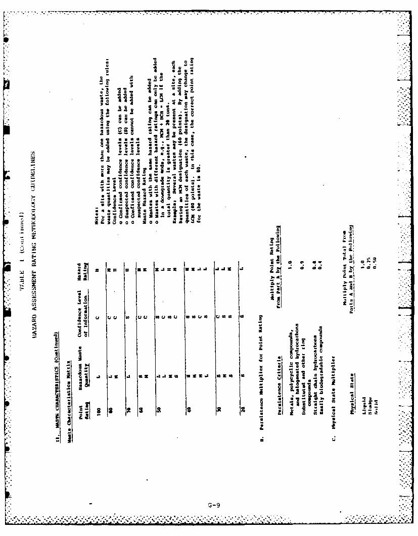
41 f, a ~ a
2 00
2 a, : 0
4 1
S -a to "a -O
1;0 z
41 -H U
cn~
U a U6 (A u U r ou G cww c m(
3-. to HzO .4 AHO~ Z a 3 9 u a f
-- t
-,-,
-3G39
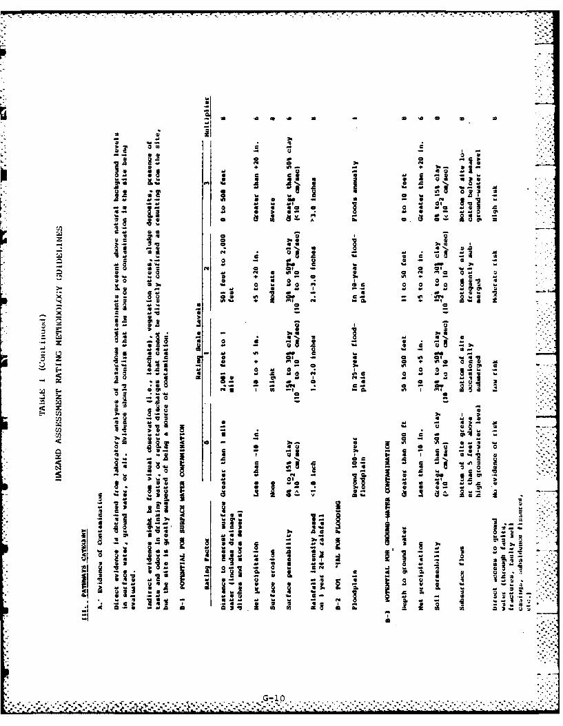
41 44
-' 'A 31'
4.1 go 5
on 0 of 10 M
-- 2.0 41 M. 3 -
- 41*
a. %d e I - 2 a
E. 41C &I1 1
3-~~G 14,a 11
ac a 0 04 -4mO a~3 - 3K : aN 13-4 a ' d
0~r 3M 41 a 1
49 Mw "da
a1 0
a~ -41 4d a C a~4 1
41 -0 ma
0- -a. I m!- 7Z Z1 --4 a*
-d A4a 0-= z. 3
41~ 41 ~ M4f7
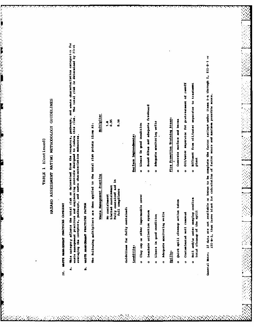
2-
10
-4 w
20
4w~41
4M
1 2
r. .81
hi 3 hi
- -. 4* ag
'-I o~j 0~ - i
4, 6 -
aa S U
cM b. 3M
*h A
1 Cl A!
M0 w
ucS a
APPENDIX H
SITE HAZARD ASSESSMENT RATING FORMS
INDEX FOR HAZARD ASSESSMENT
METHODOLOGY FORMS
Name of Site Page
Leaching Area 7595 H-i
Leaching Area 466 H-3
Landfill No. 4 H-5
Fire Protection Training Area No. 3 H-7
Fire Protection Training Area No. 2 H-9
Explosive Ordnance Burning Pit H-11
Waste Burning Grounds H-13
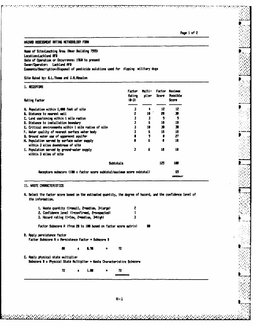
Page I of 2
HAZARD ASSESSOMN RATING IETNdOXf FORN
Nam of Sita:Leaching ~A (Near Building 7M9)LocationsLackland AFDate of Operation or Occurrence: MO~ to presentMower/Operatori Lackland AFBCmmnts/DescriptionsDisposal of pesticide solutions used faor dipping military dogs
Site Rated by: R.L.Thoum and J.R.Absalon
I. ECPTORSFactor Multi- Factor NaxlmRating plier Score Possible
Rat ing Factor 10-3) Score
A. Population wtithin I,'M feet of site 3 4 12 123L Distance to nearest wull 2 16 26 36C. Land use/zoning within I mile radius 3 3 9 9L. Distance to installation boundary 3 6 Is IsE. Critical environments within I mile radius of site 3 to 30 30F. Water quality of nearest surface water body 3 6 IS 1oG. Ground water use of uppermost aquifer 6 9 6 27H.L Population served by surface water supply 6 6 6 is
within 3 miles downstream of site1. Population served by ground-water supply 3 6 18 is
within 3 miles of site
Subtotals 125 i86
Receptors subscor (166 x factor score subtotal/maxim score subtotal) 69
If. WSE CHRCTERISTICS
A. Select the factor score based on the estimated quantity, the degree of hazard, and the confidence level ofthe information.
1. Waste quantity (Ismall, 2eedl., 3.largel 22. Confidence level (Isconfirmed, 2sspocted) I3. Hazard rating (1.ow, 2zmedium, 3igh) 3
Factor Subscore A (from 26 to IN based on factor score matrix) M
L. Apply persistence factorFactor Subscore A x Persistence Factor *Subscore 3
86 x 6.96 72
C. Apply physical state multiplier
Subscore B x Physical State Multiplier =Waste Characteristics Subscore -
72 x 1.08 2 72
H-1
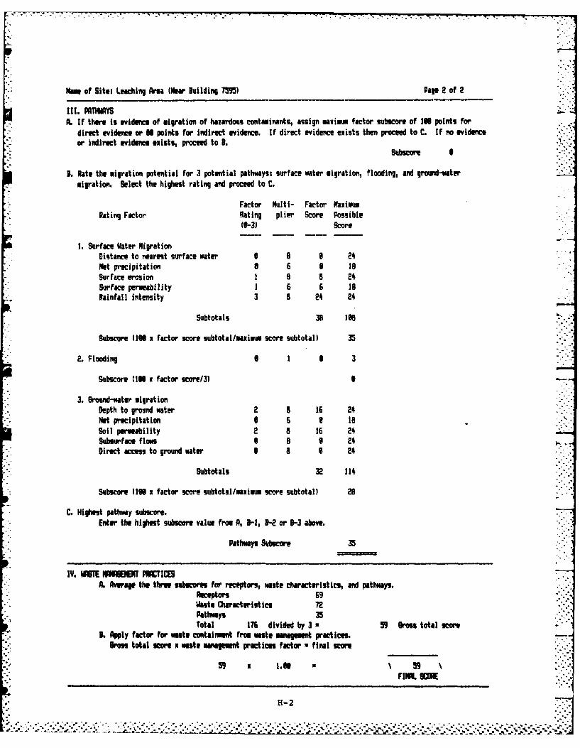
Name of Site: Leaching Area (Near Building 7M9) Pape 2 of 2
I 1. PATHWAYSA. If there is evidence of migration of hazardous contaminants, assign maximum factor subscore of 1IN points for
direct evidence or N points for indirect evidence. If direct evidence exists then procee to C. If no evidenceor indirect evidence exists, procee to B. .-
3. Rate the migration Potential for 3 potential pathways- surface water migration, flooding, and ground-watermigration. Select the highest rating and proceed to C.
Factor Multi- Factor MaximumRating Factor Rating plier Score Possible
(0-3) Score
1. Surface Water MigrationDistance to nearest surface water I a 6 24Met precipitation 3 6 9 N8Surface erosion I a a 24Surface permeability 1 6 6 18Rainfall intensity 3 a 24 24
Subtotals 38 168
Subscore (IN x factor score subtotal/maximm score subtotal) 35
2. Flooding 0 1 6 3
Subscore (IN x factor score/3)
* 3. Ground-water migrationDepth to ground wtater 2 8 16 24Net precipitation 6 6 1 toSoil permeability 2 a 16 24Subsurface f low 1 8 6 24Direct access to ground water 1 8 6 24
Subtotals 32 114
Subscore (1N x factor score subtotal/maximum score subtotal) 28
C. Highest pathway subscore.Enter the highest subscore value from A, 9-1, "- or 13-3 above.
Pathways Subscore 35
IV. WASTE IAS"( PRAC1IAi Average the three subicore for receptors, waste characteristics, and pathways.
Receptors 69Waste Characteristics 72Pathways 35Total 176 divided by3 a 59 Grosutotalscr
L. Apply factor for waste containment fro waste management practices.Boss total Rcor m waste management practices factor ufinal score
H- 2
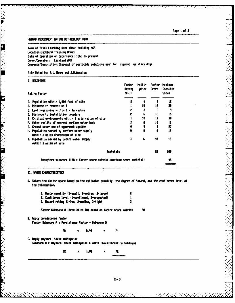
Pae I of 2
IHZA3 ASSESSMENT ITIN IETHO1DOLV FORM
Name of Site: Leaching Area (Near Building 4661LocationiLackland Training AnnexDate of Operation or Occurrence: 1%6 to presentOwnerlOperator: Lackland AFBCoomen ts/Description:Disposal of pesticide solutions used for dipping military dogs
Site Rated by: R.L.Thoem and J.R.Absalon
I. RECEPTORSFactor Multi- Factor MaximumRating plier Score Possible
IRating Factor (9-3) Score
IA. Population within l,@N feet of site 2 4 a 12B. Distance to nearest well I 1@ 1 39C. Land use/zoning within I mile radius 2 3 6 9D. Distance to installation boundary 2 6 12 19E. Critical environments within I mile radius of site I 1 1@ 38F. Water quality of nearest surface water body 3 6 186. Ground water use of uppermost aquifer S 9 6 27H. Population served by surface water supply 8 6 1 18
within 3 miles dowmstream of siteI. Population served by ground-water supply 3 6 1 18
within 3 miles of site
Subtotals 82 IN
Receptors subscore (1 N factor score subtotal/maxim score subtotal) 46
I. WASTE CIUCTERISTICS
A. Select the factor score based on the estimated quantity, the degree of hazard, and the confidence level ofthe information.
1. Waste quantity (Ismmall, 2amedim, 3large) 2. Confidence level flaconfirmed, 2suspected) I
H, Kazard rating (llot, 2Eaedium, 3shigh) 3
Factor Subscore A ime2 0 to 1l based on factor score matrix) N
B. Apply persistence factorFactor Subcore A x Persistence Factor Subscora 3
f x . 9 " 72
C. Apply physical state multiplierSubecor I x Physical State Multiplier W aste Characteristics Subscore
72 x 1.0 72
H-3
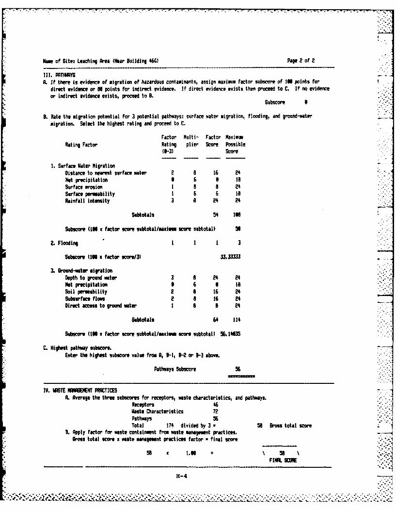
Name of Site: Leaching Area (Near Building 4661 Page 2 of 2
I 11. PATHWAYSA. If there is evidence of migration of hazardous contaminants, assign maximum factor subscre of IN6 points for
direct evidence or 80 points for indirect evidence. If direct evidence exists then proceed to C. If no evidenceor indirect evidence exists, proceed to 9.
Subscore I
9. Rate the migration potential for 3 potential pathways: surface water migration, flooding, and ground-watermigration. Select the highest rating and proceed to C.
Factor Multi- Factor MaximumRating Factor Rating plier Score Possible
(8-3) Score
1. Surface Water MigrationDistance to nearest surface water 2 8 16 2'.Net precipitation 1 9 18lSurface erosion I a 8 2'.Surface permeability 1 6 6 toRainfall intensity 3 8 2'. 2'.
Subtotals 5'. 1N
Subucoe (1IN x factor scor subtotal/mauium score subtotal) 56
2. Flooding I 1 1 3
Subscore (1IN x factor smor/31 U3333
3. Ground-water migrationDepth to ground water 3 a 2'. 24Net precipitation 6 6 6 ISoil permeability 2 8 16 2'.Subsurface flaw 2 a 16 2'.Direct access to ground water I a a 2'.
Subtotals 64 114.
Subscor (10O x factor score subtotal/maxim score subtotal) 56L 1'M
C. Highest pathway subscore.Enter the highest subscore value from A, 9-11 B-2 or 9-3 above.
Pathways Subscore 56
IV. WATE WHAUVAEET PRACTICESA. Average the three subscores for receptors, waste characteristics, and pathways.
Receptors 46Waste Characteristics 72Pathways 56Total 174. divided by 3. 58 gross total score
9. Apply factor for waste containment from waste management practices.Bross total score x waste management practices factor =final score
58 x 1.5\ 58
H-4
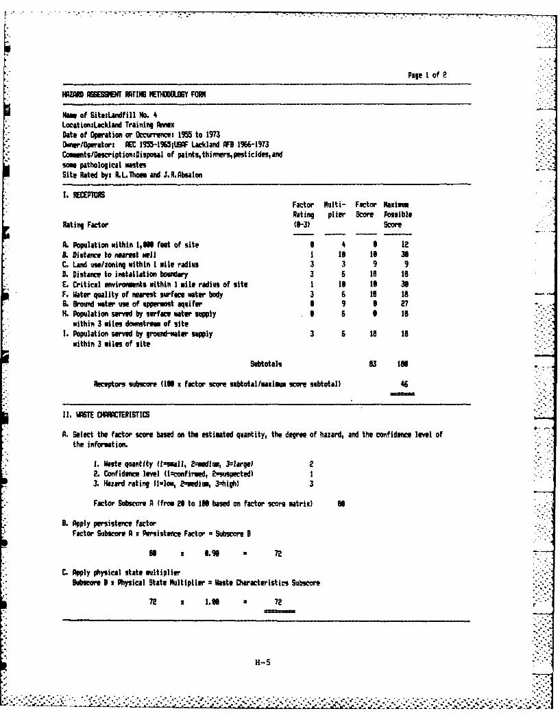
Page I of 2
*HZAR A9GESENU RATlIN EnhUOY FORM
Nam, of Site:Landf ill ND. 4Location:Lackland Training AnnexDate of Operat ion or Occurrence: 195 to 1973Ownaer/Operatori AEC 195-165*,USAF Lackland AFB 1966-1973ComentslDescript iorniDisposal of paints, thinners, pesticides, andsome pathological wastesSite Rated by: R.L.Thoeu auul J.R.Absalon
1. REmuTFactor Multi- Factor MaxiumRating plier Score Possible
Rating Factor 46-3) score
A. Population within 1,666 feet of site 6 4 6 12L. Distance to nearest well I t6 16 36C. Land use/zoning within I mile radius 3 3 9 9D. Distance to installation boundary 3 6 to to
*E. Critical mnvironments within I mile radius of site I is 16 36F. Water quality of nearest surface water body 3 6 18 Is0. Gmoud water use of uppermost aquifer 6 9 6 27H. Population served by surface water supply 6 6 6 Is
* within 3 miles downstream of site1 . Population served by ground-water supply 3 6 18 to
* within 3 miles of site
Subtotals 83 1In
Receptors subscore (106 x factor score subtotal/maxim.m score subtotall 46
11. WASTE CRISTICS
A. Select the factor score based on the estimated quantity, the degree of hazard, and the confidence level ofthe information.
1. gaste quantity i-saul, 2zoadium, Jlargel 22. Confidence level (lzconfirind, 2-suspected) I3. Hazard rating (lslow, 2--ediu, 3=high) 3
Factor Subscore A (from 28 to 1IN based on factor score matrix) U
B. Apply persistence factorFactor Subscore A x Persistence Factor Subscore B
Be x 1.968 72
C. Apply physical state multiplierguburoe 3 x Physical State Multiplier =Waste Characteristics Subscore,
72 x 1.66 72
H-5
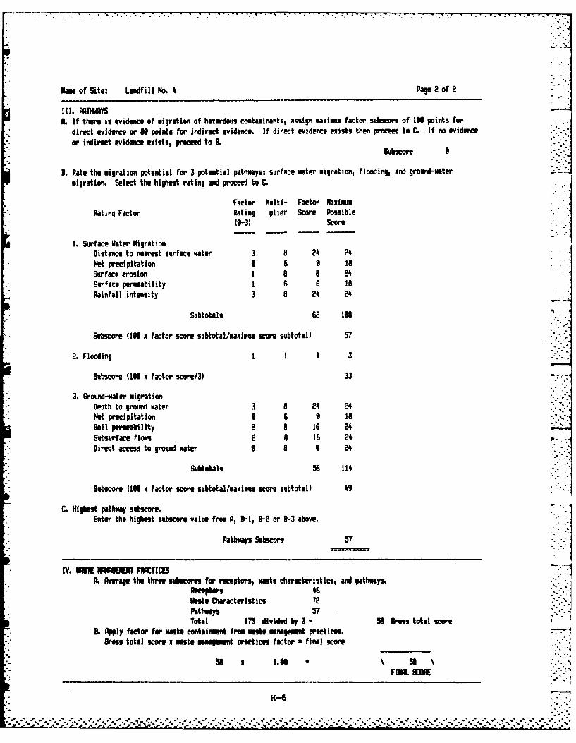
Nm of Site: Landfill No. 4 Pape 2 of 2
II1I. PpATys* A. If there is evidence of migration of hazardous contaminants, assign maxim factor subscore of 136 points for
direct evidence or 86 points for indirect evidence. If direct evidence exists then procee to C. If no evidenceor indirect evidence exists, proceed to B.
Subicor I -
9 . Rate the migration potential for 3 potential pathways.- surface water migration, flooding, and ground-watermigration. Select the highest rating and preed to C.
Factor Multi- Factor MaximumRating Factor Rating plier Score Possible
(0-3) Score
1. Surface Water MigrationDistance to nearest surface water 3 8 24 24Net precipitation 6 6 0 18Surface erosion I a 8 24Surface permeability, 1 6 6 19Rainfall intensity 3 a 24 24
Subtotals 62 lea.
Subscore 0*6 x factor score subtotal/maxiom score subtotal) 57
*2. Flooding 1 1 1 3
Subscore (18 x factor score/3) 33
3. Ground-water migrationDepth to ground water 3 8 24 24Net precipitation 6 6 6 18Soil permeability 2 8 16 24Subsurface flows 2 8 16 24Direct aces to ground water 0 8 24
Subtotals 56 114
Subscore (1IN x factor score subtotal/maxium. score subtotal) 4
C. Highest pathway subscore.Enter the highest subscore value from A, 0-1, B-2 or B-3 above.
Pathways Subscore 57
* IV. WIMT MAGBIN PRACTICESL. Average the three subscores for receptors, waste characteristics, and pathways.
Receptors 46Waste Characteristics 72Pathway% 57Total 175 divided by 3 z56 Gras total score
3L Apply factor for wate containment fro muate managemt practices.Bross total scOre X waste anagement Practices factor ufinal scor
56 1.38 56 NFI14L SOE
H-6
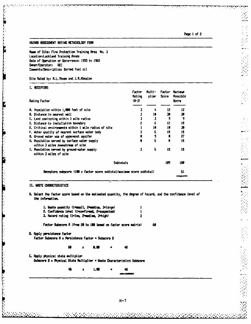
Page 1 of 2
IZARD ASSESSlENT RAT ING NTHMOGY FORK
Name of Sites Fire Protection Training Area No. 3Location:Lackland Training AnnexDate of Operation or Occurrence: 19. to 1%950mnerlOperator: AECComments/Description: Burned fuel oil
Site Rated by: R.L.Thoem and J.R.Absalon
I. RETPTORSFactor Multi- Factor MaximoRating plier Score Possible
Rating Factor (1-3) Score
A. Population within 1,96 feet of site 3 4 12 12B. Distance to nearest wall 3 16 36 36C. Land use/zoning within I mile radius 3 3 9 90. Distance to installation boundary 2 6 12 18E. Critical enviroments within I mile radius of site I 1 16 30F. Water quality of nearest surface water body 3 6 18 186. 6round water use of uppermost aquifer 0 9 6 27H. Population served by surface water supply 6 6 6 18
within 3 miles downstream of siteI. Population served by ground-water supply 3 6 is 1
within 3 miles of site
Subtotals 19 IN
Receptors subscore (IN factor score subtotal/maxim score subtotal) 61
II. WASTE COIRCTRISTICS
A. Select the factor score based on the estimated quantity, the degree of hazard, and the confidence level ofthe informat ion.
I. Waste quantity (lsmall, 2memdi, 3=large) I2. Confidence level (lUconfirmd, 2suspected) I3. Hazard rating (Izlow, 2medim, 3=high 3
Factor Subscore A (from l to IN based on factor score matrix) 68
. Apply persistence factorFactor Subscore A x Persistence Factor u Subscore 3
61 x L.6 U 48
C. Apply physical state multiplierSubscore 8 x Physical State Multiplier W aste Characteristics Subscore
46 x I.N 48
H-7
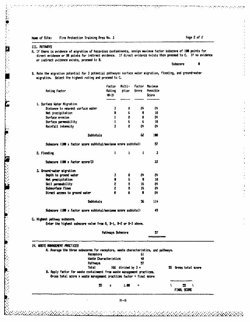
Name of Site: Fire Protection Training Area No. 3 Page 2 of 2
Ill. PATHWAYSA. If there is evidence of migration of hazardous contaminants, assign maximum factor subscore of IN points for
direct evidence or 88 points for indirect evidence. If direct evidence exists then proceed to C. If no evidence
or indirect evidence exists, proceed to B.Subscore I
9. Rate the migration potential for 3 potential pathways: surface water migration, flooding, and ground-water
migration. Select the highest rating and proceed to C.
Factor Multi- Factor MaximumRating Factor Rating plier Score Possible
(18-3 Score
I. Surface Water MigrationDistance to nearest surface water 3 8 24 24
Net precipitation 0 6 8 18Surface erosion 1 8 8 24Surface permeability 1 6 6 18Rainfall intensity 3 a 24 24
Subtotals 62 198
Subucore (IN x factor score subtotal/maximum score subtotal) 57
2. Flooding 1 3
Subscore (I x factor score/3) 33
3. Ground-water migratlonDepth to ground water 3 8 24 24Net precipitation 8 6 8 18Soil pemeability 2 8 16 24Subsurface flows 2 a 16 24Direct access to ground water I 8 I 24
Subtotals 56 114
Subcore (10 x factor score subtotal/maxim score subtotal) 49
C. Highest pathway subseore.Enter the highest subscore value from A, B-1, B-2 or B-3 above.
Pathways Subscore 57
IV. WASTE PGEENT PICTICES. Average the three subscores for receptors, waste characteristics, and pathways.
Receptors 61Waste Characteristics 48Pathways 57Total 166 divided by 3 :55 ross total scoe
B. Apply factor for waste containment from waste management practices.Gross total score x waste management practices factor final score
55 x 1,H . 55 NFINL SCORE
H-8
_, .,, .:., .. ,.. .. ,_;:...-. ,-..?.,-. ,,'.:.-_ . :..;,,.,............-............,.........,...,..,..,,.....-..-,...,.......-.,.
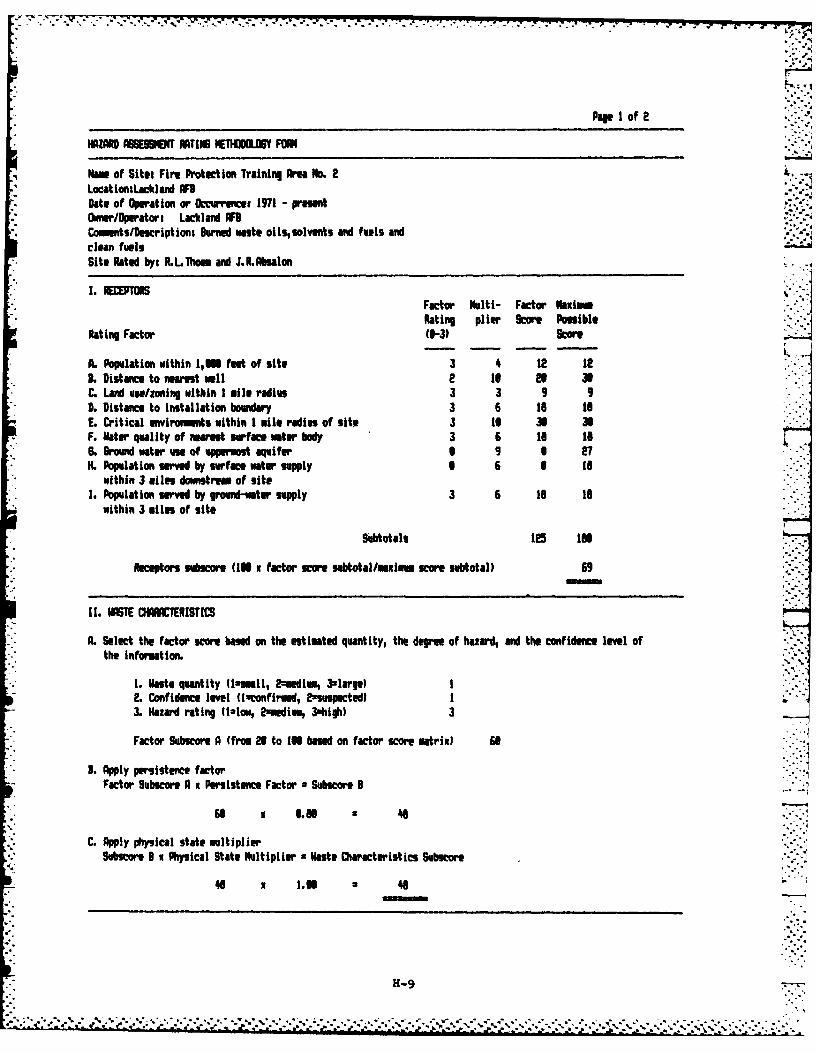
Page I of 2
- ~ HZARD ASSESION ARTINS IHTIDIU FORM
Name of Site: Fire Protection Training Aee No. 2LocatlonsLackland AFI. .Dateao pr ionw or Omvu s 171 prsenOwnr/Opuratori Lackland WD
* Commnts/Descriptiont Burned waste oilssolvents eand fuels andclean fuels
* Sit@ Rated by: R.LThoem and J.R.Nbslon
1 .WDEPRSFactor Nulti- Factor H1aul..Rating p11ev' Score Possible
Rating Factor 1-3) Score
A. Population within 1I66 fa.t of site 3 12 1e iL. Distance to nearest well 2 is El is
*C. Land use/zonIng within I mile Padius 3 3 9 9L. Distance to installation boundary 3 6 is toE. Critical ewwivonts within I mile radius of uite 3 10 3 XF. Mtr quality of nearedstuface wter' body 3 6 le IsS. B.rand water asof uppmost aquifer 1 9 1 27
*H. Population seved by surface water supply 6 6 0 t8* within 3 miles downstrom, of site
1. Population served by ground-water supply 3 6 le 18within 3 miles of site
Subotals 15 186
Receptors svbscar (186x factor scare subtotil/uuximin score subtotal) 69
WA ISTE OIUACTEISTIVS
A. Select the factor score based on the estimated quantity, the degree of hazard, and the confidence level ofthe information.
1. Waste quantity Ilmseall, 2mmed1u, 3slargu)2. Confidence level Unconfirmed, tisuspectedl3. Hazard rating (1Iow, 2mmdim, 3*high) 3
Factor Subscore A (from 26 to 166 based on factor scare mtrix) fit
* 3. Apply persistence factor-Factor Subscare A x Persistence Factor. Subscore 8
* C. Apply phiysical state muliplier
* Subscore B x Physical Stats Nultipliur sWaste Characteristics Subucor
H-9-
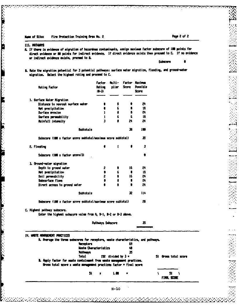
Nam of Site: Fire Protect ion Training Ame No. e Pag e 2of 2
* A. If thuan is evidence of migration of hazardous contaminants, assign maximum factor subseorm of 10 points for* direct evidence or U points for indirect evidence. 1f direct evidence euists then proceed to C. If no evidence* or indirect evidence exists, proceed to 3.
SubewcarI
3. Rate the migration potential for 3 potential pathwayst surface water migration, flooding, and ground-water* migration. Select the highest rating and prce to C.
Factor Multi- Factor NaimRating Factor Rating plier Score Possible
(0-3)Score
1. Surface Water igrationDistance to nearest surface water 1 6 9 24Not precipitation S 6 S toSurface erosion 1 a aSurface permeability 1 6 6 toRainfall intensity 3 8 24 24
Subtotals 38 I38
Subscore (138 x factor score subtotallmuimon score subtotall 35
L 2 Flooding I 1 6 3
Subscore 1l1S x factor score13) -
* 3. Ground-wter migrationDepth to ground water 2 8 16 24Net precipitation 6 6 8 ISSoil permeability 2 8 16 24-Subsurface flIows 1 8 24Direct access to ground water 1 8 24
Subtotals 32 114
Subscore (10 x factor score subtotal/muimu score subtotal) 28
C. Highest pathway subscore.Enter the highest subucore value from A, 31, H- or 31-3 above.
Pathways Subucore 33
IV. MRE EEM91T PRACTICES -
L. Average the three sebscore for receptoris, waste characteristics, and pathways."ecestor
Vast@ Characteristics 48Pathways 35Total 152 divided by 3 51 Gross total scor
L. Apply factor for waste containment from as managment practices.boss total KW@r N waste mafaemet practices factor f ifil Rore
5i x 1.16 51 N
H-10
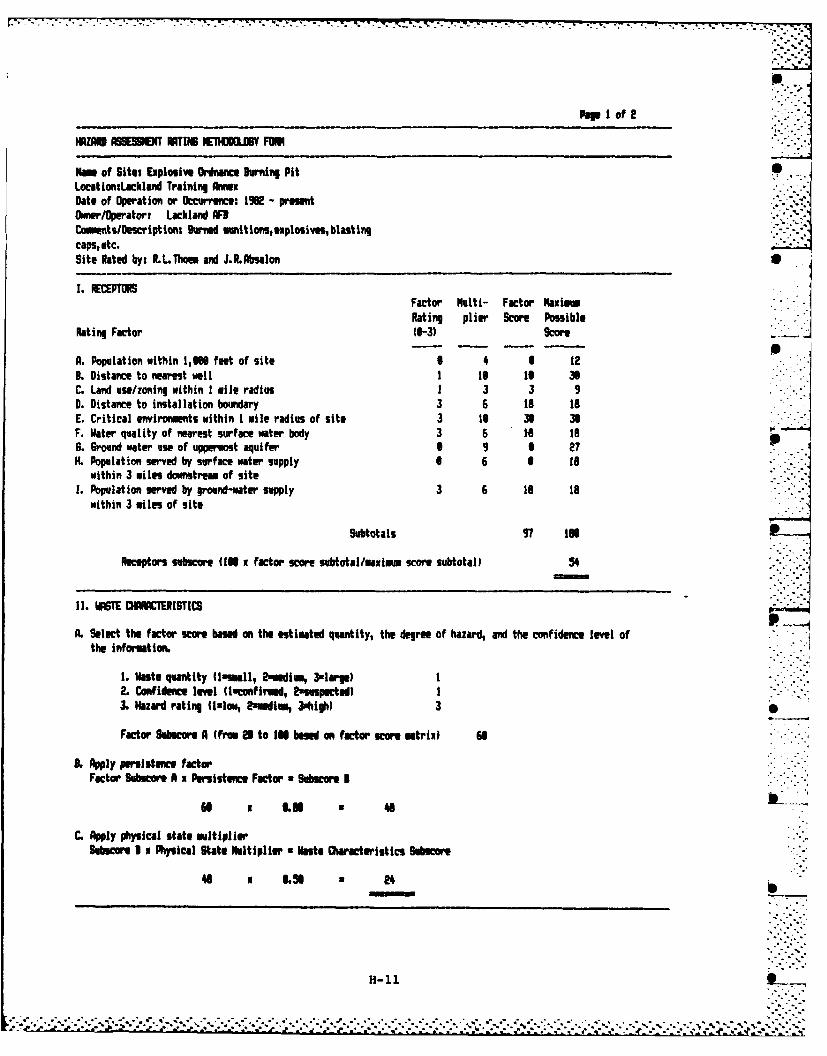
pops I of 2
HZARD ASBEIGIEN RTINE NEn1ODOLY FOR
Nae of Situs Explosive Ordnance Drning PitLocatlontLachland Training bmnexDate of Operation or Occurrence. 1992 - presentIfiner/peratori Lackland AFBCommeots/Descript ions Burned munitions, explosives, blast ingcaps, etc.Site Rated by: R.L.Thoem and J.R.Absalon
1. RECEPTORSFactor Multi- Factor Naximn. JRating plier Score Posible
Rating Factor (0-3) score
A. Population within 1,616 feet of site 9 4 6 123. Distance to nearest well I 16 16 3C. Land use/zoning within I mile radius 1 3 3 9D. Distance to installation boundary 3 6 is 18E. Critical environments within I mile radius of site 3 to 3 3F. Water quality of nearest surface water body 3 6 to toS. ground water use of uppermost aquifer S 9 9 27H. Population served by surface water supply 9 6 S t8
within 3 miles downstream of site1. Population served by ground-water supply 3 6 1o 18
within 3 miles of site
Subtotals 97 in
Receptors subscore IM6 x factor score subtotal/aim score subtotal) 54
II. WASTE OCAERISTICS
A. Select the factor score based on the estimated quantity, the degree of hazard, and the confidence level ofthe information.
I. Waste quantity flummall, Zomdium, Nolrge) I2. Confidence level (loconfirmed, easespucted)I3. Hazard rating f1.1.., Pumedimm, 3ohigh) 30
Factor Sulocore A (from 25 to IN based on factor score matrix) 61
3.Apply Persistence factorFactor Subscar A x Persistence Factor uSubue B
61 Is &N6 46
C. Apply physical state multiplierSubscore I x Physical State Mltiplier uWaste Owaecteristics Subscore
46 a .~ * 24
H-11 I
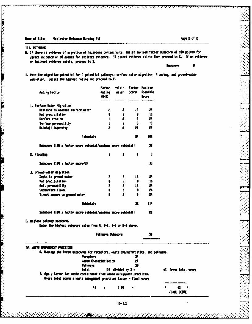
- . - - ..-
Nam of Site: Explosive Ordnance urning Pit Pap 2 of 2
III. IMM"A. If there is evidence of migration of hazardous containants, assign maxim factor subscore of I points for
direct evidence or 0 points for indirect evidence. If direct evidence exists then poc to C. If no evidenceor indirect evidence exists, proceed to B.
Subscore I
B. Rate the migration potential for 3 potential pathways: surface water migration, flooding, and groundi-twatermigration. Select the highest rating and poc to C.
Factor Multi- Factor MaximumRating Factor Rating plier Score Possible
(0-3) Score
I. Surface Water Nigration 71'
Distance to nearest surface water 2 8 16 2'Met precipitation 6 6 6 1Surface erosion 1 8 8 2Surface permeability 1 6 6 isRainfall intensity 3 8 24 24-
Subtotals 54 Ila9
Subucor (IN x factor score subtotalmaximum score subtotal) 51
: 2. Flooding 1 1 1 3
Subcore (110 x factor score/3) 33
3. &ud-wter migrationDepth to roud water 2 8 16 2. --vMt precipitation 6 6 6 18Soil Imeability 2 8 16 24S b face fl ss 6 6 2'.Direct acess to ro twater I N--
Sumotals 2 11''
Subsare 10 x factor sor sustotal/mism score subtotal 1 21
C. Hioet pathway su beo.Enter the highest smecre valu fro A, -H, H or 3-3 above.
Pathways subscoreU
IV. 011TE S IUBEf POCTII-,. Average the three sebecas for receptors, aste characteristic , ad pathw.ays.
Receptors 5'.Onte Characteristics 2'4 "-:pathways U --Total 126 divided by 3 '43 Bros total score
. Apply factor for maste contaiusent fro waste management practices.Dross total score x waste mnament practices factor • final score
4.3 1. N~g :'3FIL UM
H- 12C ... **~*~*. . .. . . .. . . .. . . . . .. ,...
-. . . ....!A....~ .
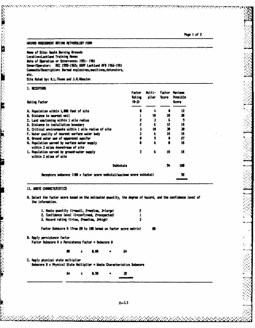
Page I of 2
* ~ AZR mzm Isuo P MEETNMLC6Y FDU
* Name of Sit eta Brning Grounds* LacationtLacklani Training Ann~ex
Onto of Operation or Occurrence: 1951- 1901Ownerfllperatort AEC 19I9651S UWF Lackland AF8 1966-1981CammntslDscript ion, Burned explouives,munit ions, detonators,etc.Site Rated byi R.L.Toem andi J.R.Abmalon
1.-Factor Nulti- Factor NoxiousRating plier Score Possible
Rating Factor 10-3) Score
L. Population within 1,11 feet of site 3 4 S 123. Distance to nerest well I is Is 38C. Land urn/zoning within I mile radius 2 3 6 90. Distance to installation boundary 2 6 12 toE. Critical unvironimmts within I mile radius of site 3 It 36 33F. Water quality of nearest surface water body 3 6 is toL Srond wateruwe of uppermostaquifer 6 9 6 27H. Population served by surface water supply 6 6 3 Is
within 3 miles downstream of mite1. Population serve by ground-water supply 3 6 to Is
within 3 miles of mite
subtotals 94 In
Receptors subucore 110 x factor score subtotal/mai..e score subtotal)
11. MASlE CHARCTERISTICS
A. Select the factor score based on the estimated quantity, the degree of hazard, and the confidence level ofthe information.
1. Waste quantity (Issmail, 2needium, 3slarle) 22. Confidence level Un~confirmed, 2umumpected) I3. Hazard rating (tmlow, 2amedlm, 3ohlgh) 3
Factor Subucore A (from e3 to IN based on factor score matrix) M
3L Apply persistence factorFactor Subscoref A xPersistence Factor uSubscore 3
N x LU 64
C. Apply physical state multiplierSubscore B x Physical State Multiplier uWaste Characteristics Subscore
64 1 6.9 3e
H-1l3
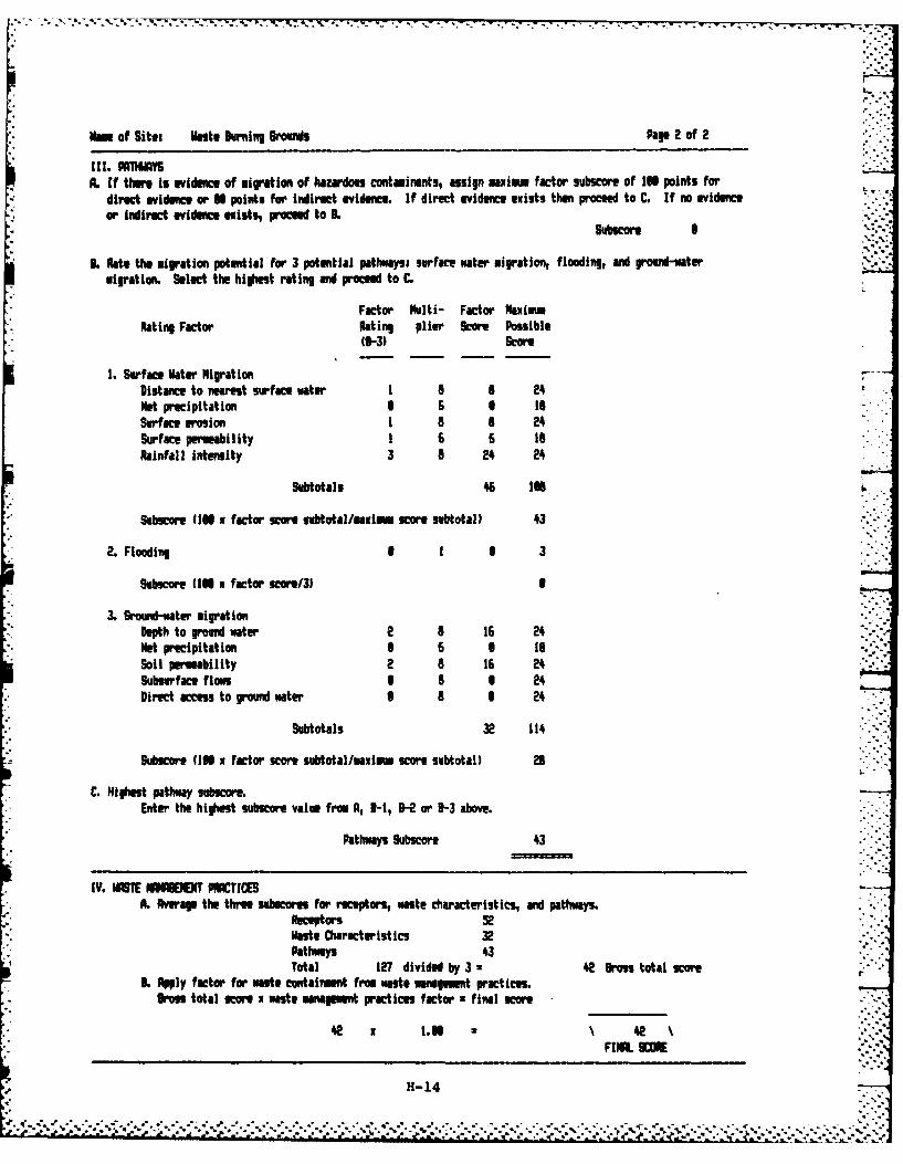
SNome of Site: uanto During &rouns Pap 2 of 2
A. If there is evidence of migration of hazardous contaminants, assign axioam factor subseor of 136 points for* direct evide or U points for indirect evidence. If direct evidence exists then proceed to C. If no evidence
or iiwfrect vdm uiden exst, roed to 3.
1 . Rate the migration potential for 3 potential pathways: surface water migration, flooding, and ground-watermigration. Select the highest rating and proceed to C.
Factor Multi- Factor MaximumRating Factor Rating plier Score Possible
(0-3) Score
1. Surface Hater MigrationDistance to nearest surface water I a a 24Net precipitation 9 6 S toSurface erosion I a a 24Surface permeability 1 6 6 isRainfall intensity 3 a 2* 24
Subotals 46 136
Sabse (15 it factor score subtotal/auim scoe. subtotal) 43
*2. Flooding I 1 S 3
Subucore (1IN x factor score31
* 3. Ground-water migrationDepth to rowd water 2 a 16 24Net precipitation S 6 S IsSoil Permeability 2 a 16 2*Subsurface flow I S 0 24Direct access to ground water I a S 2*
Subtotals 32 114
Subscore, (10 x factor score subtotal/mauimu score subtotal) 25
C. Highest pathway subscore.Enter the highest subscore value from A, 8-1, H- or B-3 above.
Pathways 9ubscore 43
IV. lISTE WNBWW PWC(SA. Average the three suhscome for receptors, waste characteristics, and pathways.
Receptors 52Ha Characteristics 3Pathways *3Total 127 divided by 3 z2 grossitotal score f
3L Apply factor for taste containment fro waste management practices.Oross total Kwor n Wase management practices factor *final score
42 x 1.55 N 42 '
FNA 9KDM
H-14
APPENDIX I
GLOSSARY OF TERMINOLOGY AND ABBREVIATIONS
APPENDIX I
GLOSSARY OF TERMINOLOGY AND ABBREVIATIONS
ABG: Air Base Group
ACFT MAINT: Aircraft Maintenance.
AEC: Atomic Energy Commission
AF: Air Force.
AFB: Air Force Base.
AFESC: Air Force Engineering and Services Center.
AFFF: Aqueous Film Forming Foam, a fire extinquishing agent. AFFF .°concentrates includes fluorinated surfactants plus foam stabilizers
diluted with water to a 3 to 6% solution.
AFR: Air Force Regulation.
Ag: Chemical symbol for silver.
AGE: Aerospace Ground Equipment.
Al: Chemical symbol for aluminum.
ALLUVIUM: Materials eroded, transported and deposited by streams.
ALLUVIAL FAN: A fan-shaped deposit formed by a stream either where itissues from a narrow mountain valley into a plain or broad valley, orwhere a tributary stream joins a main stream.
ANTICLINE: A fold in which layered strata are inclined down and awayfrom the axes.
AQUICLUDE: Poorly permeable formation that impedes ground-water move-ment and does not yield to a well or spring.
AQUIFER: A geologic formation, group of formations, or part of a forma-tion that is capable of yielding water to a well or spring.
AQUITARD: A geologic unit which impedes ground-water flow.
ARENACEOUS: Sand-bearing or sandy; containing sand-sized particles.
ARGILLACEOUS: Composed of clay minerals or clay-sized particles.
I-i
-' ',A ~ .'', - ..- '- ,* -... ' .. - - .'... ." -.'-." - .. -. .. -. -*.... .,-. ,..'.-.: -.'. ", .. .'- -. -, -'.L . ... ',,... -.•.,- "-
7 -
AROMATIC: Description of organic chemical compounds in which the carbonatoms are arranged into a ring with special electron stability asso-ciated. Aromatic compounds are often more reactive than non-aromatics.
ATC: Air Training Command.
ARTESIAN: Ground water contained under hydrostatic pressure.
AUTOCLAVE: A method of sterilization by superheated steam under pres-sure.
AVGAS: Aviation Gasoline.
Ba: Chemical symbol for barium.
BALCONES ESCARPMENT: The long, relatively continuous steeply slopinggeomorphological feature formed by faulting that separates the EdwardsPlateau (north) from the West Gulf Coastal Plain (south). The EdwardsPlateau forms the upper escarpment surface, while the Coastal Plaindefines the lower escarpment limits.
BEE: Bioenvironmental Engineer.
BES: Bioenvironmental Engineering Services.
BIOACCUMULATE: Tendency of elements or compounds to accumulate or buildup in the tissues of living organisms when they are exposed to theseelements in their environments, e.g., heavy metals.
BIODEGRADABLE: The characteristic of a substance to be broken down fromcomplex to simple compounds by microorganisms.
BOWSER: A portable tank, usually under 200 gallons in capacity.
BX- Base Exchange.
CaCO3 : Chemical symbol for calcium carbonate. 4
CALICHE: Gravel, sand, silt or clay cemented by soluble calcium saltsto form a crust or hard layer. A term used to describe a broad varietyof "hard pan" conditions in the southwest U.S.
CAMS: Consolidated Aircraft Maintenance Squadron.
CARBON 14: A radionuclide with a 5730 year half-life.
Cd: Chemical symbol for cadmium.
CE: Civil Engineering.
CEIA: Comprehensive Environmental Response, Compensation and Liabili-ty Act.
CERIUM 144: A radionuclide with a 284 day half-life.
1-2
-. -: .'.* Z
CES: Civil Engineering Squadron.
CESIUM 137: A radionuclide with a 30 year half-life.
CHERTY: A precipitated cryptocrystalline silicate rock material.Occurs chiefly as nodules or concretions within a host rock.
CHLORDANE: An insecticide.
CIRCA: About; used to indicate an approximate date.
CLOSURE: The completion of a set of rigidly defined functions for ahazardous waste facility no longer in operation.
CN: Chemical symbol for cyanide.
COD: Chemical Oxygen Demand, a measure of the amount of oxygen required
to oxidize organic and oxidizable inorganic compounds in water.
COE: Corps of Engineers.
CONFINED AQUIFER: An aquifer bounded above and below by impermeablestrata or by geologic units of distinctly lower permeability than thatof the aquifer itself.
CONFINING UNIT: An aquitard or other poorly permeable layer whichrestricts the movement of ground water.
CONTAMINATION: The degradation of natural water quality to the extentthat its usefulness is impaired; there is no implication of any specificlimits since the degree of permissible contamination depends upon theintended end use or uses of the water.
Cr: Chemical symbol for chromium.
Cu: Chemical symbol for copper.
CURIE: Unit for measuring radioactivity. One rie is the quantity ofany radioactive isotope wndergoing 3.7 x 10 disintegrations persecond.
DDD: 2,2-bis (para-chlorophenyl) - 1,1-dichloroethane. An insecticide.Insoluble in water.
DDT: Dichlorodiphenyltrichloroethane. An insecticide. Insoluble inwater.
DET: Detachment.
2,4-D: Abbreviation for 2,4-dichlorophenoxyacetic acid, a common weedkiller and defoliant.
DIP: The angle at which a stratum is inclined from the horizontal.
1-3
• i '"" " • "" ."". •" ".."- "" . .'" . *"" . "" " . "" . -" .""" ;. . -" . -" ."-"-" . ." ."-" .--.. ."..."-. , " ." -.... - '. '.-..'.-
DISPOSAL FACILITY: A facility or part of a facility at which hazardouswaste is intentionally placed into or on land or water, and at whichwaste will remain after closure.
DISPOSAL OF HAZARDOUS WASTE: The discharge, deposit, injection, dump-ing, spilling, or placing of any hazardous waste into or on land orwater so that such waste or any constituent thereof may enter the envi-ronment or be emitted irr.o the air or discharged into any waters, in-cluding ground water.
DO: Dissolved oxygen.
DOD: Department of Defense.
DOWNGRADIENT: In the direction of decreasing hydraulic static head; thedirection in which ground water flows.
DPDO: Defense Property Disposal Office.
DUMP: An uncovered land disposal site where solid and/or liquid wastesare deposited with little or no regard for pollution control or aesthe-tics; dumps are susceptible to open burning and are exposed to theelements, disease vectors and scavengers.
EFFLUENT: A liquid waste discharge from a manufacturing or treatmentprocess, in its natural state, or partially or completely treated, that ",discharges into the environment.
EO,: Explosive Ordnance Disposal.
EP: Extraction Procedure, the EPA's standard laboratory procedure forleachate generation.
EPA: U.S. Environmental Protection Agency.
EPHEMERAL AQUIFER: A water-bearing zone typically located near thesurface which normally contains water seasonally.
EROSION: The wearing away of land surface by wind, water, or chemicalprocesses.
ES: Engineering-Science, Inc.
FAA: Federal Aviation Administration.
FACILITY: Any land and appurtenances thereon and thereto used for thetreatment, storage and/or disposal of hazardous wastes.
FAULT: A fracture in rock along which the adjacent rock surfaces aredifferentially displaced.
Fe: Chemical symbol for iron.
1-4
* . . . . ..- .. -- . - . . . .. ,
FLOOD PLAIN: The lowland and relatively flat areas adjoining inland andcoastal areas of the mainland and off-shore islands, including, at aminimum, areas subject to a one percent or greater chance of flooding inany given year.
FLOW PATH: The direction or movement of ground water as governed prin-cipally by the hydraulic gradient.
FMS: Field Maintenance Squadron.
FPTA: Fire Protection Training Area.
FTW: Flying Training Wing.
GC/MS: Gas chromatograph/mass spectrophotometer, a laboratory procedurefor identifying unknown organic compounds.
GLACIAL TILL: Unsorted and unstratified drift consisting of clay, sand,gravel and boulders which is deposited by or underneath a glacier.
GROUND WATER: Water beneath the land surface in the saturated zone thatis under atmospheric or artesian pressure.
GROUND WATER RESERVOIR: The earth materials and the intervening openspaces that contain ground water. -
HALF-LIFE: The time required for half the atoms present in radioactivesubstance to disintegrate.
HALOGEN: The class of chemical elements including fluorine, chlorine,bromine, and iodine.
HARDFILL: Disposal sites receiving construction debris, wood, miscel-laneous spoil material.
HARM: Hazard Assessment Rating Methodology.
*HAZARDOUS SUBSTANCE: Under CERCLA, the definition of hazardous sub-stance includes:
1. All substances regulated under Paragraphs 311 and 307 of theClean Water Act (except oil);
2. All substances regulated under Paragraph 3001 of the Solid WasteDisposal Act;
3. All substances regulated under Paragraph 112 of the Clean AirAct;
4. All substances which the Administrator of EPA has acted againstunder Paragraph 7 of the Toxic Substance Control Act;
5. Additional substances designated under Paragraph 102 of theSuperfund bill.
1-5
* .*.*. b~ *- N. * ** -* ** -* .- - . . . . . . . . . ..
*HAZARDOUS WASTE: As defined in RCRA, a solid waste, or combination of
solid wastes, which because of its quantity, concentration, or physical,chemical or infectious characteristics may cause or significantly con-tribute to an increase in mortality or an increase in serious, irrever-sible, or incapacitating reversible illness; or pose a substantialpresent or potential hazard to human health or the environment whenimproperly treated, stored, transported, or disposed of, or otherwisemanaged.
HAZARDOUS WASTE GENERATION: The act or process of producing a hazardouswaste.
HEAVY METALS: Metallic elements, including the transition series, whichinclude many elements required for plant and animal nutrition in traceconcentrations but which become toxic at higher concentrations.
Hg: Chemical symbol for mercury.
HQ: Headquarters.
HWAP: Hazardous Waste Accumulation Point.
HYDROCARBONS: Organic chemical compounds composed of hydrogen andcarbon atoms chemically bonded. Hydrocarbons may be straight chain,cyclic, branched chain, aromatic, or polycyclic, depending upon arrange-ment of carbon atoms. Halogenated hydrocarbons are hydrocarbons inwhich one or more hydrogen atoms has been replaced by a halogen atom.
INCOMPATIBLE WASTE: A waste unsuitable for commingling with anotherwaste or material because the commingling might result in generation ofextreme heat or pressure, explosion or violent reaction, fire, formationof substances which are shock sensitive, friction sensitive, or other-wise have the potential for reacting violently, formation of toxicdusts, mists, fumes, and gases, volatilization of ignitable or toxicchemicals due to heat generation in such a manner that the likelihood ofcontamination of ground water or escape of the substance into the envi-ronment is increased, any other reaction which might result in notmeeting the air, human health, and environmental standards.
INFILTRATION: The movement of water through the soil surface into theground.
IRP: Installation Restoration Program. L
ISOPACH: Graphic presentation of geologic data, including lines ofequal unit thickness that may be based on confirmed (drill hole) data orindirect geophysical measurement.
* For purposes of this Phase I IRP report hazardous substances and haz-ardous wastes are considered synonymous.
1-6
ISOTOPE: Two or more species of atoms of the same chemical element,with the same atomic number and place in the periodic table, and nearlyidentical chemical properties, but with different atomic mass numbersand different physical properties; an example may be the radioactiveisotope - Carbon (12) and Carbon-14.
JP-4: Jet Propulsion Fuel Number Four, military jet fuel.
LEACHATE: A solution resulting from the separation or dissolving ofsoluble or particulate constituents from solid waste or other man-placedmedium by percolation of water.
LEACHING: The process by which soluble materials in the soil, such asnutrients, pesticide chemicals or contaminants, are washed into a lowerlayer of soil or are dissolved and carried away by water.
LENTICULAR: A bed or rock stratum or body that is lens-shaped.
LINER: A continous layer of natural or man-made materials beneath or onthe sides of a surface impoundment, landfill, or landfill cell whichrestricts the downward or lateral escape of hazardous waste, hazardouswaste constituents or leachate.
LITHOLOGY: The description of the physical character of a rock.
LOESS: An essentially unconsolidated unstratified calcareous silt;commonly homogeneous, permeable and buff to gray in color.
LOX: Liquid oxygen.
LYSIMETER: A vacuum operated sampling device used for extracting porewater samples at various depths within the unsaturated zone.
M: Milli (i0)
MARL: An earthy substance consisting of 35-65% clay and 65-35% carbo-nate, formed as a result of calcium carbonate precipitation and clayparticle sedimentation.
MEK: Methyl ethyl ketone.
METALS: See "Heavy Metals".
ug/l: Micrograms per liter.
mg/l: Milligrams per liter.
MGD: Million gallons per day.
MIBK: Methyl isobutyl ketone.
-6MICRO: u (10 - )'
1-7 "-4°-"
MOGAS: Motor gasoline. -
Mn: Chemical symbol for manganese.
MONITORING WELL: A well used to measure ground-water levels and toobtain samples.
MSL: Mean Sea Level.
MWR: Morale, Welfare and Recreation.
NCO: Non-commissioned officer.
NCOIC: Non-commissioned Officer In-Charge.
NDI: Non-destructive inspection.
NET PRECIPITATION: The amount of annual precipitation minus annualevaporation.
NGVD: National Geodetic Vertical Datum of 1929. A national datumsystem, tied to Mean Sea Level, but referenced primarily to land-basedbenchmarks.
Ni: Chemical symbol for nickel.
NOAA: National Oceanic and Atmospheric Administration.
NPDES: National Pollutant Discharge Elimination System.
NRC: Nuclear Regulatory Commission
OEHL: Occupational and Environmental Health Laboratory.
OIC: Officer-In-Charge.
OMS: Organizational Maintenance Squadron.
ORGANIC: Being, containing or relating to carbon compounds, especiallyin which hydrogen is attached to carbon.
OSI: office of Special Investigations.
OTS: officer Training School.
O&G: Symbols for oil and grease.
Pb: Chemical symbol for lead.
PCB: Polychlorinated Biphenyll liquids used as a dielectrics in elec-trical equipment. . ...-
PD-680: Cleaning solvent, petroleum distillate, Stoddard solvent.
1-8
PERCHED WATER TABLE: A water table above a relatively impermeable zone-underlain by unsaturated rocks of sufficient permeability to allowground-water movement.
PERCOLATION: Movement of moisture by gravity or hydrostatic pressurethrough interstices of unsaturated rock or soil.
PERMEABILITY: The capacity of a porous rock, soil or sediment fortransmitting a fluid without damage to the structure of the medium.
PERSISTENCE: As applied to chemicals, those which are very stable andremain in the environment in their original form for an extended periodof time.
PESTICIDE: An agent used to destroy pests. Pesticides include suchspecialty groups as herbicides, fungicides, insecticides, etc.
PETN: Pentaerythritol tetranitrate. An explosive which is soluble inwater.-•
PH: Negative logarithm of hydrogen ion concentration.
Pico: 1012
PL: Public Law.
POL: Petroleum, Oils and Lubricants.
POLLUTANT: Any introduced gas, liquid or solid that makes a resourceunfdit for a specific purpose.
POLYCYCLIC COMPOUND: All compounds in which carbon atoms are arrangedinto two or more rings, usually aromatic in nature.
POTENTIALLY ACTIVE FAULT: A fault along 'which movement has occurredwithin the last 25-million years.POTENTIOLETRIC SURFACE: The imaginery surface to which water in an
artesian aquifer would rise in tightly screened wells penetrating it.
ppb: Parts per billion by weight.
ppm: Parts per million by weight.
PRECIPITATION: Rainfall.
QUATERNARY MATERIALS: The second period of the Cenozoic geologic era,following the Tertiary, and including the last 2-3 million years.
RCRA: Resource Conservation and Recovery Act.
RDX: Cyclonite. An explosive consisting of hexahydro-trinitro-tri-azine.
1-9 -
RECEPTORS: The potential impact group or resource for a waste contami-nation source.
RECHARGE AREA: A surface area in which surface water or precipitationpercolates through the unsaturated zone and eventually reaches the zoneof saturation. Recharge areas may be natural or marnmade.
RECHARGE: The addition of water to the ground-water system by naturalor artificial processes.
RECON: Reconnaissance.
RIPARIAN: Living or located on a riverbank.
RM: Resource Management.
SANITARY LANDFILL: A land disposal site using an engineered method ofdisposing solid wastes on land in a way that minimizes environmentalhazards.
SARPMA: San Antonio Real Property Maintenance Agency
SATURATED ZONE: That part of the earth's crust in which all voids arefilled with water.
SAX'S TOXICITY: A rating method for evaluating the toxicity of chemicalmaterials.
SCS: U.S. Department of Agriculture Soil Conservation Service.
SEISMICITY: Pertaining to earthquakes or earth vibrations.
SLUDGE: The solid residue resulting from a manufacturing or wastewatertreatment process which also produces a liquid stream.
SMART: Structural maintenance and repair team.
SOLE SOURCE: As in aquifer. The only source of potable water suppliesof acceptable water quality available in adequate quantities for asignificant population. Sole source is a legal term which permits usecontrol of the aquifer by designated regulatory authorities.
SOLID WASTE: Any garbage, refuse, or sludge from a waste treatmentplant, water supply treatment, or air pollution control facility andother discarded material, including solid, liquid, semi-solid, or con-tained gaseous material resulting from industrial, commercial, mining,or agricultural operations and from community activities, but does notinclude solid or dissolved materials in domestic sewage; solid or dis-solved materials in irrigation return flows; industrial discharges whichare point source subject to permits under Section 402 of the FederalWater Pollution Control Act, as amended (86 USC 880); or source, specialnuclear, or by-product material as defined by the Atomic Energy Act of1954 (68 USC 923).
1-10
W .. %-
SPILL: Any unplanned release or discharge of a hazardous waste onto orinto the air, land, or water.
STORAGE OF HAZARDOUS WASTE: Containment, either on a temporary basis orfor a longer period, in such a manner as not to constitute disposal ofsuch hazardous waste.
STP: Sewage Treatment Plant. .
STRIKE: The compass direction or trend taken by a structural feature,such as bedding, folds, faults, etc. Strike is measured at a point whenthe specific feature intersects the topographic surface.
SUPONO: Trade name for the pesticide 2-chloro-1-2, 4-dichlorophenyl* vinyl diethyl phosphate.
* TA: Training Annex
TAC: Tactical Air Command
TCE: Trichloroethylene, a solvent and suspected carcinogen.
TDS: Total Dissolved Solids, a water quality parameter.
TECTONIC (ally): Said of or pertaining to the forces and resultingstructural or deformational features evident in the earth's crust.
. Tectonics usually deals with the broad architecture of the earth's outer*crust.
TOC: Total Organic Carbon.
TNT: 2,4,6-trinitrotolene. An explosive which is insoluble in water.
TOXICITY: The ability of a material to produce injury or disease uponexposure, ingestion, inhalation, or assimilation by a living organism.
TRANSMISSIVITY: The rate at which water is transmitted through a unit*width of aquifer under a unit hydraulic gradient.
* TREATMENT OF HAZARDOUS WASTE: Any method, technique, or process includ-ing neutralization designed to change the physical, chemical, or bio-logical character or composition of any hazardous waste so as to neutra-lize the waste or so as to render the waste nonhazardous.
TSD: Treatment, storage or disposal.
TWQB: Texas Water Quality Board (now Texas Department of Water Re-
sources).
UPGRADIENT: In the direction of increasing hydraulic static head; thedirection opposite to the prevailing flow of groundwater.
USAF: United States Air Force.
. 1-i11
~~~~~~. . . . . . . . ...... ........... .... . _..- . .L ... p. .. *t.t.
USAFSS: United States Air Force Security Service.
USDA: United States Department of Agriculture.
USEPA: United States Environmental Protection Agency.
USFWS: United States Fish and Wildlife Service.
USGS: United States Geological Survey.
WATER TABLE: Surface of a body of unconfined ground water at which thepressure is equal to that of the atmosphere.
WHMC: Wilford Hall Medical Center.
WWTP: Wastewater Treatment Plant.
Zn: Chemical symbol for zinc.
1-1
. .. .. .... . . . .
. .. . .. . .. . .. . .. . .. . .. . .. . . .. . ... .
APPENDIX J
REFERENCES
APPENDIX J
REFERENCES
Arnow, Ted, 1959. Ground-Water Geology of Bexar County, Texas.Texas Board of Water Engineers Bulletin 5911.
Arnow, Ted, 1963. Ground-Water Geology of Bexar County, Texas,
U.S. Geological Survey Water Supply Paper 1588.
Bader, Robert W., 1984. Personal Communication with Geologist,Edwards Underground Water District, September 28.
Baker, E.T. and Wall, J.R., 1976. Summary Appraisals of theNation's Ground-Water Resources - Texas-Gulf Region. U.S.Geological Survey Professional Paper 813-F.
Suzan, David, 1982. Intensive Survey of Cibolo Creek Segment 1902.Texas Department of Water Resources Report No. IS 39.
Follett, C.R., 1956. Records of Water Level Measurements in MedinaCounty, Texas, 1930 to 1956. Texas Board of Water EngineersBulletin 5609.
Follett, C.R., 1956. Records of Water Level Measurements in Comaland Guadalupe Counties, Texas, 1933 to 1956. Texas Board ofWater Engineers Bulletin 5610.
Garza, Sergio, 1967. Recharge, Discharge and Changes inGround-Water Storage in the Edwards and Associated Limestones,San Antonio Area, Texas, A Progress Report on Studies 1955-59.Texas Board of Water Engineers Bulletin 6201.
Gonzales, Antolin, 1984. Personal communication from USDA, SCSDistrict Conservationist relative to soils of the Oilton RadarSite, Webb County, Texas, September 12. 512/723-6643.
Holt, C. L. R., 1956 (reprinted 1976). Geology and Ground-WaterResources of Medina County, Texas. Texas Board of WaterEngineers Bulletin 5601.
Kier, R. S., Garner, L. E. and Brown, L. F., 1977. Land Resourcesof Texas. Texas Bureau of Economic Geology.
Maclay, R. W., Rettman, P. L., and Small, T. A., 1980. Hydro-chemical Data for the Edwards Aquifer in the San Antonio Area,Texas. Texas Department of Water Resources Publiation LP-131.
J-1
Maclay, R. W., Small, T. A. and Rettman, P. L., 1981. Applicationand Analysis of Borehole Data for the Edwards Aquifer in theSan Antonio Area, Texas, Texas Department of Water ResourcesPublication LP-1 39.
Maclay, R. W., Small, T. A. and Rettman, P. L., 1980. Water Level,Recharge, Discharge, Specific-Capacity, Well Yield and AquiferTest Data for the Edwards Aquifer in the San Antonio Area,Texas, Texas Department of Water Resources Publication LP-133.
Maclay, R. W., Small, T. A., 1976. Progress Report on Geology ofthe Edwards Aquifer, San Antonio, Texas, and PreliminaryInterpretation of Borehole Geophysical and Laboratory Data onCarbonate Rocks, U.S. Geological Survey Open File Report76-627.
Maclay, R. W. and Small, T. A., 1984. Carbonate Geology andHydrology of the Edwards Aquifer in the San Antonio Area,Texas. U.S. Geological Survey Open-File Report 83-537.
Marquardt, G. L. and Elder, G. R., 1979. Records of Wells,Chemical Analyses and Water Levels of Selected Edwards Wells,Bexar County, Texas, Texas Department of Water Resources Report237.
McIntosh, W. E. and Behm, R. C., 1967. Geological and FoundationInvestigation, Lackland Air Force Base, San Antonio, Texas.U.S. Army Corps of Engineers Fort Worth District.
Metcalf and Eddy, Inc., 1979. Edwards Aquifer Study. (Consultant'sReport to the City of San Antonio)
Muller, D. A. and Price, R. D., 1967. Ground-Water Availability inTexas, Texas Department of Water Resources Report 238.
Pearson, F. J., Rettman, P. L. and Wyerman, T. A., 1975. Environ-mental Tritium in the Edwards Aquifer, Central Texas, 1963-71.U.S. Geological survey Open File Report 74-362.
Raba-Kistner Consultants, Inc., 1984. Soil and Foundation StudyExtended Sewer from Clubhouse Facility 1300, Randolph Air ForceBase.
Rathburn, H. D., 1976. Intensive Surface Water Monitoring Surveyfor Segment 1906, Leon Creek. Texas Water Quality Board ReportNo. IMS 45.
Reeves, R. D., 1976. Chemical and Bacteriological Quality of Waterat Selected Sites in the San Antonio Area, Texas, August 1968 -
January 1975. Edwards Underground Water District Publication,San Antonio.
J-2
* .°...v. "
Reeves, R. D., Maclay, R. W., Grimin, K. C. and Davis, M. F., 1980.Records of Ground-Water Recharge, Discharge, Water Levels andChemical Quality of Water for the Edwards Aquifer in the San
Antonio Area, Texas, 1934-78. Edwards Underground WaterDistrict Bulletin 38, San Antonio.
Reeves, R. D., Maclay, R. W. and Ozuna, G. B., 1984. Records ofGround-Water Recharge, Discharge, Water Levels and ChemicalQuality of Water for the Edwards Aquifer in the San AntonioArea, Texas, 1934-1981. Edwards Underground Water DistrictBulletin 41.
Sellards, E. H., Adkins, W. S. and Plummer, F. B., 1932 (reprinted1981). The Geology of Texas, Volume I, Stratigraphy,University of Texas Bulletin No. 3232, University of TexasPress, Austin.
TAB A-i Environmental Narrative (Phase II). Lackland AFB, SanAntonio, Texas.
Texas Bureau of Economic Geology, 1976. Geologic Atlas of Texas,Laredo Sheet. Scale 1:250,000.
Texas Bureau of Economic Geology, 1983. Geologic Atlas of Texas,San Antonio Sheet. Scale 1:250,000.
Texas Department of Water Resources, 1984. "Texas Surface Water
Quality Standards,". Texas Administrative Code Sections333.1 - 333.3.
Tidwell, Steve R., 1976. Intensive Surface Water Monitoring Surveyfor Segment 1903, Medina River. Texas Water Quality BoardReport No. IMS 46.
U.S. Department of Agriculture, Soil Conservation Service, 1966.Soil Survey of Bexar County, Texas.
U.S. Department of Agriculture, Soil Conservation Service, 1977a.Soil Survey of Medina County, Texas.
-J-3
S~ ~ - - ~ -~ V. .-.
* APPENDIX K
INDE OF. REEENE TOr POENIA CONTMINTIO
SIE ATLCLN F
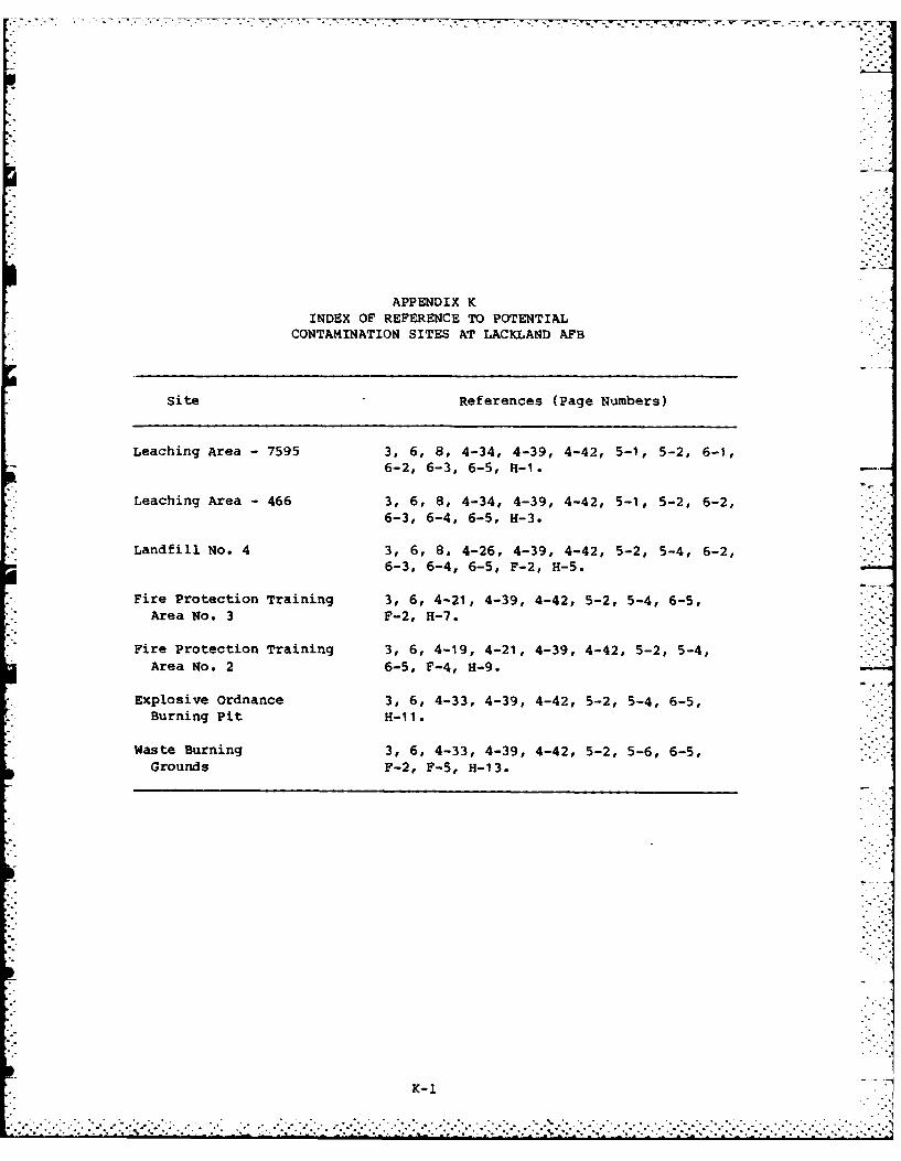
APPENDIX KINDEX OF REFERENCE TO POTENTIAL
CONTAMINATION SITES AT LACKLAND AFB
Site References (Page Numbers)
Leaching Area -7595 3, 6, 8, 4-34, 4-39, 4-42, 5-1, 5-2, 6-1,6-2, 6-3, 6-5, H-i.
*Leaching Area -466 3, 6, 8, 4-34, 4-39, 4-42, 5-1, 5-2, 6-2,6-3, 6-4, 6-5, H-3.
*Landfill No. 4 3, 6, 8, 4-26, 4-39, 4-42, 5-2, 5-4, 6-2,6-3, 6-4, 6-5, F-2, H-5.
*Fire Protection Training 3, 6, 4-21, 4-39, 4-42, 5-2, 5-4, 6-5,Area No. 3 F-2, H-7.
*Fire Protection Training 3, 6, 4-19, 4-21, 4-39, 4-42, 5-2, 5-4,Area No. 2 6-5, F-4, H-9.
Explosive ordnance 3, 6, 4-33, 4-39, 4-42, 5-2, 5-4, 6-5,Burning Pit H-11.
Waste Burning 3, 6, 4-33, 4-39, 4-42, 5-2, 5-6, 6-5,Grounds F-2, F-5, H-13.
K-1