Aerostructures Research at NASA Armstrong Flight Research ... · Aerostructures Research at NASA...
49
Aerostructures Research at NASA Armstrong Flight Research Center Eric Miller NASA Armstrong Flight Research Center Edwards, California, 93523 Aerostructures Branch December 7 th 2015 https://ntrs.nasa.gov/search.jsp?R=20160000438 2018-08-20T23:06:47+00:00Z
Transcript of Aerostructures Research at NASA Armstrong Flight Research ... · Aerostructures Research at NASA...

Aerostructures Research at NASA Armstrong Flight
Research CenterEric Miller
NASA Armstrong Flight Research Center
Edwards, California, 93523
Aerostructures Branch
December 7th 2015
https://ntrs.nasa.gov/search.jsp?R=20160000438 2018-08-20T23:06:47+00:00Z
Outline• NASA Overview
• NACA and NASA• Armstrong Overview• Aerostructures Branch
• Armstrong Projects• NASA Mission Directorates• Aeronautics • Science• Space
• Research Interests• Innovative Structures and Sensors• Loads Monitoring• Shape Sensing
• Finite Element Methods for Shape Sensing
• Conclusions
12/9/2015 Armstrong Flight Research Center 2

NACA to NASA 1915-2015
12/9/2015 Armstrong Flight Research Center 3

NASA Centers
12/9/2015 Armstrong Flight Research Center 4

Neil A. Armstrong
Mystery creates wonder and wonder is the
basis of man’s desire to understand.Neil A. Armstrong
12/9/2015 Armstrong Flight Research Center 5

The purpose of
flight research is
“… to separate
the real from the
imagined and
to make known the
overlooked and the
unexpected.”
— Dr. Hugh L. Dryden
Administrator of NACA (1949-1958)
First Deputy Administrator
of NASA (1958-1965)
12/9/2015 Armstrong Flight Research Center 6
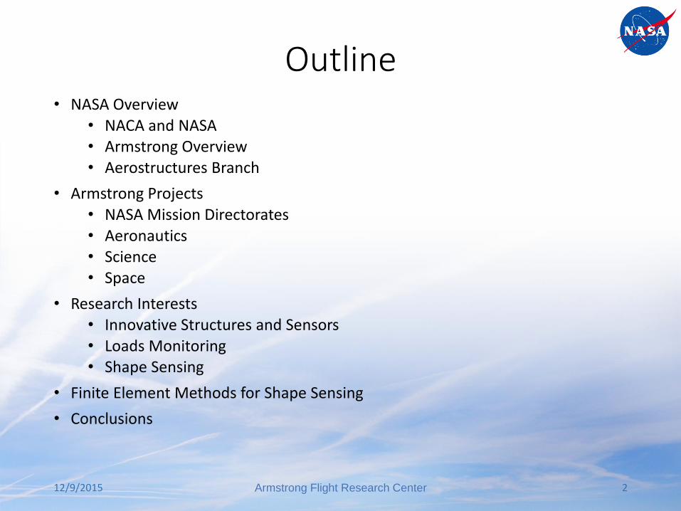
Vision: To separate the real from the imagined through flight
12/9/2015 Armstrong Flight Research Center 7
X-1
F-8
Lunar
Landing
Research
Vehicle
Space Shuttle
Approach and
Landing Tests
M2-F1
X-29
X-43
Helios
X-15

Armstrong Flight Research Center (AFRC)• Edwards AFB
• Remote location
• Varied topography
• 350 testable days per year
• Extensive range airspace
• 29,000 feet of concrete runways
• 68 miles of lakebed runways
• 301,000 acres
• Supersonic corridor
12/9/2015 Armstrong Flight Research Center 8
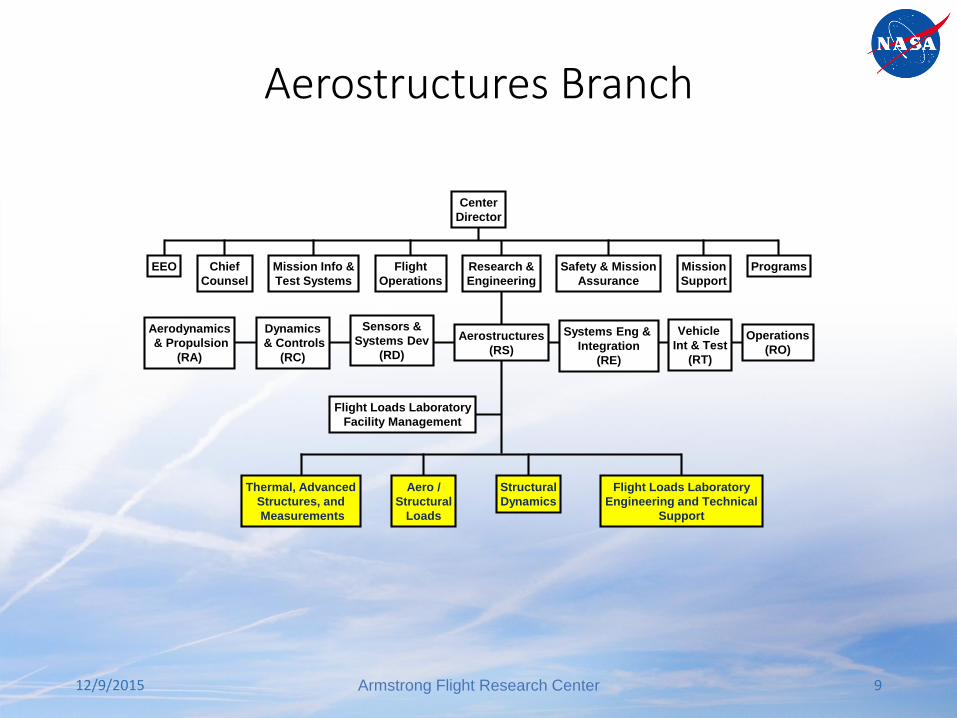
Aerostructures Branch
12/9/2015 Armstrong Flight Research Center 9
Aerostructures
(RS)
Thermal, Advanced
Structures, and
Measurements
Aero /
Structural
Loads
Structural
Dynamics
Flight Loads Laboratory
Engineering and Technical
Support
Flight Loads Laboratory
Facility Management
Center
Director
EEO Chief
Counsel
Mission Info &
Test Systems
Flight
Operations
Safety & Mission
Assurance
Mission
Support
ProgramsResearch &
Engineering
Operations
(RO)
Aerodynamics
& Propulsion
(RA)
Dynamics
& Controls
(RC)
Sensors &
Systems Dev
(RD)
Vehicle
Int & Test
(RT)
Systems Eng &
Integration
(RE)
NASA Armstrong Flight Loads Lab
12/9/2015 Armstrong Flight Research Center 10

Test Capabilities
• Proof loading, load
calibrations, control surface
proof of operations, loads
flight test
• Modal test, flutter flight test,
ASE test, freeplay test, MOI
test
• Thermal and thermal-mechanical test, TPS development and test, pyrometry, SMAs, elastomer aerospace applications, frangible joint evaluations
• Conventional, high temperature, and advanced instrumentation (e.g. FOSS)
Flight Loads Laboratory (FLL)• Airworthiness
• Research
12/9/2015 Armstrong Flight Research Center 11
Aerostructures• Airworthiness
• Loads: External loads; Inertial loads; Store loads; Structural deflections; FEA; Stress analysis; Airframe modification evaluation; Structural design; Loads calibrations; Proof load testing; Functional testing under load; Thermal/mechanical instrumentation; Flight-test support; Envelope expansion
• Dynamics: Modal analysis; Flutter analysis; Ground Vibration Testing (GVT); FEM model tuning; Mass property testing; Structural mode Interaction (SMI) or Structural Coupling Test (SCT); Dynamics and flutter flight-test support; Envelope expansion
• Thermal, Advanced Structures, and Measurements: Heat transfer; Thermal stress; Thermal protection systems/methods; Instrumentation application/installation
• FLL: Ground test execution; Test design; Non-Destructive Evaluation (NDE); Instrumentation; Component calibration
12/9/2015 Armstrong Flight Research Center 12

JPL’s UAVSAR equipped C-20A (GIII)
Stratospheric Observatoryfor Infrared Astronomy
(SOFIA)
Ikhana MQ-9Predator B
Science/ResearchPlatform
Global Hawk RQ-4 Science Platform
ER-2 SciencePlatform
DC-8 Science Platform
F-15A/D
F/A-18
Airworthiness
12/9/2015 Armstrong Flight Research Center 13

Aerostructures• Research
• Loads: Loads calibration techniques; Fiber Optic Strain Sensing (FOSS) applications; Testing of advanced structural concepts; Aero-tow
• Dynamics: GVT methods; MOI methods; Improved flutter flight-test techniques; Multidisciplinary Design, Analysis, and Optimization (MDAO) tool development; Passive/active control analysis/design of flexible structures (multi-discipline); Operational Modal Analysis (OMA); Aeroservoelastic (ASE) systems modeling, analyses, and tool development; Elevated-temperature modal test and analysis
• Thermal, Advanced Structures, and Measurements: Hot structures test techniques; Hot structures design; Thermal coatings; Thermal protection system (TPS) development; Pyrometry; Shape memory allows (SMAs) for aerospace applications; Elastomer aerospace applications; Frangible joint evaluations (NESC); Instrumentation application; FOSS applications; Non-contact strain and temperature measurement; High temperature instrumentation development; Composites M&P
• FLL: Thermal/mechanical testing and analysis
12/9/2015 Armstrong Flight Research Center 14

NASA Armstrong Projects

NASA Mission Directorates
12/9/2015 Armstrong Flight Research Center 16
Science Mission Directorate
(SMD)
Aeronautics Research Mission
Directorate (ARMD)
Human Exploration & Operations
Mission Directorate (HEOMD)
Space Technology Mission
Directorate (STMD)

Aeronautics
12/9/2015 Armstrong Flight Research Center 17
GIII SCRAT Testbed
X-48
F-18
F-15 Testbed
X-56 MUTT

X-48C Hybrid Wing Body (HWB) • Quiet and fuel-efficient technology demonstrator
• Evaluate the low-speed stability and control for a “low-noise” version of the HWB
• Develop control system strategies, including limiters, for robust and safe prototype control system for future commercial aircraft
• Conduct flight experiments with the HWB 8.5% dynamically scaled model
• Final flight (30 flights completed) was April 9, 2013
12/9/2015 Armstrong Flight Research Center 18

X-56A Multi-Utility Technology Testbed (MUTT)
• X-56A MUTT is used to explore integrated structural control of extremely lightweight flexible aircraft
• Partnership: NASA, AFRL, and LM
• Performance Benefits: Active control of flexible wings = weight reduction = fuel savings
12/9/2015 Armstrong Flight Research Center 19
Adaptive Compliant Trailing Edge (ACTE)
12/9/2015 Armstrong Flight Research Center 20

ACTE Project Overview• Project objective: Flight demonstrate a compliant structure that replaces a large
control surface
• Partnership between: NASA, AFRL, and FlexSys Inc.
• ACTE potential performance benefits:
• Cruise drag reduction, wing weight reduction through structural load alleviation, and noise reduction during approach & landing
• Status:
• Phase 1 complete: -2 to 30 deg deflection; flight envelope to 0.75, 40kft, 340 KCAS, 2g load factor
• Phase 2 test planning: Mach expansion to 0.85; Flap twist for load/cruise performance tailoring; Drag characterization; Noise characterization
12/9/2015 21Armstrong Flight Research Center

Historical Perspective: Mission Adaptive Wing
• Mission Adaptive Wing was a joint USAF/NASA/Boeing demonstration program
• Variable camber leading and trailing edge surfaces were installed on a F-111 testbed using mechanical rigid linkages
• The AFTI/F-111 MAW system had 59 flights from 1985 through 1988
• The flight test data showed a drag reduction of around 7 percent at the wing design cruise point to over 20 percent at an off-design condition
• Mechanical actuation system weight penalties and system complexity hindered the acceptance of the technology
12/9/2015 22Armstrong Flight Research Center

Compliant Mechanisms Overview• Compliant design embraces elasticity, rather than avoiding it, to create one-
piece kinematic machines, or joint-less mechanisms, that are strong and flexible (for shape adaptation)
• Large deformations can be achieved by subjecting every section of the material to contribute equally to the (shape morphing) objective while all components share the loads
• Every section of the material undergoes only very small linear elastic strain with very low stress and hence the structure can undergo large deformations with high fatigue life
12/9/2015 23Armstrong Flight Research Center

ACTE Airworthiness • New structure designs required tailoring center processes for clearing the
structure for flight
• Analysis, ground testing, and health monitoring techniques were all utilized
12/9/2015 Armstrong Flight Research Center 24
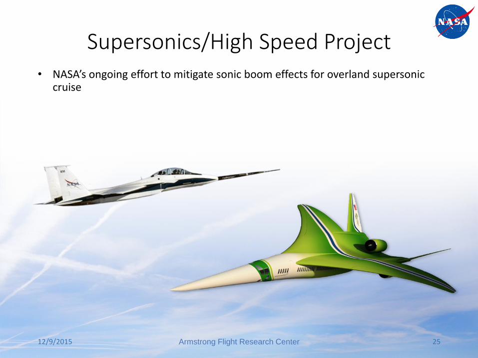
Supersonics/High Speed Project• NASA’s ongoing effort to mitigate sonic boom effects for overland supersonic
cruise
12/9/2015 Armstrong Flight Research Center 25

Science
12/9/2015 Armstrong Flight Research Center 26
Global Hawk
DC-8
C-20A (G-III)
ER-2
Ikhana Predator B

Stratospheric Observatory for Infrared Astronomy
• SOFIA’s 2.5-meter primary mirror, telescope weighs 44,000 pounds
• Missions fly at 43,000 feet to get above 99% of the Earth’s water vapor, which blocks much of the infrared radiation from reaching the ground
• SOFIA can deploy around the world to observe transient events or gain better astronomical visibility.
12/9/2015 Armstrong Flight Research Center 27
Mission Control and
Science Operations Section
Science
Instrument
Telescope
2.5 meter
Education and
Public Outreach
Section
Cavity
Environmental
Control System
Open Port
Telescope Cavity
Pressure
Bulkhead

Space Technology• Armstrong partners with private industry, NASA Centers, and other government
organizations to advance space technology
• Utilizes aircraft platforms to prove technologies
• Develops unique systems to lower the cost to access space
12/9/2015 Armstrong Flight Research Center 28

Aerostructures Research

Innovative Structures and Sensors• Compliant mechanisms
• Materials capable of large deformations
• Shape memory alloys
12/9/2015 Armstrong Flight Research Center 30
HIADHypersonicAerodynamicInflatableDecelerator
ACTE Compliant Mechanisms
Liquid Metal Strain Gage
SMA Actuator

Loads Monitoring• Wing load monitoring and analysis
• Force balance load measurement
12/9/2015 Armstrong Flight Research Center 31

Structural Shape Sensing
12/9/2015 Armstrong Flight Research Center 32
Helios Wing In-flight breakup
Need: to monitor inflight deformation
Solution: vision systems
Solution: sensors for measuring deflection
Finite Element Methods for Shape Sensing

Background• Shape sensing is an active area of research at NASA AFRC
• Multiple shape sensing methods are available such as beam bending approximations and finite element methods
• Alex Tessler has developed the Inverse Finite Element Method (iFEM) for plate and shell three node elements at NASA Langley over the past 10 years
• Eric Miller and Melissa Barnett (summer student) in 2012 implemented a 1-D element in Matlab to investigate the usefulness of this method for upcoming AFRC flight test projects
12/9/2015 Armstrong Flight Research Center 34

Beam Approximation Shape-Sensing Analysis
• 1-D integration of classical beam Eqs for cantilevered, non-uniform cross-section beams (no shear deformation)
• Piecewise linear approximation of strain and taper between regularly spaced “nodes” where strains are measured
• Neutral axis is computed from detailed FEM (SPAR code) or upper and lower strain measurements
• Incorporates cross-sectional geometry of a wing in a beam-type approximation
• Shown to work well for high aspect ratio wings
12/9/2015 35
Method for Real-Time Structure Shape-Sensing, U.S. Patent No. 7,520,176, issued April 21, 2009.
, ,( ( , ) )
( )
[ , ]
x
xx x xw u x z z w
c x
z c c
Armstrong Flight Research Center
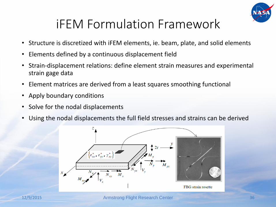
iFEM Formulation Framework• Structure is discretized with iFEM elements, ie. beam, plate, and solid elements
• Elements defined by a continuous displacement field
• Strain-displacement relations: define element strain measures and experimental strain gage data
• Element matrices are derived from a least squares smoothing functional
• Apply boundary conditions
• Solve for the nodal displacements
• Using the nodal displacements the full field stresses and strains can be derived
12/9/2015 Armstrong Flight Research Center 36
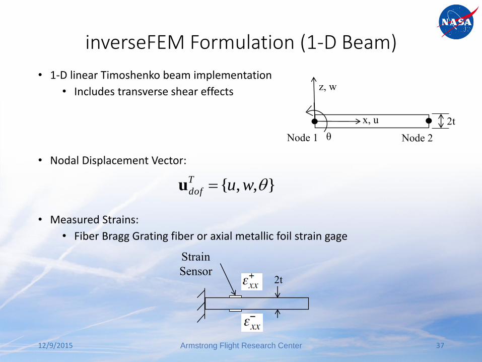
inverseFEM Formulation (1-D Beam)
• 1-D linear Timoshenko beam implementation
• Includes transverse shear effects
• Nodal Displacement Vector:
• Measured Strains:
• Fiber Bragg Grating fiber or axial metallic foil strain gage
12/9/2015 Armstrong Flight Research Center 37
z, w
x, u
θ
2t
Node 1 Node 2
Strain
Sensor2t
},,{ wuT
dof u

Strain Displacement Relation (1-D Beam)
• Nodal Displacement Vector:
• Strain Displacement Relation:
• Beam Strain Measures:• Normal Strains
• Curvature (Bending) Strains
12/9/2015 Armstrong Flight Research Center 38
},,{ wuT
dof u
xxxx z
Where z denotes the total beam thickness (2t)
dof
N
x w
u
xuB00
,,
dof
B
x w
u
xuB00
,,
dof
S
x w
u
xuB10
,,
• Transverse Shear Strain

Experimental Strains (1-D Beam)
• Strain displacement relation in terms of experimentally measured strains
12/9/2015 39
Strain
Sensor2t
where: z=±t, total beam thickness of 2texp denotes experimental strains
expexpexp
xxxx z
)(
)(
exp
exp
xxxxx
xxxxx
t
2
1
2
1
exp
x Cannot be obtained from surface strains
Armstrong Flight Research Center

Weighted Least Squares FunctionalA weighted least-squares smoothing functional in terms of the unknown nodal displacement degrees of freedom
where the squared norms are
n number of strain sensors located within an element
we wk wg weighting constants or penalty parameters associated with individual strain parameters
222
uuuuexpexpexp
)()()()( x
h
xgx
h
xkx
h
xe
h
e www
dxn L
n
i
xii
h
xx
h
x
2
1
2
u1
u
expexp
)()(
dxn
t
L
n
i
xii
h
xx
h
x
2
1
22
u2
u
expexp
)()(
)(
dxn L
n
i
xii
h
xx
h
x
2
1
2
u1
u
expexp
)()(
12/9/2015 Armstrong Flight Research Center 40

inverseFEM Formulation• Minimize the functional with respect to nodal degrees of freedom
• Linear equations:
• Nodal Coordinates
• Element Connectivity
• Boundary Conditions
• Element Strains
• Solve for nodal displacements
0uu 1
)(N
e
h
e
dof
fKu dof
K Symmetric, positive definite matrixudof Nodal Displacement Vectorf (εexp) RHS vector in terms of
experimental strain values
12/9/2015 Armstrong Flight Research Center 41

iFEM Implementation Framework
Direct – Finite
Element Method(Requires: Node
Coordinates, Element
Connectivity and
Geometry, Material
Properties, Boundary
Conditions)
Inverse – Finite
Element Method(Requires: Node
Coordinates, Element
Connectivity and
Geometry, Element
Strains, Boundary
Conditions)
Prescribed
Displacements(Requires: Node
Coordinates, Element
Connectivity and
Geometry, Material
Properties, Boundary
Conditions)
Experimental Strains
from Strain Sensors
Nodal
Displacements,
Stresses and
Strains
Nodal
DisplacementsFull Field Stress
and Strain
12/9/2015 Armstrong Flight Research Center 42
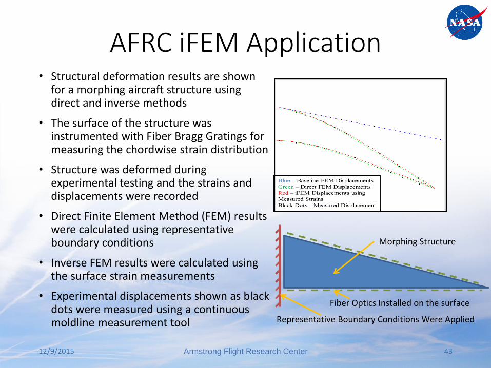
AFRC iFEM Application• Structural deformation results are shown
for a morphing aircraft structure using direct and inverse methods
• The surface of the structure was instrumented with Fiber Bragg Gratings for measuring the chordwise strain distribution
• Structure was deformed during experimental testing and the strains and displacements were recorded
• Direct Finite Element Method (FEM) results were calculated using representative boundary conditions
• Inverse FEM results were calculated using the surface strain measurements
• Experimental displacements shown as black dots were measured using a continuous moldline measurement tool
12/9/2015 Armstrong Flight Research Center 43
Representative Boundary Conditions Were Applied
Fiber Optics Installed on the surface
Morphing Structure

Tip deflection wmax of the beam loaded by a transverse concentrated force Fz at f0=450 Hz.
Shape sensing of 3D frame structures
12/9/2015 Armstrong Flight Research Center 44
Three-dimensional frame structure problem
Marco Gherlone, Priscilla Cerracchio, Massimiliano Mattone, Marco Di
Sciuva, Alexander Tessler

Benefits of iFEM
• Architecture uses standard FEM
• Superior accuracy on coarse meshes (advantage of integration)
• Beam, frame, plate, shell and built-up structures
• Use of partial strain data (over part of structure, or incomplete strain tensor
data)
• Strain-displacement relations fulfilled
• Least-squares compatibility with measured strain data
• Independent of material properties
• Geometrically linear and nonlinear response
• Dynamic regime
• Composite and sandwich structures
12/9/2015 Armstrong Flight Research Center 45

Conclusions• Exciting time to be a structures engineer
• Innovative structures, sensors, and analysis techniques are being developed
12/9/2015 Armstrong Flight Research Center 46

Publications• Miller, E. J., Lokos, W. A., Cruz, J., Crampton, G., Stephens, C. A., Kota, S., Ervin, G., and
Flick, P., “Approach for Structurally Clearing an Adaptive Compliant Trailing Edge Flap for Flight,” 46th Society of Flight Test Engineers (SFTE) International Symposium, Lancaster, California, 2015.
• Sridhar, K., Osborn, R., Ervin, G., Dragan, M., Flick, P., and Paul, D., “Mission Adaptive Compliant Wing – Design, Fabrication and Flight Test,” Symposium on Morphing Vehicles, RTO-MP-AVT-168, Lisbon, Portugal, 2009, p. 18-1.
• Kota, S., “Shape-Shifting Things to Come,” Scientific American, Vol. 310, No. 5, pp. 58-65, May 2014.
• Jenkins, J. M., and DeAngelis, V. M., “A Summary of Numerous Strain-Gage Load Calibrations on Aircraft Wings and Tails in a Technological Format,” NASA TM-4804, 1997.
• Ko, W.L., and Tran, V.T., Further Development of Ko Displacement Theory for Deformed Shape Predictions of Nonuniform Aerospace Structures, NASA/TP-2009-214643, 2009.
• Jutte, C.V., Ko, W.L., Stephens, C.A., Bakalyar, J.A., Richards, W.L., and Parker, A.R., Deformed Shape Calculation of a Full-Scale Wing Using Fiber Optic Strain Data from a Ground Loads Test. NASA/TP-2011-215975, 2011.
12/9/2015 47Armstrong Flight Research Center

Publications• Tessler, A. and Spangler, J. L.: A Variational Principle for Reconstruction of Elastic
Deformations in Shear Deformable Plates and Shells. NASA/TM-2003-212445 (2003).
• Tessler, A. and Spangler, J. L.: Inverse FEM for Full-Field Reconstruction of Elastic Deformations in Shear Deformable Plates and Shells. NASA/TM-2004-090744 (2004).
• Tessler, A. and Spangler, J. L.: A Least-Squares Variational Method for Full-Field Reconstruction of Elastic Deformations in Shear-Deformable Plates and Shells. Computer. Methods Appl. Mech. Engrg. Vol. 194, 327-329 (2005).
• Tessler A.: Structural analysis methods for structural health management of future aerospace vehicles. NASA/TM-2007-214871 (2007).
• M. Gherlone, P. Cerracchio, M. Mattone, M. Di Sciuva, and A. Tessler. Shape sensing of 3D frame structures using an inverse Finite Element Method , International Journal of Solids and Structures, v. 49(22), pp. 3100-3112, 2012.
12/9/2015 48Armstrong Flight Research Center
12/9/2015 Armstrong Flight Research Center 49