Aeroservoelastic and structural dynamics research ... - … · Aeroservoelastic and structural...
10
Aeroservoelastic and structural dynamics research on smart structures conducted at NASA Langley Research Center Anna-Maria %vas McGowan, W. Keats Wilkie, Robert W. Moses, Renee C. Lake, Jennifer Pinkerton Florance, Carol D. Wieseman, Mercedes C. Reaves, Barmac K. Taleghani, Paul H. Mirick, and Matthew L. Wilbur Aeroelasticity and Structural Dynamics Branches NASA Langley Research Center Hampton, Virginia ABSTRACT An overview of smart structures research currently underway at the NASA Langley Research Center in the areas of aeroservoelasticity and structural dynamics is presented. Analytical and experimental results, plans, potential technology pay-offs, and challenges are discussed. The goal of this research is to develop the enabling technologies to actively and passively control aircraft and rotorcraft vibration and loads using smart devices. These enabling technologies and related research efforts include developing experimentally-validated finite element and aeroservoelastic modeling techniques; conducting bench experimental tests to assess feasibility and understand system trade-offs; and conducting large-scale wind- tunnel tests to demonstrate system performance. The key aeroservoelastic applications of this research include: active twist control of rotor blades using interdigitated electrode piezoelectric composites and active control of flutter, and gust and buffeting responses using discrete piezoelectric patches. In addition, NASA Langley is an active participant in the DARPA/ Air Force Research Laboratory/ NASA/ Northrop Grumman Smart Wing program which is assessing aerodynamic performance benefits using smart materials. Keywords: aeroelasticity, smart structures, piezoelectric actuators, active fiber composites, rotorcraft, buffet load alleviation, individual blade control, aeroservoelasticity, shape memory alloys, damping augmentation, piezoelectric power consumption 1. INTRODUCTION The Aircraft Morphing program’ at the NASA Langley Research Center is a new 6-year program to develop smart devices for airframe applications to enable self-adaptive flight for a revolutionary improvement in efficiency and safety. In this context, a smart device is one that senses and reacts to its local environment to achieve some overall system benefit such as an increase in performance or maintaining flightworthiness in the event of other failures. The goals of the Aircraft Morphing program are to develop and mature smart devices and the enabling technologies needed to embed these devices in aircraft structures (and thus create an “active component”) and efficiently use them to provide cost-effective system benefits. Research in the Aircraft Morphing program covers a wide range of disciplines and supports the integrated program focus areas of active aerodynamics, active noise control and active aeroelastic control. This paper presents an overview of the current research conducted in the areas of active aeroelastic control and the related structural dynamics research activities conducted in the Aircraft Morphing program as well as other Langley programs. A review of previous smart structures-based aeroservoelastic research activities at NASA Langley is also presented. The goals of applying smart devices to aeroelastic problems are to control the aerodynamic andor structural characteristics of air vehicles to improve flutter characteristics and reduce gust, buffeting and maneuver loads of fixed-wing vehicles and to reduce dynamic responses and loads on rotorcraft. These benefits also result in reduced emissions and increased performance and safety. In many cases, applications of smart devices will take advantage of the inherent flexibility in air vehicles to create more efficient structural designs. At NASA Langley, much of the effort in the area of controlling dynamic aeroelastic phenomena is focused towards applying piezoelectric-based actuators for active strain actuation because of their high bandwidth, the wealth of knowledge available on piezoelectrics and previous experience with piezoelectric-based devices. Research using other smart materials is being conducted in the Smart Wing program in collaboration with the Defense Advanced Research Projects Agency (DARPA), the Air Force Research Laboratories (AFRL), and the Northrop Grumman Corporation. In this program, shape memory alloys, Terfenol-D, and piezoelectric actuators are being used for wing shape control for improved aerodynamic and aeroelastic performance. The use of piezoelectric materials and other smart materials for structural vibration control using active strain actuation has been intensely studied since the early 1980’s. Active strain actuation typically refers to dynamically or statically straining Further author information: Email: [email protected], Telephone: 757-864-2846, Fax: 757-864-8678, Mailing Address: Mail Stop 340, NASA Langley Research Center, Hampton, VA 2368 1-2 I99 https://ntrs.nasa.gov/search.jsp?R=20040110282 2018-06-17T19:59:57+00:00Z
Transcript of Aeroservoelastic and structural dynamics research ... - … · Aeroservoelastic and structural...

Aeroservoelastic and structural dynamics research on smart structures conducted at NASA Langley Research Center
Anna-Maria %vas McGowan, W. Keats Wilkie, Robert W. Moses, Renee C. Lake, Jennifer Pinkerton Florance, Carol D. Wieseman, Mercedes C. Reaves, Barmac K. Taleghani,
Paul H. Mirick, and Matthew L. Wilbur
Aeroelasticity and Structural Dynamics Branches NASA Langley Research Center
Hampton, Virginia
ABSTRACT An overview of smart structures research currently underway at the NASA Langley Research Center in the areas of aeroservoelasticity and structural dynamics is presented. Analytical and experimental results, plans, potential technology pay-offs, and challenges are discussed. The goal of this research is to develop the enabling technologies to actively and passively control aircraft and rotorcraft vibration and loads using smart devices. These enabling technologies and related research efforts include developing experimentally-validated finite element and aeroservoelastic modeling techniques; conducting bench experimental tests to assess feasibility and understand system trade-offs; and conducting large-scale wind- tunnel tests to demonstrate system performance. The key aeroservoelastic applications of this research include: active twist control of rotor blades using interdigitated electrode piezoelectric composites and active control of flutter, and gust and buffeting responses using discrete piezoelectric patches. In addition, NASA Langley is an active participant in the DARPA/ Air Force Research Laboratory/ NASA/ Northrop Grumman Smart Wing program which is assessing aerodynamic performance benefits using smart materials.
Keywords: aeroelasticity, smart structures, piezoelectric actuators, active fiber composites, rotorcraft, buffet load alleviation, individual blade control, aeroservoelasticity, shape memory alloys, damping augmentation, piezoelectric power consumption
1. INTRODUCTION The Aircraft Morphing program’ at the NASA Langley Research Center is a new 6-year program to develop smart devices for airframe applications to enable self-adaptive flight for a revolutionary improvement in efficiency and safety. In this context, a smart device is one that senses and reacts to its local environment to achieve some overall system benefit such as an increase in performance or maintaining flightworthiness in the event of other failures. The goals of the Aircraft Morphing program are to develop and mature smart devices and the enabling technologies needed to embed these devices in aircraft structures (and thus create an “active component”) and efficiently use them to provide cost-effective system benefits. Research in the Aircraft Morphing program covers a wide range of disciplines and supports the integrated program focus areas of active aerodynamics, active noise control and active aeroelastic control. This paper presents an overview of the current research conducted in the areas of active aeroelastic control and the related structural dynamics research activities conducted in the Aircraft Morphing program as well as other Langley programs. A review of previous smart structures-based aeroservoelastic research activities at NASA Langley is also presented.
The goals of applying smart devices to aeroelastic problems are to control the aerodynamic andor structural characteristics of air vehicles to improve flutter characteristics and reduce gust, buffeting and maneuver loads of fixed-wing vehicles and to reduce dynamic responses and loads on rotorcraft. These benefits also result in reduced emissions and increased performance and safety. In many cases, applications of smart devices will take advantage of the inherent flexibility in air vehicles to create more efficient structural designs. At NASA Langley, much of the effort in the area of controlling dynamic aeroelastic phenomena is focused towards applying piezoelectric-based actuators for active strain actuation because of their high bandwidth, the wealth of knowledge available on piezoelectrics and previous experience with piezoelectric-based devices. Research using other smart materials is being conducted in the Smart Wing program in collaboration with the Defense Advanced Research Projects Agency (DARPA), the Air Force Research Laboratories (AFRL), and the Northrop Grumman Corporation. In this program, shape memory alloys, Terfenol-D, and piezoelectric actuators are being used for wing shape control for improved aerodynamic and aeroelastic performance.
The use of piezoelectric materials and other smart materials for structural vibration control using active strain actuation has been intensely studied since the early 1980’s. Active strain actuation typically refers to dynamically or statically straining
Further author information: Email: [email protected], Telephone: 757-864-2846, Fax: 757-864-8678, Mailing Address: Mail Stop 340, NASA Langley Research Center, Hampton, VA 2368 1-2 I99
https://ntrs.nasa.gov/search.jsp?R=20040110282 2018-06-17T19:59:57+00:00Z

(bending or twisting) a structure to achieve control. With a bandwidth of approximately 20 KHz, piezoelectric materials have been the materials of choice for applications requiring high bandwidth, such as aeroelasticity and acoustics. In addition, since a very thin layer of piezoelectric materials can be surface-bonded to or embedded within a structure, these materials can be nonintrusive and very effective structural controllers. For active strain actuation, in-plane actuation of patch-like piezoelectric actuators is often used. Another promising emerging technology for active strain actuation is the use of interdigitated electrode piezoelectric fibers woven into a composite laminate, The key benefits of using piezoelectric actuators for aeroelastic control versus conventional control surfaces are: increased control bandwidth, mechanical simplicity, lack of control lag, control of localized areas subject to vibratory or fatigue problems, and the nonintrusive nature of flat piezoelectric actuators. The key drawbacks are potentially low control authority in some cases and the additional hardware required to power piezoelectrics. Also, the control authority of piezoelectric actuators is independent of aerodynamic forces, which can be a benefit or a drawback depending on the application.
NASA Langley has been actively investigating the control of aeroelastic response using advanced concepts such as smart devices for many years. Current research activities at NASA Langley are primarily motivated by the successes of the previous efforts and the many issues raised by these studies and additional research conducted by several others in the field. Previous smart fixed-wing aeroelastic research efforts conducted at NASA Langley are summarized in reference 2. Some of these efforts are briefly reviewed in the current document to highlight key issues and discuss several related follow-on research activities. In general, the research approach is primarily focused in three key areas: 1) developing experimentally-validated structural and aeroservoelastic modeling techniques; 2) conducting analytical and bench experimental tests to assess feasibility and understand system trade-offs; and 3) conducting large-scale wind-tunnel tests to demonstrate system performance.
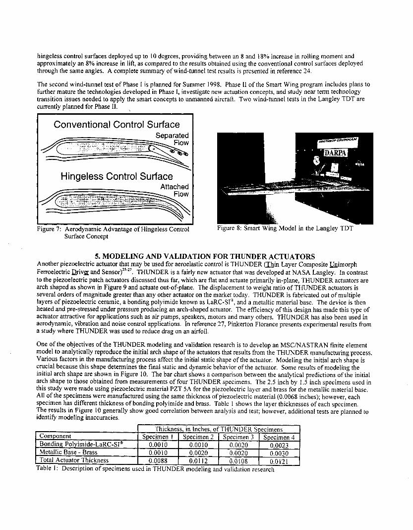
Investigations on applying smart devices to both fixed-wing vehicles and rotorcraft are presented herein. Presented first is research on developing and validating analytical methods and conducting bench tests on models where piezoelectric patch actuators are used for control. Then studies on applying patch piezoelectric actuators to suppress tail buffeting are discussed. A summary of the DARPAI AFRL/ NASA/ Northrop Grumman Smart Wing program is given next followed by a discussion of research on a relatively new actuator called THUNDER. An overview of future research on fixed-wing aeroelasticity is also presented. Lastly, a discussion of active piezoelectric fiber composites and how they are being used in NASA Langley’s Active Twist Rotor program is presented.
2. ANALYSIS AND BENCH TESTS USING PATCH PIEZOELECTRIC ACTUATORS
2.1 Piezoelectric Aeroelastic Response Tailoring Investigation (PARTI) Much of the research at NASA Langley on the development of analytical and experimental methods for patch piezoelectric actuators was motivated by the results and “lessons learned” from a program called the Piezoelectric Aeroelastic Response Tailoring Investigation (PARTI). The PARTI program, which took place from 1991-1996, was a cooperative effort between NASA Langley and the Massachusetts Institute of Technology3. This program was an analytical and experimental study using a relatively large, multi-degree-of-freedom aeroelastic testbed. The objectives were to demonstrate the ability of strain- actuated adaptive wings to control aeroelastic phenomena, including wing flutter suppression and gust load alleviation, and to develop experimental and analytical techniques. To accomplish these objectives, a wind-tunnel model was designed and fabricated, aeroservoelastic analyses were performed, and the model was ground and wind-tunnel tested in NASA Langley’s Transonic Dynamics Tunnel (TDT)4. During the program, active flutter suppression and reduced gust loads using piezoelectric actuation on a 4 foot long semi-span wing were successfully demonstrated in wind-tunnel testing. Flutter dynamic pressure was increased 12% and peak wing root bending moment due to gust was reduced by 75%.
Although the model used during the PARTI program was a plate-like model (versus a monocoque structure), the experimental results show clear evidence that piezoelectric technology may provide a viable alternative to conventional aeroelastic control techniques. As a result of this program, an extensive database of experimental information has been gathered that is instrumental in understanding the many issues associated with applying strain actuation technology to dynamic problems. Three issues were identified during the PARTI program as key areas where additional research is needed. These issues (research areas) and the current effort to address these issues are:
Research area: The development of detailed structural and aeroelastic models is needed to promote a better understanding of the local and global effects of piezoelectric actuation. Current activity: Finite element and aeroservoelastic modeling and validation research have both been initiated in the Aircraft Morphing program. Research area: The investigation of piezoelectric power consumption characteristics during active control may enable a more realistic evaluation of the economic viability of using piezoelectric actuators on full-scale vehicles.
I )
2 )

Current activity: Ground tests are planned to investigate the efficiency of active and passive control schemes, using a method for predicting the power consumption of piezoelectric actuators that was developed in a follow-on study to the PARTI program. Research area: The development of improved control and optimization techniques is needed to determine how to efficiently use the piezoelectric capabilities to their hllest extent. Current activity: Thus far, two studies have used data from the PARTI wind-tunnel tests to examine how to optimally use the piezoelectric actuators to control aeroelastic response; and, further research is planned in this area via open and closed-loop ground tests.
3)
2.2 Finite Element Modeling and Validation for Patch Piezoelectric Actuators During the PARTI program, a finite element model of the PARTI wind-tunnel model was created and the natural frequency and mode shape results were validated with ground vibration tests. Although global structural dynamic data (mode shape and natural frequency data) could generally be modeled with sufficient accuracy, local deformation and force data were very difficult to model accurately with reasonable computational efficiency. It was found that considerably small finite element mesh sizes and a judicious use of finite elements were needed to capture the abruptly changing strain field in the area immediately next to the piezoelectric actuators. Thus, the analytical model used during the PARTI program was primarily used for structural design (including actuator and sensor placement) and preliminary control assessments. For final wind- tunnel testing, all control laws were designed using experimental data. Although existing modeling techniques generally yield good theoretical results, they can be complicated and difficult to implement even for simple structures.
The objectives of current research at NASA Langley on finite element modeling and validation on patch piezoelectric actuators are to develop and validate simple and accurate techniques for modeling complex structures containing piezoelectric actuators using commercially-available FEM codes such as MSCMASTRAN. Finite element models of structures of increasing complexity, such as composite plates, box beams, and monocoque sections will be developed and validated. The first modeling technique to be investigated is described in reference 5 . This analytical technique involves reducing a finite element model, which is typically composed of a large number of equations, to a low order modal model that includes the “Ritz” states to improve convergence of low frequency modes. These Ritz states are derived from the static deflection of the structure when piezo-generated forces are applied. Temperature-induced expansion is used to simulate voltage actuation. The first model and testbed will consist of a composite cantilever plate with piezoceramic patches surface-mounted near the root. The design, modeling, fabrication and testing of a composite box beam will follow.
This research will build upon the work of several other researchers who have developed analyses and numerical models to analyze piezoelectrically-controlled structure^^-'^. Some of these studies include: superelement modeling conducted by Hauch6; higher-order theory developed by Seeley’; and finite element modeling with a consideration of damping developed by Freed and Babuska’. These research efforts and many others clearly show that the key considerations in modeling in-plane piezoelectric actuation are capturing the sharply varying strain field around the piezoelectric actuator and modeling damping to more accurately capture the dynamic piezoelectric effect. Furthermore, to model larger, more complex structures with piezoelectric actuators, improved finite element modeling techniques are required. In particular, Seeley’s work (funded under a NASA Langley grant) showed that the strain field in the host structure in the vicinity of the piezoelectric actuator is nonlinear. Most analyses used to model piezoelectric actuation (including the one used during the PARTI program) assume the strain field through the thickness of the host structure is linear. Seeley used higher-order laminate theory, which was implemented using a finite element method, to model the piezoelectric actuation of composite plates. This research indicates that strain measurements (via traditional gages) taken around a piezoelectric actuator may give unexpected results since most researchers assume stress and strain fields are essentially linear.
2.3 Aeroservoelastic Modeling and Validation for Patch Piezoelectric Actuators During the PARTI program, Pototzky” developed a method of modeling the aeroservoelastic response of a structure controlled with piezoelectric actuators. He used a finely-meshed finite element model of a cantilevered beam as his test case. This model did not have aerodynamic data with which to validate the aeroservoelastic results; therefore, this method was validated at air-off conditions only. His method consists of using a thermal mechanical analogy to create a static deflection shape of the host structure actuated by the piezoelectric actuators. This shape is then appended to the free vibration mode shapes and the new augmented modal matrix is then used in an aeroservoelastic analysis using the Interaction of Structures, Aerodynamics and Controls (ISAC)” code. In the aeroservoelastic analysis in ISAC, the appended static deflection shape is used as the control mode. Including this deflection shape as a mode in the aeroelastic analysis may allow for the aerodynamic influence of piezoelectric actuation to be computed. Since aerodynamic data for this test case is not available, this method of modeling the aerodynamic influence of the piezoelectric actuation has not been validated. However, the current research studies, to be discussed later, seek to assess the accuracy of this and other aeroservoelastic modeling techniques. When compared with experimental results at zero airspeed, the transfer function data of acceleration and strain with respect to piezo excitation agreed reasonably well in terms of both magnitude and phase. Also, note that a very finely-
meshed finite element grid was used to ensure the accuracy of strain information. For larger, more complex models than the simple cantilevered beam model used for this test case, this may be computationally difficult.
Pototzky’s method is one of many developed to incorporate piezoelectric actuation in aeroservoelastic Much of this work uses simplified structural models and relies upon limited experimental data. To enable the study of more complex structures and to ensure analytical model accuracy through experimental validation, the objectives of the aeroservoelastic modeling and validation research in the Aircraft Morphing program are to: 1) assess the state-of-the-art in simulating piezoelectric actuation in aeroservoelastic modeling using simple and moderately complex models and 2) in the long term, develop and validate (via wind-tunnel testing) methods that may efficiently be used on larger, more complex structures. For this research, doublet lattice aerodynamics and the ISAC code will be used to perform the aeroservoelastic analyses. Existing data from the PARTI and ACROBAT programs will be used to assist in verifying the analysis methods. Verification of the analysis techniques will first be conducted at zero airspeed and then expanded to correspond to wind-on data. Data from ground modal tests conducted in the Aircraft Morphing program will be used to further verify zero-airspeed characteristics. Additional simplified models may be constructed and ground and wind-tunnel tested to provide more experimental data to compare with the aeroservoelastic modeling development.
2.4 Ground Testing Using Patch Piezoelectric Actuators The research issues identified in the PARTI program include determining piezoelectric power consumption during active control and applying improved control and optimization techniques. Research in both of these areas at NASA Langley is focused toward the long-term goals of developing techniques to control larger, more realistic structures using piezoelectric actuators and assessing the economic viability of using piezoelectric actuators for control by examining power consumption. This research also involves evaluating a variety of control techniques to ascertain the most efficient and/or effective technique for suppressing vibration.
One of the techniques being investigated in the Aircraft Morphing program is damping augmentation using shunted piezoelectric actuators. This method, which uses a parallel inductor and resistor to electrically shunt the piezoelectric actuator, may provide a simple, low power alternative to active control using piezoelectric actuators configured in the conventional, unshunted manner. Future research activities include conducting open- and closed-loop experimental ground tests on large-scale structures to assess trade-offs in piezoelectric control effectiveness, power consumption and optimal control strategies using both active and passive control techniques with shunted piezoelectric actuators and unshunted piezoelectric actuators. For the ground tests, an electrodynamic shaker will be used to provide a disturbance source.
2.4.1 Test Set-up and Approach The existing PARTI wind-tunnel model, a sketch of which is shown in Figure 1, is being used for the ground tests. This model consists of a composite plate in a sandwich construction (graphite epoxy facesheets with an aluminum honeycomb core) with 36 piezoelectric patches surface-bonded to each side of the plate as well as 14 conventional strain gages and 4 accelerometers. The 36 piezoelectric patches are arranged into 15 groups to be used as 15 actuators or sensors or a combination of both. The ground testing involves first identifying the natural kequencies, damping and mode shapes in a modal test of the PARTI model. Next, open-loop data to design the shunt circuit and the active control laws will be obtained. The data required to design the shunt circuit is the voltage output of each piezoelectric patch due to shaker disturbance of the model. This data is then used to determine the size of the inductor and resistor needed in the shunt circuit. For active control law design, the data required is the voltage output of each sensor due to each actuator’s excitation and shaker disturbance. This open-loop frequency response function data is used to build an experiment-based analytical model of the wing using a time domain system identification technique. For active control, the sensors may be either the conventional sensors (strain gages and accelerometers) or the piezoelectric patches. Future testing is also planned for new models being constructed in support of the finite element modeling and validation effort mentioned previously.
The shunted piezoelectric actuator studies will be accomplished in collaboration with Boeing-Huntington Beach. The technique used by Boeing involves using a parallel inductor and resistor circuit, as shown in Figure 2, to electrically shunt the piezoelectric actuators”. This effectively increases the damping of the host structure at a specific frequency and enables vibration amplitudes to be controlled. Additional shunt circuits can be added to a single piezoelectric actuator to add damping to additional modesI6. The parallel electric shunt circuit allows optimal frequency tuning of the circuit to be performed by adjusting the amount of inductance independent of the resistor response. This eliminates the iterative process necessary to tune series shunt circuits. In the shunted arrangement, the inductor can be selectively tuned such that the parallel LC circuit of the inductance and the piezoelectric capacitance becomes anti-resonant at a particular frequency. This anti-resonant condition causes the reactive component of the impedance to become infinite or open-circuited, thereby allowing the resistor within the shunt circuit to dissipate the mechanical energy via Joule heating.

(with group number)
Q I I Strain Gage
Accelerometer 0
Description of Supergroups
Groups Supergroup Piezoelectric Actuator
- A 8,11,12,14,15 - 6 9,10,13
- c 1,2,3,4 - D 5,6,7 -
Figure 1: PARTI Wind-Tunnel Model
Two of the key benefits of using shunted piezoelectric actuators for active (active tuning of the shunt circuit) or passive damping augmentation is the very low power required for operation of the circuit and the simplicity of mechanical operation when the shunted actuators are used passively for control. This is in contrast to one of the main issues with using piezoelectric actuators for active vibration control: the potentially high amount of power needed and the corresponding power supplies and amplifiers required. Some applications, however, may require active control to achieve the desired system performance.
Figure 2: Parallel Shunt Circuit for Passive Vibration Control
2.4.2 Piezoelectric Power Consumption During Active Vibration Control During the ground tests, comparisons and trade-offs between control effectiveness and power consumption of the active control versus active/passive damping control will be performed. To compute piezoelectric power consumption during active vibration control, a method developed in a PARTI follow-on study will be usedi7-'*. For a given control law, the power required by the piezoelectric actuators can be conservatively calculated using:
P(0) G -0 1 V*(W) i C i (v(0)) 2 ; - - I . - a
where P(o) is the power required, w is the circular frequency, V(w) is the voltage of the control law output signal, C,(V(w)) is the effective capacitance of each piezoelectric actuator being used for control, and n is the total number of piezoelectric actuators being used by the control law. Although effective capacitance is often considered a constant quantity as quoted by the actuator manufacturer, measurements made at NASA Langley have shown that the effective capacitance is actually

approximately a linear function of voltage. These capacitance values are best obtained through experimental tests over the bandwidth and voltage range of interest. More discussion of the voltage dependence of piezoelectric capacitance is given in reference 18.
The power expression in the equation was developed through both analysis and experimental tests using a cantilevered beam model with surface-bonded piezoelectric actuators. The tests showed that the maximum power required to control a structure using surface-bonded piezoelectric actuators can be estimated without modeling the complex dynamics between the piezoelectric actuator and the host structure. Experimental results demonstrated that for a perfectly-controlled structure (all motion is stopped), the power consumption of the piezoelectric actuators is a function of the material and geometric properties of the piezoelectric actuators. Furthermore, as control effectiveness decreases, the power consumption of the actuators decreases. Hence, maximum power consumption occurs when the structure is perfectly controlled. Experimental tests further demonstrated that the structural dynamics of the host structure and piezoelectric actuators have a minimal effect on the power consumed by the actuators during active control. Consequently, for typical surface-bonded piezoelectric actuators, the power required for active vibration control can be conservatively determined within 90% accuracy (generally within 97% accuracy) without modeling the complex structural dynamics of the actuator and host ~tructure”~’~.
2.4.3 Choosing Optimal Actuators and Sensors for Active Control Law Design Another important element of controlling large structures using several piezoelectric actuators is the effective use of optimization schemes. For example, wind-tunnel results from the PARTI program showed that at a given tunnel condition, one control law using all 15 actuators reduced gust loads by 75% while another control law used only 6 actuators to reduce gust loads by 72%. For many cases, such a minor loss of control effectiveness (3%) is inconsequential compared to the 60% reduction in the number of actuators required, which reduces weight and complexity. References 19 and 20 describe two optimal control studies conducted using data from the PARTI wind-tunnel tests. Both of these studies investigated optimally choosing a subset of actuators from a set already in place on the model. Placement of the actuators was specified a priori and was not a variable in the optimization studies. As an example, Lim’s studies in reference 19 focused on the selection of a “best” subset of actuators for improving the performance of an active control system at a single design point, namely, the onset of flutter. The formulation of an actuator selection metric, based on the Hankel singular value approach, was examined from a flutter control design perspective such that the degree of participation of the individual structural modes contributing to the flutter condition was used to weight the metric in the feedback loop. Simulation results using Hz and H, control law designs showed that the optimal actuator set gave improved closed-loop performance, independent of the control law design selected.
3. ACTIVE BUFFET LOAD ALLEVIATION
3.1 Actively Controlled Response of Buffet Affected Tails (ACROBAT) program The ACROBAT program*’, which took place from 1994-1997, focused on demonstrating the feasibility of using active controls to alleviate vertical tail buffeting experienced by twin-tail aircraft at high angles of attack. For these aircraft, buffeting of the vertical tails results when vortices, originating at the leading edge extensions, burst ahead of the vertical tails, engulfing the tails in highly turbulent flow. The resulting vibrations are a significant concern from fatigue and maintenance points of views since inspections and repairs are high cost items to military fleets.
Active control using piezoelectric actuators provides a potential solution to the buffeting problem. NASA Langley has partnered with DoD, industry, and international agencies to perform wind-tunnel and ground-vibration tests of buffet load alleviation systems that use smart materials. During the ACROBAT program, a M-scale rigid full-span model of the F/A- 18 aircraft was tested in the Langley Transonic Dynamics Tunnel (TDT) using an active rudder and, separately, using active patch piezoelectric actuators to control buffeting. The arrangement used for the piezoelectric actuators (which were placed as opposing pairs on both surfaces of the vertical tail) is shown in Figure 3. A cover was placed over the actuators during tests to provide a smooth aerodynamic surface. The typical response of the vertical tail in the first bending mode is shown in Figure 4 as a plot of the normalized peak of the power spectral density of root bending moment versus angle of attack. These wind-tunnel tests showed that piezoelectric actuators reduced the power spectral density peak value and the root mean square value of the tail root bending moment by 60% and 19%, respectively. The tests effectively demonstrated that piezoelectric actuators provide a viable means for alleviating buffeting.
A vital part of maturing piezoelectric control technologies so that they may be used on full-scale aircraft in the future is developing an understanding of the issues associated with scaling wind-tunnel test results to full-scale and conducting tests on actual full-scale structures. With this in mind, three research activities in the area of active buffeting alleviation using piezoelectric actuators may provide useful results: ( I ) ground tests ofa full-scale F/A-18 airplane using simulated buffet loads, which were completed in February 1998; (2) additional wind-tunnel tests using scaled models to examine scaling
issues, which are currently planned to begin in late 1998; and (3) potential future flight test demonstrations, which are tentatively scheduled to begin in 200 I .
peak of
moment PSD
root bending 0.5
" the ACROBAT Wind-Tunnel Model
- '1 -
1 .o
Normalized
Program
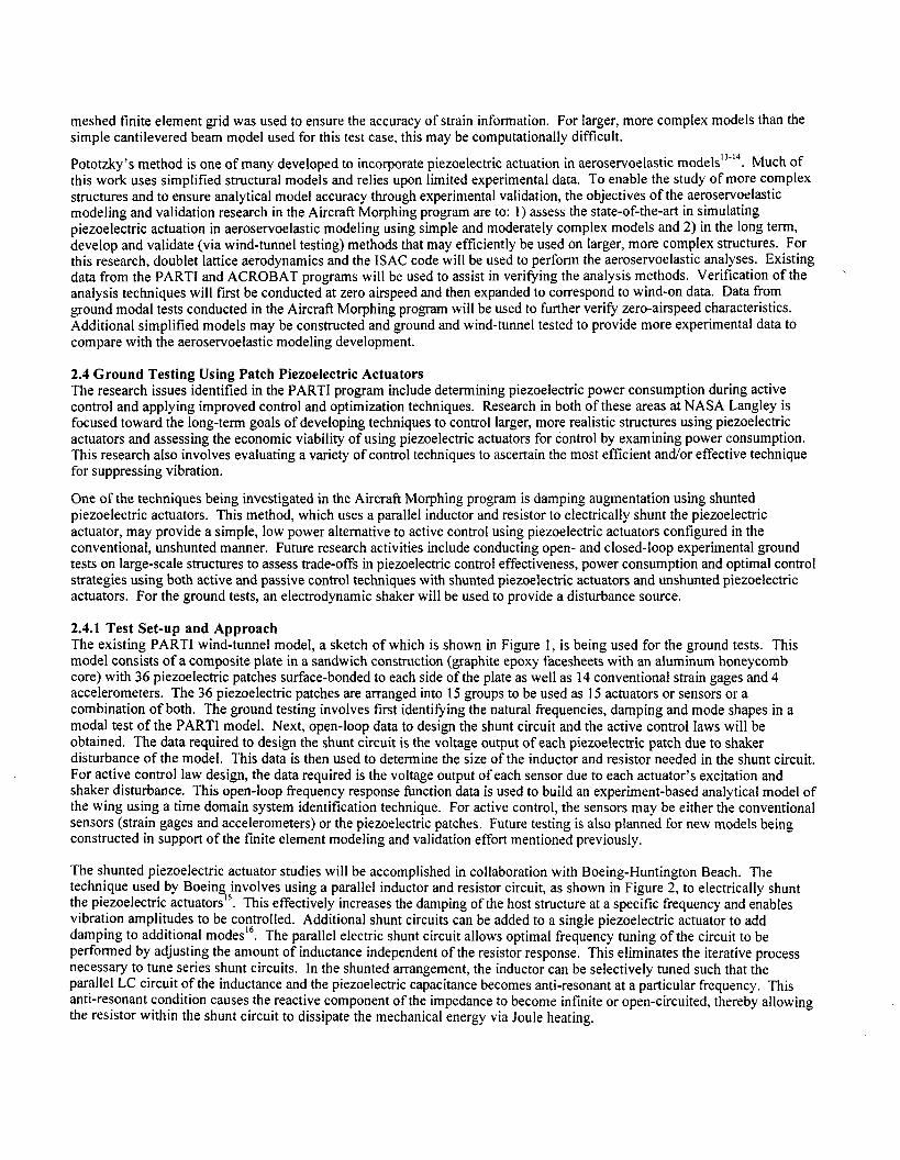
3.2 Ground Testing Using a Full-Scale F/A-18 with Patch Piezoelectric Actuators Ground tests of a full-scale F/A-18 aircraft were conducted under the auspices of The Technical Cooperation Program (TTCP) as well as an international bilateral agreement and involved the USA, Australia, and Canada. The tests were conducted at the Aeronautics and Maritime Research Laboratory (AMRL) in Melbourne, Australia. The test facility used air bags and shakers to simulate buffet loads on the aircraft. Patch piezoelectric actuators were surface-bonded to the vertical tails for active control. The piezoelectric actuators and control system were designed and built by Active Controls !l<perts (ACX) in fulfillment of a Phase I1 SBIR with the Air Force Research Laboratory at Wright Patterson Air Force Base . NASA Langley assisted with control law design and experimental testing.
During the Fall of 1997, a preliminary control law was designed and tested on the F/A-18 that commanded the piezoelectri actuators located on the vertical tail to add damping to the first bending mode during simulated buffet loads. This preliminary control law was very similar to a control law used during the ACROBAT wind-tunnel tests that successhlly added damping by commanding piezoelectric actuators. The purpose of the preliminary control law was to verify that the digital controller being used worked as designed and that full-scale F/A-18 vertical tail buffeting could be alleviated using actively controlled piezoelectric actuators. Figure 5 shows the open- and closed-loop results using this control law at one simulated flight condition. The reduction in the peak response indicated in the figure shows that the preliminary control law worked well to alleviate vertical tail buffeting. Closed-loop data from the ground tests will be used to determine the control effectiveness of piezoelectric actuators over a range of simulated flight conditions and for future scaling studies to be conducted in wind-tunnel tests.
100
10-2
g2/Hz
10-4
10-6 10 20 30
Frequency, Hz ~~ ~ ~~
Figure 5 Power Spectral Density Functions of Acceleration Measured Near the Trailing Edge Tip on the F/A- 18 Aircraft During Ground Testing
3.3 Future Wind-Tunnel and Flight Tests A scaled version of the buffet load alleviation system used in the ground test will be ground- and wind-tunnel tested on a 16% F/A-18 model at the Transonic Dynamics Tunnel in 1999 as part of the SIDEKIC (Scaling Influences Derived from Experimentally-Known Impact of Controls on buffet-affected tails) program. As the acronym implies, relationships for scaling

the performance of piezoelectric actuators will be determined and validated by comparing the full-scale ground test results with scaled ground- and wind-tunnel results. Additionally, plans are underway to measure buffet pressures on other twin-tail configurations, namely the F-22 and the Joint Strike Fighter (JSF).
Plans are also being discussed by the Air Force Research Laboratory, NASA Dryden Flight Center, and NASA Langley for a flight demonstration of active rudder and active piezoelectric actuators in 2001. NASA Langley plans to play an active role in the flight demonstration tests by wind-tunnel testing scaled-models of the proposed buffet load alleviation system concepts prior to the flight tests and by designing control laws for the flight tests.
4. DARPA/ AFRL/ NASA/ NORTHROP GRUMMAN SMART WING PROGRAM The overall objective of the DARPAI AFRL/ NASA/ Northrop Grumman Smart Wing program is to design, develop and demonstrate the use of smart materials and structures to improve the aerodynamic performance of military aircraft including improvements in lift to drag ratio, maneuver capabilities and aeroelastic effects. The approach includes: 1) designing, fabricating and testing scaled semi-span and full-span wind-tunnel models; 2) addressing power, reliability, packaging and system integration issues; and 3) laying the ground work for technology transition in a potential follow-on program. An overview of the program is presented in reference 23. The Smart Wing program is led by the Northrop Grumman Corporation who was awarded DAEWA contracts for Phase I, which began in January 1995, and Phase 11, which began in September 1997. Phase I and Phase I1 contracts are being monitored by the Air Force Research Laboratory (AFEU) at Wright-Patterson Air Force Base. Wind-tunnel testing during the program is being performed at the NASA Langley TDT via a Memorandum of Agreement between NASA Langley and Northrop Grumman. In addition, the administrative responsibilities of the program are being coordinated through an Interagency Agreement between the AFRL and NASA Langley. Other members of the large team of researchers on the program include: Lockheed Martin Astronautics and Control Systems; Naval Research Labs; Mission Research Corporation; Rockwell Science Center; Fiber & Sensor Technologies, Inc.; Etrema Products, Inc.; SRI International; University of California, Los Angeles; Georgia Institute of Technology; and the University of Texas at Arlington.
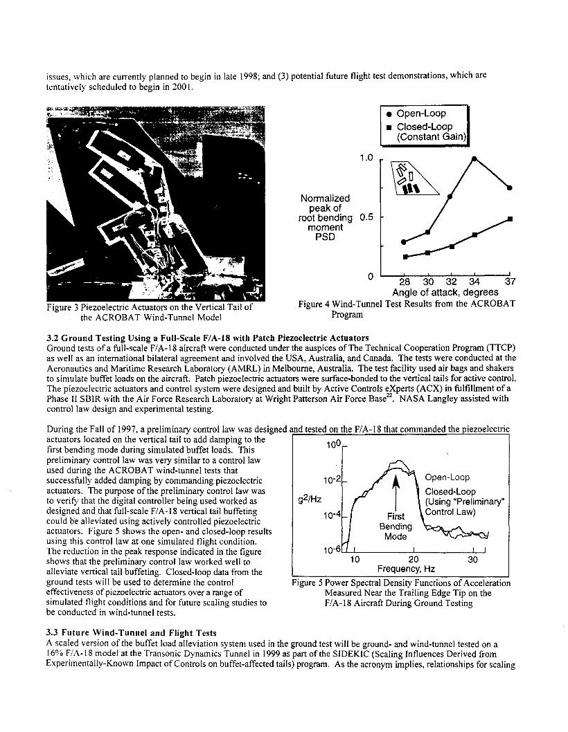
During Phase I of the program, a 16% semi-span model (“Smart Wing”) of a high-performance fighter aircraft was designed and fabricated incorporating three key features: 1) variable spanwise wing twist, 2 ) hingeless, smoothly contoured trailing edge control surfaces and 3) fiber optic pressure and strain transducers. Another identically-scaled model of conventional construction (hinged control surfaces and no wing twist) was fabricated and used as a baseline for comparison. On the Smart Wing model, wing twist is accomplished through the use of two shape memory alloy-actuated torque tubes. The in-board and out-board SMA torque tubes are approximately 5 and 4 inches long, respectively. The torque is transferred from the SMA torque tubes to the wing box via steel shafts. The schematic in Figure 6 depicts the wing twist concept. The hingeless aileron and flap are actuated using shape memory alloy (SMA) tendons. As shown in Figure 7, the hingeless control surface concept reduces the separated flow region on the wing thereby increasing lift to drag ratio, and, as a secondary effect, increasing the aeroelastic reversal speed.
Figure 6: Schematic of Smart Concepts on the Smart Wing Model
The first wind-tunnel test in Phase I took place at the Langley TDT in May 1996. A photograph of the Smart Wing model in the TDT is shown in Figure 8. During the test, 1.25 degrees of twist was achieved using both SMA torque tubes resulting in approximately an 8% improvement in rolling moment relative to the untwisted conventional wing. The
hingeless control surfaces deployed up to 10 degrees, providing between an 8 and 18% increase in rolling moment and approximately an 8% increase in lift, as compared to the results obtained using the conventional control surfaces deployed through the same angles. A complete summary of wind-tunnel test results is presented in reference 24.
The second wind-tunnel test of Phase I is planned for Summer 1998. Phase I1 of the Smart Wing program includes plans to further mature the technologies developed in Phase I, investigate new actuation concepts, and study near term technology transition issues needed to apply the smart concepts to unmanned aircraft. Two wind-tunnel tests in the Langley TDT are currently planned for Phase 11.
Component
Metallic Base - Brass Total Actuator Thickness
, Bonding Polyimide-LaRC-SI@
Conventional Control Surface
Thickness, in Inches, of THUNDER Specimens Specimen 1 Specimen 2 Specimen 3 Specimen 4
0.00 10 0.00 10 0.0020 0.0023 0.00 10 0.0020 0.0020 0.0030 0.0088 0.01 12 0.0 108 0.0121
Hingeless Control Surface
igure 7: Aerodynamic Advantage of Hingeless Control Surface Concept
Figure 8: Smart Wing Model in the Langley TDT
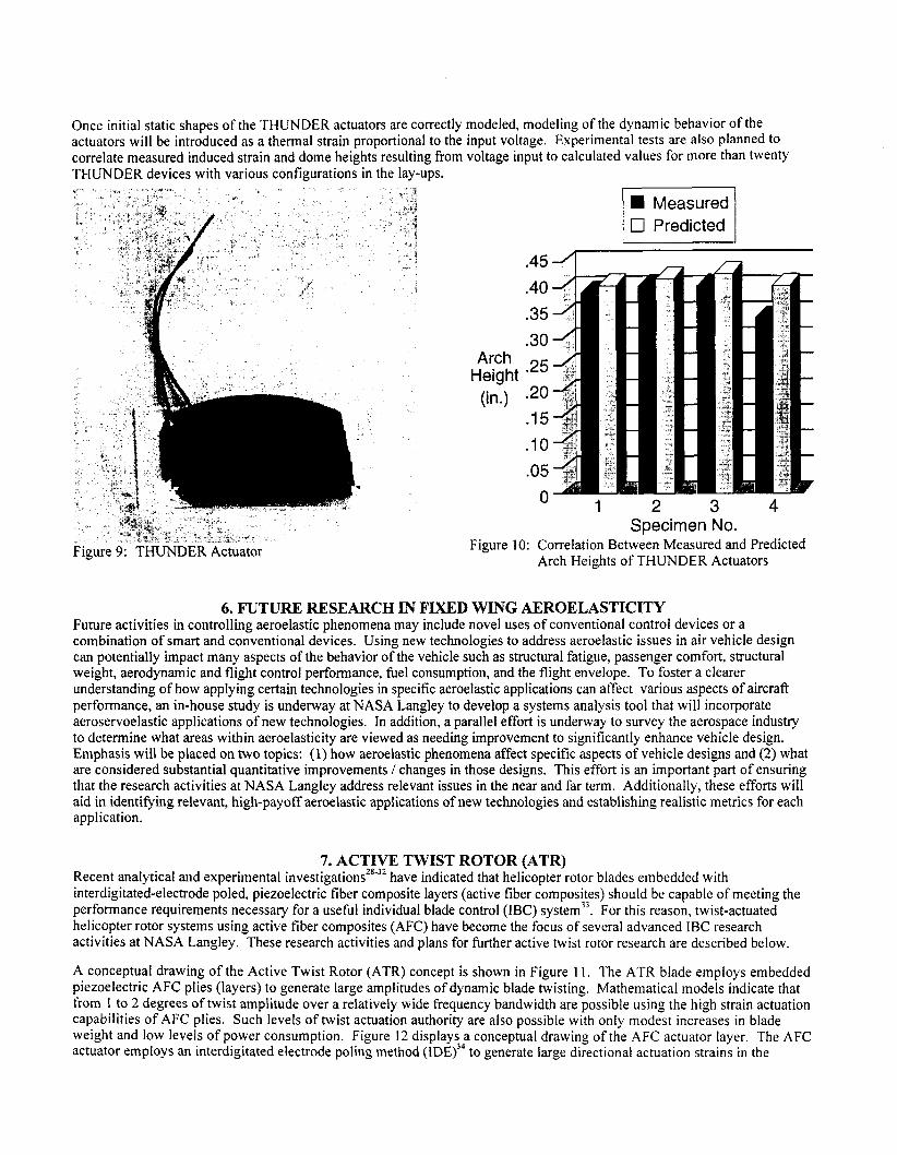
Once initial static shapes of the THUNDER actuators are correctly modeled, modeling of the dynamic behavior of the actuators will be introduced as a thermal strain proportional to the input voltage. Experimental tests are also planned to correlate measured induced strain and dome heights resulting from voltage input to calculated values for more than twenty THUNDER devices with various configurations in the lay-ups.
Figure 9: THUNDER Actuator
a Measured 0 Predicted i I
.45
.40
.35
.30 Arch .25 Height (in.) .20
.15
.10
.05 n
1 2 3 4 Specimen No.
U
Figure 10: Correlation Between Measured and Predicted Arch Heights of THUNDER Actuators
6. FUTURE RESEARCH IN FIXED WING AEROELASTICITY Future activities in controlling aeroelastic phenomena may include novel uses of conventional control devices or a combination of smart and conventional devices. Using new technologies to address aeroelastic issues in air vehicle design can potentially impact many aspects of the behavior of the vehicle such as structural fatigue, passenger comfort, structural weight, aerodynamic and flight control performance, fuel consumption, and the flight envelope. To foster a clearer understanding of how applying certain technologies in specific aeroelastic applications can affect various aspects of aircraft performance, an in-house study is underway at NASA Langley to develop a systems analysis tool that will incorporate aeroservoelastic applications of new technologies. In addition, a parallel effort is underway to survey the aerospace industry to determine what areas within aeroelasticity are viewed as needing improvement to significantly enhance vehicle design. Emphasis will be placed on two topics: (1) how aeroelastic phenomena affect specific aspects of vehicle designs and (2) what are considered substantial quantitative improvements / changes in those designs. This effort is an important part of ensuring that the research activities at NASA Langley address relevant issues in the near and far term. Additionally, these efforts will aid in identifying relevant, high-payoff aeroelastic applications of new technologies and establishing realistic metrics for each application.
7. ACTIVE TWIST ROTOR (ATR) Recent analytical and experimental investigationsz8”* have indicated that helicopter rotor blades embedded with interdigitated-electrode poled, piezoelectric fiber composite layers (active fiber composites) should be capable of meeting the performance requirements necessary for a usehl individual blade control (IBC) ~ystem’~. For this reason, twist-actuated helicopter rotor systems using active fiber composites (AFC) have become the focus of several advanced IBC research activities at NASA Langley. These research activities and plans for hrther active twist rotor research are described below.
A conceptual drawing of the Active Twist Rotor (ATR) concept is shown in Figure 11. The ATR blade employs embedded piezoelectric AFC plies (layers) to generate large amplitudes of dynamic blade twisting. Mathematical models indicate that from 1 to 2 degrees of twist amplitude over a relatively wide frequency bandwidth are possible using the high strain actuation capabilities of AFC plies. Such levels of twist actuation authority are also possible with only modest increases in blade weight and low levels of power consumption. Figure 12 display:: conceptual drawing of the AFC actuator layer. The AFC actuator employs an interdigitated electrode poling method (IDE) to generate large directional actuation strains in the