Aerodynamic Design of Centrifugal Compressor for · PDF fileAerodynamic Design of Centrifugal...
7
70 Vol. 43 No. 2 2010 Aerodynamic Design of Centrifugal Compressor for AT14 Turbocharger TAMAKI Hideaki : Doctor of Engineering, P. E. Jp, Manager, Turbo Machinery and Engine Technology Department, Products Development Center, Corporate Research & Development UNNO Masaru : Manager, Turbo Machinery and Engine Technology Department, Products Development Center, Corporate Research & Development KAWAKUBO Tomoki : Manager, Turbo Machinery and Engine Technology Department, Products Development Center, Corporate Research & Development HIRATA Yutaka : Manager, Business Development Department, Rotating Machinery Operations High boost pressure is required to increase the specific output power of diesel engines. The pressure ratio of compressors for turbochargers has been increased to meet these engine requirements. IHI developed a new turbocharger, AT14 mounting a high pressure ratio centrifugal compressor, for 500 kW class diesel engines. In high pressure ratio centrifugal compressors, it is expected that the complicated flow characteristics related to occurrence of shock wave will deteriorate compressor efficiency and operating range. To avoid these problems, several countermeasures were taken in the aerodynamic design of AT14 centrifugal compressor. Newly designed compressors were realized with the expected performance, stage pressure ratio, and efficiency. This paper outlines the aerodynamic design of the centrifugal compressor for AT14. 1. Introduction Efforts are being made to raise the mean effective pressure (i.e., the work done per engine cycle divided by the piston displacement volume; this corresponds to the pressure change experienced in one cycle) of marine diesel engines to increase the engine power output. To raise the mean effective pressure, it is essential that the pressure ratio and efficiency of the turbocharger be increased. The boost pressure to the engine increases as the mean effective pressure increases, and on some marine engines, the pressure ratio required for the compressor approaches 6.0. To improve the thermal efficiency of an engine, Miller timing is employed (in a combustion cycle known as the Miller cycle, more energy can be extracted by making the expansion ratio of the engine larger than the compression ratio, which can be achieved by closing the intake valve in the middle of the suction stroke). In the Miller cycle, it is necessary that high density air be supplied for a short period of time, and technology that enables the development of an efficient high-pressure ratio turbocharger is indispensable. For this reason, there is fierce competition among marine turbocharger manufacturers to develop a high pressure ratio turbocharger. IHI has developed the AT14 high pressure ratio turbocharger for use with 500 kW class marine engines. For a turbocharger that is to be used with engines in the 500 kW class, a compressor capable of achieving a maximum pressure ratio of 5.0 is required. This paper describes the aerodynamic design of the centrifugal compressor developed for the AT14 turbocharger. 2. Specifications for the compressor Table 1 shows the specifications of the conventional compressor for the AT14 (hereinafter called the conventional compressor) and the high pressure ratio compressor for the AT14 (hereinafter called the new compressor). Figure 1 shows the performance of the conventional compressor and the specifications of the new compressor. Here, the flow coefficient (f), pressure coefficient (µ y ) and work coefficient (µ 0 ) are defined by Equations (1) to (3), as shown below. f r = G DU 01 2 2 2 ......................................................... (1) m y = − ( ) ( ) C p T U 01 1 2 2 1 π g g − .......................................... (2) m 0 02 01 2 2 = − ( ) C p T T U ................................................. (3) C p : Specific heat at constant pressure (J/(kg·K)) D 2 : Outer diameter of impeller (m) G : Mass flow rate (kg/s) P 01 , P 02 : Total pressure (inlet, outlet) (Pa) R : Gas constant (J/(kg·K)) T 01 , T 02 : Total temperature (inlet, outlet) U 2 : Impeller speed (m/s) g : Specific heat ratio p : Pressure ratio (= P P 02 01 )
Transcript of Aerodynamic Design of Centrifugal Compressor for · PDF fileAerodynamic Design of Centrifugal...
70
Vo l . 4 3 N o . 2 2 010
Aerodynamic Design of Centrifugal Compressor
for AT14 Turbocharger
TAMAKI Hideaki : Doctor of Engineering, P. E. Jp, Manager, Turbo Machinery and Engine Technology Department, Products Development Center, Corporate Research & Development UNNO Masaru : Manager, Turbo Machinery and Engine Technology Department, Products Development Center, Corporate Research & Development KAWAKUBO Tomoki : Manager, Turbo Machinery and Engine Technology Department, Products Development Center, Corporate Research & Development HIRATA Yutaka : Manager, Business Development Department, Rotating Machinery Operations
High boost pressure is required to increase the specific output power of diesel engines. The pressure ratio of compressors for turbochargers has been increased to meet these engine requirements. IHI developed a new turbocharger, AT14 mounting a high pressure ratio centrifugal compressor, for 500 kW class diesel engines. In high pressure ratio centrifugal compressors, it is expected that the complicated flow characteristics related to occurrence of shock wave will deteriorate compressor efficiency and operating range. To avoid these problems, several countermeasures were taken in the aerodynamic design of AT14 centrifugal compressor. Newly designed compressors were realized with the expected performance, stage pressure ratio, and efficiency. This paper outlines the aerodynamic design of the centrifugal compressor for AT14.
1. Introduction
Efforts are being made to raise the mean effective pressure (i.e., the work done per engine cycle divided by the piston displacement volume; this corresponds to the pressure change experienced in one cycle) of marine diesel engines to increase the engine power output. To raise the mean effective pressure, it is essential that the pressure ratio and efficiency of the turbocharger be increased. The boost pressure to the engine increases as the mean effective pressure increases, and on some marine engines, the pressure ratio required for the compressor approaches 6.0. To improve the thermal efficiency of an engine, Miller timing is employed (in a combustion cycle known as the Miller cycle, more energy can be extracted by making the expansion ratio of the engine larger than the compression ratio, which can be achieved by closing the intake valve in the middle of the suction stroke). In the Miller cycle, it is necessary that high density air be supplied for a short period of time, and technology that enables the development of an efficient high-pressure ratio turbocharger is indispensable. For this reason, there is fierce competition among marine turbocharger manufacturers to develop a high pressure ratio turbocharger.
IHI has developed the AT14 high pressure ratio turbocharger for use with 500 kW class marine engines. For a turbocharger that is to be used with engines in the 500 kW class, a compressor capable of achieving a maximum pressure ratio of 5.0 is required. This paper describes the aerodynamic design of the centrifugal compressor developed for the AT14 turbocharger.
2. Specifications for the compressor
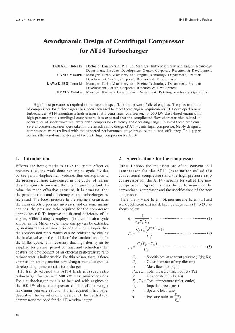
Table 1 shows the specif ications of the conventional compressor for the AT14 (hereinafter cal led the conventional compressor) and the high pressure ratio compressor for the AT14 (hereinafter called the new compressor). Figure 1 shows the performance of the conventional compressor and the specifications of the new compressor.
Here, the flow coefficient (f), pressure coefficient (µy) and work coefficient (µ0) are defined by Equations (1) to (3), as shown below.
fr
=G
D U01 22
2 ......................................................... (1)
my =−( )( )Cp T
U
011
22
1π gg −
.......................................... (2)
m002 01
22
=−( )Cp T T
U ................................................. (3)
Cp : Specific heat at constant pressure (J/(kg·K))D2 : Outer diameter of impeller (m)G : Mass flow rate (kg/s)P01, P02 : Total pressure (inlet, outlet) (Pa)R : Gas constant (J/(kg·K))T01, T02 : Total temperature (inlet, outlet)U2 : Impeller speed (m/s)g : Specific heat ratio
p : Pressure ratio (= P
P02
01
)
71
Vo l . 4 3 N o . 2 2 010
r01 : Density (kg/m3)
r0101
01
=P
RT
To achieve a high pressure ratio, the impeller speed must be increased. Because the impellers (rotors) of the new and conventional compressors have the same outer diameter, an increase in impeller speed corresponds to an increase in rotational speed.
As shown in Table 1, the pressure coefficient of the new compressor is larger than that of the conventional type. Therefore, the work coefficient and rotational speed must both be increased. To increase the work coefficient, the work that the impeller transfers to the fluid must be increased. Equal to the pressure difference between the pressure surface and the suction surface (blade loading), this work is produced by the flow velocity difference between the two surfaces. The flow velocity near the suction surface is larger than that near the pressure surface, and an increase in the blade loading causes an increase in the flow velocity near the suction surface. The work that the impeller transfers to the fluid is also equal to the increment in circumferential momentum of the fluid flowing out of the impeller. Therefore, the deflection of the flow at the impeller outlet, which is determined by the blade shape at the impeller outlet, has a significant effect on this work.
The above-mentioned increases in rotational speed and work coefficient cause an increase in the relative Mach number in the impeller. The increase in the relative Mach number induces a complex flow accompanied by shock waves in the impeller, causing reductions in the efficiency and operating range. The rise in flow velocity in the
impeller increases the velocity in the downstream diffuser as well, and causes an increase in friction loss. When developing the new compressor, attention was paid to the following:
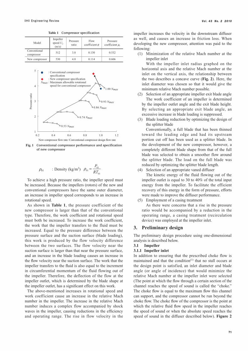
(1) Minimization of the relative Mach number at the impeller inletWith the impeller inlet radius graphed on the
horizontal axis and the relative Mach number at the inlet on the vertical axis, the relationship between the two describes a concave curve (Fig. 2). Here, the inlet diameter was chosen so that it would give the minimum relative Mach number possible.
(2) Selection of an appropriate impeller exit blade angleThe work coefficient of an impeller is determined
by the impeller outlet angle and the exit blade height. By selecting an appropriate exit blade angle, an excessive increase in blade loading is suppressed.
(3) Blade loading reduction by optimizing the design of the splitter bladeConventionally, a full blade that has been thinned
toward the leading edge and had its upstream portion cut off has been used as a splitter blade. In the development of the new compressor, however, a completely different blade shape from that of the full blade was selected to obtain a smoother flow around the splitter blade. The load on the full blade was reduced by optimizing the splitter blade length.
(4) Selection of an appropriate vaned diffuserThe kinetic energy of the fluid flowing out of the
impeller outlet is equal to 30 to 40% of the total input energy from the impeller. To facilitate the efficient recovery of this energy in the form of pressure, efforts were made to improve the diffuser performance.
(5) Employment of a casing treatmentAs there were concerns that a rise in the pressure
ratio would be accompanied by a reduction in the operating range, a casing treatment (recirculation device) was employed at the impeller inlet.
3. Preliminary design
The preliminary design procedure using one-dimensional analysis is described below.3.1 Impeller3.1.1 Impeller inletIn addition to ensuring that the prescribed choke flow is maintained and that the condition(1) that no stall occurs at the design point is satisfied, an inlet diameter and blade angle (or angle of incidence) that would minimize the relative Mach number at the impeller inlet were selected (The point at which the flow through a certain section of the channel reaches the speed of sound is called the “choke.” The choke flow is equal to the maximum flow this channel can support, and the compressor cannot be run beyond the choke flow. The choke flow of the compressor is the point at which the relative fluid flow speed in the impeller reaches the speed of sound or when the absolute speed reaches the speed of sound in the diffuser described below). Figure 2
1
2
3
4
5
0.2 0.4 0.6 0.8 1.0 1.2
New compressor flow rate/Conventional compressor design flow rate
Pre
ssur
e ra
tio
0.53 Nmax
0.86 Nmax
0.93 Nmax
1.00 Nmax
0.74 Nmax
� : Conventional compressor specification� : New compressor specificationNmax : Maximum allowable rotational speed for conventional compressor
Fig. 1 Conventional compressor performance and specification of new compressor
Table 1 Compressor specification
ModelImpeller speed U2
(m/s)
Pressure ratio
Flow coefficient f
Pressure coefficient my
Conventional compressor
512 3.8 0.130 0.532
New compressor 530 4.8 0.114 0.606
72
Vo l . 4 3 N o . 2 2 010
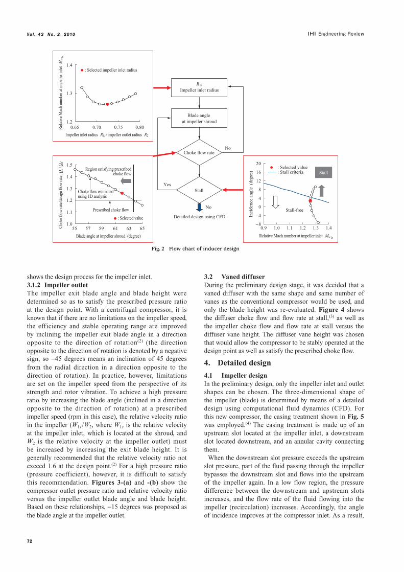
shows the design process for the impeller inlet.3.1.2 Impeller outletThe impeller exit blade angle and blade height were determined so as to satisfy the prescribed pressure ratio at the design point. With a centrifugal compressor, it is known that if there are no limitations on the impeller speed, the efficiency and stable operating range are improved by inclining the impeller exit blade angle in a direction opposite to the direction of rotation(2) (the direction opposite to the direction of rotation is denoted by a negative sign, so -45 degrees means an inclination of 45 degrees from the radial direction in a direction opposite to the direction of rotation). In practice, however, limitations are set on the impeller speed from the perspective of its strength and rotor vibration. To achieve a high pressure ratio by increasing the blade angle (inclined in a direction opposite to the direction of rotation) at a prescribed impeller speed (rpm in this case), the relative velocity ratio in the impeller (W1s /W2, where W1s is the relative velocity at the impeller inlet, which is located at the shroud, and W2 is the relative velocity at the impeller outlet) must be increased by increasing the exit blade height. It is generally recommended that the relative velocity ratio not exceed 1.6 at the design point.(2) For a high pressure ratio (pressure coefficient), however, it is difficult to satisfy this recommendation. Figures 3-(a) and -(b) show the compressor outlet pressure ratio and relative velocity ratio versus the impeller outlet blade angle and blade height. Based on these relationships, -15 degrees was proposed as the blade angle at the impeller outlet.
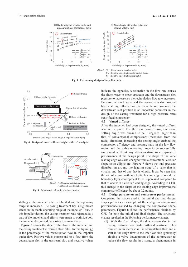
3.2 Vaned diffuserDuring the preliminary design stage, it was decided that a vaned diffuser with the same shape and same number of vanes as the conventional compressor would be used, and only the blade height was re-evaluated. Figure 4 shows the diffuser choke flow and flow rate at stall,(3) as well as the impeller choke flow and flow rate at stall versus the diffuser vane height. The diffuser vane height was chosen that would allow the compressor to be stably operated at the design point as well as satisfy the prescribed choke flow.
4. Detailed design
4.1 Impeller designIn the preliminary design, only the impeller inlet and outlet shapes can be chosen. The three-dimensional shape of the impeller (blade) is determined by means of a detailed design using computational fluid dynamics (CFD). For this new compressor, the casing treatment shown in Fig. 5 was employed.(4) The casing treatment is made up of an upstream slot located at the impeller inlet, a downstream slot located downstream, and an annular cavity connecting them.
When the downstream slot pressure exceeds the upstream slot pressure, part of the fluid passing through the impeller bypasses the downstream slot and flows into the upstream of the impeller again. In a low flow region, the pressure difference between the downstream and upstream slots increases, and the flow rate of the fluid flowing into the impeller (recirculation) increases. Accordingly, the angle of incidence improves at the compressor inlet. As a result,
No
No
YesStall
Detailed design using CFD
R1s
Impeller inlet radius
Blade angle at impeller shroud1.2
1.3
1.4
0.65 0.70 0.75 0.80
Impeller inlet radius R1s / impeller outlet radius R2
Rel
ativ
e M
ach
num
ber a
t im
pelle
r inl
et M
w1s
: Selected impeller inlet radius
−8
−4
0
4
8
12
16
20
0.9 1.0 1.1 1.2 1.3 1.4
Relative Mach number at impeller inlet Mw1s
Inci
denc
e an
gle
(de
gree
)
: Selected value : Stall criteria Stall
1.0
1.1
1.2
1.3
1.4
1.5
55 57 59 61 63 65
Blade angle at impeller shroud (degree)
Cho
ke fl
ow ra
te/d
esig
n flo
w ra
te Q
c/Q
d
Stall-free
Choke flow rate
Region satisfying prescribed choke flow
Prescribed choke flow
Choke flow estimated using 1D analysis
: Selected value
Fig. 2 Flow chart of inducer design
73
Vo l . 4 3 N o . 2 2 010
stalling at the impeller inlet is inhibited and the operating range is increased. The casing treatment has a significant effect on the stable operating range of the impeller. Thus, in this impeller design, the casing treatment was regarded as a part of the impeller, and efforts were made to optimize both the impeller design and the casing treatment shape.
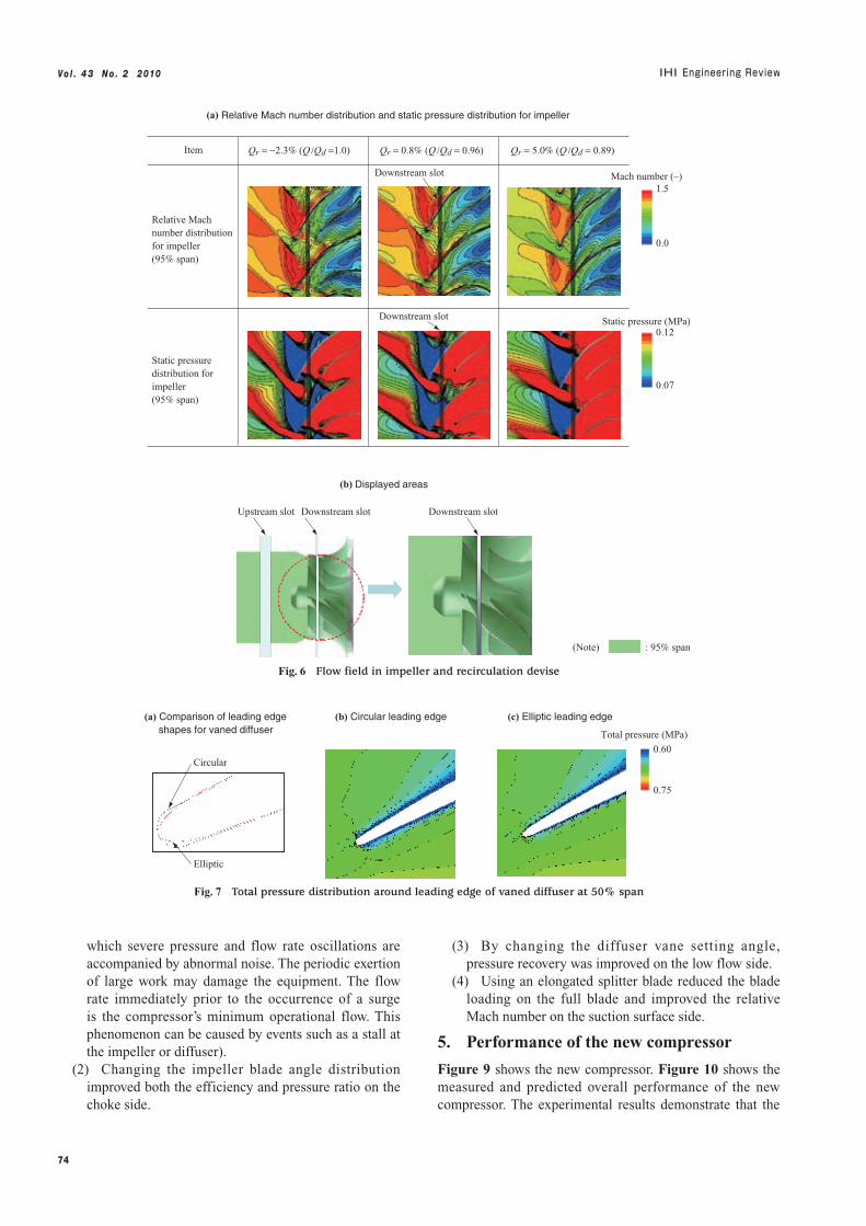
Figure 6 shows the state of the flow in the impeller and the casing treatment at various flow rates. In this figure, Qr
is the percentage of the recirculation flow in the impeller outlet flow. Positive values correspond to a flow from the downstream slot to the upstream slot, and negative values
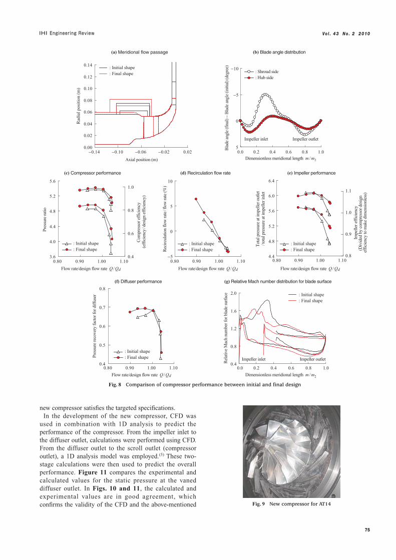
indicate the opposite. A reduction in the flow rate causes the shock wave to move upstream and the downstream slot pressure to increase, so the recirculation flow rate increases. Because the shock wave and the downstream slot position have a strong influence on the recirculation flow rate, the downstream slot position is an important parameter in the design of the casing treatment for a high pressure ratio centrifugal compressor.4.2 Vaned diffuserAfter the impeller had been designed, the vaned diffuser was redesigned. For the new compressor, the vane setting angle was chosen to be 3 degrees larger than that of conventional compressors (measured from the radial direction). Increasing the setting angle enabled the compressor efficiency and pressure ratio in the low flow region and the stable operating range to be successfully increased without any deterioration in compressor performance at the design point. The shape of the vane leading edge was also changed from a conventional circular shape to an elliptic arc. Figure 7 shows the total pressure distribution around the leading edge of a vane that is circular and that of one that is elliptic. It can be seen that the use of a vane with an elliptic leading edge allowed the boundary layer development to be suppressed compared to that of one with a circular leading edge. According to CFD, this change to the shape of the leading edge improved the compressor efficiency by about 0.2 points.4.3 Design parameters and compressor performanceComparing the shapes used in the initial and final design stages provides an example of the change in compressor performance caused by changing the compressor shape parameters. Figure 8 shows the performance obtained by CFD for both the initial and final shapes. The structural change resulted in the following performance changes.
(1) With the final shape, the downstream slot in the casing treatment was made further downstream. This resulted in an increase in the recirculation flow and a shift in the surge flow to the low flow side (gradually closing a valve downstream of the compressor to reduce the flow results in a surge, a phenomenon in
0.8
0.9
1.0
1.1
1.2
1.3
0.6 0.8 1.0 1.2
Diffuser vane height / blade height at impeller outlet b3/b2
Flo
w r
ate
/des
ign
flow
rat
e Q
/Qd Diffuser choke flow rate
Diffuser stall region
Impeller stall region
Choke flow of impeller
: Selected value
Compressor choke region
Unstable operating region for compressor
Diffuser stall flow
Impeller stall flow
Stable operating region for compressor
Fig. 4 Design of vaned diffuser height with 1-D analysis
Annular cavityDownstream slot
Upstream slot
(Notes) P1 : Upstream slot static pressure P2 : Downstream slot static pressure
P2P1
:P1<P2:P1>P2
Fig. 5 Schematic of recirculation device
(a) Blade height at impeller outlet and pressure ratio at compressor outlet
(b) Blade height at impeller outlet and relative velocity ratio
3.0
3.5
4.0
4.5
5.0
5.5
6.0
7 8 9 10 11
Blade height at impeller outlet b2 (mm) Blade height at impeller outlet b2 (mm)
Pre
ssur
e ra
tio
: Selected value
Pressure ratio 4.8
(Notes) bb2 : Blade angle at impeller outlet W1s : Relative velocity at impeller inlet at shroud W2 : Relative velocity at impeller outlet
1.0
1.2
1.4
1.6
1.8
2.0
2.2
2.4
7 8 9 10 11
Rel
ativ
e ve
loci
ty r
atio
W1s
/W2
: bb2 = −10° : bb2 = −15° : bb2 = −20° : bb2 = −25°
W1s /W2 = 1.6
: bb2 = −10° : bb2 = −15° : bb2 = −20° : bb2 = −25°
: Selected value
Fig. 3 Preliminary design of impeller outlet
74
Vo l . 4 3 N o . 2 2 010
which severe pressure and flow rate oscillations are accompanied by abnormal noise. The periodic exertion of large work may damage the equipment. The flow rate immediately prior to the occurrence of a surge is the compressor’s minimum operational flow. This phenomenon can be caused by events such as a stall at the impeller or diffuser).
(2) Changing the impeller blade angle distribution improved both the efficiency and pressure ratio on the choke side.
(3) By changing the diffuser vane setting angle, pressure recovery was improved on the low flow side.
(4) Using an elongated splitter blade reduced the blade loading on the full blade and improved the relative Mach number on the suction surface side.
5. Performance of the new compressor
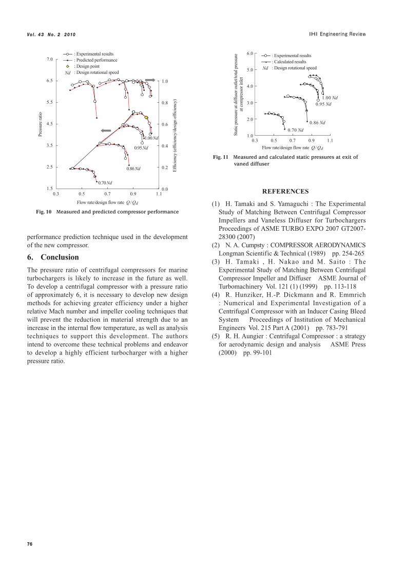
Figure 9 shows the new compressor. Figure 10 shows the measured and predicted overall performance of the new compressor. The experimental results demonstrate that the
0.60
0.75
Elliptic
Circular
Total pressure (MPa)
(a) Comparison of leading edge shapes for vaned diffuser
(b) Circular leading edge (c) Elliptic leading edge
Fig. 7 Total pressure distribution around leading edge of vaned diffuser at 50% span
(a) Relative Mach number distribution and static pressure distribution for impeller
Qr = −2.3% (Q /Qd =1.0)
(b) Displayed areas
Relative Mach number distribution for impeller (95% span)
Static pressure distribution for impeller (95% span)
Qr = 0.8% (Q /Qd = 0.96) Qr = 5.0% (Q /Qd = 0.89)
Upstream slot Downstream slot
(Note) : 95% span
Downstream slot
0.0
1.5
0.12
0.07
Mach number (–)
Static pressure (MPa)
Item
Downstream slot
Downstream slot
Fig. 6 Flow field in impeller and recirculation devise
75
Vo l . 4 3 N o . 2 2 010
new compressor satisfies the targeted specifications. In the development of the new compressor, CFD was
used in combination with 1D analysis to predict the performance of the compressor. From the impeller inlet to the diffuser outlet, calculations were performed using CFD. From the diffuser outlet to the scroll outlet (compressor outlet), a 1D analysis model was employed.(5) These two-stage calculations were then used to predict the overall performance. Figure 11 compares the experimental and calculated values for the static pressure at the vaned diffuser outlet. In Figs. 10 and 11, the calculated and experimental values are in good agreement, which confirms the validity of the CFD and the above-mentioned Fig. 9 New compressor for AT14
−0.14
(a) Meridional flow passage (b) Blade angle distribution
−10
−5
0
50.0 0.2 0.4 0.6 0.8 1.0
Dimensionless meridional length m / m2
Bla
de a
ngle
(fin
al) −
Bla
de a
ngle
(ini
tial)
(deg
ree)
Axial position (m)
Rad
ial p
osit
ion
(m)
: Shroud side : Hub side
Impeller inlet Impeller outlet
0.00
0.02
0.04
0.06
0.08
0.10
0.12
0.14
−0.10 −0.06 −0.02 0.02
: Initial shape : Final shape
3.6
4.0
4.4
4.8
5.2
5.6
0.80 0.90 1.00 1.10
Flow rate/design flow rate Q / Qd
Pres
sure
ratio
0.4
0.6
0.8
1.0
Com
pres
sor e
ffic
ienc
y (e
ffic
ienc
y/d
esig
n ef
fici
ency
)
: Initial shape : Final shape
−5
0
5
10
0.80 0.90 1.00 1.10
Rec
ircu
latio
n fl
ow ra
te/f
low
rate
(%)
4.4
4.8
5.2
5.6
6.0
6.4
Tot
al p
ress
ure
at im
pelle
r out
let
/tot
al p
ress
ure
at im
pelle
r inl
et0.8
0.9
1.0
1.1
Impe
ller e
ffic
ienc
y(D
ivid
ed b
y co
mpr
esso
r des
ign
effi
cien
cy to
mak
e di
men
sion
less
)0.4
0.5
0.6
0.7
0.8
0.80 0.90 1.00 1.10
Flow rate/design flow rate Q / Qd
Pres
sure
reco
very
fact
or fo
r dif
fuse
r
0.4
0.8
1.2
1.6
2.0
0.0 0.2 0.4 0.6 0.8 1.0
Rel
ativ
e M
ach
num
ber f
or b
lade
sur
face
Impeller inlet Impeller outlet
(c) Compressor performance (d) Recirculation flow rate (e) Impeller performance
(f) Diffuser performance (g) Relative Mach number distribution for blade surface
Dimensionless meridional length m / m2
Flow rate/design flow rate Q / Qd
: Initial shape : Final shape
: Initial shape : Final shape
: Initial shape : Final shape
0.80 0.90 1.00 1.10
Flow rate/design flow rate Q / Qd
: Initial shape : Final shape
Fig. 8 Comparison of compressor performance between initial and final design
76
Vo l . 4 3 N o . 2 2 010
performance prediction technique used in the development of the new compressor.
6. Conclusion
The pressure ratio of centrifugal compressors for marine turbochargers is likely to increase in the future as well. To develop a centrifugal compressor with a pressure ratio of approximately 6, it is necessary to develop new design methods for achieving greater efficiency under a higher relative Mach number and impeller cooling techniques that will prevent the reduction in material strength due to an increase in the internal flow temperature, as well as analysis techniques to support this development. The authors intend to overcome these technical problems and endeavor to develop a highly efficient turbocharger with a higher pressure ratio.
REFERENCES
(1) H. Tamaki and S. Yamaguchi : The Experimental Study of Matching Between Centrifugal Compressor Impellers and Vaneless Diffuser for Turbochargers Proceedings of ASME TURBO EXPO 2007 GT2007- 28300 (2007)
(2) N. A. Cumpsty : COMPRESSOR AERODYNAMICS Longman Scientific & Technical (1989) pp. 254-265
(3) H. Tamaki , H. Nakao and M. Saito : The Experimental Study of Matching Between Centrifugal Compressor Impeller and Diffuser ASME Journal of Turbomachinery Vol. 121 (1) (1999) pp. 113-118
(4) R. Hunziker, H.-P. Dickmann and R. Emmrich : Numerical and Experimental Investigation of a Centrifugal Compressor with an Inducer Casing Bleed System Proceedings of Institution of Mechanical Engineers Vol. 215 Part A (2001) pp. 783-791
(5) R. H. Aungier : Centrifugal Compressor : a strategy for aerodynamic design and analysis ASME Press (2000) pp. 99-101
1.5
2.5
3.5
4.5
5.5
6.5
0.3 0.5 0.7 0.9 1.1
Flow rate/design flow rate Q / Qd
Pres
sure
ratio
0.0
0.2
0.4
0.6
0.8
1.0
Eff
icie
ncy
(eff
icie
ncy/
desi
gn e
ffic
ienc
y)
0.70 Nd
1.00 Nd
0.95 Nd
0.86 Nd
: Experimental results : Predicted performance : Design point : Design rotational speedNd
7.0
Fig. 10 Measured and predicted compressor performance
1.0
2.0
3.0
4.0
5.0
6.0
0.3 0.5 0.7 0.9 1.1
Flow rate/design flow rate Q / Qd
Stat
ic p
ress
ure
at d
iffu
ser o
utle
t/tot
al p
ress
ure
at c
ompr
esso
r inl
et
0.70 Nd
1.00 Nd0.95 Nd
0.86 Nd
: Experimental results : Calculated results : Design rotational speedNd
Fig. 11 Measured and calculated static pressures at exit of vaned diffuser