AERODROME PHYSICAL CHARACTERISTICS · AERODROME PHYSICAL CHARACTERISTICS ... Airport Planning...
64
i AIRPORT STANDARDS DIRECTIVE 510 [ASD 510] AERODROME PHYSICAL CHARACTERISTICS AIRPORT STANDARDS DIVISION DEPARTMENT OF CIVIL AVIATION MALAYSIA
Transcript of AERODROME PHYSICAL CHARACTERISTICS · AERODROME PHYSICAL CHARACTERISTICS ... Airport Planning...
i
AIRPORT STANDARDS DIRECTIVE 510
[ASD 510]
AERODROME PHYSICAL
CHARACTERISTICS
AIRPORT STANDARDS DIVISION
DEPARTMENT OF CIVIL AVIATION
MALAYSIA
ii
This Airport Standards Directive is published and enforced by the Director
General of Civil Aviation Malaysia under the provision of the Section 24O
Civil Aviation Act 1969 (Act3) – Amendment 2006.
© Department of Civil Aviation Malaysia 2016
First published April 2016
Printed and distributed by Department of Civil Aviation Malaysia,
Level 1, Block Podium B, No 27 Persiaran Perdana, Precinct 4, 62618 PUTRAJAYA
i
TABLE OF CONTENTS
Page
INTRODUCTION 1
OBJECTIVE 1
APPLICABILITY 2
AUTHORITY 3
1. Runways 2
2. Runway shoulders 11
3. Runway turn pads 12
4. Runway strips 15
5. Runway end safety areas 20
6. Clearways 22
7. Stopways 27
8. Radio altimeter operating area 26
9. Taxiways 27
10. Taxiway shoulders 36
11. Taxiway strips 36
Holding bays, runway-holding positions, intermediate holding
positions and road-holding positions 36
13. Aprons 41
14. Deviations 44
ATTACHMENT A. Guidance material supplementary to ASD301
1. Number, siting and orientation of runways i
2. Clearways and stopways ii
3. Calculation of declared distances iv
4. Slopes on a runway iv
5. Drainage characteristics of the movement area and
adjacent areas ix
6. Strips x
7. Runway end safety areas xi
8. Location of threshold xi
9. The ACN-PCN method of reporting pavement strength xii
1
INTRODUCTION
1. In exercise of the powers conferred by regulation 12(c) of the Civil
Aviation (Aerodrome Operations) Regulations 2016, the Director
General makes this Airport Standards Directive.
2. This Airport Standards Directive is published by the Director General
under section 24O of Civil Aviation Act 1969 [Act 3] – Amendment
2006.
3. This Airport Standards Directive contains specifications that prescribe
the physical characteristics that shall be provided at aerodrome
4. This Directive has been written in general terms. Specific advice could
be obtained from the Authority at:
Department of Civil Aviation
Airport Standards Division
Level 1 Block Podium B Precinct 4
No. 27 Persiaran Perdana
62618 Putrajaya.
Phone: 03-88714000
Fax : 03-88714335
5. Responsibility for ensuring safety, regularity and efficiency of aircraft
operations at aerodromes rests with contracting states to the
Convention on International Civil Aviation. Contracting states are
obliged to observe Articles 28 and 37 of the Convention and shall
ensure aerodromes and aerodrome facilities, infrastructures and
services provided are consistent with Standards and Recommended
Practices [SARP] developed by ICAO.
OBJECTIVE
6. This Airport Standards Directive [Directive] is intended to serve
guidance to aerodrome operators pertaining to ICAO mandatory
requirement on the physical characteristic of aerodromes.
2
APPLICABILITY
7. The specification in this directive shall apply for aerodromes used for
international operations, in any state of Malaysia.
AUTHORITY
8. The Authority is the Director General of Civil Aviation Malaysia under
the provision of Section 24O Civil Aviation Act 1969 (Act 3).
RUNWAYS
NUMBER AND ORIENTATION OF RUNWAYS
9. Many factors affect the determination of the orientation, siting and
number of runways.
10. One important factor is the usability factor, as determined by the
wind distribution, which is specified hereunder. Another important
factor is the alignment of the runway to facilitate the provision of
approaches conforming to the approach surface specifications of
Airport Standards Diretives related to obstacle restriction and removal.
In Attachment A, Section 1, information is given concerning these and
other factors.
11. When a new instrument runway is being located, particular attention
needs to be given to areas over which aeroplanes will be required to
fly when following instrument approach and missed approach
procedures, so as to ensure that obstacles in these areas or other
factors will not restrict the operation of the aeroplanes for which the
runway is intended.
12. The number and orientation of runways at an aerodrome should be
such that the usability factor of the aerodrome is not less than 95 per
cent for the aeroplanes that the aerodrome is intended to serve.
13. The siting and orientation of runways at an aerodrome should, where
possible, be such that the arrival and departure tracks minimize
interference with areas approved for residential use and other noise-
sensitive areas close to the aerodrome in order to avoid future noise
problems.
3
Note : Guidance on how to address noise problems is provided in the
Airport Planning Manual (Doc 9184), Part 2, and in Guidance on the
Balanced Approach to Aircraft Noise Management (Doc 9829).
CHOICE OF MAXIMUM PERMISSIBLE CROSSWIND COMPONENTS
14. In the application of lause 12 it should be assumed that landing or
take-off of aeroplanes is, in normal circumstances, precluded when
the crosswind component exceeds:
— 37 km/h (20 kt) in the case of aeroplanes whose reference field
length is 1 500 m or over, except that when poor runway braking
action owing to an insufficient longitudinal coefficient of friction is
experienced with some frequency, a crosswind component not
exceeding 24 km/h (13 kt) should be assumed;
— 24 km/h (13 kt) in the case of aeroplanes whose reference field
length is 1 200 m or up to but not including 1 500 m;and
— 19 km/h (10 kt) in the case of aeroplanes whose reference field
length is less than 1 200 m.
Note : In Attachment A, Section 1, guidance is given on factors
affecting the calculation of the estimate of the usability factor and
allowances which may have to be made to take account of the
effect of unusual circumstances.
DATA TO BE USED
15. The selection of data to be used for the calculation of the usability
factor should be based on reliable wind distribution statistics that
extend over as long a period as possible, preferably of not less than
five years. The observations used should be made at least eight times
daily and spaced at equal intervals of time.
Note : These winds are mean winds. Reference to the need for some
allowance for gusty conditions is made in Attachment A, Section 1.
4
LOCATION OF THRESHOLD
16. A threshold should normally be located at the extremity of a runway
unless operational considerations justify the choice of another
location.
Note : Guidance on the siting of the threshold is given in Attachment
A, Section 11.
17. When it is necessary to displace a threshold, either permanently or
temporarily, from its normal location, account should be taken of the
various factors which may have a bearing on the location of the
threshold. Where this displacement is due to an unserviceable runway
condition, a cleared and graded area of at least 60 m in length
should be available between the unserviceable area and the
displaced threshold. Additional distance should also be provided to
meet the requirements of the runway end safety area as appropriate.
Note : Guidance on factors which may be considered in the
determination of the location of a displaced threshold is given in
Attachment A, Section 11.
ACTUAL LENGTH OF RUNWAYS
PRIMARY RUNWAY
18. Except as provided in clause 20, the actual runway length to be
provided for a primary runway should be adequate to meet the
operational requirements of the aeroplanes for which the runway is
intended and should be not less than the longest length determined
by applying the corrections for local conditions to the operations and
performance characteristics of the relevant aeroplanes.
Note 1 : This specification does not necessarily mean providing for
operations by the critical aeroplane at its maximummass.
Note 2 : Both take-off and landing requirements need to be
considered when determining the length of runway to be provided
and the need for operations to be conducted in both directions of
the runway.
Note 3 : Local conditions that may need to be considered include
elevation, temperature, runway slope, humidity and the runway
surface characteristics.
5
Note 4 : When performance data on aeroplanes for which the runway
is intended are not known, guidance on the determination of the
actual length of a primary runway by application of general
correction factors is given in the ICAO Aerodrome Design Manual
(Doc 9157), Part 1.
SECONDARY RUNWAY
19. The length of a secondary runway should be determined similarly to
primary runways except that it needs only to be adequate for those
aeroplanes which require to use that secondary runway in addition to
the other runway or runways in order to obtain a usability factor of at
least 95 per cent.
RUNWAYS WITH STOPWAYS OR CLEARWAYS
20. Where a runway is associated with a stopway or clearway, an actual
runway length less than that resulting from application of 1.7 or 1.8, as
appropriate, may be considered satisfactory, but in such a case any
combination of runway, stopway and clearway provided should
permit compliance with the operational requirements fortake-off and
landing of the aeroplanes the runway is intended to serve.
Note : Guidance on use of stopways and clearways is given in
Attachment A, Section 2.
WIDTH OF RUNWAYS
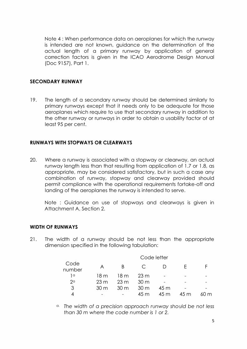
21. The width of a runway should be not less than the appropriate
dimension specified in the following tabulation:
Code letter
Code
number A B C D E F
1a 18 m 18 m 23 m - - -
2a 23 m 23 m 30 m - - -
3 30 m 30 m 30 m 45 m - -
4 - - 45 m 45 m 45 m 60 m
a. The width of a precision approach runway should be not less
than 30 m where the code number is 1 or 2.
6
Note 1 : The combinations of code numbers and letters for which
widths are specified have been developed for typical aeroplane
characteristics.
Note 2 : Factors affecting runway width are given in the ICAO
Aerodrome Design Manual (Doc 9157), Part 1.
MINIMUM DISTANCE BETWEEN PARALLEL RUNWAYS
22. Where parallel non-instrument runways are intended for simultaneous
use, the minimum distance between their centre lines should be:
— 210 m where the higher code number is 3 or 4;
— 150 m where the higher code number is 2; and
— 120 m where the higher code number is 1.
Note : Procedures for wake turbulence categorization of aircraft and
wake turbulence separation minima are contained in the Procedures
for Air Navigation Services — Air Traffic Management (PANS-ATM),
Doc 4444, Chapter 4,4.9 and Chapter 5, 5.8, respectively.
23. Where parallel instrument runways are intended for simultaneous use
subject to conditions specified in the ICAO PANS-ATM (Doc 4444) and
the ICAO PANS-OPS (Doc 8168), Volume I, the minimum distance
between their centre lines should be:
— 1 035 m for independent parallel approaches;
— 915 m for dependent parallel approaches;
— 760 m for independent parallel departures;
— 760 m for segregated parallel operations;
except that:
a) for segregated parallel operations the specified minimum
distance:
1) may be decreased by 30 m for each 150 m that the arrival
runway is staggered toward the arriving aircraft, to a
minimum of 300 m; and
7
2) should be increased by 30 m for each 150 m that the arrival
runway is staggered away from the arriving aircraft;
b) for independent parallel approaches, combinations of
minimum distances and associated conditions other than those
specified in the PANS-ATM (Doc 4444) may be applied when it is
determined that such combinations would not adversely affect
the safety of aircraft operations.
Note : Procedures and facilities requirements for simultaneous
operations on parallel or near-parallel instrument runways are
contained in the PANS-ATM (Doc 4444), Chapter 6 and the PANS-
OPS (Doc 8168), Volume I, Part III, Section 2, and Volume II, Part I,
Section 3; Part II, Section 1; and Part III, Section 3, and relevant
guidance is contained in the Manual on Simultaneous Operations
on Parallel or Near-Parallel Instrument Runways (SOIR) (Doc 9643).
SLOPE OF RUNWAYS
LONGITUDINAL SLOPES
24. The slope computed by dividing the difference between the
maximum and minimum elevation along the runway centre line by
the runway length should not exceed:
— 1 per cent where the code number is 3 or 4; and
— 2 per cent where the code number is 1 or 2.
25. Along no portion of a runway should the longitudinal slope exceed:
— 1.25 per cent where the code number is 4, except that for
the first and last quarter of the length of the runway the
longitudinal slope should not exceed 0.8 per cent;
— 1.5 per cent where the code number is 3, except that for the
first and last quarter of the length of a precision approach
runway category II or III the longitudinal slope should not
exceed 0.8 per cent; and
— 2 per cent where the code number is 1 or 2.
8
LONGITUDINAL SLOPE CHANGES
26. Where slope changes cannot be avoided, a slope change between
two consecutive slopes should not exceed:
— 1.5 per cent where the code number is 3 or 4; and
— 2 per cent where the code number is 1 or 2.
Note : Guidance on slope changes before a runway is given in
Attachment A, Section 4.
27. The transition from one slope to another should be accomplished by a
curved surface with a rate of change not exceeding:
— 0.1 per cent per 30 m (minimum radius of curvature of 30 000
m) where the code number is 4;
— 0.2 per cent per 30 m (minimum radius of curvature of 15 000
m) where the code number is 3; and
— 0.4 per cent per 30 m (minimum radius of curvature of 7 500
m) where the code number is 1 or 2.
SIGHT DISTANCE
28. Where slope changes cannot be avoided, they should be such that
there will be an unobstructed line of sight from:
— any point 3 m above a runway to all other points 3 m above
the runway within a distance of at least half the length of the
runway where the code letter is C, D, E or F;
— any point 2 m above a runway to all other points 2 m above
the runway within a distance of at least half the length of the
runway where the code letter is B; and
— any point 1.5 m above a runway to all other points 1.5 m
above the runway within a distance of at least half the length
of the runway where the code letter is A.
Note : Consideration will have to be given to providing an
unobstructed line of sight over the entire length of a single
runway where a full-length parallel taxiway is not available.
Where an aerodrome has intersecting runways, additional
criteria on the line of sight of the intersection area would need
to be considered for operational safety. See the ICAO
Aerodrome Design Manual (Doc 9157), Part 1.
9
DISTANCE BETWEEN SLOPE CHANGES
29. Undulations or appreciable changes in slopes located close together
along a runway should be avoided. The distance between the points
of intersection of two successive curves should not be less than:
a) the sum of the absolute numerical values of the corresponding
slope changes multiplied by the appropriate value as follows:
— 30 000 m where the code number is 4;
— 15 000 m where the code number is 3; and
— 5 000 m where the code number is 1 or 2; or
b) 45 m;
whichever is greater.
Note : Guidance on implementing this specification is given in
Attachment A, Section 4.
TRANSVERSE SLOPES
30. To promote the most rapid drainage of water, the runway surface
should, if practicable, be cambered except where a single crossfall
from high to low in the direction of the wind most frequently
associated with rain would ensure rapid drainage. The transverse
slope should ideally be:
— 1.5 per cent where the code letter is C, D, E or F; and
— 2 per cent where the code letter is A or B;
but in any event should not exceed 1.5 per cent or 2 per cent, as
applicable, nor be less than 1 per cent except at runway or taxiway
intersections where flatter slopes may be necessary.
For a cambered surface the transverse slope on each side of the
centre line should be symmetrical.
Note : On wet runways with crosswind conditions the problem of
aquaplaning from poor drainage is apt to be accentuated. In
Attachment A, Section 7, information is given concerning this problem
and other relevant factors.
10
31. The transverse slope should be substantially the same throughout the
length of a runway except at an intersection with another runway or
a taxiway where an even transition should be provided taking
account of the need for adequate drainage.
Note : Guidance on transverse slope is given in the ICAO Aerodrome
Design Manual (Doc 9157), Part 3.
STRENGTH OF RUNWAYS
32. A runway should be capable of withstanding the traffic of aeroplanes
the runway is intended to serve.
SURFACE OF RUNWAYS
33. The surface of a runway shall be constructed without irregularities that
would impair the runway surface friction characteristics or otherwise
adversely affect the take-off or landing of an aeroplane.
Note 1 : Surface irregularities may adversely affect the take-off or
landing of an aeroplane by causing excessive bouncing, pitching,
vibration, or other difficulties in the control of an aeroplane.
Note 2 : Guidance on design tolerances and other information is
given in Attachment A, Section 5. Additional guidance is included in
the ICAO Aerodrome Design Manual (Doc 9157), Part 3.
34. A paved runway shall be so constructed or resurfaced as to provide
surface friction characteristics at or above the minimum friction level.
35. The surface of a paved runway should be evaluated when
constructed or resurfaced to determine that the surface friction
characteristics achieve the design objectives.
Note : Guidance on surface friction characteristics of a new or
resurfaced runway is given in Attachment A, Section 7. Additional
guidance is included in the ICAO Airport Services Manual (Doc 9137),
Part 2.
36. Measurements of the surface friction characteristics of a new or
resurfaced paved runway should be made with a continuous friction
measuring device using self-wetting features.
11
Note : Guidance on surface friction characteristics of new runway
surfaces is given in Attachment A, Section 7. Additional guidance is
included in the ICAO Airport Services Manual (Doc 9137), Part 2.
37. The average surface texture depth of a new surface should be not
less than 1.0 mm.
Note : Macrotexture and microtexture are taken into consideration in
order to provide the required surface friction characteristics.
Guidance on surface design is given in Attachment A, Section 8.
Note 2 : Guidance on methods used to measure surface texture is
given in the ICAO Airport Services Manual (Doc 9137), Part 2.
Note 3 : Guidance on design and methods for improving surface
texture is given in the ICAO Aerodrome Design Manual (Doc 9157),
Part 3.
38. When the surface is grooved or scored, the grooves or scorings should
be either perpendicular to the runway centre line or parallel to non-
perpendicular transverse joints, where applicable.
Note : Guidance on methods for improving the runway surface
texture is given in the ICAO Aerodrome Design Manual (Doc 9157),
Part 3.
RUNWAY SHOULDERS
GENERAL
Note : Guidance on characteristics and treatment of runway
shoulders is given in Attachment A, Section 9, and in the ICAO
Aerodrome Design Manual (Doc 9157), Part 1.
39. Runway shoulders should be provided for a runway where the code
letter is D or E, and the runway width is less than 60 m.
40. Runway shoulders should be provided for a runway where the code
letter is F.
12
WIDTH OF RUNWAY SHOULDERS
41. The runway shoulders should extend symmetrically on each side of the
runway so that the overall width of the runway and its shoulders is not
less than:
— 60 m where the code letter is D or E; and
— 75 m where the code letter is F.
SLOPES ON RUNWAY SHOULDERS
42. The surface of the shoulder that abuts the runway should be flush with
the surface of the runway and its transverse slope should not exceed
2.5 per cent.
STRENGTH OF RUNWAY SHOULDERS
43. A runway shoulder should be prepared or constructed so as to be
capable, in the event of an aeroplane running off the runway, of
supporting the aeroplane without inducing structural damage to the
aeroplane and of supporting ground vehicles which may operate on
the shoulder.
Note : Guidance on strength of runway shoulders is given in the ICAO
Aerodrome Design Manual (Doc 9157), Part 1.
RUNWAY TURN PADS GENERAL
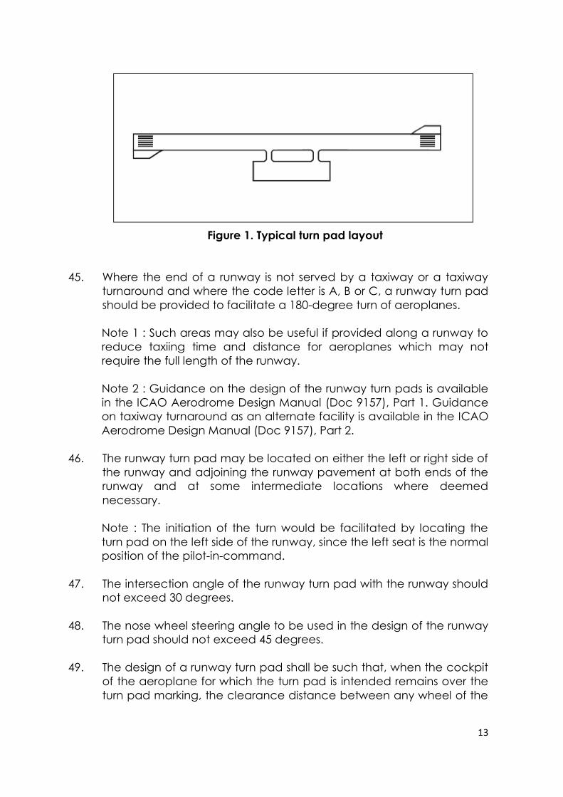
44. Where the end of a runway is not served by a taxiway or a taxiway
turnaround and where the code letter is D, E or F, a runway turn pad
shall be provided to facilitate a 180-degree turn of aeroplanes. (See
Figure 1.)
13
Figure 1. Typical turn pad layout
45. Where the end of a runway is not served by a taxiway or a taxiway
turnaround and where the code letter is A, B or C, a runway turn pad
should be provided to facilitate a 180-degree turn of aeroplanes.
Note 1 : Such areas may also be useful if provided along a runway to
reduce taxiing time and distance for aeroplanes which may not
require the full length of the runway.
Note 2 : Guidance on the design of the runway turn pads is available
in the ICAO Aerodrome Design Manual (Doc 9157), Part 1. Guidance
on taxiway turnaround as an alternate facility is available in the ICAO
Aerodrome Design Manual (Doc 9157), Part 2.
46. The runway turn pad may be located on either the left or right side of
the runway and adjoining the runway pavement at both ends of the
runway and at some intermediate locations where deemed
necessary.
Note : The initiation of the turn would be facilitated by locating the
turn pad on the left side of the runway, since the left seat is the normal
position of the pilot-in-command.
47. The intersection angle of the runway turn pad with the runway should
not exceed 30 degrees.
48. The nose wheel steering angle to be used in the design of the runway
turn pad should not exceed 45 degrees.
49. The design of a runway turn pad shall be such that, when the cockpit
of the aeroplane for which the turn pad is intended remains over the
turn pad marking, the clearance distance between any wheel of the
14
aeroplane landing gear and the edge of the turn pad shall be not
less than that given by the following tabulation:
Code letter Clearance
A 1.5 m
B 2.25 m
C 3 m if the turn pad is intended to be
used by aeroplanes with a wheel base
less than 18 m; 4.5 m if the turn pad is
intended to be used by aeroplanes with
a wheel base equal to or greater than
18 m.
D 4.5 m
E 4.5 m
F 4.5 m
Wheel base means the distance from the nose gear to the geometric
centre of the main gear.
50. Where severe weather conditions and resultant lowering of surface
friction characteristics prevail, a larger wheel-to-edge clearance of 6
m should be provided where the code letter is E or F.
SLOPES ON RUNWAY TURN PADS
51. The longitudinal and transverse slopes on a runway turn pad should
be sufficient to prevent the accumulation of water on the surface
and facilitate rapid drainage of surface water. The slopes should be
the same as those on the adjacent runway pavement surface.
STRENGTH OF RUNWAY TURN PADS
52. The strength of a runway turn pad should be at least equal to that of
the adjoining runway which it serves, due consideration being given
to the fact that the turn pad will be subjected to slow-moving traffic
making hard turns and consequent higher stresses on the pavement.
15
Note : Where a runway turn pad is provided with flexible pavement,
the surface would need to be capable of withstanding the horizontal
shear forces exerted by the main landing gear tires during turning
manoeuvres.
SURFACE OF RUNWAY TURN PADS
53. The surface of a runway turn pad shall not have surface irregularities
that may cause damage to an aeroplane using the turn pad.
54. The surface of a runway turn pad should be so constructed or
resurfaced as to provide surface friction characteristics at least equal
to that of the adjoining runway.
SHOULDERS FOR RUNWAY TURN PADS
55. The runway turn pads should be provided with shoulders of such width
as is necessary to prevent surface erosion by the jet blast of the most
demanding aeroplane for which the turn pad is intended, and any
possible foreign object damage to the aeroplane engines.
Note : As a minimum, the width of the shoulders would need to cover
the outer engine of the most demanding aeroplane and thus may be
wider than the associated runway shoulders.
56. The strength of runway turn pad shoulders should be capable of
withstanding the occasional passage of the aeroplane it is designed
to serve without inducing structural damage to the aeroplane and to
the supporting ground vehicles that may operate on the shoulder.
RUNWAY STRIPS
GENERAL
57. A runway and any associated stopways shall be included in a strip.
LENGTH OF RUNWAY STRIPS
58. A strip shall extend before the threshold and beyond the end of the
runway or stopway for a distance of at least:
16
— 60 m where the code number is 2, 3 or 4;
— 60 m where the code number is 1 and the runway is an
instrument one; and
— 30 m where the code number is 1 and the runway is a non-
instrument one.
WIDTH OF RUNWAY STRIPS
59. A strip including a precision approach runway shall, wherever
practicable, extend laterally to a distance of at least:
— 150 m where the code number is 3 or 4; and
— 75 m where the code number is 1 or 2;
on each side of the centre line of the runway and its extended centre
line throughout the length of the strip.
60. A strip including a non-precision approach runway should extend
laterally to a distance of
at least:
— 150 m where the code number is 3 or 4; and
— 75 m where the code number is 1 or 2;
on each side of the centre line of the runway and its extended centre
line throughout the length of the strip.
61. A strip including a non-instrument runway should extend on each side
of the centre line of the runway and its extended centre line
throughout the length of the strip, to a distance of at least:
— 75 m where the code number is 3 or 4;
— 40 m where the code number is 2; and
— 30 m where the code number is 1.
17
OBJECTS ON RUNWAY STRIPS
Note : See ICAO Annex 14 Vol. I clause 9.9 for information regarding
siting of equipment and installations on runway strips.
62. An object situated on a runway strip which may endanger
aeroplanes should be regarded as an obstacle and should, as far as
practicable, be removed.
63. No fixed object, other than visual aids required for air navigation or
those required for aircraft safety purposes and which must be sited on
the runway strip, and satisfying the relevant frangibility requirement in
ASD501, shall be permitted on a runway strip:
a) within 77.5 m of the runway centre line of a precision approach
runway category I, II or III where the code number is 4 and the
code letter is F; or
b) within 60 m of the runway centre line of a precision approach
runway category I, II or III where the code number is 3 or 4; or
c) within 45 m of the runway centre line of a precision approach
runway category I where the code number is 1 or 2.No mobile
object shall be permitted on this part of the runway strip during the
use of the runway for landing or take-off.
GRADING OF RUNWAY STRIPS
64. That portion of a strip of an instrument runway within a distance of at
least:
— 75 m where the code number is 3 or 4; and
— 40 m where the code number is 1 or 2;
from the centre line of the runway and its extended centre line should
provide a graded area for aeroplanes which the runway is intended
to serve in the event of an aeroplane running off the runway.
Note : Guidance on grading of a greater area of a strip including a
precision approach runway where the code number is 3 or 4 is given
in Attachment A, Section 9.
18
65. That portion of a strip of a non-instrument runway within a distance of
at least:
— 75 m where the code number is 3 or 4;
— 40 m where the code number is 2; and
— 30 m where the code number is 1;
from the centre line of the runway and its extended centre line should
provide a graded area for aeroplanes which the runway is intended
to serve in the event of an aeroplane running off the runway.
66. The surface of that portion of a strip that abuts a runway, shoulder or
stopway shall be flush with the surface of the runway, shoulder or
stopway.
67. That portion of a strip to at least 30 m before a threshold should be
prepared against blast erosion in order to protect a landing
aeroplane from the danger of an exposed edge.
68. Where the areas in clause 67 have paved surfaces, they should be
able to withstand the occasional passage of the critical aeroplane for
runway pavement design.
Note : The area adjacent to the end of a runway may be referred to
as a blast pad.
SLOPES ON RUNWAY STRIPS
LONGITUDINAL SLOPES
69. A longitudinal slope along that portion of a strip to be graded should
not exceed:
— 1.5 per cent where the code number is 4;
— 1.75 per cent where the code number is 3; and
— 2 per cent where the code number is 1 or 2.
LONGITUDINAL SLOPE CHANGES
70. Slope changes on that portion of a strip to be graded should be as
gradual as practicable and abrupt changes or sudden reversals of
slopes avoided.
19
TRANSVERSE SLOPES
71. Transverse slopes on that portion of a strip to be graded should be
adequate to prevent the accumulation of water on the surface but
should not exceed:
— 2.5 per cent where the code number is 3 or 4; and
— 3 per cent where the code number is 1 or 2;
except that to facilitate drainage the slope for the first 3 m outward
from the runway, shoulder or stopway edge should be negative as
measured in the direction away from the runway and may be as
great as 5 per cent.
72. The transverse slopes of any portion of a strip beyond that to be
graded should not exceed an upward slope of 5 per cent as
measured in the direction away from the runway.
STRENGTH OF RUNWAY STRIPS
73. That portion of a strip of an instrument runway within a distance of at
least:
— 75 m where the code number is 3 or 4; and
— 40 m where the code number is 1 or 2;
from the centre line of the runway and its extended centre line should
be so prepared or constructed as to minimize hazards arising from
differences in load-bearing capacity to aeroplanes which the runway
is intended to serve in the event of an aeroplane running off the
runway.
Note : Guidance on preparation of runway strips is given in the ICAO
Aerodrome Design Manual (Doc 9157), Part 1.
74. That portion of a strip containing a non-instrument runway within a
distance of at least:
— 75 m where the code number is 3 or 4;
— 40 m where the code number is 2; and
20
— 30 m where the code number is 1;
from the centre line of the runway and its extended centre line should
be so prepared or constructed as to minimize hazards arising from
differences in load-bearing capacity to aeroplanes which the runway
is intended to serve in the event of an aeroplane running off the
runway.
RUNWAY END SAFETY AREAS
GENERAL
75. A runway end safety area shall be provided at each end of a runway
strip where:
— the code number is 3 or 4; and
— the code number is 1 or 2 and the runway is an instrument
one.
Note : Guidance on runway end safety areas is given in Attachment
A, Section 10.
76. A runway end safety area should be provided at each end of a
runway strip where the code number is 1 or 2 and the runway is a non-
instrument one.
DIMENSIONS OF RUNWAY END SAFETY AREAS
77. A runway end safety area shall extend from the end of a runway strip
to a distance of at least 90 m where:
— the code number is 3 or 4; and
— the code number is 1 or 2 and the runway is an instrument
one.
If an arresting system is installed, the above length may be reduced,
based on the design specification of the system, subject to
acceptance.
Note : Guidance on arresting systems is given in Attachment A,
Section 10.
21
78. A runway end safety area should, as far as practicable, extend from
the end of a runway strip to a distance of at least:
— 240 m where the code number is 3 or 4; or a reduced length
when an arresting system is installed;
— 120 m where the code number is 1 or 2 and the runway is an
instrument one; or a reduced length when an arresting system
is installed; and
— 30 m where the code number is 1 or 2 and the runway is a non-
instrument one.
79. The width of a runway end safety area shall be at least twice that of
the associated runway.
80. The width of a runway end safety area should, wherever practicable,
be equal to that of the graded portion of the associated runway strip.
OBJECTS ON RUNWAY END SAFETY AREAS
Note : See ICAO Annex 14 Vol. I clause 9.9 for information regarding
siting of equipment and installations on runway end safety areas.
81. An object situated on a runway end safety area which may
endanger aeroplanes should be regarded as an obstacle and should,
as far as practicable, be removed.
CLEARING AND GRADING OF RUNWAY END SAFETY AREAS
82. A runway end safety area should provide a cleared and graded area
for aeroplanes which the runway is intended to serve in the event of
an aeroplane undershooting or overrunning the runway.
Note : The surface of the ground in the runway end safety area does
not need to be prepared to the same quality as the runway strip. See,
however, clause 86.
22
SLOPES ON RUNWAY END SAFETY AREAS
GENERAL
83. The slopes of a runway end safety area should be such that no part of
the runway end safety area penetrates the approach or take-off
climb surface.
LONGITUDINAL SLOPES
84. The longitudinal slopes of a runway end safety area should not
exceed a downward slope of 5 per cent. Longitudinal slope changes
should be as gradual as practicable and abrupt changes or sudden
reversals of slopes avoided.
TRANSVERSE SLOPES
85. The transverse slopes of a runway end safety area should not exceed
an upward or downward slope of 5 per cent. Transitions between
differing slopes should be as gradual as practicable.
STRENGTH OF RUNWAY END SAFETY AREAS
86. A runway end safety area should be so prepared or constructed as to
reduce the risk of damage to an aeroplane undershooting or
overrunning the runway, enhance aeroplane deceleration and
facilitate the movement of rescue and fire fighting vehicles as
required in clauses 23 to 25 ASD 702 : Rescue and Fire Fighting.
Note : Guidance on the strength of a runway end safety area is given
in the ICAO Aerodrome Design Manual (Doc 9157),Part 1.
CLEARWAYS
Note : The inclusion of detailed specifications for clearways in this
section is not intended to imply that a clearway has to be provided.
Attachment A, Section 2, provides information on the use of
clearways.
23
LOCATION OF CLEARWAYS
87. The origin of a clearway should be at the end of the take-off run
available.
LENGTH OF CLEARWAYS
88. The length of a clearway should not exceed half the length of the
take-off run available.
WIDTH OF CLEARWAYS
89. A clearway should extend laterally to a distance of at least 75 m on
each side of the extended centre line of the runway.
SLOPES ON CLEARWAYS
90. The ground in a clearway should not project above a plane having
an upward slope of 1.25 per cent, the lower limit of this plane being a
horizontal line which:
a) is perpendicular to the vertical plane containing the runway
centre line; and
b) passes through a point located on the runway centre line at the
end of the take-off run available.
Note : Because of transverse or longitudinal slopes on a runway,
shoulder or strip, in certain cases the lower limit of the clearway plane
specified above may be below the corresponding elevation of the
runway, shoulder or strip. It is not intended that these surfaces be
graded to conform with the lower limit of the clearway plane nor is it
intended that terrain or objects which are above the clearway plane
beyond the end of the strip but below the level of the strip be
removed unless it is considered they may endanger aeroplanes.
91. Abrupt upward changes in slope should be avoided when the slope
on the ground in a clearway is relatively small or when the mean
slope is upward. In such situations, in that portion of the clearway
within a distance of 22.5 m or half the runway width whichever is
greater on each side of the extended centre line, the slopes, slope
changes and the transition from runway to clearway should generally
24
conform with those of the runway with which the clearway is
associated.
OBJECTS ON CLEARWAYS
92. An object situated on a clearway which may endanger aeroplanes in
the air should be regarded as an obstacle and should be removed.
STOPWAYS
Note : The inclusion of detailed specifications for stopways in this
section is not intended to imply that a stopway has to be provided.
Attachment A, Section 2, provides information on the use of stopways.
WIDTH OF STOPWAYS
93. A stopway shall have the same width as the runway with which it is
associated.
SLOPES ON STOPWAYS
94. Slopes and changes in slope on a stopway, and the transition from a
runway to a stopway,should comply with the specifications of clause
24 to 30 for the runway with which the stopway is associated except
that:
a) the limitation in clause 25 of a 0.8 per cent slope for the first and
last quarter of the length of a runway need not beapplied to the
stopway; and
b) at the junction of the stopway and runway and along the
stopway the maximum rate of slope change may be 0.3 per cent
per 30 m (minimum radius of curvature of 10 000 m) for a runway
where the code number is 3 or 4.
STRENGTH OF STOPWAYS
95. A stopway should be prepared or constructed so as to be capable, in
the event of an abandoned take-off, of supporting the aeroplane
which the stopway is intended to serve without inducing structural
damage to the aeroplane.
25
Note : Attachment A, Section 2, presents guidance relative to the
support capability of a stopway.
SURFACE OF STOPWAYS
96. The surface of a paved stopway shall be so constructed or resurfaced
as to provide surface friction characteristics at or above those of the
associated runway.
26
RADIO ALTIMETER OPERATING AREA
GENERAL
97. A radio altimeter operating area should be established in the pre-
threshold area of a precision approach runway.
LENGTH OF THE AREA
98. A radio altimeter operating area should extend before the threshold
for a distance of at least 300 m.
WIDTH OF THE AREA
99. A radio altimeter operating area should extend laterally, on each side
of the extended centre line of the runway, to a distance of 60 m,
except that, when special circumstances so warrant, the distance
may be reduced to no less than 30 m if an aeronautical study
indicates that such reduction would not affect the safety of
operations of aircraft.
LONGITUDINAL SLOPE CHANGES
100. On a radio altimeter operating area, slope changes should be
avoided or kept to a minimum. Where slope changes cannot be
avoided, the slope changes should be as gradual as practicable and
abrupt changes or sudden reversals of slopes avoided. The rate of
change between two consecutive slopes should not exceed 2 per
cent per 30 m.
Note : Guidance on radio altimeter operating area is given in
Attachment A, Section 4.3, and in the Manual of All-Weather
Operations, (Doc 9365), Section 5.2. Guidance on the use of radio
altimeter is given in the PANS-OPS, Volume II, Part II, Section 1.
27
TAXIWAYS
Note : Unless otherwise indicated the requirements in this section are
applicable to all types of taxiways.
GENERAL
101. Taxiways should be provided to permit the safe and expeditious
surface movement of aircraft.
Note : Guidance on layout of taxiways is given in the ICAO
Aerodrome Design Manual (Doc 9157), Part 2.
102. Sufficient entrance and exit taxiways for a runway should be provided
to expedite the movement of aeroplanes to and from the runway
and provision of rapid exit taxiways considered when traffic volumes
are high.
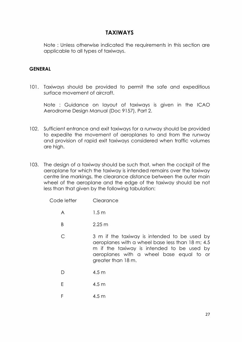
103. The design of a taxiway should be such that, when the cockpit of the
aeroplane for which the taxiway is intended remains over the taxiway
centre line markings, the clearance distance between the outer main
wheel of the aeroplane and the edge of the taxiway should be not
less than that given by the following tabulation:
Code letter Clearance
A 1.5 m
B 2.25 m
C 3 m if the taxiway is intended to be used by
aeroplanes with a wheel base less than 18 m; 4.5
m if the taxiway is intended to be used by
aeroplanes with a wheel base equal to or
greater than 18 m.
D 4.5 m
E 4.5 m
F 4.5 m
28
Note 1 : Wheel base means the distance from the nose gear to the
geometric centre of the main gear.
Note 2 : Where the code letter is F and the traffic density is high, a
wheel-to-edge clearance greater than 4.5 m may be provided to
permit higher taxiing speeds.
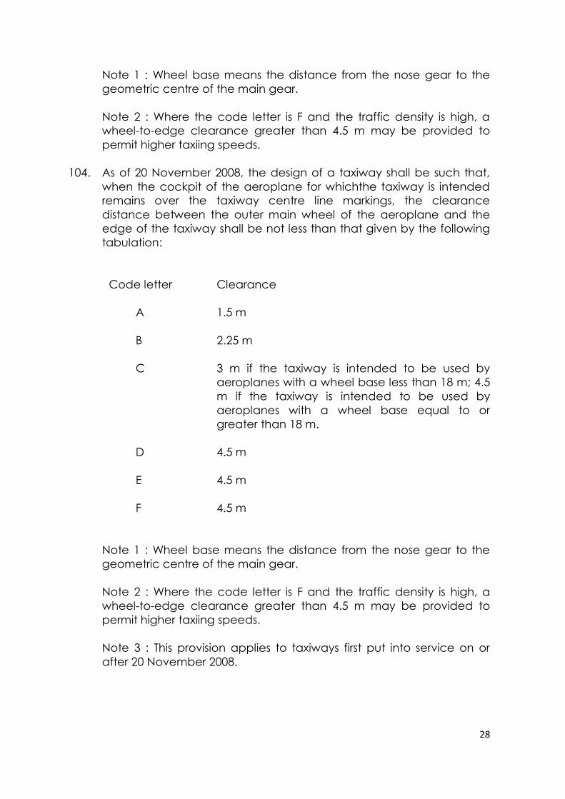
104. As of 20 November 2008, the design of a taxiway shall be such that,
when the cockpit of the aeroplane for whichthe taxiway is intended
remains over the taxiway centre line markings, the clearance
distance between the outer main wheel of the aeroplane and the
edge of the taxiway shall be not less than that given by the following
tabulation:
Code letter Clearance
A 1.5 m
B 2.25 m
C 3 m if the taxiway is intended to be used by
aeroplanes with a wheel base less than 18 m; 4.5
m if the taxiway is intended to be used by
aeroplanes with a wheel base equal to or
greater than 18 m.
D 4.5 m
E 4.5 m
F 4.5 m
Note 1 : Wheel base means the distance from the nose gear to the
geometric centre of the main gear.
Note 2 : Where the code letter is F and the traffic density is high, a
wheel-to-edge clearance greater than 4.5 m may be provided to
permit higher taxiing speeds.
Note 3 : This provision applies to taxiways first put into service on or
after 20 November 2008.
29
WIDTH OF TAXIWAYS
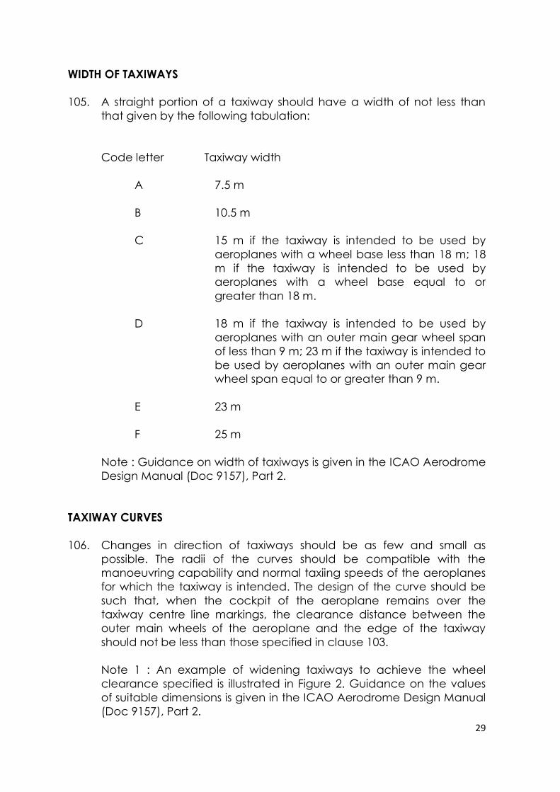
105. A straight portion of a taxiway should have a width of not less than
that given by the following tabulation:
Code letter Taxiway width
A 7.5 m
B 10.5 m
C 15 m if the taxiway is intended to be used by
aeroplanes with a wheel base less than 18 m; 18
m if the taxiway is intended to be used by
aeroplanes with a wheel base equal to or
greater than 18 m.
D 18 m if the taxiway is intended to be used by
aeroplanes with an outer main gear wheel span
of less than 9 m; 23 m if the taxiway is intended to
be used by aeroplanes with an outer main gear
wheel span equal to or greater than 9 m.
E 23 m
F 25 m
Note : Guidance on width of taxiways is given in the ICAO Aerodrome
Design Manual (Doc 9157), Part 2.
TAXIWAY CURVES
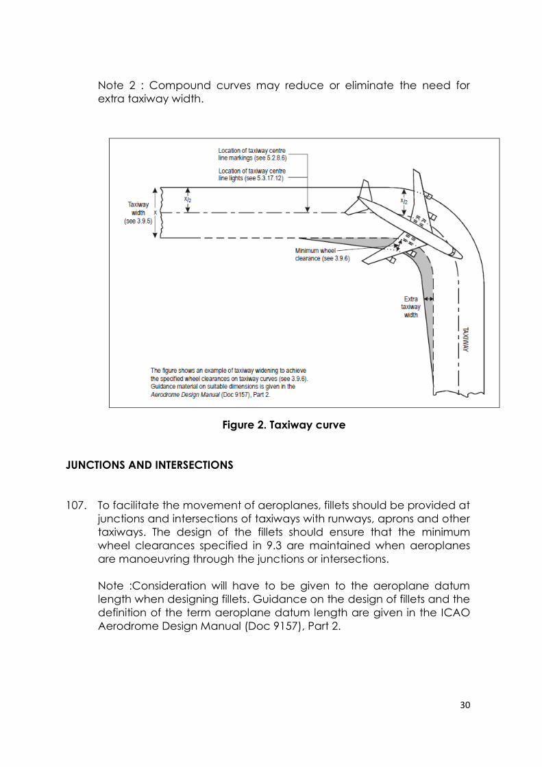
106. Changes in direction of taxiways should be as few and small as
possible. The radii of the curves should be compatible with the
manoeuvring capability and normal taxiing speeds of the aeroplanes
for which the taxiway is intended. The design of the curve should be
such that, when the cockpit of the aeroplane remains over the
taxiway centre line markings, the clearance distance between the
outer main wheels of the aeroplane and the edge of the taxiway
should not be less than those specified in clause 103.
Note 1 : An example of widening taxiways to achieve the wheel
clearance specified is illustrated in Figure 2. Guidance on the values
of suitable dimensions is given in the ICAO Aerodrome Design Manual
(Doc 9157), Part 2.
30
Note 2 : Compound curves may reduce or eliminate the need for
extra taxiway width.
Figure 2. Taxiway curve
JUNCTIONS AND INTERSECTIONS
107. To facilitate the movement of aeroplanes, fillets should be provided at
junctions and intersections of taxiways with runways, aprons and other
taxiways. The design of the fillets should ensure that the minimum
wheel clearances specified in 9.3 are maintained when aeroplanes
are manoeuvring through the junctions or intersections.
Note :Consideration will have to be given to the aeroplane datum
length when designing fillets. Guidance on the design of fillets and the
definition of the term aeroplane datum length are given in the ICAO
Aerodrome Design Manual (Doc 9157), Part 2.
31
TAXIWAY MINIMUM SEPARATION DISTANCES
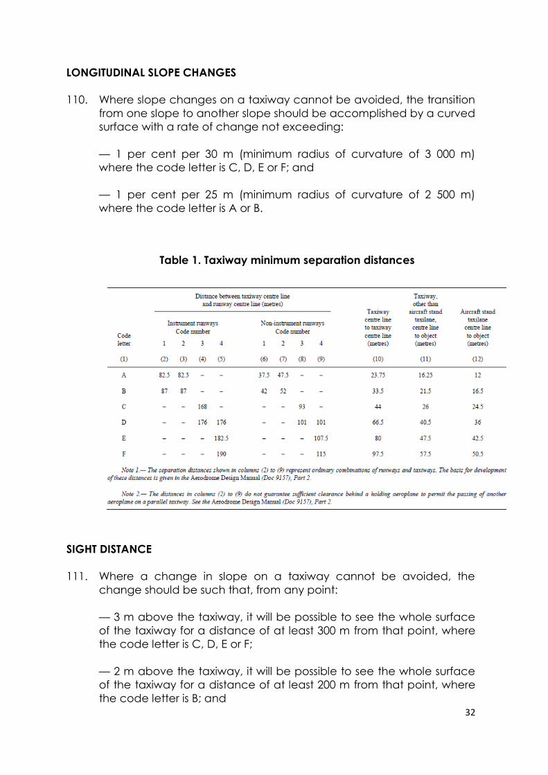
108. The separation distance between the centre line of a taxiway and the
centre line of a runway, the centre line of a parallel taxiway or an
object should not be less than the appropriate dimension specified in
Table 1, except that it may be permissible to operate with lower
separation distances at an existing aerodrome if an aeronautical
study indicates that such lower separation distances would not
adversely affect the safety or significantly affect the regularity of
operations of aeroplanes.
Note 1 : Guidance on factors which may be considered in the
aeronautical study is given in the ICAO Aerodrome Design Manual
(Doc 9157), Part 2.
Note 2 : ILS and MLS installations may also influence the location of
taxiways due to interferences to ILS and MLS signals by a taxiing or
stopped aircraft. Information on critical and sensitive areas
surrounding ILS and MLS installations is contained in Annex 10, Volume
I, Attachments C and G (respectively).
Note 3 : The separation distances of Table 3-1, column 10, do not
necessarily provide the capability of making a normal turn from one
taxiway to another parallel taxiway. Guidance for this condition is
given in the Aerodrome Design Manual (Doc 9157), Part 2.
Note 4 : The separation distance between the centre line of an
aircraft stand taxilane and an object shown in Table 3-1, column 12,
may need to be increased when jet exhaust wake velocity may
cause hazardous conditions for ground servicing.
SLOPES ON TAXIWAYS
LONGITUDINAL SLOPES
109. The longitudinal slope of a taxiway should not exceed:
— 1.5 per cent where the code letter is C, D, E or F; and
— 3 per cent where the code letter is A or B.
32
LONGITUDINAL SLOPE CHANGES
110. Where slope changes on a taxiway cannot be avoided, the transition
from one slope to another slope should be accomplished by a curved
surface with a rate of change not exceeding:
— 1 per cent per 30 m (minimum radius of curvature of 3 000 m)
where the code letter is C, D, E or F; and
— 1 per cent per 25 m (minimum radius of curvature of 2 500 m)
where the code letter is A or B.
Table 1. Taxiway minimum separation distances
SIGHT DISTANCE
111. Where a change in slope on a taxiway cannot be avoided, the
change should be such that, from any point:
— 3 m above the taxiway, it will be possible to see the whole surface
of the taxiway for a distance of at least 300 m from that point, where
the code letter is C, D, E or F;
— 2 m above the taxiway, it will be possible to see the whole surface
of the taxiway for a distance of at least 200 m from that point, where
the code letter is B; and
33
— 1.5 m above the taxiway, it will be possible to see the whole surface
of the taxiway for a distance of at least 150 m from that point, where
the code letter is A.
TRANSVERSE SLOPES
112. The transverse slopes of a taxiway should be sufficient to prevent the
accumulation of water on the surface of the taxiway but should not
exceed:
— 1.5 per cent where the code letter is C, D, E or F; and
— 2 per cent where the code letter is A or B.
See clause 143 regarding transverse slopes on an aircraft stand
taxilane.
STRENGTH OF TAXIWAYS
113. The strength of a taxiway should be at least equal to that of the
runway it serves, due consideration being given to the fact that a
taxiway will be subjected to a greater density of traffic and, as a result
of slow moving and stationary aeroplanes, to higher stresses than the
runway it serves.
Note : Guidance on the relation of the strength of taxiways to the
strength of runways is given in the ICAO Aerodrome Design Manual
(Doc 9157), Part 3.
SURFACE OF TAXIWAYS
114. The surface of a taxiway should not have irregularities that cause
damage to aeroplane structures.
115. The surface of a paved taxiway should be so constructed or
resurfaced as to provide suitable surface friction characteristics.
Note : Suitable surface friction characteristics are those surface
properties required on taxiways that assure safe operation of
aeroplanes.
34
RAPID EXIT TAXIWAYS
Note : The following specifications detail requirements particular to
rapid exit taxiways. See Figure 3. General requirements for taxiways
also apply to this type of taxiway. Guidance on the provision, location
and design of rapid exit taxiways is included in the Aerodrome Design
Manual (Doc 9157), Part 2.
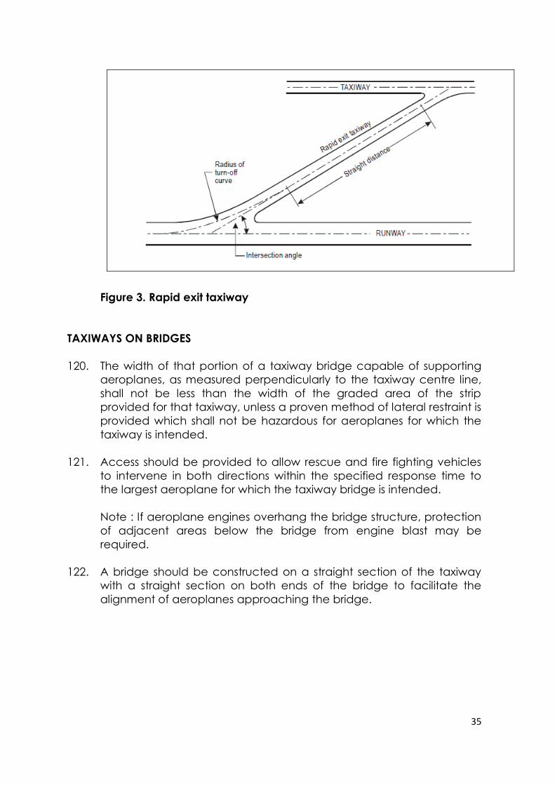
116. A rapid exit taxiway should be designed with a radius of turn-off curve
of at least:
— 550 m where the code number is 3 or 4; and
— 275 m where the code number is 1 or 2;
to enable exit speeds under wet conditions of:
— 93 km/h where the code number is 3 or 4; and
— 65 km/h where the code number is 1 or 2.
Note : The locations of rapid exit taxiways along a runway are based
on several criteria described in the Aerodrome Design Manual (Doc
9157), Part 2, in addition to different speed criteria.
117. The radius of the fillet on the inside of the curve at a rapid exit taxiway
should be sufficient to provide a widened taxiway throat in order to
facilitate early recognition of the entrance and turn-off onto the
taxiway.
118. A rapid exit taxiway should include a straight distance after the turn-
off curve sufficient for an exiting aircraft to come to a full stop clear of
any intersecting taxiway.
119. The intersection angle of a rapid exit taxiway with the runway should
not be greater than 45° nor less than 25° and preferably should be
30°.
35
Figure 3. Rapid exit taxiway
TAXIWAYS ON BRIDGES
120. The width of that portion of a taxiway bridge capable of supporting
aeroplanes, as measured perpendicularly to the taxiway centre line,
shall not be less than the width of the graded area of the strip
provided for that taxiway, unless a proven method of lateral restraint is
provided which shall not be hazardous for aeroplanes for which the
taxiway is intended.
121. Access should be provided to allow rescue and fire fighting vehicles
to intervene in both directions within the specified response time to
the largest aeroplane for which the taxiway bridge is intended.
Note : If aeroplane engines overhang the bridge structure, protection
of adjacent areas below the bridge from engine blast may be
required.
122. A bridge should be constructed on a straight section of the taxiway
with a straight section on both ends of the bridge to facilitate the
alignment of aeroplanes approaching the bridge.
36
TAXIWAY SHOULDERS
Note : Guidance on characteristics of taxiway shoulders and on
shoulder treatment is given in the ICAO Aerodrome Design Manual
(Doc 9157), Part 2.
123. Straight portions of a taxiway where the code letter is C, D, E or F
should be provided with shoulders which extend symmetrically on
each side of the taxiway so that the overall width of the taxiway and
its shoulders on straight portions is not less than:
— 60 m where the code letter is F;
— 44 m where the code letter is E;
— 38 m where the code letter is D; and
— 25 m where the code letter is C.
On taxiway curves and on junctions or intersections where increased
pavement is provided, the shoulder width should be not less than that
on the adjacent straight portions of the taxiway.
124. When a taxiway is intended to be used by turbine-engined
aeroplanes, the surface of the taxiway shoulder should be so
prepared as to resist erosion and the ingestion of the surface material
by aeroplane engines.
TAXIWAY STRIPS
Note : Guidance on characteristics of taxiway strips is given in the
ICAO Aerodrome Design Manual (Doc 9157), Part 2.
GENERAL
125. A taxiway, other than an aircraft stand taxilane, shall be included in a
strip.
WIDTH OF TAXIWAY STRIPS
126. A taxiway strip should extend symmetrically on each side of the
centre line of the taxiway throughout the length of the taxiway to at
least the distance from the centre line given in Table 1, column 11.
37
OBJECTS ON TAXIWAY STRIPS
Note : See ICAO Annex 14 Vol. I clause 9.9 for information regarding
siting of equipment and installations on taxiway strips.
127. The taxiway strip should provide an area clear of objects which may
endanger taxiing aeroplanes.
Note : Consideration will have to be given to the location and design
of drains on a taxiway strip to prevent damage to an aeroplane
accidentally running off a taxiway. Suitably designed drain covers
may be required.
GRADING OF TAXIWAY STRIPS
128. The centre portion of a taxiway strip should provide a graded area to
a distance from the centre line of the taxiway of at least:
— 11 m where the code letter is A;
— 12.5 m where the code letter is B or C;
— 19 m where the code letter is D;
— 22 m where the code letter is E; and
— 30 m where the code letter is F.
SLOPES ON TAXIWAY STRIPS
129. The surface of the strip should be flush at the edge of the taxiway or
shoulder, if provided, and the graded portion should not have an
upward transverse slope exceeding:
— 2.5 per cent for strips where the code letter is C, D, E or F; and
— 3 per cent for strips of taxiways where the code letter is A or B;
the upward slope being measured with reference to the transverse
slope of the adjacent taxiway surface and not the horizontal. The
downward transverse slope should not exceed 5 per cent measured
with reference to the horizontal.
38
130. The transverse slopes on any portion of a taxiway strip beyond that to
be graded should not exceed an upward or downward slope of 5 per
cent as measured in the direction away from the taxiway.
HOLDING BAYS, RUNWAY-HOLDING POSITIONS, INTERMEDIATE
HOLDING POSITIONS AND ROAD HOLDING POSITIONS
GENERAL
131. Holding bay(s) should be provided when the traffic density is medium
or heavy.
132. A runway-holding position or positions shall be established:
a) on the taxiway, at the intersection of a taxiway and a runway; and
b) at an intersection of a runway with another runway when the
former runway is part of a standard taxi-route.
133. A runway-holding position shall be established on a taxiway if the
location or alignment of the taxiway is such that a taxiing aircraft or
vehicle can infringe an obstacle limitation surface or interfere with the
operation of radio navigation
aids.
134. An intermediate holding position should be established on a taxiway
at any point other than a runway-holding position where it is desirable
to define a specific holding limit.
135. A road-holding position shall be established at an intersection of a
road with a runway.
LOCATION
136. The distance between a holding bay, runway-holding position
established at a taxiway/runway intersection or road-holding position
and the centre line of a runway shall be in accordance with Table 2
and, in the case of a precision approach runway, such that a holding
aircraft or vehicle will not interfere with the operation of radio
navigation aids.
39
137. At elevations greater than 700 m (2 300 ft) the distance of 90 m
specified in Table 2 for a precision approach runway code number 4
should be increased as follows:
a) up to an elevation of 2 000 m (6 600 ft); 1 m for every 100 m (330 ft)
in excess of 700 m (2 300 ft);
b) elevation in excess of 2 000 m (6 600 ft) and up to 4 000 m (13 320
ft); 13 m plus 1.5 m for every 100 m (330 ft) in excess of 2 000 m (6
600 ft); and
c) elevation in excess of 4 000 m (13 320 ft) and up to 5 000 m (16 650
ft); 43 m plus 2 m for every 100 m (330 ft) in excess of 4 000 m (13
320 ft).
138. If a holding bay, runway-holding position or road-holding position for a
precision approach runway code number 4 is at a greater elevation
compared to the threshold, the distance of 90 m or 107.5 m, as
appropriate, specified in Table 2 should be further increased 5 m for
every metre the bay or position is higher than the threshold.
139. The location of a runway-holding position established in accordance
with clause 133 shall be such that a holding aircraft or vehicle will not
infringe the obstacle free zone, approach surface, take-off climb
surface or ILS/MLS critical/sensitive area or interfere with the operation
of radio navigation aids.
40
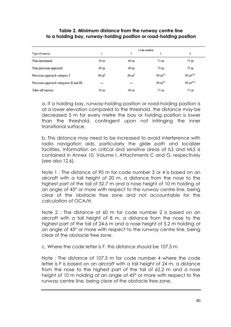
Table 2. Minimum distance from the runway centre line
to a holding bay, runway-holding position or road-holding position
a. If a holding bay, runway-holding position or road-holding position is
at a lower elevation compared to the threshold, the distance may be
decreased 5 m for every metre the bay or holding position is lower
than the threshold, contingent upon not infringing the inner
transitional surface.
b. This distance may need to be increased to avoid interference with
radio navigation aids, particularly the glide path and localizer
facilities. Information on critical and sensitive areas of ILS and MLS is
contained in Annex 10, Volume I, Attachments C and G, respectively
(see also 12.6).
Note 1 : The distance of 90 m for code number 3 or 4 is based on an
aircraft with a tail height of 20 m, a distance from the nose to the
highest part of the tail of 52.7 m and a nose height of 10 m holding at
an angle of 45° or more with respect to the runway centre line, being
clear of the obstacle free zone and not accountable for the
calculation of OCA/H.
Note 2 : The distance of 60 m for code number 2 is based on an
aircraft with a tail height of 8 m, a distance from the nose to the
highest part of the tail of 24.6 m and a nose height of 5.2 m holding at
an angle of 45° or more with respect to the runway centre line, being
clear of the obstacle free zone.
c. Where the code letter is F, this distance should be 107.5 m.
Note : The distance of 107.5 m for code number 4 where the code
letter is F is based on an aircraft with a tail height of 24 m, a distance
from the nose to the highest part of the tail of 62.2 m and a nose
height of 10 m holding at an angle of 45° or more with respect to the
runway centre line, being clear of the obstacle free zone.
41
APRONS
GENERAL
140. Aprons should be provided where necessary to permit the on- and
off-loading of passengers, cargo or mail as well as the servicing of
aircraft without interfering with the aerodrome traffic.
SIZE OF APRONS
141. The total apron area should be adequate to permit expeditious
handling of the aerodrome traffic at its maximum anticipated density.
STRENGTH OF APRONS
142. Each part of an apron should be capable of withstanding the traffic
of the aircraft it is intended to serve, due consideration being given to
the fact that some portions of the apron will be subjected to a higher
density of traffic and, as a result of slow moving or stationary aircraft,
to higher stresses than a runway.
SLOPES ON APRONS
143. Slopes on an apron, including those on an aircraft stand taxilane,
should be sufficient to prevent accumulation of water on the surface
of the apron but should be kept as level as drainage requirements
permit.
144. On an aircraft stand the maximum slope should not exceed 1 per
cent.
42
CLEARANCE DISTANCES ON AIRCRAFT STANDS
145. An aircraft stand should provide the following minimum clearances
between an aircraft using the stand and any adjacent building,
aircraft on another stand and other objects:
Code letter Clearance
A 3 m
B 3 m
C 4.5 m
D 7.5 m
E 7.5 m
F 7.5 m
When special circumstances so warrant, these clearances may be
reduced at a nose-in aircraft stand, where the code letter is D, E or F:
a) between the terminal, including any fixed passenger bridge,
and the nose of an aircraft; and
b) over any portion of the stand provided with azimuth
guidance by a visual docking guidance system.
Note : On aprons, consideration also has to be given to the provision
of service roads and to manoeuvring and storage area for ground
equipment (see the ICAO Aerodrome Design Manual (Doc 9157), Part
2, for guidance on storage of ground equipment).
ISOLATED AIRCRAFT PARKING POSITION
146. An isolated aircraft parking position shall be designated or the
aerodrome control tower shall be advised of an area or areas suitable
for the parking of an aircraft which is known or believed to be the
subject of unlawful interference, or which for other reasons needs
isolation from normal aerodrome activities.
147. The isolated aircraft parking position should be located at the
maximum distance practicable and in any case never less than 100 m
from other parking positions, buildings or public areas, etc. Care
should be taken to ensure that the position is not located over
underground utilities such as gas and aviation fuel and, to the extent
feasible, electrical or communication cables.
43
DEVIATIONS
148. The Department of Civil Aviation shall notify and publish deviation
from any Standards and Recommended Practices contained in ICAO
Annex 14 in the Aeronautical Information Services publications in
compliance to the Article 38 of the Convention on International Civil
Aviation.
149. The Appendices to this Directive shall be taken, construed, read and
be part of this Directive.
DATO’ SRI AZHARUDDIN BIN ABDUL RAHMAN
Director General
Department of Civil Aviation
Malaysia
Dated : 26 April 2016
i
ATTACHMENT A
1. Number, siting and orientation of runways
Siting and orientation of runways
1.1 Many factors should be taken into account in the determination of
the siting and orientation of runways. Without attempting to provide an
exhaustive list of these factors nor an analysis of their effects, it appears
useful to indicate those which most frequently require study. These factors
may be classified under four headings:
1.1.1 Type of operation. Attention should be paid in particular to whether
the aerodrome is to be used in all meteorological conditions or only in visual
meteorological conditions, and whether it is intended for use by day and
night, or only by day.
1.1.2 Climatological conditions. A study of the wind distribution should be
made to determine the usability factor. In this regard, the following
comments should be taken into account:
a) Wind statistics used for the calculation of the usability factor are
normally available in ranges of speed and direction, and the
accuracy of the results obtained depends, to a large extent, on the
assumed distribution of observations within these ranges. In the
absence of any sure information as to the true distribution, it is usual to
assume a uniform distribution since, in relation to the most favourable
runway orientations, this generally results in a slightly conservative
usability factor.
b) The maximum mean crosswind components given in Chapter 3,
3.1.3, refer to normal circumstances. There are some factors which
may require that a reduction of those maximum values be taken into
account at a particular aerodrome. These include:
1) the wide variations which may exist, in handling characteristics
and maximum permissible crosswind components, among diverse
types of aeroplanes (including future types) within each of the
three groups given in 3.1.3;
2) prevalence and nature of gusts;
3) prevalence and nature of turbulence;
4) the availability of a secondary runway;
ii
5) the width of runways;
6) the runway surface conditions — water on the runway
materially reduce the allowable crosswind component; and
7) the strength of the wind associated with the limiting crosswind
component. A study should also be made of the occurrence of
poor visibility and/or low cloud base. Account should be taken of
their frequency as well as the accompanying wind direction and
speed.
1.1.3 Topography of the aerodrome site, its approaches, and surroundings,
particularly:
a) compliance with the obstacle limitation surfaces;
b) current and future land use. The orientation and layout should
be selected so as to protect as far as possible the particularly sensitive
areas such as residential, school and hospital zones from the
discomfort caused by aircraft noise. Detailed information on this topic
is provided in the Airport Planning Manual (Doc 9184), Part 2, and in
Guidance on the Balanced Approach to Aircraft Noise Management
(Doc 9829);
c) current and future runway lengths to be provided;
d) construction costs; and
e) possibility of installing suitable non-visual and visual aids for
approach-to-land.
1.1.4 Air traffic in the vicinity of the aerodrome, particularly:
a) proximity of other aerodromes or ATS routes;
b) traffic density; and
c) air traffic control and missed approach procedures.
iii
Number of runways in each direction
1.2 The number of runways to be provided in each direction depends on
the number of aircraft movements to be
catered to.
2. Clearways and stopways
2.1 The decision to provide a stopway and/or a clearway as an
alternative to an increased length of runway will depend on the physical
characteristics of the area beyond the runway end, and on the operating
performance requirements of the prospective aeroplanes. The runway,
stopway and clearway lengths to be provided are determined by the
aeroplane take-off performance, but a check should also be made of the
landing distance required by the aeroplanes using the runway to ensure
that adequate runway length is provided for landing. The length of a
clearway, however, cannot exceed half the length of take-off run available.
2.2 The aeroplane performance operating limitations require a length
which is enough to ensure that the aeroplane can, after starting a take-off,
either be brought safely to a stop or complete the take-off safely. For the
purpose of discussion it is supposed that the runway, stopway and clearway
lengths provided at the aerodrome are only just adequate for the
aeroplane requiring the longest take-off and accelerate-stop distances,
taking into account its take-off mass, runway characteristics and ambient
atmospheric conditions. Under these circumstances there is, for each take-
off, a speed, called the decision speed; below this speed, the take-off must
be abandoned if an engine fails, while above it the take-off must be
completed. A very long take-off run and take-off distance would be
required to complete a take-off when an engine fails before the decision
speed is reached, because of the insufficient speed and the reduced
power available. There would be no difficulty in stopping in the remaining
accelerate-stop distance available provided action is taken immediately. In
these circumstances the correct course of action would be to abandon the
take-off.
2.3 On the other hand, if an engine fails after the decision speed is
reached, the aeroplane will have sufficient speed and power available to
complete the take-off safely in the remaining take-off distance available.
However, because of the high speed, there would be difficulty in stopping
the aeroplane in the remaining accelerate-stop distance available.
2.4 The decision speed is not a fixed speed for any aeroplane, but can be
selected by the pilot within limits to suit the accelerate-stop and take-off
distance available, aeroplane take-off mass, runway characteristics and
ambient atmospheric conditions at the aerodrome. Normally, a higher
iv
decision speed is selected as the accelerate-stop distance available
increases.
2.5 A variety of combinations of accelerate-stop distances required and
take-off distances required can be obtained to accommodate a particular
aeroplane, taking into account the aeroplane take-off mass, runway
characteristics, and ambient atmospheric conditions. Each combination
requires its particular length of take-off run.
2.6 The most familiar case is where the decision speed is such that the
take-off distance required is equal to the accelerate-stop distance required;
this value is known as the balanced field length. Where stopway and
clearway are not provided, these distances are both equal to the runway
length. However, if landing distance is for the moment ignored, runway is
not essential for the whole of the balanced field length, as the take-off run
required is, of course, less than the balanced field length. The balanced
field length can, therefore, be provided by a runway supplemented by an
equal length of clearway and stopway, instead of wholly as a runway. If the
runway is used for take-off in both directions, an equal length of clearway
and stopway has to be provided at each runway end. The saving in runway
length is, therefore, bought at the cost of a greater overall length.
2.7 In case economic considerations preclude the provision of stopway
and, as a result, only runway and clearway are to be provided, the runway
length (neglecting landing requirements) should be equal to the
accelerate-stop distance required or the take-off run required, whichever is
the greater. The take-off distance available will be the length of the runway
plus the length of clearway.
2.8 The minimum runway length and the maximum stopway or clearway
length to be provided may be determined as follows, from the data in the
aeroplane flight manual for the aeroplane considered to be critical from
the viewpoint of runway length requirements:
a) if a stopway is economically possible, the lengths to be
provided are those for the balanced field length. The runway length is
the take-off run required or the landing distance required, whichever
is the greater. If the accelerate-stop distance required is greater than
the runway length so determined, the excess may be provided as
stopway, usually at each end of the runway. In addition, a clearway
of the same length as the stopway must also be provided;
v
b) if a stopway is not to be provided, the runway length is the
landing distance required, or if it is greater, the accelerate-stop
distance required, which corresponds to the lowest practical value of
the decision speed. The excess of the take-off distance required over
the runway length may be provided as clearway, usually at each end
of the runway.
2.9 In addition to the above consideration, the concept of clearways in
certain circumstances can be applied to a
situation where the take-off distance required for all engines operating
exceeds that required for the engine failure case.
2.10 The economy of a stopway can be entirely lost if, after each usage, it
must be regraded and compacted. Therefore, it should be designed to
withstand at least a certain number of loadings of the aeroplane which the
stopway is intended to serve without inducing structural damage to the
aeroplane.
3. Calculation of declared distances
3.1 The declared distances to be calculated for each runway direction
comprise: the take-off run available (TORA), take-off distance available
(TODA), accelerate-stop distance available (ASDA), and landing distance
available (LDA).
3.2 Where a runway is not provided with a stopway or clearway and the
threshold is located at the extremity of the runway, the four declared
distances should normally be equal to the length of the runway, as shown in
Figure A-1 (A).
3.3 Where a runway is provided with a clearway (CWY), then the TODA
will include the length of clearway, as shown in Figure A-1 (B).
3.4 Where a runway is provided with a stopway (SWY), then the ASDA will
include the length of stopway, as shown in Figure A-1 (C).
3.5 Where a runway has a displaced threshold, then the LDA will be
reduced by the distance the threshold is displaced, as shown in Figure A-1
(D). A displaced threshold affects only the LDA for approaches made to
that threshold; all declared distances for operations in the reciprocal
direction are unaffected.
3.6 Figures A-1 (B) through A-1 (D) illustrate a runway provided with a
clearway or a stopway or having a displaced threshold. Where more than
one of these features exist, then more than one of the declared distances
will be modified — but the modification will follow the same principle
vi
illustrated. An example showing a situation where all these features exist is
shown in Figure A-1 (E).
3.7 A suggested format for providing information on declared distances is
given in Figure A-1 (F). If a runway direction cannot be used for take-off or
landing, or both, because it is operationally forbidden, then this should be
declared and the words “not usable” or the abbreviation “NU” entered.
4. Slopes on a runway
4.1 Distance between slope changes
The following example illustrates how the distance between slope changes
is to be determined (see Figure A-2):
D for a runway where the code number is 3 should be at least:
15 000 (|x – y| + |y – z|) m
|x – y| being the absolute numerical value of x – y
|y – z| being the absolute numerical value of y – z
Assuming x = +0.01
Assuming y = –0.005
Assuming z = +0.005
then |x – y| = 0.015
then |y – z| = 0.01
To comply with the specifications, D should be not less than:
that is, 15 000 (0.015 + 0.01) m,
that is, 15 000 × 0.025 = 375 m
4.2 Consideration of longitudinal and transverse slopes
When a runway is planned that will combine the extreme values for the
slopes and changes in slope permitted under Chapter 3, 3.1.13 to 3.1.19, a
study should be made to ensure that the resulting surface profile will not
hamper the operation of aeroplanes.
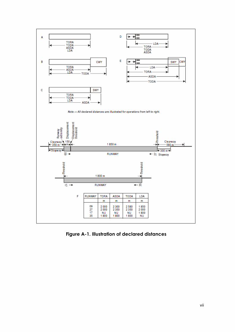
vii
Figure A-1. Illustration of declared distances
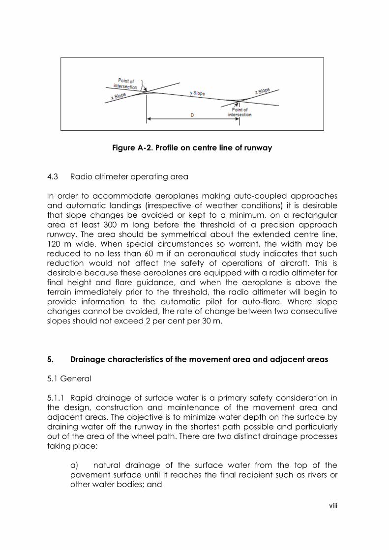
viii
Figure A-2. Profile on centre line of runway
4.3 Radio altimeter operating area
In order to accommodate aeroplanes making auto-coupled approaches
and automatic landings (irrespective of weather conditions) it is desirable
that slope changes be avoided or kept to a minimum, on a rectangular
area at least 300 m long before the threshold of a precision approach
runway. The area should be symmetrical about the extended centre line,
120 m wide. When special circumstances so warrant, the width may be
reduced to no less than 60 m if an aeronautical study indicates that such
reduction would not affect the safety of operations of aircraft. This is
desirable because these aeroplanes are equipped with a radio altimeter for
final height and flare guidance, and when the aeroplane is above the
terrain immediately prior to the threshold, the radio altimeter will begin to
provide information to the automatic pilot for auto-flare. Where slope
changes cannot be avoided, the rate of change between two consecutive
slopes should not exceed 2 per cent per 30 m.
5. Drainage characteristics of the movement area and adjacent areas
5.1 General
5.1.1 Rapid drainage of surface water is a primary safety consideration in
the design, construction and maintenance of the movement area and
adjacent areas. The objective is to minimize water depth on the surface by
draining water off the runway in the shortest path possible and particularly
out of the area of the wheel path. There are two distinct drainage processes
taking place:
a) natural drainage of the surface water from the top of the
pavement surface until it reaches the final recipient such as rivers or
other water bodies; and
ix
b) dynamic drainage of the surface water trapped under a
moving tire until it reaches outside the tire-to-ground contact area.
5.1.2 Both processes can be controlled through:
a) design;
b) construction; and
c) maintenance.
of the pavements in order to prevent accumulation of water on the
pavement surface.
5.2 Design of pavement
5.2.1 Surface drainage is a basic requirement and serves to minimize water
depth on the surface. The objective is to drain water off the runway in the
shortest path. Adequate surface drainage is provided primarily by an
appropriately sloped surface (in both the longitudinal and transverse
directions). The resulting combined longitudinal and transverse slope is the
path for the drainage run-off. This path can be shortened by adding
transverse grooves.
5.2.2 Dynamic drainage is achieved through built-in texture in the
pavement surface. The rolling tire builds up waterpressure and squeezes the
water out the escape channels provided by the texture. The dynamic
drainage of the tire-to-groundcontact area may be improved by adding
transverse grooves provided that they are subject to rigorous maintenance.
5.3 Construction of pavement
5.3.1 Through construction, the drainage characteristics of the surface are
built into the pavement. These surface characteristics are:
a) slopes;
b) texture:
1) microtexture;
2) macrotexture;
x
5.3.2 Slopes for the various parts of the movement area and adjacent parts
are described in Chapter 3 and figures are given as per cent. Further
guidance is given in the Aerodrome Design Manual (Doc 9157), Part 1,
Chapter 5.
5.3.3 Texture in the literature is described as microtexture or macrotexture.
These terms are understood differently in various parts of the aviation
industry.
5.3.4 Microtexture is the texture of the individual stones and is hardly
detectable by the eye. Microtexture is considered a primary component in
skid resistance at slow speeds. On a wet surface at higher speeds a water
film may prevent direct contact between the surface asperities and the tire
due to insufficient drainage from the tire-to-ground contact area.
5.3.5 Microtexture is a built-in quality of the pavement surface. By
specifying crushed material that will withstand polishing microtexture,
drainage of thin waterfilms are ensured for a longer period of time.
Resistance against polishing is expressed in terms of the Polished Stone
Values (PSV) which is in principle a value obtained from a friction
measurement in accordance with international standards. These standards
define the PSV minima that will enable a material with a good microtexture
to be selected.
5.3.6 A major problem with microtexture is that it can change within short
time periods without being easily detected. A typical example of this is the
accumulation of rubber deposits in the touchdown area which will largely
mask microtexture without necessarily reducing macrotexture.
8.3.7 Macrotexture is the texture among the individual stones. This scale of
texture may be judged approximately by the eye. Macrotexture is primarily
created by the size of aggregate used or by surface treatment of the
pavement and is the major factor influencing drainage capacity at high
speeds. Materials shall be selected so as to achieve good macrotexture.
5.3.8 The primary purpose of grooving a runway surface is to enhance
surface drainage. Natural drainage can be slowed down by surface
texture, but grooving can speed up the drainage by providing a shorter
drainage path and increasing the drainage rate.
5.3.9 For measurement of macrotexture, simple methods such as the “sand
and grease patch” methods described in the Airport Services Manual (Doc
9137), Part 2 were developed. These methods were used for the early
research on which current airworthiness requirements are based, which refer
to a classification categorizing macrotexture from A to E. This classification
was developed, using sand or grease patch measuring techniques, and
issued in 1971 by the Engineering Sciences Data Unit (ESDU).
xi
Runway classification based on texture information from ESDU 71026:
Classification Texture depths (mm)
A 0.10 – 0.14
B 0.15 – 0.24
C 0.25 – 0.50
D 0.51 – 1.00
E 1.01 – 2.54
5.3.10 Using this classification, the threshold value between
microtexture and macrotexture is 0.1 mm mean texture depth (MTD).
Related to this scale, the normal wet runway aircraft performance is based
upon texture giving drainage and friction qualities midway between
classification B and C (0.25 mm). Improved drainage through better texture
might qualify for a better aircraft performance class. However such credit
must be in accordance with aeroplane manufacturers’ documentation.
Presently credit is given to grooved or porous friction course runways
following design, construction and maintenance criteria.
5.3.11 For construction, design and maintenance, States use various
international standards. Currently ISO 13473-1: Characterization of
pavement texture by use of surface profiles — Part 1: Determination of
Mean Profile Depth links the volumetric measuring technique with non-
contact profile measuring techniques giving comparable texture values.
These standards describe the threshold value between microtexture and
macrotexture as 0.5 mm. The volumetric method has a validity range from
0.25 to 5 mm MTD. The profilometry method has a validity range from 0 to 5
mm mean profile depth (MPD). The values of MPD and MTD differ due to the
finite size of the glass spheres used in the volumetric technique and because
the MPD is derived from a two-dimensional profile rather than a three-
dimensional surface. Therefore a transformation equation must be
established for the measuring equipment used to relate MPD to MTD.
xii
5.3.12 The ESDU scale groups runway surfaces based on macrotexture
from A through E, where E represents the surface with best dynamic
drainage capacity. The ESDU scale thus reflects the dynamic drainage
characteristics of the pavement. Grooving any of these surfaces enhances
the dynamic drainage capacity. The resulting drainage capacity of the
surface is thus a function of the texture (A through E) and grooving. The
contribution from grooving is a function of the size of the grooves and the
spacing between the grooves. Aerodromes exposed to heavy or torrential
rainfall must ensure that the pavement and adjacent areas have drainage
capability to withstand these rainfalls or put limitations on the use of the
pavements under such extreme situations. These airports should seek to
have the maximum allowable slopes and the use of aggregates providing
good drainage characteristics. They should also consider grooved
pavements in the E classification to ensure that safety is not impaired.
5.4 Maintenance of drainage characteristics of pavement
5.4.1 Macrotexture does not change within a short timespan but
accumulation of rubber can fill up the texture and as such reduce the
drainage capacity, which can result in impaired safety. Furthermore the
runway structure may change over time and give unevenness which results
in ponding after rainfall. Guidance on rubber removal and unevenness can
be found in the Airport Services Manual (Doc 9137), Part 2. Guidance on
methods for improving surface texture can be found in the Aerodrome
Design Manual (Doc 9157), Part 3.
5.4.2 When groovings are used, the condition of the grooves should be
regularly inspected to ensure that no deterioration has occurred and that
the grooves are in good condition. Guidance on maintenance of
pavements is available in the Airport Services Manual (Doc 9137), Part 2 —
Pavement Surface Conditions and Part 9 — Airport Maintenance Practices
and the Aerodrome Design Manual (Doc 9157), Part 2.
5.4.3 The pavement may be shot blasted in order to enhance the
pavement macrotexture.
6. Strips
6.1 Shoulders
xiii
6.1.1 The shoulder of a runway or stopway should be prepared or
constructed so as to minimize any hazard to an aeroplane running off the
runway or stopway. Some guidance is given in the following paragraphs on
certain special problems which may arise, and on the further question of
measures to avoid the ingestion of loose stones or other objects by turbine
engines.
6.1.2 In some cases, the bearing strength of the natural ground in the strip
may be sufficient, without special preparation, to meet the requirements for
shoulders. Where special preparation is necessary, the method used will
depend on local soil conditions and the mass of the aeroplanes the runway
is intended to serve. Soil tests will help in determining the best method of
improvement (e.g. drainage, stabilization, surfacing, light paving).
6.1.3 Attention should also be paid when designing shoulders to prevent
the ingestion of stones or other objects by turbine engines. Similar
considerations apply here to those which are discussed for the margins of
taxiways in the Aerodrome Design Manual (Doc 9157), Part 2, both as to the
special measures which may be necessary and as to the distance over
which such special measures, if required, should be taken.
6.1.4 Where shoulders have been treated specially, either to provide the
required bearing strength or to prevent the presence of stones or debris,
difficulties may arise because of a lack of visual contrast between the
runway surface and that of the adjacent strip. This difficulty can be
overcome either by providing a good visual contrast in the surfacing of the
runway or strip, or by providing a runway side stripe marking.
6.2 Objects on strips
Within the general area of the strip adjacent to the runway, measures
should be taken to prevent an aeroplane’s wheel, when sinking into the
ground, from striking a hard vertical face. Special problems may arise for
runway light fittings or other objects mounted in the strip or at the
intersection with a taxiway or another runway. In the case of construction,
such as runways or taxiways, where the surface must also be flush with the
strip surface, a vertical face can be eliminated by chamfering from the top
of the construction to not less than 30 cm below the strip surface level.
Other objects, the functions of which do not require them to be at surface
level, should be buried to a depth of not less than 30 cm.
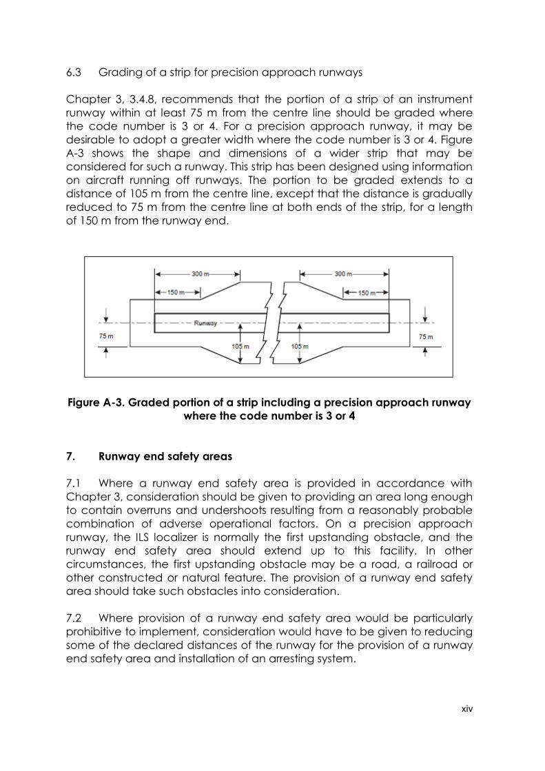
xiv
6.3 Grading of a strip for precision approach runways
Chapter 3, 3.4.8, recommends that the portion of a strip of an instrument
runway within at least 75 m from the centre line should be graded where
the code number is 3 or 4. For a precision approach runway, it may be
desirable to adopt a greater width where the code number is 3 or 4. Figure
A-3 shows the shape and dimensions of a wider strip that may be
considered for such a runway. This strip has been designed using information
on aircraft running off runways. The portion to be graded extends to a
distance of 105 m from the centre line, except that the distance is gradually
reduced to 75 m from the centre line at both ends of the strip, for a length
of 150 m from the runway end.
Figure A-3. Graded portion of a strip including a precision approach runway
where the code number is 3 or 4
7. Runway end safety areas
7.1 Where a runway end safety area is provided in accordance with
Chapter 3, consideration should be given to providing an area long enough
to contain overruns and undershoots resulting from a reasonably probable
combination of adverse operational factors. On a precision approach
runway, the ILS localizer is normally the first upstanding obstacle, and the
runway end safety area should extend up to this facility. In other
circumstances, the first upstanding obstacle may be a road, a railroad or
other constructed or natural feature. The provision of a runway end safety
area should take such obstacles into consideration.
7.2 Where provision of a runway end safety area would be particularly
prohibitive to implement, consideration would have to be given to reducing
some of the declared distances of the runway for the provision of a runway
end safety area and installation of an arresting system.
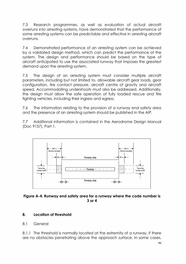
xv
7.3 Research programmes, as well as evaluation of actual aircraft
overruns into arresting systems, have demonstrated that the performance of
some arresting systems can be predictable and effective in arresting aircraft
overruns.
7.4 Demonstrated performance of an arresting system can be achieved
by a validated design method, which can predict the performance of the
system. The design and performance should be based on the type of
aircraft anticipated to use the associated runway that imposes the greatest
demand upon the arresting system.
7.5 The design of an arresting system must consider multiple aircraft
parameters, including but not limited to, allowable aircraft gear loads, gear
configuration, tire contact pressure, aircraft centre of gravity and aircraft
speed. Accommodating undershoots must also be addressed. Additionally,
the design must allow the safe operation of fully loaded rescue and fire
fighting vehicles, including their ingress and egress.
7.6 The information relating to the provision of a runway end safety area
and the presence of an arresting system should be published in the AIP.
7.7 Additional information is contained in the Aerodrome Design Manual
(Doc 9157), Part 1.
Figure A-4. Runway end safety area for a runway where the code number is
3 or 4
8. Location of threshold
8.1 General
8.1.1 The threshold is normally located at the extremity of a runway, if there
are no obstacles penetrating above the approach surface. In some cases,
xvi
however, due to local conditions it may be desirable to displace the
threshold permanently (see below). When studying the location of a
threshold, consideration should also be given to the height of the ILS
reference datum and/or MLS approach reference datum and the
determination of the obstacle clearance limits. (Specifications concerning
the height of the ILS reference datum and MLS approach reference datum
are given in Annex 10, Volume I.)
8.1.2 In determining that no obstacles penetrate above the approach
surface, account should be taken of mobile objects (vehicles on roads,
trains, etc.) at least within that portion of the approach area within 1 200 m
longitudinally from the threshold and of an overall width of not less than 150
m.
8.2 Displaced threshold
8.2.1 If an object extends above the approach surface and the object
cannot be removed, consideration should be given to displacing the
threshold permanently.
8.2.2 To meet the obstacle limitation objectives of Chapter 4, the threshold
should ideally be displaced down the runway for the distance necessary to
provide that the approach surface is cleared of obstacles.
8.2.3 However, displacement of the threshold from the runway extremity will
inevitably cause reduction of the landing distance available, and this may
be of greater operational significance than penetration of the approach
surface by marked and lighted obstacles. A decision to displace the
threshold, and the extent of such displacement, should therefore have
regard to an optimum balance between the considerations of clear
approach surfaces and adequate landing distance. In deciding this
question, account will need to be taken of the types of aeroplanes which
the runway is intended to serve, the limiting visibility and cloud base
conditions under which the runway will be used, the position of the
obstacles in relation to the threshold and extended centre line and, in the
case of a precision approach runway, the significance of the obstacles to
the determination of the obstacle clearance limit.
8.2.4 Notwithstanding the consideration of landing distance available, the
selected position for the threshold should not be such that the obstacle free
surface to the threshold is steeper than 3.3 per cent where the code
number is 4 or steeper than 5 per cent where the code number is 3.
8.2.5 In the event of a threshold being located according to the criteria for
obstacle free surfaces in the preceding paragraph, the obstacle marking
requirements of Chapter 6 should continue to be met in relation to the
displaced threshold.
xvii
8.2.6 Depending on the length of the displacement, the RVR at the
threshold could differ from that at the beginning of the runway for take-offs.
The use of red runway edge lights with photometric intensities lower than the
nominal value of 10 000 cd for white lights increases that phenomenon. The
impact of a displaced threshold on take-off minima should be assessed by
the appropriate authority.
8.2.7 Provisions in Annex 14, Volume I, regarding marking and lighting of
displaced thresholds and some operational recommendations can be
found in 5.2.4.9, 5.2.4.10, 5.3.5.5, 5.3.8.1, 5.3.9.7, 5.3.10.3, 5.3.10.7 and 5.3.12.6.
9. The ACN-PCN method of reporting pavement strength
9.1 Overload operations
9.1.1 Overloading of pavements can result either from loads too large, or
from a substantially increased application rate, or both. Loads larger than
the defined (design or evaluation) load shorten the design life, whilst smaller
loads extend it. With the exception of massive overloading, pavements in
their structural behaviour are not subject to a particular limiting load above
which they suddenly or catastrophically fail. Behaviour is such that a
pavement can sustain a definable load for an expected number of
repetitions during its design life. As a result, occasional minor overloading is
acceptable, when expedient, with only limited loss in pavement life
expectancy and relatively small acceleration of pavement deterioration.
For those operations in which magnitude of overload and/or the frequency
of use do not justify a detailed analysis, the following criteria are suggested:
a) for flexible pavements, occasional movements by aircraft with
ACN not exceeding 10 per cent above the reported PCN should not
adversely affect the pavement;
b) for rigid or composite pavements, in which a rigid pavement
layer provides a primary element of the structure, occasional
movements by aircraft with ACN not exceeding 5 per cent above the
reported PCN should not adversely affect the pavement;
c) if the pavement structure is unknown, the 5 per cent limitation
should apply; and
d) the annual number of overload movements should not exceed
approximately 5 per cent of the total annual aircraft movements.
9.1.2 Such overload movements should not normally be permitted on
pavements exhibiting signs of distress or failure. Furthermore, overloading
xviii
should be avoided during any periods of thaw following frost penetration, or
when the strength of the pavement or its subgrade could be weakened by
water. Where overload operations are conducted, the appropriate
authority should review the relevant pavement condition regularly, and
should also review the criteria for overload operations periodically since
excessive repetition of overloads can cause severe shortening of pavement
life or require major rehabilitation of pavement.
9.2 ACNs for several aircraft types
For convenience, several aircraft types currently in use have been
evaluated on rigid and flexible pavements founded on the four subgrade
strength categories in Chapter 2, 2.6.6 b), and the results tabulated in the
Aerodrome Design Manual (Doc 9157), Part 3.