AERO OCT2010
32
QTR_03 10 A QUARTERLY PUBLICATION BOEING.COM/COMMERCIAL/ AEROMAGAZINE Serving You Better 747-8 Offers Operational Improvements and Cross-Model Commonality 747-8 at Existing Airports Improving Fleet Reliability Understanding Tools and Equipment Equivalency
-
Upload
anarayan707 -
Category
Documents
-
view
139 -
download
5
Transcript of AERO OCT2010
QTR_03
1 0A QUARTERLY PUBLICATION BOEING.COM/COMMERCIAL/ AEROMAGAZINE
Serving You Better
747-8 Offers Operational Improvements and Cross-Model Commonality
747-8 at Existing Airports
Improving Fleet Reliability
Understanding Tools and Equipment Equivalency

Cover photo: 777 Tail.
AERO
01WWW.BOEING.COM/COMMERCIAL/AEROMAGAZINE Issue 39_Quarter 03!| 2010
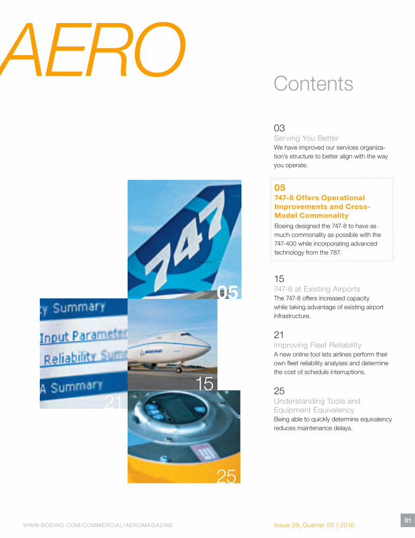
Contents
03Serving You BetterWe have improved our services organiza-tion’s structure to better align with the way you operate.
05747-8 Offers Operational Improvements and Cross-Model CommonalityBoeing designed the 747-8 to have as much commonality as possible with the 747-400 while incorporating advanced technology from the 787.
15747-8 at Existing Airports The 747-8 offers increased capacity while taking advantage of existing airport infrastructure.
21Improving Fleet ReliabilityA new online tool lets airlines perform their own fleet reliability analyses and determine the cost of schedule interruptions.
25Understanding Tools and Equipment EquivalencyBeing able to quickly determine equivalency reduces maintenance delays.
25
05
1521
02AERO QUARTERLY QTR_03 | 10
Editorial Board
Gary Bartz, Frank Billand, Richard Breuhaus, Tom Dodt, Justin Hale,
Darrell!Hokuf, Al John, Doug!Lane, Jill Langer, Duke McMillin, David Presuhn,
Wade Price, Bob!Rakestraw, Frank!Santoni, Jerome Schmelzer
Technical Review Committee
Gary Bartz, Frank Billand, Richard Breuhaus, David Carbaugh, Tom Dodt,
Justin!Hale, Darrell Hokuf, Al John, Doug Lane, Jill!Langer, Duke McMillin,
David Palmer, David Presuhn, Wade Price, Jerome Schmelzer, William Tsai
AERO Online
www.boeing.com/commercial/aeromagazine
AERO magazine is published quarterly by Boeing Commercial Airplanes and is distributed at no cost to operators of Boeing commercial airplanes. AERO provides operators with supplemental technical information to promote continuous safety and efficiency in their daily fleet operations.
The Boeing Company supports operators during the life of each Boeing commercial airplane. Support includes stationing Field Service representatives in more than 60!countries, furnishing spare parts and engineering support, training flight crews and maintenance personnel, and providing operations and maintenance publications.
Boeing continually communicates with operators through such vehicles as technical meetings, service letters, and service bulletins. This assists operators in addressing regulatory requirements and Air Transport Association specifications.
Copyright © 2010!The Boeing Company
Correction: In the second quarter issue of AERO, there was an error in the table on page 27 labeled “Fuel Savings Estimates for Delayed-Flaps Approach Procedure.” For the 747-400 CF6-80C2B1F, the values for 30!flaps are “550!(250)” and “60!(27).” We regret any inconvenience to our readers.
Information published in AERO magazine is intended to be accurate and authoritative. However, no material should be considered regulatory-approved unless specifically stated. Airline personnel are advised that their company’s policy may differ from or conflict with information in this publication. Customer airlines may republish articles from AERO without permission if for distribution only within their own organizations. They thereby assume responsibility for the current accuracy of the republished material. All others must obtain written permission from Boeing before reprinting any AERO article.
Print copies of AERO are not available by subscription, but the publication may be viewed on the Web at www.boeing.com/commercial/aeromagazine.
Please send address changes to [email protected]. Please send all other communications to AERO!Magazine, Boeing Commercial Airplanes, P.O. Box 3707, MC!21-72, Seattle, Washington, 98124-2207, USA. E-mail: [email protected]
AERO is printed on Forest Stewardship Council Certified paper.
AEROPublisher
Shannon Frew
Editorial director
Jill Langer
Editor-in-chief
Jim Lombardo
Design
Methodologie
Writer
Jeff Fraga
Distribution manager
Nanci Moultrie
Cover photography
Jeff Corwin
Printer
ColorGraphics
Web site design
Methodologie

03WWW.BOEING.COM/COMMERCIAL/AEROMAGAZINE
Aligning Our Business to Better Meet Your NeedsTo ensure that we have the best Boeing Commercial Aviation Services organization to serve you — our valued customers — we have improved our organizational structure to better align with the way you operate.
We have reorganized into four business units:
Material Services — This business aligns with your purchasing organization. It includes spare parts and services such as Component Services and Landing Gear Exchange programs. It also includes subsidiary Aviall, which distributes original-equipment-manufacturer parts and supply- chain management services. Vice President Dale Wilkinson leads this group.
Fleet Services — This business unit works with your engineering and maintenance departments. It includes freighter conver sions, airplane modifications, airplane-on-ground response teams, and aviation information solutions, such as Airplane Health Manage-ment and Maintenance Performance Toolbox. Also part of this business are Fleet Management/GoldCare; joint ventures Boeing Shanghai, Aviation Partners Boeing, and TAECO; and Technical Customer
Support, which provides maintenance, service, and out-of-production engineering and field service support. Vice President Dennis Floyd leads Fleet Services.
Flight Services — This business aligns with your flight operations group. It includes flight, maintenance, and cabin safety training; flight operations support; and simulator services. It also includes sub si-diary Jeppesen, which provides navigation and operations services for all segments of aviation. In addition, our Aviation Infra-structure group is an integral part of this business. Vice President Sherry Carbary leads Flight Services.
Information Services — This newly created business unit works with your information technology organization. It includes the MyBoeingFleet.com Web portal, our e-Business organization, and our sub-sidiaries Inventory Locator Services,
Continental DataGraphics, and AeroInfo Systems. Our objective in forming this business unit is to bring system technology and online access to Boeing information, products, and services. Vice President Per Norén leads this new group.
We are very excited about taking these important steps to bring you stronger sup-port and services. Please do not hesitate to contact us if you have any questions.
Thank you for operating Boeing airplanes.
LOU MANCINI
Senior Vice President, Boeing Commercial Aviation Services
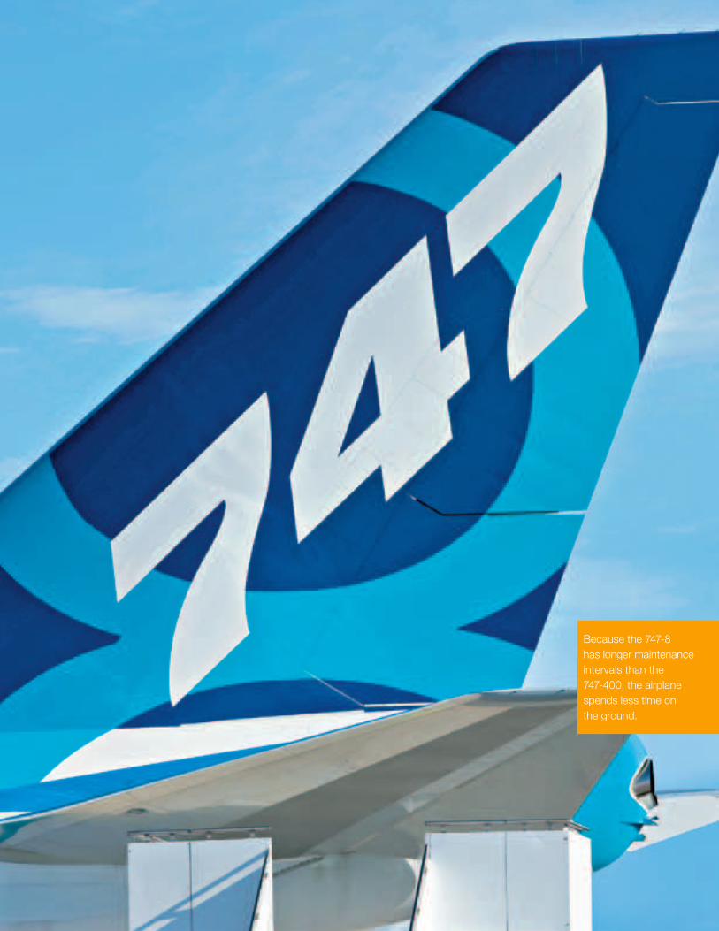
Because the 747-8 has longer maintenance intervals than the 747-400, the airplane spends less time on the ground.
05WWW.BOEING.COM/COMMERCIAL/AEROMAGAZINE
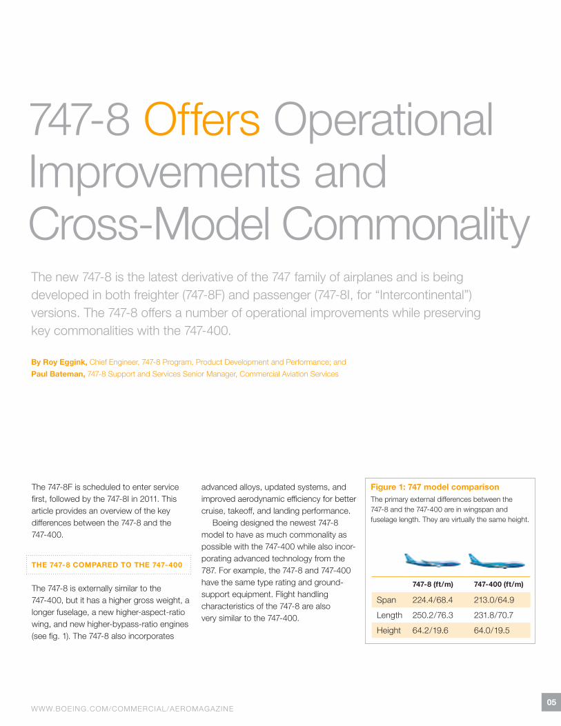
747-8 Offers Operational Improvements and Cross-Model CommonalityThe new 747-8 is the latest derivative of the 747!family of airplanes and is being developed in both freighter (747-8F) and passenger (747-8I, for “Intercontinental”) versions. The 747-8 offers a number of operational improvements while preserving key commonalities with the 747-400.
By Roy Eggink, Chief Engineer, 747-8 Program, Product Development and Performance; and Paul Bateman, 747-8 Support and Services Senior Manager, Commercial Aviation Services
The 747-8F is scheduled to enter service first, followed by the 747-8I in 2011. This article provides an overview of the key differences between the 747-8 and the 747-400.
THE 747-8 COMPARED TO THE 747-400
The 747-8 is externally similar to the 747-400, but it has a higher gross weight, a longer fuselage, a new higher-aspect-ratio wing, and new higher-bypass-ratio engines (see fig.!1). The 747-8 also incorporates
advanced alloys, updated systems, and improved aerodynamic efficiency for better cruise, takeoff, and landing performance.
Boeing designed the newest 747-8 model to have as much commonality as possible with the 747-400 while also incor-porating advanced technology from the 787. For example, the 747-8 and 747-400 have the same type rating and ground-support equipment. Flight handling characteristics of the 747-8 are also very similar to the 747-400.
Figure 1: 747!model comparisonThe primary external differences between the 747-8 and the 747-400 are in wingspan and fuselage length. They are virtually the same height.
747-8 (ft / m) 747-400 (ft / m)
Span 224.4 / 68.4 213.0 / 64.9
Length 250.2 / 76.3 231.8 / 70.7
Height 64.2 / 19.6 64.0 / 19.5
06AERO QUARTERLY QTR_03 | 10
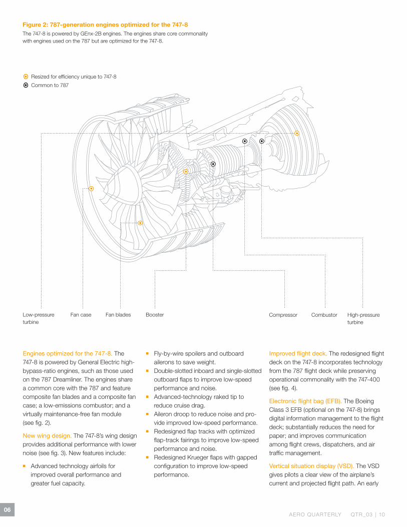
Figure 2: 787-generation engines optimized for the 747-8The 747-8 is powered by GEnx-2B engines. The engines share core commonality with engines used on the 787!but are optimized for the 747-8.
Common to 787
Resized for efficiency unique to 747-8
Fan case Fan blades Booster Compressor Combustor High-pressure turbine
Low-pressure turbine
Engines optimized for the 747-8. The 747-8 is powered by General Electric high-bypass-ratio engines, such as those used on the 787!Dreamliner. The engines share a common core with the 787 and feature composite fan blades and a composite fan case; a low-emissions combustor; and a virtually maintenance-free fan module (see!fig.!2).
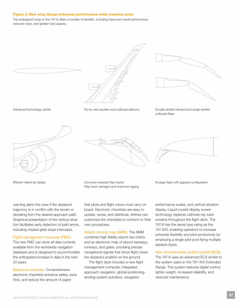
New wing design. The 747-8’s wing design provides additional performance with lower noise (see fig.!3). New features include:
! Advanced technology airfoils for improved overall performance and greater fuel capacity.
! Fly-by-wire spoilers and outboard ailerons to save weight.
! Double-slotted inboard and single-slotted outboard flaps to improve low-speed performance and noise.
! Advanced-technology raked tip to reduce cruise drag.
! Aileron droop to reduce noise and pro-vide improved low-speed performance.
! Redesigned flap tracks with optimized flap-track fairings to improve low-speed performance and noise.
! Redesigned Krueger flaps with gapped configuration to improve low-speed performance.
Improved !ight deck. The redesigned flight deck on the 747-8 incorporates technology from the 787!flight deck while preserving operational commonality with the 747-400 (see fig.!4).
Electronic !ight bag (EFB). The Boeing Class 3!EFB (optional on the 747-8) brings digital information management to the flight deck; substantially reduces the need for paper; and improves communication among flight crews, dispatchers, and air traffic management.
Vertical situation display (VSD). The VSD gives pilots a clear view of the airplane’s current and projected flight path. An early
07WWW.BOEING.COM/COMMERCIAL/AEROMAGAZINE
Advanced technology airfoils Fly-by-wire spoilers and outboard ailerons Double-slotted inboard and single-slotted outboard flaps
Efficient raked-tip design Corrosion-resistant flap tracks Flap track carriages and improved rigging
Krueger flaps with gapped configuration
Figure 3: New wing design enhances performance while lowering noiseThe redesigned wing on the 747-8 offers a number of benefits, including improved overall performance, reduced noise, and greater fuel capacity.
warning alerts the crew if the airplane’s trajectory is in conflict with the terrain or deviating from the desired approach path. Graphical presentation of the vertical situa-tion facilitates early detection of path errors, including missed glide slope intercepts.
Flight management computer (FMC). The new FMC can store all data currently available from the worldwide navigation database and is designed to accommodate the anticipated increase in data in the next 20!years.
Electronic checklist. Comprehensive electronic checklists enhance safety, save time, and reduce the amount of paper
that pilots and flight crews must carry on board. Electronic checklists are easy to update, revise, and distribute. Airlines can customize the checklists to conform to their own procedures.
Airport moving map (AMM). The AMM combines high-fidelity airport taxi charts and an electronic map of airport taxiways, runways, and gates, providing precise navigational signals that show flight crews the airplane’s position on the ground.
The flight deck includes a new flight management computer, integrated approach navigation, global-positioning-landing-system autoland, navigation
performance scales, and vertical situation display. Liquid-crystal-display screen technology replaces cathode-ray-tube screens throughout the flight deck. The 747-8 has the same type rating as the 747-400, enabling operators to increase schedule flexibility and pilot productivity by employing a single-pilot pool flying multiple airplane types.
New environmental control system (ECS). The 747-8 uses an advanced ECS similar to the system used on the 767-400 Extended Range. This system features digital control, lighter weight, increased reliability, and reduced maintenance.

08AERO QUARTERLY QTR_03 | 10
Figure 4: 747-8 flight deck The 747-8 flight deck incorporates new features such as multifunction displays, electronic flight bag provisions, electronic checklist, and tabber control device for the flight management computer.
1. Electronic Flight Bag 2. Vertical Situation Display 3. Flight Management Computer 4. Electronic Checklist 5. Airport Moving Map
1
3
42

09WWW.BOEING.COM/COMMERCIAL/AEROMAGAZINE
5
10AERO QUARTERLY QTR_03 | 10
Pay
load
(1,0
00 lb
)
330
275
220
165
110
55
3 4 5 6 7 8 9 10
Range (1,000 nmi)
Pay
load
(1,0
00 lb
)
80
70
60
50
40
30
20
10
05 6 7 8 9 10
Range (1,000 nmi)
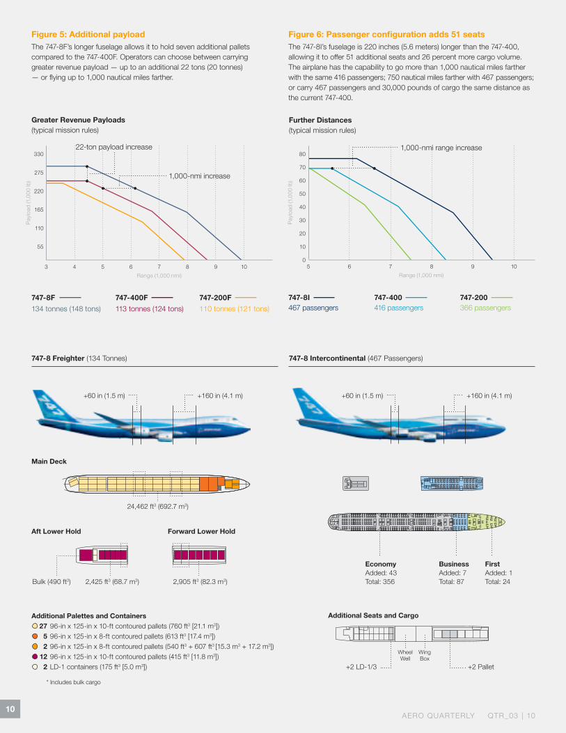
747-8F 134 tonnes (148 tons)
747-400F 113 tonnes (124 tons)
747-200F 110 tonnes (121 tons)
Greater Revenue Payloads (typical mission rules)
747-8 Freighter (134 Tonnes)
* Includes bulk cargo
Main Deck
Forward Lower Hold
Additional Palettes and Containers 27 96-in x 125-in x 10-ft contoured pallets (760 ft3 [21.1 m3]) 5 96-in x 125-in x 8-ft contoured pallets (613 ft3 [17.4 m3]) 2 96-in x 125-in x 8-ft contoured pallets (540 ft3 + 607 ft3 [15.3 m3 + 17.2 m3]) 12 96-in x 125-in x 10-ft contoured pallets (415 ft3 [11.8 m3]) 2 LD-1 containers (175 ft3 [5.0 m3])
2,905 ft3 (82.3 m3)2,425 ft3 (68.7 m3)
24,462 ft3 (692.7 m3)
Bulk (490 ft3)
Aft Lower Hold
747-8 Intercontinental (467 Passengers)
Figure 5: Additional payload The 747-8F’s longer fuselage allows it to hold seven additional pallets compared to the 747-400F. Operators can choose between carrying greater revenue payload — up to an additional 22!tons (20!tonnes) — or flying up to 1,000!nautical miles farther.
Figure 6: Passenger configuration adds 51!seatsThe 747-8I’s fuselage is 220!inches (5.6!meters) longer than the 747-400, allowing it to offer 51!additional seats and 26!percent more cargo volume. The airplane has the capability to go more than 1,000!nautical miles farther with the same 416!passengers; 750!nautical miles farther with 467!passengers; or carry 467!passengers and 30,000!pounds of cargo the same distance as the current 747-400.
Further Distances (typical mission rules)
747-8I 467 passengers
747-400 416 passengers
747-200 366 passengers
Additional Seats and Cargo
+160 in (4.1 m)+60 in (1.5 m) +160 in (4.1 m)+60 in (1.5 m)
+2 Pallet
Wheel Well
Wing Box
+2 LD-1/3
BusinessAdded: 7Total: 87
FirstAdded: 1Total: 24
EconomyAdded: 43Total: 356
22-ton payload increase
1,000-nmi increase
1,000-nmi range increase
11WWW.BOEING.COM/COMMERCIAL/AEROMAGAZINE
More cargo volume. With a fuselage that’s 18.4!feet (5.6!meters) longer than the 747-400F, the 747-8F has 16!percent more revenue cargo volume. It retains the 747-400’s nose-door loading capability, industry-standard 10-foot-high (3!meter) pallets, and cargo-density capability of 10.3!pounds per cubic foot (165!kilograms per cubic meter). The 747-8F has a maximum structural payload capacity of 148!tons (134!tonnes) and, with 4,245!cubic feet (120!cubic meters) greater volume than the 747-400F, the airplane can accom modate four additional main-deck pallets and three additional lower-hold pallets (see!fig.!5).
While the 747-8F can carry more cargo than the 747-400F, it also has an improved cargo handling system that is lighter, more reliable, and provides more flexibility, making it more efficient to load and unload the airplane.
The 747-8F has nearly equivalent trip costs and 16!percent lower ton-mile costs than the 747-400F. The new 747-8F airplane offers a range of 4,390!nautical miles (8,130!kilometers) at maximum structural payload.
Passenger version. The 747-8I offers 51!additional seats and 26!percent more cargo volume than the 747-400, offering
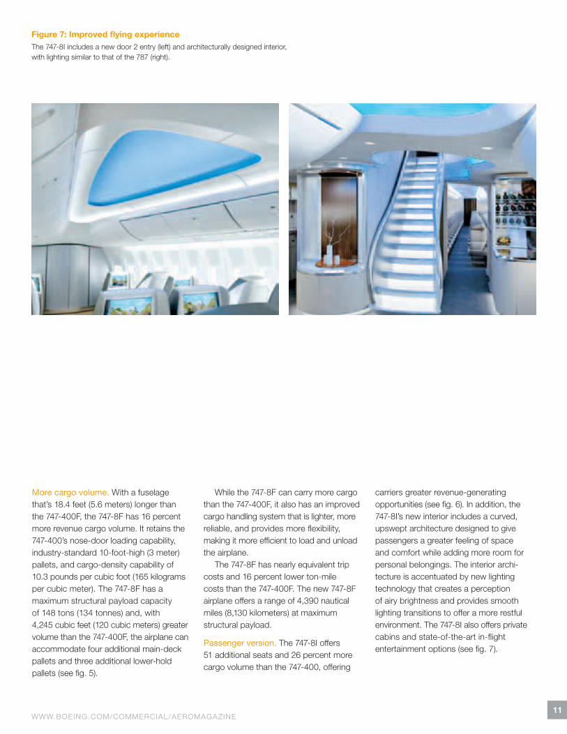
carriers greater revenue-generating opportunities (see fig.!6). In addition, the 747-8I’s new interior includes a curved, upswept architecture designed to give passengers a greater feeling of space and comfort while adding more room for personal belongings. The interior archi-tecture is accentuated by new lighting technology that creates a perception of airy brightness and provides smooth lighting transitions to offer a more restful environ ment. The 747-8I also offers private cabins and state-of-the-art in-flight entertainment options (see fig.!7).
Figure 7: Improved flying experienceThe 747-8I includes a new door 2!entry (left) and architecturally designed interior, with lighting similar to that of the 787!(right).
12AERO QUARTERLY QTR_03 | 10
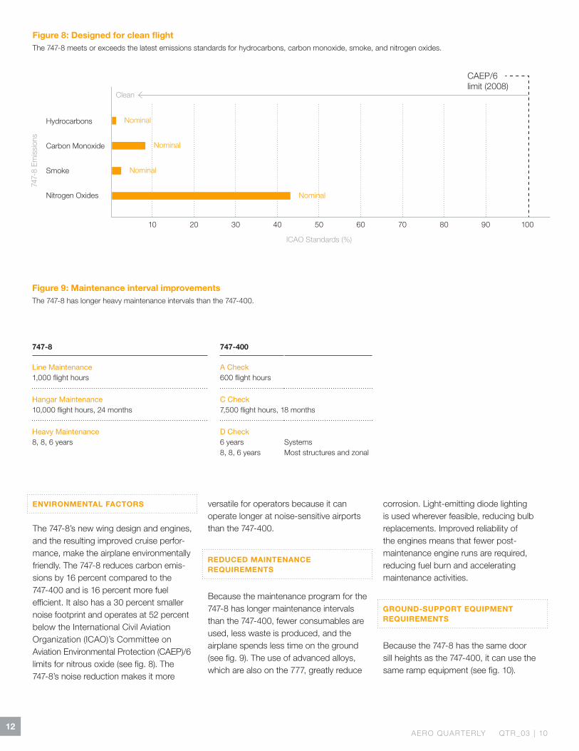
Figure 9: Maintenance interval improvements The 747-8 has longer heavy maintenance intervals than the 747-400.
Need clarification for lower right table. We’re not sure how the text in the two columns relate to each other; will it make sense to readers?
ENVIRONMENTAL FACTORS
The 747-8’s new wing design and engines, and the resulting improved cruise perfor-mance, make the airplane environ mentally friendly. The 747-8 reduces carbon emis-sions by 16!percent compared to the 747-400 and is 16!percent more fuel efficient. It also has a 30!percent smaller noise footprint and operates at 52!percent below the International Civil Aviation Organization (ICAO)’s Committee on Aviation Environmental Protection (CAEP)/6 limits for nitrous oxide (see fig.!8). The 747-8’s noise reduction makes it more
versatile for operators because it can operate longer at noise-sensitive airports than the 747-400.
REDUCED MAINTENANCE REQUIREMENTS
Because the maintenance program for the 747-8 has longer maintenance intervals than the 747-400, fewer consumables are used, less waste is produced, and the airplane spends less time on the ground (see fig.!9). The use of advanced alloys, which are also on the 777, greatly reduce
corrosion. Light-emitting diode lighting is used wherever feasible, reducing bulb replacements. Improved reliability of the engines means that fewer post-maintenance engine runs are required, reducing fuel burn and accelerating maintenance activities.
GROUND-SUPPORT EQUIPMENT REQUIREMENTS
Because the 747-8 has the same door sill heights as the 747-400, it can use the same ramp equipment (see fig.!10).
Clean
Nominal
Nominal
Nominal
Nominal
Figure 8: Designed for clean flightThe 747-8 meets or exceeds the latest emissions standards for hydrocarbons, carbon monoxide, smoke, and nitrogen oxides.
747-8 747-400
Line Maintenance 1,000 flight hours
A Check 600 flight hours
Hangar Maintenance 10,000 flight hours, 24 months
C Check 7,500 flight hours, 18 months
Heavy Maintenance 8, 8, 6 years
D Check 6 years8, 8, 6 years
Systems Most structures and zonal
747-
8 Em
issi
ons
Hydrocarbons
Carbon Monoxide
Smoke
Nitrogen Oxides
10 20 30 40 50 60 70 80 90 100
ICAO Standards (%)
CAEP/6 limit (2008)
13WWW.BOEING.COM/COMMERCIAL/AEROMAGAZINE
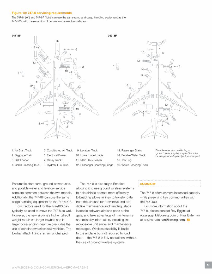
Figure 10: 747-8 servicing requirementsThe 747-8I (left) and 747-8F (right) can use the same ramp and cargo handling equipment as the 747-400, with the exception of certain towbarless tow vehicles.
Pneumatic start carts, ground power units, and potable water and lavatory service carts are common between the two models. Additionally, the 747-8F can use the same cargo handling equipment as the 747-400F.
Tow tractors used for the 747-400 can typically be used to move the 747-8 as well. However, the new airplane’s higher takeoff weight requires a larger towbar, and its larger nose-landing-gear tire precludes the use of certain towbarless tow vehicles. The towbar attach fittings remain unchanged.
The 747-8 is also fully e-Enabled, allowing it to use ground wireless systems to help airlines operate more efficiently. E-Enabling allows airlines to transfer data from the airplane for preventive and pre-dictive maintenance and trending; stage loadable software airplane parts at the gate; and take advantage of maintenance and reliability information, including line-replaceable unit errors and maintenance messages. Wireless capability is basic to the airplane but not required to load data!— the 747-8 is fully operational with out the use of ground wireless systems.
SUMMARY
The 747-8 offers carriers increased capacity while preserving key commonalities with the 747-400.
For more information about the 747-8, please contact Roy Eggink at [email protected] or Paul Bateman at [email protected].
1. Air Start Truck
2. Baggage Train
3. Belt Loader
4. Cabin Cleaning Truck
5. Conditioned Air Truck
6. Electrical Power
7. Galley Truck
8. Hydrant Fuel Truck
9. Lavatory Truck
10. Lower Lobe Loader
11. Main Deck Loader
12. Passenger Boarding Bridge
13. Passenger Stairs
14. Potable Water Truck
15. Tow Tug
16. Waste Servicing Truck
* Potable water, air conditioning, or ground power may be supplied from the passenger boarding bridge if so equipped.
747-8I* 747-8F
10 10
1011
10
11
13
12
12
66
7
7
8
4
33
5
1
1
88
9
7
5
14
15
16
14
2 2
22
22
2
2
14AERO QUARTERLY QTR_03 | 10
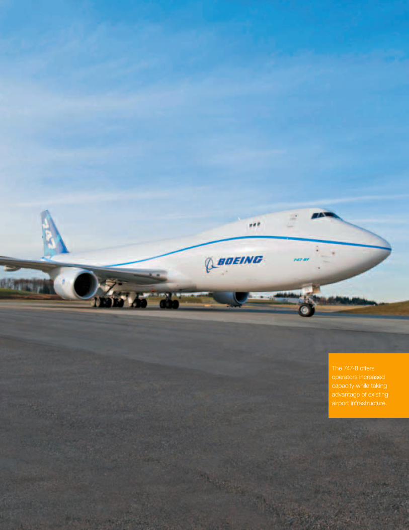
The 747-8 offers operators increased capacity while taking advantage of existing airport infrastructure.
15WWW.BOEING.COM/COMMERCIAL/AEROMAGAZINE
Operating the 747-8 at Existing Airports Today’s major airports are designed largely based on the critical dimensions of the 747-400. Because the 747-8 retains many of the 747-400’s key dimensions (e.g., main gear span, engine span, and tail height) and performance characteristics, many of the airfield elements at existing airports — such as runway and taxiway widths — should be compatible with the 747-8.
By Karen Dix-Colony, Product Development Lead Engineer, Airport Technology; and Brad Bachtel, Manager, Airport Technology
In the United States, the Federal Aviation Administration (FAA) has already approved the 747-8 for operations at airports with parallel runway and taxiway centerline distances that are the same as those required for the 747-400, which are aspects of airport compatibility. Boeing is working with the FAA, Civil Aviation Authorities (CAAs), and airports around the world to agree on clearances that would allow the 747-8 to operate safely and economically at today’s 747-400 airports.
This article provides an overview of airport design codes and how Boeing is using existing FAA and International Civil Aviation Organization (ICAO) processes
to work with the world’s CAAs to demon-strate that the 747-8 airplane can operate safely on 747-400 taxiways, taxilanes, and runways.
AIRPLANE DESIGN
Airplane dimensions were considered during the 747-8 design process so it could operate in today’s 747-400 airports safely and efficiently. It has the same exterior dimensions as the 747-400, except for an 11.4-foot (3.5-meter) wider wingspan (fully fueled) and 18.4-foot (5.6-meter) greater length. It builds on the current 747’s capability to fly into major airports world-
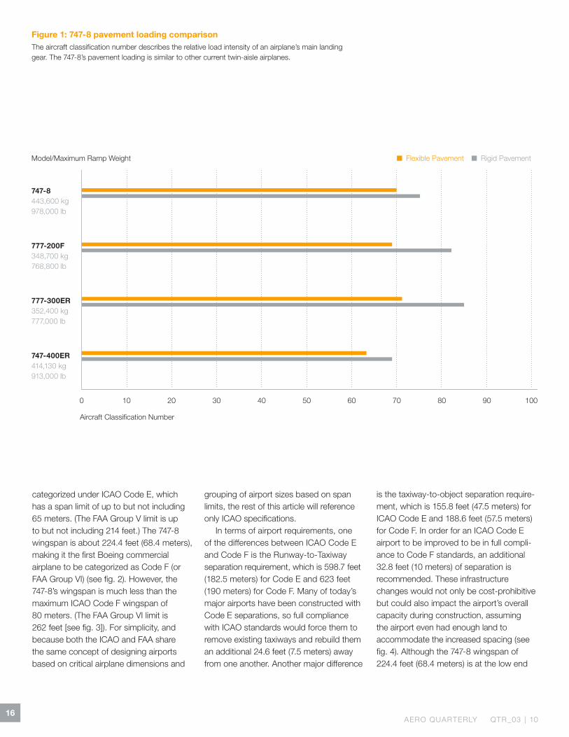
wide, using the same pilot type ratings, and similar aircraft services and ground-support equipment (for specific details, please see Section 5 of the airplane plan-ning manual located at http://www.boeing.com/commercial/airports/747.htm). The airplane’s higher gross weight increases the pave ment loading approximately 18!percent but is still comparable to today’s twin-aisle airplanes (see fig.!1).
AIRPORT DESIGN CODES
ICAO airplane design codes (or groups, in the case of the FAA) are based primarily on wingspan. The legacy 747!family has been
16AERO QUARTERLY QTR_03 | 10
Figure 1: 747-8 pavement loading comparisonThe aircraft classification number describes the relative load intensity of an airplane’s main landing gear. The 747-8’s pavement loading is similar to other current twin-aisle airplanes.
Model/Maximum Ramp Weight ! Flexible Pavement ! Rigid Pavement
747-8 443,600 kg 978,000 lb
777-200F 348,700 kg 768,800 lb
777-300ER 352,400 kg 777,000 lb
747-400ER 414,130 kg 913,000 lb
Aircraft Classification Number
categorized under ICAO Code E, which has a span limit of up to but not including 65!meters. (The FAA Group V limit is up to but not including 214!feet.) The 747-8 wingspan is about 224.4!feet (68.4!meters), making it the first Boeing commercial airplane to be categorized as Code F (or FAA Group VI) (see fig.!2). However, the 747-8’s wingspan is much less than the maximum ICAO Code F wingspan of 80!meters. (The FAA Group VI limit is 262!feet [see fig.!3]). For simplicity, and because both the ICAO and FAA share the same concept of designing airports based on critical airplane dimensions and
grouping of airport sizes based on span limits, the rest of this article will reference only ICAO specifications.
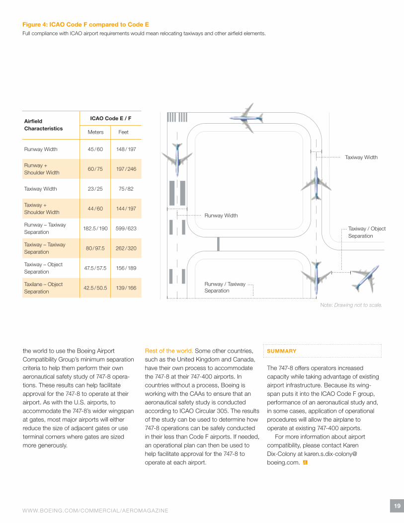
In terms of airport requirements, one of the differences between ICAO Code E and Code F is the Runway-to-Taxiway separation requirement, which is 598.7!feet (182.5!meters) for Code E and 623!feet (190!meters) for Code F. Many of today’s major airports have been constructed with Code E separations, so full compliance with ICAO standards would force them to remove existing taxiways and rebuild them an additional 24.6!feet (7.5!meters) away from one another. Another major difference
is the taxiway-to-object separation require-ment, which is 155.8!feet (47.5!meters) for ICAO Code E and 188.6!feet (57.5 meters) for Code F. In order for an ICAO Code E airport to be improved to be in full compli-ance to Code!F standards, an additional 32.8!feet (10!meters) of separation is recommended. These infrastructure changes would not only be cost-prohibitive but could also impact the airport’s overall capacity during construction, assuming the airport even had enough land to accommodate the increased spacing (see fig.!4). Although the 747-8 wingspan of 224.4!feet (68.4!meters) is at the low end
0 10 20 40 50 60 70 80 90 10030
17WWW.BOEING.COM/COMMERCIAL/AEROMAGAZINE
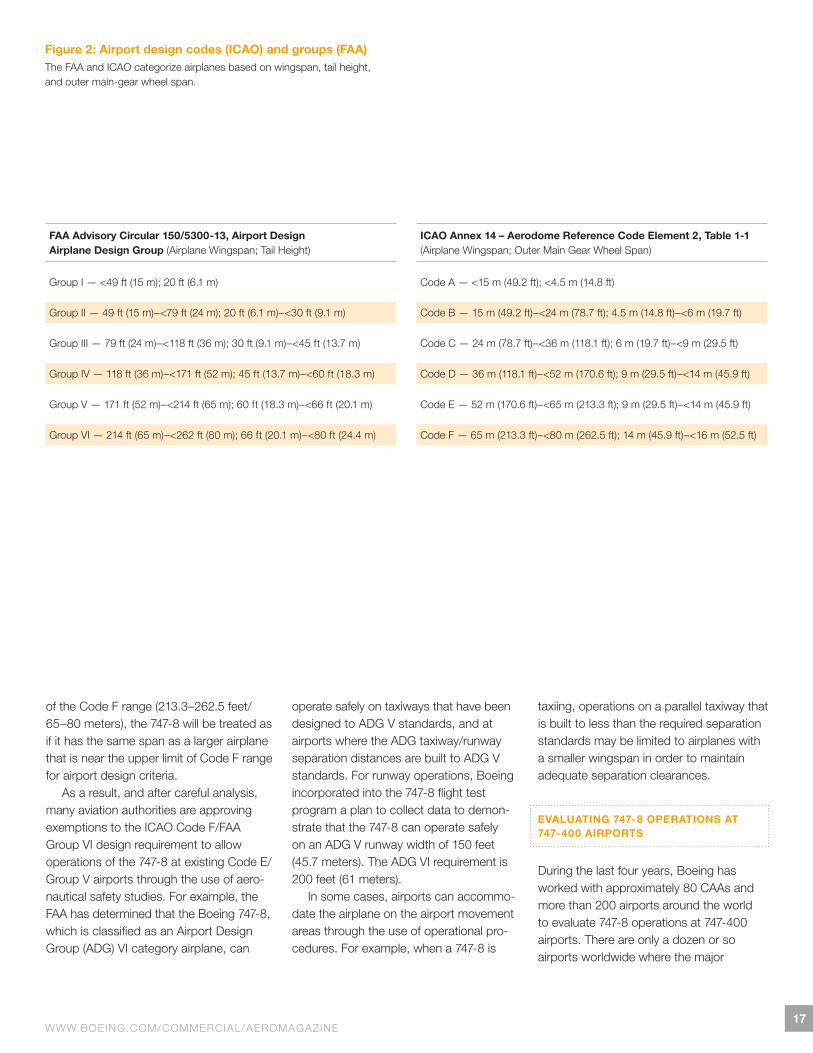
Figure 2: Airport design codes (ICAO) and groups (FAA)The FAA and ICAO categorize airplanes based on wingspan, tail height, and outer main-gear wheel span.
of the Code!F range (213.3–262.5!feet/ 65–80!meters), the 747-8 will be treated as if it has the same span as a larger airplane that is near the upper limit of Code!F range for airport design criteria.
As a result, and after careful analysis, many aviation authorities are approving exemptions to the ICAO Code!F/FAA Group!VI design requirement to allow operations of the 747-8 at existing Code!E/Group!V airports through the use of aero-nautical safety studies. For example, the FAA has determined that the Boeing 747-8, which is classified as an Airport Design Group (ADG) VI category airplane, can
operate safely on taxiways that have been designed to ADG V standards, and at airports where the ADG taxiway/runway separation distances are built to ADG V standards. For runway operations, Boeing incorporated into the 747-8 flight test program a plan to collect data to demon-strate that the 747-8 can operate safely on an ADG V runway width of 150!feet (45.7!meters). The ADG VI requirement is 200!feet (61!meters).
In some cases, airports can accommo-date the airplane on the airport movement areas through the use of operational pro-cedures. For example, when a 747-8 is
taxiing, operations on a parallel taxiway that is built to less than the required separation standards may be limited to airplanes with a smaller wingspan in order to maintain adequate separation clearances.
EVALUATING 747-8 OPERATIONS AT 747-400 AIRPORTS
During the last four years, Boeing has worked with approximately 80!CAAs and more than 200!airports around the world to evaluate 747-8 operations at 747-400 airports. There are only a dozen or so airports worldwide where the major
FAA Advisory Circular 150/5300-13, Airport Design Airplane Design Group (Airplane Wingspan; Tail Height)
ICAO Annex 14 – Aerodome Reference Code Element 2, Table 1-1 (Airplane Wingspan; Outer Main Gear Wheel Span)
Group I — <49 ft (15 m); 20 ft (6.1 m) Code A — <15 m (49.2 ft); <4.5 m (14.8 ft)
Group II — 49 ft (15 m) – <79 ft (24 m); 20 ft (6.1 m) – <30 ft (9.1 m) Code B — 15 m (49.2 ft) – <24 m (78.7 ft); 4.5 m (14.8 ft) – <6 m (19.7 ft)
Group III — 79 ft (24 m) – <118 ft (36 m); 30 ft (9.1 m) – <45 ft (13.7 m) Code C — 24 m (78.7 ft) – <36 m (118.1 ft); 6 m (19.7 ft) – <9 m (29.5 ft)
Group IV — 118 ft (36 m) – <171 ft (52 m); 45 ft (13.7 m) – <60 ft (18.3 m) Code D — 36 m (118.1 ft) – <52 m (170.6 ft); 9 m (29.5 ft) – <14 m (45.9 ft)
Group V — 171 ft (52 m) – <214 ft (65 m); 60 ft (18.3 m) – <66 ft (20.1 m) Code E — 52 m (170.6 ft) – <65 m (213.3 ft); 9 m (29.5 ft) – <14 m (45.9 ft)
Group VI — 214 ft (65 m) – <262 ft (80 m); 66 ft (20.1 m) – <80 ft (24.4 m) Code F — 65 m (213.3 ft) – <80 m (262.5 ft); 14 m (45.9 ft) – <16 m (52.5 ft)
18AERO QUARTERLY QTR_03 | 10
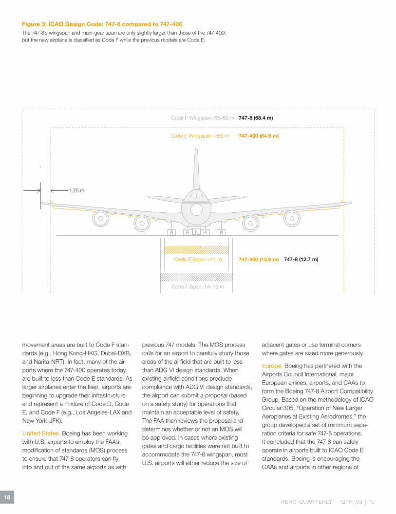
Figure 3: ICAO Design Code: 747-8 compared to 747-400The 747-8’s wingspan and main-gear span are only slightly larger than those of the 747-400, but the new airplane is classified as Code F while the previous models are Code E.
1.75 m
Code E Wingspan: <65 m 747-400 (64.9 m)
747-8 (68.4 m)
747-400 (12.6 m) 747-8 (12.7 m)
Code F Wingspan: 65–80 m
Code E Span: < 14 m
Code F Span: 14–16 m
movement areas are built to Code F stan-dards (e.g., Hong Kong-HKG, Dubai-DXB, and Narita-NRT). In fact, many of the air-ports where the 747-400 operates today are built to less than Code E standards. As larger airplanes enter the fleet, airports are beginning to upgrade their infrastructure and represent a mixture of Code D, Code E, and Code F (e.g., Los Angeles-LAX and New York-JFK).
United States. Boeing has been working with U.S. airports to employ the FAA’s modification of standards (MOS) process to ensure that 747-8 operators can fly into and out of the same airports as with
previous 747!models. The MOS process calls for an airport to carefully study those areas of the airfield that are built to less than ADG VI design standards. When existing airfield conditions preclude compliance with ADG VI design standards, the airport can submit a proposal (based on a safety study) for operations that maintain an acceptable level of safety. The FAA then reviews the proposal and determines whether or not an MOS will be approved. In cases where existing gates and cargo facilities were not built to accommodate the 747-8 wingspan, most U.S. airports will either reduce the size of
adjacent gates or use terminal corners where gates are sized more generously.
Europe. Boeing has partnered with the Airports Council International, major European airlines, airports, and CAAs to form the Boeing 747-8 Airport Compatibility Group. Based on the methodology of ICAO Circular 305, “Operation of New Larger Aeroplanes at Existing Aerodromes,” the group developed a set of minimum sepa-ration criteria for safe 747-8 operations. It concluded that the 747-8 can safely operate in airports built to ICAO Code E standards. Boeing is encouraging the CAAs and airports in other regions of
19WWW.BOEING.COM/COMMERCIAL/AEROMAGAZINE
Figure 4: ICAO Code F compared to Code EFull compliance with ICAO airport requirements would mean relocating taxiways and other airfield elements.
Note: Drawing not to scale.
the world to use the Boeing Airport Compatibility Group’s minimum separation criteria to help them perform their own aeronautical safety study of 747-8 opera-tions. These results can help facilitate approval for the 747-8 to operate at their airport. As with the U.S. airports, to accommodate the 747-8’s wider wingspan at gates, most major airports will either reduce the size of adjacent gates or use terminal corners where gates are sized more generously.
Rest of the world. Some other countries, such as the United Kingdom and Canada, have their own process to accommodate the 747-8 at their 747-400 airports. In countries without a process, Boeing is working with the CAAs to ensure that an aeronautical safety study is conducted according to ICAO Circular 305. The results of the study can be used to determine how 747-8 operations can be safely conducted in their less than Code F airports. If needed, an operational plan can then be used to help facilitate approval for the 747-8 to operate at each airport.
SUMMARY
The 747-8 offers operators increased capacity while taking advantage of existing airport infrastructure. Because its wing-span puts it into the ICAO Code F group, performance of an aeronautical study and, in some cases, application of operational procedures will allow the airplane to operate at existing 747-400 airports.
For more information about airport compatibility, please contact Karen Dix-Colony at karen.s.dix-colony@ boeing.com.
Airfield Characteristics
ICAO Code E / F
Meters Feet
Runway Width 45 / 60 148 / 197
Runway + Shoulder!Width
60 / 75 197 / 246
Taxiway Width 23 / 25 75 / 82
Taxiway + Shoulder!Width
44 / 60 144 / 197
Runway – Taxiway Separation
182.5 / 190 599 / 623
Taxiway – Taxiway Separation
80 / 97.5 262 / 320
Taxiway – Object Separation
47.5 / 57.5 156 / 189
Taxilane – Object Separation
42.5 / 50.5 139 / 166
Runway Width
Taxiway Width
Taxiway / Object
Runway / Taxiway Separation
Separation
Airlines can now create a customized, prioritized list of improvements in minutes online.
21WWW.BOEING.COM/COMMERCIAL/AEROMAGAZINE
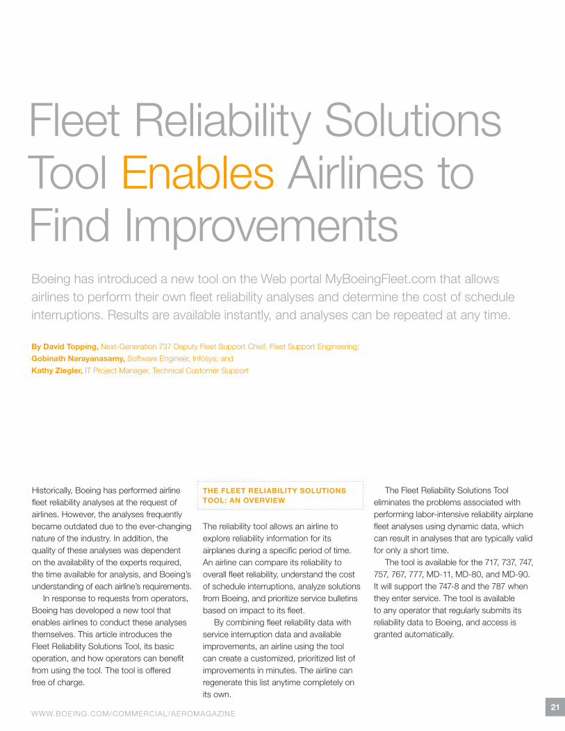
Fleet Reliability Solutions Tool Enables Airlines to Find Improvements
Historically, Boeing has performed airline fleet reliability analyses at the request of airlines. However, the analyses frequently became outdated due to the ever-changing nature of the industry. In addition, the quality of these analyses was dependent on the availability of the experts required, the time available for analysis, and Boeing’s understanding of each airline’s requirements.
In response to requests from operators, Boeing has developed a new tool that enables airlines to conduct these analyses themselves. This article introduces the Fleet Reliability Solutions Tool, its basic operation, and how operators can benefit from using the tool. The tool is offered free of charge.
THE FLEET RELIABILITY SOLUTIONS TOOL: AN OVERVIEW
The reliability tool allows an airline to explore reliability information for its airplanes during a specific period of time. An airline can compare its reliability to overall fleet reliability, understand the cost of schedule interrup tions, analyze solutions from Boeing, and prioritize service bulletins based on impact to its fleet.
By combining fleet reliability data with service interruption data and available improvements, an airline using the tool can create a customized, prioritized list of improvements in minutes. The airline can regenerate this list anytime completely on its own.
The Fleet Reliability Solutions Tool eliminates the problems associated with performing labor-intensive reliability airplane fleet analyses using dynamic data, which can result in analyses that are typically valid for only a short time.
The tool is available for the 717, 737, 747, 757, 767, 777, MD-11, MD-80, and MD-90. It will support the 747-8 and the 787!when they enter service. The tool is available to any operator that regularly submits its reliability data to Boeing, and access is granted automatically.
Boeing has introduced a new tool on the Web portal MyBoeingFleet.com that allows airlines to perform their own fleet reliability analyses and determine the cost of schedule interruptions. Results are available instantly, and analyses can be repeated at any time.
By David Topping, Next-Generation 737!Deputy Fleet Support Chief, Fleet Support Engineering;Gobinath Narayanasamy, Software Engineer, Infosys; andKathy Ziegler, IT Project Manager, Technical Customer Support
22AERO QUARTERLY QTR_03 | 10
HOW THE FLEET RELIABILITY SOLUTIONS TOOL WORKS
The reliability tool integrates data extracted from existing sources to display the service documents Boeing has available to address the airline’s reliability concerns. Data sources include:
! Airplane data from Boeing’s internal database, including owner, operator, and registration information.
! Fleet Team Xchange recommendations compiled by Boeing.
! Boeing service bulletin completion records supplied by operators.
! Airline reliability data from the Boeing airplane reliability and maintainability database. (Airlines need to submit their reliability data to Boeing in order to be able to use the reliability tool. They can submit data as members of the In-Service Data Program or
through their Boeing Field Service representatives.)
! Economic analysis data, including schedule interruption costs as cal-culated by Boeing or the airline.
! Effective Boeing service bulletins, service letters, maintenance tips, and Fleet Team Digest articles.
The Fleet Reliability Solutions Tool automatically links data from these sources, allowing each reliability issue to be asso-ciated with the available Boeing service solutions. It also presents a summary of reliability issues by airplane for the period being analyzed. Users can add airplanes to or remove them from the analysis to further refine the solutions based on a subsection of the fleet, down to an indi-vidual airplane. This allows operators to quickly understand where to invest their fleet improvement budgets.
Integrated reliability information and available Boeing solutions are displayed in several different report formats that can easily be customized or sorted by a number of parameters, including occur-rence, cost, type of schedule interruption, and type of Boeing solution.
USING THE FLEET RELIABILITY SOLUTIONS TOOL
The reliability tool can be accessed by clicking on the Fleet Reliability Solutions Tool link on the MyBoeingFleet.com home page. Each reliability analysis begins by specifying the parameters of the analysis. Parameters include airplane model, analysis time period, and cost factors. The operator has the option of comparing the individual airline’s reliability statistics with the overall fleet (see fig.!1, step!1). (Note: Each indivi-dual operator’s data, including logbook
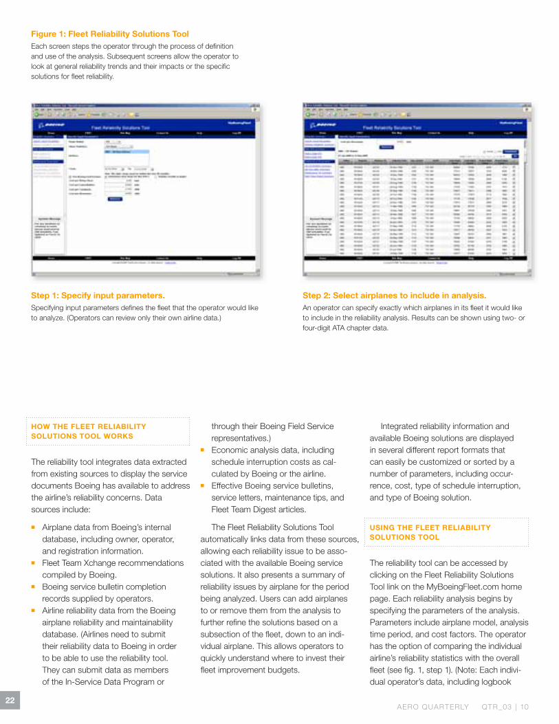
Figure 1: Fleet Reliability Solutions ToolEach screen steps the operator through the process of definition and use of the analysis. Subsequent screens allow the operator to look at general reliability trends and their impacts or the specific solutions for fleet reliability.
Step 2: Select airplanes to include in analysis.An operator can specify exactly which airplanes in its fleet it would like to include in the reliability analysis. Results can be shown using two- or four-digit ATA chapter data.
Step 1: Specify input parameters.Specifying input parameters defines the fleet that the operator would like to analyze. (Operators can review only their own airline data.)
23WWW.BOEING.COM/COMMERCIAL/AEROMAGAZINE
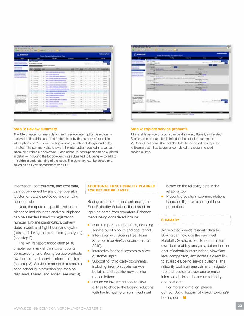
information, configuration, and cost data, cannot be viewed by any other operator. Customer data is protected and remains confidential.)
Next, the operator specifies which air-planes to include in the analysis. Airplanes can be selected based on registration number, airplane identification, delivery date, model, and flight hours and cycles (total and during the period being analyzed) (see step 2).
The Air Transport Association (ATA) chapter summary shows costs, counts, comparisons, and Boeing service products available for each service interruption item (see step 3). Service products that address each schedule interruption can then be displayed, filtered, and sorted (see step 4).
ADDITIONAL FUNCTIONALITY PLANNED FOR FUTURE RELEASES
Boeing plans to continue enhancing the Fleet Reliability Solutions Tool based on input gathered from operators. Enhance-ments being considered include:
! Built-in reporting capabilities, including service bulletin hours and cost report.
! Integration with Boeing Fleet Team Xchange (see AERO second-quarter 2010).
! Interactive feedback system to allow customer input.
! Support for third-party documents, including links to supplier service bulletins and supplier service infor-mation letters.
! Return on investment tool to allow airlines to choose the Boeing solutions with the highest return on investment
based on the reliability data in the reliability tool.
! Preventive solution recommendations based on flight-cycle or flight-hour projections.
SUMMARY
Airlines that provide reliability data to Boeing can now use the new Fleet Reliability Solutions Tool to perform their own fleet reliability analyses, determine the cost of schedule interruptions, view fleet level comparison, and access a direct link to available Boeing service bulletins. The reliability tool is an analysis and navigation tool that customers can use to make informed decisions based on reliability and cost data.
For more information, please contact David Topping at [email protected].
Step 3: Review summary.The ATA chapter summary details each service interruption based on its rank within the airline and fleet (determined by the number of schedule interruptions per 100!revenue flights), cost, number of delays, and delay minutes. The summary also shows if the interruption resulted in a cancel-lation, air turnback, or diversion. Each schedule interruption can be explored in detail — including the logbook entry as submitted to Boeing — to add to the airline’s understanding of the issue. The summary can be sorted and saved as an Excel spreadsheet or a PDF.
Step 4: Explore service products.All available service products can be displayed, filtered, and sorted. Each service product title is linked to the actual document on MyBoeingFleet.com. The tool also tells the airline if it has reported to Boeing that it has begun or completed the recommended service bulletin.
3
24AERO QUARTERLY QTR_03 | 10
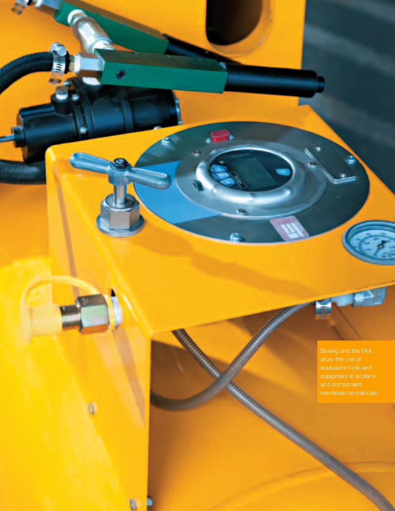
Boeing and the FAA allow the use of equivalent tools and equipment in airplane and component maintenance manuals.
25WWW.BOEING.COM/COMMERCIAL/AEROMAGAZINE
Understanding Tools and Equipment Equivalency
Being able to quickly determine the equiv-alency of commercial tools and equipment can reduce or eliminate related airplane maintenance delays for operators.
This article explains how to determine the equivalency of commercial tools, as well as the equivalency of special tools and equipment. It also addresses general equivalency issues about tools, equipment, and ground-support equipment.
While most of the equivalency questions received by Boeing deal with commercial tools and equipment in Boeing AMMs, the same questions and resolutions can be applied to commercial tools and equipment in component maintenance manuals (CMMs), Boeing fault isolation
manuals, and the Boeing standard wiring practices manual.
Standard tools are those not normally found in a mechanic’s toolbox but are required to perform airplane maintenance. These items, such as oil resistant buckets and torque wrenches, do not have vendor part numbers. Because there are not many equivalency questions about these tools, they are not discussed in this article.
BASIS FOR EQUIVALENCY
The use of equivalent tools and equipment has been established by Boeing, original
equipment manufacturers (OEMs), and the U.S. Federal Aviation Administration (FAA):
! Boeing allows the use of equivalent tools and equipment throughout AMM procedures, including the introduction to AMM Part II (Practices and Procedures) and the Tools/Equipment sections.
! OEMs such as airplane component sup-pliers allow the use of equivalent tools and equipment in the Testing and Fault Isolation and Special Tools, Fixtures, and Equipment sections of their CMM.
! The FAA allows the use of equivalent tools and equipment as stated in Title 14!Code of Federal Regulations Part 145.109!(c) and in Federal Aviation Regulation 43.13(a).
Operators often contact Boeing asking whether commercial tools and equipment from different vendors or with different part numbers are equivalent to those listed in Boeing airplane maintenance manuals (AMMs). In general, if the specifications of the tool or equipment meet or exceed the specifications of the AMM procedures, they are considered to be equivalent to the commercial tool or equipment recommended in the AMM.
By Giday Girmay, Associate Technical Fellow, Maintenance and Ground Operations Systems
26AERO QUARTERLY QTR_03 | 10
ESTABLISHING EQUIVALENCY FOR COMMERCIAL TOOLS AND EQUIPMENT
Most commercial tools and equipment used in AMMs and CMMs are generic in nature and are designed to make measure-ments that are not unique to any specific test procedure in AMMs or CMMs. They are used across different test procedures as applicable and are referred to as commercial-off-the-shelf tools and equip-ment. They are available from multiple vendors with different part numbers and physical attributes and perform the same or different functions. They may include industry standard tools and equipment such as wrenches, multimeters, and sockets that are manufactured to a recognized industry standard.
To determine equivalency of commercial tools and equipment, users should first ensure that the tool or equipment falls under the definition of commercial tools and equipment as discussed above. (All commercial tools and equipment in the AMMs are identified by Boeing internal reference numbers beginning with the prefix “COM,” which stands for commercial. These reference numbers are listed in a table in the introduction section of the AMMs and throughout the tools and equip ment sections of the AMM procedures.) Commercial tools and equipment listed in AMMs include:
! Multimeters, ammeters, megohmmeters, bonding meters, and Inductance Capaci-tance Resistance (i.e., LCR) meters.
! Decade resistance boxes, gauges, borescopes, and frequency counters.
! Aeronautical Radio Incorporated (ARINC) 429/629!data loaders and ARINC 429/629!data bus analyzers.
! Tools (including crimping and swaging tools).
! Jacks (including tripod, axle, and hydraulic).
The key criterion for equivalency between commercial tools and equipment is their function: an equivalent commercial tool or equipment must perform the same function and deliver the same result in a given AMM task procedure as the recom-mended commercial tool or equipment. To establish equivalency for commercial tools and equipment, locate and identify the
airplane test or measurement specifications in the AMM procedures and compare them to the specifications of the proposed equiv-alent tool or equipment. If the specifications of the tool or equipment meet or exceed the specifications of all applicable AMM procedures, they are considered to be equivalent to the commercial tool or equip-ment recommended in the AMM procedure.
Do not use direct comparisons of com-mercial tools and equipment specifications as a method for determining equivalency. Although commercial tools and equipment with identical specifications would be con-sidered equivalent, they are not required to have identical specifications to be equivalent. For example, it is often possible for two different digital multimeters made by different vendors and having different specifications to satisfy the measurement or test requirements of a given AMM procedure. In this case, both multimeters meet the equivalency criterion for the specific AMM procedure without being identical in their specifications, looks, and dimensions. The equivalent commercial tool or equipment specifications must only satisfy the measurement or test require-ments in the AMM procedures. This is how functional equivalency is established between the commercial tools and equip-ment in question and those recommended in the AMM procedures.
In addition, commercial tools and equipment are not required to have the same form (e.g., shape, appearance, weight, and dimensions) to be equivalent, nor must they be designed to specifically fit or interface with an airplane or its compo-nents. They can use adapters to interface with various products.
Some commercial tools and equipment, such as bonding meters, must be approved explosion proof and intrinsically safe to be operated around fueled airplanes. This special requirement is specified along with the equipment part numbers in the AMM equipment list section. Such special requirements are also highlighted in the vendor catalog of the commercial tools and equipment. To establish equivalency, any such additional special requirements must be consistently applied to the poten-tially equivalent tools and equipment, in addition to comparing the tools and
equipment specification with the AMM procedure specifications.
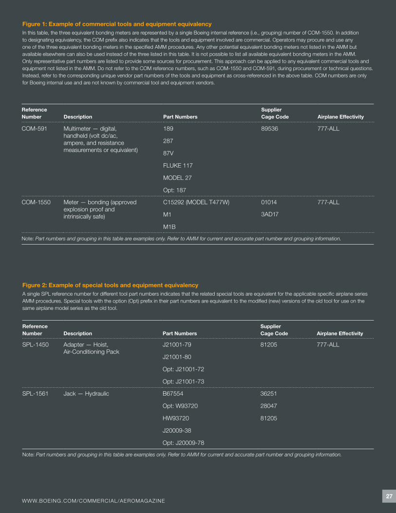
Equivalent commercial tools and equipment in the AMM are identified and designated with a single generic grouping reference number, beginning with the prefix “COM” followed by sequence numbers, such as COM-591 (see fig.!1).
ESTABLISHING EQUIVALENCY FOR SPECIAL TOOLS AND EQUIPMENT
Special tools and equipment are designed solely to support specific airplane com-ponent or system maintenance task procedure(s) as specified in AMMs and CMMs. They have little or no commercial use except to support the specific product maintenance for which they are designed. Normally, there is no equivalent commercial tool or equipment available to perform the related specific maintenance functions. They are primarily designed by the OEM of the airplane or component on which they are used, not by third-party vendors. Examples include all Boeing-designed special tools and equipment used in Boeing AMMs and CMMs.
Equivalency for special tools and equip-ment is established by comparing the specifications of the recommended and equivalent tools or equipment. This goes beyond the functional equivalency criterion used for commercial tools and equipment. Potentially equivalent special tools and equip ment must be proved to be equivalent in form and fit (i.e., interface) as well as func-tion to those recommended in the applicable AMM procedures. This may include equiv-alency in accuracies, tolerances, safety (i.e., proof load), physical interface or appearance, and functional specifications.
In order to use equivalent special tools and equipment in place of those recom-mended in the AMM, equivalency must be established by following the detailed guidance provided in the ARINC Report 668, “Guidance for Tool and Test Equip-ment (TTE) Equivalency.” This report is available from Aeronautical Radio, Inc., 2551!Riva Road Annapolis, MD 21401. This extremely detailed and extensive process is beyond the scope of this article. However, the importance of using the guide for this purpose cannot be overstated.
27WWW.BOEING.COM/COMMERCIAL/AEROMAGAZINE
Figure 1: Example of commercial tools and equipment equivalencyIn this table, the three equivalent bonding meters are represented by a single Boeing internal reference (i.e., grouping) number of COM-1550. In addition to designating equivalency, the COM prefix also indicates that the tools and equipment involved are commercial. Operators may procure and use any one of the three equivalent bonding meters in the specified AMM procedures. Any other potential equivalent bonding meters not listed in the AMM but available elsewhere can also be used instead of the three listed in this table. It is not possible to list all available equivalent bonding meters in the AMM. Only representative part numbers are listed to provide some sources for procurement. This approach can be applied to any equivalent commercial tools and equipment not listed in the AMM. Do not refer to the COM reference numbers, such as COM-1550!and COM-591, during procurement or technical questions. Instead, refer to the corresponding unique vendor part numbers of the tools and equipment as cross-referenced in the above table. COM numbers are only for Boeing internal use and are not known by commercial tool and equipment vendors.
Reference Number Description Part Numbers
Supplier Cage!Code Airplane Effectivity
COM-591 Multimeter — digital, handheld (volt dc/ac, ampere, and resistance measurements or equivalent)
189
287
87V
FLUKE 117
MODEL 27
Opt: 187
89536 777-ALL
COM-1550 Meter — bonding (approved explosion proof and intrinsically safe)
C15292!(MODEL T477W)
M1
M1B
01014 777-ALL
3AD17
Note: Part numbers and grouping in this table are examples only. Refer to AMM for current and accurate part number and grouping information.
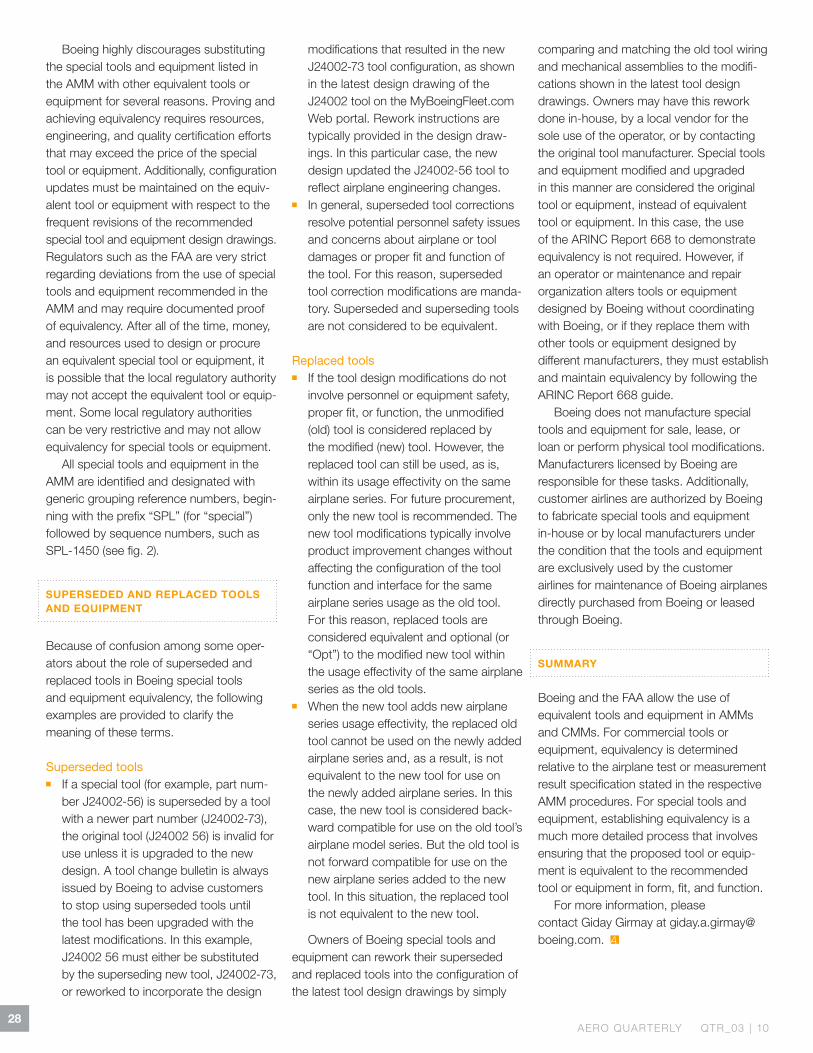
Figure 2: Example of special tools and equipment equivalencyA single SPL reference number for different tool part numbers indicates that the related special tools are equivalent for the applicable specific airplane series AMM procedures. Special tools with the option (Opt) prefix in their part numbers are equivalent to the modified (new) versions of the old tool for use on the same airplane model series as the old tool.
Reference Number Description Part Numbers
Supplier Cage Code Airplane Effectivity
SPL-1450 Adapter — Hoist, Air-Conditioning Pack
J21001-79
J21001-80
Opt: J21001-72
Opt: J21001-73
81205 777-ALL
SPL-1561 Jack — Hydraulic B67554
Opt: W93720
HW93720
J20009-38
Opt: J20009-78
36251
28047
81205
Note: Part numbers and grouping in this table are examples only. Refer to AMM for current and accurate part number and grouping information.
28AERO QUARTERLY QTR_03 | 10
Boeing highly discourages substituting the special tools and equipment listed in the AMM with other equivalent tools or equipment for several reasons. Proving and achieving equivalency requires resources, engineering, and quality certification efforts that may exceed the price of the special tool or equipment. Additionally, configuration updates must be maintained on the equiv-alent tool or equipment with respect to the frequent revisions of the recommended special tool and equipment design drawings. Regulators such as the FAA are very strict regarding deviations from the use of special tools and equipment recommended in the AMM and may require documented proof of equivalency. After all of the time, money, and resources used to design or procure an equivalent special tool or equipment, it is possible that the local regulatory authority may not accept the equivalent tool or equip-ment. Some local regulatory author ities can be very restrictive and may not allow equivalency for special tools or equipment.
All special tools and equipment in the AMM are identified and designated with generic grouping reference numbers, begin-ning with the prefix “SPL” (for “special”) followed by sequence numbers, such as SPL-1450!(see fig.!2).
SUPERSEDED AND REPLACED TOOLS AND EQUIPMENT
Because of confusion among some oper-ators about the role of superseded and replaced tools in Boeing special tools and equipment equivalency, the following examples are provided to clarify the meaning of these terms.
Superseded tools ! If a special tool (for example, part num-
ber J24002-56) is superseded by a tool with a newer part number (J24002-73), the original tool (J24002!56) is invalid for use unless it is upgraded to the new design. A tool change bulletin is always issued by Boeing to advise customers to stop using superseded tools until the tool has been upgraded with the latest modifications. In this example, J24002!56!must either be sub stituted by the superseding new tool, J24002-73, or reworked to incorporate the design
modifications that resulted in the new J24002-73!tool configuration, as shown in the latest design drawing of the J24002 tool on the MyBoeingFleet.com Web portal. Rework instructions are typically provided in the design draw-ings. In this particular case, the new design updated the J24002-56 tool to reflect airplane engineering changes.
! In general, superseded tool corrections resolve potential personnel safety issues and concerns about airplane or tool damages or proper fit and function of the tool. For this reason, superseded tool correction modifications are manda-tory. Superseded and superseding tools are not considered to be equivalent.
Replaced tools ! If the tool design modifications do not
involve personnel or equipment safety, proper fit, or function, the unmodified (old) tool is considered replaced by the modified (new) tool. However, the replaced tool can still be used, as is, within its usage effectivity on the same airplane series. For future procurement, only the new tool is recommended. The new tool modifications typically involve product improvement changes without affecting the configuration of the tool function and interface for the same airplane series usage as the old tool. For this reason, replaced tools are consid ered equivalent and optional (or “Opt”) to the modified new tool within the usage effectivity of the same airplane series as the old tools.
! When the new tool adds new airplane series usage effectivity, the replaced old tool cannot be used on the newly added airplane series and, as a result, is not equivalent to the new tool for use on the newly added airplane series. In this case, the new tool is considered back-ward compatible for use on the old tool’s airplane model series. But the old tool is not forward compatible for use on the new airplane series added to the new tool. In this situation, the replaced tool is not equivalent to the new tool.
Owners of Boeing special tools and equipment can rework their superseded and replaced tools into the configuration of the latest tool design drawings by simply
comparing and matching the old tool wiring and mechanical assemblies to the modifi-ca tions shown in the latest tool design drawings. Owners may have this rework done in-house, by a local vendor for the sole use of the operator, or by contacting the original tool manufacturer. Special tools and equipment modified and upgraded in this manner are considered the original tool or equipment, instead of equivalent tool or equipment. In this case, the use of the ARINC Report 668!to demonstrate equiv alency is not required. However, if an operator or maintenance and repair organization alters tools or equipment designed by Boeing without coordinating with Boeing, or if they replace them with other tools or equipment designed by different manufacturers, they must establish and maintain equivalency by following the ARINC Report 668!guide.
Boeing does not manufacture special tools and equipment for sale, lease, or loan or perform physical tool modifications. Manufacturers licensed by Boeing are responsible for these tasks. Additionally, customer airlines are authorized by Boeing to fabricate special tools and equipment in-house or by local manufacturers under the condition that the tools and equipment are exclusively used by the customer airlines for maintenance of Boeing airplanes directly purchased from Boeing or leased through Boeing.
SUMMARY
Boeing and the FAA allow the use of equivalent tools and equipment in AMMs and CMMs. For commercial tools or equipment, equivalency is determined relative to the airplane test or measurement result specification stated in the respective AMM procedures. For special tools and equipment, establishing equivalency is a much more detailed process that involves ensuring that the proposed tool or equip-ment is equivalent to the recommended tool or equipment in form, fit, and function.
For more information, please contact Giday Girmay at [email protected].


www.boeing.com/commercial/aeromagazine

![Ruff Newsletter Oct2010[1]](https://static.fdocuments.in/doc/165x107/577d35991a28ab3a6b90e32e/ruff-newsletter-oct20101.jpg)