Aero Electric Connector Catalog
135
Aero - Electric Connector A CONESYS COMPANY Military Specified Circular Connectors MILITARY AEROSPACE TRANSPORTATION GEOPHYSICAL INDUSTRIAL
Transcript of Aero Electric Connector Catalog

Aero-Electric ConnectorA CONESYS COMPANY
Military Specified Circular Connectors
MILITARY AEROSPACE TRANSPORTATION GEOPHYSICAL INDUSTRIAL

1– –www.conesys.com [email protected]
Aero-Electric Connector, Inc.Table of Contents
Mil Spec Catalog (AE101)
MIL-DTL-38999 Series I . . . . . . . . . . . . . . . . . . . . . . . . . . . . . . . . . . . . . . . . . . . . . . . . . . . . . . . . . . . . . . . . . . . . . . . . . . . . . . . . . . . . . . . . . 2–19MS27466 (AE166) Front Wall Mount Receptacle . . . . . . . . . . . . . . . . . . . . . . . . . . . . . . . . . . . . . . . . . . . . . . . . . . . . . . . . . . . . . . . . 5MS27656 (AE156) Rear Wall Mount Receptacle . . . . . . . . . . . . . . . . . . . . . . . . . . . . . . . . . . . . . . . . . . . . . . . . . . . . . . . . . . . . . . . . 6MS27496 (AE196) Front Box Mount Receptacle . . . . . . . . . . . . . . . . . . . . . . . . . . . . . . . . . . . . . . . . . . . . . . . . . . . . . . . . . . . . . . . . 7 MS27505 (AE105) Rear Box Mount Receptacle . . . . . . . . . . . . . . . . . . . . . . . . . . . . . . . . . . . . . . . . . . . . . . . . . . . . . . . . . . . . . . . . 8MS27468 (AE168) Jam Nut Receptacle . . . . . . . . . . . . . . . . . . . . . . . . . . . . . . . . . . . . . . . . . . . . . . . . . . . . . . . . . . . . . . . . 9MS27467 (AE167) RFI Grounding Plug . . . . . . . . . . . . . . . . . . . . . . . . . . . . . . . . . . . . . . . . . . . . . . . . . . . . . . . . . . . . . . . . 10
MIL-DTL-38999 Series II. . . . . . . . . . . . . . . . . . . . . . . . . . . . . . . . . . . . . . . . . . . . . . . . . . . . . . . . . . . . . . . . . . . . . . . . . . . . . . . . . . . . . . . . .20–35MS27472 (AE272) Front Wall Mount Receptacle . . . . . . . . . . . . . . . . . . . . . . . . . . . . . . . . . . . . . . . . . . . . . . . . . . . . . . . . . . . . . . . .23MS27497 (AE297) Rear Wall Mount Receptacle . . . . . . . . . . . . . . . . . . . . . . . . . . . . . . . . . . . . . . . . . . . . . . . . . . . . . . . . . . . . . . . .24MS27499 (AE299) Front Box Mount Receptacle . . . . . . . . . . . . . . . . . . . . . . . . . . . . . . . . . . . . . . . . . . . . . . . . . . . . . . . . . . . . . . . .25MS27508 (AE208) Rear Box Mount Receptacle . . . . . . . . . . . . . . . . . . . . . . . . . . . . . . . . . . . . . . . . . . . . . . . . . . . . . . . . . . . . . . . .26MS27513 (AE213) Front Box Mount Receptacle, Long Grommet . . . . . . . . . . . . . . . . . . . . . . . . . . . . . . . . . . . . . . . . . . . . . . . . . .27MS27474 (AE274) Jam Nut Receptacle . . . . . . . . . . . . . . . . . . . . . . . . . . . . . . . . . . . . . . . . . . . . . . . . . . . . . . . . . . . . . . . .28MS27473 (AE273) Straight Plug . . . . . . . . . . . . . . . . . . . . . . . . . . . . . . . . . . . . . . . . . . . . . . . . . . . . . . . . . . . . . . . .29MS27484 (AE284) RFI Grounding Plug . . . . . . . . . . . . . . . . . . . . . . . . . . . . . . . . . . . . . . . . . . . . . . . . . . . . . . . . . . . . . . . .30MS27500 (AE200) Plug with 90º Clamp . . . . . . . . . . . . . . . . . . . . . . . . . . . . . . . . . . . . . . . . . . . . . . . . . . . . . . . . . . . . . . . .31
MIL-DTL-38999 Series III . . . . . . . . . . . . . . . . . . . . . . . . . . . . . . . . . . . . . . . . . . . . . . . . . . . . . . . . . . . . . . . . . . . . . . . . . . . . . . . . . . . . . . . 36–45D38999/20 (AE320) Wall Mount Receptacle . . . . . . . . . . . . . . . . . . . . . . . . . . . . . . . . . . . . . . . . . . . . . . . . . . . . . . . . . . . . . . . .39D38999/24 (AE324) Jam Nut Receptacle . . . . . . . . . . . . . . . . . . . . . . . . . . . . . . . . . . . . . . . . . . . . . . . . . . . . . . . . . . . . . . . 40D38999/26 (AE326) Self-Locking, RFI Grounding Plug . . . . . . . . . . . . . . . . . . . . . . . . . . . . . . . . . . . . . . . . . . . . . . . . . . . . . . . . . 41
MIL-DTL-5015 (Series III) Rear Release . . . . . . . . . . . . . . . . . . . . . . . . . . . . . . . . . . . . . . . . . . . . . . . . . . . . . . . . . . . . . . . . . . . . . . . . 46–68MS3450 (AE550) Wall Mount Receptacle . . . . . . . . . . . . . . . . . . . . . . . . . . . . . . . . . . . . . . . . . . . . . . . . . . . . . . . . . 49MS3451 (AE551) Cable Connecting Receptacle . . . . . . . . . . . . . . . . . . . . . . . . . . . . . . . . . . . . . . . . . . . . . . . . . . . . . . . . . 50MS3452 (AE552) Box Mount Receptacle . . . . . . . . . . . . . . . . . . . . . . . . . . . . . . . . . . . . . . . . . . . . . . . . . . . . . . . . . 51MS3454 (AE554) Jam Nut Receptacle . . . . . . . . . . . . . . . . . . . . . . . . . . . . . . . . . . . . . . . . . . . . . . . . . . . . . . . . . 52MS3456 (AE556) Straight Plug . . . . . . . . . . . . . . . . . . . . . . . . . . . . . . . . . . . . . . . . . . . . . . . . . . . . . . . . . 53MS3459 (AE559) Self-Locking Plug . . . . . . . . . . . . . . . . . . . . . . . . . . . . . . . . . . . . . . . . . . . . . . . . . . . . . . . . . 54
MIL-DTL-26482 Series 2 . . . . . . . . . . . . . . . . . . . . . . . . . . . . . . . . . . . . . . . . . . . . . . . . . . . . . . . . . . . . . . . . . . . . . . . . 69–85MS3470 (AE770) Narrow Flange Receptacle . . . . . . . . . . . . . . . . . . . . . . . . . . . . . . . . . . . . . . . . . . . . . . . . . . . . . . . . . 72MS3471 (AE771) Cable Connecting Receptacle . . . . . . . . . . . . . . . . . . . . . . . . . . . . . . . . . . . . . . . . . . . . . . . . . . . . . . . . . 73MS3472 (AE772) Wide Flange Receptacle . . . . . . . . . . . . . . . . . . . . . . . . . . . . . . . . . . . . . . . . . . . . . . . . . . . . . . . . . 74MS3474 (AE774) Jam Nut Receptacle . . . . . . . . . . . . . . . . . . . . . . . . . . . . . . . . . . . . . . . . . . . . . . . . . . . . . . . . . 75MS3476 (AE776) Straight Plug . . . . . . . . . . . . . . . . . . . . . . . . . . . . . . . . . . . . . . . . . . . . . . . . . . . . . . . . . 76MS3475 (AE775) RFI Grounding Plug . . . . . . . . . . . . . . . . . . . . . . . . . . . . . . . . . . . . . . . . . . . . . . . . . . . . . . . . . 77AC3475 Arctic Coupling Nut, RFI Plug . . . . . . . . . . . . . . . . . . . . . . . . . . . . . . . . . . . . . . . . . . . . . . . . . . . . . . . . . 78
MIL-DTL-83723 Series III . . . . . . . . . . . . . . . . . . . . . . . . . . . . . . . . . . . . . . . . . . . . . . . . . . . . . . . . . . . . . . . . . . . . . . . . 86–108M83723/71, 72 (AE83371, 72) Wall Mount Receptacle, Bayonet . . . . . . . . . . . . . . . . . . . . . . . . . . . . . . . . . . . . . . . . . . . . . . 89M83723/73, 74 (AE83373, 74) Jam Nut Receptacle, Bayonet . . . . . . . . . . . . . . . . . . . . . . . . . . . . . . . . . . . . . . . . . . . . . . . . . . . 90M83723/75, 76 (AE83375, 76) Straight Plug, Bayonet . . . . . . . . . . . . . . . . . . . . . . . . . . . . . . . . . . . . . . . . . . . . . . . . . . . . 91M83723/77, 78 (AE83377, 78) RFI Grounding Plug, Bayonet . . . . . . . . . . . . . . . . . . . . . . . . . . . . . . . . . . . . . . . . . . . . . . . . . . . . 92M83723/82, 83 (AE83382, 83) Wall Mount Receptacle, Threaded . . . . . . . . . . . . . . . . . . . . . . . . . . . . . . . . . . . . . . . . . . . . . . . . 94M83723/84, 85 (AE83384, 85) Jam Nut Receptacle, Threaded . . . . . . . . . . . . . . . . . . . . . . . . . . . . . . . . . . . . . . . . . . . . . . . . . . . . 95M83723/86, 87 (AE83386, 87) Straight Plug, Threaded . . . . . . . . . . . . . . . . . . . . . . . . . . . . . . . . . . . . . . . . . . . . . . . . . . . . 96M83723/91, 92 (AE83391, 92) RFI Grounding Plug, Threaded . . . . . . . . . . . . . . . . . . . . . . . . . . . . . . . . . . . . . . . . . . . . . . . . . . . . 97M83723/95, 96 (AE83395, 96) Self-Locking Plug, Threaded . . . . . . . . . . . . . . . . . . . . . . . . . . . . . . . . . . . . . . . . . . . . . . . . . . . . 98M83723/97, 98 (AE83397, 98) Self-Locking RFI Plug, Threaded . . . . . . . . . . . . . . . . . . . . . . . . . . . . . . . . . . . . . . . . . . . . . . 99M83723/68, 69 (AE83368, 69) Lanyard Release Plug . . . . . . . . . . . . . . . . . . . . . . . . . . . . . . . . . . . . . . . . . . . . . . . . . . . . 100M83723/70 (AE83370) Receptacle Adapter for Lanyard Release Plug . . . . . . . . . . . . . . . . . . . . . . . . . . . . . . . . . . . . . 101
MIL-DTL-26500 . . . . . . . . . . . . . . . . . . . . . . . . . . . . . . . . . . . . . . . . . . . . . . . . . . . . . . . . . . . . . . . . . . . . . . . . 109–123MS24264R**B (AE664R**B) Wall Mount Receptacle, Bayonet . . . . . . . . . . . . . . . . . . . . . . . . . . . . . . . . . . . . . . . . . . . . . . 112MS24265R**B (AE665R**B) Jam Nut Receptacle, Bayonet . . . . . . . . . . . . . . . . . . . . . . . . . . . . . . . . . . . . . . . . . . . . . . 113MS24266R**B (AE666R**B) Straight Plug, Bayonet . . . . . . . . . . . . . . . . . . . . . . . . . . . . . . . . . . . . . . . . . . . . . . 114MS24264R**T (AE664R**T) Wall Mount Receptacle, Threaded . . . . . . . . . . . . . . . . . . . . . . . . . . . . . . . . . . . . . . . . . . . . . . 115MS24265R**T (AE665R**T) Jam Nut Receptacle, Threaded . . . . . . . . . . . . . . . . . . . . . . . . . . . . . . . . . . . . . . . . . . . . . . 116MS24266R**T (AE666R**T) Straight Plug, Threaded . . . . . . . . . . . . . . . . . . . . . . . . . . . . . . . . . . . . . . . . . . . . . . 117
Cross Reference . . . . . . . . . . . . . . . . . . . . . . . . . . . . . . . . . . . . . . . . . . . . . . . . . . . . . . . . . . . . . . . . . . . . . . . 124–129Glossary of Terms . . . . . . . . . . . . . . . . . . . . . . . . . . . . . . . . . . . . . . . . . . . . . . . . . . . . . . . . . . . . . . . . . . . . . . . 130–132
38999 S I
38999 S II
38999 S III
5015 S III
26482 S 2
83723 S III
26500

2www.conesys.com [email protected]
MIL–D
TL–
38999 S I
– –
MIL-DTL-38999Features and ApplicationSeries I
www.conesys.com [email protected]
Features and Application
MIL-DTL-38999 Series I is a bayonet coupling subminiature configuration with high contact density, ideal for smallerwire gauge, general-purpose applications. These environment-resisting connectors are 100% “scoop-proof.” Pins arerecessed in elongated shells to prevent the possibility ofbending contacts when plugs are scooped into the matingreceptacles.
This family of connectors is offered in 5 receptacle-mountingstyles. They include square flange receptacles, for both frontand rear panel (wall) mounting; square flange receptacles, forboth front and rear box mounting; and jam nut receptacleswhich incorporate “O” ring seals, designed for rear panel“D” hole mounting.
Standard plugs provide RFI protection by incorporating acontinuous strip of attached grounding fingers attenuatinginterference up to 1 GHz.
Fifty-seven insert arrangements per MIL-STD-1560 aretooled and qualified to MIL-DTL-38999 Series I, utilizing 2 to 128 contacts. Contacts come in sizes 22M, 22D, 20, 16,12, and 8 (coax and twinax), terminating wire sizes from 28gauge to 12 gauge including coaxial cable.
These connectors are available in wide range of shell materialsand finishes. Aluminum shells are offered in electroless nickel,olive drab cadmium and bright cadmium. Other finishessuch as anodic and zinc nickel are available upon request tocommercial callouts only. In addition, we offer passivatedstainless steel shells with standard environment-resistinginserts (commercial callouts only), and for highly corrosiveenvironments, nickel-aluminum-bronze shells with standardenvironment-resisting inserts (commercial callouts only).
Universal I/R Tool – A single, expendable plastic tool is usedfor both insertion and removal of contacts.
Scoop-Proof Design – Recessed pins in elongated shellsminimize the possibility for contact damage. In a blindmating application, mating shells cannot “scoop” the pins,and cause a shorting or bending of contacts.
Closed-Entry Socket Insert – Hard dielectric socket facehas lead-in chamfers for positive alignment of pins (evenpartially bent within pre-established limits) with sockets.
Interfacial Pin Insert Seal – Raised moisture barriersaround each pin, which mate into lead-in chamfers of hardface socket insert, provide individual contact sealing.Interfacial seal is never touched by service tools.
Elastomer Wire Sealing Grommet – Sealing over a widerange of wire diameters is assured by a triple wire seal ineach cavity at the rear of the connector.
Superior Contact Stability – Rear release crimp contactsystem features a stamped beryllium-copper retaining clipcaptivated by molded-in shoulders of each contact cavity inthe insulator. A rear-inserted M81969 plastic tool expandsthe tines beyond the shoulder, releasing the contact.
Shell Polarization – Alternate key/keyway positions preventcross mating of adjacent connectors having identical insertarrangement.

3www.conesys.com [email protected]
MIL–D
TL–
38999 S I
– –
MIL-DTL-38999Performance Specifications
Series I
www.conesys.com [email protected]
Performance SpecificationsOperating Temperature RangeFinish B: -65°C to +175°C (-85°F to +347°F)Finish F: -65°C to +200°C (-85°F to +392°FFinish A: -65°C to +150°C (-85°F to +302°F)
Material and Plating Data (Finish)B – aluminum shell, olive drab cadmium over nickel base F – aluminum shell, electroless nickel finishA– aluminum shell, silver to light iridescent yellow color(bright) cadmium over electroless nickel
Corrosion ResistanceFinishes A and B withstand 500-hour salt spray.Finish F withstands 48-hour salt spray.
DurabilityMinimum of 500 mating cycles
Environmental SealWired, mated connectors with specified accessoriesattached, shall meet the altitude-immersion test specified inMIL-DTL-38999.
Fluid ResistanceConnectors resist specified immersions in MIL-PRF-7808,MIL-PRF-23699, MIL-PRF-5606, M2-V Chevron oil, Coolanol25, MIL-DTL-83133 (JP-8), MIL-DTL-5624 (JP-4, JP-5),SAE-AMS1424 Type I, and other solvents and cleaning agents.
Shell-to-Shell Conductivity� Finish F = 1.0 millivolt maximum potential drop� Finishes A and B = 2.5 millivolts maximum potential drop
Voltage Rating
Shielding EffectivenessRFI and EMI attenuation at the specified frequencies meetthe requirements of MIL-DTL-38999.� RFI shielding effectiveness of mated connectors with RFI
backshells is measured in a triaxial radio frequency leak-age fixture.
� EMI shielding effectiveness is measured at the interfaceof mated connectors and tested by the mode-stirredtechnique specified in method 3008 of MIL-STD-1344.
Shock and Vibration RequirementsWired, mated connectors shall not be damaged, nor shallthere be a current interruption longer than one microsecondwhen subjected to the following:
Standard ShockMated connectors withstand a pulse of approximate halfsine wave of 300 G ± 15 percent magnitude with duration of3 ± 1 milliseconds applied in three axes per MIL-STD-1344,method 2004.
High Impact ShockWhen mounted as specified in MIL-S-901, grade A, a dropof a 400 lb. Hammer from 1 foot, 3 feet and 5 feet applied toconnector in three axes, totaling nine impacts.
VibrationMated connectors, with proper accessories, withstand thefollowing vibration levels:� Sine Vibration per MIL-STD-202, method 204, test
condition G. � Random Vibration per MIL-STD-1344, method 205, test
condition V and test condition VI, Letter “J” at ambienttemperature.
Service Rating
Suggested Operating Voltage Test Voltage Test Voltage Test Voltage Test Voltage
(Sea Level) Sea Level 50,000 Ft. 70,000 Ft. 100,000 Ft.
AC (RMS) DC V RMS V RMS V RMS V RMS
M 400 550 1300 550 350 200
N 300 450 1000 400 260 200
I 600 850 1800 600 400 200
II 900 1250 2300 800 500 200
Note: The establishment of electrical safety factors is leftentirely to the designer, as he is in the best position to know
exactly what peak voltages, switching currents, transients,etc., can be expected in a particular circuit.

4www.conesys.com [email protected]
MIL–D
TL–
38999 S I
MIL-DTL-38999Part Number DevelopmentSeries I
– –
Military and Aero-Electric Part Number Development
Note 1: Each connector is furnished with contacts unlessordered less contacts (L/C) as follows: One spare contact forinserts requiring 1 through 26 of each contact and two sparesfor inserts with more than 26 contacts and a minimum ofone sealing plug up to 10% of the number of contacts.Spare Coax and Twinax contacts are not supplied. Oneinsertion/removal tool for each contact size is also included.
Note 2: Proper part number marking has no “0” in front of single digit shell size (9) and no “0” in front of singledigit layout. Example of each: J MS27466T9B35S andJ MS27466T11B5S. In both, “N” for normal is omitted. Inaddition, J or JAN must now be marked in front of the MSpart number.
Mil. Prefix MS 27467 T 13 B 35 P A
Aero Prefix AE 167 T 13 B 35 P A -340Shell Type
27466 = Front, wall mount receptacle = 166 (Aero p/n)
27467 = RFI grounding plug = 167 (Aero p/n)
27468 = Jam nut receptacle = 168 (Aero p/n)
27496 = Front, box mount receptacle = 196 (Aero p/n)
27505 = Rear, box mount receptacle = 105 (Aero p/n)
27656 = Rear, wall mount receptacle = 156 (Aero p/n)
ClassT = With acc. thread (MS27466, MS27467, MS27468 & MS27656)
E = Same as T in line above but is not approved for new design
(E-nut is not included)
= No acc. thread, box mount (MS27496 & MS27505)
Shell Size9, 11, 13, 15, 17, 19, 21, 23 or 25
Finish (Material & Plating)A = Aluminum shell, silver to light iridescent yellow color (bright) cadmium over nickel base
B = Aluminum shell, olive drab cadmium over electroless nickel base
F = Aluminum shell, electroless nickel finish
S = Stainless steel shell, passivated (Aero p/n only)
Insert ArrangementSee page 15 thru 19
Contact StyleP = Pin
S = Socket
A = Pin connector less pins (with intent to use non-standard pin contacts)
B = Socket connector less sockets (with intent to use non-standard socket contacts)
Polarization (Keying)N = Normal (Omitted in part number)
A, B, C, or D (B & C keyways are not available in shell size 9)
Modification (applies to Aero part numbers only)01 = Less contacts (is not marked on the part)
340 = Connector kitted with M85049/27-XXX E-nut
341 = Connector kitted with M85049/49-2-XXX straight clamp
342 = Connector kitted with M85049/47XXX right angle clamp
Consult factory for other modifications
5www.conesys.com [email protected]
MIL–D
TL–
38999 S I
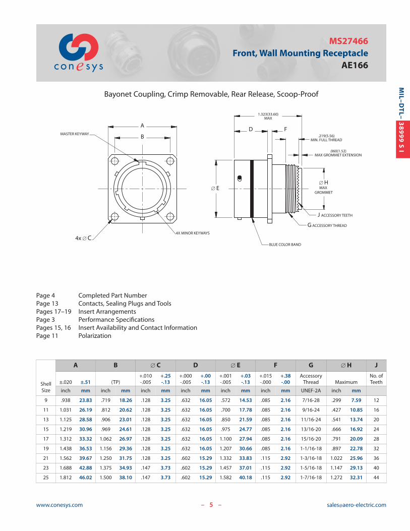
MS27466Front, Wall Mounting Receptacle
AE166
Bayonet Coupling, Crimp Removable, Rear Release, Scoop-Proof
– –
[ HMAX
GROMMET
B
A
4x [ C
MASTER KEYWAY
[ E
BLUE COLOR BAND
J ACCESSORY TEETH
G ACCESSORY THREAD
1.323(33.60)MAX
D.219(5.56)
MIN. FULL THREAD
.060(1.52)MAX GROMMET EXTENSION
F
4X MINOR KEYWAYS
Page 4 Completed Part NumberPage 13 Contacts, Sealing Plugs and ToolsPages 17–19 Insert ArrangementsPage 3 Performance SpecificationsPages 15, 16 Insert Availability and Contact InformationPage 11 Polarization
ShellSize
A B � C D � E F G � H J
+.010 +.25 +.000 +.00 +.001 +.03 +.015 +.38 Accessory No. of±.020 ±.51 (TP) -.005 -.13 -.005 -.13 -.005 -.13 -.000 -.00 Thread Maximum Teeth
inch mm inch mm inch mm inch mm inch mm inch mm UNEF-2A inch mm
9 .938 23.83 .719 18.26 .128 3.25 .632 16.05 .572 14.53 .085 2.16 7/16-28 .299 7.59 12
11 1.031 26.19 .812 20.62 .128 3.25 .632 16.05 .700 17.78 .085 2.16 9/16-24 .427 10.85 16
13 1.125 28.58 .906 23.01 .128 3.25 .632 16.05 .850 21.59 .085 2.16 11/16-24 .541 13.74 20
15 1.219 30.96 .969 24.61 .128 3.25 .632 16.05 .975 24.77 .085 2.16 13/16-20 .666 16.92 24
17 1.312 33.32 1.062 26.97 .128 3.25 .632 16.05 1.100 27.94 .085 2.16 15/16-20 .791 20.09 28
19 1.438 36.53 1.156 29.36 .128 3.25 .632 16.05 1.207 30.66 .085 2.16 1-1/16-18 .897 22.78 32
21 1.562 39.67 1.250 31.75 .128 3.25 .602 15.29 1.332 33.83 .115 2.92 1-3/16-18 1.022 25.96 36
23 1.688 42.88 1.375 34.93 .147 3.73 .602 15.29 1.457 37.01 .115 2.92 1-5/16-18 1.147 29.13 40
25 1.812 46.02 1.500 38.10 .147 3.73 .602 15.29 1.582 40.18 .115 2.92 1-7/16-18 1.272 32.31 44

MIL–D
TL–
38999 S I
MS27656Rear, Wall Mounting ReceptacleAE156
Bayonet Coupling, Crimp Removable, Rear Release, Scoop-Proof
Page 4 Completed Part NumberPage 13 Contacts, Sealing Plugs and ToolsPages 17–19 Insert ArrangementsPage 3 Performance SpecificationsPages 15, 16 Insert Availability and Contact InformationPage 11 Polarization Note: See page 12 for panel thickness.
[ HMAX
GROMMET
J ACCESSORY TEETH
.219 (5.56)MIN FULL THREAD
.060 (1.52)MAX GROMMET EXTENSION
G ACCESSORY THREAD
B
A
4x [ C
MASTER KEYWAY
[ E
BLUE COLOR BAND
1.350 (34.29)MAX
D F
4X MINOR KEYWAYS
ShellSize
A B � C D � E F G � H J
+.010 +.25 +.000 +.00 +.001 +.03 +.015 +.38 Accessory No. of±.020 ±.51 (TP) -.005 -.13 -.005 -.13 -.005 -.13 -.000 -.00 Thread Maximum Teeth
inch mm inch mm inch mm inch mm inch mm inch mm UNEF-2A inch mm
9 .938 23.83 .719 18.26 .128 3.25 .820 20.83 .572 14.53 .085 2.16 7/16-28 .299 7.59 12
11 1.031 26.19 .812 20.62 .128 3.25 .820 20.83 .700 17.78 .085 2.16 9/16-24 .427 10.85 16
13 1.125 28.58 .906 23.01 .128 3.25 .820 20.83 .850 21.59 .085 2.16 11/16-24 .541 13.74 20
15 1.219 30.96 .969 24.61 .128 3.25 .820 20.83 .975 24.77 .085 2.16 13/16-20 .666 16.92 24
17 1.312 33.32 1.062 26.97 .128 3.25 .820 20.83 1.100 27.94 .085 2.16 15/16-20 .791 20.09 28
19 1.438 36.53 1.156 29.36 .128 3.25 .820 20.83 1.207 30.66 .085 2.16 1-1/16-18 .897 22.78 32
21 1.562 39.67 1.250 31.75 .128 3.25 .790 20.07 1.332 33.83 .115 2.92 1-3/16-18 1.022 25.96 36
23 1.688 42.88 1.375 34.93 .147 3.73 .790 20.07 1.457 37.01 .115 2.92 1-5/16-18 1.147 29.13 40
25 1.812 46.02 1.500 38.10 .147 3.73 .790 20.07 1.582 40.18 .115 2.92 1-7/16-18 1.272 32.31 44
www.conesys.com [email protected]– –
7www.conesys.com [email protected]
MIL–D
TL–
38999 S I
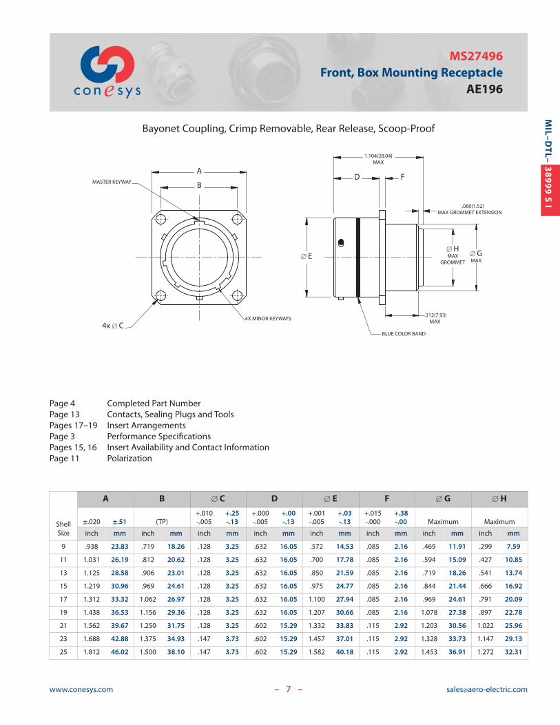
MS27496Front, Box Mounting Receptacle
AE196
Bayonet Coupling, Crimp Removable, Rear Release, Scoop-Proof
Page 4 Completed Part NumberPage 13 Contacts, Sealing Plugs and ToolsPages 17–19 Insert ArrangementsPage 3 Performance SpecificationsPages 15, 16 Insert Availability and Contact InformationPage 11 Polarization
[ HMAX
GROMMET[ GMAX
.312(7.93)MAX
.060(1.52)MAX GROMMET EXTENSION
B
A
4x [ C
MASTER KEYWAY
[ E
BLUE COLOR BAND
1.104(28.04)MAX
FD
4X MINOR KEYWAYS
– –
ShellSize
A B � C D � E F � G � H
+.010 +.25 +.000 +.00 +.001 +.03 +.015 +.38±.020 ±.51 (TP) -.005 -.13 -.005 -.13 -.005 -.13 -.000 -.00 Maximum Maximum
inch mm inch mm inch mm inch mm inch mm inch mm inch mm inch mm
9 .938 23.83 .719 18.26 .128 3.25 .632 16.05 .572 14.53 .085 2.16 .469 11.91 .299 7.59
11 1.031 26.19 .812 20.62 .128 3.25 .632 16.05 .700 17.78 .085 2.16 .594 15.09 .427 10.85
13 1.125 28.58 .906 23.01 .128 3.25 .632 16.05 .850 21.59 .085 2.16 .719 18.26 .541 13.74
15 1.219 30.96 .969 24.61 .128 3.25 .632 16.05 .975 24.77 .085 2.16 .844 21.44 .666 16.92
17 1.312 33.32 1.062 26.97 .128 3.25 .632 16.05 1.100 27.94 .085 2.16 .969 24.61 .791 20.09
19 1.438 36.53 1.156 29.36 .128 3.25 .632 16.05 1.207 30.66 .085 2.16 1.078 27.38 .897 22.78
21 1.562 39.67 1.250 31.75 .128 3.25 .602 15.29 1.332 33.83 .115 2.92 1.203 30.56 1.022 25.96
23 1.688 42.88 1.375 34.93 .147 3.73 .602 15.29 1.457 37.01 .115 2.92 1.328 33.73 1.147 29.13
25 1.812 46.02 1.500 38.10 .147 3.73 .602 15.29 1.582 40.18 .115 2.92 1.453 36.91 1.272 32.31
8www.conesys.com [email protected]
MIL–D
TL–
38999 S I
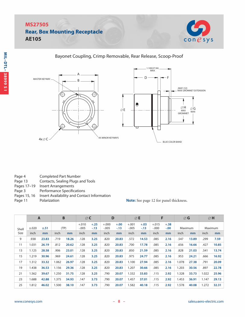
MS27505Rear, Box Mounting ReceptacleAE105
Bayonet Coupling, Crimp Removable, Rear Release, Scoop-Proof
– –
Page 4 Completed Part NumberPage 13 Contacts, Sealing Plugs and ToolsPages 17–19 Insert ArrangementsPage 3 Performance SpecificationsPages 15, 16 Insert Availability and Contact InformationPage 11 Polarization
[ HMAX
GROMMET
[ GMAX
.060(1.52)MAX GROMMET EXTENSION
B
A
4x [ C
MASTER KEYWAY
[ E
BLUE COLOR BAND
1.100(27.94)MAX
D F
4X MINOR KEYWAYS
ShellSize
A B � C D � E F � G � H
+.010 +.25 +.000 +.00 +.001 +.03 +.015 +.38±.020 ±.51 (TP) -.005 -.13 -.005 -.13 -.005 -.13 -.000 -.00 Maximum Maximum
inch mm inch mm inch mm inch mm inch mm inch mm inch mm inch mm
9 .938 23.83 .719 18.26 .128 3.25 .820 20.83 .572 14.53 .085 2.16 .547 13.89 .299 7.59
11 1.031 26.19 .812 20.62 .128 3.25 .820 20.83 .700 17.78 .085 2.16 .656 16.66 .427 10.85
13 1.125 28.58 .906 23.01 .128 3.25 .820 20.83 .850 21.59 .085 2.16 .828 21.03 .541 13.74
15 1.219 30.96 .969 24.61 .128 3.25 .820 20.83 .975 24.77 .085 2.16 .953 24.21 .666 16.92
17 1.312 33.32 1.062 26.97 .128 3.25 .820 20.83 1.100 27.94 .085 2.16 1.078 27.38 .791 20.09
19 1.438 36.53 1.156 29.36 .128 3.25 .820 20.83 1.207 30.66 .085 2.16 1.203 30.56 .897 22.78
21 1.562 39.67 1.250 31.75 .128 3.25 .790 20.07 1.332 33.83 .115 2.92 1.328 33.73 1.022 25.96
23 1.688 42.88 1.375 34.93 .147 3.73 .790 20.07 1.457 37.01 .115 2.92 1.453 36.91 1.147 29.13
25 1.812 46.02 1.500 38.10 .147 3.73 .790 20.07 1.582 40.18 .115 2.92 1.578 40.08 1.272 32.31
Note: See page 12 for panel thickness.

9www.conesys.com [email protected]
MIL–D
TL–
38999 S I
MS27468Jam Nut Receptacle
AE168
Bayonet Coupling, Crimp Removable, Rear Release, Scoop-Proof
– –
Page 4 Completed Part NumberPage 13 Contacts, Sealing Plugs and ToolsPages 17–19 Insert ArrangementsPage 3 Performance SpecificationsPages 15, 16 Insert Availability and Contact InformationPage 11 Polarization
PANEL THICKNESS.125(3.18).062(1.57)
[ D
3X BAYONET PINSEQUALLY SPACED
MASTER KEYWAY
E
BLUE COLOR BAND4X MINOR KEYWAYS
"O"-RING
KFLAT
[ A
HEX NUTPER MS3186
J THREAD
1.308 (33.22)MAX
.615 (15.62)
.598 (15.19)
.920 (23.37)
.910 (23.11)
BLUE COLOR BAND
G No. OF TEETH
F ACCESSORY THREAD
[ C MAX
GROMMET
.060 (1.52) MAXGROMMET EXTENSION
B
ShellSize
� A B � C � D E F G J K
+.001 +.03 +.011 +.28 Accessory No. of Jam Nut Thread Flat-.005 -.13 -.010 -.25 Maximum ±.016 ±.41 ±.016 ±.41 Thread Teeth Class 2A ±.005 ±.13
inch mm inch mm inch mm inch mm inch mm UNEF- 2A inch mm
9 .572 14.53 .109 2.77 .299 7.59 1.188 30.18 1.062 26.97 7/16-28 12 11/16-24UNEF .650 16.51
11 .700 17.78 .109 2.77 .427 10.85 1.375 34.93 1.250 31.75 9/16-24 16 13/16-20UNEF .750 19.05
13 .850 21.59 .109 2.77 .541 13.74 1.500 38.10 1.375 34.93 11/16-24 20 1-20UNEF .937 23.80
15 .975 24.77 .109 2.77 .666 16.92 1.625 41.28 1.500 38.10 13/16-20 24 1-1/8-18UNEF 1.061 26.95
17 1.100 27.94 .109 2.77 .791 20.09 1.750 44.45 1.625 41.28 15/16-20 28 1-1/4-18UNEF 1.186 30.12
19 1.207 30.66 .140 3.56 .897 22.78 1.938 49.23 1.812 46.02 1-1/16-18 32 1-3/8-18UNEF 1.311 33.30
21 1.332 33.83 .140 3.56 1.022 25.96 2.062 52.37 1.938 49.23 1-3/16-18 36 1-1/2-18UNEF 1.436 36.47
23 1.457 37.01 .140 3.56 1.147 29.13 2.188 55.58 2.062 52.37 1-5/16-18 40 1-5/8-18UNEF 1.561 39.65
25 1.582 40.18 .140 3.56 1.272 32.31 2.312 58.72 2.188 55.58 1-7/16-18 44 1-3/4-18UNS 1.686 42.82

10www.conesys.com [email protected]
MIL–D
TL–
38999 S I
MS27467RFI Grounding PlugAE167
Bayonet Coupling, Crimp Removable, Rear Release, Scoop-Proof
– –
Page 4 Completed Part NumberPage 13 Contacts, Sealing Plugs and ToolsPages 17–19 Insert ArrangementsPage 3 Performance SpecificationsPages 15, 16 Insert Availability and Contact InformationPage 11 Polarization
GROMMET EXTENSION
D No. OF TEETH
[ AMIN [ C
MAXGROMMET
[ F MAX.COUPLING NUT
E ACCESSORY THREAD
.219(5.56) MINFULL THREAD
BLUE COLOR BAND
4 MINOR KEYS
MASTER KEY
RFI STRIP
1.294(32.87)
MAX
.060(1.52)MAX
ShellSize
� A � C D E � F
No. of Accessory ThreadMinimum Maximum Teeth Class 2A Maximum
inch mm inch mm inch mm
9 .417 10.59 .299 7.59 12 7/16-28UNEF .859 21.82
11 .545 13.84 .427 10.85 16 9/16-24UNEF .984 24.99
13 .657 16.69 .541 13.74 20 11/16-24UNEF 1.156 29.36
15 .782 19.86 .666 16.92 24 13/16-20UNEF 1.281 32.54
17 .907 23.04 .791 20.09 28 15/16-20UNEF 1.406 35.71
19 1.012 25.70 .897 22.78 32 1-1/16-18UNEF 1.516 38.51
21 1.137 28.88 1.022 25.96 36 1-3/16-18UNEF 1.641 41.68
23 1.262 32.05 1.147 29.13 40 1-5/16-18UNEF 1.766 44.86
25 1.387 35.23 1.272 32.31 44 1-7/16-18UNEF 1.891 48.03

11www.conesys.com [email protected]
MIL–D
TL–
38999 S I
MIL-DTL-38999Polarization
Series I
– –
Keying Positions
Notes:1. Mating face of receptacle shown (plug is opposite).2. The master keyway (key) has various positions relative to
DATUM F; the minor keyways (keys) remain fixed asshown. In the Normal position, the master keyway (key)is at 95° from DATUM F.
3. The angles for a given connector are the same whether itcontains pin or socket inserts.
4. The insert arrangement does not rotate relative to masterkeyway (key).
DATUM F
D°
N°A°
C°
B°
MASTERKEYWAY
NORMAL
5°
ShellSize
Keying Positions
BSC
N° A° B° C° D°9 95 77 – – 113
11 95 81 67 123 109
13 95 75 63 127 115
15 95 74 61 129 116
17 95 77 65 125 113
19 95 77 65 125 113
21 95 77 65 125 113
23 95 80 69 121 110
25 95 80 69 121 110

12www.conesys.com [email protected]
MIL–D
TL–
38999 S I
MIL-DTL-38999 Series IFlange and Jam Nut ReceptaclesPanel Cutouts
Panel Cutouts
– –
Flange and Jam Nut Mounting Dimensions
ShellSize
A � B � C D E � F
+.000 +.00 +.010 +.25(TP) Minimum ±.005 ±.13 Maximum -.010 -.25 -.000 -.00
inch mm inch mm inch mm inch mm inch mm inch mm
9 .719 18.26 .656 16.66 .128 3.25 .234 5.94 .670 17.02 .700 17.78
11 .812 20.62 .796 20.22 .128 3.25 .234 5.94 .771 19.59 .825 20.96
13 .906 23.01 .922 23.42 .128 3.25 .234 5.94 .955 24.26 1.010 25.65
15 .969 24.61 1.047 26.59 .128 3.25 .234 5.94 1.085 27.56 1.135 28.83
17 1.062 26.97 1.219 30.96 .128 3.25 .234 5.94 1.210 30.73 1.260 32.01
19 1.156 29.36 1.297 32.94 .128 3.25 .234 5.94 1.335 33.91 1.385 35.18
21 1.250 31.75 1.422 36.12 .128 3.25 .204 5.18 1.460 37.08 1.510 38.35
23 1.375 34.93 1.547 39.29 .154 3.91 .204 5.18 1.585 40.26 1.635 41.53
25 1.500 38.10 1.672 42.47 .154 3.91 .193 4.90 1.710 43.43 1.760 44.70
A[ F
4x [ C
FLANGE MOUNT
[ BMIN
D MAXPANEL THICKNESS
.125(3.18)
.062(1.57)PANEL THICKNESS
JAM NUT
E
Note 1: Flange Mounting Dimensions (� B cutout and D MAX) listed only for back of panel mounting (MS27505and MS27656).
Note 2: D MAX includes mounting hardware.

13www.conesys.com [email protected]
MIL–D
TL–
38999 S I
MIL-DTL-38999Contacts, Tools and Seal Plugs
Series I
Contacts, Plastic Insertion/Removal Tools and Seal Plugs
Crimping and Metal Insertion/Extraction Tools
Contact and Wire Data
– –
Contact Size
Application Pin Contacts Socket Contacts Seal Plugs Insertion/Removal ToolsPlastic
Type Military No. Military No. Military No. Military No.
22D Power/Signal M39029/58-360 M39029/56-348
MS27488-22-1M81969/14-01
22M* Power/Signal M39029/58-361 M39029/56-349
22* Power/Signal M39029/58-362 M39029/56-350 —
20 Power/Signal M39029/58-363 M39029/56-351 MS27488-20-1 M81969/14-10
16 Power/Signal M39029/58-364 M39029/56-352 MS27488-16-1 M81969/14-03
12 Power/Signal M39029/58-365 M39029/56-353
MS27488-12-1 M81969/14-0412 Coax Coax M39029/28-211 M39029/75-416
12 Coax Coax M39029/102-558 M39029/103-559
8 Coax Coax M39029/60-367 M39029/59-366 MS27488-8-1 M81969/14-06
8 Twinax Twinax M39029/90-529 M39029/91-530 MS27488-8-1 M81969/14-12
ContactSize/Type
Crimp Tool Positioner Positioner Insertion Tool Extraction ToolFor Pin Contacts For Socket Contacts Metal Metal
Military No. Military No. Military No. Military No. Military No.
22D, 22M* M22520/2-01 M22520/2-09 M22520/2-07 M81969/8-01 M81969/8-02
22* M22520/2-01 M22520/2-09 M22520/2-07 M81969/8-03 M81969/8-04
20M22520/1-01 M22520/1-04 M22520/1-04
M81969/8-05 M81969/8-06M22520/2-01 M22520/2-10 M22520/2-10
16 M22520/1-01 M22520/1-04 M22520/1-04 M81969/8-07 M81969/8-08
12 M22520/1-01 M22520/1-04 M22520/1-04
M81969/8-09 M81969/8-1012 Coax Inner M22520/2-01 M22520/2-34 M22520/2-34
12 Coax Outer M22520/31-01 M22520/31-02 M22520/31-02
8 Coax Inner M22520/2-01 M22520/2-31 M22520/2-31
M81969/8-13** M81969/8-148 Coax Outer M22520/5-01
M22520/5-05 M22520/5-05
Die Closure B Die Closure B
8 Twinax Center M22520/2-01 M22520/2-37 M22520/2-37
— —8 Twinax Outer & Intermediate
M22520/5-01 M22520/5-200 M22520/5-200
Contact Size
Test Current Voltage Crimp Well Data Wire Range Finished Wire � RangeDC Test Max. Drop Well Dia. Minimum Well Dept Minimum Maximum
Amps Millivolts inch inch mm AWG mm2 inch mm inch mm
22D 5.0 73 .0345 ±.0010 .141 3.58 28-22 .08-.33 .030 .76 .054 1.37
22M* 3.0 45 .028 ±.001 .141 3.58 28-24 .08-.20 .030 .76 .050 1.27
22* 5.0 73 .0365 ±.0010 .141 3.58 26-22 .13-.33 .034 .86 .060 1.52
20 7.5 55 .047 ±.001 .209 5.31 24-20 .20-.52 .040 1.02 .083 2.11
16 13.0 49 .067 ±.001 .209 5.31 20-16 .52-1.31 .065 1.65 .109 2.77
12 23.0 42 .100 ±.002 .209 5.31 14-12 2.08-3.31 .097 2.46 .142 3.61
* Inactive for new design** Insertion tool is not required.
Note 1: Test Current and Maximum Voltage Drop whentested with silver-plated wire at 25°C.
Note 2: Size 12 coax contacts purchased in bulk.
Note 3: Size 8 coax contacts are used with M17/095-RG180cable, while size 8 Twinax contacts are used with M17/176-00002 cable.

14www.conesys.com [email protected]
MIL–D
TL–
38999 S I
MIL-DTL-38999Contact Installation InstructionsSeries I
– –
Contact InstallationInstructions
Crimping Contacts 1. Select the appropriate crimp tool and ensure that the
proper crimp head positioner is used.
2. Cycle the tool to be sure the indentors are open.
3. Determine the correct selector setting for the wire sizefrom the data plate on the positioner (turret head assembly) and set the selector knob on the crimp tool to match.
4. Place the contact, mating end first, into the tool.
5. Insert the stripped wire into the hollow end of the contact. Be sure the wire is inserted as far as it will go.
6. Close the tool completely to crimp. Unless the tool isclosed completely, the tool will not release the contact.
7. Remove the crimped contact from the tool. Check theinspection hole to verify that the wire is fully inserted.
Insertion of Contacts1. Before inserting the contacts, unscrew the accessories
(clamps, backshells or adapters) from rear of plug orrecep tacle. Slide the hardware over the wire bundle in the proper order for reassembly after all the contacts are inserted.
2. To assist insertion of contacts, lubricate insulator (grommet) cavities with isopropyl alcohol. Alcohol willevaporate and will not leave a conductive film. Caution:Never use any lubricant other than isopropyl alcohol.
3. Place the correct insertion tool on the contact so that thewire runs along the groove in the tool. (Tool tip will buttagainst the shoulder.) Hold the plug or receptacle bodyfirmly.
4. Beginning with a center cavity, insert the contact into theinsulator with a slow, even pressure until the contactsnaps into position. Make sure the contact and tool areheld perpendicular to the face of the insert during thecontact installation or the grommet could be damaged.
4.1 If contacts are not inserted all the way prior toremoving insertion tool, do not try to reinsert theinsertion tool. Instead, remove the contact and tryagain; otherwise reinserting the insertion tool maydamage the inside of the contact cavity.
5. Remove tool and check the face of the connector forproper contact installation. Proper installation may alsobe checked by pulling back lightly on the wire to makesure the contact is properly seated.
CompletionAfter all the cavities have been filled, slide the hardware backinto position on the connector and tighten.
Extraction of Contacts (Rework)1. Slide the hardware back over the wire bundle.
2. Select the appropriate tool. Place the wire into theextraction tool of the pin or socket.
3. Slowly slide the extraction tool down wire into the contact cavities until the tool tip bottoms against thecontact shoulder, expanding the clip retaining tines. Holdthe wire firmly in the tool and pull the wired contact andtool straight out of the rear of the insulator.
Size Pin Contact Socket Contact Basic Crimp Tool Pin Positioner Socket Positioner Insertion/Removal Tool
22D M39029/58-360 M39029/56-348 M22520/2-01 M22520/2-09 M22520/2-07 M81969/14-01
22M M39029/58-361 M39029/56-349 M22520/2-01 M22520/2-09 M22520/2-07 M81969/14-01
22 M39029/58-362 M39029/56-350 M22520/2-01 M22520/2-09 M22520/2-07 M81969/14-01
20 M39029/58-363 M39029/56-351M22520/1-01 M22520/1-04 Red M22520/1-04 Red
M81969/14-10M22520/2-01 M22520/2-10 M22520/2-10
16 M39029/58-364 M39029/56-352 M22520/1-01 M22520/1-04 Blue M22520/1-04 Blue M81969/14-03
12 M39029/58-365 M39029/56-353 M22520/1-01 M22520/1-04 Yellow M22520/1-04 Yellow M81969/14-04
For coax and twinax contacts refer to instructions that are supplied with contacts.

Please see next page for Shell Sizes 21/20/G thru25/24/J layouts.
15www.conesys.com [email protected]
MIL–D
TL–
38999 S I
MIL-DTL-38999 Series I, II and IIIInsert Availability and Contact Information
per MIL-STD-1560
Insert Availability and Contact Information
– –
Insert Arrangement
Aero-Electric Service Total Quantity of ContactsStatus No. of (by Size)
Series I Series II Series III QPL’d Tooled Rating Contacts 22D 22M 22 20 16 12 10 8
9-6* 8-6* — Yes Yes M 6 6
9-35 8-35 A35 Yes Yes M 6 6
9-98 8-98 A98 Yes Yes I 3 3
11-2 — B2 Yes Yes I 2 2
11-4 — B4 Yes Yes I 4 4
11-5 10-5 B5 Yes Yes I 5 5
11-13* 10-13* — Yes Yes M 13 13
11-35 10-35 B35 Yes Yes M 13 13
11-98 10-98 B98 Yes Yes I 6 6
11-99 10-99 B99 Yes Yes I 7 7
— 12-3 — Yes Yes II 3 3
13-4 12-4 C4 Yes Yes I 4 4
13-8 12-8 C8 Yes Yes I 8 8
13-22* 12-22* — Yes Yes M 22 22
13-35 12-35 C35 Yes Yes M 22 22
13-98 12-98 C98 Yes Yes I 10 10
15-5 14-5 D5 Yes Yes II 5 5
15-15 14-15 D15 Yes Yes I 15 14 1
15-18 14-18 D18 Yes Yes I 18 18
15-19 — D19 Yes Yes I 19 19
15-35 14-35 D35 Yes Yes M 37 37
15-37* 14-37* — Yes Yes M 37 37
15-97 14-97 D97 Yes Yes I 12 8 4
17-6 16-6 E6 Yes Yes I 6 6
17-8 16-8 E8 Yes Yes II 8 8
17-26 16-26 E26 Yes Yes I 26 26
17-35 16-35 E35 Yes Yes M 55 55
17-55* 16-55* — Yes Yes M 55 55
17-99 16-99 E99 Yes Yes I 23 21 2
19-11 18-11 F11 Yes Yes II 11 11
19-28 18-28 F28 Yes Yes I 28 26 2
19-30 18-30 F30 Yes Yes I 30 29 1
19-32 18-32 F32 Yes Yes I 32 32
19-35 18-35 F35 Yes Yes M 66 66
— 18-53** — Yes Yes M 53 53
19-66* 18-66* — Yes Yes M 66 66
* Not approved for new design. Tooled and qualified but their separatepictorials are not shown on pages 17 thru 19, as they are the same ascorresponding (-35) layouts that take same qty of 22D instead of 22Mcontacts.
** Not approved for new design. Pictorial is shown on page 18.
— above means “not available” for that series.
38999 S II
38999 S III

16www.conesys.com [email protected]
MIL–D
TL–
38999 S I
MIL-DTL-38999 Series I, II and IIIInsert Availability and Contact Informationper MIL-STD-1560
Insert Availability and Contact Information (continued)
– –
Insert Arrangement
Aero-Electric Service Total Quantity of Contacts
Status No. of (by Size)
Series I Series II Series III QPL’d Tooled Rating Contacts 22D 22M 22 20 16 12 10 8
21-1* 20-1* — Yes Yes M 79 79
21-11 — G11 Yes Yes I 11 11
21-16 20-16 G16 Yes Yes II 16 16
21-35 20-35 G35 Yes Yes M 79 79
21-39 20-39 G39 Yes Yes I 39 37 2
21-41 20-41 G41 Yes Yes I 41 41
21-48** — G48** N/A Yes I 4 4 (Power)
21-75 — G75 Yes Yes Twinax 4 4 (Twinax)
23-1* 22-1* — Yes Yes M 100 100
23-2*** 22-2*** — Yes Yes M 85 85
23-21 22-21 H21 Yes Yes II 21 21
23-32 22-32 H32 Yes Yes I 32 32
23-35 22-35 H35 Yes Yes M 100 100
23-53 22-53 H53 Yes Yes I 53 53
23-55 22-55 H55 Yes Yes I 55 55
25-1* 24-1* — Yes Yes M 128 128
25-4 24-4 J4 Yes Yes I 56 48 8
— — J8 Yes Yes Twinax 8 8 (Twinax)
— — J11 Yes Yes N 11 2 9
25-19 24-19 J19 Yes Yes I 19 19
— — J20 Yes Yes N, Coax, Twinax 30 10 13 4 (Coax) 3 (Twinax)
25-24 24-24 J24 Yes Yes I 24 12 12
25-29 24-29 J29 Yes Yes I 29 29
25-35 24-35 J35 Yes Yes M 128 128
25-43 — J43 Yes Yes I 43 23 20
25-46 — J46**** Yes Yes I, Coax 46 40 4 2 (Coax)
25-61 24-61 J61 Yes Yes I 61 61
— — J90 Yes Yes I, Twinax 46 40 4 2 (Twinax)
* Not approved for new design. Tooled and qualified but their separatepictorials are not shown on pages 17 thru 19, as they are same as corresponding (-35) layouts that take same quantity of 22D instead of 22M contacts.
** 21-48/G48 layout is not to MIL-STD-1560. It is tooled and intended forcomm’l use only.
*** Not approved for new design. Pictorial is shown on page 18.
**** J46 in Series III is not QPL’d but can be purchased to comm’l number(Size 8 Coax contact must be used).
— above means “not available” for that series
Note 1: J20P uses 4 size 12 coax contacts as follows: 2 ea M39029/28-211 and 2 ea of M39029/102-558; J20S uses 4 size 12 coax contacts as follows: 2 ea M39029/75-416 and 2 ea of M39029/103-559.
Note 2: Layouts (G75, J8, J20, J46 and J90) that take twinaxor coax contacts should not be used for firewall applications(Classes K & S) in Series III.
Note 3: H and J contact styles (in lieu of P & S) are meantfor Composite (classes J & M) Series III only. Aluminum(classes A, B, F & W) and Firewall (classes K & S) are ratedfor 500 cycles regardleess what contacts are used.
38999 S II
38999 S III
17www.conesys.com [email protected]
MIL–D
TL–
38999 S I
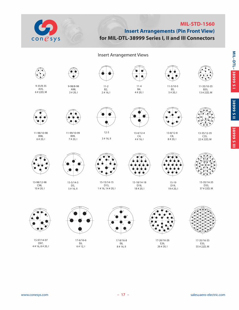
MIL-STD-1560Insert Arrangements (Pin Front View)
for MIL-DTL-38999 Series I, II and III Connectors
Insert Arrangement Views
– –
1
23
4
56
9-35/8-35A35,
6 # 22D, M
A
B
C
9-98/8-98A98,
3 # 20, I
AB
11-2B2,
2 # 16, I
A
BC
D
11-4B4,
4 # 20, I
A
BC
D
E
11-5/10-5B5,
5 # 20, I
12
3
45
67
8
9
10 11
1213
11-35/10-35B35,
13 # 22D, M
A
B
CD
E F
11-98/10-98B98,
6 # 20, I
A
B
CD
E
FG
11-99/10-99B99,
7 # 20, I
A
B
C
12-3
3 # 16, II
A
B
C
D
13-4/12-4C4,
4 # 16, I
A
B
CD
E
F
G
H
13-8/12-8C8,
8 # 20, I
13-35/12-35C35,
22 # 22D, M
AB
C
D
E
F
G
H
JK
13-98/12-98C98,
10 # 20, I
A
B
CD
E
15-5/14-5D5,
5 # 16, II
A
B
C
D
E
F
G
H
J
K
L
MR N
15-15/14-15D15,
1 # 16, 14 # 20, I
A
B
C
D
EFG
H
J
K
L
M N
P
RS
T U
15-18/14-18D18,
18 # 20, I
A B
C
D
E
FG
H
J
K
L
M
N P
R
ST
U V
15-19D19,
19 # 20, I
15-35/14-35D35,
37 # 22D, M
A
B
C
D
EF
G
H
J
K
L
M
15-97/14-97D97,
4 # 16, 8 # 20, I
A
B
C
D
E
F
17-6/16-6E6,
6 # 12, I
A
B
C
DE
F
G
H
17-8/16-8E8,
8 # 16, II
AB
C
D
E
F
G
HJK
LM
N
P
RS T
U
V
WX
Y
Z
a b
c
17-26/16-26E26,
26 # 20, I
17-35/16-35E35,
55 # 22D, M
P
1
3
4
9
10
16
17
24
25
31
32
39
40
46
47
52
53
55
1
15
22
21
14
21
1
31
38999 S II
38999 S III

18www.conesys.com [email protected]
MIL–D
TL–
38999 S I
MIL-STD-1560Insert Arrangements (Pin Front View)for MIL-DTL-38999 Series I, II and III Connectors
Insert Arrangement Views
– –
17-99/16-99E99,
2 # 16, 21 # 20, I
19-11/18-11F11,
11 # 16, II
19-35/18-35F35,
66 #22D, M
18-53*
53 #22, M
21-11G11,
11 # 12, I
21-16/20-16G16,
16 # 16, II
21-75G75,
4 # 8 Twinax, Twinax
A
B
C
D
E
L
F
G
H
J
K
AB
C
D
E
FG
HJK
L
M
N
P
RS T
U
V
W
X
Y Z
19-28/18-28F28,
2 # 16, 26 # 20, I
A
B
C
D
E
F
G
JKL
M
N
P
R
S
T
U
V
W
X
Y
Z
a
b
c
d
e
19-30/18-30F30,
1 # 16, 29 # 20, I
A
B
C
D
E
F
GH
J
K
L
M
N
P
RS
T
U
V
W
X
Y
Z
a
b
c
d
e
fg
1
3
4
9
10
16
17
24
25
33
34
42
43
50
51
57
58
63
64
66
19-32/18-32F32,
32 # 20, I
A
B
C
D
E
F
GJ
HKL
M
N
P
R
S
T
U
V
W
X
Y
Zab
c
d
e
f
g
h
j
A
B
C
DE
F
G
H
J
K
L
A
B
C
D
EF
G
H
J
K
L
M
N
P
R
S
21-41/20-41G41,
41 # 20, I
21-48**G48**,
4 # 8 Power, I
AB
CD
E
F
G
H
J
KLM
N
P
R
S
T
U
V
W
XY
Z
a
b
c
def
g
h
i
j
km
tn
pq
r
s
21-39/20-39G39,
2 # 16, 37 # 20, I
AB
C
D
E
F
G
H
JKL
M
N
P
RS
T
U
VX
YZ
W
a
b
c
de
f
g
h
ij
k
m
n
p
q
r
A
BC
D
A
B
C
D
23-21/22-21H21,
21 # 16, II
23-2*/22-2*
85 # 22, M
A
B
C
D
E
FG
H
J
K
L
M
N
P
R
S
TU
V
W
X
21-35/20-35G35,
79 # 22D, M
1
11
7121
31
41
51
61
79
1
11
21
31
52
51
53
1
4
5
11
12
19
20
28
29
38
39
47
48
57
58
66
67
74
75
81
82
85
* Inactive for new design.
** Not MIL-STD-1560 layout (not QPL’d.).
38999 S II
38999 S III
19www.conesys.com [email protected]
MIL–D
TL–
38999 S I
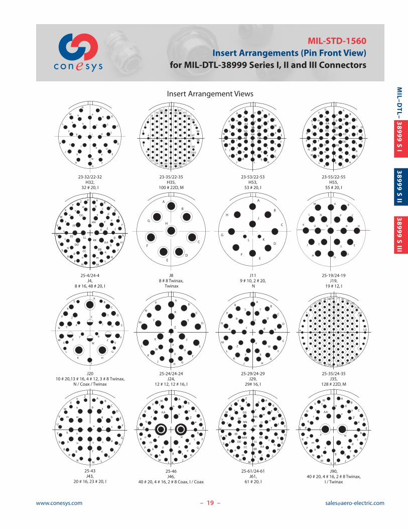
MIL-STD-1560Insert Arrangements (Pin Front View)
for MIL-DTL-38999 Series I, II and III Connectors
Insert Arrangement Views
– –
J88 # 8 Twinax,
Twinax
J119 # 10, 2 # 20,
N
25-24/24-24J24,
12 # 12, 12 # 16, I
23-53/22-53H53,
53 # 20, I
23-35/22-35H35,
100 # 22D, M
AB
C
D
E
F
G
HJ
K
L
M
N
P
RS
T
UV
W
X
Y
Za
bc
d
ef
g
h
km
n
pq
r
s
tu
vw
x
y
z
AABB
CC
DDEE
FF
GGHH
23-55/22-55H55,
55 # 20, I
a
bc
de
fg
H
i
j
km
np
qr
s
t
uv
wx
y
z
AB
C
D
E
F
G
HJK
L
M
N
P
R
S
TU
VW
XY
Z
AA
BB
CC
DDEEFF
GGHH
25-4/24-4J4,
8 # 16, 48 # 20, I
e
AB
CD
E
F
G
H
J
KL
MN
X
YZ
a
bc
d
f
g
h
k
mnP
R
S
T
U
V
W
p
q
r
s
t
uv
w
x
y
z
AA
BBCC
DD
EE
FF
GG
HH
JJ
KKLL
25-19/24-19J19,
19 # 12, I
A B
C
D
E
FGH
J
K
L
M
N P
R
ST
U V
25-43J43,
20 # 16, 23 # 20, I
AB
C
D
E
F
G
H
J
KLM
N
P
R
S
T
U
V
W
XY
Z
a
b
c
d
efg
h
k
m
n p
r
stu
v
w
x
q
25-29/24-29J29,
29# 16, I
AB
C
D
E
F
GHJ
K
L
M
N
P
RS T
U
V
W
XY
Z
a
b c
d
e
f
a
AB
C
D
E
F
GHJ
K
L
M
N
P
R
S
T
UV
W
X
Y
Z
25-46J46,
40 # 20, 4 # 16, 2 # 8 Coax, I / Coax
AB
C
D
E
F
G
H
JKL
M
N
P
R
S
T
U
VW
XY
Za
b
cd
efg
h
k
m
n
p
r
s
t u
v
w
xy
z
AA
q
25-61/24-61J61,
61 # 20, I
A
B
C
D
E
F
G
H
JK
LMN
P
R
S
T
U
V
W
X
YZa b
cd
e
f
g
h
jkm
n
P
r
s
t
uv
w
x
y
z
AABB
CC
DD
EE
FF
GGHH
JJ
KKLL
MM
NNPP
i
q
J90,40 # 20, 4 # 16, 2 # 8 Twinax,
I / Twinax
A
B
C
DE
F
GH
A
B
C
D
EF
G
H
L
J
K
J2010 # 20,13 # 16, 4 # 12, 3 # 8 Twinax,
N / Coax / Twinax
AB
C
D
E
F
G
H
JKL
M
N
P
R
S
T
U
VW
XY
Za
b
cd
efg
h
k
m
n
p
r
s
t u
v
w
xy
z
AA
q
AB
C
D
E
F
G
H
J
K
L
M
N
P
R
S
T
U
VWX
Y
Z
1
23
4
5
67
1
2
3
5
6
8
715
16
24
25
34
35
45
46
55
4
56
66
67
76
77
85
86
93
94
95
9697
98
99
10 0
25-35/24-35J35,
128 # 22D, M
1
4
7
8
14
15
24
25
35
36
47
48
58
59
70
71
81
8294
105
115
122
125
12111 4
10493
23-32/22-32H32,
32 # 20, I
A
B
C
D
E
FG
H
J
K
L
M
N
PR
S
T
U
V
W
X
Y
Z
a
b
c
d
ef
g
h
i
38999 S II
38999 S III

20www.conesys.com [email protected]
MIL–D
TL–
38999 S II
– –
MIL-DTL-38999Features and ApplicationSeries II
www.conesys.com [email protected]
Features and Application
MIL-DTL-38999 Series II connectors feature a bayonet coupling mechanism with lower profile design and rear-removable crimp contact retention system.
These connectors were designed for military and commercialapplications where the prime requirements are lower profileand lighter weight.
Reduction of both size and weight were achieved throughthe use of thinner shell walls and length restrictions. Thesedesign restrictions reduced the RFI attenuation characteristicsand the “scoop” protection, while yielding an excellent gen-eral purpose, lightweight connector. Compared to Series I,Series II connectors achieve up to 20% reduction in matedpair length, up to 39% reduction in outside diameter andup to 40% reduction in weight (128 pin mated pair).
This family of connectors is offered in six receptacle-mountingstyles. They include square flange receptacles, for both frontand rear panel (wall) mounting; square flange receptacles,for both front and rear panel (box) mounting; square flangereceptacle with extended grommet, for front of panel (box)mounting; and jam nut receptacles which incorporate “O” ring seals, designed for rear panel “D” hole mounting.
Plugs are available in two designs, with and without RFIgrounding.
Fifty-two insert arrangement per MIL-STD-1560 are tooledand qualified to MIL-DTL-38999 Series II, utilizing 3 to 128M39029 contacts. Contacts come in sizes 22D, 22M, 22, 20,16 and 12, terminating wire sizes from 28 to 12 gauge.
These connectors are available in wide range of shell materialsand finishes. Aluminum shells are offered in electrolessnickel, bright cadmium, anodized, and olive drab cadmium.Other finishes such as zinc nickel are available upon requestto commercial callouts only. In addition, we offer passivatedstainless steel shells with standard environment-resistinginserts (commercial callouts only).
Universal I/R Tool – A single, expendable plastic tool is usedfor both insertion and removal of contacts.
Closed-Entry Socket Insert – Hard dielectric socket facehas lead-in chamfers for positive alignment of pins (evenpartially bent within pre-established limits) with sockets.
Interfacial Pin Insert Seal – Raised moisture barriersaround each pin, which mate into lead-in chamfers of hardface socket insert, provide individual contact sealing.Interfacial seal is never touched by service tools.
Elastomer Wire Sealing Grommet – Sealing over a widerange of wire diameters is assured by a triple wire seal ineach cavity at the rear of the connector.
Superior Contact Stability – Rear release crimp contactsystem features a stamped beryllium-copper retaining clipcaptivated by molded-in shoulders of each contact cavity inthe insulator. A rear-inserted M81969 plastic tool expandsthe tines beyond the shoulder, releasing the contact.
Shell Polarization – Alternate key/keyway positions preventcross mating of adjacent connectors having same insertarrangement.

21www.conesys.com [email protected]
MIL–D
TL–
38999 S II
MIL-DTL-38999Performance Specifications
Series II
– –
Performance SpecificationsOperating Temperature RangeFinish B: -65°C to +175°C (-85°F to +347°F)Finishes C and F: -65°C to +200°C (-85°F to +392°F)Finish A: -65°C to +150°C (-85°F to 302°F)
Material and Plating Data (Finish)B – aluminum shell, olive drab cadmium over nickel base C – aluminum shell, black anodized finishF – aluminum shell, electroless nickel finishA – aluminum shell, silver to light iridescent yellow color(bright) cadmium over electroless nickel base
Corrosion ResistanceFinishes A, B and C withstand 500-hour salt spray.Finish F withstands 48-hour salt spray.
DurabilityMated connectors withstand a minimum of 250 matingcycles for RFI plug (MS27484) and 500 cycles for MS27473and MS27500 plugs.
Environmental SealWired, mated connectors with specified accessoriesattached, shall meet the altitude-immersion test specified byMIL-DTL-38999.
Fluid ResistanceConnectors resist specified immersions in MIL-PRF-7808,MIL-PRF-23699, MIL-PRF-5606, M2-V Chevron oil, Coolanol25, MIL-DTL-83133 (JP-8), MIL-DTL-5624 (JP-4, JP-5),SAE-AMS1424 Type I, and other solvents and cleaning agents.
Voltage Rating
Shell-to-Shell ConductivityMaximum potential drop shall not exceed:� With RFI spring fingers, finish F = 1.0 millivolt, while
finishes A and B = 2.5 millivolts.� Without spring fingers = 200 millivolts.� Finish C = nonconductive.
Shielding EffectivenessRFI and EMI attenuation at the specified frequencies meetthe requirements of MIL-DTL-38999.� RFI shielding effectiveness of mated connectors with
RFI backshells is measured in a triaxial radio frequencyleakage fixture.
� EMI shielding effectiveness is measured at the interfaceof mated connectors and tested by the mode-stirredtechnique specified in method 3008 of MIL-STD-1344.
Shock and Vibration RequirementsWired, mated connectors shall not be damaged, nor shallthere be a current interruption longer than one microsecondwhen subjected to the following:
Standard ShockMated connectors withstand a pulse of approximate halfsine wave of 300 G magnitude with duration of three milliseconds applied in three axes per MIL-STD-1344,method 2004.
VibrationMated connectors withstand the following vibration levels:� Random vibration per MIL-STD-1344, method 205 test
condition VI, Letter “J”.
ServiceRating
Suggested Operating Voltage Test Voltage Test Voltage Test Voltage Test Voltage
(Sea Level) Sea Level 50,000 Ft. 70,000 Ft. 100,000 Ft.
AC (RMS) DC V RMS V RMS V RMS V RMS
M 400 550 1300 550 350 200
N 300 450 1000 400 260 200
I 600 850 1800 600 400 200
II 900 1250 2300 800 500 200
Note: The establishment of electrical safety factors is leftentirely to the designer, as he is in the best position to know
exactly what peak voltages, switching currents, transients, etc.,can be expected in a particular circuit.

22www.conesys.com [email protected]
MIL–D
TL–
38999 S II
MIL-DTL-38999Part Number DevelopmentSeries II
Military and Aero-Electric Part Number Development
– –
Mil. Prefix MS 27473 T 12 B 35 P A
Aero Prefix AE 273 T 12 B 35 P A -340Shell Type
27472 = Front, wall mount receptacle = 272 (Aero p/n)
27473 = Straight plug = 273 (Aero p/n)
27474 = Jam nut receptacle = 274 (Aero p/n)
27484 = RFI grounding plug = 284 (Aero p/n)
27497 = Rear, wall mount receptacle = 297 (Aero p/n)
27499 = Front, box mount receptacle = 299 (Aero p/n)
27500 = Standard plug with 90˚ backshell = 200 (Aero p/n)
27508 = Rear, box mount receptacle = 208 (Aero p/n)
27513 = Front, box mount rec. (long grommet) = 213 (Aero p/n)
ClassT = With accessory thread (MS27472, 27473, 27474, 27484 & 27497)
E = Same as T in line above except connector is kitted with E-Nut
= No accessory thread, box mount (MS27499 & MS27508)
= No accessory thread, box mount, long grommet (MS27513)
P= Supplied with ring and potting boot (same shell types as “T” class)
Shell Size8, 10, 12, 14, 16, 18, 20, 22 or 24
Finish (Material & Plating)A = Aluminum shell, silver to light iridescent yellow (bright) cadmium over electroless nickel base
B = Aluminum shell, olive drab cadmium over electroless nickel base
C = Aluminum shell, black anodized finish (not available in MS27484)
F = Aluminum shell, electroless nickel finish
E = Stainless steel shell, passivated (Aero p/n only, n/a in AE284)
Insert ArrangementSee page 15 thru 19
Contact DesignatorP = Pin A = Pin connector less pins (with intent to use non-std pin contacts)
S = Socket B = Socket connector less sockets (with intent to use non-std socket contacts)
Polarization (Keying)N = Normal (Omitted in part number)
A, B, C, or D (B & C keyways are not available in shell size 8)
Modification (applies to Aero part numbers only)01 = Less contacts (is not marked on the part)
340 = Connector kitted with M85049/27-XXX E-nut
341 = Connector kitted with M85049/49-2-XXX straight clamp
342 = Connector kitted with M85049/47XXX right angle clamp
Consult factory for other modifications
Note 1: Each connector is furnished with contacts unlessordered less contacts (L/C) as follows: One spare contact forinserts requiring 2 through 26 of each contact and twospares for inserts with 27 or more contacts, and a minimumof one sealing plug up to 10% of the number contacts. One insertion/extraction tool for each contact size is also included.
Note 2: Proper part number marking has no “0” in front of single digit shell size (8) and no “0” in front of singledigit layout. Example of each: J MS27472T8B35S and J MS27472T10B5S. In both “N” for normal is omitted.Please note that JAN or J marking is required immediatelyin front of MS number.
23www.conesys.com [email protected]
MIL–D
TL–
38999 S II
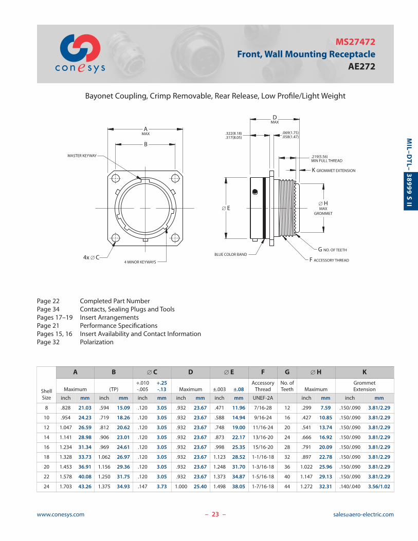
MS27472Front, Wall Mounting Receptacle
AE272
Bayonet Coupling, Crimp Removable, Rear Release, Low Profile/Light Weight
– –
G NO. OF TEETH
F ACCESSORY THREAD4x [ C
MASTER KEYWAY
BLUE COLOR BAND
[ E[ HMAX
GROMMET
K GROMMET EXTENSION
.219(5.56)MIN FULL THREAD
.322(8.18)
.317(8.05)
B
AMAX .069(1.75)
.058(1.47)
DMAX
4 MINOR KEYWAYS
Page 22 Completed Part NumberPage 34 Contacts, Sealing Plugs and ToolsPages 17–19 Insert ArrangementsPage 21 Performance SpecificationsPages 15, 16 Insert Availability and Contact InformationPage 32 Polarization
ShellSize
A B � C D � E F G � H K
+.010 +.25 Accessory No. of GrommetMaximum (TP) -.005 -.13 Maximum ±.003 ±.08 Thread Teeth Maximum Extension
inch mm inch mm inch mm inch mm inch mm UNEF-2A inch mm inch mm
8 .828 21.03 .594 15.09 .120 3.05 .932 23.67 .471 11.96 7/16-28 12 .299 7.59 .150/.090 3.81/2.29
10 .954 24.23 .719 18.26 .120 3.05 .932 23.67 .588 14.94 9/16-24 16 .427 10.85 .150/.090 3.81/2.29
12 1.047 26.59 .812 20.62 .120 3.05 .932 23.67 .748 19.00 11/16-24 20 .541 13.74 .150/.090 3.81/2.29
14 1.141 28.98 .906 23.01 .120 3.05 .932 23.67 .873 22.17 13/16-20 24 .666 16.92 .150/.090 3.81/2.29
16 1.234 31.34 .969 24.61 .120 3.05 .932 23.67 .998 25.35 15/16-20 28 .791 20.09 .150/.090 3.81/2.29
18 1.328 33.73 1.062 26.97 .120 3.05 .932 23.67 1.123 28.52 1-1/16-18 32 .897 22.78 .150/.090 3.81/2.29
20 1.453 36.91 1.156 29.36 .120 3.05 .932 23.67 1.248 31.70 1-3/16-18 36 1.022 25.96 .150/.090 3.81/2.29
22 1.578 40.08 1.250 31.75 .120 3.05 .932 23.67 1.373 34.87 1-5/16-18 40 1.147 29.13 .150/.090 3.81/2.29
24 1.703 43.26 1.375 34.93 .147 3.73 1.000 25.40 1.498 38.05 1-7/16-18 44 1.272 32.31 .140/.040 3.56/1.02

24www.conesys.com [email protected]
MIL–D
TL–
38999 S II
MS27497Rear, Wall Mounting ReceptacleAE297
Bayonet Coupling, Crimp Removable, Rear Release, Low Profile/Light Weight
– –
G NO. OF TEETH
F ACCESSORY THREAD
MASTER KEYWAY
4x [ C BLUE COLOR BAND
[ EMAX
[ HMAX
GROMMET
K GROMMET EXTENSION
.219(5.56)MIN FULL THREAD
B
AMAX .447(11.35)
.442(11.23).069(1.75).058(1.47)
DMAX
4 MINOR KEYWAYS
Page 22 Completed Part NumberPage 34 Contacts, Sealing Plugs and ToolsPages 17–19 Insert ArrangementsPage 21 Performance SpecificationsPages 15, 16 Insert Availability and Contact InformationPage 32 Polarization Note: See page 33 for panel thickness.
ShellSize
A B � C D � E F G � H K
+.010 +.25 Accessory No. of GrommetMaximum (TP) -.005 -.13 Maximum Maximum Thread Teeth Maximum Extension
inch mm inch mm inch mm inch mm inch mm UNEF-2A inch mm inch mm
8 .828 21.03 .594 15.09 .120 3.05 .988 25.10 .547 13.89 7/16-28 12 .299 7.59 .150/.090 3.81/2.29
10 .954 24.23 .719 18.26 .120 3.05 .988 25.10 .672 17.07 9/16-24 16 .427 10.85 .150/.090 3.81/2.29
12 1.047 26.59 .812 20.62 .120 3.05 .988 25.10 .844 21.44 11/16-24 20 .541 13.74 .150/.090 3.81/2.29
14 1.141 28.98 .906 23.01 .120 3.05 .988 25.10 .969 24.61 13/16-20 24 .666 16.92 .150/.090 3.81/2.29
16 1.234 31.34 .969 24.61 .120 3.05 .988 25.10 1.094 27.79 15/16-20 28 .791 20.09 .150/.090 3.81/2.29
18 1.328 33.73 1.062 26.97 .120 3.05 .988 25.10 1.219 30.96 1-1/16-18 32 .897 22.78 .150/.090 3.81/2.29
20 1.453 36.91 1.156 29.36 .120 3.05 .988 25.10 1.344 34.14 1-3/16-18 36 1.022 25.96 .150/.090 3.81/2.29
22 1.578 40.08 1.250 31.75 .120 3.05 .988 25.10 1.469 37.31 1-5/16-18 40 1.147 29.13 .150/.090 3.81/2.29
24 1.703 43.26 1.375 34.93 .147 3.73 1.056 26.82 1.594 40.49 1-7/16-18 44 1.272 32.31 .140/.040 3.56/1.02

25www.conesys.com [email protected]
MIL–D
TL–
38999 S II
MS27499Front, Box Mounting Receptacle
AE299
Bayonet Coupling, Crimp Removable, Rear Release, Low Profile/Light Weight
– –
4x [ C
MASTER KEYWAY
BLUE COLOR BAND
[ E[ FMAX
[ HMAX
GROMMET
.060(1.52)MAXGROMMET EXTENSION
.312(7.92)MAX
.322(8.18)
.317(8.05)B
AMAX
.763(19.38)MAX
.069(1.75)
.058(1.47)
4 MINOR KEYWAYS
Page 22 Completed Part NumberPage 34 Contacts, Sealing Plugs and ToolsPages 17–19 Insert ArrangementsPage 21 Performance SpecificationsPages 15, 16 Insert Availability and Contact InformationPage 32 Polarization
ShellSize
A B � C � E � F � H
+.010 +.25Maximum (TP) -.005 -.13 ±.003 ±.08 Maximum Maximum
inch mm inch mm inch mm inch mm inch mm inch mm
8 .828 21.03 .594 15.09 .120 3.05 .471 11.96 .453 11.51 .299 7.59
10 .954 24.23 .719 18.26 .120 3.05 .588 14.94 .578 14.68 .427 10.85
12 1.047 26.59 .812 20.62 .120 3.05 .748 19.00 .703 17.86 .541 13.74
14 1.141 28.98 .906 23.01 .120 3.05 .873 22.17 .828 21.03 .666 16.92
16 1.234 31.34 .969 24.61 .120 3.05 .998 25.35 .953 24.21 .791 20.09
18 1.328 33.73 1.062 26.97 .120 3.05 1.123 28.52 1.062 26.97 .897 22.78
20 1.453 36.91 1.156 29.36 .120 3.05 1.248 31.70 1.188 30.18 1.022 25.96
22 1.578 40.08 1.250 31.75 .120 3.05 1.373 34.87 1.312 33.32 1.147 29.13
24 1.703 43.26 1.375 34.93 .147 3.73 1.498 38.05 1.438 36.53 1.272 32.31
26www.conesys.com [email protected]
MIL–D
TL–
38999 S II
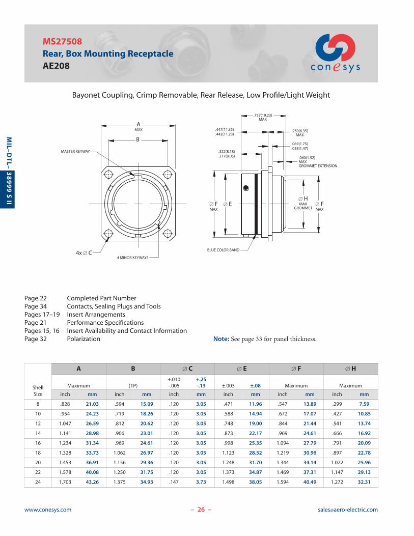
MS27508Rear, Box Mounting ReceptacleAE208
Bayonet Coupling, Crimp Removable, Rear Release, Low Profile/Light Weight
– –
Page 22 Completed Part NumberPage 34 Contacts, Sealing Plugs and ToolsPages 17–19 Insert ArrangementsPage 21 Performance SpecificationsPages 15, 16 Insert Availability and Contact InformationPage 32 Polarization Note: See page 33 for panel thickness.
.058(1.47)
4x [ C
MASTER KEYWAY
BLUE COLOR BAND
.317(8.05)
.322(8.18)
[ FMAX
[ FMAX
[ E[ HMAX
GROMMET
.060(1.52)MAXGROMMET EXTENSION
.442(11.23)
.447(11.35)
B
AMAX
.757(19.23)MAX
.250(6.35)MAX
.069(1.75)
4 MINOR KEYWAYS
ShellSize
A B � C � E � F � H
+.010 +.25Maximum (TP) -.005 -.13 ±.003 ±.08 Maximum Maximum
inch mm inch mm inch mm inch mm inch mm inch mm
8 .828 21.03 .594 15.09 .120 3.05 .471 11.96 .547 13.89 .299 7.59
10 .954 24.23 .719 18.26 .120 3.05 .588 14.94 .672 17.07 .427 10.85
12 1.047 26.59 .812 20.62 .120 3.05 .748 19.00 .844 21.44 .541 13.74
14 1.141 28.98 .906 23.01 .120 3.05 .873 22.17 .969 24.61 .666 16.92
16 1.234 31.34 .969 24.61 .120 3.05 .998 25.35 1.094 27.79 .791 20.09
18 1.328 33.73 1.062 26.97 .120 3.05 1.123 28.52 1.219 30.96 .897 22.78
20 1.453 36.91 1.156 29.36 .120 3.05 1.248 31.70 1.344 34.14 1.022 25.96
22 1.578 40.08 1.250 31.75 .120 3.05 1.373 34.87 1.469 37.31 1.147 29.13
24 1.703 43.26 1.375 34.93 .147 3.73 1.498 38.05 1.594 40.49 1.272 32.31

27www.conesys.com [email protected]
MIL–D
TL–
38999 S II
MS27513Long Grommet, Front, Box Mount Receptacle
AE213
Bayonet Coupling, Crimp Removable, Rear Release, Low Profile/Light Weight
– –
Page 22 Completed Part NumberPage 34 Contacts, Sealing Plugs and ToolsPages 17–19 Insert ArrangementsPage 21 Performance SpecificationsPages 15, 16 Insert Availability and Contact InformationPage 32 Polarization
MASTER KEYWAY
BLUE COLOR BAND
.322(8.18)
.317(8.05).312(7.92)
MAX
.069(1.75)
.058(1.47)B
AMAX
.907(23.04)MAX
.516(13.11)MAX
4x [ C
[ E [ F MAX
[ HMAX
GROMMET
4 MINOR KEYWAYS
ShellSize
A B � C � E � F � H
+.010 +.25Maximum (TP) -.005 -.13 ±.003 ±.08 Maximum Maximum
inch mm inch mm inch mm inch mm inch mm inch mm
8 .828 21.03 .594 15.09 .120 3.05 .471 11.96 .453 11.51 .299 7.59
10 .954 24.23 .719 18.26 .120 3.05 .588 14.94 .578 14.68 .427 10.85
12 1.047 26.59 .812 20.62 .120 3.05 .748 19.00 .703 17.86 .541 13.74
14 1.141 28.98 .906 23.01 .120 3.05 .873 22.17 .828 21.03 .666 16.92
16 1.234 31.34 .969 24.61 .120 3.05 .998 25.35 .953 24.21 .791 20.09
18 1.328 33.73 1.062 26.97 .120 3.05 1.123 28.52 1.062 26.97 .897 22.78
20 1.453 36.91 1.156 29.36 .120 3.05 1.248 31.70 1.188 30.18 1.022 25.96
22 1.578 40.08 1.250 31.75 .120 3.05 1.373 34.87 1.312 33.32 1.147 29.13
24 1.703 43.26 1.375 34.93 .147 3.73 1.498 38.05 1.438 36.53 1.272 32.31

28www.conesys.com [email protected]
MIL–D
TL–
38999 S II
MS27474Jam Nut ReceptacleAE274
Bayonet Coupling, Crimp Removable, Rear Release, Low Profile/Light Weight
– –
3 BAYONET PINS4 MINOR KEYWAYS E THREAD
BLUE COLOR BAND
MASTERKEYWAY
HEX NUTPER MS3186
[ F
D
BFLAT
"O" RINGA
GMAX.
M ACCESSORY THREAD
H NO. OF TEETH
[ JMAX
GROMMET
SS 8-22 .150(3.81).090(2.29)
SS 24 .140(3.56).040(1.02)
.105(2.67)
.084(2.13)
GROMMETEXTENSION
PANEL THICKNESS.109(2.77).062(1.57)
Page 22 Completed Part NumberPage 34 Contacts, Sealing Plugs and ToolsPages 17–19 Insert ArrangementsPage 21 Performance SpecificationsPages 15, 16 Insert Availability and Contact InformationPage 32 Polarization
ShellSize
A B D E � F G H � J M
+.001 +.03 Jam Nut Thread No. of Accessory±.005 ±.13 -.006 -.15 ±.016 ±.41 Class 2A ±.003 ±.08 Maximum Teeth Maximum Thread
inch mm inch mm inch mm inch mm inch mm inch mm UNEF-2A
8 .438 11.13 .817 20.75 1.250 31.75 7/8-20UNEF .471 11.96 .937 23.80 12 .299 7.59 7/16-28
10 .438 11.13 .941 23.90 1.375 34.93 1-20UNEF .588 14.94 .937 23.80 16 .427 10.85 9/16-24
12 .438 11.13 1.065 27.05 1.500 38.10 1-1/8-18UNEF .748 19.00 .937 23.80 20 .541 13.74 11/16-24
14 .438 11.13 1.190 30.23 1.625 41.28 1-1/4-18UNEF .873 22.17 .937 23.80 24 .666 16.92 13/16-20
16 .438 11.13 1.320 33.53 1.781 45.24 1-3/8-18UNEF .998 25.35 .937 23.80 28 .791 20.09 15/16-20
18 .438 11.13 1.440 36.58 1.890 48.01 1-1/2-18UNEF 1.123 28.52 .937 23.80 32 .897 22.78 1-1/16-18
20 .464 11.79 1.565 39.75 2.016 51.21 1-5/8-18UNEF 1.248 31.70 .931 23.65 36 1.022 25.96 1-3/16-18
22 .464 11.79 1.690 42.93 2.140 54.36 1-3/4-18UNS 1.373 34.87 .931 23.65 40 1.147 29.13 1-5/16-18
24 .464 11.79 1.815 46.10 2.265 57.53 1-7/8-16UN 1.498 38.05 .984 24.99 44 1.272 32.31 1-7/16-18

29www.conesys.com [email protected]
MIL–D
TL–
38999 S II
MS27473Straight Plug
AE273
Bayonet Coupling, Crimp Removable, Rear Release, Low Profile/Light Weight
– –
H GROMMET EXTENSION
GMAX
4 MINOR KEYS
BLUE COLOR BAND
[ F MAXCOUPLING NUT
MASTER KEY
[ AMIN
SHELL
[ CMAX
GROMMET
E ACCESSORY THREAD
D NO. OF TEETH
Page 22 Completed Part NumberPage 34 Contacts, Sealing Plugs and ToolsPages 17–19 Insert ArrangementsPage 21 Performance SpecificationsPages 15, 16 Insert Availability and Contact InformationPage 32 Polarization
ShellSize
� A � C D E � F G H
No of Accessory GrommetMinimum Maximum Teeth Thread Maximum Maximum Extension
inch mm inch mm UNEF-2A inch mm inch mm inch mm
8 .337 8.56 .299 7.59 12 7/16-28 .750 19.05 .916 23.27 .150/.090 3.81/2.29
10 .465 11.81 .427 10.85 16 9/16-24 .859 21.82 .916 23.27 .150/.090 3.81/2.29
12 .557 14.15 .541 13.74 20 11/16-24 1.031 26.19 .916 23.27 .150/.090 3.81/2.29
14 .702 17.83 .666 16.92 24 13/16-20 1.156 29.36 .916 23.27 .150/.090 3.81/2.29
16 .827 21.01 .791 20.09 28 15/16-20 1.281 32.54 .916 23.27 .150/.090 3.81/2.29
18 .927 23.55 .897 22.78 32 1-1/16-18 1.406 35.71 .916 23.27 .150/.090 3.81/2.29
20 1.052 26.72 1.022 25.96 36 1-3/16-18 1.531 38.89 .916 23.27 .150/.090 3.81/2.29
22 1.177 29.90 1.147 29.13 40 1-5/16-18 1.641 41.68 .916 23.27 .150/.090 3.81/2.29
24 1.302 33.07 1.272 32.31 44 1-7/16-18 1.766 44.86 .984 24.99 .140/.040 3.56/1.02

30www.conesys.com [email protected]
MIL–D
TL–
38999 S II
MS27484RFI Grounding PlugAE284
Bayonet Coupling, Crimp Removable, Rear Release, Low Profile/Light Weight
– –
R.F.I. GROUNDING SPRING
4 MINOR KEYS
[ F MAXCOUPLING NUT
MASTER KEY
H GROMMET EXTENSION
GMAX
BLUE COLOR BAND
[ AMIN
SHELL
[ CMAX
GROMMET
E UNEF-2A ACCESSORY THREAD
D NO. OF TEETH
Page 22 Completed Part NumberPage 34 Contacts, Sealing Plugs and ToolsPages 17–19 Insert ArrangementsPage 21 Performance SpecificationsPages 15, 16 Insert Availability and Contact InformationPage 32 Polarization
ShellSize
� A � C D E � F G H
No of Accessory GrommetMinimum Maximum Teeth Thread Maximum Maximum Extension
inch mm inch mm UNEF-2A inch mm inch mm inch mm
8 .337 8.56 .299 7.59 12 7/16-28 .750 19.05 .916 23.27 .150/.090 3.81/2.29
10 .465 11.81 .427 10.85 16 9/16-24 .859 21.82 .916 23.27 .150/.090 3.81/2.29
12 .557 14.15 .541 13.74 20 11/16-24 1.031 26.19 .916 23.27 .150/.090 3.81/2.29
14 .702 17.83 .666 16.92 24 13/16-20 1.156 29.36 .916 23.27 .150/.090 3.81/2.29
16 .827 21.01 .791 20.09 28 15/16-20 1.281 32.54 .916 23.27 .150/.090 3.81/2.29
18 .927 23.55 .897 22.78 32 1-1/16-18 1.406 35.71 .916 23.27 .150/.090 3.81/2.29
20 1.052 26.72 1.022 25.96 36 1-3/16-18 1.531 38.89 .916 23.27 .150/.090 3.81/2.29
22 1.177 29.90 1.147 29.13 40 1-5/16-18 1.641 41.68 .916 23.27 .150/.090 3.81/2.29
24 1.302 33.07 1.272 32.31 44 1-7/16-18 1.766 44.86 .984 24.99 .140/.040 3.56/1.02

31www.conesys.com [email protected]
MIL–D
TL–
38999 S II
MS27500Plug with 90° Backshell
AE200
Bayonet Coupling, Crimp Removable, Rear Release, Low Profile/Light Weight
– –
W
L MAX
Y
4 MINOR KEYS
MASTER KEY BLUE COLOR BAND
[ AMIN
[ F MAXCOUPLING NUT
Page 22 Completed Part NumberPage 34 Contacts, Sealing Plugs and ToolsPages 17–19 Insert ArrangementsPage 21 Performance SpecificationsPages 15, 16 Insert Availability and Contact InformationPage 32 Polarization
ShellSize
� A � F L W Y
Minimum Maximum Maximum Maximum Maximum
inch mm inch mm inch mm inch mm inch mm
8 .337 8.56 .750 19.05 1.859 47.22 1.000 25.40 .828 21.03
10 .465 11.81 .859 21.82 1.859 47.22 1.032 26.21 .891 22.63
12 .557 14.15 1.031 26.19 1.938 49.23 1.094 27.79 1.016 25.81
14 .702 17.83 1.156 29.36 2.125 53.98 1.219 30.96 1.141 28.98
16 .827 21.01 1.281 32.54 2.281 57.94 1.281 32.54 1.255 31.88
18 .927 23.55 1.406 35.71 2.312 58.72 1.344 34.14 1.469 37.31
20 1.052 26.72 1.531 38.89 2.375 60.33 1.375 34.93 1.550 39.37
22 1.177 29.90 1.641 41.68 2.531 64.29 1.438 36.53 1.675 42.55
24 1.302 33.07 1.766 44.86 2.828 71.83 1.719 43.66 1.800 45.72

32www.conesys.com [email protected]
MIL–D
TL–
38999 S II
MIL-DTL-38999PolarizationSeries II
Keying Positions
– –
DATUM F
D°
N°A°
C°
B°
MASTER NORMAL
KEYWAY
10°
Notes:1. Mating face of receptacle shown (plug is opposite).2. The master keyway (key) has various positions relative to
DATUM F; the minor keyways (keys) remain fixed asshown. In the Normal position, the master keyway (key)is 100° from DATUM F.
3. The angles for a given connector are the same whether itcontains pin or socket inserts.
4. The insert arrangement does not rotate relative to masterkeyway (key).
ShellSize
Keying Positions
BSC
N° A° B° C° D°8 100 82 - - 118
10 100 86 72 128 114
12 100 80 68 132 120
14 100 79 66 134 121
16 100 82 70 130 118
18 100 82 70 130 118
20 100 82 70 130 118
22 100 85 74 126 115
24 100 85 74 126 115

33www.conesys.com [email protected]
MIL–D
TL–
38999 S II
MIL-DTL-38999 Series IIFlange and Jam Nut Receptacles
Panel Cutouts
Panel Cutouts
– –
A[ E
4x [ C
FLANGE MOUNT
[ BMIN
D MAXPANEL THICKNESS
.109(2.77)
.062(1.57)PANEL THICKNESS
JAM NUT
F
Note 1: Flange Mounting Dimensions (� B cutout and D MAX) listed only for back of panel mounting (MS27497and MS27508).
Flange and Jam Nut Mounting Dimensions
Note 2: D MAX includes mounting hardware.
ShellSize
A � B � C D � E F
+.010 +.25 +.000 +.00(TP) Minimum ±.005 ±.13 Maximum -.000 -.00 -.010 -.25
inch mm inch mm inch mm inch mm inch mm inch mm
8 .594 15.09 .557 14.15 .128 3.25 .146 3.71 .885 22.48 .830 21.08
10 .719 18.26 .682 17.32 .128 3.25 .146 3.71 1.010 25.65 .955 24.26
12 .812 20.62 .854 21.69 .128 3.25 .146 3.71 1.135 28.83 1.085 27.56
14 .906 23.01 .979 24.87 .128 3.25 .146 3.71 1.260 32.01 1.210 30.73
16 .969 24.61 1.104 28.04 .128 3.25 .146 3.71 1.385 35.18 1.335 33.91
18 1.062 26.97 1.229 31.22 .128 3.25 .146 3.71 1.510 38.35 1.460 37.08
20 1.156 29.36 1.354 34.39 .128 3.25 .168 4.27 1.635 41.53 1.585 40.26
22 1.250 31.75 1.479 37.57 .128 3.25 .168 4.27 1.760 44.70 1.709 43.42
24 1.375 34.93 1.604 40.74 .154 3.91 .168 4.27 1.885 47.88 1.835 46.61

34www.conesys.com [email protected]
MIL–D
TL–
38999 S II
MIL-DTL-38999Contacts, Tools and Seal PlugsSeries II
Contacts, Plastic Insertion/Removal Tools and Seal Plugs
Crimping and Metal Insertion/Extraction Tools
Contact and Wire Data
– –
ContactSize
Application Pin Contacts Socket Contacts Seal Plugs Insertion/Removal Tools
Plastic
Type Military No. Military No. Military No. Military No.
22D Power/Signal M39029/58-360 M39029/57-354
MS27488-22-1M81969/14-01
22M* Power/Signal M39029/58-361 M39029/57-355
22* Power/Signal M39029/58-362 M39029/57-356 —
20 Power/Signal M39029/58-363 M39029/57-357 MS27488-20-1 M81969/14-10
16 Power/Signal M39029/58-364 M39029/57-358MS27488-16-1 M81969/14-03
16 Coax Coax M39029/76-424 M39029/78-432
12 Power/Signal M39029/58-365 M39029/57-359 MS27488-12-1 M81969/14-04
ContactSize/Type
Crimp Tool Positioner Positioner Insertion Tool Extraction Tool
For Pin Contacts For Socket Contacts Metal Metal
Military No. Military No. Military No. Military No. Military No.
22D, 22M* M22520/2-01 M22520/2-09 M22520/2-06 M81969/8-01 M81969/8-02
22* M22520/2-01 M22520/2-09 M22520/2-06 M81969/8-03 M81969/8-04
20M22520/1-01 M22520/1-04 M22520/1-04
M81969/8-05 M81969/8-06M22520/2-01 M22520/2-10 M22520/2-10
16 M22520/1-01 M22520/1-04 M22520/1-04
M81969/8-07 M81969/8-0816 Coax Inner M22520/2-01 M22520/2-35 M22520/2-35
16 Coax Outer M22520/4-01 M22520/4-02 M22520/4-02
12 M22520/1-01 M22520/1-04 M22520/1-04 M81969/8-09 M81969/8-10
ContactSize
Test Current Voltage Crimp Well Data Wire Range Finished Wire � Range
DC Test Max. Drop Well Dia. Minimum Well Dept Minimum Maximum
Amps Millivolts inch inch mm AWG mm2 inch mm inch mm
22D 5.0 73 .0345 ±.0010 .141 3.58 28-22 .08-.33 .030 .76 .054 1.37
22M* 3.0 45 .028 ±.001 .141 3.58 28-24 .08-.20 .030 .76 .050 1.27
22* 5.0 73 .0365 ±.0010 .141 3.58 26-22 .13-.33 .034 .86 .060 1.52
20 7.5 55 .047 ±.001 .209 5.31 24-20 .20-.52 .040 1.02 .083 2.11
16 13.0 49 .067 ±.001 .209 5.31 20-16 .52-1.31 .065 1.65 .109 2.77
12 23.0 42 .100 ±.002 .209 5.31 14-12 2.08-3.31 .097 2.46 .142 3.61
* Inactive for new design
Note 1: Test Current and Maximum Voltage Drop whentested with silver-plated wire at 25°C.
Note 2: Size 16 coax contacts purchased in bulk.

35www.conesys.com [email protected]
MIL–D
TL–
38999 S II
MIL-DTL-38999Contact Installation Instructions
Series II
– –
Contact InstallationInstructions
Crimping Contacts 1. Select the appropriate crimp tool and ensure that the
proper crimp head positioner is used.
2. Cycle the tool to be sure the indentors are open.
3. Determine the correct selector setting for the wire sizefrom the data plate on the positioner (turret head assembly) and set the selector knob on the crimp tool to match.
4. Place the contact, mating end first, into the tool.
5. Insert the stripped wire into the hollow end of the contact. Be sure the wire is inserted as far as it will go.
6. Close the tool completely to crimp. Unless the tool isclosed completely, the tool will not release the contact.
7. Remove the crimped contact from the tool. Check theinspection hole to verify that the wire is fully inserted.
Insertion of Contacts1. Before inserting the contacts, unscrew the accessories
(clamps, backshells or adapters) from rear of plug orreceptacle. Slide the hardware over the wire bundle in the proper order for reassembly after all the contacts are inserted.
2. To assist insertion of contacts, lubricate insulator (grommet) cavities with isopropyl alcohol. Alcohol willevaporate and will not leave a conductive film. Caution:Never use any lubricant other than isopropyl alcohol.
3. Place the correct insertion tool on the contact so that thewire runs along the groove in the tool. (Tool tip will buttagainst the shoulder.) Hold the plug or receptacle bodyfirmly.
4. Beginning with a center cavity, insert the contact into the insulator with a slow, even pressure until the contactsnaps into position. Make sure the contact and tool areheld perpendicular to the face of the insert during thecontact installation or the grommet could be damaged.
4.1 If contacts are not inserted all the way prior toremoving insertion tool, do not try to reinsert theinsertion tool. Instead, remove the contact and tryagain; otherwise reinserting the insertion tool maydamage the inside of the contact cavity.
5. Remove tool and check the face of the connector forproper contact installation. Proper installation may alsobe checked by pulling back lightly on the wire to makesure the contact is properly seated.
CompletionAfter all the cavities have been filled, slide the hardware backinto position on the connector and tighten.
Extraction of Contacts (Rework)1. Slide the hardware back over the wire bundle.
2. Select the appropriate tool. Place the wire into theextraction tool of the pin or socket.
3. Slowly slide the extraction tool down wire into the contactcavities until the tool tip bottoms against the contactshoulder, expanding the clip retaining tines. Hold thewire firmly in the tool and pull the wired contact andtool straight out of the rear of the insulator.
Size Pin Contact Socket Contact Basic Crimp Tool Pin Positioner Socket Positioner Insertion/Removal Tool
22D M39029/58-360 M39029/57-354 M22520/2-01 M22520/2-09 M22520/2-06 M81969/14-01
22M M39029/58-361 M39029/57-355 M22520/2-01 M22520/2-09 M22520/2-06 M81969/14-01
22 M39029/58-362 M39029/57-356 M22520/2-01 M22520/2-09 M22520/2-06 M81969/14-01
20 M39029/58-363 M39029/57-357M22520/1-01 M22520/1-04 Red M22520/1-04 Red
M81969/14-10M22520/2-01 M22520/2-10 M22520/2-10
16 M39029/58-364 M39029/57-358 M22520/1-01 M22520/1-04 Blue M22520/1-04 Blue M81969/14-03
12 M39029/58-365 M39029/57-359 M22520/1-01 M22520/1-04 Yellow M22520/1-04 Yellow M81969/14-04
For coax contacts refer to instructions supplied with contacts.

36www.conesys.com [email protected]
MIL–D
TL–
38999 S III
– –
MIL-DTL-38999Features and ApplicationSeries III
www.conesys.com [email protected]
Features and Application
MIL-DTL-38999 Series III is the newest cylindrical connectordesigned for highest performance capabilities used in bothgeneral purpose and severe environment applications.
These connectors feature an improved “one-turn” couplingsystem, utilizing self-locking acme thread. Acme threadsprovide coupling durability, while thicker wall sections andgreater coupling surface area improve strength and shockresistance. Blunting of the threads on both receptacle andplug coupling nut eliminates cross threading.
Elongated mounting holes permit the Series III Connector tointermount with various existing Mil-spec flange mountedreceptacles, giving it a design replacement advantage.
Wall mount receptacle, jam nut receptacle and straight self-locking RFI plug are offered in 9 shell sizes and 54 insertarrangements utilizing M39029 contacts in sizes 22D, 20, 16,12, 10 power and 8 twinax.
These connectors are available in wide range of shell materialsand finishes. Aluminum shells are offered in electroless nickeland olive drab cadmium. Other finishes such as anodic andzinc nickel are available upon request to commercial calloutsonly. In addition, we offer stainless steel shells (both passivatedand electro-deposited nickel plated) with firewall inserts, andfor highly corrosive environments, nickel-aluminum-bronzeshells with standard environment-resisting inserts (commer-cial callouts only).
MIL-STD-1560 Insert Arrangements – Series III connectorsuse insert patterns and contacts common to Series I, making for an easy transition from bayonet to triple-lead,acme-thread, self-locking coupling.
Metal-to-Metal Bottoming – This feature precludes relativeshell-to-shell motion, which may result in ordinary connectorwear and moisture entrapment.
Lockwiring Eliminated – Self-locking quick coupling plugeliminates the need for lockwiring.
Firewall Capability - Stainless steel shells in both K and Sfirewall classes are offered.
Universal I/R Tool – A single, expendable plastic tool is usedfor both insertion and removal of contacts.
Scoop-Proof Design – Recessed pins in elongated shellsminimize the possibility for contact damage. In a blind mating application, mating shells cannot “scoop” the pins,and cause a shorting or bending of contacts.
Closed-Entry Socket Insert – Hard dielectric socket facehas lead-in chamfers for positive alignment of pins (evenpartially bent within pre-established limits) with sockets.
Interfacial Pin Insert Seal – Raised moisture barriersaround each pin, which mate into lead-in chamfers of hard face socket insert, provide individual contact sealing.Interfacial seal is never touched by service tools.
Elastomer Wire Sealing Grommet – Sealing over a widerange of wire diameters is assured by a triple wire seal ineach cavity at the rear of the connector.
Superior Contact Stability – Rear release crimp contactsystem features a stamped beryllium-copper retaining clipcaptivated by molded-in shoulders of each contact cavity inthe insulator. A rear-inserted M81969 plastic tool expandsthe tines beyond the shoulder, releasing the contact.
Metric Accessory Thread – Metric thread results in additional wall thickness giving greater strength and shockresistance.

37www.conesys.com [email protected]
MIL–D
TL–
38999 S III
MIL-DTL-38999Performance Specifications
Series III
– –
Performance SpecificationsOperating Temperature RangeClasses F, K, S and BZ*: -65°C to +200°C (-85°F to +392°F)Classes W and ZC*: -65°C to +175°C (-85°F to +347°F)
Material and Finish Data (Class)F – aluminum shell, electroless nickel finishK – stainless steel shell, passivated, firewallS – stainless steel shell, electrodeposited nickel, firewallW– aluminum shell, olive drab cadmium over nickel baseBZ*– aluminum nickel bronze shell, std insertZ*– aluminum shell, zinc nickel finish
Corrosion ResistanceClasses K, W, BZ* and Z* withstand 500-hour salt spray.Classes F and S withstand 48-hour salt spray.
DurabilityMinimum of 500 mating cycles.
Fluid ResistanceConnectors resist specified immersions in MIL-PRF-7808,MIL-PRF-23699, MIL-PRF-5606, M2-V Chevron oil, Coolanol25, MIL-DTL-83133 (JP-8), MIL-DTL-5624 (JP-4, JP-5),SAE-AMS1424 Type I, and other solvents and cleaning agents.
Shielding EffectivenessRFI and EMI attenuation at the specified frequencies meetthe requirements of MIL-DTL-38999.� RFI shielding effectiveness of mated connectors with RFI
backshells is measured in a triaxial radio frequency leakagefixture.
� EMI shielding effectiveness is measured at the interfaceof mated connectors and tested by the mode-stirredtechnique specified in method 3008 of MIL-STD-1344.
Voltage Rating
Environmental SealWired, mated connectors with specified accessories attached, shall meet the altitude-immersion test specified inMIL-DTL-38999.
Shell-to-Shell ConductivityMaximum potential drop shall not exceed:� Classes F and S = 1.0 millivolt.� Class W = 2.5 millivolts, Class K = 10.0 millivolts
Shock and Vibration RequirementsWired, mated connectors shall not be damaged, nor shallthere be a current interruption longer than one microsecondwhen subjected to the following:
ShockPulse of approximate half sine wave of 300 G ±15 percent mag-nitude with duration of 3±1 milliseconds applied in three axes.
High Impact ShockWhen mounted as specified in MIL-S-901, grade A, a drop of a 400 lb. Hammer from 1 foot, 3 feet and 5 feet applied toconnector in three axes, totaling nine impacts.
VibrationWired and mated connectors withstand the following vibration levels:� Sine vibration where connector samples with simulated
accessory load are subjected to simple harmonic motionfrom 10 to 2,000 Hz in three mutually perpendicular axes,in 20 minute sweeps, for 12 hours in each axis at velocity of254 mm/sec from 10-50 Hz, displacement of 1.5 mm from50-140Hz and acceleration of 60G from 140-2,000Hz.
� Random Vibration per MIL-STD-1344, method 205, test condition V at ambient temperature and test condition VI, Letter “J” at elevated temperature.
* Not on QPL, can be supplied to Aero-Electric part number only.
ServiceRating
Suggested Operating Voltage Test Voltage Test Voltage Test Voltage Test Voltage
(Sea Level) Sea Level 50,000 Ft. 70,000 Ft. 100,000 Ft.
AC (RMS) DC V RMS V RMS V RMS V RMS
M 400 550 1300 550 350 200
N 300 450 1000 400 260 200
I 600 850 1800 600 400 200
II 900 1250 2300 800 500 200
Note: The establishment of electrical safety factors is leftentirely to the designer, as he is in the best position to know
exactly what peak voltages, switching currents, transients, etc.,can be expected in a particular circuit.

38www.conesys.com [email protected]
MIL–D
TL–
38999 S III
MIL-DTL-38999Part Number DevelopmentSeries III
Military and Aero-Electric Part Number Development
– –
* Not on QPL, can be supplied to Aero-Electric part number only.
Note 1: Each connector is furnished with contacts unlessordered less contacts (L/C) as follows: One spare contact forinserts requiring 2 through 26 of each contact and twospares for inserts with 27 or more contacts, and a minimumof one sealing plug up to 10% of the number contacts.Spare Coax and Twinax contacts are not supplied. One insertion/extraction tool for each contact size is also included.
Note 2: Proper part number marking has no “0” in front of single digit layout. Example: JD38999/20WB5SN. “N” fornormal is included. In addition, J or JAN must be markedimmediately in front of MIL part number.
Mil. Prefix D38999/ 20 W C 35 P N
Aero Prefix AE3 20 W C 35 P N -340Shell Type (Specification Sheet Number)
20 = Wall mount receptacle
24 = Jam nut receptacle
26 = Self-locking, RFI grounding plug
Class (Material & Finish)F = Aluminum shell, electroless nickel finish
W = Aluminum shell, olive drab cadmium over electroless nickel base
K = Stainless steel shell, passivated, with firewall insert
S = Stainless steel shell, electrodeposited nickel, with firewall insert
BZ* = Aluminum nickel bronze shell with standard insert (Aero p/n only)
Z* = Aluminum shell, zinc nickel plating (Aero p/n only)
Shell SizeA, B, C, D, E, F, G, H or J
Insert ArrangementSee pages 15 thru 19
Contact StyleP = Pin
S = Socket
A = Pin connector less pins (with intent to use non-std pin contacts)
B = Socket connector less sockets (with intent to use non-std socket contacts)
Polarization (Keying)N = Normal (Included in part number)
A, B, C, D, or E
Modification (applies to Aero part numbers only)01 = Less contacts (is not marked on the part)
340 = Connector kitted with M85049/14-XXX
341 = Connector kitted with M85049/38-XXX straight clamp
342 = Connector kitted with M85049/39-XXX right angle clamp
Consult factory for other modifications

39www.conesys.com [email protected]
MIL–D
TL–
38999 S III
D38999/20Wall Mounting Receptacle
AE320
Triple Start Threaded Coupling, Crimp Removable, Rear Release, Scoop-Proof
– –
BLUE COLOR BAND(REAR RELEASE)
B
4 MINOR KEYWAYS
E
C
D
LOCKING INDICATOR BANDCOLOR: RED
FMATING THREAD
MASTER KEYWAY GMAX
31.50(1.240)MAX
2.16(.085) MAXGROMMET EXTENSION
J NUMBER OF TEETH
K ACCESSORY THREAD
7.11(.280)MIN FULL THREAD
H MAX
A
[ LMAX
GROMMET
Page 38 Completed Part NumberPage 44 Contacts, Sealing Plugs and ToolsPages 17–19 Insert ArrangementsPage 37 Performance SpecificationsPages 15, 16 Insert Availability and Contact InformationPage 42 Polarization
Note 1: “K” Accessory Thread for AE320 is same as AE326(“D” Accessory Thread) on page 41.
Note 2: “F” Mating Thread for AE320 is same as AE326(“E” Mating Thread) on page 41 except it is Class 2A.
Note 3: Maximum Grommet Extension for insert layoutsincorporating size 8 and 10 contacts = 5.95(.234).
ShellSize
A B C D E G H J � L
No. of ±.012 ±.30 (TP) (TP) ±.008 ±.20 ±.008 ±.20 Maximum Maximum Teeth Maximum
inch mm inch mm inch mm inch mm inch mm inch mm inch mm inch mm
A .937 23.80 .719 18.26 .594 15.09 .216 5.49 .128 3.25 .820 20.83 .098 2.50 12 .299 7.59
B 1.031 26.20 .812 20.62 .719 18.26 .194 4.93 .128 3.25 .820 20.83 .098 2.50 16 .427 10.85
C 1.126 28.60 .906 23.01 .812 20.62 .194 4.93 .128 3.25 .820 20.83 .098 2.50 20 .541 13.74
D 1.220 31.00 .969 24.61 .906 23.01 .173 4.39 .128 3.25 .820 20.83 .098 2.50 24 .666 16.92
E 1.311 33.30 1.062 26.97 .969 24.61 .194 4.93 .128 3.25 .820 20.83 .098 2.50 28 .791 20.09
F 1.437 36.50 1.156 29.36 1.062 26.97 .194 4.93 .128 3.25 .820 20.83 .098 2.50 32 .897 22.78
G 1.563 39.70 1.250 31.75 1.156 29.36 .194 4.93 .128 3.25 .790 20.07 .126 3.20 36 1.022 25.96
H 1.689 42.90 1.375 34.93 1.250 31.75 .242 6.15 .154 3.91 .790 20.07 .126 3.20 40 1.147 29.13
J 1.811 46.00 1.500 38.10 1.375 34.93 .242 6.15 .154 3.91 .790 20.07 .126 3.20 44 1.272 32.31

40www.conesys.com [email protected]
MIL–D
TL–
38999 S III
D38999/24Jam Nut ReceptacleAE324
Triple Start Threaded Coupling, Crimp Removable, Rear Release, Scoop-Proof
– –
"O" RING SEALHEX NUTPER D38999/28
MASTER KEYWAY
4 MINOR KEYWAYS
BFLAT
A
E MATING THREADC
J THREAD
LOCKING INDICATOR BANDCOLOR: RED
32.50 (1.280)MAX
PANEL THICKNESS3.20(.126)1.58(.062)
K ACCESSORY THREAD
F NUMBER OF TEETH
[ HMAX
GROMMET
2.16(.085) MAXGROMMET EXTENSION
BLUE COLOR BAND(REAR RELEASE)GD
Page 38 Completed Part NumberPage 44 Contacts, Sealing Plugs and ToolsPages 17–19 Insert ArrangementsPage 37 Performance SpecificationsPages 15, 16 Insert Availability and Contact InformationPage 42 Polarization
Note 1: “K” Accessory Thread for AE324 is same as AE326(“D” Accessory Thread) on page 41.
Note 2: “E” Mating Thread for AE324 is same as AE326(“E” Mating Thread) on page 41 except it is Class 2A.
Note 3: Maximum Grommet Extension for insert layoutsincorporating size 8 and 10 contacts = 5.95(.234).
ShellSize
A B C D F G � H J
+.004 +.10 +.024 +.60 No. of +.035 +.90 Jam Nut±.016 ±.40 -.006 -.15 -.000 -.00 Teeth -.004 -.10 Maximum Thread
inch mm inch mm inch mm inch mm inch mm inch mm 0.100R
A 1.063 27.00 .651 16.53 .945/.859 24.00/21.82 .555 14.10 12 .087 2.20 .299 7.59 M17x1-6g
B 1.252 31.80 .751 19.07 1.063/.984 27.00/24.99 .555 14.10 16 .087 2.20 .427 10.85 M20x1-6g
C 1.374 34.90 .938 23.82 1.260/1.172 32.00/29.77 .555 14.10 20 .087 2.20 .541 13.74 M25x1-6g
D 1.500 38.10 1.062 26.97 1.417/1.296 36.00/32.91 .555 14.10 24 .087 2.20 .666 16.92 M28x1-6g
E 1.626 41.30 1.187 30.15 1.457/1.422 37.00/36.12 .555 14.10 28 .087 2.20 .791 20.09 M32x1-6g
F 1.811 46.00 1.312 33.32 1.614/1.546 41.00/39.26 .555 14.10 32 .118 3.00 .897 22.78 M35x1-6g
G 1.937 49.20 1.437 36.50 1.811/1.672 46.00/42.47 .555 14.10 36 .118 3.00 1.022 25.96 M38x1-6g
H 2.063 52.40 1.562 39.67 1.969/1.796 50.00/45.61 .555 14.10 40 .118 3.00 1.147 29.13 M41x1-6g
J 2.189 55.60 1.687 42.85 2.017/1.939 51.23/49.25 .555 14.10 44 .118 3.00 1.272 32.31 M44x1-6g

41www.conesys.com [email protected]
MIL–D
TL–
38999 S III
D38999/26Self-Locking, RFI Grounding Plug
AE326
Triple Start Threaded Coupling, Crimp Removable, Rear Release, Scoop-Proof
– –
MASTER KEY
RFI STRIP
4 MINOR KEYS
EMATING THREAD
BLUE COLOR BANDLOCATION OPTIONAL(REAR RELEASE)
31.00(1.220)MAX
D ACCESSORY THREAD
T NUMBER OF TEETH
2.16(.085) MAX GROMMET EXTENSION
7.11(.280)MIN FULL THREAD
[ AMAX
COUPLING NUT
[ BMAX
GROMMET
Note : Maximum Grommet Extension for insert layoutsincorporating size 8 and 10 contacts = 5.95(.234).
Page 38 Completed Part NumberPage 44 Contacts, Sealing Plugs and ToolsPages 17–19 Insert ArrangementsPage 37 Performance SpecificationsPages 15, 16 Insert Availability and Contact InformationPage 42 Polarization
ShellSize
� A � B D E T
Accessory Thread Mating Thread No. of Maximum Maximum Metric Class 2B Teeth
inch mm inch mm
A .858 21.80 .299 7.59 M12x1.0-6g 0.100R .6250-0.1P-0.3L 12
B .984 25.00 .427 10.85 M15x1.0-6g 0.100R .7500-0.1P-0.3L 16
C 1.157 29.40 .541 13.74 M18x1.0-6g 0.100R .8750-0.1P-0.3L 20
D 1.280 32.50 .666 16.92 M22x1.0-6g 0.100R 1.0000-0.1P-0.3L 24
E 1.406 35.70 .791 20.09 M25x1.0-6g 0.100R 1.1875-0.1P-0.3L 28
F 1.516 38.50 .897 22.78 M28x1.0-6g 0.100R 1.2500-0.1P-0.3L 32
G 1.642 41.70 1.022 25.96 M31x1.0-6g 0.100R 1.3750-0.1P-0.3L 36
H 1.768 44.90 1.147 29.13 M34x1.0-6g 0.100R 1.5000-0.1P-0.3L 40
J 1.890 48.00 1.272 32.31 M37x1.0-6g 0.100R 1.6250-0.1P-0.3L 44

42www.conesys.com [email protected]
MIL–D
TL–
38999 S III
MIL-DTL-38999PolarizationSeries III
Keying Positions
– –
C°
B°
D°
A°
MASTER KEYWAY NORMAL
Notes:1. Mating face of receptacle shown (plug is opposite).2. All minor keyways (keys) are rotated to provide shell
polarization while master keyway (key) remains fixed as shown.
3. The angles for a given connector are the same whether itcontains pin or socket inserts.
4. Insert arrangement does not rotate relative to the masterkeyway (key).
ShellSize
Key/Keyway Key/Keyway PositionsBSC
Identification Letter A° B° C° D°
A (9) N 105 140 215 265
A 102 132 248 320
B 80 118 230 312
C 35 140 205 275
D 64 155 234 304
E 91 131 197 240
B (11)C (13) D (15)
N 95 141 208 236
A 113 156 182 292
B 90 145 195 252
C 53 156 220 255
D 119 146 176 298
E 51 141 184 242
E (17) F (19)G (21)H (23)J (25)
N 80 142 196 293
A 135 170 200 310
B 49 169 200 244
C 66 140 200 257
D 62 145 180 280
E 79 153 197 272
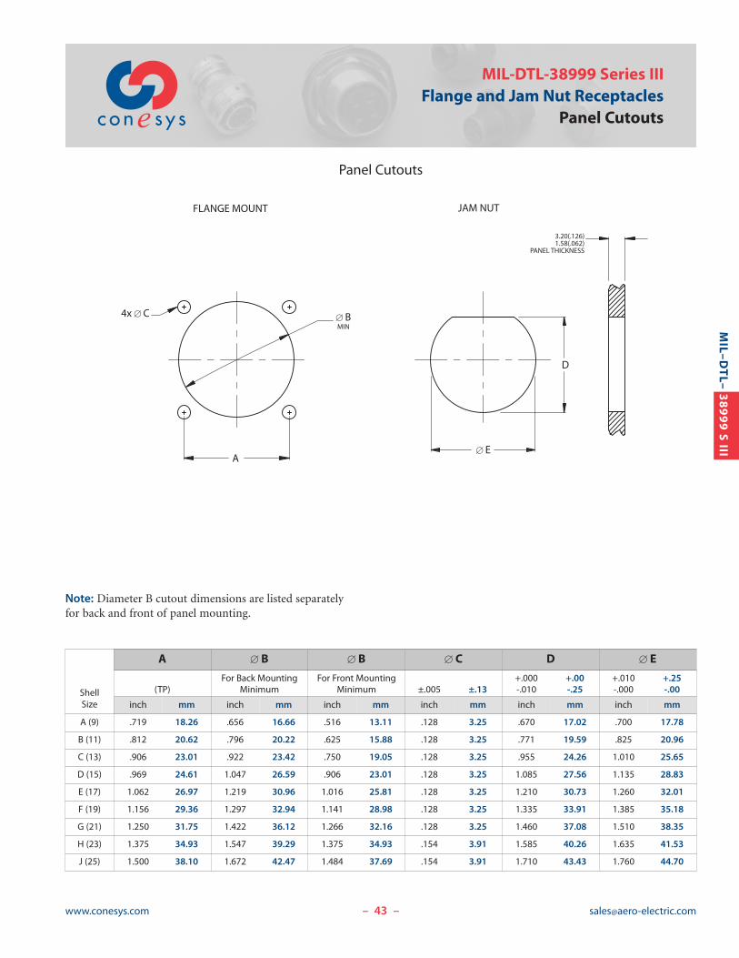
43www.conesys.com [email protected]
MIL–D
TL–
38999 S III
MIL-DTL-38999 Series IIIFlange and Jam Nut Receptacles
Panel Cutouts
Panel Cutouts
– –
Note: Diameter B cutout dimensions are listed separatelyfor back and front of panel mounting.
A[ E
4x [ C [ BMIN
FLANGE MOUNT
3.20(.126)1.58(.062)
PANEL THICKNESS
D
JAM NUT
ShellSize
A � B � B � C D � E
For Back Mounting For Front Mounting +.000 +.00 +.010 +.25(TP) Minimum Minimum ±.005 ±.13 -.010 -.25 -.000 -.00
inch mm inch mm inch mm inch mm inch mm inch mm
A (9) .719 18.26 .656 16.66 .516 13.11 .128 3.25 .670 17.02 .700 17.78
B (11) .812 20.62 .796 20.22 .625 15.88 .128 3.25 .771 19.59 .825 20.96
C (13) .906 23.01 .922 23.42 .750 19.05 .128 3.25 .955 24.26 1.010 25.65
D (15) .969 24.61 1.047 26.59 .906 23.01 .128 3.25 1.085 27.56 1.135 28.83
E (17) 1.062 26.97 1.219 30.96 1.016 25.81 .128 3.25 1.210 30.73 1.260 32.01
F (19) 1.156 29.36 1.297 32.94 1.141 28.98 .128 3.25 1.335 33.91 1.385 35.18
G (21) 1.250 31.75 1.422 36.12 1.266 32.16 .128 3.25 1.460 37.08 1.510 38.35
H (23) 1.375 34.93 1.547 39.29 1.375 34.93 .154 3.91 1.585 40.26 1.635 41.53
J (25) 1.500 38.10 1.672 42.47 1.484 37.69 .154 3.91 1.710 43.43 1.760 44.70

44www.conesys.com [email protected]
MIL–D
TL–
38999 S III
MIL-DTL-38999Contacts, Tools and Seal PlugsSeries III
Contacts, Plastic Insertion/Removal Tools and Seal Plugs
Crimping and Metal Insertion/Extraction Tools
Contact and Wire Data
– –
† MS3348 bushing required with 12 gauge wire.* When tested with silver-plated wire.** Insertion tool is not required.*** Dummy contact, used in lieu of unwired contact and seal plug.**** Daniels Manufacturing part number.
Note: Size 8 coax contacts are used with M17/095-RG180cable, while size 8 Twinax contacts are used with M17/176-00002 cable.
ContactSize
Application Pin Contacts Socket Contacts Seal Plugs Insertion/Removal Tools
Plastic
Type Military No. Military No. Military No. Military No.
22D Power/Signal M39029/58-360 M39029/56-348 MS27488-22-1 M81969/14-01
20 Power/Signal M39029/58-363 M39029/56-351 MS27488-20-1 M81969/14-10
16 Power/Signal M39029/58-364 M39029/56-352 MS27488-16-1 M81969/14-03
12 Power/Signal M39029/58-365 M39029/56-353
MS27488-12-1 M81969/14-0412 Coax Coax M39029/28-211 M39029/75-416
12 Coax Coax M39029/102-558 M39029/103-559
10 (Power) Power M39029/58-528 M39029/56-527 M85049/81-10*** M81969/14-05
8 Coax Coax M39029/60-367 M39029/59-366 MS27488-8-1 M81969/14-06
8 Twinax Twinax M39029/90-529 M39029/91-530 MS27488-8-1 M81969/14-12
Contact Size/Type
Crimp Tool Positioner Positioner Insertion Tool Extraction Tool
For Pin Contacts For Socket Contacts Metal Metal
Military No. Military No. Military No. Military No. Military No.
22D M22520/2-01 M22520/2-09 M22520/2-07 M81969/8-01 M81969/8-02
20M22520/1-01 M22520/1-04 M22520/1-04
M81969/8-05 M81969/8-06M22520/2-01 M22520/2-10 M22520/2-10
16 M22520/1-01 M22520/1-04 M22520/1-04 M81969/8-07 M81969/8-08
12 M22520/1-01 M22520/1-04 M22520/1-04
M81969/8-09 M81969/8-1012 Coax Inner M22520/2-01 M22520/2-34 M22520/2-34
12 Coax Outer M22520/31-01 M22520/31-02 M22520/31-02
10 ( Power) 1716P-1**** N/A N/A M81969/8-11 M81969/8-12
8 Coax Inner M22520/2-01 M22520/2-31 M22520/2-31
M81969/8-13** M81969/8-148 Coax Outer M22520/5-01
M22520/5-05 M22520/5-05
Die Closure B Die Closure B
8 Twinax Center M22520/2-01 M22520/2-37 M22520/2-37
— —8 Twinax Outer & Intermediate
M22520/5-01 M22520/5-200 M22520/5-200
Contact Size
Test Current* Voltage* Crimp Well Data Wire Range Finished Wire � Range
DC Test Max. Drop Well Dia. Minimum Well Dept Minimum Maximum
Amps Millivolts inch inch mm AWG mm2 inch mm inch mm
22D 5.0 73 .0345 ±.0010 .141 3.58 28-22 .08-.33 .030 .76 .054 1.37
20 7.5 55 .047 ±.001 .209 5.31 24-20 .20-.52 .040 1.02 .083 2.11
16 13.0 49 .067 ±.001 .209 5.31 20-16 .52-1.31 .065 1.65 .109 2.77
12 23.0 42 .100 ±.002 .209 5.31 14-12 2.08-3.31 .097 2.46 .142 3.61
10 33.0 33 .137 ±.003 .355 9.02 12-10† 3.31-5.26 .135 3.42 .162 4.12
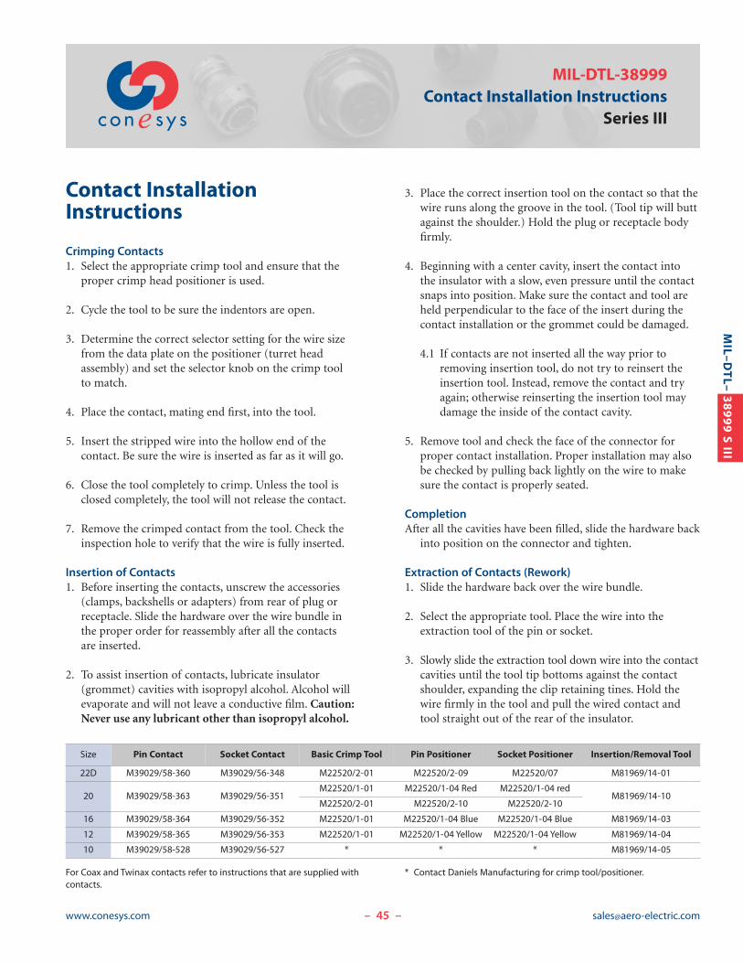
45www.conesys.com [email protected]
MIL–D
TL–
38999 S III
MIL-DTL-38999Contact Installation Instructions
Series III
– –
Contact InstallationInstructions
Crimping Contacts 1. Select the appropriate crimp tool and ensure that the
proper crimp head positioner is used.
2. Cycle the tool to be sure the indentors are open.
3. Determine the correct selector setting for the wire sizefrom the data plate on the positioner (turret head assembly) and set the selector knob on the crimp tool to match.
4. Place the contact, mating end first, into the tool.
5. Insert the stripped wire into the hollow end of the contact. Be sure the wire is inserted as far as it will go.
6. Close the tool completely to crimp. Unless the tool isclosed completely, the tool will not release the contact.
7. Remove the crimped contact from the tool. Check theinspection hole to verify that the wire is fully inserted.
Insertion of Contacts1. Before inserting the contacts, unscrew the accessories
(clamps, backshells or adapters) from rear of plug orreceptacle. Slide the hardware over the wire bundle in the proper order for reassembly after all the contacts are inserted.
2. To assist insertion of contacts, lubricate insulator (grommet) cavities with isopropyl alcohol. Alcohol willevaporate and will not leave a conductive film. Caution:Never use any lubricant other than isopropyl alcohol.
3. Place the correct insertion tool on the contact so that thewire runs along the groove in the tool. (Tool tip will buttagainst the shoulder.) Hold the plug or receptacle bodyfirmly.
4. Beginning with a center cavity, insert the contact into the insulator with a slow, even pressure until the contactsnaps into position. Make sure the contact and tool areheld perpendicular to the face of the insert during thecontact installation or the grommet could be damaged.
4.1 If contacts are not inserted all the way prior toremoving insertion tool, do not try to reinsert theinsertion tool. Instead, remove the contact and tryagain; otherwise reinserting the insertion tool maydamage the inside of the contact cavity.
5. Remove tool and check the face of the connector forproper contact installation. Proper installation may alsobe checked by pulling back lightly on the wire to makesure the contact is properly seated.
CompletionAfter all the cavities have been filled, slide the hardware back
into position on the connector and tighten.
Extraction of Contacts (Rework)1. Slide the hardware back over the wire bundle.
2. Select the appropriate tool. Place the wire into theextraction tool of the pin or socket.
3. Slowly slide the extraction tool down wire into the contactcavities until the tool tip bottoms against the contactshoulder, expanding the clip retaining tines. Hold thewire firmly in the tool and pull the wired contact andtool straight out of the rear of the insulator.
Size Pin Contact Socket Contact Basic Crimp Tool Pin Positioner Socket Positioner Insertion/Removal Tool
22D M39029/58-360 M39029/56-348 M22520/2-01 M22520/2-09 M22520/07 M81969/14-01
20 M39029/58-363 M39029/56-351M22520/1-01 M22520/1-04 Red M22520/1-04 red
M81969/14-10M22520/2-01 M22520/2-10 M22520/2-10
16 M39029/58-364 M39029/56-352 M22520/1-01 M22520/1-04 Blue M22520/1-04 Blue M81969/14-03
12 M39029/58-365 M39029/56-353 M22520/1-01 M22520/1-04 Yellow M22520/1-04 Yellow M81969/14-04
10 M39029/58-528 M39029/56-527 * * * M81969/14-05
For Coax and Twinax contacts refer to instructions that are supplied withcontacts.
* Contact Daniels Manufacturing for crimp tool/positioner.

46www.conesys.com [email protected]
MIL–D
TL–
5015 S III
– –
MIL-DTL-5015Features and ApplicationSeries III (Rear Release)
www.conesys.com [email protected]
Features and Application
The threaded coupling, environmentally sealed MIL-DTL-5015 Series III connector with rear-removablecrimp contacts was developed to replace the earlier soldertype. This redesigned connector is intermateable and intermountable with the MIL-DTL-5015 Series I solder type(MS310*) as well as the MIL-DTL- 83723 Series II (USAF)crimp type and MIL-DTL-5015 Series II Front Release(MS340*). Thus, it provides for a minimum effort and higheconomy upgrade for existing applications.
These connectors are recommended for a wide range ofapplications, from commercial/industrial and mass transportation systems to the most stringent high reliabilitydefense and aerospace requirements.
This family of connectors is offered in four receptacle mounting configurations. They include two square flangereceptacles, both wall and box mounting; cable connectingreceptacles; and jam nut receptacles which incorporate “O”ring seals, designed for rear panel “D” hole mounting.
Two plug styles are offered - standard plug with captivatedcoupling nut retained by a combination “L” washer andretaining ring to prevent inadvertent disassembly and a self-locking, anti-decoupling plug, which eliminates the needfor safety wiring.
Eighty-eight insert arrangements per MIL-STD-1651 are tooledand qualified to MIL-DTL-5015, utilizing 1 to 85 contacts.Contacts come in sizes 16, 12, 8, 4 and 0, terminating wiresizes from 20 gauge to 0 gauge.
These connectors are available in wide range of shell materials and finishes. Aluminum shells are offered in both electroless nickel and olive drab cadmium to both commercial and MS callouts. Other finishes such as anodicand zinc nickel are available upon request to commercial callouts only. In addition, we offer passivated stainless steelshells with both standard and firewall-rated inserts, and carbon steel shells with firewall inserts.
Lockwiring Eliminated – Self-locking plug eliminates theneed for lockwiring.
Universal I/R Tool – A single, expendable plastic tool is usedfor both insertion and removal of contacts.
Insert Polarization – Alternate insert clocking positions aidin mating of adjacent connectors having identical insertarrangement.
Closed-Entry Socket Insert – Hard dielectric socket face haslead-in chamfers for positive alignment of pins (even partiallybent within pre-established limits) with sockets.
Interfacial Pin Insert Seal – Raised moisture barriersaround each pin, which mate into lead-in chamfers of hardface socket insert, provide individual contact sealing.Interfacial seal is never touched by service tools.
Elastomer Wire Sealing Grommet – Sealing over a widerange of wire diameters is assured by a triple wire seal in eachcavity at the rear of the connector.
Superior Contact Stability – Rear release crimp contact system features a stamped beryllium-copper retaining clipcaptivated by molded-in shoulders of each contact cavity inthe insulator. A rear-inserted M81969 plastic tool expands the tines beyond the shoulder, releasing the contact.
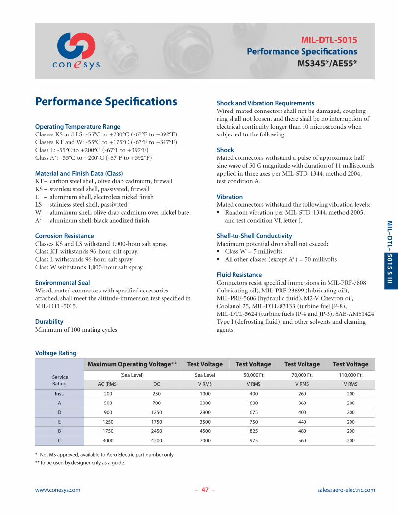
47www.conesys.com [email protected]
MIL–D
TL–
5015 S III
MIL-DTL-5015Performance Specifications
MS345*/AE55*
– –
Performance Specifications
Operating Temperature RangeClasses KS and LS: -55°C to +200°C (-67°F to +392°F)Classes KT and W: -55°C to +175°C (-67°F to +347°F)Class L: -55°C to +200°C (-67°F to +392°F)Class A*: -55°C to +200°C (-67°F to +392°F)
Material and Finish Data (Class)KT– carbon steel shell, olive drab cadmium, firewallKS – stainless steel shell, passivated, firewallL – aluminum shell, electroless nickel finishLS – stainless steel shell, passivatedW – aluminum shell, olive drab cadmium over nickel baseA* – aluminum shell, black anodized finish
Corrosion ResistanceClasses KS and LS withstand 1,000-hour salt spray.Class KT withstands 96-hour salt spray.Class L withstands 96-hour salt spray.Class W withstands 1,000-hour salt spray.
Environmental SealWired, mated connectors with specified accessoriesattached, shall meet the altitude-immersion test specified inMIL-DTL-5015.
DurabilityMinimum of 100 mating cycles
Voltage Rating
Shock and Vibration RequirementsWired, mated connectors shall not be damaged, couplingring shall not loosen, and there shall be no interruption ofelectrical continuity longer than 10 microseconds when subjected to the following:
ShockMated connectors withstand a pulse of approximate halfsine wave of 50 G magnitude with duration of 11 millisecondsapplied in three axes per MIL-STD-1344, method 2004, test condition A.
VibrationMated connectors withstand the following vibration levels:� Random vibration per MIL-STD-1344, method 2005,and test condition VI, letter J.
Shell-to-Shell ConductivityMaximum potential drop shall not exceed:� Class W = 5 millivolts� All other classes (except A*) = 50 millivolts
Fluid ResistanceConnectors resist specified immersions in MIL-PRF-7808(lubricating oil), MIL-PRF-23699 (lubricating oil), MIL-PRF-5606 (hydraulic fluid), M2-V Chevron oil,Coolanol 25, MIL-DTL-83133 (turbine fuel JP-8), MIL-DTL-5624 (turbine fuels JP-4 and JP-5), SAE-AMS1424Type I (defrosting fluid), and other solvents and cleaningagents.
* Not MS approved, available to Aero-Electric part number only.
**To be used by designer only as a guide.
ServiceRating
Maximum Operating Voltage** Test Voltage Test Voltage Test Voltage Test Voltage
(Sea Level) Sea Level 50,000 Ft 70,000 Ft. 110,000 Ft.
AC (RMS) DC V RMS V RMS V RMS V RMS
Inst. 200 250 1000 400 260 200
A 500 700 2000 600 360 200
D 900 1250 2800 675 400 200
E 1250 1750 3500 750 440 200
B 1750 2450 4500 825 480 200
C 3000 4200 7000 975 560 200
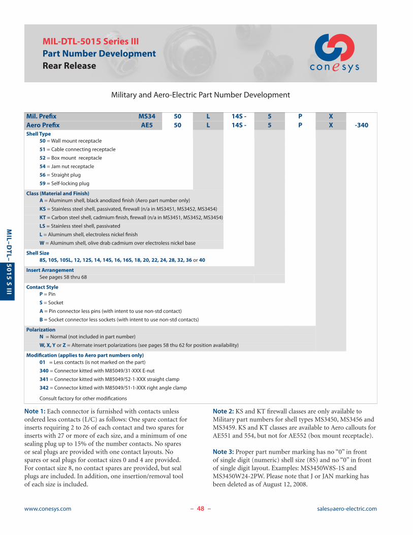
48www.conesys.com [email protected]
MIL–D
TL–
5015 S III
MIL-DTL-5015 Series IIIPart Number DevelopmentRear Release
Military and Aero-Electric Part Number Development
– –
Note 1: Each connector is furnished with contacts unlessordered less contacts (L/C) as follows: One spare contact forinserts requiring 2 to 26 of each contact and two spares forinserts with 27 or more of each size, and a minimum of onesealing plug up to 15% of the number contacts. No sparesor seal plugs are provided with one contact layouts. Nospares or seal plugs for contact sizes 0 and 4 are provided.For contact size 8, no contact spares are provided, but sealplugs are included. In addition, one insertion/removal toolof each size is included.
Note 2: KS and KT firewall classes are only available toMilitary part numbers for shell types MS3450, MS3456 andMS3459. KS and KT classes are available to Aero callouts forAE551 and 554, but not for AE552 (box mount receptacle).
Note 3: Proper part number marking has no “0” in front of single digit (numeric) shell size (8S) and no “0” in frontof single digit layout. Examples: MS3450W8S-1S and MS3450W24-2PW. Please note that J or JAN marking hasbeen deleted as of August 12, 2008.
Mil. Prefix MS34 50 L 14S - 5 P XAero Prefix AE5 50 L 14S - 5 P X -340Shell Type
50 = Wall mount receptacle
51 = Cable connecting receptacle
52 = Box mount receptacle
54 = Jam nut receptacle
56 = Straight plug
59 = Self-locking plug
Class (Material and Finish)A = Aluminum shell, black anodized finish (Aero part number only)
KS = Stainless steel shell, passivated, firewall (n/a in MS3451, MS3452, MS3454)
KT = Carbon steel shell, cadmium finish, firewall (n/a in MS3451, MS3452, MS3454)
LS = Stainless steel shell, passivated
L = Aluminum shell, electroless nickel finish
W = Aluminum shell, olive drab cadmium over electroless nickel base
Shell Size8S, 10S, 10SL, 12, 12S, 14, 14S, 16, 16S, 18, 20, 22, 24, 28, 32, 36 or 40
Insert ArrangementSee pages 58 thru 68
Contact StyleP = Pin
S = Socket
A = Pin connector less pins (with intent to use non-std contact)
B = Socket connector less sockets (with intent to use non-std contacts)
PolarizationN = Normal (not included in part number)
W, X, Y or Z = Alternate insert polarizations (see pages 58 thu 62 for position availability)
Modification (applies to Aero part numbers only)01 = Less contacts (is not marked on the part)
340 = Connector kitted with M85049/31-XXX E-nut
341 = Connector kitted with M85049/52-1-XXX straight clamp
342 = Connector kitted with M85049/51-1-XXX right angle clamp
Consult factory for other modifications
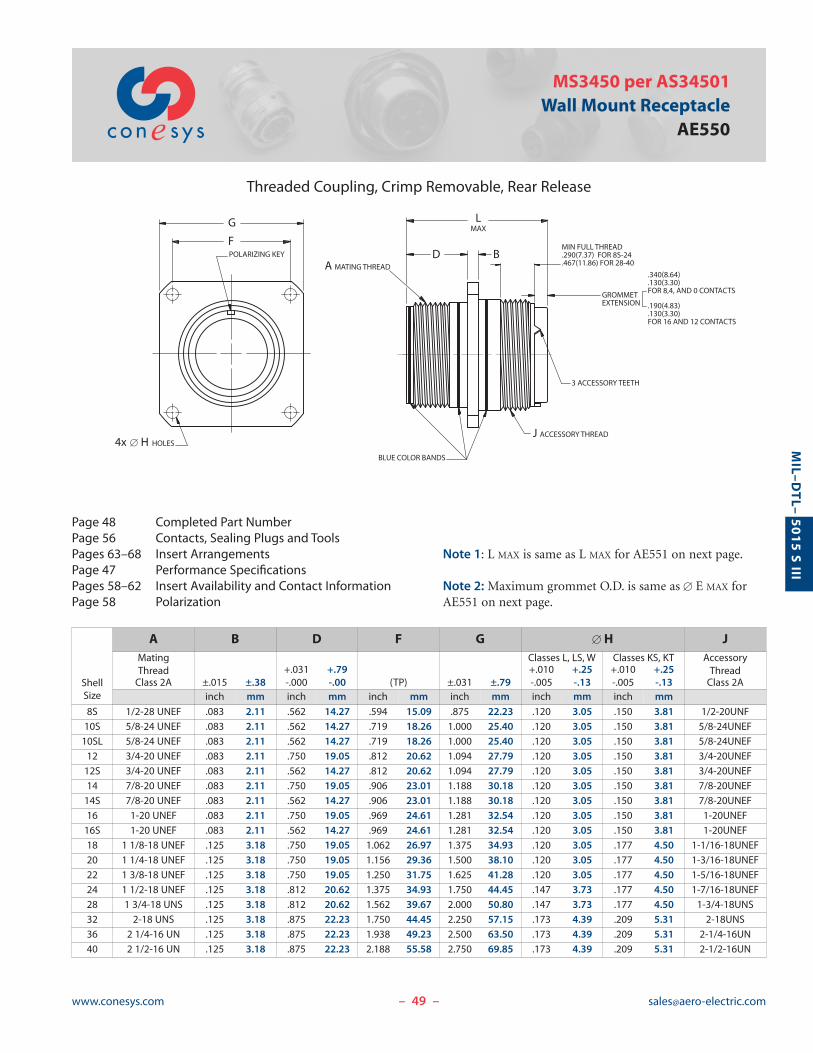
49www.conesys.com [email protected]
MIL–D
TL–
5015 S III
MS3450 per AS34501Wall Mount Receptacle
AE550
Threaded Coupling, Crimp Removable, Rear Release
– –
Note 1: L MAX is same as L MAX for AE551 on next page.
Note 2:Maximum grommet O.D. is same as � E MAX forAE551 on next page.
BLUE COLOR BANDS
J ACCESSORY THREAD
G
F
A MATING THREADD BPOLARIZING KEY
4x [ H HOLES
3 ACCESSORY TEETH
LMAX
MIN FULL THREAD.290(7.37) FOR 8S-24.467(11.86) FOR 28-40
GROMMETEXTENSION .190(4.83)
.130(3.30)FOR 16 AND 12 CONTACTS
.340(8.64)
.130(3.30)FOR 8,4, AND 0 CONTACTS
Page 48 Completed Part NumberPage 56 Contacts, Sealing Plugs and ToolsPages 63–68 Insert ArrangementsPage 47 Performance SpecificationsPages 58–62 Insert Availability and Contact InformationPage 58 Polarization
ShellSize
A B D F G � H J Mating Classes L, LS, W Classes KS, KT AccessoryThread +.031 +.79 +.010 +.25 +.010 +.25 ThreadClass 2A ±.015 ±.38 -.000 -.00 (TP) ±.031 ±.79 -.005 -.13 -.005 -.13 Class 2A
inch mm inch mm inch mm inch mm inch mm inch mm8S 1/2-28 UNEF .083 2.11 .562 14.27 .594 15.09 .875 22.23 .120 3.05 .150 3.81 1/2-20UNF10S 5/8-24 UNEF .083 2.11 .562 14.27 .719 18.26 1.000 25.40 .120 3.05 .150 3.81 5/8-24UNEF10SL 5/8-24 UNEF .083 2.11 .562 14.27 .719 18.26 1.000 25.40 .120 3.05 .150 3.81 5/8-24UNEF12 3/4-20 UNEF .083 2.11 .750 19.05 .812 20.62 1.094 27.79 .120 3.05 .150 3.81 3/4-20UNEF12S 3/4-20 UNEF .083 2.11 .562 14.27 .812 20.62 1.094 27.79 .120 3.05 .150 3.81 3/4-20UNEF14 7/8-20 UNEF .083 2.11 .750 19.05 .906 23.01 1.188 30.18 .120 3.05 .150 3.81 7/8-20UNEF14S 7/8-20 UNEF .083 2.11 .562 14.27 .906 23.01 1.188 30.18 .120 3.05 .150 3.81 7/8-20UNEF16 1-20 UNEF .083 2.11 .750 19.05 .969 24.61 1.281 32.54 .120 3.05 .150 3.81 1-20UNEF16S 1-20 UNEF .083 2.11 .562 14.27 .969 24.61 1.281 32.54 .120 3.05 .150 3.81 1-20UNEF18 1 1/8-18 UNEF .125 3.18 .750 19.05 1.062 26.97 1.375 34.93 .120 3.05 .177 4.50 1-1/16-18UNEF20 1 1/4-18 UNEF .125 3.18 .750 19.05 1.156 29.36 1.500 38.10 .120 3.05 .177 4.50 1-3/16-18UNEF22 1 3/8-18 UNEF .125 3.18 .750 19.05 1.250 31.75 1.625 41.28 .120 3.05 .177 4.50 1-5/16-18UNEF24 1 1/2-18 UNEF .125 3.18 .812 20.62 1.375 34.93 1.750 44.45 .147 3.73 .177 4.50 1-7/16-18UNEF28 1 3/4-18 UNS .125 3.18 .812 20.62 1.562 39.67 2.000 50.80 .147 3.73 .177 4.50 1-3/4-18UNS32 2-18 UNS .125 3.18 .875 22.23 1.750 44.45 2.250 57.15 .173 4.39 .209 5.31 2-18UNS36 2 1/4-16 UN .125 3.18 .875 22.23 1.938 49.23 2.500 63.50 .173 4.39 .209 5.31 2-1/4-16UN40 2 1/2-16 UN .125 3.18 .875 22.23 2.188 55.58 2.750 69.85 .173 4.39 .209 5.31 2-1/2-16UN

50www.conesys.com [email protected]
MIL–D
TL–
5015 S III
MS3451 per AS34511Cable Connecting ReceptacleAE551
Threaded Coupling, Crimp Removable, Rear Release
– –
[ S [ EMAX
GROMMET
BLUE COLOR BANDS V ACCESSORY THREAD
A MATING THREAD
M
L MAXR
ACROSS FLATS
3 ACCESSORY TEETH
MIN FULL THREAD.290(7.37) FOR 8S-24.467(11.86) FOR 28-40
.083±.015(2.11±.38) FOR 8S-16S
.125±.015(3.18±.38) FOR 18-40
GROMMETEXTENSION .190(4.83)
.130(3.30)FOR 16 AND 12 CONTACTS
.340(8.64)
.130(3.30)FOR 8,4, AND 0 CONTACTS
POLARIZING KEY
ShellSize
A � E L MAX M R � S V
Mating Thread 16 & 12 8, 4 & 0 +.031 +.79 Accessory ThreadClass 2A Maximum Contacts Contacts -.000 -.00 ±.031 ±.79 Class 2A
inch mm inch mm inch mm inch mm inch mm inch mm
8S 1/2-28 UNEF .305 7.75 2.031 51.59 – – .562 14.27 .504/.496 12.80/12.60 .729 18.52 1/2-20UNF
10S 5/8-24 UNEF .405 10.29 2.031 51.59 – – .562 14.27 .629/.621 15.98/15.77 .854 21.69 5/8-24UNEF
10SL 5/8-24 UNEF .405 10.29 2.031 51.59 – – .562 14.27 .629/.621 15.98/15.77 .854 21.69 5/8-24UNEF
12 3/4-20 UNEF .549 13.94 2.125 53.98 – – .750 19.05 .754/.746 19.15/18.95 .974 24.74 3/4-20UNEF
12S 3/4-20 UNEF .549 13.94 2.031 51.59 – – .562 14.27 .754/.746 19.15/18.95 .974 24.74 3/4-20UNEF
14 7/8-20 UNEF .665 16.89 2.125 53.98 – – .750 19.05 .879/.871 22.33/22.12 1.099 27.91 7/8-20UNEF
14S 7/8-20 UNEF .665 16.89 2.031 51.59 – – .562 14.27 .879/.871 22.33/22.12 1.099 27.91 7/8-20UNEF
16 1-20 UNEF .790 20.07 2.125 53.98 2.500 63.50 .750 19.05 1.005/.996 25.53/25.30 1.224 31.09 1-20UNEF
16S 1-20 UNEF .790 20.07 2.031 51.59 – – .562 14.27 1.005/.996 25.53/25.30 1.224 31.09 1-20UNEF
18 1 1/8-18 UNEF .869 22.07 2.125 53.98 2.500 63.50 .750 19.05 1.131/1.121 28.73/28.47 1.349 34.26 1-1/16-18UNEF
20 1 1/4-18 UNEF .994 25.25 2.125 53.98 2.500 63.50 .750 19.05 1.256/1.246 31.90/31.65 1.474 37.44 1-3/16-18UNEF
22 1 3/8-18 UNEF 1.119 28.42 2.125 53.98 2.500 63.50 .750 19.05 1.381/1.371 35.08/34.82 1.599 40.61 1-5/16-18UNEF
24 1 1/2-18 UNEF 1.244 31.60 2.125 53.98 2.500 63.50 .812 20.62 1.506/1.496 38.25/38.00 1.715 43.56 1-7/16 -18UNEF
28 1 3/4-18 UNS 1.465 37.21 2.125 53.98 2.500 63.50 .812 20.62 1.756/1.746 44.60/44.35 1.974 50.14 1-3/4-18UNS
32 2-18 UNS 1.715 43.56 2.125 53.98 2.500 63.50 .875 22.23 2.007/1.996 50.98/50.70 2.224 56.49 2-18UNS
36 2 1/4-16 UN 1.930 49.02 2.125 53.98 2.500 63.50 .875 22.23 2.257/2.246 57.33/57.05 2.474 62.84 2-1/4-16UN
40 2 1/2-16 UN 2.145 54.48 2.125 53.98 2.500 63.50 .875 22.23 2.511/2.496 63.78/63.40 2.724 69.19 2-1/2-16UN
Page 48 Completed Part NumberPage 56 Contacts, Sealing Plugs and ToolsPages 63–68 Insert ArrangementsPage 47 Performance SpecificationsPages 58–62 Insert Availability and Contact InformationPage 58 Polarization

51www.conesys.com [email protected]
MIL–D
TL–
5015 S III
MS3452Box Mount Receptacle
AE552
Threaded Coupling, Crimp Removable, Rear Release
– –
S
R
A MATING THREADM
LMAX
[ GG
4x [ T HOLES
.083±.015(2.11±.38) FOR 8S-16S
.125±.015(3.18±.38) FOR 18-40
BLUE COLOR BAND
POLARIZING KEY
Page 48 Completed Part NumberPage 56 Contacts, Sealing Plugs and ToolsPages 63–68 Insert ArrangementsPage 47 Performance SpecificationsPages 58–62 Insert Availability and Contact InformationPage 58 Polarization
Note 1: The insulation material shall be above, flush with,or no more than .015 inches (.38 mm) below the metal shell.
Note 2: At time of catalog printing, MS3452 was not superseded by SAE document - AS34521.
ShellSize
A � GG L MAX M R S � T
Mating Thread 16 & 12 8, 4 & 0 +.031 +.79 +.010 +.25Class 2A ±.016 ±.41 Contacts Contacts -.000 -.00 (TP) ±.031 ±.79 -.005 -.13
inch mm inch mm inch mm inch mm inch mm inch mm inch mm
8S 1/2-28 UNEF .500 12.70 1.662 42.21 – – .562 14.27 .594 15.09 .875 22.23 .120 3.05
10S 5/8-24 UNEF .625 15.88 1.662 42.21 – – .562 14.27 .719 18.26 1.000 25.40 .120 3.05
10SL 5/8-24 UNEF .625 15.88 1.662 42.21 – – .562 14.27 .719 18.26 1.000 25.40 .120 3.05
12 3/4-20 UNEF .750 19.05 1.662 42.21 – – .750 19.05 .812 20.62 1.094 27.79 .120 3.05
12S 3/4-20 UNEF .750 19.05 1.662 42.21 – – .562 14.27 .812 20.62 1.094 27.79 .120 3.05
14 7/8-20 UNEF .875 22.23 1.662 42.21 – – .750 19.05 .906 23.01 1.188 30.18 .120 3.05
14S 7/8-20 UNEF .875 22.23 1.662 42.21 – – .562 14.27 .906 23.01 1.188 30.18 .120 3.05
16 1-20 UNEF 1.000 25.40 1.662 42.21 1.937 49.20 .750 19.05 .969 24.61 1.281 32.54 .120 3.05
16S 1-20 UNEF 1.000 25.40 1.662 42.21 – – .562 14.27 .969 24.61 1.281 32.54 .120 3.05
18 1 1/8-18 UNEF 1.062 26.97 1.662 42.21 1.937 49.20 .750 19.05 1.062 26.97 1.375 34.93 .120 3.05
20 1 1/4-18 UNEF 1.187 30.15 1.662 42.21 1.937 49.20 .750 19.05 1.156 29.36 1.500 38.10 .120 3.05
22 1 3/8-18 UNEF 1.312 33.32 1.662 42.21 1.937 49.20 .750 19.05 1.250 31.75 1.625 41.28 .120 3.05
24 1 1/2-18 UNEF 1.437 36.50 1.662 42.21 1.937 49.20 .812 20.62 1.375 34.93 1.750 44.45 .147 3.73
28 1 3/4-18 UNS 1.750 44.45 1.662 42.21 1.937 49.20 .812 20.62 1.562 39.67 2.000 50.80 .147 3.73
32 2-18 UNS 2.000 50.80 1.662 42.21 1.937 49.20 .875 22.23 1.750 44.45 2.250 57.15 .173 4.39
36 2 1/4-16 UN 2.250 57.15 1.662 42.21 1.937 49.20 .875 22.23 1.938 49.23 2.500 63.50 .173 4.39
40 2 1/2-16 UN 2.500 63.50 1.662 42.21 1.937 49.20 .875 22.23 2.188 55.58 2.750 69.85 .173 4.39

52www.conesys.com [email protected]
MIL–D
TL–
5015 S III
MS3454 per AS34541Jam Nut ReceptacleAE554
Threaded Coupling, Crimp Removable, Rear Release
– –
MIN FULL THREAD.290(7.37) FOR 8S-24.467(11.86) FOR 28-40
BLUE COLOR BAND
BLUE COLOR BAND
D .180(4.57).165(4.19)
FMATING THREAD
HACCESSORY THREAD
[ .032(.81) MAXSAFETY WIRE HOLE(3 EQALLY SPACED)
"O" RING
A
B
[ C
SPRING PIN MS171430
PANEL THICKNESS.128(3.25) MAX
.196(4.98)
.186(4.72)
EMAX
3 ACCESSORY TEETH
GROMMETEXTENSION .190(4.83)
.130(3.30)FOR 16 AND 12 CONTACTS
.340(8.64)
.130(3.30)FOR 8,4, AND 0 CONTACTS
POLARIZING KEY
Page 48 Completed Part NumberPage 56 Contacts, Sealing Plugs and ToolsPages 63–68 Insert ArrangementsPage 47 Performance SpecificationsPages 58–62 Insert Availability and Contact InformationPage 58 Polarization
Note:Maximum grommet O.D. is same as � E MAX on nextpage.
ShellSize
A B � C D E MAX F H
16 & 12 8, 4 & 0 Mating Thread Accessory Thread±.005 ±.13 ±.010 ±.25 ±.005 ±.13 ±.005 ±.13 Contacts Contacts Class 2A Class 2A
inch mm inch mm inch mm inch mm inch mm inch mm
8S 1.187 30.15 .687 17.45 1.272 32.31 .720 18.29 2.031 51.59 – – 1/2-28 UNEF 1/2-20UNF
10S 1.312 33.32 .812 20.62 1.397 35.48 .720 18.29 2.031 51.59 – – 5/8-24 UNEF 5/8-24UNEF
10SL 1.312 33.32 .812 20.62 1.397 35.48 .720 18.29 2.031 51.59 – – 5/8-24 UNEF 5/8-24UNEF
12 1.437 36.50 .937 23.80 1.522 38.66 .970 24.64 2.125 53.98 – – 3/4-20 UNEF 3/4-20UNEF
12S 1.437 36.50 .937 23.80 1.522 38.66 .720 18.29 2.031 51.59 – – 3/4-20 UNEF 3/4-20UNEF
14 1.562 39.67 1.125 28.58 1.647 41.83 .970 24.64 2.125 53.98 – – 7/8-20 UNEF 7/8-20UNEF
14S 1.562 39.67 1.125 28.58 1.647 41.83 .720 18.29 2.031 51.59 – – 7/8-20 UNEF 7/8-20UNEF
16 1.687 42.85 1.250 31.75 1.772 45.01 .970 24.64 2.125 53.98 2.500 63.50 1-20 UNEF 1-20UNEF
16S 1.687 42.85 1.250 31.75 1.772 45.01 .720 18.29 2.031 51.59 – – 1-20 UNEF 1-20UNEF
18 1.812 46.02 1.375 34.93 1.897 48.18 .970 24.64 2.125 53.98 2.500 63.50 1 1/8-18 UNEF 1-1/16-18UNEF
20 1.937 49.20 1.500 38.10 2.022 51.36 .970 24.64 2.125 53.98 2.500 63.50 1 1/4-18 UNEF 1-3/16-18UNEF
22 2.156 54.76 1.625 41.28 2.241 56.92 .970 24.64 2.125 53.98 2.500 63.50 1 3/8-18 UNEF 1-5/16-18UNEF
24 2.281 57.94 1.750 44.45 2.366 60.10 .970 24.64 2.125 53.98 2.500 63.50 1 1/2-18 UNEF 1-7/16-18UNEF
28 2.531 64.29 2.000 50.80 2.616 66.45 .970 24.64 2.125 53.98 2.500 63.50 1 3/4-18 UNS 1-3/4-18UNS
32 2.781 70.64 2.375 60.33 2.866 72.80 .970 24.64 2.125 53.98 2.500 63.50 2-18 UNS 2-18UNS
36 3.031 76.99 2.625 66.68 3.116 79.15 .970 24.64 2.125 53.98 2.500 63.50 2 1/4-16 UN 2-1/4-16UN
40 3.281 83.34 2.875 73.03 3.366 85.50 .970 24.64 2.125 53.98 2.500 63.50 2 1/2-16 UN 2-1/2-16UN

53www.conesys.com [email protected]
MIL–D
TL–
5015 S III
MS3456Straight Plug
AE556
Threaded Coupling, Crimp Removable, Rear Release
– –
Page 48 Completed Part NumberPage 56 Contacts, Sealing Plugs and ToolsPages 63–68 Insert ArrangementsPage 47 Performance SpecificationsPages 58–62 Insert Availability and Contact InformationPage 58 Polarization
MIN FULL THREAD.290(7.37) FOR 8S-24.467(11.86) FOR 28-40
GROMMETEXTENSION .190(4.83)
.130(3.30)FOR 16 AND 12 CONTACTS
.340(8.64)
.130(3.30)FOR 8,4, AND 0 CONTACTS
[ AMAX
C MATING THREAD
BLUE COLOR BAND
H MAX
3x [ .035(.89) SAFETY WIRE HOLES EQUALLY SPACED (EXCEPT SHELL SIZES 8 TO 14 – 2 HOLES MIN)
F ACCESSORY THREAD
3 TEETHEQUALLY SPACED
[ EMAXGROMMET
[ B
POLARIZING KEYWAY
ShellSize
� A � B C � E F H MAX
Mating Thread Accessory Thread 16 & 12 8, 4 & 0Maximum ±.005 ±.13 Class 2B Maximum Class 2A Contacts Contacts
inch mm inch mm inch mm inch mm inch mm
8S .844 21.44 .360 9.14 1/2-28 UNEF .305 7.75 1/2-20UNF 2.031 51.59 – –
10S .969 24.61 .435 11.05 5/8-24 UNEF .405 10.29 5/8-24UNEF 2.031 51.59 – –
10SL .969 24.61 .443* 11.25* 5/8-24 UNEF .405 10.29 5/8-24UNEF 2.031 51.59 – –
12 1.062 26.97 .550 13.97 3/4-20 UNEF .549 13.94 3/4-20UNEF 2.125 53.98 – –
12S 1.062 26.97 .550 13.97 3/4-20 UNEF .549 13.94 3/4-20UNEF 2.031 51.59 – –
14 1.156 29.36 .670 17.02 7/8-20 UNEF .665 16.89 7/8-20UNEF 2.125 53.98 – –
14S 1.156 29.36 .670 17.02 7/8-20 UNEF .665 16.89 7/8-20UNEF 2.031 51.59 – –
16 1.250 31.75 .800 20.32 1-20 UNEF .790 20.07 1-20UNEF 2.125 53.98 2.500 63.50
16S 1.250 31.75 .800 20.32 1-20 UNEF .790 20.07 1-20UNEF 2.031 51.59 – –
18 1.344 34.14 .925 23.50 1 1/8-18 UNEF .869 22.07 1-1/16-18UNEF 2.125 53.98 2.500 63.50
20 1.469 37.31 1.045 26.54 1 1/4-18 UNEF .994 25.25 1-3/16-18UNEF 2.125 53.98 2.500 63.50
22 1.594 40.49 1.170 29.72 1 3/8-18 UNEF 1.119 28.42 1-5/16-18UNEF 2.125 53.98 2.500 63.50
24 1.719 43.66 1.295 32.89 1 1/2-18 UNEF 1.244 31.60 1-7/16-18UNEF 2.125 53.98 2.500 63.50
28 1.969 50.01 1.515 38.48 1 3/4-18 UNS 1.465 37.21 1-3/4-18UNS 2.125 53.98 2.500 63.50
32 2.219 56.36 1.765 44.83 2-18 UNS 1.715 43.56 2-18UNS 2.125 53.98 2.500 63.50
36 2.469 62.71 1.975 50.17 2 1/4-16 UN 1.930 49.02 2-1/4-16UN 2.125 53.98 2.500 63.50
40 2.719 69.06 2.225 56.52 2 1/2-16 UN 2.145 54.48 2-1/2-16UN 2.125 53.98 2.500 63.50
* Tolerance for this dimension is ± .003(.08)
Note: At time of catalog printing, MS3456 was not superseded by SAE document - AS34561.
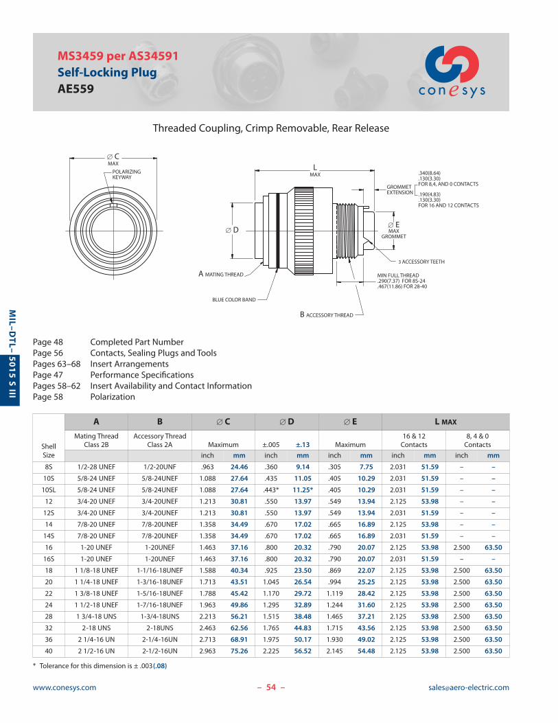
54www.conesys.com [email protected]
MIL–D
TL–
5015 S III
MS3459 per AS34591Self-Locking PlugAE559
Threaded Coupling, Crimp Removable, Rear Release
– –
Page 48 Completed Part NumberPage 56 Contacts, Sealing Plugs and ToolsPages 63–68 Insert ArrangementsPage 47 Performance SpecificationsPages 58–62 Insert Availability and Contact InformationPage 58 Polarization
LMAX
[ CMAX
B ACCESSORY THREAD
3 ACCESSORY TEETH
BLUE COLOR BAND
MIN FULL THREAD.290(7.37) FOR 8S-24.467(11.86) FOR 28-40
[ D[ EMAX
GROMMET
GROMMETEXTENSION .190(4.83)
.130(3.30)FOR 16 AND 12 CONTACTS
.340(8.64)
.130(3.30)FOR 8,4, AND 0 CONTACTS
A MATING THREAD
POLARIZING KEYWAY
ShellSize
A B � C � D � E L MAX
Mating Thread Accessory Thread 16 & 12 8, 4 & 0Class 2B Class 2A Maximum ±.005 ±.13 Maximum Contacts Contacts
inch mm inch mm inch mm inch mm inch mm
8S 1/2-28 UNEF 1/2-20UNF .963 24.46 .360 9.14 .305 7.75 2.031 51.59 – –
10S 5/8-24 UNEF 5/8-24UNEF 1.088 27.64 .435 11.05 .405 10.29 2.031 51.59 – –
10SL 5/8-24 UNEF 5/8-24UNEF 1.088 27.64 .443* 11.25* .405 10.29 2.031 51.59 – –
12 3/4-20 UNEF 3/4-20UNEF 1.213 30.81 .550 13.97 .549 13.94 2.125 53.98 – –
12S 3/4-20 UNEF 3/4-20UNEF 1.213 30.81 .550 13.97 .549 13.94 2.031 51.59 – –
14 7/8-20 UNEF 7/8-20UNEF 1.358 34.49 .670 17.02 .665 16.89 2.125 53.98 – –
14S 7/8-20 UNEF 7/8-20UNEF 1.358 34.49 .670 17.02 .665 16.89 2.031 51.59 – –
16 1-20 UNEF 1-20UNEF 1.463 37.16 .800 20.32 .790 20.07 2.125 53.98 2.500 63.50
16S 1-20 UNEF 1-20UNEF 1.463 37.16 .800 20.32 .790 20.07 2.031 51.59 – –
18 1 1/8-18 UNEF 1-1/16-18UNEF 1.588 40.34 .925 23.50 .869 22.07 2.125 53.98 2.500 63.50
20 1 1/4-18 UNEF 1-3/16-18UNEF 1.713 43.51 1.045 26.54 .994 25.25 2.125 53.98 2.500 63.50
22 1 3/8-18 UNEF 1-5/16-18UNEF 1.788 45.42 1.170 29.72 1.119 28.42 2.125 53.98 2.500 63.50
24 1 1/2-18 UNEF 1-7/16-18UNEF 1.963 49.86 1.295 32.89 1.244 31.60 2.125 53.98 2.500 63.50
28 1 3/4-18 UNS 1-3/4-18UNS 2.213 56.21 1.515 38.48 1.465 37.21 2.125 53.98 2.500 63.50
32 2-18 UNS 2-18UNS 2.463 62.56 1.765 44.83 1.715 43.56 2.125 53.98 2.500 63.50
36 2 1/4-16 UN 2-1/4-16UN 2.713 68.91 1.975 50.17 1.930 49.02 2.125 53.98 2.500 63.50
40 2 1/2-16 UN 2-1/2-16UN 2.963 75.26 2.225 56.52 2.145 54.48 2.125 53.98 2.500 63.50
* Tolerance for this dimension is ± .003(.08)

55www.conesys.com [email protected]
MIL–D
TL–
5015 S III
MIL-DTL-5015 Series III, Rear ReleaseFlange and Jam Nut Receptacles
Panel Cutouts
Panel Cutouts
– –
A
[ C [ BE
[ D
.100(2.54) DIA.
.095(2.41)
MS3454 (AE554) CUTOUT
Flange and Jam Nut Mounting Dimensions
ShellSize
A � B � C � D E
Classes L, LS, W Classes KS, KT+.010 +.25 +.010 +.25 +.015 +.38
(TP) ±.010 ±.25 -.005 -.13 -.005 -.13 -.000 -.00 ±.005 ±.13
inch mm inch mm inch mm inch mm inch mm inch mm
8S .594 15.09 .562 14.27 .120 3.05 .150 3.81 .505 12.83 .323 8.20
10S, 10SL .719 18.26 .688 17.48 .120 3.05 .150 3.81 .630 16.00 .385 9.78
12, 12S .812 20.62 .812 20.62 .120 3.05 .150 3.81 .755 19.18 .448 11.38
14, 14S .906 23.01 .938 23.83 .120 3.05 .150 3.81 .880 22.35 .510 12.95
16, 16S .969 24.61 1.062 26.97 .120 3.05 .150 3.81 1.005 25.53 .573 14.55
18 1.062 26.97 1.188 30.18 .120 3.05 .177 4.50 1.130 28.70 .635 16.13
20 1.156 29.36 1.312 33.32 .120 3.05 .177 4.50 1.255 31.88 .698 17.73
22 1.250 31.75 1.438 36.53 .120 3.05 .177 4.50 1.380 35.05 .760 19.30
24 1.375 34.93 1.562 39.67 .147 3.73 .177 4.50 1.505 38.23 .823 20.90
28 1.562 39.67 1.812 46.02 .147 3.73 .177 4.50 1.755 44.58 .948 24.08
32 1.750 44.45 2.062 52.37 .173 4.39 .209 5.31 2.005 50.93 1.073 27.25
36 1.938 49.23 2.312 58.72 .173 4.39 .209 5.31 2.255 57.28 1.198 30.43
40 2.188 55.58 2.562 65.07 .173 4.39 .209 5.31 2.505 63.63 1.323 33.60

56www.conesys.com [email protected]
MIL–D
TL–
5015 S III
MIL-DTL-5015Contacts, Tools and Seal PlugsMS345*/AE55*
Contacts, Plastic Insertion/Removal Tools and Seal Plugs
Crimping and Metal Insertion/Extraction Tools
Contact and Wire Data
– –
† MS3348 bushings required in crimp barrel to accommodate 10, 6 and2 wire gauges. Bushings are ordered separately.
Note 1: 16S socket contacts are only used in shell sizes 8S,10S, 10SL, 12S, 14S and 16S.
Note 2: Test Current and Maximum Voltage Drop whentested with silver-plated wire at 25°C.
* No spare size 0, 4 and 8 contacts are provided in connector contact packages.** Not supplied as part of connector contact packages.
Note 3: Metal Insertion tool is not req’d for size 8, 4 and 0 contacts. Metal insertion tool for size 16 contacts =M81969/8-207. Metal insertion tool for size 12 contacts =M81969/8-209.
ContactSize
Application Pin Contacts Socket Contacts Seal Plugs Insertion/Removal Tools
Plastic
Type Military No. Military No. Military No. Military No.
16S Power/Signal N/A M39029/30-217MS27488-16-1 M81969/14-03
16 Power/Signal M39029/29-212 M39029/30-218
12 Power/Signal M39029/29-213 M39029/30-219 MS27488-12-1 M81969/14-04
8 Power M39029/29-214* M39029/30-220* MS27488-8-1 M81969/14-06
4 Power M39029/29-215* M39029/30-221* MS27488-4-1** M81969/14-07
0 Power M39029/29-216* M39029/30-222* MS27488-0-1** M81969/14-08
ContactSize
Crimp Tool Positioner Die Set Locator Extraction Tool
Pin & Socket Contacts Pin & Socket Contacts Pin & Socket Contacts Metal
Military No. Military No. Military No. Military No. Military No.
16/16S M22520/1-01 M22520/1-02 N/A N/A M81969/8-208
12 M22520/1-01 M22520/1-02 N/A N/A M81969/8-210
8 M22520/23-01 N/A M22520/23-02 M22520/23-09 M81969/15-01
4 M22520/23-01 N/A M22520/23-03 M22520/23-11 M81969/15-02
0 M22520/23-01 N/A M22520/23-04 M22520/23-13 M81969/15-03
ContactSize
Test Current Voltage Crimp Well Data Wire Range Finished Wire � Range
DC Test Max. Drop Well Dia. Minimum Well Dept Minimum Maximum
Amps Millivolts inch inch mm AWG mm2 inch mm inch mm
16/16S 13 49 .067 ±.001 .250 6.35 20-16 0.52-1.31 .053 1.35 .103 2.62
12 23 42 .100 ±.002 .250 6.35 14-12 2.08-3.31 .085 2.16 .158 4.01
8 46 26 .181 ±.002 .485 12.32 10-8† 5.26-8.37 .132 3.35 .255 6.48
4 80 23 .281 ±.002 .485 12.32 6-4† 13.30-21.15 .237 6.02 .370 9.40
0 150 21 .453 ±.002 .580 14.73 2-0† 33.63-53.48 .360 9.14 .550 13.97

57www.conesys.com [email protected]
MIL–D
TL–
5015 S III
MIL-DTL-5015Contact Installation Instructions
MS345*/AE55*
– –
Contact InstallationInstructions
Crimping Contacts 1. Select the appropriate crimp tool and ensure that the
proper crimp head positioner is used.
2. Cycle the tool to be sure the indentors are open.
3. Determine the correct selector setting for the wire sizefrom the data plate on the positioner (turret head assembly) and set the selector knob on the crimp tool to match.
4. Place the contact, mating end first, into the tool.
5. Insert the stripped wire into the hollow end of the contact. Be sure the wire is inserted as far as it will go.
6. Close the tool completely to crimp. Unless the tool isclosed completely, the tool will not release the contact.
7. Remove the crimped contact from the tool. Check theinspection hole to verify that the wire is fully inserted.
Insertion of Contacts1. Before inserting the contacts, unscrew the accessories
(clamps, backshells or adapters) from rear of plug orreceptacle. Slide the hardware over the wire bundle in the proper order for reassembly after all the contacts are inserted.
2. To assist insertion of contacts, lubricate insulator (grommet) cavities with isopropyl alcohol. Alcohol willevaporate and will not leave a conductive film. Caution:Never use any lubricant other than isopropyl alcohol.
3. Place the correct insertion tool on the contact so that thewire runs along the groove in the tool. (Tool tip will buttagainst the shoulder.) Hold the plug or receptacle bodyfirmly.
4. Beginning with a center cavity, insert the contact into the insulator with a slow, even pressure until the contactsnaps into position. Make sure the contact and tool areheld perpendicular to the face of the insert during thecontact installation or the grommet could be damaged.
4.1 If contacts are not inserted all the way prior toremoving insertion tool, do not try to reinsert theinsertion tool. Instead, remove the contact and tryagain; otherwise reinserting the insertion tool maydamage the inside of the contact cavity.
5. Remove tool and check the face of the connector forproper contact installation. Proper installation may alsobe checked by pulling back lightly on the wire to makesure the contact is properly seated.
CompletionAfter all the cavities have been filled, slide the hardware back
into position on the connector and tighten.
Extraction of Contacts (Rework)1. Slide the hardware back over the wire bundle.
2. Select the appropriate tool. Place the wire into theextraction tool of the pin or socket.
3. Slowly slide the extraction tool down wire into the contactcavities until the tool tip bottoms against the contactshoulder, expanding the clip retaining tines. Hold thewire firmly in the tool and pull the wired contact andtool straight out of the rear of the insulator.
I/R = Insertion/Removal* 16S socket contact is only used in shell sizes 8S, 10S, 10SL, 12S, 14S and 16S.
Size Pin Contact Socket Contact Crimp Tool Positioner Die Set Locator I/R Tool
16S* — M39029/30-217 M22520/1-01 M22520/1-02 Blue — — M81969/14-03
16 M39029/29-212 M39029/30-218 M22520/1-01 M22520/1-02 Blue — — M81969/14-03
12 M39029/29-213 M39029/30-219 M22520/1-01 M22520/1-02 Yellow — — M81969/14-04
8 M39029/29-214 M39029/30-220 M22520/23-01 — M22520/23-02 M22520/23-09 M81969/14-06
4 M39029/29-215 M39029/30-221 M22520/23-01 — M22520/23-04 M22520/23-11 M81969/14-07
0 M39029/29-216 M39029/30-222 M22520/23-01 — M22520/23-05 M22520/23-13 M81969/14-08

58www.conesys.com [email protected]
MIL–D
TL–
5015 S III
MIL-DTL-5015 Series III (Rear Release)Polarization, Insert Availability & Contact Informationper MIL-STD-1651
Insert Availability, Contact Information and Clocking Positions
– –
Polarization (Insert Clocking)1. In the normal insert clocking position (position N),
the insert centerline coincides with the centerline of themaster keyway (key) of the shell: L = 0°.
2. In the alternate clocking positions (W, X, Y and Z), the pin insert (viewing from mating side) is rotatedclockwise relative to the centerline of the master keyway (key) of the shell.
3. The socket insert is rotated counter-clockwise.4. Plugs have keyways; receptacles have keys.
Note: Be careful with alternate positions. See table below forposition availability on layouts of interest.
* Inactive for new design** Pin contact is size 16, socket contact is size 16S*** Service Rating = Inst. for classes KS and KT only.
Shell Size & InsertArrangement
Aero-Electric Contacts Insert Positions
Status Total Quantity by Size Service Contact “L” Degrees
QPL’d Tooled Number Qty Size Rating Location N W X Y Z
8S-1 Yes Yes 1 1 16/16S** A All 0 — — — —
10S-2 Yes Yes 1 1 16/16S** A All 0 — — — —
10SL-3*** Yes Yes 3 3 16/16S** A All 0 — — — —
10SL-4 Yes Yes 2 2 16/16S** A All 0 — — — —
12-5 Yes Yes 1 1 12 D All 0 — — — —
12S-3 Yes Yes 2 2 16/16S** A All 0 70 145 215 290
12S-4 Yes Yes 1 1 16/16S** D All 0 — — — —
14-3 Yes Yes 1 1 8 A All 0 — — — —
14S-1* Yes Yes 3 3 16/16S** A All 0 — — — —
14S-2 Yes Yes 4 4 16/16S** Inst. All 0 — 120 240 —
14S-5 Yes Yes 5 5 16/16S** Inst. All 0 — 110 — —
14S-6 Yes Yes 6 6 16/16S** Inst. All 0 — — — —
14S-7 Yes Yes 3 3 16/16S** A All 0 90 180 270 —
14S-9* Yes Yes 2 2 16/16S** A All 0 70 145 215 290
16-10 Yes Yes 3 3 12 A All 0 90 180 270 —
16-11 Yes Yes 2 2 12 A All 0 35 110 250 325
16-12 Yes Yes 1 1 4 A All 0 — — — —
16S-1 Yes Yes 7 7 16/16S** A All 0 80 — — 280
16S-4 Yes Yes 2 2 16/16S** D All 0 35 110 250 325
16S-5* Yes Yes 3 3 16/16S** A All 0 70 145 215 290
16S-8 Yes Yes 5 5 16/16S** A All 0 — 170 265 —
PIN INSERTMATING FACE
(SOCKET INSERT IS OPPOSITE)
INSERTVERTICALCENTERLINE
MASTERKEYWAY(KEY)OF A SHELL
L°

59www.conesys.com [email protected]
MIL–D
TL–
5015 S III
MIL-DTL-5015 Series III (Rear Release)Insert Availability, Contact Information and Clocking
per MIL-STD-1651
Insert Availability, Contact Information and Clocking Positions
– –
Shell Size & InsertArrangement
Aero-Electric Contacts Insert Positions
Status Total Quantity by Size Service Contact “L” Degrees
QPL’d Tooled Number Qty Size Rating Location N W X Y Z
18-1 Yes Yes 104 16 A B,C,F,G
0 70 145 215 2906 16 Inst. All others
18-4 Yes Yes 4 4 16 D All 0 35 110 250 325
18-5 Yes Yes 31 16
D All 0 80 110 250 2802 12
18-6 Yes Yes 1 1 4 D — 0 — — — —
18-8 Yes Yes 87 16
A All 0 70 — — 2901 12
18-9 Yes Yes 75 16
Inst. All 0 80 110 250 2802 12
18-10* Yes Yes 4 4 12 A All 0 — 120 240 —
18-11 Yes Yes 5 5 12 A All 0 — 170 265 —
18-12 Yes Yes 6 6 16 A All 0 80 — — 280
18-20* Yes Yes 5 5 16 A All 0 90 180 270 —
20-2 Yes Yes 1 1 0 D --- 0 — — — —
20-3* Yes Yes 3 3 12 D All 0 70 145 215 290
20-4 Yes Yes 4 4 12 D All 0 45 110 250 —
20-7 Yes Yes 84 16 D A,B,G,H
0 80 110 250 2804 16 A All others
20-8 Yes Yes 64 16
Inst. All 0 80 110 250 2802 8
20-11* Yes Yes 13 13 16 Inst. All 0 — — — —
20-14 Yes Yes 53 12
A All 0 80 110 250 2802 8
20-15 Yes Yes 7 7 12 A All 0 80 — — 280
20-16 Yes Yes 97 16
A All 0 80 110 250 2802 12
20-17 Yes Yes 61 16
A All 0 90 180 270 —5 12
20-18 Yes Yes 96 16
A All 0 35 110 250 3253 12
20-22 Yes Yes 63 16
A All 0 80 110 250 2803 8
20-24* Yes Yes 42 16
A All 0 35 110 250 3252 8
20-27 Yes Yes 14 14 16 A All 0 35 110 250 325
20-29 Yes Yes 17 17 16 A All 0 80 — — 280
20-33 Yes Yes 11 11 16 A All 0 — — — —
22-1* Yes Yes 2 2 8 D All 0 35 110 250 325
* Inactive for new design

60www.conesys.com [email protected]
MIL–D
TL–
5015 S III
MIL-DTL-5015 Series III (Rear Release)Insert Availability, Contact Information and Clockingper MIL-STD-1651
Insert Availability, Contact Information and Clocking Positions
– –
* Inactive for new design
** Alternate positions X, Y are cancelled after June 26, 1968.
Shell Size &InsertArrangement
Aero-Electric Contacts Insert Positions
Status Total Quantity by Size Service Contact “L” Degrees
QPL’d Tooled Number Qty Size Rating Location N W X Y Z
22-2 Yes Yes 3 3 8 D All 0 70 145 215 290
22-9 Yes Yes 3 3 12 E All 0 70 145 215 290
22-12 Yes Yes 53 16
D All 0 80 110 250 2802 8
22-13* Yes Yes 51 16 D E
0 35 110 250 3254 12 A All others
22-14** Yes Yes 19 19 16 A All 0 80 110 250 280
22-18 Yes Yes 83 16 A C,D,E
0 80 110 250 2805 16 D All others
22-19 Yes Yes 14 14 16 A All 0 80 110 250 280
22-20* Yes Yes 9 9 16 A All 0 35 110 250 325
22-22 Yes Yes 4 4 8 A All 0 — 110 250 —
22-23 Yes Yes 81 12 D H
0 35 — 250 —7 12 A All others
22-27 Yes Yes 91 8 D J
0 80 — 250 2808 16 A All others
22-33* Yes Yes 73 16 A E,F,G
0 80 110 250 2804 16 D All others
24-2 Yes Yes 7 7 12 D All 0 80 — — 280
24-4 Yes Yes 43 16
D All 0 80 110 250 2801 0
24-6 Yes Yes 83 12 D A,G,H
0 80 110 250 2805 12 A All others
24-7 Yes Yes 1614 16
A All 0 80 110 250 2802 12
24-9* Yes Yes 2 2 4 A All 0 35 110 250 325
24-10 Yes Yes 7 7 8 A All 0 80 — — 280
24-11 Yes Yes 96 12
A All 0 35 110 250 3253 8
24-12 Yes Yes 53 12
A All 0 80 110 250 2802 4
24-20 Yes Yes 119 16
D All 0 80 110 250 2802 12
24-21 Yes Yes 109 16
D All 0 80 110 250 2801 8
24-22 Yes Yes 4 4 8 D All 0 45 110 250 —
24-27 Yes Yes 7 7 16 E All 0 80 — — 280
24-28 Yes Yes 24 24 16 Inst. All 0 80 110 250 280

61www.conesys.com [email protected]
MIL–D
TL–
5015 S III
MIL-DTL-5015 Series III (Rear Release)Insert Availability, Contact Information and Clocking
per MIL-STD-1651
Insert Availability, Contact Information and Clocking Positions
– –
* Inactive for new design
Shell Size &InsertArrangement
Aero-Electric Contacts Insert Positions
Status Total Quantity by Size Service Contact “L” Degrees
QPL’d Tooled Number Qty Size Rating Location N W X Y Z
28-1 Yes Yes 9
2 12 D A,E
0 80 110 250 2804 12 A B,D,F,H
1 8 D J
2 8 A G,C
28-2 Yes Yes 1412 16
D All 0 35 110 250 3252 12
28-3 Yes Yes 3 3 8 E All 0 70 145 215 290
28-5 Yes Yes 5
2 16
D All 0 35 110 250 3251 12
2 4
28-8 Yes Yes 12
2 12 E L,M
1 16 D B 0 80 110 250 280
9 16 A All others
28-9 Yes Yes 126 16
D All 0 80 110 250 2806 12
28-11 Yes Yes 2218 16
A All 0 80 110 250 2804 12
28-12 Yes Yes 26 26 16 A All 0 90 180 270 —
28-15 Yes Yes 35 35 16 A All 0 80 110 250 280
28-16* Yes Yes 20 20 16 A All 0 80 110 250 280
28-19 Yes Yes 10
2 16 B H,M
0 80 110 250 2802 16 D A,B
2 16A All others
4 12
28-20 Yes Yes 144 16
A All 0 80 110 250 28010 12
28-21 Yes Yes 37 37 16 A All 0 80 110 250 280
28-22 Yes Yes 63 16
D All 0 70 145 215 2903 4
32-1 Yes Yes 5
1 12 E A
0 80 110 250 2802 12D
D,C
2 0 B,E
32-3 Yes Yes 9
4 16
D All 0 80 110 250 2802 12
2 4
1 0
32-5* Yes Yes 2 2 0 D All 0 80 110 250 325
32-6 Yes Yes 23
16 16
A All 0 80 110 250 2802 12
3 8
2 4

62www.conesys.com [email protected]
MIL–D
TL–
5015 S III
MIL-DTL-5015 Series III (Rear Release)Insert Availability, Contact Information and Clockingper MIL-STD-1651
Insert Availability, Contact Information and Clocking Positions
– –
* Inactive for new design
**Alternate positions U (100 degrees) and V (260 degrees) are also available per MIL-STD-1651.
Shell Size & InsertArrangement
Aero-Electric Contacts Insert Positions
Status Total Quantity by Size Service Contact “L” Degrees
QPL’d Tooled Number Qty Size Rating Location N W X Y Z
32-7 Yes Yes 35
4 16 Inst. A,B,h,j
0 80 125 235 28024 16A All others
7 12
32-8* Yes Yes 3024 16
A All 0 80 125 235 2806 12
32-10* Yes Yes 7
2 16 E A,F
0 80 110 250 2801 16 B G
2 8 D B,E
2 4 A C,D
32-15 Yes Yes 86 12
D All 0 35 110 250 2802 0
32-17 Yes Yes 4 4 4 D All 0 45 110 250 ---
32-22** Yes Yes 54 54 16 A All 0 80 110 250 280
32-63 Yes Yes 5 5 4 D All 0 — — — —
32-73 Yes Yes 46 46 16 A All 0 36 — — —
36-3 Yes Yes 63 12
D All 0 70 145 215 2903 0
36-5 Yes Yes 4 4 0 A All 0 — 120 240 —
36-6 Yes Yes 64 4
A All 0 35 110 250 3252 0
36-7 Yes Yes 4740 16
A All 0 80 110 250 2807 12
36-8 Yes Yes 4746 16
A All 0 80 110 250 2801 12
36-9 Yes Yes 31
14 16
A All 0 80 125 235 28014 12
2 8
1 4
36-10 Yes Yes 48 48 16 A All 0 80 125 235 280
40-10 Yes Yes 29
16 16
A All 0 65 125 225 3109 8
4 4
40-56 Yes Yes 85 85 16 A All 0 72 144 216 288

63www.conesys.com [email protected]
MIL–D
TL–
5015 S III
MIL-STD-1651Insert Arrangements (Pin Front View)
for MIL-DTL-5015 Connectors
Insert Arrangement Views
– –
A
BC
D
8S-11- #16
10S-21- #16
A
B
C
10SL-33- #16
A B
10SL-42- #16
AB
12S-32- #16
12S-41- #16
12-51- #12
A
B
C
14S-1*3- #16
A
BC
D
14S-24- #16
14-31- #8
A
B
CD
E
14S-55- #16
A
B
C
D
E
F
14S-66- #16
A
B
C
14S-73- #16
AB
14S-9*2- #16
A
B
CD
E
F
G
16S-17- #16
AB
16S-42- # 16
A
BC
16S-5*3- #16
A
BC
D
E
16S-85- #16
A
B
C
16-103- #12
A
B
16-112- #12
16-121- #4
A
I
J
B
C
DE
G
H
F
18-110- #16
A
BC
D
18-44- #16
A
BC
D
E
18-115- #12
A
B
C
D
E
F
18-126- #16
A B
C
D
E
18-20*5- # 16
A
BC
18-51- #16, 2- #12
18-61- #4
A
B
CD
E
G
H
F
18-87- #16, 1- #12
A
B
C
D
E
G
F
18-95- #16, 2- #12
18-10*4- #12
20-21- #0
A
BC
20-3*3- #12
* Inactive for new design
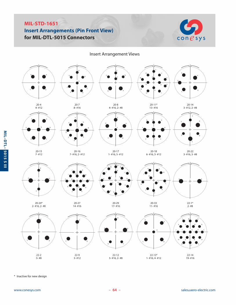
64www.conesys.com [email protected]
MIL–D
TL–
5015 S III
MIL-STD-1651Insert Arrangements (Pin Front View)for MIL-DTL-5015 Connectors
Insert Arrangement Views
– –
20-157- #12
20-24*2- #16, 2- #8
A
B
C
D
EF
G
H
J
K
L
M
N
I
20-2714- #16
AB
C
D
E
T
FG
H
J
K
L
M
N
P
RS
20-2917- #16
A
B
C
D
E
F
H
J
K
L
M
20-3311- #16
20-167- #16, 2- #12
20-171- #16, 5- #12
20-186- #16, 3- #12
20-223- #16, 3- #8
AB
22-1*2- #8
22-23- #8
A
B
C
D
E
F
G
HI
A
B
CD
E
F
G
A
BC
D
E
F
A
B
CDE
F
G H
I
A
B
C
D
E
F
A
B
C
D
A
BC
A
BC
22-93- #12
22-123- #16, 2- #8
A
B
CD
E
22-13*1- #16, 4- #12
A
BC
D
E
A
B
C
D
EF
G
H
J
K
L M
N
P
RS
V
U
T
22-1419- #16
A
B
C
DE
G
H
F
A
BC
D
20-44- #12
20-78- #16
A
B
C
D
EF
20-84- #16, 2- #8
A
B C
D
E F
G H
J
K
L
M
N
20-11*13- #16
A
BC
D
E
20-143- #12, 2- #8
* Inactive for new design

65www.conesys.com [email protected]
MIL–D
TL–
5015 S III
MIL-STD-1651Insert Arrangements (Pin Front View)
for MIL-DTL-5015 Connectors
Insert Arrangement Views
– –
AB
A
B
CD
E
F
G
A
B
C
D
E
F
H
J K
G
A
BC
D
A
B
C
D
E
F
G
A B C D
JE F H
K L M N P Q
R S T U V
W X Y Z
G
24-714- #16, 2- #12
24-9*2- #4
24-107- #8
24-116- #12, 3- #8
24-123- #12, 2- #4
24-209- #16, 2- #12
24-219- #16, 1- #8
24-224- #8
24-277- #16
24-2824- #16
A
B
CL
D
EF
H
G
J
K
A B C
D E F
H IG
A
B
C
D
E
AB
C
D
E
F
G
H
I
J
K
L
M
N
O
P
B
A
C
D
E
F
G
H
22-188- #16
A
B
JC
D
E
F
G
H A
BC
D
E
FG
22-271- #8, 8- #16
22-33*7- #16
AB
C
D
EF
G
H
J
K
L
M
N
P
22-1914- #16
A
B
CDE
F
G H
J
22-20*9- #16
A
BC
D
22-224- #8
A
B
C
D
E
F
G
H
22-238- #12
A
B
CD
E
F
G
24-27- #12
A
B
C
D
24-43- #16, 1- #0
A
B
C
D
E
FH
G
24-68- #12
* Inactive for new design

66www.conesys.com [email protected]
MIL–D
TL–
5015 S III
MIL-STD-1651Insert Arrangements (Pin Front View)for MIL-DTL-5015 Connectors
Insert Arrangement Views
– –
28-16- #12, 3- #8
28-212- #16, 2- #12
28-33- #8
28-52- #16, 1- #12, 2- #4
28-82- #12, 10- #16
28-96- #16, 6- #12
28-1118- #16, 4- #12
28-1226- #16
28-1535- #16
28-16*20- #16
28-196- #16, 4- #12
28-204- #16, 10- #12
28-2137- #16
28-223- #16, 3- #4
32-13- #12, 2- #0
A
P
B
C
D
EF
G
H
J
K
L
M
N
A B
C
DEF
H
JG
A
BC
A
B
CD
E
A
B
CD
E
F
G
H
J
KL
M
A
B
C
DE
F
G
H
J
K
LM
A
B
C
D
E
F
G
H
I
J
K
L
M
N
P
R
S
T
U
V
W
X
A
B
C
D
E
F
GH
J
K
L
M
N
P
R
S
T
U
V
WX
Y
Z
a
b
d
A
a b c
d e f g h
l
j k
m
B
C D E F G
H J K L M N
P R S T U V W
X Y Z
A B
C
D
EFG
H
J
K
L M
N
PQR
S
T
UV
A B
C
E
G
H
J
K
L
M
A
B
C
D
E
F
G
H
J
K
LM
N
P
A B C D
E F G H J
K L M N P R
S T U V W X Z
a b c d e f
g h j k mn
p rs
A
B
C
DE
FA
B
CD
E
32-34- #16, 2- #12,2- #4, 1- #0
A B C
D
E
F
GH
J
* Inactive for new design

67www.conesys.com [email protected]
MIL–D
TL–
5015 S III
MIL-STD-1651Insert Arrangements (Pin Front View)
for MIL-DTL-5015 Connectors
Insert Arrangement Views
– –
32-5*2- #0
32-728- #16, 7- #12
32-8*24- #16, 6- #12
32-10*3- #16, 2- #8,
2- #4
32-156- #12, 2- #0
32-174- #4
32-2254- #16
32-635- #4
32-7346- #16
36-33- #12, 3- #0
36-54- #0
A
B
32-616- #16, 2- #12,3- #8, 2- #4
A
B
C
D
E
F
G
H
I
J
K
L
M
N
O
P
R
S
T
U
V
W
X
Y
Z
a
b
c
d
e
A
B
C
D
A
B
C
D
E
F
A
B C
D E
F
G
H
A
B
C
D
E
A
BC
D
A
B
CD
G
F
E
A BC D
E FG H
I JKL M
N
PO R S
T
U V
W X
A
B
C
D
E
F
G
H
I
J
K
L
M
N
O
P
R
S
T
UV
W
X
Y
Z
a
b
c
d
e
f
g
h
j
k
A BC D E
F G H J
X Y
KL M
N P ROS T U V W
Z ab c d e f
g h j k
m n p q r
ys t u v
w xz AA
AB
AC
ADAF AG
AE
12
3
4
5
6
7
8
9101112
13
14
15
16
17
18
19
2021
22
23
2425
26
27
282930
31
32
33
34
35
36
37
38
39
4041
42
43
44
45
46
* Inactive for new design

68www.conesys.com [email protected]
MIL–D
TL–
5015 S III
MIL-STD-1651Insert Arrangements (Pin Front View)for MIL-DTL-5015 Connectors
Insert Arrangement Views
– –
36-914- #16, 14- #12,
2- #8, 1- #4
36-1048- #16 40-10
16- #16, 9- #8,4- #4
40-5685- #16
A
B
C
D
E
H
F
G
I
J
K
L
M
N
O
P
R
S
T
U
V
W
X
Y
Z
a
b
c
d
e
f
A B
C D E F G
H J K L M N
O P Q R S T U
V W X Y Z a b c
d e f g h j k
m n p q r s
t u v w x
y z
A
BC D
E
FG
H
I
J K
L
M N OP Q
R
S T
U
VW X
Y
Z a
b
c
A B C D
E F H J K L M
N P R S T U V W
X Y Z a b c d f g
h j ki m n p q r s
t u v w x y z AA AB
AC AD AE AF AH AJ AK AL AM AN
AP AR AS AT AU AV AW AX AY
AZ BA BB BC BD BE BF BH
BJ BK BL BM BN BP BR
BS BT BU BV
36-64- #4, 2- #0
36-740- #16, 7- #12
36-846- #16, 1- #12
A
B
C
D
E
F
A BC D E
F G
H I J
K L M N
OP R S T
U V W X
Y Z a b c
md e f g
h jt
k
n p
u w vr s
xz
y
A
BC
D EF
G HI J K LM
N O P RS T U V
W XY Z a
b c d e
fg h
y
jk
w
mn
x
p
z
rs tu
v

69www.conesys.com [email protected]
MIL–D
TL–
26482 S 2
MIL-DTL-26482Features and Application
Series 2
– –
Features and Application
MIL-DTL-26482 Series 2, bayonet coupling, rear-removablecrimp contact connectors were designed as an upgrade toMIL-DTL-26482 Series 1. Series 2 connectors are inter-mountable and interchangeable with both solder andfront-release crimp Series 1. They are also identical to theinactivated MIL-DTL- 83723 Series I connectors.
Series 2 connectors are widely used on commercial, militaryand aerospace systems requiring general-purpose, miniaturecylindrical bayonet coupling connectors.
This family of connectors is offered in 4 receptacle-mountingstyles. They include narrow flange wall mounting receptacles,wide flange wall mounting receptacles, cable connectingreceptacles and jam nut mounting receptacles which incorpo-rate “O” ring seals, designed for rear panel “D” hole mounting.
Plugs are available in two designs, with and without RFIgrounding.
Thirty-three insert arrangements per MIL-STD-1669 aretooled and qualified to MIL-DTL-26482 Series 2, utilizing 3 to 61 M39029 contacts. Contacts come in sizes 20, 16 and12, terminating wire sizes from 24 to 12 gauge.
These connectors are available in wide range of shell materials and finishes. Aluminum shells are offered in electroless nickel, olive drab cadmium and black anodic.Other finishes such as zinc nickel are available upon requestto commercial callouts only. In addition, we offer passivatedstainless steel shells with standard environment-resistinginserts (commercial callouts only), and for highly corrosiveenvironments, nickel-aluminum-bronze shells with standardenvironment-resisting inserts (commercial callouts only).
Universal I/R Tool – A single, expendable plastic tool is usedfor both insertion and removal of contacts.
Insert Polarization – Alternate insert clocking positions aidin mating of adjacent connectors having identical insertarrangement.
Closed-Entry Socket Insert – Hard dielectric socket facehas lead-in chamfers for positive alignment of pins (evenpartially bent within pre-established limits) with sockets.
Interfacial Pin Insert Seal – Raised moisture barriersaround each pin, which mate into lead-in chamfers of hardface socket insert, provide individual contact sealing.Interfacial seal is never touched by service tools.
Elastomer Wire Sealing Grommet – Sealing over a widerange of wire diameters is assured by a triple wire seal ineach cavity at the rear of the connector.
Superior Contact Stability – Rear release crimp contactsystem features a stamped beryllium-copper retaining clipcaptivated by molded-in shoulders of each contact cavity inthe insulator. A rear-inserted M81969 plastic tool expandsthe tines beyond the shoulder, releasing the contact.
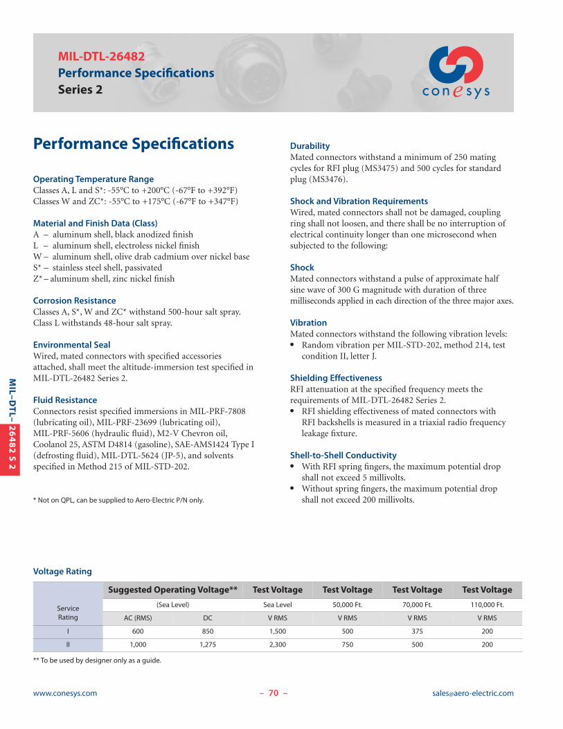
70www.conesys.com [email protected]
MIL–D
TL–
26482 S 2
MIL-DTL-26482Performance SpecificationsSeries 2
– –
Performance Specifications
Operating Temperature RangeClasses A, L and S*: -55°C to +200°C (-67°F to +392°F)Classes W and ZC*: -55°C to +175°C (-67°F to +347°F)
Material and Finish Data (Class)A – aluminum shell, black anodized finishL – aluminum shell, electroless nickel finishW – aluminum shell, olive drab cadmium over nickel baseS* – stainless steel shell, passivatedZ*– aluminum shell, zinc nickel finish
Corrosion ResistanceClasses A, S*, W and ZC* withstand 500-hour salt spray.Class L withstands 48-hour salt spray.
Environmental SealWired, mated connectors with specified accessoriesattached, shall meet the altitude-immersion test specified inMIL-DTL-26482 Series 2.
Fluid ResistanceConnectors resist specified immersions in MIL-PRF-7808(lubricating oil), MIL-PRF-23699 (lubricating oil), MIL-PRF-5606 (hydraulic fluid), M2-V Chevron oil,Coolanol 25, ASTM D4814 (gasoline), SAE-AMS1424 Type I(defrosting fluid), MIL-DTL-5624 (JP-5), and solvents specified in Method 215 of MIL-STD-202.
* Not on QPL, can be supplied to Aero-Electric P/N only.
DurabilityMated connectors withstand a minimum of 250 matingcycles for RFI plug (MS3475) and 500 cycles for standardplug (MS3476).
Shock and Vibration RequirementsWired, mated connectors shall not be damaged, couplingring shall not loosen, and there shall be no interruption ofelectrical continuity longer than one microsecond whensubjected to the following:
ShockMated connectors withstand a pulse of approximate halfsine wave of 300 G magnitude with duration of three milliseconds applied in each direction of the three major axes.
VibrationMated connectors withstand the following vibration levels:� Random vibration per MIL-STD-202, method 214, test
condition II, letter J.
Shielding EffectivenessRFI attenuation at the specified frequency meets therequirements of MIL-DTL-26482 Series 2.� RFI shielding effectiveness of mated connectors with
RFI backshells is measured in a triaxial radio frequencyleakage fixture.
Shell-to-Shell Conductivity� With RFI spring fingers, the maximum potential drop
shall not exceed 5 millivolts.� Without spring fingers, the maximum potential drop
shall not exceed 200 millivolts.
ServiceRating
Suggested Operating Voltage** Test Voltage Test Voltage Test Voltage Test Voltage
(Sea Level) Sea Level 50,000 Ft. 70,000 Ft. 110,000 Ft.
AC (RMS) DC V RMS V RMS V RMS V RMS
I 600 850 1,500 500 375 200
II 1,000 1,275 2,300 750 500 200
Voltage Rating
** To be used by designer only as a guide.

71www.conesys.com [email protected]
MIL–D
TL–
26482 S 2
MIL-DTL-26482Part Number Development
Series 2
Military and Aero-Electric Part Number Development
– –
* Not on QPL, can be supplied to Aero part number only. Consult factoryfor availability.
Note 1: Each connector is furnished with contacts unlessordered less contacts (L/C) as follows: One spare contact forinserts requiring 2 to 26 of each contact and two spares forinserts with 27 or more of each size, and a minimum of onesealing plug up to 15% of the number of contacts. In addition,one plastic insetion/removal tool of each size is included.
Note 2: Proper part number marking has no “0” in front of single digit shell size ( 8) and no “0” after the dashbetween shell size and single digit layout. Example of each:J MS3470W8-33P and J MS3470W10-6P. In both “N” fornormal was omitted. As indicated above, “J” or “JAN” mustbe marked in front of MIL part number.
Note 3: Insert layouts 8-2, 8-3 and 8-4 can only be orderedto Aero-Electric part number. Non standard contacts arerequired and to avoid confusion are sold “with contacts”only. See page 80 for the correct contact part numbers.
Mil. Prefix MS34 70 L 12 - 10 P WAero Prefix AE7 70 L 12 - 10 P W -340Shell type
70 = Narrow flange receptacle
71 = Cable connecting receptacle
72 = Wide flange receptacle
74 = Jam nut receptacle
75 = RFI grounding plug
76 = Straight plug
Class (Material and Finish)A = Aluminum shell, black anodized finish (not available in RFI plug)
L = Aluminum shell, electroless nickel finish
W = Aluminum shell, olive drab cadmium over electroless nickel base
S* = Stainless steel shell, passivated (Aero part number only)
Z* = Aluminum shell, zinc nickel finish (Aero part number only)
Shell Size8, 10, 12, 14, 16, 18, 20, 22 or 24
Insert ArrangementSee pages 82 thru 85
Contact StyleP = Pin
S = Socket
A = Pin connector less pins (with intent to use non-std contact)
B = Socket connector less sockets (with intent to use non-std contacts)
PolarizationN = Normal (not included in part number)
W, X, Y or Z = Alternate insert polarizations (see pages 82 thru 83 for position availability)
Modification (applies to Aero part numbers only)01 = Less contacts (is not marked on the part)
340 = Connector kitted with M85049/31-XXX E-nut
341 = Connector kitted with M85049/52-1-XXX straight clamp
342 = Connector kitted with M85049/51-1-XXX right angle clamp
Consult factory for other modifications

72www.conesys.com [email protected]
MIL–D
TL–
26482 S 2
MS3470Narrow Flange ReceptacleAE770
Bayonet Coupling, Crimp Removable, Rear Release
– –
Page 71 Completed Part NumberPage 80 Contacts, Sealing Plugs and ToolsPages 84, 85 Insert ArrangementsPage 70 Performance SpecificationsPages 82, 83 Insert Availability and Contact InformationPage 82 Polarization
Note: Maximum grommet O.D. is same as � C MAX on page 74.
BLUE COLOR BAND
MAX PANEL THICKNESS & SCREWHEAD.087(2.21) S.S. 8–18.212(5.38) S.S. 20–24
MAX PANEL THICKNESS.125(3.18)
BLUE COLOR BAND
B
4x [ CMOUNTING HOLES
MASTER KEYWAY
[ H
4 MINOR KEYWAYS
3 BAYONET PINS
F
AMAX
3 ACCESSORY TEETH
.190 (4.83)
.130 (3.30)GROMMET EXTENSION
G ACCESSORY THREAD
E .290(7.37)MINFULLTHREAD
DMAX
ShellSize
A B � C D E F G � H
+.016 +.41 Accessory ThreadMaximum (TP) ±.005 ±.13 Maximum ±.016 ±.41 -.015 -.38 Class 2A ±.003 ±.08
inch mm inch mm inch mm inch mm inch mm inch mm inch mm
8 .828 21.03 .594 15.09 .120 3.05 1.215 30.86 .062 1.57 .446 11.33 1/2-20UNF .471 11.96
10 .954 24.23 .719 18.26 .120 3.05 1.215 30.86 .062 1.57 .446 11.33 5/8-24UNEF .588 14.94
12 1.047 26.59 .812 20.62 .120 3.05 1.215 30.86 .062 1.57 .446 11.33 3/4-20UNEF .748 19.00
14 1.141 28.98 .906 23.01 .120 3.05 1.215 30.86 .062 1.57 .446 11.33 7/8-20UNEF .873 22.17
16 1.234 31.34 .969 24.61 .120 3.05 1.215 30.86 .062 1.57 .446 11.33 1-20UNEF .998 25.35
18 1.328 33.73 1.062 26.97 .120 3.05 1.215 30.86 .062 1.57 .446 11.33 1-1/16-18UNEF 1.123 28.52
20 1.453 36.91 1.156 29.36 .120 3.05 1.275 32.39 .094 2.39 .571 14.50 1-3/16-18UNEF 1.248 31.70
22 1.578 40.08 1.250 31.75 .120 3.05 1.275 32.39 .094 2.39 .571 14.50 1-5/16-18UNEF 1.373 34.87
24 1.703 43.26 1.375 34.93 .147 3.73 1.275 32.39 .094 2.39 .604 15.34 1-7/16-18UNEF 1.498 38.05

73www.conesys.com [email protected]
MIL–D
TL–
26482 S 2
MS3471Cable Connecting Receptacle
AE771
Bayonet Coupling, Crimp Removable, Rear Release
– –
Note: Maximum grommet O.D. is same as � C MAX on page 74.
Page 71 Completed Part NumberPage 80 Contacts, Sealing Plugs and ToolsPages 84, 85 Insert ArrangementsPage 70 Performance SpecificationsPages 82, 83 Insert Availability and Contact InformationPage 82 Polarization
BLUE COLOR BANDS
[ B
MASTER KEYWAY
AMAX .290
(7.37)MINFULLTHREAD
4 MINOR KEYWAYS
3 BAYONET PINS
[ F
E D
CMAX
G ACCESSORY THREAD
3 ACCESSORY TEETH
.190 (4.83)
.130 (3.30)GROMMET EXTENSION
ShellSize
A � B C D E � F G
+.016 +.41 Accessory ThreadMaximum ±.020 ±.51 Maximum ±.016 ±.41 -.015 -.38 ±.003 ±.08 Class 2A
inch mm inch mm inch mm inch mm inch mm inch mm
8 .828 21.03 .938 23.83 1.215 30.86 .062 1.57 .446 11.33 .471 11.96 1/2-20UNF
10 .954 24.23 1.062 26.97 1.215 30.86 .062 1.57 .446 11.33 .588 14.94 5/8-24UNEF
12 1.047 26.59 1.156 29.36 1.215 30.86 .062 1.57 .446 11.33 .748 19.00 3/4-20UNEF
14 1.141 28.98 1.250 31.75 1.215 30.86 .062 1.57 .446 11.33 .873 22.17 7/8-20UNEF
16 1.234 31.34 1.344 34.14 1.215 30.86 .062 1.57 .446 11.33 .998 25.35 1-20UNEF
18 1.328 33.73 1.438 36.53 1.215 30.86 .062 1.57 .446 11.33 1.123 28.52 1-1/16-18UNEF
20 1.453 36.91 1.562 39.67 1.275 32.39 .094 2.39 .571 14.50 1.248 31.70 1-3/16-18UNEF
22 1.578 40.08 1.688 42.88 1.275 32.39 .094 2.39 .571 14.50 1.373 34.87 1-5/16-18UNEF
24 1.703 43.26 1.812 46.02 1.275 32.39 .094 2.39 .604 15.34 1.498 38.05 1-7/16-18UNEF

74www.conesys.com [email protected]
MIL–D
TL–
26482 S 2
MS3472Wide Flange ReceptacleAE772
Bayonet Coupling, Crimp Removable, Rear Release
– –
Page 71 Completed Part NumberPage 80 Contacts, Sealing Plugs and ToolsPages 84, 85 Insert ArrangementsPage 70 Performance SpecificationsPages 82, 83 Insert Availability and Contact InformationPage 82 Polarization
ShellSize
A B � C D E F G � H
+.016 +.41 Accessory ThreadMaximum (TP) Maximum Maximum ±.016 ±.41 -.015 -.38 Class 2A ±.003 ±.08
inch mm inch mm inch mm inch mm inch mm inch mm inch mm
8 1.065 27.05 .734 18.64 .305 7.75 1.215 30.86 .062 1.57 .477 12.12 1/2-20UNF .471 11.96
10 1.141 28.98 .812 20.62 .405 10.29 1.215 30.86 .062 1.57 .477 12.12 5/8-24UNEF .588 14.94
12 1.266 32.16 .938 23.83 .531 13.49 1.215 30.86 .062 1.57 .477 12.12 3/4-20UNEF .748 19.00
14 1.360 34.54 1.031 26.19 .665 16.89 1.215 30.86 .062 1.57 .477 12.12 7/8-20UNEF .873 22.17
16 1.453 36.91 1.125 28.58 .790 20.07 1.215 30.86 .062 1.57 .477 12.12 1-20UNEF .998 25.35
18 1.532 38.91 1.203 30.56 .869 22.07 1.215 30.86 .062 1.57 .477 12.12 1-1/16-18UNEF 1.123 28.52
20 1.688 42.88 1.297 32.94 .994 25.25 1.275 32.39 .094 2.39 .571 14.50 1-3/16-18UNEF 1.248 31.70
22 1.766 44.86 1.375 34.93 1.119 28.42 1.275 32.39 .094 2.39 .571 14.50 1-5/16-18UNEF 1.373 34.87
24 1.891 48.03 1.500 38.10 1.244 31.60 1.275 32.39 .094 2.39 .604 15.34 1-7/16-18UNEF 1.498 38.05
[ .150±.005([ 3.81±.13)MOUNTING HOLES 4 MINOR KEYWAYS
3 BAYONET PINS
MASTER KEYWAY
B
AMAX
[ H
F E
DMAX
G ACCESSORY THREAD
.190 (4.83)
.130 (3.30)GROMMET EXTENSION
3 ACCESSORY TEETH
[ CMAXGROMMET
.290(7.37)MINFULLTHREAD
BLUE COLOR BAND
MAX PANEL THICKNESS & SCREWHEAD.118(3.00) S.S. 8–18.212(5.38) S.S. 20–24
BLUE COLOR BAND
MAX PANEL THICKNESS.125(3.18)

.190 (4.83)
.130 (3.30)GROMMET EXTENSION
.290(7.37)MINFULL THREAD
[ B
A C MAX
GACCESSORY THREAD(SAME AS FOR MS3472 ON PREVIOUS PAGE) H THREAD
ED
3X REAR ACCESSORY TEETH
BLUE COLOR BAND
S.S. 8–18
S.S. 20–24
PANEL THICKNESS.187(4.75).062(1.57)
.250(6.35)
.062(1.57)
"O" RING
BLUE COLOR BAND
3 BAYONET PINS
HEX NUTPER MS3186EXCEPT FOR THICKNESS
FFLAT
.125(3.18)
.108(2.74)
MASTERKEYWAY
75www.conesys.com [email protected]
MIL–D
TL–
26482 S 2
MS3474Jam Nut Receptacle
AE774
Bayonet Coupling, Crimp Removable, Rear Release
– –
Page 71 Completed Part NumberPage 80 Contacts, Sealing Plugs and ToolsPages 84, 85 Insert ArrangementsPage 70 Performance SpecificationsPages 82, 83 Insert Availability and Contact InformationPage 82 Polarization
ShellSize
A � B C D E F H
+.000 +.00 +.000 +.00 Flat Jam Nut-.031 -.79 -.031 -.79 Maximum ±.005 ±.13 Thread
inch mm inch mm inch mm inch mm inch mm inch mm UNEF-2A
8 .954 24.23 1.078 27.38 1.215 30.86 .113/.086 2.87/2.18 .707/.658 17.96/16.71 .525 13.34 9/16-24
10 1.078 27.38 1.203 30.56 1.215 30.86 .113/.086 2.87/2.18 .707/.658 17.96/16.71 .650 16.51 11/16-24
12 1.266 32.16 1.391 35.33 1.215 30.86 .113/.086 2.87/2.18 .707/.658 17.96/16.71 .813 20.65 7/8-20
14 1.391 35.33 1.516 38.51 1.215 30.86 .113/.086 2.87/2.18 .707/.658 17.96/16.71 .937 23.80 1-20
16 1.516 38.51 1.641 41.68 1.215 30.86 .113/.086 2.87/2.18 .707/.658 17.96/16.71 1.061 26.95 1-1/8-18
18 1.641 41.68 1.766 44.86 1.215 30.86 .113/.086 2.87/2.18 .707/.658 17.96/16.71 1.186 30.12 1-1/4-18
20 1.828 46.43 1.954 49.63 1.275 32.39 .148/.096 3.76/2.44 .772/.721 19.61/18.31 1.311 33.30 1-3/8-18
22 1.954 49.63 2.078 52.78 1.275 32.39 .148/.096 3.76/2.44 .772/.721 19.61/18.31 1.436 36.47 1-1/2-18
24 2.078 52.78 2.203 55.96 1.275 32.39 .148/.096 3.76/2.44 .772/.721 19.61/18.31 1.561 39.65 1-5/8-18
Note: Maximum grommet O.D. is same as � E MAX on page 76.
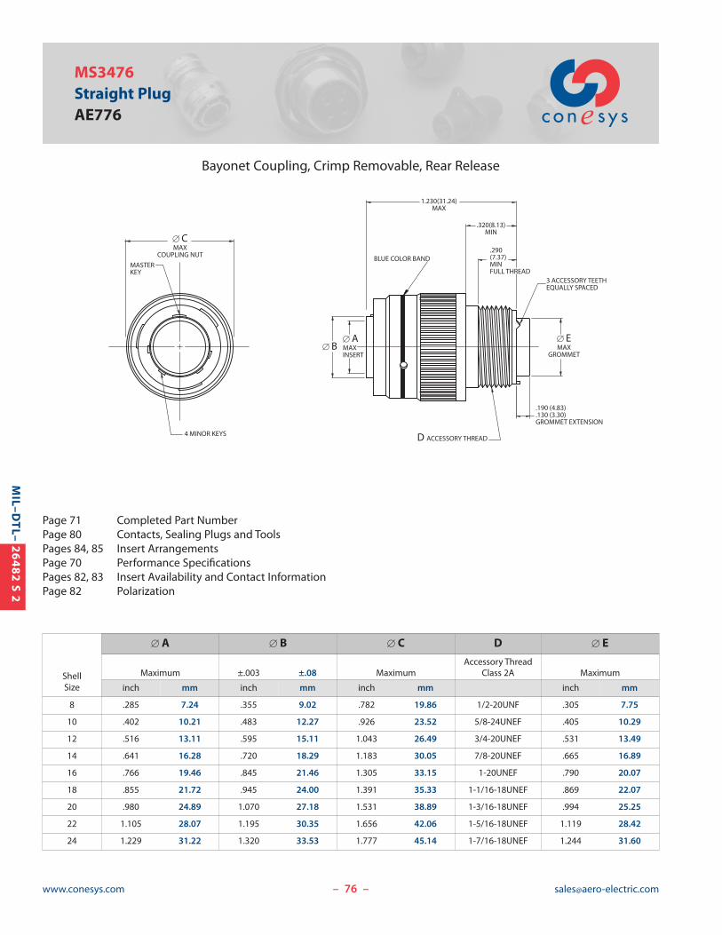
76www.conesys.com [email protected]
MIL–D
TL–
26482 S 2
MS3476Straight PlugAE776
Bayonet Coupling, Crimp Removable, Rear Release
– –
Page 71 Completed Part NumberPage 80 Contacts, Sealing Plugs and ToolsPages 84, 85 Insert ArrangementsPage 70 Performance SpecificationsPages 82, 83 Insert Availability and Contact InformationPage 82 Polarization
BLUE COLOR BAND
.190 (4.83)
.130 (3.30)GROMMET EXTENSION
1.230(31.24)MAX
.320(8.13)MIN
.290(7.37)MINFULL THREAD
MASTER KEY
4 MINOR KEYS
[ CMAX
COUPLING NUT
[ AMAXINSERT
[ B
D ACCESSORY THREAD
3 ACCESSORY TEETHEQUALLY SPACED
[ EMAX
GROMMET
ShellSize
� A � B � C D � E
Accessory ThreadMaximum ±.003 ±.08 Maximum Class 2A Maximum
inch mm inch mm inch mm inch mm
8 .285 7.24 .355 9.02 .782 19.86 1/2-20UNF .305 7.75
10 .402 10.21 .483 12.27 .926 23.52 5/8-24UNEF .405 10.29
12 .516 13.11 .595 15.11 1.043 26.49 3/4-20UNEF .531 13.49
14 .641 16.28 .720 18.29 1.183 30.05 7/8-20UNEF .665 16.89
16 .766 19.46 .845 21.46 1.305 33.15 1-20UNEF .790 20.07
18 .855 21.72 .945 24.00 1.391 35.33 1-1/16-18UNEF .869 22.07
20 .980 24.89 1.070 27.18 1.531 38.89 1-3/16-18UNEF .994 25.25
22 1.105 28.07 1.195 30.35 1.656 42.06 1-5/16-18UNEF 1.119 28.42
24 1.229 31.22 1.320 33.53 1.777 45.14 1-7/16-18UNEF 1.244 31.60

77www.conesys.com [email protected]
MIL–D
TL–
26482 S 2
MS3475RFI Grounding Plug
AE775
Bayonet Coupling, Crimp Removable, Rear Release
– –
Page 71 Completed Part NumberPage 80 Contacts, Sealing Plugs and ToolsPages 84, 85 Insert ArrangementsPage 70 Performance SpecificationsPages 82, 83 Insert Availability and Contact InformationPage 82 Polarization
RFI STRIP
[ AMAXINSERT
[ B
[ CMAX
COUPLING NUT
1.230(31.24)MAX
BLUE COLOR BAND
.190 (4.83)
.130 (3.30)GROMMET EXTENSION
[ EMAX
GROMMET
.290(7.37)MINFULL THREAD
D ACCESSORY THREAD
MASTER KEY
4 MINOR KEYS
3 ACCESSORY TEETHEQUALLY SPACED
.320(8.13)MIN
ShellSize
� A � B � C D � E
Accessory ThreadMaximum ±.003 ±.08 Maximum Class 2A Maximum
inch mm inch mm inch mm inch mm
8 .285 7.24 .355 9.02 .782 19.86 1/2-20UNF .305 7.75
10 .402 10.21 .483 12.27 .926 23.52 5/8-24UNEF .405 10.29
12 .516 13.11 .595 15.11 1.043 26.49 3/4-20UNEF .531 13.49
14 .641 16.28 .720 18.29 1.183 30.05 7/8-20UNEF .665 16.89
16 .766 19.46 .845 21.46 1.305 33.15 1-20UNEF .790 20.07
18 .855 21.72 .945 24.00 1.391 35.33 1-1/16-18UNEF .869 22.07
20 .980 24.89 1.070 27.18 1.531 38.89 1-3/16-18UNEF .994 25.25
22 1.105 28.07 1.195 30.35 1.656 42.06 1-5/16-18UNEF 1.119 28.42
24 1.229 31.22 1.320 33.53 1.777 45.14 1-7/16-18UNEF 1.244 31.60

78www.conesys.com [email protected]
MIL–D
TL–
26482 S 2
AC3475Arctic Coupling Nut, RFI Plug
Bayonet Coupling, Crimp Removable, Rear Release
AC3475 – 10- 7 P N
– –
Page 80 Contacts, Sealing Plugs and ToolsPages 84, 85 Insert ArrangementsPage 70 Performance SpecificationsPages 82, 83 Insert Availability and Contact InformationPage 82 Polarization
Note: AC3475 Arctic Coupling Nut, RFI Plug is available to Aero-Electric part number only. Mating part is AC3474which is same as AE774 on page 75. Additional mates areAC3470 (same as AE770 on page 72), AC3471 (same asAE771 on page 73)and AC3472 (same as AE772 on page 74).
Shell Size
� A � B � C D � E
Accessory ThreadMaximum ±.003 ±.08 Maximum Class 2A Maximum
inch mm inch mm inch mm inch mm
8 .285 7.24 .355 9.02 .900 22.86 1/2-20UNF .305 7.75
10 .402 10.21 .483 12.27 1.010 25.65 5/8-24UNEF .405 10.29
12 .516 13.11 .595 15.11 1.180 29.97 3/4-20UNEF .531 13.49
14 .641 16.28 .720 18.29 1.310 33.27 7/8-20UNEF .665 16.89
16 .766 19.46 .845 21.46 1.510 38.35 1-20UNEF .790 20.07
18 .855 21.72 .945 24.00 1.620 41.15 1-1/16-18UNEF .869 22.07
20 .980 24.89 1.070 27.18 1.740 44.20 1-3/16-18UNEF .994 25.25
22 1.105 28.07 1.195 30.35 1.850 46.99 1-5/16-18UNEF 1.119 28.42
24 1.229 31.22 1.320 33.53 1.980 50.29 1-7/16-18UNEF 1.244 31.60
RFI STRIP
[ B
[ CMAX
COUPLING NUT
1.230(31.24)MAX
.190 (4.83)
.130 (3.30)GROMMET EXTENSION
[ E
MAXGROMMET
.290(7.37)MINFULL THREAD
D ACCESSORY THREAD
MASTER KEY
4 MINOR KEYS
3 ACCESSORY TEETHEQUALLY SPACED
[ AMAXINSERT
Aero Prefix
Class (Material and Finish)– = Aluminum shell, cadmium olive drab over nickelZ = Aluminum shell, zinc nickel finish
Shell Size8, 10, 12, 14, 16, 18, 20, 22 or 24
PolarizationN = Normal (N included in part number marking)
A, B, C, D, E or F (Alternate key positions) and W, X, Y or Z (Alternate insert clocking positions)
Contact StyleP = Pin
S = Socket
LayoutSee pages 82 thru 85

79www.conesys.com [email protected]
MIL–D
TL–
26482 S 2
MIL-DTL-26482 Series 2Flange and Jam Nut Receptacles
Panel Cutouts
Panel Cutouts
– –
Flange and Jam Nut Mounting Dimensions
Note: For � C and � E, MS3470 and MS3472 call out for tolerance of ±.010 (±.25), however we recommend ±.005 (±.13).
ShellSize
� A B � C D � E F � G
±.005 ±.13 (TP) ±.010 ±.25 (TP) ±.010 ±.25 ±.005 ±.13 ±.005 ±.13
inch mm inch mm inch mm inch mm inch mm inch mm inch mm
8 .568 14.43 .594 15.09 .120 3.05 .734 18.64 .150 3.81 .536 13.61 .572 14.53
10 .685 17.40 .719 18.26 .120 3.05 .812 20.62 .150 3.81 .661 16.79 .697 17.70
12 .864 21.95 .812 20.62 .120 3.05 .938 23.83 .150 3.81 .824 20.93 .895 22.73
14 .989 25.12 .906 23.01 .120 3.05 1.031 26.19 .150 3.81 .948 24.08 1.010 25.65
16 1.113 28.27 .969 24.61 .120 3.05 1.125 28.58 .150 3.81 1.072 27.23 1.135 28.83
18 1.238 31.45 1.062 26.97 .120 3.05 1.203 30.56 .150 3.81 1.197 30.40 1.260 32.00
20 1.363 34.62 1.156 29.36 .120 3.05 1.297 32.94 .150 3.81 1.322 33.58 1.385 35.18
22 1.488 37.80 1.250 31.75 .120 3.05 1.375 34.93 .150 3.81 1.447 36.75 1.510 38.35
24 1.615 41.02 1.375 34.93 .147 3.73 1.500 38.10 .150 3.81 1.572 39.93 1.635 41.53
B [ G
[ E
D
[ C [ A
F
[ A
MS3470(AE770) MS3474(AE774) MS3472(AE772)

80www.conesys.com [email protected]
MIL–D
TL–
26482 S 2
MIL-DTL-26482Contacts, Tools and Seal PlugsSeries 2
Contacts, Plastic Insertion/Removal Tools and Seal Plugs
Crimping and Metal Insertion/Extraction Tools
Contact and Wire Data
Note: Test Current and Maximum Voltage Drop whentested with silver-plated wire at 25°C.
* Size 20 contacts for 8–2, 8–3 and 8–4 layouts are only available toAero-Electric part numbers. Connectors incorporating these three layouts are only sold to Aero-Electric callouts (AE770, AE771, AE772,AE774, AE775, AE776, AC3470, AC3471, AC3472, AC3474 and AC3475).Standard size 20 contacts M39029/4-110 and M39029/5-115 will notwork in these 3 layouts.
– –
ContactSize
Application Pin Contacts Socket Contacts Seal Plugs Insertion/Removal ToolsPlastic
Type Military No. Military No. Military No. Military No.
20 Power/Signal M39029/4-110 M39029/5-115 MS27488-20-1 M81969/14-11
16 Power/Signal M39029/4-111 M39029/5-116 MS27488-16-1 M81969/14-03
12 Power/Signal M39029/4-113 M39029/5-118 MS27488-12-1 M81969/14-04
20* Power/Signal 5291-022-204H 5091-022-204H MS27488-20-1 M81969/39-01
ContactSize
Crimp Tool Positioner Positioner Insertion Tool Extraction ToolFor Pin Contacts For Socket Contacts Metal Metal
Military No. Military No. Military No. Military No. Military No.
20M22520/1-01 M22520/1-02 M22520/1-02
M81969/8-205 M81969/8-206M22520/2-01 M22520/2-02 M22520/2-02
16 M22520/1-01 M22520/1-02 M22520/1-02 M81969/8-207 M81969/8-208
12 M22520/1-01 M22520/1-02 M22520/1-02 M81969/8-209 M81969/8-210
20*M22520/1-01 M22520/1-02 M22520/1-02
M81969/8-205 M81969/8-206M22520/2-01 M22520/2-02 M22520/2-02
ContactSize
Test Current Voltage Crimp Well Data Wire Range Finished Wire � RangeDC Test Max. Drop Well Dia. Minimum Well Dept Minimum Maximum
Amps Millivolts inch inch mm AWG mm2 inch mm inch mm
20 7.5 55 .049 ±.001 .155 3.94 24-20 .20-.52 .040 1.02 .083 2.11
16 13.0 49 .067 ±.001 .250 6.35 20-16 .52-1.31 .053 1.35 .103 2.62
12 23.0 42 .100 ±.002 .250 6.35 14-12 2.08-3.31 .097 2.46 .158 4.01

81www.conesys.com [email protected]
MIL–D
TL–
26482 S 2
MIL-DTL-26482Contact Installation Instructions
Series 2
– –
Contact InstallationInstructions
Crimping Contacts 1. Select the appropriate crimp tool and ensure that the
proper crimp head positioner is used.
2. Cycle the tool to be sure the indentors are open.
3. Determine the correct selector setting for the wire sizefrom the data plate on the positioner (turret head assembly) and set the selector knob on the crimp tool to match.
4. Place the contact, mating end first, into the tool.
5. Insert the stripped wire into the hollow end of the contact.Be sure the wire is inserted as far as it will go.
6. Close the tool completely to crimp. Unless the tool isclosed completely, the tool will not release the contact.
7. Remove the crimped contact from the tool. Check theinspection hole to verify that the wire is fully inserted.
Insertion of Contacts1. Before inserting the contacts, unscrew the accessories
(clamps, backshells or adapters) from rear of plug orreceptacle. Slide the hardware over the wire bundle in the proper order for reassembly after all the contacts are inserted.
2. To assist insertion of contacts, lubricate insulator (grommet) cavities with isopropyl alcohol. Alcohol willevaporate and will not leave a conductive film. Caution:Never use any lubricant other than isopropyl alcohol.
3. Place the correct insertion tool on the contact so that thewire runs along the groove in the tool. (Tool tip will buttagainst the shoulder.) Hold the plug or receptacle bodyfirmly.
4. Beginning with a center cavity, insert the contact into the insulator with a slow, even pressure until the contactsnaps into position. Make sure the contact and tool areheld perpendicular to the face of the insert during thecontact installation or the grommet could be damaged.
4.1 If contacts are not inserted all the way prior toremoving insertion tool, do not try to reinsert theinsertion tool. Instead, remove the contact and tryagain; otherwise reinserting the insertion tool maydamage the inside of the contact cavity.
5. Remove tool and check the face of the connector forproper contact installation. Proper installation may alsobe checked by pulling back lightly on the wire to makesure the contact is properly seated.
CompletionAfter all the cavities have been filled, slide the hardware backinto position on the connector and tighten.
Extraction of Contacts (Rework)1. Slide the hardware back over the wire bundle.
2. Select the appropriate tool. Place the wire into theextraction tool of the pin or socket.
3. Slowly slide the extraction tool down wire into the contactcavities until the tool tip bottoms against the contactshoulder, expanding the clip retaining tines. Hold the wirefirmly in the tool and pull the wired contact and toolstraight out of the rear of the insulator.
Size Pin Contact Socket Contact Basic Crimp Tool Pin Positioner Socket Positioner Insertion/Removal Tool
20 M39029/4-110 M39029/5-115M22520/1-01 M22520/1-02 Red M22520/1-02 Red
M81969/14-11M22520/2-01 M22520/2-02 M22520/2-02
16 M39029/4-111 M39029/5-116 M22520/1-01 M22520/1-02 Blue M22520/1-02 Blue M81969/14-03
12 M39029/4-113 M39029/5-118 M22520/1-01 M22520/1-02 Yellow M22520/1-02 Yellow M81969/14-04
20* 5291-022-204H 5091-022-204HM22520/1-01 M22520/1-02 Red M22520/1-02 Red
M81969/39-01M22520/2-01 SK2/2** SK2/2**
* Aero-Electric proprietary size 20 contacts used in 8-2, 8-3 and 8-4 layouts only.** Daniels Manufacturing part number.

82www.conesys.com [email protected]
MIL–D
TL–
26482 S 2
MIL-DTL-26482 Series 2Polarization, Insert Availability & Contact Informationper MIL-STD-1669
Insert Availability, Contact Information and Clocking Positions
– –
Polarization (Insert Clocking)1. In the normal insert clocking position (position N), the
insert centerline coincides with the centerline of the master keyway (key) of the shell: L = 0°.
2. In the alternate clocking positions (W, X, Y and Z), the pin insert (viewing from mating side) is rotatedclockwise relative to the centerline of the master keyway (key) of the shell.
3. The socket insert is rotated counter-clockwise.4. Plugs have keys; receptacles have keyways.
Note: Be careful with alternate positions. See table below forposition availability on layouts of interest.
* Not qualified to MIL-DTL-26482 Series 2. These layouts were designedto mate with solder Series 1 connectors using proprietary Aero-Electriccontacts (not QPL’d to M39029) and to avoid confusion are sold only“with contacts”.
** Non MIL-STD-1669 layouts, available to Aero-Electric part numbersonly and utilize standard M39029 contacts. These layouts were originally designed for use in AC3475 Arctic Coupling RFI plugs andAC3474 jam nut receptacles.
InsertArrangement
Aero-Electric Total Contact Quantity Service Insert PositionsStatus No. of By Size In Degrees
QPL'd Tooled Contacts 20 16 12 Rating N W X Y Z
8-2* No Yes 2 2 I 0 58 122 — —
8-3* No Yes 3 3 I 0 60 210 — —
8-4* No Yes 4 4 I 0 45 — — —
8-33 Yes Yes 3 3 I 0 90 — — —
8-98 Yes Yes 3 3 I 0 — — — —
10-6 Yes Yes 6 6 I 0 90 — — —
10-7** N/A Yes 7 7 I 0 90 — — —
12-3 Yes Yes 3 3 II 0 — — 180 —
12-8 Yes Yes 8 8 I 0 90 112 203 292
12-10 Yes Yes 10 10 I 0 60 155 270 295
14-2** N/A Yes 2 2 I 0 — — — —
14-4 Yes Yes 4 4 I 0 45 — — —
14-5 Yes Yes 5 5 II 0 40 92 184 273
14-9 Yes Yes 9 5 4 I 0 15 90 180 240
14-12 Yes Yes 12 8 4 I 0 43 90 — —
14-15 Yes Yes 15 14 1 I 0 17 110 155 234
14-18 Yes Yes 18 18 I 0 15 90 180 270
14-19 Yes Yes 19 19 I 0 30 165 315 —
PIN INSERTMATING FACE
(SOCKET INSERT IS OPPOSITE)
INSERTVERTICALCENTERLINE
MASTERKEYWAY (KEY)OF A SHELL
L°

83www.conesys.com [email protected]
MIL–D
TL–
26482 S 2
MIL-DTL-26482 Series 2Polarization, Insert Availability & Contact Information
per MIL-STD-1669
Insert Availability, Contact Information and Clocking Positions
– –
InsertArrangement
Aero-Electric Total Contact Quantity Service Insert PositionsStatus No. of By Size In Degrees
QPL'd Tooled Contacts 20 16 12 Rating N W X Y Z
16-8 Yes Yes 8 8 II 0 54 152 180 331
16-14 Yes Yes 14 8 6 I 0 25 78 180 240
16-23 Yes Yes 23 22 1 I 0 158 270 — —
16-26 Yes Yes 26 26 I 0 60 — 275 338
18-8 Yes Yes 8 8 I 0 180 — — —
18-11 Yes Yes 11 11 II 0 62 119 241 340
18-30 Yes Yes 30 29 1 I 0 180 193 285 350
18-32 Yes Yes 32 32 I 0 85 138 222 265
20-16 Yes Yes 16 16 II 0 238 318 333 347
20-24 Yes Yes 24 24 I 0 70 145 215 290
20-39 Yes Yes 39 37 2 I 0 63 144 252 333
20-41 Yes Yes 41 41 I 0 45 126 225 —
22-12 Yes Yes 12 12 I 0 — — — —
22-21 Yes Yes 21 21 II 0 16 135 175 349
22-41 Yes Yes 41 27 14 I 0 39 135 264 —
22-55 Yes Yes 55 55 I 0 30 142 226 314
22-95 Yes Yes 32 26 6 I 0 26 180 266 —
24-19 Yes No 19 19 II 0 30 165 315 —
24-31 Yes Yes 31 31 I 0 90 225 255 —
24-61 Yes Yes 61 61 I 0 90 180 270 324

84www.conesys.com [email protected]
MIL–D
TL–
26482 S 2
MIL-STD-1669Insert Arrangements (Pin Front View)for MIL-DTL-26482 Series 2 Connectors
Insert Arrangement Views
– –
* Not on QPL, available to Aero-Electric part number only. ** Non MIL-STD-1669 layout, available in AC3470 through AC3475 shellstyles only.
A
B
CABA
B C
D A
BC
A
B
C AB
CD
E
F
AB
G
CD
E
F A
B
C
A
H B
CD
E
F
G
A B
C
DEF
G
H
JK
A
B
C
D
AB
CD
E
A
B
C
D
E
F
G
H
J
A
B
C
DE
F
G
M
H
J
K
L
A
B
R C
D
EF
G
H
J
K
L
M
N
P
A
B
C
D
EFG
H
J
K
L
M N
P
RS
T U
A B
C
D
E
FGH
J
K
L
M
N P
R
ST
U V
A
B
C
DE
F
G
H
A
B
C
D
E
F
G
H
J
K
L
M
N P
A
B
C
D
E
FGH
J
K
L
M
NP
RS
T
UV
W
X
Y
Z
AB
C
D
E
F
GHJ
K
L
M
N
P
R
S T
U
V
WX
Y
Z
a b
c
A
B
C
DE
F
G
H
A
B
C
DE
G
H
J
K
L
F
AB
C
D
E
F
GHJ
K
L
M
N
P
RS
T
U
V
W
XY
Z
a
b
c
d
e
fg
AB
C
D
E
F
G
HJK
L
M
N
P
R
ST
UV
W
X
YZa
b
c
d
e
f
g
h
J
A
B
C
D
EF
G
H
J
K
L
M
N
PR
S
8-3*3 # 20, I
8-2*2 # 20, I
8-4*4 # 20, I
8-333 # 20, I
8-983 # 20, I
10-66 # 20, I
10-7**7 # 20, I
12-33 # 16, II
12-88 # 20, I
12-1010 # 20, I
14-44 # 12, I
14-55 # 16, II
14-95 # 20, 4 # 12, I
14-124 # 16, 8 # 20, I
14-151 # 16, 14 # 20, I
14-1818 # 20, I
14-1919 # 20, I
16-88 # 16, II
16-148 # 20, 6 # 12, I
16-231 # 16, 22 # 20, I
16-2626 # 20, I
18-88 # 12, I
18-1111 # 16, II
20-1616 # 16, II
18-3232 # 20, I
18-301 # 16, 29 # 20, I
AB
14-2**2 # 12, I
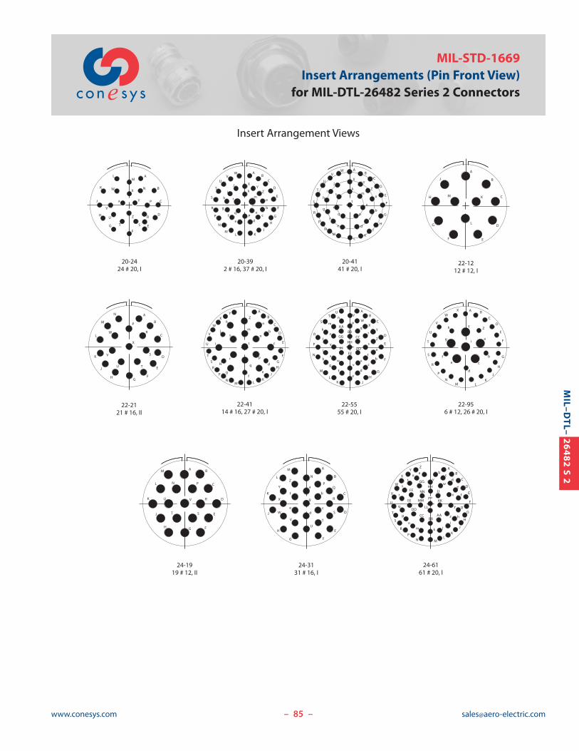
85www.conesys.com [email protected]
MIL–D
TL–
26482 S 2
MIL-STD-1669Insert Arrangements (Pin Front View)
for MIL-DTL-26482 Series 2 Connectors
Insert Arrangement Views
– –
A
B
C
D
EF
G
H
J
K
LM
N
P
R
ST
U
V
W X
Y
Z
a
20-2424 # 20, I
AB
C
D
E
F
G
H
JKL
M
N
P
R
S
T
UV
W
XY
Z
a
b
cde
f
g
h
Jk
m
nP
r
i
q
20-392 # 16, 37 # 20, I
20-4141 # 20, I
A
B
C
D
E
FGH
J
K
L
M
N
P
R
S
TU
V
W
X
22-2121 # 16, II
A
B
C
D
EF
G
H
J
K
L
M
22-1212 # 12, I
a
b
c
d
ef
g
H
j
k
m
n
Pr
s
t
AB
C
D
E
F
GH
JK
LMN
R
S
T
U
V
W
XY
Z
P
i
q
22-4114 # 16, 27 # 20, I
AB
C
D
E
F
GH
JKL
M
N
P
R
ST
UV
WX
Y
Zl
a
b
c
de
fg
h
k
m
np
r
s
t
uv
wx
y
z
i
qAABB
CC
DDEE
FF
GGHH
22-5555 # 20, I
A B
C
D
E
F
G
H
JK
LMN
P
R
S
T
U
V
WX
Y Z
a
b
c
d
ef
g
h
i
22-956 # 12, 26 # 20, I
A B
C
D
E
FGH
J
K
L
M
N P
R
ST
U V
24-1919 # 12, II
A
B
C
D
E
FG
H
J
K
L
M
N
P
R
S
TU
V
W
X
Y
Z
a
b
cd
e
f
g
Q
24-3131 # 16, I
AB
C
D
E
F
G
H
J
KL
MNP
R
S
T
U
V
W
X
YZ
AABB
CC
DD
EE
FF
GGHH
JJ
LL
KKMM
NN
PP
a bc
d
e
f
g
h
jkmn
p
r
s
tu
vw
x
y
z
i
q
24-6161 # 20, I
AB
C
D
E
F
G
H
JK
LM
N
P
R
S
T
U
VW
XY
Z
a
b
c
de
f
g
h
jk
m
n
p
r
si
q
t

86www.conesys.com [email protected]
MIL–D
TL–
83723 S III
MIL-DTL-83723 Series IIIFeatures and ApplicationBayonet and Threaded Coupling
– –www.conesys.com [email protected]
Features and Application
MIL-DTL-83723 Series III family offers connectors with bayonet and threaded coupling including lanyard-releasequick-disconnects. These connectors combine the best featuresof MIL-DTL-26500 and NAS 1599 miniature connectorspecifications. They are intermateable with both bayonet andthreaded 26500 connectors (exception: shell size 8, threadedcoupling only) and have the added advantage provided by therear-release contact retention system.
AE833 connectors are widely used on commercial, militaryand aerospace systems requiring general-purpose, miniaturecylindrical bayonet or threaded coupling connectors. In addition, Series III threaded connectors with self-lockingplugs are well suited for engine applications.
This family of connectors (bayonet as well as threaded) isoffered in wall mount receptacles as well as jam nut mountedreceptacles which incorporate “O” ring seals, designed for rearpanel “D” hole mounting.
Series III bayonet-coupling plugs are available in two designs- with and without RFI grounding. Threaded coupling plugsare offered with and without RFI grounding, self-locking and RFI/self-locking. In addition we offer quick-disconnect (lanyard release) plugs, which mate with threaded receptaclesvia an adapter.
Thirty-one insert arrangements per MIL-STD-1554 aretooled and qualified to MIL-DTL-83723 Series III, utilizing 2 to 61 M39029 contacts. Contacts come in sizes 20, 16 and12, terminating wire sizes from 24 to 12 gauge.
These connectors are available in wide range of shell materialsand finishes. Aluminum shells are offered in electroless nickel,olive drab cadmium and black anodic. Other finishes such aszinc nickel are available upon request to commercial calloutsonly. In addition, we offer passivated stainless steel shellswith both standard and firewall-rated inserts, and for highlycorrosive environments, nickel-aluminum-bronze shellswith standard environment-resisting inserts (commercialcallouts only).
Universal I/R Tool – A single, expendable plastic tool is usedfor both insertion and removal of contacts.
Shell Polarization – Alternate key/keyway positions preventcross mating of adjacent connectors having same insertarrangement.
Closed-Entry Socket Insert – Hard dielectric socket face haslead-in chamfers for positive alignment of pins (even partiallybent within pre-established limits) with sockets.
Interfacial Pin Insert Seal – Raised moisture barriers aroundeach pin, which mate into lead-in chamfers of hard facesocket insert, provide individual contact sealing. Interfacialseal is never touched by service tools.
Elastomer Wire Sealing Grommet – Sealing over a widerange of wire diameters is assured by a triple wire seal in eachcavity at the rear of the connector.
Superior Contact Stability – Rear release crimp contact system features a stamped beryllium-copper retaining clipcaptivated by molded-in shoulders of each contact cavity inthe insulator. A rear-inserted M81969 plastic tool expands thetines beyond the shoulder, releasing the contact.

87www.conesys.com [email protected]
MIL–D
TL–
83723 S III
MIL-DTL-83723 Series IIIPerformance Specifications
Bayonet and Threaded Coupling
– –
Performance Specifications
Operating Temperature RangeClasses A and R: -65°C to +200°C (-85°F to +392°F)Class W: -65°C to +175°C (-85°F to +347°F)Classes G and K: -65°C to +200°C (-85°F to +392°F)Classes N and S: -65°C to +200°C (-85°F to +392°F)
Material and Finish Data (Class)A – aluminum shell, black anodized finishG – stainless steel shell, passivatedK – stainless steel shell, passivated, firewallR – aluminum shell, electroless nickel finishS – stainless steel shell, passivated, firewall, and 360° teethW– aluminum shell, olive drab cadmium over nickel baseN– stainless steel shell, electrodeposited nickel, firewall, and360° teeth
Corrosion ResistanceClass W withstands 500-hour salt spray.Class R withstands 48-hour salt spray.
Environmental SealWired, mated connectors with specified accessoriesattached, shall meet the altitude-immersion test specified by MIL-DTL-83723 Series III.
Fluid ResistanceConnectors resist specified immersions in MIL-PRF-7808(lubricating oil), MIL-PRF-23699 (lubricating oil), MIL-PRF-5606 (hydraulic fluid), M2-V Chevron oil,Coolanol 25, MIL-DTL-83133 (turbine fuel JP-8), MIL-DTL-5624 (turbine fuels JP-4 and JP-5), SAE-AMS1424Type I (defrosting fluid), and other solvents and cleaningagents.
Voltage Rating
DurabilityMated connectors withstand a minimum of 500 matingcycles for bayonet coupling straight plug (M83723/75, 76);250 mating cycles for bayonet coupling RFI plug(M83723/77, 78); and 250 cycles for all threaded couplingplugs (M83723/86, 87, 91, 92, 95, 96, 97, 98).
Shock and Vibration RequirementsWired, mated connectors shall not be damaged, couplingring shall not loosen, and there shall be no interruption ofelectrical continuity longer than one microsecond whensubjected to the following:
ShockMated connectors withstand a pulse of approximate halfsine wave of 300 G ± 15 percent magnitude with durationof 3 ± 1 milliseconds applied in three axes.
VibrationMated connectors withstand the following vibration levels:� Random vibration per MIL-STD-1344, method 2005,test condition VI, letter J.
Shielding EffectivenessRFI attenuation at the specified frequency meets therequirements of MIL-DTL-83723 Series III.� RFI shielding effectiveness of mated connectors with RFIbackshells is measured in a triaxial radio frequency leak-age fixture.
Shell-to-Shell Conductivity (Except class A)� With RFI spring fingers, the maximum potential dropshall not exceed 5 millivolts.
� Without spring fingers, the maximum potential dropshall not exceed 200 millivolts.
* To be used by designer only as a guide.
ServiceRating
Suggested Operating Voltage* Test Voltage Test Voltage Test Voltage Test Voltage
(Sea Level) Sea Level 50,000 Ft. 70,000 Ft. 110,000 Ft.
AC (RMS) DC V RMS V RMS V RMS V RMS
I 600 850 1500 500 375 200
II 900 1250 2300 750 500 200

88www.conesys.com [email protected]
MIL–D
TL–
83723 S III
MIL-DTL-83723 Series IIIPart Number DevelopmentBayonet Coupling
Military and Aero-Electric Part Number Development
– –
Note 1: Each connector is furnished with contacts unlessordered less contacts (L/C) as follows: One spare contact forinserts requiring 2 to 26 of each contact and two spares forinserts with 27 or more of each size, and a minimum of onesealing plug up to 15% of the number of contacts of eachsize. In addition, one insertion/removal tool of each size isincluded.
Note 2: Proper part number marking has no “0” in front ofsingle digit shell size (8), but it does include the “0” in frontof single digit layout. Examples: M83723/72W803N andM83723/77G10056. Please note that in this series “N” fornormal is included in part number marking.
Mil. Prefix M83723/ 71 R 12 12 N
Aero Prefix AE833 71 R 12 12 N -340Shell type
71 = Wall mount receptacle with socket contacts
72 = Wall mount receptacle with pin contacts
73 = Jam nut receptacle with socket contacts
74 = Jam nut receptacle with pin contacts
75 = Straight plug with socket contacts
76 = Straight plug with pin contacts
77 = RFI grounding plug with socket contacts
78 = RFI grounding plug with pin contacts
Class (Material and Finish)A = Aluminum shell, black anodized finish (not available in 77 and 78 RFI plugs)
G = Stainless stell shell, passivated
R = Aluminum shell, electroless nickel finish
W= Aluminum shell, olive drab cadmium over electroless nickel finish
Shell Size (SS)8, 10, 12, 14, 16, 18, 20, 22 or 24
Insert ArrangementSee pages 106 thru 108
Polarization (Keying)N = Normal
6, 7, 8, 9 or Y (Alternate keyed positions, Y is not available in SS 8)
1, 2, 3, 4 or 5 (Clocked insert polarizations within normally keyed shell, not approved for new design, n/a in SS 8)
Modification (applies to Aero part numbers only)01 = Less contacts (Part is bagged and tagged, but not marked with 01)
340 = Connector kitted with M85049/31-XXX E-nut
341 = Connector kitted with M85049/52-1-XXX straight clamp
342 = Connector kitted with M85049/51-1-XXX right angle clamp
Consult factory for other modifications

89www.conesys.com [email protected]
MIL–D
TL–
83723 S III
M83723/71, 72Wall Mounting Receptacle
AE83371, 72
Bayonet Coupling, Crimp Removable, Rear Release
– –
MASTERKEYWAY
4x MINOR KEYS
[ D
3x BAYONET PINSEQUALLY SPACED
4x [ CMOUNTINGHOLES
3 ACCESSORY TEETHEQUALLY SPACED
E ACCESSORY THREAD
[ FMAX
GROMMET
.290(7.37) MIN FULL THREAD
A
B
1.300(33.02)MAX
.728(18.49)
.708(17.98)
.190(4.83)
.130(3.30)GROMMETEXTENSION
.072(1.83)
.052(1.32)
BLUE COLOR BANDS
Page 88 Completed Part NumberPage 104 Contacts, Sealing Plugs and ToolsPages 107, 108 Insert ArrangementsPage 87 Performance SpecificationsPage 106 Insert Availability and Contact InformationPage 102 Polarization
ShellSize
A B � C � D E � F
+.000 +.00 Accessory Thread±.005 ±.13 (TP) ±.005 ±.13 -.005 -.13 Class 2A Maximum
inch mm inch mm inch mm inch mm inch mm
8 .812 20.62 .594 15.09 .120 3.05 .536 13.61 1/2-20UNF .305 7.75
10 .937 23.80 .719 18.26 .120 3.05 .659 16.74 5/8-24UNEF .405 10.29
12 1.031 26.19 .812 20.62 .120 3.05 .829 21.06 3/4-20UNEF .531 13.49
14 1.125 28.58 .906 23.01 .120 3.05 .898 22.81 7/8-20UNEF .665 16.89
16 1.250 31.75 .969 24.61 .120 3.05 1.025 26.04 1-20UNEF .790 20.07
18 1.343 34.11 1.062 26.97 .120 3.05 1.131 28.73 1-1/16-18UNEF .869 22.07
20 1.437 36.50 1.156 29.36 .120 3.05 1.256 31.90 1-3/16-18UNEF .994 25.25
22 1.562 39.67 1.250 31.75 .120 3.05 1.381 35.08 1-5/16-18UNEF 1.119 28.42
24 1.703 43.26 1.375 34.93 .149 3.78 1.506 38.25 1-7/16-18UNEF 1.244 31.60

90www.conesys.com [email protected]
MIL–D
TL–
83723 S III
M83723/73, 74Jam Nut ReceptacleAE83373, 74
Bayonet Coupling, Crimp Removable, Rear Release
– –
BLUE COLOR BAND
BLUE COLOR BAND
.781(19.84)
.761(19.33).190(4.83).130(3.30)
GROMMETEXTENSION
HEX NUTPER MS3186
3 ACCESSORY TEETHEQUALLY SPACED
1.300(33.02) MAX
4x MINOR KEYWAYS
MASTERKEYWAY "O" RING
[ D
EMOUNTING FLAT
G ACCESSORY THREADF JAM NUT THREAD
[ CMAX
GROMMET
[ BMAX
AMAX
PANEL THICKNESS:.125(3.18).062(1.58)
Page 88 Completed Part NumberPage 104 Contacts, Sealing Plugs and ToolsPages 107, 108 Insert ArrangementsPage 87 Performance SpecificationsPage 106 Insert Availability and Contact InformationPage 102 Polarization
ShellSize
A � B � C � D E F G
+.000 +.00 Jam Nut Thread Accessory ThreadMaximum Maximum Maximum -.005 -.13 ±.003 ±.08 Class 2A Class 2A
inch mm inch mm inch mm inch mm inch mm
8 .979 24.87 1.068 27.13 .305 7.75 .536 13.61 .593 15.06 5/8-20UN 1/2-20UNF
10 1.104 28.04 1.192 30.28 .405 10.29 .659 16.74 .718 18.24 3/4-20UNEF 5/8-24UNEF
12 1.291 32.79 1.380 35.05 .531 13.49 .829 21.06 .905 22.99 15/16-20UNEF 3/4-20UNEF
14 1.391 35.33 1.505 38.23 .665 16.89 .898 22.81 .968 24.59 1-20UNEF 7/8-20UNEF
16 1.516 38.51 1.630 41.40 .790 20.07 1.025 26.04 1.093 27.76 1-1/8-20UN 1-20UNEF
18 1.641 41.68 1.756 44.60 .869 22.07 1.131 28.73 1.217 30.91 1-1/4-18UNEF 1-1/16-18UNEF
20 1.766 44.86 1.860 47.24 .994 25.25 1.256 31.90 1.342 34.09 1-3/8-18UNEF 1-3/16-18UNEF
22 1.954 49.63 2.086 52.98 1.119 28.42 1.381 35.08 1.467 37.26 1-1/2-18UNEF 1-5/16-18UNEF
24 2.079 52.81 2.160 54.86 1.244 31.60 1.506 38.25 1.592 40.44 1-5/8-18UNEF 1-7/16-18UNEF
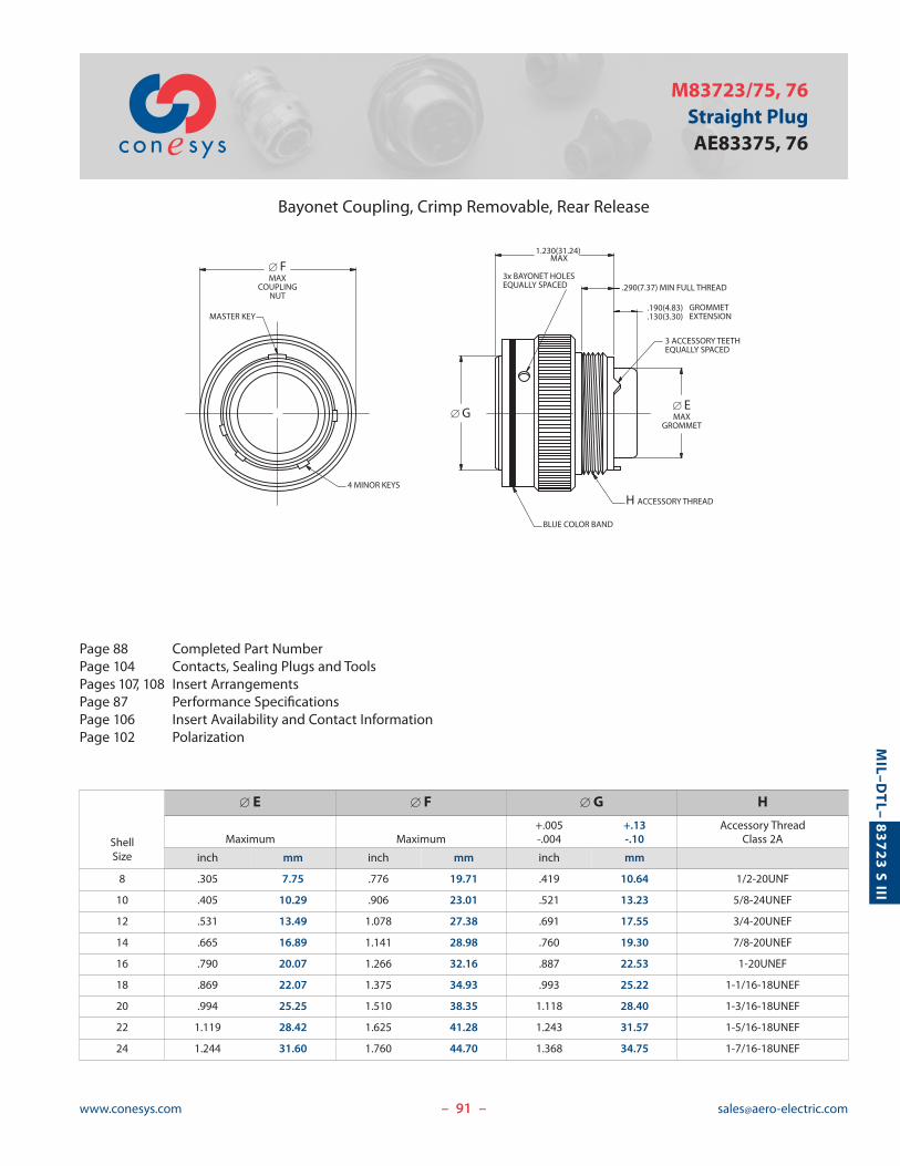
91www.conesys.com [email protected]
MIL–D
TL–
83723 S III
M83723/75, 76Straight PlugAE83375, 76
Bayonet Coupling, Crimp Removable, Rear Release
– –
BLUE COLOR BAND
MASTER KEY
4 MINOR KEYS
3x BAYONET HOLESEQUALLY SPACED
3 ACCESSORY TEETHEQUALLY SPACED
H ACCESSORY THREAD
[ EMAX
GROMMET
.290(7.37) MIN FULL THREAD
.190(4.83)
.130(3.30)GROMMETEXTENSION
[ FMAX
COUPLINGNUT
[ G
1.230(31.24)MAX
Page 88 Completed Part NumberPage 104 Contacts, Sealing Plugs and ToolsPages 107, 108 Insert ArrangementsPage 87 Performance SpecificationsPage 106 Insert Availability and Contact InformationPage 102 Polarization
ShellSize
� E � F � G H
+.005 +.13 Accessory ThreadMaximum Maximum -.004 -.10 Class 2A
inch mm inch mm inch mm
8 .305 7.75 .776 19.71 .419 10.64 1/2-20UNF
10 .405 10.29 .906 23.01 .521 13.23 5/8-24UNEF
12 .531 13.49 1.078 27.38 .691 17.55 3/4-20UNEF
14 .665 16.89 1.141 28.98 .760 19.30 7/8-20UNEF
16 .790 20.07 1.266 32.16 .887 22.53 1-20UNEF
18 .869 22.07 1.375 34.93 .993 25.22 1-1/16-18UNEF
20 .994 25.25 1.510 38.35 1.118 28.40 1-3/16-18UNEF
22 1.119 28.42 1.625 41.28 1.243 31.57 1-5/16-18UNEF
24 1.244 31.60 1.760 44.70 1.368 34.75 1-7/16-18UNEF
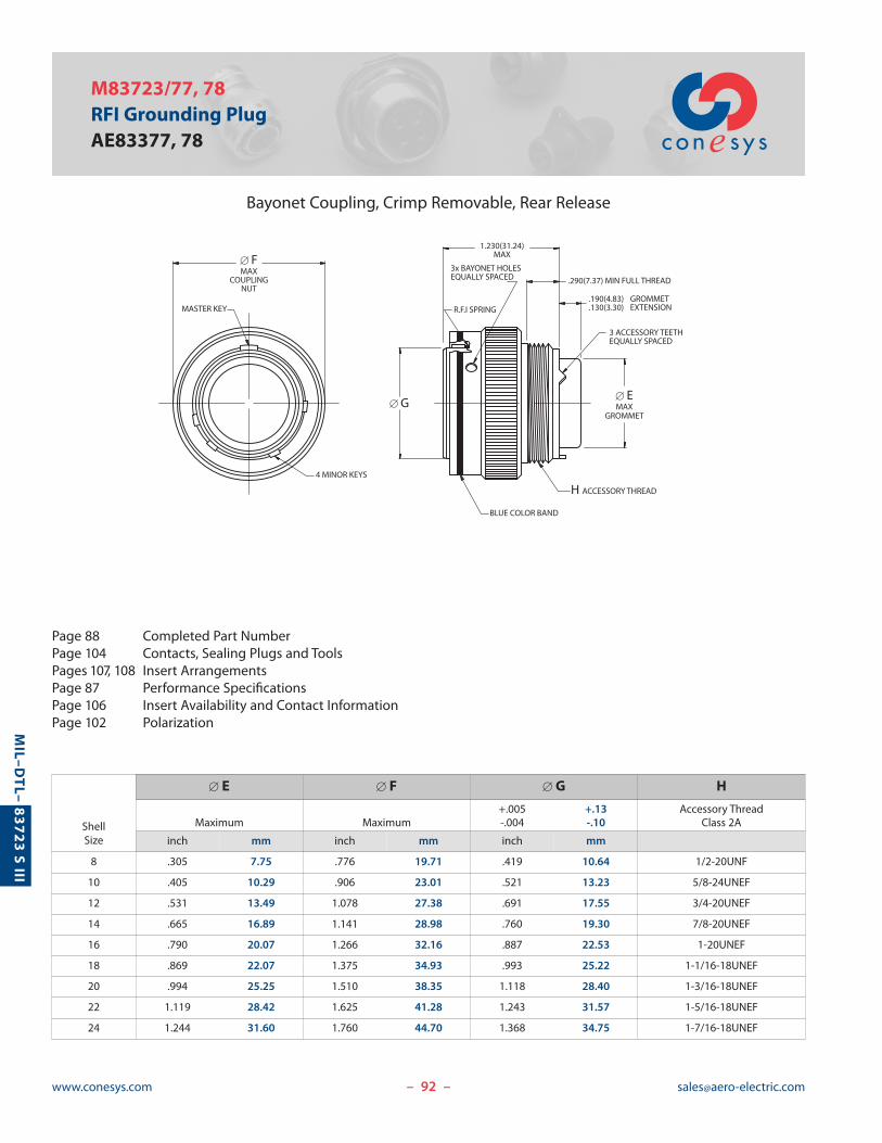
92www.conesys.com [email protected]
MIL–D
TL–
83723 S III
M83723/77, 78RFI Grounding PlugAE83377, 78
Bayonet Coupling, Crimp Removable, Rear Release
– –
Page 88 Completed Part NumberPage 104 Contacts, Sealing Plugs and ToolsPages 107, 108 Insert ArrangementsPage 87 Performance SpecificationsPage 106 Insert Availability and Contact InformationPage 102 Polarization
ShellSize
� E � F � G H
+.005 +.13 Accessory ThreadMaximum Maximum -.004 -.10 Class 2A
inch mm inch mm inch mm
8 .305 7.75 .776 19.71 .419 10.64 1/2-20UNF
10 .405 10.29 .906 23.01 .521 13.23 5/8-24UNEF
12 .531 13.49 1.078 27.38 .691 17.55 3/4-20UNEF
14 .665 16.89 1.141 28.98 .760 19.30 7/8-20UNEF
16 .790 20.07 1.266 32.16 .887 22.53 1-20UNEF
18 .869 22.07 1.375 34.93 .993 25.22 1-1/16-18UNEF
20 .994 25.25 1.510 38.35 1.118 28.40 1-3/16-18UNEF
22 1.119 28.42 1.625 41.28 1.243 31.57 1-5/16-18UNEF
24 1.244 31.60 1.760 44.70 1.368 34.75 1-7/16-18UNEF
3x BAYONET HOLESEQUALLY SPACED .290(7.37) MIN FULL THREAD
.190(4.83)
.130(3.30)GROMMETEXTENSION
BLUE COLOR BAND
R.F.I SPRING
3 ACCESSORY TEETHEQUALLY SPACED
H ACCESSORY THREAD
[ EMAX
GROMMET[ G
1.230(31.24)MAX
MASTER KEY
4 MINOR KEYS
[ FMAX
COUPLINGNUT

93www.conesys.com [email protected]
MIL–D
TL–
83723 S III
MIL-DTL-83723 Series IIIPart Number Development
Threaded Coupling
Military and Aero-Electric Part Number Development
– –
Note 1: Each connector is furnished with contacts unlessordered less contacts (L/C) as follows: One spare contact forinserts requiring 2 to 26 of each contact and two spares forinserts with 27 or more of each size, and a minimum of onesealing plug up to 15% of the number of contacts of eachsize. In addition, one insertion/removal tool of each size isincluded.
Note 2: Proper part number marking has no “0” in front ofsingle digit shell size (8), but it does include the “0” in frontof single digit layout. Examples: M83723/95G803N andM83723/98S10056. Please note that in this series “N” fornormal is included in part number marking.
Note 3: Shell type M83723/70 (AE83370 Receptacle Adapter)is not listed above, see page 101.
Mil. Prefix M83723/ 95 R 12 12 N
Aero Prefix AE833 95 R 12 12 N -340Shell type
82 = Wall mount receptacle with socket contacts
83 = Wall mount receptacle with pin contacts
84 = Jam nut receptacle with socket contacts
85 = Jam nut receptacle with pin contacts
86 = Straight plug with socket contacts
87 = Straight plug with pin contacts
91 = RFI grounding plug with socket contacts
92 = RFI grounding plug with pin contacts
95 = Self-locking plug with socket contacts
96 = Self-locking plug with pin contacts
97 = Self-locking, RFI grounding plug with socket contacts
98 = Self-locking, RFI grounding plug with pin contacts
68 = Lanyard release, quick-disconnect plug, pin (not available in K & S classes)
69 = Lanyard release, quick-disconnect plug, socket (not available in K & S classes)
Class (Material and Finish)A = Aluminum shell, black anodized finish (Not available in 91, 92, 97 & 98 RFI plugs)
G = Stainless steel shell, passivated (n/a in 97 & 98)
K = Stainless steel shell, passivated, with firewall rated insert (n/a in 91, 92, 97 & 98)
R = Aluminum shell, electroless nickel finish (n/a in 97 & 98 to mil number)
W = Aluminum shell, olive drab cadmium over nickel base (n/a in 97 & 98 to mil number)
S = Stainless steel shell, passivated, full teeth, firewall insert (n/a in 86, 87, 91, 92, 95 & 96)
Shell Size (SS)8, 10, 12, 14, 16, 18, 20, 22 or 24 (and shell size 28 available in Aero p/n only)
Insert ArrangementSee pages 106-108
Polarization (Keying)N = Normal
6, 7, 8, 9 or Y (Alternate keyed positions, Y is not availabe in SS 8)
1, 2, 3, 4 or 5 (Clocked insert polarizations within normally keyed shell, not approved for new design, n/a in SS 8)
Modification (applies to Aero part numbers only)01 = Less contacts (Part is bagged and tagged, but not marked with 01)
340 = Connector kitted with M85049/31-XXX E-nut
341 = Connector kitted with M85049/52-1-XXX straight clamp
342 = Connector kitted with M85049/51-1-XXX right angle clamp
Consult factory for other modifications

H No. OF TEETHCLASSES: “N” & “S” ONLY
E ACCESSORY THREAD
.290(7.37) MIN FULL THREAD
.160(4.06) GROMMET
.010(0.25) EXTENSION
1.340(34.04) MAXCLASSES: “N” & “S” ONLY
E4 MINOR KEYWAYS
1.248(31.70)MAX
4x [ CMOUNTING HOLES
B
A
D MATING THREAD
.728(18.49)
.708(17.98)
FULL MATE INDICATOR COLOR: RED
[ FMAX
GROMMET[ FMAX
GROMMET
.290(7.37) MINFULL THREAD
.072(1.83)
.052(1.32)
.190(4.83) GROMMET
.130(3.30) EXTENSION
ACCESSORY THREAD
MASTERKEYWAY
BLUE COLOR BANDS
3 ACCESORY TEETHEQUALLY SPACED
PANEL THICKNESS: .125(3.18) MAX
94www.conesys.com [email protected]
MIL–D
TL–
83723 S III
M83723/82, 83Wall Mounting ReceptacleAE83382, 83
Threaded Coupling, Crimp Removable, Rear Release
– –
Page 93 Completed Part NumberPage 104 Contacts, Sealing Plugs and ToolsPages 107, 108 Insert ArrangementsPage 87 Performance SpecificationsPage 106 Insert Availability and Contact InformationPage 102 Polarization
ShellSize
A B � C D E � F H
+.005 +.13 Mating Thread Accessory Thread No. of±.005 ±.13 (TP) -.004 -.10 Class 2A Class 2A Maximum Teeth
inch mm inch mm inch mm inch mm
8 .812 20.62 .594 15.09 .120 3.05 9/16-24UNEF 1/2-20UNF .305 7.75 12
10 .937 23.80 .719 18.26 .120 3.05 11/16-24UNEF 5/8-24UNEF .405 10.29 15
12 1.031 26.19 .812 20.62 .120 3.05 7/8-20UNEF 3/4-20UNEF .531 13.49 21
14 1.125 28.58 .906 23.01 .120 3.05 15/16-20UNEF 7/8-20UNEF .665 16.89 24
16 1.250 31.75 .969 24.61 .120 3.05 1-1/16-18UNEF 1-20UNEF .790 20.07 30
18 1.343 34.11 1.062 26.97 .120 3.05 1-3/16-18UNEF 1-1/16-18UNEF .869 22.07 33
20 1.437 36.50 1.156 29.36 .120 3.05 1-5/16-18UNEF 1-3/16-18UNEF .994 25.25 36
22 1.562 39.67 1.250 31.75 .120 3.05 1-7/16-18UNEF 1-5/16-18UNEF 1.119 28.42 39
24 1.703 43.26 1.375 34.93 .149 3.78 1-9/16-18UNEF 1-7/16-18UNEF 1.244 31.60 42
28 2.000 50.80 1.562 39.67 .149 3.78 1-13/16-16UN 1-3/4-18UNS 1.475 37.47 54
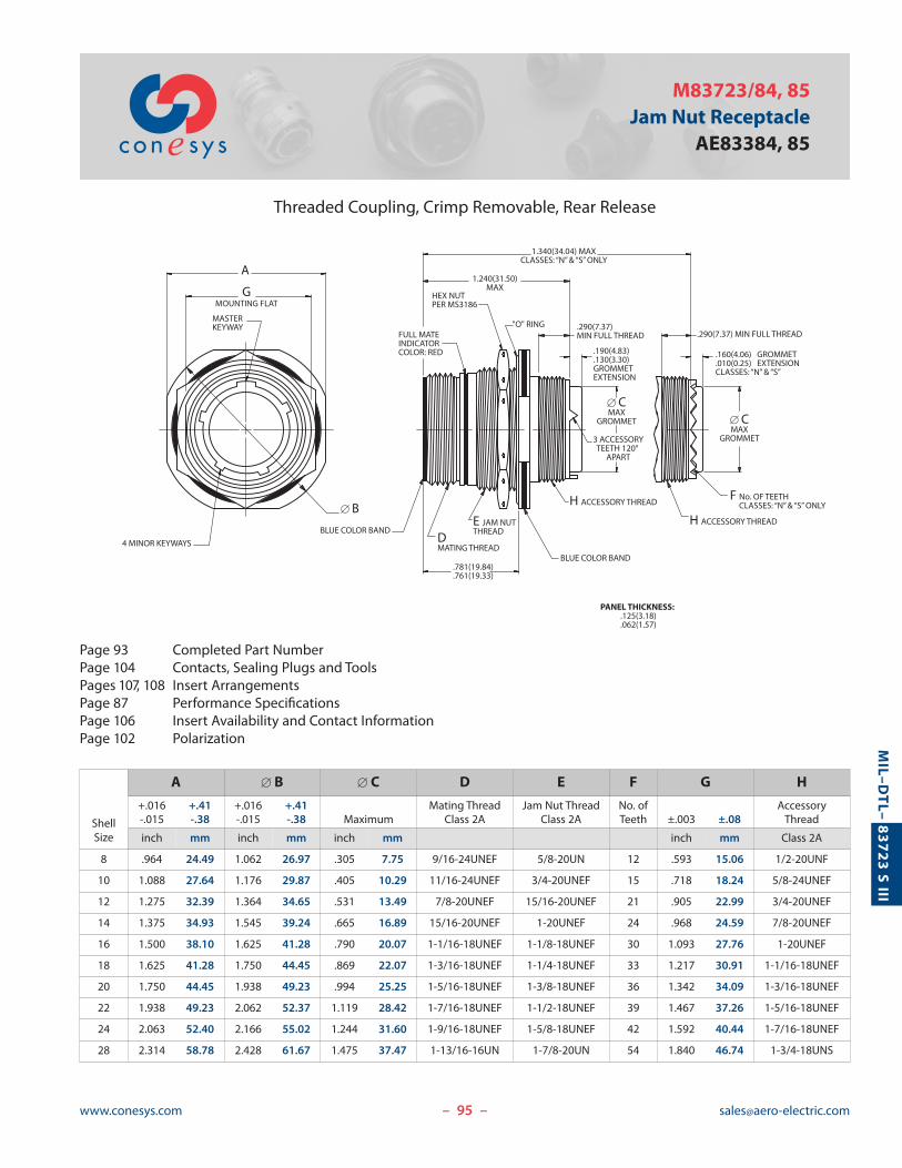
H ACCESSORY THREAD
.190(4.83)
.130(3.30)GROMMETEXTENSION
.290(7.37) MIN FULL THREAD
BLUE COLOR BAND
3 ACCESSORYTEETH 120°
APART
[ B
4 MINOR KEYWAYS
.781(19.84)
.761(19.33)
DMATING THREAD
BLUE COLOR BANDE JAM NUTTHREAD
MASTER KEYWAY
GMOUNTING FLAT
A
FULL MATEINDICATORCOLOR: RED
"O" RING
HEX NUTPER MS3186
1.240(31.50)MAX
1.340(34.04) MAXCLASSES: “N” & “S” ONLY
H ACCESSORY THREAD
F No. OF TEETHCLASSES: “N” & “S” ONLY
.160(4.06) GROMMET
.010(0.25) EXTENSIONCLASSES: “N” & “S”
.290(7.37) MIN FULL THREAD
[ CMAX
GROMMET [ CMAX
GROMMET
PANEL THICKNESS: .125(3.18).062(1.57)
95www.conesys.com [email protected]
MIL–D
TL–
83723 S III
M83723/84, 85Jam Nut Receptacle
AE83384, 85
Threaded Coupling, Crimp Removable, Rear Release
– –
Page 93 Completed Part NumberPage 104 Contacts, Sealing Plugs and ToolsPages 107, 108 Insert ArrangementsPage 87 Performance SpecificationsPage 106 Insert Availability and Contact InformationPage 102 Polarization
ShellSize
A � B � C D E F G H
+.016 +.41 +.016 +.41 Mating Thread Jam Nut Thread No. of Accessory-.015 -.38 -.015 -.38 Maximum Class 2A Class 2A Teeth ±.003 ±.08 Thread
inch mm inch mm inch mm inch mm Class 2A
8 .964 24.49 1.062 26.97 .305 7.75 9/16-24UNEF 5/8-20UN 12 .593 15.06 1/2-20UNF
10 1.088 27.64 1.176 29.87 .405 10.29 11/16-24UNEF 3/4-20UNEF 15 .718 18.24 5/8-24UNEF
12 1.275 32.39 1.364 34.65 .531 13.49 7/8-20UNEF 15/16-20UNEF 21 .905 22.99 3/4-20UNEF
14 1.375 34.93 1.545 39.24 .665 16.89 15/16-20UNEF 1-20UNEF 24 .968 24.59 7/8-20UNEF
16 1.500 38.10 1.625 41.28 .790 20.07 1-1/16-18UNEF 1-1/8-18UNEF 30 1.093 27.76 1-20UNEF
18 1.625 41.28 1.750 44.45 .869 22.07 1-3/16-18UNEF 1-1/4-18UNEF 33 1.217 30.91 1-1/16-18UNEF
20 1.750 44.45 1.938 49.23 .994 25.25 1-5/16-18UNEF 1-3/8-18UNEF 36 1.342 34.09 1-3/16-18UNEF
22 1.938 49.23 2.062 52.37 1.119 28.42 1-7/16-18UNEF 1-1/2-18UNEF 39 1.467 37.26 1-5/16-18UNEF
24 2.063 52.40 2.166 55.02 1.244 31.60 1-9/16-18UNEF 1-5/8-18UNEF 42 1.592 40.44 1-7/16-18UNEF
28 2.314 58.78 2.428 61.67 1.475 37.47 1-13/16-16UN 1-7/8-20UN 54 1.840 46.74 1-3/4-18UNS

96www.conesys.com [email protected]
MIL–D
TL–
83723 S III
M83723/86, 87Straight PlugAE83386, 87
Threaded Coupling, Crimp Removable, Rear Release
– –
Page 93 Completed Part NumberPage 104 Contacts, Sealing Plugs and ToolsPages 107, 108 Insert ArrangementsPage 87 Performance SpecificationsPage 106 Insert Availability and Contact InformationPage 102 Polarization
[ B MAXCOUPLING NUT .290(7.37)
MINFULL
THREAD
4 MINOR KEYS
MASTER KEY
D MATING THREAD
[ A
BLUE COLOR BAND
3x [ .035(.89)SAFETY WIRE HOLES
1.180(29.97)MAX
3 ACCESSORY TEETHEQUALLY SPACED
E ACCESSORY THREAD
[ CMAX GROMMET
.190(4.83)
.130(3.30)GROMMETEXTENSION
ShellSize
� A � B � C D E
+.005 +.13 Mating Thread Accessory Thread-.004 -.10 Maximum Maximum Class 2B Class 2A
inch mm inch mm inch mm
8 .400 10.16 .776 19.71 .305 7.75 9/16-24UNEF 1/2-20UNF
10 .521 13.23 .906 23.01 .405 10.29 11/16-24UNEF 5/8-24UNEF
12 .691 17.55 1.078 27.38 .531 13.49 7/8-20UNEF 3/4-20UNEF
14 .760 19.30 1.141 28.98 .665 16.89 15/16-20UNEF 7/8-20UNEF
16 .887 22.53 1.266 32.16 .790 20.07 1-1/16-18UNEF 1-20UNEF
18 .993 25.22 1.375 34.93 .869 22.07 1-3/16-18UNEF 1-1/16-18UNEF
20 1.118 28.40 1.510 38.35 .994 25.25 1-5/16-18UNEF 1-3/16-18UNEF
22 1.243 31.57 1.625 41.28 1.119 28.42 1-7/16-18UNEF 1-5/16-18UNEF
24 1.368 34.75 1.760 44.70 1.244 31.60 1-9/16-18UNEF 1-7/16-18UNEF
28 1.618 41.10 2.050 52.07 1.475 37.47 1-13/16-16UN 1-3/4-18UNS
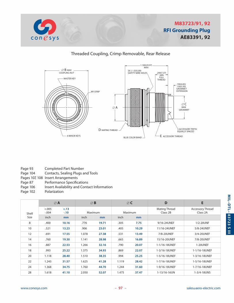
97www.conesys.com [email protected]
MIL–D
TL–
83723 S III
M83723/91, 92RFI Grounding Plug
AE83391, 92
Threaded Coupling, Crimp Removable, Rear Release
– –
Page 93 Completed Part NumberPage 104 Contacts, Sealing Plugs and ToolsPages 107, 108 Insert ArrangementsPage 87 Performance SpecificationsPage 106 Insert Availability and Contact InformationPage 102 Polarization
4 MINOR KEYS
MASTER KEY
BLUE COLOR BAND
1.180(29.97)MAX
RFI STRIP
[ B MAXCOUPLING NUT
[ CMAX
GROMMET[ A
D MATING THREAD
E ACCESSORY THREAD
3 ACCESSORY TEETHEQUALLY SPACED
3X [ .035(.89)SAFETY WIRE HOLES .290(7.37)
MINFULL
THREAD
.190(4.83)
.130(3.30)GROMMETEXTENSION
ShellSize
� A � B � C D E
+.005 +.13 Mating Thread Accessory Thread-.004 -.10 Maximum Maximum Class 2B Class 2A
inch mm inch mm inch mm
8 .400 10.16 .776 19.71 .305 7.75 9/16-24UNEF 1/2-20UNF
10 .521 13.23 .906 23.01 .405 10.29 11/16-24UNEF 5/8-24UNEF
12 .691 17.55 1.078 27.38 .531 13.49 7/8-20UNEF 3/4-20UNEF
14 .760 19.30 1.141 28.98 .665 16.89 15/16-20UNEF 7/8-20UNEF
16 .887 22.53 1.266 32.16 .790 20.07 1-1/16-18UNEF 1-20UNEF
18 .993 25.22 1.375 34.93 .869 22.07 1-3/16-18UNEF 1-1/16-18UNEF
20 1.118 28.40 1.510 38.35 .994 25.25 1-5/16-18UNEF 1-3/16-18UNEF
22 1.243 31.57 1.625 41.28 1.119 28.42 1-7/16-18UNEF 1-5/16-18UNEF
24 1.368 34.75 1.760 44.70 1.244 31.60 1-9/16-18UNEF 1-7/16-18UNEF
28 1.618 41.10 2.050 52.07 1.475 37.47 1-13/16-16UN 1-3/4-18UNS

98www.conesys.com [email protected]
MIL–D
TL–
83723 S III
M83723/95, 96Self-Locking PlugAE83395, 96
Threaded Coupling, Crimp Removable, Rear Release
– –
Page 93 Completed Part NumberPage 104 Contacts, Sealing Plugs and ToolsPages 107, 108 Insert ArrangementsPage 87 Performance SpecificationsPage 106 Insert Availability and Contact InformationPage 102 Polarization
BLUE COLOR BAND
1.180(29.97)MAX
[ C MAXCOUPLING NUT
D MATING THREAD
[ A
E ACCESSORY THREAD
3 ACCESSORY TEETHEQUALLY SPACED
[ BMAX
GROMMET
.190(4.83)
.130(3.30)GROMMETEXTENSION
.290(7.37) MINFULL
THREAD
4 MINOR KEYS
MASTER KEY
ShellSize
� A � B � C D E+.005 +.13 Mating Thread Accessory Thread-.004 -.10 Maximum Maximum Class 2B Class 2A
inch mm inch mm inch mm
8 .400 10.16 .305 7.75 .832 21.13 9/16-24UNEF 1/2-20UNF
10 .521 13.23 .405 10.29 .959 24.36 11/16-24UNEF 5/8-24UNEF
12 .691 17.55 .531 13.49 1.097 27.86 7/8-20UNEF 3/4-20UNEF
14 .760 19.30 .665 16.89 1.236 31.39 15/16-20UNEF 7/8-20UNEF
16 .887 22.53 .790 20.07 1.360 34.54 1-1/16-18UNEF 1-20UNEF
18 .993 25.22 .869 22.07 1.473 37.41 1-3/16-18UNEF 1-1/16-18UNEF
20 1.118 28.40 .994 25.25 1.586 40.28 1-5/16-18UNEF 1-3/16-18UNEF
22 1.243 31.57 1.119 28.42 1.703 43.26 1-7/16-18UNEF 1-5/16-18UNEF
24 1.368 34.75 1.244 31.60 1.846 46.89 1-9/16-18UNEF 1-7/16-18UNEF
28 1.618 41.10 1.475 37.47 2.278 57.86 1-13/16-16UN 1-3/4-18UNS

99www.conesys.com [email protected]
MIL–D
TL–
83723 S III
M83723/97, 98Self-Locking, RFI Grounding Plug
AE83397, 98
Threaded Coupling, Crimp Removable, Rear Release
– –
Page 93 Completed Part NumberPage 104 Contacts, Sealing Plugs and ToolsPages 107, 108 Insert ArrangementsPage 87 Performance SpecificationsPage 106 Insert Availability and Contact InformationPage 102 Polarization
.160(4.06)
.010(0.25)GROMMETEXTENSION
4 MINOR KEYS
BLUE COLOR BAND
F ACCESSORY THREAD
BNUMBER OF TEETH
1.280(32.51)MAX
MASTER KEY
RFI STRIP
[ D MAXCOUPLING NUT
E MATING THREAD
[ A[ CMAX
GROMMET
.290(7.37) MINFULL
THREAD
ShellSize
� A B � C � D E F
+.005 +.13 No. of Mating Thread Accessory Thread-.004 -.10 Teeth Maximum Maximum Class 2B Class 2A
inch mm inch mm inch mm
8 .400 10.16 12 .305 7.75 .967 24.56 9/16-24UNEF 1/2-20UNF
10 .521 13.23 15 .405 10.29 1.093 27.76 11/16-24UNEF 5/8-24UNEF
12 .691 17.55 21 .531 13.49 1.170 29.72 7/8-20UNEF 3/4-20UNEF
14 .760 19.30 24 .665 16.89 1.310 33.27 15/16-20UNEF 7/8-20UNEF
16 .887 22.53 30 .790 20.07 1.500 38.10 1-1/16-18UNEF 1-20UNEF
18 .993 25.22 33 .869 22.07 1.562 39.67 1-3/16-18UNEF 1-1/16-18UNEF
20 1.118 28.40 36 .994 25.25 1.710 43.43 1-5/16-18UNEF 1-3/16-18UNEF
22 1.243 31.57 39 1.119 28.42 1.812 46.02 1-7/16-18UNEF 1-5/16-18UNEF
24 1.368 34.75 42 1.244 31.60 1.948 49.48 1-9/16-18UNEF 1-7/16-18UNEF
28 1.618 41.10 54 1.475 37.47 2.278 57.86 1-13/16-16UN 1-3/4-18UNS

100www.conesys.com [email protected]
MIL–D
TL–
83723 S III
M83723/68, 69Lanyard Release, Quick-Disconnect PlugAE83368, 69
Quick-Disconnect, Threaded Coupling, Crimp Removable, Rear Release
– –
Page 93 Completed Part NumberPage 104 Contacts, Sealing Plugs and ToolsPages 107, 108 Insert ArrangementsPage 87 Performance SpecificationsPage 106 Insert Availability and Contact InformationPage 102 Polarization
Note 1:M83723/70 receptacle adapter (page 101) is requiredto mate the Quick-Disconnect Plug with a receptacle.
Note 2: Not available in shell size 8.
C ACCESSORY THREAD
7.500(190.50)MAX
[ AMAX
[ D
MASTERKEY
1.180(29.97)MAX
.190(4.83)
.130(3.30) GROMMET EXTENSION
BLUE COLOR BAND
[ B MAX GROMMET
3 ACCESSORY TEETHEQUALLY SPACED
LENGTH TO BE MEASURED WITH A[ .750(19.05)±.060(1.52) BAR TO PULLLANYARD TAUT
4 MINOR KEYS
ShellSize
� A � B C � D
Accessory ThreadMaximum Maximum Class 2A
inch mm inch mm inch mm
10 1.240 31.50 .405 10.29 5/8-24UNEF .526/.517 13.36/13.13
12 1.432 36.37 .531 13.49 3/4-20UNEF .696/.687 17.68/17.45
14 1.490 37.85 .665 16.89 7/8-20UNEF .765/.756 19.43/19.20
16 1.711 43.46 .790 20.07 1-20UNEF .892/.883 22.66/22.43
18 1.815 46.10 .869 22.07 1-1/16-18UNEF .998/.989 25.35/25.12
20 1.962 49.83 .994 25.25 1-3/16-18UNEF 1.123/1.114 28.52/28.30
22 2.070 52.58 1.119 28.42 1-5/16-18UNEF 1.248/1.239 31.70/31.47
24 2.195 55.75 1.244 31.60 1-7/16-18UNEF 1.373/1.364 34.87/34.65
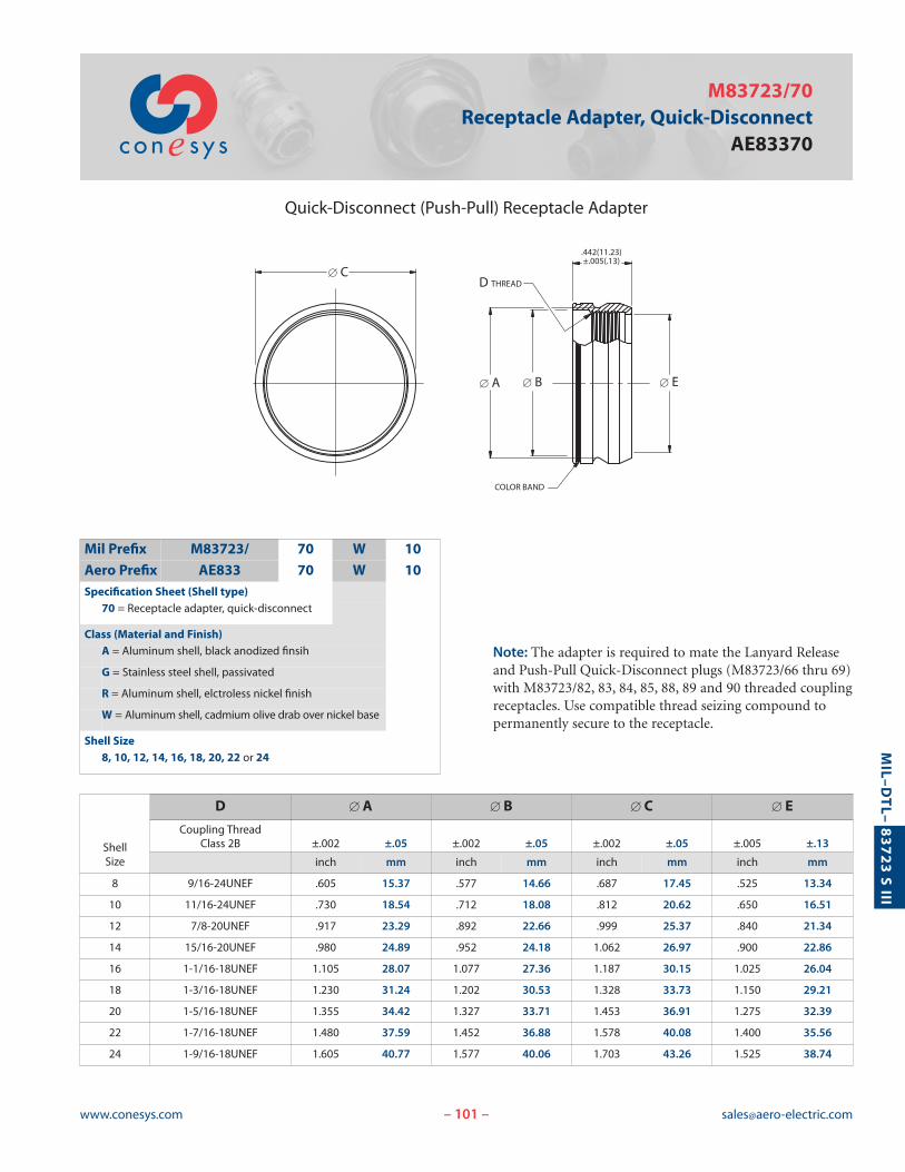
101www.conesys.com [email protected]
MIL–D
TL–
83723 S III
M83723/70Receptacle Adapter, Quick-Disconnect
AE83370
Quick-Disconnect (Push-Pull) Receptacle Adapter
– –
COLOR BAND
D THREAD
[ B[ A
[ C
[ E
.442(11.23)±.005(.13)
Note: The adapter is required to mate the Lanyard Releaseand Push-Pull Quick-Disconnect plugs (M83723/66 thru 69)with M83723/82, 83, 84, 85, 88, 89 and 90 threaded couplingreceptacles. Use compatible thread seizing compound topermanently secure to the receptacle.
ShellSize
D � A � B � C � E
Coupling ThreadClass 2B ±.002 ±.05 ±.002 ±.05 ±.002 ±.05 ±.005 ±.13
inch mm inch mm inch mm inch mm
8 9/16-24UNEF .605 15.37 .577 14.66 .687 17.45 .525 13.34
10 11/16-24UNEF .730 18.54 .712 18.08 .812 20.62 .650 16.51
12 7/8-20UNEF .917 23.29 .892 22.66 .999 25.37 .840 21.34
14 15/16-20UNEF .980 24.89 .952 24.18 1.062 26.97 .900 22.86
16 1-1/16-18UNEF 1.105 28.07 1.077 27.36 1.187 30.15 1.025 26.04
18 1-3/16-18UNEF 1.230 31.24 1.202 30.53 1.328 33.73 1.150 29.21
20 1-5/16-18UNEF 1.355 34.42 1.327 33.71 1.453 36.91 1.275 32.39
22 1-7/16-18UNEF 1.480 37.59 1.452 36.88 1.578 40.08 1.400 35.56
24 1-9/16-18UNEF 1.605 40.77 1.577 40.06 1.703 43.26 1.525 38.74
Mil Prefix M83723/ 70 W 10
Aero Prefix AE833 70 W 10Specification Sheet (Shell type)
70 = Receptacle adapter, quick-disconnect
Class (Material and Finish)A = Aluminum shell, black anodized finsih
G = Stainless steel shell, passivated
R = Aluminum shell, elctroless nickel finish
W = Aluminum shell, cadmium olive drab over nickel base
Shell Size8, 10, 12, 14, 16, 18, 20, 22 or 24

102www.conesys.com [email protected]
MIL–D
TL–
83723 S III
MIL-DTL-83723 Series IIIPolarization (Shell Keying, Insert Clocking)Bayonet and Threaded
Shell Keying Insert Clocking
– –
Notes:1. In the normal position (N), the insert centerline coin-
cides with the centerline of the master keyway (key) ofthe shell. E = 0°.
2. In the alternate keying positions (6, 7, 8, 9 and Y), theminor keyways (keys) are positioned with reference tomaster keyway (key) as indicated in the keying positiontable below.
3. In the alternate insert clocking positions (1, 2, 3, 4 and5), the pin insert (viewing from the mating side) isrotated counter-clockwise relative to the centerline of themaster keyway (key) of the shell. The socket insert isrotated clockwise.
* Per MIL-STD-1554, keyed position Y and clocked positions 1, 2, 3, 4and 5 are not available in shell size 8.
** Shell size 28 is not from military standard. It is only availabe inthreaded family to Aero-Electric part number.
† Per MIL-STD-1554, insert positions 1 thru 5 are inactive for newdesign.
Note: Alternate positions “Z” and “10” are cancelled andsuperseded by Position “Y”.
ShellSize
Polarizing Key/Keyway Positions Insert Position
Position A° B° C° D° E°
8*, 10
N 105 140 215 265 0
6 102 132 248 320 0
7 80 118 230 312 0
8 35 140 205 275 0
9 64 155 234 304 0
10 only Y 25 115 220 270 0
12 thru 24, 28**
N 105 140 215 265 0
6 18 149 192 259 0
7 92 152 222 342 0
8 84 152 204 334 0
9 24 135 189 240 0
Y 98 152 268 338 0
10 thru 24
1† 105 140 215 265 10
2† 105 140 215 265 20
3† 105 140 215 265 30
4† 105 140 215 265 40
5† 105 140 215 265 50
INSERTVERTICALCENTERLINE
PIN INSERTMATING FACE
(SOCKET INSERT IS OPPOSITE)
ENGAGING FACE VIEW FOR RECEPTACLE SHELL KEYWAYS (PLUG SHELL KEYS, OPPOSITE)
MASTERKEYWAY(KEY)OF SHELL
E°
C°
B°
D°
A°
MASTERKEYWAY

103www.conesys.com [email protected]
MIL–D
TL–
83723 S III
MIL-DTL-83723 Series III, Bayonet and ThreadedFlange and Jam Nut Receptacles
Panel Cutouts
Panel Cutouts
– –
L
[ LL[ J
S
[ Z
Flange and Jam Nut Mounting Dimensions
Panel Thickness
* Includes screw-head
Receptacle Type Rear Mounting Front Mountinginch mm inch mm
Wall Mount Receptacle, Bayonet .250 max* 6.36 max* .125 max 3.18 max
Wall Mount Receptacle, Threaded .125 max 3.18 max .125 max 3.18 max
Jam Nut Mount (Bayonet & Threaded) .062/.125 1.57/3.18 — —
ShellSize
L � J � J � LL S � Z
For Back Mounting For Front Mounting +.000 +.00(TP) Minimum Minimum -.009 -.23 ±.005 ±.13 ±.005 ±.13
inch mm inch mm inch mm inch mm inch mm inch mm
8 .594 15.09 .620 15.75 .510 12.95 .125 3.18 .605 15.37 .635 16.13
10 .719 18.26 .748 19.00 .635 16.13 .125 3.18 .730 18.54 .760 19.30
12 .812 20.62 .918 23.32 .760 19.30 .125 3.18 .917 23.29 .947 24.05
14 .906 23.01 .988 25.10 .885 22.48 .125 3.18 .980 24.89 1.010 25.65
16 .969 24.61 1.114 28.30 1.010 25.65 .125 3.18 1.105 28.07 1.135 28.83
18 1.062 26.97 1.220 30.99 1.072 27.23 .125 3.18 1.229 31.22 1.260 32.00
20 1.156 29.36 1.346 34.19 1.197 30.40 .125 3.18 1.354 34.39 1.385 35.18
22 1.250 31.75 1.470 37.34 1.322 33.58 .125 3.18 1.479 37.57 1.510 38.35
24 1.375 34.93 1.596 40.54 1.442 36.63 .154 3.91 1.604 40.74 1.635 41.53

104www.conesys.com [email protected]
MIL–D
TL–
83723 S III
MIL-DTL-83723Contacts, Tools and Seal PlugsSeries III
Contacts, Plastic Insertion/Removal Tools and Seal Plugs
Crimping and Metal Insertion/Extraction Tools
Contact and Wire Data
– –
Note: Test Current and Maximum Voltage Drop whentested with silver-plated wire at 25°C.
ContactSize
Application Pin Contacts Socket Contacts Seal Plugs Insertion/Removal Tools
Plastic
Type Military No. Military No. Military No. Military No.
20 Power/Signal M39029/4-110 M39029/5-115 MS27488-20-1 M81969/14-11
16 Power/Signal M39029/4-111 M39029/5-116 MS27488-16-1 M81969/14-03
12 Power/Signal M39029/4-113 M39029/5-118 MS27488-12-1 M81969/14-04
ContactSize
Crimp Tool Positioner Positioner Insertion Tool Extraction Tool
For Pin Contacts For Socket Contacts Metal Metal
Military No. Military No. Military No. Military No. Military No.
20M22520/1-01 M22520/1-02 M22520/1-02
M81969/8-205 M81969/8-206M22520/2-01 M22520/2-02 M22520/2-02
16 M22520/1-01 M22520/1-02 M22520/1-02 M81969/8-207 M81969/8-208
12 M22520/1-01 M22520/1-02 M22520/1-02 M81969/8-209 M81969/8-210
ContactSize
Test Current Voltage Crimp Well Data Wire Range Finished Wire � Range
DC Test Max. Drop Well Dia. Minimum Well Dept Minimum Maximum
Amps Millivolts inch inch mm AWG mm2 inch mm inch mm
20 7.5 55 .049 ±.001 .155 3.94 24-20 .20-.52 .040 1.02 .083 2.11
16 13.0 49 .067 ±.001 .250 6.35 20-16 .52-1.31 .053 1.35 .103 2.62
12 23.0 42 .100 ±.002 .250 6.35 14-12 2.08-3.31 .097 2.46 .158 4.01

105www.conesys.com [email protected]
MIL–D
TL–
83723 S III
MIL-DTL-83723 Series IIIContact Installation InstructionsBayonet and Threaded Coupling
– –
Contact InstallationInstructions
Crimping Contacts 1. Select the appropriate crimp tool and ensure that the
proper crimp head positioner is used.
2. Cycle the tool to be sure the indentors are open.
3. Determine the correct selector setting for the wire sizefrom the data plate on the positioner (turret head assembly) and set the selector knob on the crimp tool to match.
4. Place the contact, mating end first, into the tool.
5. Insert the stripped wire into the hollow end of the contact.Be sure the wire is inserted as far as it will go.
6. Close the tool completely to crimp. Unless the tool isclosed completely, the tool will not release the contact.
7. Remove the crimped contact from the tool. Check theinspection hole to verify that the wire is fully inserted.
Insertion of Contacts1. Before inserting the contacts, unscrew the accessories
(clamps, backshells or adapters) from rear of plug orreceptacle. Slide the hardware over the wire bundle in the proper order for reassembly after all the contacts are inserted.
2. To assist insertion of contacts, lubricate insulator (grommet) cavities with isopropyl alcohol. Alcohol willevaporate and will not leave a conductive film. Caution:Never use any lubricant other than isopropyl alcohol.
3. Place the correct insertion tool on the contact so that thewire runs along the groove in the tool. (Tool tip will buttagainst the shoulder.) Hold the plug or receptacle bodyfirmly.
4. Beginning with a center cavity, insert the contact into theinsulator with a slow, even pressure until the contactsnaps into position. Make sure the contact and tool areheld perpendicular to the face of the insert during thecontact installation or the grommet could be damaged.
4.1 If contacts are not inserted all the way prior toremoving insertion tool, do not try to reinsert theinsertion tool. Instead, remove the contact and tryagain; otherwise reinserting the insertion tool maydamage the inside of the contact cavity.
5. Remove tool and check the face of the connector forproper contact installation. Proper installation may alsobe checked by pulling back lightly on the wire to makesure the contact is properly seated.
CompletionAfter all the cavities have been filled, slide the hardware backinto position on the connector and tighten.
Extraction of Contacts (Rework)1. Slide the hardware back over the wire bundle.
2. Select the appropriate tool. Place the wire into theextraction tool of the pin or socket.
3. Slowly slide the extraction tool down wire into the contact cavities until the tool tip bottoms against thecontact shoulder, expanding the clip retaining tines. Holdthe wire firmly in the tool and pull the wired contact andtool straight out of the rear of the insulator.
Size Pin Contact Socket Contact Basic Crimp Tool Pin Positioner Socket Positioner Insertion/Removal Tool
20 M39029/4-110 M39029/5-115M22520/1-01 M22520/1-02 Red M22520/1-02 Red
M81969/14-11M22520/2-01 M22520/2-02 M22520/2-02
16 M39029/4-111 M39029/5-116 M22520/1-01 M22520/1-02 Blue M22520/1-02 Blue M81969/14-03
12 M39029/4-113 M39029/5-118 M22520/1-01 M22520/1-02 Yellow M22520/1-02 Yellow M81969/14-04
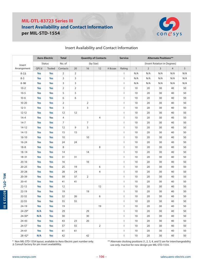
106www.conesys.com [email protected]
MIL–D
TL–
83723 S III
MIL-DTL-83723 Series IIIInsert Availability and Contact Informationper MIL-STD-1554
Insert Availability and Contact Information
– –
* Non MIL-STD-1554 layout, available to Aero-Electric part number only.� Consult factory for pin insert availablility.
** Alternate clocking positions (1, 2, 3, 4, and 5) are for interchangeabilityuse only. Inactive for new design per MIL-STD-1554.
InsertArrangement
Aero-Electric Total Quantity of Contacts Service Alternate Positions**
Status No. of (by Size) (Insert Rotation in Degrees)
QPL'd Tooled Contacts 20 16 12 # 8coax Rating 1 2 3 4 5
8-2� Yes Yes 2 2 I N/A N/A N/A N/A N/A
8-3 Yes Yes 3 3 I N/A N/A N/A N/A N/A
8-98 Yes Yes 3 3 I N/A N/A N/A N/A N/A
10-2 Yes Yes 2 2 I 10 20 30 40 50
10-5 Yes Yes 5 5 I 10 20 30 40 50
10-6 Yes Yes 6 6 I 10 20 30 40 50
10-20 Yes Yes 2 2 I 10 20 30 40 50
12-3 Yes Yes 3 3 I 10 20 30 40 50
12-12 Yes Yes 12 12 I 10 20 30 40 50
14-4 Yes Yes 4 4 I 10 20 30 40 50
14-7 Yes Yes 7 7 I 10 20 30 40 50
14-12 Yes Yes 12 9 3 I 10 20 30 40 50
14-15 Yes Yes 15 15 I 10 20 30 40 50
16-10 Yes Yes 10 10 I 10 20 30 40 50
16-24 Yes Yes 24 24 I 10 20 30 40 50
18-8 Yes Yes 8 8 I 10 20 30 40 50
18-14 Yes Yes 14 14 I 10 20 30 40 50
18-31 Yes Yes 31 31 I 10 20 30 40 50
20-16 Yes Yes 16 16 I 10 20 30 40 50
20-25 Yes Yes 25 19 6 I 10 20 30 40 50
20-28 Yes Yes 28 24 4 I 10 20 30 40 50
20-39 Yes Yes 39 37 2 I 10 20 30 40 50
20-41 Yes Yes 41 41 I 10 20 30 40 50
22-12 Yes Yes 12 12 I 10 20 30 40 50
22-19 Yes Yes 19 19 I 10 20 30 40 50
22-32 Yes Yes 32 26 6 I 10 20 30 40 50
22-55 Yes Yes 55 55 I 10 20 30 40 50
24-19 Yes Yes 19 19 I 10 20 30 40 50
24-29* N/A Yes 29 29 I 10 20 30 40 50
24-30* N/A Yes 30 30 I 10 20 30 40 50
24-43 Yes Yes 43 23 20 I 10 20 30 40 50
24-57 Yes Yes 57 55 2 I 10 20 30 40 50
24-61 Yes Yes 61 61 I 10 20 30 40 50
28-42* N/A Yes 42 42 I 10 20 30 40 50

2
13
2
11
2
12
3 4
5
6
21
802*2 # 20
I
8033 # 20
I
8983 # 20
I
10022 # 20
I
10055 # 20
I
10066 # 20
I
10202 # 16
I
12033 # 16
I
121212 # 20
I
14044 # 12
I
14077 # 16
I
14129 # 20, 3 # 16
I
181414 # 16
I
183131 # 20
I
201616 # 16
I
202519 # 20, 6 # 12
I
202824 # 20, 4 # 12
I
203937 # 20, 2 # 16
I
204141 # 20
I
221212 # 12
I
1
31
1
25
1
3
1
5
1
2 3
1
4
1
7
18088 # 12
I
1
8
1
12
1
12
141515 # 20
I
1
15
161010 # 16
I
1
10
1
14
1
12
1
39
162424 # 20
I
1
24
1
16
1
28
1
41
107www.conesys.com [email protected]
MIL–D
TL–
83723 S III
MIL-STD-1554Insert Arrangements (Socket Front View)for MIL-DTL-83723 Series III Connectors
Insert Arrangement Views
– –
* Consult factory for pin insert availability.
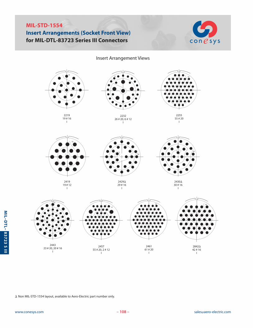
108www.conesys.com [email protected]
MIL–D
TL–
83723 S III
MIL-STD-1554Insert Arrangements (Socket Front View)for MIL-DTL-83723 Series III Connectors
Insert Arrangement Views
– –
221919 # 16
I
241919 # 12
I
223226 # 20, 6 # 12
I
244323 # 20, 20 # 16
I
2430D30 # 16
I
2429D29 # 16
I
225555 # 20
I
245755 # 20, 2 # 12
I
246161 # 20
I
2842D42 # 16
I
19
1 1
32
1
43
291
1 30
1
55
1
61
1
57
1
42
1
19
� Non MIL-STD-1554 layout, available to Aero-Electric part number only.

109www.conesys.com [email protected]
MIL–D
TL–
26500
MIL-DTL-26500Features and Application
MS2426*/AE66*
– –109www.conesys.com [email protected]
Connector Sealing – A pressure seal at the connector interface is accomplished through the aid of a couplingdevice which compresses the front resilient insulators andthus offers a seal around each contact preventing the passage of moisture through the contact cavity. Rear resilientinsulators are designed with a triple wire seal in each cavityto offer positive sealing and prevent wicking of moisturethrough the connector without the use of external clampingdevices or adapters. In addition, a dynamic O’ring seal inthe receptacles engages the front of the plug shell when connectors are mated and offers yet another barrier tomoisture and contaminants.
Superior Contact Stability - Front release crimp contactsystem features a beryllium-copper retaining clip completelyencased in a tough dielectric wafer, thus protecting the cliptines from damage.
Closed Entry Socket ContactsClosed-entry socket contacts facilitate positive mating.
Features and Application
MIL-DTL-26500 family offers connectors with bayonet coupling as well as threaded coupling. These connectors areintermateable with correspondingly coupled MIL-DTL-83723Series III connectors (except shell size 8, threaded couplingonly).
AE66 connectors are widely used on commercial, militaryand aerospace systems requiring general-purpose, miniaturecylindrical bayonet or threaded coupling connectors.
This family (bayonet as well as threaded) of connectors is offered in wall mount receptacles, jam nut mountedreceptacles which incorporate O’ring seals, designed for rear panel “D” hole mounting, and straight plugs.
Twenty-one insert arrangements per MIL-STD-1554 aretooled and qualified to MIL-DTL-26500, utilizing 3 to 57M39029 contacts. Contacts come in sizes 20, 16 and 12, terminating wire sizes from 24 to 12 gauge.
These connectors are only available in aluminum shells with anodic plating to the MS number. In addition, we offer connectors with passivated stainless steel shells to commercialcallouts only.
Insert PolarizationAlternate insert positions documented in the original specification, positions 1 through 5, are still available(except in shell size 8), but are not approved for new design.These alternate insert clocking positions aid in mating ofadjacent connectors having identical insert arrangement.
Shell Polarization – Alternate key/keyway positions preventcross mating of adjacent connectors having same insertarrangement.

110www.conesys.com [email protected]
MIL–D
TL–
26500
MIL-DTL-26500Performance SpecificationsMS2426*/AE66*
– –
Performance Specifications
Operating Temperature RangeClass R: -55°C to +200°C (-67°F to +392°F)Class E*: -55°C to +200°C (-67°F to +392°F)
Material and Finish Data (Class)R – aluminum shell, black anodized finishE*– stainless steel shell, passivated
Corrosion ResistanceClasses R and E* withstand 48-hour salt spray.
Environmental SealWired, mated connectors shall meet the altitude-immersiontest specified by MIL-DTL-26500.
Fluid ResistanceUnmated connectors resist specified immersions in MIL-PRF-5606 (hydraulic fluid), MIL-PRF-23699 (lubricatingoil), MIL-PRF-7808 (lubricating oil), MIL-DTL-5624 (JP-5)and glycol.
DurabilityBayonet Coupling – 500 cyclesThreaded Coupling – 200 cycles
Voltage Rating
Shock and Vibration RequirementsWired, mated connectors shall not be damaged, couplingring shall not loosen, and there shall be no interruption ofelectrical continuity longer than one microsecond whensubjected to the following:
ShockMated connectors withstand a pulse of approximate half sine wave of 100 G magnitude with duration of 6 milliseconds applied in each of the three major axes.
VibrationMated connectors withstand the following vibration levels:� Vibration per EIA-364, test procedure 28 conducted at a
low temperature ambient of -55°C (-67°F) and highambient of +200°C (392°F).
Shell-to-Shell Conductivity� Class R is non-conductive.� Maximum potential drop shall not exceed 200 millivolts
for class E*.
* Class E only available to commercial callouts. Consult factory for drawings. Pages 112 thru 117 apply to class R only.
** To be used by designer only as a guide.
ServiceRating
Suggested Operating Voltage** Test Voltage Test Voltage Test Voltage Test Voltage
(Sea Level) Sea Level 50,000 Ft. 70,000 Ft. 110,000 Ft.
AC (RMS) DC V RMS V RMS V RMS V RMS
I 600 850 1500 450 275 200

111www.conesys.com [email protected]
MIL–D
TL–
26500
MIL-DTL-26500Part Number Development
Bayonet & Threaded Coupling
– –
Part Number Development
Note 1: Each connector is furnished with contacts unlessordered less contacts (L/C) as follows: Two spare contactsfor each size contact utilized and at least 15% of the numberof contacts but no less than three sealing plugs are provided.No insertion/removal tools are provided. No spares arerequired for shielded contacts.
Note 2: Proper part number marking has no “0” in front ofsingle digit shell size (8), and no “0” in front of single digitlayouts. Example: MS24264R8B3SN and MS24264R18B8P6.Please note that in this series “N” for normal is included inpart number marking.
Mil. Prefix MS 24266 R 12 T 12 P N
Aero Prefix AE 666 R 12 T 12 P N -340Shell type
24264 = Wall mount receptacle = 664 (Aero p/n)
24265 = Jam nut receptacle = 665 (Aero p/n)
24266 = Straight plug = 666 (Aero p/n)
Class (Material and Finish)R = Aluminum shell, black anodized finish
E* = Stainless steel shell, passivated
Shell Size (SS)8, 10, 12, 14, 16, 18, 20, 22 or 24
Coupling MechanismB = Bayonet Coupling
T = Threaded Coupling
Insert ArrangementSee pages 122, 123
Contact StyleP = Pin
S = Socket
Polarization (Keying)N = Normal
6, 7, 8, 9 or Y (Alternate keyed positions, Y is not availabe in SS 8)
1, 2, 3, 4 or 5 (Clocked insert polarizations within normally keyed shell, not approved for new design, n/a in SS 8)
Modification (applies to Aero part numbers only)01 = Less contacts (is not marked on the part)
341 = Connector kitted with MS27291-XX straight clamp
Consult factory for other modifications
* Class E only available to commercial callouts. Consult factory for drawings. Pages 112 thru 117 apply to class R only.
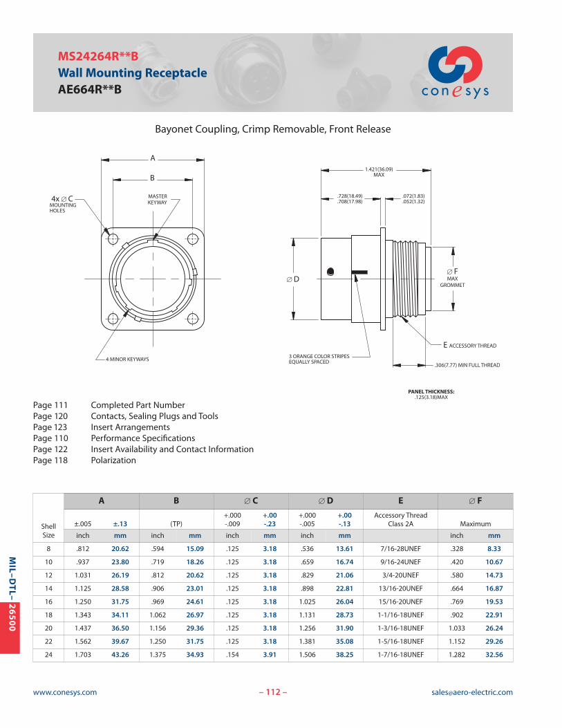
1.421(36.09)MAX
4x [ CMOUNTING HOLES
3 ORANGE COLOR STRIPESEQUALLY SPACED
PANEL THICKNESS:.125(3.18)MAX
[ D
KEYWAYMASTER
B
.728(18.49)
.708(17.98)
A
E ACCESSORY THREAD
[ FMAX
GROMMET
.072(1.83)
.052(1.32)
.306(7.77) MIN FULL THREAD4 MINOR KEYWAYS
112www.conesys.com [email protected]
MIL–D
TL–
26500
MS24264R**BWall Mounting ReceptacleAE664R**B
Bayonet Coupling, Crimp Removable, Front Release
– –
Page 111 Completed Part NumberPage 120 Contacts, Sealing Plugs and ToolsPage 123 Insert ArrangementsPage 110 Performance SpecificationsPage 122 Insert Availability and Contact InformationPage 118 Polarization
ShellSize
A B � C � D E � F
+.000 +.00 +.000 +.00 Accessory Thread±.005 ±.13 (TP) -.009 -.23 -.005 -.13 Class 2A Maximum
inch mm inch mm inch mm inch mm inch mm
8 .812 20.62 .594 15.09 .125 3.18 .536 13.61 7/16-28UNEF .328 8.33
10 .937 23.80 .719 18.26 .125 3.18 .659 16.74 9/16-24UNEF .420 10.67
12 1.031 26.19 .812 20.62 .125 3.18 .829 21.06 3/4-20UNEF .580 14.73
14 1.125 28.58 .906 23.01 .125 3.18 .898 22.81 13/16-20UNEF .664 16.87
16 1.250 31.75 .969 24.61 .125 3.18 1.025 26.04 15/16-20UNEF .769 19.53
18 1.343 34.11 1.062 26.97 .125 3.18 1.131 28.73 1-1/16-18UNEF .902 22.91
20 1.437 36.50 1.156 29.36 .125 3.18 1.256 31.90 1-3/16-18UNEF 1.033 26.24
22 1.562 39.67 1.250 31.75 .125 3.18 1.381 35.08 1-5/16-18UNEF 1.152 29.26
24 1.703 43.26 1.375 34.93 .154 3.91 1.506 38.25 1-7/16-18UNEF 1.282 32.56

MOUNTING FLAT
3 ORANGE COLOR STRIPESEQUALLY SPACED E ACCESSORY THREAD
JAM-NUT THREADG
HEX NUT WITH3 TEFLON PLUGSEQUALLY SPACED
"O" RING
PANEL THICKNESS: .125(3.18) MAX
[ FMAX
GROMMET[ D
.781(19.84)
.761(19.33)
1.421(36.09) MAX
.306(7.77)MIN FULL THREAD
[ AMAX
B
CMASTERKEYWAY
113www.conesys.com [email protected]
MIL–D
TL–
26500
MS24265R**BJam Nut Receptacle
AE665R**B
Bayonet Coupling, Crimp Removable, Front Release
– –
Page 111 Completed Part NumberPage 120 Contacts, Sealing Plugs and ToolsPage 123 Insert ArrangementsPage 110 Performance SpecificationsPage 122 Insert Availability and Contact InformationPage 118 Polarization
ShellSize
� A B C � D E � F G
+.000 +.00 Accessory Thread Jam Nut ThreadMaximum ±.005 ±.13 ±.003 ±.08 -.005 -.13 Class 2A Maximum Class 2A
inch mm inch mm inch mm inch mm inch mm
8 1.068 27.13 .979 24.87 .593 15.06 .536 13.61 7/16-28UNEF .328 8.33 5/8-20UN
10 1.192 30.28 1.104 28.04 .718 18.24 .659 16.74 9/16-24UNEF .420 10.67 3/4-20UNEF
12 1.380 35.05 1.291 32.79 .905 22.99 .829 21.06 3/4-20UNEF .580 14.73 15/16-20UNEF
14 1.505 38.23 1.391 35.33 .968 24.59 .898 22.81 13/16-20UNEF .664 16.87 1-20UNEF
16 1.630 41.40 1.516 38.51 1.093 27.76 1.025 26.04 15/16-20UNEF .769 19.53 1-1/8-20UN
18 1.740 44.20 1.641 41.68 1.217 30.91 1.131 28.73 1-1/16-18UNEF .902 22.91 1-1/4-20UN
20 1.860 47.24 1.766 44.86 1.342 34.09 1.256 31.90 1-3/16-18UNEF 1.033 26.24 1-3/8-18UNEF
22 2.040 51.82 1.954 49.63 1.467 37.26 1.381 35.08 1-5/16-18UNEF 1.152 29.26 1-1/2-20UN
24 2.160 54.86 2.079 52.81 1.592 40.44 1.506 38.25 1-7/16-18UNEF 1.282 32.56 1-5/8-18UNEF

114www.conesys.com [email protected]
MIL–D
TL–
26500
MS24266R**BStraight PlugAE666R**B
Bayonet Coupling, Crimp Removable, Front Release
– –
Page 111 Completed Part NumberPage 120 Contacts, Sealing Plugs and ToolsPage 123 Insert ArrangementsPage 110 Performance SpecificationsPage 122 Insert Availability and Contact InformationPage 118 Polarization
D ACCESSORY THREAD
3 ORANGE STRIPESEQUALLY SPACED
.306(7.77) MIN FULL THREAD
[ B[ CMAX
GROMMET
[ AMAX COUPLING NUT 1.375(34.93)
MAX
4 MINOR KEYS
MASTER KEY
ShellSize
� A � B � C D
+.000 +.00 Accessory ThreadMaximum -.005 -.13 Maximum Class 2A
inch mm inch mm inch mm
8 .776 19.71 .424 10.77 .328 8.33 7/16-28UNEF
10 .906 23.01 .526 13.36 .420 10.67 9/16-24UNEF
12 1.078 27.38 .696 17.68 .580 14.73 3/4-20UNEF
14 1.141 28.98 .765 19.43 .664 16.87 13/16-20UNEF
16 1.266 32.16 .892 22.66 .769 19.53 15/16-20UNEF
18 1.375 34.93 .998 25.35 .902 22.91 1-1/16-18UNEF
20 1.510 38.35 1.123 28.52 1.033 26.24 1-3/16-18UNEF
22 1.625 41.28 1.248 31.70 1.152 29.26 1-5/16-18UNEF
24 1.760 44.70 1.373 34.87 1.282 32.56 1-7/16-18UNEF

FULL MATE INDICATORCOLOR: ORANGE
4x [ CMOUNTINGHOLES
D MATING THREADE ACCESSORY THREAD
MASTERKEYWAY
[ FMAX
GROMMET
A
B1.421(36.09)
MAX
.728(18.49)
.708(17.98)
.306(7.77) MIN FULL THREAD
.072(1.83)
.052(1.32)
4 MINOR KEYWAYS
PANEL THICKNESS:.125(3.18) MAX
115www.conesys.com [email protected]
MIL–D
TL–
26500
MS24264R**TWall Mounting Receptacle
AE664R**T
Threaded Coupling, Crimp Removable, Front Release
– –
Page 111 Completed Part NumberPage 120 Contacts, Sealing Plugs and ToolsPage 123 Insert ArrangementsPage 110 Performance SpecificationsPage 122 Insert Availability and Contact InformationPage 118 Polarization
ShellSize
A B � C D E � F
+.000 +.00 Mating Thread Accessory Thread±.005 ±.13 (TP) -.009 -.23 Class 2A Class 2A Maximum
inch mm inch mm inch mm inch mm
8 .812 20.62 .594 15.09 .125 3.18 9/16-24UNEF 7/16-28UNEF .328 8.33
10 .937 23.80 .719 18.26 .125 3.18 11/16-24UNEF 9/16-24UNEF .420 10.67
12 1.031 26.19 .812 20.62 .125 3.18 7/8-20UNEF 3/4-20UNEF .580 14.73
14 1.125 28.58 .906 23.01 .125 3.18 15/16-20UNEF 13/16-20UNEF .664 16.87
16 1.250 31.75 .969 24.61 .125 3.18 1-1/16-18UNEF 15/16-20UNEF .769 19.53
18 1.343 34.11 1.062 26.97 .125 3.18 1-3/16-18UNEF 1-1/16-18UNEF .902 22.91
20 1.437 36.50 1.156 29.36 .125 3.18 1-5/16-18UNEF 1-3/16-18UNEF 1.033 26.24
22 1.562 39.67 1.250 31.75 .125 3.18 1-7/16-18UNEF 1-5/16-18UNEF 1.152 29.26
24 1.703 43.26 1.375 34.93 .154 3.91 1-9/16-18UNEF 1-7/16-18UNEF 1.282 32.56

E ACCESSORY THREAD
D MATING THREAD
FULL MATEINDICATORCOLOR: ORANGE
HEX NUT WITH3 TEFLON PLUGSEQUALLY SPACED
"O" RING
[ FMAX
GROMMET
G JAM-NUT THREAD
[ AMAX
B
CMOUNTING
FLAT
.306(7.77)MIN FULL THREAD
1.421(36.09) MAX
.781(19.84)
.761(19.33)
PANEL THICKNESS:.125(3.18) MAX
MASTERKEYWAY
116www.conesys.com [email protected]
MIL–D
TL–
26500
MS24265R**TJam Nut ReceptacleAE665R**T
Threaded Coupling, Crimp Removable, Front Release
– –
Page 111 Completed Part NumberPage 120 Contacts, Sealing Plugs and ToolsPage 123 Insert ArrangementsPage 110 Performance SpecificationsPage 122 Insert Availability and Contact InformationPage 118 Polarization
ShellSize
� A B C D E � F G
Mating Thread Accessory Thread Jam Nut ThreadMaximum ±.005 ±.13 ±.003 ±.08 Class 2A Class 2A Maximum Class 2A
inch mm inch mm inch mm inch mm
8 1.068 27.13 .979 24.87 .593 15.06 9/16-24UNEF 7/16-28UNEF .328 8.33 5/8-20UN
10 1.192 30.28 1.104 28.04 .718 18.24 11/16-24UNEF 9/16-24UNEF .420 10.67 3/4-20UNEF
12 1.380 35.05 1.291 32.79 .905 22.99 7/8-20UNEF 3/4-20UNEF .580 14.73 15/16-20UNEF
14 1.505 38.23 1.391 35.33 .968 24.59 15/16-20UNEF 13/16-20UNEF .664 16.87 1-20UNEF
16 1.630 41.40 1.516 38.51 1.093 27.76 1-1/16-18UNEF 15/16-20UNEF .769 19.53 1-1/8-20UN
18 1.740 44.20 1.641 41.68 1.217 30.91 1-3/16-18UNEF 1-1/16-18UNEF .902 22.91 1-1/4-20UN
20 1.860 47.24 1.766 44.86 1.342 34.09 1-5/16-18UNEF 1-3/16-18UNEF 1.033 26.24 1-3/8-18UNEF
22 2.040 51.82 1.954 49.63 1.467 37.26 1-7/16-18UNEF 1-5/16-18UNEF 1.152 29.26 1-1/2-20UN
24 2.160 54.86 2.079 52.81 1.592 40.44 1-9/16-18UNEF 1-7/16-18UNEF 1.282 32.56 1-5/8-18UNEF

117www.conesys.com [email protected]
MIL–D
TL–
26500
MS24266R**TStraight PlugAE666R**T
Threaded Coupling, Crimp Removable, Front Release
– –
Page 111 Completed Part NumberPage 120 Contacts, Sealing Plugs and ToolsPage 123 Insert ArrangementsPage 110 Performance SpecificationsPage 122 Insert Availability and Contact InformationPage 118 Polarization
1.375(34.93) MAX
[ AMAX COUPLING NUT
[ B
D ACCESSORY THREAD
[ CMAX
GROMMET
.306(7.77) MIN FULL THREAD
E MATING THREAD4 MINOR KEYS
MASTER KEY
ShellSize
� A � B � C D E
+.000 +.00 Accessory Thread Mating ThreadMaximum -.005 -.13 Maximum Class 2A Class 2B
inch mm inch mm inch mm
8 .776 19.71 .424 10.77 .328 8.33 7/16-28UNEF 9/16-24UNEF
10 .906 23.01 .526 13.36 .420 10.67 9/16-24UNEF 11/16-24UNEF
12 1.078 27.38 .696 17.68 .580 14.73 3/4-20UNEF 7/8-20UNEF
14 1.141 28.98 .765 19.43 .664 16.87 13/16-20UNEF 15/16-20UNEF
16 1.266 32.16 .892 22.66 .769 19.53 15/16-20UNEF 1-1/16-18UNEF
18 1.375 34.93 .998 25.35 .902 22.91 1-1/16-18UNEF 1-3/16-18UNEF
20 1.510 38.35 1.123 28.52 1.033 26.24 1-3/16-18UNEF 1-5/16-18UNEF
22 1.625 41.28 1.248 31.70 1.152 29.26 1-5/16-18UNEF 1-7/16-18UNEF
24 1.760 44.70 1.373 34.87 1.282 32.56 1-7/16-18UNEF 1-9/16-18UNEF

118www.conesys.com [email protected]
MIL–D
TL–
26500
MIL-DTL-26500Polarization (Shell Keying, Insert Clocking)Bayonet and Threaded
Shell Keying Insert Clocking
– –
Notes:1. In the normal position (N), the insert centerline
coincides with the centerline of the master keyway (key)of the shell: E = 0°.
2. In the alternate keying positions (6, 7, 8, 9 and Y), theminor keyways (keys) are positioned with reference tomaster key/keyway as indicated in the keying positiontable below.
3. In the alternate insert clocking positions (1, 2, 3, 4 and5), the pin insert (viewing from the mating side) isrotated counter-clockwise relative to the centerline of themaster keyway (key) of the shell. The socket insert isrotated clockwise.
* Per MIL-STD-1554, keyed position Y and clocked positions 1, 2, 3, 4 and 5are not available in shell size 8.
** Alterate positions “Z” and “10” are cancelled and superseded by Position
“Y”.† Per MIL-STD-1554, insert positions 1 thru 5 are inactive for new design.
ShellSize
Polarizing Key/Keyway Positions Insert Position
Position A° B° C° D° E°
8*, 10
N 105 140 215 265 0
6 102 132 248 320 0
7 80 118 230 312 0
8 35 140 205 275 0
9 64 155 234 304 0
10 only Y** 25 115 220 270 0
12 thru 24
N 105 140 215 265 0
6 18 149 192 259 0
7 92 152 222 342 0
8 84 152 204 334 0
9 24 135 189 240 0
Y** 98 152 268 338 0
10 thru 24
1† 105 140 215 265 10
2† 105 140 215 265 20
3† 105 140 215 265 30
4† 105 140 215 265 40
5† 105 140 215 265 50
INSERTVERTICALCENTERLINE
PIN INSERTMATING FACE
(SOCKET INSERT IS OPPOSITE)
ENGAGING FACE VIEW FORRECEPTACLE SHELL KEYWAYS(PLUG SHELL KEYS, OPPOSITE)
MASTERKEYWAY(KEY)OF SHELL
E°
C°
B°
D°
A°
MASTERKEYWAY

119www.conesys.com [email protected]
MIL–D
TL–
26500
MIL-DTL-26500 Bayonet and ThreadedFlange and Jam Nut Receptacles
Panel Cutouts
Panel Cutouts
– –
Note: Maximum panel thickness of .125 inch (3.18 mm).
Flange and Jam Nut Mounting Dimensions
L
S
[ LL[ J
[ Z
ShellSize
L � J � J � LL S � Z
For Back Mounting For Front Mounting +.000 +.00(TP) Minimum Minimum -.009 -.23 ±.005 ±.13 ±.005 ±.13
inch mm inch mm inch mm inch mm inch mm inch mm
8 .594 15.09 .620 15.75 .447 11.35 .125 3.18 .605 15.37 .635 16.13
10 .719 18.26 .748 19.00 .572 14.53 .125 3.18 .730 18.54 .760 19.30
12 .812 20.62 .913 23.19 .760 19.30 .125 3.18 .917 23.29 .947 24.05
14 .906 23.01 .980 24.89 .822 20.88 .125 3.18 .980 24.89 1.010 25.65
16 .969 24.61 1.107 28.12 .948 24.08 .125 3.18 1.105 28.07 1.135 28.83
18 1.062 26.97 1.209 30.71 1.072 27.23 .125 3.18 1.225 31.12 1.260 32.00
20 1.156 29.36 1.337 33.96 1.192 30.28 .125 3.18 1.350 34.29 1.385 35.18
22 1.250 31.75 1.452 36.88 1.322 33.58 .125 3.18 1.475 37.47 1.510 38.35
24 1.375 34.93 1.577 40.06 1.442 36.63 .154 3.91 1.600 40.64 1.635 41.53

120www.conesys.com [email protected]
MIL–D
TL–
26500
MIL-DTL-26500Contacts, Tools and Seal PlugsMS2426*/AE66*
– –
Note 1: Test Current and Maximum Voltage Drop whentested with silver-plated wire at 25°C.
Note 2: No plastic Insertion/Removal tools are supplied as partof contact packages when ordering 26500 connectors. Metalinsertion and extraction tools must be ordered separately.
Contacts, Plastic Insertion/Removal Tools and Seal Plugs
Crimping and Metal Insertion/Extraction Tools
Contact and Wire Data
ContactSize
Application Pin Contacts Socket Contacts Seal Plugs Insertion/Removal Tools
Plastic
Type Military No. Military No. Military No. Military No.
20 Power/Signal M39029/31-241 M39029/32-260 MS27488-20-1 N/A
16 Power/Signal M39029/31-229 M39029/32-248 MS27488-16-1 N/A
12 Power/Signal M39029/31-235 M39029/32-254 MS27488-12-1 N/A
8 Coax Coax M39029/54-343 M39029/55-345 MS27488-8-1 N/A
ContactSize/Type
Crimp Tool Positioner Positioner Insertion Tool Extraction Tool
For Pin Contacts For Socket Contacts Metal Metal
Military No. Military No. Military No. Military No. Military No.
20M22520/1-01 M22520/1-02 M22520/1-02
M81969/17-03 M81969/19-07M22520/2-01 M22520/2-02 M22520/2-02
16 M22520/1-01 M22520/1-02 M22520/1-02 M81969/17-04 M81969/19-08
12 M22520/1-01 M22520/1-02 M22520/1-02 M81969/17-05 M81969/19-09
8 Coax Inner M22520/2-01 M22520/2-24 M22520/2-24M81969/17-06 M81969/19-03
8 Coax Outer M22520/5-01 M22520/5-10 M22520/5-10
ContactSize
Test Current Potential Crimp Well Data Wire Range Finished Wire � Range
DC Test Drop Well Dia. Minimum Well Dept Minimum Maximum
Amps Millivolts inch inch mm AWG mm2 inch mm inch mm
20 7.5 55 .049 ±.001 .267 6.78 24-20 .20-.52 .040 1.02 .090 2.29
16 13.0 49 .067 ±.001 .236 5.99 20-16 .52-1.31 .068 1.73 .130 3.30
12 23.0 42 .100 ±.002 .236 5.99 14-12 2.08-3.31 .106 2.69 .170 4.32
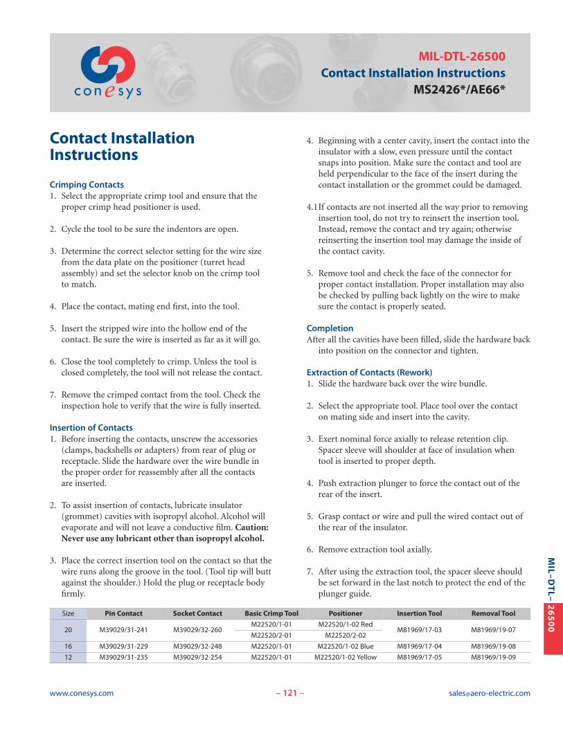
121www.conesys.com [email protected]
MIL–D
TL–
26500
MIL-DTL-26500Contact Installation Instructions
MS2426*/AE66*
– –
Contact InstallationInstructions
Crimping Contacts 1. Select the appropriate crimp tool and ensure that the
proper crimp head positioner is used.
2. Cycle the tool to be sure the indentors are open.
3. Determine the correct selector setting for the wire sizefrom the data plate on the positioner (turret head assembly) and set the selector knob on the crimp tool to match.
4. Place the contact, mating end first, into the tool.
5. Insert the stripped wire into the hollow end of the contact. Be sure the wire is inserted as far as it will go.
6. Close the tool completely to crimp. Unless the tool isclosed completely, the tool will not release the contact.
7. Remove the crimped contact from the tool. Check theinspection hole to verify that the wire is fully inserted.
Insertion of Contacts1. Before inserting the contacts, unscrew the accessories
(clamps, backshells or adapters) from rear of plug orreceptacle. Slide the hardware over the wire bundle in the proper order for reassembly after all the contacts are inserted.
2. To assist insertion of contacts, lubricate insulator (grommet) cavities with isopropyl alcohol. Alcohol willevaporate and will not leave a conductive film. Caution:Never use any lubricant other than isopropyl alcohol.
3. Place the correct insertion tool on the contact so that thewire runs along the groove in the tool. (Tool tip will buttagainst the shoulder.) Hold the plug or receptacle bodyfirmly.
4. Beginning with a center cavity, insert the contact into theinsulator with a slow, even pressure until the contactsnaps into position. Make sure the contact and tool areheld perpendicular to the face of the insert during thecontact installation or the grommet could be damaged.
4.1If contacts are not inserted all the way prior to removinginsertion tool, do not try to reinsert the insertion tool.Instead, remove the contact and try again; otherwisereinserting the insertion tool may damage the inside ofthe contact cavity.
5. Remove tool and check the face of the connector forproper contact installation. Proper installation may alsobe checked by pulling back lightly on the wire to makesure the contact is properly seated.
CompletionAfter all the cavities have been filled, slide the hardware back
into position on the connector and tighten.
Extraction of Contacts (Rework)1. Slide the hardware back over the wire bundle.
2. Select the appropriate tool. Place tool over the contact on mating side and insert into the cavity.
3. Exert nominal force axially to release retention clip.Spacer sleeve will shoulder at face of insulation whentool is inserted to proper depth.
4. Push extraction plunger to force the contact out of therear of the insert.
5. Grasp contact or wire and pull the wired contact out ofthe rear of the insulator.
6. Remove extraction tool axially.
7. After using the extraction tool, the spacer sleeve shouldbe set forward in the last notch to protect the end of theplunger guide.
Size Pin Contact Socket Contact Basic Crimp Tool Positioner Insertion Tool Removal Tool
20 M39029/31-241 M39029/32-260M22520/1-01 M22520/1-02 Red
M81969/17-03 M81969/19-07M22520/2-01 M22520/2-02
16 M39029/31-229 M39029/32-248 M22520/1-01 M22520/1-02 Blue M81969/17-04 M81969/19-08
12 M39029/31-235 M39029/32-254 M22520/1-01 M22520/1-02 Yellow M81969/17-05 M81969/19-09

MIL-DTL-26500 Bayonet and ThreadedInsert Availability and Contact Informationper MIL-STD-1554
Insert Availability and Contact Information
– – [email protected] 122
MIL–D
TL–
26500
InsertArrangement
Aero-Electric Total Quantity of Contacts Service Alternate Positions
Status No. of (by Size) (Insert Rotation in Degrees)
QPL’d Tooled Contacts 20 16 12 # 8 Coax Rating 1* 2* 3* 4* 5*
8-3 Yes Yes 3 3 I N/A N/A N/A N/A N/A
10-5 Yes Yes 5 5 I 10 20 30 40 50
12-3 Yes Yes 3 3 I 10 20 30 40 50
12-12 Yes Yes 12 12 I 10 20 30 40 50
14-4 Yes Yes 4 4 I 10 20 30 40 50
14-7 Yes Yes 7 7 I 10 20 30 40 50
14-12 Yes Yes 12 9 3 I 10 20 30 40 50
14-15 Yes Yes 15 15 I 10 20 30 40 50
16-10 Yes Yes 10 10 I 10 20 30 40 50
16-24 Yes Yes 24 24 I 10 20 30 40 50
18-8 Yes Yes 8 8 I 10 20 30 40 50
18-11 Yes Yes 11 10 1 I 10 20 30 40 50
18-14 Yes Yes 14 14 I 10 20 30 40 50
18-31 Yes Yes 31 31 I 10 20 30 40 50
20-16 Yes Yes 16 16 I 10 20 30 40 50
20-25 Yes Yes 25 19 6 I 10 20 30 40 50
20-39 Yes Yes 39 37 2 I 10 20 30 40 50
20-41 Yes Yes 41 41 I 10 20 30 40 50
22-12 Yes Yes 12 12 I 10 20 30 40 50
22-19 Yes Yes 19 19 I 10 20 30 40 50
22-55 Yes Yes 55 55 I 10 20 30 40 50
24-30** N/A Yes 30 30 I 10 20 30 40 50
24-43 Yes Yes 43 23 20 I 10 20 30 40 50
24-57 Yes Yes 57 55 2 I 10 20 30 40 50
24-61 Yes Yes 61 61 I 10 20 30 40 50
* Per MIL-STD-1554, insert positions 1 thru 5 are inactive for new design. ** Non MIL-STD-1554 layout, available to Aero-Electric part number only.
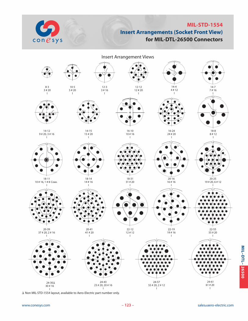
8-33 # 20
I
1
3
10-55 # 20
I
1
5
12-33 # 16
I
1
2 3
14-77 # 16
I
1
7
18-88 # 12
I
1
8
12-1212 # 20
I
1
12
14-129 # 20, 3 # 16
I
1
12
14-1515 # 20
I
1
15
16-1010 # 16
I
1
10
18-1414 # 16
I
1
14
18-3131 # 20
I
1
31
20-3937 # 20, 2 # 16
I
1
39
16-2424 # 20
I
1
24
20-1616 # 16
I
1
16
20-2519 # 20, 6 # 12
I
1
25
20-4141 # 20
I
1
41
18-1110 # 16, 1 # 8 Coax.
I
1
11
22-1919 # 16
I
19
1
22-5555 # 20
I
1
55
24-4323 # 20, 20 # 16
I
1
43
24-5755 # 20, 2 # 12
I
1
57
1 30
24-30D30 # 16
I
14-44 # 12
I
1
4
22-1212 # 12
I
1
12
24-6161 # 20
I
1
61
123www.conesys.com [email protected]
MIL–D
TL–
26500
MIL-STD-1554Insert Arrangements (Socket Front View)
for MIL-DTL-26500 Connectors
– –
Insert Arrangement Views
� Non MIL-STD-1554 layout, available to Aero-Electric part number only.

124www.conesys.com [email protected]
Part Number Cross Reference
Part Number Cross Reference, Status and Availability
– –
* Active – recommended for new design; Inactive – not recommended fornew design; Canceled – must use superseding part.
** Equivalent part from newer Series/Spec is intermateable and intermount-able; some differences in accessory threads and contact release may exist.
Note: Aero-Electric manufactures MIL-DTL- 26482 Series 2,MIL-DTL-5015 Series III (Rear Release), MIL-DTL-26500,MIL-DTL-83723 Series III and MIL-DTL-38999 Series I, II andIII. Only part numbers covered by these specifications are listed.
Military Available Description Contact Military Status* Superseding Available
Part from Shell Type Style Specification & Series of Equivalent** from
Number Aero (MIL-DTL-) Document MS Number Aero
D38999/20 Yes Wall Mount Receptacle P & S 38999 Series III Active — —D38999/21 No Box Mount Receptacle, Hermetic C, P, X 38999 Series III Active — —D38999/22 No Dummy Receptacle — 38999 Series III Active — —D38999/23 No Jam Nut Receptacle, Hermetic C, P, X 38999 Series III Active — —D38999/24 Yes Jam Nut Receptacle P & S 38999 Series III Active — —D38999/25 No Solder Mount Receptacle, Hermetic C, P, X 38999 Series III Active — —D38999/26 Yes RFI Grounding Plug P & S 38999 Series III Active — —D38999/27 No Weld Mount Receptacle, Hermetic C, P, X 38999 Series III Active — —D38999/28 No Hex Mounting Nut (Jam Nut) — 38999 Series III, IV Active — —D38999/29 No Lanyard Release Plug, Pin Contact P 38999 Series III Active — —D38999/30 No Lanyard Release Plug, Socket Contact S 38999 Series III Active — —D38999/31 No Lanyard Release Plug, SS 25, Pin P 38999 Series III Active — —D38999/32 No Metal Protective Cover, Plug — 38999 Series III Active — —D38999/33 No Metal Protective Cover, Receptacle — 38999 Series III Active — —M38999/1 No Grommet Nut (E-Nut) — 38999 Series I, II Canceled, Superseded by M85049/27 NoM38999/2 No Boot Adapter — 38999 Series I, II Canceled, Superseded by M85049/62 NoM38999/3 No EMI/RFI Crimp Ring Adapter — 38999 Series I, II Canceled, Superseded by M85049/33-2 NoM38999/4 No Individual Shield Termination Backshell — 38999 Series I, II Canceled, Superseded by M85049/30 NoM38999/5 No Straight Backshell, EMI, Environmental — 38999 Series I, II Canceled, Superseded by M85049/17 NoM38999/6 No Straight Backshell, Non Environmental — 38999 Series I, II Canceled, Superseded by M85049/29 NoM38999/7 No Straight Backshell, EMI/RFI — 38999 Series I, II Canceled, Superseded by M85049/36 NoM38999/8 No 90º Split Backshell, EMI/RFI — 38999 Series I, II Canceled, Superseded by M85049/37 NoM38999/9 No Dummy Receptacle — 38999 Series I Active — —M38999/10 No Dummy Receptacle — 38999 Series II Active — —M83723/1 No Narrow Flange Mount Receptacle S 83723 Series I Canceled, Superseded by MS3470 YesM83723/2 No Narrow Flange Mount Receptacle P 83723 Series I Canceled, Superseded by MS3470 YesM83723/3 No Wide Flange Mount Receptacle S 83723 Series I Canceled, Superseded by MS3472 YesM83723/4 No Wide Flange Mount Receptacle P 83723 Series I Canceled, Superseded by MS3472 YesM83723/5 No Jam Nut Receptacle S 83723 Series I Canceled, Superseded by MS3474 YesM83723/6 No Jam Nut Receptacle P 83723 Series I Canceled, Superseded by MS3474 YesM83723/7 No Cable Connecting Receptacle S 83723 Series I Canceled, Superseded by MS3471 YesM83723/8 No Cable Connecting Receptacle P 83723 Series I Canceled, Superseded by MS3471 YesM83723/9 No Narrow Flange Mt. Recept., Hermetic P 83723 Series I Canceled, Superseded by MS3440 NoM83723/10 No Wide Flange Mt. Recept., Hermetic P 83723 Series I Canceled, Superseded by MS3442 NoM83723/11 No Solder Mount Receptacle, Hermetic P 83723 Series I Canceled, Superseded by MS3443 NoM83723/12 No Jam Nut Receptacle, Hermetic P 83723 Series I Canceled, Superseded by MS3449 NoM83723/13 No Straight Plug S 83723 Series I Canceled, Superseded by MS3476 YesM83723/14 No Straight Plug P 83723 Series I Canceled, Superseded by MS3476 YesM83723/15A No 90º Strain Relief — 83723 Series I, III Canceled, Superseded by M85049/51 NoM83723/15N No Grommet Nut (E-Nut) — 83723 Series I, III Canceled, Superseded by M85049/31 NoM83723/15S No Straight Strain Relief — 83723 Series I, III Canceled, Superseded by M85049/52 NoM83723/16A No 90º Heat Shrink Boot — 83723 Series I Active — —M83723/16M No Boot Adapter — 83723 Series I Active M85049/60-2 NoM83723/16S No Straight Heat Shrink Boot — 83723 Series I Active — —

125www.conesys.com [email protected]
Part Number Cross Reference
Part Number Cross Reference, Status and Availability
– –
* Active – recommended for new design; Inactive – not recommended fornew design; Canceled – must use superseding part.
** Equivalent part from newer Series/Spec is intermateable and intermount-able; some differences in accessory threads and contact release may exist.
Note: Aero-Electric manufactures MIL-DTL- 26482 Series 2,MIL-DTL-5015 Series III (Rear Release), MIL-DTL-26500,MIL-DTL-83723 Series III and MIL-DTL-38999 Series I, II andIII. Only part numbers covered by these specifications are listed.
Military Available Description Contact Military Status* Superseding Available
Part from Shell Type Style Specification &Series of Equivalent** from
Number Aero (MIL-DTL-) Document MS Number Aero
M83723/17 No Cable Connecting Receptacle S 83723 Series II Inactive, Use MS3451 Yes
M83723/18 No Cable Connecting Receptacle P 83723 Series II Inactive, Use MS3451 Yes
M83723/19 No Wall Mount Receptacle S 83723 Series II Inactive, Use MS3450 Yes
M83723/20 No Wall Mount Receptacle P 83723 Series II Inactive, Use MS3450 Yes
M83723/21 No Box Mount Receptacle S 83723 Series II Inactive, Use MS3452 Yes
M83723/22 No Box Mount Receptacle P 83723 Series II Inactive, Use MS3452 Yes
M83723/23 No Straight Plug S 83723 Series II Inactive, Use MS3456 Yes
M83723/24 No Straight Plug P 83723 Series II Inactive, Use MS3456 Yes
M83723/25 No Wall Mount Receptacle, Hermetic P 83723 Series II Canceled, Superseded by MS3142 No
M83723/26 No Solder Mount Receptacle, Hermetic P 83723 Series II Canceled, Superseded by MS3143 No
M83723/27A No 90º Heat Shrink Boot — 83723 Series II Inactive — —
M83723/27M No Boot Adapter — 83723 Series II Inactive — —
M83723/27S No Straight Heat Shrink Boot — 83723 Series II Inactive — —
M83723/28 No Seal Plugs — 83723 Series I, III Canceled, Superseded by MS27488 Yes
M83723/29 No Pin Contacts (0 thru 16) P 83723 Series II Canceled, Superseded by M39029/29 Yes
M83723/30 No Socket Contacts (0 thru 16) S 83723 Series II Canceled, Superseded by M39029/30 Yes
M83723/31 No Insertion/Extraction Tools (20, 16, 12) — 83723 Series I, III Canceled, Superseded by M81969/14 Yes
M83723/32 No Insertion/Extraction Tools (0, 4, 8) — 83723 Series II Canceled, Superseded by M81969/14 Yes
M83723/33 No Pin Contacts (20, 16, 12) P 83723 Series I, III Canceled, Superseded by M39029/4 Yes
M83723/34 No Socket Contacts (20, 16, 12) S 83723 Series I, III Canceled, Superseded by M39029/5 Yes
M83723/35A No 90º Backshell with Cable Clamp — 83723 Series II Inactive — —
M83723/35N No Grommet Nut (E-Nut) — 83723 Series II Inactive — —
M83723/35S No Straight Backshell with Cable Clamp — 83723 Series II Inactive — —
M83723/36 No Pre-wired Plug for 8-2, 8-3, 8-4 Layouts only P 83723 Series I Canceled — —
M83723/37 Yes Pre-wired Plug for 8-2, 8-3, 8-4 Layouts only S 83723 Series I Inactive — —
M83723/38 NoPre-wired Narrow Flange Receptacle for 8-2, 8-3, 8-4 Layouts only
P 83723 Series I Canceled — —
M83723/39 NoPre-wired Narrow Flange Receptacle for 8-2, 8-3, 8-4 Layouts
S 83723 Series I Canceled — —
M83723/40 NoPre-wired Wide Flange Receptacle for 8-2, 8-3, 8-4 Layouts
P 83723 Series I Canceled — —
M83723/41 NoPre-wired Wide Flange Receptacle for 8-2, 8-3, 8-4 Layouts
S 83723 Series I Canceled — —
M83723/42 No RFI Grounding Plug P 83723 Series I Canceled, Superseded by MS3475 Yes
M83723/43 No RFI Grounding Plug S 83723 Series I Canceled, Superseded by MS3475 Yes
M83723/44 No Metal Protective Cover, Receptacle — 83723 Series I Canceled, Superseded by MS3181 No
M83723/45 No Dummy Receptacle — 83723 Series I Canceled, Superseded by MS3115 No
M83723/46 No Metal Protective Cover, Plug — 83723 Series I Canceled, Superseded by MS3180 No
M83723/47 No Shield Termination l, RFI Grounding — 83723 Series I Canceled, M85049/26 No
M83723/48 No Pre-wired RFI Plug for 8-2, 8-3, 8-4 Layouts only P 83723 Series I Canceled — —
M83723/49 No Pre-wired RFI Plug for 8-2, 8-3, 8-4 Layouts only S 83723 Series I Canceled — —
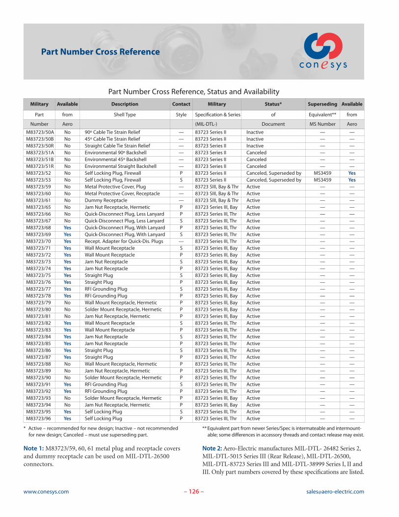
126www.conesys.com [email protected]
Part Number Cross Reference
Part Number Cross Reference, Status and Availability
– –
* Active – recommended for new design; Inactive – not recommendedfor new design; Canceled – must use superseding part.
Note 1: M83723/59, 60, 61 metal plug and receptacle coversand dummy receptacle can be used on MIL-DTL-26500connectors.
** Equivalent part from newer Series/Spec is intermateable and intermount-able; some differences in accessory threads and contact release may exist.
Note 2: Aero-Electric manufactures MIL-DTL- 26482 Series 2,MIL-DTL-5015 Series III (Rear Release), MIL-DTL-26500, MIL-DTL-83723 Series III and MIL-DTL-38999 Series I, II andIII. Only part numbers covered by these specifications are listed.
Military Available Description Contact Military Status* Superseding Available
Part from Shell Type Style Specification & Series of Equivalent** from
Number Aero (MIL-DTL-) Document MS Number Aero
M83723/50A No 90º Cable Tie Strain Relief — 83723 Series II Inactive — —M83723/50B No 45º Cable Tie Strain Relief — 83723 Series II Inactive — —M83723/50R No Straight Cable Tie Strain Relief — 83723 Series II Inactive — —M83723/51A No Environmental 90º Backshell — 83723 Series II Canceled — —M83723/51B No Environmental 45º Backshell — 83723 Series II Canceled — —M83723/51R No Environmental Straight Backshell — 83723 Series II Canceled — —M83723/52 No Self Locking Plug, Firewall P 83723 Series II Canceled, Superseded by MS3459 YesM83723/53 No Self Locking Plug, Firewall S 83723 Series II Canceled, Superseded by MS3459 YesM83723/59 No Metal Protective Cover, Plug — 83723 SIII, Bay & Thr Active — —M83723/60 No Metal Protective Cover, Receptacle — 83723 SIII, Bay & Thr Active — —M83723/61 No Dummy Receptacle — 83723 SIII, Bay & Thr Active — —M83723/65 No Jam Nut Receptacle, Hermetic P 83723 Series III, Bay Active — —M83723/66 No Quick-Disconnect Plug, Less Lanyard P 83723 Series III, Thr Active — —M83723/67 No Quick-Disconnect Plug, Less Lanyard S 83723 Series III, Thr Active — —M83723/68 Yes Quick-Disconnect Plug, With Lanyard P 83723 Series III, Thr Active — —M83723/69 Yes Quick-Disconnect Plug, With Lanyard S 83723 Series III, Thr Active — —M83723/70 Yes Recept. Adapter for Quick-Dis. Plugs — 83723 Series III, Thr Active — —M83723/71 Yes Wall Mount Receptacle S 83723 Series III, Bay Active — —M83723/72 Yes Wall Mount Receptacle P 83723 Series III, Bay Active — —M83723/73 Yes Jam Nut Receptacle S 83723 Series III, Bay Active — —M83723/74 Yes Jam Nut Receptacle P 83723 Series III, Bay Active — —M83723/75 Yes Straight Plug S 83723 Series III, Bay Active — —M83723/76 Yes Straight Plug P 83723 Series III, Bay Active — —M83723/77 Yes RFI Grounding Plug S 83723 Series III, Bay Active — —M83723/78 Yes RFI Grounding Plug P 83723 Series III, Bay Active — —M83723/79 No Wall Mount Receptacle, Hermetic P 83723 Series III, Bay Active — —M83723/80 No Solder Mount Receptacle, Hermetic P 83723 Series III, Bay Active — —M83723/81 No Jam Nut Receptacle, Hermetic P 83723 Series III, Bay Active — —M83723/82 Yes Wall Mount Receptacle S 83723 Series III, Thr Active — —M83723/83 Yes Wall Mount Receptacle P 83723 Series III, Thr Active — —M83723/84 Yes Jam Nut Receptacle S 83723 Series III, Thr Active — —M83723/85 Yes Jam Nut Receptacle P 83723 Series III, Thr Active — —M83723/86 Yes Straight Plug S 83723 Series III, Thr Active — —M83723/87 Yes Straight Plug P 83723 Series III, Thr Active — —M83723/88 No Wall Mount Receptacle, Hermetic P 83723 Series III, Thr Active — —M83723/89 No Jam Nut Receptacle, Hermetic P 83723 Series III, Thr Active — —M83723/90 No Solder Mount Receptacle, Hermetic P 83723 Series III, Thr Active — —M83723/91 Yes RFI Grounding Plug S 83723 Series III, Thr Active — —M83723/92 Yes RFI Grounding Plug P 83723 Series III, Thr Active — —M83723/93 No Solder Mount Receptacle, Hermetic P 83723 Series III, Bay Active — —M83723/94 No Jam Nut Receptacle, Hermetic P 83723 Series III, Bay Active — —M83723/95 Yes Self Locking Plug S 83723 Series III, Thr Active — —M83723/96 Yes Self Locking Plug P 83723 Series III, Thr Active — —
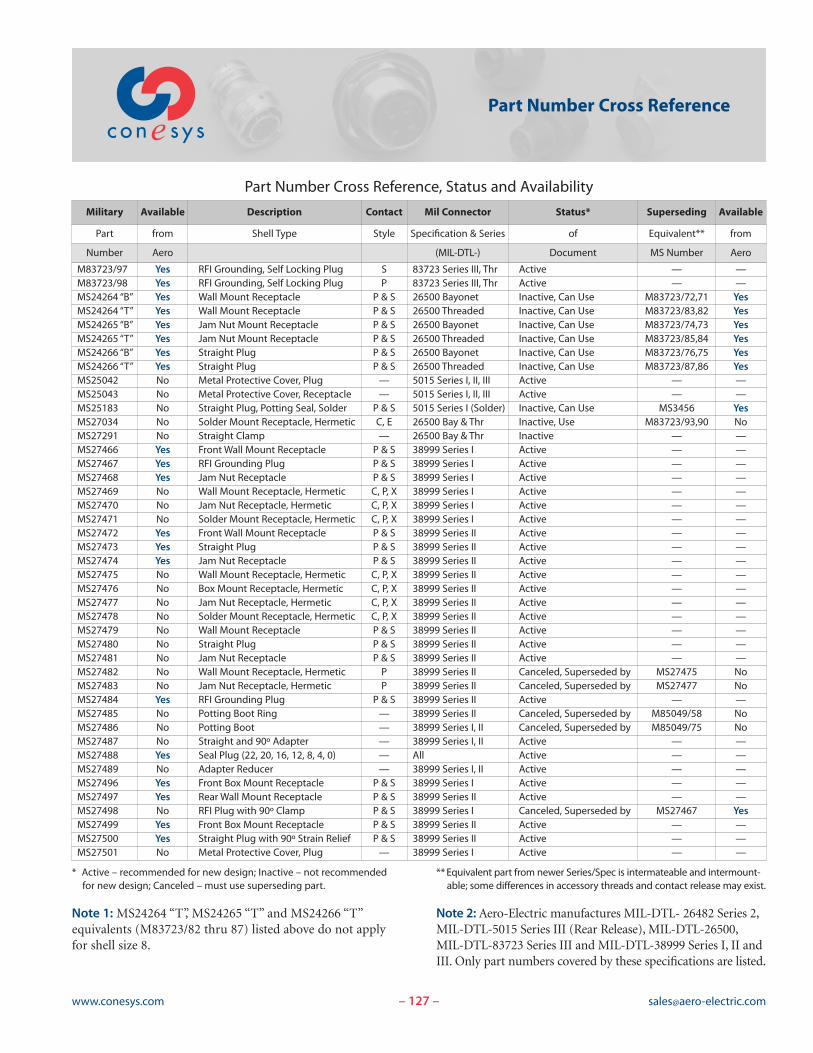
127www.conesys.com [email protected]
Part Number Cross Reference
Part Number Cross Reference, Status and Availability
– –
* Active – recommended for new design; Inactive – not recommendedfor new design; Canceled – must use superseding part.
Note 1: MS24264 “T”, MS24265 “T” and MS24266 “T”equivalents (M83723/82 thru 87) listed above do not applyfor shell size 8.
** Equivalent part from newer Series/Spec is intermateable and intermount-able; some differences in accessory threads and contact release may exist.
Note 2: Aero-Electric manufactures MIL-DTL- 26482 Series 2,MIL-DTL-5015 Series III (Rear Release), MIL-DTL-26500, MIL-DTL-83723 Series III and MIL-DTL-38999 Series I, II andIII. Only part numbers covered by these specifications are listed.
Military Available Description Contact Mil Connector Status* Superseding Available
Part from Shell Type Style Specification & Series of Equivalent** from
Number Aero (MIL-DTL-) Document MS Number Aero
M83723/97 Yes RFI Grounding, Self Locking Plug S 83723 Series III, Thr Active — —M83723/98 Yes RFI Grounding, Self Locking Plug P 83723 Series III, Thr Active — —MS24264 “B” Yes Wall Mount Receptacle P & S 26500 Bayonet Inactive, Can Use M83723/72,71 YesMS24264 “T” Yes Wall Mount Receptacle P & S 26500 Threaded Inactive, Can Use M83723/83,82 YesMS24265 “B” Yes Jam Nut Mount Receptacle P & S 26500 Bayonet Inactive, Can Use M83723/74,73 YesMS24265 “T” Yes Jam Nut Mount Receptacle P & S 26500 Threaded Inactive, Can Use M83723/85,84 YesMS24266 “B” Yes Straight Plug P & S 26500 Bayonet Inactive, Can Use M83723/76,75 YesMS24266 “T” Yes Straight Plug P & S 26500 Threaded Inactive, Can Use M83723/87,86 YesMS25042 No Metal Protective Cover, Plug — 5015 Series I, II, III Active — —MS25043 No Metal Protective Cover, Receptacle — 5015 Series I, II, III Active — —MS25183 No Straight Plug, Potting Seal, Solder P & S 5015 Series I (Solder) Inactive, Can Use MS3456 YesMS27034 No Solder Mount Receptacle, Hermetic C, E 26500 Bay & Thr Inactive, Use M83723/93,90 NoMS27291 No Straight Clamp — 26500 Bay & Thr Inactive — —MS27466 Yes Front Wall Mount Receptacle P & S 38999 Series I Active — —MS27467 Yes RFI Grounding Plug P & S 38999 Series I Active — —MS27468 Yes Jam Nut Receptacle P & S 38999 Series I Active — —MS27469 No Wall Mount Receptacle, Hermetic C, P, X 38999 Series I Active — —MS27470 No Jam Nut Receptacle, Hermetic C, P, X 38999 Series I Active — —MS27471 No Solder Mount Receptacle, Hermetic C, P, X 38999 Series I Active — —MS27472 Yes Front Wall Mount Receptacle P & S 38999 Series II Active — —MS27473 Yes Straight Plug P & S 38999 Series II Active — —MS27474 Yes Jam Nut Receptacle P & S 38999 Series II Active — —MS27475 No Wall Mount Receptacle, Hermetic C, P, X 38999 Series II Active — —MS27476 No Box Mount Receptacle, Hermetic C, P, X 38999 Series II Active — —MS27477 No Jam Nut Receptacle, Hermetic C, P, X 38999 Series II Active — —MS27478 No Solder Mount Receptacle, Hermetic C, P, X 38999 Series II Active — —MS27479 No Wall Mount Receptacle P & S 38999 Series II Active — —MS27480 No Straight Plug P & S 38999 Series II Active — —MS27481 No Jam Nut Receptacle P & S 38999 Series II Active — —MS27482 No Wall Mount Receptacle, Hermetic P 38999 Series II Canceled, Superseded by MS27475 NoMS27483 No Jam Nut Receptacle, Hermetic P 38999 Series II Canceled, Superseded by MS27477 NoMS27484 Yes RFI Grounding Plug P & S 38999 Series II Active — —MS27485 No Potting Boot Ring — 38999 Series II Canceled, Superseded by M85049/58 NoMS27486 No Potting Boot — 38999 Series I, II Canceled, Superseded by M85049/75 NoMS27487 No Straight and 90º Adapter — 38999 Series I, II Active — —MS27488 Yes Seal Plug (22, 20, 16, 12, 8, 4, 0) — All Active — —MS27489 No Adapter Reducer — 38999 Series I, II Active — —MS27496 Yes Front Box Mount Receptacle P & S 38999 Series I Active — —MS27497 Yes Rear Wall Mount Receptacle P & S 38999 Series II Active — —MS27498 No RFI Plug with 90º Clamp P & S 38999 Series I Canceled, Superseded by MS27467 YesMS27499 Yes Front Box Mount Receptacle P & S 38999 Series II Active — —MS27500 Yes Straight Plug with 90º Strain Relief P & S 38999 Series II Active — —MS27501 No Metal Protective Cover, Plug — 38999 Series I Active — —

128www.conesys.com [email protected]
Part Number Cross Reference
Part Number Cross Reference, Status and Availability
– –
* Active – recommended for new design; Inactive – not recommendedfor new design; Canceled – must use superseding part.
** Equivalent part from newer Series/Spec is intermateable and inter-mountable; some differences in accessory threads and contact releasemay exist.
� “Bayonet Coupling” equivalents do not exist.
Note 1: MS27615 standard threaded plug equivalent =M83723/87, 86 in K class. Note 2: Aero-Electric manufactures MIL-DTL- 26482 Series 2,MIL-DTL-5015 Series III (Rear Release), MIL-DTL-26500,MIL-DTL-83723 Series III and MIL-DTL-38999 Series I, II andIII. Only part numbers covered by these specifications are listed.
Military Available Description Contact Mil Connector Status* Superseding Available
Part from Shell Type Style Specification & Series of Equivalent** from
Number Aero (MIL-DTL-) Document MS Number Aero
MS27502 No Metal Protective Cover, Receptacle — 38999 Series I Active — —MS27504 No Box Mount Receptacle P & S 38999 Series II Active — —MS27505 Yes Rear Box Mount Receptacle P & S 38999 Series I Active — —MS27506 No Straight Strain Relief — 38999 Series I, II Canceled, Superseded by M85049/49 NoMS27507 No 90º Strain Relief — 38999 Series I, II Canceled, Superseded by M85049/47 NoMS27508 Yes Rear Box Mount Receptacle P & S 38999 Series II Active — —MS27510 No Metal Protective Cover, Plug — 38999 Series II Active — —MS27511 No Metal Protective Cover, Receptacle — 38999 Series II Active — —MS27512 No Hex Mounting Nut (Jam Nut) — 38999 Series II Inactive, Use MS3186 NoMS27513 Yes Front Box Mt. Receptacle, Long Grommet P & S 38999 Series II Active — —MS27515 No Rear Wall Mount Receptacle P & S 38999 Series I Inactive, Use MS27656 YesMS27534 No Insertion/Removal Tools — 38999 Series I, II Inactive, Use M81969/14 YesMS27535 No Size 8 Coax Contact, Socket S 38999 Series I Inactive, Use M39029/59 YesMS27536 No Size 8 Coax Contact, Pin P 38999 Series I Inactive, Use M39029/60 YesMS27558 No 90º Cable Support, Closed — 26500 Bay & Thr Inactive — —MS27559 No 90º Cable Clamp — 26500 Bay & Thr Inactive — —MS27613∆ No Wall Mount Receptacle, Firewall P & S 26500 Bay & Thr Inactive, Use M83723/83, 82 YesMS27614∆ No Jam Nut Receptacle, Firewall P & S 26500 Bay & Thr Inactive, Use M83723/85, 84 YesMS27615∆ No Ratchet Lock & Standard Plug, Firewall P & S 26500 Bay & Thr Inactive, Use M83723/96, 95 YesMS27652 No Wall Mount Receptacle P & S 38999 Series I Inactive, Use MS27466 YesMS27653 No Straight Plug P & S 38999 Series I Inactive, Use MS27467 YesMS27654 No Rear Wall Mount Receptacle P & S 38999 Series I Inactive, Use MS27656 YesMS27656 Yes Rear Wall Mount Receptacle P & S 38999 Series I Active — —MS27657 No Short Cable Support for Classes E, K — 26500 Bay & Thr Inactive — —MS27661 No Lanyard Release Plug P & S 38999 Series I Active — —MS27662 No Thru-Bulkhead Mounting Receptacle C 38999 Series I Active — —MS27663-1 No Straight Non-Metallic Strain Relief — 38999 Series I, II Canceled, Superseded by M85049/45 NoMS27663-2 No 90º Non-Metallic Strain Relief — 38999 Series I, II Canceled, Superseded by M85049/46 NoMS27664 No Rear Wall Mount Receptacle P & S 38999 Series II Canceled, Use MS27497 YesMS27667 No Thru-Bulkhead Mounting Receptacle C 38999 Series II Canceled — —MS27668 No Straight Cable Tie Strain Relief — 38999 Series I, II Canceled, Superseded by M85049/56 NoMS27669 No 45º Cable Tie Strain Relief — 38999 Series I, II Canceled, Superseded by M85049/57 NoMS27670 No 90º Cable Tie Strain Relief — 38999 Series I, II Canceled, Superseded by M85049/63 NoMS3100 No Wall Mount Receptacle P & S 5015 Series I (Solder) Inactive MS3450 YesMS3101 No Cable Connecting Receptacle P & S 5015 Series I (Solder) Inactive MS3451 YesMS3102 No Box Mount Recptacle P & S 5015 Series I (Solder) Inactive MS3452 YesMS3103 No Flange Mount Receptacle, Potting Seal P & S 5015 Series I (Solder) Inactive — —MS3105 No Dummy Receptacle — 5015 Series I (Solder) Inactive — —MS3106 No Straight Plug P & S 5015 Series I (Solder) Inactive MS3456 YesMS3107 No Quick Disconnect Plug P & S 5015 Series I (Solder) Inactive — —MS3108 No 90º Plug P & S 5015 Series I (Solder) Inactive MS3456 & B/S YesMS3110 No Wall Mount Receptacle P & S 26482 Series 1 Solder Inactive, Can Use MS3470 Yes
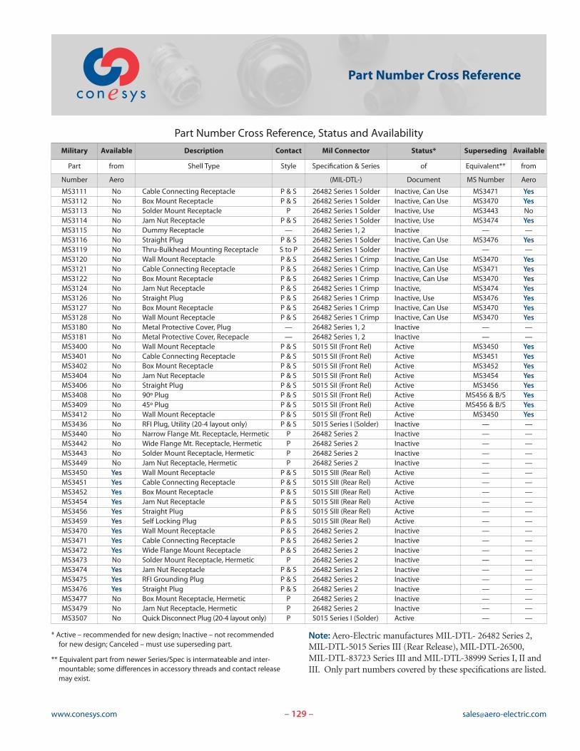
129www.conesys.com [email protected]
Part Number Cross Reference
Part Number Cross Reference, Status and Availability
– –
* Active – recommended for new design; Inactive – not recommendedfor new design; Canceled – must use superseding part.
** Equivalent part from newer Series/Spec is intermateable and inter-mountable; some differences in accessory threads and contact releasemay exist.
Note: Aero-Electric manufactures MIL-DTL- 26482 Series 2,MIL-DTL-5015 Series III (Rear Release), MIL-DTL-26500,MIL-DTL-83723 Series III and MIL-DTL-38999 Series I, II andIII. Only part numbers covered by these specifications are listed.
Military Available Description Contact Mil Connector Status* Superseding Available
Part from Shell Type Style Specification & Series of Equivalent** from
Number Aero (MIL-DTL-) Document MS Number Aero
MS3111 No Cable Connecting Receptacle P & S 26482 Series 1 Solder Inactive, Can Use MS3471 YesMS3112 No Box Mount Receptacle P & S 26482 Series 1 Solder Inactive, Can Use MS3470 YesMS3113 No Solder Mount Receptacle P 26482 Series 1 Solder Inactive, Use MS3443 NoMS3114 No Jam Nut Receptacle P & S 26482 Series 1 Solder Inactive, Use MS3474 YesMS3115 No Dummy Receptacle — 26482 Series 1, 2 Inactive — —MS3116 No Straight Plug P & S 26482 Series 1 Solder Inactive, Can Use MS3476 YesMS3119 No Thru-Bulkhead Mounting Receptacle S to P 26482 Series 1 Solder Inactive — —MS3120 No Wall Mount Receptacle P & S 26482 Series 1 Crimp Inactive, Can Use MS3470 YesMS3121 No Cable Connecting Receptacle P & S 26482 Series 1 Crimp Inactive, Can Use MS3471 YesMS3122 No Box Mount Receptacle P & S 26482 Series 1 Crimp Inactive, Can Use MS3470 YesMS3124 No Jam Nut Receptacle P & S 26482 Series 1 Crimp Inactive, MS3474 YesMS3126 No Straight Plug P & S 26482 Series 1 Crimp Inactive, Use MS3476 YesMS3127 No Box Mount Receptacle P & S 26482 Series 1 Crimp Inactive, Can Use MS3470 YesMS3128 No Wall Mount Receptacle P & S 26482 Series 1 Crimp Inactive, Can Use MS3470 YesMS3180 No Metal Protective Cover, Plug — 26482 Series 1, 2 Inactive — —MS3181 No Metal Protective Cover, Recepacle — 26482 Series 1, 2 Inactive — —MS3400 No Wall Mount Receptacle P & S 5015 SII (Front Rel) Active MS3450 YesMS3401 No Cable Connecting Receptacle P & S 5015 SII (Front Rel) Active MS3451 YesMS3402 No Box Mount Receptacle P & S 5015 SII (Front Rel) Active MS3452 YesMS3404 No Jam Nut Receptacle P & S 5015 SII (Front Rel) Active MS3454 YesMS3406 No Straight Plug P & S 5015 SII (Front Rel) Active MS3456 YesMS3408 No 90º Plug P & S 5015 SII (Front Rel) Active MS456 & B/S YesMS3409 No 45º Plug P & S 5015 SII (Front Rel) Active MS456 & B/S YesMS3412 No Wall Mount Receptacle P & S 5015 SII (Front Rel) Active MS3450 YesMS3436 No RFI Plug, Utility (20-4 layout only) P & S 5015 Series I (Solder) Inactive — —MS3440 No Narrow Flange Mt. Receptacle, Hermetic P 26482 Series 2 Inactive — —MS3442 No Wide Flange Mt. Receptacle, Hermetic P 26482 Series 2 Inactive — —MS3443 No Solder Mount Receptacle, Hermetic P 26482 Series 2 Inactive — —MS3449 No Jam Nut Receptacle, Hermetic P 26482 Series 2 Inactive — —MS3450 Yes Wall Mount Receptacle P & S 5015 SIII (Rear Rel) Active — —MS3451 Yes Cable Connecting Receptacle P & S 5015 SIII (Rear Rel) Active — —MS3452 Yes Box Mount Receptacle P & S 5015 SIII (Rear Rel) Active — —MS3454 Yes Jam Nut Receptacle P & S 5015 SIII (Rear Rel) Active — —MS3456 Yes Straight Plug P & S 5015 SIII (Rear Rel) Active — —MS3459 Yes Self Locking Plug P & S 5015 SIII (Rear Rel) Active — —MS3470 Yes Wall Mount Receptacle P & S 26482 Series 2 Inactive — —MS3471 Yes Cable Connecting Receptacle P & S 26482 Series 2 Inactive — —MS3472 Yes Wide Flange Mount Receptacle P & S 26482 Series 2 Inactive — —MS3473 No Solder Mount Receptacle, Hermetic P 26482 Series 2 Inactive — —MS3474 Yes Jam Nut Receptacle P & S 26482 Series 2 Inactive — —MS3475 Yes RFI Grounding Plug P & S 26482 Series 2 Inactive — —MS3476 Yes Straight Plug P & S 26482 Series 2 Inactive — —MS3477 No Box Mount Receptacle, Hermetic P 26482 Series 2 Inactive — —MS3479 No Jam Nut Receptacle, Hermetic P 26482 Series 2 Inactive — —MS3507 No Quick Disconnect Plug (20-4 layout only) P 5015 Series I (Solder) Active — —

130www.conesys.com [email protected]
Glossary of Terms
– –
Aaccessories Sometimes referred to as “Rear Accessories” or“Backshells” are mechanical devices such as strain reliefs,cable clamps, adapters, potting boots, etc., which are threadedonto the rear connector accessory threads of plug or recep-tacle connectors to make up the total connector assembly.adapter A threaded ring device screwed onto the threads ofan 83723 Series III threaded receptacle to accept a quick disconnect plug.
Bback mounted Rear mounted – a connector with itsmounting flange mounted inside of a panel or box. bayonet coupling A quick coupling mechanism for matinga plug onto a receptacle utilizing three equally spaced pinsprotruding from the receptacle shell which engage corre-sponding ramps milled into the coupling nut of the matingplug. Mating and unmating is accomplished by rotating thecoupling nut.BIN code Basic identification number - color bands on thewire barrel end of a contact to identify contact part number.Each BIN number corresponds to one and only one slashsheet (XX) thus identifying the complete M39029/XX-BINpart number.boot A form placed onto the boot adapter used to environ-mentally seal and/or strain-relieve a cable assembly. boot adapter A mechanical device with one side threadedonto the accessory thread of a connector (plug or receptacle)and the other side used to accept a boot.braid Braided wire – flexible conductor made of woven orbraided assembly of wires.bussing The joining of two or more circuits.
Ccable clamp A mechanical device attached to the accessorythreads at the rear of a plug or receptacle to support thecable or wire bundle, to provide strain relief and absorbvibration and shock which would otherwise be transmittedby the cable to the contact or wire crimp area.coaxial contact A contact with two conductive surfaces – acenter contact and a surrounding coaxial sleeve.color coding A system of identification of contact insertion/extraction tools. Colors green, red, orange, blue,yellow and white indicate the proper tool to use for eitherinsertion or extraction of appropriate contact size.connector A mechanical device, either a plug or a receptacle,used to terminate or connect electrical conductors (pin andsocket contacts) of a cable and its individual wires and providea means to continue or terminate these conductors to a mating connector which may be mounted on electrical
equipment panels, thru bulkheads, printed circuit boards, etc.contact Pin or socket – the conductive element of a connector which actually makes contact for the purpose ofconducting electrical current. This is the heart of the connector.contact area The actual area in contact (touching)between two conductors (pin and socket) permitting theflow of electrical current. contact arrangement The number of contacts, their sizeand spacing in a connector.contact engagement/separation force The force necessaryto engage or separate pin and socket contacts.contact resistance The electrical resistance on a matedpair of contacts (pin and socket). Resistance is measured inohms or millivolt drop at a specified current over theengaged contacts.contact retainer Contact retention clip – a device captivatedin the hard plastic of the connector body (insert) whichretains the contact in the insert.contact retention The axial load in either direction (pushor pull) which a contact can withstand without being dis-lodged from its normal position within the insert of theconnector.contact size A specific number indicating the size (or gauge)of the engaging end of the contact; examples: size 20, size 16,size 8, etc.contact shoulder The flanged portion around the body ofa contact which limits its forward travel into the insert andprevents it from being pushed forward out of the insert.coupling nut/ring The movable portion of a connectorplug which aids in the coupling and uncoupling of a plugand a receptacle and locks the plug and receptacle together.crimp The physical compression (uniformed deformation)of a contact wire barrel around the conductor in order tocaptivate the conductor and make an electrical connection.crimping A pressure method using a tool to mechanicallysecure a contact (pin or socket) to a conductor (wire). crimp contact A contact, pin or socket, whose back portion(wire barrel) is a hollow cylinder into which a stripped wire(conductor) is inserted. The sidewalls of the wire barrel arethen mechanically compressed (uniformly deformed) usinga crimping tool to captivate the conductor.crimp die Portion of the crimp tool that shapes the crimpon the wire barrel.crimp tool Mechanical device that holds the crimp die andis used to perform the crimping function.
Ddepth of crimp The distance the crimp die indenter penetrates into the wire barrel.

131www.conesys.com [email protected]
Glossary of Terms
– –
die closure The distance between the crimp die indenterswhen the crimp tool handle is at full closure. This is usuallychecked using a Go/No Go gauge.dielectric A material having electrical insulating properties.
Eenvironmental sealing Designed in a connector usinggrommets, interfacial seals, peripheral seals, gaskets or pottingmaterial to keep contaminants such as dirt and moisture outof the connector.extraction tool Removal tool – a tool used to remove contacts from a connector.
Ffilter contact A contact which provides filtering of EMIsignals without altering its normal function.filter connector A connector using filtered contacts or filtereddiscs to filter EMI signals without altering its normal function.front mounting A connector mounted with its mountingflange outside of a box or panel.front release A term indicating the direction the contactremoval tool must enter the connector to allow for theremoval of contacts. On a front release connector, the contactremoval tool must be inserted in the contact cavity from thefront or face of the connector to release the contact retentionclip. Whether front release or rear release, the contacts areinserted from the rear of the connector.
Ggrommet A resilient elastomeric seal bonded to the rear of a connector. It is designed with internal sealing barriersthat grasp and seal on the wire's insulation to prevent contaminants from entering into the rear of the connector.grounding fingers Grounding spring – a metal band withspring fingers attached to the plug shell to ensure positiveshell-to-shell grounding before the contacts engage duringmating and when they disengage during unmating. They arealso used to improve EMI/RFI performance.
Iinsert The insulating core of the connector designed to posi-tion, retain, support and provide separation for the contacts.insertion tool A tool used to insert contacts into a connector.inspection hole A hole at the bottom of the contact wirebarrel to permit visual inspection to ensure that the wire hasbeen inserted to the proper depth in the wire barrel prior tocrimping. insulation Jacket– insulating material around a wire or cable.interface The two surfaces on the contact side of a mating
plug and receptacle. The surfaces will face each other andinterface when mated.interfacial seal The sealing of mating connectors over theentire area of the interface and around each contact. This isaccomplished when resilient material, with raised barriersaround each cavity on the pin interface, displaces into thehard recessed (chamfered) cavities on the socket interface.This creates what is commonly called “cork and bottle seal.”
Jjacket Insulation – insulating material around a wire or cable.
Kkey A rectangular projection on plug connector shelldesigned to slide into the rectangular slot or keyway in themating receptacle connector to properly align and guide thetwo mating halves together. Generally used to obtain properpolarization.
Llanyard A sturdy wire attached to plugs of certain connectors which allows unmating and separation of plugand receptacle by a pull on the wire (lanyard).locator Positioner or Turret head – a mechanical deviceattached to a crimp tool with multiple locators to positiondifferent size contacts for crimping. It is indexed to a properposition by rotating.
Mmate The joining of two connectors.mated pair A plug and receptacle joined or to be joinedtogether.millivolt drop Voltage loss due to resistance created by acrimp joint.
O“O” ring Also referred to as peripheral seal is used aroundthe periphery of a connector shell and is compressed internally between the plug and receptacle shells whenmated to prevent contaminants from entering the connector.
Ppin contact A “male” contact with the engagement endthat enters into the socket contact.plating The overlaying of a thin coating of metal on connector shells and contacts to prevent corrosion, improveconductivity or provide for easy soldering.plug The “free to move” or “unmounted” member of a matedpair of connectors which contains the coupling ring/nut for

132www.conesys.com [email protected]
Glossary of Terms
– –
coupling and locking the connectors together.polarization Also known as clocking or keying – themechanical arrangement of inserts or rectangular keys (projections) and keyways (slots) to ensure proper mating.It eliminates errors when mating identical connectorsmounted beside each other.positioner Locator or Turret head – a device attached to acrimp tool with multiple locators to position different sizecontacts for crimping. It is indexed to a proper position byrotating.potting The permanent sealing of the back of a connector,after the wires have been inserted, with a material to keepout the contaminants and/or provide strain relief.potting boot a form fitted onto the potting ring , which isthreaded onto the back of connector, to environmentallyseal/strain relive a cable assembly.pull out force The force necessary to separate a wire fromthe contact crimped to it or the force necessary to pull aproperly seated contact from a connector by pulling.pull test Tensile test – a controlled pull test on the contactcrimp joint to determine its mechanical strength.
Rrange Wire range – the acceptable sizes of wires accommodated by a particular contact wire barrel size. Also the acceptable diameter of wires accommodated by asealing grommet.rear accessories Referred to as backshells, they aremechanical devices that screw onto the accessory threads onthe rear of the connector. Includes strain reliefs, clamps,adapters, potting boots, etc.rear mounted Back mounted – a connector with itsmounting flange mounted inside of a panel or box.rear release A term indicating the direction the contactremoval tool must enter the connector to allow removal ofthe contacts. On a rear release connector the contactremoval tool must be inserted into the contact cavity fromthe back or rear of the connector to release the contactretention clip. Whether rear release or front release, contactsare inserted through the rear of the connector.receptacle The fixed or mounted member of a mated pairof connectors designed to be mounted to a box, panel orbulkhead.removal tool A device used to remove contacts from aconnector.
Ssafety wire A means of putting wire through holes drilled inthe coupling ring/nut of a connector plug, and securing thewire to a panel of bulkhead to prevent the plug from loosening
or decoupling from the receptacle during vibration.scoop proof A term to describe a longer shell design onthe pin half (plug or receptacle) of a connector. The longershell allows the pin contacts, which protrude from the faceof the connector, to be recessed sufficiently so as not to bedamaged if the mating shell is “scooped” into it during matingprocess. This prevents pins from being bent and/or contactsfrom being electrically shorted during mating. This is espe-cially important when using size 22 contacts, which becauseof their small size, bend easily.sealing plug A small plastic plug (MS27488-**-1, head first)inserted into the rear grommet of a connector, especially anenvironmental connector, to seal and prevent the entry ofcontaminants into any unused (unwired) cavities.selective plating The applying of plating material to a limited area of a contact, especially areas susceptible to wear.service rating The maximum amount of voltage or currenta connector is designed to continuously carry.shell The outside case of a connector which holds thedielectric insert and contacts.shielded contact A contact shielded from unwanted signals(EMI/RFI) by one or more outer (protective) conductors.These contacts are not generally matched to the impedanceof the cable they terminate.socket contact A contact whose engaging end is designedto accept the entry of a pin contact.solder contact A pin or socket contact that accepts a conductor (wire) which is soldered onto the “solder cup,”not crimped into the wire barrel.splice Wire splice – a device used to join two or more conductors (wires).strip To remove insulation from a conductor. Generally forinserting the conductor into the wire barrel/solder cup of acontact for a crimping/soldering operation.
Ttensile test Pull test – a controlled pull test on the contactcrimp joint to determine its mechanical strength.thermocouple contact A contact made of special material,used in connectors in high temperature applications as ameans of measuring temperature electrically. Materials oftenused for these contacts are alumel, chromel, constantan,iron and copper.threaded coupling A means of coupling a mating pair ofconnectors by engaging threads on the exterior of a receptaclewith interior threads of the plug.turret head Locator or Positioner - a device attached to acrimp tool with multiple locators to position different sizecontacts for crimping. It is indexed to a proper position byrotating.

Aero-Electric Connector Aero-Electric Connector - CAGE CODE: 59976
Catalog AE101A (11/2010)Specifications are subject to change without notice. Consult Aero-Electric Connector for latest design specifications. All statements, information and data provided herein are believed to be accurate and reliable but are presented without guarantee, warranty or responsibility of any kind, expressed or implied. The user should not assume that all safety measures are indicated or that other measures may not be required.
Drawing dimensions are in inches with metric equivalents provided in parentheses, for reference only, except in MIL-DTL-38999 Series III where dimensionsare in millimeters with inch equivalents in parentheses, for reference only.

www.conesys.com
Aero Industrial Products10138 Radiance Drive
Ira Township, Michigan 48023Tel: 586.716.1257Fax: [email protected]
J-Tech548 Amapola Ave.
Torrance, California 90501Tel: 310.533.6700Fax: [email protected]
Conesys Europe20, avenue Jean-Monnet31770 Colomiers. FranceTel: 33.5.61.15.34.20Fax: 33.5.61.15.48.11
EMP Connectors548 Amapola Ave.
Torrance, California 90501Tel: 310.222.5780Fax: [email protected]
Aero-Electric Connector2280 208th St.
Torrance, California 90501Tel: 310.618.3737Fax: 310.618.3738