AerE 243L: Incompressible Aerodynamicsrajagopa/2006F/pdf-files/243L.pdf · AerE 243L:...
41
AerE 243L: Incompressible Aerodynamics • AIM : Qualitative and quantitative understanding of aerodynamic characteristics of bodies. • Theory class (AFD) integrates with experimental lab (EFD). • FlowLab integrates CFD with AFD and EFD. Flow Physics Computational Fluid Dynamics (CFD) Analytical Method (AFD) Experimental Method (EFD)
-
Upload
hoangkhuong -
Category
Documents
-
view
220 -
download
0
Transcript of AerE 243L: Incompressible Aerodynamicsrajagopa/2006F/pdf-files/243L.pdf · AerE 243L:...

AerE 243L: Incompressible Aerodynamics
• AIM : Qualitative and quantitative understanding of aerodynamic characteristics of bodies.
• Theory class (AFD) integrates with experimental lab (EFD).
• FlowLab integrates CFD with AFD and EFD.
Flow Physics
ComputationalFluid Dynamics
(CFD)
Analytical Method(AFD)
ExperimentalMethod(EFD)

What is CFD ?
• numerically solve the governing equations that describe the physical phenomena.– Continuity equation
– N-S equation (momentum equation)
– Energy conservation equation
– State equation
• computer-based analysis technique
Components of CFD Analysis
• Preprocessing
• Solving
• Postprocessing

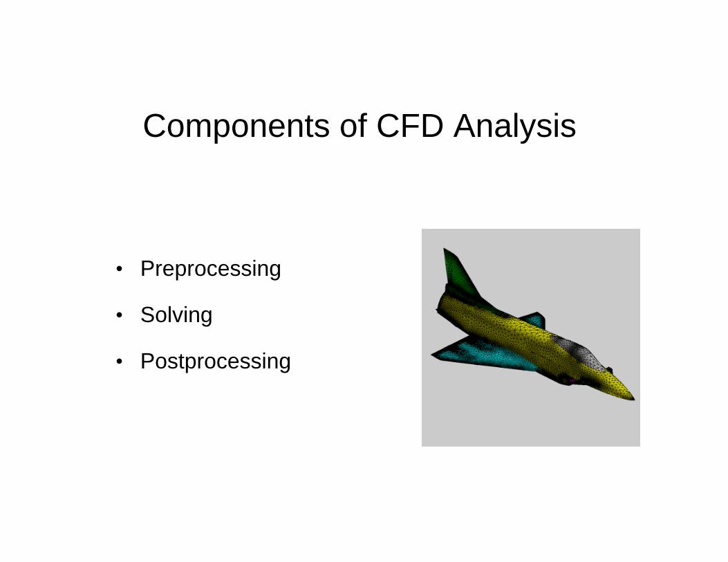
Grid generationThe aim is to create a highly automated structured viscous body-fitted grid generator hybridized with a Cartesian unstructured grid.
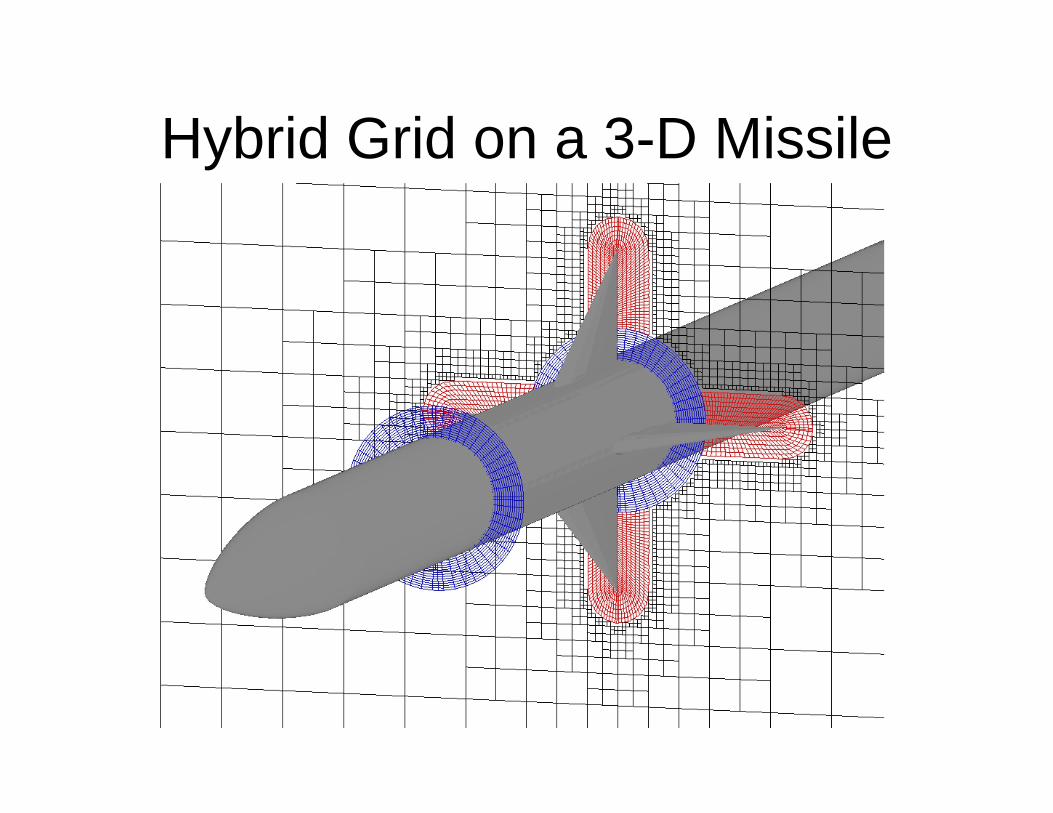
Hybrid Grid on a 3-D Missile

Ducted Fans CH46, V-22 & LHA

CH-46, V-22 and LHA

Experimental techniques for fluid diagnosticsExperimental techniques for fluid diagnostics
Flow Flow diagnosticdiagnostictechniquestechniques
Traditional Traditional (intrusive)(intrusive)
OpticalOptical––based based NonNon--intrusiveintrusive
•• PitotPitot probeprobe•• hotwire, hot filmhotwire, hot film•• thermocouplesthermocouples•• etc ...etc ...
•• Laser Doppler Laser Doppler VelocimetryVelocimetry (LDV)(LDV)•• Planar Doppler Planar Doppler VelocimetryVelocimetry (PDV)(PDV)•• Particle Image Particle Image VelocimetryVelocimetry (PIV(PIV))•• etcetc……
particleparticle--based based techniquestechniques
•• Laser Induced Fluorescence (LIF)Laser Induced Fluorescence (LIF)•• Molecular Tagging Molecular Tagging VelocimetryVelocimetry (MTV)(MTV)•• Molecular Tagging Molecular Tagging TherometryTherometry (MTT)(MTT)•• etc etc ……
moleculemolecule--based based techniquestechniques
Velocity, temperature, density (concentration), etc..
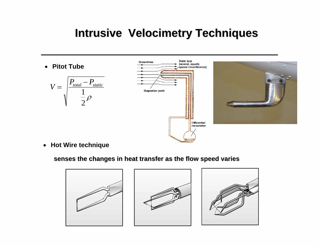
Intrusive Velocimetry TechniquesIntrusive Velocimetry Techniques
• Hot Wire technique
• Pitot Tube
ρ21
statictotal PPV −=
senses the changes in heat transfer as the flow speed variessenses the changes in heat transfer as the flow speed varies

Particle Image Particle Image VelocimetryVelocimetry (PIV) technique(PIV) technique
•• The technical basis of the PIV: The technical basis of the PIV: to to measure the displacementsmeasure the displacements of the of the tracer particlestracer particlesseeded in the flow in a fixed time interval. seeded in the flow in a fixed time interval.
tLUΔΔ
=
t=t0
t= t0+ΔtΔL

““ClassicalClassical”” Particle Image Particle Image VelocimetryVelocimetry (PIV) Technique(PIV) Technique• To seed fluid flows with small particles, and assume the tracer particles to have
the same velocity as fluid flows.• To measure the displacements (ΔL) of the tracer particles between known time
interval (Δt). The local velocity of fluid flow is calculated by U= Δ L/Δt .
• Measurement results:– velocity field (two component)– vorticity field (one component)
Illumination system(Laser and optics)
cameraSynchronizer
seed flow withtracer particles
Host computer
A. t=t0 B. t=t0+4ms
PIV measurement in a sloshing flow
-50 0 50 100 150 200 250 300-50
0
50
100
150
200-25.00 -20.00 -15.00 -10.00 -5.00 0.00 5.00 10.00 15.00 20.00 25.00
Spanwise Vorticity ( Z-direction )
Re =6,700
Uin = 0.33 m/s
X mm
Ym
m
Uou
t
water free surface
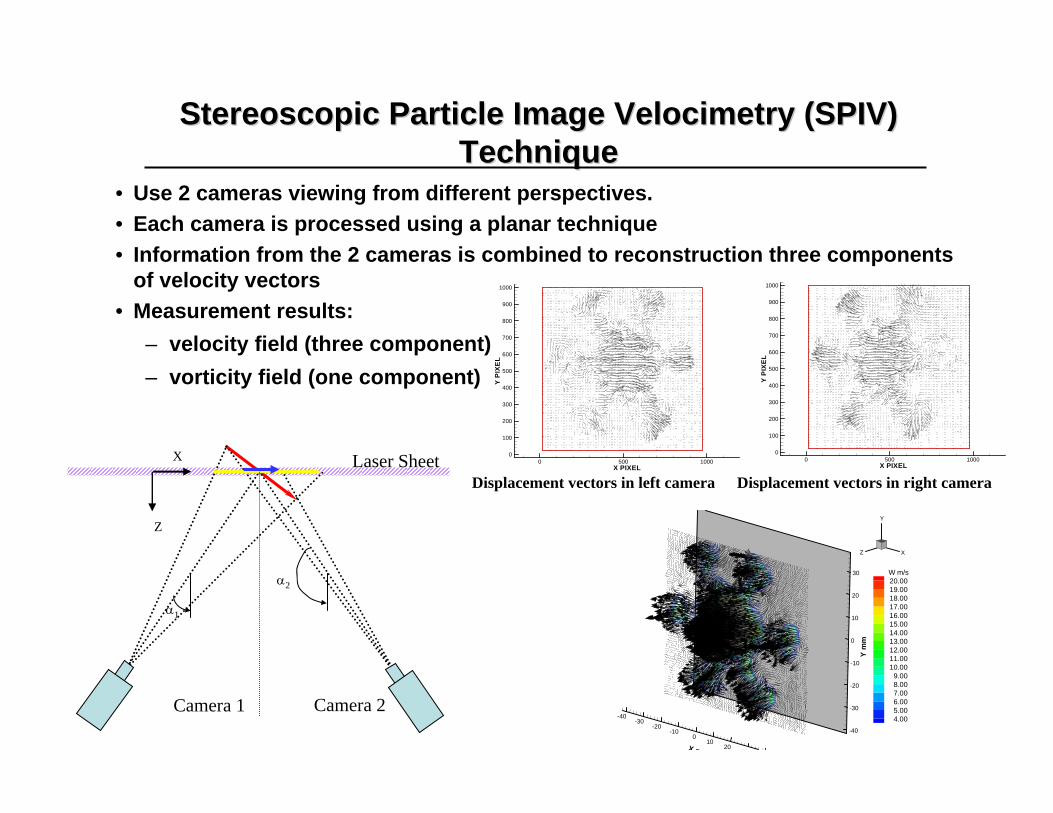
Stereoscopic Particle Image Stereoscopic Particle Image VelocimetryVelocimetry (SPIV) (SPIV) TechniqueTechnique
• Use 2 cameras viewing from different perspectives.• Each camera is processed using a planar technique• Information from the 2 cameras is combined to reconstruction three components
of velocity vectors• Measurement results:
– velocity field (three component)– vorticity field (one component)
Camera 1 Camera 2
Laser Sheet
α1
α2
Z
XX PIXEL
YP
IXE
L
0 500 10000
100
200
300
400
500
600
700
800
900
1000
X PIXEL
YP
IXE
L
0 500 10000
100
200
300
400
500
600
700
800
900
1000
Displacement vectors in left camera Displacement vectors in right camera
-40-30
-20-10
010
2030X m
-40
-30
-20
-10
0
10
20
30
Ym
m
X
Y
Z
W m/s20.0019.0018.0017.0016.0015.0014.0013.0012.0011.0010.00
9.008.007.006.005.004.00

AeroAero--engine:engine:enhance mixing between hot highenhance mixing between hot high--speed flow exhaust from speed flow exhaust from corecore--engineenginewith cold lowwith cold low--speed bypass flowspeed bypass flow•• civilian airplanes: civilian airplanes: reduce jet noise during takereduce jet noise during take--off and landingoff and landingthrust augmentationthrust augmentation
•• Military airplanes: Military airplanes: reduce the length of the hot plume, therefore, reduce the length of the hot plume, therefore, reduce the infrared emission signals to improve reduce the infrared emission signals to improve its survivability from the attack of infrared its survivability from the attack of infrared guided missiles. guided missiles.
Combustion: Combustion: enhance mixing between the fuel with enhance mixing between the fuel with air in the combustion chamberair in the combustion chamber•• improve combustion efficiencyimprove combustion efficiency•• suppression pollutant formationsuppression pollutant formation
Concept of Lobed Mixer/NozzleConcept of Lobed Mixer/Nozzle
Lobed mixer/nozzle Lobed mixer/nozzle
NASA modelNASA model
Turbo-fan aero-engine
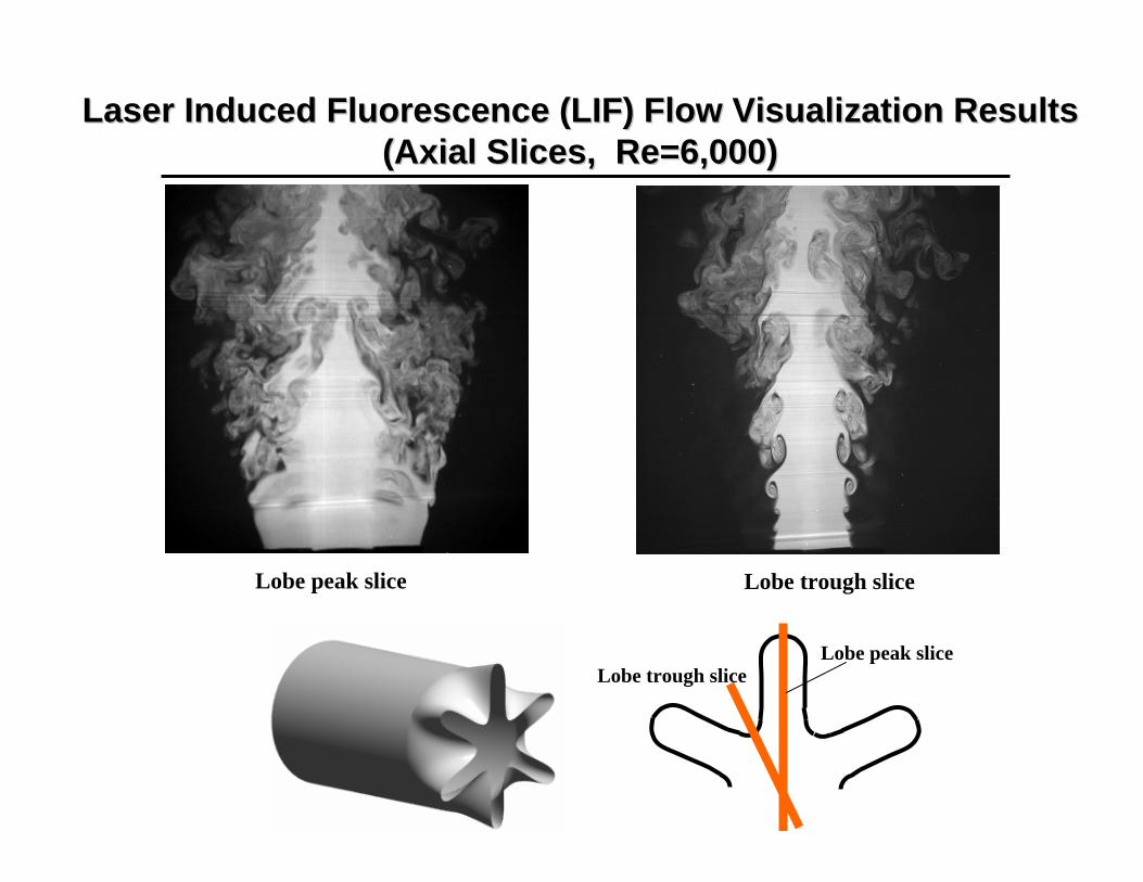
Laser Induced Fluorescence (LIF) Flow Visualization ResultsLaser Induced Fluorescence (LIF) Flow Visualization Results(Axial Slices, Re=6,000)(Axial Slices, Re=6,000)
Lobe trough sliceLobe peak slice
Lobe trough sliceLobe peak slice

X/D=1.0 X/D=1.5 X/D=2.0
X/D=0.25 X/D=0.5 X/D=0.75
Laser Induced Fluorescence (LIF) Flow Visualization ResultsLaser Induced Fluorescence (LIF) Flow Visualization Results(Cross Sections, Re=3,000)(Cross Sections, Re=3,000)

-30-20
-100
1020
30X mm
-30
-20
-10
0
10
20
30
Ym
m
X
Y
Z W m/s20.0019.0018.0017.0016.0015.0014.0013.0012.0011.0010.00
9.008.007.006.005.004.003.00
20 m/s
A. Instantaneous velocity field at Z=10mm plane
B. the simultaneous velocity field at Z=12mm plane
The Simultaneous Measurement Results of theThe Simultaneous Measurement Results of theDualDual--plane Stereoscopic PIV System at Two Parallel Planesplane Stereoscopic PIV System at Two Parallel Planes
-30-20
-100
1020
30X mm
-30
-20
-10
0
10
20
30
Ym
m
X
Y
Z W m/s20.0019.0018.0017.0016.0015.0014.0013.0012.0011.0010.00
9.008.007.006.005.004.003.00
20 m/s
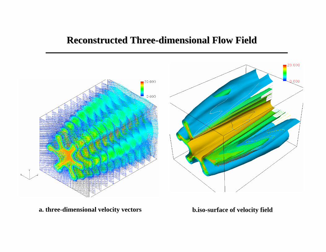
a. three-dimensional velocity vectors b.iso-surface of velocity field
Reconstructed ThreeReconstructed Three--dimensional Flow Fielddimensional Flow Field

Applications: MTV Measurements of the Vortex Applications: MTV Measurements of the Vortex Shedding from an Oscillating AirfoilShedding from an Oscillating Airfoil
Strong concentrated vortices are formed immediately at the trailing edge.
Instantaneous streamlines are highly curved near the trailing edge.
Note the location and sign of the vortices formed at the trailing edge.
Using the grid tagging method, the in-plane velocity components and the vorticity field are mapped. Data below are for k = 11.5.

Effect of Buoyancy Force on the Wake Instability Effect of Buoyancy Force on the Wake Instability of a Heated Cylinder in a Contra Flowof a Heated Cylinder in a Contra Flow
RiRiDD>>1.0 >>1.0 free convection free convection RiRiDD<<1.0<<1.0 forced convectionforced convectionRiRiDD ≈≈ 1.01.0 mixed convectionmixed convection
Present experimental parameters:Present experimental parameters:TTfluidfluid = 24.0 = 24.0 °°C , C , UUinin=0.026m/s, =0.026m/s, D=4.76mm,D=4.76mm, Re=130,Re=130,
The temperature of the cylinder (The temperature of the cylinder (TTww) ) 24.0 24.0 °°CC ~ 83~ 83.0 .0 °°CCCorresponding Corresponding Richardson numbers (Richardson numbers (RiRiDD)) 0.00 ~ 1.050.00 ~ 1.05Heat transfer around the heated cylinderHeat transfer around the heated cylinder Forced convectionForced convection ~ ~ Mixed convectionMixed convection
incoming flowincoming flow
gravitygravitydirectiondirection
heated cylinderheated cylinder
∞>TTw
buoyancybuoyancyforceforce
∞TUin ,forceviscousforcebuoyancy)DT-(TgG
forceviscousforceinertiaUDRe
2
3s
D
==
==
∞
νβ
ν
Dr
forceinertiaforcebuoyancy
ReGrRi 2
D
DD ∝=
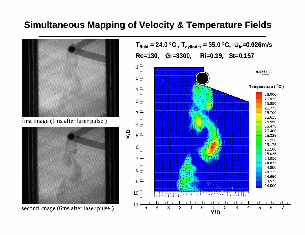
Simultaneous Mapping of Velocity & Temperature FieldsSimultaneous Mapping of Velocity & Temperature Fields
first image (1ms after laser pulse ) first image (1ms after laser pulse )
TTfluidfluid = 24.0 = 24.0 °°C , TC , Tcylindercylinder = 35.0 = 35.0 °°C, C, UUinin=0.026m/s=0.026m/s
Re=130,Re=130, GrGr=3300, =3300, RiRi=0.19, St=0.157=0.19, St=0.157
second image (6ms after laser pulse ) second image (6ms after laser pulse ) Y/D
X/D
-5 -4 -3 -2 -1 0 1 2 3 4 5 6 7
-1
0
1
2
3
4
5
6
7
8
9
10
11
26.00025.92525.85025.77525.70025.62525.55025.47525.40025.32525.25025.17525.10025.02524.95024.87524.80024.72524.65024.57524.500
Temperature ( OC )
0.026 m/s
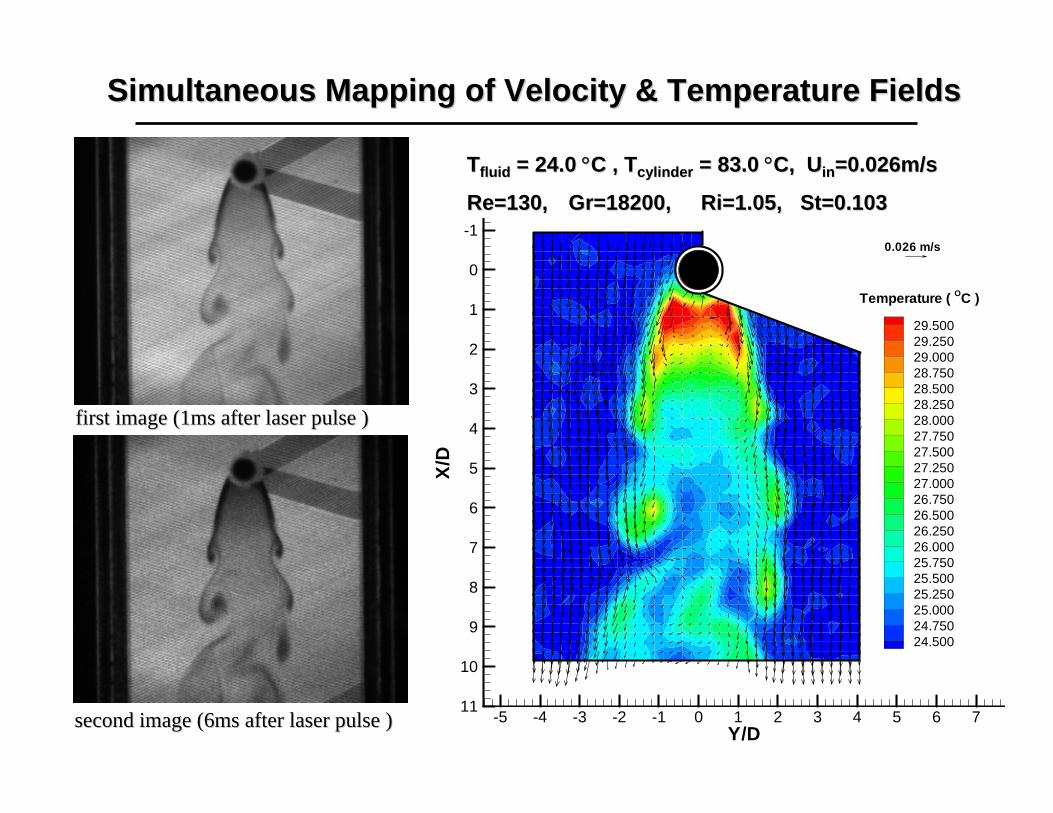
Simultaneous Mapping of Velocity & Temperature FieldsSimultaneous Mapping of Velocity & Temperature Fields
first image (1ms after laser pulse ) first image (1ms after laser pulse )
TTfluidfluid = 24.0 = 24.0 °°C , TC , Tcylindercylinder = 83.0 = 83.0 °°C, C, UUinin=0.026m/s=0.026m/s
Re=130,Re=130, GrGr=18200, =18200, RiRi=1.05, St=0.103=1.05, St=0.103
second image (6ms after laser pulse ) second image (6ms after laser pulse ) Y/D
X/D
-5 -4 -3 -2 -1 0 1 2 3 4 5 6 7
-1
0
1
2
3
4
5
6
7
8
9
10
11
29.50029.25029.00028.75028.50028.25028.00027.75027.50027.25027.00026.75026.50026.25026.00025.75025.50025.25025.00024.75024.500
Temperature ( OC )
0.026 m/s

AerE 243L: Incompressible Aerodynamics
• Concept 1:AFD : streamlines, pathlines and streaklinesEFD : flow visualization
• Concept 2:AFD : Bernoulli’s equationEFD : wind tunnel calibration

AerE 243L: Incompressible Aerodynamics
• Concept 3:
AFD : potential flow over a cylinder
EFD : flow over a cylinder
pressure distribution on the cylinder and drag estimation
CFD : all of the above and flow field analysis and visualization

AerE 243L: Incompressible Aerodynamics
• Concept 4:
AFD : introduction to airfoil characteristics
( Cl vs α, Cd vs α and Cm vs α )
EFD : same as AFD and analysis of the pressure distribution.
CFD : all of the above and flow field analysis and visualization

Flow Visualization
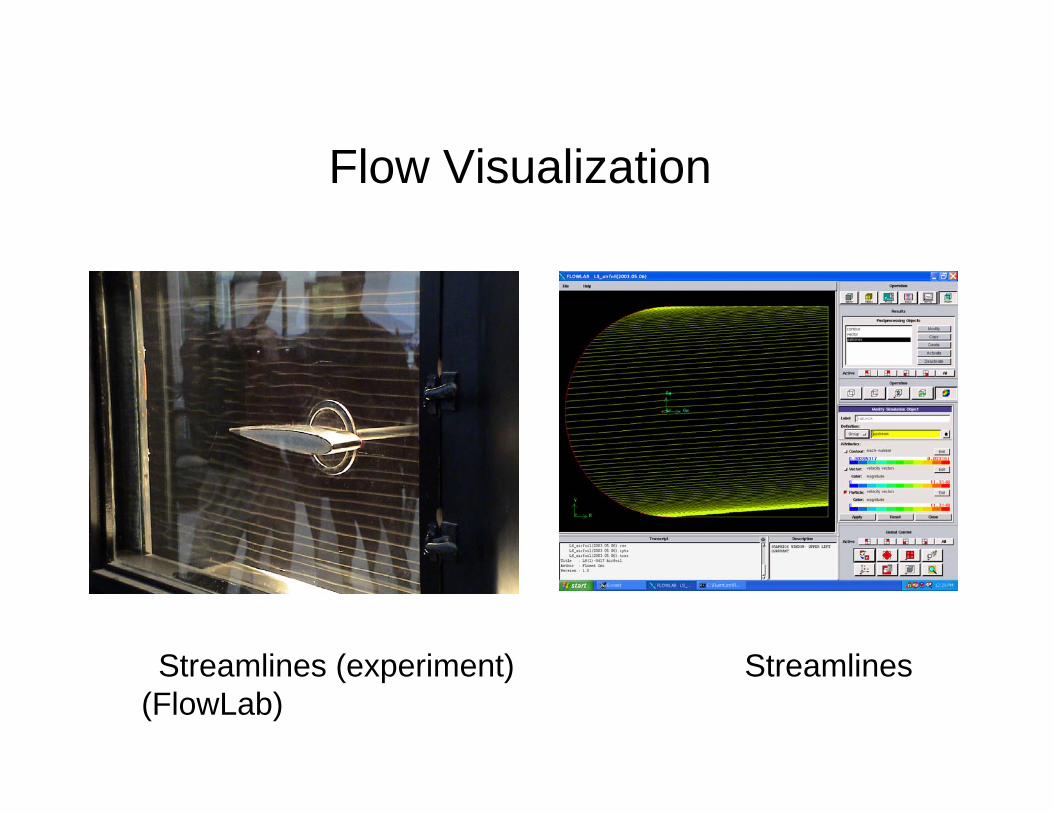
Flow Visualization
Streamlines (experiment) Streamlines (FlowLab)
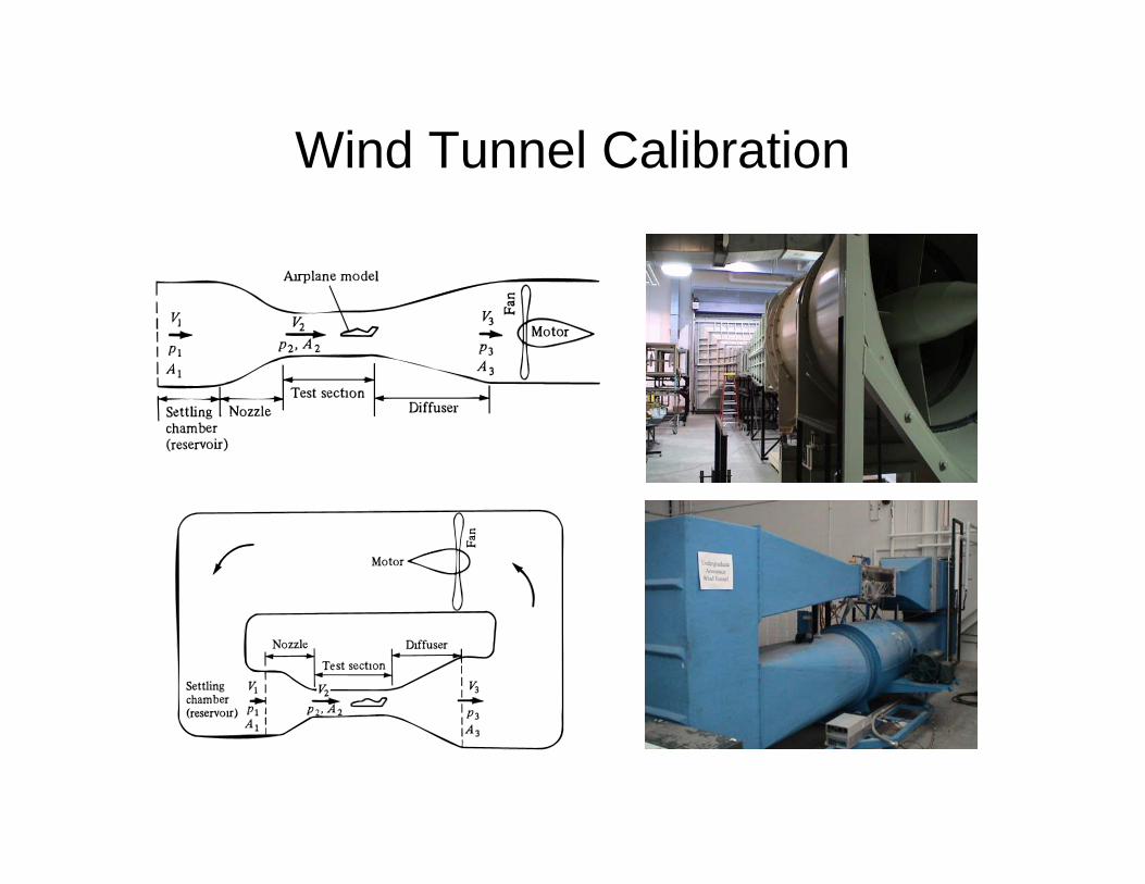
Wind Tunnel Calibration

Flow over a Circular Cylinder
Synthesis of lifting flow over a circular cylinder

Flow over a Circular Cylinder
Experimental model for measuring the pressure distributions along the circular cylinder surface (outside diameter = 3.25 inch)

Flow over a Circular Cylinder
Mesh for the numerical calculation of the flow over a circular cylinder

Flow over a Circular Cylinder
Numerical results for the velocity magnitude and pressure distributions over a circular cylinder using FlowLab(Vh=35.8 m/s, Re=1.89E+05)

Flow over a Circular Cylinder
Cp distributions over a circular cylinder
-3.5
-3
-2.5
-2
-1.5
-1
-0.5
0
0.5
1
1.5
0 1 2 3 4 5 6 7
theta (rad ) -->
cp --
>
EFDCFDAFD

FlowLab Templates Introduced• Circular cylinder• 2-D airfoils
Clark-Y airfoil LS(1)-0417 airfoil
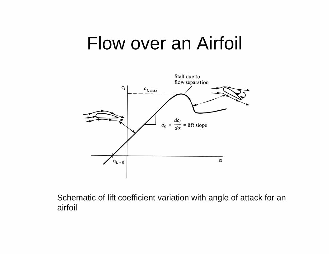
Flow over an Airfoil
Schematic of lift coefficient variation with angle of attack for an airfoil

Flow over an Airfoil
Experimental data for lift coefficient and moment coefficient about the ¼ chord point for an NACA 2412 airfoil

Flow over an Airfoil
Experimental data for profile drag coefficient and moment coefficient about the aerodynamic center for the NACA 2412 airfoil

Flow over an Airfoil
Experimental model for measuring the pressure distributions along the LS(1)-0417 airfoil surface

Flow over an Airfoil
airfoil (New airfoil Structured mesh for the numerical calculation of the flow over a LS(1)-0417 template)

Flow over an Airfoil
Numerical results for the Mach number and pressure distributions over LS(1)-0417 airfoil using the FlowLab(angle of attack=4 degree, Mh=0.025, Re=2.0E+05)

Flow over an Airfoil-1.5
-1
-0.5
0
0.5
1
1.5
0 0.2 0.4 0.6 0.8 1 1.2
x/c -->
c p --
>
EFD
CFD
Cp distributions over LS(1)-0417 airfoil

Questions?