
Aeration Terraces for Biological low-pH Iron(II) Oxidation …files.dep.state.pa.us/Mining/Abandoned...
24
1 Final Report RFP Number OSM PA(AMD-06) Commonwealth of Pennsylvania Department of Environmental Protection Bureau of Abandoned Mine Reclamation Division of Acid Mine Drainage Abatement Aeration Terraces for Biological low-pH Iron(II) Oxidation of Acid Mine Drainage April 20, 2010 William D. Burgos* ,1 John M. Senko 1 Mary Ann Bruns 2 The Pennsylvania State University 1 Department of Civil and Environmental Engineering 2 Department of Crop and Soil Sciences *Principal Investigator – address: Department of Civil and Environmental Engineering, The Pennsylvania State University, 212 Sackett Building, University Park, PA, 16802-1408; telephone: 814-863-0578; fax: 814-863-7304: e-mail: [email protected]
Transcript of Aeration Terraces for Biological low-pH Iron(II) Oxidation …files.dep.state.pa.us/Mining/Abandoned...

1
Final Report
RFP Number OSM PA(AMD-06)
Commonwealth of Pennsylvania
Department of Environmental Protection
Bureau of Abandoned Mine Reclamation
Division of Acid Mine Drainage Abatement
Aeration Terraces for Biological low-pH Iron(II)
Oxidation of Acid Mine Drainage
April 20, 2010
William D. Burgos*,1 John M. Senko1
Mary Ann Bruns2
The Pennsylvania State University 1 Department of Civil and Environmental Engineering
2 Department of Crop and Soil Sciences
*Principal Investigator – address: Department of Civil and Environmental Engineering, The Pennsylvania State University, 212 Sackett Building, University Park, PA, 16802-1408; telephone: 814-863-0578; fax: 814-863-7304: e-mail: [email protected]
2
TABLE OF CONTENTS
List of Figures 3
1. Introduction 5
2. Site Description 5
3. Field Sampling 7
4. Laboratory Experiments 7
5. Field Experiments 8
6. Results 11
6.1. Field Measurements 11
6.2. Laboratory Results 11
6.3. Sediment Characterizations 18
7. Assessment of Proposed Objectives 18
8. Conclusions 20

3
LIST OF FIGURES
Figure 1. Upper photo – Emergence of the Hughes Borehole discharge and location of “fence” samples described in this report (October 2006). Lower photo – Uphill view across the iron mound towards the Hughes Borehole (May 2007). The measuring tape is laid out along the “B-transect” and follows the primary channel as depicted in Figure 4. The “C-transect” follows the shallow terraces across the wet area uphill of the B-transect. The pilot test channels shown in Figure 3 were located on the mound on the left side of this photo.
Figure 2. Photos of “gutter” reactors constructed and operated in the Environmental Engineering
Laboratories at Penn State University. Water flows from the upper right to the lower left through square PVC tubes (1-in square by 36-in long). A large carboy filled with Hughes Borehole water is wrapped in brown plastic to exclude light and is continuously purged with N2(g) to minimize Fe(II) oxidation during storage and use. A peristaltic pump (barely visible behind the upper end of the reactors) is used to convey water from the carboy to the top of the gutters. Two of the gutters were filled with approximately 125 g of sediment, packed to a sediment bed thickness of ca. 0.25 in, while the other two gutters contained no sediment.
Figure 3. Photos of pilot-scale experimental facility constructed on the Hughes Borehole iron
mound. Water is conveyed from primary discharge channel through a 3-inch PVC pipe into the “splitter” box and then into eight, 40-foot long channels. Upper photo (looking uphill) was taken in June 2008 shortly after construction. Lower photo was taken in October 2008 after installation of plastic filter media in six of the eight channels (looking downhill). Channels are identified from right to left in the upper photo (i.e. upstream view) as A – H.
Figure 4. Schematic of sampling locations on the Hughes Borehole iron mound used for collecting
water and sediment samples. The light blue rectangle designates the fenced enclosure around the emergent discharge (referred to as sample D). All downstream distances (included in parentheses measured in meters) were measured from D. The left-hand “B-transect” followed the primary channel from the weir. The right-hand “C-transect” followed shallow sheet flow that spread out, fan-like across the mound. Samples were collected from these locations in August 2007 and December 2007 in order to capture “hot” and “cold” weather conditions, respectively.
Figure 5. Seasonal variations in dissolved Fe(II) concentrations, pH, dissolved oxygen (DO)
concentrations, pH, and temperature across the Hughes Borehole iron mound. B-transect (circle symbols) and C-transect (square symbols) refer to sampling locations shown in Figure 4. Samples were collected in August 2007 (filled symbols) and December 2007 (open symbols).
Figure 6. A) Concentrations of Fe(II) measured at the “fence” (nearest the borehole) and at the “toe” of
the iron mound over the course of this study. Speciation of Fe(II) and Fe(III) measured at B) the fence, and C) at the toe.

4
Figure 7. Comparison of A) pH, B) dissolved oxygen concentrations, and C) temperature at the “fence” (nearest the borehole) and at the “toe” of the iron mound over the course of this study.
Figure 8. Characterization of water chemistry flowing through the pilot-scale channels constructed on
the Hughes Borehole iron mound. A) Dissolved Fe(II) concentrations, B) pH, and C) dissolved oxygen concentrations.
Figure 9. Fe(II) oxidation kinetics measured in laboratory batch experiments using various organic
amendments and Hughes Borehole iron mound sediments. Figure 10. Fe(II) oxidation measured in laboratory flow-through “gutter” reactor experiments using
Hughes Borehole iron mound sediments. A) Effluent concentrations of Fe(II) normalized to corresponding influent concentrations of Fe(II), B) pH, and C) dissolved oxygen concentrations versus number of pore volumes (PVs) of reactor operation. Channels 1 and 2 were duplicate gutters that contained no sediment, while channels 3 and 4 were duplicate gutters that contained iron mound sediments. A 10 h residence time was maintained from 0 to 31 PVs, a 5 h residence time was maintained from 33 to 97 PVs, a 2 h residence time was maintained from 100 to 143 PVs, and a 1 hour residence time was maintained from 144 to 176 PVs.
Figure 11. Effect of hydraulic residence time on the removal efficiency of A) Fe(II), and B) total Fe
based on flow-through “gutter” reactor experiments conducted with Hughes Borehole iron mound sediments.
Figure 12. X-ray diffraction patterns from sediments collected from the top 2 cm from various locations
across the Hughes Borehole iron mound. The upper black line is from a shallow terrace, the middle red line is from the main channel, and the lower blue line is from the bottom of a shallow pool. Reference powder diffraction files for Schwertmannite and Goethite are included for comparison.
Figure 13. Scanning electron microscopy (SEM) images from sediments collected from the top 2 cm
from various locations across the Hughes Borehole iron mound. Upper left panel obtained from main channel. Upper right panel is corresponding energy dispersive spectroscopy (EDS) results from upper left panel showing elemental spectra for Fe, S, O and C. Lower left panel obtained from a pool, and lower right panel obtained from a meander. Scale bars noted in each panel.

5
Aeration Terraces for Biological low-pH Iron(II) Oxidation of Acid Mine Drainage
(Project Number OSM PA(AMD-06)_##?##)
1. Introduction This project was supported by the Commonwealth of Pennsylvania’s Department of Environmental Protection (DEP), Bureau of Abandoned Mine Reclamation (BAMR), Cambria office in response to their Request for Proposals for “Innovative Mine Drainage In-Situ or Ex-Situ Treatment or Abatement, or Enhanced Metals Recovery”, RFP No. OSM PA(AMD-06). The purpose of this research was to study biological low-pH Fe(II) oxidation at high flow (e.g. > 250 gal/min) AMD discharges to understand this process so that it can be exploited in engineered systems. This project was awarded in April 2007, and has focused on the Hughes Borehole near Portage, Pennsylvania in Cambria County.
This project completed the following three tasks (as detailed in the original proposal): (1) field
sampling events at the Hughes Borehole to measure water chemistry changes across the iron mound; (2)
laboratory experiments with Hughes Borehole sediments to measure the kinetics of low-pH Fe(II)
oxidation in carefully controlled batch and flow-through experiments; and (3) pilot-scale experiments on
a portion of the Hughes Borehole iron mound to promote low-pH Fe(II) oxidation under field conditions.
2. Site Description
The Hughes Borehole is located about 1.5 miles northeast of Portage, on the northwest bank of
the Little Conemaugh River (40o 24̒ 31.69144˝ N, 78o 39̒ 17.18372˝ W). We commonly accessed the
site from Sportsman Road near Jamestown, parking in a resident’s driveway and wading across the river.
The Hughes Borehole drains a very large Lower Kittanning deep coal mine that extends over 3,400 acres.
Historical water quality data has been collected for this discharge, designated HU01 by BAMR, and
average values include 714 gal/min flow rate, pH 3.88 (field), 197 mg CaCO3/L acidity, 75 mg Fe/L, 2.3
mg Mn/L, 8.3 mg Al/L and 512 mg SO4/L (GAI Consultants, 2007). AMD emerges up through a large
diameter borehole as an artesian source within a fenced enclosure. Mound sediments have been trenched
and bermed (or scoured and deposited over time) to direct the flow down a single primary channel and
through a rectangular weir (Figure 1). This weir was constructed the spring of 2006 and includes a
pressure transducer that allows for continuous flow rate monitoring. Based on this flow measuring
system, the average flow rate has been 1172 gal/min for measurements collected from October 2006 to
May 2008. At times of high flow rate, we have observed water flowing in multiple directions from the
fenced enclosure.
Beyond the weir, the iron mound is cut by several deep channels that convey the bulk of the water
at a high velocity across the mound and into a small creek. This creek forms the southwestern/
downstream edge of the iron mound and discharges into the Little Conemaugh River shortly after
capturing all of the flow from the borehole. Water also flows and spreads across shallow “terraces” that
have formed naturally on the mound. The site was surveyed in December 2007 and we estimate that the
total area of the mound is 1.5 acres, and that the maximum elevation drop from the enclosure fence to the
“toe” of the iron mound is ca. 8 feet over ca. 275 linear feet. The “toe” of the iron mound is the
hydrologic low point where the majority of the borehole water eventually discharges into the small creek.

Figure 1. Upper photo – Emergence of the Hughes Borehole discharge and location of “fence” samples described in this report (October 2006). Lower photo – Uphill view across the iron mound towards the Hughes Borehole (May 2007). The measuring tape is laid out along the “B-transect” and follows the primary channel as depicted in Figure 4. The “C-transect” follows the shallow terraces across the wet area uphill of the B-transect. The pilot test channels shown in Figure 3 were located on the mound on the left side of this photo.

7
3. Field Sampling
Water samples were collected across the iron mound, from the emergent source to the small creek
that captures the flow, in August 2007 and December 2007. Water samples were also collected, on a
more frequent basis, from the “fence” (i.e., just above the weir) and the “toe” of the mound. Water
samples were filtered (0.2-um) and properly preserved in the field, and stored on ice for transport to Penn
State. Dissolved oxygen (DO), pH, temperature, and conductivity were measured in the field using
portable meters.
Dissolved Fe(II) was measured by the ferrozine assay. Total Fe was measured, as Fe(II), after
reducing water samples with sodium dithionite and then using the ferrozine assay. Fe(III) was then
calculated as the difference between total Fe(II) and dissolved Fe(II). Dissolved Al, Ca, K, Mg, Mn, Na,
Si, and Fe content of sediments were measured by inductively coupled plasma emission spectrometry
(ICP-AES). Sulfate was measured using the HACH SulfaVer 4 method. Total organic carbon (TOC) and
total nitrogen (TN) were measured using a Shimadzu TOC/TN analyzer (Shimadzu Corp., Columbia,
MD).
Sediment samples were collected across the iron mound for bacterial enumerations, mineralogical
characterizations and laboratory experiments. Sediments were collected from the top 2-cm of the iron
mound at each location. Total sediment bacteria were enumerated by direct microscopic counts after
extracting the sediments with 50 mM NaH2PO4 (pH 3) and staining the cells with DAPI. Fe(II)-oxidizing
bacteria (Fe(II)OB) were specifically enumerated by a plate counting technique described by Johnson
(1995). In this method sediments are suspended in growth medium (0.2 g sediment/5 mL medium) and
serially diluted onto agarose plates (referred to as the “overlayer”). Because hydrolysis of the agarose
may inhibit the growth of Fe(II)OB, an “underlayer” plate was prepared and inoculated with the
acidophilic organoheterotrophic bacterium Acidophilium organovorum before pouring. The inclusion of
A. organovorum in the underlayer served to minimize the accumulation of agarose hydrolysis products in
the overlayer. Fe(II)OB colony forming units (CFU) were indicated by the formation of red-orange
colonies. Sediment samples were also preserved in the field for electron microscopy by adding
glutaraldehyde (2% v/v). Sediments were air dried and analyzed by X-ray diffraction (XRD) for
mineralogical characterizations.
4. Laboratory Experiments
All laboratory experiments were conducted with Hughes Borehole iron mound sediments and site
water collected above the weir (nearest the borehole). Batch experiments were typically conducted with
10.0 g moist sediment and 50.0 mL AMD with various nutrient amendments added to evaluate their effect
on the kinetics of low-pH Fe(II) oxidation. “Killed” controls were carried along with all experiments
where 1 % (v/v) of formaldehyde was added to the reactors to inactivate biological activity. Reactors
were sampled over time to measure aqueous Fe(II), 0.5 N HCl-extractable Fe(II), pH, DO and, less
frequently, phosphate, TOC and TN. Nutrient amendments tested included Stagreen fertilizer,
phosphorus-free fertilizer, Jobes tree spikes, coconut fiber, straw, and hardwood mulch. Nutrient
amendments were tested both in their solid form and in a “leachate” form. For solid nutrient addition to
sediment-containing reactors, solid nutrients were ground or cut into small sieve sizes. For leachate
8
addition, solid nutrients were “leached” into filter-sterilized AMD for over 24 hours, and the filtrates from
these solutions were then added to non-sterile, AMD-only-containing reactors.
Flow-through experiments were conducted using so-called “gutter” reactors (Figure 2). Gutter
reactors were constructed from PVC hollow square tubes and measured approximately 36-in long, by 1-in
square. Iron mound sediments were packed into the gutters by pouring the sediment through a funnel and
using a miniature rake to evenly spread it across the channel. Each gutter was filled with approximately
125 g of sediment, packed to a sediment bed thickness of ca. 0.25 in. Hughes Borehole site water was
collected in gallon containers and transported on ice to Penn State where all containers were combined
into a single 20 gallon carboy. Site water was collected on a frequent basis (e.g., every 2-3 weeks) in
order to maintain the volume of water required for these flow-through experiments. To minimize Fe(II)
oxidation, the carboy was sealed and maintained under a N2 atmosphere by continuous sparging. The site
water used for these experiments was never filtered or sterilized. A peristaltic pump was used to convey
water from the carboy to the head of the gutters. Samples were collected at the influent and effluent end
of the gutters and used to measure Fe(II), Fe(III), pH and DO. “No sediment” control gutters were run in
parallel with all experiments to evaluate the effect of sediment biomass on Fe(II) oxidation.
Gutter reactor experiments were begun at a low flow rate/long residence time condition to help
promote biological activity in the sediments. Once a pseudo-steady state condition was established where
near-complete oxidation of Fe(II) had occurred for a large number of hydraulic residence times, the flow
rate was increased to evaluate how the system would respond to a shorter residence time. This
incremental adjustment of faster flow rate/shorter residence time was continued until the system could no
longer oxidize any Fe(II).
5. Field Experiments
In May 2008, a pilot-scale test area was constructed on the Hughes Borehole iron mound (Figure
3). A 3-inch pipe was trenched under the beam of the primary effluent channel to connect the channel to
a large wooden “splitter box.” The splitter box was constructed of marine plywood and pressure treated
lumber, and was 8-feet wide (perpendicular to flow direction) by 4-across by 4-tall. A single rectangular
plywood sheet was fitted across the width of the box at a height of ca. 2-feet and leveled to serve as a
continuous weir plate. Eight parallel channels (each 10-in wide) were constructed perpendicular to the
box and captured essentially 1/8 of the flow exiting the box. Each channel was 40’ long and, over time,
some channels have been equipped with small (ca. 1-in) wooden steps to increase the hydraulic residence
time within the channels, and with plastic filter media to increase surface area within the channels. Two
of the eight channels contained no physical modifications and served as duplicate control reactors for
“natural” iron mound sediments. Salt tracer studies were conducted to measure hydraulic residence time
distribution functions and turbulence of the channels. Samples were collected at the influent and effluent
end of the gutters and used to measure Fe(II), Fe(III), pH and DO.

Figure 2. Photos of “gutter” reactors constructed and operated in the Environmental Engineering Laboratories at Penn State University. Water flows from the upper right to the lower left through square PVC tubes (1-in square by 36-in long). A large carboy filled with Hughes Borehole water is wrapped in brown plastic to exclude light and is continuously purged with N2(g) to minimize Fe(II) oxidation during storage and use. A peristaltic pump (barely visible behind the upper end of the reactors) is used to convey water from the carboy to the top of the gutters. Two of the gutters were filled with approximately 125 g of sediment, packed to a sediment bed thickness of ca. 0.25 in, while the other two gutters contained no sediment.

Figure 3. Photos of pilot-scale experimental facility constructed on the Hughes Borehole iron mound. Water is conveyed from primary discharge channel through a 3-inch PVC pipe into the “splitter” box and then into eight, 40-foot long channels. Upper photo (looking uphill) was taken in June 2008 shortly after construction. Lower photo was taken in October 2008 after installation of plastic filter media in six of the eight channels (looking downhill). Channels are identified from right to left in the upper photo (i.e. upstream view) as A – H.

11
6. Results
6.1 Field Measurements
Water samples collected along different “transects” across the Hughes Borehole iron mound show
that Fe(II) is oxidized and, presumably, Fe(III) is precipitated to various extents (Figures 4 and 5).
Different extents of Fe(II) oxidation and Fe removal are likely due to a combination of factors including
hydraulic residence time and microbial community structure. Compared to other sites we have studied
where the flow is considerably less (e.g., Gum Boot Run in McKean County, and Fridays-2 in Clearfield
County), little natural oxidative precipitation of Fe was occurring during these two sampling events.
In an effort to document Fe(II) oxidation across the whole iron mound, we collected samples
from the “fence” (nearest the borehole) and the “toe” of the iron mound. The difference between Fe(II)
and Fe(III) concentrations between these two sampling locations represents a composite measure of Fe(II)
oxidation and Fe removal across the whole mound. We have found that greater Fe(II) oxidation occurs in
the warmest summer months, and that Fe(II) is the predominant valence state of dissolved Fe exiting the
iron mound (Figure 6). We have observed a drop in the pH across the iron mound consistent with Fe(II)
oxidation followed by Fe(OH)3 precipitation (Figure 7).
Fe(II) oxidation has also been monitored in the eight channels of the on-mound pilot test system.
From salt tracer studies conducted shortly after construction of the system, we found that hydraulic
residence times in the channels were on the order of minutes. We tried to restrict the inlet pipe diameter
in order to decrease flow into the splitter box but encountered clogging problems. We added small steps
and plastic media in the channels to increase hydraulic residence time and surface area (Figure 3). Even
with these modifications we only increased the hydraulic residence times of the channels to ca. 10 – 20
min. Because of the relatively small elevation gradient across the length of the channels, lower flows
(and corresponding longer residence times) are not easy to achieve because lower flow down the channels
tends to stagnate. We have found the channels frozen during the months of January and February. Even
with these difficulties, we collected data on water chemistry changes down the channels (Figure 8). In the
months of October 2008 – June 2009, the six “modified” channels (i.e., steps and plastic media added)
removed more Fe(II) than the two unmodified channels. The greater removal of Fe(II) in the modified
channels was consistent with a greater decrease in pH and, possibly, a greater consumption of dissolved
oxygen compared to the unmodified channels.
6.2 Laboratory Results
Batch experiments were used to screen a variety of organic amendments and nutrient sources for
their ability to promote low-pH Fe(II) oxidation. From the sediment experiments we have concluded that
coconut fiber appears to be the most promising material to test in laboratory flow-through experiments
and in the channels constructed on the iron mound (data not shown). Interestingly, we found that
microbial species in the Hughes Borehole water alone were capable of promoting low-pH Fe(II) oxidation
(Figure 9). Previously we had assumed that the majority of the “biocatalyst” for this process was retained
in the iron mound sediments. Therefore, it might be possible to engineer large aeration tank-like
bioreactors to promote this process.

Figure 4. Schematic of sampling locations on the Hughes Borehole iron mound used for collecting water and sediment samples. The light blue rectangle designates the fenced enclosure around the emergent discharge (referred to as sample D). All downstream distances (included in parentheses measured in meters) were measured from D. The left-hand “B-transect” followed the primary channel from the weir. The right-hand “C-transect” followed shallow sheet flow that spread out, fan-like across the mound. Samples were collected from these locations in August 2007 and December 2007 in order to capture “hot” and “cold” weather conditions, respectively.
B7-1 (27 ft)
B7-2 (36 ft)
B9-2, B7-3 (46 ft)
B7-5 (65 ft)
B7-4 (60 ft)
B9-1 (16 ft)
B9-3 (76 ft)
A (O ft)
Borehole
C4 (93 ft)
C2 (62 ft)
C3 (75 ft)
C1 (54ft)
C5 (101 ft)
D1 (97 ft)
D3 (153 ft)
D2 (106 ft)
D4 (161 ft)
D5 (201 ft)
N

0
20
40
60
80
100
120
0 30 60 90 120 150 180 210
Dis
solv
ed
Fe
(II)
(m
g/L
)
B transect 8-07 B transect 12-07 B transect 5-09
C transect 8-07 C transect 12-07 D transect 5-09
3.0
3.4
3.8
4.2
0 30 60 90 120 150 180 210
pH
0
2
4
6
8
10
12
0 30 60 90 120 150 180 210
Distance from source (ft)
DO
(m
g/L
)
Figure 5. Seasonal variations in dissolved Fe(II) concentrations, pH, dissolved oxygen (DO) concentrations, pH, and temperature across the Hughes Borehole iron mound. B-transect (circle symbols) and C-transect (square symbols) refer to sampling locations shown in Figure 4. Samples were collected in August 2007 (filled symbols) and December 2007 (open symbols).

Figure 6. A) Concentrations of Fe(II) measured at the “fence” (nearest the borehole) and at the “toe” of the iron mound over the course of this study. Speciation of Fe(II) and Fe(III) measured at B) the fence, and C) at the toe.

Figure 7. Comparison of A) pH, B) dissolved oxygen concentrations, and C) temperature at the “fence” (nearest the borehole) and at the “toe” of the iron mound over the course of this study.
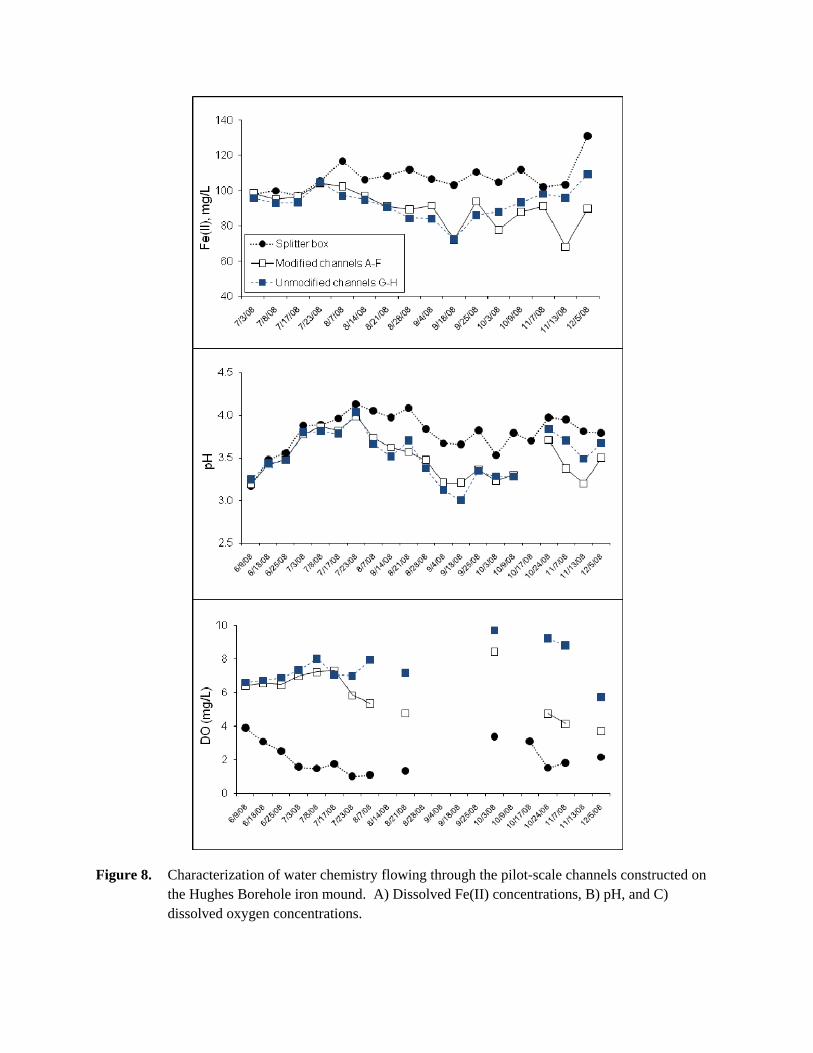
Figure 8. Characterization of water chemistry flowing through the pilot-scale channels constructed on the Hughes Borehole iron mound. A) Dissolved Fe(II) concentrations, B) pH, and C) dissolved oxygen concentrations.

Figure 9. Fe(II) oxidation kinetics measured in laboratory batch experiments using non-sterile site water from Hughes Borehole.

18
Flow-through “gutter” reactor experiments were used to determine what minimum hydraulic
residence time is required for low-pH Fe(II) oxidation and subsequent Fe(III) precipitation to provide
effective treatment for AMD. These experiments were begun at a hydraulic residence time of 10 h and a
several day lag period was observed before effective Fe removal began (Figure 10A). After a pseudo-
steady state condition had been achieved where the [Fe(II)]out/[Fe(II)]in ratio had stabilized and remained
relatively constant for multiple residence times, the flow rate was increased to evaluate how the system
would function at a shorter residence time. This sequential, incremental decrease in hydraulic residence
time was continued until the gutter reactors failed to remove Fe. The Fe(II) removal efficiency was
calculated from the pseudo-steady state conditions and are plotted versus hydraulic residence time in
Figure 11. Based on these results we have concluded that a minimum residence time of 120 min will be
required to promote natural low-pH Fe(II) oxidation in the field.
6.3 Sediment Characterizations
Sediment samples collected from different depositional facies on the mound, e.g. channels, pools,
terraces and meanders, displayed relatively similar mineralogical characteristics based on XRD (Figure
12). However, we found more biological features in sediments collected from slower flowing facies, e.g.
pools and meanders, as compared to the faster flowing channels based on images obtained by scanning
electron microscopy (SEM) (Figure 13).
7. Assessment of Proposed Objectives
In December 2006, we submitted the corresponding proposal for this project to the
Commonwealth of Pennsylvania’s Department of Environmental Protection (DEP) Bureau of Abandoned
Mine Reclamation (BAMR) in response to their Request for Proposals for “Innovative Mine Drainage In-
Situ or Ex-Situ Treatment or Abatement, or Enhanced Metals Recovery”, RFP No. OSM PA(AMD-06).
The original objectives of our proposal were to: 1) evaluate the use of biological low-pH Fe(II) oxidation
in natural or manipulated settings for the passive pretreatment of high flow AMD discharges (> 250
gpm); 2) develop a design equation that can be used to size aeration terraces for low-pH Fe(II) oxidation;
3) develop a standardized laboratory protocol to measure the potential rate of low-pH Fe(II) oxidation for
any field site; and 4) study the microbial communities and mineralogy associated with low-pH Fe(II)
oxidation in order to fully exploit this process for pretreatment purposes. We will address each of these
objectives below.
1) Evaluate the use of biological low-pH Fe(II) oxidation in natural or manipulated settings for
the passive pretreatment of high flow AMD discharges (> 250 gpm). We have accomplished this
objective through our one year field monitoring of the Hughes Borehole and the laboratory “gutter”
reactor experiments we conducted with Hughes Borehole sediments. For coarse unit-sizing, we estimate
that natural low-pH iron terraces can remove 0.5 to 5 g Fe d-1 m-2 (GDM). In comparison, design
guidelines for iron removal from net-acid coal mine drainage using aerobic wetlands range from 2 to 5
GDM.

19
2) Develop a design equation that can be used to size aeration terraces for low-pH Fe(II)
oxidation. We have not yet accomplished this objective. While we can and have measured rates of Fe(II)
oxidation in controlled laboratory experiments, we cannot yet transfer these kinetic data to field settings.
One major obstacle to meeting this objective is that we do not yet fully understand the interplay between
microbial activity, water velocity, and water column depth. Another major obstacle is that hydrodynamic
conditions across these iron mounds can be very heterogeneous and exhibit behavior that is far from an
idealized chemical reactor such as a plug flow reactor. We will continue to work on this objective in the
future, beyond the life of this grant.
3) Develop a standardized laboratory protocol to measure the potential rate of low-pH Fe(II)
oxidation for any field site. We have accomplished this objective through our development of “gutter” and
“chunk” reactors. We propose that the procedures detailed in section 4 above would best serve as the
standardized protocol.
4) Study the microbial communities and mineralogy associated with low-pH Fe(II) oxidation in
order to fully exploit this process for pretreatment purposes. We have accomplished this objective
through the use of DNA-based techniques to characterize the microbial communities found across these
iron mounds, and through the use of XRD and SEM to characterize the iron mound minerals. With
respect to the microbial communities, we have found that they change primarily as a function of pH. At a
typical low-pH iron mound, a Euglena-dominated community is present at the emergent anoxic spring,
then a Betaproteobacteria (primarily Ferrovum spp.)-dominated community is present at the upstream end
of the iron mound (across pH 3.5 to 3.0 portion of mound), and then a Gammaproteobacteria (primarily
Acidithiobacillus)-dominated community is present at the downstream end of the iron mound (across
portion of mound where pH drops to 2.5). With respect to the mineralogy, schwertmannite was found to
be the predominant mineral phase precipitated at all iron mounds studied. Schwertmannite particles
occurred as micron sized spheroids with characteristic “hedgehog” morphology at all sites. No trace
metal incorporation was detected in sediments from the field sites, and no metals (other than Fe) were
removed from the AMD at any of the field sites.

20
8. Conclusions The major conclusions from the research presented in this thesis which can be applied to
constructing a passive treatment reactor are summarized in the following list: Biological Fe(II) oxidation occurs at Hughes Borehole and can be enhanced by
modifications to the existing iron mound. However, there is variability in both the quantity and quality of AMD from the emergent discharge and variability in the natural biological and chemical processes occurring across the iron mound.
An acclimation period of 300-450 hours was necessary for the treatment reactors to reach steady state. After this period, residence times of at least 5 and 10 hours were needed to oxidize 90% and 97% of the influent Fe(II), respectively.
The dissolved Fe(II) oxidation efficiency of reactors with iron mound sediments improved with age of the sediments until approximately 90 days. Fe(II) oxidation efficiencies for 1 and 2 hour residence times ranged from 25-60%, and 60-80%, respectively, as the sediments aged. This suggests that biological communities continue to develop over time and can improve the efficiency of the reactors as the age of the sediments increase.
Total Fe percent remaining were consistently 20-30% greater than Fe(II) percent remaining for each residence time. Even though more Fe(OH)3 precipitated during longer residence times the relative percentage of Fe(II) to total Fe stayed the same for each residence time.
The effluent end of the gutter reactors had pH values of 2.5 to 3.0, with influent pH values of 3.0 to 4.0, even after the majority of Fe(II) was oxidized. The effluent pH values stayed reasonably constant for specific residence times despite the variation of Fe(II) oxidation efficiency during the acclimation of each residence time.
The gutter reactors that contained iron mound sediment had much greater Fe(II) oxidation efficiencies (25-97%) than reactors that only contained AMD (0-10%). This suggests that iron mound sediments greatly improve the Fe(II) oxidation efficiency.
No other dissolved metals besides Fe were removed from the AMD at Hughes Borehole or in the laboratory-scale gutter reactors. The iron mound sediment consisted of approximately 65-75% iron oxide solids and 25-35% volatile solids.
Additional surface area, (i.e. plastic media or coconut fiber), increased the Fe(II) oxidation efficiency of the reactors even at relatively short residence times of 10-60 minutes.
Regardless of the type of treatment in the on-mound reactors, increased residence time resulted in increased Fe(II) oxidation efficiency. Furthermore, the on-mound reactors were more effective than the laboratory reactors at oxidizing dissolved Fe(II) at short residence times.
Fe(II) oxidation rates from the gutter reactors with iron mound sediments ranged from 4.67 x 10⁻⁸ M/s to 3.24 x 10⁻⁷ M/s, or 0.16 mg/L-min to 1.1 mg/L-min. These values are very similar to published biological Fe(II) oxidation rates.

Figure 10. Fe(II) oxidation measured in laboratory flow-through “gutter” reactor experiments using Hughes Borehole iron mound sediments. A) Effluent concentrations of Fe(II) normalized to corresponding influent concentrations of Fe(II), B) pH, and C) dissolved oxygen concentrations versus number of pore volumes (PVs) of reactor operation. Channels 1 and 2 were duplicate gutters that contained no sediment, while channels 3 and 4 were duplicate gutters that contained iron mound sediments. A 10 h residence time was maintained from 0 to 31 PVs, a 5 h residence time was maintained from 33 to 97 PVs, a 2 h residence time was maintained from 100 to 143 PVs, and a 1 hour residence time was maintained from 144 to 176 PVs.

Figure 11. Effect of hydraulic residence time on the removal efficiency of A) Fe(II), and B) total Fe based on flow-through “gutter” reactor experiments conducted with Hughes Borehole iron mound sediments.

Figure 12. X-ray diffraction patterns from sediments collected from the top 2 cm from various locations across the Hughes Borehole iron mound. The upper black line is from a shallow terrace, the middle red line is from the main channel, and the lower blue line is from the bottom of a shallow pool. Reference powder diffraction files for Schwertmannite and Goethite are included for comparison.
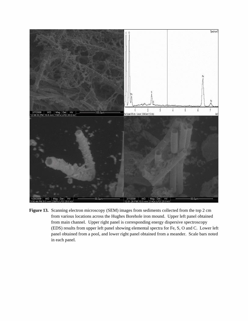
Figure 13. Scanning electron microscopy (SEM) images from sediments collected from the top 2 cm from various locations across the Hughes Borehole iron mound. Upper left panel obtained from main channel. Upper right panel is corresponding energy dispersive spectroscopy (EDS) results from upper left panel showing elemental spectra for Fe, S, O and C. Lower left panel obtained from a pool, and lower right panel obtained from a meander. Scale bars noted in each panel.