AEN-140: Constructing a Platform Alley Scale System · dent of the head gate or cattle chute. This...
6
Cooperative Extension Service | Agriculture and Natural Resources | Family and Consumer Sciences | 4-H Youth Development | Community and Economic Development University of Kentucky College of Agriculture, Food and Environment Cooperative Extension Service AEN-140 Constructing a Platform Alley Scale System Josh Jackson, Biosystems and Agricultural Engineering M ost producers would like informa- tion on cattle weight to improve management. The widespread use of cattle scales on most farms in Kentucky is limited by the cost of purchasing the equipment. Local cattlemen’s asso- ciations or extension offices frequently have scale systems that can be rented or borrowed. However, renting or bor- rowing has challenges due to scheduling conflicts, reliability, and rental fees. Ad- ditionally, the scale may not align with the handling facility layouts. ere are two options for producers to obtain cattle weights—in the alley or at the chute. An alley scale provides the ability to measure cattle weight indepen- dent of the head gate or cattle chute. is publication describes the measurement of cattle in the alley leading to a head gate or cattle chute. A future publication will discuss integrating a weigh system with a squeeze chute. One advantage of a platform scale is portability as the platform could be more easily moved to different locations or farms. Another advantage is that the platform scale allows the producer to know the animal’s weight prior to it enter- ing the chute. e limitation of weighing in the alley is that excitable animals can- not be properly restrained or squeezed. Furthermore, there will be an additional cost associated with adding alley gates to hold the animal on the scale. Table 1. Cost of overapplying dewormer and antibiotics. Pounds OVERestimated Actual Weight Cost ($)/head Dewormer 1 Antibiotic 2 25 $0.20 - 0.38 $0.18 - 1.14 50 $0.41 - 0.76 $0.36 - 2.29 75 $0.61 - 1.15 $0.54 - 3.43 100 $0.82 - 1.52 $0.72 - 4.57 1 Cost range based upon Pour-On, injectable, and LongRange dewormer. 2 Cost range based upon cost of 500 ml of Noromycin 300 LA Oxytetracycline (Norbrook Labs) and Draxxin Tulathromyicn (Zoetis Animal Health). Importance of Obtaining Weights Accurately obtaining cattle weights is an essential part of managing a beef operation. Administration of antibiotics and dewormer as well as purchasing and selling of cattle is done on a weight (or per pound) basis. e underapplication of antibiotics could lead to treatment failure. Underapplication of dewormer can lead to reduced performance char- acteristics such as: average daily gains, milk production, and conception rates. Conversely, overapplication can be costly (Table 1). Scale Types When considering commercially available scales, there are three differ- ent types of scales: mechanical beam, hydraulic, and load cells/load bars. For mechanical beam scales, the animal’s weight is transferred to a balance beam and read by adjusting the location and amount of mass on the beam so that the beam’s pointer is horizonal. Hydraulic scales transfer the weight of the animals through a fluid medium to a dial that is then read. Most common today are scales based on load cells or load bars. A load bar typically has two load cells integrated into the bar. Load cells measure the force and transmit an electrical signal to a digital read out. While there are inher- Figure 1. Different scale types Mechanical Hydraulic Load Cell/Bar
Transcript of AEN-140: Constructing a Platform Alley Scale System · dent of the head gate or cattle chute. This...

Cooperative Extension Service | Agriculture and Natural Resources | Family and Consumer Sciences | 4-H Youth Development | Community and Economic Development
University of KentuckyCollege of Agriculture,Food and EnvironmentCooperative Extension Service
AEN-140
Constructing a Platform Alley Scale System Josh Jackson, Biosystems and Agricultural Engineering
Most producers would like informa-tion on cattle weight to improve
management. The widespread use of cattle scales on most farms in Kentucky is limited by the cost of purchasing the equipment. Local cattlemen’s asso-ciations or extension offices frequently have scale systems that can be rented or borrowed. However, renting or bor-rowing has challenges due to scheduling conflicts, reliability, and rental fees. Ad-ditionally, the scale may not align with the handling facility layouts. There are two options for producers to obtain cattle weights—in the alley or at the chute. An alley scale provides the ability to measure cattle weight indepen-dent of the head gate or cattle chute. This publication describes the measurement of cattle in the alley leading to a head gate or cattle chute. A future publication will discuss integrating a weigh system with a squeeze chute. One advantage of a platform scale is portability as the platform could be more easily moved to different locations or farms. Another advantage is that the platform scale allows the producer to know the animal’s weight prior to it enter-ing the chute. The limitation of weighing in the alley is that excitable animals can-not be properly restrained or squeezed. Furthermore, there will be an additional cost associated with adding alley gates to hold the animal on the scale.
Table 1. Cost of overapplying dewormer and antibiotics.
Pounds OVERestimated Actual Weight
Cost ($)/head
Dewormer1 Antibiotic2
25 $0.20 - 0.38 $0.18 - 1.1450 $0.41 - 0.76 $0.36 - 2.2975 $0.61 - 1.15 $0.54 - 3.43100 $0.82 - 1.52 $0.72 - 4.571 Cost range based upon Pour-On, injectable, and LongRange dewormer.
2 Cost range based upon cost of 500 ml of Noromycin 300 LA Oxytetracycline (Norbrook Labs) and Draxxin Tulathromyicn (Zoetis Animal Health).
Importance of Obtaining Weights Accurately obtaining cattle weights is an essential part of managing a beef operation. Administration of antibiotics and dewormer as well as purchasing and selling of cattle is done on a weight (or per pound) basis. The underapplication of antibiotics could lead to treatment failure. Underapplication of dewormer can lead to reduced performance char-acteristics such as: average daily gains, milk production, and conception rates. Conversely, overapplication can be costly (Table 1).
Scale Types When considering commercially available scales, there are three differ-ent types of scales: mechanical beam, hydraulic, and load cells/load bars. For mechanical beam scales, the animal’s weight is transferred to a balance beam
and read by adjusting the location and amount of mass on the beam so that the beam’s pointer is horizonal. Hydraulic scales transfer the weight of the animals through a fluid medium to a dial that is then read. Most common today are scales based on load cells or load bars. A load bar typically has two load cells integrated into the bar. Load cells measure the force and transmit an electrical signal to a digital read out. While there are inher-
Figure 1. Different scale types
Mechanical Hydraulic Load Cell/Bar

2
Figure 2. Platform alley scale.
Figure 3. Cut length for steel channel and boards.
Figure 4. Cutting of metal.
Figure 5. Location of holes for the different sections of steel channel.
Side Channel
End Channel
Interior Channel

3
ent tradeoffs with the different types of scales, load cells are very common due to their relative low cost and high accuracy. Digital readouts could be integrated with electronic identification systems and farm management software.
Alternative The alternative to commercially avail-able scale systems is to build a platform alley scale system. Six main materials are required for the construction of a platform alley scale: load cell kit, C5 x 6.7 (in. x lb/ft) steel channel (commonly referred to as 5 in. C-channel steel), 1 x 1 x 1/8 in. steel angle, 2 in. x 8 in. rough cut or pressure treated lumber, fasten-ers (bolts, nuts, washers, staples), and cattle feedlot fence panel-4 gauge wire (commonly referred to as hog panel). Searching ecommerce sites with the criteria “livestock scale kit” will reveal a wide range scale kits. The kit used in this publication included four 5,000 lb load cells (20,000 lb total capacity), four mounting blocks, four spacers, a display, 110 volt connection, battery power, and associated fasteners, at a cost that was under $400. The other materials needed can be obtained from local businesses.
Building a Scale System Step 1: Create a Level Surface The location of the planned scale is ultimately dependent upon the current layout of the facilities and if the scale system is going to be permanently fixed in a location or if it needs to be portable. A platform alley scale system could be transported between farms. No matter what system is obtained and built, a level and firm surface is re-quired to ensure accuracy of the readings. Concrete pads are recommended for the scale location and the surrounding area. The thickness of the pad must be a minimum of 4 in., but it is recommended that it be designed thicker (6 in.) if heavy equipment (trucks, skid steers, or trac-tors) is going to be run across the pad. AEN-115: All-Weather Surfaces for Livestock goes into some of the details associated with the pressures that cattle can create on surfaces.
Figure 6. Location of holes for mid and end boards.
Mid Boards
End Boards
Step 2: Cut Metal and Boards to Specified Length During construction of the platform scale, be sure to wear the appropriate personal protective equipment such as: safety glasses, ear plugs, gloves, etc. The platform alley scale was designed to be 88 in. x 24 in. (length x width). This design should work on most operations. If necessary, the width could be altered slightly to match the dimensions of the alley. Nonetheless, the following recom-mendations in this publication are based upon the assumption that 24 in. is used as the width. Using C5 x 6.7 steel channel, cut two 88 in. long sections and three 14 in. long sections shown in Figure 3. If possible, these could be cut at the place of purchase. Options for cutting on-farm
include a grinder with cutting wheel, chop saw, or band saw (Figure 4). For the rough cut 2 in. x 8 in. lumber, 10 sec-tions that are 24 in. in length are needed (Figure 3), and these boards can be cut using a circular saw or table saw.
Step 3: Drill Holes in Steel Channel and Boards The location of the 17/32 in. holes for the two long steel side channels is shown in Figure 5. In addition to the holes that will be used to hold the boards along the web (wide part of the channel) a single 17/32 hole should be centered in the flange (the 1 ¾ in. portion) to run the wires through. Be sure to install a grommet to protect the wires from the sharp steel edges. The two small end channels each
Figure 7. Weld mounting block to side channels (left and right). Red highlighted region indicates weld.

4
Figure 9. Steel angle welded to scale frame. Red highlight indicates weld.
Figure 10. Arrow points away from feet of load cell. Spacer block is shown on top of load cell (red arrow).
require two—17/32 in. holes to be drilled for holding the end boards. The third small channel used in the interior requires a 17/32 in. hole drilled into the flange con-necting the wires to the junction box. Mark the desired location of the holes and use a center punch prior to drilling. Drilling this number of holes would be most easily performed with a drill press, perhaps where the steel is purchased. Drilling could be done at the farm using a handheld drill but would be difficult.
Boards Of the ten rough sawn lumber boards, eight will be designated as mid boards with the hole pattern shown in Figure 6. Due to the planned location of the load cells, the end boards possess a different hole pattern from the mid boards (Figure 6).
Step 4: Weld Mounting Block to Side Channels Within the kit, there should be four threaded mounting blocks. Weld each individual mounting block 3 and 27/32 in. from each end of the 88 in. side channels
(both left and right) as shown in Figure 7. Do not weld on or around the load cells as this will destroy them.
Step 5: Weld Steel Channel and Add Conduit As shown in Figure 8, the side channel sections will be aligned parallel, and their orientation is important as the holes in the flange of the side channel must be fac-ing toward each other for running wires in the later steps. The end channel will be placed between the side channels and should be flush with both ends of the side channel respectively. The interior chan-nel should be centered to the midpoint of the side channel. The orientation of the interior channel’s flange hole does not matter as the unit will be symmetrical. Once again, do not weld on or around load cell as this will destroy them.Conduit would also be welded to the frame at this time to protect the wires. Steel angle (1 x 1 x 1/8 in.) was used in this case, but pipe or tubing could be used (Figure 9). A nominal length of 30 in. was used for each section of angle. Wire will be run to the center of the scale using
each one of these steel angle sections. Avoid using galvanized conduit since welding on this material can create toxic fumes. After welding is complete, prime and paint the steel assembly to limit rust.
Step 6: Attach Load Cells to Mounting Block and Boards to Steel Channel Orientation of the load cells is impor-tant. Make certain that the arrow on the load cell is pointing away from the feet and toward the “load” or weight of the chute (Figure 10). A spacer block, also included in the kit, is used to ensure that the load cell has enough space to deflect with the additions of loads. The fasteners for attaching the load cells are included in the kit. See Figure 11 for a detailed description of how to secure the load cell. For the eight mid and two end boards, use the UNC carriage bolts (½ -13 x 2.5 in.) to securely attach the boards to the steel channel frame (Figure 12). Secure the cattle panel (4-gauge wire) to the top of the boards using several staples.
Step 7: Run Wires from Load Cells and Display to Junction Box Each load cell includes approximately 20 feet of cord. Going directly from the load cells, feed the load cell wires through the nearest conduit 1 x 1 x 1/8 in. steel angle (Figure 13). The flange holes in the
Figure 8. Weld the steel channels together with the two side steel channel section parallel (flange holes facing each other) and the 14” C-channel sections at each end and in the interior. Red highlight indicates weld.

5
Figure 11. View from the bottom of how to attach the load cell to the mounting block.
Figure 12. Attach the end and mid boards as shown. For differentiation purposes, the two end boards in the drawing are represented in the reddish-brown color.
side channel are used to route the wires for each side into the interior channel. Subsequently, the wires are threaded through the interior channel flange hole and into the space below the lumber. Now the wires can be inserted into the junction box openings. Several different iterations of the junction box could be included with the load cell kits. Nonethe-less for most kits, the junction box will still contain four screw terminal blocks dedicated to the load cells and one screw terminal block designated to the weight indicator (display). Each of the load cells and display wire possess five individual wires within the bundle, and an example of the wiring within the junction box is shown in Figure 14. Follow instructions provided by the manufacturer for wiring instructions as the wire colors may have been altered.
Step 8: Attach Junction Box to Scale Platform To improve portability, the junction box can be attached to the lower side of the platform scale (Figure 15). The extra wire from each load cell was collected and attached to the bottom of the lumber using cable clamps (Figure 16). Cutting the wire down is not recommended as this would change the resistance of the wires and potentially the electronic signal going to the junction box. If the platform scale is going to be in a fixed location the junction box could be attached adjacent to the alley. The weight indicator (dis-play) includes a mounting bracket, and the bracket can be attached to the alley or adjacent location. The display can be powered using a standard 110 volt power supply or internal battery. The display possesses a quick disconnect from the junction box cord which makes the display easy to store away in a safe place when not in use.
Step 9: Calibration For the load cell kit used, calibration is performed by the user. Conduct the cali-bration per the scale system guidelines. Calibration of the scale system is a very important step as this will determine how accurate and precise the system will be. Most scales will use the simplest calibra-tion which involves a two-point system. The two-point system uses a zero and known weight calibration. The zero cali-
Figure 13. View from the bottom of the scale demonstrates how to the route the wires from the respective load cells to the junction box. Each wire associated with a load cell is indicated using a different color in this drawing. The dotted lines represent running the wires into the steel angle conduit. The stars indicate the wiring from the display to the junction box. On each side channel, the wires are run through the flange hole into the interior channel. From the interior channel, the wires are passed through the flange hole and run into the junction box. If the scale is going to remain in a constant location, the display wire could be run throughout conduit and attached to the floor or adjacent wall.
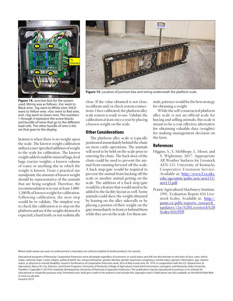
Figure 14. Junction box for the system used. Wiring was as follows: -Exc went to Black wire; -Sig went to White wire; SHLD went to Yellow wire; +Exc went to Red wire, and +Sig went to Green wire. The numbers 1 through 4 represent the screw blocks and bundle of wires that go to the different load cells. The other bundle of wire is the set that goes to the display.
Figure 15. Location of junction box and wiring underneath the platform scale.
bration is when there is no weight upon the scale. The known weight calibration utilizes a user specified addition of weight to the scale for calibration. The known weight added could be mineral bags, feed bags, tractor weights, a known volume of water, or anything else in which the weight is known. From a practical use standpoint, the amount of known weight should be representative of the animals that are being weighed. Therefore, the recommendation is to use at least 1,000-1,200 lb of known weight for calibration.Following calibration, the next step would be to validate. The simplest way to check the calibration is to step on the platform and see if the weight obtained is expected, a hard truth, or not realistically
Educational programs of Kentucky Cooperative Extension serve all people regardless of economic or social status and will not discriminate on the basis of race, color, ethnic origin, national origin, creed, religion, political belief, sex, sexual orientation, gender identity, gender expression, pregnancy, marital status, genetic information, age, veteran status, or physical or mental disability. Issued in furtherance of Cooperative Extension work, Acts of May 8 and June 30, 1914, in cooperation with the U.S. Department of Agriculture, Nancy M. Cox, Director, Land Grant Programs, University of Kentucky College of Agriculture, Food and Environment, Lexington, and Kentucky State University, Frankfort. Copyright © 2019 for materials developed by University of Kentucky Cooperative Extension. This publication may be reproduced in portions or its entirety for educational or nonprofit purposes only. Permitted users shall give credit to the author(s) and include this copyright notice. Publications are also available on the World Wide Web at www.ca.uky.edu.Issued 6-2019
close. If the value obtained is not close, recalibrate and/or check system connec-tions. Once calibrated, the platform alley scale system is ready to use. Validate the calibration at least once a year by placing a known weight on the scale.
Other Considerations The platform alley scale is typically positioned immediately behind the chute on most cattle operations. The animals will need to be held on the scale prior to entering the chute. The back door of the chute could be used to prevent the ani-mal from running forward off the scale. A back stop/gate would be required to prevent the animal from backing off the scale or another animal getting on the scale. The addition of a back stop/gate would be a feature that would need to be added to the facility layout as well. Some animals could skew the weight obtained by leaning on the alley sidewalls or by placing a portion of their weight on the gate immediately in front or behind them while they are on the scale. For these ani-
mals, patience would be the best strategy for obtaining a weight While the self-constructed platform alley scale is not an official scale for buying and selling animals, this scale is meant to be a cost-effective alternative for obtaining valuable data (weights) for making management decision on the farm.
ReferencesHiggins, S., S. Mehlhope, L. Moser, and
S. Wightman. 2017. Appropriate All Weather Surfaces for Livestock AEN-115. University of Kentucky Cooperative Extension Service. Available at: http://www2.ca.uky.edu/agcomm/pubs/aen/aen115/aen115.pdf.
Prairie Agricultural Machinery Institute. 1991. Evaluation Report 654 Live-stock Scales. Available at: http://pami.ca/pdfs/reports_research_updates/(5e)%20Livestock%20Scales/654.PDF.
Where trade names are used, no endorsement is intended, nor criticism implied of similar products not named.