AECOsim Building Designer Architecture - Parametric Cell ......AECOsim Building Designer...
94
AECOsim Building Designer Architecture - Parametric Cell Studio V8i (metric) SELECTseries 3 Bentley Institute Course Guide TRN019360-1/0001
Transcript of AECOsim Building Designer Architecture - Parametric Cell ......AECOsim Building Designer...

TRN019360-1/0001
AECOsim Building Designer Architecture - Parametric Cell StudioV8i (metric) SELECTseries 3
Bentley Institute Course Guide

Trademarks
AccuDraw, Bentley, the “B” Bentley logo, MDL, MicroStation and SmartLine are registered trademarks; PopSet and Raster Manager are trademarks; Bentley SELECT is a service mark of Bentley Systems, Incorporated or Bentley Software, Inc.
AutoCAD is a registered trademark of Autodesk, Inc.
All other brands and product names are the trademarks of their respective owners.
Patents
United States Patent Nos. 5, 8.15,415 and 5,784,068 and 6,199,125.
Copyrights
©2000-2012 Bentley Systems, Incorporated. MicroStation ©1998 Bentley Systems, Incorporated. All rights reserved.
AECOsim Building Designer Architecture - Parametric Cell Studio 2 Nov-12Copyright © 2012 Bentley Systems, Incorporated

Nov-12Studio
Table of Contents
Course Overview ____________________________________ 5Course Description ____________________________________5Target Audience_______________________________________5Prerequisites _________________________________________5Course Objectives _____________________________________5Modules Included _____________________________________6
Background Information on Parametric Cell Studio ________ 7Module Overview _____________________________________7Module Prerequisites __________________________________7Module Objectives_____________________________________7Starting PC Studio _____________________________________8PC Studio User Interface ________________________________9Working with Existing Files ______________________________10Creating and Saving a New File ___________________________11Tool Basics ___________________________________________13
2D Path and Constraints ______________________________ 15Module Overview _____________________________________15Module Prerequisites __________________________________15Module Objectives_____________________________________15The 2D Path __________________________________________16Path2d Key-in Options__________________________________30
Variables and Named Dimensions ______________________ 33Module Overview _____________________________________33Module Prerequisites __________________________________33Module Objectives_____________________________________33Adding Variables ______________________________________34Creating Variables _____________________________________36Named Dimensions ____________________________________37
Door Components ___________________________________ 39Module Overview _____________________________________39Module Prerequisites __________________________________39
3 AECOsim Building Designer Architecture - Parametric Cell
Copyright © 2012 Bentley Systems, Incorporated
AECOsim Building
Table of Contents
Module Objectives_____________________________________39Creating Components __________________________________40Placing a Component___________________________________42Creating an Auto Component ____________________________44Loading a Component Library ____________________________52Assembling Components ________________________________54Substituting Components _______________________________57Positioning Key-in Options ______________________________58
Publishing to AECOsim Building Designer Architecture _____ 61Module Overview _____________________________________61Module Prerequisites __________________________________61Module Objectives_____________________________________61Publishing Components_________________________________62
Path Offest _________________________________________ 65Module Overview _____________________________________65Module Prerequisites __________________________________65Module Objectives_____________________________________65Create an Offset Path __________________________________66Placing a Path Component ______________________________69Creating a Perpendicular Offset Copy of a Path ______________71
Window Components ________________________________ 73Module Overview _____________________________________73Module Prerequisites __________________________________73Module Objectives_____________________________________73Creating an Auto Component ____________________________74Simple Extrusion ______________________________________75
Component Array ___________________________________ 83Module Overview _____________________________________83Module Prerequisites __________________________________83Module Objectives_____________________________________83Create an Array Along a Path ____________________________84Activate an Array for Editing _____________________________87Create an Array Along a Path ____________________________90
Designer Architecture - Parametric Cell Studio 4 Nov-12Copyright © 2012 Bentley Systems, Incorporated

Course Overview
Course Description
This Parametric Cell Studio (PC Studio) course will serve as an introductory workshop to convey the concepts of PC Studio and get the first insight into how to create and implement parametric cells within an organization's implementation of AECOsim Building Designer.
Target Audience
This course is designed for students new to the PC Studio software.
Prerequisites
The student needs to have a fundamental knowledge of parametric cell requirements and a working knowledge of 3D design. Experience with Bentley Building products is an advantage.
Course Objectives
After completing this course, you will be able to:
• Create named dimensions and constraints.
• Publish the cells to AECOsim Building Designer Architecture.
• Create parametric doors and windows.
• Use 2d path and constraints.
• Use component array as a method of placement.
Nov-12 5 Course Overview
Copyright © 2012 Bentley Systems, Incorporated

Modules Included
Modules Included
The following modules are included in this course:
• Background Information on PC Studio
• 2d Path and Constraints
• Named Dimensions and Variables
• Door Components
• Publishing to AECOsim Building Designer Architecture
• Path Offset
• Window Components
• Component Array
Course Overview 6 Nov-12Copyright © 2012 Bentley Systems, Incorporated
Background Information on Parametric Cell Studio
Module Overview
This lesson will introduce you to the concept of PC Studio and will cover the first step when starting with a PC Studio session.
Module Prerequisites• Fundamental knowledge of parametric cell requirements.
• Working knowledge of 3D design.
Module Objectives
After completing this module, you will be able to:
• Start PC Studio.
• Use the PC Studio User Interface.
• Open and create PC Studio files.
• Understand Tool basics.
Nov-12 7 Background Information on Parametric Cell Studio
Copyright © 2012 Bentley Systems, Incorporated

Starting PC Studio
Starting PC Studio
Studio can be started from the Bentley Designer> Parametric Cell Studio or from the desktop shortcut icon (if added to the desktop).
Note: The Family and Parts available will be determined by the User and Project selected when initializing AECOsim Building Designer Architecture.
Background Information on Parametric Cell Studio 8 Nov-12Copyright © 2012 Bentley Systems, Incorporated
PC Studio User Interface
PC Studio User Interface
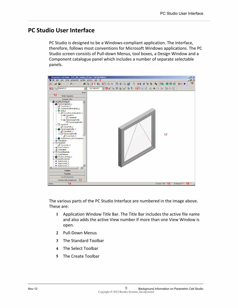
PC Studio is designed to be a Windows-compliant application. The interface, therefore, follows most conventions for Microsoft Windows applications. The PC Studio screen consists of Pull-down Menus, tool boxes, a Design Window and a Component catalogue panel which includes a number of separate selectable panels.
The various parts of the PC Studio Interface are numbered in the image above. These are:
1 Application Window Title Bar. The Title Bar includes the active file name and also adds the active View number if more than one View Window is open.
2 Pull-Down Menus
3 The Standard Toolbar
4 The Select Toolbar
5 The Create Toolbar
Nov-12 9 Background Information on Parametric Cell StudioCopyright © 2012 Bentley Systems, Incorporated

Working with Existing Files
6 The Component Toolbar
7 The Region Toolbar
8 The Utilities Toolbar
9 The Current Properties Settings box
10 The View Toolbar
11 The Named Views Toolbar
12 The Component Catalog Window (Docked). The Container View is open showing a Tree View of the model contents.
13 This Tab in the Component Catalog indicates a loaded Component Library
14 The Status Bar. This includes the message area to the Left and the snap settings to the Right.
15 The active Angle Snap Status. Double-click this area to open the Snap/Edit Settings tab on the Options Dialog.
16 The active Distance Snap Status. Double-click this area to open the Snap/Edit Settings tab on the Options Dialog.
17 The design View Window (Maximized). Any number of View Windows can be opened simultaneously and maximized, cascaded or tiled.
18 View Window controls for a maximized View window Opening and Creating PC Studio Files.
Working with Existing Files
Existing Files are opened in the same way as any other Windows-based program, that is, from the menus, you can choose File > Open or select the Open File Icon on the Standard toolbar.
PC Studio uses two File extensions. These are *.pac and *.paz, the latter of which is used for published files. Files with both extensions can be opened in PC Studio.
Background Information on Parametric Cell Studio 10 Nov-12Copyright © 2012 Bentley Systems, Incorporated

Creating and Saving a New File
Creating and Saving a New File
Exercise: Create and Save a New File
In this exercise, you will create a new file, change some settings, and save it under a new name.
1 From the Standard Toolbar, choose the New File Icon.
Note: :If File > New is used, there will then be a prompt to select a seed file other than the default seed.
2 From the Tools menu, choose Options.
Nov-12 11 Background Information on Parametric Cell StudioCopyright © 2012 Bentley Systems, Incorporated

Creating and Saving a New File
3 In the Options Dialog, select the Units tab and choose Millimeters.
4 Click OK, and the Distance snap setting will change to 304.8mm.
5 Double-click on the D Snap: field in the Status bar at the bottom right of the PC Studio window.
6 The Options dialog opens, with the current Distance Snap value selected.
7 Enter 50mm and click OK.
8 Double-click on the A Snap or D Snap: fields in the Status bar. This is a different way to get to the Options dialog.
Background Information on Parametric Cell Studio 12 Nov-12Copyright © 2012 Bentley Systems, Incorporated

Tool Basics
9 In the Options dialog, choose the Path Preferences tab. Set the Default Left and Right Width to 0.0mm and the Path Increment Snap to 10mm, as shown below.
This panel defines the default width of a path, left and right of the work-line, and the increment to step by when the path width is changed dynamically during placement using the arrow keys.
10 Click OK.
11 Choose the Save Icon or the File > Save As menu option.
12 In the Save As dialog, navigate to the following directory: C:\PCStudio_Training\
13 Enter the file name 00_NewFile, and click the Save button. The default extension .pac will be added to the file name.
Tool Basics
These procedures are the same for all the Tools (Commands) in PC Studio:
• You activate a Tool by choosing it from the Menu or from a Toolbar with the <Left Mouse Button>.
• To complete a Tool, press the <Enter> key.
• To cancel a Tool, press the <Esc> key.
• When the current tool is creating or modifying geometry (e.g. the Path2d Tool), the <Esc> key will abort the operation.
• For many of the view manipulation tools, the <Esc> key will return control to a suspended tool (e.g. Positioning a Component).
Nov-12 13 Background Information on Parametric Cell StudioCopyright © 2012 Bentley Systems, Incorporated

Tool Basics
Background Information on Parametric Cell Studio 14 Nov-12Copyright © 2012 Bentley Systems, Incorporated

2D Path and Constraints
Module Overview
In this lesson, you will take a look at the specifics of the Dimension Driven Path. This is always the starting point for any parametric object you want to build with PC Studio.
Module Prerequisites• Starting PC Studio.
• Using the PC Studio User Interface.
• Opening and creating PC Studio files.
Module Objectives
After completing this module, you will be able to:
• Create and modify a 2D Path element.
• Use shortcut keys.
Nov-12 15 2D Path and Constraints
Copyright © 2012 Bentley Systems, Incorporated

The 2D Path
The 2D Path
The Dimension Driven path (Path2d) Tool is used to create all forms of path objects within PC Studio and is therefore the starting point for all elements in PC Studio. A Path2d is defined as a connected set of line and arc segments, which may be wide or have zero-width (a single edge). The Path2d is often the initial model object created for a number of operations. A solid understanding of the Path2d Object in PC Studio is vital to successful Cell creation. This element is called a Dimension Driven Path rather than a line-string or shape, because it has dimensional constraints that makes it more intelligent than a simple shape.
Exercise: Creating a Path2d Element
In this exercise, you will create and modify a simple Path2d Object to match the profile shown below.
2D Path and Constraints 16 Nov-12Copyright © 2012 Bentley Systems, Incorporated
The 2D Path
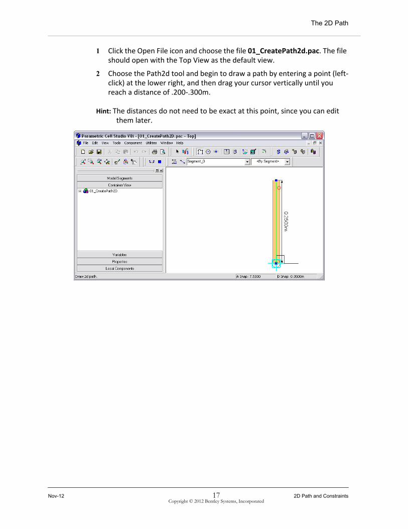
1 Click the Open File icon and choose the file 01_CreatePath2d.pac. The file should open with the Top View as the default view.
2 Choose the Path2d tool and begin to draw a path by entering a point (left-click) at the lower right, and then drag your cursor vertically until you reach a distance of .200-.300m.
Hint: The distances do not need to be exact at this point, since you can edit them later.
Nov-12 17 2D Path and ConstraintsCopyright © 2012 Bentley Systems, Incorporated

The 2D Path
3 The path needs to be a 0 width path. Press the down arrow key twice to reduce the path width. Accept the point with a left mouse click.
4 Without pressing Enter, move the cursor to the left .05m and accept that point with another left mouse click.
5 Continue entering points as shown in the following images. Remember that the exact distance does not matter at this point; it can be edited later.
2D Path and Constraints 18 Nov-12Copyright © 2012 Bentley Systems, Incorporated

The 2D Path
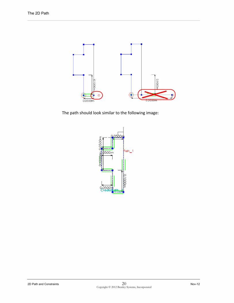
6 For the last (closing point), bring the cursor through the last point, but not too far. If the path stops on the initial point, accept the entry with a left mouse click. If a point and path appear on the other side of the initial point, move the cursor back toward the initial point. If the cursor is within the snap tolerance of the initial point, the shape will close automatically.
Nov-12 19 2D Path and ConstraintsCopyright © 2012 Bentley Systems, Incorporated
The 2D Path
The path should look similar to the following image:
2D Path and Constraints 20 Nov-12Copyright © 2012 Bentley Systems, Incorporated

The 2D Path
7 Left click anywhere in the white space. The path will appear as shown below:
The constraints on the path can now be edited.
8 Left click on the path so that all the dimensions appear. Left click on the left vertical dimension (see the image below).
9 The dimension can be edited by entering the appropriate value and accepting it with either the Enter key or by selecting the green check mark. To cancel the entry, select the red X.
Nov-12 21 2D Path and ConstraintsCopyright © 2012 Bentley Systems, Incorporated

The 2D Path
The image should then look like this:
PC Studio automatically builds constraints based on the order of entry, but this can be easily modified. For instance, in this case, the overall with should drive the size and the stop with should be a resulting dimension. To accomplish this, a constrain may be deleting and then reapplied to another location.
10 Continuing in this file, left click on the path again to edit the constraint system.
2D Path and Constraints 22 Nov-12Copyright © 2012 Bentley Systems, Incorporated

The 2D Path
11 Zoom in to the stop width dimension and right click, then select the Delete option.
This shows two lines as not being fully constrained (since their constraints were based on having the stop dimension present).
Nov-12 23 2D Path and ConstraintsCopyright © 2012 Bentley Systems, Incorporated

The 2D Path
12 The top path segment then needs to be constrained to the bottom. This can be done by right clicking on the portion to be constrained and selecting the constrain type needed, in this case Distance.
13 Next, select the segment indicated in the image below by the red arrow. Subsequently, a new distance constraint will be available and the segments which were formally "blue" are now fully constrained again.
14 Value changes may be made at this level as well. Change the constraint shown below, so that it is different from the other stop depth value. We
2D Path and Constraints 24 Nov-12Copyright © 2012 Bentley Systems, Incorporated

The 2D Path
will later change this so that one is constrained "on" the other, thus eliminating the need for a specific dimension.
Hint: The previous step is not required in a normal workflow, but was done for clarity of this next step. The lower .0500m dimension needed to be eliminated and constrained "on" the line above, as shown in the following image.
Nov-12 25 2D Path and ConstraintsCopyright © 2012 Bentley Systems, Incorporated
The 2D Path
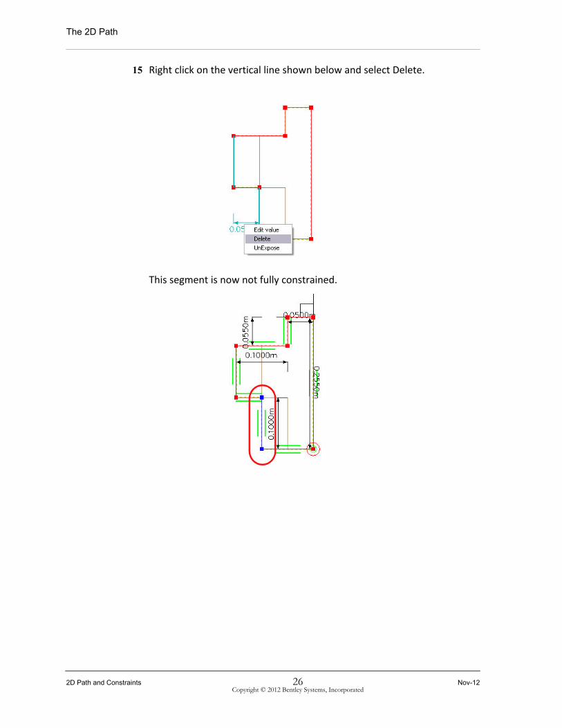
15 Right click on the vertical line shown below and select Delete.
This segment is now not fully constrained.
2D Path and Constraints 26 Nov-12Copyright © 2012 Bentley Systems, Incorporated

The 2D Path
16 Right click on the segment and select On as the constraint type.
17 Select (left click) the segment indicated by the arrow below. Double arrows will appear on the end of this segment indicating that an On constraint has been applied.
Nov-12 27 2D Path and ConstraintsCopyright © 2012 Bentley Systems, Incorporated

The 2D Path
The path should then look something like this:
18 Edit the dimension to match profile specified.
2D Path and Constraints 28 Nov-12Copyright © 2012 Bentley Systems, Incorporated

The 2D Path
19 The final result should look similar to the following image.
Hint: While it is not mandatory, it is strongly recommended that all Path2d elements be created in a counterclockwise direction. The main reason for this is that the Bulge and Radius commands described below will create inward arcs when drawn clockwise.
Nov-12 29 2D Path and ConstraintsCopyright © 2012 Bentley Systems, Incorporated

Path2d Key-in Options
Path2d Key-in Options
The following Shortcut Keys can be used during the creation of a Path2d element to modify how the Path is drawn.
F - Fillet: Creates an arc segment that forms a fillet between the last edge and next edge. This option creates a Fillet with the last edge of the Path2d. It does not (currently) constrain the angle of the next edge, but only creates the proper orientation with the previous edge. It is most useful for arched paths.
B - Bulge: Creates an arc segment by specifying the bulge of the arc. This option creates an arc that is defined by the chord distance and the included angle of the arc from the start point to the end point. You can use the Left and Right arrow keys to adjust the arc's included angle to the desired value. The value of the angle will step up or down by the current Angle Snap value.
R - Radius: Creates an arc segment by specifying the radius of the arc. This option creates an arc that is defined by the direction of the chord between the vertices at its start and end points, and the radius is derived from a combination of the length of the chord and the included angle of the arc. This provides a more convenient dimension inference for editing. During creation, the left/right arrow keys are used to adjust the arc's included angle to the desired value. The value of the angle will step up or down by the current Angle Snap value.
T - Tangent: Creates an arc segment that is tangent to the previous edge. This option creates an arc that is defined by being tangent to the previous edge of the path and the chord length between the vertices at the start point and end point of the arc.
N - Normal: Rotates Drawing plane Normal to Current Plane. This option, when used after the first point of a Path2d, and in combination with a Snap Set element, will rotate the Drawing Plane 90 degrees to be Normal to the plane established when the first point is picked on the Snap Set element.
E - Elevate: Elevates the angle of the Drawing plane from the Current Plane. This option, when used after the first point of a Path2d, and in combination with a Snap Set element, will rotate the Drawing Plane incrementally from the plane established when the first point is picked on the Snap Set element. The incremental angle by which the plane will change is determined by the current Angle Snap value.
<Tab>: Toggles to the next adjacent face of a solid when acquiring the start vertex. This key will toggle between the faces of a solid in the Snap Set when locating the
2D Path and Constraints 30 Nov-12Copyright © 2012 Bentley Systems, Incorporated
Path2d Key-in Options
first vertex of a Path2d on the corner of a solid. This allows you to nominate which face you wish to align your path with. This is shown below and also described in the section on Selecting a Face from and Edge or Vertex in Positioner Basics.
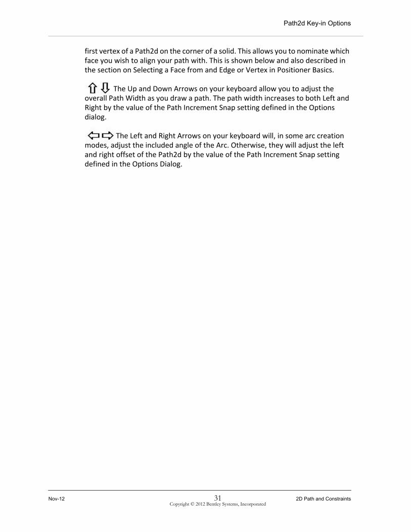
The Up and Down Arrows on your keyboard allow you to adjust the overall Path Width as you draw a path. The path width increases to both Left and Right by the value of the Path Increment Snap setting defined in the Options dialog.
The Left and Right Arrows on your keyboard will, in some arc creation modes, adjust the included angle of the Arc. Otherwise, they will adjust the left and right offset of the Path2d by the value of the Path Increment Snap setting defined in the Options Dialog.
Nov-12 31 2D Path and ConstraintsCopyright © 2012 Bentley Systems, Incorporated

Path2d Key-in Options
2D Path and Constraints 32 Nov-12Copyright © 2012 Bentley Systems, Incorporated

Variables and Named Dimensions
Module Overview
The objective of this lesson is to convey the concept of Named Dimensions and Variables in PC Studio. Parametric Cells may contain Named Dimensions and Variables, which provide user-named values that can be accessed across an assembly. Named Dimensions can only be added to one dimension object in a model. Variables are more flexible and can be used to control any number of Dimensions and in Expressions or other parameters on Actions. Changes to Variables are automatically propagated to other objects within their Parametric Assembly.
Module Prerequisites• Using the PC Studio User Interface.
• Opening and creating PC Studio files.
• Creating and modifying a 2D Path element.
Module Objectives
After completing this module, you will be able to:
• Create and use Variables.
• Create and use Named Dimensions.
Nov-12 33 Variables and Named Dimensions
Copyright © 2012 Bentley Systems, Incorporated

Adding Variables
Adding Variables
Variables in PC Studio provide a flexible way of defining and calculating values that can be applied in expressions or dimensions any number of times. Unlike Named Dimensions, they are not linked to an individual dimension or component. The variables in a PC Studio model are listed in the Variables folder in the Component Catalog as shown below. In the Container view, a variable is shown with the Variable Icon.
Exercise: Adding Variables
In this exercise, you will control the dimensions of the frame profile (Path2d drawn in previous exercise) by assigning pre-defined variables to the dimension.
1 Click the Open File Icon and choose the file 02_FrameProfile.pac.
2 Select the path (once) and click on the dimension (0.200m).
3 In the Dimension Edit window, type in =\, and then choose the named object browser.
4 From the Variables list, choose FrameDepth, and then click OK. (Or you can double-click the variable name).
Variables and Named Dimensions 34 Nov-12Copyright © 2012 Bentley Systems, Incorporated

Adding Variables
5 The expression, when completed, should appear as follows:
6 Add the Variable for the FrameThickness.
7 Modify the Value of the assigned Variables in the variables folder in the Component Catalog.
Note: The '=' sign isn't necessary, but it is a good habit to use it to start an expression. This is also a good visual differentiation from the definition of Named Dimensions.
Note: The backslash '\' tells PC Studio to always look at the top or Root level of a model to find the value of the variable. The backslash enables a global approach to the use of variables and helps avoid having multiple variables with the same name appear in both PC Studio and in AECOsim Building Designer Architecture with different values. If the backslash is not used, the variable will remain the value defined in the Component.
Nov-12 35 Variables and Named DimensionsCopyright © 2012 Bentley Systems, Incorporated

Creating Variables
Creating Variables
Exercise: Creating Variables
In the previous exercise, we used pre-defined variables to define the values of two dimensions. You will now create one more variable and apply this to the Path.
1 In the Component Catalog window, open the Variable panel.
2 In an open space, right-click, and from the pop-up menu, choose New. This will open the New Variable dialog.
3 Create a new variable called DoorStopThickness, with type set to Length and a typical Door-stop Thickness value.
4 Assign the new Variable to the Door-stop dimension.
5 Save your file.
Note: Variable Names must be spelled correctly and are case sensitive. Using the Named Object Browser provides a way of reducing errors due to typographical mistakes.
Note: The "Visible" toggle on the New or Edit Variable dialog tells AECOsim Building Designer Architecture whether to show this variable in its placement dialogs and thereby make it editable or non-editable.
Variables and Named Dimensions 36 Nov-12Copyright © 2012 Bentley Systems, Incorporated

Named Dimensions
Named DimensionsNamed Dimensions are similar to Variables, except that they are defined on a dimension. They can be referenced from other dimensions, but they are contained within the component in which they exist and cannot, therefore, change their value in a global sense to match a variable or named dimension higher up in the hierarchy of a model. For this reason, Named Dimensions are best utilized in a final model, or where you want to have specific dimensions applied to a particular component.
A Named Dimension, when contained within a component, is accessed by a concatenation of the component named with the dimension name and separated by a period. For example, a dimension named DoorWidth in a component called Door1 would be accessed as Door1.DoorWidth.
Named Dimensions are assigned to a dimension constraint using the format Name = Expression. For example: Width = 900mm or Height = Width * 1.6
Exercise: Naming Dimensions
1 Click the Open File Icon and choose the file 03_ReferencePath.pac
2 Click on the Red path. Its name, ReferencePath, should appear as your pointer hovers over it. Once selected, a vertical and horizontal dimension should appear.
Nov-12 37 Variables and Named DimensionsCopyright © 2012 Bentley Systems, Incorporated

Named Dimensions
3 Left-click on the horizontal (1.0000 m) dimension, and enter Width = 1.0000 m in the Edit window.
4 Click the green tick symbol to complete the definition.
5 Similarly, click on the vertical (1.8000 m) dimension and enter Height = 2.1000 m.
6 Click the green tick symbol to complete the definition. This will not only assign the Named Dimension, but also define a new value for the dimension and change the height of the Assembly.
Note: Note that Named Dimensions can only be changed by selecting the dimension to edit the value. Named dimensions do not appear in the Variables panel.
Variables and Named Dimensions 38 Nov-12Copyright © 2012 Bentley Systems, Incorporated

Door Components
Module Overview
Bentley PC Studio is based on the concept of nested, hierarchical assemblies. Components are the building blocks of these assemblies. This is one of the most powerful concepts within Bentley PC Studio and provides the ability to create an unlimited number of re-usable parametric parts to compose new models.
Module Prerequisites• Using the PC Studio User Interface.
• Opening and creating PC Studio Files.
• Creating and modifying a 2D Path element.
• Creating and using variables and named dimensions.
Module Objectives
After completing this module, you will be able to:
• Create components.
• Assemble components.
Nov-12 39 Door Components
Copyright © 2012 Bentley Systems, Incorporated

Creating Components
Creating Components
A Sweep Component is a specialized type of Component used to create a Solid by using a Sweep Along Path operation. Creating a Sweep Component is the first step in creating a Sweep Solid. The Sweep Component forms the dimension-driven profile (or cross section) of your Sweep Solid, so it must be created from a single closed Path2d object which you have done in a previous exercise. This Component is selected and located on another Path in your Snap Set and extruded to create a Solid.
Exercise: Creating A Sweep Component
1 Click the Open File Icon and choose the file 04_FrameProfile.pac.
2 Choose the Sweep Component Tool from the Component Toolbar or choose Define Sweep from the Component menu.
3 Select the frame profile (form must be an enclosed area and does not intersect itself) and press <Enter>.
4 The new Component Definition will be displayed in the Position the Positioner dialog. You will be asked to Position (or locate) the Sweep component positioner, which also appears in the dialog view window temporarily located at the origin of the path.
Door Components 40 Nov-12Copyright © 2012 Bentley Systems, Incorporated

Creating Components
5 Move your cursor into the Position the Positioner view window, and the Positioner will jump to the cursor ready for final placement.
6 Select the location of the Sweep Positioner by the axis along an edge or vertex of the Path2d.(i.e. as indicated below). Press <Enter> or click OK to complete this step.
7 You will be presented with the Component Name dialog, with a default name as shown below left. You can modify this name to something more meaningful, as shown below right.
8 Once you provide a name, press <Enter> or click OK, and a new icon (highlighted below) representing the new Component will appear in the Local Components palette.
Nov-12 41 Door ComponentsCopyright © 2012 Bentley Systems, Incorporated

Placing a Component
Placing a Component
Placing components in your model is an important part of creating Parametric Cells. PC Studio allows you to select a Component from either the Local Component palette or any number of Component Libraries that you import into your model. Local Components and loaded Component Libraries are usually located on the left side of the application window. Selecting a component from these palettes will create an instance of that Component in your active file. This can be placed at a specific location, which will include associative dimensional relationships with other objects in the model.
Exercise: Placing a Sweep Component
In this exercise, you will use the previously-created Sweep Component and create a Door Frame.
1 Click the Open File Icon, and choose the file 05_FrameSweep.pac.
2 Using the Snap Set tool, select the red Path (ReferencePath). It will highlight as red dotted lines as shown below. Press <Esc> to Exit the Snap Set tool.
3 From the Local Component panel, choose the FrameSweep component. This will place the component in the center of your page, as shown below
Door Components 42 Nov-12Copyright © 2012 Bentley Systems, Incorporated

Placing a Component
left. The Simple Extrusion positioner you located when you created the component appears in blue.
4 Select the component in the middle of the Blue positioner line, and drag it to the right bottom edge of the Path. Check the orientation of the Profile. If necessary, press the <R> key to rotate the ProfilePath to the correct orientation, as seen below left, and then Left-click.
Nov-12 43 Door ComponentsCopyright © 2012 Bentley Systems, Incorporated

Creating an Auto Component
5 Select the remaining blue positioner and drag it to the lower left corner, as indicated below. Left-click to confirm the point.
6 Press the <Enter> key to complete the placement of the Component.
7 Save the File.
Creating an Auto Component
An Auto component is the most common Component in PC Studio. Most Assemblies will be saved as an Auto Component. The Define Auto option is used to create components that contain any number of parts ready to be placed in a larger assembly. These types of components are created with a Profile Positioner created from an initial Path2d, which allows them to be stretched to fit other geometry when being placed.
Exercise: Auto Component
In this exercise, you will create a door leaf and save it as an Auto Component.
1 Click the Open File Icon and choose the file 06_DoorLeaf.pac.
2 Choose the Extrude By Axis Tool from the Create Toolbar or from the Tools > Extrude by Axis menu.
3 Select the rectangle Path2d element (DoorLeafPath).
Door Components 44 Nov-12Copyright © 2012 Bentley Systems, Incorporated

Creating an Auto Component
4 A solid with a default extrusion thickness will be created, and a Positioner will display along the edge of the selected Path2d.
5 Manipulate the Positioner's Vertices until the desired extrusion is achieved. Press <Enter> to complete the extrusion and terminate the tool.
6 Left-click on the extruded Solid, then on the Dimension, and enter =\DoorThickness*-1 in the Dimension Edit window. Press Enter or click green Check to accept.
7 Select the Define Auto Component tool.
8 You can now select all the components using a selection box. They will be highlighted with yellow dotted lines.
Nov-12 45 Door ComponentsCopyright © 2012 Bentley Systems, Incorporated

Creating an Auto Component
9 Press the <Enter> key when all required elements are selected. This will open the Edit Component dialog. The Profile Positioner Path is highlighted. Click OK.
10 The Component Name dialog appears with a default name. Change this to DoorLeaf_01, and then click OK or Press <Enter>.
11 The new component is added to the Local Component panel.
12 To save the component to an external component file, choose the component you want to save in the Local Component panel.
Door Components 46 Nov-12Copyright © 2012 Bentley Systems, Incorporated

Creating an Auto Component
13 Right-click on it, and select the Save As command from the popup menu.
14 Navigate to the C:\PCS_Training\Library_Files directory and keep the name DoorLeaf_01 for the component.
15 Press the Save button to complete the operation. The local component of the door leaf will be saved to an external file that can be placed into other models from a Component Library command in the popup menu.
16 Continuing in 06_DoorLeaf, put a door leaf extrusion in the snap set.
Nov-12 47 Door ComponentsCopyright © 2012 Bentley Systems, Incorporated

Creating an Auto Component
17 Move your cursor over the door and begin drawing a path similar to the image below:
18 Using the selection tool, click on the path just created twice to edit the constraints and delete the red circle.
Door Components 48 Nov-12Copyright © 2012 Bentley Systems, Incorporated

Creating an Auto Component
Hint: If you are have trouble seeing the new path, the path color may be changed prior to placing the path or afterward using the path properties. The paths may also be renamed for clarity.
The paths should now display all blue (indicating that they are not fully constrained).
This is because the red circle indicated the original placement point and thus constrained the origin of the path. By deleting this constraint all the other constraints lost the dependency and thus need additional constraints applied.
Nov-12 49 Door ComponentsCopyright © 2012 Bentley Systems, Incorporated

Creating an Auto Component
19 Right click on the path and add Distance constraints to the edges of the door leaf.
20 Continue until desired constraints are achieved.
Optionally, the center constraints may be deleted as well and the other edges constrained outside of the left.
Door Components 50 Nov-12Copyright © 2012 Bentley Systems, Incorporated

Creating an Auto Component
21 Once this is done, use the Cut Through tool and select the path and create a cut.
22 Create an additional component for this and Save as similar to the flush door leaf.
Nov-12 51 Door ComponentsCopyright © 2012 Bentley Systems, Incorporated
Loading a Component Library
Loading a Component LibraryA Component Library is a directory that contains a set of Components saved to separate files. This way, Components can be organized into sub-directories of related parts and sub-assemblies.
Exercise: Loading a Component Library
In this exercise, you will load a Component Library with the door leaf saved from the previous exercise.
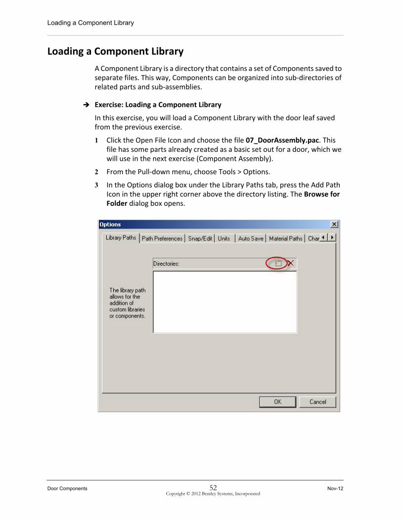
1 Click the Open File Icon and choose the file 07_DoorAssembly.pac. This file has some parts already created as a basic set out for a door, which we will use in the next exercise (Component Assembly).
2 From the Pull-down menu, choose Tools > Options.
3 In the Options dialog box under the Library Paths tab, press the Add Path Icon in the upper right corner above the directory listing. The Browse for Folder dialog box opens.
Door Components 52 Nov-12Copyright © 2012 Bentley Systems, Incorporated

Loading a Component Library
4 Select the PCS_Training folder, and press <Enter>.
5 The Component Library Path appears in the directory listing. Exit the Options dialog by clicking OK.
6 From the file menu, select Load Component Library. This command will display all of the Libraries (Directories) in your current Component Library Paths that contain PC Studio files. Multiple directories can be selected.
Nov-12 53 Door ComponentsCopyright © 2012 Bentley Systems, Incorporated

Assembling Components
7 Select the Library Directory that you want to load. In the following example, the Component library for our Library Files is selected.
8 Press Load to complete the operation.
9 The content of the Library Files folder is available on the left-hand side under Local Components.
Assembling Components
A Component Library is a directory that contains a set of Components saved to separate files. This way, Components can be organized into sub-directories of related parts and sub-assemblies.
Exercise: Door Component Assembly
Door Components 54 Nov-12Copyright © 2012 Bentley Systems, Incorporated
Assembling Components
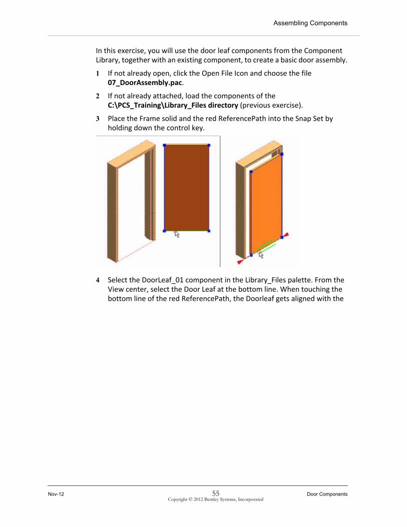
In this exercise, you will use the door leaf components from the Component Library, together with an existing component, to create a basic door assembly.
1 If not already open, click the Open File Icon and choose the file 07_DoorAssembly.pac.
2 If not already attached, load the components of the C:\PCS_Training\Library_Files directory (previous exercise).
3 Place the Frame solid and the red ReferencePath into the Snap Set by holding down the control key.
4 Select the DoorLeaf_01 component in the Library_Files palette. From the View center, select the Door Leaf at the bottom line. When touching the bottom line of the red ReferencePath, the Doorleaf gets aligned with the
Nov-12 55 Door ComponentsCopyright © 2012 Bentley Systems, Incorporated

Assembling Components
door frame. Left-click to constrain the bottom of the door leaf to the bottom of the ReferencePath.
5 Select the left blue line to constrain the door leaf to the left side of the frame. Use the D Key before you left-click, to allow for a distance of 5mm. It is easier to enter the value when selecting the dimension after the rough placement of the door leaf.
Repeat this step to constrain the right and top of the door leaf.
6 Press <Enter> to complete the operation.
7 Create a new Auto Component of the door following steps 7 to 11 of the Auto Component Exercise.
Door Components 56 Nov-12Copyright © 2012 Bentley Systems, Incorporated

Substituting Components
8 Save the Component into your Library_Files folder by following steps 12 to 15 of the Auto Component Exercise.
Substituting Components
With the Substitute command, you can quickly exchange one component with another, thus being able to rapidly create different versions of architectural objects.
Exercise: Substitute Component
In this exercise, you will exchange the door leaf with one you created in the previous exercise, available in the Component Library.
1 If not already open, click the Open File Icon and choose the file 07_DoorAssembly.pac.
2 If not already attached, load the components of the C:\PCS_Training\library_Files directory.
3 Choose the component DoorLeaf_02 and right-click on it.
4 Select the Substitute … command from the popup menu.
Nov-12 57 Door ComponentsCopyright © 2012 Bentley Systems, Incorporated

Positioning Key-in Options
5 In the Choose component definition to replace dialog box, choose the component that you would like to substitute.
6 Click OK. A dialog will appear telling you how many instances have been substituted.
7 Click OK to complete the operation.
8 Create a new Auto Component of the door following steps 7 to 11 of the Auto Component Exercise.
9 Repeat steps 3 to 8 of this exercise for the component DoorLeaf_03.
10 Save the new Components into your Library_Files folder by following steps 12 to 15 of the Auto Component Exercise.
Positioning Key-in Options
Most Positioning operations will respond to the following key-in options, but there are some exceptions for specific tools.
D: Toggles the Distance Dimension mode from the currently highlighted geometry. Use the D Key-in shortcut to toggle Distance dimension mode. When the selected PosGeom is coincident with some geometry that enables PC Studio to create a valid Distance dimension, it will turn on Distance dimension mode. Subsequent dimension samples will contain a non-zero distance dimension with that geometry - usually an edge or point on an element contained in the Snap Set.
F: Inverts the Positioner by Flipping the primary axis and reversing its direction. Using the F shortcut key-in will Flip the Positioner by inverting its primary axis. If the Positioner cannot be flipped because it would violate existing dimensions, an error message will be displayed.
Door Components 58 Nov-12Copyright © 2012 Bentley Systems, Incorporated

Positioning Key-in Options
R: Rotates the Positioner around its primary axis. Using the R Shortcut key-in will rotate the Positioner about its primary axis for a Simple Extrusion or Rigid Body Positioner, or the normal of a Profile Positioner.
Nov-12 59 Door ComponentsCopyright © 2012 Bentley Systems, Incorporated

Positioning Key-in Options
Door Components 60 Nov-12Copyright © 2012 Bentley Systems, Incorporated

Publishing to AECOsim Building Designer Architecture
Module Overview
In this lesson, you will learn how to publish your PC Studio object to AECOsim Building Designer Architecture.
In order for AECOsim Building Designer Architecture to interpret your window and door cells correctly, some prerequisites are necessary. These prerequisites are discussed in earlier modules of this course and are not covered in the following exercise.
Module Prerequisites• Using the PC Studio user interface, tool basics and shortcut key-ins.
• Opening and creating PC Studio files.
• Creating and modifying a 2D Path element.
• Creating and using variables and named dimensions.
• Creating and assembling components.
Module Objectives
After completing this module, you will be able to:
• Publish components to AECOsim Building Designer Architecture.
Nov-12 61 Publishing to AECOsim Building Designer Architecture
Copyright © 2012 Bentley Systems, Incorporated

Publishing Components
Publishing Components
Exercise: Publishing to AECOsim Building Designer Architecture
In this exercise, the previously assembled Door will be published to AECOsim Building Designer Architecture.
1 Click the Open File Icon, and choose the file 08_Publishing.pac.
2 From the File menu, select Publish…
3 The Publish Options dialog appears. Click OK to accept the default Options. The cell is published, with the extension .paz, to the specified directory.
4 In the Publish dialog, browse to the doors directory of your dataset. …\Bentley\AECOsimBuildingDesigner
Publishing to AECOsim Building Designer Architecture 62 Nov-12Copyright © 2012 Bentley Systems, Incorporated

Publishing Components
V8i\WorkSpace\BuildingDatasets\Dataset_US\frame\doors\ in a standard installation.
5 In the File Name, notice the default name for the *.paz cell. Press Publish to accept.
6 Start AECOsim Building Designer Architecture. Choose your current User and Project. Select Empty.dgn in the Files listing, and click OK.
7 From the Utilities menu, choose Key-in.
8 In the Key-in dialog, type mdl load catalogutil and run Key-in. Loading the catalogutil is only necessary once - before you run the first update during a AECOsim Building Designer Architecture session.
Nov-12 63 Publishing to AECOsim Building Designer ArchitectureCopyright © 2012 Bentley Systems, Incorporated

Publishing Components
9 In the Key-in dialog, type atfcatalogutil update all and run Key-in. The Update Catalog Files dialog opens. Activate the Door entry and click OK to complete the operation.
10 From the Architectural Modeling palette, choose the Place Door command. Refresh the Library.
The new Parametric Door will be part of the display list in the Place Door dialog.
11 Proceed by placing the door as usual.
Note: The same procedure is applicable for windows. Instead of publishing to the Doors directory, choose the Windows directory. In the Update Catalogue Files dialog, activate Window instead of Door.
Publishing to AECOsim Building Designer Architecture 64 Nov-12Copyright © 2012 Bentley Systems, Incorporated

Path Offest
Module Overview
PC Studio provides tools to create and place paths and components with associative or dimensionally constrained relationships. These hierarchical relationships are the backbone of creating component assemblies. In this lesson, we will look at how these tools work with Path2d elements. You will create offset paths and place a path component. These actions form the basis of more complex tasks. Copying Path2d elements with an offset is a powerful feature of PC Studio's Dimension Driven associability.
Copying a Path2d allows you to make hierarchical structures, all linked associatively with the original path. You can copy paths as parallel (in the same plane), perpendicular, or with an Angle of Incline to the original path.
Module Prerequisites• Using the PC Studio User Interface.
• Opening and creating PC Studio files.
• Creating a 2D Path, creating and using variables and named dimensions, and creating and assembling components.
• Publishing components to AECOsim Building Designer Architecture.
Module Objectives
After completing this module, you will be able to:
• Create and place offset paths.
• Assign properties on offset paths.
Nov-12 65 Path Offest
Copyright © 2012 Bentley Systems, Incorporated

Create an Offset Path
Create an Offset Path
Exercise: Creating a Parallel Offset Copy of a Path
In this exercise, you will create an offset copy of the ReferencePath element to demonstrate how you can easily create paths which are linked together associatively.
1 Click the Open File Icon and choose the file 09_RoughOpeningPath.pac.
2 Choose the Copy Path2d Parallel tool from the Create Toolbar.
3 Select the red Path2d element (ReferencePath). A second Path2d object will appear offset 50mm in the same plane as the first path. At this point, the path is a temporary object.
4 Press the <Enter> key to complete the creation of the new Path. The distance between the original path and the copy is determined by the Distance Snap setting. In this case, it is 50mm and is indicated in the status bar at the bottom right of the screen.
Let's assume that the new Path is the indicator for the Rough Opening of a Window. For AECOsim Building Designer Architecture to interpret this correctly as the Perforator, the following steps are necessary.
Path Offest 66 Nov-12Copyright © 2012 Bentley Systems, Incorporated

Create an Offset Path
5 Right-click to open the Path Properties dialog for the newly created path. Under the General Tab, change the Name of the offset path to RoughOpening (case sensitive). If desired, change the color to black.
6 Switch to the Attributes Tab in the Path Properties dialog. Right-click and choose New. The New Attribute dialog opens.
Nov-12 67 Path OffestCopyright © 2012 Bentley Systems, Incorporated

Create an Offset Path
7 The RoughOpening path is used as the perforator in AECOsim Building Designer Architecture. For it to work correctly, it must contain three special attributes. Add the attributes as shown in the figure below.
RoughOpening Attribute Options:
Blind
• Type: Boolean.
• Possible Values: True or False (selected from the drop-down list box when Boolean is selected for Type)
The Blind attribute controls the depth of the cut with respect to the Sense Distance. If the Value assigned to Blind is False, the RoughOpening Perforator will cut all the way through any forms found within the Sense Distance. If the Value assigned to Blind is True, the RoughOpening Perforator will only cut to the depth of the Sense Distance. This option can be used to cut pockets into forms for recessed cabinets, sliding doors etc.
Directional
• Type: Integer
• Possible Values: 2, 1, or -1
The Directional attribute controls the direction of the cut from the RoughOpening path when the cell is placed in AECOsim Building Designer Architecture. If the Value of Directional is 2, then the cut will be 2 way; that is, it will cut in both directions perpedicular to the plane of the path. If
Path Offest 68 Nov-12Copyright © 2012 Bentley Systems, Incorporated

Placing a Path Component
the Value of Directional is 1, then the direction of the cut will be outward from the path. If the Value of Directional is -1, then the direction of the cut will be inwards from the path. For use in doors and windows, the logical value of Directional will be either 2 or -1.
SenseDistance
• Type: Length
• Possible Values: any length value.
SenseDistance is the distance TriForma will search from a perforator for elements to cut. The SenseDistance attribute contains the default value you wish to apply to the Triforma Sense Distance search. This value can be modified in the tool dialog at placement time or in the Perforators tab of the TriForma Element Info dialog when a Parametric Cell is selected.
8 Click OK to complete the operation.
9 Save your file.
Placing a Path Component
Exercise: Adding the RoughOpening Path as a Component
In this exercise, you will place the RoughOpening Path as a component.
1 Click the Open File Icon and choose the file 10_RoughOpeningPath.pac.
2 Add the red Path2d element (ReferencePath) to the snap set. From the Local Components Panel select the RoughOpeningComp.
Nov-12 69 Path OffestCopyright © 2012 Bentley Systems, Incorporated

Placing a Path Component
The component will appear in the current view. It appears blue to indicate that it is not constrained.
3 Select the Bottom edge of the RoughOpening path component, and move it to the bottom edge of the Reference path selected in the Snap Set. Note that the new path component realigns itself with the plane of the existing path.
4 Left-click to accept this association. The Bottom edge of the element in the snap set is highlighted with a heavy red dashed line and arrowhead markers at either end. This will indicate an alignment constraint on the element. This time we will add a constraint with dimensional offset, similar to that in the copy tools used earlier.
5 Select the Top edge of the RoughOpeningComp path component, and move it until it aligns with the top edge of the existing path. It will highlighted in red with arrow pointers when it aligns. (Do not click yet).
6 When it aligns, type the letter D, for Distance, to create a distance constraint, and then move your pointer downward. A dimension will appear between the two objects as seen below left.
7 Left-click to accept.
8 Repeat this action with the respective sides of the RoughOpening path and with the ReferencePath path.
9 When you have constrained all edges of the path component, press the <Enter> key to accept the final placement of the new path component.
10 Left-click in the view window to complete the operation.
11 Save your File.
Path Offest 70 Nov-12Copyright © 2012 Bentley Systems, Incorporated

Creating a Perpendicular Offset Copy of a Path
Creating a Perpendicular Offset Copy of a Path
Exercise: Creating a Perpendicular Offset Copy of a Path
In this exercise, you will create the elements for a GlassPanel component by offsetting a Path perpendicular and Extruding the offset path to a solid.
1 Click the Open File Icon and choose the file 11_GlassPanel.pac.
2 Select the Copy Path2d Perpendicular tool from the Create Toolbar.
3 Select the Green Path2d element (GlassPanel_RefPath). A new path is created 50mm away from the previous path, but perpendicular to the plane of the green path.
4 Select the Blue Constraint point on the new copy of the path (the front path shown above) and move your cursor to define the offset distance. You can move it forward or backward. Move it to a distance of approximately 300-400mm behind the green paths.
5 Left-click to accept the distance and direction.
6 Press the <Enter> key to complete the creation of the new Path.
Note: In either Parallel or Perpendicular mode, you can press the A key to start Angle mode. You can then offset the new copy at an inclined angle from the original path. If you select Parallel Mode and move your angle through to 90 degrees, you are effectively creating the same as a perpendicular copy.
7 Open the Path Properties dialog for the newly created path. Under the General Tab, change the Name of the offset path to GlassPanel_InsetPath. If desired, change the color.
Nov-12 71 Path OffestCopyright © 2012 Bentley Systems, Incorporated

Creating a Perpendicular Offset Copy of a Path
8 Left-click on GlassPanel_InsetPath, then on the Dimension, and assign the GlassInset variable =\GlassInset in the Dimension Edit window. Press Enter or click the green Check to accept.
9 Choose the Extrude By Axis Tool from the Create Toolbar or from the Tools > Extrude by Axis menu.
10 Change the Segment in the Current Properties Toolbar to Model3d and the color to GlassGray.
11 Select offset Path2d element (GlassPanel_InsetPath).
12 A solid with a default extrusion thickness will be created, and a Positioner will display along the edge of the Path2d that was selected.
13 Move the Positioner's Vertices approximately 10-15 cm to the back. Press <Enter> to complete the extrusion and terminate the tool.
14 Left-click on the extruded Solid and then on the Dimension. Assign the GlassThickness variable =\GlassThickness*-1 In the Dimension Edit window. Press Enter or click the green Check to accept.
15 Left-click into the view window or click ESC to complete the operation.
16 Save your File.
Path Offest 72 Nov-12Copyright © 2012 Bentley Systems, Incorporated
Window Components
Module Overview
As seen in a previous lesson, PC Studio is based on the concept of nested, hierarchical assemblies. Components are the building blocks of these assemblies. This is one of the most powerful concepts within PC Studio and provides the ability to create an unlimited number of re-usable parametric parts to compose new models. In this lesson, we will create components that belong to a Window.
Module Prerequisites• Using the PC Studio User Interface.
• Opening and creating PC Studio files.
• Creating a2D Path, creating and using variables and named dimensions, and creating and assembling components.
• Publishing components to AECOsim Building Designer Architecture.
• Creating offset paths.
Module Objectives
After completing this module, you will be able to:
• Create components that contain any number of Parts.
• Create simple extrusion components using the Define Simple Extrusion tool.
Nov-12 73 Window Components
Copyright © 2012 Bentley Systems, Incorporated
Creating an Auto Component
Creating an Auto Component
The Define Auto option is used to create components that contain any number of parts ready to place in a larger assembly. These types of components are created with a Profile Positioner created from an initial Path2d which allows them to be stretched to fit other geometry when being placed.
Exercise: Creating an Auto Component
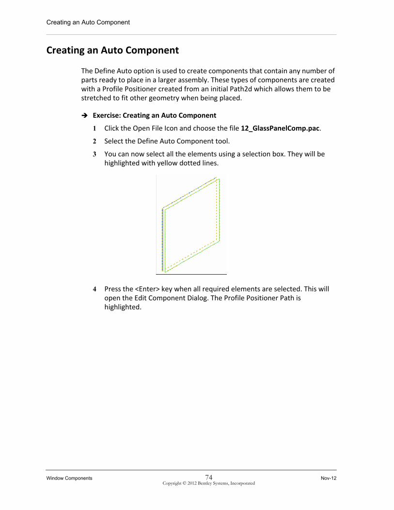
1 Click the Open File Icon and choose the file 12_GlassPanelComp.pac.
2 Select the Define Auto Component tool.
3 You can now select all the elements using a selection box. They will be highlighted with yellow dotted lines.
4 Press the <Enter> key when all required elements are selected. This will open the Edit Component Dialog. The Profile Positioner Path is highlighted.
Window Components 74 Nov-12Copyright © 2012 Bentley Systems, Incorporated

Simple Extrusion
5 Right-click on the left vertical line, and choose Set as Primary. This will turn the vertical line as the Primary placement line and is indicated by the blue color.
6 Click OK. The Component Name dialog appears with a default name. Change this to GlassPanelComp, and then click OK or Press <Enter>.
7 The new component is added to the Local Component panel.
Simple Extrusion
Simple Extrusions can form the basis of many assemblies. They can be used to create frames with varying sections, arrays of elements such as Mullions, and many other elements. The general procedure to create an Extrusion component is to define a path, extrude it to a solid, and then create the component using the Define Simple Extrusion tool.
Nov-12 75 Window ComponentsCopyright © 2012 Bentley Systems, Incorporated

Simple Extrusion
Exercise: Simple Extrusion
In this exercise, you will create a simple extrusion component.
1 If not already open, click the Open File Icon and choose the file 12_GlassPanelComp.pac.
2 Change to a Top View.
3 With the Path2d tool, draw a Profile. Linethickness = 0.
4 Assign the variables FrameThickness and FrameDepth to the Profile.
5 Change to a Left Isometric View.
6 In the Segment pull-down of the Current Properties Tool bar, choose the Segment Model3d. When we are creating elements that will form a solid part of our model in the Microstation application, we must place those objects on the Model3d Segment.
Window Components 76 Nov-12Copyright © 2012 Bentley Systems, Incorporated

Simple Extrusion
7 Extrude Profile with the Extrude by Axis Tool from the Create Toolbar to a height of at least 200mm.
8 Choose the Define Simple Extrusion Tool, and then select just the solid element with a mouse click. Press the <Enter> key.
9 The Position the Positioner dialog appears. This lets you select the desired location on the solid that you want to use to connect this component to other elements - a kind of Origin. This is seen in the following image.
10 Move the positioner to the location shown and click to accept.
11 Click OK (or press <Enter>) to complete this step.
Nov-12 77 Window ComponentsCopyright © 2012 Bentley Systems, Incorporated

Simple Extrusion
12 In the Component Name Dialog, enter the name MullionSimpExtrusion, and then click OK.
13 The component will appear in the Local Component panel of the Component Catalog.
14 Save all local components to the C:\PCS_Training\Library_Files directory and keep the default name for the component.
Exercise: Window Component Assembly - Fixed Mullion
In this exercise, you will create a window using the previously created window components and a template file. The Template file for this exercise contains several related Path2d Elements along with some predefined Variables. Some of these variables are used in the components you will use.
Note: The following three paths are hidden but are essential when publishing Windows to AECOsim Building Designer Architecture. The Red Path is named ReferencePath. This is the Element which, when placed in a Building product, will align with the face of a wall. The Black Path is the cutting element (perforator) which will make the opening for the window. You can have more than one cutting element, but the name must begin with RoughOpening. In this model, the Path is called RoughOpening_1 and is offset parallel to the ReferencePath. The Green Path is named FrontOffsetPath. This is where the face of the window will be attached. This path is offset perpendicular to the ReferencePath, and the distance between these determines the front offset depth of the frame into (or out of) the wall. The offset Dimension is assigned a variable called FrontOffset.
To complete the exercise, make sure the C:\PCS_Training folder is covered in your Library Path list in the Options dialog.
Window Components 78 Nov-12Copyright © 2012 Bentley Systems, Incorporated
Simple Extrusion
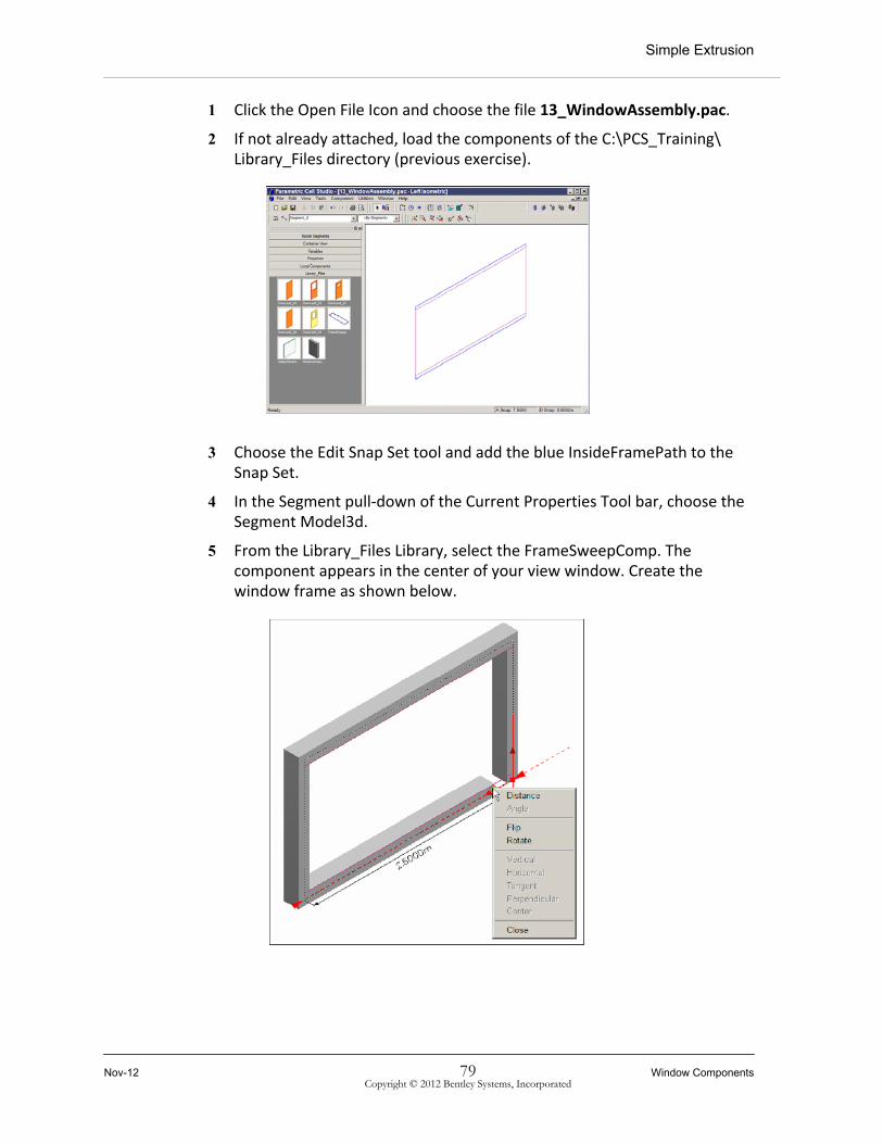
1 Click the Open File Icon and choose the file 13_WindowAssembly.pac.
2 If not already attached, load the components of the C:\PCS_Training\ Library_Files directory (previous exercise).
3 Choose the Edit Snap Set tool and add the blue InsideFramePath to the Snap Set.
4 In the Segment pull-down of the Current Properties Tool bar, choose the Segment Model3d.
5 From the Library_Files Library, select the FrameSweepComp. The component appears in the center of your view window. Create the window frame as shown below.
Nov-12 79 Window ComponentsCopyright © 2012 Bentley Systems, Incorporated

Simple Extrusion
Note: To close the Frame, right-click in the view Window and choose Close.
6 Hide the newly created frame solid.
7 Choose the Edit Snap Set tool and add the blue ArrayPath to the Snap Set.
8 From the Library_Files Library, select the MullionComp. The component appears in the center of your view window.
9 Select the bottom blue positioner point and move it to the bottom-center of the snap set path. When you see the green circle highlight the middle snap point, click to accept the location.
Window Components 80 Nov-12Copyright © 2012 Bentley Systems, Incorporated

Simple Extrusion
10 Select the top blue positioner point, move your cursor, and click on the top-centre of the snap set path. Don't worry if the mullion doesn't stretch or rotates to an odd angle.
11 Select the blue dotted arrow at the bottom of the Mullion (zoom in if necessary) and align it with the snap set path. This is the rotation positioner, which must be constrained (appear red) to make sure that the rotation of the Mullion is fixed within the window assembly.
12 Press <Enter>to complete the command.
Nov-12 81 Window ComponentsCopyright © 2012 Bentley Systems, Incorporated

Simple Extrusion
13 In the Container View, change the FrameSolid properties to Show.
14 The window should look like this so far.
15 Add the GlassPanelComp Component by placing the frame solid and the mullion into the SnapSet. Proceed to finish the window, as in the previous exercise Door Component Assembly. Check your Assembly by modifying variables and size.
Window Components 82 Nov-12Copyright © 2012 Bentley Systems, Incorporated

Component Array
Module Overview
PC Studio allows you to create Arrays of Components along a Path2d, or even a path belonging to the face of a Solid. Array Along Path does what the name implies; it creates an Array of the selected Component along a Path2d at a user-specified spacing and orientation. This is one of the most powerful Actions in Parametric Cells. It has many options to help space the Array along the path, and it can be used to create railings, stairs, Curtain walls, framing elements, and a host of other objects.
Module Prerequisites• Using the PC Studio User Interface.
• Opening and creating PC Studio files.
• Creating a2D Path, creating and using variables and named dimensions, and creating and assembling components.
• Publishing components to AECOsim Building Designer Architecture.
• Creating offset paths.
• Creating components that contain any number of Parts.
• Creating simple extrusion components using the Define Simple Extrusion tool.
Module Objectives
After completing this module, you will be able to:
• Create a window using an Array.
Nov-12 83 Component Array
Copyright © 2012 Bentley Systems, Incorporated

Create an Array Along a Path
Create an Array Along a Path
The Array Along Path command is not like other tools that are selected from the menu or tool bar. It is initiated by using the Local or Library Component Folder and using the right-click pop-up menu (while the mouse is over the desired array component), and selecting the Array Along Path command. This method allows the quick selection of the both the component and the command in one action.
Exercise: Creating an Array Along a Path
In this exercise, you will create a window using the previously created MullionSimpExtrusion components in a template file. The Template file for this exercise contains several related Path2d Elements along with some predefined Variables. Some of these variables are used in the components you will use.
To complete the exercise, make sure the C:\PCS_Training folder is covered in your Library Path list in the Options dialog.
1 Click the Open File Icon, and choose the file 14_MullionArray.pac.
2 If not already attached, load the components of the C:\PCS_Training\ Library_Files directory (previous exercise).
3 Choose the Edit Snap Set tool, and add the purple ArrayPath to the Snap Set.
4 In the Segment pull-down of the Current Properties Tool bar, choose the Segment Model3d.
Component Array 84 Nov-12Copyright © 2012 Bentley Systems, Incorporated

Create an Array Along a Path
5 From the Library_Files Library, right-click the MullionSimpExtrusion component and select the Array Along Path command.
You will be presented with the Component's Positioner and an Array Property Panel along the left side of the screen.
Note: Like the Place Component, a Component can be Arrayed from either the Local Component folder or any number of Component Libraries that you may load to access in your model.
Nov-12 85 Component ArrayCopyright © 2012 Bentley Systems, Incorporated

Create an Array Along a Path
6 Place the Base Point PosGeom (the only one not grayed out) along an Edge of the Path as shown below, usually at the start vertex of the edge.
7 Use the Rotate option (R-key) to rotate the Component about its Axis to the desired orientation.
8 Fix the Base Point to the lower left corner of the ArrayPath. You will be presented with two additional (blue) Vertex PosGeoms, and possibly a set of green vertices showing where the copies (instances) of the Component will be placed. The first blue Vertex is the Spacing Positioner, and the second or furthest one along the Path is the Extents Positioner.
9 Click on the Extent Vertex PosGeom (usually the one furthest from the Base point) and drag it along the path to the lower right corner of the ArrayPath. This defines the extents of the Array.
10 You can also stretch the Positioner to mate to an edge opposite from the Base Point edge by activating and dragging the Vertex PosGeom at the top of the Component. [Note, if you have trouble activating it, you may want to try deleting a length dimension that is interfering with its activation.]
Component Array 86 Nov-12Copyright © 2012 Bentley Systems, Incorporated
Activate an Array for Editing
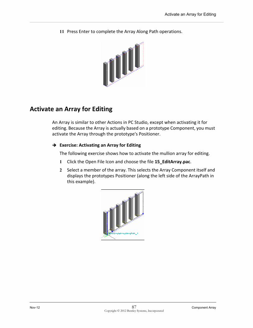
11 Press Enter to complete the Array Along Path operations.
Activate an Array for Editing
An Array is similar to other Actions in PC Studio, except when activating it for editing. Because the Array is actually based on a prototype Component, you must activate the Array through the prototype's Positioner.
Exercise: Activating an Array for Editing
The following exercise shows how to activate the mullion array for editing.
1 Click the Open File Icon and choose the file 15_EditArray.pac.
2 Select a member of the array. This selects the Array Component itself and displays the prototypes Positioner (along the left side of the ArrayPath in this example).
Nov-12 87 Component ArrayCopyright © 2012 Bentley Systems, Incorporated

Activate an Array for Editing
3 Selecting this Positioner will then activate the Array and display the Array Property Panel.
The Array operation has a number of options to help control the spacing and shape of the resulting array. These options are available in the Array Property Panel, which is shown below, and is displayed in the Folder pane (along the left of the screen) any time an Array Along Path is activated.
4 In the first box, which contains options for adjusting the Spacing of the Array Components, enter 1.000m in the Distance field. Qualify the Distance further by selecting At Most This Distance (a maximum distance
Component Array 88 Nov-12Copyright © 2012 Bentley Systems, Incorporated

Activate an Array for Editing
not to exceed), or At Least This Distance (a distance of not less than this value).
Note: Both the At Most and At Least spacing options create an even spacing of Components arrayed along the specified length of the Array.
5 In the First/Last Elements section, use the Drop First and Drop Last If At End options to create an Array of evenly spaced Components inside the extents of the lower edge.
6 Left-click into the view window to accept your entries.
Your mullion array should look like the image below.
7 Activate your frame solid to view the entire framework.
Nov-12 89 Component ArrayCopyright © 2012 Bentley Systems, Incorporated

Create an Array Along a Path
Create an Array Along a Path
Exercise: Creating an Array Along a Path
In this exercise, you will complete the window using the Array_GlassPanelComp component.
To complete the exercise, make sure the C:\PCS_Training folder is covered in your Library Path list in the Options dialog.
1 Click the Open File Icon and choose the file 16_GlassPanelArray.pac.
2 If not already attached, load the components of the C:\PCS_Training\ Library_Files directory (previous exercise).
3 Choose the Edit Snap Set tool, and add the blue InsideFramePath to the Snap Set.
4 From the Library_Files Library, right-click the Array_Glass component and select the Array Along Path command. You will be presented with the Component's Positioner and an Array Property Panel along the left side of the screen.
5 Place the Base Point PosGeom (the only one not grayed out) along an Edge of the Path as shown below, usually at the start vertex of the edge.
6 Use the Rotate option (R-key) to rotate the Component about its Axis to the desired orientation.
7 Click on the Extent Vertex PosGeom (usually the one furthest from the Base point) and drag it along the path to the lower right corner of the ArrayPath.
Component Array 90 Nov-12Copyright © 2012 Bentley Systems, Incorporated

Create an Array Along a Path
8 Right mouse click on the vertical dimension of the GlassPanelComp and choose the Delete option. The will free the Positioner determining the height of the GlassPanelComp.
9 Stretch the Positioner to mate the edge opposite the Base Point edge.
10 Press Enter to complete the Array Along Path operations.
Nov-12 91 Component ArrayCopyright © 2012 Bentley Systems, Incorporated

Create an Array Along a Path
11 Reactivate the Array and enter the values in the Array Property Panel as follows:
12 Left-click into the view window to accept your entries. Your GlassPanel array should look like the image below.
Component Array 92 Nov-12Copyright © 2012 Bentley Systems, Incorporated
Create an Array Along a Path
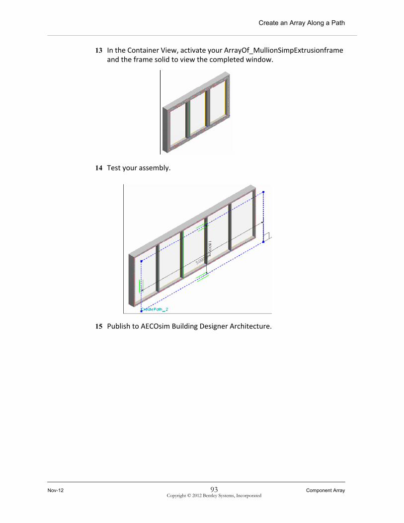
13 In the Container View, activate your ArrayOf_MullionSimpExtrusionframe and the frame solid to view the completed window.
14 Test your assembly.
15 Publish to AECOsim Building Designer Architecture.
Nov-12 93 Component ArrayCopyright © 2012 Bentley Systems, Incorporated

Create an Array Along a Path
Component Array 94 Nov-12Copyright © 2012 Bentley Systems, Incorporated