AECL, Licensing Submission, The Technology of …Project Projet SI Section Serial Série Sheet...
282
Licensing Submission Atomic Energy of Canada Limited 2251 Speakman Drive Mississauga, Ontario Canada L5K 1B2 Énergie Atomique du Canada Limitée 2251 rue Speakman Mississauga (Ontario) Canada L5K 1B2 Leger Marc Prepared by Rédigé par Prajapati Nandu Reviewed by Vérifié par Shalaby Basma Approved by Approuvé par THE TECHNOLOGY OF CANDU FUEL CHANNELS ACR USA 108US-31100-LS-001 Revision 0 2003/08/12 Controlled Licensing 2003/08/12 Contrôlé Licensing
Transcript of AECL, Licensing Submission, The Technology of …Project Projet SI Section Serial Série Sheet...

Licensing Submission
�Atomic Energy ofCanada Limited
2251 Speakman DriveMississauga, OntarioCanada L5K 1B2
�Énergie Atomique duCanada Limitée
2251 rue SpeakmanMississauga (Ontario)Canada L5K 1B2
Leger Marc
Prepared byRédigé par
Prajapati Nandu
Reviewed byVérifié par
Shalaby Basma
Approved byApprouvé par
THE TECHNOLOGY OFCANDU FUEL CHANNELS
ACR USA
108US-31100-LS-001
Revision 0
2003/08/12ControlledLicensing
2003/08/12ContrôléLicensing
SIGNATUREPAGE
DO NOT DELETE THIS!!!

108US-31100-LS-001 2003/08/12
Licensing Submission
The Technology of CANDU Fuel Channels
ACR USA
108US-31100-LS-001 Revision 0
2003 August
CONTROLLED - Licensing This document and the information contained in it is made available for licensing review. All rights reserved by Atomic Energy of Canada Limited. No part of this document may be reproduced or transmitted in any form or by any means, including photocopying and recording, without the written permission of the copyright holder, application for which should be addressed to Atomic Energy of Canada Limited. Such written permission must also be obtained before any part of this document is stored in a retrieval system of any nature.
Août 2003
CONTRÔLÉ - Permis Le présent document et l’information qu’il contient sont disponibles pour examen en vue de l’obtention des permis. Tous droits réservés par Énergie atomique du Canada limitée. Il est interdit de reproduire ou de transmettre, par quelque procédé que ce soit, y compris de photocopier ou d’enregistrer, toute partie du présent document, sans une autorisation écrite du propriétaire du copyright obtenue auprès d’Énergie atomique du Canada limitée. De plus, on doit obtenir une telle autorisation avant qu’une partie du présent document ne soit intégrée dans un système de recherche documentaire de quelque nature que ce soit.
� Atomic Energy of Canada Limited
© Énergie atomique du Canada limitée
2251 Speakman Drive Mississauga, Ontario Canada L5K 1B2
2251, rue Speakman Mississauga (Ontario) Canada L5K 1B2

Release and Liste des documents Revision History et des révisions 0939B Rev. 13
Document Details / Détails sur le document
Title Titre
Total no. of pages Nbre total de pages
The Technology of CANDU Fuel Channels
CONTROLLED – Licensing / CONTRÔLÉ - Permis
Release and Revision History / Liste des documents et des révisions
Release Document
Revision Révision
Purpose of Release; Details of Rev./Amendement Objet du document; détails des rév. ou des modif.
Prepared by Rédigé par
Reviewed by Examiné par
Approved by Approuvé par
No./No Date No./No Date
DCS/RMS Input / Données SCD ou SGD
Rel. Proj. Proj. conn.
Project Projet
SI
Section
Serial Série
Sheet Feuille No. N
o
Of De
Unit No.(s) Tranche no
108US 31100 LS 001 1 1 108US-31100-LS-001 2003/08/12 dsfpdfmb
1 D1 2003/07/14 Draft Issued for Review and Comment.
M. Léger N. Prajapati C. Parkinson L. Dimitrov V.G. Snell D.J. Wren M.P. Puls M. Bonechi Z. Bilanovic D.K. Rodgers
2 0 2003/08/12 Issued as “Approved for Use.” M. Léger N. Prajapati B.A. Shalaby
CONTROLLED - Licensing 108US-31100-LS-001 Page i Rev. 0
108US-31100-LS-001 2003/08/12
AUTHORSHIP AND ACKNOWLEDGEMENT This document is an updated document prepared using input from many authors throughout AECL. Indebtedness is acknowledged to the following for their contributions: A.M. Babayan, N. Badie, A.A. Bahurmuz, C.K. Chow, N. Christodoulou, W.R. Clendening, A.J. Elliot, I. Inglis, I.J. Muir, E.V. Murphy, H.M. Nordin, L.P. Nosella, M.P. Puls, D.K. Rodgers, S. St. Lawrence, J.R. Theaker, G. Van Drunen and A. Villamagna

CONTROLLED - Licensing 108US-31100-LS-001 Page ii Rev. 0
TABLE OF CONTENTS
SECTION PAGE
108US-31100-LS-001 2003/08/12
1. INTRODUCTION TO THE FUEL CHANNEL AND THE CANDU SYSTEM ..............................................................................................................1-1
1.1 Purpose of this Document ....................................................................................1-1 1.2 Abbreviations, Acronyms and Terminology........................................................1-1 1.3 The CANDU Reactor ...........................................................................................1-3 1.4 On Power Fuelling ...............................................................................................1-4 1.5 Materials...............................................................................................................1-5 1.6 Evolution of Fuel Channel Design .......................................................................1-5 1.7 General Features of Fuel Channels ......................................................................1-6
2. FUEL CHANNEL DESIGN REQUIREMENTS ................................................2-1
2.1 Introduction ..........................................................................................................2-1 2.2 Functional Requirements......................................................................................2-1 2.3 Performance Requirements ..................................................................................2-1 2.3.1 Requirements from Reactor Physics ..............................................................2-1 2.3.2 Requirements from the Heat Transport System .............................................2-2 2.3.3 Requirements from Fuel Handling.................................................................2-2 2.3.4 Requirements from the Annulus Gas System ................................................2-3 2.4 Safety Requirements ............................................................................................2-3 2.5 Seismic Requirements ..........................................................................................2-4 2.6 Codes and Standards ............................................................................................2-4 2.7 Materials Requirements........................................................................................2-5 2.7.1 Corrosion and Wear Allowances....................................................................2-5 2.7.2 Allowance for the Effect of Environment on Material Properties .................2-5 2.7.2.1 Creep and Growth Deformation...............................................................2-5 2.7.2.2 Delayed Hydride Cracking.......................................................................2-6 2.8 Reliability and Maintainability Requirements .....................................................2-6 2.9 Inspection and Testing Requirements ..................................................................2-7 2.9.1 Testing............................................................................................................2-7 2.9.2 Inspection .......................................................................................................2-7 2.10 Decontamination and Decommissioning Requirements ......................................2-7 2.11 Interfacing Systems Requirements.......................................................................2-7 2.11.1 Heat Transport System...................................................................................2-8 2.11.2 Fuel.................................................................................................................2-8 2.11.3 Fuel Handling System ....................................................................................2-8 2.11.4 Moderator System ..........................................................................................2-9 2.11.5 Reactor Structure............................................................................................2-9 2.11.6 Reactivity Control Units.................................................................................2-9 2.11.7 Annulus Gas System ......................................................................................2-9
3. FUEL CHANNEL DESIGN DESCRIPTION .....................................................3-1
3.1 Introduction ..........................................................................................................3-1

CONTROLLED - Licensing 108US-31100-LS-001 Page iii Rev. 0
TABLE OF CONTENTS
SECTION PAGE
108US-31100-LS-001 2003/08/12
3.2 Fuel Channel Components ...................................................................................3-1 3.2.1 Pressure Tubes................................................................................................3-1 3.2.2 Pressure Tube to End Fitting Rolled Joint .....................................................3-3 3.2.3 End Fittings ....................................................................................................3-4 3.2.4 Calandria Tubes..............................................................................................3-5 3.2.5 Annulus Spacers.............................................................................................3-5 3.2.6 Bellows...........................................................................................................3-6 3.3 Analyses ...............................................................................................................3-6 3.4 Operating Conditions for the Fuel Channels in the Existing CANDU
Commercial Power Reactors and Changes for ACR ...........................................3-7 3.4.1 Pressure Distribution ......................................................................................3-7 3.4.2 Temperature Distribution ...............................................................................3-7 3.4.3 Flux Profile.....................................................................................................3-8 3.4.4 Heat Transport Fluid ......................................................................................3-8 3.4.5 Coolant Chemistry..........................................................................................3-8 3.4.6 Cooldown Rate...............................................................................................3-8 3.5 Design Documentation.........................................................................................3-8
4. CODES AND STANDARDS FOR THE DESIGN AND FABRICATION OF FUEL CHANNELS .......................................................................................4-1
4.1 Introduction ..........................................................................................................4-1 4.2 CAN/CSA-N285.0, General Requirements .........................................................4-2 4.3 CAN/CSA-N285.2, Requirements for Class 1C, 2C and 3C
Pressure-Retaining Components ..........................................................................4-3 4.3.1 Pressure Tube to End Fitting Joints................................................................4-4 4.3.2 Pressure Tubes................................................................................................4-5 4.3.3 Channel Closure .............................................................................................4-6 4.4 CAN/CSA-N285.6, Material Standards for Reactor Components.......................4-6 4.4.1 N285.6.1, Seamless Zirconium Alloy Tubing for Fuel Channels
(Pressure Tubes).............................................................................................4-7 4.4.2 N285.6.8, Material Requirements for End Fittings........................................4-8 4.4.3 N285.6.4, Thin Walled, Large Diameter Zirconium Alloy Tubing
(Calandria Tubes)...........................................................................................4-8 4.5 Summary ..............................................................................................................4-8
5. MATERIALS FOR THE FUEL CHANNEL ASSEMBLIES.............................5-1
5.1 Introduction ..........................................................................................................5-1 5.2 Material Microstructures ......................................................................................5-1 5.2.1 Pressure Tubes................................................................................................5-2 5.2.2 Calandria Tubes..............................................................................................5-2 5.2.3 Spacers ...........................................................................................................5-3 5.2.4 End Fittings ....................................................................................................5-3

CONTROLLED - Licensing 108US-31100-LS-001 Page iv Rev. 0
TABLE OF CONTENTS
SECTION PAGE
108US-31100-LS-001 2003/08/12
5.3 Mechanical Properties ..........................................................................................5-3 5.3.1 Design Stress Intensity and Mechanical Properties .......................................5-3 5.4 Physical Properties ...............................................................................................5-3 5.4.1 Elastic Modulus, Shear Modulus and Poisson’s Ratio...................................5-3 5.4.2 Thermal Conductivity ....................................................................................5-3 5.4.3 Thermal Expansion ........................................................................................5-3 5.5 References ............................................................................................................5-4
6. MANUFACTURE OF PRESSURE TUBES.......................................................6-1
6.1 Background ..........................................................................................................6-1 6.2 Steps in Pressure Tube Fabrication ......................................................................6-1 6.2.1 Ingot ...............................................................................................................6-2 6.2.2 Billets .............................................................................................................6-3 6.2.3 Extrusion Hollows..........................................................................................6-4 6.2.4 Cold Drawn Tubes .........................................................................................6-4 6.2.5 Finished Tubes ...............................................................................................6-4 6.3 Design Responsibility ..........................................................................................6-5 6.4 Fabrication Process and Metallurgical Requirements..........................................6-5 6.5 Quality Assurance ................................................................................................6-6 6.6 Audit Procedures ..................................................................................................6-7 6.7 Procurement Engineering.....................................................................................6-7 6.8 Qualification of Production Changes ...................................................................6-8 6.9 Long Term Developments....................................................................................6-8 6.10 References ............................................................................................................6-8
7. DEVELOPMENTAL BASIS FOR PRESSURE TUBE ROLLED JOINT DESIGN ...............................................................................................................7-1
7.1 Introduction ..........................................................................................................7-1 7.1.1 Available Joint Techniques ............................................................................7-1 7.1.2 Rolled Joints - Background............................................................................7-1 7.2 Rolled Joint Technology (Pressure Tube to End Fitting Rolled Joints)...............7-2 7.2.1 Rolling Tool (Tube Expander) .......................................................................7-2 7.2.2 Development of the Stress Field Between the Pressure Tube and End
Fitting During Roll Expansion .......................................................................7-3 7.2.3 Characteristics of the CANDU Pressure Tube to End Fitting Rolled
Joints...............................................................................................................7-4 7.3 Design Philosophy................................................................................................7-5 7.3.1 Design Assurance by Component Testing .....................................................7-6 7.3.2 Applicable Codes and Standards....................................................................7-6 7.4 Rolled Joint Test Programs ..................................................................................7-6 7.4.1 Material Constraints .......................................................................................7-7 7.4.2 Dimensional Limits ........................................................................................7-7

CONTROLLED - Licensing 108US-31100-LS-001 Page v Rev. 0
TABLE OF CONTENTS
SECTION PAGE
108US-31100-LS-001 2003/08/12
7.4.2.1 Pressure Tubes..........................................................................................7-7 7.4.2.2 End Fitting Assemblies ............................................................................7-7 7.4.3 Load Conditions .............................................................................................7-7 7.4.4 Temperature Conditions.................................................................................7-8 7.4.5 Fabrication Constraints ..................................................................................7-8 7.5 Component Development Testing by Stages .......................................................7-8 7.5.1 Feasibility Tests..............................................................................................7-8 7.5.2 Development Tests.........................................................................................7-8 7.5.3 Qualification Tests .........................................................................................7-9 7.5.4 Primary Constituents of a Rolled Joint Program............................................7-9 7.6 Test Details...........................................................................................................7-9 7.6.1 Procurement of Components..........................................................................7-9 7.6.2 Receiving Inspection and Component Matching .........................................7-10 7.6.3 Rolled Joint Fabrication ...............................................................................7-10 7.6.3.1 Definition of Fabrication Variables........................................................7-11 7.6.3.2 Observations and Output Data ...............................................................7-11 7.6.3.3 Fabrication..............................................................................................7-11 7.6.4 Dimensional Measurements .........................................................................7-11 7.6.5 Helium Leak Tests .......................................................................................7-12 7.6.6 Residual Stress Measurements - End Fitting................................................7-13 7.6.7 Residual Stress Measurements - Pressure Tube...........................................7-13 7.6.8 Hot Pressurized Pullout Test ........................................................................7-13 7.6.9 Metallographic Evaluation of Hydride Distribution ....................................7-14 7.6.10 Long-Term Thermal Fatigue Tests ..............................................................7-14 7.7 Documentation ...................................................................................................7-14 7.8 Creep and Stress Relaxation...............................................................................7-14 7.9 Post-Service Examination and Testing of the Rolled Joints ..............................7-14 7.10 Testing of Other Roll Expanded Joints in the Fuel Channel..............................7-15 7.11 Conclusion..........................................................................................................7-15 7.12 References ..........................................................................................................7-15
8. FUEL CHANNEL DEFORMATION UNDER IRRADIATION........................8-1
8.1 Introduction ..........................................................................................................8-1 8.2 Deformation Mechanisms ....................................................................................8-2 8.3 Irradiation Creep ..................................................................................................8-2 8.3.1 Effect of Operating Variables ........................................................................8-3 8.3.2 Effect of Metallurgical Variables...................................................................8-4 8.4 Irradiation Growth................................................................................................8-5 8.4.1 Effect of Operating Variables ........................................................................8-5 8.4.2 Effect of Metallurgical Variables...................................................................8-7 8.5 Constitutive Equations .........................................................................................8-8 8.5.1 Form of the Equations ....................................................................................8-8 8.5.2 Pressure Tube Equation................................................................................8-10

CONTROLLED - Licensing 108US-31100-LS-001 Page vi Rev. 0
TABLE OF CONTENTS
SECTION PAGE
108US-31100-LS-001 2003/08/12
8.5.3 Calandria Tube Equation..............................................................................8-12 8.6 Comparison of Equations with Databases..........................................................8-14 8.6.1 Pressure Tube Equation................................................................................8-14 8.6.2 Calandria Tube Equation..............................................................................8-15 8.7 Creep Ductility ...................................................................................................8-15 8.8 Deformation Codes ............................................................................................8-16 8.8.1 Modeling of the Sag of Fuel Channels.........................................................8-16 8.9 Summary ............................................................................................................8-19 8.10 References ..........................................................................................................8-20
9. CORROSION AND HYDROGEN INGRESS....................................................9-1
9.1 Introduction ..........................................................................................................9-1 9.2 Pressure Tube Corrosion and Hydrogen Ingress..................................................9-2 9.2.1 Waterside Corrosion and Hydrogen Ingress ..................................................9-2 9.2.2 In-Reactor Loop Tests to Study Corrosion and Hydrogen Ingress into
Zr-2.5Nb.........................................................................................................9-4 9.2.2.1 The Pressure Tube Hydrogen Ingress Model...........................................9-4 9.2.2.2 Development of Improved Pressure Tubes ..............................................9-6 9.2.3 Annulus Gas Side Corrosion and Hydrogen Ingress......................................9-8 9.2.4 Summary of Pressure Tube Corrosion and Hydrogen Ingress .......................9-9 9.3 Hydrogen Ingress at Rolled Joints .......................................................................9-9 9.3.1 Background ....................................................................................................9-9 9.3.2 Mechanisms of Hydrogen Ingress at Rolled Joints......................................9-10 9.3.2.1 Sources and Routes of Hydrogen Ingress ..............................................9-10 9.3.3 Modeling Hydrogen Build-up at Rolled Joints ............................................9-11 9.3.3.1 Model Development...............................................................................9-11 9.3.3.2 Model Predictions ..................................................................................9-11 9.3.4 Summary of Hydrogen Ingress at Rolled Joints...........................................9-12 9.4 References ..........................................................................................................9-14
10. MECHANICAL PROPERTY CHANGES OF PRESSURE TUBES DURING SERVICE...........................................................................................10-1
10.1 Introduction ........................................................................................................10-1 10.2 Material ..............................................................................................................10-1 10.3 Tensile Properties...............................................................................................10-1 10.3.1 Transverse Direction ....................................................................................10-2 10.3.1.1 Unirradiated Tensile Properties..............................................................10-2 10.3.1.2 Irradiated Tensile Properties ..................................................................10-2 10.3.1.2.1 Effect of Fluence ..............................................................................10-2 10.3.1.2.2 Effect of Irradiation Temperature ....................................................10-2 10.3.1.2.3 Effect of Test Temperature ..............................................................10-3 10.3.2 Axial Direction.............................................................................................10-3

CONTROLLED - Licensing 108US-31100-LS-001 Page vii Rev. 0
TABLE OF CONTENTS
SECTION PAGE
108US-31100-LS-001 2003/08/12
10.3.2.1 Unirradiated Tensile Properties..............................................................10-3 10.3.2.2 Irradiated Tensile Properties ..................................................................10-3 10.3.3 Summary ......................................................................................................10-3 10.4 Fracture Toughness ............................................................................................10-3 10.4.1 Test Methods ................................................................................................10-4 10.4.2 Results ..........................................................................................................10-5 10.4.2.1 Small Specimens ....................................................................................10-5 10.4.2.2 Effect of Impurities ................................................................................10-5 10.4.2.3 Effect of Test Temperature ....................................................................10-5 10.4.2.4 Effect of Fluence ....................................................................................10-6 10.4.3 Rising-Pressure Burst Tests .........................................................................10-6 10.4.3.1 Factors Affecting Burst Fracture Toughness .........................................10-6 10.4.3.2 Summary ................................................................................................10-6 10.5 References ..........................................................................................................10-7
11. INSPECTION AND MONITORING OF CANDU FUEL CHANNELS .........11-1
11.1 Inspection Programs...........................................................................................11-1 11.2 Fuel Channel Inspection and Monitoring Methods............................................11-1 11.2.1 Summary ......................................................................................................11-1 11.2.2 Pressure Tube Flaw Detection and Characterization ...................................11-2 11.2.2.1 Volumetric Inspection Methods .............................................................11-2 11.2.2.2 Surface Flaw Characterization ...............................................................11-4 11.2.3 Monitoring Pressure Tube Geometry...........................................................11-4 11.2.3.1 Diameter and Wall Thickness Measurement .........................................11-5 11.2.3.2 Sag Measurement ...................................................................................11-5 11.2.3.3 Pressure Tube Elongation.......................................................................11-5 11.2.4 Structural and Material Changes ..................................................................11-6 11.2.4.1 Spacers ...................................................................................................11-6 11.2.4.2 Pressure Tube to Calandria Tube Contact..............................................11-6 11.2.4.3 Pressure Tube to Calandria Tube Gap....................................................11-7 11.2.4.4 Hydrogen Measurement .........................................................................11-7 11.2.4.5 Material Surveillance .............................................................................11-7 11.2.5 Calandria Tube Geometry ............................................................................11-8 11.2.5.1 Calandria Tube Dimensional Gauging and Inspection ..........................11-8 11.2.5.2 Calandria Tube Elongation.....................................................................11-8 11.2.6 Leak Location...............................................................................................11-9 11.3 Multifunctional Fuel Channel Inspection Systems ..........................................11-10 11.3.1 Dry Channel Inspection Equipment ...........................................................11-10 11.3.2 CIGAR .......................................................................................................11-10 11.3.3 AFCIS.........................................................................................................11-11 11.3.4 ANDE.........................................................................................................11-12 11.3.5 Special Purpose Inspection Systems ..........................................................11-12 11.4 Fuel Channel Inspection in ACR .....................................................................11-13

CONTROLLED - Licensing 108US-31100-LS-001 Page viii Rev. 0
TABLE OF CONTENTS
SECTION PAGE
108US-31100-LS-001 2003/08/12
11.5 Summary ..........................................................................................................11-13 11.6 References ........................................................................................................11-14
12. APPLICATION OF LEAK BEFORE-BREAK PRINCIPLES TO THE PRESSURE TUBES OF CANDU REACTORS ...............................................12-1
12.1 Introduction ........................................................................................................12-1 12.2 Delayed Hydride Cracking.................................................................................12-2 12.2.1 Conditions for DHC Initiation......................................................................12-3 12.2.1.1 TSS.........................................................................................................12-3 12.2.1.2 Threshold Stress on Smooth Surface .....................................................12-4 12.2.1.3 KIH ..........................................................................................................12-4 12.2.2 DHC Velocity...............................................................................................12-5 12.2.2.1 Effect of Irradiation................................................................................12-5 12.2.2.2 Effect of Test Temperature ....................................................................12-5 12.2.3 Procedures to Avoid DHC ...........................................................................12-5 12.2.4 Summary of Delayed Hydride Cracking......................................................12-6 12.3 Leak-before Break Analysis...............................................................................12-6 12.3.1 Sequence-of-Events Analysis Inputs............................................................12-6 12.3.2 Sequence-of-Events Analysis Results..........................................................12-8 12.3.3 Conservatism and Uncertainty in the Analysis ............................................12-8 12.4 References ..........................................................................................................12-8
13. PRESSURE TUBE FAILURE EXPERIENCE .................................................13-1
13.1 Introduction ........................................................................................................13-1 13.1.1 Experience in CANDU with Zircaloy Pressure Tubes.................................13-1 13.1.2 Experience in CANDU with Zr-2.5Nb Pressure Tubes ...............................13-2 13.2 Reliability of Pressure Tubes to Date.................................................................13-3 13.3 Predicted Future Reliability of Pressure Tubes in the CANDU Reactors..........13-4 13.4 References ..........................................................................................................13-5
14. FUEL CHANNEL REPLACEMENT................................................................14-1
14.1 Introduction ........................................................................................................14-1 14.2 Overview of Fuel Channel Replacement ...........................................................14-1 14.2.1 In-Service Inspection....................................................................................14-1 14.2.2 Individual (Single) Fuel Channel Replacement ...........................................14-1 14.2.3 Large Scale Fuel Channel Replacement.......................................................14-2 14.3 Fuel Channel Replacement Process ...................................................................14-3 14.3.1 Single Channel Replacement .......................................................................14-3 14.3.2 Large Scale Fuel Channel Replacement.......................................................14-4 14.4 ACR Large Scale Fuel Channel Replacement ...................................................14-5 14.5 Summary ............................................................................................................14-6

CONTROLLED - Licensing 108US-31100-LS-001 Page ix Rev. 0
TABLE OF CONTENTS
SECTION PAGE
108US-31100-LS-001 2003/08/12
15. END FITTING PROPERTIES AND PERFORMANCE ..................................15-1
15.1 Introduction ........................................................................................................15-1 15.2 Fabrication..........................................................................................................15-2 15.2.1 Steelmaking Practice ....................................................................................15-2 15.2.2 Forging and Heat Treatment ........................................................................15-2 15.2.3 Final Machining ...........................................................................................15-2 15.3 Material Property Data .......................................................................................15-3 15.3.1 Requirements................................................................................................15-3 15.3.1.1 Tensile Properties at Room Temperature (21°C (70°F) Max.) ..............15-3 15.3.1.2 Charpy V-Notch Impact Property Requirements ...................................15-3 15.3.1.3 Hardness Requirements..........................................................................15-3 15.3.2 Effect of Irradiation on Mechanical Properties ............................................15-4 15.3.2.1 Tensile Properties...................................................................................15-4 15.3.2.2 Impact Properties....................................................................................15-4 15.3.3 Fatigue..........................................................................................................15-4 15.4 Charpy Impact Test Data with respect to Code Requirements ..........................15-5 15.5 AECL Approach to Ensure Against Brittle Fracture .........................................15-5 15.6 Assessment of Possible Damage Mechanisms...................................................15-6 15.6.1 Introduction ..................................................................................................15-6 15.6.2 Wear .............................................................................................................15-6 15.6.3 General Corrosion ........................................................................................15-6 15.6.4 Flow Accelerated Corrosion.........................................................................15-6 15.6.5 Localized Corrosion .....................................................................................15-7 15.7 Summary ............................................................................................................15-7 15.8 References ..........................................................................................................15-7
16. CALANDRIA TUBE PERFORMANCE ..........................................................16-1
16.1 Introduction ........................................................................................................16-1 16.2 The Unirradiated Tubes......................................................................................16-1 16.2.1 Fabrication....................................................................................................16-1 16.2.2 Uniaxial Strength..........................................................................................16-2 16.2.3 Biaxial Strength – Unirradiated....................................................................16-3 16.3 The Irradiated Tubes ..........................................................................................16-3 16.3.1 Uniaxial Strength..........................................................................................16-3 16.3.2 Biaxial Strength............................................................................................16-3 16.4 In-Reactor Deformation .....................................................................................16-4 16.4.1 Creep Resistance ..........................................................................................16-4 16.4.2 Irradiation Growth........................................................................................16-4 16.5 Resistance to Crack Growth...............................................................................16-4 16.5.1 Potential Failure Mechanisms ......................................................................16-4 16.5.2 Delayed Hydride Cracking...........................................................................16-5 16.5.3 Fatigue..........................................................................................................16-5
CONTROLLED - Licensing 108US-31100-LS-001 Page x Rev. 0
TABLE OF CONTENTS
SECTION PAGE
108US-31100-LS-001 2003/08/12
16.6 Reactor Experience ............................................................................................16-5 16.7 Summary and Conclusions.................................................................................16-6 16.8 References ..........................................................................................................16-6
17. FUEL CHANNEL ANNULUS SPACERS .......................................................17-1
17.1 Introduction ........................................................................................................17-1 17.2 Material and Design ...........................................................................................17-2 17.3 Qualification Testing..........................................................................................17-3 17.3.1 Spacer Radial Compression Tests ................................................................17-3 17.3.2 Spacer Wear/Endurance Tests......................................................................17-3 17.3.3 Channel Vibration Tests...............................................................................17-4 17.4 Post-Service Testing of Inconel X-750 Spacers.................................................17-5 17.4.1 Stretch Tests .................................................................................................17-5 17.4.2 Radial Compression Tests............................................................................17-5 17.4.3 Wear/Endurance Tests..................................................................................17-6 17.5 Conclusions ........................................................................................................17-6 17.6 References ..........................................................................................................17-7
18. LIFE LIMITING CONSIDERATIONS IN FUEL CHANNEL COMPONENTS.................................................................................................18-1
18.1 Introduction ........................................................................................................18-1 18.2 Pressure Tubes....................................................................................................18-1 18.2.1 Stress Limits.................................................................................................18-1 18.2.2 Dimensional Limits ......................................................................................18-1 18.2.3 Pressure Tube Integrity ................................................................................18-2 18.3 Calandria Tubes..................................................................................................18-4 18.4 End Fittings ........................................................................................................18-4 18.5 Garter Spring Spacers.........................................................................................18-5 18.6 Summary ............................................................................................................18-5
TABLES
Table 5-1(a) Design Stress Values for Pressure Tube, Calandria Tube, Spacer and End Fitting Materials ...................................................................................................5-5
Table 5-1(b) Ultimate Tensile Strength (UTS) and Yield Strength (YS) Values for End Fitting Material.....................................................................................................5-6
Table 5-2 Elastic Moduli Values for Pressure Tube, Calandria Tube, Spacer and End Fitting Materials ...................................................................................................5-7
Table 5-3 Thermal Conductivity Data for Pressure Tube, Calandria Tube, Spacer and End Fitting Materials............................................................................................5-8

CONTROLLED - Licensing 108US-31100-LS-001 Page xi Rev. 0
TABLE OF CONTENTS
SECTION PAGE
108US-31100-LS-001 2003/08/12
Table 5-4(a) Thermal Expansion Data for Pressure Tube, Calandria Tube, and Spacer Materials...............................................................................................................5-9
Table 5-4(b) Thermal Expansion Data for End Fitting Material.............................................5-10
Table 6-1 Quality Program Manufacture and Processing of Pressure Tubes.....................6-10
Table 11-1 Summary of Minimum Code* Inspection Requirements for CANDU Fuel Channels ...........................................................................................................11-16
Table 13-1 Pressure Tube Failures .......................................................................................13-6
Table 13-2 Operating History of Pressure Tubes (to the end of 2001) ................................13-7
Table 13-3 Fuel Channel Integrity Problems Experienced in CANDU Reactors and Solutions.............................................................................................................13-9
Table 15-1 Room Temperature Tensile Properties of Quenched and Tempered AISI Type 403/410 Stainless Steel .............................................................................15-9
Table 15-2 Transition Temperature Shifts for AISI 403 SS Based on Transverse Charpy Specimens [Reference 15.2] ................................................................15-10
Table 15-3 Recent Charpy Impact Ductility (MLE) Results for AISI Type 403 End Fitting Steels.....................................................................................................15-11
Table 15-4 Burst Pressures of Slotted End Fittings at -40°C .............................................15-11
Table 16-1 Burst Test Results on Two Unirradiated Calandria Tubes in the Fixed End Mode at a Strain Rate of 10-3 s-1.........................................................................16-8
Table 16-2 Tensile Properties of the Calandria Tube Removed from Operating CANDU Reactors...............................................................................................16-8
Table 16-3 Properties of Calandria Tubes Burst in a Fixed End Condition at 170°C..........16-9 Table 17-1 Summary of Mechanical Tests Performed on Inconel Garter Springs
Removed from NPD...........................................................................................17-8
Table 17-2 Summary of Stretch Test Results .......................................................................17-8
Table 17-3 Summary of Rising-Load Compression Tests on NPD Fuel Channel Annulus Spacers.................................................................................................17-9
Table 17-4 Radial Compression Fatigue Testing Sequence for Segments of an Unirradiated NPD Spring and Springs from NPD Fuel Channels C08 and K05.....................................................................................................................17-9
Table 17-5 Radial Compression Fatigue Testing Sequence for Spring Segments from NPD Fuel Channels G07 and F08 ....................................................................17-10
Table 17-6 Summary of Radial Compression Fatigue Testing Results..............................17-10

CONTROLLED - Licensing 108US-31100-LS-001 Page xii Rev. 0
TABLE OF CONTENTS
SECTION PAGE
108US-31100-LS-001 2003/08/12
Table 17-7 Diameter of Garter Springs from Two NPD Fuel Channels Before and After Wear/Endurance Testing.........................................................................17-11
FIGURES
Figure 1-1 An Illustration of a CANDU Reactor Showing the Calandria Vessel, the Fuel Channels, Feeders and Vertical and Horizontal Reactivity Mechanisms ........................................................................................1-8
Figure 1-2 The ACR Calandria and Shield Tank Assembly..................................................1-9
Figure 1-3 The Face of a CANDU-6 Reactor as seen during Construction ........................1-10
Figure 1-4 CANDU Reactor Simplified Flow Diagram. In ACR the coolant is light water and the fuel is SEU...........................................................................1-11
Figure 1-5 A CANDU Fuel Bundle .....................................................................................1-12
Figure 1-6 Details of the CANDU-6 Fuel Channel .............................................................1-13
Figure 1-7 The ACR Fuel Channel ......................................................................................1-14
Figure 3-1 Schematic of a Fuel Channel in a CANDU Reactor ............................................3-9
Figure 3-2 Pressure and Temperature Variation Trends along the Length of a Fuel Channel and their Influence on the Required Wall Thickness.....................3-9
Figure 3-3 Typical Pressure Tube to End Fitting Rolled Joint ............................................3-10
Figure 3-4 Schematic of an Installed Calandria Tube for Current Reactors........................3-10
Figure 6–1 Simplified Flow Chart for CANDU Pressure Tube Manufacture......................6-11
Figure 7–1 Typical Pressure Tube to End Fitting Rolled Joint ............................................7-17
Figure 7–2 Qualification Process for Changes to Rolled Joint.............................................7-18
Figure 7–3 Stages in a Rolled Joint Test Program ...............................................................7-19
Figure 7–4 Three Stages of Rolled Joint Experimental Design ...........................................7-20
Figure 7–5 Primary Constituents of a Rolled Joint Test Program........................................7-21
Figure 7–6 A Histogram of Hot (300°C), Pressurized, Pull Out Test Results .....................7-22 Figure 8–1 Temperature Dependence for Creep for Different Zirconium
Alloys .................................................................................................................8-24
Figure 8–2 Temperature Dependence of Irradiation Creep of Cold-worked Zr-2.5Nb Pressure Tube Material (from [8.10]) ................................................8-25
Figure 8–3 Stress Dependence of In-reactor Creep of Zirconium Alloys at ~ 300°C (Schematic) .............................................................................................8-25
CONTROLLED - Licensing 108US-31100-LS-001 Page xiii Rev. 0
TABLE OF CONTENTS
SECTION PAGE
108US-31100-LS-001 2003/08/12
Figure 8–4 Strain Rate as a Function of Hoop Stress for Internally Pressurized Capsules Irradiated in the Osiris Reactor (from [8.14]).....................................8-26
Figure 8–5 Stress Dependence of the In-reactor Creep Rate of Cold-worked Pressure Tube Material at 300°C and over a Range of Applied Stresses (from [8.10]).........................................................................................8-27
Figure 8–6 Effect of Temperature on the Stress Dependence of Creep of Cold-worked Zr-2.5Nb Pressure Tubes (from [8.10]) .......................................8-27
Figure 8–7 Variation of the Creep Constant, Kc, with Dislocation Density.........................8-28
Figure 8–8 Effect of Grain Size on Creep of Zirconium Alloys ..........................................8-29
Figure 8–9 Irradiation Growth of Zircaloy-2 Sheet at 60°C Showing Dependence on Texture. Material 199-K slowly cooled from 800°C; material 199-V rapidly cooled from 1020°C .........................................8-30
Figure 8–10 Irradiation Growth of Recrystallized Zircaloy-2 at 60°C Showing Dependence of Longitudinal Strain on Texture in the Normal-Transverse Plane...................................................................................8-31
Figure 8–11 Irradiation Growth in Annealed Zircaloy-2 at 280 to 310°C Showing Accelerating Growth at 4 × 1025 n/m2, E > 1 MeV.............................8-31
Figure 8–12 Irradiation Growth of Annealed and Cold-worked/Stress Relieved Zr-2.5Nb.............................................................................................................8-32
Figure 8–13 Irradiation Growth of Longitudinal and Transverse Specimens of a Darlington Tube Irradiated in Trillium 2 and 3 in Osiris...................................8-33
Figure 8–14 Irradiation Growth of Longitudinal Specimens of a Bruce B Tube Pre-irradiated in Dido and a Bruce A Tube Pre-irradiated in Bruce Unit 2 before Irradiation in Trillium 2 in Osiris.................................................8-33
Figure 8–15 Steady-state Irradiation of Zircaloy-2 at 60°C as a Function of Dislocation Density. The numbers beside each data point denote the ratio of <c> to <a> component dislocations.................................................8-34
Figure 8–16 Comparison of Measured and Predicted Transverse Strain Rates for the Axial Profiles of Pressure Tubes in Pickering Unit 3 and a CANDU 6 Reactor. Note that one of the Pickering 3 tubes and the CANDU 6 tubes have the back in the outlet, while the other Pickering 3 tube has the back end in the inlet. ...................................................8-34
Figure 8–17 Comparison of Measured vs. Predicted Diametral Strain Rate from Tubes in a CANDU 6, an OPG 480-channel CANDU and Pickering 3 Units................................................................................................8-35

CONTROLLED - Licensing 108US-31100-LS-001 Page xiv Rev. 0
TABLE OF CONTENTS
SECTION PAGE
108US-31100-LS-001 2003/08/12
Figure 8–18 Elongation Data from a CANDU 6 Reactor. The predicted elongation was derived using the pressure tube equation described in Subsection 8.4.2. ............................................................................................8-35
Figure 8–19 A Plot of the Stress Exponent n against Total Elongation at Failure for Zirconium Alloys at 300 to 450°C. The hatched band is for the results from tensile tests on many other alloys (from [8.47]). ...........................8-36
Figure 8–20 Typical CDEPTH Model for Calculation of Fuel Channel Sag Response.............................................................................................................8-36
Figure 8–21 Typical 3D Model for Calculation of Fuel Channel Deformation (spacers are not seen as they are modeled using contact elements) ...................8-37
Figure 8–22 Comparison of Measured Sag for Pickering 3 Tube J17 with Calculated Behavior Using the Pressure Tube and Calandria Tube Equations Described in Subsections 8.5.2 and 8.5.3..........................................8-37
Figure 8–23 Comparison of Measured Sag for Pickering 3 Tube M12 with Calculated Behavior Using the Pressure Tube and Calandria Tube Equations Described in Subsections 8.5.2 and 8.5.3..........................................8-38
Figure 8–24 Comparison of Measured Pressure Tube Sag in a Tube in Bruce NGS-A Unit 2 after 54,800 Hours with the Sag Calculated Using CDEPTH ............................................................................................................8-38
Figure 8–25 Comparison of Measured Pressure Tube Curvature in a Tube in Bruce NGS-A Unit 2 after 54,800 Hours with the Curvature Calculated Using CDEPTH................................................................................8-39
Figure 8–26 Comparison of Measured with Predicted Gap Obtained from a CANDU 6 Tube after 124,800 Hours ................................................................8-39
Figure 9-1 A Schematic Diagram of a CANDU Fuel Channel Showing Details of the Pressure Tube, End Fitting and Rolled Joint, and the Annulus Gas Space.............................................................................................9-16
Figure 9-2 A Typical Deuterium Concentration Profile along a Pressure Tube in a CANDU Reactor (after 14 EFPY of Operation). The flux and temperature profiles along the pressure tube are also shown.............................9-16
Figure 9-3 The Measured Deuterium Concentration in Zr-2.5Nb Surveillance Pressure Tubes near the Outlet of the Fuel Channel as a Function of Time ...............................................................................................................9-17
Figure 9-4 The Measured Oxide Thickness on the Inside of Zr-2.5Nb Surveillance Pressure Tubes near the Outlet of the Fuel Channel as a Function of Time14 ..........................................................................................9-17

CONTROLLED - Licensing 108US-31100-LS-001 Page xv Rev. 0
TABLE OF CONTENTS
SECTION PAGE
108US-31100-LS-001 2003/08/12
Figure 9-5 An Arrhenius Plot of the Deuterium Uptake for Pressure Tubes in a CANDU 6 Reactor ..........................................................................................9-18
Figure 9-6 The Rate of Oxide Growth on Zr-2.5Nb Coupons as a Function of Surface Oxide Thickness. Coupons exposed at ~300°C in light water U-2 Loop, NRU Reactor, at a pH ~10.2. The dissolved hydrogen concentration was either 5, 25 or 50 ml/kg. Oxide growth rates near or below zero are indicative of the spalling of the surface oxide from the coupon. ..........................................................................9-19
Figure 9-7 Predicted and Measured Deuterium Concentration along a Pressure Tube as a Function of Time. Model predictions are normalized to the 13 Hot Year data (the 9 Hot Year data at > 5 m are considered erroneous)...........................................................................................................9-20
Figure 9-8 Predicted and Measured Deuterium Uptake as a Function of Time at the Outlet End [T=307oC, Flux=2.0x10¹⁷ n/m2.s] ..........................................9-20
Figure 9-9 Deuterium Uptake Curves as a Function of Iron and Carbon Concentrations in Zr-2.5Nb Drop Castings Corroded In-flux for 450 Days at 325°C in D2O .................................................................................9-21
Figure 9-10 Oxide Cross-Section Showing Flake Porosity along Edge of Columnar Oxide Grain Boundary and Ribbon Porosity along a Corroded α/β Zr-Grain Boundary......................................................................9-22
Figure 9-11 A Schematic of the Pressure Tube Rolled Joint Showing the Main Routes of Deuterium Ingress into the Pressure Tube.........................................9-23
Figure 9-12 Hydrogen Equivalent Concentration at the Inlet End and Outlet End of a Pressure Tube after 17 Hot Years of Operation. The model incorporates a postulated transient temperature increase at the inlet end during reactor startup.....................................................................9-24
Figure 9-13 Amount of Deuterium Picked Up at the Rolled as a Function of Time for Removed Pressure Tubes (Solid Squares). The solid curve is the best fit assuming a declining ingress rate and the dashed curves are the upper and lower bounds. .................................................9-24
Figure 9-14 Schematic of the Rolled Joint Showing the Hydrogen Equivalent Concentration along the Pressure Tube..............................................................9-25
Figure 9-15 Hydride Front Propagation along the Outlet End of a CANDU 6 Pressure Tube .....................................................................................................9-26
Figure 10-1 Typical Grain Structure in Zr-2.5Nb Pressure Tube. The light colored α-phase platelets are interspersed with dark-colored β-phase filaments. ..................................................................................................10-9
CONTROLLED - Licensing 108US-31100-LS-001 Page xvi Rev. 0
TABLE OF CONTENTS
SECTION PAGE
108US-31100-LS-001 2003/08/12
Figure 10-2 Typical Pole Figures of the α− and β−Grains in Zr-2.5Nb Pressure Tube Material .....................................................................................................10-9
Figure 10-3 Dependence of the Yield Stress on Temperature for Zr-2.5Nb Pressure Tube Material Tested in the Transverse and Axial Directions [10.7]...............................................................................................10-10
Figure 10-4 Transverse Tensile Specimens Removed from Irradiated Pressure Tubes ................................................................................................................10-10
Figure 10-5 Typical Flow Curves for Irradiated Tensile Specimens for the Transverse and Longitudinal Directions at 250°C [10.8] ................................10-11
Figure 10-6 Effect of Fluence on the Transverse Tensile Strengths (YS and UTS)of Zr-2.5Nb Pressure Tubes Irradiated in Different Temperature Ranges [10.1] ..............................................................................10-11
Figure 10-7 Effect of Fluence on the Transverse Total Elongation of Zr-2.5Nb Pressure Tubes Irradiated in Different Temperature Ranges [10.1] ................10-12
Figure 10-8 Variation in Transverse UTS and Jml at 250°C with Irradiation Temperature [10.9]...........................................................................................10-12
Figure 10-9 Transverse UTS as a Function of Temperature for Irradiated Pressure Tubes [10.11].....................................................................................10-13
Figure 10-10 Effect of Temperature on the Yield Stress and Uniform and Total Elongation for Transverse and Longitudinal Tensile Specimens (Tube 547) [10.8] ............................................................................................10-13
Figure 10-11 Typical J-Resistance Curves from Small Specimen Tests on Irradiated Material at Different Test Temperatures .........................................10-14
Figure 10-12 J at Maximum load, Jml, from Curved Compact Specimens of Irradiated Material Tested at 250°C Versus Cl Concentration [10.9] ................................................................................................................10-14
Figure 10-13 Hydride Morphology and Applied Stress for Zr-2.5Nb Material [10.21] ..............................................................................................................10-15
Figure 10-14 Fracture Toughness Versus Temperature for Unirradiated Zr-2.5Nb with Various Hydride Morphologies [10.19] .......................................10-16
Figure 10-15 Effect of Test Temperature on the Crack Growth Toughness of Irradiated Zr-2.5Nb Pressure Tube Materials with High (P3J09) and Low (all others) Cl Concentrations [10.11]..............................................10-17
Figure 10-16 J at Maximum Load, Jml, from Curved Compact Specimens of Irradiated Material Tested at 240/250°C Versus Fast Neutron Fluence [10.9]...................................................................................................10-17
CONTROLLED - Licensing 108US-31100-LS-001 Page xvii Rev. 0
TABLE OF CONTENTS
SECTION PAGE
108US-31100-LS-001 2003/08/12
Figure 10-17 Comparison of the Maximum-Pressure/Load Toughness Determined from Burst Tests and Curved Compact Specimens at 250°C [10.15]...................................................................................................10-18
Figure 10-18 J at Maximum Pressure Toughness Based on Instantaneous Crack Size from Burst Tests on Irradiated Pressure Tubes with Various Cl Concentrations [10.9] ..................................................................................10-18
Figure 11-1 Ultrasonic C-Scan Display Showing Response from Calibration Artifacts with a Circumferentially-Directed, 45° Shear Wave. Notches A and B are 6 mm long by 0.15 mm and 0.075 mm deep respectively. Notch A is a reference calibration for ultrasonic testing. ..............................................................................................................11-17
Figure 11-2 Ultrasonic B-Scan (top) and the Corresponding A-Scans (Bottom) of a 0.15 mm Deep by 3 mm Wide Notch in a Pressure Tube.........................11-17
Figure 11-3 (a) Macrophoto of a replica of a debris flaw. The horizontal marks are fuelling tracks – they are slightly curved due to replica distortion. The flaw is about 6 mm long. The small circular objects are artifacts from debris or bubbles in the replicating compound. (b) Laser profile across (top to bottom) wide portion of flaw in (a). (c) Laser profile across narrow portion of flaw in (a). .................11-18
Figure 11-4 Elongation Measurements for a Few Channels Derived from Fuelling Machine “Z-Travel” as a Function of Effective Full Power Hours.....................................................................................................11-19
Figure 11-5 Plot of Processed Diameter Data Versus Distance from Channel E-Face Used to Locate Snug Garter Spring Spacers............................................11-19
Figure 11-6 Pressure-To-Calandria Tube Gap Profile over the Length of a Fuel Channel. Vertical lines indicate confirmed spacer locations. ..........................11-20
Figure 11-7 The AECL Multi-Head Sampling Tool Showing the Four Sampling Heads in the Main Module at the End of the Tool. The module to the left houses the actuator, control mechanisms and connectors.........................................................................................................11-20
Figure 11-8 Diameter Profiles along a Pressure Tube that has Operated for about 100,000 Hours ........................................................................................11-21
Figure 11-9 Typical Pressure Tube Wall Thickness Profile along a Channel after about 100,000 Hours of Operation...........................................................11-21
Figure 11-10 Average Curvature and the Derived Sag Profile of a Fuel Channel after about 100,000 Hours of Reactor Operation .............................................11-22
Figure 12-1 Terminal Solid Solubility for Unirradiated Zirconium [12.4]..........................12-10

CONTROLLED - Licensing 108US-31100-LS-001 Page xviii Rev. 0
TABLE OF CONTENTS
SECTION PAGE
108US-31100-LS-001 2003/08/12
Figure 12-2 Residual Hoop Stresses in a Pressure Tube due to Rolling [12.6]...................12-10
Figure 12-3 Effect of Test Temperature on KIH [12.8] ........................................................12-11
Figure 12-4 Effect of Irradiation Fluence on KIH [12.8] ......................................................12-11
Figure 12-5 Variation of Axial DHCV along a Pressure Tube [12.8] .................................12-12
Figure 12-6 Effect of Approaching the Test Temperature by Heating or by Cooling on DHCV [12.9] .................................................................................12-12
Figure 12-7 Effect of Test Temperature on DHCV for Irradiated Material [12.4] ................................................................................................................12-13
Figure 12-8 Description of Events, Actions and Crack Length Development ....................12-14
Figure 15-1 Effect of Fast Neutron Irradiation of the V-notch Charpy Impact Properties of AISI 403 Heat A .........................................................................15-12
Figure 15-2 CHARPY V-Notch Impact Properties of AlSl Type 403 Low Residual Stainless Steel (Upper) and of High Residual Material (Lower).............................................................................................................15-13
Figure 16-1 Simplified Seam Welded Calandria Tube Fabrication Flow Chart..................16-10
Figure 16-2 The Ultimate Tensile Strength in the Longitudinal Direction as a Function of Temperature of Three Typical Calandria Tubes. The tests were done with a controlled strain rate of 10-3s-1....................................16-11
Figure 16-3 The Ultimate Tensile Strength in the Longitudinal Direction as a Function of Strain Rate at 80°C of the Same Tubes as in Figure 16-2...................................................................................................................16-11
Figure 16-4 The Creep of Annealed Zircaloy-2 at 50°C, Longitudinal Direction...............16-12 Figure 16-5 The In-Reactor Creep of Calandria Tube Material (Longitudinal
Direction) at 50°C, and Neutron Flux of 2 x 10l7 n/m2.s) E > 1.0 MeV, as a Function of Stress ...........................................................................16-12
Figure 16-6 The Irradiation Growth Behavior in the Longitudinal Direction at 60°C of Specimens taken from Different Production Runs of Calandria Tubes and Irradiated in the High-Flux ATR....................................16-13
Figure 17-1 The Current Design for CANDU Fuel Channel Annulus Spacers...................17-12

CONTROLLED - Licensing 108US-31100-LS-001 Page 1-1
Rev. 0
108US-31100-LS-001 2003/08/12
1. INTRODUCTION TO THE FUEL CHANNEL AND THE CANDU SYSTEM
1.1 Purpose of this Document
The purpose of this document is to provide a comprehensive summary of the technology of fuel channels as it is used in CANDU reactor design and operation. As such, this document provides: the basis for the fuel channel design; the material properties of the components at the time of assembly; performance summaries in key areas for all major components as observed in operating reactors; a description of the leak-before-break analysis method applied to pressure tubes; summaries of manufacturing processes for key components; a description of fuel channel inspection methods and tools; and, an assessment of factors influencing life limits for the components. Throughout the document, references are provided to more detailed, publicly available, information on many of the subjects covered here. These references are indicative of the significant Research and Development programs that have accompanied the use of the fuel channel concept in CANDU reactors. In particular, a very high level of expertise in the use and analysis of zirconium alloys for pressure boundary components exists within the CANDU community and is reflected in this document.
1.2 Abbreviations, Acronyms and Terminology
The following abbreviations, acronyms and terms are used in this document:
ACR� Advanced CANDU Reactor�*
AE Acoustic emission
AERE Atomic Energy Research Establishment at Harwell, UK
AFCIS AECL Fuel Channel Inspection System
AGS Annulus gas system
AISI American Iron and Steel Institute
ASME American Society of Mechanical Engineers
ASME Code Boiler and Pressure Vessel Code of ASME
ASTM American Society for Testing and Materials
ATR Advanced Test Reactor
back end end of the pressure tube that exits the extrusion press last during manufacture
BWR Boiling Water Reactor
* ACR� (Advanced CANDU Reactor�) is a trademark of Atomic Energy of Canada
Limited (AECL).

CONTROLLED - Licensing 108US-31100-LS-001 Page 1-2
Rev. 0
108US-31100-LS-001 2003/08/12
CAN/CSA National Standard of Canada / Canadian Standards Association
CANDU Canada Deuterium Uranium
CANDU 6 700 MWe, 380-channel CANDU-PHWR
CANDU-PHWR CANDU Pressurized Heavy Water Reactor
CCTV Closed Circuit Television
CCL Critical Crack Length
CIGAR Channel Inspection and Gauging Apparatus for Reactors
CT Calandria tube
DBE Design Basis Earthquake
DHC Delayed Hydride Cracking
DHCV Delayed Hydride Cracking Velocity (crack growth rate)
E Energy (neutron)
EFPY Effective full-power year -operating time equivalent in energy production to 8760 hours at full power
ET Eddy current testing FAC Flow accelerated corrosion
FM Fuelling machine
front end End of the pressure tube that exits the extrusion press first during manufacture
HTS Heat Transport System
inboard Towards the reactor core
ISI In-service inspection
LPL Lower prediction limit
LVDT Linear Variable Differential Transformer
MeV Mega-electron-volt
MHz Megahertz
MPa megapascals
MWe Megawatt (electric)
NPD Nuclear Power Demonstration - first reactor designed to produce power having CANDU-type features
NRU National Research Universal - a reactor used for experiments and isotope production at Chalk River
OECD Organization for Economic Co-operation and Development

CONTROLLED - Licensing 108US-31100-LS-001 Page 1-3
Rev. 0
108US-31100-LS-001 2003/08/12
OPG Ontario Power Generation Inc (formerly Ontario Hydro)
outboard Away from the reactor core
PHT (primary) Heat Transport - also HTS
PIP Periodic Inspection Program
PT Pressure tube
PWR Pressurized Water Reactor
SLAR Spacer Location And Repositioning
Sv Sievert
TEM Transmission Electron Microscope
TEMA Tubular Exchanger Manufacturers' Association
transverse also circumferential direction in a pressure tube
TSS Terminal solid solubility (of hydrogen isotope in zirconium)
TSSD Terminal solid solubility for dissolution of hydride
TSSP Terminal solid solubility for precipitation of hydride
UK United Kingdom UPL Upper prediction limit
UT Ultrasonic Testing
UTS Ultimate Tensile Strength or Tensile Strength
YS Yield Strength
1.3 The CANDU Reactor
An important feature of the currently operating CANDU * reactors is the use of heavy water as a moderator and as a heat transport fluid. By using heavy water, a critical chain reaction can be sustained with natural uranium fuel. The ratio between moderator volume and fuel volume is appreciably greater than in an all-light-water system and makes possible the separation of the fuel from the moderator and the removal of the heat from the fuel in a separate high temperature circuit. This leads in turn to the pressure tube design, made possible by the development of zirconium alloys which have a low neutron capture cross-section and do not impose an excessive neutron penalty when placed between the fuel and the moderator. In the ACR, the use of slightly enriched uranium (SEU) fuel with light water coolant and a heavy water moderator has resulted in an evolved fuel channel design with additional desirable characteristics.
* CANDU (CANada Deuterium Uranium ) is a registered trademark of Atomic Energy
of Canada Limited (AECL).

CONTROLLED - Licensing 108US-31100-LS-001 Page 1-4
Rev. 0
108US-31100-LS-001 2003/08/12
A CANDU reactor, Figure 1-1, consists of a large cylindrical tank or calandria (the term “calandria” is used to describe a cylindrical vessel whose planar end surfaces (or end shields) are joined by tubular penetrations called calandria tubes). The pressure tubes are contained within the calandria tubes and are separated from them by spacers in the annular gap. The combination of calandria tubes and pressure tubes are called fuel channels1. The fuel bundles reside inside the pressure tubes.
The heat generation in a CANDU reactor thus takes place within many 103 mm (4″) diameter high-pressure fuel channels rather than in a single, large pressure vessel. The fuel channel is one of the major distinguishing features of a CANDU reactor and its reliability is crucial to the performance of the reactor.
There are either 380 or 480 fuel channels in currently operating CANDU reactors. The pressure tubes are each 6 m long and operate at a maximum pressure of about 11 MPa and at temperatures ranging from about 260°C at the inlet end to 313°C at the outlet end. The ACR-700 design has 284 channels and operates at higher temperatures (278°C inlet and 325°C outlet) and pressures (13 MPa at the inlet). Figure 1-2 shows a view of the ACR for comparison with Figure 1-1.
Figure 1-3, a photograph taken during fuel channel installation, shows one end of the reactor and the hundreds of end fittings that are the outermost components of the fuel channels.
The cool, low-pressure heavy water moderator contained in the calandria is isolated from the hot pressurized heat transport water, Figure 1-4. The separation of the coolant from the moderator has a number of advantages. It permits the chemistries of the two systems to be independently optimized. It permits operation of the control devices in a low temperature, low pressure water environment and also makes possible a separate shutdown mode whereby a soluble neutron absorber can be injected into the moderator. The low temperature moderator also provides a large heat sink capable of absorbing energy that might be released during postulated accidents.
1.4 On Power Fuelling
The use of natural uranium as fuel and heavy water as moderator necessitated the development of on-power fuelling in order to maintain sufficient reactivity for continuous operation. Fuelling machines at each end of the reactor, remove spent bundles and insert new fuel bundles while the reactor is operating. To achieve a reliable channel closure that will open and close a system holding high temperature, high pressure water at full reactor power has required a significant design effort. To facilitate refueling operations, the fuel design chosen is one of short length (0.5 m) bundles of 28, 37 (Figure 1-5), or 43 elements (used in ACR), which can be inserted into
1 In design documentation, the calandria tube is considered to be part of the calandria vessel structure and the fuel channel is limited to the end fittings (with all internal/attached components), the pressure tube and the annulus spacers. However, for this summary document, the calandria tube is included as part of the “fuel channel” so that key interactions can be described here.
CONTROLLED - Licensing 108US-31100-LS-001 Page 1-5
Rev. 0
108US-31100-LS-001 2003/08/12
the channel from a rotating magazine in the fuelling machine. Twelve or thirteen fuel bundles are contained in a single fuel channel depending on the specific reactor design. In common with other water cooled reactors, the fuel elements are clad with Zircaloy-4 and the compatibility of the fuel and the pressure tube has been the subject of intensive development testing and analysis.
1.5 Materials
The use of natural uranium fuel and heavy water moderator in the current CANDU reactors, necessitated a low neutron-capture cross-section in the in-core fuel channel materials. Zirconium alloys meet the requirements of the service conditions and their development made the natural uranium-fuelled fuel channel concept practical. A number of Sections of this report outline our understanding of the behavior of zirconium alloys in in-core service where they are used as a pressure boundary and construction material.
Operating in the in-core environment, zirconium alloys undergo changes in mechanical properties, chemistry and dimensions. Although the knowledge available to predict changes was limited for the early designs, the expectation was that because of known changes the life of channels was finite and thus the design should allow for relatively easy replacement of the component seeing the most severe duty, i.e., the pressure tube. This feature has allowed single fuel channel replacement for surveillance or maintenance purposes to be carried out expeditiously as well as the complete retubing of units to permit life extension of the cores. The ability to remove the fuel channel components and test them in the laboratory has provided valuable feedback for development and predictive purposes.
1.6 Evolution of Fuel Channel Design
The CANDU fuel channel design, initially conceived for the Nuclear Power Demonstration (NPD) Reactor at Rolphton Ontario, was the result of four basic reactor design requirements. These were:
• the use of natural uranium fuel
• the use of heavy water at high temperature and high pressure to remove heat from the fuel
• containment of the fuel and heavy water coolant by pressure tubes
• the use of low temperature, low pressure heavy water as a moderator The consequences that arose from these four requirements were:
• the fuel should be replaced relatively frequently, on power, to achieve optimum burn up and to maintain reactivity.
• the components of the core would need to have a low neutron-capture cross-section. The timely development of zirconium alloys satisfied that need, and other in-core service requirements, better than alternative materials.
• pressure tubes carrying the fuel would need to be thermally isolated from the low temperature moderator.

CONTROLLED - Licensing 108US-31100-LS-001 Page 1-6
Rev. 0
108US-31100-LS-001 2003/08/12
• fuel channels were components likely requiring maintenance and thus all designs would necessarily make provision for replacement.
In channel designs, the need to make and break high temperature, high pressure connections at power for refueling and the decision to use carbon steel piping in the out-reactor circuit were satisfied by having an intermediate fitting between the pressure tubes in the core and the carbon steel piping. This end fitting was designed as a suitable component to provide the connection for on-power fuelling, the connection to the carbon steel feeders and the connection with the pressure tube. Some design decisions were optimized among available alternatives.
1.7 General Features of Fuel Channels
Figure 1-6 is a cut-away drawing showing the key features for one of the hundreds of horizontal channels in each CANDU 6 reactor core. The fuel channel consists of four main components: the pressure tube, the calandria tube, the end fittings and the annulus spacers.
The major component of each fuel channel assembly is a 103 mm (4″) diameter zirconium alloy pressure tube. These tubes must retain high temperature and high pressure heavy water, while experiencing a high neutron flux. They must be resistant to corrosion and erosion, resist the wear of fuel bundle movement during fuelling and have sufficient creep strength to limit deformation from pressure stress, temperature, and neutron flux to acceptable levels. The tubes also must resist sag caused by the loads from fuel and heavy water. The need for neutron economy requires the use of zirconium alloys, which have the properties to meet these demanding conditions.
Each pressure tube is located inside a calandria tube with the gas filled annulus between these two tubes insulating the high temperature coolant inside the pressure tube from the low temperature moderator located outside the calandria tubes. The annular space around the fuel channel, which is filled with dry CO2 gas in current CANDUs, is connected to an annulus gas system that incorporates moisture-detecting instrumentation to warn of leaks from either the heat transport system, the moderator or the end shield cooling water.
Four annulus spacers keep each pressure tube separated from the calandria tube which surrounds it allowing differential movement due to thermal expansion and elongation of the pressure tube during operation while also allowing the calandria tube to provide adequate sag support for the pressure tube.
The ends of each pressure tube are rolled into stainless steel fittings. These fittings provide an out of core flow path for coolant between the fuel channel pressure tube and the rest of the heat transport system. The outboard ends of the end fittings are sealed by removable channel closures that provide access for the fuelling machines to remove irradiated fuel from the channel and insert new fuel into it, while the reactor is operating. There are bellows between the end fittings and the fuelling machine tubesheet to contain the gas of the gas annulus system and provide for movement of the end fitting.

CONTROLLED - Licensing 108US-31100-LS-001 Page 1-7
Rev. 0
108US-31100-LS-001 2003/08/12
The fuel channel for ACR is shown in Figure 1-7. It is a design evolved to meet the ACR requirements of higher temperature and pressure, reduced lattice pitch (channel spacing), and higher fuel volume to moderator volume ratio. This has resulted in changes to the pressure tube wall thickness, the calandria tube diameter and wall thickness, the annulus spacer geometry and the end fitting design (including design of closure plugs and internal components).

CONTROLLED - Licensing 108US-31100-LS-001 Page 1-8
Rev. 0
108US-31100-LS-001 2003/08/12
Figure 1-1 An Illustration of a CANDU Reactor Showing the Calandria Vessel, the Fuel Channels, Feeders and Vertical and Horizontal Reactivity Mechanisms

CONTROLLED - Licensing 108US-31100-LS-001 Page 1-9
Rev. 0
108US-31100-LS-001 2003/08/12
Figure 1-2 The ACR Calandria and Shield Tank Assembly

CONTROLLED - Licensing 108US-31100-LS-001 Page 1-10
Rev. 0
108US-31100-LS-001 2003/08/12
Figure 1-3 The Face of a CANDU-6 Reactor as seen during Construction
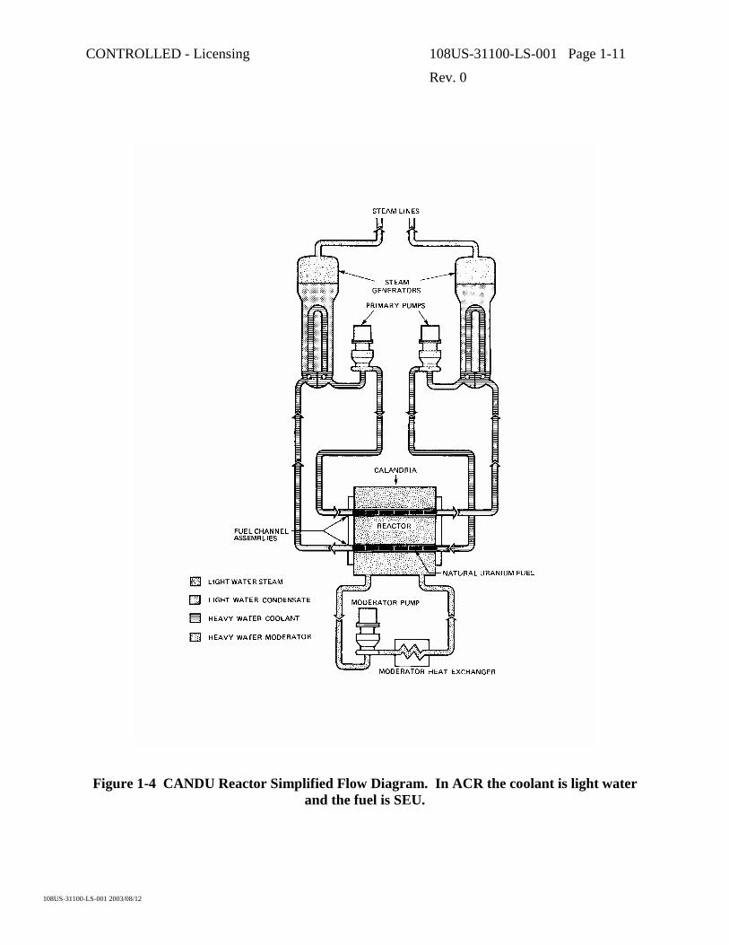
CONTROLLED - Licensing 108US-31100-LS-001 Page 1-11
Rev. 0
108US-31100-LS-001 2003/08/12
Figure 1-4 CANDU Reactor Simplified Flow Diagram. In ACR the coolant is light water and the fuel is SEU.

CONTROLLED - Licensing 108US-31100-LS-001 Page 1-12
Rev. 0
108US-31100-LS-001 2003/08/12
Figure 1-5 A CANDU Fuel Bundle
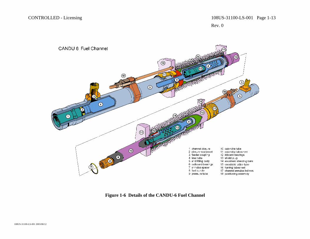
CONTROLLED - Licensing 108US-31100-LS-001 Page 1-13
Rev. 0
108US-31100-LS-001 2003/08/12
Figure 1-6 Details of the CANDU-6 Fuel Channel
CONTROLLED - Licensing 108US-31100-LS-001 Page 1-14
Rev. 0
108US-31100-LS-001 2003/08/12
Figure 1-7 The ACR Fuel Channel

CONTROLLED - Licensing 108US-31100-LS-001 Page 2-1
Rev. 0
108US-31100-LS-001 2003/08/12
2. FUEL CHANNEL DESIGN REQUIREMENTS
2.1 Introduction
CANDU fuel channels have generally been designed to provide an operating life of 30 years, at 80 to 90% capacity, during which time they must satisfy various functional, performance, safety, material, reliability, maintainability, inspection, testing, etc. requirements. This section briefly summarizes these requirements.
2.2 Functional Requirements
The functional requirements for the current generation of CANDU fuel channels are to:
a) Support and appropriately locate uranium fuel in the reactor core to maximize the heat generated by nuclear fission of this fuel, including having one end of each fuel channel attached to a reactor end shield.
b) Be connected to the Heat Transport System and provide the pressure boundary for the reactor’s coolant while it flows around/through the fuel bundles so the heat generated by nuclear fission is efficiently transferred to the coolant.
c) Allow fuelling machines to remove irradiated fuel and insert new fuel while the reactor is operating at full power.
d) Permit the gas of the Annulus Gas System to flow through a sealed fuel channel annulus so any leakage of the reactor’s coolant from a pressure tube can be quickly detected (leak-before-break).
2.3 Performance Requirements
The performance requirements are primarily the quantitative design requirements or design allowances corresponding to the above functional requirements. These performance requirements are generally imposed onto the fuel channel by its interfacing systems, e.g., the fuel channel Class 1 pressure boundary components experience the Heat Transport System operating conditions since they provide part of the pressure boundary for the reactor’s coolant. The performance requirements for the current generation of CANDU fuel channels are summarized in the following.
2.3.1 Requirements from Reactor Physics
Because a CANDU reactor generates heat by the nuclear fission of uranium, the fuel channels must incorporate radiation shielding where they pass through the reactor end shields, so that maintenance and inspection can be carried out in low radiation fields during reactor shutdowns. The target shielding requirement for the current generation of CANDU reactors is a maximum dose rate at the feeder cabinet face of 1.0 mSv/h, 24 hours after shutdown of the reactor. (To help achieve this, a shield plug is locked inside each end fitting to add additional material to attenuate radiation where the channels pass through the reactor end shields.)

CONTROLLED - Licensing 108US-31100-LS-001 Page 2-2
Rev. 0
108US-31100-LS-001 2003/08/12
Because the current generation of CANDU reactors use natural uranium fuel, it is required that the neutron absorption for in-core materials be as low as possible, thus heavy water is used for both the coolant and the moderator. Also, zirconium materials are used to fabricate almost all in-core structures and it is ensured that the volume of this material is no more than required to satisfy their design code. In addition, the required corrosion/wear allowances for in-core structures are minimized by using optimum chemistries for the reactor’s coolant and the gas in the fuel channel annulus, by minimizing the pressure tube wear from fuel fretting/sliding, by minimizing the pressure and calandria tube wear from the spacers in the annulus between these tubes, etc. In ACR, the use of SEU fuel allows both light water coolant and thicker components that can provide advantages such as reduced in-reactor deformation.
Reactor physics considerations also define the basic geometry of the CANDU reactor and its horizontal fuel channels, e.g., the lattice pitch (horizontal and vertical distance between the axes of adjacent fuel channels) for the current generation of CANDU reactors is 285.75 mm (11.25 inch) and the internal diameter of the pressure tubes is about 103 mm (4 inch). The diameter of the calandria tube that surrounds each pressure tube in the current generation of CANDU reactors is about 129 mm (5 inch). For ACR the lattice pitch is 220 mm and the calandria tube outside diameter is 156 mm.
2.3.2 Requirements from the Heat Transport System
The fuel channel Class 1 pressure boundary components, and the fuel channel internal components, must be designed to withstand the flow, temperature, pressure and transient service conditions (warmup, startup, cooldown, shutdown, reactor stepback, reactor trip, turbine trip, etc.) of the reactor’s coolant, including the loads that act on the fuel channel during these conditions. This includes ensuring (in collaboration with fuel designers) that there is a low pressure drop associated with the coolant flowing through the channel and that this coolant flow produces only minimal vibration of the fuel, which minimizes pressure tube wear from fuel fretting. For the current generation of CANDU reactors, the peak flow, temperature and pressure of the coolant are about 28 kg/s, 313ºC and 11 MPa, respectively.
Heat loss from the hot coolant to the relatively cool moderator and end shield cooling water must be minimized. To achieve this, there is an annular gap between the outside of a pressure tube and the inside of the calandria tube surrounding it, as well as between the outside of an end fitting and the inside of the lattice tube surrounding it, to provide a thermal barrier during reactor operating conditions. (This annular gap is maintained by having spacers between the pressure and calandria tube of each fuel channel and having sleeve bearings between each end fitting and the lattice tube which supports it.)
2.3.3 Requirements from Fuel Handling
Allowing fuelling machines to remove used fuel and insert new fuel while the reactor is operating includes permitting fuel bundles to pass freely through the reactor core during refueling. Thus the fuel channels must provide a sufficiently large unobstructed diameter (at
CONTROLLED - Licensing 108US-31100-LS-001 Page 2-3
Rev. 0
108US-31100-LS-001 2003/08/12
least as large as the 103 mm (4 inch) inside diameter of as-fabricated pressure tubes) and not have any gaps/steps that might either inhibit fuel sliding or damage the fuel elements.
In order to cater for the required on-power fuel insertion and removal operations, various fuel channel details must be designed in close collaboration with the fuelling machine/hardware designers to ensure the fuel channel is compatible with the fuelling machine/hardware design. This primarily involves ensuring that the outboard end of each end fitting can be sealed by an appropriate removable channel closure (target leak rate of 0.42 g/h of coolant), as well as accommodate having a fuelling machine clamp onto it and make a high-pressure seal. It also must be possible for a fuelling machine to lock/unlock a removable shield plug that is at an appropriate location inside an end fitting. Thus the fuelling machine/hardware designers specify various detailed geometric, surface finish, etc. requirements for portions of the end fitting.
2.3.4 Requirements from the Annulus Gas System
To ensure that pressure tubes will exhibit a ‘leak-before-break’ behavior as defense-in-depth assurance that delayed hydride cracking (see Subsection 2.7.2.2) can not cause a loss of coolant accident, it is required that any water leaking into the annulus between a pressure tube and the calandria tube surrounding it must be quickly detected. Thus this annulus must be sealed (without producing a large resistance to pressure tube elongation) and allow the annulus gas to flow through it so this gas can be monitored1 for moisture.
Water leakage into the Annulus Gas System (AGS) through any mechanical joints in its boundary must be consistent with the background moisture limits for the AGS moisture detection system. Since both the pressure tube to end fitting and the calandria tube to reactor end shield rolled joints can leak heavy water into the AGS, they must be very leak-tight, as was discussed in Subsection 2.3.1. (End shield cooling water should not be able to leak into the AGS since the lattice tubes that pass through a reactor end shield are welded to it.)
Leakage of annulus gas from the mechanical joints of the AGS (like the shrink-fit between an end fitting and the ring to which the fuel channel annulus bellows is welded) is also required to be consistent with the ability to provide an appropriate ‘leak-before-break’ behavior for the pressure tubes.
2.4 Safety Requirements
The pressure boundary integrity of the fuel channel assembly must be maintained, and the flow of the reactor’s coolant must not be obstructed, not only during all reactor operating conditions but also during most postulated accident cases (the exceptions are addressed in the following paragraph). This ensures that the fuel in the core of a reactor will continue to be cooled and that 1 This monitoring must be able to detect the leakage from a pressure tube crack sufficiently
quickly so the reactor can be shutdown before the crack could reach an unstable length. It is required that an analysis involving the Annulus Gas System leak detection capability and the reactor shutdown procedure be performed to demonstrate an appropriate ‘leak-before-break’ behaviour is achieved, as discussed in Section 12 of this report.

CONTROLLED - Licensing 108US-31100-LS-001 Page 2-4
Rev. 0
108US-31100-LS-001 2003/08/12
the functions of the safety systems will not be impaired. The length of the fuel bundle cavity shall be greater than the largest predicted fuel string length to accommodate the maximum fuel string expansion that can occur during a postulated loss of coolant accident with the emergency core cooling system unavailable. In addition, the largest possible gap between fuel and a shield plug shall not result in loss of either fuel channel integrity or bundle geometry in a postulated reverse flow condition. As well, under certain postulated accident conditions, the fuel channel design for the current generation of CANDU reactors must allow the pressure tube to balloon/sag into contact with the calandria tube surrounding it to provide sufficient heat transfer from the fuel channel to the moderator so pressure tube rupture is avoided. In ACR, such an occurrence is only expected with a severe accident. The pressure boundary integrity of a fuel channel can be lost only during a postulated:
• Spontaneous pressure tube rupture,
• Severe flow blockage in a single fuel channel and
• Single inlet feeder break resulting in flow stagnation.
During these single-channel events, the ability to shut down the reactor must not be impaired and all other fuel channels, feeders, etc., must remain intact, even if the Emergency Core Cooling System were unavailable.
2.5 Seismic Requirements
The fuel channel assembly must be designed to satisfy the Design Basis Earthquake (DBE) as an emergency (ASME Code level C) loading condition, as specified in the CAN3-N289 series of Canadian Standards. This ensures that fuel channels retain their pressure boundary integrity and allow the reactor’s coolant to continue to flow through them during/after a DBE. A dynamic analysis is performed for the whole reactor assembly, including its fuel channels, to determine the seismic loading on the fuel channels. The magnitude of these loads, including the possibility that one or two fuelling machines may be attached to a fuel channel, and the number of seismic cycles is then provided as input to the fuel channel stress analysis.
During a seismic event, the resulting interaction loads between a fuelling machine and channel may result in a temporarily increased leakage. This temporarily increased leakage must not exceed the capability for coolant make-up.
2.6 Codes and Standards
The design, analysis and testing of the fuel channel Class 1 pressure boundary components must satisfy the requirements of Canadian Standard CAN/CSA-N285.0, which extensively references the ASME Code, but also specifies additional requirements and materials, as discussed in Section 4 of this report.
The fuel channel components must be manufactured to the CSA-Z299 Quality Assurance Standards or the equivalent ISO-9000 requirements.

CONTROLLED - Licensing 108US-31100-LS-001 Page 2-5
Rev. 0
108US-31100-LS-001 2003/08/12
2.7 Materials Requirements
The materials from which the fuel channel components that are part of the AGS (like the fuel channel annulus bellows) are fabricated must exhibit acceptable corrosion behavior in the presence of the annulus gas. This gas nominally is dry CO2 with a small amount of oxygen, but may contain various amounts of moisture.
The materials from which the fuel channel Class 1 pressure boundary components, and their internal components, are fabricated must exhibit acceptable corrosion behavior in the presence of the reactor’s coolant. The pressure tubes must also have good resistance to sliding/fretting wear from the fuel and have adequate transparency to neutrons.
The material specifications for all fuel channel components that are fabricated using material whose specifications are not included in the ASME Code are given in Canadian Standard CAN/CSA-N285.6. This defines their requirements for impurities, heat treatment, cleanliness, testing and mechanical properties as a function of temperature.
2.7.1 Corrosion and Wear Allowances
Allowances for corrosion and wear (due to fuel sliding/vibration, relative axial movement between pressure and calandria tubes, etc.) must be established for the fuel channel components and must be taken into account when calculating dimensions for stress analysis of these components.
2.7.2 Allowance for the Effect of Environment on Material Properties
The effects of any significant environmental factors (stress, temperature, irradiation, hydrogen/deuterium absorption, etc.) on fuel channel material properties must be addressed during fuel channel design/analysis. It must be demonstrated that no reduction in the stress margins governing new construction will occur in-service and that protection against non-ductile failure is provided in accordance with the ASME Code, Section III, paragraph NB-3211(d). Two unique aspects of the in-service behavior of pressure tubes that must be accommodated are summarized in the following subsections.
2.7.2.1 Creep and Growth Deformation
The combination of stress, temperature and fast neutron flux results in a significant irradiation-induced creep and growth of the pressure tube. The fuel channel must be designed to accommodate the maximum pressure tube elongation, wall thickness reduction, diameter increase and sag predicted to occur during its design life. This includes providing adequate bearing lengths, allowing for the feeder/feeder spacing needed to accommodate the maximum anticipated differential elongation of pressure tubes, ensuring that the fuel channel annulus provides adequate space for the maximum anticipated expansion of the pressure tube diameter, ensuring that during reactor operating conditions a pressure tube can not sag into contact with the calandria tube surrounding it and ensuring that calandria tubes do not sag into contact with the

CONTROLLED - Licensing 108US-31100-LS-001 Page 2-6
Rev. 0
108US-31100-LS-001 2003/08/12
reactivity control units located below some of the calandria tubes. (The creep and growth deformation of pressure tubes is discussed further in Section 8 of this report.)
2.7.2.2 Delayed Hydride Cracking
Under certain conditions of temperature, stress and hydrogen/deuterium concentration, pressure tubes may be susceptible to crack initiation and growth by the Delayed Hydride Cracking (DHC) mechanism. The fuel channel must be designed to ensure there is a very low probability that DHC might occur in any pressure tube.
To minimize the probability that DHC might occur in any pressure tube, both their hydrogen/deuterium concentration and peak tensile stress are minimized. For example, the initial hydrogen concentration of as-fabricated pressure tubes is less than 5 ppm for the most recently fabricated tubes. Also, the coolant and AGS chemistries are closely controlled to minimize the ingress of hydrogen/deuterium into pressure tubes. In addition, ‘zero-clearance’ pressure tube to end fitting rolled joints are used in reactor construction to minimize the residual tensile stresses in pressure tubes (to less than 130 MPa). The probability/size of pressure tube flaws that may be generated during tube manufacturing, fuel channel fabrication and reactor operation is also minimized. The design of the fuel channel annulus spacer, and the axial separation between these spacers, ensures that a hot pressure tube will not sag into contact with the cooler calandria tube surrounding it and thus avoids the possibility of having a significant thermal gradient in a pressure tube which may lead to hydride accumulation at the cooled portion of the tube and the potential for unstable cracking. (The possibility that pressure tubes might exhibit DHC, and how it is avoided, is discussed further in Section 12 of this report.)
In addition, as was mentioned in Subsection 2.3.4, it is required that pressure tubes exhibit a ‘leak-before-break’ behavior as a defense-in-depth protection that DHC will not result in an unstable rupture. This is discussed further in Section 12 of this report.
2.8 Reliability and Maintainability Requirements
Due to the high radiation fields associated with operating fuel channels, their components must be designed, fabricated and installed to achieve the maximum degree of reliability that is practical with minimal inspection and maintenance throughout their design life, which has generally been 30 years at 80 to 90% capacity. In addition, the inspection and maintenance that is required must be able to be completed as quickly as possible to minimize radiation exposure to personnel, as well as minimizing outage durations and costs.
The only planned maintenance for fuel channels during their design life is one mid-life adjustment (changing the reactor end shield to which fuel channels are attached) so pressure tube elongation can be accommodated by bearings at both ends of the fuel channels. In addition, fuel channels have been designed such that, should a fuelling machine break-down while attached to a fuel channel, the fuel within that channel can be removed relatively easily from its other end.
To allow CANDU reactors to operate longer than the fuel channel life, the channels have been designed so they can be replaced relatively easily. This ensures that both the outage duration
CONTROLLED - Licensing 108US-31100-LS-001 Page 2-7
Rev. 0
108US-31100-LS-001 2003/08/12
required for channel replacement and the radiation exposure to personnel during channel replacement are minimized. The replaceability aspects of the fuel channel are discussed in more detail in Section 14 of this report.
2.9 Inspection and Testing Requirements
In addition to development/qualification testing for prototype fuel channel components, the following tests and inspections must be performed during/after the fabrication of production components and reactor construction.
2.9.1 Testing
The fuel channel Class 1 pressure boundary components are hydrostatically tested during fabrication. They also experience the in-situ hydrostatic pressure test that is performed for the Heat Transport System.
All rolled joints are dimensionally inspected and helium leak tested.
The fuel channel components that are part of the AGS experience the in-situ leak test that is performed for the AGS.
2.9.2 Inspection
As required by Canadian Standard CAN/CSA-N285.4 on the Periodic Inspection of CANDU Nuclear Power Plant Components, in-service inspection is performed for some fuel channels, as is discussed in Section 11 of this report.
2.10 Decontamination and Decommissioning Requirements
Fuel channel pressure boundary materials are selected to minimize the formation of long-lived radioactive nuclides. The fuel channel design avoids regions of stagnant flow where deposits can accumulate and crevices/pockets that will not drain.
Fuel channel Class 1 pressure boundary components are decontaminated as part of the Heat Transport System to achieve sufficiently low levels of radiation in the inlet and outlet reactor vaults so that maintenance can be carried out with minimal radiation exposure to personnel. The decontamination chemicals must be compatible with the channel components.
2.11 Interfacing Systems Requirements
The key fuel channel interfaces are:
a) Heat Transport System
b) Fuel
c) Fuel Handling System

CONTROLLED - Licensing 108US-31100-LS-001 Page 2-8
Rev. 0
108US-31100-LS-001 2003/08/12
d) Moderator System
e) Reactor Structure (Calandria and End Shield Assembly)
f) Reactivity Control Units
g) Annulus Gas System
This subsection defines the key requirements that the fuel channel imposes on these interfacing systems.
2.11.1 Heat Transport System
The reactor’s coolant must remove the heat generated in the fuel that resides in the fuel channels. Thus each fuel channel is connected to the Heat Transport System (HTS) by having an inlet and outlet feeder pipe attached to the inlet and outlet end fittings, respectively, near their outboard ends. The HTS, including its feeders and their supports, must be designed to minimize the loads applied to the fuel channels. In addition, adequate feeder/feeder spacing must be provided to accommodate the maximum anticipated differential elongation of pressure tubes.
The HTS must be very carefully controlled during construction, commissioning and operation to minimize the possibility that it might contain debris that could generate flaws in pressure tubes.
The HTS water chemistry must be maintained so corrosion of, and hydrogen/deuterium ingress into, the pressure tubes are minimized.
Overpressure protection for the fuel channel coolant pressure boundary components is provided by the HTS.
2.11.2 Fuel
The fuel must be designed to minimize the wear (sliding, fretting, etc.) of fuel channel components. This includes ensuring (in collaboration with the fuel channel designers) that the coolant flowing through the channel produces only minimal vibration of the fuel. The pressure drop associated with this flow must also be as low as practical.
2.11.3 Fuel Handling System
The fuelling machine must always be capable of aligning with each fuel channel, latching onto it and forming a leak-tight extension to the coolant pressure boundary without imposing excessive loads on the fuel channel. It shall also be capable of removing/replacing both a channel closure and shield plug from/into an end fitting, as well as removing used fuel and inserting new fuel.
2.11.4 Moderator System
The moderator system must efficiently remove the heat transmitted to the moderator by the fuel channels under all normal and accident conditions.

CONTROLLED - Licensing 108US-31100-LS-001 Page 2-9
Rev. 0
108US-31100-LS-001 2003/08/12
2.11.5 Reactor Structure
The deadweight load of the channels and their contents is supported by the reactor end shields. These end shields also appropriately locate the channels in the reactor core. The axial positioning of each fuel channel is obtained by an attachment to one end shield. This allows essentially unrestricted differential thermal axial expansion between each high temperature pressure tube and the lower temperature calandria tube surrounding it, as well as pressure tube elongation due to creep and growth.
2.11.6 Reactivity Control Units
The horizontal reactivity control units (flux detectors and poison injection nozzles) must not be located so close to the calandria tubes above them that these tubes may sag into contact with the reactivity control units.
2.11.7 Annulus Gas System
The AGS must provide insulation between the reactor’s hot coolant and the cooler moderator and end shield coolant. It must also provide an oxidizing atmosphere that inhibits hydrogen/deuterium ingress to a pressure tube from its annulus by maintaining an oxide on the pressure tube outside surface. In addition, the AGS must be capable of quickly detecting leakage from a pressure tube (leak-before-break) and also be capable of identifying the leaking channel from other channels and other potential sources of leakage (by remote means) so that this channel can be isolated for inspection and replacement.
The material from which the components that form the AGS boundary are fabricated must exhibit acceptable corrosion behavior in the presence of the annulus gas with various amounts of moisture.
Overpressure protection for the fuel channel annulus bellows is provided by the AGS.

CONTROLLED - Licensing 108US-31100-LS-001 Page 3-1
Rev. 0
108US-31100-LS-001 2003/08/12
3. FUEL CHANNEL DESIGN DESCRIPTION
3.1 Introduction
The fuel channel is one of the major distinguishing features of a CANDU reactor. Figure 3-1 is a schematic illustration showing the main components for one of the few hundred horizontal channels in each CANDU reactor core. The key components of the fuel channel are:
• the pressure tube,
• the end fittings that are attached to each end of the pressure tube,
• the calandria tube surrounding the pressure tube and
• the spacers in the annulus between the pressure and calandria tubes.
The following briefly describes each of these key fuel channel components.
3.2 Fuel Channel Components
3.2.1 Pressure Tubes
The pressure tubes pass through the reactor core with fuel bundles residing inside them and the reactor’s hot pressurized coolant flowing through them. In the current generation of CANDU reactors, this coolant has a peak temperature of about 313°C (at the outlet) and pressure of about 11 MPa (at the inlet). For ACR, the coolant has a peak temperature of about 325°C (at the outlet) and maximum pressure of about 13 MPa. These tubes experience corrosion from the coolant, a high neutron flux and also wear from fuel bundle vibration during reactor operation and movement during fuelling. They have sufficient strength to accommodate stresses and limit deformation from the loads, temperature and neutron flux that they experience during their design life.
A pressure tube acts as a horizontal beam supported at each end by its attachment to an end fitting and at intermediate points by the surrounding calandria tube, via ‘garter spring’ spacers located in the annulus between the two tubes.
The pressure tubes in the current generation of CANDU reactors are approximately 6 m long zirconium alloy cylinders having a 103 mm (4 inch) inside diameter and a 4.2 mm wall thickness. For ACR, this thickness has been increased to 6.5 mm, allowing the pressure tube to withstand higher temperatures and pressures. Thus their design consists primarily of determination of their length, inside diameter and wall thickness. The length of the pressure tubes is primarily determined from the length of the reactor core, which is obtained from reactor physics considerations. The inside diameter of the pressure tubes is derived from fuel passage and thermohydraulic considerations. The minimum allowable wall thickness of the pressure tubes is determined by stress analysis of these tubes as pressure-retaining components. This analysis complies with the Class 1 vessel design-by-analysis rules of Section III of the ASME Boiler and Pressure Vessel Code. The large diameter to wall thickness ratio for the pressure

CONTROLLED - Licensing 108US-31100-LS-001 Page 3-2
Rev. 0
108US-31100-LS-001 2003/08/12
tubes has allowed this evaluation to be performed using standard classical elasticity equations for thin-walled cylinders. (A finite element stress analysis is performed for the rolled joint that connects each end of a pressure tube to an end fitting.)
One of the requirements of the pressure tube design for the existing CANDU reactors has been to optimize the wall thickness to minimize the neutron absorption penalty. Since pressure and temperature vary along the length of a pressure tube when a reactor is operating, as is illustrated in Figure 3-2, the pressure tube design condition has been established by evaluating stresses at 20 locations along the length of the tube to determine the design location, which is the location requiring the largest wall thickness. For a typical channel, which has a few percent quality in the coolant at its outlet end, this location is about midway between the centre of the tube and its outlet end.
An allowance for corrosion and wear is added to the calculated minimum allowable wall thickness to establish the minimum wall thickness for pressure tube fabrication.
In design calculations, the design pressure has been determined by the set-point of the Heat Transport System relief valves. The design temperature has been that of a central fuel channel running at 110% of nominal fuel channel power due to recent refueling, plus an additional margin of about 10% for potential instrument error.
Since zirconium alloys are not included in the ASME Boiler and Pressure Vessel Code as an allowable Class 1 material, the pressure tube allowable design stress has been established using the results from an extensive test program performed by AECL and is specified in Canadian Standard CAN/CSA-N285.6, as discussed in a subsequent section of this report. The allowable design stress has been determined on the same basis as is done for ASME Class 1 materials, i.e., it is the lowest of either one-third of the minimum tensile strength or two-thirds of the minimum yield strength, both taken at the design temperature. For cold-worked zirconium-2.5% niobium, one-third of the minimum tensile strength is the governing condition. On this basis, the design stress of the pressure tube is 160 MPa (23,000 psi) at 300°C.
The pressure tube stresses are evaluated for both beginning-of-life and end-of-design-life conditions to account for pressure tube dimensional changes that occur over the life of the fuel channel. For the end-of-design-life condition, the upper-bound effects of thermal expansion and creep deformation, plus irradiation-induced creep and growth deformation, are considered and credit has been taken for part of the strength increase caused by irradiation. To ensure that pressure tube elongation, diameter increase, wall thickness reduction and sag are appropriately accommodated, the permanent deformation that occurs due to creep and growth during reactor operation is calculated from a deformation equation developed by AECL based on measurements of tube deformations in operating reactors and results from extensive research reactor testing, as described in Section 8 of this report.

CONTROLLED - Licensing 108US-31100-LS-001 Page 3-3
Rev. 0
108US-31100-LS-001 2003/08/12
3.2.2 Pressure Tube to End Fitting Rolled Joint
Each end of a pressure tube is roll-expanded into the bore at the inboard end of a stainless steel fitting. This cold-working of a portion of a pressure tube into a thick hub produces compressive residual stresses for sealing.
The pressure tube to end fitting rolled joint configuration is very simple, involving only three circumferential grooves in the end fitting hub, as illustrated in Figure 3-3. The rolled joint is made by inserting one end of a pressure tube into the hub at the inboard end of an end fitting after it has been heated, which on cooling develops a ‘zero-clearance’ fit. (The diametral fit at room temperature is 0.002” clearance to 0.007” interference.) The pressure tube is then rolled into this hub with a nominal 13.5% reduction in wall thickness, which causes pressure tube material to be extruded into the grooves in the end fitting hub to produce a very strong and leak-tight joint. The pressure tube to end fitting rolled joints in a CANDU reactor have never come apart nor allowed excessive leakage of the reactor’s coolant.
Although no rules are given in the ASME Code for the use of roll-expanded joints in Class 1 vessels, rules have been developed to ensure that a high-integrity joint satisfying the intent of the ASME Code is obtained. These rules are specified in Canadian Standard CAN/CSA-N285.2, as discussed in Section 4 of this report. This use of rolled joints has been developed, optimized and qualified by extensive full-scale testing and analysis of many hundreds of prototype rolled joints to demonstrate their acceptability for use in the fuel channels of a CANDU reactor, as described in Section 7 of this report. The rolled joint for ACR is being similarly proven in a rolled joint development program.
A finite element stress analysis of the rolled joint is conducted to confirm that the stresses in the rolled joint region meet the allowable limits specified in Canadian Standard CAN/CSA-N285.6. In addition, the three primary performance requirements for a pressure tube to end fitting rolled joint are:
• Low tensile residual stress in the pressure tube,
• High joint axial strength and
• Low joint leakage.
Residual stresses in the rolled portion of a pressure tube are compressive, which are not a concern. However, pressure tube to end fitting joints whose assembly clearance is near the high end of the allowable range can cause tensile residual stresses to exist slightly inboard of the rolled portion of the pressure tube. Canadian Standard CAN/CSA-N285.2 limits the peak value for these tensile stresses to avoid the initiation of delayed hydride cracking in pressure tubes. This requirement has been easily satisfied by the rolled joint design used in the construction of the current generation of CANDU reactors. (As residual stresses relax during reactor operation, the highest tensile residual stress values exist just after a rolled joint has been produced.)
The axial strength of a rolled joint design is measured in pull-out testing during which an axial load pulls a pressure tube out of its end fitting hub. Canadian Standard CAN/CSA-N285.2 specifies the minimum allowable value for the pull-out load, which has been easily satisfied by

CONTROLLED - Licensing 108US-31100-LS-001 Page 3-4
Rev. 0
108US-31100-LS-001 2003/08/12
the rolled joint design used during the construction of the current generation of CANDU reactors as this joint has an axial strength that is almost as high as that for a pressure tube. Since this strength is primarily due to the pressure tube material that is extruded into the end fitting grooves, it is not affected by the stress relaxation that occurs during reactor operation. In fact, testing has shown that the pull-out strength for pressure tube to end fitting rolled joints increases with reactor operation, due to material irradiation strengthening.
Pressure tube to end fitting rolled joints need to be very water leak-tight. To ensure this, each joint produced during reactor construction has its leak-tightness checked with a highly sensitive helium leak test. Further assurance that appropriate joints are produced in reactor construction has been obtained by performing a thorough dimensional inspection of each joint.
The excellent performance of the pressure tube to end fitting rolled joints in the current generation of CANDU reactors verifies that these joints operate very reliably.
3.2.3 End Fittings1
A stainless steel fitting is attached to each end of a pressure tube as an out-of-core extension of the pressure tube by rolling an end of a pressure tube into the bore at the inboard end of the fitting. Each of these end fittings has a side-port near its outboard end for connection of a feeder pipe, which provides a flow path for the reactor’s coolant between the pressure tube and the rest of the Heat Transport System. In the current generation of CANDU reactors, feeders are attached to end fittings by bolted connections involving a metallic seal ring.
The outboard end of each end fitting is sealed by a removable channel closure and accommodates having a fuelling machine clamp onto it and make a high-pressure seal to allow on-power refueling. Allowing periodic access for the fuelling machines to remove irradiated fuel from each channel and insert new fuel into it, while the reactor is operating, is a significant characteristic of CANDU reactors.
As is illustrated in Figure 3-1, each fuel channel end fitting passes through one of the reactor end shields. The contacting surfaces of the end fitting and the end shield lattice tube, which supports it, are sleeve bearings that allow axial sliding of the end fittings.
A ring is shrunk onto each end fitting so one end of a bellows, which is discussed in Subsection 3.2.6, can be welded to it.
1 Two somewhat different end fitting design concepts are used in the existing CANDU
commercial power reactors to accommodate two different fuelling concepts. The reactors at the Bruce and Darlington sites have relatively large diameter end fittings because of the use of a fuel carrier for fuelling operations. All other CANDU reactors have a smaller diameter end fitting, with fuel sliding through the end fitting’s liner tube during refuelling. Most other aspects of the two end fitting designs are identical. In ACR, due to the smaller lattice pitch, the end fitting diameter is reduced to accommodate the feeders. The liner tube is also shorter, being located only in the region of the feeder joint.

CONTROLLED - Licensing 108US-31100-LS-001 Page 3-5
Rev. 0
108US-31100-LS-001 2003/08/12
End fittings are designed as Class 1 vessels with a finite element stress analysis being performed to show they satisfy the stress limits in Canadian Standard CAN/CSA-N285.6 (see Section 4).
The end fittings are made from a modified2 AISI type 403 stainless steel. They are forged in one piece, heat treated and then machined to their finished size. The side-port for connection of a feeder pipe is machined from a thickened region on one side of the end fitting.
Additional information about end fitting properties and performance is described in Section 15 of this report.
3.2.4 Calandria Tubes
Each pressure tube is located inside a calandria tube with the gas-filled annulus between these two tubes insulating the high temperature/pressure coolant inside the pressure tube from the lower temperature/pressure moderator located outside the calandria tubes. These calandria tubes span the calandria vessel between its two end shields. These tubes, which are arranged in a square pitch to form a circular lattice array, provide access through the calandria for the fuel channel assemblies. Each calandria tube helps to support the pressure tube contained in it by means of four spacers in the annulus between the pressure and calandria tube. (These spacers are discussed in the Subsection 3.2.5.)
The calandria tubes act as axial stays that help the calandria vessel resist the internal pressure of the moderator. In all CANDU reactors constructed to date, each end of a calandria tube is rolled under a stainless steel insert into a circumferential groove in a hub in one of the end shields of the reactor, forming a high-integrity ‘sandwich’ joint (see Figure 3-4). For ACR, no insert is required as the calandria tube is thicker at the ends and can be rolled directly into the tubesheet.
The calandria tubes in all existing CANDU commercial power reactors were manufactured by brake-forming a rolled strip of Zircaloy-2 material into a cylindrical shape whose internal diameter is about 129 mm (5 inch), welding the axial seam, then annealing the tube. This material was chosen for its low neutron absorption and corrosion resistance. These tubes are expanded (flared) at each end so the sandwich rolled joint used to join each end of the tube to an end shield does not reduce the unobstructed bore of the calandria tube.
3.2.5 Annulus Spacers
Four annulus spacers keep each pressure tube separated from the calandria tube that surrounds it. These spacers allow the calandria tube to provide sag support for the pressure tube while also allowing essentially unrestrained differential axial movement between the two tubes. The spacers are positioned about a meter apart in the fuel channel annulus so that pressure tube sag between spacers will not result in a pressure tube contacting the calandria tube surrounding it during the fuel channel design life.
2 As specified in Canadian Standard CAN/CSA-N285.6, which is discussed in Section 4 of
this report.

CONTROLLED - Licensing 108US-31100-LS-001 Page 3-6
Rev. 0
108US-31100-LS-001 2003/08/12
The annulus spacers are coiled springs whose ends are hooked together to form a ring that is a snug fit on a pressure tube. These ‘garter springs’, which have been qualified for this application by an extensive test program, roll to accommodate the relative axial movement between a pressure and calandria tube with minimal wear. (These spacers are discussed further in Section 17 of this report.) The ACR, design uses a tight-fitting garter spring, similar to the recent CANDU 6 designs, with a larger coil diameter due to the larger annulus. It features a welded coil (for structural integrity) around a welded girdle wire (to allow detection).
3.2.6 Bellows
Three-ply bellows fabricated from Inconel 600 material are connected between each end fitting and a lattice site of an end shield by shrink-fitting then welding one end to the end shield and welding the other end to a ring that is a shrink-fit on the end fitting. These bellows seal the fuel channel annulus while providing minimal resistance to pressure tube elongation. The annular space around the fuel channel, which is filled with dry CO2 gas, is connected to an Annulus Gas System that incorporates moisture-detecting instrumentation to warn of leaks from any of the Heat Transport System, the moderator or the end shield cooling water.
3.3 Analyses
In addition to addressing the effects of the temperature and pressure of the reactor’s coolant, the calculation of stresses and assessment of the fatigue life for fuel channel components includes:
- Weight of fuel channel components, fuel and coolant
- Feeder pipe loads and torques
- Fuelling machine loads
- Axial loads due to the bellows that seal the fuel channel annulus, fuel movement and end fitting bearing friction
- Effects of initial tube bows, misalignment and end-of-design-life sag
- Loads imposed during a seismic event
Pressure tube deformations due to creep and growth are calculated using formulae developed by AECL based on measurements of tube deformations in operating reactors and results from extensive research reactor testing, as described in Section 8 of this report.
Calculation of the increase of pressure tube diameter is used to establish the:
- Allowable diameter of the fuel channel annulus spacer (‘garter spring’)
- Coolant flow conditions at end-of-design-life
Calculation of the elongation of the pressure tube is used to establish the:
- Bearing lengths
- Bellows extension

CONTROLLED - Licensing 108US-31100-LS-001 Page 3-7
Rev. 0
108US-31100-LS-001 2003/08/12
- Feeders and feeder connection stresses
Calculation of channel sag is used to establish the:
- Number and spacing of the ‘garter spring’ annulus spacers
- Annulus spacer loads
- Clearance for fuel passage inside the pressure tubes
- Clearance between fuel channels and the reactivity control units that are located below some fuel channels
Assessments are made of various component clearances and how they are affected by:
- Temperature and pressure
- Manufacturing tolerances
- Installation tolerances
- Hydrostatic loads
- Creep and growth deformation
- Differential deformation
3.4 Operating Conditions for the Fuel Channels in the Existing CANDU Commercial Power Reactors and Changes for ACR
The operating conditions for the fuel channels in the existing CANDU commercial power reactors and the changes for ACR are summarized in the following subsections.
3.4.1 Pressure Distribution
As shown schematically in Figure 3-2, the typical pressure distribution along the length of a CANDU fuel channel has a nearly linear decrease from inlet to outlet. The peak pressure (at the inlet end) in the most recently constructed reactors is about 11 MPa. For ACR the peak pressure is increased to about 13 MPa to allow for higher temperature coolant.
3.4.2 Temperature Distribution
The typical temperature distribution along the length of a pressure tube is also shown schematically in Figure 3-2. Little temperature change occurs within about 0.5 m from the inlet end and within about 1.5 m from the outlet end, where the coolant is boiling. Within the wall of the pressure tube only a small temperature gradient exists, with the outside surface being about 3°C hotter than the inside due to gamma heating. The peak temperature (near the outlet end) is ∼ 313°C in the most recently constructed reactors. In ACR, this peak temperature is increased to about 327°C.

CONTROLLED - Licensing 108US-31100-LS-001 Page 3-8
Rev. 0
108US-31100-LS-001 2003/08/12
3.4.3 Flux Profile
The maximum fast flux occurs at the centre of a pressure tube and decreases to about zero at its ends. The maximum flux in the most recently constructed reactors is about 3.7 x 10¹⁷ n/(m2⋅s) (E>1 MeV). The flux profile is more uniform along the length of the pressure tube for the ACR with the maximum being slightly higher at about 4.0 x 10¹⁷ n/(m2⋅s)(E>1 MeV).
3.4.4 Heat Transport Fluid
Limited boiling occurs near the outlet ends of the channels for all but the earliest reactors, with the highest quality being about 6%. Evaluation of the effects of boiling in the laboratory and from surveillance tube examinations has not shown any harmful effects. The maximum heat transport mass flow in the most recently constructed reactors is about 28 kg/s.
3.4.5 Coolant Chemistry
The heat transport coolant is kept at a pH of 10.2 to 10.8 with lithium additions and the hydrogen overpressure is controlled within the range 3 to 10 cm3/kg (mostly kept in the range 3 to 5 cm3/kg). The oxygen concentration remains below 10 ppb (generally less than 5 ppb) to limit corrosion.
3.4.6 Cooldown Rate
Because the pressure tubes are relatively thin-walled, they can be cooled rapidly from operating conditions to room temperature. The maximum allowable reactor shutdown rate is set by other components in the Heat Transport System.
3.5 Design Documentation
The fuel channel documentation that must be prepared includes:
- System Classification List (SCL)
- Design Requirements (DR)
- Design Description (DD)
- Design Manual (DM)
- Design Specification (DS) for the pressure boundary components
- Stress Report (SR) for pressure boundary components
- Design Drawings

CONTROLLED - Licensing 108US-31100-LS-001 Page 3-9
Rev. 0
108US-31100-LS-001 2003/08/12
Figure 3-1 Schematic of a Fuel Channel in a CANDU Reactor
Figure 3-2 Pressure and Temperature Variation Trends along the Length of a Fuel Channel and their Influence on the Required Wall Thickness

CONTROLLED - Licensing 108US-31100-LS-001 Page 3-10
Rev. 0
108US-31100-LS-001 2003/08/12
Figure 3-3 Typical Pressure Tube to End Fitting Rolled Joint
Figure 3-4 Schematic of an Installed Calandria Tube for Current Reactors

CONTROLLED - Licensing 108US-31100-LS-001 Page 4-1
Rev. 0
108US-31100-LS-001 2003/08/12
4. CODES AND STANDARDS FOR THE DESIGN AND FABRICATION OF FUEL CHANNELS
4.1 Introduction
The American Society of Mechanical Engineers (ASME), with the support of regulatory bodies, has developed a Boiler and Pressure Vessel Code containing requirements that have resulted in the economical design and fabrication of safe boilers and pressure vessels. The Canadian nuclear industry recognizes this Code as the reference authority defining technical standards that will be applied to the pressure boundary components of CANDU nuclear power plants. Thus, CANDU pressure boundary components must comply with the ASME Code, Section III (Rules for Construction of Nuclear Power Plant Components), technical requirements. However, as the ASME Code primarily addresses PWR and BWR pressure vessel reactors, it does not adequately address some of the unique features of pressure tube reactors with on-power refueling. Therefore, some additional technical requirements/rules are needed to ensure that the unique features of CANDU pressure boundary components are consistent with the intent of the ASME Code.
Efforts were made to expand the ASME Code to cover the unique CANDU features through applications for Code Cases and through having Canadian members on various ASME Code committees. However, as progress by this route was very slow and extremely limited, an initiative was started by the Canadian Nuclear Association (CNA), later taken over by the Canadian Standards Association (CSA), to produce a series of Canadian Standards which would provide appropriate requirements/rules for the unique features of a CANDU pressure tube reactor with on-power refueling. This work produced the CAN/CSA-N285 series of Canadian National Standards. The documents in this series that apply to the fuel channel assemblies, which are part of the CANDU Class 1 Heat Transport System, are:
N285.0 General Requirements for Pressure-Retaining Systems and Components in CANDU Nuclear Power Plants
N285.2 Requirements for Class 1C, 2C and 3C Pressure-Retaining Components and Supports in CANDU Nuclear Power Plants
N285.4 Periodic Inspection of CANDU Nuclear Power Plant Components N285.6 Material Standards for Reactor Components for CANDU Nuclear Power
Plants N285.8 (draft)
Technical Requirements for In-Service Evaluation of Zirconium Alloy Pressure Tubes in CANDU Reactors
A primary role for the N285.0 Standard is to modify some of the general requirements specified in the ASME Code, Section III, in order to comply with the Canadian jurisdictional and administrative systems for classification, registration, quality assurance, etc. It also indicates when the other Standards in the N285 series, which specify technical requirements/rules complementing those of the ASME Code, apply.

CONTROLLED - Licensing 108US-31100-LS-001 Page 4-2
Rev. 0
108US-31100-LS-001 2003/08/12
The N285.2 Standard specifies that the ASME Code, Section III, technical requirements/rules for the design and fabrication of pressure boundary components must be satisfied and, in addition, that for some CANDU components additional requirements/rules addressing the unique features of a pressure tube reactor with on-power refueling must also be satisfied. For example, the ASME Code does not provide rules for fabricating rolled joints. Such joints have been developed for joining CANDU in-core pressure boundary components fabricated from zirconium alloys to out-of-core steel components with appropriate requirements/rules for them being specified in N285.2.
The N285.4 Standard specifies the rules for periodic inspections that assess the integrity of pressure boundary components for CANDU reactors to ensure the probability of their failure remains low. These inspection rules are somewhat different than those in the ASME Code, Section XI, since CANDU reactors do not have a single large pressurized reactor vessel, but instead have a large number of much smaller pressurized components. This topic is discussed further in Section 11 of this report.
The N285.6 Standard specifies materials that can be used in addition to those allowed by the ASME Code. For example, it specifies requirements for the manufacture, inspection, properties, etc., of various zirconium alloys that have been developed to provide the unique properties needed by many of the in-core components of CANDU pressure tube reactors. Detailed fabrication/inspection specifications and detailed design data are provided which are comparable with the type of material information given in the ASME Code, Section II. (ASTM-B353 now also specifies similar manufacturing and properties requirements for zirconium alloy pressure tubes.)
The draft for the N285.8 Standard specifies the assessment procedures, material property data and acceptance criteria for any flaws requiring disposition1 that may be observed during inspections of in-service pressure tubes. As this draft has not yet been fully endorsed for formal issue, details of its contents are not discussed in this report.
The following outlines the contents of the N285.0, N285.2 and N285.6 Standards, with emphasis on the portions of these documents that apply to the design and material selection for CANDU fuel channel Class 1 pressure boundary components.
4.2 CAN/CSA-N285.0, General Requirements
The topics covered in the CAN/CSA-N285.0 Standard are:
1. Scope
2. Reference Publications and Definitions
3. General Requirements
1 Assessment to determine if a pressure tube can remain in-service when a flaw indication
observed during periodic inspection is equal to or greater than the indication from the periodic inspection calibration specimen.

CONTROLLED - Licensing 108US-31100-LS-001 Page 4-3
Rev. 0
108US-31100-LS-001 2003/08/12
4. Responsibilities
5. Classification
6. Registration
7. Design
8. Materials
9. Fabrication and Installation
10. Quality Assurance
11. Inspection, Examination and Testing
12. Records, Identification and Reports
13. In-Service Requirements
14. Supports
Many of the sections in this Standard specify requirements that ensure compliance with the Canadian jurisdictional and administrative systems, e.g., the types of documentation required, who must produce them, when they must be produced, etc. Other sections define where the appropriate technical requirements/rules for CANDU pressure boundary components are specified. For example, Section 7 on ‘design’ states that “Class 1 systems and components shall be designed to comply with the requirements of Section III, Division 1, NB-3000.” In addition, it also states that “components classified as Class 1C, 2C, 3C shall be designed to comply with the requirements of CSA Standard CAN/CSA-N285.2.” Thus a Class 1C2 component, like a pressure tube, must satisfy all ASME-NB-3000 requirements and also the additional requirements given in CAN/CSA-N285.2.
Section 8 on ‘materials’ states that “material for pressure-retention in Class 1 systems and components shall comply with the requirements of Section III, Division 1, NB-2000 or CSA Standard CAN/CSA-N285.6.” The N285.6 Standard specifies the requirements for materials that have been developed to provide the unique properties needed by many of the in-core CANDU components.
4.3 CAN/CSA-N285.2, Requirements for Class 1C, 2C and 3C Pressure-Retaining Components
In addition to satisfying the ASME Code design-by-analysis rules for a pressure vessel, some CANDU pressure boundary components must also satisfy rules specified in the CAN/CSA-N285.2 Standard. The topics covered in this Standard are:
1. Scope
2. Definitions, Reference Publications and Abbreviations 2 The term Class 1C designates a Class 1 component for which additional requirements are
specified in CAN/CSA-N285.2.

CONTROLLED - Licensing 108US-31100-LS-001 Page 4-4
Rev. 0
108US-31100-LS-001 2003/08/12
3. General Requirements
4. Specific Requirements
5. Fuel Channel Assemblies
6. Calandria Assembly
7. Reactivity Control Units
8. Joints Between Tubular Components
9. Fuel-Handling Equipment
The design rules, in addition to those of the ASME Code, that are specified for Class 1C fuel channel components are addressed in Section 5 of N285.2, which references its Section 8 that specifies generic requirements for mechanical joints. The topics covered in Section 5 are:
1. General
2. Pressure tube to end fitting joints
3. Pressure tubes
4. Channel closure
The additional design rules specified for the three unique CANDU fuel channel components addressed in N285.2 to complement the ASME Code rules are summarized in the following.
4.3.1 Pressure Tube to End Fitting Joints
Zirconium alloys cannot be welded satisfactorily to steels due to the formation of brittle intermetallic compounds. Proprietary mechanical joint designs have therefore been developed for joining in-core zirconium components to out-of-core steel components. All of these joints between zirconium alloy tubes and steel hubs involve roll-expansion to produce residual compressive stress for sealing. In addition, the tube material is extruded into one or more circumferential grooves in the hub to provide a large pull-out strength. For the pressure tube to end fitting rolled joint, the tube material is extruded into 3 grooves in the bore at the inboard end of an end fitting to provide a pull-out strength that is approximately equal to the axial strength of the pressure tube. (The development programs from which the pressure tube to end fitting joint design used in the existing CANDU commercial power reactors evolved, and the test results which demonstrate the integrity of these rolled joint designs, are described in Section 7 of this report.)
In addition to satisfying the ASME Code Class 1 vessel design-by-analysis rules, the pressure tube to end fitting rolled joint must also satisfy the rules specified in N285.2, which include:
• “joints shall be designed in accordance with the rules of Section 3, paragraph NB3200 (design by analysis) of the ASME Boiler and Pressure Vessel Code”.
• “prototype joints shall be subjected to performance tests to determine the structural integrity of the joints under simulated service conditions”.
CONTROLLED - Licensing 108US-31100-LS-001 Page 4-5
Rev. 0
108US-31100-LS-001 2003/08/12
• “pullout load shall exceed three times the design condition axial load, including pressure, when the test is performed at design temperature, or four times if the test is at ambient conditions”.
• all production rolled joints must be inspected to confirm that the key “parameters determined from the prototypes (e.g., the reduction in wall thickness required to produce joints of adequate strength) have been achieved”.3
• “production joints shall be produced using the same tooling design and procedures that have been qualified in the manufacture of prototype joints”. (Several sets of the same design of tooling have been used.)
4.3.2 Pressure Tubes
In addition to satisfying the Class 1 vessel design-by-analysis rules of the ASME Code, Section III, Subsection NB3200, pressure tubes must also satisfy the requirements given in N285.2, which include:
• “The design and stress analyses shall include the effects of creep (and growth) deformation.” The horizontal pressure tubes increase in length and diameter, their wall thickness decreases and they also sag from the weight of the fuel and coolant contained in them. This deformation occurs primarily as a result of irradiation-induced creep and growth, which is a permanent pressure tube deformation due to the combined effects of temperature, stress and neutron irradiation. (Pressure tube creep and growth deformation is discussed in Section 8 of this report.) Several design considerations are affected by pressure tube creep and growth deformation and appropriate geometric limits have been specified as design limits.
• “The minimum wall thickness assumed in the analyses shall include allowances for internal and external corrosion, thinning (due to pressure tube creep and growth deformation) and wear from fuel movement.” Stress analysis has been performed for the beginning-of-life condition when the as-fabricated wall thickness and unirradiated material properties apply. Analyses have also been performed for the end-of-design-life condition when pressure tube diameter and length have increased, wall thickness has decreased, material strength has increased and the fuel channel has its maximum sag.
• “Pressure tubes made from zirconium alloys shall be protected against delayed hydride cracking by ensuring that the maximum tensile stress, under design level A (normal) and level B (upset) conditions, plus the maximum initial residual tensile stress, shall at no time exceed 67% of the tensile stress required to initiate delayed hydride cracking as determined in the laboratory by tests on unnotched specimens.” (Delayed hydride cracking is discussed in Section 12 of this report.)
• “Pressure tubes shall be supported such that they will not contact the calandria tube during the life of the channel.” Contact between a hot pressure tube and the cooler calandria tube
3 In addition, during reactor construction each pressure tube to end fitting joint has also
been tested for helium leakage.

CONTROLLED - Licensing 108US-31100-LS-001 Page 4-6
Rev. 0
108US-31100-LS-001 2003/08/12
surrounding it is not allowed because such contact can produce thermal gradients which may lead to hydride accumulation at the cooled portion of the pressure tube and the potential for unstable cracking.
• “Pressure tube material shall be capable of sustaining a subcritical through-wall crack (i.e., leak before breaking).”
• “A system capable of detecting leaks before through-wall cracks grow to unstable lengths shall be provided.” A very sensitive leak detection capability exists for CANDU pressure tubes so there is a high confidence they will leak before breaking, i.e., a controlled reactor shutdown will occur before a leaking pressure tube might rupture. (This is discussed further in Section 12 of this report.)
4.3.3 Channel Closure
During reactor operation, the outboard end of each end fitting is normally closed and sealed by a mechanical closure plug. To allow the on-power refueling of a channel, the fuelling machine is connected, and sealed, to an end fitting before this closure plug is removed. In addition to satisfying the ASME Code Class 1 design rules, this removable pressure boundary component must also satisfy the rules specified in N285.2, which include:
• “The closure body shall close off the end-fitting bore so that any failure of the seal disc does not result in a loss of coolant in excess of the capacity of the make-up system.”
• “Channel closures shall be tested for leakage each time they are installed and prior to removal of the fuelling machine.”
• Channel closures “shall be locked in place by closure safety locks”.
4.4 CAN/CSA-N285.6, Material Standards for Reactor Components
The CAN/CSA-N285.6 Standard specifies materials that have been developed to provide the unique properties required in a pressure tube reactor, which includes using zirconium alloys for most of the in-core components. For example, it specifies requirements for the manufacture, inspection, properties, etc., of a cold-worked Zr-2.5% Nb alloy (R60901) that has been developed as a practical pressure tube material for CANDU reactors. Since this material is not presently listed in the ASME Code, Section III, as an allowable material for Class 1 application, its requirements are specified in the N285.6 Standard. (ASTM-B353 has recently also incorporated similar fabrication and properties requirements for zirconium alloy pressure tubes.)
The topics covered in the N285.6 Standard, which provides manufacturing, inspection and properties requirements for materials that can be used in addition to those allowed by the ASME Code, are:
1. Pressure tubes
2. Reactivity control rods
3. Liquid injection shutdown system nozzles

CONTROLLED - Licensing 108US-31100-LS-001 Page 4-7
Rev. 0
108US-31100-LS-001 2003/08/12
4. Calandria tubes
5. Wire for fuel channel spacers
6. Inspection criteria for zirconium alloys
7. Zirconium alloy design data
8. Fuel channel end fittings
9. Supports
Pressure tubes (N285.6.1) and end fittings (N285.6.8) are the two Class 1 fuel channel pressure boundary components for which materials are specified that currently are not ASME allowable materials. The two sections of N285.6 that address these two components are briefly discussed in the following.
4.4.1 N285.6.1, Seamless Zirconium Alloy Tubing for Fuel Channels (Pressure Tubes)
This section of N285.6 specifies manufacturing and properties requirements for seamless zirconium alloy pressure tubes. The topics covered in it are:
1. Scope
2. Definitions
3. Ingot requirements
4. Billet requirements
5. Extrusion requirements
6. Tube requirements
7. Tube material requirements
8. Inspections, tests and examination
9. Quality control records
10. Packaging and shipment
N285.6.1 references both N285.6.6 (Inspection Criteria for Zirconium Alloys) and N285.6.7 (Zirconium Alloy Design Data) for inspection requirements and design data, respectively. For the inspection and non-destructive examination of zirconium alloy components, the requirements of the ASME Code, Section V, are supplemented by additional requirements specified in N285.6.6. The design data for pressure tubes, which are specified as a function of temperature in N285.6.7, are derived the same way as ASME design data (e.g., the peak allowable design stress is the lowest of two-thirds the minimum yield stress or one-third the minimum tensile strength, both taken at the design temperature). These data are described in Section 5 of this report.

CONTROLLED - Licensing 108US-31100-LS-001 Page 4-8
Rev. 0
108US-31100-LS-001 2003/08/12
4.4.2 N285.6.8, Material Requirements for End Fittings
End fittings need very good corrosion resistance at their seal faces. In addition, a high end fitting strength is needed in the region of the rolled joint with the pressure tube to withstand the rolling forces and maintain the compressive residual stress needed to retain leak-tightness. The necessary corrosion, strength and toughness requirements are met by a modified type 403 martensitic stainless steel. The necessary modifications, which are restrictions in the chemical composition limits, include restricting the range of the main alloying elements (such as carbon and chromium) to reduce variability in tensile and impact properties. In addition, the allowable limits of residual elements (such as phosphorus, sulphur and copper) are reduced to improve corrosion resistance and to reduce the shift in the room temperature NDT with irradiation. Cobalt is also restricted for activity transport reasons. All of the requirements for this material, including its inspection criteria and design data, are specified in N285.6.8. Further discussion about end fitting properties and performance is provided in Section 15 of this report.
4.4.3 N285.6.4, Thin Walled, Large Diameter Zirconium Alloy Tubing (Calandria Tubes)
The calandria tubes4, which are part of the Class 3 moderator pressure boundary, are another important part of the CANDU fuel channel. For all existing CANDU reactors, these tubes have been made by brake-forming a rolled strip of Zircaloy-2 material into a cylindrical shape, welding the axial seam, then annealing the tube. As occurs for all of the zirconium alloys covered in N285.6, the inspection requirements and design data for calandria tubes are given in N285.6.6 and N285.6.7, respectively.
4.5 Summary
The CAN/CSA-N285 series of Canadian National Standards provide requirements/rules to ensure that the unique features of a CANDU pressure tube reactor with on-power refueling are consistent with the intent of the ASME Code. They provide general requirements which comply with the Canadian jurisdictional and administrative systems, design requirements/rules that must be used in addition to those of ASME for the unique components in a CANDU pressure tube reactor and manufacturing/properties requirements for materials that have been developed to provide the unique properties needed by many of the in-core components of these reactors.
4 The design pressure for calandria tubes has been 10 to 12 psig (69 to 83 kPa(g)) with a
design temperature of 100°C and a normal operating temperature of less than 85°C. Further discussion about calandria tubes is provided in Section 16 of this report.

CONTROLLED - Licensing 108US-31100-LS-001 Page 5-1
Rev. 0
108US-31100-LS-001 2003/08/12
5. MATERIALS FOR THE FUEL CHANNEL ASSEMBLIES
5.1 Introduction
This section of the report contains a summary of the properties of the materials used for the components in the Fuel Channel Assemblies. The recommended property values, for physical and mechanical properties, to be used for design and calculations are shown in table form.
The components included in this section are:
a) pressure tubes - cold worked Zr-2.5Nb
b) calandria tubes - annealed Ziracloy-2 or annealed Zircaloy-4
c) spacers - heat treated Inconel X-750 coil with Zircaloy-2 girdle wire
d) end fittings - heat treated AISI Type 403 martensitic stainless steel
In the following subsections the material microstructures, and the mechanical and physical properties for the fuel channel components are described, and the recommended values are shown in tables.
The mechanical properties of interest are:
i) Design Stress Intensity Values,
ii) 0.2% yield strength (YS) and,
iii) ultimate tensile strength (UTS).
The physical properties of interest are:
i) Young’s modulus,
ii) Shear modulus,
iii) Poisson’s ratio,
iv) thermal conductivity, and
v) thermal expansion coefficient.
5.2 Material Microstructures
The microstructures of the fuel channel components have been examined by the optical and electron microscopy of polished and etched samples. In addition, x-ray techniques have been used to characterize the textures. The microstructural features found in the components are listed below.

CONTROLLED - Licensing 108US-31100-LS-001 Page 5-2
Rev. 0
108US-31100-LS-001 2003/08/12
5.2.1 Pressure Tubes
Pressure tubes have a two-phase microstructure consisting of elongated platelets of hexagonal close packed alpha-zirconium surrounded by a thin, grain-boundary network of partially-decomposed, body-centered cubic, beta-zirconium containing about 20% Nb. The alpha platelet dimensions are typically about 20 µm long in the axial direction of the tube x 5 µm wide (circumferential direction) x 0.5 µm thick (radial direction). The beta phase is about 0.05 µm thick. As a result of the extrusion process the tubes develop a significant crystallographic texture that results in anisotropic material properties. The hexagonal axes of the alpha grains are preferentially oriented near the radial-circumferential plane of the tube, with a predominance in the circumferential (transverse) direction and with very few in the axial direction (See Subsection 10.2).
The dislocation density in the tubes, measured by x-ray line broadening techniques, is about 5x10¹⁴m-2.
The microstructure of the Zr-2.5Nb pressure tubes also contains zirconium hydrides. These are platelets with typical dimensions 0.05 mm diameter x 0.001 mm thick. Their actual dimensions are affected by hydrogen concentration in the material and cooling rate, being larger for slower cooling rates. Hydrides generally lie with the platelet normals close to the radial direction of the tube.
5.2.2 Calandria Tubes
Calandria tubes are fabricated by the seam welding of annealed Zircaloy-2 or Zircaloy-4 strip. Although tubes made to date have all been Zircaloy-2, Zircaloy-4 is equally acceptable. The expected performance of Zircaloy-4 for calandria tube conditions is considered to be indistinguishable from that of Zircaloy-2. It is anticipated that in future CANDU reactors seamless calandria tubes may be used. The strip has an equiaxed microstructure with the alpha grains having a diameter about 0.01 mm. The material contains the usual Fe/Cr/Ni/Zr inter-metallic particles found in the Zircaloy alloys; there are also a few hydrides but their presence has had no effect on the behavior of the material.
The axial weld in the calandria tube is made using filler wire and is proud on the surface in the as-welded condition. The subsequent cold rolling and the annealing operations in the manufacturing sequence for the calandria tube lead to the recrystallization of the weld material and the formation of smaller alpha grains from the original as-welded large grains. The centre of the weld has an equiaxed alpha grain size about 0.02 mm, with slightly larger grains in the heat affected zone.
The crystallographic texture of the calandria tube is dominated by the texture of the cold rolled and annealed strip with a preferred orientation of the hexagonal axes of the grains towards the radial direction of the finished tube
The dislocation density of the annealed material is lower than that in pressure tubes - it has been measured using x-ray line broadening techniques to be about 3-6 x 10¹³/m2.

CONTROLLED - Licensing 108US-31100-LS-001 Page 5-3
Rev. 0
108US-31100-LS-001 2003/08/12
5.2.3 Spacers
Two materials are used for current fuel channel spacers:
i) heat treated Inconel X-750 coil, and
ii) cold-drawn Zircaloy girdle wire.
The microstructure of the Inconel X-750 consists of equiaxed grains.
5.2.4 End Fittings
The end fittings are made from quenched and tempered AISI Type 403 stainless steel. The microstructure consists of tempered martensite, but some delta ferrite may also be present.
5.3 Mechanical Properties
5.3.1 Design Stress Intensity and Mechanical Properties
The Design Stress Intensity values for the pressure tube, calandria tube, spacer coil and the end fitting materials are shown in Table 5-1(a) [5.1,5.2]. The variation of UTS and YS versus temperature for the AISI Type 403 end fitting material is shown in Table 5-1(b).
5.4 Physical Properties
5.4.1 Elastic Modulus, Shear Modulus and Poisson’s Ratio
The elastic moduli data for the pressure tube, calandria tube, spacer coil and end fitting materials material are shown in Table 5-2 [5.1,5.2]. The elastic moduli for zirconium alloys are listed for both the longitudinal and transverse directions to account for the anisotropy.
5.4.2 Thermal Conductivity
The thermal conductivity data for the pressure tube, calandria tube, spacer coil and end fitting materials are shown in Table 5-3 [5.1, 5.2, 5.3]. The thermal conductivity data for zirconium alloys are listed for the radial, axial and circumferential directions relative to the component axis or the principal working direction. This is due to the fact that zirconium alloys also show anisotropic behavior with respect to their thermal conductivity properties.
5.4.3 Thermal Expansion
The thermal expansion data for the pressure tube, calandria tube, spacer coil material are shown in Table 5-4(a) [5.1, 5.3]. The thermal conductivity data for zirconium alloys are listed for the radial, axial and circumferential directions relative to the component axis or the principal working direction to account for anisotropy. The variation of thermal coefficient of expansion versus temperature for AISI Type 403 end fitting material is shown in Table 5-4(b)[5.2].

CONTROLLED - Licensing 108US-31100-LS-001 Page 5-4
Rev. 0
108US-31100-LS-001 2003/08/12
5.5 References
[5.1] CAN/CSA-N285.6.7 Zirconium Alloy Design Data
[5.2] CAN/CSA-N285.6.8 Martensitic Stainless Steel for Fuel-Channel End Fittings
[5.3] ASME Boiler and Pressure Vessel Code, Section II, Part D Properties.

CONTROLLED - Licensing 108US-31100-LS-001 Page 5-5
Rev. 0
108US-31100-LS-001 2003/08/12
Table 5-1(a) Design Stress Values for Pressure Tube, Calandria Tube, Spacer and End Fitting Materials
Min. Min. Allowable stress (MPa) for metal temperature (°C) Alloy and Product Condition YS,
MPa UTS, MPa
20 50 100 150 200 250 300 350 400 500
R60901 Zr-Nb
Pressure Tubes 1,2
Extruded, cold worked (20-30)%
+ 400°C/24h stress relief
330 (300°C)
480 (300°C)
236.8 226.4 207.9 191.4 172.9 167.9 160.0 150.9 134.8 77.4
R60802 R60804
Calandria Tubes 3
Annealed 300 (20°C) 320(T) 320(L)
415 (20°C) 415(T) 425(L)
138.3
138.3
129.2
129.2
114.1
114.1
97.5
97.5
83.7
83.7
72.0
72.0
63.0
63.0
56.6
56.6
52.7
52.7
45.8
45.8
N07750 Inconel X-750
Spacer Coil
No. 1 Temper, Aged 730°C
16 hours
1095 (20°C)
1391 (20°C)
438.7 435.6 430.4 425.0 419.8 414.8 409.6 404.1 398.9 388.7
Type 403 End Fitting
Quenched and Tempered
585 (20°C)
725 (20°C)
241 241 241 236 232 229 225 221 217 209
1. The CAN/CSA Standard N285.6.1 has three types of cold-worked Zr-2.5Nb alloy. The allowable stress intensities shown here correspond to the current pressure tube used in CANDU-6.
2. The specified mechanical properties for pressure tube material are measured at 300°C. For other zirconium alloy components the specified mechanical properties are measured at room temperature (20°C).
3. The design stress intensity and mechanical properties for calandria tube material are listed for the longitudinal(L) and transverse(T) directions to the principal working direction. This is due to the fact that zirconium alloys show anisotropic behavior with respect to their mechanical properties.

CONTROLLED - Licensing 108US-31100-LS-001 Page 5-6
Rev. 0
108US-31100-LS-001 2003/08/12
Table 5-1(b) Ultimate Tensile Strength (UTS) and Yield Strength (YS) Values for End Fitting Material
UTS and YS values (MPa) for metal temperature (°C) Property 20 50 100 150 200 250 300 350 400 500
UTS 725 725 725 708 697 686 674 662 650 626 YS 585 583 555 538 524 510 498 486 474 450

CONTROLLED - Licensing 108US-31100-LS-001 Page 5-7
Rev. 0
108US-31100-LS-001 2003/08/12
Table 5-2 Elastic Moduli Values for Pressure Tube, Calandria Tube, Spacer and End Fitting Materials
Alloy and Product
Condition Property Direction Temperature (°C)
20 50 100 150 200 250 300 400 500 R60901 Zr-Nb Pressure Tubes
Extruded cold-worked (20-30%) + 400°C/24 h stress relief
Young’s modulus (GPa) Shear modulus (GPa) Poisson’s ratio
Long. Trans. Long. Trans Long. Trans
94.6101.9
34.535.1
0.3890.457
92.5100.4
33.834.5
0.3890.463
88.9 98.0 32.6 33.5
0.387 0.472
85.495.631.432.5
0.3840.481
81.893.130.331.5
0.3790.489
78.3 90.7 29.1 30.5
0.371 0.498
74.7 88.3 27.9 29.5
0.361 0.507
67.6 83.4 25.6 27.5
0.340 0.525
60.5 78.6 23.2 25.6
0.310 0.542
R60802 R60804 Calandria Tubes
Annealed Young’s modulus (GPa) Shear modulus (GPa) Poisson’s ratio
Long. Trans. Long. Trans Long. Trans.
94.095.834.535.7
0.3750.345
92.193.633.735.1
0.3750.345
89.0 90.6 32.6 33.8
0.375 0.345
86.087.831.432.8
0.3750.347
82.884.830.231.5
0.3770.350
79.6 81.9 29.0 30.4
0.380 0.355
76.5 79.0 27.8 29.2
0.380 0.360
70.1 73.1 25.5 26.8
0.385 0.362
63.8 67.1 23.1 24.5
0.390 0.367
N07750 Inconel X-750 Inconel Spacer Coil*
No. 1 Temper Aged 730°C 16 hours
Young’s modulus (GPa) Shear modulus (GPa) Poisson’s ratio
Long. Long. Long.
213.6
78.9
0.294
212.2
78.4
0.295
209.5
77.3
0.296
206.7
76.3
0.297
203.9
75.3
0.299
201.2
74.3
0.300
198.4
73.3
0.301
192.2
71.0
0.304
186.0
68.7
0.306 Type 403 End Fitting
Quenched and Tempered
Young’s modulus (GPa)
- 201 200 198 195 192 189 181 173 157
* Inconel X-750 data based on INCO technical documentation, and Aerospace Structural Metals Handbook, Volume 4, Alloy Inconel X-750, Code 4105.

CONTROLLED - Licensing 108US-31100-LS-001 Page 5-8
Rev. 0
108US-31100-LS-001 2003/08/12
Table 5-3 Thermal Conductivity Data for Pressure Tube, Calandria Tube, Spacer and End Fitting Materials
Thermal Conductivity Coefficient, W/(m.K), for metal temp, °C Alloy and Product Condition Tube
Direction 20 50 100 150 200 250 300 350 400 500 R60901 Zr-Nb Pressure Tubes
Extruded, cold worked (20-30)% + 400°C/24h stress relief
Radial circumf. axial
17.0 17.4 17.7
17.0 17.3 17.6
17.2 17.1 17.5
17.2 17.2 17.7
17.6 17.6 18.1
17.8 17.9 18.5
18.2 18.3 18.8
18.5 18.7 19.2
18.9 19.0 19.5
19.6 19.7 20.3
R60802 R60804 Calandria Tubes
Annealed Radial circumf. axial
12.7 13.6 12.9
12.9 14.1 13.3
13.2 14.8 14.0
13.6 15.6 14.7
13.9 16.3 15.4
14.4 17.1 16.1
14.8 17.8 16.8
15.3 18.5 17.6
15.8 19.3 18.3
17.0 20.8 20.6
N07750 Inconel X-750 Inconel Spacer Coil
No. 1 Temper Aged 730°C 16 hours
- 11.9 12.3 12.9 13.5 14.1 14.8 15.5 16.2 16.9 18.3
Type 403 End Fitting
Quenched and Tempered
- 25.32 25.51 25.80 26.10 26.41 26.73 27.05 27.37 27.69 28.33

CONTROLLED - Licensing 108US-31100-LS-001 Page 5-9
Rev. 0
108US-31100-LS-001 2003/08/12
Table 5-4(a) Thermal Expansion Data for Pressure Tube, Calandria Tube, and Spacer Materials
Coefficient of Thermal Expansion (x 10-6/°C) Alloy and Product
Condition Tube Direction 0-300°C 400°C 450°C 500°C Equation describing expansion
R60901 Zr-Nb Pressure Tubes
Extruded, cold-worked (20-30%) + 400°C/24 h stress relief
Long.
Trans.
5.1
6.9
3.26
6.9
2.89
6.9
2.14
7.6
∆L/L = -0.38 x 10⁻⁴ + 5.86 x 10⁻⁶ ∆T + 3.72 x 10⁻⁹ ∆T2
∆L/L = 6.9 x 10⁻⁶ ∆T
R60802 R60804 Calandria Tubes
Annealed Long.
Trans.
5.3
6.8
5.3
6.8
5.3
6.8
5.3
6.8
∆L/L = 5.3 x 10⁻⁶ ∆T
∆L/L = 6.8 x 10⁻⁶ ∆T N07750 Inconel X-750 Inconel Spacer Coil
No. 1 Temper Aged 730°C 16 hours
- 7.5 7.6 7.9 8.4 −

CONTROLLED - Licensing 108US-31100-LS-001 Page 5-10
Rev. 0
108US-31100-LS-001 2003/08/12
Table 5-4(b) Thermal Expansion Data for End Fitting Material
Temperature (°C) Mean Coefficient of Thermal Expansion in Going from
21°C to Indicated Temperature (10-6 per °C) 50 10.8 100 11.1 150 11.3 200 11.5 250 11.6 300 11.7 350 11.8 400 11.9 500 12.1
CONTROLLED - Licensing 108US-31100-LS-001 Page 6-1
Rev. 0
108US-31100-LS-001 2003/08/12
6. MANUFACTURE OF PRESSURE TUBES
6.1 Background
The manufacture of pressure tubes for CANDU reactors commenced over 40 years ago. To date, more than 17,000 tubes have been produced and installed in reactor units located within Canada and overseas. The initial product of the CANDU pressure tube-manufacturing program was a seamless Zircaloy-2 tube; however, in the early 1960s, an alternate alloy with improved performance characteristics (Zr-2.5Nb) was introduced. The Zr-2.5Nb alloy represents the current production standard and approximately 95% of all CANDU pressure tubes have been manufactured from this basic material.
The pressure tube is designed to have a uniform wall and a uniform inside diameter. A typical as-manufactured length is about 6.5m, with an inside diameter of 103 mm and a wall thickness of 4.2 mm, although for the ACR reactor the wall thickness is increased to about 6.5 mm. The pressure tubes are seamless and all have been fabricated by processes that include hot extrusion and cold reduction. As the properties of the pressure tube have a complex relationship to the in-service performance, both the final product specifications and the fabrication processes are closely controlled. Changes to the manufacturing specifications and processes, resulting from continued fuel channel design and development or manufacturing process improvements, are subject to qualification programs. Typically, these qualification programs involve the combined efforts of researchers, pressure tube designers and the component manufacturers.
The specialized manufacturing requirements have resulted in a small number of manufacturers being involved and remaining in the field since the initial production. With the exception of the recent production for the Qinshan reactors, for which the Chepetski Mechanical Plant in Russia made the Zr-2.5Nb ingots and billets, most ingot and billet production has originated at Wah Chang in Albany, Oregon, USA. Extrusion and cold reduction have been completed at Nu-Tech Precision Metals Inc. (formerly Chase Nuclear) in Arnprior, Ontario. Bristol Aerospace Limited had been responsible for the finishing operations on Zr-2.5Nb pressure tubes until about 1989 when this function was taken over by Nu-Tech Precision Metals. The overall pressure tube procurement practice is controlled by three main requirements: the design requirements, the metallurgical and fabrication process requirements, and the quality assurance requirements. These three aspects are described in detail in Subsections 6.3, 6.4, and 6.5 below.
6.2 Steps in Pressure Tube Fabrication
The main steps in the fabrication of Zr-2.5 Nb pressure tubes are described below and illustrated in Figure 6-1. For current pressure tube procurement, Nu-Tech Precision Metals Inc. is generally the single primary contractor. Nu-Tech could subcontract the ingot and billet production to one of the following qualified suppliers:
• Wah Chang, Albany, Oregon, USA
• Chepetski Mechanical Plant in Glazov, Russia,

CONTROLLED - Licensing 108US-31100-LS-001 Page 6-2
Rev. 0
108US-31100-LS-001 2003/08/12
• Cezus in France (qualified to produce Zr-2.5Nb billets, but not yet used for production).
The remaining stages of manufacture (extrusion, cold drawing and finishing) are carried out at Nu-Tech facilities.
6.2.1 Ingot
Depending on the source, Zr-2.5Nb ingots may be fabricated from zirconium sponge produced using the Kroll Process (Wah Chang and Cezus) or 55% zirconium powder, produced using an electrolytic process, together with 45% crystal bar (Chepetski). The sponge, or powder/crystal bar mix, is compacted into briquettes, which together with alloy additions are electron beam welded to form an electrode that is then melted in a consumable electrode vacuum arc furnace. The melting process, together with intermediate surface conditioning operations, may be repeated up to four times and results in a Zr-2.5Nb ingot with low inclusion and volatile impurity contents. The finished ingot is machined to remove surface imperfections and to allow the required volumetric ultrasonic inspection, the latter being used to establish the depth of any solidification piping cavities. Ingot production and forging practice are designed to maximize the product yield through the reduction of ingot piping effects. However, to ensure that all piping cavities, and any other material discontinuities, are removed, each ingot is cropped using the data from the ultrasonic inspection as a reference.
Chemical samples are obtained at several locations along the machined ingot length. The samples are evaluated for conformance to the specification requirements with respect to the two major alloying elements, niobium and oxygen, and 24 residual elements. However, some elements such as carbon and iron are now recognized as having an important role on in-reactor behavior and have target concentration ranges that have to be confirmed at the ingot stage. Thus, it is appropriate to consider these elements as alloys rather than residual elements. Chemical homogeneity in the Zr-2.5Nb ingot is the responsibility of the manufacturer and it is achieved by balancing the electrode composition against the known distribution behavior of the elements [6.1].
From the impurity elements, whose concentrations are controlled, hafnium is of interest due to its significant contribution towards the neutron absorption cross-section of the alloy and its concentration is limited to 0.028 at % (50 ppm(wt)).
Recent research has shown that the control of certain other elements is desirable to either enhance in-reactor operation or to improve the properties of the pressure tubes. Thus, the
• Iron concentrations are controlled, as continued research shows a correlation between iron contents and the creep/growth behavior and deuterium uptake during reactor operation
• Oxygen concentrations are controlled, as continued research shows a relationship between the oxygen concentration and the in-reactor creep/growth behavior
• Carbon concentrations are controlled as continued research shows a relationship between the carbon concentration and the fracture toughness and deuterium uptake during reactor operation

CONTROLLED - Licensing 108US-31100-LS-001 Page 6-3
Rev. 0
108US-31100-LS-001 2003/08/12
• Phosphorous concentrations are controlled as research shows a relationship between the phosphorous concentration and the fracture toughness
Hydrogen levels in the ingot are kept as low as possible (now < 5 ppm(wt)) because hydrogen concentration may be a life-limiting factor as additional ingress of hydrogen isotope (deuterium in heavy water coolant) into the tube material occurs during operation [6.1].
The hardness of the alloy is also verified at each sampling station of the ingot.
6.2.2 Billets
Depending on the source of the Zr-2.5Nb ingot, the ingot is converted into beta-quenched hollow billets ready for extrusion through one of two qualified processing routes.
At Wah Chang, the ingot is initially converted into small round sections called “logs” through a combination of press forging and rotary forging. For the former operation, the ingot is preheated to 1015°C and deformed into a polygon using a slow strain rate press forging practice designed to break down the as cast structure and produce a smaller more homogeneous microstructure. The polygon, after heating to 815°C, is converted into a round “log” using a high strain rate rotary hammer forge process that further breaks down the ingot microstucture by elongating the material and torsionally deforming the interior. The next step is to cut the log into billets with a length specifically designed to produce a finished pressure tube with minimal waste material. To optimize the yield and further minimize waste, a recent development has been the introduction and qualification of a press piercing process at <890°C to generate the hole in the centre of the billet. This process eliminates the wasteful trepanning process previously used.
At the Chepetski Mechanical Plant, the ingot is converted into logs by preheating to about 1050°C and helically rolled in two passes into a log. The helical rolling process uses barrel shaped rollers set at an angle to the machine centerline, similar to the Mannesman tube making process. This rolling process breaks down the ingot structure through a combination of compressive, torsional and elongation forces resulting in a reduction in diameter and elongation of the ingot. As with Wah Chang, the logs are sectioned into billets optimized to minimize waste during the remaining processing, but the hole in the centre is produced in the traditional way by drilling or trepanning.
For both suppliers, the microstructure of the hollow billets is homogenized and optimized by a solution heat treatment in the beta-phase region followed by water quenching (beta-quenching). Beta quenching of a hollow billet, as opposed to a solid billet, is another recent innovation to reduce variability in the final pressure tube microstructure through optimization of the extrusion feedstock. Each billet is examined with dye penetrant for surface discontinuities. The billets are also examined ultrasonically, using the immersion technique and a continuous overlapping scan, with two opposed angle beams in the circumferential direction and with straight (normal) beam in the radial direction. One billet per ingot is checked for conformance to the specified material composition requirements.

CONTROLLED - Licensing 108US-31100-LS-001 Page 6-4
Rev. 0
108US-31100-LS-001 2003/08/12
6.2.3 Extrusion Hollows
Billets, protected from oxidation at elevated temperatures by copper cladding, are preheated to 815°C in the alpha-beta phase field and then extruded into tube hollows. The extrusion process forms the elongated dual phase microstructure that is retained through to the final tube product. (The extruded product has some microstructual variability associated with the temperature changes occurring during extrusion. This results in small but noticeable differences in in-reactor performance between the front end (exits the extrusion press first) and the back end of the final tube.) The tube hollows are surface conditioned to remove the protective cladding and any surface oxide formed during the extrusion process.
6.2.4 Cold Drawn Tubes
Tube hollows undergo cleaning, sand blasting and a surface treatment that ensures the required lubricant adherence during drawing. The cold reduction to the final tube size is typically carried out in two passes, each producing a cross-sectional area reduction of 14 to 15%, for a total of 24 - 30%. The cold drawn tubes are sand blasted and cleaned. The tube finishing includes honing of the inside surface and grinding and polishing of the outside surface. Honing removes approximately 0.06 mm of material containing minor surface imperfections. The centerless grinding operation is combined with wall thickness measurements, and it is selective so that the largest amount of material is removed at the thickest wall regions (thus minimizing the amount of material installed in the reactor core), while maintaining the minimum required wall thickness along the length of the tube. As part of the manufacturers internal quality assurance, the honed and polished tube is ultrasonically examined using a normal beam pulse-echo inspection and a four-directional shear wave, with two waves traveling in opposite directions around the circumference and two additional shear waves traveling in the axial direction of the tube. Other tests carried out at this manufacturing step include a hydrostatic pressure test, chemical analysis of selected tube off-cuts to ensure conformance of the four major alloying and residual elements, a tensile test of a tube specimen at 300°C, a hardness check, and a corrosion test of a small section of tube to confirm that the required material corrosion properties are met.
6.2.5 Finished Tubes
The final stage of pressure tube production includes a stress relief operation, dimensional checks, and non-destructive examinations. Following cleaning, the tubes are stress relieved in a steam autoclave for 24 hours at 400°C. The pure steam atmosphere produces a uniform dark oxide layer, approximately 1 micron thick, which acts as a barrier to deuterium ingress, controls friction during installation and provides added wear resistance during operation. The stress relieved tubes are visually examined and checked for conformance to dimensional requirements on straightness, ovality, bore size, outside diameter and wall thickness; deviations from specifications are corrected as necessary. The tube end dimensions, in particular, are required to have closer tolerances than the body of the tube, since the wall thickness and outside diameter variations in these regions affect the quality of the pressure tube to end fitting rolled joints. The final ultrasonic inspection of full tube lengths includes a four-directional shear wave and two normal beam scans, one of which is in the high frequency range of 50-100 MHz. The high

CONTROLLED - Licensing 108US-31100-LS-001 Page 6-5
Rev. 0
108US-31100-LS-001 2003/08/12
frequency normal beam examination is a recent addition to the final tube inspection. It has been shown to be effective in detecting and characterizing low angle lap flaws, and thus it provides additional assurances against the occurrence of such flaws in the finished tube. The eddy current technique is employed in the examination of the inside and outside tube surface layers to provide additional sensitivity to near surface flaws and will detect metallurgically-bonded laminations. The finished tubes are weighed and packaged for shipment.
6.3 Design Responsibility
In pressure vessel manufacture, the manufacturer is normally responsible for the stress analysis of the component. The pressure tubes are considered an element of the total fuel channel design, the design of which is carried out by the designer (AECL) and not by the manufacturer. The interface is governed by minimum property requirements imposed on the manufacturer.
The design properties of cold worked Zr-2.5Nb alloy are covered by the Canadian Standards Association (CSA) specification N285.6.7. The basic requirements of the CSA Code correspond to the intent of the ASME Code Section III for Class 1 components. CSA N285.6.7 lists the derived allowable stress intensity values at design temperatures. In the fuel channel analysis, the design stress intensity allowables used are equal to one third of the specified minimum tensile strength at the design temperature, determined in a manner which is in agreement with ASME code practice.
The tensile properties measured in the tubes are arranged to provide additional margins over normal code limits. Thus the properties are measured in the longitudinal direction at the front end of the tube. The front end is weaker than the back end by a small amount and the longitudinal direction is also weaker than the hoop direction by about 12%. The properties of the tubes are generally well in excess of the specified minima and thus provide a suitable margin over the minimum design requirements.
6.4 Fabrication Process and Metallurgical Requirements
Most metallurgical requirements relate to controlling three main phenomena seen in operating tubes; namely deformation, corrosion and deuterium pick up and sensitivity to delayed hydride cracking, although recently in-reactor property variability has been added to the list.
For the metallurgical structure, the three main microstructure parameters that control the performance in-reactor from a creep and growth deformation aspect are:
• texture
• dislocation density
• grain size and shape
The most important step in producing the metallurgical structure and subsequent variability of the finished pressure tubes is the extrusion process [6.2]. The extrusion process effectively determines texture, grain shape and homogeneity in the finished tubes although the extrusion

CONTROLLED - Licensing 108US-31100-LS-001 Page 6-6
Rev. 0
108US-31100-LS-001 2003/08/12
feedstock plays a role by providing a homogeneous microstructure that is optimized by the beta quench.
The subsequent cold working increases the dislocation density developed by the extrusion operation, thus increasing the mechanical strength, and has a small effect on texture. The dislocation density is then reduced somewhat by the final stress relief heat treatment that is designed to put a protective oxide on the surface of the finished pressure tube
The chemical concentration at the ingot stage and its homogeneity are the main material factors controlling corrosion and deuterium pick up. The heat treatment at the billet stage and at the final stage appears to have minor beneficial effects and the small differences in cold working associated with normal manufacturing variation has no statistically identifiable effect.
Zr-2.5Nb is sensitive to delayed hydride cracking. To minimize the possibility of crack initiation, tensile stresses and the hydrogen concentration must be kept as low as possible and the manufacturing process designed to prevent and eliminate flaws. Through a joint development program between the suppliers and AECL, it has been possible to reduce hydrogen contents in manufactured tubes and to specify a hydrogen concentration maximum of 5 ppm(wt) with actual maximum values being about 3 ppm(wt) for recent production.
6.5 Quality Assurance
The pressure tubes are manufactured to the minimum quality requirements of Canadian Standards Association (CSA) Z299.2. This requirement is equivalent to ISO 9001 (2000 Edition) quality requirements with the stipulation that the design is not the responsibility of the manufacturer. This quality program is specified, taking into consideration the evaluating factors, such as the design process complexity, design maturity, service characteristics, manufacturing complexity, safety and economics, in accordance with CSA Z299.0, “Guide for Selecting and Implementing the CAN3-Z299.85 Quality Assurance Program Standards.”
Based on CSA Standard Z299.2 as a minimum, the tube manufacturer has established and implemented a program, which has proven to be very effective in controlling and administering the work associated with the delivery of quality pressure tubes. The program, including all applicable functions, is formalized in the quality assurance manual of the supplier. The quality assurance manual is supplemented by detailed, manufacturing and process procedures, work instructions and special process procedures. The summary of the Quality Program is shown in Table 6-1.
Practical application of the Quality Assurance program at the manufacturer starts with quality planning, when the technical, manufacturing and quality assurance personnel establish and define all aspects and methods to be used for successful completion of the contract. The methods so established are documented in a quality plan or a manufacturing, inspection, and test plan that shows the process flow outline with the inspection and test stations in sequential order. The quality plan also shows the controls to be exercised, references procedures/work instructions to be used, shows records that will be maintained and identifies customer witness and hold points. This document is accepted by AECL and based on the approved quality plan; the

CONTROLLED - Licensing 108US-31100-LS-001 Page 6-7
Rev. 0
108US-31100-LS-001 2003/08/12
travelers or route cards are made for each pressure tube. The route card accompanies the pressure tube through the entire manufacturing and inspection process, thereby enabling the manufacturer to exercise close control over each pressure tube at each of the manufacturing and inspection steps and to identify and correct problems at any manufacturing/inspection step expeditiously.
The manufacturing and inspection aspects are closely controlled, based on the above described quality plan. Most of the tests and all of the inspections are performed on each pressure tube thereby ensuring the quality of every pressure tube to be put into operation. The manufacturing history of each pressure tube is compiled by the supplier in a History Docket, a document whose format and contents are determined through technical specifications and which is retained by the purchaser as the final component manufacturing record.
The tests required during the manufacture of the pressure tubes consist of the tests specified in the controlling specifications and the drawings.
6.6 Audit Procedures
AECL conducts a quality assurance audit to establish that the manufacturers program meets the requirements of CSA Standard Z299.2. The audit procedure is detailed in an AECL procedure covering external audits of suppliers. The frequency of the audit is specified as every three years or less.
The contractor (in this case of pressure tubes - Nu-Tech Precision Metals) is responsible for auditing subcontractors although AECL participates in those audits.
6.7 Procurement Engineering
A continuing effort has been made by the manufacturing personnel and the procurement engineering staff at AECL to seek improved pressure tubes as a result of manufacturing improvements, feedback from operating experience and research and development efforts. The engineering effort associated with pressure tube procurement can be considered to have three broad objectives:
• to improve the quality, product attributes and reduce variability through process improvements;
• to improve the quality through inspection techniques improvements; and,
• to improve the service performance and variability through changes in tube properties.
Some of the recent improvements in the pressure tube manufacturing process, such as the improved fracture toughness and the reduction in initial hydrogen concentration for finished tubes [6.3], were already referenced in Subsection 6.2.
CONTROLLED - Licensing 108US-31100-LS-001 Page 6-8
Rev. 0
108US-31100-LS-001 2003/08/12
6.8 Qualification of Production Changes
Potential for changes in pressure tube processing can be expected for four reasons:
1. Progress in materials and manufacturing technology could enable tubes to be made cheaper, faster, better or with reduced variability.
2. Manufacturing organizations change because of corporate or marketplace changes.
3. Feedback from development programs can show changed properties will be beneficial to performance.
4. Maintain feedstock supply options
A significant number of qualification exercises have been carried out over the past 30 years and these have been of two main types:
• Those that established the adequacy of a modification to the process to achieve the desired improvements.
• Those that established the fabrication steps that could be done successfully using other manufacturing techniques or facilities.
The extent of qualification testing, including in reactor testing, needed to qualify a change has been a matter of combined judgment. If a proposed change causes the fabrication route to differ over one or more of the major fabrication steps from the standard route, then practice would likely require in-reactor qualifications either in a research or a power reactor. Changes that are relatively cosmetic, for example, changes in surface conditioning, normally rely on standard metallurgical examinations to qualify the process.
6.9 Long Term Developments
In parallel with the engineering support provided for the current pressure tube supply route, research programs are being carried out that address the main factors affecting the existing Zr-2.5Nb pressure tube properties and lifetime performance. These are primarily related to in-reactor deformation, corrosion and deuterium pick up and sensitivity to delayed hydride cracking.
6.10 References
6.1 E.G. Price and S. Venkatapathi, “Pressure Tube Procurement for CANDU Reactors”, Canadian Nuclear Society, 8th Annual Conference, Saint John, New Brunswick, June 14-17, 1987.
6.2 R. Choubey, S.A. Aldridge, J.R. Theaker, C.D. Cann and C.E. Coleman, Effects of Extrusion-Billet Preheating on the Microstructure and Properties of Zr-2.5Nb Pressure Tube Materials, Zirconium in the Nuclear Industry, Eleventh International Symposium, ASTM STP 1245, E.R. Bradley and G.P. Sabol, Eds, American Society for Testing and Materials, Philadelphia, 1994, pp 657-675

CONTROLLED - Licensing 108US-31100-LS-001 Page 6-9
Rev. 0
108US-31100-LS-001 2003/08/12
6.3 James R. Theaker, Ram Choubey, Gerry D. Moan, Syd A. Aldridge, Lynn Davis, Ronald A. Graham and Christopher E. Coleman “Fabrication of Zr-2.5Nb Pressure Tubes to Minimize the Harmful Effects of Trace Elements. Zirconium in the Nuclear Industry, Tenth International Symposium, ASTM STP 1245, A.M. Garde and E.R. Bradley, Eds, American Society for Testing and Materials, Philadelphia, 1994, pp 221-242

CONTROLLED - Licensing 108US-31100-LS-001 Page 6-10
Rev. 0
108US-31100-LS-001 2003/08/12
Table 6-1 Quality Program
Manufacture and Processing of Pressure Tubes
A. INSPECTION TEST PLAN 1. The Plan
2. The Procedures
3. The Forms B. PROCEDURES 1. Contract Review
2. Design Control (AECL)
3. Control of Documents
4. Control of Measuring Testing Equipment
5. Control of Purchasing .
6. Incoming Inspection
7. Control of Processing and Special Processes
8. In-Process Inspection
9. Final Inspection
10. Identification and Traceability
11. Handling and Storage
12. Control of Non-Conforming Items
13. Packaging and Shipping
14. Quality Records
15. Corrective Actions C. QUALITY AUDITS 1. Internal Audits
2. Subcontractor Audits

CONTROLLED - Licensing 108US-31100-LS-001 Page 6-11
Rev. 0
108US-31100-LS-001 2003/08/12
Figure 6–1 Simplified Flow Chart for CANDU Pressure Tube Manufacture

CONTROLLED - Licensing 108US-31100-LS-001 Page 7-1
Rev. 0
108US-31100-LS-001 2003/08/12
7. DEVELOPMENTAL BASIS FOR PRESSURE TUBE ROLLED JOINT DESIGN
7.1 Introduction
The pressure tube and end fittings in a CANDU reactor fuel channel are joined together by roll-expanded joints. The pressure tube is rolled into the end fitting to a specified reduction in the pressure tube wall thickness, and the tube material is forced into three circumferential grooves to provide a strong leak-tight joint. The ability of the rolled joint to provide the design axial strength, leak tightness and thermal cycling resistance has been confirmed by analysis and component testing. A typical pressure tube to end fitting rolled joint is shown in Figure 7-1.
7.1.1 Available Joint Techniques
During the early stages of pressure tube reactor development in Canada and the UK [7.1], various methods of joining the pressure tube and the end fittings were considered. The following options were evaluated at various stages of the CANDU program:
- roll expanded joints
- tandem extruded zirconium alloy-stainless steel joints
- cold pressure bonded joints
- diffusion bonded joints
- mechanical joints.
The development of a sound and reliable metallurgical bond between a zirconium alloy and stainless steel for operation in a near-reactor core environment, along with considerations based on cost and the ease of replaceability of the fuel channel, favored the use of roll expanded joints in CANDU fuel channels.
7.1.2 Rolled Joints - Background
Roll-expanded joints have been used to safely and economically attach tubes to tubesheets and headers for many years. This fabrication technique is so fundamental to boiler, heat exchanger and condenser designs that the developments in the power generation industry using fossil fuels during the 19th century and earlier decades of the 20th century would have been much more difficult without it. Rolled joints can be considered deformation seals with varying levels of separation strength.
From its earliest application, an expanded joint has always consisted of a hole either in a boiler drum plate, tubesheet or header wall into which a tube is inserted and expanded. Tube rolling or expansion is thus a process of cold-working the ends of the tubes into intimate contact with the metal of the containing tubesheet or seat. When the tube is expanded, the outside diameter increases, the inside diameter increases, the wall thickness decreases, and the length of the tube increases. The increase in the tube outside diameter deforms the metal around the tube hole with

CONTROLLED - Licensing 108US-31100-LS-001 Page 7-2
Rev. 0
108US-31100-LS-001 2003/08/12
resultant elastic reaction and residual radial pressure against the tube, holding the tube in place with great strength and resistance to leakage.
Often the hole in the tubesheet is provided with two or more circumferential grooves that not only enhance the axial strength of the joints but also seal off any continuous irregularities on the tube surface. In spite of its wide use, the expanding operation is not covered by design and construction codes, but is left to the manufacturer. Although each fabricator has individualized techniques and criteria, it is generally considered that an expansion that will thin the tube wall by 3% to 7% would produce a sound heat exchanger joint. Under-expansion produces a joint that would leak on test and the only remedy is to re-expand it lightly (often manually without using an air motor) until it holds the pressure [7.2 through 7.7]. Over-expansion is avoided to prevent cold working of the tube excessively or the distortion of the tubesheet bore and ligament.
The roll expansion of the tube to tubesheet joint is an accepted and approved practice per Standards of Tubular Exchanger Manufacturer’s Association (TEMA) for tubular heat exchangers [7.8]. The roll expanded joints are also approved for use in power boilers per ASME Boiler and Pressure Vessel Code, Section I, Power Boilers [7.9].
The performance of a rolled joint is affected by the geometry and the material properties of the pressure tube and the hub, fabrication parameters and the operating environment. Any proposed change to any of the above parameters is reviewed for adequacy of rolled joint performance using the existing database. If the change is beyond the existing qualification envelope it is qualified by a development test program as shown in Figure 7-2.
Ongoing developments in CANDU fuel channel materials and design have resulted in an exhaustive qualification envelope, supported by a database on more than 800 rolled joint tests. The performance of about 34,000 fuel channel rolled joints that have been installed in CANDU units proves the adequacy of the qualification process.
7.2 Rolled Joint Technology (Pressure Tube to End Fitting Rolled Joints)
7.2.1 Rolling Tool (Tube Expander)
The basic working parts of an expander are the rollers and the mandrel. All other parts of the expander hold the mandrel and rollers in position within the rolled joint region. The expander design for pressure tube joints is of the “refinery type”. In contrast to commercial boiler or heat exchanger expanders, the “refinery type” expanders are designed to result in a greater wall reduction. In order to obtain a uniform rolled joint bore, and reduce stress on the rollers, the refinery expanders have split rollers. The nose of each roller is rounded.
The expander is self feeding: the mandrel is drawn into the roller bundle without the need to drive it in, by holding the tapered rollers in the cage at a slight angle relative to the mandrel center line. When the mandrel is turned, the rollers tend to move in a spiral and draw the tapered mandrel into the roller bundle at the same time. This mandrel feed results in a steadily increasing swept outside diameter of the roller bundle. The axial restraint is provided by the

CONTROLLED - Licensing 108US-31100-LS-001 Page 7-3
Rev. 0
108US-31100-LS-001 2003/08/12
thrust collar, installed on the cage extension. The thrust collar bears on the end fitting, providing axial restraint.
The rolling process occurs in three distinct phases consisting of propulsive rolling, tube expansion and ironing out.
Propulsive rolling is a method of preventing large axial forces building up in the expander and the components of the rolled joint. The propulsive rolling phase prevents the inside surface of the tube from being pulled and stretched by the axial skidding of the rollers until the tube to end fitting clearances are eliminated. During propulsive rolling the entire expander is allowed to float and draw itself into the pressure tube end fitting assembly until tube to hub clearances are eliminated. Once the pressure tube is seated in the end fitting rolled joint bore no stretching of the tube occurs.
The tube expansion phase deforms the pressure tube plastically between the rollers and the end fitting. The resulting wall thickness reduction results in large circumferential compressive stresses in the pressure tube. The pressure tube is extruded into the end fitting grooves in the radial direction and flows axially in both directions in the rolled joint resulting in a slight increase in length of the pressure tube.
During the tube expansion phase, the hub is subjected to high bending stresses. The hub must be designed to withstand these bending stresses. The tube expansion phase also results in a small angular movement of the pressure tube relative to the end fitting.
The ironing out phase occurs after the completion of tube expansion. During this phase the inside diameter of the pressure tube is cold worked to smooth out any lobes developed as a result of the tube expansion phase.
7.2.2 Development of the Stress Field Between the Pressure Tube and End Fitting During Roll Expansion
Prior to roll expansion, the pressure tube and end fitting are in a stress free state. When the rollers in the expander first contact the pressure tube, stresses and strains are introduced into both the pressure tube and the end fitting hub. The second phase begins with the formation of a zone of plastic deformation in the pressure tube and the inside surface of the end fitting hub. The tube is deformed in the radial and circumferential directions, with material flowing into the end fitting grooves. There is negligible axial extrusion of the pressure tube because the material under the rollers is restrained by the adjacent pressure tube material. The third stage begins when the compressive hoop stress reaches a point at which the tube material near the pressure tube edge is subjected to some axial extrusion. This is followed by the fourth stage when the material under the roller and away from the roller is forced to undergo plastic deformation in radial and circumferential directions, producing plastic compressive strain in the rest of the pressure tube material. The tube subsequently undergoes axial extrusion. Finally, when the rollers are reversed out of the pressure tube the rolling forces are gradually reduced to zero. The hub, which has been supporting the radial thrust of the roller system springs back and compresses the pressure tube. With the presence of grooves, and the friction between the tube and the hub

CONTROLLED - Licensing 108US-31100-LS-001 Page 7-4
Rev. 0
108US-31100-LS-001 2003/08/12
providing axial resistance to tube extrusion, the pressure tube is expected to end up with a stress field with a hoop stress slightly in excess of the compressive yield stress.
The analytical modeling of the rolled joints in the early stages was performed using classical methods that inadequately addressed the asymmetric nature of the stress field and the anisotropy and work hardening of the tube material. A rolled joint model using the finite element method has been developed and can be used for studies of effects of variability in joint parameters [7.10, 7.11].
7.2.3 Characteristics of the CANDU Pressure Tube to End Fitting Rolled Joints
i) Effect of Wall Reduction
The current CANDU pressure tube to end fitting rolled joints are rolled to a nominal wall reduction of 13.5% ± 1.5%. The effect of wall reduction on the residual stresses in the pressure tube in the specified range of wall reduction is insignificant. The wall reduction results in the radial extrusion of the pressure tube material into the end fitting grooves that is the primary contributor to the pullout strength of the rolled joint. However, excessive wall reduction would result in filling of the end fitting grooves to an extent that the rolled joints would tend to loosen. It would also result in excessive deformation of the inboard edge of the inboard groove and the outboard edge of the outboard groove, which are the primary sealing surfaces. Based on these considerations the wall reduction range is specified to be 13.5% ± 1.5%.
ii) Effect of Diametral Fit
The diametral fit between the pressure tube outside diameter and end fitting inside diameter affects the maximum tensile residual hoop stress remaining in the pressure tube at the end of the rolling process. The increase in maximum residual stress is proportional to the clearance between the two components. Consequently, during reactor construction, the CANDU pressure tube to end fitting rolled joints are fabricated to an average diametral fit of 0.05 mm (0.002”) clearance to 0.18 mm (0.007”) interference.
The maximum tensile residual stresses with this diametral fit are between 55 MPa compressive to about 130 MPa tensile and are acceptable from delayed hydride cracking considerations.
In order to assemble the pressure tube and end fitting with an interference fit, the end fitting is heated to a maximum temperature of 427°C using induction heating. The pressure tube is inserted and the components are cooled to ambient temperature before rolling.
iii) Material Properties
Pressure tube material is anisotropic. The change in temperature of the billet during extrusion of the pressure tube results in the trailing end of the pressure tube being stronger than the leading end.
Ideally the transverse room temperature yield strength of the end fitting hub should be about 80% higher than that of the pressure tube. But the pressure tube and end fitting material combination in a CANDU fuel channel is such that the end fitting is marginally stronger than

CONTROLLED - Licensing 108US-31100-LS-001 Page 7-5
Rev. 0
108US-31100-LS-001 2003/08/12
the pressure tube. Any effect of this less than optimum combination on the fabrication and performance of the rolled joint is minimized by fabricating the components to close tolerances to achieve a stringent diametral fit and ensuring the wall reduction stays within the specified tolerance band.
iv) The Effect of the Grooves
The grooves in the end fitting hub are the primary contributors to the pullout strength of the rolled joint. When a rolled joint assembly is subjected to an axial load, the failure mode is the shearing of the pressure tube ridges in the grooves preceded by the necking of the pressure tube near the inboard edge of the inboard groove.
Also, the sealing action of rolled joints containing grooves results from the deformation bonding at the shoulders of the inboard edge of the inboard groove and the outboard edge of the outboard groove.
v) Tube Rotation
The tube rotation or tube twist during rolling must be quantified and controlled in the pressure tube to end fitting rolled joints in CANDU fuel channels. The final angular orientation of the end fitting must be within ± 30 minutes of the specified position to be compatible with the feeder connection assembly requirements.
The pressure tube twist during rolling is a manifestation of an elastic creeping mechanism. The pressure tube material directly under the circumferential rollers is elastically compressed. The material just ahead of the rollers is pushed forward. Then, as the roller advances this material is locked against the end fitting hub. With additional circumferential roller movement the material partially contracts behind it with the result that the tube continuously rotates in the direction of the rotation of the mandrel and cage.
The tube twist is a function of pressure tube strength, diametral fit and wall reduction. During fuel channel installation the angular orientation of the end fitting feeder port is preset to account for tube twist and the joint is rolled.
7.3 Design Philosophy
Performance of a pressure tube to end fitting rolled joint is affected by the mechanical properties of the materials, the geometry of the interfacing components, and the fabrication procedures. Analytical modeling of the rolling process is further complicated by the anisotropic nature of the pressure tube material, the dynamic aspects of the rolling process, and the existence of a three dimensional elastic-plastic state in the rolled joint assembly. Therefore, the design of rolled joints relies heavily on full-scale component tests.
The stress analysis of the rolled joint region forms a part of the stress analysis of the fuel channel, which is a jurisdictional requirement as outlined in Section 4.

CONTROLLED - Licensing 108US-31100-LS-001 Page 7-6
Rev. 0
108US-31100-LS-001 2003/08/12
7.3.1 Design Assurance by Component Testing
The rolled joint design developed and/or optimized by development tests must be qualified, as required by applicable codes and standards (Section 4), to demonstrate its structural integrity under simulated service conditions.
7.3.2 Applicable Codes and Standards
The codes and standards applicable to the rolled joint design and qualification testing are specified in Section 4. The fabrication of the rolled joints and the development tests meet the QA standards applicable at the time of the tests. Present rolled joint development tests are done in accordance with Canadian QA Standard CAN3-Z299.3, which is equivalent to the requirements in ISO 9001-2000 Edition with the stipulation that the design is not the responsibility of the supplier for the components used in the development program.
The roll expanded joints are not covered by ASME Boiler and Pressure Vessel Code, Section III, Division 1. However, the rolled joint is subjected to a stress analysis as a part of the fuel channel stress report using finite element techniques, to meet the requirements of ASME Boiler and Pressure Vessel Code, Section I. As explained in Section 4, the rules, which the rolled joint must meet, are covered in Canadian Standard CAN/CSA-N285.2. The expanding operation is not covered by the ASME Boiler and Pressure Vessel Code, Section I, or TEMA standards. The qualification of personnel and process or procedures employed in the fabrication of rolled expanded joints in CANDU fuel channel assemblies is performed in the same manner applicable to personnel and procedure qualification for welding and brazing fabrications as detailed in Section IX of the ASME Boiler and Pressure Vessel Code.
The fabrication requirements of the pressure tube to end fitting rolled joints are specified in the fuel channel installation requirements. The procedure for the fabrication of rolled joints describing all essential, non-essential and supplementary essential variables form part of the fuel channel installation procedures. Performance qualification requirements for personnel are also specified in the fuel channel installation requirements. Each person assigned must roll three consecutive acceptable rolled joints and must demonstrate their proficiency in rolling joints, which conform to the installation requirements. The qualification documentation forms a part of the history docket for fuel channel installation.
7.4 Rolled Joint Test Programs
The objective of a rolled joint test program is to ascertain that the joint fabricated and operated within the constraints of the boundary conditions specified by the designers, will meet the specified performance characteristics. The requirements and procedures for the test program are defined in accordance with these boundary conditions as shown in Figure 7-3.

CONTROLLED - Licensing 108US-31100-LS-001 Page 7-7
Rev. 0
108US-31100-LS-001 2003/08/12
7.4.1 Material Constraints
Materials for the interfacing components, namely, pressure tube and end fitting, are those described in Section 5. Since 1970 cold worked Zr-2.5Nb seamless tubes have been installed in all AECL-designed CANDU reactors. Rolled joint qualification forms an integral part of programs to qualify modifications to the pressure tube manufacturing process described in Section 6. The design and fabrication techniques and tooling are optimized during the test program to maximize the performance characteristics.
7.4.2 Dimensional Limits
7.4.2.1 Pressure Tubes
The following dimensions of the pressure tubes in the rolled joint region affect the fabrication process and performance characteristics of the rolled joint:
- Inside diameter
- Wall thickness
- Wall thickness variation in the circumferential direction
- Outside diameter ovality.
7.4.2.2 End Fitting Assemblies
The following dimensions of the end fitting affect the fabrication and the performance of the rolled joint:
- Hub outside diameter
- Rolled joint bore geometry, defining joint length groove geometry, number of grooves etc.
- Condition of the surface of the end fitting bore at the rolled joint region
- Overall length of the end fitting assembly
- Minimum inside diameter of the end fitting assembly
- The surfaces in the end fitting assembly that must be protected during joint fabrication.
The above requirements are specified by the designer before a test program is started.
7.4.3 Load Conditions
The designer specifies the mechanical loads on the rolled joint assembly resulting from the internal pressure, axial loads, bearing friction and bearing reaction and the thermal loads. The internal pressures at the inlet and outlet rolled joints are also specified.

CONTROLLED - Licensing 108US-31100-LS-001 Page 7-8
Rev. 0
108US-31100-LS-001 2003/08/12
7.4.4 Temperature Conditions
The designer specifies the operating temperatures for the rolled joints at the inlet and outlet ends and the start-up and shutdown temperature profiles.
7.4.5 Fabrication Constraints
The following constraints applicable to rolled joint fabrication are specified by the designer. These constraints dictate the design of fabrication tooling and formulation of fabrication procedures:
- Maximum permissible time/temperature condition for pressure tube and endfitting during joint assembly (and their maximum time limit).
- Constraints on the material of construction for the fabrication tools and measuring instruments.
- Constraints imposed by interfacing systems present during the fabrication of the rolled joints in the reactor (e.g., presence of feeders, bellows, calandria tube geometry, etc.).
7.5 Component Development Testing by Stages
If the defined requirements of the rolled joint are not covered by the existing database, the experimental design and verification are performed in distinct stages, namely, feasibility tests, development tests, and qualification tests (Figure 7-4).
7.5.1 Feasibility Tests
The first step in the rolled joint design by testing is to review the existing experimental database to ascertain if the requirements and constraints specified by the designer are within the envelope of the existing database. If the existing envelope does not cover the requirements or fabrication variables, then the technique and the fabrication parameters are derived from an extrapolation of the database using engineering judgment. The technique and the variables are then evaluated during feasibility testing.
Thus, the feasibility tests primarily address the proof-of-principle. A minimum of three rolled joints are made using a nominal set of fabrication variables using full-size components and the performance characteristics are measured. If they meet all specified performance requirements, the program proceeds to development and optimization stages. Nominal values of the fabrication variables become the starting point for the development stage. If any of the performance requirements are not met, the design concept is reviewed, fabrication variables are revised, and the feasibility tests are repeated.
7.5.2 Development Tests
During the development stage of the test program, fabrication parameters are varied around nominal values to explore effects on the performance of the rolled joint. The ranges of variables

CONTROLLED - Licensing 108US-31100-LS-001 Page 7-9
Rev. 0
108US-31100-LS-001 2003/08/12
are selected so as to envelope the normal tolerance range expected in production conditions as a minimum, with additional widening of the range to cover possible deviations in production conditions. A test matrix is developed to cover various combinations of the fabrication variables and joints are fabricated and tested to measure the performance characteristics.
The results are reviewed to optimize the fabrication range and to define the working range under production conditions. The optimized range of variables is included in fabrication requirements for production rolled joints.
7.5.3 Qualification Tests
Qualification tests are required per jurisdictional requirements as a part of the design verification process. During qualification tests, joints are fabricated using fabrication variables from the extremes of the preferred ranges defined during the development program. The joints are tested to confirm that acceptable rolled joint performance is achieved under specified production conditions. The tooling and procedures (and, ideally, the personnel) to be used during production fabrication are used to fabricate these joints.
7.5.4 Primary Constituents of a Rolled Joint Program
A typical rolled joint program consists of the following activities:
- Procurement of components
- Receiving inspection and component matching
- Rolled joint fabrication
- Dimensional measurements
- Helium leak tests
- Residual stress measurements
- Hot pressurized pull tests
- Metallographic evaluation of hydride distribution in the pressure tube
- Long-term thermal fatigue tests.
Figure 7-5 shows the constituents and the sequence in a typical rolled joint test.
7.6 Test Details
7.6.1 Procurement of Components
After the material and geometry requirements of the interfacing components are specified by the designer, the procurement of the components is initiated. The supply of material and fabrication, inspection and testing of the components are performed by sources qualified for supply of the respective components for installation in a commercial power reactor. The components are

CONTROLLED - Licensing 108US-31100-LS-001 Page 7-10
Rev. 0
108US-31100-LS-001 2003/08/12
procured to the technical specifications of the reactor-grade components. Material traceability is strictly maintained.
7.6.2 Receiving Inspection and Component Matching
The components are subjected to a receiving inspection to ensure their quality meets specifications and to obtain dimensions required for rolled joint fabrication. The dimensional measurements used during the rolled joint program are done under the same environment by the same qualified personnel. The following is a summary of the dimensions measured during the receiving inspection:
END FITTING PRESSURE TUBE Outside diameter Outside diameter Inside diameter Wall thickness Groove geometry Wall thickness variation Overall geometry of the hub bore
Outside surface ovality
In addition to the above dimensions, the hardness of the pressure tube and the end fitting hub are measured. The condition of the inside surface of the end fitting hub and the outside surface of the pressure tube are examined visually to ensure that there are no unacceptable surface conditions.
Material traceability is checked and verified. Manufacturing Quality Control Documents are reviewed. Pressure tubes are matched with hubs to achieve required diametral fits and hardness ratios.
7.6.3 Rolled Joint Fabrication
Tube expanding is the process of working the ends of tubes into intimate contact with the hub bore. The rolling process is described in Subsection 7.2.1.
The required reduction in pressure tube wall thickness is achieved by setting the expander to a diameter calculated by taking into account the wall thickness of the pressure tube, the required reduction in pressure tube wall thickness, the inside diameter of the end fitting, and the elastic behavior of the joint after rolling is completed.
The expander is accurately positioned so that the nose of the rollers are located in such a position as to ensure
a) that the expanded area of the pressure tube is well-supported by the end fitting hub during the rolling operation, and
b) that the entire pressure tube length in the rolled joint is roll-expanded.

CONTROLLED - Licensing 108US-31100-LS-001 Page 7-11
Rev. 0
108US-31100-LS-001 2003/08/12
7.6.3.1 Definition of Fabrication Variables
The variables controlled during the fabrication stage are the alignment between the pressure tube and the end fitting hub, the wall thickness reduction, and the location of the burnish mark (Figure 7-1) in the pressure tube with respect to the start of the taper in the end fitting, as shown in Figure 7-1.
7.6.3.2 Observations and Output Data
During the fabrication of the test rolled joints, the following measurements are normally made:
- Maximum rolling torque
- Elastic behavior of the expander during rolling
- Kinematic behavior of the expander
- Elastic behavior of the rolled joint.
7.6.3.3 Fabrication
The end fitting hub is mounted on the end of a stub end fitting so that the overall length of the stub end fitting-hub assembly is the same as that of the production end fitting. This assembly is clamped to a fixture and the rolled joint bore of the hub is cleaned.
The pressure tube spool piece is mounted on an alignment fixture and the pressure tube and end fitting hub are aligned per specification. The hub is then expanded by induction heating. The heating cycle is controlled so as to achieve the hub diametral expansion necessary for tube insertion without overheating the hub. The heating unit is removed and the pressure tube is inserted into the end fitting. The assembly is cooled to the ambient temperature. Dimensions of the assembly before rolling are measured.
The expander, set to the required wall reduction and burnish mark location, is lubricated to prevent galling between the pressure tube and the expander rollers and installed into the end fitting hub assembly. The air motor is connected to the expander and the pressure tube is expanded into the hub. The expander is removed and cleaned and the rollers are inspected for damage. The rolled joint inside diameter is measured to confirm that the required wall reduction was achieved.
The rolled joint bore is cleaned and the rolled joint assembly is subjected to a dimensional inspection.
7.6.4 Dimensional Measurements
During receiving inspection, joint fabrication, and after destructive tests to measure residual stresses, the dimensions of the components and the joint are measured to characterize their behavior.

CONTROLLED - Licensing 108US-31100-LS-001 Page 7-12
Rev. 0
108US-31100-LS-001 2003/08/12
The dimensional changes due to rolling are evaluated for any variance from the existing database. They are also used to specify the dimensional requirements for the production fuel channel installation.
The profile of the inside surface of the pressure tube is used in an empirical assessment of the maximum tensile residual hoop stress at the inside surface of the pressure tube in the as-fabricated condition.
During the development and feasibility stages, the pressure tubes in some rolled joints have also been subjected to non-destructive defect detection examinations to ensure that the roll expansion does not result in any discontinuities that may affect the integrity of the fuel channel.
The following are some of the dimensional measurements done during a rolled joint testing program:
- Axial extrusions of the pressure tube during rolling
- Increase in the outside diameter of the hub
- Final inside diameter of the pressure tube after rolling
- Axial location of the burnish mark
- Relative angular movement between the pressure tube and the end fitting hub due to rolling
- Profile of the inside surface of the pressure tube in the rolled region
- Profile of the inside surface of the end fitting rolled joint region after destructive examinations to evaluate groove deformation
- Profile of the outside surface of the pressure tube to evaluate radial extrusion into the grooves after destructive examinations
- Actual wall thickness of the pressure tube, after rolling, in the rolled region after destructive examinations.
7.6.5 Helium Leak Tests
The rolled joints are subjected to helium leak tests after fabrication and after the temperature soak prior to the hot pressurized pull test. The helium leak test results are used as indicators of variance between different test programs. They also serve as a benchmark for evaluation of the quality control helium leak test results from the production tests done during fuel channel installation.
During the helium leak test of the test rolled joints, a helium atmosphere is maintained around the rolled joint region. A vacuum is drawn inside the pressure tube at the outboard pressure tube-end fitting hub interface. Helium leak rate is measured using a mass spectrometer-type helium leak detector. The helium leak rate is measured at specific time intervals.
In addition to helium leak tests, hydrostatic pressure tests of the rolled joint assemblies are often done using pressurized water.
CONTROLLED - Licensing 108US-31100-LS-001 Page 7-13
Rev. 0
108US-31100-LS-001 2003/08/12
7.6.6 Residual Stress Measurements - End Fitting
After rolling, the residual stress distribution in the end fitting is required to evaluate the resistance of the end fitting to fracture. The residual stresses in the end fitting hub are measured by Sach’s “turning and boring” method and by non-destructive techniques using neutron diffraction.
7.6.7 Residual Stress Measurements - Pressure Tube
The residual stresses in the pressure tube in the rolled joint region are predominantly measured using strain gauging techniques. However, neutron diffraction, and hole drilling have also been used to measure residual stresses in the pressure tube.
In the strain gauging techniques, strain gauges are installed in a specified pattern on the inside and outside surfaces of the pressure tube. The residual stresses are relieved by separating the tube and the hub, and by slitting the pressure tube in a specified pattern. The installation of gauges, the machining operations, and the strain measurements are strictly controlled to minimize variation between tests.
The following results are normally obtained by strain gauging technique:
- Hoop stress distribution in the axial direction on the inside and outside surfaces of the pressure tube
- Axial stress distribution in the axial direction on the inside and outside surfaces of the pressure tube
- Hoop stress distribution in the circumferential direction on the inside and outside surfaces of the pressure tube
- Axial stress distribution in the circumferential direction on the inside and outside surfaces of the pressure tube.
The slitting process, due to the finite residual-residual stress after slitting, is expected to provide the residual stresses with a maximum possible error in residual stress measurement of about 16%.
Reference 7.12 describes the use of neutron diffraction techniques to measure residual strains in a rolled joint.
7.6.8 Hot Pressurized Pullout Test
The load required to pull the pressure tube out of the hub after the rolled joint has been fabricated is measured during the hot pressurized pullout test.
The rolled joint assembly is subjected to a soak at the operating temperature for 100 hours along with five temperature cycles to simulate start-up and shutdown. This operation will relax the residual stress in the rolled joint to a level comparable to that of a rolled joint in service at the start-up. Rolled joints are sometimes subjected to accelerated high temperature stress relaxation

CONTROLLED - Licensing 108US-31100-LS-001 Page 7-14
Rev. 0
108US-31100-LS-001 2003/08/12
processes to simulate end-of-life conditions, prior to hot pullout tests. The joints are then subjected to helium leak tests.
During the hot pressurized pullout test, the rolled joint assembly, instrumented to measure temperature and axial displacement, is heated to the operating temperature and internally pressurized to the operating pressure as specified by the designer. The joint is pulled apart and a load displacement relationship is obtained.
Figure 7-6 shows a histogram of hot pressurized pullout test results.
7.6.9 Metallographic Evaluation of Hydride Distribution
To evaluate hydride distribution in a rolled joint, rolled joints are fabricated, internally pressurized, and subjected to an operational temperature soak. The joints are then sectioned and the hydride distribution in the pressure tube is analyzed using metallography.
7.6.10 Long-Term Thermal Fatigue Tests
Long-term thermal fatigue tests of rolled joints are performed to ensure their adequacy under thermal fatigue conditions resulting from start-ups and shutdowns during normal reactor operation.
The joints are installed in a water loop and are subjected to a number of temperature and pressure cycles, specified by the designer, to simulate reactor operating conditions. The joints are subjected to a helium leak test and a hot pullout test after their residence in the loop.
7.7 Documentation
Procedures, inspection results, deviations, and fabrication data are all documented and form a part of Quality Assurance Records. Process documents such as route sheets are mandatory. The Quality Assurance level presently applicable is ISO9001-2000.
7.8 Creep and Stress Relaxation
The pressure tube material within the rolled joint is subjected to constant strain creep that relaxes the joint stresses. It has been shown that the creep relaxation occurs rapidly in the early years of reactor operation and slower after five years. There has been no occurrence of loss of sealing due to relaxation in the rolled joint in any of the operating CANDU reactors.
The pullout strength of rolled joints is primarily due to pressure tube material extruded into end fitting grooves by rolling and, therefore, is not affected by stress relaxation.
7.9 Post-Service Examination and Testing of the Rolled Joints
Rolled joints removed from the reactor (either as part of the in-service inspection program (Section 11) or due to pressure tube failure (Section 13) are subjected to detailed examination.

CONTROLLED - Licensing 108US-31100-LS-001 Page 7-15
Rev. 0
108US-31100-LS-001 2003/08/12
The extent of examination and testing of these rolled joints is based on the specific needs of the channel or the phenomenon being addressed.
7.10 Testing of Other Roll Expanded Joints in the Fuel Channel
The calandria tube to lattice tube rolled joints, the fuel channel annulus bellows to lattice tube rolled joints, and the end fitting to liner tube rolled joints are developed, tested and evaluated using the same design philosophy, namely, comprehensive testing during design and qualification stages.
7.11 Conclusion
Comprehensive and structured component test programs are the primary and basic constituents of the design evolution, proof-of-principle, development, optimization, qualification and in-service surveillance of the rolled joints used in the CANDU fuel channel. The comprehensive and extensive experimental database is the basis for assurance of the integrity of the rolled joints.
The experimental approach used in rolled joint design and qualification is fully supported by the performance of the rolled joints in operating commercial power reactors.
7.12 References
[7.1] N. Bradley, et at, “Channel Tube Assemblies”, Symposium on Some Engineering Aspects of the Winfrith Steam Generating Heavy Water Reactor, UKAEA, 1967 May.
[7.2] Babcox and Wilcox, “Steam/Its Generation and Use”, 1972 pages 32 - 6ff.
[7.3] Arthur P. Fraas, M. Necati Ozisik, , “Heat Exchanger Design” John Wiley and Sons Inc. NY, 1965, Chapter 2.
[7.4] Heat Exchanger Design Handbook 4, Mechanical Design of Heat Exchangers, Hemisphere Publishing Corp., Washington, 1983, Section 4.2.6.
[7.5] A. Nadai, “Theory of Expanding of Boiler and Condenser Tube Joints Through Rolling“, Transactions of ASME, 1943 November.
[7.6] J.N. Coodier, G.J. Schoessow, “The Holding Power and Hydraulic Tightness of Expanded Tube Rolled Joints: Analysis of Stress and Deformation Transactions of ASME, 1943 July.
[7.7] C.A. Maxwell, “Practical Aspects of Making Expanded Joints”, Transactions of ASME, 1943 July.
[7.8] Standards of Tubular Exchanger Manufacturer’s Association, Fifth Edition, Tubular Exchangers Manufacturer’s Association Inc., NY. 1978.
[7.9] ASME Boiler and Pressure Vessel Code Section I, 1986.

CONTROLLED - Licensing 108US-31100-LS-001 Page 7-16
Rev. 0
108US-31100-LS-001 2003/08/12
[7.10] D.R. Metzger and R.G. Sauvé, “Computation of Residual Stress Distribution in Tubes Due to a Rolled Joint Forming Process, in Design and Analysis of Pressure Vessels, Piping and Components”, ASME PVP Vol. 235.
[7.11] D.R. Metzger and R.G. Sauvé, “Numerical Simulation of a Rolled Joint Formation Process”, Proceedings of the Joint ASME/ANS International Conference on Expanded and Rolled Joint Technology, ISBN: 0-919784-36-4, Toronto.
[7.12] S.R. MacEwen, T.M. Holden, R.R. Hosbons, A.G. Cracknell, “Residual Strains in Rolled Joints -Residual Stress In Design, Process and Material Selection“, Proceedings of ASM’s Conference on Residual Stress - In Design, Process and Material Selection, Cincinnati, Ohio, USA, 27-29 April 1987.

CONTROLLED - Licensing 108US-31100-LS-001 Page 7-17
Rev. 0
108US-31100-LS-001 2003/08/12
Figure 7–1 Typical Pressure Tube to End Fitting Rolled Joint

CONTROLLED - Licensing 108US-31100-LS-001 Page 7-18
Rev. 0
108US-31100-LS-001 2003/08/12
Figure 7–2 Qualification Process for Changes to Rolled Joint

CONTROLLED - Licensing 108US-31100-LS-001 Page 7-19
Rev. 0
108US-31100-LS-001 2003/08/12
Figure 7–3 Stages in a Rolled Joint Test Program

CONTROLLED - Licensing 108US-31100-LS-001 Page 7-20
Rev. 0
108US-31100-LS-001 2003/08/12
Figure 7–4 Three Stages of Rolled Joint Experimental Design

CONTROLLED - Licensing 108US-31100-LS-001 Page 7-21
Rev. 0
108US-31100-LS-001 2003/08/12
Figure 7–5 Primary Constituents of a Rolled Joint Test Program

CONTROLLED - Licensing 108US-31100-LS-001 Page 7-22
Rev. 0
108US-31100-LS-001 2003/08/12
Figure 7–6 A Histogram of Hot (300°°°°C), Pressurized, Pull Out Test Results

CONTROLLED - Licensing 108US-31100-LS-001 Page 8-1
Rev. 0
108US-31100-LS-001 2003/08/12
8. FUEL CHANNEL DEFORMATION UNDER IRRADIATION
8.1 Introduction
Deformation of the pressure boundary and other structural components of the reactor core in a CANDU reactor is a consequence of the use of the pressure tube concept. Operation of a fuel channel under the conditions of stress, temperature and fast neutron flux in the core of the reactor results in elongation, wall thickness and diameter change and vertical deflection (sag) of the pressure tube and, mainly, in diametral change and sag of the calandria tube. Neutron irradiation of the stressed material is the primary cause of this deformation. The amount of deformation during the reactor lifetime is significant, compared to that in pressure boundaries in most other reactor types, with deformations over the lifetime of the fuel channels of several percent strain. Predictions of the deformation of CANDU core components for the design-lives of the components are required in order to demonstrate that components meet design requirements including compatibility with all interfacing structures and systems.
The significance of the deformation of pressure tubes under irradiation was not apparent until several reactors had been constructed and for which the allowances for channel elongation, in particular, were inadequate for the design lifetime. The Canadian nuclear industry responded with programs designed to measure channel deformations accurately so that maintenance activities could keep operating reactors within design limits. For pressure tubes there is now a substantially large database from frequent in-service measurements to accurately record the length, diametral and wall thickness changes as well as pressure tube sag. Moreover, adequate information also exists for calandria tube ovality and sag and on operating conditions of all types of CANDU units.
The industry also funded research and development programs to provide understanding of the mechanisms of the irradiation deformation process through both experimental and theoretical work with a view to the development of robust constitutive relations (i.e., relationship between strain rates and applied stress, neutron flux and temperature) that could be used in reactor design. These programs continue today and both the understanding and the “deformation equations” used to model reactor pressure tube deformation for both operation and design continue to evolve. Changes to the equations used for design are carried out with rigorous validation and verification processes.
Stress analyses for some of the interfacing components and structures, e.g. feeders, end shields and the calandria vessel, use the predicted irradiation deformations of the fuel channels as input information. Models of the reactor structure have been developed primarily to interpret the elongation measurements obtained from the power reactors [8.1] and to analyze and predict the sag of fuel channel assemblies [8.2]. Currently, these interfacing structures are analyzed using industry standard commercial codes, e.g. ANSYS.
The purpose of this section is to provide an overview of the deformation behavior of zirconium alloy components in core. The structural materials of primary interest are cold worked and stress relieved (autoclaved) Zr-2.5Nb for pressure tubes and slightly cold-worked (with or without

CONTROLLED - Licensing 108US-31100-LS-001 Page 8-2
Rev. 0
108US-31100-LS-001 2003/08/12
stress relief) Zircaloy-2 or Zircaloy-4 for calandria tubes. In addition, a review of the current constitutive equations used for design is provided.
8.2 Deformation Mechanisms
The fundamental process of irradiation-induced deformation response begins with a collision between a sufficiently energetic neutron and an atom in the metal structure. This collision can impart enough energy to the atom that the atom, in turn, creates a cascade of atomic collisions in the structures. Such collisions displace atoms from their normal sites on a crystallographic lattice creating what are termed lattice point defects of several types – predominately vacancies (lattice sites missing an atom) and interstitials (extra atoms at points between normal lattice sites). The number of atomic displacements that occur due to a single neutron collision depends upon the neutron energy. However, all neutrons having energies above a relatively low energy threshold contribute to the displacements. In a typical pressure tube, each atom in the material is displaced, on average, of the order of once per year by neutron collision effects.
The point defects are mobile within the lattice and migrate until they are either eliminated by recombination (vacancies and interstitials combine to form an atom on a regular lattice site) or they combine with each other or with linear and surface defects such as dislocations, grain boundaries or phase boundaries. The point defects migrate at different rates and the different types of point defects precipitate or combine in different proportions with line and surface defects within the material microstructure.
The result of the combination of these point defects with other defect types, that are neither homogeneously distributed nor randomly oriented, is a strain in the material that is directional. The anisotropic, hexagonal closed packed (hcp) crystal structure of zirconium produces elastic, plastic, thermal and diffusional anisotropy at the single crystal grain level and crystallographic texture and intergranular interactions at the polycrystalline level. Thus, under irradiation alone, a volume-conserved dimensional shape change of the material can take place without applied stress. This is termed irradiation growth. If the material is under stress, the migration and precipitation of point defects can result in significant increases in the deformation rates relative to those that would be observed under conditions without irradiation. This increased rate of deformation is termed irradiation creep [8.3] [8.4] [8.5].
8.3 Irradiation Creep
The interaction among the effects of temperature, stress and fast neutron flux on the deformation of zirconium alloys [8.6] [8.7] has led to the development of analyses that assume that long-term, steady-state deformation consists of separable, additive components from thermal creep, irradiation creep and irradiation growth [8.8]. The thermal creep is that of an irradiated material and differs from the creep behavior of unirradiated material tested out of flux. Pure irradiation creep, i.e., without any contribution from thermal creep or irradiation growth, cannot readily be determined. Measurements of in-reactor creep are based on tests of pressurized creep capsules

CONTROLLED - Licensing 108US-31100-LS-001 Page 8-3
Rev. 0
108US-31100-LS-001 2003/08/12
that have been irradiated in low flux (e.g., NRU) or high flux (e.g., Osiris1) experimental reactors. In these experiments the irradiation creep component is determined by subtracting the irradiation growth component measured from un-pressurized capsules that are irradiated in the same facilities. In the past, results have also been obtained from shear tests with helical springs or stress-relaxation-in-bending tests where the thermal creep is negligibly small.
8.3.1 Effect of Operating Variables
The in-reactor creep rate ε� is usually taken to be proportional to flux, φ, raised to some power, p, i.e. pε ∝ φ� . Many of the uniaxial tests [8.6] [8.9] and results obtained with pressure tubes [8.10] [8.11] in the temperature range 260 to 300°C can best be correlated by assuming a linear dependence on flux intensity for fluxes between 1 and 3 × 10¹⁷ n/(m2.s)(E > 1 MeV). Others [8.12] [8.13] give better correlations with flux exponent values ranging between 0.25 and 0.85.
Within the temperature range investigated (25 to 600°C) the flux exponent decreases with increasing temperature [8.6] becoming negligible at temperatures above 530°C, where the thermal creep is of sufficient magnitude that it overrides the irradiation-creep component, Figure 8–1. The effects on creep of different neutron flux energy spectra have been investigated. Reactors with different neutron flux energy spectra produce different numbers of displaced atoms per unit of flux of neutrons. If the flux is stated solely in terms of the flux of neutrons with energies above 1 MeV, the strains accumulated per unit of flux are different in reactors with different flux spectra because the threshold neutron energy for collisions resulting in displacements is much lower than 1 MeV. For instance, for the same accumulated fluence and at ~280°C the irradiation growth strain in Zircaloy-2 samples is about 10% higher in specimens irradiated in the Osiris reactor than the strain observed in the same material irradiated in the NRU reactor. Also, the strain measured in the NRU samples is higher by about 36% than the strain obtained from samples irradiated in the ATR2 reactor. These results correlate directly with the neutron flux spectrum of these facilities. With increasing fluence, irradiation-induced hardening reduces the thermal-creep component, but the effect is not very noticeable in cold-worked materials at temperatures below 330°C. The hardening effect appears to saturate at fluences of about 4 x 1024 n/m2, and is followed in most cases by a steady-state creep rate. The temperature dependence of the in-reactor creep rate has been investigated in a number of zirconium alloys [8.6] [8.10] [8.12] [8.14] over a range from 50 to 530°C with most of the testing carried out between 200 and 400°C. Figure 8–2 shows the temperature dependence of the total deformation rate for cold-worked Zr-2.5Nb pressure tube materials in the temperature range of 250 to 400°C.
Steady-state creep rates are reached at high fluences in nearly all cases, which, for a given material, appear to depend on temperature, fast flux and applied stress. The in-reactor 1 Osiris is a test reactor owned by the Commissariat à l’Energie Atomique at Saclay,
France 2 ATR is the Advanced Test Reactor at the Idaho National Engineering and Environmental
Laboratory (INEEL) of the US Department of Energy

CONTROLLED - Licensing 108US-31100-LS-001 Page 8-4
Rev. 0
108US-31100-LS-001 2003/08/12
temperature dependence of creep of zirconium alloys falls into two distinct regions. Below about 300°C the temperature dependence is weak and the activation temperature, Q, in an Arrhenius plot has a value between 2000 and 5000 K. At higher temperatures the dependence increases rapidly towards Q values of 25000 to 30000 K. The temperature of transition from a weak to strong dependence varies with alloying content, metallurgical condition and stress (Figure 8–2), being higher for alloys than for pure zirconium and decreasing with increasing stress and dislocation density [8.6].
The effect of stress on in-reactor creep of zirconium alloys has been investigated in detail at a temperature of about 300°C [8.6] [8.9] [8.14] and is schematically represented by Figure 8–3. The stress exponent, n, (slope of log ε� vs. log σ curve) at stresses below about σy/3, where σy is the yield strength, has a value of n = 1 as is shown in Figure 8–4. With increasing stress, n gradually increases [8.9] so that for cold-worked Zr-2.5Nb n ≈ 2 to 3 at stresses between 200 and 400 MPa and then increases more rapidly, reaching a value of n ≈ 100 at 600 MPa. This is shown in Figure 8–5. The stress dependence changes with temperatures above 300°C [8.10]. Between 300 and 400°C and stresses below 150 MPa, the stress exponent of the creep rate increases from 1 to 2, Figure 8–6. Values of n in this range are not expected to introduce any flow localization or creep ductility problems as they are still low enough and well within the superplastic regime as discussed in Subsection 8.7.
8.3.2 Effect of Metallurgical Variables
In general the creep strength is increased by solid solution strengthening with oxygen, iron, tin and niobium and by heat treatments which lead to the homogeneous nucleation of matrix precipitates [8.15] [8.16], the effect being more pronounced at the higher temperatures (Figure 8–1). In-reactor, the creep of Zircaloy-2 below 450°C increases with increasing amounts of cold-work. The first attempt [8.17] to correlate the in-reactor creep rate at 260 to 280°C with dislocation density, based on the analysis of dimensional changes in cold-worked Zircaloy pressure tubes, yielded a weak dependence of steady-state creep rate, ε� , on dislocation density ρ, i.e., ε� ∝ ρ 0.16). Subsequent analyses of stress relaxation data [8.18] [8.19] confirmed the weak dislocation-density dependence and showed the exponent to increase from about 0.2 at 300°C to 0.4 at 50°C (Figure 8–7). Based on the available information the dislocation-density dependence appears to be similar for both Zircaloy-2 and Zr-2.5Nb over the range of test parameters investigated.
The results on the effect of grain size on creep are shown in Figure 8–8 [8.3] [8.20]. Within the limited range of grain sizes formed in recrystallized Zircaloy-2 (6 to 20 µm) there was very little variation in the creep rate. In-reactor stress relaxation results on Zircaloy-2 and Zr-2.5Nb obtained at 295°C in a flux of 2 × 10¹⁷ n/(m2.s) also showed very little effect of grain size on creep rate over the range 1 to 70 µm [8.20].
Correlations of the anisotropic deformation with crystallographic texture have occupied considerable space in the zirconium literature and now form a part of most mechanistically based design equations [8.21]-[8.26]. For constant stress, temperature and flux the irradiation-creep rates of zirconium alloys are usually higher in the direction of working. Creep anisotropy factors

CONTROLLED - Licensing 108US-31100-LS-001 Page 8-5
Rev. 0
108US-31100-LS-001 2003/08/12
can be calculated from the crystallographic texture for any given creep model. In the early models [8.22] [8.17], it was assumed that creep occurs predominantly by slip of <a>-type dislocations on prism planes with a contribution from slip on basal planes. Later [8.23] [8.27] it was assumed that the dominant creep mechanism is slip of <a>-type dislocations on prism planes with secondary slip of <c+a>-type dislocations on pyramidal planes. In recent models [8.24] [8.25] it was assumed that creep is due to a climb-assisted glide mechanism in which the creep strain is accommodated mainly by prismatic slip with smaller contributions from basal and pyramidal slip systems. In the latter analyses the crystallographic texture and the grain interaction strains are explicitly taken into account in a polycrystalline code that is based on a self-consistent model. The method of cold-working has a large effect on irradiation creep and growth and can override the effects due to texture [8.23] [8.28].
8.4 Irradiation Growth
Irradiation growth is the shape change at constant volume that occurs during irradiation of an unstressed material. There is a large quantity of information on the growth of polycrystalline materials obtained from pressure tube and calandria tube specimens that were tested in various experimental reactors. These tubes were either part of the surveillance programs on reactor-core components or materials that were prepared for testing different manufacturing variables. The specimens prepared from these materials are measured periodically after varying increments of neutron irradiation fluence.
8.4.1 Effect of Operating Variables
Judging by results on similar materials after irradiation in different reactors with fluxes ranging from 1 to 20 × 1017 n/(m2.s) (E > 1 MeV) [8.29], the growth strain of a given material beyond the initial transients appears to be determined only by the test temperature and neutron fluence and is independent of the time to reach that fluence. During early tests [8.30] to fluences below 3 × 1025 n/m2 (E>1 MeV) it appeared that the growth of recrystallized materials decreased exponentially with fluence and saturated at a strain level not exceeding 0.1%. When higher fluence results became available [8.31], it became apparent that the growth after an initial transient attains a low, steady rate, which, at temperatures near 60°C, persists to fluences of at least 1.4 × 1026 n/m2 (Figure 8–9 and Figure 8–10). At irradiation temperatures of 280°C and above, the long-term growth does not stay constant, but starts to increase towards levels normally observed only in cold-worked materials (Figure 8–11) [8.32]. This phenomenon has been described as “growth breakaway” to emphasize the deviation at high fluences from the saturating and low steady-state growth behavior implied by the early growth results.
At 280 to 310°C the onset of accelerated growth in recrystallized Zircaloy-2 occurred at fluences around 3 to 4 × 1025 n/m2 (E>1 MeV) and has been found [8.33] to coincide with the appearance of microstructural features present neither prior to irradiation nor after irradiation to lower fluences. The breakaway growth occurs sooner at higher test temperatures and the post-breakaway growth rates exhibit high-temperature sensitivity. The growth strains measured in some of the tests were high (>2 %) and approximately the same as in cold-worked materials. Early test results [8.30] show the growth of recrystallized Zircaloy to reach a peak at around

CONTROLLED - Licensing 108US-31100-LS-001 Page 8-6
Rev. 0
108US-31100-LS-001 2003/08/12
300°C. Based on these results and post-irradiation annealing studies it was expected that growth of recrystallized material would decrease rapidly with increasing temperature above about 350°C. Later results, however, show [8.31] that at high fluences the growth of both recrystallized and cold-worked Zircaloy increases rapidly with temperature above 360°C. At low fluences, one observes a different temperature dependence for cold-worked and recrystallized material. In cold-worked material the growth increases rapidly with temperature above 360°C, while the growth of recrystallized material decreases with increasing temperature. After the onset of accelerating growth, the high temperature dependence of growth in recrystallized material becomes the same as in cold-worked material.
Temperature cycling during irradiation results in growth transients. For Zircaloy-2 Murgatroyd and Rogerson reported [8.34] that a drop in test temperature from 280 to 80°C is accompanied by a rapid positive growth-strain transient followed by a gradual decrease in growth rate towards a level exhibited by a specimen irradiated at a constant temperature. The reverse effect takes place after an increase in test temperature. The strain transients have been attributed to the relief of intergranular stresses generated by the temperature cycle together with some changes in microstructure such as generation or dissolution of clusters of point defects.
There are several publications describing the growth of Zr-2.5Nb [8.6] [8.29] [8.31] [8.35]-[8.37]. The material is usually extruded in the (a + ß) phase region and is used at temperatures ~ 300°C in the cold-worked and stress-relieved condition. It usually contains small elongated grains. Before there were any growth measurements on Zr-2.5Nb material, Ibrahim and Holt [8.38] found it necessary to introduce a grain-shape anisotropy factor (see Equation 2) into the texture dependence of irradiation growth in order to explain the observed pressure-tube elongation and diametral creep behavior. Subsequent growth measurements, however, did not support the grain-shape model of growth and implied a much more complicated growth behavior for some metallurgical conditions of this alloy. Figure 8–12b compares the growth behavior of annealed material at 80°C [8.35] with that of cold-worked and stress-relieved material at 280°C [8.29] of similar crystallographic texture. Annealed Zr-2.5Nb appears to have growth strains and texture dependence similar to that of the recrystallized Zircaloy-2. The cold-worked and stress-relieved material, on the other hand, exhibits prolonged transients or even reversals in the direction of growth with temperature (Figure 8–12a) implying the existence of large intergranular stresses and/or some microstructural effects that cause the growth to deviate from the usual (1-3f) texture dependence, where f is a texture factor defined further on. An account of the growth behavior of Zr-2.5Nb pressure-tube materials irradiated in the DIDO reactor at AERE Harwell is presented in Reference [8.39]; however, the accumulated fast fluence in these materials was rather low (i.e., less than 7 × 1025 n/m2). Holt et al. [8.37] have presented growth results from experiments conducted in the Osiris reactor in France where fluences in excess of 20 × 1025 n/m2 were reached. In the latter work it was shown that longitudinal and transverse specimens exhibit positive and negative growth strains respectively, Figure 8–13 and Figure 8–14. The growth rate appears to increase approximately linearly with fluence [8.5] in both types of specimens. Pre-irradiated specimens showed some evidence of continued curvature to a fluence of 23 × 1025 n/m2 (Figure 8–14), however there is no sign of further transition in the long-term behavior. These authors also noted that the growth strain of the longitudinal specimens decreases with increasing temperature even at higher fluences and

CONTROLLED - Licensing 108US-31100-LS-001 Page 8-7
Rev. 0
108US-31100-LS-001 2003/08/12
increasing Fe concentrations decrease irradiation growth. The effects of temperature and Fe are approximately the reverse in the transverse direction. The examination of TEM and X-ray diffraction specimens irradiated to 1 × 1026 n/m2, E > 1 MeV, at 250 and 300°C shows that the curvature in the growth curves can be attributed to the multiplication of the <c>-component dislocations with increasing fast fluence, while the <a>-type dislocation density remains constant after about 1 × 1025 n/m2.
8.4.2 Effect of Metallurgical Variables
In recrystallized polycrystalline zirconium alloys irradiation growth is considered to consist of three components: a texture-dependent steady growth component, a texture-dependent long-term transient caused by localized creep to accommodate intergranular and macro-stresses introduced during thermo-mechanical treatment, and a texture-independent short-term transient due to irradiation-induced microstructural changes such as the formation of point defect clusters and dislocation loops some of which may cause a change in volume.
The magnitude of the growth strain in any given direction, d, of a polycrystalline material, can be related approximately [8.40] to its crystallographic texture and is proportional to the growth anisotropy factor, Gd, given by
G d = 1 - 3 f d ...(1)
Here fd is the resolved fraction of basal poles in the direction d. Equation 1 has been modified by Holt and Ibrahim [8.22] to reflect the failure to observe vacancy loops on basal planes, implicit in Buckley’s model. By assuming the vacancies to diffuse to the grain boundaries, they expressed the anisotropy factor by
Gd = 1 - fd - 2A d ...(2)
where Ad is a grain boundary anisotropy factor for the ’d’ direction. For a material with equiaxed grains equation 2 reduces to equation 1.
At low temperatures in Zircaloy material, the growth is proportional to (1-3f), but the magnitude and direction of growth is determined not only by the crystallographic texture but also by the intergranular stresses which are introduced during cooling from the annealing temperature and the relief of these stresses by the neutron flux. The magnitude and direction of the thermal stress effect will depend on heat-treatment conditions and the distribution of grains in directions other than the given growth direction. Under certain circumstances thermal stress may be the dominant component of growth to very high fluences [8.23] [8.28].
Murgatroyd and Rogerson [8.34] have concluded that at 80°C polycrystalline zirconium is only weakly sensitive to grain-size in the range 5 to 40 µm. At 280°C they observed significant grain size dependence, with the 5 µm specimens exhibiting a higher strain than the 40 µm specimens.
Holt [8.17] [8.36] analyzed the elongation and diametral creep results from various power reactors and deduced that the steady-state growth of Zircaloy-2 pressure-tube materials was proportional to ρ0.82 (ρ = dislocation density). Figure 8–15 shows the variation of growth rate

CONTROLLED - Licensing 108US-31100-LS-001 Page 8-8
Rev. 0
108US-31100-LS-001 2003/08/12
with dislocation density for Zircaloy-2 sheet material that had been cold-worked by rolling in stages from 0.25 to 26%. An approximately linear dependence of the growth rate on dislocation density was obtained for stress-relieved material and also for cold-worked material tested at 60°C [8.6].
8.5 Constitutive Equations
8.5.1 Form of the Equations
The basic concept used in the development of equations describing in-reactor deformation of zirconium alloys is that the total deformation comprises separable, additive components of strain that are the result of in-reactor thermal creep, irradiation creep and irradiation growth respectively. This approximation was first suggested by Nichols [8.8]. Each component has its own functional dependencies on stress, temperature, flux and microstructure. The dependence of strain on microstructure parameters, such as crystallographic texture, dislocation type and density, grain size and shape, alloy content and phase structure, and residual stresses, vary with direction of straining and are unique to each strain component. From a theoretical point of view creep and growth may be interdependent [8.24] [8.25] [8.28] [8.41]. From an engineering point of view, having the various components linearly additive is useful in accounting for fuel channel sag, which is driven solely by applied stress, having no contribution from the stress-independent phenomenon of irradiation growth [8.42]. Thus the general form of the equations to describe the anisotropic deformations, i.e. the direction dependent strain rate is
thermal irr ' n creep irr ' n growthd d d dε = ε + ε + ε� � � � ...(3)
where
dε� is the total strain rate in direction d,
thermaldε� = f (µS, σ, T)
irr ' n creepdε� = f (µS, σ, φ,T)
irr ' n growthdε� = f (µS, φ, T)
Here: f( ) simply indicates a functional dependence (different in each case), µS is the microstructure (including crystallographic texture, dislocation structure, grain morphology, alloy content etc.), σ is the effective stress, φ is the fast neutron flux (E > 1 MeV) and T is the absolute temperature.
Pressure tube deformations are usually expressed as steady-state strain rates, neglecting initial transients, which are usually small compared with total strain, and changes in strain rate with time or fluence. While calandria tube deformations are also expressed as strain rates, the growth strains vary significantly with fluence and may have an initial intercept. The range of operating conditions of interest for pressure tubes and calandria tubes in current reactors is; stresses from

CONTROLLED - Licensing 108US-31100-LS-001 Page 8-9
Rev. 0
108US-31100-LS-001 2003/08/12
0 to 150 MPa, temperatures from 240 to 310°C, and fluxes from 0 to 4 × 10¹⁷ n/(m2.s) E > 1 MeV. In-reactor thermal creep rates are taken as steady-state, in contrast to the time varying behavior out-reactor. The stress exponent n in the power law expression ∝ε creepn'irr
d� σn is about one at temperatures below 300°C and gradually increases, starting at temperatures above 300°C, attaining a value of about 2 at 400°C, Figure 8–6. The thermal creep rate depends exponentially on temperature. For pressure tube conditions, irradiation creep depends approximately linearly on stress and flux and exponentially on temperature. The irradiation growth rate is independent of stress and is taken to depend linearly on flux and exponentially on temperature [8.10] [8.19].
The anisotropy of the creep rates are defined using Hill’s analysis, as described in [8.5]. The multi-axial stress state is defined using the Von Mises criterion in which the effective stress σ is given as
σi = [Fi (σa - σt)2 + Gi (σt - σr)2 + Hi (σr - σa)2
+ 2Li 2taσ + 2Mi 2
trσ + 2Ni 2raσ ]1/2 ... (4)
Here: σa, σt and σr are stresses along the three mutually perpendicular axes of anisotropy. In a tube they are the axial, transverse (circumferential) and radial directions, and σat, σtr and σra are the shear stresses. F, G, H, L, M, and N are Hill’s anisotropy parameters characterizing the state of creep anisotropy of the material. If the axes of anisotropy of the pressure tube coincide with the axes of principal stress the shear terms are zero and the creep anisotropy factors are given by
riC = [ Hi (σr - σa) – Gi (σt - σr) ]
tiC = [ Gi (σt - σr) – Fi (σa - σt) ]
aiC = [ Fi (σa - σt) – Hi (σr - σa) ] ... (5)
Here the subscript i stands for the stress exponent, n. The creep anisotropy parameters are calculated from the crystallographic texture of the tubes by assuming creep mechanisms related to the prism, pyramidal and basal slip systems in the zirconium crystal [8.4] [8.25].
The anisotropy of the growth can also be related to the crystallographic texture using models that account for the annihilation of the irradiation-induced point defects at various sinks in the crystal, such as dislocations and grain boundaries [8.5] [8.25] [8.26]. When interstitial atoms are assumed to precipitate preferentially at <a> dislocations, while the vacancies precipitate preferentially at grain boundaries, the growth anisotropy is given by Equation 2. When vacancies precipitate preferentially at <c>-type dislocations or in equiaxed grains, the growth anisotropy is given by Equation 1. The effect of dislocation density, ρ, on the creep and growth rate has been described by the relation, ε� ∝ ρp where p varies from 0.2 to 0.4 for creep and 0.8 to 1.0 for growth [8.18] [8.19] [8.6]. Dislocation densities are normally measured by X-ray line broadening techniques.

CONTROLLED - Licensing 108US-31100-LS-001 Page 8-10
Rev. 0
108US-31100-LS-001 2003/08/12
8.5.2 Pressure Tube Equation
The form of the current pressure tube equation was presented in 1996 [8.5] and differs from previous equations in the models proposed to account for the anisotropy of the creep and growth strains, in the thermal creep terms, and in the calculation of polycrystalline behavior by accounting for the effects of interactions between grains of different orientations [8.23]-[8.25].
This equation has the following features:
• It uses a self-consistent deformation model to relate the deformation of the individual grains and the deformation of the polycrystalline aggregate[8.24] [8.25] [8.41] [8.43]. As a result, there are no strain or stress discontinuities at the grain boundaries.
• It is based on a data set that includes measurements from both power reactor pressure tubes and small specimens of Zr-2.5Nb pressure tube material exposed in test reactors to high fluences. This has resulted in two significant changes from earlier equations:
• The temperature dependence of the growth term in the present equation was derived from specimens in test reactors and is negative.
• The amount of thermal creep is now less than it had previously been.
• The end-to-end variation of the microstructure was determined independently.
In this work, strain-producing mechanisms are assumed to operate in each individual crystal, and the sum of strains from all crystals is equal to the observed total deformation measured in the polycrystal. Thus, to predict the total deformation of the polycrystal, a deformation law describing the behavior of single crystals is needed. Three single crystal deformation laws are used: a creep law with a stress exponent larger than one, a creep law that is linear in stress, and a deformation term due to growth. The self-consistent deformation model was employed in two steps: (i) the thermal creep component of the polycrystal was determined by using a power law describing the single crystal deformation, and (ii) the irradiation creep and growth terms were calculated by using a linear creep law and growth law for the single crystal as described in [8.25].
The equation has the form
31
4
6
Q / TQ / Tthermal d d 2 dd 1 1 1 2 2 2 3 1 1
Q / Tirr ' n creep dd c 4 4 5
Q / Tirr ' n growth dd g 6 6
[K C K C ] e K C e
K K (x) C (x) (x) [e K ]
K K (x, t) C (x) e
−−
−
−
ε = σ + σ ⋅ + σ ⋅
ε = ⋅ ⋅ ⋅σ ⋅φ⋅ +
ε = ⋅ φ ⋅ ⋅φ⋅
�
�
�
…(6)
where:
dε� is the strain rate in a direction d (i.e., radial, transverse, axial), h-1,
K1, K2 are material constants for high temperature in-reactor thermal creep,
K3 is a material constant for low temperature in-reactor thermal creep,

CONTROLLED - Licensing 108US-31100-LS-001 Page 8-11
Rev. 0
108US-31100-LS-001 2003/08/12
K4(x) is a function describing the variation of irradiation creep due to variations of microstructure along the length of the tube as a function of fluence and where x is a measure of position along the tube,
d d1 2C ,C are anisotropy factors due to texture for in-reactor thermal creep in a given direction d
for stress exponents 1 and 2, respectively,
d d4 6C (x),C (x) are anisotropy factors due to texture for irradiation creep and growth,
respectively, in a given direction d at a point x along the tube,
Kc, Kg are material constants for irradiation creep and growth, respectively,
Q1, Q3, Q4, Q6, K5 are activation temperatures and a constant, respectively,
σ1, σ2 are the effective stresses for thermal creep and stress exponents of 1 and 2, respectively, MPa,
σ(x) is the effective stress for irradiation creep at a point x along the tube, respectively, MPa,
T is the temperature in degrees K,
φ is the fast flux, n/(m2.s) (E > 1 MeV), and
t is the irradiation time in seconds.
The in-reactor thermal creep component has two terms [8.10] [8.27] that dominate at temperatures above and below 300°C, respectively. The last two terms describe flux-dependent creep and irradiation growth respectively. The stress exponent for thermal creep varies with stress: for stresses below 120 MPa, the stress exponent is 1, while for stresses between 120 and 200 MPa, the stress exponent increases to 2 [8.10].
The equivalent stresses σ1, σ2 and σ(x) are related to the radial, axial and transverse stress σr, σa and σt, respectively by means of Equation 4. The subscript i stands for 1 (i.e., n = 1), 2 (i.e., n = 2), or in the case of irradiation creep σi = σ(x). The Hill’s anisotropy constants for irradiation creep depend on the distance in meters, x, from the back end of the tube, namely the end that exits the extrusion press last, and for a 6-m tube this dependence is given by
F (x) = Fb + (Ff – Fb) x/6
G (x) = Gb + (Gf – Gb) x/6
H (x) = 1.5 – F (x) – G (x)
L(x) = Lb + (Lf – Lb) x/6 …(7)
M(x) = Mb + (Mf – Mb) x/6
N(x) = Nb + (Nf – Nb) x/6

CONTROLLED - Licensing 108US-31100-LS-001 Page 8-12
Rev. 0
108US-31100-LS-001 2003/08/12
Here Fb, Ff, Gb, Gf, Lb, Lf, Mb, Mf, Nb and Nf are the values of Hill’s anisotropy constants at the back and front ends of the tube. The dependence on x of Hill’s constants Fi, Gi, Li, Mi and Ni (i = 1,2), which are used to define the thermal anisotropy factors d d
1 2C ,C , was neglected because of the relatively small magnitude of the thermal component. The coefficient describing the end-to-end effect of irradiation creep along the length of the tube is given by
K4 (x) = K41 + K42 · x …(8)
The growth coefficient describing the end-to-end effect and the dependence of growth on fluence is given by
K6 (x, φt) = (K61 + K62 · x ) · (1 + [C / B] · φt) …(9)
Here K41, K42, K61, K62, C and B are constants and the derivation of their values is described in [8.2]. The growth anisotropy factors are given by
a6C (x) = b
aG + ( faG – b
aG ) x / 6
t6C (x) = b
tG + ( ftG – b
tG ) x / 6 …(10)
r6C = – a
6C (x) – t6C (x)
Here ( baG , f
aG ) and ( btG , f
tG ) are the growth anisotropy constants in the back and front end, and in the axial and transverse direction of the tube, respectively. It should be noted here that there is a systematic variation of crystallographic texture, dislocation density and grain size along the length of pressure tubes. The dependence of the creep and growth anisotropy factors d
4C (x) and d6C (x) on x is due only to measured texture variations. The axial dependence of K4(x) and K6(x)
represents the effects of microstructural variations, e.g., dislocation density and grain size. K4(x) was determined from experimental data and K6(x) from a growth model [8.4].
8.5.3 Calandria Tube Equation
The current calandria tube deformation equation was issued in 1988 in the form
d d
creep growthdε = ε + ε� � � …(11)
where
d
creepc dK C′ ′ε = ⋅ ⋅σ ⋅φ� …(12)
B tc 1 2K K e K′− φ′ ′ ′= ⋅ + …(13)
d
growth B t1 2[G e G ]′− φ′ ′ε = ⋅ + ⋅φ� …(14)
The parameters in Equations 11 – 14 are defined as follows

CONTROLLED - Licensing 108US-31100-LS-001 Page 8-13
Rev. 0
108US-31100-LS-001 2003/08/12
1K′ and 2K′ are material constants for transient and steady-state creep [n/(m2.s) × MPa × h]-1,
dC′ is the creep anisotropy factor in direction d given in terms of Hill’s anisotropy parameters (Equation 5),
σ is the effective stress (Equation 4),
φ is the fast neutron flux n/(m2.s), E > 1 MeV,
t is time in h,
B′ is a transient decay constant [n/(m2. s)×h]-1, and
1G′ and 2G′ are material constants for transient and steady-state growth [n/(m2. s)×h]-1.
This equation is based on measurements from power and test reactors and understanding of the factors that influence anisotropic, irradiation-induced creep and growth at calandria tube operating temperatures. The creep behavior as a function of fluence has been related to the crystallographic texture and residual stresses and calculated using the POLY intergranular-constraint model [8.23] in which the plastic and creep strains are assumed to arise from the slip of <a> and <c+a> dislocations on prism and pyramidal slip systems. The values of the critical resolved shear stresses, derived from the bent-beam stress relaxation tests, are 20 and 50 MPa for prism and pyramidal slip, respectively. Residual stresses created during prestraining and thermal treatments are altered by the irradiation-induced creep due to the interaction between grains resulting from the anisotropic creep.
The material creep constants have been normalized to the creep rate derived from power reactor sag measurements based on the fact that the steady-state sag rate of the fuel channel is largely controlled by the creep rate of the calandria tube. It was assumed that the deformation of the Zr-2.5Nb pressure tubes is described by the pressure tube design equation given above and the calculated sag of the pressure tube was matched to the measured sag by adjusting the calandria tube creep rate constant cK′ . Transient creep behavior arising from grain interactions has been calculated using the POLY model. The irradiation growth behavior is based on high-fluence test results from ATR, which have been correlated with residual stresses and texture using the POLY model. Both creep and growth are significantly affected by the residual stresses, which arise from anisotropic straining of the individual grains, be it thermal, mechanical or irradiation-induced. The new equation is applicable to calandria tubes produced by different fabrication procedures for CANDU reactors.

CONTROLLED - Licensing 108US-31100-LS-001 Page 8-14
Rev. 0
108US-31100-LS-001 2003/08/12
8.6 Comparison of Equations with Databases
8.6.1 Pressure Tube Equation
The database of measurements of axial and diametral strains in Zr-2.5Nb pressure tube materials in the power reactors and test reactors has increased significantly in the last 25 years. A useful source of data has been the repeated diameter and sag gaugings of four pressure tubes in Pickering Unit 3 subject to periodic inspection during operation prior to retube and extensive series of elongation measurements obtained from all tubes in several reactors carried out as part of monitoring programs. Data on diameter changes have been obtained from selected channels during the periodic inspections of nuclear stations as well as from post-irradiation gaugings at CRL of pressure tubes removed from the power reactors as part of surveillance programs. One of the main purposes of developing deformation equations is to be able to predict the future deformation of pressure tubes as well as to predict the behavior of the tubes in new units where the operating conditions may differ from those used to derive the values of the constants in the equation. The present equation was derived by using data from the Pickering 3 and 4, the Bruce B and the CANDU 6 units. The equation must be used as originally intended, with appropriate end-loads and compensation for predicted end-shield movement, and it describes the deformations reasonably well.
Elongation and diametral change in individual pressure tubes and calandria tubes can be calculated by segmenting the tubes into equal length sections and entering the appropriate axial profiles of temperature, fast flux, stress and materials properties for the axial position along the tubes, along with (time-varying) end-loads, and averaging the axial and transverse strains over the time period of interest.
Two typical transverse strain rate profile patterns derived from diameter changes of tubes in Pickering 3 and a CANDU 6 unit are shown in Figure 8–16; tubes oriented in the reactor with their back-ends at the outlet end of the channel have strain rate peaks towards the outlet end, while those with their back-ends at the inlet have profiles which correspond to the flux profile. The deformation equation appears to predict the rate in both types of tubes well. Note the higher deformation rates observed in the CANDU 6 tube compared to that of the Pickering tubes. The reason for the difference is due to the higher flux, temperature and stress values in the former unit compared to those in the latter. Peak transverse strain rates in CANDU 6 units are about 18.5 × 10⁻²⁹ m2/n and do appear to depend linearly on flux and stress. Figure 8–17 shows a comparison of the measured and calculated diametral strain rates in a number of tubes from a CANDU 6 unit, Bruce B and Pickering 3 units, whereas Figure 8–18 shows the elongation of all channels in a CANDU 6 unit in comparison with the predicted values using the pressure tube equation described in Subsection 8.5.2. Over the 30-year design life of a pressure tube, elongations of 150 to 200 mm are expected for CANDU 6 reactors. Diameter changes may be as great as 5.0%. For ACR pressure tubes, the target requirement for elongation is 190 mm and the maximum diametral creep is 4.5%.
From Figure 8–17 and Figure 8–18 it is evident that there is considerable scatter in the deformations of different tubes, with the spread from the mean increasing with increasing

CONTROLLED - Licensing 108US-31100-LS-001 Page 8-15
Rev. 0
108US-31100-LS-001 2003/08/12
fluence or strain (i.e., time of service). The deformation of an individual tube is expected to be within ± 15% of the mean for elongation and ± 25% for diametral expansion. The fuel channel is designed to accommodate a specified amount of pressure tube axial elongation and transverse strain and account is taken in the design-life predictions of the spread in strain values from the predicted mean. The sources of the observed material variability have been under investigation and research has been focused on the variables that are responsible for the production of tubes exhibiting the lowest strains. This information is being exploited to produce tubes with greater margin at design life (or, alternatively, with an increased design life). Better control of the homogeneity of the microstructure will reduce the difference between the predicted minimum and maximum design-life elongation. Studies have been carried in recent years to look for statistically significant correlations relating the observed in-reactor strains in the tubes with variables such as impurity and alloying content and differences in the manufacturing procedures used to produce it.
Causey et al. [8.44] have discussed the relationship between the processing of the pressure tubes, impurity/alloying content and their performance in CANDU reactors. In their work these authors presented evidence that showed that increasing the Fe concentration will result in a significant reduction in the elongation rate of pressure tubes. Some of these relationships have been factored into the pressure tube specification for recent reactors while others will be included in the near future.
8.6.2 Calandria Tube Equation
In general, the calandria tube equation cannot be compared directly against power reactor measurements because there are no displacements in which only the calandria tube contributes. In-service, calandria tubes are not normally accessible for dimensioning, with the exception being during large-scale fuel channel replacement when the pressure tubes are removed as occurred for the Pickering A units in the late 80’s and early 90’s. Diameter gauging of the Pickering 1 and 2 calandria tubes indicated increases in diameter of the order of 0.01% independent of the flux profile along the tube and significant increases in ovality at the spacers. The calandria tube equation is in qualitative agreement with the measurements. Axial elongation and sag of the calandria tubes is usually inferred from analysis of movement of the end shield and from sag of the pressure tubes. End shield displacements measured after 50000 h of operation, however, have been very small, of the order of 1-2 mm and, in some cases negative.
8.7 Creep Ductility
The creep ductility of a Zr-2.5Nb pressure tube due to irradiation creep under operating conditions is expected to be very high. Padmanabhan and Davies stated that irradiation induced deformation may be superplastic, and it is an example of environmental superplasticity [8.45]. For superplasticity to occur, the stress exponent (slope of log ε� vs. log σ curve), n, must be less than about 3. This condition is satisfied by the irradiation creep of the pressure tube under operating conditions (Figure 8–6). Gittus [8.46] reviewed the irradiation-enhanced ductility and concluded that for a material under irradiation, its ductility increases as n decreases. He estimated that the fracture strain can reach 500% at n = 2, and 1 000% at n = 1. These large elongations have not been produced in in-reactor tests because of the low rates of deformation.
CONTROLLED - Licensing 108US-31100-LS-001 Page 8-16
Rev. 0
108US-31100-LS-001 2003/08/12
Ells et al.
[8.47] reviewed data for Zircaloy and Zr-2.5Nb, and showed that they are consistent with the assumption of high ductility when the stress exponent n ≤ 3 (Figure 8–19).
Ells [847] also reviewed the limited irradiation creep ductility data for tests of Zircaloy and Zr-2.5Nb, that were conducted in flux at much higher stresses than the operating stresses (and are thus conservative). Most of the specimens had not failed when the tests were stopped. The maximum strain reached 17.6% for biaxially-stressed tubular Zr-2.5Nb specimens without failure. (The two failures of specimens were attributed to corrosion and high n). He concluded that CANDU pressure tubes operate in a stress regime for which n~1 and hence high ductility can be expected. 6% diametral expansion is taken to be a conservative limit for CANDU 6 reactors.
8.8 Deformation Codes
8.8.1 Modeling of the Sag of Fuel Channels
The horizontal fuel channels in CANDU reactors consist of a pressure tube rolled into end fittings and supported by a concentric calandria tube through garter spring spacers at several intermediate points, Figure 8–20. In addition to the stresses due to internal pressure, the pressure tubes are subject to bending stresses induced by the weight of the fuel, coolant and tube itself and to axial forces from interactions between the pressure tube/calandria tube/end fitting assembly and the end shields arising from axial elongation of the pressure tube [8.48]. Creep deflection (sag) of the pressure tube depends on the structural behavior of the fuel channel and on the in-reactor creep behavior of the zirconium alloys used to make the tubes. Reactor design must accommodate the sag behaviors of both the pressure tube and the calandria tube. Contact between pressure tube and calandria tube must be prevented as it can lead to hydride blister formation in the pressure tube as described in Section 13. Contact between the sagging channel and horizontal mechanisms within the calandria vessel must also be avoided. The techniques used for sag measurements of fuel channels in operating reactors are described in Section 11.
Due to the design of the garter spring spacers installed in a number of early CANDU reactors, all spacers did not remain in the design locations. A fraction of them moved either during construction or during operation due to channel vibration. A maintenance program termed SLAR for “Spacer Location and Repositioning” was developed for those reactors. SLAR has been implemented in a number of reactors and continues to be implemented in others. The objective of the SLAR program is to move the spacers in a sagged channel to locations that will prevent pressure tube to calandria tube contact for the operating life of the reactor. In addition to the development of the necessary hardware to carry out this operation from inside the pressure tube, robust analysis techniques were required to be developed to model the sag deformation of the pressure tube and calandria tube so that spacers could be located where they would prevent future contact between the tubes and where they would not be subject to further movement. This section describes the codes developed to model fuel channel sag.

CONTROLLED - Licensing 108US-31100-LS-001 Page 8-17
Rev. 0
108US-31100-LS-001 2003/08/12
Creep sag deflection analysis for fuel channels is carried out with the finite element computer code CDEPTH [8.49] [8.50]. The pressure tube and calandria tube are modeled as beams with a tubular cross-section, using fully integrated cubic beam elements. The code also uses spring elements to model the interaction of the fuel channel assembly with the reactor structure, and contact elements to model the garter spring spacers as well as contact between the pressure tube and the calandria tube. CDEPTH uses an explicit temporal integration scheme for integrating the creep deformation equation. The nonlinear equations resulting from the spatial discretization of the continuum are solved using an implicit solution method with equilibrium iterations at each time step.
The solution method in CDEPTH can be summarized in the following incremental equations of equilibrium:
t t t t tT
t t t t t
K u R
D D u
+∆ +∆
+∆ +∆
= ∆
= + …(16)
where ttt DD ∆+, are the system displacement vectors at time t and t t+ ∆ respectively, TtK is the
tangent stiffness at time t, and ttu ∆+ is the incremental displacement vector from time t to tt ∆+ . The current load increment vector at time tt ∆+ is ttR ∆+∆ .
During the equilibrium iterations at each time step, the strains and stresses are updated using the following relations:
t t t t t t t te c eB u+∆ +∆ +∆ +∆′′∆ε = ∆ε + ∆ε =
ttc
tttte
∆+∆+∆+ ∆−∆=∆ εεε
t t t t t tcEσ ε ε+∆ +∆ +∆� �∆ = ∆ − ∆� �
t t t t tc c cε ε ε+∆ +∆= + ∆
tttc
ttc ∆⋅=∆ ∆+∆+ εε � …(17)
where tt ∆+∆σ is the incremental stress at time tt ∆+ , tt ∆+∆ε , ttc
∆+∆ε and tte
∆+∆ε represent the total, elastic and creep strain increments, respectively, B′′ is the matrix of strain-displacement relations and tt
c∆+ε� is obtained at each element sampling point using the deformation equations
described in Subsection 8.5.
CDEPTH can simulate the response of fuel channel components under normal operation, as well as the effect of various inspection and maintenance procedures on the response of the fuel channel assembly. These procedures include in-situ inspection, fuel channel reconfiguration (axially constraining the previously free end of the pressure tube, and freeing the previously constrained end to allow the bearing travel allowance on both ends of the fuel channel to be used

CONTROLLED - Licensing 108US-31100-LS-001 Page 8-18
Rev. 0
108US-31100-LS-001 2003/08/12
to accommodate pressure tube elongation), SLAR, as well as fuel channel replacement (the replacement of either or both of the pressure tube and the calandria tube in a fuel channel). These analyses consider the following factors: anisotropy of zirconium alloys, non-uniform creep rates due to neutron flux and temperature distribution, time hardening creep laws, asymmetry due to temperature gradients along the tube, combined effects of bending and axial loading and specified initial displacements and end slopes. In addition, CDEPTH accounts for material, geometric and contact-induced non-linearity in the response of the fuel channel and is used to model the axial spreading of contact between the pressure and the calandria tube if it occurs. A typical CDEPTH model of a fuel channel is shown in Figure 8-21.
CDEPTH is considered to provide a solution with good accuracy for use in predicting all phenomena associated with the vertical deflection of fuel channels. Furthermore, being based on beam elements, it provides accurate calculations, within a few seconds on engineering workstations, of the fuel channel response to the end-of-life thus making it very suitable for analysis of a large number of channels, or parametric studies of the effects of various inputs or a particular maintenance operation. This is true, in particular, for use in SLAR, in which case a user-friendly version of CDEPTH, equipped with customized reactor databases and a graphical interface, is used by the operators during the maintenance procedure in order to determine acceptable locations for spacers [8.50].
CDEPTH calculations have been benchmarked against measurements of pressure tube and calandria tube sag deflection and of the extent of pressure tube to calandria tube contact and found to be in good agreement with the measurements. In addition, the predictions of CDEPTH have been compared with calculations of fuel channel creep response with the three-dimensional non-linear finite element code H3DMAP [8.51] [8.52] in which the pressure tube and calandria tube have been modeled as concentric tubes using shell elements, and three-dimensional contact elements have been used to model spacers or tube-to-tube contact. A typical H3DMAP model of the fuel channel is shown in Figure 8–21. In general, the comparisons show good agreement between the two methods. Where a difference existed between the predictions of the two codes, namely in the prediction of the local deformation of the calandria tube under the garter spring spacers, a modification has been made in the CDEPTH contact element formulation to capture the local ovalization and its effect on fuel channel deformation [8.53].
The factors that affect the deflection of the fuel channel and the time of first contact between the pressure tube and the calandria tube have been studied in detail in the past two decades. The most significant of these are [8.42] [8.53]:
- the bending creep rates of the pressure tube and calandria tube,
- the number and location of the spacer-supports,
- axial loads from interactions with the end-shields and feeder pipes,
- as-installed straightness, cross-sectional dimensions and deviations from a perfectly circular cross-section in the pressure tube and calandria tube,
- slopes at the rolled joints,
- ovalization of the calandria tube due to loading transmitted by the spacers.
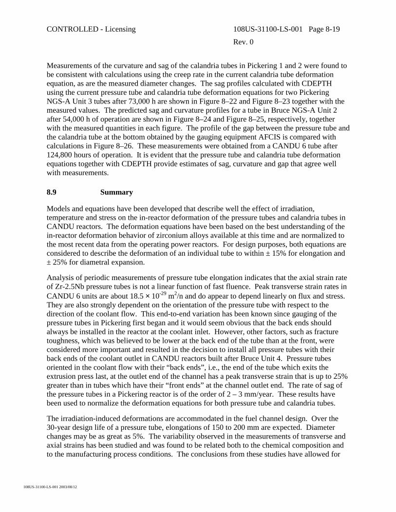
CONTROLLED - Licensing 108US-31100-LS-001 Page 8-19
Rev. 0
108US-31100-LS-001 2003/08/12
Measurements of the curvature and sag of the calandria tubes in Pickering 1 and 2 were found to be consistent with calculations using the creep rate in the current calandria tube deformation equation, as are the measured diameter changes. The sag profiles calculated with CDEPTH using the current pressure tube and calandria tube deformation equations for two Pickering NGS-A Unit 3 tubes after 73,000 h are shown in Figure 8–22 and Figure 8–23 together with the measured values. The predicted sag and curvature profiles for a tube in Bruce NGS-A Unit 2 after 54,000 h of operation are shown in Figure 8–24 and Figure 8–25, respectively, together with the measured quantities in each figure. The profile of the gap between the pressure tube and the calandria tube at the bottom obtained by the gauging equipment AFCIS is compared with calculations in Figure 8–26. These measurements were obtained from a CANDU 6 tube after 124,800 hours of operation. It is evident that the pressure tube and calandria tube deformation equations together with CDEPTH provide estimates of sag, curvature and gap that agree well with measurements.
8.9 Summary
Models and equations have been developed that describe well the effect of irradiation, temperature and stress on the in-reactor deformation of the pressure tubes and calandria tubes in CANDU reactors. The deformation equations have been based on the best understanding of the in-reactor deformation behavior of zirconium alloys available at this time and are normalized to the most recent data from the operating power reactors. For design purposes, both equations are considered to describe the deformation of an individual tube to within ± 15% for elongation and ± 25% for diametral expansion.
Analysis of periodic measurements of pressure tube elongation indicates that the axial strain rate of Zr-2.5Nb pressure tubes is not a linear function of fast fluence. Peak transverse strain rates in CANDU 6 units are about 18.5 × 10⁻²⁹ m2/n and do appear to depend linearly on flux and stress. They are also strongly dependent on the orientation of the pressure tube with respect to the direction of the coolant flow. This end-to-end variation has been known since gauging of the pressure tubes in Pickering first began and it would seem obvious that the back ends should always be installed in the reactor at the coolant inlet. However, other factors, such as fracture toughness, which was believed to be lower at the back end of the tube than at the front, were considered more important and resulted in the decision to install all pressure tubes with their back ends of the coolant outlet in CANDU reactors built after Bruce Unit 4. Pressure tubes oriented in the coolant flow with their “back ends”, i.e., the end of the tube which exits the extrusion press last, at the outlet end of the channel has a peak transverse strain that is up to 25% greater than in tubes which have their “front ends” at the channel outlet end. The rate of sag of the pressure tubes in a Pickering reactor is of the order of 2 – 3 mm/year. These results have been used to normalize the deformation equations for both pressure tube and calandria tubes.
The irradiation-induced deformations are accommodated in the fuel channel design. Over the 30-year design life of a pressure tube, elongations of 150 to 200 mm are expected. Diameter changes may be as great as 5%. The variability observed in the measurements of transverse and axial strains has been studied and was found to be related both to the chemical composition and to the manufacturing process conditions. The conclusions from these studies have allowed for

CONTROLLED - Licensing 108US-31100-LS-001 Page 8-20
Rev. 0
108US-31100-LS-001 2003/08/12
the manufacturing of tubes with better deformation properties and therefore an extension of the design life.
Creep ductility is expected to be very high as the material behaves as a superplastic material as the stress exponent is low. Diametral deformation limits of about 6% are seen to be conservative.
8.10 References
[8.1] S.R. MacEwen and A.R. Causey, Nuclear Technology, 44(1979)118.
[8.2] R.G. Sauvé, Predicting Creep Response of CANDU Fuel Channel Assemblies, Proceedings of the 13th Annual Reactor Simulation Symposium, Canadian Nuclear Society, AECL Report CRNL-4139, April 1987.
[8.3] V. Fidleris, IAEA, Atomic Energy Review, Vol. 13, No. 1, (1975), p. 51-80
[8.4] A.R. Causey, V. Fidleris, S.R. MacEwen and C.W. Schulte, in Influence of Radiation on Material Properties: 13th Int. Symposium, ASTM STP 956, American Society for Testing and Materials, West Conshohocken, PA, 1988, p. 54.
[8.5] N. Christodoulou, A.R. Causey, R.A. Holt, C.N. Tomé, N. Badie, R.J. Klassen, R. Sauvé and C.H. Woo, Zirconium in the Nuclear Industry: 11th Int. Symposium, ASTM STP 1295, American Society for Testing and Materials, West Conshohocken, PA, 1996, p. 518.
[8.6] V. Fidleris, J. Nucl. Mats., 159(1988)22.
[8.7] M. Griffiths, J.F. Mecke and J.E Winegar, Zirconium in the Nuclear Industry: 11th Int. Symposium, ASTM STP 1295, American Society for Testing and Materials, West Conshohocken, PA, 1996, p. 580.
[8.8] F.A. Nichols, J. Nucl. Mats., 30(1969)249.
[8.9] C.E. Coleman, A.R. Causey and V. Fidleris, J. Nucl. Mats., 60(1976) 185.
[8.10] R.A. Holt, A.R. Causey and V. Fidleris, Proceedings of British Nuclear Energy Society Conference, London, 1983, vol. I, p. 175, AECL-7931.
[8.11] P.A. Ross-Ross and C.E.L. Hunt, J. Nucl. Mats., 26(1968)2.
[8.12] D.G. Franklin, Zircaloy-4 Deformation During Power Reactor Irradiation ASTM Spec. Tech. Publ. 754 (1981) p.235.
[8.13] B. Watkins and D.S. Wood, ASTM Spec. Tech. Publ. 458 (1969) p.329.
[8.14] A.R. Causey, R.A. Holt, N. Christodoulou and E.T.C Ho, , Zirconium in the Nuclear Industry: 12th Int. Symposium, ASTM STP 1354, American Society for Testing and Materials, West Conshohocken, PA, 2000, p. 74.
[8.15] A.R. Causey, F.J. Butcher and S.A. Donohue, J. Nucl. Mats., 159(1988)101.

CONTROLLED - Licensing 108US-31100-LS-001 Page 8-21
Rev. 0
108US-31100-LS-001 2003/08/12
[8.16] V. Fidleris, J. Nucl. Mats., 54(1974)199.
[8.17] R.A. Holt, J. Nucl. Mats., 82(1979)419.
[8.18] A.R. Causey, R.A. Holt and S.R. MacEwen, ASTM Spec. Tech. Publ. 824 (1984) p.269.
[8.19] V. Fidleris, A.R. Causey and R.A. Holt, In ’Optimizing Materials for Nuclear Applications’, F.A. Garner, D.S. Gelles and F.W. Wiffen, Eds., Metallurgical Society of AIME, Warrendale, 1985, p.35.
[8.20] A.R. Causey, ASTM Spec. Techn. Publ. 551 (1974) p.263.
[8.21] D.G. Franklin, G.E. Lucas and A.L. Bement, “Creep of Zirconium Alloys in Nuclear Reactors”, ASTM STP 955 (1983).
[8.22] A. Holt and E.F. Ibrahim, Acta Metallurgica, 27(1979)1319.
[8.23] R.A. Holt and A.R. Causey, J. of Nucl. Mats., 150(1987)306.
[8.24] C.N. Tomé, C.B. So and C.H. Woo, Phil. Mag. A, 67(1993)917.
[8.25] N. Christodoulou, A.R. Causey, C.H. Woo, C.N. Tomé, R.J. Klassen and R.A. Holt, in Effects of Radiation on Materials: 16th Int. Symposium, ASTM STP 1175, American Society of Testing and Materials, Philadelphia, 1993, p.1111.
[8.26] R.A. Holt, N. Christodoulou and A.R. Causey, J. Nucl. Mats., 317(2003)256.
[8.27] A.R. Causey, V. Fidleris, S.R. MacEwen and C.W. Schulte, ASTM Spec. Tech. Publ. 956 (1988) p.54.
[8.28] C.N. Tomé, N. Christodoulou, P.A. Turner, M.A. Miller, C.H. Woo, J. Root and T.M. Holden, J. Nucl. Mats., 227(1996)237.
[8.29] J.D. Parker, V. Perovic, M. Leger and R.G. Fleck, ASTM Spec. Tech. Publ. 939 (1987) p.86.
[8.30] R. B. Adamson, Irradiation Growth of Zircaloy, ASTM Spec. Tech. Publ. 633 (1977) p.326.
[8.31] V. Fidleris, R.P. Tucker, and R.B. Adamson, ASTM Spec. Tech. Publ. 939 (1987) p.49.
[8.32] A. Rogerson, J. Nucl. Mats., 159(1988)43.
[8.33] R.A. Holt and R.W. Gilbert, J. Nucl. Mats., 137(1985)185.
[8.34] R.A. Murgatroyd and A. Rogerson, In Proceedings of BNES Conference on Dimensional Stability and Mechanical Behavior of Irradiated Metals and Alloys, London, 2 (1984) p.93.
[8.35] R.A. Murgatroyd and A. Rogerson, J. Nucl. Mats., 90(1980)240.
[8.36] R.A. Holt, J. Nuc. Mats., 159(1988)310.

CONTROLLED - Licensing 108US-31100-LS-001 Page 8-22
Rev. 0
108US-31100-LS-001 2003/08/12
[8.37] R.A, Holt, A.R. Causey, M. Griffiths and E.T.C. Ho, Zirconium in the Nuclear Industry: 12th Int. Symposium, ASTM STP 1354, American Society for Testing and Materials, West Conshohocken, PA, 2000, p. 86.
[8.38] E.F. Ibrahim and R.A. Holt, J. Nucl. Mats., 91(1980)231.
[8.39] R.G. Fleck, R.A. Holt, V. Perovic and J. Tadros, J. Nucl. Mats., 159(1988)75.
[8.40] W.K. Alexander, V. Fidleris and R.A. Holt, ASTM Spec. Techn. Publ. 633 (1977) p.344.
[8.41] C.H. Woo, Proceedings of the Int. Conf. On Materials for Nuclear Reactor Core Applications, London, British Nuclear Energy Society, 1987, p. 65.
[8.42] A.R. Causey, A.G. Norsworthy and C.W. Schulte, Canadian Met. Quart., 24(1985)207.
[8.43] A.R. Causey, C.H. Woo and R.A. Holt, J. Nuc. Mats., 159(1988)225.
[8.44] A.R. Causey, N. Christodoulou, W.G. Davies, M. Griffiths, G.M. McDougall, G.D. Moan, R.A. Ploc and M.P. Puls, Xi’an International Symposium on Zirconium, Xi’an, China, Nov. 2000.
[8.45] K.A. Padmanabhan and G.J. Davies, “Superplasticity”, Materials Research and Engineering, Vol. 2, Springer-Verlag, New York, 1980.
[8.46] J.H. Gittus, “Creep, Viscoelasticity and Creep Fracture of Solids”, John Wiley and Sons, New York, 1975
[8.47] C.E. Ells, E.F. Ibrahim and A.R. Causey, “ Predicting Creep Ductility of Zirconium Alloy Pressure Tubes”, Proceedings of the International Conference on Creep, April 14-18, 1986, Tokyo, organized by JSME, IMechE, ASME and ASTM (also as AECL-9022.)
[8.48] P.A. Ross-Ross and M.J. Pettigrew, Atomic Energy of Canada Limited Report AECL-4404, 1971.
[8.49] R.G. Sauvé, N. Badie, R.A. Holt, Simulation of Fuel Channel Creep Response in CANDU Nuclear Reactors, Proceedings of the 10th International Conference on Structural Mechanics in Reactor Technology (SMIRT), Volume L, pp 219-223, August 1989.
[8.50] N. Badie, G. D. Morandin, R.G. Sauvé, On-line Determination of Optimum Spacer Locations in CANDU Fuel Channels, in PVP-Vol. 385, “Computer Technology – 1999,” Proceedings of the 1999 ASME-PVP Conference, pp 247-253, 1999.
[8.51] D.R. Metzger, N. Badie, T. P. Byrne, R.G. Sauvé, An Overview of Fuel Channel Modeling, in Ontario Hydro Research Review, Number 8, August 1993.
[8.52] R. G. Sauvé and N. Badie, Non-linear Shell Formulation for Time-Dependent Deformation, in PVP-Vol 265, Design Analysis, Robust Methods, and Stress Classification, Proceedings of the 1993 ASME-PVP Conference, pp 267-275, 1993.

CONTROLLED - Licensing 108US-31100-LS-001 Page 8-23
Rev. 0
108US-31100-LS-001 2003/08/12
[8.53] S. Khajehpour, R.G. Sauvé and N. Badie, Inclusion of Local Shell Behavior of Tubes into a Two-Dimensional Beam Approximation of Deformation in Nuclear Fuel Channels, in PVP-Vol. 441, “Computational Mechanics: Developments and Applications – 2002,” Proceeding of the 2002 ASME-PVP Conference, pp 45-54, 2002.

CONTROLLED - Licensing 108US-31100-LS-001 Page 8-24
Rev. 0
108US-31100-LS-001 2003/08/12
Figure 8–1 Temperature Dependence for Creep for Different Zirconium Alloys
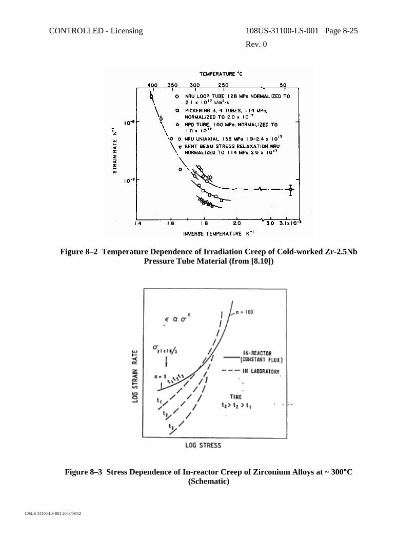
CONTROLLED - Licensing 108US-31100-LS-001 Page 8-25
Rev. 0
108US-31100-LS-001 2003/08/12
Figure 8–2 Temperature Dependence of Irradiation Creep of Cold-worked Zr-2.5Nb Pressure Tube Material (from [8.10])
Figure 8–3 Stress Dependence of In-reactor Creep of Zirconium Alloys at ~ 300°°°°C (Schematic)

CONTROLLED - Licensing 108US-31100-LS-001 Page 8-26
Rev. 0
108US-31100-LS-001 2003/08/12
Figure 8–4 Strain Rate as a Function of Hoop Stress for Internally Pressurized Capsules Irradiated in the Osiris Reactor (from [8.14])

CONTROLLED - Licensing 108US-31100-LS-001 Page 8-27
Rev. 0
108US-31100-LS-001 2003/08/12
Figure 8–5 Stress Dependence of the In-reactor Creep Rate of Cold-worked Pressure Tube Material at 300°°°°C and over a Range of Applied Stresses (from [8.10])
Figure 8–6 Effect of Temperature on the Stress Dependence of Creep of Cold-worked Zr-2.5Nb Pressure Tubes (from [8.10])

CONTROLLED - Licensing 108US-31100-LS-001 Page 8-28
Rev. 0
108US-31100-LS-001 2003/08/12
Figure 8–7 Variation of the Creep Constant, Kc, with Dislocation Density
a) Zr-2.5Nb at 300°°°°C,
b) Zircaloy-2 at 260°°°°C and
c) Zircaloy-2 at 50°°°°C

CONTROLLED - Licensing 108US-31100-LS-001 Page 8-29
Rev. 0
108US-31100-LS-001 2003/08/12
Figure 8–8 Effect of Grain Size on Creep of Zirconium Alloys
a) laboratory creep of Zirconium, b) laboratory creep of Zircaloy-2, c) in-reactor stress-relaxation of cold-worked Zircaloy-2 and Zr-2.5Nb

CONTROLLED - Licensing 108US-31100-LS-001 Page 8-30
Rev. 0
108US-31100-LS-001 2003/08/12
Figure 8–9 Irradiation Growth of Zircaloy-2 Sheet at 60°°°°C Showing Dependence on Texture. Material 199-K slowly cooled from 800°°°°C; material 199-V rapidly cooled from
1020°°°°C
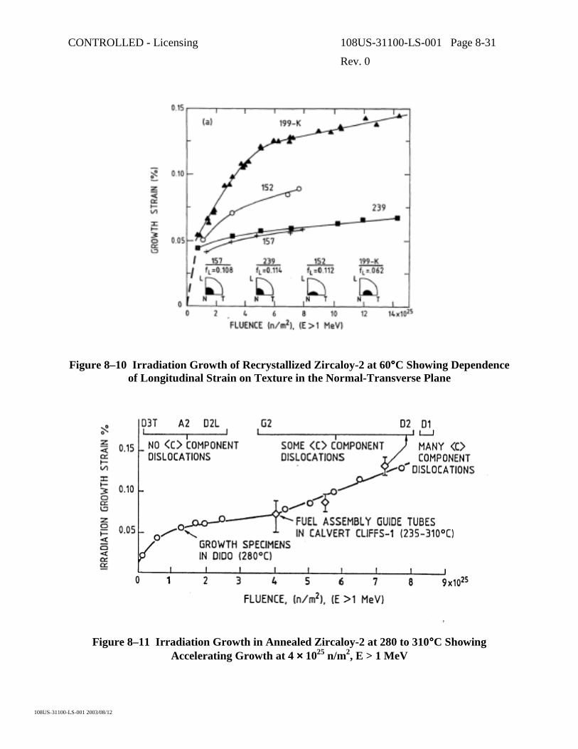
CONTROLLED - Licensing 108US-31100-LS-001 Page 8-31
Rev. 0
108US-31100-LS-001 2003/08/12
Figure 8–10 Irradiation Growth of Recrystallized Zircaloy-2 at 60°°°°C Showing Dependence of Longitudinal Strain on Texture in the Normal-Transverse Plane
Figure 8–11 Irradiation Growth in Annealed Zircaloy-2 at 280 to 310°°°°C Showing Accelerating Growth at 4 ×××× 1025 n/m2, E > 1 MeV

CONTROLLED - Licensing 108US-31100-LS-001 Page 8-32
Rev. 0
108US-31100-LS-001 2003/08/12
Figure 8–12 Irradiation Growth of Annealed and Cold-worked/Stress Relieved Zr-2.5Nb

CONTROLLED - Licensing 108US-31100-LS-001 Page 8-33
Rev. 0
108US-31100-LS-001 2003/08/12
Figure 8–13 Irradiation Growth of Longitudinal and Transverse Specimens of a Darlington Tube Irradiated in Trillium 2 and 3 in Osiris
Figure 8–14 Irradiation Growth of Longitudinal Specimens of a Bruce B Tube Pre-irradiated in Dido and a Bruce A Tube Pre-irradiated in Bruce Unit 2 before
Irradiation in Trillium 2 in Osiris

CONTROLLED - Licensing 108US-31100-LS-001 Page 8-34
Rev. 0
108US-31100-LS-001 2003/08/12
Figure 8–15 Steady-state Irradiation of Zircaloy-2 at 60°°°°C as a Function of Dislocation Density. The numbers beside each data point denote the ratio of <c> to <a> component
dislocations.
0.0E+00
2.0E-08
4.0E-08
6.0E-08
8.0E-08
1.0E-07
1.2E-07
1.4E-07
1.6E-07
1.8E-07
2.0E-07
0 1 2 3 4 5 6
P3J17 meas.
P3J17 pred.
P3K05 meas.
P3K05 pred.
CANDU 6 meas.
CANDU 6 pred.
distance from inlet (m)
diam
tera
l stra
in ra
te (h
-1 ) Back end outlet
Back end inlet
Figure 8–16 Comparison of Measured and Predicted Transverse Strain Rates for the Axial Profiles of Pressure Tubes in Pickering Unit 3 and a CANDU 6 Reactor. Note that one of the Pickering 3 tubes and the CANDU 6 tubes have the back in the outlet, while the other
Pickering 3 tube has the back end in the inlet.

CONTROLLED - Licensing 108US-31100-LS-001 Page 8-35
Rev. 0
108US-31100-LS-001 2003/08/12
0.0E+00
5.0E-08
1.0E-07
1.5E-07
2.0E-07
2.5E-07
0.0E+00 5.0E-08 1.0E-07 1.5E-07 2.0E-07 2.5E-07
C6-1 C6-2C6-3 OPG-1OPG-2 P3J17P3M12 P3K05
mea
sure
d st
rain
rate
h-1
predicted strain rate h-1
Figure 8–17 Comparison of Measured vs. Predicted Diametral Strain Rate from Tubes in a CANDU 6, an OPG 480-channel CANDU and Pickering 3 Units
Figure 8–18 Elongation Data from a CANDU 6 Reactor. The predicted elongation was derived using the pressure tube equation described in Subsection 8.4.2.

CONTROLLED - Licensing 108US-31100-LS-001 Page 8-36
Rev. 0
108US-31100-LS-001 2003/08/12
Figure 8–19 A Plot of the Stress Exponent n against Total Elongation at Failure for Zirconium Alloys at 300 to 450°°°°C. The hatched band is for the results from tensile tests on
many other alloys (from [8.47]).
Pressure Tube1 (origin)
PT West Shift
2 4 6 8 10 12 14 16 18 20 22 24 26 28 30 32 34 36 38 40 42 44
4590
48 50 52 54 56 58 60 62 64 66 68 70 72 74 76 78 80 82 84 86 88
Y
θ
Calandria Tube
Fuel Channel (PT/CT)
Number of Nodes = 83 - 98
Number of Elements = 80 - 96
P/T Centre Line
G/S Coil ThicknessAnnular Gap
X
Bellows Spring
δ (preload)
G/S 2G/S 1 G/S 3 G/S 4
P/T
Initial G/S Clearance
C/T
Element 1Element 45
46
θ
Figure 8–20 Typical CDEPTH Model for Calculation of Fuel Channel Sag Response

CONTROLLED - Licensing 108US-31100-LS-001 Page 8-37
Rev. 0
108US-31100-LS-001 2003/08/12
Figure 8–21 Typical 3D Model for Calculation of Fuel Channel Deformation (spacers are not seen as they are modeled using contact elements)
-25
-20
-15
-10
-5
0
0 1 2 3 4 5 6
Measured
Pred. CT equation
P3J1773000 h
distance from inlet (m)
defle
ctio
n (m
m)
Figure 8–22 Comparison of Measured Sag for Pickering 3 Tube J17 with Calculated Behavior Using the Pressure Tube and Calandria Tube Equations Described in
Subsections 8.5.2 and 8.5.3

CONTROLLED - Licensing 108US-31100-LS-001 Page 8-38
Rev. 0
108US-31100-LS-001 2003/08/12
-35
-30
-25
-20
-15
-10
-5
0
0 1 2 3 4 5 6
Measured
Pred. CT equation
P3M1273000 h
distance from inlet (m)
defle
ctio
n (m
m)
Figure 8–23 Comparison of Measured Sag for Pickering 3 Tube M12 with Calculated Behavior Using the Pressure Tube and Calandria Tube Equations Described in
Subsections 8.5.2 and 8.5.3
-0.035
-0.03
-0.025
-0.02
-0.015
-0.01
-0.005
0
0.0 1.0 2.0 3.0 4.0 5.0 6.0Distance from Inlet (m)
Def
lect
ion
(m)
PredictedMeasuredSpacer Locations
Figure 8–24 Comparison of Measured Pressure Tube Sag in a Tube in Bruce NGS-A Unit 2 after 54,800 Hours with the Sag Calculated Using CDEPTH

CONTROLLED - Licensing 108US-31100-LS-001 Page 8-39
Rev. 0
108US-31100-LS-001 2003/08/12
-0.03
-0.025
-0.02
-0.015
-0.01
-0.005
0
0.005
0.01
0.015
0.02
0.025
0.03
0.0 1.0 2.0 3.0 4.0 5.0 6.0Distance from Inlet (m)
Cur
vatu
re (1
/m)
PredictedMeasuredSpacer Locations
Figure 8–25 Comparison of Measured Pressure Tube Curvature in a Tube in Bruce NGS-A Unit 2 after 54,800 Hours with the Curvature Calculated Using CDEPTH
0.0
1.0
2.0
3.0
4.0
5.0
6.0
7.0
8.0
2500 3500 4500 5500 6500 7500 8500
Distance From A-Face (m)
Gap
(mm
)
CDEPTH
Measured
Figure 8–26 Comparison of Measured with Predicted Gap Obtained from a CANDU 6 Tube after 124,800 Hours

CONTROLLED - Licensing 108US-31100-LS-001 Page 9-1
Rev. 0
108US-31100-LS-001 2003/08/12
9. CORROSION AND HYDROGEN1 INGRESS
9.1 Introduction
In currently operating CANDU reactors, the surfaces of the Zr-2.5Nb pressure tubes are in contact with high-temperature heavy-water coolant on the inside and with carbon dioxide in the annulus gas system on the outside. Design considerations require that corrosion at both surfaces be addressed. The temperature of the heavy water inside the pressure tube ranges from about 250°C at the inlet end in early generation reactors up to about 313°C at the outlet end of today’s CANDU 6 reactors. Addition of LiOD is used to maintain a coolant pHa
2 in the range 10.2<pHa<10.8 (0.35 to 1.4 mg(Li+)/kg(D2O) while between 3 to 10 ml/kg of deuterium (0.5 to 1.6 mg(D2)/kg(D2O)) is maintained to suppress radiolytic production of oxygen in the core. With these deuterium levels, dissolved oxygen concentrations are generally less than 5 µg(O2)/kg(D2O) (<0.003 ml(O2)/kg(D2O)).
In the ACR reactor, while the coolant will be light water and the coolant outlet temperatures will be about 325°C, the coolant will still be maintained alkaline with LiOH, and hydrogen will be added to suppress formation of oxidizing species in the core. The annulus gas will be carbon dioxide with 0.5 to 5.0 vol% oxygen.
A portion (<10%) of the deuterium generated from aqueous corrosion processes on the inside surface of the pressure tube is absorbed by the metal. There is a potential for absorption from the annulus gas side if the gas is insufficiently oxidizing and when deuterium or water is present as an impurity in the carbon dioxide gas.
Each end of the pressure tube is connected to a Type 403 stainless-steel end fitting by a mechanical rolled joint (Figure 9-1). Additional accumulation of deuterium, in the metal at the ends of the tube, occurs under the rolled joints as a consequence of galvanic and crevice effects between the Zr-2.5Nb pressure tube and stainless-steel end fitting. A typical deuterium profile measured along a Zr-2.5Nb pressure tube after 14 Effective Full Power Years (EFPY) of service is shown in Figure 9-2. The contribution of deuterium uptake from the rolled joints is quite evident compared to uptake from corrosion processes along the body of the tube.
1 Deuterium is the principal hydrogen isotope that is absorbed during operation of
CANDU-PHW reactors because heavy water is used as the heat transport coolant. However, much of the zirconium alloy research has been performed using light water. It is assumed that the isotopic differences in the behaviour of 1H and 2H (i.e., D) in zirconium metal are insignificant compared to other effects such as trace impurities in the metal, etc. Generically, in this report, when expressions “hydrogen ingress” and “hydriding” are used, they can be referring to either hydrogen isotope.
2 For heavy water solutions, acidity is often quoted in terms of the pH(apparent), written pHa. This is the pH reading for a heavy water solution at 25°C on a pH meter calibrated with light water buffers.

CONTROLLED - Licensing 108US-31100-LS-001 Page 9-2
Rev. 0
108US-31100-LS-001 2003/08/12
Since excessive deuterium uptake can have deleterious effects on the pressure tube, one of the objectives of chemistry control in the heat transport coolant and annulus gas is to minimize the ingress of hydrogen isotopes into the pressure tube.
Corrosion and deuterium ingress in in-service CANDU pressure tubes are being monitored with time through surveillance programs. Periodic removal of single tubes from service for comprehensive examination provides data on both corrosion and deuterium ingress. In-situ pressure tube micro-sampling (also known as ‘scrapes’ – this involves cutting thin samples of metal from the inside surface of the tube) is carried out to provide a survey of deuterium ingress that can be used for core assessments. These data are also supplemented with results from laboratory tests and in-reactor loop experiments. Through both sources, a better understanding is evolving and the capability for predicting corrosion and hydrogen1 ingress is being improved.
9.2 Pressure Tube Corrosion and Hydrogen Ingress
9.2.1 Waterside Corrosion and Hydrogen Ingress
Zirconium alloys react with water to form a zirconium oxide surface film and hydrogen.
Zr + 2H2O → ZrO2 + 4H
This oxidation process leads to metal loss (i.e., wall thinning), and hydrogen uptake by the metal. The amount of wall thinning is structurally insignificant and is well within the corrosion allowance. The fraction of corrosion-freed hydrogen3 absorbed by the alloy is dependent on both the chemistry of the coolant and the microstructure and composition of the alloy. When the absorbed hydrogen in the zirconium alloy exceeds the hydrogen solubility limit at operating temperature, delayed hydride cracking becomes a potential crack growth mechanism at operating temperature.
The original pressure tubes used in early CANDU reactors were manufactured from Zircaloy-2 and have since been replaced by Zr-2.5Nb pressure tubes. In the more recent reactors, the pressure tubes are manufactured from Zr-2.5Nb, which possesses greater resistance to corrosion in high temperature water. More importantly, less than 10% of the corrosion-freed hydrogen is incorporated into Zr-2.5Nb compared to 30%, or more, for Zircaloy-2 [9.1]. The hydrogen uptake process in Zircaloy-type alloys is thought to involve the discharge of protons and subsequent absorption of hydrogen atoms at second-phase intermetallic particle sites [9.2]. The particles in Zr-2.5Nb are of a different composition and their volume fraction is much lower than in Zircaloy.
The data presented in Figure 9-3 and Figure 9-4 were acquired from removed pressure tubes, and illustrate the benefit of Zr-2.5Nb over Zircaloy-2 in the corrosion and deuterium uptake
3 The amount of hydrogen incorporated is often expressed as a percentage of the
theoretical amount of corrosion-freed hydrogen.

CONTROLLED - Licensing 108US-31100-LS-001 Page 9-3
Rev. 0
108US-31100-LS-001 2003/08/12
performance of pressure tubes. For pressure tubes made from Zircaloy-2, an accelerated corrosion rate was observed once the oxide grew beyond 10 to 13 µm thick. A radiolytically generated oxidizing water chemistry inside the thick porous oxide has been postulated to account for the accelerated corrosion rate [9.3]. Cold-worked Zr-2.5Nb pressure tubes show a different oxidation behavior approximating paralinear kinetics that has been interpreted as indicative of a mechanism controlled by diffusion through a thin barrier oxide layer of constant thickness close to the metal-oxide interface4. With up to 14 EFPY of operational experience with Zr-2.5Nb pressure tubes in CANDU reactors, there is little indication of a sudden acceleration in corrosion rate. There are, however, indications of a slight upward trending in the deuterium uptake rate in some of the data from repeat micro-sampling campaigns. This is consistent with recent analyses of Zr-2.5Nb pressure tubes removed from CANDU reactors after approximately 9 EFPY of service that show a slight increase in the oxide growth rate5 [9.4]. In the past, most of the short-term projections of deuterium ingress behavior have been made using ingress rates that are constant with time and based upon the lifetime average rate of ingress.
The maximum linear corrosion rate (expressed as oxide growth rate) obtained from the data presented in Figure 9-4 is approximately 1.4 µm of oxide per year for Zr-2.5Nb pressure tubes. Assuming no acceleration in oxidation over a 25 EFPY in-service operating lifetime of the pressure tube, the maximum amount of metal loss is 0.026 mm (taking into account the oxide volume created per unit volume of metal).
As evident from the deuterium profile for the body of the tube (not impacted by ingress from the rolled joint region), the deuterium uptake (Figure 9-2) and thickness of the surface oxide varies along the length of each pressure tube. In CANDU reactors, maximum oxidation on the inside surface occurs near the outlet end of the tube, a consequence of both the magnitude of the fast neutron flux and an increasing temperature of the coolant as it passes through the channel. Based on scrape data taken at the 2, 4 and 5 m axial positions (as measured from the inlet end) along many CANDU 6 pressure tubes6, the deuterium uptake appears to follow an Arrhenius-type temperature dependence (Figure 9-5), with an apparent activation energy near 1.2×10⁵ Joule/mole. However, it should be recognized that this apparent Arrhenius dependence reflects the complex interaction of a number of factors, some of which are:
1. The influence of temperature on corrosion (which, for Zr-2.5Nb in short-term loop tests [9.5] [9.6], appears to have an activation energy near (0.3 to 0.4)×105 Joule/mole) and hydrogen ingress.
4 In zirconium corrosion, the oxide layer grows inwards from the oxide–metal interface
rather than from the oxide-coolant interface. 5 Zr-2.5Nb oxides tend to spall significantly more than those on Zircaloy-2. In
examination of surveillance tubes, oxide thickness determinations for Zr-2.5Nb tubes are made on areas where the oxide appears to be intact.
6 This region is not influenced by the deuterium that has been incorporated through the rolled joint.

CONTROLLED - Licensing 108US-31100-LS-001 Page 9-4
Rev. 0
108US-31100-LS-001 2003/08/12
2. The influence of the thickness of surface oxide [9.6] (which varies along the tube) on corrosion and hydrogen ingress.
3. The influence of flux and fluence on the oxide and microstructure of the tube and the corresponding influence on corrosion [9.7] and hydrogen ingress.
9.2.2 In-Reactor Loop Tests to Study Corrosion and Hydrogen Ingress into Zr-2.5Nb
Research into the corrosion and hydrogen ingress characteristics of zirconium alloys used as pressure tube materials has been carried out at the Chalk River Laboratories of AECL and within the CANDU community for more than 40 years. A great deal of the information obtained through this research has been published in the open literature.
Currently, high-temperature corrosion tests of zirconium alloys are being conducted using the light-water cooled, fuelled U-2 loop in the NRU reactor at AECL-CRL, and the AECL owned heavy-water loop in the OECD Halden Boiling Water Reactor in Halden, Norway. The objectives of these test programs are:
1. To optimize the coolant chemistry for current reactors to maximize the operating life of Heat Transport System materials.
2. To determine origins of tube-to-tube variability in corrosion and hydrogen ingress characteristics of Zr-2.5Nb with the aim of generating improved material specifications for future pressure tube production.
3. To provide information for the empirical, mathematical model being developed to predict deuterium ingress into Zr-2.5Nb pressure tubes in CANDU reactors (Subsection 9.2.2.1). The model is employed in fitness-for-service assessments for in-service pressure tubes as well as in the development of specifications for pressure tubes for new reactor designs including ACR. The current tests at Halden span the range of ACR coolant operating conditions.
9.2.2.1 The Pressure Tube Hydrogen Ingress Model
The mechanisms of in-reactor corrosion and hydrogen ingress in Zr-2.5Nb are complex, and depend on a number of variables such as: temperature; neutron flux; water chemistry; surface oxide thickness; microstructure and microchemistry of both the oxide and alloy substrate.
Information on these different mechanisms is being incorporated into the empirical mathematical model being developed to model/predict the corrosion and hydrogen/deuterium uptake in Zr-2.5Nb pressure tubes. The approach used to assess the oxidation and hydrogen/deuterium ingress behavior of pressure tubes to design life is to simulate the behavior by measuring the response of pre-oxidized (pre-filmed) coupons, prepared from pressure tubes, exposed to high temperature water under irradiation in short-term in-reactor tests.
This predictive model is based on a functional relationship between the oxidation rate in high temperature water and the oxide thickness [9.6], using data obtained from the in-flux and out-of-
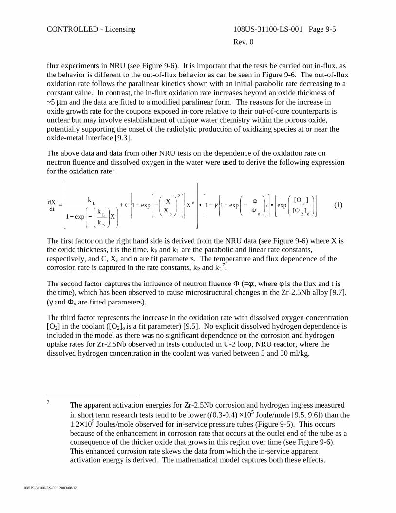
CONTROLLED - Licensing 108US-31100-LS-001 Page 9-5
Rev. 0
108US-31100-LS-001 2003/08/12
flux experiments in NRU (see Figure 9-6). It is important that the tests be carried out in-flux, as the behavior is different to the out-of-flux behavior as can be seen in Figure 9-6. The out-of-flux oxidation rate follows the paralinear kinetics shown with an initial parabolic rate decreasing to a constant value. In contrast, the in-flux oxidation rate increases beyond an oxide thickness of ~5 µm and the data are fitted to a modified paralinear form. The reasons for the increase in oxide growth rate for the coupons exposed in-core relative to their out-of-core counterparts is unclear but may involve establishment of unique water chemistry within the porous oxide, potentially supporting the onset of the radiolytic production of oxidizing species at or near the oxide-metal interface [9.3].
The above data and data from other NRU tests on the dependence of the oxidation rate on neutron fluence and dissolved oxygen in the water were used to derive the following expression for the oxidation rate:
(1)o2
2
o
n2
o
P
L
L
]O[
]O[expexp11X
XXexp1C
Xk
kexp1
kdt
dX
����
�
�
����
�
�
����
�
�
����
�
�
���
��
���
���
����������
�
�
����������
�
�
��
�
��
��
�
��
�
�����
�
�
�����
�
�
����
�
�
����
�
� ��
�
�
��
�
�•
��
�
�
��
�
�
ΦΦ−−−•
��
�
�
��
�
�−−+
��
�
�
��
�
�−−
= γ
The first factor on the right hand side is derived from the NRU data (see Figure 9-6) where X is the oxide thickness, t is the time, kP and kL are the parabolic and linear rate constants, respectively, and C, Xo and n are fit parameters. The temperature and flux dependence of the corrosion rate is captured in the rate constants, kP and kL
7.
The second factor captures the influence of neutron fluence Φ (=φt, where φ is the flux and t is the time), which has been observed to cause microstructural changes in the Zr-2.5Nb alloy [9.7]. (γ and Φo are fitted parameters).
The third factor represents the increase in the oxidation rate with dissolved oxygen concentration [O2] in the coolant ([O2]o is a fit parameter) [9.5]. No explicit dissolved hydrogen dependence is included in the model as there was no significant dependence on the corrosion and hydrogen uptake rates for Zr-2.5Nb observed in tests conducted in U-2 loop, NRU reactor, where the dissolved hydrogen concentration in the coolant was varied between 5 and 50 ml/kg.
7 The apparent activation energies for Zr-2.5Nb corrosion and hydrogen ingress measured
in short term research tests tend to be lower ((0.3-0.4) ×105 Joule/mole [9.5, 9.6]) than the 1.2×10⁵ Joules/mole observed for in-service pressure tubes (Figure 9-5). This occurs because of the enhancement in corrosion rate that occurs at the outlet end of the tube as a consequence of the thicker oxide that grows in this region over time (see Figure 9-6). This enhanced corrosion rate skews the data from which the in-service apparent activation energy is derived. The mathematical model captures both these effects.

CONTROLLED - Licensing 108US-31100-LS-001 Page 9-6
Rev. 0
108US-31100-LS-001 2003/08/12
The oxidation rate (Equation (1)) is integrated to give the oxidation kinetics. Hydrogen ingress is modeled by assuming that the metal absorbs a fraction of the hydrogen produced during oxidation, i.e., the hydrogen uptake (H in mg/kg) is proportional to oxidation (X in µm of oxide):
H = αFX (2)
where α is the percent theoretical uptake3, and F is a constant capturing sample thickness, chemical stoichiometry and unit conversions. There is evidence from in- and out-reactor tests that α increases with temperature and flux. For simplicity, it is assumed that α varies along the pressure tube and the temperature and flux dependence of α is determined through a fit to pressure tube deuterium data from surveillance and monitoring programs.
Model predictions of the deuterium concentration profile along a CANDU PHW pressure tube are compared to measured data in Figure 9-7; the overall agreement is satisfactory and the predicted variation with time is consistent with measurement. In Figure 9-8, model predictions of deuterium concentration as a function of time near the outlet end (where the maximum uptake occurs) are compared to pressure tube data. The model predicts a gradual increase in the deuterium pickup rate that is consistent with reactor data. In addition to the mean deuterium concentration, the plot shows the 95% upper and lower prediction limits (UPL and LPL).
In summary, a hydrogen ingress model exists to predict the deuterium buildup in the body of pressure tubes for fitness-for-service assessments and for assessments of design changes aimed at reducing deuterium buildup (or hydrogen buildup in the ACR case). The model predicts gradually increasing deuterium ingress with time, consistent with data from operating reactors. It also predicts, through its temperature and flux dependence, the formation of deuterium peaks observed at the outlet ends of some pressure tubes. The model and its database are continually improved and updated as information and data from Research and Development programs and from operating reactors become available.
9.2.2.2 Development of Improved Pressure Tubes
The objective of the more fundamental corrosion studies on Zr-2.5Nb in high temperature water is to develop a mechanistic understanding of how various factors impact on the corrosion and hydrogen ingress processes. Understanding these processes can lead to refinements to the current Zr-2.5Nb material that will improve the performance of new pressure tubes in current and future CANDU reactors.
The corrosion and deuterium ingress experiments conducted in the AECL heavy-water loop at the OECD Halden reactor have focused on the effects of material variables on corrosion and deuterium uptake in Zr-2.5Nb. The experiments were conducted using test channels at temperatures of 250°C and 325°C8 [9.6] in low-flux, high-flux and out-of-flux sites.
8 These temperatures span the temperature range for the Heat Transport System in ACR.
In ongoing tests, the upper temperature has been raised to 335°C.

CONTROLLED - Licensing 108US-31100-LS-001 Page 9-7
Rev. 0
108US-31100-LS-001 2003/08/12
One factor that is beginning to emerge from these tests is the difference between β-quenched9 and non-β-quenched Zr-2.5Nb [9.8]. Over the testing period evaluated to date (~550 days), coupons prepared from β-quenched material have shown much lower oxide growth rates, in and out-of-flux, than coupons prepared from non-β-quenched material [9.8]. Deuterium uptake was also lower for β-quenched material tested at 325°C, in-flux and out-of-flux. The effect of β-quenching on deuterium uptake is less clear at 250°C as coupons exposed out-of-flux at 250°C show a significant increase in deuterium uptake over a 320-day test period. This observation will continue to be assessed as the tests progress.
It has been recognized that minor alloying additions such as carbon (C) and iron (Fe) have a significant influence on the corrosion and deuterium uptake of Zr-2.5Nb [9.9] [9.10] [9.11]. To determine the optimum Fe/C concentrations, corrosion experiments involving Zr-2.5Nb (Fe, C) drop castings were conducted in-flux in the OECD Halden reactor. The corrosion and deuterium uptake response of the drop castings was determined over the concentration range 150 to 3000 mg/kg Fe and 30 to 300 mg/kg C for up to 450 days exposure in 325°C coolant.
A statistical evaluation of the results using the Response Surface Analysis (RSA) technique has shown that the corrosion and the deuterium uptake followed a quadratic dependency on the Fe and C concentrations. This is demonstrated in Figure 9-9 where a series of sections through the response surface are projected onto a two dimensional plane to show the influence of the Fe and C concentration on deuterium uptake in Zr-2.5Nb. Figure 9-9 also indicates that by lowering the C and increasing the Fe concentration from current CANDU 6 concentrations, significant reductions in the deuterium uptake should be achieved. Although the microstructure of the drop castings is not representative of pressure tubes, out-reactor experiments on micro-pressure tubes (with similar microstructure to pressure tubes) have also shown similar results when the data have been evaluated by RSA (i.e., quadratic dependence on Fe and C concentration). Corrosion testing of micro-pressure tubes in the AECL owned loop in the Halden reactor will further define the Fe and C content for pressure tubes in future CANDU reactors such as ACR.
An example of how detailed research into corrosion mechanisms has lead to important insights is the effect of the oxide microstructure on deuterium ingress and how modifications to the surface structure of a pressure tube may be used to reduce deuterium ingress. Transmission electron microscopy examination of oxide cross-sections on corroded Zr-2.5Nb surfaces has shown that there are two main types of porosity: ‘flake’ and ‘ribbon’ [9.12] [9.13]. Flake porosity develops at the boundaries of columnar oxide crystallites formed from the α-Zr grains while ribbon porosity develops along the corroded α/β grain boundaries (Figure 9-10). This ribbon porosity forms a continuous path, or conduit, for the coolant to diffuse from the coolant-oxide interface down to the oxide-metal interface. It is postulated that this type of porosity is the primary pathway culminating in deuterium ingress. The nature of the ribbon porosity is controlled by the
9 The current fabrication route for CANDU pressure tubes involves β-quenching.
β-Quenching refers to heating the Zr-2.5Nb logs (or sometimes hollow billets) into the β-phase region (~1020°C), then quenching in water. This serves to homogenise the billet and refine the structure of the α-Zr grains.
CONTROLLED - Licensing 108US-31100-LS-001 Page 9-8
Rev. 0
108US-31100-LS-001 2003/08/12
shape and distribution of the β-Zr filaments in the alloy. Modifications to the structure of the β-Zr phase in Zr-2.5Nb pressure tubes (such as heat treating or shot peening) during the final stages of fabrication result in less inter-connected ribbon porosity being formed during in-service corrosion. Tests on shot-peened coupons are ongoing in the Halden reactor to evaluate if the corrosion and deuterium uptake is lower.
As discussed in Section 6, the Fe and C content of pressure tubes for advanced reactor designs will be specified to take advantage of the research and development results.
9.2.3 Annulus Gas Side Corrosion and Hydrogen Ingress
The objective of the chemistry control of the annulus gas system is to maintain:
1. The protective oxide on the outside surface of the pressure tube to minimize the ingress of deuterium or hydrogen (from impurities in the annulus gas) into the Zr-2.5Nb alloy.
2. A dew point less than -10°C to facilitate the detection of any water leaks.
Nitrogen was the gas initially chosen to fill the annulus between the calandria and pressure tubes, but it has since been replaced with carbon dioxide in all CANDU reactors. A number of drawbacks with nitrogen as the annulus gas were encountered:
1. The resistance of the oxide, on the outside of the pressure tube, towards hydrogen ingress, could not be maintained, and hydrogen or deuterium was able to enter the pressure tube body (D2/H2 concentrations in the nitrogen annulus gas were up to 1 vol%)10.
2. In the presence of water, nitric acid was radiolytically produced and this lead to degradation of some structural components.
3. Nitrogen-12 became activated to form a carbon-14 dust that complicated the pressure tube replacements in some of the Pickering A units.
The initial experience with a carbon-dioxide-filled annulus lead to deposits of organic material in the cooler regions of the annulus gas system. This deposition of organic material in the “pig tails” could block the gas flow, thereby leaving the annulus gas stagnant. A stagnant annulus gas system not only compromised leak detection, but also potentially provided a reducing environment that could not maintain the resistance of the surface oxide towards hydrogen uptake.
Two possible sources of the organic material were identified: radiolytic synthesis involving carbon dioxide, and oils and greases left behind from construction. The addition of oxygen to the re-circulating carbon dioxide was recommended to remove any existing organic material and prevent formation and deposition of further material. Most CANDU reactors now maintain 0.5-5.0 vol% oxygen in the annulus gas system. The addition of this oxygen ensures that any hydrogen or deuterium gas that enters the annulus gas system is recombined to form water. The
10 The high deuterium concentration found in pressure tube P3L09 (See Figure 9-3) is
thought to have arisen by ingress of deuterium through the degraded outside surface oxide.

CONTROLLED - Licensing 108US-31100-LS-001 Page 9-9
Rev. 0
108US-31100-LS-001 2003/08/12
added advantage of oxygen additions is that it provides further insurance that the protective surface oxide on the outside of the pressure tube is maintained.
Adherence to the current annulus gas practice ensures that the deuterium/hydrogen uptake from the annulus gas side of the pressure tube is insignificant compared to that from the waterside corrosion processes.
9.2.4 Summary of Pressure Tube Corrosion and Hydrogen Ingress
The waterside corrosion behavior of a Zr-2.5Nb pressure tube is a function of temperature, coolant chemistry and fast neutron irradiation. The waterside corrosion rate increases along the length of a CANDU pressure tube as the temperature rises from inlet to outlet. Dissolved deuterium is maintained in the CANDU heat transport coolant to ensure that oxygen is not produced by radiolysis as oxidizing conditions in the core must be avoided to minimize waterside corrosion. Deuterium uptake from waterside corrosion is exceptionally low in Zr-2.5Nb compared to Zircaloy-2. After 16 years at operating temperatures in a CANDU 6 reactor, the maximum observed deuterium concentration due to uptake is below 50 mg/kg (Figure 9-8).
In the annulus gas, the oxidation rates on the outside of the pressure tube are low. However, care must be taken to avoid hydrogen ingress by keeping the annulus gas sufficiently oxidizing in order to maintain a protective oxide film as a barrier to hydrogen ingress. The current carbon dioxide annulus gas to which 0.5-5.0 vol% oxygen is added ensures a slow, but continuous oxidation of the outside surface such that hydrogen uptake from the annulus gas is insignificant compared to the waterside corrosion processes.
9.3 Hydrogen Ingress at Rolled Joints
9.3.1 Background
Enhanced deuterium pickup in the pressure tube in the area of the rolled joints was first noted in tubes removed from CANDU reactors at the Pickering site following some pressure tube leaks in 1974. An example of the enhanced uptake near the rolled joint is shown in Figure 9-2. The deuterium concentration profiles at the ends of the pressure tube result from deuterium diffusion inboard from points of ingress at the rolled joint. Understanding the factors causing this enhanced deuterium ingress in order to predict the likelihood of crack initiation and growth from potential flaws in this zone by DHC (see Section 12) was seen to be important. This was particularly true for those reactors built prior to the development of the low-stress zero-clearance rolled joint11 and for those CANDU reactors that have 13 fuel bundles in the fuel channel. In the latter case, the bearing pads of the inlet and outlet bundle rest in the roll joint region and the potential exists to generate flaws in the pressure tube by a fretting mechanism.
11 Low-stress zero-clearance rolled joints are standard in CANDU 6 reactors and will be
used in future reactors.
CONTROLLED - Licensing 108US-31100-LS-001 Page 9-10
Rev. 0
108US-31100-LS-001 2003/08/12
The desire to reduce susceptibility of any part of the pressure tube to DHC while at operating temperature by maintaining hydrogen isotope concentrations below the solubility limit has led to a need for a predictive model for this enhanced ingress at the rolled joint regions. The following sections describe the current predictive capability.
9.3.2 Mechanisms of Hydrogen Ingress at Rolled Joints
Laboratory experiments as well as out-reactor loops involving small diameter or full-sized rolled joints are continuing to provide information on the mechanisms of deuterium ingress into the pressure tubes at the rolled joint. In addition, examination of pressure tubes removed from reactors has also contributed useful information on deuterium ingress at the rolled joint. The results have shown that rolled-joint ingress depends on a number of factors including:
1. Characteristics of the crevice between the pressure tube and end fitting,
2. Water chemistry in the crevice, and
3. Galvanic effects between the pressure tube and end fitting.
9.3.2.1 Sources and Routes of Hydrogen Ingress
Under CANDU operating conditions, the primary source for deuterium ingress is the enhanced corrosion in the crevices between the galvanically coupled pressure tube and end fitting. The galvanic couple leads to the cathodic reduction of the heavy-water coolant on the end fitting steel surface and some of the deuterium enters the end fitting. When a rolled joint is made, the thin oxide on both the inside and outside of the pressure tube does not remain intact. Regions of metal-to-metal contact with the end fitting are developed, particularly at the regions of the grooves in the end fitting. In-service, most of the oxide is regenerated, with the exception of the regions of intimate contact. Early in life, deuterium can enter the pressure tube directly through un-repaired areas in the oxide. When only areas of intimate contact remain un-oxidized, deuterium ingress occurs predominantly by diffusion through the end fitting to these contact areas. The possible routes for deuterium ingress, depicted in Figure 9-11, are: direct pickup as a result of general corrosion (Route 1), deuterium produced by enhanced corrosion along the crevice between the pressure tube and end fitting and direct entry into the pressure tube (Route 2), and deuterium migrating through the end fitting hub and into the pressure tube (Route 3). Although direct pickup of deuterium along the pressure tube inside surface due to corrosion (Route 1) is always operative, the observed peaks in the deuterium profiles suggest that Routes 2 and 3 are the principal routes of ingress. For clarity, Figure 9-11 shows ingress by Routes 2 and 3 at one location only; however, ingress could occur via these two routes at all locations where there are crevices and regions of metal-to-metal contact.

CONTROLLED - Licensing 108US-31100-LS-001 Page 9-11
Rev. 0
108US-31100-LS-001 2003/08/12
9.3.3 Modeling Hydrogen Build-up at Rolled Joints
9.3.3.1 Model Development
The model [9.14] uses a database that has been compiled from pressure tubes removed from CANDU reactors. From the measured deuterium concentration profile in the rolled joint region of each pressure tube, the total amount of deuterium picked up, the contributions from ingress at the rolled joint and corrosion along the pressure tube [9.14], and the corresponding pickup rates can all be estimated. Using these ingress rates, the model solves the diffusion equation taking into account hydride precipitation. The model also incorporates super-saturation effects through the use of a terminal solid solubility (TSS) for hydrogen in Zr-2.5Nb that has different values depending whether hydrides are being dissolved or formed (corresponding to whether the alloy is increasing or decreasing in temperature).
Figure 9-12 illustrates the quality of the fit. Here the measured hydrogen equivalent12 concentration profiles are compared to model calculations for the inlet and outlet rolled joints of a pressure tube after approximately 17 years.
While the rolled joint ingress rates are not known apriori, model predictions are based on rates determined from removed CANDU pressure tubes. Results of out-reactor loop tests and pressure tube data [9.14] indicate that the rate of ingress in the rolled joints may be declining with time. This decline may be due to the repair of the oxide layer on the pressure tube that was damaged during rolling (allowing enhanced ingress). The deuterium ingress rate, R, is assumed to be inversely proportional to the oxide thickness which in turn is considered to follow a parabolic law in time, t, as follows:
bat1)t(R ½ +
=
The constants a and b are determined from a least-squares fit to the measured mass of deuterium picked up and the results are shown in Figure 9-13 for both the inlet and outlet ends.
9.3.3.2 Model Predictions
The rolled joint ingress model is used to predict lifetime deuterium build-up in CANDU pressure tubes. For conservatism, upper bound values are used for: rolled joint ingress rates (Figure 9-13), deuterium pickup rates due to corrosion, and initial hydrogen concentration.
It should be noted that, whereas ingress rates have a major effect on the deuterium build-up under the rolled joint, the effect in the region of the rolled joint with the highest residual stress (at the end of rolling, 70 to 80 mm from the pressure tube end) is considerably less pronounced.
12 As engineering units of weight are normally used for concentration of hydrogen isotopes
in zirconium alloys (as opposed to atomic units), hydrogen equivalent is defined as {[H] + ½ [D]}where the concentration units are in ppm (i.e., mg/kg).
CONTROLLED - Licensing 108US-31100-LS-001 Page 9-12
Rev. 0
108US-31100-LS-001 2003/08/12
The main objective of the model is to predict when TSS will be exceeded and hydrides are present inboard of the rolled joint at the burnish mark (end of rolled region) at operating temperature. The model is also used to examine ways to extend pressure tube life in future reactors. This includes evaluating:
1. Increasing the pressure tube wall thickness at the tube ends;
2. Moving the burnish mark further inboard; and,
3. Reducing deuterium uptake due to corrosion by optimizing the pressure tube material properties.
To present model predictions concisely, it is instructive to represent deuterium build-up along the pressure tube in terms of the propagation of the ‘hydride front’. Figure 9-14 depicts the rolled joint and the hydrogen equivalent concentration profile along the end of the pressure tube. The TSS line divides the tube into two regions:
1. A two-phase region where TSS is exceeded and hydrides are present; and,
2. A region with no hydrides.
The boundary between these two regions is referred to as the hydride front. With time, the hydrogen equivalent concentration profile shifts upward causing the hydride front to move inboard13.
Model predictions of the hydride front propagation at the outlet end of a CANDU 6 pressure tube are shown in Figure 9-15. After about 10 hot years, hydrides begin to be present at operating temperatures in the compressive-stress zone of the joint. There is an initial rapid inboard propagation of the hydride front (25 to 50 mm from the pressure tube end) that is principally governed by rolled joint ingress. Further propagation inboard is subsequently determined by diffusion of the deuterium from the rolled joint region and by deuterium ingress from corrosion. The model is used to evaluate the potential effects of any proposed changes to the rolled-joint design on hydrogen concentrations near the ends of the pressure tubes for the channel design life.
The results of on-going work, including the analysis of more rolled joints and TSS studies, are incorporated into the model to update the predictions which can then be used in quantitative assessments of deuterium concentrations in the ends of pressure tubes.
9.3.4 Summary of Hydrogen Ingress at Rolled Joints
Additional deuterium ingress occurs at the pressure tube ends as a result of the galvanic/crevice contact between the zirconium alloy pressure tube and the stainless steel end fitting. A mathematical model exists for predicting deuterium build up in the rolled joint region of pressure tubes for fitness-for-service assessments. Measured deuterium concentration profiles in pressure tubes removed from operating reactors are used to determine ingress rates. The reactor data, and
13 Note that the time required for the hydride front to reach a given location along the
pressure tube is the time it takes to reach TSS at that location.

CONTROLLED - Licensing 108US-31100-LS-001 Page 9-13
Rev. 0
108US-31100-LS-001 2003/08/12
data from out-reactor loop tests, show that the rolled joint ingress rate is declining with time. The model and its database are continually updated as information becomes available from Research and Development programs and from pressure tube surveillance programs. At present, zero-clearance rolled joints are used to ensure low residual stresses after rolling and deuterium build up at rolled joints is monitored by surveillance.
CONTROLLED - Licensing 108US-31100-LS-001 Page 9-14
Rev. 0
108US-31100-LS-001 2003/08/12
9.4 References
[9.1] V.F. Urbanic, B. Cox, and G.J. Field, “Long Term Corrosion and Deuterium Uptake in CANDU-PHW Pressure Tubes”, Zirconium in the Nuclear Industry: Seventh International Symposium, ASTM STP 939, 1987, pp. 189-205. R.B. Adamson and L.F.P. Van Swan, Eds.
[9.2] International Atomic Energy Agency “Waterside Corrosion of Zirconium Alloys in Nuclear Power Plants” 1998 AEA Report IAEA-TECDOC-996
[9.3] A.B. Johnson Jr., “Thick-film Effects in the Oxidation and Hydriding of Zirconium Alloys”, Presentation at the IAEA Technical Committee Meeting “Fundamental Aspects of Corrosion of Zirconium-Based Alloys in Water Reactor Environments”, Portland, Oregon, Sept. 11-15, 1989. pp. 107-120.
[9.4] I.J. Muir, W.H. Hocking, D. Khatamian and V.F. Urbanic “ Elucidating Oxidation Mechanisms of Irradiated Zirconium Alloys using Surface Analytical Methods”. Presented at the Tenth International Conference of Environmental Degradation of Materials in Nuclear Power Systems – Water Reactors. Lake Tahoe, 2001. Available as AECL Report AECL-2136.
[9.5] V.F. Urbanic, R. Choubey, and C.K. Chow, “Investigation of Variables that Influence Corrosion of Zirconium Alloys during Irradiation”, Zirconium in the Nuclear Industry: Ninth International Symposium, ASTM STP 1132, 1991, pp 665-682. C.M. Eucken and A.M. Garde, Eds.
[9.6] G.M. McDougall, V.F. Urbanic, and O. Aarrestad, “Studies of Zirconium Alloy Corrosion and Hydrogen Uptake during Irradiation” Zirconium in the Nuclear Industry: Twelfth International Symposium, ASTM STP 1354, 2000, pp 756-772. G.P. Sabol and G.D. Moan, Eds.
[9.7] V.F. Urbanic, and M. Griffiths, “Microstructural Aspects of Corrosion and Hydrogen Ingress in Zr-2.5Nb”, Zirconium in the Nuclear Industry: Twelfth International Symposium, ASTM STP 1354, 2000, pp 641-657. G.P. Sabol and G.D. Moan, Eds.
[9.8] G.M. McDougall, and V.F. Urbanic, “The Influence of Material Variables on the Corrosion and Deuterium Uptake of Zr-2.5Nb Alloy during Irradiation” Zirconium in the Nuclear Industry: Thirteenth International Symposium, ASTM STP 1423, 2002, pp 247-273. G.D. Moan and P. Rudling, Eds.
[9.9] R.A. Ploc, “The Effect of Minor Alloying Elements on Oxidation and Hydrogen Pickup in Zr-2.5Nb,” Zirconium in the Nuclear Industry: Thirteenth International Symposium, ASTM STP 1423, 2002, pp. 297-312. G.D. Moan and P. Rudling, Eds.
[9.10] R.A. Ploc, “Residual Carbon Impurities in Zr-2.5Nb and their Effect on Deuterium Pickup,” Journal of Nuclear materials, 279, 2000, pp. 344-350.

CONTROLLED - Licensing 108US-31100-LS-001 Page 9-15
Rev. 0
108US-31100-LS-001 2003/08/12
[9.11] R.A. Ploc, “The Influence of Impurities in Zr-2.5Nb on Oxygen and Deuterium Pickup at 573 K in D2O,” Journal de Physique IV, Volume 3, 1993, pp. 763-770.
[9.12] R. A. Ploc and S. B. Newcomb, “Porosity in Zr-2.5-Nb Corrosion Films,” Microscopy of Oxidation-3: Third International Conference, 1997, pp. 475-487. S. B. Newcomb and J.A. Little, Eds.
[9.13] R. A. Ploc, “Mechanism of Deuterium Pickup in Zr-2.5Nb Alloy,” Materials at High Temperatures, 17(1), 2000, pp. 29-34.
[9.14] V.F. Urbanic, G.M. McDougall, A.J. White and A.A. Bahurmuz, "Deuterium Ingress at Rolled Joints in CANDU Reactors", International Conference on Expanded and Rolled Joint Technology, Canadian Nuclear Society, 1993 September 13-14, Toronto, Canada.

CONTROLLED - Licensing 108US-31100-LS-001 Page 9-16
Rev. 0
108US-31100-LS-001 2003/08/12
End Fitting
PHT
Pressure Tube
PHT
AG
ZrO2
ROLLED JOINT PRESSURE TUBE
CalandriaTube
SlidingBearing Spacer
PressureTube
PHT Annulus Coolant GAS (AG)
FeederPipe
FeederPipe
INLET OUTLET
The CANDU Fuel Channel
Pressure Tube
End FittingEnd Fitting
PHT
Pressure TubePressure Tube
PHT
AG
ZrO2
ROLLED JOINT PRESSURE TUBE
CalandriaTube
SlidingBearing Spacer
PressureTube
PHT Annulus Coolant GAS (AG)
FeederPipe
FeederPipe
INLET OUTLET
The CANDU Fuel Channel
Pressure TubePressure Tube
Figure 9-1 A Schematic Diagram of a CANDU Fuel Channel Showing Details of the Pressure Tube, End Fitting and Rolled Joint, and the Annulus Gas Space
Distance from Pressure Tube Inlet (m)0 1 2 3 4 5 6
Deu
teriu
m C
once
ntra
tion
(mg/
kg)
0
20
40
60
80
100
120
Tem
pera
ture
(o C)
240
250
260
270
280
290
300
Flux
(x 1
017n/
m2 /s
)
0
1
2
3
4
DeuteriumTemperature Flux
Ingress from end fittings dominating
Ingress from end fittings dominating
Ingress dominated by in-core corrosion
processes
Figure 9-2 A Typical Deuterium Concentration Profile along a Pressure Tube in a CANDU Reactor (after 14 EFPY of Operation). The flux and temperature profiles along the
pressure tube are also shown.

CONTROLLED - Licensing 108US-31100-LS-001 Page 9-17
Rev. 0
108US-31100-LS-001 2003/08/12
Time (Effective Full Power Years)0 5 10 15
Deu
teriu
m C
once
tratio
n (m
g/kg
)
0
25
50
75
100
125
150
175
200Deuterium concentration data for Zircaloy-2 pressure tubes
Average deuterium concentrationaround ring
The high deuterium concentrations for PT P3L09 are believed to arise
from the annulus gas side
Figure 9-3 The Measured Deuterium Concentration in Zr-2.5Nb Surveillance Pressure Tubes near the Outlet of the Fuel Channel as a Function of Time14
Time (Effective Full Power Years)0 5 10 15 20 25
Oxi
de T
hick
ness
(µm
)
0
10
20
30
40
50
60Oxide thickness data
for Zircaloy-2 pressure tubes- inferrred upper bound
Average oxide thicknesses around ring plus range
Upper bound for oxide growth on Zr-2.5Nb pressure tubes
Figure 9-4 The Measured Oxide Thickness on the Inside of Zr-2.5Nb Surveillance Pressure Tubes near the Outlet of the Fuel Channel as a Function of Time14
14 In each of these figures the Zircaloy-2 data line is based on surveillance information from
Zircaloy-2 pressure tubes from the Hanford N Reactor and CANDU Zircaloy-2 pressure tubes removed after about 9.5 EFPY.

CONTROLLED - Licensing 108US-31100-LS-001 Page 9-18
Rev. 0
108US-31100-LS-001 2003/08/12
T-1 / K-1
0.00170 0.00175 0.00180 0.00185 0.00190
Deu
teriu
m U
ptak
e R
ate
(mg/
kg /
104 H
ot H
ours
)
0.1
1
10
Loop 1Loop 2
309oC 299oC 276oC
Figure 9-5 An Arrhenius Plot of the Deuterium Uptake for Pressure Tubes in a CANDU 6 Reactor

CONTROLLED - Licensing 108US-31100-LS-001 Page 9-19
Rev. 0
108US-31100-LS-001 2003/08/12
Average Oxide Thickness (µm)
0 5 10 15 20 25 30
Rat
e of
Oxi
de G
row
th (µ
m/y
ear)
-3
-2
-1
0
1
2
3
4
5
6
7
8
9
Prefilmed 24 hrs - 25 mL/kg H2
Pickled - 25 mL/kg H2
Thick Oxide - 25 mL/kg H2
Prefilmed 24 hrs - 50 mL/kg H2
Thick Oxide - 50 mL/kg H2
Prefilmed 24 hr - 5 mL/kg H2
Thick Oxide - 5 mL/kg H2
Rate of Oxide Growth used in Pressure Tube Deuterium Ingress Model
Coupons Exposed in-Core
Average Oxide Thickness (µm)
0 5 10 15 20 25 30
Rat
e of
Oxi
de G
row
th (µ
m/y
ear)
-3
-2
-1
0
1
2
3
4
5
6
7
8
9 Prefilmed 24 hrs - 25 mL/kg H2
Pickled - 25 mL/kg H2
Thick Oxide - 25 mL/kg H2
Prefilmed 24 hrs - 50 mL/kg H2
Thick Oxide - 50 mL/kg H2
Prefilmed 24 hr - 5 mL/kg H2
Thick Oxide - 5 mL/kg H2
Rate of Oxide Growth Rate usedin Pressure Tube Deuterium Ingress Model
Coupons Exposed Out-of-Core
Figure 9-6 The Rate of Oxide Growth on Zr-2.5Nb Coupons as a Function of Surface Oxide Thickness. Coupons exposed at ~300°°°°C in light water U-2 Loop, NRU Reactor, at a
pH ~10.2. The dissolved hydrogen concentration was either 5, 25 or 50 ml/kg. Oxide growth rates near or below zero are indicative of the spalling of the surface oxide from the
coupon.

CONTROLLED - Licensing 108US-31100-LS-001 Page 9-20
Rev. 0
108US-31100-LS-001 2003/08/12
0
10
20
30
40
0 1 2 3 4 5 6
9 years 13 years 15 years
Distance from the Inlet End (m)
Deu
teriu
mC
once
ntra
tion
(ppm
)
Figure 9-7 Predicted and Measured Deuterium Concentration along a Pressure Tube as a Function of Time. Model predictions are normalized to the 13 Hot Year data (the 9 Hot
Year data at > 5 m are considered erroneous).
0
20
40
60
80
100
120
0 5 10 15 20 25 30
Reactor 1 [Scrapes] Reactor 2 [Pellets] Reactor 2 [Scarpes] Reactor 3 [Pellets] Reactor 3 [Scrapes] Reactor 4 [Scrapes]
Time (hot years)
Deu
teriu
mC
once
ntra
tion
(ppm
)
95%UPL
95%LPLMean
Deuterium Concentration Threshold for Exceeding TSS: Initial Hydrogen = 5 ppm15 ppm
Figure 9-8 Predicted and Measured Deuterium Uptake as a Function of Time at the Outlet End [T=307oC, Flux=2.0x10¹⁷ n/m2.s]

CONTROLLED - Licensing 108US-31100-LS-001 Page 9-21
Rev. 0
108US-31100-LS-001 2003/08/12
500 1000 1500 2000 2500 3000Fe concentration (mg/kg)
0.15
0.2
0.25
0.3
0.35
0.4
0.45
0.5
0.55
0.6
0.65
Deu
teriu
m U
ptak
e in
mg/
dm2
locii of maximum resistance to pickup
decreasing [C] from300 to 30 ppm (wt) insteps of 30 ppm
ACR
Current CANDU 6
Figure 9-9 Deuterium Uptake Curves as a Function of Iron and Carbon Concentrations in Zr-2.5Nb Drop Castings Corroded In-flux for 450 Days at 325°°°°C in D2O

CONTROLLED - Licensing 108US-31100-LS-001 Page 9-22
Rev. 0
108US-31100-LS-001 2003/08/12
Figure 9-10 Oxide Cross-Section Showing Flake Porosity along Edge of Columnar Oxide Grain Boundary and Ribbon Porosity along a Corroded αααα/ββββ Zr-Grain Boundary
Oxide/Coolant Interface
Corroded α-Zr
Corroded α-Zr
Corroded β-Zr
Flake Porosity
Ribbon Porosity
To Oxide/Metal Interface

CONTROLLED - Licensing 108US-31100-LS-001 Page 9-23
Rev. 0
108US-31100-LS-001 2003/08/12
D2O COOLANT + DISSOLVED D2
11
END FITTING
PRESSURE TUBE
11 11
2
3
Figure 9-11 A Schematic of the Pressure Tube Rolled Joint Showing the Main Routes of Deuterium Ingress into the Pressure Tube
The ingress routes are:
1. Deuterium uptake from corrosion, 2. Deuterium uptake via the outboard crevice and 3. Deuterium uptake via the end fitting. Note that the size of the crevice is exaggerated for illustrative purposes.

CONTROLLED - Licensing 108US-31100-LS-001 Page 9-24
Rev. 0
108US-31100-LS-001 2003/08/12
0
20
40
60
80
0 50 100 150 200 250 300 350 400 450 500 550
Measured Data [Inlet] Model Predictions [Inlet] Measured Data [Outlet] Model Predictions [Outlet]
Distance from the PT End (mm)
Hyd
roge
n Eq
uiva
lent
Con
cent
ratio
n (p
pm)
TSS [Outlet]
TSS [Inlet - Transient]
TSS [Inlet - Operating]
Figure 9-12 Hydrogen Equivalent Concentration at the Inlet End and Outlet End of a Pressure Tube after 17 Hot Years of Operation. The model incorporates a postulated
transient temperature increase at the inlet end during reactor startup.
0
20
40
60
80
100
120
140
0 5 10 150
20
40
60
80
100
120
140
160
0 5 10 15
Am
ount
of D
eute
rium
Pic
ked
Up
(mg)
Time (hot years) Time (hot years)
(a) Inlets (b) Outlets
Upper Bound Rate Used in PredictionsUpper Bound Rate Used in Predictions Upper Bound Rate
Used in Predictions
Figure 9-13 Amount of Deuterium Picked Up at the Rolled as a Function of Time for Removed Pressure Tubes (Solid Squares). The solid curve is the best fit assuming a
declining ingress rate and the dashed curves are the upper and lower bounds.

CONTROLLED - Licensing 108US-31100-LS-001 Page 9-25
Rev. 0
108US-31100-LS-001 2003/08/12
Hyd
roge
n Eq
uiva
lent
Con
cent
ratio
n
Distance From the PT End
Hydride Front
TSS
Pressure Tube
End Fitting
Burnish Mark
Hydrides No Hydrides
Figure 9-14 Schematic of the Rolled Joint Showing the Hydrogen Equivalent Concentration along the Pressure Tube
The TSS line divides the pressure tube into two regions:
1. A two-phase region where TSS is exceeded and hydrides are precipitated and 2. A region with no hydrides.
The boundary between the two regions is called the hydride front.

CONTROLLED - Licensing 108US-31100-LS-001 Page 9-26
Rev. 0
108US-31100-LS-001 2003/08/12
0
25
50
75
100
125
150
0 5 10 15 20 25 30
Time (hot years)
HF
Posi
tion
from
PT
End
(mm
)
Onset of Hydride Precipitation
Figure 9-15 Hydride Front Propagation along the Outlet End of a CANDU 6 Pressure Tube
CONTROLLED - Licensing 108US-31100-LS-001 Page 10-1
Rev. 0
108US-31100-LS-001 2003/08/12
10. MECHANICAL PROPERTY CHANGES OF PRESSURE TUBES DURING SERVICE
10.1 Introduction
Current CANDU pressure tubes are 6 m long, have an internal diameter of 103 mm and a wall thickness of 4.2 mm. The fabrication of these extruded and cold-drawn Zr-2.5 Nb tubes is described in Section 6. A CANDU 6 pressure tube operates in a fast neutron flux of up to 3.7 × 10¹⁷ n/(m2s)(E > 1 MeV), with temperatures up to 313°C. These conditions cause changes in the mechanical properties of pressure tubes. Extensive studies of this material before and after irradiation have been published [10.1] [10.2] [10.3] [10.4]. This section presents data on how the tensile and fracture properties of the Zr-2.5Nb pressure tube material change during service under these conditions.
Since the ACR pressure tubes are thicker (6.5 mm) and operate at higher temperatures, development and testing programs are being carried out at AECL to demonstrate that the mechanical properties before and after irradiation are acceptable.
10.2 Material
At the reactor operating temperatures, Zr-2.5Nb has two phases: a hexagonal close packed α−phase and a body centered cubic β−phase. The α-phase grains are platelets having dimensions of about 0.5, 5 and 20 µm in the radial, transverse and longitudinal directions of the pressure tube, respectively [10.3]. The α-phase is over-saturated with Nb in the as-fabricated condition, containing about 1% Nb. The β-phase, a metastable phase that contains about 20 wt% Nb, encapsulates the elongated α−phase grains (Figure 10-1). The width of the β-phase in the radial direction is about 0.05 µm. The β-phase will decompose into the stable β-Nb and α-Zr phases during service. The supersaturated Nb in the α-Zr will also precipitate as small Nb particles due to irradiation enhanced precipitation [10.3]. The decomposition of the β-phase has insignificant influence on the tensile and fracture properties of the alloy. However, the precipitations of the Nb particles in the α-grains contribute to irradiation hardening.
Typical pole figures for both the α− and β−phases are shown in Figure 10-2. It shows that most of the basal plane normals of the α-grains are in the radial-transverse plane, with the peak intensity within 20° of the transverse direction. The texture of the α−grains has a significant effect on the mechanical properties of Zr-2.5Nb pressure tube material while the β−phase has much less influence on the mechanical properties of the alloy.
10.3 Tensile Properties
The microstructure of the material and its crystallographic texture render this material anisotropic. The tensile properties of this material in the transverse and axial directions are discussed in the following subsections.
CONTROLLED - Licensing 108US-31100-LS-001 Page 10-2
Rev. 0
108US-31100-LS-001 2003/08/12
10.3.1 Transverse Direction
10.3.1.1 Unirradiated Tensile Properties
Most of the unirradiated tensile specimens were obtained from strips straightened by cold-bending and tested in air. Figure 10-3 shows the 0.2% yield stress (YS) as a function of temperature for unirradiated material. There is an athermal plateau at ~230 to 330°C due to dynamic strain ageing caused by oxygen [10.5] [10.6]. The total elongation in this direction is about 20%.
10.3.1.2 Irradiated Tensile Properties
After irradiation, straightening by bending may destroy the unique irradiation structure. Therefore, a different tensile specimen design was used for testing irradiated material than had been used to test unirradiated material. A blank was removed from the pressure tube, and then ground flat. A ‘dog-bone’ specimen machined from the flat blank allows both the YS and Ultimate Tensile Strength (UTS) to be obtained (Figure 10-4).
Transverse specimens exhibit strain localization due to cooperative twinning at temperatures greater than 100°C [10.8]. Typical stress-strain curves for the irradiated materials tested at 250°C are shown in Figure 10-5. The behavior among the transverse specimens follows roughly one of three curves; that is, either a steeply rising curve with an abrupt load drop and subsequent strain softening (curve A), or a curve as in curve A but with a smoother transition (curve B), or a curve with a sharp elastic-plastic transition followed by a longer period of low strain hardening before strain softening starts (curve C). Curve B occurred most frequently. At T < 100°C, all transverse specimens show a behavior similar to curve B [10.8].
10.3.1.2.1 Effect of Fluence
The tensile strengths increase sharply with irradiation, but the rate of increase slows down significantly after a fluence of ~2 × 1024 n/m2 (Figure 10-6). Correspondingly, the ductility in terms of total elongation drops sharply from ~20% to 10% at 2 × 1024 n/m2 and then only decreases slowly with fluence. The temperature indicated in Figure 10-7 is the operating temperature of the material from which the specimens were obtained. The effect of irradiation temperature is discussed in the next subsection.
10.3.1.2.2 Effect of Irradiation Temperature
The irradiation temperature has an effect on the mechanical and fracture properties because there is a temperature dependence to the mobility and agglomeration of irradiation induced point defects. Figure 10-8 shows that the UTS are higher and the ductility lower for samples that had lower irradiation temperatures. Jml is a fracture toughness parameter that will be discussed later in Section 10.4.

CONTROLLED - Licensing 108US-31100-LS-001 Page 10-3
Rev. 0
108US-31100-LS-001 2003/08/12
10.3.1.2.3 Effect of Test Temperature
For unirradiated materials, there is an athermal plateau at ~230 to 330°C due to dynamic strain ageing caused by oxygen [10.5] [10.6]. Irradiation may suppress dynamic strain ageing [10.10] and thus the athermal plateau is less obvious in irradiated materials (Figure 10-9).
10.3.2 Axial Direction
10.3.2.1 Unirradiated Tensile Properties
The tube manufacturers are required to conduct tensile tests in the axial direction at 300°C for every tube. The material, taken from the front end of each of the finished tubes, shall have the following minimum longitudinal tensile properties when tested at 300°C.
Ultimate Tensile Strength: 480 MPa
0.2% Yield Strength: 330 MPa
Elongation: 12%
The axial yield stress as a function of temperature is shown in Figure 10-3. Note that the values plotted in Figure 10-3 are typical values and not the specified minimum values in the foregoing.
10.3.2.2 Irradiated Tensile Properties
Similar to the transverse direction, the axial 0.2% YS increases significantly after irradiation. Figure 10-10 shows the yield stresses of an irradiated pressure tube in both the transverse and axial directions. Ductilities in terms of uniform and total elongations are also given.
All the stress-strain curves for axial specimens have the same shape as the dotted line showed in Figure 10-5, which indicates that there is some work hardening. Figure 10-10 shows that the uniform elongation in the axial direction is about 3%, independent of the test temperature
10.3.3 Summary
The increase in strength during service means that pressure tubes will operate with a safety factor for plastic collapse of greater than three (i.e. UTS greater than 3 times the design stress of the ASME Boiler and Pressure Vessel Code, see Section 4) throughout their life, even though there will be a small increase in operating stress due to wall thinning caused by irradiation deformation, corrosion and wear.
10.4 Fracture Toughness
Delayed hydride cracking (DHC) is the only cracking mechanism ever observed in CANDU pressure tubes in service. In the unlikely event that an axial crack is developed in a pressure tube, it may grow by DHC and cause the tube to leak. If the crack growth were not stopped

CONTROLLED - Licensing 108US-31100-LS-001 Page 10-4
Rev. 0
108US-31100-LS-001 2003/08/12
before the crack reached its critical size, the tube could burst (Section 13). Because of that, the fracture toughness applicable to axial cracks for irradiated Zr-2.5Nb pressure tubes has been studied extensively to demonstrate that leak-before-break is expected if a crack develops during service (Section 12).
CANDU pressure tubes are thin-walled and the material is ductile enough, even after irradiation, that the J-integral approach is appropriate to study the fracture toughness of this material. Three parameters derived from J resistance (J-R) curves are used to characterize the fracture toughness [10.12]:
- J0.2, the crack initiation toughness, is the J-integral at 0.2 mm of crack extension,
- dJ/da, the crack growth toughness, is the slope of the J-R curve between the 0.15 mm and 1.5 mm off-set lines
- Jml, the maximum load toughness, is the J-integral at maximum load.
10.4.1 Test Methods
Two different techniques are used to assess the crack growth resistance or fracture toughness of irradiated pressure tube material. The first is a small-scale specimen method using 17 mm wide curved compact specimens machined directly from the tube material [10.12]. The second is a large-scale specimen method (rising-pressure burst tests) using 500-mm long sections with a 55 mm long, axial, through-wall, starter crack [10.13]. In each case the axial toughness is measured using specimens oriented for crack growth in the axial direction on the radial-axial plane. After fatigue pre-cracking of the starter notch, specimens are loaded at a rate corresponding to an initial rate of increase of the stress intensity factor of about 1 MPa√m/s. Stable crack growth is monitored using the direct-current potential drop method.
The small specimens are loaded in displacement-control to stabilize the crack growth and obtain results over a range of crack extension from 3 to 4 mm. Burst tests are conducted under pressure-control, to provide a closer simulation of in-reactor conditions. The crack length is machined such that failure occurs at, or just beyond, the maximum operating pressure. The range of crack extension observed in burst tests varies according to the toughness level. It is from 3 to 4 mm (for tubes of low and high toughness) up to 12 mm (for tubes of intermediate toughness).
The main distinction between the two test methods lies in the geometry [10.14] [10.15]. The small bend-type specimen is highly constrained and is most effective in the determination of the crack-opening mode toughness. On the other hand, the rising-pressure burst test, which has a lower crack-tip constraint, is more effective in determining the tendency for slant fracture. The results of these two methods are reviewed in the following subsections.

CONTROLLED - Licensing 108US-31100-LS-001 Page 10-5
Rev. 0
108US-31100-LS-001 2003/08/12
10.4.2 Results
10.4.2.1 Small Specimens
Over 1000 tests have been performed on curved compact toughness specimens, either cut from pressure tubes removed from CANDU power reactors or irradiated in test reactors, with fast neutron fluences up to about 3 × 1026 n/m2 (approximately 30 years of operation at 90% capacity factor for a high power CANDU 6 fuel channel). Figure 10-11 shows typical J-R curves obtained at different test temperatures for a CANDU pressure tube. Crack jumping in the 30°C test is evident.
10.4.2.2 Effect of Impurities
It is now well known that the toughness of Zr-2.5Nb pressure tube material is mainly controlled by the presence of void-nucleating species such as Zr-Cl-C, zirconium phosphides and carbides [10.16] [10.17]. Thus, tubes fabricated from 100% recycled material (equivalent to quadruple-vacuum-arc-remelting) exhibit the highest toughness because they have a low concentration of volatile trace elements such as Cl [10.18]. Figure 10-12 shows the sharp reduction in the maximum load toughness, Jml, with increasing Cl concentration obtained from small specimens. Manufacturing procedures now result in low concentrations for these harmful impurities to ensure high fracture toughness for future pressure tubes. Deuterium is absorbed by the pressure tubes during operation and, under certain conditions, this can have a deleterious effect on fracture toughness. When the solubility for hydrogen isotopes is exceeded, hydrogen precipitates as platelets of zirconium hydride. Normally, the morphology is such that the plane of the platelet is in the radial-normal plane of the tube and the effect of the hydride on the fracture toughness is marginal [10.19]. However, in regions of high stress, precipitation in the radial direction, i.e. on the plane with a transverse normal, can occur. Radial hydrides, in sufficient concentration, can reduce fracture toughness of the material considerably [10.20]. Figure 10-13 shows that the hoop stress for formation of radial hydride is about 200 MPa [10.21]. As the hoop stress due to the internal pressure in an operating CANDU pressure tube does not exceed 150 MPa, hydrides are not expected to be radial unless they are precipitated in an area with significant hoop residual stresses combined with full system stress. To date, no significant accumulations of radial hydrides have been observed. The effect of hydride morphology on Zr-2.5Nb fracture toughness has been investigated [10.19]. Figure 10-14 shows that for samples with mainly circumferential hydrides (low HCC), the fracture toughness remains on the upper shelf for temperatures higher than 100°C. For specimens with mainly radial hydrides (high HCC), it remains on the lower shelf up to about 250°C, and then rises sharply to the upper shelf. The effect of irradiation on this behavior is under study.
10.4.2.3 Effect of Test Temperature
Crack growth toughness data, dJ/da, for two high-toughness and one low-toughness pressure tube are shown in Figure 10-15. The differences are mainly due to impurities, as reported in the previous subsection. This figure shows that there is a sharp increase in the fracture toughness at
CONTROLLED - Licensing 108US-31100-LS-001 Page 10-6
Rev. 0
108US-31100-LS-001 2003/08/12
~100°C and a peak of toughness at about 250°C, consistent with the J-R curves shown in Figure 10-11 for another high-toughness pressure tube.
10.4.2.4 Effect of Fluence
As discussed in the foregoing, irradiation hardening saturates at low fluence. The main effect of irradiation on toughness is also expected to occur early in the life of a reactor pressure tube. This is demonstrated in Figure 10-16, which shows the maximum load toughness, Jml, versus fluence for three materials with two Cl contents [10.9]. The sharp decrease in toughness at low fluence (< 3 x 1024 n⋅m-2) is associated with an increased susceptibility of the material to void nucleation resulting from initial irradiation hardening. At higher fluences there is little evidence of further degradation. This behavior is consistent with the toughness being governed mainly by the presence of pre-existing particles, in addition to saturation of the hardening response.
10.4.3 Rising-Pressure Burst Tests
Burst tests closely simulate the loading conditions in a reactor. As the constraint at the crack tip is different for a curved compact specimen and a tube section with an axial crack [10.14] [10.15], the critical crack length of a pressure tube is best estimated using burst test results. However, small specimens require much less material and their tests are easier to perform. Testing of large number of small specimen tests has made parametric studies possible, as reported in the last subsection.
Detailed studies of the size and geometry effects on the fracture toughness testing of irradiated Zr-2.5Nb pressure tube material have been reported [10.14] [10.15]. Small specimens usually provide conservative results compared with those from burst tests (Figure 10-17).
10.4.3.1 Factors Affecting Burst Fracture Toughness
Burst tests have been performed to study the effect of Cl concentration, irradiation temperature, and test temperature [10.9]. These results agree qualitatively with the data from curved compact specimens. Particularly important is confirmation of the effect of low Cl concentration on the increase of fracture toughness, Figure 10-18. The Cl concentration of future pressure tubes will be kept at a low level to ensure they have high fracture toughness.
10.4.3.2 Summary
Leak-before-break is an important requirement for CANDU pressure tubes (See Section 12). Although fracture toughness degrades significantly during service, extensive studies have shown that irradiated pressure tubes still exhibiting sufficient toughness to ensure leak-before-break. As the pressure tubes in the most recently constructed reactors have improved irradiated toughness levels due to low concentrations of impurities, such as Cl, they provide an increased leak-before-break margin.

CONTROLLED - Licensing 108US-31100-LS-001 Page 10-7
Rev. 0
108US-31100-LS-001 2003/08/12
10.5 References
[10.1] M. Griffiths, P.H. Davies, W.G. Davies, and S. Sagat, “Prediction of the In-Reactor Mechanical Behavior of Zr-2.5Nb Pressure Tubes from Post-irradiation Microstructural Examination Data”, Zirconium in the Nuclear Industry, Thirteenth International Symposium, ASTM STP 1423, pp. 507-523, 2002.
[10.2] M. Griffiths, “Evolution of Microstructure in HCP Metals During Irradiation”, AECL-10761, 1993.
[10.3] M. Griffiths, C.K. Chow, C.E. Coleman, R.A. Holt, S. Sagat, and V.F. Urbanic, “Evolution of Microstructure in Zirconium Alloy Core Components of Nuclear Reactors During Service”, AECL-10844, 1993.
[10.4] R.R. Hosbons, P.H. Davies, M. Griffiths, S. Sagat, C.E. Coleman, “Effect of Long-Term Irradiation on the Fracture Properties of Zr-2.5Nb Pressure Tubes”, Zirconium in the Nuclear Industry, Twelfth International Symposium, ASTM STP 1354, pp. 122-138, 2000.
[10.5] I.G. Ritchie, H.E. Rosinger, and A. Atrens, “Anelastic Relaxation and the Diffusion of Oxygen in Alpha-Zirconium,” J. of Nucl. Mats., Vol. 62, pp. 1-8, 1976.
[10.6] I.G. Ritchie and A. Atrens, “The Diffusion of Oxygen in Alpha-Zirconium,” J. of Nucl. Mats., Vol. 67, pp. 254-264, 1977.
[10.7] N. Christodoulou, P.A. Turner, E.T.C. Ho, C.K. Chow, and M. Resta Levi, “Anisotropy of Yielding in a Zr-2.5Nb Pressure Tube Material”, Metallurgical and Materials Tran. A, Vol. 31A, pp. 409-420, 2000.
[10.8] D.D. Himbeault, C.K Chow, and M.P. Puls, “Deformation Behavior of Irradiated Zr-2.5% Pressure Tube”, Metallurgical and Materials Trans. A, Vol. 25A, pp. 135-145, 1994.
[10.9] P.H. Davies, D.D. Himbeault, R.S.W. Shewfelt, and R.R. Hosbons, “Crack Growth Resistance of Irradiated Zr-2.5Nb Pressure Tube Material at Low Hydrogen Levels,” ASTM 20th Int. Symposium on Effects of Radiation on Materials, ASTM STP 1405, pp. 846-868, 2001.
[10.10] P.M. Kelly and P.D. Smith, “Strain-Ageing in Zirconium-Oxygen Alloys,” J. of Nucl. Mats., Vol. 46, pp. 23-24, 1973.
[10.11] C.K. Chow, C.E. Coleman, R.R. Hosbons, P.H. Davies, M. Griffiths, and R. Choubey, “Fracture Toughness of Irradiated Zr-2.5Nb Pressure Tubes from CANDU Reactors,” Zirconium in the Nuclear Industry: Ninth International Symposium, ASTM STP 1132, American Society for Testing and Materials, Philadelphia, pp. 246-275, 1991.
[10.12] L.A. Simpson, C.K. Chow, and P.H. Davies, “Standard Test Method for Fracture Toughness of CANDU Pressure Tubes,” COG-89-110-1, 1989.
[10.13] A.R. Reich, “Standard Test Method for Determination of CCL on Actual Sections of

CONTROLLED - Licensing 108US-31100-LS-001 Page 10-8
Rev. 0
108US-31100-LS-001 2003/08/12
Irradiated CANDU Pressure Tube at Whiteshell,” RC-2059 (also COG-98-136), 1998.
[10.14] P.H. Davies and R.S.W. Shewfelt, "Link between Results of Small- and Large-Scale Toughness Tests on Irradiated Zr-2.5Nb Pressure Tube," ASTM 11th Int. Symp. on Zirconium in the Nuclear Industry, ASTM STP 1295, American Society for Testing and Materials, pp. 492-517, 1996.
[10.15] P.H. Davies and R.S.W. Shewfelt, "Size, Geometry and Material Effects in Fracture Toughness Testing of Irradiated Zr-2.5Nb Pressure Tube Material,” ASTM 12th Int. Symp. on Zirconium in the Nuclear Industry, ASTM STP 1354, pp. 356-376, 2000.
[10.16] I. Aichison and P.H. Davies, “Role of Microsegregation in Fracture of Cold-Worked Zr-2.5Nb Pressure Tubes," J. of Nucl. Mats., Vol. 203, pp. 206-220, 1993.
[10.17] P.H. Davies, I. Aitchison, D.D. Himbeault, A.K. Jarvine, and J.F. Watters, “On the Fracture of Cold-Worked Zr-2.5 Nb Pressure Tubes Fabricated from 100% Recycled Material,” Special Canadian Edition of Fatigue and Fracture of Engineering Materials and Structures, Vol. 18, pp. 789-800, 1995.
[10.18] J.R. Theaker, R. Choubey, G.D. Moan, S.A. Aldridge, L. Davies, R.A. Graham, and C.E. Coleman, “Fabrication of Zr-2.5Nb Pressure Tubes to Minimize Harmful Effects of Trace Elements,” ASTM 10th Int. Symp. on Zirconium in the Nuclear Industry, ASTM STP 1245, American Society for Testing and Materials, pp. 221-242, 1994.
[10.19] A.C. Wallace, G.K. Shek, and O.E. Lepik, “Effect of Hydride Morphology on Zr-2.5Nb Fracture Toughness,” Zirconium in the Nuclear Industry, 8th International Symposium, ASTM STP 1023, pp. 66-88, 1989.
[10.20] Bell, L.G. and Duncan, R.G., “Hydride Orientation in Zr-2.5% Nb; How It Is Affected by Stress, Temperature and Heat Treatment”, AECL-5110, 1975.
[10.21] M. Leger and A. Donner, “The Effect of Stress on Orientation of Hydrides in Zirconium Alloy Pressure Tube Materials,” Can. Met. Quarterly, Vol. 24, pp. 235-243, 1985.

CONTROLLED - Licensing 108US-31100-LS-001 Page 10-9
Rev. 0
108US-31100-LS-001 2003/08/12
T
R
1 µµµµm
Figure 10-1 Typical Grain Structure in Zr-2.5Nb Pressure Tube. The light colored αααα-phase platelets are interspersed with dark-colored ββββ-phase filaments.
Figure 10-2 Typical Pole Figures of the α−α−α−α− and β−β−β−β−Grains in Zr-2.5Nb Pressure Tube Material

CONTROLLED - Licensing 108US-31100-LS-001 Page 10-10
Rev. 0
108US-31100-LS-001 2003/08/12
Figure 10-3 Dependence of the Yield Stress on Temperature for Zr-2.5Nb Pressure Tube Material Tested in the Transverse and Axial Directions [10.7]
T
L Dim. In mm
Figure 10-4 Transverse Tensile Specimens Removed from Irradiated Pressure Tubes

CONTROLLED - Licensing 108US-31100-LS-001 Page 10-11
Rev. 0
108US-31100-LS-001 2003/08/12
(Values in parentheses indicate the tube number of a particular specimen.)
Figure 10-5 Typical Flow Curves for Irradiated Tensile Specimens for the Transverse and Longitudinal Directions at 250°°°°C [10.8]
(Tested at 250°C at a strain rate of 10-3/s).
Figure 10-6 Effect of Fluence on the Transverse Tensile Strengths (YS and UTS)of Zr-2.5Nb Pressure Tubes Irradiated in Different Temperature Ranges [10.1]

CONTROLLED - Licensing 108US-31100-LS-001 Page 10-12
Rev. 0
108US-31100-LS-001 2003/08/12
(Tested at 250°C at a strain rate of 10-3/s)
Figure 10-7 Effect of Fluence on the Transverse Total Elongation of Zr-2.5Nb Pressure Tubes Irradiated in Different Temperature Ranges [10.1]
Figure 10-8 Variation in Transverse UTS and Jml at 250°°°°C with Irradiation Temperature [10.9]
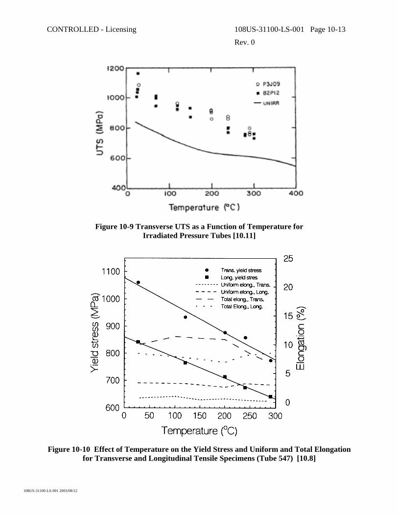
CONTROLLED - Licensing 108US-31100-LS-001 Page 10-13
Rev. 0
108US-31100-LS-001 2003/08/12
Figure 10-9 Transverse UTS as a Function of Temperature for Irradiated Pressure Tubes [10.11]
Figure 10-10 Effect of Temperature on the Yield Stress and Uniform and Total Elongation for Transverse and Longitudinal Tensile Specimens (Tube 547) [10.8]

CONTROLLED - Licensing 108US-31100-LS-001 Page 10-14
Rev. 0
108US-31100-LS-001 2003/08/12
0 1 2 3 4 5 0
100
200
300
400
500
600
700
¤
¤ ¤
¤
Crack extension (mm)
J-in
tegr
al (k
J/m
²) 200°C
100°C
30°C
300°C
Symbol denotes max. load
Metastablecrack growth
Sharp slope change
Figure 10-11 Typical J-Resistance Curves from Small Specimen Tests on Irradiated Material at Different Test Temperatures
0 2 4 6 8 10 12 0
50
100
150
200
250
300
Cl concentration (wt ppm)
J ml (
kJ/m
²)
< 100% recycled 100% recycled
Trend line
Figure 10-12 J at Maximum load, Jml, from Curved Compact Specimens of Irradiated Material Tested at 250°°°°C Versus Cl Concentration [10.9]

CONTROLLED - Licensing 108US-31100-LS-001 Page 10-15
Rev. 0
108US-31100-LS-001 2003/08/12
Figure 10-13 Hydride Morphology and Applied Stress for Zr-2.5Nb Material [10.21]

CONTROLLED - Licensing 108US-31100-LS-001 Page 10-16
Rev. 0
108US-31100-LS-001 2003/08/12
Figure 10-14 Fracture Toughness Versus Temperature for Unirradiated Zr-2.5Nb with Various Hydride Morphologies [10.19]

CONTROLLED - Licensing 108US-31100-LS-001 Page 10-17
Rev. 0
108US-31100-LS-001 2003/08/12
Figure 10-15 Effect of Test Temperature on the Crack Growth Toughness of Irradiated Zr-2.5Nb Pressure Tube Materials with High (P3J09) and Low (all others)
Cl Concentrations [10.11]
0 5 10 15 20 25 0
50
100
150
200
250
Fast-Neutron Fluence (1025 n/m²)
J ml (
J/m
²)
H737 Unirrad. material
H737 Irrad. mat., Tirr = 250-260°C
F316 Unirrad. material
F316 Irrad. mat., Tirr = 274-289°C
H850 Unirrad. material
H850 Irrad. mat., Tirr = 250-260°C
Initial transient
Cl < 0.2 wt ppm
Cl = 4 wt ppm
Initial transient
y = 55.2 - 0.55x
Trend line
All material with P < 10 wt. ppm. Tirr is the irradiation temperature in °C.
Figure 10-16 J at Maximum Load, Jml, from Curved Compact Specimens of Irradiated Material Tested at 240/250°°°°C Versus Fast Neutron Fluence [10.9]

CONTROLLED - Licensing 108US-31100-LS-001 Page 10-18
Rev. 0
108US-31100-LS-001 2003/08/12
Figure 10-17 Comparison of the Maximum-Pressure/Load Toughness Determined from Burst Tests and Curved Compact Specimens at 250°°°°C [10.15]
Figure 10-18 J at Maximum Pressure Toughness Based on Instantaneous Crack Size from Burst Tests on Irradiated Pressure Tubes with Various Cl Concentrations [10.9]

CONTROLLED - Licensing 108US-31100-LS-001 Page 11-1
Rev. 0
108US-31100-LS-001 2003/08/12
11. INSPECTION AND MONITORING OF CANDU FUEL CHANNELS
11.1 Inspection Programs
Inspection and monitoring of CANDU reactor fuel channels is performed to satisfy regulatory requirements (Periodic Inspection Program), or to provide information about known or suspected problems necessary to assist in maintenance and future component design (In-service Inspection Programs).
The Periodic Inspection Program (PIP) involves inspecting a relatively small sample of tubes in each reactor on a recurring basis, to ensure identification of any generic problems. The requirements for PIP are described in Canadian Standard CAN/CSA-N285.4 [11.1]; these are mandatory in Canada and have generally been adopted by all CANDU operators and regulators outside Canada. A summary of these requirements is given in Table 11-1. A revision of these requirements is expected to occur in the next issue of the standard, likely in 2004.
The second type of program, In-service Inspection (ISI), tends to be reactor-specific and is generally directed by reactor operators with concurrence of the regulatory authority. It aims to provide specific information about known or suspected problems. The objectives of ISI programs change as requirements for information evolve.
In order to satisfy these requirements, and also to minimize both outage time and radiation exposure to personnel, many techniques and inspection systems, some of them highly-automated and multifunctional, have been developed. Subsection 11.2 reviews the measurement techniques that are now available for the inspection and monitoring of fuel channel components; it also provides background information on events that prompted the need for these inspections. Subsection 11.3 briefly describes some of the multifunctional systems that have been developed to implement these methods.
11.2 Fuel Channel Inspection and Monitoring Methods
11.2.1 Summary
Fuel channel inspection and monitoring capabilities have developed progressively as needs were recognized. AECL instituted monitoring programs for the prototype NPD (Nuclear Power Demonstration) and Douglas Point reactors involving in-channel dimensional gauging and also tube removals. When Ontario Hydro’s1 first CANDU reactors at Pickering were commissioned, the periodic inspection program only required that the inside diameter, sag profile, length and surface profilometry of a small number of tubes be measured about every 5 years. The diameter, sag and length were required to confirm that the irradiation creep and growth of the pressure tube were in agreement with the equations used to define the design basis. Surface profilometry was used to ensure that the fuel bundle bearing pads were not unduly wearing or damaging the
1 Ontario Hydro is now known as Ontario Power Generation Inc or OPG

CONTROLLED - Licensing 108US-31100-LS-001 Page 11-2
Rev. 0
108US-31100-LS-001 2003/08/12
internal pressure tube surface. The equipment used for this inspection, known as the Dry Channel Inspection Equipment, is described in Subsection 11.3.1. Operating experience at Pickering and later reactors subsequently broadened the scope of inspection methods that were required. A summary of current inspection methods and systems that have been developed to meet these needs is presented in the following subsections.
11.2.2 Pressure Tube Flaw Detection and Characterization
11.2.2.1 Volumetric Inspection Methods
Prior to 1974, in-service volumetric inspection of pressure tubes (inspection of the full volume of the metal for flaws rather than just its surface) had not been anticipated. The tubes were volumetrically inspected during manufacture [11.2]; operating conditions were not expected to be conducive to flaw development; and there was no experience base for flaw initiation and growth. However, in 1974, leaks developed in some Pickering Unit 3 and 4 fuel channels. The cause was found to be cracks that had developed in the pressure tubes at the rolled joints due to improper installation procedures (Subsection 13.1.2). Leaking channels were located using acoustic emission techniques described in Subsection 11.2.6. However, a number of other channels had partial through-wall cracks that had to be located to prevent future problems. Rudimentary ultrasonic rolled joint inspection equipment was developed by AECL and Ontario Hydro to locate such flaws.
Bruce NGS A was also under construction at this time and pressure tubes had already been installed in Units 1 and 2 using similar procedures as those used for Pickering 3 and 4. Remedial measures (stress relieving of the rolled joints) were undertaken and a reinspection of the full length of the pressure tubes was performed using eddy current inspection techniques with Dry Channel Inspection Equipment developed by AECL. This equipment and its capabilities are discussed in Subsection 11.3.1. During the pre-service eddy current inspection of Bruce 1 and 2 tubes, a defect was discovered in one tube. Further investigation revealed that it was introduced during manufacture of the tube and had not been detected during manufacturing inspection. Changes were subsequently made to the tube manufacturing and inspection procedures to reduce the possibility of this type of flaw re-occurring (Subsection 6.2.1).
The development of rolled joint cracks and the discovery of a manufacturing flaw in a tube in- reactor, highlighted the need for an inspection system capable of performing volumetric flaw detection in addition to satisfying other periodic inspection requirements. The system had to operate quickly and minimize radiation exposure to operating personnel. To meet these needs, the CIGAR system (Channel Inspection and Gauging Apparatus for Reactors) was developed by Ontario Hydro. CIGAR was the first “wet” fuel channel inspection system; its inspection head was capable of operating submerged in heat transport coolant. Previous inspection systems were “dry”; they required freeze plugs on channel feeders – a time consuming and radiation intensive operation. CIGAR equipment and its capabilities [11.3] are discussed in Subsection 11.3.2. It came into service in 1985 and was the primary CANDU fuel channel inspection and gauging system in use for about 15 years. The CIGAR delivery machine, a complex automated system, was just entering its commissioning phase when the rupture of pressure tube G16 occurred at

CONTROLLED - Licensing 108US-31100-LS-001 Page 11-3
Rev. 0
108US-31100-LS-001 2003/08/12
Pickering Unit 2 in August 1983 (Subsection 13.1.1). CIGAR’s capabilities were required but attempting to use such a complex system untested in a radioactive environment was out of the question. A small manually installed delivery system was quickly developed by AECL that operated with the CIGAR inspection heads, drive rods and inspection instrumentation. The system, christened CIGARette [11.4], satisfied the immediate inspection need by using ultrasonic methods to determine that the conditions that had caused the failure of G16 were present in other fuel channels in both Pickering Units 1 and 2.
Another significant event precipitated further developments in volumetric inspection technology. In 1986, the pressure tube in Bruce Unit 2, Channel N06 started to leak, the unit was shutdown, but the tube later failed during low temperature pressurization. (Subsection 13.1.2). Investigation showed that the leak was caused by a crack that grew from a manufacturing defect (piping flaw) of similar origin to that mentioned earlier. Concern was raised about the possibility of other manufacturing defects being present in Bruce 1 and 2 and Pickering 3 and 4 pressure tubes. (Pickering 1 and 2 were being retubed and the tubes in later reactors had been subjected to improved manufacturing inspection).
From knowledge of the manufacturing process, these type of flaws are expected to occur only in certain tubes derived from the top of an ingot with a deeper than usual piping cavity, and likely only at one end of the tube, i.e., at a rolled joint region. Three separate programs were undertaken to address this manufacturing defect concern for older reactors:
• An in-service inspection program was established in Ontario Hydro reactors to perform full length volumetric inspection of all installed “top-of-ingot” pressure tubes using CIGAR ultrasonics.
• Special equipment was developed and a program established to inspect the offcuts (rings of pressure tube material cut off each end of every pressure tube when it is installed and kept in archives). This reinspection includes the use of a high frequency (100 MHz) ultrasonic method demonstrated to have better detection sensitivity to some manufacturing flaws than standard manufacturing inspection methods. Suspect tubes identified by this process became part of subsequent in-service inspection programs.
• It was decided that a specialized system was required to rapidly inspect only the rolled joint region of pressure tubes in Ontario Hydro’s older reactors. The CIGAR system can inspect only 1 or 2 channels/day. The new system, PIPE (Packaged Inspection Probe), was designed to inspect up to 24 rolled joints/day. PIPE was first used in Bruce Unit 2 in 1987; a brief description of the equipment and its capabilities is given in Subsection 11.3.5.
In 1998 AECL embarked on the development of a second generation, multi-functional, “wet” fuel channel inspection system primarily to service the increasing numbers of CANDU 6 reactors worldwide. This system includes full-scope volumetric inspection capabilities: two eddy current and six ultrasonic transducers. It is designated AFCIS (AECL Fuel Channel Inspection System) and is described in more detail in Subsection 11.3.3. Figure 11-1 shows typical ultrasonic response from calibration artifacts in a section of pressure tube.

CONTROLLED - Licensing 108US-31100-LS-001 Page 11-4
Rev. 0
108US-31100-LS-001 2003/08/12
11.2.2.2 Surface Flaw Characterization
By far the most prevalent flaws encountered in in-service CANDU pressure tubes are various types of mechanical damage to internal pressure tube surfaces. In addition to the ultrasonic and eddy current capabilities described in the previous subsection, a number of other inspection techniques have been developed to detect and characterize surface flaws.
The Dry Channel Inspection Equipment initially used for periodic inspection of pressure tubes, prior to the introduction of the CIGAR system, had a strain gauge stylus type surface profilometer. Its primary function was monitoring the extent and depth of any fuel bundle damage on the bottom of pressure tubes. By the time CIGAR was being developed, it had been concluded that fuel damage was not a generic problem and that monitoring of any surface damage could be carried out by eddy current methods if required. Later, concern arose about possible fretting of some pressure tubes in two Pickering B units and all Ontario Hydro’s “thirteen-bundle reactors” (Bruce A&B and Darlington). A number of prototype surface profiling approaches were initially developed to address these concerns. However, the following methods have evolved as most suitable for detecting and characterizing damage to pressure tube internal surfaces:
• Tightly-focused, high-frequency ultrasonic (UT) normal beam probes provide accurate depth information. Figure 11-2 shows an example.
• Eddy current testing (ET) provides valuable information to complement ultrasonic results.
• Visual examination using radiation resistant CCTV (Closed Circuit Television).
• Significant flaws are normally examined by flaw replication using a dental molding compound. Replicas are recovered and detailed flaw geometry is obtained using laser profilometry on the replica. Figure 11-3 shows a replica of a debris flaw and typical laser profilometry results.
All of these techniques can be implemented in “wet” (flooded) channels. They are normally employed progressively. Flaws that are reportable but clearly not requiring disposition are generally only examined using UT and ET (if available). Since there is both a radiation dose and time penalty associated with visual examination and replication of flaws, these techniques are usually only implemented on flaws that are, or may be, difficult to disposition. Replication is the most “expensive” test method; however, it can provide detailed flaw geometry information such as root-tip-radius.
11.2.3 Monitoring Pressure Tube Geometry
Changes in fuel channel geometry are monitored to verify that the results of processes discussed in Section 8 remain within predicted limits.

CONTROLLED - Licensing 108US-31100-LS-001 Page 11-5
Rev. 0
108US-31100-LS-001 2003/08/12
11.2.3.1 Diameter and Wall Thickness Measurement
The periodic monitoring of pressure tube diameter is important to assure that diametral creep and growth remain within the limits defined in the design. From the early 1970s, pressure tube diameter gauging was performed using a Linear Variable Differential Transformer (LVDT) measurement device on the Dry Channel Inspection Equipment. The CIGAR inspection system, commissioned in 1985, uses an ultrasonic gauging system that measures wall thickness as well as diameter at 60 positions around the tube at 3 mm axial intervals along its length. More recently, AFCIS relies on waterproof LVDT technology to monitor diameter and uses ultrasonics to measure wall thickness; both measurements involve 360 readings around the tube at about 1 mm axial intervals.
11.2.3.2 Sag Measurement
Measurement of the pressure tube displacement profile and the maximum vertical deflection (sag) are a code periodic inspection requirement. The original Dry Channel Inspection Equipment measured the local curvature at many positions along the tube using an LVDT device to measure deviation from a defined straight line. Displacement and maximum sag were calculated by double integration of this data. CIGAR uses a servo-inclinometer to measure the slope at many positions along the tube and calculates the displacement profile from a single integration. AFCIS has returned to the use of an LVDT device to determine channel sag.
11.2.3.3 Pressure Tube Elongation
It is not pressure tube length but a related quantity – position on end-fitting bearings – that is the primary reason for measuring tube elongation. Secondary factors include: possible interference between feeders for channels elongating at different rates and scheduling of “channel shift” operations (for Bruce-type reactors) to ensure channels will remain on-bearing.
Multifunctional inspection systems typically can provide pressure tube length measurements from their delivery machine axial travel sensors. The Dry Channel Inspection Equipment and AFCIS provide the length between rolled joint burnish marks to a typical measurement accuracy of a few mm. A number of methods have been developed over the years for situations where length, or position-on-bearing, is required for large numbers of channels. They range from basically manual surveying type methods to remotely operated methods that can be implemented off or on-power. Two of the latter approaches are in general use today:
• For reactors with dedicated fuelling machines (FM) like CANDU-6, total channel length is generally derived from FM “Z-travel”, perpendicular to the reactor face. It provides length information each time a channel is refueled. Over time, it produces a detailed data base for channel elongation. Figure 11-4 shows an example of this type of elongation data.
Ontario Hydro developed an end-fitting displacement measurement device that is attached to the front of a fuelling machine. It measures the distance from the end fittings to the FM snout as the machine travels along a row of end fittings. By this means an entire reactor face can be scanned rapidly and remotely.

CONTROLLED - Licensing 108US-31100-LS-001 Page 11-6
Rev. 0
108US-31100-LS-001 2003/08/12
11.2.4 Structural and Material Changes
11.2.4.1 Spacers
Shortly after the failure of Pickering Unit 2 pressure tube G16, the cause was determined (Subsection 13.1.1). “Garter spring” spacers that separate the hot pressure tube from the cooler calandria tube were not in their design locations allowing the two tubes to come into contact. High hydrogen in the Zircaloy-2 tube had led to the formation of hydride blisters at the contact location. Cracks formed in the growing blisters and these eventually led to the failure.
Prior to the failure of G16, the need to determine spacer location had not been considered essential. AECL designed a transmit-receive eddy current probe that became the standard on all inspection systems for detection/location of “loose” spacers in in-service reactors. It has also been used on reactors with “snug” spacers for final installation checks.
Unfortunately, eddy current methods are not effective on current snug-design spacers after reactor start up; surface oxidation of the spacer girdle wire eliminates the continuous electrical path around the spacer and makes eddy current methods ineffective. However, alternate ways have been found to locate snug spacers in-service. Ultrasonic response, bottom-of-channel curvature, and diameter data have all provided evidence for snug spacers. The single most successful method currently available involves processing the detailed internal diameter data (Subsection 11.2.3.1) to amplify the small, localized geometry variations in the pressure tube where it rests on a spacer; Figure 11-5 shows an example.
11.2.4.2 Pressure Tube to Calandria Tube Contact
The spacer location coils and CIGAR ultrasonic flaw detection system were the primary inspection tools used during the inspection of Pickering 1 and 2 after the G16 failure. When a spacer was found to be significantly out of position, ultrasonic inspection usually detected a response from the bottom of the tube midway between the spacers. Cracks in individual hydride blisters produced fairly high amplitude response. Patches of lower amplitude response around and between blisters were shown to coincide with surface roughness and white oxide in the contact zone.
Inspections performed in other reactors with “loose” design spacers (all of which have pressure tubes made of a newer alloy, Zirconium-2.5% Niobium (Zr-2.5Nb) have located some fuel channels with spacers significantly displaced from their design location. In these cases, only low amplitude ultrasonic indications, interpreted as roughness and oxide, have been observed on the outside surface at the expected contact location. Some of these tubes were removed and metallography confirmed that no hydride blisters were present.
CANDU reactors with loose spacers have been, or are being, reconfigured to remove all cases of pressure tube to calandria tube contact prior to the pressure tubes reaching their blister formation threshold. For such channels ultrasonic evidence of contact may merely mean that the channel was in contact at some time in the past – it is not firm evidence of present contact.

CONTROLLED - Licensing 108US-31100-LS-001 Page 11-7
Rev. 0
108US-31100-LS-001 2003/08/12
11.2.4.3 Pressure Tube to Calandria Tube Gap
Determination of pressure tube to calandria tube gap is now a code requirement. CAN/CSA-N285.4 permits gap determination by two different methods: (a) direct measurement of gap variations along the channel or (b) calculation of gap based on measured spacer locations and sag.
CIGAR does not include a direct gap measurement capability; it relies on method (b). AFCIS includes a transmit-receive eddy current method for direct gap measurement; results need to be compensated for local variations in pressure tube wall thickness – this is accomplished using the ultrasonic wall thickness values obtained during dimensional gauging (Subsection 11.2.3.1). Figure 11-6 shows a typical bottom-of-channel gap profile after about 30,000 hours of reactor operation.
11.2.4.4 Hydrogen Measurement
The formation of hydride blisters at the contact region between a pressure tube and calandria tube requires a high level of hydrogen (or its isotopes) in the tube. At present, the only available and proven “non-destructive” method of determining the amount of hydrogen in a pressure tube is to remove a sample of tube material and analyze it. Sampling tools were developed by AECL that first remove the surface oxide layer and then machine a 0.1 mm thick sliver of clean material from a small area of the pressure tube. The original sampling tools were “dry”. They required the fuel channel to be inspected to be defueled, isolated by freeze plugs in the feeders, drained and swabbed before the samples were taken. This was a fairly lengthy process involving radiation exposure to personnel.
Sampling tool design has evolved to overcome these shortcomings. “Wet” tools now exist that are delivered and operated by fuelling machines [11.5]. The most recent advance in sampling tool design includes four sets of cutters in a single multi-sampling tool. It can obtain samples from four different axial locations in a pressure tube during a single channel entry. Previously it required insertion of four separate tools to recover the required number of samples. This tool, delivered by the AFCIS delivery machine can provide four samples from a channel in a few hours. Figure 11-7 shows a photograph of the tool.
11.2.4.5 Material Surveillance
Although it cannot be achieved non-destructively, there is a code requirement for monitoring the key pressure tube physical properties of fracture roughness and delayed hydride cracking velocity. These involve pressure tube removal and hence this requirement only applies to the CANDU lead unit with a particular type of pressure tube alloy. (Most CANDU reactors presently operating contain cold-worked Zr-2.5Nb pressure tubes.)

CONTROLLED - Licensing 108US-31100-LS-001 Page 11-8
Rev. 0
108US-31100-LS-001 2003/08/12
11.2.5 Calandria Tube Geometry
11.2.5.1 Calandria Tube Dimensional Gauging and Inspection
Calandria tubes are largely inaccessible except when a pressure tube is being removed. There are no mandatory requirements to inspect or gauge calandria tubes. However, it is desirable to perform measurements when opportunities arise to ensure that unexpected changes are not occurring. To allow this, calandria tube gauging, profilometry and curvature measurement heads have been developed to operate with the Dry Channel Inspection Equipment described in Subsection 11.3.1. The inspection head designs are based on those for pressure tubes but modified to accommodate the larger calandria tube diameter. This allows measurements of the tube’s overall length, diameter and ovality; sag profile and maximum displacement; and surface condition at garter spring, contact and other locations. Tooling also exists for CCTV visual examination of the internal calandria tube surface.
11.2.5.2 Calandria Tube Elongation
Measurement of increased pressure tube elongation led to some early concerns that calandria tubes might also increase in length. The ends of the calandria tubes are rolled into the end-shields of the calandria vessel; it is not possible to routinely measure the elongation of individual calandria tubes in the reactor.
Collectively, the elongation of all calandria tubes could cause the reactor end-shields to be pushed apart. Although reactor design allows for some change due to factors like thermal expansion, pressure and radiation induced growth, unexpected amounts due to elongation might cause future problems. Hence, several methods were developed for monitoring the separation of end-shields with time. The first method used custom built tools, optical tooling and laser distance measuring equipment to survey a traverse around the reactor and measure the absolute separation of the end-shields. Measurements were made on Pickering Unit 1 in 1975 and again in 1977. The results were somewhat inconclusive; if calandria tube elongation were occurring, the rate would be less than could be reliably measured by this method.
Another method was developed to measure end-shield separation that used a calibrated Invar tape to determine the overall length of a drained defueled channel through its bore and spotface tools to measure the distance from the ends of the end fittings back to the end-shields. This method had limited use because of the high economic and radiation exposure costs associated with freezing and draining channels.
The last method employed radiation resistant measuring devices that were permanently mounted between the reactor vault floor and end-shield cooling pipes attached to the bottom of the end-shields. These devices were installed in Pickering Units 1 and 3 in 1982. Measurements could be made from outside the reactor vault both during shutdown and full power operation. Periodic monitoring of these devices over a 4-year period did not identify changes that could be attributed to calandria tube elongation.

CONTROLLED - Licensing 108US-31100-LS-001 Page 11-9
Rev. 0
108US-31100-LS-001 2003/08/12
In the intervening period, AECL carried out accelerated specimen tests that indicate that calandria tube elongation rates will not be higher than assumed during original reactor design (Section 8).
11.2.6 Leak Location
A CANDU reactor’s heat transport system consists of a large number of separate pressure boundary components; up to 480 fuel channels each with inlet and outlet feeder pipe connections and closure plugs for on power refueling. Also, there are heavy water moderator and various light water cooling systems within the reactor that could possibly develop leaks. Despite the apparent potential, careful design, construction, operation and maintenance of these reactors has resulted in very few leaks occurring. However, it is important to be able to detect a leak if it occurs and to quickly identify the location of a leak.
Leak detection systems are designed into the reactor. The annulus gas (carbon dioxide) flows through each fuel channel between the pressure tube and the calandria tube. The dew point of this gas is constantly monitored during reactor operation. Also, air from the reactor vaults is circulated through driers and the collection rate is carefully monitored. An increase in annulus gas system dew point or dryer collection rate indicates that a leak exists. Analysis of the isotopic content of the collected water identifies which system is leaking.
To date, all fuel channel leaks have been associated with the high pressure heat transport system and have been due to either feeder pipe connection leaks, closure plug leaks or through-wall cracks that have occurred at pressure tube rolled joints due to improper installation or maintenance procedures.
The annulus gas leak detection system, in current reactors, typically includes “strings” of 11 channels. A leak in any one of these channels provides an alarm but no indication which of the eleven channels is leaking.
To locate the specific fuel channel component that is leaking, an acoustic emission (AE) system was developed by Ontario Hydro [11.6]. It consists of instrumentation located outside containment connected via cables and preamplifiers to a sensor head mounted on the front of a fuelling machine. The sensor head consists of a round metal plate to which is attached a low frequency ultrasonic leak detection horn and one or more piezoelectric AE transducers sensitive to different frequency ranges. The round plate is acoustically isolated from the fuelling machine.
Location of the instrumentation outside containment allows the equipment to be used either during shutdown or on-power operation. During use, the device can be moved about in front of the fuel channels by traversing the fuelling machine. In this mode, the low frequency ultrasonic leak detector senses airborne noise from closure plug leaks or local areas of higher than average airborne noise from feeder pipe leaks. A second mode of operation requires the fuelling machine to press the sensing plate hard against the end of a fuel channel end fitting. This allows higher frequency acoustic activity from leaks remote from the sensors, for example at the feeder connection or at the pressure tube rolled joint to be detected. The acoustic frequency spectra of a leak usually distinguishes it from other sources within the reactor. Experience has shown that

CONTROLLED - Licensing 108US-31100-LS-001 Page 11-10
Rev. 0
108US-31100-LS-001 2003/08/12
feeder connection leaks > 1.0 kg/h and pressure tube leaks > 0.5 kg/h can be located with this system.
For leak rates less than 0.5 kg/h a number of other methods have been used to narrow down the number of potential leak sites or channels. They include ultrasonic monitoring for water in the “pig-tails” connecting channels in an annulus gas “string” and careful monitoring of channel outlet temperature. These methods help narrow down leak locations but may not always be sufficient by themselves to isolate a leak to a single channel. Volumetric inspection of a few remaining suspect channels may eventually be the only source of conclusive proof.
11.3 Multifunctional Fuel Channel Inspection Systems
11.3.1 Dry Channel Inspection Equipment
Dry Channel Inspection Equipment was originally developed at AECL’s Chalk River Laboratories (AECL-CRL) and Orenda Ltd., to monitor behavior of experimental pressure tubes and tubes in prototype reactors. A system was purchased by Ontario Hydro for periodic pressure tube monitoring at Pickering NGS A in the early 1970s. It was capable of measuring:
i) The local curvature along the tube from which the sag profile of the tube can be calculated. In some cases, the location of garter spring spacers can also be deduced from curvature information.
ii) The tube minimum and maximum inside diameter at 12.7 mm intervals along the tube length.
iii) Profilometry of the tube inside surface from which the depth and extent of surface damage can be determined.
The use of this equipment requires time consuming reactor face procedures during which operating personnel can be exposed to radiation.
In the early 1980s the Ontario Hydro and AECL dry inspection systems started to diverge in terms of the delivery machine although the basic inspection technology remained the same. About this time an eddy current flaw detection capability was added to both systems to satisfy new code requirements introduced at that time. The Ontario Hydro dry system was replaced by CIGAR in 1985. The AECL system continued to be used on: thousands of pre-service pressure tubes [11.7], experimental pressure tubes, tubes removed from reactors, and a few offshore inspection campaigns. The current AECL dry system includes capabilities for ultrasonic and eddy current volumetric inspection, wall thickness, pressure/calandria tube gap measurement, loose spacers, and video examination in addition to the original tests for curvature (gap), diameter, and surface profilometry. The AECL dry system has recently been upgraded to replace obsolete control and data acquisition equipment/software.
11.3.2 CIGAR
CIGAR (Channel Inspection and Gauging Apparatus for Reactors) was developed by Ontario Hydro in recognition of the need for a system capable of performing a range of measurements on

CONTROLLED - Licensing 108US-31100-LS-001 Page 11-11
Rev. 0
108US-31100-LS-001 2003/08/12
any of its reactors quickly and with minimum radiation exposure to its operators [11.3]. CIGAR was the first “wet” inspection system; its inspection head is designed to operate while submerged in heat transport coolant – in fact it relies for this water to couple UT beams into the pressure tube. The system has been operational since 1985 and has inspected hundreds of channels in Ontario Hydro’s reactors as well as CANDU 6 reactors at Gentilly-2, Pt. Lepreau and Korea’s Wolsong-1. CIGAR is capable of the following with its primary inspection head: i) Flaw Detection - Ultrasonic volumetric inspection of the pressure tube using four
45° shearwave transducers, arranged as circumferential and axial pairs, and one normal beam transducer.
ii) Diameter Measurement - Ultrasonic gauging of the pressure tube inside diameter is performed at 18 degree intervals around the circumference at approximately 2000 axial positions along the tube. Tables and graphs of minimum and maximum diameter, their orientations and tube ovality can be obtained.
iii) Wall Thickness – Ultrasonic gauging of pressure tube wall thickness is performed at the same time as diameter gauging and similar outputs are available.
iv) Sag Measurement – The sag profile of the pressure tube is calculated from servo-inclinometer average slope measurements made at 30 mm intervals along the tube.
v) Spacer Location – The axial position of the “garter spring” spacers are located using transmit-differential-receive eddy current coils.
In addition, there are special purpose CIGAR inspection heads that can be used for specific applications:
a) Inside Surface Profilometry - A stylus profilometer for measuring the depth of inside surface imperfections such as fuelling scratches, fuel bundle fret marks or fretting due to debris exists. It requires a dedicated inspection head configuration and is used only to satisfy special inspection requirements.
b) Flaw replication can be performed.
c) CCTV Video Inspection Head - A dedicated inspection head containing an underwater television camera and associated lighting has been developed to interface with the CIGAR drive unit to provide visual inspection capability.
CIGAR is capable of inspecting about one fuel channel per day at almost 100% volumetric inspection coverage. Installation of the drive mechanism on the fuelling machine bridge and maintenance of equipment require minimal radiation exposure of personnel.
11.3.3 AFCIS
The AECL Fuel Channel Inspection System (AFCIS) was developed by AECL in 1998. It was commissioned in 1999 and has been used in eight inspection campaigns at six different offshore CANDU 6 reactors over the past four years; two more inspections are scheduled for 2004. AFCIS is the first second-generation “wet” inspection system [11.8]. One of its key features is an independently rotating inspection module that enables 100% coverage of a full length

CONTROLLED - Licensing 108US-31100-LS-001 Page 11-12
Rev. 0
108US-31100-LS-001 2003/08/12
pressure tube in about 2 hours at 0.9 mm pitch. This feature represents an improvement in spiral scan inspection speed of at least a factor of five over earlier inspection systems. AFCIS is capable of the following:
i) Ultrasonic volumetric inspection using: four 45° shear wave transducers arranged in circumferential and axial pairs, a radially aimed 10 MHz normal beam transducer, and a high-frequency, 20 MHz, normal beam transducer for profiling internal tube surfaces. Figure 11-1 shows the response from one of the 45° transducers.
ii) Eddy current volumetric inspection to complement [11.9] the ultrasonic inspection results for flaws on or near internal surfaces.
iii) Measurement of pressure tube diameter using an LVDT based probe (Figure 11-8). iv) Measuring pressure tube wall thickness using ultrasonics (Figure 11-9). v) Determination of local pressure tube curvature using LVDT transducers; channel deflection
(sag) can be calculated from curvature (Figure 11-10). vi) Direct measurement of pressure-to-calandria tube gap using a transmit-receive eddy current
method combined with ultrasonic pressure tube wall thickness compensation (Figure 11-6). vii) Location of “loose” garter spring spacers using an improved dual channel transmit-receive
eddy current probe [11.10]. The above capabilities are included on the primary AFCIS inspection head. In addition there are two special purpose inspection heads that are used on an as-required basis. One provides video examination and flaw replication. The second is a multi-sampling tool for collecting samples from the internal pressure tube surface for hydrogen analysis; this head can collect samples from four different axial locations during a single channel entry (Subsection 11.2.4.4).
AFCIS is capable of inspecting two channels per day at 100% volumetric inspection coverage.
11.3.4 ANDE
An Advanced Non-Destructive Evaluation system is currently under development by OPG. It is intended to replace CIGAR. It will have an integral rotating inspection module permitting considerably faster (100%) channel coverage than is possible with CIGAR. ANDE is also believed to have considerably more sensors on its inspection head although full details have not yet been released. ANDE is designed to be delivered by a Universal Delivery Machine (UDM). Each OPG station will require a dedicated UDM.
11.3.5 Special Purpose Inspection Systems
Unique situations at some reactors have occasionally produced inspection requirements beyond the capabilities of existing equipment. Faster inspection speed is often the key requirement. These situations produced a number of rapid-response capabilities that were used to provide the essential information as quickly as possible. The equipment was rarely maintained in useable condition after its primary function had been satisfied because in most cases enhanced speed was achieved through significant specialization. The equipment was generally not capable of satisfying all the requirements of the more routine, full-scope inspections necessary to satisfy code, operational, and regulatory concerns. Also, some can only be implemented at the cost of

CONTROLLED - Licensing 108US-31100-LS-001 Page 11-13
Rev. 0
108US-31100-LS-001 2003/08/12
extended reactor outages. However, the basic design and operational experience for these specialized systems exist and could be called on to address urgent needs. For completeness, a brief description of these systems follows.
• CIGARette was developed by Ontario Hydro [11.4] and AECL in 1983. It combined a CIGAR inspection head with a manually mounted friction drive attached to end fittings. It was not capable of continuous head rotation but provided essential pressure tube condition information following the rupture of a Zircaloy-2 pressure tube in Pickering-2 (Subsection 13.1.1).
• PIPE (Packaged Inspection Probe) was designed by Ontario Hydro in 1987 for rapid ultrasonic inspection of many rolled joints. It used a modified fuelling machine to deliver four 45° shear wave transducers. It was used at Bruce-2 and achieved inspection of 20 rolled joints per day.
• BLIP (Blister and Spacer Location Inspection with PIPE) was developed by Ontario Hydro in 1988. It performed spacer location and rapid ultrasonic inspection of the bottom of a pressure tube for hydride blisters. BLIP was delivered by a modified fuelling machine – similar to PIPE. It was used in 1990 to inspect 300 channels in Pickering-4.
• SLAR (Spacer Location and Repositioning) systems are used to relocate “loose” spacers in older CANDU reactors [11.11]. They are not actually inspection systems but include several inspection functions [11.12, 11.13] that are critical to successful SLAR operations. These include eddy current spacer location probes, fast-scan ultrasonics for hydride blister detection, and combined eddy current/ultrasonics for pressure-to-calandria tube gap determination. SLAR tools have been used in several thousand CANDU fuel channels using a variety of delivery machines.
11.4 Fuel Channel Inspection in ACR
The geometry and materials for ACR fuel channels will not differ significantly from those in current CANDU reactors. Also, similar periodic inspection requirements are expected for ACR as already exist for currently operating reactors. The basic inspection technology now in place for CANDU fuel channels is expected to be capable of satisfying all ACR requirements. Relatively minor modifications will have to be implemented to cope with the increased pressure tube wall thickness and changes in end-fitting geometry.
11.5 Summary
A wide variety of techniques and equipment have been developed and successfully used over the past 25 years to address periodic and in-service inspection requirements for fuel channels in CANDU reactors. This experience base was drawn on extensively in the recent development of two, second generation, multi-functional inspection systems, AFCIS and ANDE. Existing knowledge and techniques are expected to be sufficient to cope with anticipated and any unanticipated ACR fuel channel inspection requirements.
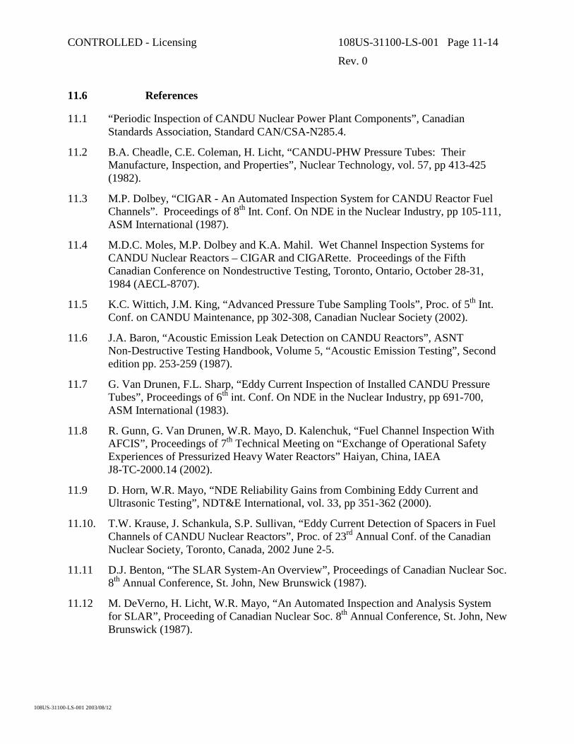
CONTROLLED - Licensing 108US-31100-LS-001 Page 11-14
Rev. 0
108US-31100-LS-001 2003/08/12
11.6 References
11.1 “Periodic Inspection of CANDU Nuclear Power Plant Components”, Canadian Standards Association, Standard CAN/CSA-N285.4.
11.2 B.A. Cheadle, C.E. Coleman, H. Licht, “CANDU-PHW Pressure Tubes: Their Manufacture, Inspection, and Properties”, Nuclear Technology, vol. 57, pp 413-425 (1982).
11.3 M.P. Dolbey, “CIGAR - An Automated Inspection System for CANDU Reactor Fuel Channels”. Proceedings of 8th Int. Conf. On NDE in the Nuclear Industry, pp 105-111, ASM International (1987).
11.4 M.D.C. Moles, M.P. Dolbey and K.A. Mahil. Wet Channel Inspection Systems for CANDU Nuclear Reactors – CIGAR and CIGARette. Proceedings of the Fifth Canadian Conference on Nondestructive Testing, Toronto, Ontario, October 28-31, 1984 (AECL-8707).
11.5 K.C. Wittich, J.M. King, “Advanced Pressure Tube Sampling Tools”, Proc. of 5th Int. Conf. on CANDU Maintenance, pp 302-308, Canadian Nuclear Society (2002).
11.6 J.A. Baron, “Acoustic Emission Leak Detection on CANDU Reactors”, ASNT Non-Destructive Testing Handbook, Volume 5, “Acoustic Emission Testing”, Second edition pp. 253-259 (1987).
11.7 G. Van Drunen, F.L. Sharp, “Eddy Current Inspection of Installed CANDU Pressure Tubes”, Proceedings of 6th int. Conf. On NDE in the Nuclear Industry, pp 691-700, ASM International (1983).
11.8 R. Gunn, G. Van Drunen, W.R. Mayo, D. Kalenchuk, “Fuel Channel Inspection With AFCIS”, Proceedings of 7th Technical Meeting on “Exchange of Operational Safety Experiences of Pressurized Heavy Water Reactors” Haiyan, China, IAEA J8-TC-2000.14 (2002).
11.9 D. Horn, W.R. Mayo, “NDE Reliability Gains from Combining Eddy Current and Ultrasonic Testing”, NDT&E International, vol. 33, pp 351-362 (2000).
11.10. T.W. Krause, J. Schankula, S.P. Sullivan, “Eddy Current Detection of Spacers in Fuel Channels of CANDU Nuclear Reactors”, Proc. of 23rd Annual Conf. of the Canadian Nuclear Society, Toronto, Canada, 2002 June 2-5.
11.11 D.J. Benton, “The SLAR System-An Overview”, Proceedings of Canadian Nuclear Soc. 8th Annual Conference, St. John, New Brunswick (1987).
11.12 M. DeVerno, H. Licht, W.R. Mayo, “An Automated Inspection and Analysis System for SLAR”, Proceeding of Canadian Nuclear Soc. 8th Annual Conference, St. John, New Brunswick (1987).

CONTROLLED - Licensing 108US-31100-LS-001 Page 11-15
Rev. 0
108US-31100-LS-001 2003/08/12
11.13 M.D.C. Moles, and D.W. Donnelly, “Ultrasonic Fast-Scan Blister Detection System”, Proceedings of Canadian Nuclear Society 8th Annual Conference, St. John, New Brunswick (1987).

CONTROLLED - Licensing 108US-31100-LS-001 Page 11-16
Rev. 0
108US-31100-LS-001 2003/08/12
Table 11-1 Summary of Minimum Code* Inspection Requirements for CANDU Fuel Channels
Baseline (Inaugural) Inspection- 10 High-Power and 2 Low-Power Channels
Periodic Inspection- 4 High-Power and 1 Low-Power Channel
Baseline (Inaugural) Inspection- In first 2 years of service
Periodic Inspection (ASME In-service Inspection)- First periodic inspection between 4 and 7 years after start-up- Subsequent inspections no more than 6 years apart.
Measurement: Integrity Concern:- Volumetric Inspection - Service-Induced Flaws- Pressure Tube Diameter - Flow Bypass- Pressure Tube Wall Thickness - Corrosion, Wear, and Deformation Thinning- Pressure Tube Length - Remaining Bearing Travel- Channel Deflection (Sag) - Fuel Passage
- Reactivity Mechanism Interference- Pressure/Calandria Tube Gap - Hydride Blister Formation- Garter Spring Spacer Location - Hydride Blister Formation- Hydrogen Isotope Concentration - Hydride Blister Formation
Volumetric Inspection:- No crack-like flaw indications- No flaws deeper in radial extent than 0.15 mm
Dimensional/Structural Inspection:- Diameter and wall thickness remain within design limits- Fuel Channel remains on bearings- No pressure/calandria tube contact
Hydrogen Isotope Concentration:- Acceptance criteria to be approved by regulator
CAN/CSA-N285.4, Clause 12,"Fuel Channel Pressure Tubes - Supplementary Inspection"
OBJECTIVETo ensure that no unacceptable degradation in component integrity is occurringand that the probability of failure remains acceptably low for the life of the plant.
ACCEPT/REJECT CRITERIA
INSPECTION SCOPE
INSPECTION INTERVAL
INSPECTION SAMPLE SIZE
* Based on the 1994 revision of the standard. Significant changes are expected for the next
revision (2004) in areas like sample size.
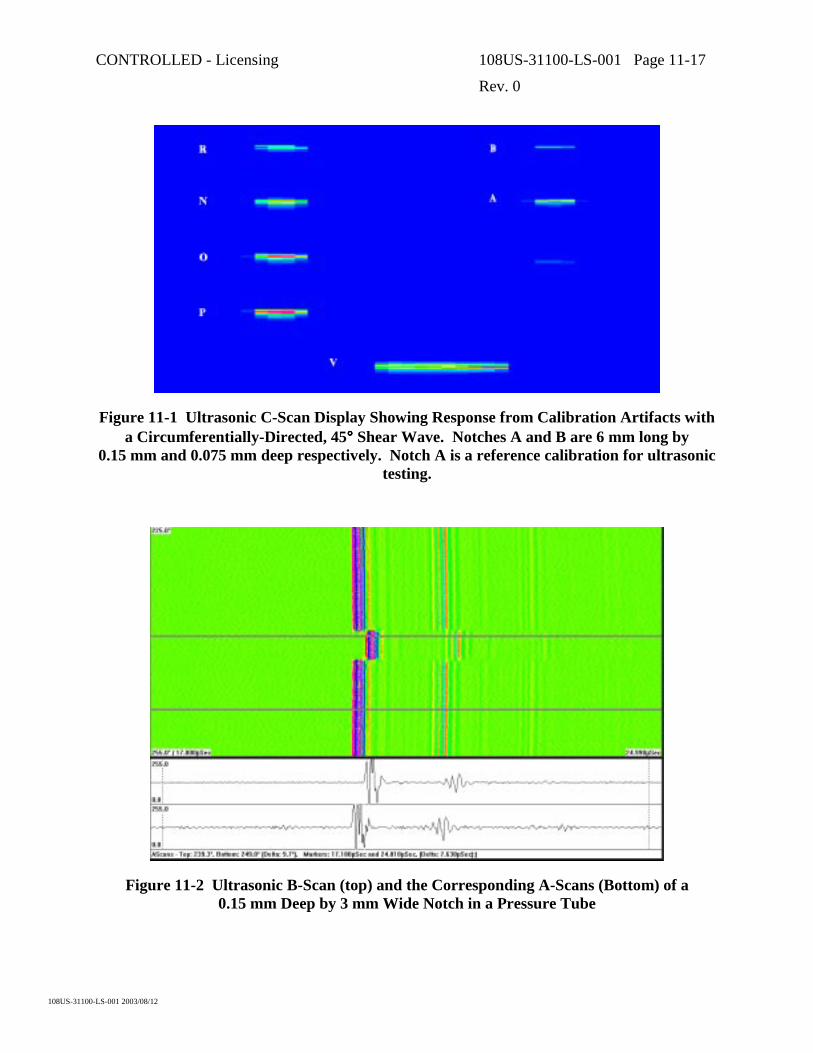
CONTROLLED - Licensing 108US-31100-LS-001 Page 11-17
Rev. 0
108US-31100-LS-001 2003/08/12
Figure 11-1 Ultrasonic C-Scan Display Showing Response from Calibration Artifacts with a Circumferentially-Directed, 45°°°° Shear Wave. Notches A and B are 6 mm long by
0.15 mm and 0.075 mm deep respectively. Notch A is a reference calibration for ultrasonic testing.
Figure 11-2 Ultrasonic B-Scan (top) and the Corresponding A-Scans (Bottom) of a 0.15 mm Deep by 3 mm Wide Notch in a Pressure Tube

CONTROLLED - Licensing 108US-31100-LS-001 Page 11-18
Rev. 0
108US-31100-LS-001 2003/08/12
(a)
(b)
(c)
200
250
300
350
400
450
500
550
600
650
700
0 500 1000 1500 2000 2500 3000 3500 4000 4500 5000Circumferential Distance (microns)
Rad
ial D
ista
nce
(mic
rons
)
200
250
300
350
400
450
500
550
600
650
700
0 500 1000 1500 2000 2500 3000 3500 4000 4500 5000Circumferential Distance (microns)
Rad
ial D
ista
nce
(mic
rons
)
Figure 11-3 (a) Macrophoto of a replica of a debris flaw. The horizontal marks are fuelling tracks – they are slightly curved due to replica distortion. The flaw is about 6 mm
long. The small circular objects are artifacts from debris or bubbles in the replicating compound. (b) Laser profile across (top to bottom) wide portion of flaw in (a). (c) Laser
profile across narrow portion of flaw in (a).

CONTROLLED - Licensing 108US-31100-LS-001 Page 11-19
Rev. 0
108US-31100-LS-001 2003/08/12
0
10
20
30
40
0 10 20 30 40 50
EFPH x 1000
Fuel
Cha
nnel
Elo
ngat
ion
(mm
)
Figure 11-4 Elongation Measurements for a Few Channels Derived from Fuelling Machine “Z-Travel” as a Function of Effective Full Power Hours
Figure 11-5 Plot of Processed Diameter Data Versus Distance from Channel E-Face Used to Locate Snug Garter Spring Spacers

CONTROLLED - Licensing 108US-31100-LS-001 Page 11-20
Rev. 0
108US-31100-LS-001 2003/08/12
0
2
4
6
8
10
2000 4000 6000 8000
Distance from A-Face (mm)
Gap
(mm
)
Figure 11-6 Pressure-To-Calandria Tube Gap Profile over the Length of a Fuel Channel. Vertical lines indicate confirmed spacer locations.
Figure 11-7 The AECL Multi-Head Sampling Tool Showing the Four Sampling Heads in the Main Module at the End of the Tool. The module to the left houses the actuator,
control mechanisms and connectors.

CONTROLLED - Licensing 108US-31100-LS-001 Page 11-21
Rev. 0
108US-31100-LS-001 2003/08/12
103.5
104.0
104.5
105.0
105.5
106.0
106.5
107.0
107.5
2000 3000 4000 5000 6000 7000 8000 9000
Distance from E Face (mm)
Insi
de D
iam
eter
(mm
)
.
Max. avg. diameter = 106.0 @ 4080 mm
Max.Avg.Min.
Figure 11-8 Diameter Profiles along a Pressure Tube that has Operated for about 100,000 Hours
3.5
4.0
4.5
5.0
2000 3000 4000 5000 6000 7000 8000 9000Distance from E Face (mm)
Wal
l Thi
ckne
ss (m
m)
Min. wall = 4.10 @ 4590 mm
Max.Avg.Min.
Figure 11-9 Typical Pressure Tube Wall Thickness Profile along a Channel after about 100,000 Hours of Operation

CONTROLLED - Licensing 108US-31100-LS-001 Page 11-22
Rev. 0
108US-31100-LS-001 2003/08/12
-40
-30
-20
-10
0
10
20
30
40
2000 3000 4000 5000 6000 7000 8000 9000
Distance from E Face (mm)
Cur
vatu
re (E
-6 m
m-1
)
-50
-40
-30
-20
-10
0
10
20
30
40
50
Def
lect
ion
(mm
)
Max. sag = 44 @ 5520 mm
Avg. Curvature
Figure 11-10 Average Curvature and the Derived Sag Profile of a Fuel Channel after about 100,000 Hours of Reactor Operation

CONTROLLED - Licensing 108US-31100-LS-001 Page 12-1
Rev. 0
108US-31100-LS-001 2003/08/12
12. APPLICATION OF LEAK BEFORE-BREAK PRINCIPLES TO THE PRESSURE TUBES OF CANDU REACTORS
12.1 Introduction
Although pressure tube rupture is an assumed accident for the purposes of licensing and the design of safety systems, avoidance of rupture is a key objective of fuel channel and interfacing system design. For CANDU, such rupture avoidance is based upon a number of factors related to design, pressure tube manufacturing standards, assembly requirements, operating and maintenance standards and inspections and Fitness-for-Service Assessments. Many of these factors are now covered by CAN/CSA Standards in the N285 series.
Identification of potential mechanisms of pressure boundary rupture is an essential requirement in the establishment of means to reduce the potential for such ruptures. For CANDU pressure tubes, a number of rupture mechanisms that could potentially occur during normal operation have been identified. These include:
• Manufacturing defects extending by a crack growth mechanism in service to a size that results in crack instability.
• Contact between pressure tubes and calandria tubes leading to hydride blister formation in the pressure tube, subsequent crack initiation and growth to a size at which the crack is unstable.
• Crack initiation at regions of high stress or from small flaws introduced in service, followed by crack growth, leakage and rupture.
For all these cases, the primary mechanism of crack growth is generally most likely to be delayed hydride cracking (DHC) as the fatigue loading of fuel channels does not generally lead to predictions of significant amounts of crack growth by itself. If crack extension by DHC were to be possible at operating temperatures, i.e., if the concentration of hydrogen isotopes in the material were sufficient to exceed the solubility limit, the crack growth rates are generally too high to be able to apply inspection programs to the management of such cracking. The characteristics of DHC, including both the necessary conditions for DHC and the crack growth rates are reviewed in Subsection 12.2.
For CANDU pressure tubes, the potential failure mechanisms are addressed through a number of different methods. The potential for significant manufacturing flaws in pressure tubes has been reduced to a very low level by implementation of very high standards of manufacturing processing and inspection. These are described in Section 6. Potential contact between pressure tubes and calandria tubes is addressed by design, inspection and maintenance. Although contact has occurred in the past in some operating CANDU reactors due to displacement of the annulus spacers from design locations, a redesign of the annulus spacer for other units and for future CANDU units prevents such movement and consequent contact of the tubes. Without contact there can be neither hydride blister formation nor consequent crack initiation. For units with displaced spacers, maintenance programs have been developed and implemented (SLAR-Section 8). Finally, prevention of crack initiation at regions of high stress in pressure
CONTROLLED - Licensing 108US-31100-LS-001 Page 12-2
Rev. 0
108US-31100-LS-001 2003/08/12
tubes has been addressed by the design of low stress rolled joints and through operating procedures that reduce the likelihood of crack initiation. Crack initiation at flaws produced in-service is addressed by: reduction in potential flaw generation sites by design changes; good maintenance practices that reduce the potential for introduction of foreign material into the heat transport system thus reducing the incidence of flaw formation; and, ensuring that the conditions required for crack initiation and growth by the delayed hydride cracking mechanism are unlikely to be achieved during operation. These latter conditions can be attained through keeping the hydrogen isotope content of the pressure tube at concentrations below those required for DHC at operating temperature for most of the length of the pressure tube for the design lifetime. In turn, this is determined by the control of hydrogen concentrations in the starting material, the specification of pressure tube material that limits ingress of hydrogen during corrosion in service and the operation within defined water chemistry limits to limit corrosion and hydrogen ingress. If hydrogen concentrations are maintained below those required for DHC at operating temperatures, crack growth will not occur during normal operation.
In addition to the methods of reducing the potential for tube ruptures described above, a further defense-in-depth is applied. This is the use of the leak detection capability of the annulus gas system and the application of operating procedures that will result in the shutdown and depressurization of the reactor before a leaking crack can develop into a tube rupture. The demonstration by analysis that this system and the associated operating procedures for the leak event will be effective in preventing pressure tube rupture is termed leak-before-break (LBB). The analysis is summarized in Subsection 12.3. In general, the demonstration of leak-before-break can be made with a high confidence for the case of cracks initiating from relatively short flaws arising during operation. It is not applied to address the cases of manufacturing flaws nor to the contact/blister formation scenario. In these latter cases, the cracks could potentially become unstable prior to leakage. However, most in-service flaws observed to date have been sufficiently short that LBB could be demonstrated. The potential for manufacturing flaws or pressure tube to calandria tube contact to contribute to the rupture frequency has been reduced through the other means described in the foregoing.
12.2 Delayed Hydride Cracking
During service, pressure tubes absorb hydrogen isotopes from the environment. In zirconium alloys, hydrogen dissolves in the metal up to its solubility limit and this limit increases with increasing temperature. Hydrogen in excess of the solubility limit produces precipitation of a second phase, zirconium hydride. If a sufficient amount of hydrogen isotope were to be absorbed, the Zr-2.5Nb alloy could become susceptible to a cracking mechanism known as Delayed Hydride Cracking1 at operating conditions. DHC is the only sub-critical cracking mechanism observed in CANDU pressure tubes. Since the discovery in 1974 of the leaking pressure tubes in the Pickering reactors due to this mechanism, a large amount of work has been 1 The mechanical properties of hydrides and deuterides are identical. Therefore, some of the
commonly used terms, e.g., delayed hydride cracking (DHC), will be used, although deuterides, instead of hydrides, is the predominant phase formed in irradiated pressure tubes operating with heavy water coolant.

CONTROLLED - Licensing 108US-31100-LS-001 Page 12-3
Rev. 0
108US-31100-LS-001 2003/08/12
devoted to understanding this phenomenon, both theoretically [12.1] and experimentally [12.2]. At its most basic level, delayed hydride cracking progresses by the repeated formation and fracture of hydrides at a crack tip under stress. The rate of crack growth is determined by both the rate at which hydrogen diffuses to the crack tip from within the surrounding material and the amount of hydride required to be formed before fracture of the hydride occurs.
12.2.1 Conditions for DHC Initiation
DHC can only occur if the following two conditions are satisfied: the hydrogen concentration exceeds the Terminal Solid Solubility (TSS)2; and, either a tensile stress or a flaw-tip stress intensity factor higher than threshold levels exists.
12.2.1.1 TSS
A necessary condition for DHC to occur is the presence of hydrides at a flaw tip, which means that the hydrogen concentration must exceed TSS there. However, the solubility of hydrogen in pressure tube material exhibits hysteresis in its temperature dependence that has an impact on initiation and propagation of cracks by the delayed hydride cracking mechanism. In material with a fixed total concentration of hydrogen, the temperature (TP) at which hydrides start to precipitate on cooling from a condition in which all hydrides are dissolved and the temperature (TD) at which all hydrides are dissolved on heating are not the same. Experimentally and theoretically it has been shown that TP < TD [12.3]. Conversely, the TSS concentration3 determined by increasing temperature (Dissolving, and thus TSSD) and the TSS concentration determined by decreasing temperature (Precipitating, and thus TSSP) are shown in Figure 12, which shows that at the same temperature, the concentration for TSSP is higher than that for TSSD. This hysteresis means that the concentration of hydrogen dissolved in the metal at a particular temperature is dependent upon the direction of approach to that temperature. Since only hydrogen dissolved in the metal is mobile and able to diffuse to flaw tips, these differences in the amount of dissolved hydrogen influence the rate of hydrogen accumulation at flaw tips and hence the crack growth rate or DHC velocity (DHCV).
2 The concentration of the hydrogen isotopes in a pressure tube is best expressed in atomic
percent (at%) as then there is no need to distinguish the difference in the atomic weights of hydrogen and deuterium atoms. However, weight fraction in ppm is the customary unit used in the CANDU industry. Since deuterium is twice as heavy as hydrogen, the hydrogen equivalent in ppm is given by [H] + ½[D]. Unless stated otherwise, hydrogen equivalent in ppm by weight will be used in this section.
3 The TSS is the concentration of hydrogen in solution in the material in equilibrium with hydrogen in the hydride phase. Hydrogen is a mobile species and there is a continuous interchange of hydrogen atoms between solution and hydride phase at all temperatures of interest.
CONTROLLED - Licensing 108US-31100-LS-001 Page 12-4
Rev. 0
108US-31100-LS-001 2003/08/12
It has been demonstrated experimentally that the hydrogen concentration required for DHC initiation is higher than TSSD, Figure 12-1. Thus, TSSD shown in Figure 12-1 is a conservative lower bound to indicate if DHC is possible in a specimen.
12.2.1.2 Threshold Stress on Smooth Surface
High tensile stress is another necessary condition for DHC initiation. Based on experimental results on essentially smooth, irradiated specimens, the lower-bound threshold stress for DHC initiation is 450 MPa [12.5].
In the body of the tube, any residual stress is low and the stress due to the coolant pressure in current CANDU 6 reactors (~150 MPa) is much lower than the stress required for DHC initiation. In ACR, the hoop stress due to pressure is reduced relative to that in the CANDU 6 design.
Residual stress near the rolled joints can be tensile and improper rolling procedures applied in some of the earliest reactors left very high residual stresses in tubes near the joint location and resulted in DHC in a number of tubes [12.6]. However, the development of zero-clearance rolled joints (Section 7), resulted in low-residual-stress joints that have been used in subsequent designs. The applicable CSA Standard N285.2 requires that the total stress (residual plus operating) in all parts of the pressure tube be less than two thirds of the threshold stress for DHC initiation.
12.2.1.3 KIH
For cracks, the stress intensity factor, KI, is an appropriate parameter to describe the stress field. The minimum stress intensity factor for DHC initiation is called KIH.
The measured KIH depends on the direction of approach to the test temperature [12.7]. If the test temperature were approached from above, a lower KIH would be measured than the one measured with the test temperature approached from below. This is due to the hysteresis in TSS described above. At a given temperature, KIH decreases with increasing dissolved hydrogen in the specimen. To be conservative, KIH values measured by cooling are used in flaw analysis.
Below 250°C, KIH is approximately independent of test temperature [12.7], Figure 12-3. KIH at higher temperature is currently being investigated, and initial indications are that it increases with temperature, making DHC initiation more difficult at higher temperatures.
KIH decreases somewhat with initial fluence, and remains reasonably constant after 1 × 1025 n/m2, with very little change up to the end of the design life of the pressure tube [12.8]. Figure 12-4 shows part of a database showing that for irradiated materials, the mean KIH value for cracks growing in the axial direction is 6.6 MPa m and the lower 95% confidence limit is 4.6 MPa m . It is conservatively assumed that the lower bound for K1H is 4.5 MPa m [12.5].
CONTROLLED - Licensing 108US-31100-LS-001 Page 12-5
Rev. 0
108US-31100-LS-001 2003/08/12
12.2.2 DHC Velocity
12.2.2.1 Effect of Irradiation
Figure 12-5 shows the DHC Velocity (DHCV) at different locations of an irradiated pressure tube [12.2]. DHCV is lower at the inlet and outlet ends, where fluxes are lower.
Figure 12-5 also shows that DHCV decreases with higher irradiation temperature. It is believed that towards the outlet end, the higher temperature there enhances β-phase decomposition and lowers the dislocation density, both of which are responsible for the reduced DHCV.
12.2.2.2 Effect of Test Temperature
Measurements of DHCV are sensitive to the thermal and loading history of the specimen [12.6] [12.7] due to the hysteresis in TSS described in the foregoing. At test temperatures higher than 177°C, DHCV is higher when the test temperature is approached by cooling (Figure 12-6). In this section, to be conservative, all DHCV values reported are measured by approaching the test temperature from above.
Figure 12-7 is a database of DHCV of irradiated material as a function of temperature. It shows that DHCV follows the Arrhenius relationship with temperature.
Figure 12-7 also includes recent data at test temperatures higher than the maximum ACR operating temperature and it shows that DHCV drops rapidly at high temperature, even though the temperature is approached from above. The cessation of DHC for the irradiated specimen with 105 ppm [H] equivalent was due to insufficient hydrogen. However, the cessation of DHC for the unirradiated specimen with 170 ppm [H] equivalent was not due to lack of hydrogen [12.4]. It was argued, based on the DHC theory developed by Shi and Puls [12.9], that the “limit” temperature for DHC was reached, primarily due to crack-tip stress relaxation caused by a combination of increased temperature and creep, resulting in a stress on the crack tip hydrides insufficient to fracture them [12.4]. More work is ongoing to determine the temperature limit for DHC in irradiated material without hydrogen concentration control.
12.2.3 Procedures to Avoid DHC
As indicated in the previous subsections, both DHC initiation and propagation are sensitive to the temperature and loading history of the specimen. Reactor operating procedures have been developed to take advantage of these properties to avoid DHC initiation and propagation [12.8]. For example, Reference [12.8] proposed that:
1. All operating temperatures above 450 K (177°C) should be attained by heating from at least 30 K from below the desired temperature, and
2. Cooldown to room temperature should be accompanied by reduction in tensile stress compatible with and appropriate for plant operation.
CONTROLLED - Licensing 108US-31100-LS-001 Page 12-6
Rev. 0
108US-31100-LS-001 2003/08/12
12.2.4 Summary of Delayed Hydride Cracking
The two necessary conditions for DHC initiation and propagation are: the hydrogen concentration exceeds TSSD and a tensile stress higher than a threshold exists. It is predicted that with properly produced rolled joints, DHC initiation would not occur at the rolled joints. Should a crack exist in a pressure tube, the lower bound stress intensity factor for DHC initiation, KIH, is 4.5 MPa m . New data indicate that DHC has an upper limiting temperature, above which no DHC will occur, even when TSS is exceeded.
DHC initiation and propagation are sensitive to the thermal and loading history of the specimen [12.6] [12.7]. Reactor operating procedures have been developed to take advantage of these properties to reduce the potential for DHC initiation and propagation in an operating reactor [12.8].
12.3 Leak-before Break Analysis
The analysis of leak-before-break involves the demonstration of crack stability for all the conditions of a growing crack during the complete time period from the time at which the crack first leaks to the time at which the reactor is cold and depressurized. This is carried out using a sequence-of-events analysis. The sequence-of-events analysis calculates, for each time period, an upper bound of the crack size (length) and compares that crack size with the crack size that could potentially be unstable for the channel conditions of temperature and pressure if the material toughness were at the lower bound of observed material toughness. This section describes the inputs required, the calculations carried out and the results obtained from such analyses. The sequence-of-events analysis is conducted using conservative values for all requisite parameters.
12.3.1 Sequence-of-Events Analysis Inputs
The inputs for the sequence-of-events analysis include the following:
• Flaw initiation location in the channel (either postulated or observed flaw location from inspection results), fuel channel dimensional information, operating conditions and location of the channel in the annulus gas system. For current CANDU 6 reactors, the crack length at the time of penetration is taken to be 20 mm. This is considered to be a conservative upper bound value for point-initiated DHC cracks in CANDU pressure tubes.
• Upper bound DHC crack growth rates as a function of temperature.
• Minimum material fracture toughness as a function of temperature as well as other material parameters required for calculation of critical flaw sizes (e.g. flow stress).
• Lower bound leak rate correlations as a function of crack size and operating conditions
• Annulus gas system performance and response behavior as a function of leak rate and location of the leak in the system
• Operating procedures in the event of a leak indication from the annulus gas system.

CONTROLLED - Licensing 108US-31100-LS-001 Page 12-7
Rev. 0
108US-31100-LS-001 2003/08/12
For this assessment, the flaw is assumed to grow as an idealized rectangular through-wall crack and the critical flaw size is a critical crack length or CCL which is calculated using the Dugdale strip-yield model. The crack is also assumed to grow by DHC at both ends.
There are a significant number of conservative assumptions within these inputs. For a generic analysis, suitable for demonstration that LBB will be maintained to the end of fuel channel design life, the flaw location would be postulated to be in the outlet end of a pressure tube that was the most remote channel in the annulus gas system (e.g. for CANDU 6 analysis, the eleventh channel upstream from the moisture detectors; in ACR there are only 4 channels in any path to the moisture detectors). These assumptions, together, lead to the highest DHC velocities and the longest leak detection times.
The material parameter inputs are based upon a large database of material test results for strength, fracture toughness (from burst tests) and DHC crack growth rates that has been developed from tests on Zr-2.5Nb tubes removed from reactors as part of both material surveillance programs and during large scale fuel channel replacements in the Pickering A reactors. Those results are described in more detail in Section 10.
Leak rates have been measured in laboratory tests on irradiated pressure tubes removed from reactors. The data have been used to develop a lower bound correlation of leak rate with crack length.
The annulus gas system is assumed to be operating with the flow that would trigger a low flow alarm for the system. The response of the moisture detection system (dew-point measurements and “beetles”4 in CANDU 6) is based upon tests of reactor annulus gas systems using moisture injection into the annulus gas system. The annulus gas normally operates in a very dry condition with the dew point generally less than –10°C. During normal operation the dew point increases gradually with time and then the system is purged to restore a low dew point. The dew point leak detection alarm is based upon the rate of change of the dew point with time. The time at which the alarms are calculated to be activated in the LBB analysis are taken as the time between the crack penetrating the wall of the tube and the first indication of leakage for the reactor operator.
The procedures followed by the operator in the event of leak indications are then used to establish the timing of the operator actions and the system responses to operator actions. For example, it is assumed that the confirmation of the alarm by the operator requires 15 minutes from the time of the alarm. Reactor shutdown to the Zero Power Hot (ZPH) condition requires an additional 20 minutes. The heat transport system is then partially depressurized and cooled. The exact sequence used for these actions are dependent upon the station-specific procedures.
12.3.2 Sequence-of-Events Analysis Results
The output of a sequence-of-events analysis can be represented graphically as shown in Figure 12-8. The temperatures and pressures at the reactor outlet header are shown in the top 4 A beetle is a moisture collecting and detecting instrument.

CONTROLLED - Licensing 108US-31100-LS-001 Page 12-8
Rev. 0
108US-31100-LS-001 2003/08/12
figure and the calculated crack size and the calculated critical crack size are shown as a function of the time and sequence of events in the lower portion of this figure. Time zero is taken as the time of initial leakage at the crack. This analysis shows, in this case, that the postulated crack would not become unstable throughout the sequence of events leading to the state of cold depressurization and, therefore, leak-before-break has been demonstrated. The particular operating procedure used in this case included a period of two hours of leak searching at the ZPH condition at reduced pressure. If the sequence-of-events analysis were to show an unfavorable result using this operating procedure, the operating procedure could be changed to reduce the leak search period until some margin on critical crack size was re-established.
12.3.3 Conservatism and Uncertainty in the Analysis
Overall, the predictions in the sequence-of-events analyses are deliberately conservative. A major source of conservatism in this assessment is the use of DHCV values at reactor operating temperature and ZPH. The data represent the maximum possible DHC velocity, which can only be obtained with the temperature being achieved by cooling from about 60°C above the temperature in question and the material containing sufficient hydrogen to achieve maximum hydrogen supersaturation conditions at that temperature.
Another source of conservatism in this assessment relates to the calculation of CCL for the postulated crack. CCL has been calculated assuming that the crack face would be rectangular in shape. It has been observed that, in reality, through-wall cracks in pressure tubes are not rectangular in shape because ligaments are generally present at the pressure tube outer surface. The ligaments tend to reduce the applied stress intensity factor acting on the crack. Because of the reinforcing effect of ligaments, the applied stress intensity factor acting on an actual crack would be lower than that on an idealized rectangular crack of the same length. Therefore, the CCL for an actual crack with ligaments at the outer surface of the pressure tube would be longer than that predicted with the methods used in this assessment.
12.4 References
[12.1] San-Q Shi and Manfred P.Puls, “Advances in the Theory of Delayed Hydride Cracking”, in Hydrogen Effects in Materials, A.W. Thompson and N.R. Moody, Eds., The Minerals and Materials Society, 1996, pp.611-621
[12.2] S. Sagat, C.E. Coleman, M. Griffiths and B.J. Wilkins, “The Effect of Fluence and Irradiation Temperature on Delayed Hydride Cracking in Zr-2.5Nb”, Zirconium in the Nuclear Industry: Tenth International Symposium, ASTM STP 1245, pp. 35-61, 1994.
[12.3] M.P. Puls, “Effect of Crack Tip Stress States and Hydride-Matrix Interaction Stresses on Delayed Hydride Cracking”, Metall. Trans., Vol. 21A, pp. 2905-2917, 1990.
[12.4] S. Sagat and M.P. Puls, “Temperature Limit for Delayed Hydride Cracking in Zr-2.5Nb Alloys”, to be published in proceedings of the 17th SMiRT Conference, Prague, 2003 August 17 –22.

CONTROLLED - Licensing 108US-31100-LS-001 Page 12-9
Rev. 0
108US-31100-LS-001 2003/08/12
[12.5] D.A. Scarth and E. Smith, “ Developments in Flaw Evaluation for CANDU Reactor Zr-Nb Pressure Tubes”, Proceedings of the 1999 ASME Pressure Vessels and Piping Conference, Boston, MA, August 1-5, PVP-Vol. 391, pp. 35-45, 1999.
[12.6] C.E. Coleman and J.F.R. Ambler, “Delayed Hydrogen Cracking in Zr-2.5Nb Alloy”, Review of Coating and Corrosion, Vol. 3, pp. 105-157, 1979.
[12.7] J.F.R. Ambler, “Effect Of Direction of Approach to Temperature on the Delayed Hydrogen Cracking Behavior of Cold-Worked Zr-2.5 Nb”, Zirconium in the Nuclear Industry: Tenth International Symposium, ASTM STP 824, pp. 653-674, 1984.
[12.8] C.E. Coleman, B.A. Cheadle and J.F.R. Ambler, “Minimizing Hydride Cracking in Zirconium Alloys”, Can. Met. Quarterly, Vol. 24, pp. 245-250, 1985.
[12.9] S.Q. Shi and M.P. Puls, “Dependence of the Threshold Stress Intensity Factor on Hydrogen Concentration During Delayed Hydride Cracking in Zirconium Alloys”, J. Nuclear Mater., Vol. 218, pp. 30-36, 1994.

CONTROLLED - Licensing 108US-31100-LS-001 Page 12-10
Rev. 0
108US-31100-LS-001 2003/08/12
0102030405060708090
100110120130140150160170180190200
100 120 140 160 180 200 220 240 260 280 300 320 340 360 380 400
TEMPERATURE, oC
HYD
RO
GEN
CO
NC
ENTR
ATIO
N, w
t. pp
mTSSP, Slatery
TSSD, Kearns
Crack Inititiation Temperature, Tc, Shi
H in solution
Hydrides present
(See [12.4] for the References in this Figure.)
Figure 12-1 Terminal Solid Solubility for Unirradiated Zirconium [12.4]
Figure 12-2 Residual Hoop Stresses in a Pressure Tube due to Rolling [12.6]

CONTROLLED - Licensing 108US-31100-LS-001 Page 12-11
Rev. 0
108US-31100-LS-001 2003/08/12
Figure 12-3 Effect of Test Temperature on KIH [12.8]
Figure 12-4 Effect of Irradiation Fluence on KIH [12.8]

CONTROLLED - Licensing 108US-31100-LS-001 Page 12-12
Rev. 0
108US-31100-LS-001 2003/08/12
Test temperature 130°C
Figure 12-5 Variation of Axial DHCV along a Pressure Tube [12.8]
Approach the test temperature by:
cooling heating
Figure 12-6 Effect of Approaching the Test Temperature by Heating or by Cooling on DHCV [12.9]

CONTROLLED - Licensing 108US-31100-LS-001 Page 12-13
Rev. 0
108US-31100-LS-001 2003/08/12
1.E-09
1.E-08
1.E-07
1.E-06
0.0016 0.0017 0.0018 0.0019 0.0020 0.0021 0.0022 0.0023 0.0024 0.0025 0.0026 0.0027
1/T, 1/K
AXIA
L C
RAC
K VE
LOC
ITY,
m/s
DatabaseMean95% Conf. LimitsIrradiated Material, 60 ppm HIrradiated Material, 105 ppm HUnirradiated Material, 170 ppm H
100150200250
TEMPERATURE, oC300
320oC
330oC
345oC
340oC
No Crackingat 350oC
Figure 12-7 Effect of Test Temperature on DHCV for Irradiated Material [12.4]

CONTROLLED - Licensing 108US-31100-LS-001 Page 12-14
Rev. 0
108US-31100-LS-001 2003/08/12
PHTS Pressure and Temperature versus Time During the SOE
0
50
100
150
200
250
300
350
400
450
0 1 2 3 4 5 6 7 8 9 10 11
Time from the Start of Leakage (h)
PHTS
Tem
pera
ture
(C)
0
2
4
6
8
10
12
PHTS
Pre
ssur
e at
RO
H (M
Pa(g
))Temperature
Pressure
1 2 3 4 5 6
7 8 9
10
Crack Length and CCL versus Time During the SOE
0
20
40
60
80
100
120
140
0 1 2 3 4 5 6 7 8 9 10 11Time from the Start of Leakage (h)
Crac
k Le
ngth
and
CCL
(mm
) CCL
Crack Length
1 2 3 4 5 6 7 8 9 10
Figure 12-8 Description of Events, Actions and Crack Length Development5
1. Very high dew point rate-of-rise/ beetle alarms
2. Start shut-down of unit 0.25 h after alarms
3. Reach zero-power-hot 0.6 h after alarms, start pressure reduction to 6.2 MPa and hold temperature at 260°C
4. Hold pressure at 6.2 MPa and start leak search
5. 3.5 h after the beetle alarm, start cool-down at 2.75°C/min
6. Continue cool-down at 0.67 °C/min
7. At 80°C, transfer from heat transport system pump to shut-down cooling mode
8. Continue cool-down after transfer to shut-down cooling at 0.44°C/min & start pressure reduction at 80°C at a rate of 6.06 MPa/h
9. Continue cool-down and at 3 MPa(g), start pressure reduction at a rate of 1.56 MPa/h
10. Reactor is cold and depressurized
5 In the figure SOE refers to sequence of events, ROH is reactor outlet header and PHTS is
the (primary) heat transport system.

CONTROLLED - Licensing 108US-31100-LS-001 Page 13-1
Rev. 0
108US-31100-LS-001 2003/08/12
13. PRESSURE TUBE FAILURE EXPERIENCE
13.1 Introduction
The purpose of this section is to review the types of failures that have occurred in CANDU reactors and indicate how these problems are prevented in current designs. Tube failures in pressure-tube reactors other than CANDU have been described by R.J. Haslam [13.1] and are not discussed here as channel designs, fuel designs, materials and operating conditions were significantly different from those in CANDU channels. In CANDU reactors, pressure tube failures, primarily in the form of leaking tubes, have occurred due to poor rolled joint assembly practice, material manufacturing defects, inadequate design coupled with degradation of the tube material and from failures of maintenance equipment during channel maintenance with the reactor shut down. A list of the reactors where pressure tubes have leaked or failed is shown in Table 13-1. These are described in some detail in order to provide the understanding of the particular mechanisms involved and the methods used in new designs to prevent such failures.
13.1.1 Experience in CANDU with Zircaloy Pressure Tubes
Four reactors, all designed with Zircaloy-2 pressure tube material, were shut down when the tubes were shown or expected to be significantly degraded in terms of their fitness-for-service from an integrity viewpoint. These were the NPD (original 25 MWe Nuclear Power Demonstration for CANDU-type concept), Douglas Point (218 MWe prototype power plant), and the first two, large, 500 MWe plants at Pickering. The NPD reactor operated for 25 years without tube failure. The reactor was shut down in 1985 when surveillance examination showed the Zircaloy-2 tube material to be heavily hydrided with an inadequate toughness at operating temperatures. Douglas Point operated for 20 years. One tube had to be removed soon after start up due to a vertical-reactivity-mechanism guide tube coming loose and fretting a hole in a calandria tube. However no pressure tube failed and when the reactor was shut down in 1986 for other reasons, it was expected, but not confirmed, that the Zircaloy-2 pressure tubes had a relatively high hydrogen concentration.
The first commercial CANDUs Pickering 1 and 2 were the last domestic CANDU units to have Zircaloy-2 pressure tubes. The initial performance of Zircaloy-2 was trouble-free. However, in 1983 a Zircaloy-2 pressure tube in channel G16 failed unstably at full power in Pickering Unit 2 (hence the designation of this event as the P2G16 event). As a consequence of the failure the bellows on the gas annulus ruptured from the application of the heat transport system pressure allowing heavy water coolant to go down the face of the reactors to the vault sump where it was pumped back to the circuit. The reactor was shut down and cooled to the cold, shutdown state by the operators without the operation of any safety systems. The calandria tube did not fail and subsequent examination showed it to be in excellent condition (Section 16). The cause of the pressure tube failure was found to be the result of two main factors: first the Zircaloy-2 pressure tubes had hydrided heavily towards the outlet end. This was determined to be due to corrosion hydriding on the waterside where, after about six years of service, accelerated corrosion and hydriding occur in Zircaloy-2. Second, on installation, the two annulus spacers in this channel design had shifted from their design position. The outlet end spacer had moved towards the

CONTROLLED - Licensing 108US-31100-LS-001 Page 13-2
Rev. 0
108US-31100-LS-001 2003/08/12
centre of the channel allowing the pressure tube to sag by creep and touch the calandria tube towards the outlet end. The thermal gradients set up in the pressure tube from contact caused hydrogen to migrate to the coldest point and precipitate as solid hydride accretions, commonly called blisters.
The crack that caused the tube to rupture, initiated at a series of hydride “blisters” on the outside surface of the tube. These blisters expand and crack due to the volumetric expansion associated with precipitation of solid hydride and when the depth of very dense hydride accumulation exceeds a threshold size. The crack grew by the delayed hydride cracking mechanism. Because of the thermal gradient induced by contact, hydrogen had diffused away from the inside surface so crack propagation in the through-wall direction was inhibited. Instead axial propagation of the crack occurred, (apparently cracks from about four blisters linked up) and reached an unstable length (~110 mm) where it caused a tube rupture before leakage could occur [13.3]. Since a number of other tubes were in a similar condition and further failures could be expected, both Pickering Unit 1 and Unit 2 were retubed with cold-worked Zr-2.5Nb.
13.1.2 Experience in CANDU with Zr-2.5Nb Pressure Tubes
Pickering 3 and 4 and all subsequent units used cold-worked Zr-2.5Nb pressure tubes. The first problems with the Zr-2.5Nb tubes occurred in Pickering 3 and 4 in 1974 and 1975, a few years after start-up. A number of tubes in these units cracked in the region of the tube adjacent to the rolled joint. These were short, longitudinal-radial cracks that leaked water into the annulus. The investigation showed that the cracks initiated at points of highest residual hoop stress that had been induced in the tube wall by rolling the tube too far inboard of the end of the cylindrical bore of the end fitting so that unsupported rolling took place. The excessive flaring due to unsupported rolling produced significant hoop and axial tensile residual stresses. This tensile residual stress initiated delayed hydride cracking between installation and start up, which continued when the reactor was shut down - i.e. when hydrides could be present (see Section 12). These cracks were the first observations of delayed hydride cracking in tubes in service. Cracks initiated only in those tubes where the hoop residual stress exceeded about 550 MPa. After a period of operation the stresses relaxed and were not of sufficient magnitude to initiate further cracking. In 52 channels in Pickering Unit 4 and 17 in Pickering Unit 3, cracks were detected and the channels replaced [13.2]. Operation continued until 1985 when one further channel leaked from the same cause and had to be replaced. In this instance the crack had initiated at the same time as the others but had remained dormant until hydrogen levels increased to permit cracking at higher temperatures.
In 1982 leakage was detected in the gas annulus of Bruce 2. It was eventually found that three tubes were leaking. The cause was similar to the cracks in the Pickering 3 and 4 tubes in 1974/75 despite attempts to avoid the problem. However before start up it was realized that the Bruce 1 and 2 units had also been installed with over-extended and unsupported rolling leaving high residual stresses in the tube similar to Pickering 3 & 4. The tubes were therefore locally stress relieved with specially developed tooling to reduce the residual stresses to acceptable levels. However, it was later established that these three tubes had cracked in the time between installation and stress relief. The cracking was initiated by high residual stress in two tubes. In

CONTROLLED - Licensing 108US-31100-LS-001 Page 13-3
Rev. 0
108US-31100-LS-001 2003/08/12
the third a material defect from manufacture assisted initiation. The cracking had occurred very slowly at shutdown conditions until there was sufficient hydrogen present to permit cracking through the wall [13.4].
In 1986 a tube in Bruce Unit 2 leaked during hot shutdown. The reactor was cooled to room temperature and the leak was identified as being among a group of 11 channels. To facilitate identification of the individual leaking channel by acoustic emission techniques, the heat transport system was repressurized. The leaking channel (N06) ruptured and the calandria tube ruptured as well spilling fragments of fuel elements into the moderator. The eventual examination of the ruptured tube revealed a lap-type defect in the tube that was traced to a piping defect that had not been removed during the trepanning of the billets. These ingot piping defects, solidifying out of contact with the arc furnace atmosphere have relatively clean surfaces and weld up on forging but leave a plane of weakness that appears to be susceptible to crevice corrosion. The lap defects are difficult to detect ultrasonically using the inspection techniques in place at the time. The reactor was down for three months to remove and replace both the calandria tube and the pressure tube and remove the small amount of fuel that was in the bottom of the calandria. The reactivity mechanisms suffered no damage from the rupture [13.5]. The calandria tube failure was a consequence of the high water hammer pressures induced by pressure tube rupture at low temperatures.
The failure precipitated a metallographic and high frequency ultrasonic examination of archived offcuts from the pressure tubes to ensure no other undetected defects had been installed (see Section 11). A total of 6 tubes with this type of piping defect have been found installed in reactors. Two defected tubes of this type were removed before service. The others have been removed after detection by inspection or leakage.
Since 1986, three additional tubes have been removed from service due to leakage: two in a CANDU-6 reactor in 1995 and one in a 480-channel CANDU in 2002. These tubes developed leaks following maintenance operations to reposition annulus spacers (SLAR – see Sections 8, 11). The failures originated in electrical breakdowns of the in-channel equipment required for the process. The electrical failures resulted in arcing damage to the pressure tube and the subsequent leakage.
In summary, in the operational experience of CANDU reactors tubed with Zr-2.5Nb, the total number of pressure tube leaks has been 27 (many of the initial Pickering rolled joint cracks were replaced before leakage) and a single pressure tube rupture occurred after the reactor had been shut down with a leak.
13.2 Reliability of Pressure Tubes to Date
Table 13-2 shows the number of pressure tubes that have seen service in various reactors and an estimate of the effective full power years (EFPY) of operation for each reactor and from that the total pressure tube-effective full power hours. Taking the total number of leaking pressure tubes as 27 then the frequency of leaking is about 2 in 104 per PT-EFPY (pressure tube – effective full power year). The two pressure tube ruptures give an observed frequency of rupture of 1.4 x 10⁻⁵
CONTROLLED - Licensing 108US-31100-LS-001 Page 13-4
Rev. 0
108US-31100-LS-001 2003/08/12
per PT-EFPY. Those compare favorably against failure rates for piping and pressure vessels [13.6, 13.7].
13.3 Predicted Future Reliability of Pressure Tubes in the CANDU Reactors
Failures by leakage or rupture have all occurred in the early CANDU units where the tubes operated outside their intended design condition because of either (a) inadequate assembly procedures (high residual stress in rolled joints), (b) material inadequacy (material defects or excessive hydriding of Zircaloy-2), (c) design problems (spacer design), or (d) maintenance induced defects, Table 13-4. These problems have now all been corrected and in recent reactors the concern will be the potential for pressure tube property change resulting from the long-term operation. Tube properties can change in:
- dimensions
- chemistry (hydrogen concentration)
- mechanical properties
- defect quality
Tube dimensions change in length, diameter and straightness (sag). These are predictable and measurable at intervals and as sag contact between the pressure tube and the calandria tube is now prevented by the use of four spacers of improved design, the cause of defect initiation from dimensional change is now prevented.
The total hydrogen concentration is important to the integrity of pressure tubes but it is expected that a target to keep the total hydrogen concentration below the operating temperature TSS in the bulk of the tube over the design life can be realized by such methods as specification of a low starting concentration and use of pressure tubes having a reduced rate of hydrogen pick-up (Section 6). The waterside corrosion hydrogen pick-up to date is at an acceptable level and though the rate may be increasing slightly with operating time, loss of fracture toughness due to hydriding is not a concern for current reactors. Deuterium pick-up at the rolled joints is to date, higher than desirable, but low stress and absence of defects will ensure integrity.
The most important mechanical property change is fracture toughness. The fracture toughness of pressure tube materials is reduced by irradiation damage. Recent reactors have tubes with higher initial fracture toughness and a higher residual toughness after operation than the tubes that make up most of the current database as a result of low chlorine concentrations in the starting material.. The toughness is predicted to stay at adequate levels.
Defect quality is a function of manufacturing defects and operationally induced defects. Improved processing and inspection has improved manufacturing defect quality but the probability cannot be zero. Operationally induced defects originating from hydrides at nominally smooth surfaces (blisters at pressure tube to calandria tube contacts, hydrides at high residual stress regions of rolled joints) will be prevented by design. Fretting induced defects are possible and these will be minimized by attention to operational conditions. To date, fretting flaws have not lead to cracking but there is some level of cracking probability.

CONTROLLED - Licensing 108US-31100-LS-001 Page 13-5
Rev. 0
108US-31100-LS-001 2003/08/12
In summary, it is expected that the CANDU pressure tube performance for cracking or rupture will be improved by between 1 and 2 orders of magnitude over that achieved to date. Thus failure by rupture is predicted to be of the order of one in 106 per PT-EFPY.
13.4 References
[13.1] R.J. Haslam, “Pressure Tubes and Their Failures in Pressure Tube Reactors”, Risley Technical Services, UKAEA, Report RTS-R-008, February 1989.
[13.2] E.C.W. Perryman, “Pickering Pressure Tubes Cracking Experience”, Nuclear Energy, 1978 April, 17, No. 2, pp 95-105 (also AECL-6059).
[13.3] G.J. Field, J.T. Dunn and B.A. Cheadle, “Analysis of the Pressure Tube Failure at Pickering NGS “A” Unit 2 Nuclear Systems Department”, Canadian Metallurgical Quarterly, 1985, 24, No. 3, pp 181-188 (also AECL-9130).
[13.4] J.T. Dunn and A.H. Jackman, “Replacement of a Cracked Pressure Tube in Bruce GS Unit 2”, AECL Report, AECL-7537, June 1982.
[13.5] D.K. Rodgers, C.E. Coleman and R.R. Hosbons, “Fracture of a Core Component in a Nuclear Reactor”, ASM International, Failure Analysis: Techniques and Applications, Proceedings of the First International Conference on Failure Analysis”, 1991 July (also AECL-10479).
[13.6] P. Janzen, “A Study of Piping Failures in US Nuclear Power Reactors”, AECL Report, AECL-Misc-204, April 1981.
[13.7] D. W. Phillips, “Structural Reliability of Pressurized Metal Components”, SRS Quarterly Digest, AEA Technology, July 1990.

CONTROLLED - Licensing 108US-31100-LS-001 Page 13-6
Rev. 0
108US-31100-LS-001 2003/08/12
Table 13-1 Pressure Tube Failures
Reactor Date Material of Pressure Tube
No. of TubesInvolved
Remarks
Pickering 3 1974 c.w.Zr-2.5Nb 17 Cracked at rolled joints from DHC. Tubes replaced.
Pickering 4 1975 c.w.Zr-2.5Nb 52 Cracked at rolled joints from DHC. Tubes replaced.
Bruce 2 1982 c.w.Zr-2.5Nb 3 Cracked at rolled joints from DHC. Two initiated from high residual stress. One from a fabrication defect.
Pickering 2 1983 c.w.Zr-2 1 Tube ruptured due to cracking from hydride blisters. Reactors retubed with Zr-2.5Nb
Pickering 3 1985 c.w.Zr-2.5Nb 1 Crack at rolled joint from DHC Bruce 2 1985 c.w.Zr-2.5Nb 1 Cracked at rolled joint and into
tube from fabrication defect and DHC. Tube leaked and failed when pressurized after shutdown.
CANDU 6 1995 c.w. Zr-2.5Nb 2 Tubes damaged during SLAR Maintenance
480-channel CANDU
2002 c.w Zr 2.5Nb 1 Pressure Tube and calandria tube damaged during SLAR maintenance

CONTROLLED - Licensing 108US-31100-LS-001 Page 13-7
Rev. 0
108US-31100-LS-001 2003/08/12
Table 13-2 Operating History of Pressure Tubes (to the end of 2001)
Reactor No. of Pressure Tubes
In-Service Date(Shutdown
Date)
Years of Operation (EFPY)
Pressure Tube Years PT-EFPY
EXPERIMENTAL AND PROTOTYPE
NPD 132 1962 (1985) 16.2 2,183 PROTOTYPE PRODUCTION
KANUPP 208 1972 8.4 1744 DOUGLAS POINT 306 1967 (1984) 15 4,590
Sub-totals 514 6,334 CANDU PRODUCTION REACTORS
PICKERING-1 390 x 21 1971 16.7 6525 PICKERING-2 390 x 2 1971 15.7 6134 PICKERING-3 390 x 2 1972 17.7 6905 PICKERING-4 390 x 2 1973 16.4 6392 PICKERING-5 380 1982 13.9 5278 PICKERING-6 380 1983 14.4 5320 PICKERING-7 380 1984 13.8 5255 PICKERING-8 380 1986 12.0 4577 BRUCE-1 480 1977 13.4 6431 BRUCE-2 480 1976 11.1 5322 BRUCE-3 480 1977 14.1 6779 BRUCE-4 480 1978 13.2 6323 BRUCE-5 480 1984 13.9 6678 BRUCE-6 480 1984 13.9 6667 BRUCE-7 480 1986 13.0 6235 BRUCE-8 480 1987 11.6 5581 DARLINGTON-1 480 1990 7.5 3612
1 These Pickering reactors were all retubed.

CONTROLLED - Licensing 108US-31100-LS-001 Page 13-8
Rev. 0
108US-31100-LS-001 2003/08/12
Reactor No. of Pressure Tubes
In-Service Date(Shutdown
Date)
Years of Operation (EFPY)
Pressure Tube Years PT-EFPY
DARLINGTON-2 480 1991 7.8 3732 DARLINGTON-3 480 1992 7.5 3577 DARLINGTON-4 480 1993 7.1 3420 GENTILLY-2 380 1983 14.5 5515 POINT LEPREAU 380 1983 15.8 6012 WOLSONG 1 380 1983 15.9 6033 WOLSONG 2 380 1997 4.1 1570 WOLSONG 3 380 1998 3.2 1220 WOLSONG 4 380 1999 2.2 821 EMBALSE 380 1984 15.1 5750 QINSHAN III - 1 380 2002 - - QINSHAN III - 2 380 2003 - - CERNAVODA 1 380 1996 4.4 1677 CANDU TOTAL 13,440 329.6 139,343

CONTROLLED - Licensing 108US-31100-LS-001 Page 13-9
Rev. 0
108US-31100-LS-001 2003/08/12
Table 13-3 Fuel Channel Integrity Problems Experienced in CANDU Reactors and Solutions
Problem Rectification 1. Excessive corrosion and hydriding of
Zircaloy-2 pressure tubes. 1. Changed to c.w. Zr-2.5Nb, in all current
units. 2. Displacement by vibration of relatively
loose Zr-2.5% Nb - 0.5 Cu spacers. 2. a. Spacer relocation techniques developed
(SLAR) for existing units. b. Changed to Inconel X750 “snug” spacers
in new reactors. 3. Two spacers in 6 oldest units. Contact
between pressure tube and CT not prevented in 30 years.
3. Four spacers to prevent contact for 60 years on newer units.
4. High residual stress rolled joints on 6 oldest units.
5. a. Stress Relief of Bruce A units
b. Low stress rolled joint used on newer units.
5. Lap-Type Defects in pressure tube. 8. a. Inspection of offcuts and higher risk tubes.
b. Modification of melting and cropping practice for newer tubes. Improved inspection during manufacture.
6. Hydrogen in pressure tubes. 9. As Manufactured Hydrogen Reduced to <5 ppm, on tubes currently being made.

CONTROLLED - Licensing 108US-31100-LS-001 Page 14-1
Rev. 0
108US-31100-LS-001 2003/08/12
14. FUEL CHANNEL REPLACEMENT
14.1 Introduction
The original design requirements for the CANDU fuel channel recognized that, as the life of the fuel channel (and in particular the pressure tube) was indeterminate, the fuel channel should be replaceable. All CANDU fuel channel designs meet this requirement, and fuel channels have been replaced (in varying numbers) in all CANDU reactor types.
There are two reasons for fuel channel replacement either surveillance or maintenance. The latter can be subdivided into two further categories: Maintenance for individual fuel channels, and large-scale fuel channel replacement for generic (life limiting) reasons.
An overview of the history of fuel channel replacement in CANDU reactors is given, followed by descriptions of the replacement process on an individual channel basis, and for a complete reactor. Design changes to the fuel channel to make it easy to install and replace have been incorporated in the latest design of CANDU reactors - the ACR. These design changes, and their impact on a large-scale fuel channel replacement outage is discussed.
14.2 Overview of Fuel Channel Replacement
14.2.1 In-Service Inspection
Individual fuel channels are removed during planned maintenance outages as part of in service inspection programs (ISI) to check for specific features of pressure tube behavior. Measurements of the irradiation induced deformation, and other physical and metallurgical properties are made (for example the hydrogen content of the pressure tube, and the thickness of the oxide layer). More sophisticated forms of in-service inspection, capable of quickly measuring the geometry of the channel, and of performing flaw detection using ultrasonic, eddy current, and replication techniques have been developed. For example, cutting techniques to remove a sample a few thousandths of an inch thick from its inside surface for measurement of deuterium concentration have been in use for more than 15 years. As a result, the need to remove fuel channels for in-service inspection has been decreased significantly.
14.2.2 Individual (Single) Fuel Channel Replacement
One of the first fuel channels replaced in a CANDU reactor was at the Douglas Point Generating Station in Ontario. This 218 MWe station was the prototype commercial size CANDU station built for power generation. Fuel channel replacement was required several months after the unit started up in 1964 as a result of a single improperly installed vertical reactivity mechanism guide tube fretting against an adjacent calandria tube, eventually wearing a hole. Although the fuel channel had been designed for replacement, no tooling was available to do the job. Thus the reactor was shut down for several months, while the tooling was designed and fabricated. Both end-fittings, the pressure tube, calandria tube, and spacers were eventually replaced.

CONTROLLED - Licensing 108US-31100-LS-001 Page 14-2
Rev. 0
108US-31100-LS-001 2003/08/12
Pressure tube removal and replacement were started in NPD in 1967 using tooling suitable for this reactor.
In 1974 it was discovered that a number of fuel channels in the four unit Pickering A Generating Station had been assembled using a procedure where the rolling tool was inserted too far inboard resulting in unsupported rolling of the pressure tube. This resulted in high residual stresses in the pressure tubes near the inboard end of the rolled region. Specifically, 17 channels in Unit 3, and 52 channels in Unit 4 had rolled joints containing sufficiently high residual stresses to result in delayed hydride cracking of the pressure tubes. Cracking caused leakage of heat transport coolant from some tubes into the annulus gas system where it was detected. Tooling and equipment were designed with the unit’s shutdown, and the pressure tubes, end fittings, and spacers were replaced. The calandria tubes were left in place as they were unaffected by the incident, and had experienced little service.
In order to prevent excessive outage durations for unplanned fuel channel replacements, the Single Fuel Channel Replacement (SFCR) program was put in place to develop, and provide stations with the necessary tooling and equipment to replace individual fuel channels. SFCR was performed on several additional fuel channels at the Pickering A and Bruce A Generating Stations in channels that have leaked.
SFCR has been performed several times at other CANDU units, for both in-service inspection and maintenance purposes. For example, two fuel channels have been replaced to date at Point Lepreau for in service inspection reasons. Examples of channels replaced for maintenance reasons include the two channels replaced at the Embalse CANDU 6 unit in the mid 1990’s, and the single channel replaced just recently at Bruce Unit 6. These channels were replaced to repair damage caused by malfunctions of spacer locating and re-positioning equipment.
14.2.3 Large Scale Fuel Channel Replacement
In 1983 the failure of a Zircaloy-2 pressure tube in Pickering Unit 2 led to a generic concern for the integrity of all Zircaloy-2 pressure tubes (see Section 13). The decision was taken to replace all of the fuel channels in Pickering Units 1 and 2 (both of which had Zircaloy-2 pressure tubes). This decision brought forward the planned date for retubing the units from about 1989 to 1984. Unit 2 was shut down from August 1983 (the time of the incident) until October 1988. Unit 1 was shut down in late 1983, and returned to power in September 1987.
In 1988 it was recognized that a number of factors were going to influence the schedule for retubing the next most mature of the CANDU units. Four units (Pickering Units 3 and 4, and Bruce Units 1 and 2) were all approaching the same level of fluence. All four units have inadequate provision for axial creep and growth and plans were initiated to rehabilitate them starting in 1989. Only two spacers were installed in each of these units, making it impossible to prevent pressure tube to calandria tube contact for the design life, even if the spacers were repositioned. The retubing of Pickering Units 3 and 4 was completed in 1993. Bruce Unit 1 retube was tentatively scheduled for a 1993 start, with Unit 4 to follow. However, this work was cancelled and Bruce units 1 through 4 were laid up indefinitely in 1998. Units 3 and 4 are

CONTROLLED - Licensing 108US-31100-LS-001 Page 14-3
Rev. 0
108US-31100-LS-001 2003/08/12
currently being returned to power and decisions on other units with respect to refurbishment remain to be taken.
It has now been recognized that large-scale fuel channel replacement will be an essential part of plant life extension for CANDU reactors. Other plant components, both in the nuclear steam system and the balance of plant have much less severe service conditions than the fuel channels. The useful life of a CANDU plant can be extended to between fifty and sixty years with fuel channel replacement. The CANDU 6 units at Point Lepreau, New Brunswick and Gentilly, Quebec have tentatively scheduled major refurbishment outages for 2007 and 2009 respectively. The current plan is to replace all fuel channels, calandria tubes and feeders at these plants during these outages, with the aim of refurbishing the plants for an additional 30 years of operation.
14.3 Fuel Channel Replacement Process
The steps involved in both single and large-scale fuel channel replacement are very similar, however the type of tooling and equipment varies greatly in terms of ease of use, and degree of automation. The preparation for a planned single channel replacement is in the order of weeks whereas it requires years of lead-time to prepare for a large-scale fuel channel replacement.
14.3.1 Single Channel Replacement
The first step in a single channel replacement is to de-fuel the channel and isolate it from the rest of the heat transport system. De-fuelling is accomplished using the fuelling machines. Flow restrictors are then installed in the channel to limit the flow through its feeders so that freeze plugs can be formed in the feeders by locally cooling them with liquid nitrogen. This allows the channel to be drained, and permits removal of the cap screws which attach the feeder pipe to the end fitting. Blanking flanges are installed on the feeder pipe so that the ice plug can be released. The channel is then ready for removal.
Crews, working from a shielded cabinet installed on the fuelling machine bridge, use manual tools to remove the positioning assembly (refer to Figure 1-5). Machining cuts the welds between the bellows and the attachment ring on the end fitting. The pressure tube is cut at its midpoint, and adjacent to each end fitting. The end fittings are then withdrawn into shielded flasks. The two halves of the pressure tube and spacers are then pushed into a separate shielded flask.
Normally the calandria tube is left in place. If replacement is required, the first step is to remove the stainless steel inserts of the sandwich type rolled joint, which joins the calandria tube to the tube sheets. Milling three axial slots in the insert, collapsing the remaining pieces, and withdrawing them into a shielded flask accomplishes this. The calandria tube is then pushed into its flask, with the pusher tool remaining across the core to guide the new calandria tube in place.
The first step in the replacement process is to install the new calandria tube (if required). Manual tools are used to roll the calandria tube inserts in place. The new pressure tube, protected by a sleeve is inserted into the calandria tube, and the protective sleeve is withdrawn. Four spacers are inserted, two from each end of the reactor. Tooling is used to hold the pressure tube in

CONTROLLED - Licensing 108US-31100-LS-001 Page 14-4
Rev. 0
108US-31100-LS-001 2003/08/12
position while the first end fitting is installed and the rolled joint is made. The second end fitting is installed, and the second rolled joint is made. The welds are then made between the existing bellows and the new end fitting attachment rings. The final step is to re-establish the ice plugs in the feeders so that the blanking flanges can be removed, and the feeders can be reconnected. Closure plugs are inserted and the channel is refilled and refueled.
During the replacement of the fuel channel many quality control checks are made, including visual and dimensional inspections. The joints are leak and pressure tested after they are made.
14.3.2 Large Scale Fuel Channel Replacement
In principle a large-scale fuel channel replacement operation is the same as performing many single channel replacements. In practice, however, the jobs are quite different due to the quantity of radioactive components to be handled, the number of personnel involved, and the need to minimize the radiological exposure to as low as reasonably achievable. As the outage is of considerably longer duration, many systems have to be placed in a “lay up” mode. For example the moderator system is drained and dried, and placed under a helium cover gas. This protects the system as well as minimizing the risk of exposure of the work crews to tritium.
There are four distinct stages to a large-scale fuel channel replacement operation: Preparation, removal, installation, and re-commissioning. The process described in the following paragraphs will be used during the upcoming CANDU 6 refurbishments, expected to commence in the next 5 years. It incorporates the latest advances in large-scale fuel channel replacement techniques developed by AECL. The new AECL process builds upon the proven techniques used during the Pickering retube, but improves on them by incorporating innovative materials handling and processing techniques.
Preparation begins with the de-fuelling of the reactor, which is accomplished using the fuelling machines. During this phase the activity of the heat transport system is lowered as much as possible to reduce the gamma fields. Mild chemical decontamination has generally been used in the past. The heavy water is then drained from the upper half of the heat transport system, i.e. down to the level of the inlet and outlet headers. Each channel is then re-visited by the fuelling machines in order to drain the water out of each channel and its associated feeders. The system can then be vacuum dried to recover as much of the heavy water lying in the low points of the channel and other portions of the system as possible. This process saves on the expense of the replacement heavy water, and minimizes any tritium hazard. Alternatively, the system can be flushed with light water to dilute the (tritium containing) heavy water, such that the later channel vacuuming and drying operations can be performed safely.
The removal phase begins with the installation of the reactor face work platforms and shielded cabinets. This equipment can be either floor mounted or installed on the fuelling machine bridge. The required services in the fuelling machine rooms (power, air, communications etc.) are also installed.
The first step of the removal phase is to de-couple the feeders from the end fittings, or remove the feeders by cutting, if feeder replacement is a requirement of the refurbishment outage. The
CONTROLLED - Licensing 108US-31100-LS-001 Page 14-5
Rev. 0
108US-31100-LS-001 2003/08/12
pressure tube and bellows to end fitting weld is cut at each end of the channel. End fittings are then removed using shielded flasks and then cut in half off of the reactor face. The low activity outboard portions are packed into low-level waste storage boxes, and the high level ends are removed with shielded flasks. This minimizes the amount of high-level waste to be stored.
Remote handling and volume reduction techniques are then used to extract the pressure tubes and spacers from the reactor, and deposit the processed remains in a small flask/container combination located on the reactor face work platform. The flask is lowered to the fuelling machine room floor and then transported to the on site storage area.
Calandria tube replacement has not yet been performed on a large scale, however the same volume reduction technique used for pressure tubes has been tested and proven to be suitable for the removal of calandria tubes as well. The system is used in conjunction with a calandria tube guide tool, which supports the trailing end of the tube as it is withdrawn across the reactor. The calandria tube inserts must be removed prior to removal of the calandria tube. AECL has developed an induction heating process that reduces the diameter of the insert and allows it to be removed from the tube sheet bore with minimal force. The new calandria tube and inserts can be installed in the re-used tube sheet bore without the need for refurbishment of the bores. The same calandria tube guide tool used for tube removal can be used for installation of the new tube.
The first step in the fuel channel installation phase involves the insertion of the fuel channel sub-assemblies. A sub-assembly consists of a pressure tube rolled into one end fitting, with a protective sleeve around the pressure tube. A magazine containing the four spacers is attached to the protective sleeve, at the end next to the end fitting. After the sub-assembly is inserted, the protective sleeve and magazine are withdrawn, and the spacers are deposited in their design locations. The second end fitting is inserted and the rolled joint is made. The welds between the existing bellows and the new bellows attachment rings on the end fitting are made, and the positioning assembly is re-installed. The final step is the reconnection or re-installation of the feeders.
New fuel, shield plugs and closure plugs are installed in the channels as part of the re-commissioning phase. The systems are restored from their lay up state, and the reactor is re-commissioned, generally to the same procedures that were used for the initial start up of the plant.
14.4 ACR Large Scale Fuel Channel Replacement
The ACR has a design life of 60 years with a full-scale channel replacement targeted for mid-life. Therefore, the ACR fuel channel has been designed in compliance with the requirement for easy and fast replacement. One end fitting on one end of the channel will be equipped with an extended bore and two sets of rolled joint grooves, such that this end fitting can easily be left in place, i.e. re-used in the replacement fuel channel. This limits the work required during a large scale fuel channel replacement campaign to primarily one reactor face only, saving time and dose by simplifying the scope and logistics of the replacement operation.

CONTROLLED - Licensing 108US-31100-LS-001 Page 14-6
Rev. 0
108US-31100-LS-001 2003/08/12
The preparation phase is much the same as for existing CANDU stations. The reactor is de-fuelled, decontaminated, drained, and dried.
The first step of channel removal is to cut the pressure tube at each end fitting. The feeder and bellows to end fitting weld at one end is then cut, and the end fitting is removed. The pressure tube and annulus spacers are then withdrawn with a remote handling and volume reduction system. Provision is made in the design of the reactor building for quickly handling the radioactive assemblies.
Channel installation consists of installing the replacement pressure tube into the lattice site. The rolled joint is installed at the end fitting left in place using the second set of grooves in that end fitting’s bore. The annulus spacers and new end fitting are then installed from the other side of the reactor. The replacement end fitting to bellows and end fitting to feeder welds are installed and inspected, completing the installation of the replacement channel.
The design changes to the channel are complemented by design changes to the rest of the plant. As mentioned above, special provisions are made in the reactor building to avoid bottlenecks in the handling of radioactive components. Provision is made at the reactor face for the installation of fixed steel shielding as opposed to the existing method of using a movable shielding cabinet. This will allow the use of a two level platform at each end of the reactor, and permit four crews to work on each face during the installation phase. The reduction in the removal and installation phase durations has a positive effect on the duration of the preparation and re-commissioning phases as the auxiliary systems require less work to prepare and re-commission. With fewer channels, it is estimated that retubing times can be reduced to within six months to a year from shutdown to start-up.
14.5 Summary
The CANDU fuel channel has been designed to be replaced. Replacements have been performed on an individual or single channel basis for in-service inspection and maintenance purposes. Generic concern for the life of Zircaloy-2 pressure tubes led to the replacement of all the fuel channels in Pickering Units 1 and 2. Large-scale fuel channel replacement, which is currently performed using a combination of manual and remote tooling, takes about 1 to 2 years. Large scale retubing of the ACR reactor, a plant designed for easy replacement of fuel channel is predicted to reduce the outage duration to about 6 months to a year. The ability to replace fuel channels, which experience the most severe service conditions in the CANDU system, permits cycles of plant life extension following successive large scale retubing operations.

CONTROLLED - Licensing 108US-31100-LS-001 Page 15-1
Rev. 0
108US-31100-LS-001 2003/08/12
15. END FITTING PROPERTIES AND PERFORMANCE
15.1 Introduction
The end fittings form an integral part of the fuel channel assembly. An end fitting is located at each end of each fuel channel and is connected to the pressure tube by means of a mechanically rolled joint. The primary coolant flows into and out of the channel through an end fitting sideport joint to the feeder pipes. In current CANDU’s this joint is a bolted connection fitted with a seal ring. In ACR, the design employs a welded joint between an extruded sideport nozzle and the feeder pipe made by a full penetration circumferential butt weld. During the fuelling operation the outboard end of each end fitting makes a sealed connection with the fuelling machine to allow removal and insertion of fuel bundles. The end fitting is sealed by a channel closure when it is not engaged to the fuelling machine.
In order to fulfill these requirements, the end fitting material must have an important balance of properties. These properties are:
a) Corrosion Resistance
The end fitting has several critical seal faces that must remain free of localized and pitting corrosion. In addition, the material must have adequate resistance to general corrosion, erosion and environmentally assisted cracking.
b) Mechanical Properties
The material must meet an important balance of strength, toughness and hardness to withstand service loads and to maintain a leak tight rolled joint.
c) Thermal Expansion
The material must have a coefficient of thermal expansion as close as possible to that of the zirconium alloy pressure tube to minimize thermal stresses and to maintain a leak tight rolled joint.
d) Resistance to neutron irradiation
The material must maintain satisfactory properties after exposure to radiation fluence up to the level estimated for the design life of the end fitting.
e) Wear Resistance
For ACR, the material must be wear resistant since fuel bundles will slide directly on the surface of the end fitting bore during fuelling operations whereas in current CANDU designs the fuel slides on a liner tube within the end fitting.
A number of materials were evaluated for use as end fitting steels in CANDU fuel channels. The candidate materials included low alloy steels, martensitic stainless steels and precipitation hardening iron based and nickel based alloys. The material that best meets all requirements, including cost, was found to be a modified AISI Type 403 stainless steel, a martensitic stainless steel containing nominally 12 wt% chromium. It has the required corrosion resistance to the primary coolant water. In the quenched and tempered condition, as used in CANDU reactors, it

CONTROLLED - Licensing 108US-31100-LS-001 Page 15-2
Rev. 0
108US-31100-LS-001 2003/08/12
is strong enough to make a leak tight rolled joint and to withstand service loads. AISI Type 403 stainless steel in the quenched and tempered condition has adequate toughness and design life flaw tolerance.
15.2 Fabrication
15.2.1 Steelmaking Practice
Cleanliness and homogeneity of the end fitting material is essential for achieving acceptable Charpy impact test results and low temperature corrosion resistance. For this reason, only electric furnace melting processes are allowed for the production of end fitting material. Current steel making practice includes separate ladle refining and degassing, while bottom pouring of ingots is an AECL requirement.
15.2.2 Forging and Heat Treatment
The bottom-poured ingot is hot worked into a billet that is then forged into a blank and rough-machined to approximately 7 3/4 inch outside diameter and approximately 112 inch long. To ensure that sufficient hot work has been done and to verify freedom from unacceptable segregation, macro-etch tests are performed in accordance with ASTM E381. The samples for this test are taken at the billet and forged blank stage and the results must be better than, or equal to, macrographs S2-R1-C1 of ASTM E381. The blanks are trepanned to hollows and heat treated to achieve the required mechanical properties. The heat treatment is typically hardening by liquid quenching followed by tempering at a minimum temperature of 600°C (1112°F) for a minimum of four hours. Prior to final machining the end fittings are stress relieved at 565 ±15°C (1050 ± 25°F) for a minimum of two hours.
The maximum feasible volume of each heat treated forged blank is examined by the ultrasonic method. The method and acceptance standards are in accordance with the requirements of Subsection NB of Section III of the ASME Boiler and Pressure Vessel Code (ASME BPVC).
15.2.3 Final Machining
For current CANDU’s using the bolted sideport connection to the feeder, the end fittings are machined to the requirements of the design drawing and are then hydrostatically tested at room temperature to 15.5 MPa (2250 psig). After the hydrostatic test, all surfaces of the end fitting are examined using either dye penetrant or magnetic particle inspection. Internal inspection is performed using a “black light” boroscope. All chemicals and cleaning material used in these tests must contain no sulphur and halogens and all parts must be cleaned after inspection. The outboard end of the end fitting is chromium plated for wear protection.
After installation in the reactor, the end fittings are pressure tested with the rest of the primary heat transport system.

CONTROLLED - Licensing 108US-31100-LS-001 Page 15-3
Rev. 0
108US-31100-LS-001 2003/08/12
15.3 Material Property Data
15.3.1 Requirements
The tensile and impact property requirements for fuel channel end fitting forged blanks are specified in both the Canadian Standards Association National Standard of Canada CAN/CSA N285.6.8-88 and the AECL Technical Specification and are given in the following.
15.3.1.1 Tensile Properties at Room Temperature (21°°°°C (70°°°°F) Max.)
Ultimate Tensile Strength, min., MPa [psi] 725 [105,000] Yield Strength (0.2% offset), min., MPa [psi] 585 [85,000] Elongation in 50 mm (2 inch) or 4D, min., % 12 Reduction in area % 30 Note: Inch-pound units shown in brackets are for information only. The SI units form the
basis for acceptance.
15.3.1.2 Charpy V-Notch Impact Property Requirements
Direction Maximum Test
Temperature Absorbed Energy
Minimum Individual Value
Ductility Minimum Individual
Value(1) Longitudinal 21°C (70°F) 27 J [20 ft-lb](2) 20 MLE Transverse 65°C (150°F) 20 J [15 ft-lb](2) 20 MLE
(1) MLE = Mils Lateral Expansion (2) Inch-pound units shown in brackets are for information only. The SI units form the
basis for acceptance.
Testing of transverse Charpy “V-Notch” impact specimens is done at 65°C. At this temperature the material is in the transition region of the Charpy energy curve. Tests on full sized end fittings (as described in Subsection 15.5 of this document) have demonstrated that AISI Type 403 stainless steel end fitting material with a minimum of 20 Joule (15 ft-lb) absorbed energy when tested at 65°C in the transverse direction has adequate toughness for this application.
15.3.1.3 Hardness Requirements
The AECL Technical Specification limits the hardness of each forged blank to a Brinell Hardness Number (BHN) range of 223 to 269.

CONTROLLED - Licensing 108US-31100-LS-001 Page 15-4
Rev. 0
108US-31100-LS-001 2003/08/12
15.3.2 Effect of Irradiation on Mechanical Properties
15.3.2.1 Tensile Properties
It is well established that fast neutron (>1 MeV) fluxes have an effect on the tensile properties of steels above a fluence of 1 x 10²² n/m2 [15.1]. This effect is to increase the strength and hardness with corresponding decreases in toughness and ductility. The inboard end of the end fitting will see fluences in excess of 1 x 10²² n/m2.
Table 15-1 summarizes data on tensile strength increments from various sources [15.2 – 15.4]; and from these data it can be predicted that, at the end of the expected life of an end fitting, the Yield Strength (YS) will increase by 100 to 130 MPa (14.5 to 18.8 ksi) and the Ultimate Tensile Strength (UTS) by 50 to 100 MPa (7.3 to 14.5 ksi). This increase in strength will increase the margin against over-pressurization failure.
15.3.2.2 Impact Properties
Hosbons and Wotton determined the effect of irradiation on the ductility of AISI Type 403 martensitic stainless steels [15.2]. Figures 15-1 and 15-2 show Charpy V-notch absorbed energy (ft-lb) and Mils Lateral Expansion (MLE) versus test temperature curves for AISI Type 403 stainless steel end fitting material. Table 15-2 summarizes the observed shift in transition temperature (∆NDT) with fast neutron irradiation for several different heats. Although there is an increase in transition temperature of between 50 to 100°C, it does not adversely affect the operation of end fittings as will be shown in subsection 15.5 of this document.
15.3.3 Fatigue
The fatigue crack growth rate of AISI Type 403 stainless steel at 272°C in water is given by [15.4]:
4.211 K10x47.7dNda ∆= −
where dNda = crack growth/cycle (m)
∆K = stress intensity factor range MPa√m.
As expected, the rate is higher than that reported for similar tests done in air. Rates measured in air, on end fitting material at AECL agree well with other published data for AISI Type 403 stainless steel.

CONTROLLED - Licensing 108US-31100-LS-001 Page 15-5
Rev. 0
108US-31100-LS-001 2003/08/12
15.4 Charpy Impact Test Data with respect to Code Requirements
The end fittings are classed as fittings for the purposes of the ASME BPVC, Section III requirements. As such, the material is not required to be impact tested by virtue of the connecting pipe size exemption of Paragraph NB-2311(a)(5).
The Charpy impact test acceptance criterion of ASME Section III, Table NB-2332(a)-1, is 20 Mils Lateral Expansion (MLE) for material over 5/8 to ¾ inch in thickness. The impact tests are to be performed at a temperature lower than or equal to the Lowest Service Temperature (LST). The Code requires that the test specimens be oriented in the axial direction (termed the longitudinal in this report). Table 15-4 shows the recent trends in Charpy impact ductility MLE recorded for end fitting steels for CANDU 6 reactors. Therefore, even though the end fitting material is exempt from impact testing under the rules of ASME BPVC Section III, Subsection NB, the Charpy impact ductility meets the Code requirements for material over 5/8 to ¾ inch (material thickness for fittings having the nominal thickness of the connecting piping). Thus the requirement of Paragraph NB-3211(d) to provide protection against nonductile fracture is, in essence, satisfied.
Despite the Code exemption, the AECL Technical Specification and the CSA National Standard CAN/CSA N285.6.8 have always specified, and will continue to specify, impact testing of fuel channel end fitting material in the directions and at the temperatures shown in Subsection 15.3.1.2. These tests are primarily to show that all end fittings have Charpy impact values that are equal to or greater than those for the materials used in the demonstration to show that the end fittings have adequate flaw tolerance after design life irradiation described in Subsection 15.5 of this report.
15.5 AECL Approach to Ensure Against Brittle Fracture
AECL chose to show experimentally that quenched and tempered AISI Type 403 stainless steel has adequate toughness for its application as an end fitting. The demonstration was aimed at showing that the end fittings have adequate flaw tolerance after irradiation for 30 years. However, there are experimental difficulties in testing full sized irradiated components and it is, therefore, necessary to simulate the effect of irradiation.
Based on experimental data it was concluded that embrittlement (measured by the upward shift in nil ductility transition temperature) saturated at fluences of 6 x 10²³ n/m2 (E >1 MeV). It was then determined that the plane strain fracture toughness of unirradiated AISI Type 403 end fitting steel at –40°C (in martensitic stainless steels toughness decreases with decreasing temperature) is equal to the room temperature fracture toughness of steel irradiated to a fluence of 6 x 10²³ n/m2 (E >1 MeV). Fracture processes in both cases are identical in that fracture proceeds by quasi-cleavage along prior austenite grain boundaries. It then follows that the flaw tolerance of an end fitting at design life is accurately simulated by testing an unirradiated end fitting at –40°C [15.3]. Four such tests of slotted and fatigue pre-cracked end fittings have been carried out and the results, shown in Table 15.4, indicated that the material has sufficient fracture toughness for the design life.

CONTROLLED - Licensing 108US-31100-LS-001 Page 15-6
Rev. 0
108US-31100-LS-001 2003/08/12
15.6 Assessment of Possible Damage Mechanisms
15.6.1 Introduction
The possible modes of damage to the end fittings are:
- wear
- general corrosion
- flow accelerated corrosion
- localized corrosion
15.6.2 Wear
The end fitting is subject to wear due to fuelling operations and to impact vibrations from the fuel channel hardware such as the shield plug. Sliding wear tests for fuel bundles on end-fitting materials have demonstrated negligible wear rates.
15.6.3 General Corrosion
Since AISI 403 and 410 stainless steels are identical from a corrosion point of view, corrosion results are applicable to both materials. Cataldi found a metal loss rate for AISI 403 stainless steel in saturated steam at 260°C with 50 mg/kg oxygen and pH 7 of 7.6 µm/y [15.5].
Hudson, in tests in water of pH 10.5 and oxygen content of 200 µg/kg, found a metal loss rate of 2.3 µm/y for 410 stainless steel [15.6]. The “Corrosion and Wear Handbook” gives a metal loss rate of 2.0 µm/y for 410 stainless steel in deoxygenated water of pH 10.5 at 260°C [15.7]. Since the corrosion rate of these steels is very dependent on pH and oxygen content, the results of Hudson [15.6] and from the “Corrosion and Wear Handbook” [15.7] are more relevant to the metal loss from CANDU end fittings. These results suggest that metal loss from corrosion from CANDU end fittings will be less than 25 µm in 30 years. The excellent performance of CANDU end fittings confirm that insignificant corrosion occurs under CANDU heat transport conditions.
Part of the outside surface of the end fittings are in contact with the CO2 of the annulus gas system and the rest of the outside surface is in contact with the vault atmosphere. Metal losses due to these interactions are expected to be negligible. This was confirmed when fuel channels were removed from the Pickering reactors in 1973 to 1974 and from a Bruce reactor in 1982. The removed end fittings still had a metallic rather than an oxidized appearance.
15.6.4 Flow Accelerated Corrosion
Laboratory testing has demonstrated that resistance of iron base alloys to Flow Accelerated Corrosion (FAC) under CANDU fuel channel outlet chemistry conditions increases with even small increases in chromium content. It is to be expected that the stainless steel end fitting

CONTROLLED - Licensing 108US-31100-LS-001 Page 16-7
Rev. 0
108US-31100-LS-001 2003/08/12
material with approximately 12 wt% chromium would be highly resistant to FAC under these conditions, and the absence of FAC in CANDU end fittings confirms this resistance.
15.6.5 Localized Corrosion
The two forms of localized corrosion to consider are pitting and cracking
The AISI 403 stainless steel end fitting material contains approximately 12 wt% Cr, and hence can be considered a marginal stainless steel, and corrosion behavior can be erratic. However, the oxide generated under CANDU operating conditions is protective and pitting has not been, nor would be, expected to be a problem. While the material can be susceptible to pitting in low temperature waters, the material is not susceptible to pitting at low temperature under the low oxygen, high pH and high purity chemistry conditions of the CANDU primary heat transport system.
The 403 stainless steel of the CANDU end fittings is in the quenched and tempered condition. It is well established that the resistance of Type 410 stainless steel to cracking is very dependent on the tempering temperature. Tsubota et al [15.8] have shown that the resistance to cracking in high temperature oxygenated water increases with tempering temperature, and that susceptibility to cracking was confined to material tempered below 600°C and with Vickers hardness (Hv) > 340 V. Since the end fittings are tempered at a minimum temperature of 600°C for a minimum of four hours, the maximum hardness is 284 Hv, and, operated in a deoxygenated and high pH environment, they can be considered highly resistant to cracking, and experience reflects this expectation.
15.7 Summary
AISI Type 403 stainless steel in the quenched and tempered condition and meeting the requirements of CAN/CSA N285.6.8 has been shown by performance and testing to meet the requirements imposed on it as an end fitting material. No difficulties have occurred in operation due to the inherent properties of the material. Full scale tests have shown that the end fittings have more than adequate toughness to serve their design purpose. Examinations performed on end fittings that have been removed from reactors show that metal loss from corrosion is insignificant.
15.8 References
[15.1] L.E. Steele,“ Neutron Irradiation Embrittlement of Reactor Pressure Vessel Steels”, IAEA Technical Report No. 163, 1974.
[15.2] R.R. Hosbons and B.L. Wotton, “The Effect of Fast Neutron Irradiation on the Mechanical Properties of Some Quenched and Tempered Steels”, Irradiation Effects on Structural Alloys for Nuclear Reactor Applications, ASTM STP 484, 1970.

CONTROLLED - Licensing 108US-31100-LS-001 Page 16-8
Rev. 0
108US-31100-LS-001 2003/08/12
[15.3] R.R. Hosbons, et al, “Effect of Impurity Concentration on the Change in Fracture Toughness of AISI Type 403 Stainless Steel with Fast Neutron Radiation”, Properties of Reactor Structural Alloys After Neutron or Particle Irradiation”, ASTM STP 570, 1975.
[15.4] W.A. Logsdon, Eng. Frac. Mech., Vol. 7, p.23, 1975.
[15.5] H.A. Cataldi, C.F. Cheng and V.S. Musick, ASME, Vol. 57A, p. 134, 1958.
[15.6] M.J.B. Hudson, CWAPD Technical Memorandum CWTM-0731-06, 1962 March.
[15.7] D.J. Depaul, Corrosion and Wear Handbook, USAEC, 1957.
[15.8] M. Tsubota, K. Hattori, T. Kaneko and T. Okada, “Fourth International Symposium on Environmental Degradation of Materials in Nuclear Power Systems- Water Reactors, Jekyl Island, Georgia, 1989.

CONTROLLED - Licensing 108US-31100-LS-001 Page 15-9
Rev. 0
108US-31100-LS-001 2003/08/12
Table 15-1 Room Temperature Tensile Properties of Quenched and
Tempered AISI Type 403/410 Stainless Steel
Yield Stress (MPa) Ultimate Tensile Stress (MPa) Irradiation Notes
Sample (Type) Unirrad. Irrad. ∆ ∆ ∆ ∆ ys Unirrad. Irrad. ∆ ∆ ∆ ∆ UTS
Fluence N/m2 Temp. °°°°C
REF. 16.8.x
A(403) 646.7 750.1 103.4 746.0 833.6 87.6 6.0x10²³ 300 2 646.7 758.4 111.7 746.0 840.5 94.5 9.5x10²³ 300 2
B(403) 598.5 733.6 135.1 748.1 841.8 93.7 6.0x10²³ 300 2 C(403) 690.9 810.8 119.9 818.4 890.1 71.7 9.5x10²³ 300 2 D(403) 666.7 777.0 110.3 777.7 849.4 71.7 6.0x10²³ 300 2 E(403) 704.6 804.6 100.0 843.2 894.9 51.7 9.5x10²³ 300 2 F(403) 620.5 737.7 117.2 739.1 827.4 88.3 6.0x10²³ 300 2 G(403) 615.7 808.1 192.4 741.2 865.3 124.1 9.5x10²³ 300 2 H(410) J(410) K(410)
L(403) M(403)
324.1 303.4 482.6
696.5 780.9
427.5 420.6 592.9
795.1 878.8
103.4117.2110.3
98.6 97.9
475.7 482.6 636.4
809.5 893.3
482.6 517.1 708.8
59..0 61.6
6.9 34.5 72.4
59.0 61.6
7.0x10²³
7.0x10²³ 3.0x10²³
6.0x10²³
6.0x10²³
<100 <100
315-370
300 300
3 3 3
4 4
Initial strength below end fitting requirement of
585 MPa YS and 725 MPa UTS
minimum

CONTROLLED - Licensing 108US-31100-LS-001 Page 15-10
Rev. 0
108US-31100-LS-001 2003/08/12
Table 15-2 Transition Temperature Shifts for AISI 403 SS Based on
Transverse Charpy Specimens [Reference 15.2]
Shift in Transition Temperature, °C Heat E > 1 MeV
(n/m2 x 1023) ∆NDT based on 15 ft-lb criterion
∆NDT based on 50% shear criterion
A 6.0 9.5
55 40
59 51
B 6.0 52 58 C 9.5 60 85 D 6.0 80 71 E 9.5 40 44 F 6.0 86 82 G 9.5 100 87

CONTROLLED - Licensing 108US-31100-LS-001 Page 15-11
Rev. 0
108US-31100-LS-001 2003/08/12
Table 15-3 Recent Charpy Impact Ductility (MLE) Results for AISI Type 403 End Fitting Steels
Longitudinal (21°C) Transverse (65°C) Most Recent CANDU 6 Reactors Mean S.D. Mean S.D.
Wolsong 2 36.6 19.7 41.4 18.9 Wolsong 3 51.2 16.7 57.8 13.0 Wolsong 4 39.6 14.4 51.1 14.7
Qinshan 1 and 2 69.7 14.5 70.8 10.0
Table 15-4 Burst Pressures of Slotted End Fittings at -40°°°°C
End Fitting
Crack Depth mm
Burst Pressure
MPa (ksi)
Hoop Stress + 100 MPa (14.5 ksi)
Residual Stress MPa (ksi)
KIC MPa.m½
B2073 16.0 64.8 (9.4) 246.70 (35.8) 61.0 B2090 16.3 69.0 (10.0) 256.00 (37.1) 63.7 B2039 16.5 74.5 (10.8) 268.50 (38.9) 67.0
No. 1896 17.0 35.0 (5.08) 180.68 (26.2) 46.0
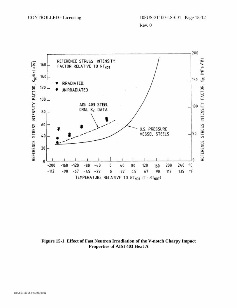
CONTROLLED - Licensing 108US-31100-LS-001 Page 15-12
Rev. 0
108US-31100-LS-001 2003/08/12
Figure 15-1 Effect of Fast Neutron Irradiation of the V-notch Charpy Impact Properties of AISI 403 Heat A

CONTROLLED - Licensing 108US-31100-LS-001 Page 15-13
Rev. 0
108US-31100-LS-001 2003/08/12
Figure 15-2 CHARPY V-Notch Impact Properties of AlSl Type 403 Low Residual Stainless Steel (Upper) and of High Residual Material (Lower)

CONTROLLED - Licensing 108US-31100-LS-001 Page 16-1
Rev. 0
108US-31100-LS-001 2003/08/12
16. CALANDRIA TUBE PERFORMANCE
16.1 Introduction
The Zircaloy-2 calandria tubes in the CANDU reactors isolate the relatively cool D2O moderator from the hot pressure tubes. In normal reactor operation, four spacers, the “garter springs” prevent contact between each pressure tube and its calandria tube. The annulus thus formed between the tubes contains the recirculating annulus gas (carbon dioxide with or without additional oxygen) the dew point of which is monitored for indications of leakage in the channel. The pressure tube, being horizontal, is loaded by the weight of the fuel and water of the heat transport system. The sag of the pressure tube, due to irradiation creep, results in a transfer of this load to the calandria tube and, over most of the reactor life, the sag resistance of the overall channel is determined by the creep resistance of the calandria tube. During normal reactor operation the calandria tube temperature is determined by the moderator outlet temperature set point, which for CANDU 6 reactors is typically about 70°C. The tube operates in a peak neutron flux of about 3 x 10¹⁷ n/(m2.s) (E>meV).
Also during normal operation, the maximum tensile stress in both longitudinal and transverse directions through the bulk of the tube is so low, <100 MPa that in the absence of neutron irradiation negligible creep deformation would occur. The neutron irradiation affects several properties of the tube, viz.
a) Creep rate will be enhanced
b) A shape change independent of stress, “growth”, will occur
c) The tensile strength will increase
d) The tensile ductility will decrease.
Because of the low temperature of the calandria tube during operation little hydrogen pickup is expected and, combined with the low stress, no problem is anticipated from delayed hydride cracking. A small number of calandria tubes have been removed from CANDU reactors after significant periods of operation, primarily during the large scale fuel channel replacement operation for the Pickering A reactors in the late 1980’s and early 1990’s. Tests on material from these tubes have resulted in the accumulation of a large body of data on calandria tube properties.
16.2 The Unirradiated Tubes
16.2.1 Fabrication
As for pressure tubes, the manufacture of calandria tubes for CANDU reactors commenced over 40 years ago. To date, more than 13,000 tubes have been produced and installed in reactor units located within Canada and overseas and have provided exemplary service. All calandria tubes to date contain a longitudinal seam weld and are made from Zircaloy-2 (16.1 and 16.2), but future reactors may use stronger seamless calandria tubes (16.3) made from either Zircaloy-2 or

CONTROLLED - Licensing 108US-31100-LS-001 Page 16-2
Rev. 0
108US-31100-LS-001 2003/08/12
Zircaloy-4. The welded calandria tubes have been made according to manufacturing routes similar to the current manufacturing route shown in Figure 16-1 with the qualified suppliers of the strip material being Wah Chang in the USA or CEZUS in France. The glass-bead peening is a recent addition to the fabrication process that improves heat transfer to the moderator during some potential high temperature accident conditions.
Final fabrication of the tubes has been by Carpenter Technology, Westinghouse Canada (now Zircatec Precision Industries) and Bristol Aerospace, although all recent final fabrication has taken place at Zircatec in Port Hope, Canada. Whilst the starting material has always been annealed Zircaloy-2, minor variations in both the fabrication of the ingot into strip and the final fabrication techniques have resulted in some minor variation in properties from batch to batch.
16.2.2 Uniaxial Strength
The tubes are produced to a specified minimum uniaxial strength at room temperature, which for recent calandria tubes is as follows:
Longitudinal
Direction (MPa)
Transverse
Direction (MPa)
0.2% Yield Stress (YS) 320 320
UTS 425 415
The total elongation in these tests must be >20% and in practice has been exceeded. The tests are done at a strain rate in the range 5 x 10⁻⁵ to 1.16 x 10⁻⁴ s-1 until the 0.2% YS is exceeded, and at a nominal strain rate of 8.3 x 10⁻⁴ s-1 to failure. The minimum values of 0.2% YS are those required to resist tube permanent deformation from moderator water pressure during poison injection. Initially, some problems were encountered in meeting the minimum 0.2% YS in the transverse direction, but recent tubes fabricated from strip made at Wah Chang and CEZUS have exceeded the specified strengths by a wide margin as a consequence of manufacturing process improvements.
In addition to the tests required by the specification, the uniaxial tensile properties of the tubes have been studied in considerable detail. The tensile strength, derived from tensile specimens fabricated from finished calandria tubes, exhibits the characteristics of annealed Zircaloy-2, with a near linear decrease in strength with increasing temperature in the range from room temperature up to ≈325°C, Figure 16-2. Also, the material exhibits significant increments in strength with increasing strain rate, Figure 16-3. The tensile strength in the longitudinal direction in the tubes is normally stronger than the transverse direction. This difference is due to the Bauschinger effect resulting from the final sinking of the tubes in fabrication since this operation occurs after the recrystallization anneal.

CONTROLLED - Licensing 108US-31100-LS-001 Page 16-3
Rev. 0
108US-31100-LS-001 2003/08/12
16.2.3 Biaxial Strength – Unirradiated
Severe loading of the calandria tube can arise if a pressure tube ruptures resulting in rapid internal pressurization of the calandria tube [16.4]. This has occurred in two incidents noted in the following (See (ii) and (iv) of Subsection 16.6). In all CANDU reactors any longitudinal strain in individual tubes is severely restrained by the high stiffness of the calandria tube sheet. Thus, it is relevant to consider the internally pressurized tube, in such cases, as stressed in a fixed-end mode. Burst test results obtained in this loading mode for two unirradiated tubes are shown in Table 16-1. In this mode, the failure of unirradiated and irradiated calandria tubes always occurs in the weld area due to localized wall thinning. This occurs primarily because the crystallographic texture of the weld that produces a locally increased wall thinning response in this loading mode. In transverse, uniaxial tension tests (i.e. across the weld zone) the weld zone is stronger than the remainder of the tube. This anisotropy of the plasticity is being exploited to develop stronger, seamless calandria tubes for use in future reactors or during retubing of current reactors.
16.3 The Irradiated Tubes
16.3.1 Uniaxial Strength
The strengthening of Zircaloy-2 from neutron irradiation has been demonstrated in many separate investigations and particularly at the temperature relevant to the calandria tube operation. Thus, it was never felt necessary to repeat the tests on specimens of calandria tube material. However, with the removal and testing of some tubes from operating reactors, data are now available. Tensile test results from the tubes removed from operating CANDU reactors are listed in Table 16-2, illustrating the strengthening from irradiation and the retention of ductility after irradiation [16.5]. Longitudinal and transverse tensile data at both low and high strain rates, the latter being applicable to conditions under a pressure tube rupture scenario, have supported these observations [16.6].
16.3.2 Biaxial Strength
Six fixed-end burst tests have been done on tubes removed from Pickering 2; the results are listed in Table 16-3. The tests were done at 170°C, estimated to be the average temperature of the calandria tube when internally pressurized with primary coolant. There were no lengths of these tubes available for testing in the unirradiated condition, and the effect of the in-reactor service has to be deduced either from the tensile properties at room temperature before irradiation or the burst test results in Table 16-1. Comparing the results at 170ºC from Tables 16-1 and 16-3, the consequence of irradiation is a large increment in 0.2% YS and a smaller increase in the UTS together with a possible reduction in the total elongation, although the results are erratic.

CONTROLLED - Licensing 108US-31100-LS-001 Page 16-4
Rev. 0
108US-31100-LS-001 2003/08/12
16.4 In-Reactor Deformation
16.4.1 Creep Resistance
At the operating stresses and temperatures of calandria tubes the creep of annealed Zircaloy-2 decreases with time in the absence of neutron irradiation, Figure 16-4, and becomes insignificant after about 100,000 h. Irradiation induces steady creep rates in the long term, which varies linearly with the neutron flux [16.7, 16.8]. In-reactor creep of Zircaloy-2 has been evaluated by means of uniaxial, biaxial (pressurized capsule) and stress relaxation-in-bending tests [16.9,16.10]. Very long periods of time, i.e. >10 000 h, were required to obtain reliable values. The current best estimate for strain rate as a function of stress at 50°C is presented in Figure 16-5. The stress dependence of creep rate up to about 100 MPa is linear, and little difference has been found between creep in the longitudinal and transverse directions for calandria tubes made from batch-annealed strip. The axial creep rate of calandria tubes is generally small compared to that in the transverse direction. It can also have a negative creep rate. The variations in texture between a continuous-annealed strip as compared to that of a batch annealed strip can result in large variations in the axial creep rate. The texture variations can induce transverse creep rate variations of 30% [16.11].
16.4.2 Irradiation Growth
The irradiation growth behavior of calandria tube material has been investigated very extensively in high flux at the Advanced Test Reactor (ATR) at Idaho Falls. Some of the test specimens have reached fluences equivalent to 30 years in the power reactor, Figure 16-6. Incentive for this work arose from indications in the literature [16.12] of an acceleration in growth at fluences ≈5 x 1025 n/m2, which might lead to undue movement of the end shield; a tube elongation of >~0.3% might be unacceptable. The results of the ATR tests show marked variation in the growth behavior among the tubes from the different reactors, but none of them show acceleration of the growth rate to fluences investigated. It seems evident that tube elongations from growth can remain well below the 0.3% upper limit.
16.5 Resistance to Crack Growth
16.5.1 Potential Failure Mechanisms
Crack growth in the calandria tubes (as differentiated from tensile overload) could occur via three mechanisms, viz.
- Exceeding some stress intensity factor KIC or elastic plastic equivalent parameter,
- Delayed hydride cracking by exceeding the threshold stress intensity factor, KIH, or
- Fatigue.

CONTROLLED - Licensing 108US-31100-LS-001 Page 16-5
Rev. 0
108US-31100-LS-001 2003/08/12
This topic has not received as much attention as others discussed in this paper, largely because initial work on the topic always showed that the probability of substantial crack growth in the tubes in reactors was remote.
It is highly unlikely that any of the calandria tubes enter service with cracks of depth >0.17 mm and the stress intensity factor resulting from applied loads is too low to be of concern. A second stress condition could arise in the calandria tube at garter spring locations if the springs are pinched between pressure and calandria tube (a situation termed nip-up) due to diametral creep of the pressure tube. This condition is not anticipated in any recent reactors or in future reactors although it may occur in some of the earlier reactors. Additional analysis has been undertaken for these situations.
16.5.2 Delayed Hydride Cracking
There is no expectation that delayed hydride cracking will occur in calandria tubes even though hydrides are likely to be present in the material at operating conditions. K1H is expected to be significantly higher in irradiated calandria tube than in pressure tube material both because of the lower strength and because hydrides will not be easily oriented into the radial direction due to the absence of basal planes of the alpha zirconium in that direction.
16.5.3 Fatigue
The matter of fatigue crack growth in the calandria tubes has been reviewed and it has been concluded that failure by fatigue is highly unlikely in calandria tubes.
16.6 Reactor Experience
In total seven calandria tubes have been removed and replaced in CANDU reactors.
i) From Douglas Point in 1967, soon after startup, when failure of a coupling lock caused fretting damage between a booster rod flow tube and the calandria tube. From the design viewpoint, no part of this failure could be attributed to the calandria tube.
ii) From Pickering 2 channel G-16 in 1983. The calandria tube withstood full primary coolant conditions of pressure and temperature applied when a pressure tube spontaneously ruptured.
iii) From Pickering 2 channel K-13 in 1985. The tube was removed to provide a second set of data to compare with that obtained from P2G16.
iv) From Bruce 2 channel N06 in 1986. The tube split along most of its length when the pressure tube ruptured suddenly during a cold, pressurized, leak search activity. The calandria tube was pressurized quickly with cold, 30°C, water. Subsequent analyses has shown that failure of the calandria tube is expected for this type of incident. The tube in channel N06 was stressed beyond its ultimate tensile strength. With the reactor shutdown and cold the failure was not a safety concern.

CONTROLLED - Licensing 108US-31100-LS-001 Page 16-6
Rev. 0
108US-31100-LS-001 2003/08/12
v) From Pickering A, Unit 4, channel M11 in 1991. This tube was replaced as part of a formal survey program designed to expand the knowledge base on calandria tubes irradiated to a high fluence
vi) From Pickering A, Unit 4, channel J09 in 1991. This tube was replaced both as part of a formal survey program designed to expand the knowledge base on calandria tubes irradiated to a high fluence and also since it had been in contact with the pressure tube for an extended period of time
vii) From a 480-channel CANDU in 2002. This tube was replaced due to a flaw generated during maintenance activities
In no instance has the tube been removed because of a failure in its design mode of operation.
The corrosion behavior of the tubes in-reactor has been exemplary. For each of the Pickering and Bruce tubes the oxide layer has been too thin to measure accurately, i.e. <1 µm, and hydrogen pickup was extremely low, i.e. average deuterium concentrations <~1.4 mg/kg; this is after the service lives of 87,000 EFPH for the Pickering 2 tubes and 66,500 EFPH for the Bruce 2 N06 tube. The tubes are expected to sag, by creep, the load being transmitted through the annulus spacers. Empirical models of deformation of calandria tubes, based upon experiments conducted on small specimens under irradiation, have been developed and are currently incorporated in CDEPTH (see Chap 8), a program for calculations of fuel channel sag. Channel sag measurements are described in Section 11. In ACR, the calandria tube thickness and diameter are both increased relative to those in current CANDUs and the sag rates are predicted to be significantly reduced.
Length changes in the tubes can be expected, from the growth of the material, which occurs independently of stress. There would also be a small elongation due to the axial stress in the tubes. Changes, if any, have thus far been undetected at the reactor sites.
16.7 Summary and Conclusions
The performance of calandria tubes in CANDU reactors has been excellent to date. Changes in the mechanical properties of the material due to irradiation are unlikely to present a channel life limit and are well characterized. Dimensional changes due to irradiation deformation processes have been measured and successfully modeled.
16.8 References
[16.1] C.E. Ells, C.E. Coleman, E.T.C. Ho, and A.R. Causey, “The Behavior of the CANDU Calandria Tubes”, Atomic Energy of Canada Limited Report AECL-9514, July 1987
[16.2] E.G. Price and P.J. Richinson, “Thin-Walled Large-Diameter Zirconium Alloy Tubes in CANDU Reactors”, Atomic Energy of Canada Limited, Report AECL-6345, August 1978

CONTROLLED - Licensing 108US-31100-LS-001 Page 16-7
Rev. 0
108US-31100-LS-001 2003/08/12
[16.3] J.R. Theaker and C.E. Coleman, “Development of Crystallographic Texture in CANDU Calandria Tubes”, Zirconium in the Nuclear Industry: Thirteenth International Symposium, ASTM STP 1423, G.D. Moan and P. Rudling Eds, ASTM International, West Conshohocken, PA 2002, pp. 449-467
[16.4] C.E. Ells, C.E. Coleman, R.R. Hosbons, E.F. Ibrahim and G.L. Doubt, “Prospects for Stronger Calandria Tubes”, AECL Report, AECL-10339, 1990 December
[16.5] C.E. Ells, C.E. Coleman and C.K. Chow, “Properties of a CANDU Calandria Tube”, Canadian Metallurgical Quarterly, Vol. 24, No 3, pp. 215-223, 1985
[16.6] R.W.L. Fong, C.E. Coleman, R.S.W. Shewfelt, P.J. Ellis, Y. Tsuchimoto, S. Yoshie, Y. Morishita, E.V. Pizzinato and C. Albertini, “Tensile Properties of Irradiated Calandria Tubes at Low to High Rates of Strain”, AECL Report, AECL-11816, 1997 July
[16.7] V. Fidleris, “The Effect of Texture and Strain Aging on Creep of Zircaloy-2”, ASTM STP 458 (1969) p. 1.
[16.8] V. Fidleris, “Primary Creep of Zircaloy-2 under Irradiation”, ASTM STP 681 (1979) p. 177.
[16.9] A.R. Causey, G.J.C. Carpenter, and S.R. MacEwen, “In-Reactor Stress Relaxation of Selected Metals and Alloys at Low Temperatures”, J. Nuc. Mat. 90 (1980) p. 216.
[16.10] E.F. Ibrahim, “In-Reactor Deformation of Zirconium Alloy Tubes at 330 K”, J. Nuc. Mat. 101 (1981) p. 1.
[16.11] R.J. Klassen, A.R. Causey, and N. Christodoulou, “Dependence of Irradiation Creep of Zircaloy-2 at 340K on Microstructure “. Proceedings of 5th International Conference on Creep of Materials, “CREEP: Characterization, Damage and Life Assessment”, D.A. Woodford, C.H.A. Townley and M. Hnami, Eds., ASM International, Lake Buena Vista, Florida, USA, 18-21 May 1992 Pg 43.
[16.12] A. Rogerson, and R.A. Murgatroyd, “Breakaway Growth in Annealed Zircaloy-2 at 353 K and 553 K”, J. Nuc. Mat. 113 (1983) p. 256.

CONTROLLED - Licensing 108US-31100-LS-001 Page 16-8
Rev. 0
108US-31100-LS-001 2003/08/12
Table 16-1 Burst Test Results on Two Unirradiated Calandria Tubes in the Fixed End Mode
at a Strain Rate of 10-3 s-1
Tube No Test Temp. °C
0.2% Y.S MPa
UTS MPa
Total Circumferential Elongation
% P-646 RT 505 734 2.0 80 415 662 3.0 170 325 538 4.0 G-033 RT 425 686 2.0 80 375 655 2.0 170 275 540 2.0
Table 16-2 Tensile Properties of the Calandria Tube Removed from Operating CANDU Reactors
Source Estimated Fluence n/m2 E
> 1.0 MeV
Direction Test Temp 0.2% YS MPa
UTS MPa
% Total Elong
% Reduction
in Area
L RT 605 635 7.8 38 T RT 531 615 9.8 38 L 170°C 473 488 7.3 43
P2 G16 6.1
T 170°C 384 445 11.7 48 L RT 652 653 5.1 24 T RT 527 638 7.3 25 L 170 518 518 6.9 30
P4M11 8.1
T 170 541 541 8.8 36 L RT 660 672 7.2 23 T RT 575 654 9.5 29 L 170 541 541 8.8 36
P4J09 8.1
T 170 575 654 9.5 29 Typical 0 L RT 365 483 25 28
T RT 334 470 24 33 L 170 223 295 42 40 T 170 215 284 41 44

CONTROLLED - Licensing 108US-31100-LS-001 Page 16-9
Rev. 0
108US-31100-LS-001 2003/08/12
Table 16-3 Properties of Calandria Tubes Burst in a Fixed End Condition at 170°°°°C
TUBE FLUENCE n/m2 x 10-25 E > 1.0 MeV
HOOP 0.2% YS
MPa
HOOP UTS MPa
% ELONG.
P2G16 4.0 555 580 6.0* P2G16 5.5 575 580 2.3 P2K13 4.0 490 530 0.5 P2K13 6.0 - 622 0.1 P2K13 5.8 535 585 4.0 P2K13 1.4 450 520 5.0
* not ruptured

CONTROLLED - Licensing 108US-31100-LS-001 Page 16-10
Rev. 0
108US-31100-LS-001 2003/08/12
Triple Melt Zircaloy-2 or Zircaloy-4 Ingot
Fabricate into Strip (forge, hot roll, beta solution anneal and quench, cold
roll with intermediate and final anneals)
Brake-form Strip into Open Tubular Hollow
Seam-weld into Closed Tube Section
Bead-roll the Seam-weld Flat
Recrystallization Anneal at About 750°C
Sink about 1.5% to Size and Shape
Correct any Ovality and Straighten
Inspection
Glass-bead Peen Outside Surface
Stress Relieve at 500°C
Bell Ends
Final Inspection
Figure 16-1 Simplified Seam Welded Calandria Tube Fabrication Flow Chart

CONTROLLED - Licensing 108US-31100-LS-001 Page 16-11
Rev. 0
108US-31100-LS-001 2003/08/12
Figure 16-2 The Ultimate Tensile Strength in the Longitudinal Direction as a Function of Temperature of Three Typical Calandria Tubes. The tests were done with a controlled
strain rate of 10-3s-1.
Figure 16-3 The Ultimate Tensile Strength in the Longitudinal Direction as a Function of Strain Rate at 80°°°°C of the Same Tubes as in Figure 16-2

CONTROLLED - Licensing 108US-31100-LS-001 Page 16-12
Rev. 0
108US-31100-LS-001 2003/08/12
Figure 16-4 The Creep of Annealed Zircaloy-2 at 50°°°°C, Longitudinal Direction
Figure 16-5 The In-Reactor Creep of Calandria Tube Material (Longitudinal Direction) at 50°°°°C, and Neutron Flux of 2 x 10l7 n/m2.s) E > 1.0 MeV, as a Function of Stress

CONTROLLED - Licensing 108US-31100-LS-001 Page 16-13
Rev. 0
108US-31100-LS-001 2003/08/12
Figure 16-6 The Irradiation Growth Behavior in the Longitudinal Direction at 60°°°°C of Specimens taken from Different Production Runs of Calandria Tubes and Irradiated in the
High-Flux ATR
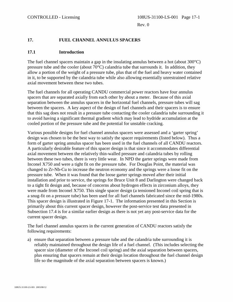
CONTROLLED - Licensing 108US-31100-LS-001 Page 17-1
Rev. 0
108US-31100-LS-001 2003/08/12
17. FUEL CHANNEL ANNULUS SPACERS
17.1 Introduction
The fuel channel spacers maintain a gap in the insulating annulus between a hot (about 300°C) pressure tube and the cooler (about 70°C) calandria tube that surrounds it. In addition, they allow a portion of the weight of a pressure tube, plus that of the fuel and heavy water contained in it, to be supported by the calandria tube while also allowing essentially unrestrained relative axial movement between these two tubes.
The fuel channels for all operating CANDU commercial power reactors have four annulus spacers that are separated axially from each other by about a meter. Because of this axial separation between the annulus spacers in the horizontal fuel channels, pressure tubes will sag between the spacers. A key aspect of the design of fuel channels and their spacers is to ensure that this sag does not result in a pressure tube contacting the cooler calandria tube surrounding it to avoid having a significant thermal gradient which may lead to hydride accumulation at the cooled portion of the pressure tube and the potential for unstable cracking.
Various possible designs for fuel channel annulus spacers were assessed and a ‘garter spring’ design was chosen to be the best way to satisfy the spacer requirements (listed below). Thus a form of garter spring annulus spacer has been used in the fuel channels of all CANDU reactors. A particularly desirable feature of this spacer design is that since it accommodates differential axial movement between the relatively thin-walled pressure and calandria tubes by rolling between these two tubes, there is very little wear. In NPD the garter springs were made from Inconel X750 and were a tight fit on the pressure tube. For Douglas Point, the material was changed to Zr-Nb-Cu to increase the neutron economy and the springs were a loose fit on the pressure tube. When it was found that the loose garter springs moved after their initial installation and prior to service, the springs for Bruce Unit 8 and Darlington were changed back to a tight fit design and, because of concerns about hydrogen effects in zirconium alloys, they were made from Inconel X750. This single spacer design (a tensioned Inconel coil spring that is a snug-fit on a pressure tube) has been used for all fuel channels fabricated since the mid-1980s. This spacer design is illustrated in Figure 17-1. The information presented in this Section is primarily about this current spacer design, however the post-service test data presented in Subsection 17.4 is for a similar earlier design as there is not yet any post-service data for the current spacer design.
The fuel channel annulus spacers in the current generation of CANDU reactors satisfy the following requirements:
a) ensure that separation between a pressure tube and the calandria tube surrounding it is reliably maintained throughout the design life of a fuel channel. (This includes selecting the spacer size (diameter of the Inconel coil spring) and the axial separation between spacers, plus ensuring that spacers remain at their design location throughout the fuel channel design life so the magnitude of the axial separation between spacers is known.)

CONTROLLED - Licensing 108US-31100-LS-001 Page 17-2
Rev. 0
108US-31100-LS-001 2003/08/12
b) have adequate strength to carry the loads imposed on them, without breaking or permanently deforming.
c) not corrode/degrade in the annulus environment.
d) allow essentially unrestrained differential axial movement between each pressure tube and the calandria tube surrounding it with minimal wear of the spacer and both tubes.
e) allow an adequate flow of annulus gas to pass though the fuel channel annulus.
f) provide a low heat transfer path from the reactor’s primary coolant to the moderator.
g) allow the pressure tube diameter to freely expand to its maximum predicted end-of-design-life magnitude, i.e., never have an interference fit of a pressure tube and spacer inside a calandria tube.
h) cause no unacceptable perturbation of pressure tube performance.
i) not interfere with the NDE that must be performed for some pressure tubes.
j) be relatively easy to install and allow the axial position of each spacer in a fuel channel annulus to be verified during (or shortly after) channel fabrication.
k) be compatible with the ability to replace pressure tubes efficiently.
l) have a neutron capture cross-section that is as low as practical.
m) during some accident conditions, allow sufficient contact between pressure and calandria tubes (by allowing sagging or ballooning of a pressure tube between the spacers) so the moderator can act as a heat sink and prevent pressure tube rupture.
17.2 Material and Design
Figure 17-1 is an illustration of the snug-fit annulus spacer design used in all fuel channels fabricated since the mid-1980s. These spacers are fabricated using Inconel X-750 wire that meets the requirements of AMS-5698D, #1 temper (UNS-7550). This wire, which has a 0.03 inch (0.76 mm) by 0.03 inch (0.76 mm) square cross-section, is coiled on a mandrel to form a coiled spring, which is subsequently heat-treated and centerless ground. Each spacer coil has an outside diameter of 0.19 inch (4.8 mm) and there are 15 coils per inch (25 mm) of spacer length. The wire at the two ends of each coiled spring is twisted to form a hook so these ends can be hooked together to form a ring that can be installed on a pressure tube as a ‘garter spring’. The free length of these coiled springs is such that they must be stretched at least 0.5 inch (13 mm) to fit on a pressure tube, thus these spacers are a snug-fit on a pressure tube.
Each spacer has a cold-drawn Zircaloy-2 ‘girdle’ wire that has a circular cross-section with a 0.05 inch (1.3 mm) diameter. It is oriented in the axial direction of the coiled spring and located inside the Inconel coils. This Zircaloy-2 wire is long enough so it wraps about 1.5 times around the pressure tube. Thus the ends of the girdle wire are overlapped, but they are not attached to each other. During reactor construction, this girdle wire allows the axial position of each spacer in a fuel channel to be detected from inside a pressure tube using an eddy current tool because the overlapped portion of the wire creates a loop that provides a continuous electrical path. In

CONTROLLED - Licensing 108US-31100-LS-001 Page 17-3
Rev. 0
108US-31100-LS-001 2003/08/12
addition, this overlapped girdle wire would tend to allow a spacer to continue to separate a pressure and calandria tube in the unlikely event that an Inconel coil might break, so the spacer would no longer be a snug-fit on the pressure tube.
17.3 Qualification Testing
An extensive test program was performed for the current fuel channel annulus spacer design using as-fabricated prototypes to qualify that these spacers would reliably satisfy their requirements. (In addition, in-service inspections have also verified that these fuel channel annulus spacers reliably satisfy their requirements.) A brief summary of the key portion of the qualification testing is given in the following.
17.3.1 Spacer Radial Compression Tests
During reactor operation, the fuel channel annulus spacers generally are ‘pinched’ between a pressure and calandria tube at their 6 o’clock (bottom) position, thus the coils in this region of the spacer have a load applied in the radial direction of the garter spring’s helix. The design load for this radial compression of the spacer coils is 200 pound (890 N) per spacer. Two inch (51 mm) lengths of prototype coiled springs, which is shorter than the spacer length that would be loaded in reactor, were slowly compressed (up to a maximum applied load of 1600 pound (7.1 kN)) at room temperature between dies that had the same curvatures as the inside of a calandria tube and the outside of a pressure tube. These radial compression tests indicate that the spacers ‘yield’ (0.001 inch (0.025 mm) permanent reduction of diameter) at an applied ‘static’ load of about 900 pound (4 kN) and had not collapsed (nor cracked/fractured) at a load of 1600 pound (7.1 kN).
17.3.2 Spacer Wear/Endurance Tests
During reactor operation, the fuel channel annulus spacers roll to accommodate differential axial movement between a pressure tube and the calandria tube surrounding it. This results in a cyclic loading for the spacer coils and some wear on the pressure tube, calandria tube and spacer. Thus, wear/endurance tests were performed to demonstrate that fatigue is not a concern and wear would be negligible. Prototype spacers installed between sections of a pressure tube and calandria tube at typical operating temperatures for the current generation of CANDU reactors were subjected to conservative loading conditions. The radial compressive load applied to the spacer coils was at least twice its 200-pound (890 N) design value and the number of cycles (pressure tube section being axially moved relative to the calandria tube section to simulate heat-up/cool-down of the reactor) was four times their design value. Post-test examination of the tested spacers showed an excellent resistance to both fatigue and wear during this cyclic loading as the test specimens had no distortion nor cracking and only negligible wear. A small but measurable wear occurred on the pressure and calandria tubes. The maximum depth of the wear marks for these tubes was only 0.002 inch (0.05 mm). Thus this testing demonstrates that rolling of the fuel channel annulus spacer between a pressure and calandria tube accommodates the differential axial movement between these two tubes with very little wear.

CONTROLLED - Licensing 108US-31100-LS-001 Page 17-4
Rev. 0
108US-31100-LS-001 2003/08/12
17.3.3 Channel Vibration Tests
During reactor construction, pressure tubes are installed (each being approximately concentric inside a calandria tube) a couple of years before the reactor starts to operate. During the subsequent stages of reactor construction, these pressure tubes do not contain either water or fuel and hence will have negligible sag. Thus most of the fuel channel annulus spacers, which are a snug-fit on the pressure tubes, will not contact the calandria tube surrounding them. During some stages of reactor commissioning the channels will be filled with water, but generally do not yet contain fuel. Thus, during commissioning the pressure tubes will still have only a very small amount of sag and most spacers will still not contact the calandria tube surrounding them. When fuel is inserted into a pressure tube, it will sag elastically so that about half of the fuel channel annulus spacers (most likely the two spacers nearest to the center of each pressure tube) become ‘pinched’ between a pressure and calandria tube at their 6 o’clock (bottom) position. During reactor operation, pressure tube sag will increase due to creep so that, after a few years of reactor operation, all four of the annulus spacers for each fuel channel will be ‘pinched’ between the pressure and calandria tubes. Until this time, there is a concern that channel vibration during reactor construction, commissioning or operation may cause the spacers to move axially in the fuel channel annulus, which might cause a sufficiently large axial separation between spacers so that pressure tube sag could result in pressure/calandria tube contact before the end of the fuel channel design life.
To demonstrate that such unacceptable spacer movement will not occur, a fuel channel assembly was fabricated/tested to confirm that prototype spacers remained at their installed locations during simulated reactor construction, commissioning and operating conditions. In these tests, which were conducted at room temperature, the full range of possible spacer loading conditions was addressed (from the four spacers in a fuel channel annulus not contacting the calandria tube surrounding them to all spacers contacting this tube and all other possible combinations of contact/non-contact). With spacers in their as-fabricated condition, the fuel channel test assembly was subjected to various low frequency vibrations that might occur during reactor construction. (The magnitude of these vibrations was conservatively large, e.g., end fittings ‘tilted’ the maximum amount allowed by their bearings.) In addition, a 0.5 kN (112 pound) shaker was used to excite vibrations in the horizontal fuel channel test assembly at frequencies between 3 and 50 Hz to conservatively simulate the fuel channel vertical vibration that will occur during reactor commissioning and operating conditions. The shaker tests were repeated using spacers in a stress-relieved condition that simulated a conservatively large reduction in the tightness of their fit on a pressure tube (spacer tension about a third of that for their as-fabricated condition). Measurements of spacer positions detected no movement of any of the tested spacers.

CONTROLLED - Licensing 108US-31100-LS-001 Page 17-5
Rev. 0
108US-31100-LS-001 2003/08/12
17.4 Post-Service Testing of Inconel X-750 Spacers
Four Inconel X-750 ‘garter spring’ spacers that were a snug-fit on pressure tubes in the NPD prototype reactor were retrieved after over 20 years of operation.1 As these are the only Inconel fuel channel annulus spacers for which post-service testing has been performed to date, the data obtained during this testing is presented in the following. The longest service time for these spacers is 156 900 Effective Full Power Hours (EFPH). A variety of tests were used to evaluate the effect of irradiation on the mechanical properties of these spacers. This included stretch tests, rising-load radial compression tests, radial compression fatigue tests and wear/endurance tests. A list of the mechanical tests performed on each spacer and the NPD fuel channel (e.g., C08) in which they had operated is given in Table 17-1.
17.4.1 Stretch Tests
In the post-service stretch tests, which were performed at room temperature, short segments of NPD spacers were loaded to failure, or until the spring segment being tested was straightened. The results of these stretch tests are summarized in Table 17-2. Multiple specimens were sectioned from each spacer with each specimen being identified by a number following the fuel channel designation (e.g., C08-2). This table also includes data for three test specimens obtained from an unirradiated NPD spacer. The unirradiated material, unlike the irradiated material, uncoiled without breaking.
Comparing the stretch test results for the irradiated and unirradiated specimens tested following the same procedure (CO8 and K05 vs. Unirradiated-1, 2 and 3), shows a slight reduction in the maximum load and a larger reduction in the corresponding displacement for the irradiated material. This reduction in spring extension is an indication of more brittle behavior and is consistent with the normally observed effect of irradiation on the mechanical properties of Inconel [17-1]. Examination of the fracture surfaces of the irradiated specimens indicated that their fractures had been ductile.
17.4.2 Radial Compression Tests
In the post-service rising-load radial compression tests, which were performed at room temperature, short segments (much shorter than the spacer length that would be loaded in reactor) of NPD spacers were compressed slowly between flat plates or curved anvils until
1 The cross-section of the Inconel X-750 wire used to fabricate spacers for NPD was
rectangular, 1.0 mm x 0.5 mm. This wire was coiled with the 1 mm dimension radial to give coils having a 4.5 mm outside diameter. There was one coil for each 1 mm length of this coil spring. It should also be noted that the fuel channel annuli for the NPD reactor were open to the reactor vault, i.e., these annuli were not sealed with their environment controlled to be very dry CO2, as exists for the current generation of CANDU reactors. All four spacers retrieved from NPD had negligible corrosion.

CONTROLLED - Licensing 108US-31100-LS-001 Page 17-6
Rev. 0
108US-31100-LS-001 2003/08/12
failure (collapse). The results of these tests are summarized in Table 17-3, which includes data for one test specimen obtained from an unirradiated NPD spacer. Comparing the test result for the unirradiated specimen to those for the irradiated specimens shows that irradiation caused an increase in the maximum load that the spacers could tolerate before collapsing. All of these test specimens survived loads much larger than a spacer’s in-service loading.
In the post-service radial compression fatigue tests, which were performed at room temperature, short segments of NPD spacers were again compressed between flat plates or curved anvils. These spacer segments were subjected to a cyclic compressive load at a frequency of 10 Hz. The testing sequence for spacers from NPD fuel channels C08 and K05, as well as for an unirradiated NPD spacer, is given in Table 17-4. The testing sequence for two segments from each of NPD spacers G07 and F08 is given in Table 17-5. (The test specimens were examined after completion of each line of the load cycling indicated in these tables.)
The results of the radial compression fatigue tests are summarized in Table 17-6, which shows that these tests were very successful. The test specimens from spacers that had operated in NPD fuel channels C08 and K05 withstood 60 000 cycles without any discernable evidence of damage. This included 10 000 cycles at a maximum load of 2100 N. These irradiated springs survived the same testing sequence as the unirradiated spacer. For the spacer from fuel channel G07, one specimen survived 50 000 cycles (including 20 000 cycles at a maximum load of 1500 N) with only a limited amount of damage. The second G07 specimen had a couple of coils break off after 15 000 cycles whose maximum load was 1820 N. Testing continued until the remaining section of this spacer shattered after 17 600 cycles. For the spacer from fuel channel F08, both specimens withstood at least 6000 cycles at 1800 N. All of these test specimens survived loads much larger than a spacer’s in-service loading.
17.4.3 Wear/Endurance Tests
In the post-service wear/endurance tests, a NPD spacer was a snug-fit on a short horizontal section of pressure tube that was mounted inside a short horizontal section of calandria tube. The pressure tube was maintained at 280°C and the calandria tube at 65°C. The spacer was ‘pinched’ between these two tubes at their 6 o’clock (bottom) position with a 1334 N load, plus an 8.9 N, 30 Hz vibrational force, being applied in the radial direction of the garter spring’s helix. During these tests, the pressure tube vibrated at 10 cycles per hour with a reciprocating motion in its axial direction whose amplitude was 2.5 mm. These wear/endurance tests were terminated after 15 000 cycles. Before and after the tests, the diameter of the spacers was measured at six locations. These results are given in Table 17-7. The NPD spacers survived this test without any measurable material loss and with no apparent damage.
17.5 Conclusions
The results of the qualification testing for prototypes of as-fabricated Inconel garter spring spacers of the design used for all fuel channels fabricated since the mid-1980s (Figure 17-1) indicate that these spacers have good strength and ductility. The results of the post-service testing of irradiated Inconel garter spring spacers of a similar earlier design indicate that they

CONTROLLED - Licensing 108US-31100-LS-001 Page 17-7
Rev. 0
108US-31100-LS-001 2003/08/12
remained in good condition, retaining both good strength and ductility. No concerns were raised regarding the long-term performance of such spacers.
Although the Inconel X-750 material from which the current design for CANDU fuel channel annulus spacers are fabricated loses some of its ductility when exposed to neutron irradiation, and is known to be susceptible to stress corrosion cracking (SCC) in an aqueous environment [17-1, 17-2, 17-3, 17-4], the current generation of CANDU spacers whose environment is a sealed fuel channel annulus controlled to contain very dry CO2 are expected to operate reliably without concern for their integrity.
17.6 References
[17.1] W.J. Mills, and B. Mastel, “Deformation and Fracture Characteristics for Irradiated Inconel X-750”, Nuclear Technology, 1986, Vol. 73, No. 1, pp 102-108.
[17.2] W.J. Mills, “Postirradiation Fracture Toughness of Inconel X-750”, Engineering Fracture Mechanics, 1983, Vol. 18, No. 3, pp 601-607.
[17.3] ASM Metals Handbook, Vol. 13, pp 651.
[17.4] R. Baja et al., “Irradiation-Assisted Cracking of HTH Alloy X750 and Alloy 625”, 7th International Symposium on Environmental Degradation of Materials in Nuclear Power Systems -Water Reactors, NACE International, Breckenridge, Colorado, August 7-10, 1995, pp 1093-1107.
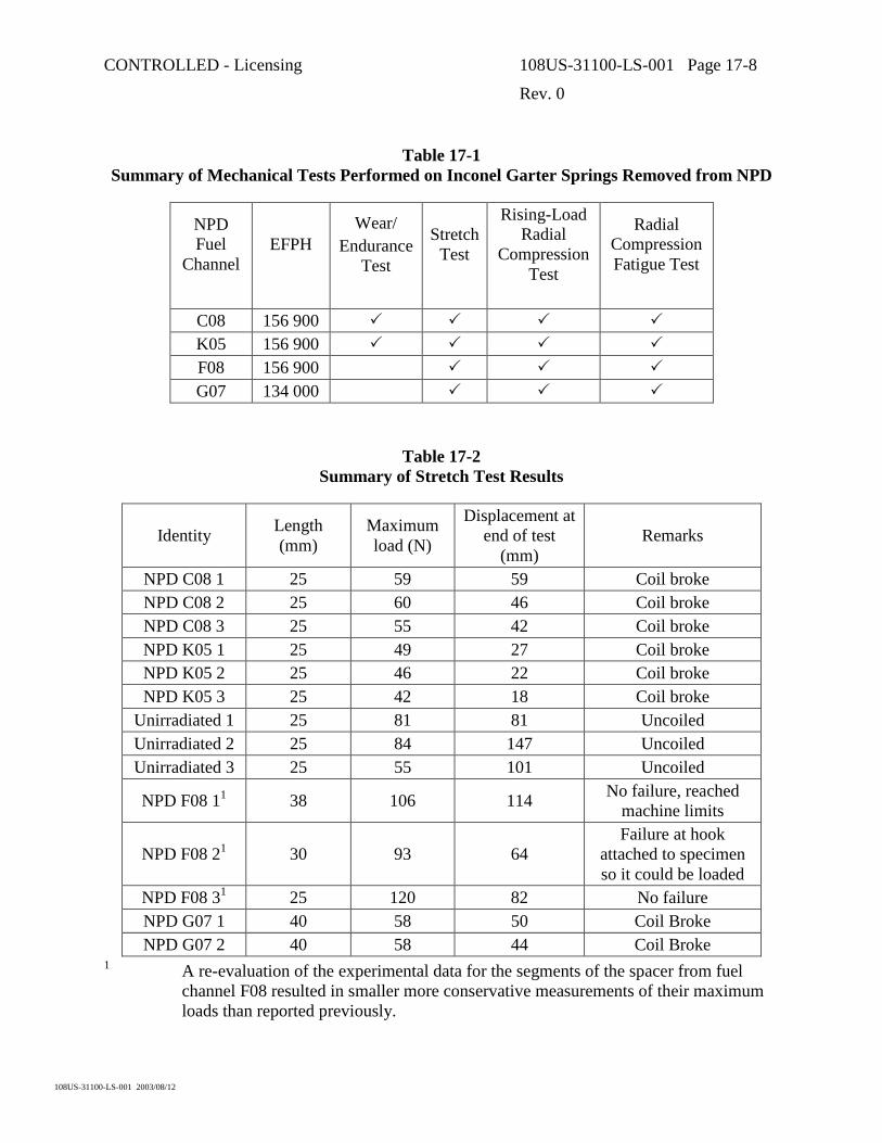
CONTROLLED - Licensing 108US-31100-LS-001 Page 17-8
Rev. 0
108US-31100-LS-001 2003/08/12
Table 17-1 Summary of Mechanical Tests Performed on Inconel Garter Springs Removed from NPD
NPD Fuel
Channel EFPH
Wear/ Endurance
Test
Stretch Test
Rising-Load Radial
Compression Test
Radial Compression Fatigue Test
C08 156 900 � � � � K05 156 900 � � � � F08 156 900 � � � G07 134 000 � � �
Table 17-2 Summary of Stretch Test Results
Identity Length (mm)
Maximum load (N)
Displacement at end of test
(mm) Remarks
NPD C08 1 25 59 59 Coil broke NPD C08 2 25 60 46 Coil broke NPD C08 3 25 55 42 Coil broke NPD K05 1 25 49 27 Coil broke NPD K05 2 25 46 22 Coil broke NPD K05 3 25 42 18 Coil broke
Unirradiated 1 25 81 81 Uncoiled Unirradiated 2 25 84 147 Uncoiled Unirradiated 3 25 55 101 Uncoiled
NPD F08 11 38 106 114 No failure, reached machine limits
NPD F08 21 30 93 64 Failure at hook
attached to specimen so it could be loaded
NPD F08 31 25 120 82 No failure NPD G07 1 40 58 50 Coil Broke NPD G07 2 40 58 44 Coil Broke
1 A re-evaluation of the experimental data for the segments of the spacer from fuel channel F08 resulted in smaller more conservative measurements of their maximum loads than reported previously.

CONTROLLED - Licensing 108US-31100-LS-001 Page 17-9
Rev. 0
108US-31100-LS-001 2003/08/12
Table 17-3 Summary of Rising-Load Compression Tests on NPD Fuel Channel Annulus Spacers
Identity Length (mm) Anvil type Maximum load (kN)
NPD C08 25 Flat 3.75 NPD C08 25 Flat 3.9 NPD K05 25 Flat 4.0
Unirradiated 25 Flat 2.79 NPD F08 20 Curved 7.8 NPD F08 20 Curved 4.7 NPD G07 20 Flat 3.85
Table 17-4 Radial Compression Fatigue Testing Sequence for Segments of an Unirradiated NPD
Spring and Springs from NPD Fuel Channels C08 and K05
Spring segments 25 mm long were tested between curved anvils
Load range, N Number of Cycles
100-1000 10 000
100-1500 +10 000 100-1800 +30 000 100-2100 +10 000

CONTROLLED - Licensing 108US-31100-LS-001 Page 17-10
Rev. 0
108US-31100-LS-001 2003/08/12
Table 17-5 Radial Compression Fatigue Testing Sequence for Spring Segments from NPD Fuel
Channels G07 and F08
Spring segments were 20 mm long
Specimen # Load range (N) Number of Cycles
100-528 10 000 100-750 +10 000 100-1000 +10 000 100-1500 +10 000
G07-1
100-1500 +10 000 15 000 +2500 G07-2 130-1820 +100 5000 F08-1 130-1800
+2500 5000 F08-2 130-1800
+1000
Table 17-6 Summary of Radial Compression Fatigue Testing Results
Fuel Channel Identification
Maximum load (N)
Anvil type
Condition at end of test
Unirradiated 2100 Curved No discernable deterioration C08 2100 Curved No discernable deterioration K05 2100 Curved No discernable deterioration
G07-1 1500 Flat 4 coils broke off after 10 000 cycles at
1500 N. Remaining section survived an additional 10 000 cycles.
G07-2 1820 Flat 15 000 cycles before 2 coils broke off. Specimen shattered after 17 600 cycles.
F08-1 1800 Curved Specimen failed after 7500 cycles F08-2 1800 Curved Specimen failed after 6000 cycles

CONTROLLED - Licensing 108US-31100-LS-001 Page 17-11
Rev. 0
108US-31100-LS-001 2003/08/12
Table 17-7 Diameter of Garter Springs from Two NPD Fuel Channels Before and After
Wear/Endurance Testing
Diameter before testing (mm)
Diameter after testing (mm) Location
C08 K05 C08 K05 1 4.470 4.493 4.516 4.529 2 4.516 4.496 4.521 4.511 3 4.534 4.496 4.498 4.516 4 4.536 4.511 4.463 4.498 5 4.516 4.519 4.514 4.506 6 4.511 4.503 4.519 4.516
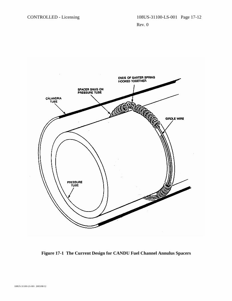
CONTROLLED - Licensing 108US-31100-LS-001 Page 17-12
Rev. 0
108US-31100-LS-001 2003/08/12
Figure 17-1 The Current Design for CANDU Fuel Channel Annulus Spacers

CONTROLLED - Licensing 108US-31100-LS-001 Page 18-1
Rev. 0
108US-31100-LS-001 2003/08/12
18. LIFE LIMITING CONSIDERATIONS IN FUEL CHANNEL COMPONENTS
18.1 Introduction
The engineering end-of-life for a fuel channel or for a complete reactor core in a CANDU reactor occurs when the fuel channels can no longer meet design requirements including stress limits, dimensional limits, and maintaining a sufficiently low probability of spontaneous pressure tube rupture. Since there is some tube-to-tube variability, the economic end-of-life for a reactor core may lie beyond that for the first channel to reach its limits as single channel replacements are possible. The purpose of this Section is to review how the engineering life limits are assessed.
18.2 Pressure Tubes
18.2.1 Stress Limits
Stress limits are determined by the pressure tube geometry (wall thickness, diameter and length), material properties and operating conditions. In-reactor deformation results in increasing levels of stress in the pressure tube as the diameter increases and the wall thickness is reduced. These increasing stresses are taken into account in the design (a portion of the irradiation strengthening of the tube is credited) and are acceptable for the design life. Elongation of the channel could result in other stress limits being reached if the bearing travel allowance is exceeded. If this occurs, the end fitting would no longer be properly supported on its bearings and, in current CANDUs, there would be potential for overstressing of the channel on cool down if the bearing condition prevented free contraction of the tube. Channel elongation also has an impact on stresses in the feeder pipes that are also taken into account in design.
Inspections are utilized to demonstrate that channels are operating within the design stress limits. Periodic inspections that measure tube diameters and wall thickness in a group of representative channels are used to demonstrate that, from a stress perspective, the channels are operating within design expectations. Channel positions on bearings have been measured in a variety of ways and each channel can be measured relatively easily. These have been described in Section 11.
Measurements of the mechanical properties of a small number of tubes removed for material surveillance provides supporting information to show that the mechanical properties are evolving under operation as expected.
18.2.2 Dimensional Limits
Dimensional limits that are not directly related to stress limits include the requirements to allow sufficient fuel cooling under all operating conditions, to not interfere with other devices in the reactor core, to avoid contact between the pressure tube and the calandria tube and to allow free fuel passage in the channel.

CONTROLLED - Licensing 108US-31100-LS-001 Page 18-2
Rev. 0
108US-31100-LS-001 2003/08/12
Diametral creep has the potential to affect fuel cooling as the cooling depends upon flow through the fuel bundles. As the diameter of the channel increases, some of the flow bypasses the bundle as the bundle sits on the bottom of the channel leaving a gap at the top. These effects, if they occur, can be compensated by fuel design (e.g. use of CANFLEX fuel in CANDU 6) and by small power reductions. For the current design of CANDU 6, these effects are not seen to be life limiting.
There are horizontal flux detectors and liquid injection shut down system nozzles between rows of channels in the current CANDU 6 reactors. Interference between the calandria tubes and these mechanisms could be life limiting for the channel if the sag of the channel were excessive: there is a potential for wear of the calandria tube in contact with these other devices that could lead to a calandria tube leak. Current designs will not reach these limits within the design life. Channel sag will not be as pronounced in the ACR design owing to the thicker, larger diameter calandria tube, thereby accommodating the tighter ACR lattice spacing with no contact.
Avoidance of contact between the pressure tube and the calandria tube is accomplished through the four, snug-fitting annulus spacers. Spacers in their design locations will prevent contact between the pressure tube and calandria tube for the design life with a significant time margin before contact could occur.
Sag of the pressure tube could also potentially result in a high enough curvature that free passage of the fuel would be impaired. This is not a life limit within the design life of current CANDU channels nor for the ACR design.
Assessments of dimensional limits can be made by inspection. Methods have been developed to measure the pressure tube diameters and the clearances between fuel channels and horizontal mechanisms in current CANDU reactors. As described in Section 11, technology also exists to measure both the gap between pressure tubes and calandria tubes and channel curvature.
18.2.3 Pressure Tube Integrity
Demonstrating that the tubes remain fit-for-service from the viewpoint of maintaining a sufficiently low probability of spontaneous rupture requires assessments of the mechanisms of potential degradation as well as a characterization of tube conditions in reactor. The Canadian Nuclear Industry has generated Fitness-for-Service Guidelines for Pressure Tubes in Operating Reactors that were modeled on the rules of ASME Section XI while taking into account the specific degradation mechanisms and flaw types that have been observed in CANDU pressure tubes. These guidelines have been in use for more than 10 years in the assessment and disposition of flaws found in pressure tubes during periodic and in-service inspection campaigns. The Guidelines have been revised and are now being incorporated into a new CSA Standard N285.8, currently in draft.
These guidelines are used to assess any flaws above a threshold size for crack initiation, crack growth and stability under all design loading conditions for an evaluation period. The crack initiation and growth mechanisms include fatigue and delayed hydride cracking. The evaluation period defines a number of load and thermal cycles for which the flaws must be evaluated. An

CONTROLLED - Licensing 108US-31100-LS-001 Page 18-3
Rev. 0
108US-31100-LS-001 2003/08/12
assessment is made of the maximum potential flaw size at the end of the evaluation period. The flaw must be demonstrated to have an acceptable safety margin against both crack instability and plastic collapse. The margins for the different loading conditions are similar to those in ASME Section XI.
Since delayed hydride cracking can only occur at a flaw under load when the combination of temperature, hydrogen concentration in the material and stress or stress intensity factor allows the mechanism to operate, the evaluations of flaws for DHC require assessments of the hydrogen concentrations in the tube with the flaw as well as the loading as a function of temperature for temperatures below normal operating temperature.
In addition to the assessment of flaws, the guidelines also allow for the assessment of pressure tubes known, or suspected to be, in contact with their surrounding calandria tubes. These guidelines were developed in order to be able to assess fuel channels with annulus spacers displaced from design locations. This occurred in a number of the early reactors having a spacer design that was not sufficiently resistant to displacement by vibration. Prior to SLAR (Spacer Location and Repositioning) a number of channels in each reactor could have been in contact with their respective surrounding calandria tubes. Assessments, based upon the understanding of the effects of pressure tube to calandria tube contact on hydride blister formation and growth in the pressure tubes, were required to demonstrate the acceptability of such contacts. The guidelines provide the means of carrying out such assessments. The assessments must show that hydride blisters cannot be potentially actively growing in the pressure tubes at the contact locations at operating conditions. An assessment for a pressure tube known to be in contact for which the acceptance criteria could not be met would result in the need to get more information (for example, to use measured hydrogen isotope concentrations in the particular tube rather than an upper bound estimate), to remove the tube from contact through SLAR, or to replace the channel.
Other assessments are required to demonstrate that a postulated part–through or through wall flaw would not be unstable under any design loading condition with a defined safety factor. The size of the postulated flaw must be chosen to represent a flaw that could potentially exist and not be leaking. The through-wall flaw is usually taken to be the maximum length of a locally-initiated crack that has just penetrated the pressure tube wall (i.e. the penetration length). This type of assessment provides protection against fracture by requiring that the reactor be operated within a pressure-temperature envelope that provides the necessary margins.
A final requirement is the necessity to demonstrate leak-before-break if the pressure tube is considered to have hydrogen concentrations higher than the terminal solid solubility at sustained hot conditions. Such a condition is conservatively assessed as allowing a sufficiently large crack to grow continuously. The assessment of leak-before-break has been described in Section 12. If leak-before-break can not be demonstrated using upper-bound crack growth rates and lower-bound fracture toughness and operations cannot be changed to reduce response times for reactor shutdown and depressurization, then the channel would have reached its end-of–life. A similar leak-before-break assessment is required for the most limiting channel in the reactor core.
CONTROLLED - Licensing 108US-31100-LS-001 Page 18-4
Rev. 0
108US-31100-LS-001 2003/08/12
Probabilistic techniques are being introduced for carrying out reactor core assessments for crack initiation from flaws. These techniques are used to calculate a crack initiation frequency for the reactor core. Extension of the techniques to the estimate of the pressure tube rupture frequency allows direct comparison with acceptance criteria in safety reports.
From a single pressure tube integrity viewpoint, the end-of-life occurs if a detected flaw cannot be demonstrated to be acceptable and cannot be repaired. For a reactor core, the end of life occurs when no changes to operations can effectively maintain the estimated frequency of pressure tube rupture within the acceptance criterion used for the safety report analysis.
The mechanical properties required to make these integrity assessments, together with their evolution with operating time have been described in Sections 10 and 12. Mechanical property data obtained from surveillance tubes removed from the reactors with the largest operating time continue to extend the database for Zr-2.5Nb material to higher fluences and higher hydrogen isotope concentrations. As indicated in the foregoing, knowledge of the hydrogen isotope concentrations in the tubes in the core is also essential in making integrity assessments. The evolution of the hydrogen concentrations with operating time has been described in Section 9. Together with inspection data, pressure tube life assessments can be carried out.
As noted in Section 13, decisions have been taken in the past that fuel channels had reached the ends of their engineering lives. In the cases of the NPD reactor and the reactors in Pickering Units 1 and 2, the mechanical properties and the hydride blisters in the pressure tubes respectively, were determined to be unacceptable. The decisions to shut the reactor (NPD) and to replace fuel channels (Pickering Units) were taken prior to the development of the Fitness-for-Service Guidelines. CANDU reactors in Canada today must meet the requirements of the guidelines as outlined above. The guidelines are also being used to assess inspection results from reactors overseas.
18.3 Calandria Tubes
The operating environment for calandria tubes is much less severe than that for the pressure tubes. Cracking of calandria tubes is unlikely because the stresses are low. The sag resistance of the fuel channel is provided by the calandria tube and the life of the calandria tubes in current reactors will probably be determined by their sag.
18.4 End Fittings
The operating environment for the end fittings is less severe than that of the pressure tubes and only the inboard ends are exposed to the neutron flux. Hydrogen is absorbed from the PHT by the bulk of the end fitting, but passes either into the annulus or into the end of the pressure tube at the rolled joint. The flaw tolerance of the 403 Stainless Steel remains high after irradiation; hence, the end fittings are not expected to be a factor in the service life of the fuel channel. The life limit of end fittings is certainly in excess of 40 years.

CONTROLLED - Licensing 108US-31100-LS-001 Page 18-5
Rev. 0
108US-31100-LS-001 2003/08/12
18.5 Garter Spring Spacers
The garter springs bear part of the load of the pressure tube, the fuel bundles and the heavy water in the pressure tube. While evidence is limited, Inconel X750 springs have performed satisfactorily for 25 years in NPD and the life of the new springs is predicted to be the design life of the channel, since there are no known deteriorating mechanisms.
18.6 Summary
The factors that determine the end-of-life for each of the major fuel channel components have been described. Of these components, the pressure tube is likely to be most life limiting due to its dimensional changes and material property changes with operating time. The expected dimensional changes are factored into the design: channels are expected to attain the specified design life from a dimension perspective. The experience to date with the evolution of mechanical properties, corrosion and hydrogen isotope ingress in Zr 2.5Nb pressure tube materials has been good. Improvements in the fracture toughness of the starting material for new reactors and the evolution of fracture toughness during operation provide a level of confidence that the pressure tubes will also be able to maintain a sufficiently low probability of rupture throughout their design lives.


![¾L¹w ,IÀ - iranpotk.com 8 (mm) Taper punch with knurled shank nHk]A ¾²ILºj IM ½k¹¹¨ ZnIi ¾L¹w Code No. L(mm) (gr) LS 1030 LS 1230 LS 1430 LS 1630 LS 1830 LS 2030 LS 2230](https://static.fdocuments.in/doc/165x107/5b190a547f8b9a46258c4235/lw-ia-8-mm-taper-punch-with-knurled-shank-nhka-iloj-im-k.jpg)