AE4-1327 Economized Vapor Injection (EVI) for ZF*KVE and ...R-404A, R-507, R-407A/C/F, R-448A and...
29
© 2019 Emerson 1 AE4-1327 R14 July 2019 Economized Vapor Injection (EVI) for ZF*KVE and ZF*K5E Compressors TABLE OF CONTENTS Safety Instructions ..................................................... 3 Safety Icon Explanation ........................................... 3 Instructions Pertaining to Risk of Electrical Shock, Fire, or Injury to Persons .......................................... 4 Safety Statements .................................................... 4 Introduction ................................................................ 5 Theory of Operation ................................................... 5 Nomenclature ............................................................. 5 Approved Refrigerants .............................................. 5 Approved Oils ............................................................ 5 Application Envelopes .............................................. 7 Control Requirements ............................................... 7 Pressure Controls ...................................................... 7 Pump Down Recommendations ............................... 7 Power Requirements ................................................. 7 ZF(D)*KVE-XXX Compressors Models ..................... 8 Discharge Temperature Control ............................... 8 Thermistor ............................................................ 8 Discharge Line Thermostat .................................. 8 Digital ZF**KVE Scroll Compressors ....................... 9 Low Temp Digital Compressor Operation.......... 11 Wet Injection required on ZF*KVE Envelope. ........ 11 DTC Valve Liquid Injection for ZF*KVE compressors. ...................................................... 11 DTC Installation .............................................. 11 Suggested Application Techniques for DTC .. 12 Compressor Or DTC Service ......................... 12 ZF(D)*K5E-XXX Compressors Models.................... 12 Discharge Temperature Protection with CoreSense™ Diagnostics for K5 Compressors ..... 12 Wet injection for ZF*K5E compressors. ............. 12 Thermostatic Expansion Valve (TXV) & Heat Exchanger ................................................................. 13 System Configuration ............................................. 13 Downstream Extraction ...................................... 13 Upstream Extraction ........................................... 13 Heat Exchanger Piping Arrangements ................... 13 System Design Guidelines: .................................... 14 Heat Exchanger Sizing ........................................... 14 Line Sizing .............................................................. 14 Heat Exchanger TXV Sizing ................................... 15 Solenoid Valve & Ball Valve ................................... 15 Current Sensing Relay ........................................... 17 Multiple Compressor Applications .......................... 17 Controlling Liquid Out Temperature ....................... 17 General Guidelines and More Information ............. 18 APPENDIXES Appendix A: Service Section: Copeland Scroll Demand Cooling for ZF*KVE Models. Appendix B: Temperature resistance values for sensor kit part number 998-0166-00
Transcript of AE4-1327 Economized Vapor Injection (EVI) for ZF*KVE and ...R-404A, R-507, R-407A/C/F, R-448A and...

© 2019 Emerson
1
AE4-1327 R14 July 2019
Economized Vapor Injection (EVI) for ZF*KVE and ZF*K5E Compressors
TABLE OF CONTENTS Safety Instructions ..................................................... 3
Safety Icon Explanation ........................................... 3 Instructions Pertaining to Risk of Electrical Shock, Fire, or Injury to Persons .......................................... 4 Safety Statements .................................................... 4
Introduction ................................................................ 5
Theory of Operation ................................................... 5
Nomenclature ............................................................. 5
Approved Refrigerants .............................................. 5
Approved Oils ............................................................ 5
Application Envelopes .............................................. 7
Control Requirements ............................................... 7
Pressure Controls ...................................................... 7
Pump Down Recommendations ............................... 7
Power Requirements ................................................. 7
ZF(D)*KVE-XXX Compressors Models ..................... 8
Discharge Temperature Control ............................... 8 Thermistor ............................................................ 8 Discharge Line Thermostat .................................. 8
Digital ZF**KVE Scroll Compressors ....................... 9 Low Temp Digital Compressor Operation.......... 11
Wet Injection required on ZF*KVE Envelope. ........ 11
DTC Valve Liquid Injection for ZF*KVE compressors. ...................................................... 11
DTC Installation .............................................. 11 Suggested Application Techniques for DTC .. 12 Compressor Or DTC Service ......................... 12
ZF(D)*K5E-XXX Compressors Models.................... 12
Discharge Temperature Protection with CoreSense™ Diagnostics for K5 Compressors ..... 12
Wet injection for ZF*K5E compressors. ............. 12
Thermostatic Expansion Valve (TXV) & Heat Exchanger ................................................................. 13
System Configuration ............................................. 13 Downstream Extraction ...................................... 13 Upstream Extraction ........................................... 13
Heat Exchanger Piping Arrangements ................... 13 System Design Guidelines: .................................... 14 Heat Exchanger Sizing ........................................... 14 Line Sizing .............................................................. 14 Heat Exchanger TXV Sizing ................................... 15 Solenoid Valve & Ball Valve ................................... 15 Current Sensing Relay ........................................... 17 Multiple Compressor Applications .......................... 17 Controlling Liquid Out Temperature ....................... 17
General Guidelines and More Information ............. 18
APPENDIXES
Appendix A: Service Section: Copeland Scroll Demand Cooling for ZF*KVE Models.
Appendix B: Temperature resistance values for sensor kit part number 998-0166-00

© 2019 Emerson
2
AE4-1327 R14
TABLE OF FIGURES Figure 1 - Circuit Diagram and cycle for EVI ............... 6 Figure 2 - EVI System Schematic ................................ 7 Figure 3 - 998-0166-00 Kit installation instructions ..... 9 Figure 4 - Copeland Digital Compressor ................... 10 Figure 5 - Typical Single Compressor System Schematic with Wet Injection ..................................... 10 Figure 6 - DTC valve position in EVI Compressors ... 11 Figure 7 - DTC valve assembly, explosion ................ 12 Figure 8 - Downstream Extraction ............................. 13 Figure 9 - Upstream Extraction .................................. 13 Figure 10 - H/X Piping Arrangement .......................... 13 Figure 11 - Saturated Injection Temperature Graph .. 15 Figure 12 - EVI Paralleling with HW Thermostatic Valves of Different Capacity....................................... 17 Figure 13 - EVI Paralleling with HW Electronic Expansion Valve (EXV) .............................................. 17 Figure 14 - Screenshot of Emerson’s Product Selection Software Showing the Maximum Subcooling Obtained When the Default ‘Automatic’ is Selected for Economizer Settings .................................................. 19 Figure 15 - Screenshot of the Product Selection Software Showing the Constant Liquid Temperature at Outset of the Subcooling Heat Exchanger ................. 19
Figure 16 - Medium Temperature ZF**KVE Envelope (R-404A/R-507) .......................................................... 20 Figure 17 - Low Temperature ZF**KVE and ZF**K5E Envelope (R-404A/R-507) .......................................... 20 Figure 18 - Medium Temperature ZF**KVE Envelope (R-407A/C/F, R-448A and R-449A) ............................ 21 Figure 19 - Low Temperature ZF**KVE Envelope (R-407A/C/F, R-448A and R-449A) ................................. 21 Figure 20 - ZF*K5E (Excluding ZF49K5E), ZF25KVE 22 Figure 21 - ZF*K5E Low Temperature Vapor Injection Operating Map ............................................................ 22 Figure 22 - Low Temperature Vapor Injection** Operation Map ............................................................ 23 Figure 23 - Typical Single Compressor System Schematic with obsolete Demand Cooling System (only for service purposes) ......................................... 25 Figure 24 - Demand Cooling Module Wiring Diagram (Obsolete, only for service purpose) .......................... 26 Figure 25 - IDCM: Digital module Digital Compressor Controller Wiring Diagram .......................................... 26
TABLES
Table 1- Low and High Pressure Control Settings for ZF*KVE and ZF*K5 EVI Scroll Compressors .............. 6 Table 2 - Discharge Line Thermostat Kit Numbers (not required with K5 models) ............................................. 9 Table 3 DTC valve Kit# 998-1000-52 (only used on ZF13KVE-T, ZF18KVE-T, ZF25KVE-T, ZF28KVE-T models) ...................................................................... 12
Table 4 Current Sensing Relay Kit ............................. 16 Table 5 - Vapor Injection Solenoid Orifice Size .......... 16 Table 6- Approximate EPR Settings .......................... 18 Table 7 - Demand Cooling Operating Setpoints and Control Actions ........................................................... 27
Revision Tracking R14
Pg. 5 – POE warning note updated.
Pg. 10 – Figure 5: Solenoid valve added in
recommended single compressor system schematic.
Revision Tracking R13
August 2018
Pg. 1 – Bulletin title changed.
Pg. 5 – Nomenclature changed for including K5 scrolls
compressors.
Pg. 8 – Phased-out note added to ZF24KVE model.
Pg. 8 – ZF54K5E model added to the list.
Pg. 7 – References changed in Control Requirements
section.
Pg. 5 – POE defined exclusive for ZF*K5 and ZF*KVE
Pg. 8 – Pg. 12 – ZF*KVE Section separated from
ZF*K5E Section for a better description.
Pg. 12 – Wet Injection section added. Definition of Wet
Injection rewrote.
Pg.24 – “Demand Cooling for Scroll” Section changed
adding notes about parts phased out for this system.
This section was moved as a Appendix at the end.
Pg. 9 – 998-0166-00 Kit Drawing added.
Pg. 9 – Explanation about ZF**KVE digital model added,
including new figures.
Pg. 11 – DTC valve section for ZF*KVE compressors
added.
Pg. 13 – Figures adjusted to explanation in Heat
Exchanger Sizing section.
Pg. 10 – Liquid Injection drawing updated.
Pg. 17 – Two drawing added to help explanation of DTC
valve function.

© 2019 Emerson
3
AE4-1327 R14
Safety Instructions
Copeland Scroll compressors are manufactured according to the latest U.S. and European Safety Standards.
Particular emphasis has been placed on the user's safety. Safety icons are explained below and safety instructions applicable to the products in this bulletin are grouped on Page 3. These instructions should be retained throughout the lifetime of the compressor. You are strongly advised to follow these safety instructions.
Safety Icon Explanation
DANGER indicates a hazardous situation which, if not avoided, will result in death or serious injury. WARNING indicates a hazardous situation which, if not avoided, could result in death or serious injury. CAUTION, used with the safety alert symbol, indicates a hazardous situation which, if not avoided, could result in minor or moderate injury.
NOTICE is used to address practices not related to personal injury.
CAUTION, without the safety alert symbol, is used to address practices not related to personal injury.
DANGER
WARNING
CAUTION
NOTICE
CAUTION

© 2019 Emerson
4
AE4-1327 R14
Instructions Pertaining to Risk of Electrical Shock, Fire, or Injury to Persons
ELECTRICAL SHOCK HAZARD
• Disconnect and lock out power before servicing.
• Discharge all capacitors before servicing.
• Use compressor with grounded system only.
• Molded electrical plug must be used when required.
• Refer to original equipment wiring diagrams.
• Electrical connections must be made by qualified electrical personnel.
• Failure to follow these warnings could result in serious personal injury.
PRESSURIZED SYSTEM HAZARD
• System contains refrigerant and oil under pressure.
• Remove refrigerant from both the high and low compressor side before removing compressor.
• Never install a system and leave it unattended when it has no charge, a holding charge, or with the service valves closed without electrically locking out the system.
• Use only approved refrigerants and refrigeration oils.
• Personal safety equipment must be used.
• Failure to follow these warnings could result in serious personal injury.
BURN HAZARD
• Do not touch the compressor until it has cooled down.
• Ensure that materials and wiring do not touch high temperature areas of the compressor.
• Use caution when brazing system components.
• Personal safety equipment must be used.
• Failure to follow these warnings could result in serious personal injury or property damage.
CAUTION COMPRESSOR HANDLING
• Use the appropriate lifting devices to move compressors.
• Personal safety equipment must be used.
• Failure to follow these warnings could result in personal injury or property damage.
Safety Statements
• Refrigerant compressors must be employed only for their intended use.
• Only qualified and authorized HVAC or refrigeration personnel are permitted to install commission and maintain this equipment.
• Electrical connections must be made by qualified electrical personnel.
• All valid standards and codes for installing, servicing, and maintaining electrical and refrigeration equipment must be observed.
WARNING
WARNING
WARNING

© 2019 Emerson
5
AE4-1327 R14
Introduction
The refrigeration Economized Vapor Injection (EVI) compressor was developed to provide improved capacity and efficiency. EVI compressor systems benefit over standard refrigeration compressor systems of equivalent horsepower due to the following:
Capacity Improvement – The capacity is improved by increasing the h (change in enthalpy) in the system rather than increasing mass flow. This is accomplished without increasing compressor displacement. (Refer to Figure 1 and Figure 2 diagram for details.)
Increased Energy Efficiency Ratio (EER) –The gain in capacity is greater than the increase in the power that the compressor consumes, which improves efficiency.
Cost and Energy Advantage – Because a smaller horsepower compressor can be used to achieve the same capacity as a larger horsepower compressor, there is an inherent cost advantage.
Theory of Operation
Copeland Scroll EVI compressors are equipped with an injection connection for Economizer Operation. Economizing is accomplished by utilizing a subcooling circuit similar to that shown in Figure 1. This mode of operation increases the refrigeration capacity and in turn the efficiency of the system. The benefits provided will increase as the compression ratio increases, thus, greater gains will be achieved in summer when increased capacity may be required.
The schematic shows a system configuration for the economizer cycle. A heat exchanger is used to provide subcooling to the refrigerant before it enters the evaporator. This subcooling process provides the increased capacity gain for the system, as described above. During the subcooling process a small amount of refrigerant is evaporated and superheated. This superheated refrigerant is then injected into the mid compression cycle of the scroll compressor and compressed to discharge pressure. This injected vapor also provides cooling at higher compression ratios, similar to liquid injection of standard ZF Scroll compressors.
Nomenclature
The EVI compressor has a model designation with this pattern: ZF(D)***V*-XXX or ZF(D)***5*-XXX, example: ZF(D)18KVE-TFD. The model numbers include the nominal capacity without the economizer cycle for R-404A refrigerant at 60 Hz Low Temperature ARI rating conditions.
Model Designation
The EVI rating curves have been developed to incorporate performance improvements while utilizing the economizer cycle. The capacity displayed is with maximum possible subcooling at the exit of the subcooling heat exchanger. Compressor performance information can be obtained by accessing the Online Product Information (Emerson.com/OPI) database at EmersonClimate.com or by downloading PSS (Product Selection Software).
Approved Refrigerants
R-404A, R-507, R-407A/C/F, R-448A and R-449A are approved for use with Copeland Scroll EVI compressors. When using ZF*KVE or ZF*K5 compressors in low temperature applications with R-407A/C/F or R-448A or R-449A, additional liquid injection is required in conjunction with vapor injection to protect the scrolls from excessive discharge temperatures. See Sections 11.3 and 12.1.1 for more information.
Approved Oils
Polyol Ester (POE) lubricants are the only lubricants approved for the EVI compressors. For a complete list of approved POE lubricants, refer to Form 93-11, Emerson Accepted Refrigerants/Lubricants.
POE may cause an allergic skin reaction and must be handled carefully and the proper protective equipment (gloves, eye protection, etc.) must be used when handling POE lubricant. POE must not come into contact with any surface or material that might be harmed by POE, including without limitation, certain polymers (e.g. PVC/ CPVC and polycarbonate). Refer to the Safety Data Sheet (SDS) for further.
WARNING

© 2019 Emerson
6
AE4-1327 R14
Figure 1 - Circuit Diagram and cycle for EVI
(Upstream extraction shown here. See System Configuration section for details.)
Definitions(s) Description
Tc Condensing temperature
LIT Liquid temperature entering H/X
LOT Subcooled liquid leaving H/X
Pi Intermediate pressure
SIT Saturated temperature at intermediate pressure
VOT Vapor temperature leaving H/X
VIT Vapor temperature entering H/X
Tsc Liquid subcooling in H/X
M Evaporator mass flow
I Vapor Injection Mass Flow
ΔTHX Liquid temp out H/X-liquid-saturated temperature at intermediate
ΔTSC Liquid temp in to H/X-subcooled liquid temp out H/X
The P-h diagram shows the theoretical gain in system performance achieved by using the economizer cycle. The
extension outside of the vapor dome is what allows for the extra enthalpy increase in the evaporator, enhancing system
performance. Although power increases due to the vapor injection into the compressor, there is still an efficiency gain
given that the capacity gains exceed the power increase.
Table 1- Low and High Pressure Control Settings for ZF*KVE and ZF*K5 EVI Scroll Compressors
Application Control
Type
R-404A/
R-507 R-22
R-407A/R-407F/
R-448A/R-449A R-407C
Medium
Temp
LOW 17.1 PSIG Min. 10PSIG Min. 8 PSIG Min. 6 PSIG Min.
HIGH 445 PSIG Max. 381 PSIG Max. 428 Max. 402 PSIG Max.
Low
Temp
LOW 0 PSIG Min. 2 in. Hg Min. 4 in. Hg Min. 5 in. Hg Min.
HIGH 400 PSIG Max. 335 PSIG Max. 375 PSIG Max. 352 PSIG Max

© 2019 Emerson
7
AE4-1327 R14
Application Envelopes
See Figure 16 to Figure 22 at the end of this bulletin.
Control Requirements
See Figure 2 ,shown below, for a detailed schematic for this system (shown for a single compressor application). The figure also shows the upstream extraction method for tapping the liquid for the heat exchanger. See System Configuration section for more details about extraction method.
Pressure Controls
Both high and low pressure controls are required and the minimum and maximum set-point limits are shown in Table 1 at the previous page. Pump Down Recommendations
Refrigeration scroll compressors use a low-leak discharge valve to prevent high-pressure back-flow into the low side.
Typically, this check valve prevents system pressures from equalizing and pump down can be achieved.
However, during laboratory testing, Emerson has observed a potential short cycling condition on the smaller horsepower models.
This phenomenon can be attributed to several factors:
• Location of low-pressure control sensor. If it is located right at the suction inlet of the compressor, it will be more sensitive to pressure spikes.
• Actual low-pressure setting. Refer to our recommended setting in Table 1. If the differential pressure setting is too close, this will increase the possibility of short cycling.
• Type of Low-pressure control can have an effect on cycling. The encapsulated non-adjustable type is more susceptible to causing excessive cycling due to tolerances.
• If short cycling cannot be avoided, using a 3-minute time delay will limit the cycling of the compressor to an acceptable level.
Power Requirements
EVI compressors are only available for three phase power.
Figure 2 - EVI System Schematic
© 2019 Emerson
8
AE4-1327 R14
ZF(D)*KVE-XXX Compressors Models
Capacities shown below are obtained suited with R-404R at ARI Low Temperatures Conditions Ratings (-25°F/105°F).
Model Capacity with EVI1,2
HP Status
ZF13KVE 19,900 Btu/hr 4.0
ZFD13KVE 19,900 Btu/hr 4.0
ZF18KVE 29,300 Btu/hr 6.0
ZFD18KVE 19,900 Btu/hr 4.0
ZF24KVE 34,300 Btu/hr 7.5 (phased-out)
ZF25KVE* 36,000 Btu/hr 7.5
ZFD25KVE 36,000 Btu/hr 7.5
ZF28KVE* 41,800 Btu/hr 9.0
ZF33KVE 47,900 Btu/hr 10.0 (phased-out)
ZF40KVE 62,500 Btu/hr 13.0 (phased-out)
ZF48KVE 74,000 Btu/hr 15.0 (phased-out) 1 Dew point pressures assumed 2 Maximum possible subcooling
* The ZF25KVE and ZF28KVE have been developed as a
higher efficiency, smaller footprint replacement for the models
that are phased-out.
Note 1: For performance of ZF*KVE models with other refrigerants, refer to the Online Product Information at Emerson.com/OPI or download PSS (Product Selection Software).
Note 2: Capacities higher than 10 HP are covered by ZF*K5E models. See AE4-1383 for more details.
Discharge Temperature Control
A discharge temperature control is not required on all ZF(D)*KVE-XXX compressors.
Phased out models ZF24KVE-TW*, ZF33KVE-TW*, ZF40KVE-TW* and ZF48KVE-TW* had an internal temperature sensor and no other discharge temperature control was required for applications using R-404A or R-507. No thermistor or thermostat was required when using the obsoleted Copeland Scroll Demand Cooling
for low temperature applications.
For more details about Scroll compressors that used to be compatible with this obsolete system see Copeland Scroll Demand Cooling section.
For models ZF(D)13KVE-TF*, ZF(D)18KVE-TF* ZF(D)25KVE-TF* and ZF28KVE-TF* discharge
temperature control is required use one of the following two methods for discharge temperature control:
• Thermistor (998-0166-00 Kit Number)
• Discharge Line Thermostat
Thermistor
For low temperature applications with R-407A/C/F, R-448A or R-449A, Copeland Scroll Demand Cooling (currently being obsoleted), DTC or EXV are required for use to run all conditions within the approved operating envelope. Additional information on Demand Cooling, DTC and EXV are provided in the Wet Injection section below.
A thermistor in the compressor control circuit, located in the thermal well in the top cap of the compressor, is used to protect against high discharge temperatures and must be wired to the rack control systems. The cut-out temperature is to be set at 280°F. The temperature resistance values for the sensor (kit part number 998-0166-00) can be found in Appendix B.
The table expresses the ratio of the resistance at the indicated temperature and the resistance at 25°C (77°F). The resistance at 25°C (77°F) is 86K ohms nominal. The curve fit is: Ratio = 0.8685e-0.0257x.
Warning: this curve fit is only valid for temperature range of 100 to 160°C (212-320°F).
NOTE: The system controller must open the contactor when the discharge line temperature exceeds 280°F.
Discharge Line Thermostat
Another method of discharge temperature control is the use of a discharge line thermostat. It is required in the compressor control circuit. The thermostats have a cut out setting that will insure discharge line temperatures below the 260°F (127°C) maximum limit. (This value differs from the cut-out value set on the thermistor , which measures the temperature closer to the discharge gas from the scroll.).
The discharge line thermostat should be installed approximately 7 inches (178mm) from the discharge tube outlet. If a service valve is installed at the discharge tube outlet, the thermostat should be located 5 inches (127mm) from the valve braze.
For proper functioning, it is recommended the thermostat should be insulated to protect it from a direct air stream. Kits have been set up to include the TOD thermostat, retainer, and installation instructions.

© 2019 Emerson
9
AE4-1327 R14
Figure 3 - 998-0166-00 Kit installation instructions
Except for the ZF25KVE and ZF28KVE models, these thermostats must be used with ½" O.D. discharge lines to ensure proper thermal transfer and temperature control (the ZF25KVE and ZF28KVE use a 3/4" discharge line, so the thermostat is sized accordingly).
They work with either 120 or 240 volt circuits, and are available with or without an alarm circuit capability. See
Table 2 for a list of discharge line thermostat kit
numbers.
Table 2 - Discharge Line Thermostat Kit Numbers (not required with K5 models)
Discharge
Line O.D. size
(in.)
Kit
Number
Conduit
Connector
Alarm
Contacts
1/2
998-7022-00 Yes No
998-0540-00 No No
998-0541-00 No Yes
3/4 998-0548-01 No Yes
998-7022-07 Yes No
Digital ZF**KVE Scroll Compressors
Digital ZF**KVE Scroll compressors are identified for a letter “D” after ZF designation: ZFD**KVE.
The digital scroll compressor unloads by taking advantage of the Copeland Scroll compressor's axial compliance. All Copeland Scroll compressors are designed so that the compression elements can
separate axially. See Figure 4 for internal view. For more details about Digital capacity control operation, please refer to AE21-1319 bulletin.
A normally closed (de-energized) solenoid valve is a key component for achieving modulation. When the solenoid valve is in its normally closed position, the compressor operates at full capacity, or loaded state.
When the solenoid valve is energized, the two scroll elements move apart axially, or into the unloaded state. During the unloaded state, the compressor motor continues running, but since the scrolls are separated, there is no compression. During the loaded state, the compressor delivers 100% capacity and during the unloaded state, the compressor delivers 0% capacity. A cycle consists of one loaded state and one unloaded state. By varying the time of the loaded state and the unloaded state, an average capacity is obtained.

© 2019 Emerson
10
AE4-1327 R14
Figure 4 - Copeland Digital Compressor
Figure 5 - Typical Single Compressor System Schematic with Wet Injection

© 2019 Emerson
11
AE4-1327 R14
A 20 second controller cycle is the base of modulation: In any 20 second cycle, if the loaded time is 10 seconds and the unloaded time is 10 seconds, the average capacity is 50%, or if the loaded time is 6 seconds and the unloaded time is 14 seconds the capacity during that 20 second period is 30%
The digital solenoid can be controlled by:
1. XC-643, Emerson Closed Loop Digital Controller, for managing one Copeland™ digital compressor. Refer to AE8-1386.
2. IDCM: Digital module Digital Compressor Controller, part number 943-0086-00 or 943-0024-00 for rack applications. Refer to AE8-1328.
Low Temp Digital Compressor Operation
Due to lower mass flows, low temperature digital compressor operation is restricted to 30%-100%.By restricting to 30% minimum capacity this ensures enough mass flow to the compressor for safe operation.
Wet Injection required on ZF*KVE Envelope.
EVI compressors are compatible with liquid and vapor injection. This mechanism avoids high internal discharge temperatures that exceed the safe temperature limit for long term stability of refrigeration oil. These systems are mandatory for application inside the shaded area detailed inside envelopes in Figure 19 and Figure 22.
Wet Injection is the combination of vapor and liquid injection, and is available by two mechanisms:
1. Copeland Scroll Demand Cooling. This system is being obsoleted and replaced with DTC. See Appendix A for more details on Demand Cooling operation. For legacy systems, check with your local distributor for inventory.
2. DTC Valve
DTC Valve Liquid Injection for ZF*KVE compressors.
The objective of the DTC Valve is the same as the Demand Cooling System which it replaced: to avoid high internal discharge temperatures in the compressor. Furthermore, the DTC valve eliminates the need for additional capillary tubes and electronics controls.
Figure 5 shows details about DTC system
DTC Installation
The valve bulb must be installed in the top cap thermal well to adequately control scroll temperatures. The valve should be tightened on the injection fitting to a torque of 216-245 in-lbs. (24.4 - 27.7 Nm). A 90° orientation on the valve is recommended, however it will function
properly in any orientation. The capillary tube connecting the valve to the bulb should be positioned such that it does not contact the compressor during operation. Do not bend the capillary tube within 1” (25.4mm) of the valve.
The DTC Valve comes with an insulating cap. If this additional height from the cap is an issue, the valve cap could be replaced with high temperature insulation. This should be applied to insulate and protect the valves remote bulb assembly. This will reduce the total height requirement by 0.5” (12.7mm).
Figure 6 - DTC valve position in EVI Compressors
See Figure 6 for more details about DTC position and Figure 7 for a detail of parts required.

© 2019 Emerson
12
AE4-1327 R14
Figure 7 - DTC valve assembly, explosion
Suggested Application Techniques for DTC
For the most efficient thermal sensing, spread a thin film of thermal grease around the DTC Valve bulb before installing into the top cap well. However, for proper functioning of the valve, this is not required.
At your discretion, field serviceability can be improved by installing a shut-off valve in the liquid line just before the DTC Valve.
The DTC valve requires a solid column of liquid. A liquid line sight glass could be applied to visually verify liquid flow.
Compressor Or DTC Service
Replacing a ZF compressor using capillary tube, liquid injection solenoid, and current sensing relay:
The ZF compressor and DTC Valve eliminates the need for the solenoid and current sensing relay. These devices may be left on if desired, but they are not required.
Replacing a ZF compressor using the DTC Valve:
We recommend replacing both the DTC Valve and the compressor at the same time. If you wish to use the existing DTC Valve, the valve filter (PN# 013-0119-00) should be cleaned and/or replaced.
Replacing a capillary tube on a ZF compressor:
The DTC Valve is not backward compatible on compressors with no thermal well in the top cap.
Replacement capillary tubes will be available through our Authorized Emerson Wholesaler.
Replacing a DTC Valve on a ZF compressors:
Before replacing the DTC Valve, clean and/or change the filter to verify there is an unobstructed column of liquid to the valve.
You will find more details about DTC kit Parts lists in Table 3.
Table 3 DTC valve Kit# 998-1000-52 (only used on ZF13KVE-T, ZF18KVE-T, ZF25KVE-T, ZF28KVE-T
models)
DTC Kit# 998-1000-52 Spare Parts detail
Description Qty Part Number
Spring-Coil for Thermistor
1 006-0378-00
Thermal Grease 1 093-0044-00
Seal Rotalock Fitting 2 020-0028-00
Thermostat 1 085-0258-00
Fixed Temp Thermostat
1 085-0248-00
Instruction Form 1 FM2014ECT-29
T- Fitting kit 1 998-0177-00
DTC-Valve 1 510-0472-08
ZF(D)*K5E-XXX Compressors Models
For larger capacity compressors with EVI, Emerson offers the ZF(D)*K5E-XXX family. ZF*K5E compressors are provided with an injection port that can be used for either liquid or vapor injection. See AE4-1383 Bulletin for more details about capacities and performance.
Discharge Temperature Protection with CoreSense™ Diagnostics for K5 Compressors
Copeland Scroll K5 compressors for refrigeration with CoreSense Diagnostics come standard with discharge temperature protection. Depending on the application and refrigerant, a certain mode of protection will be used whether it is a top cap thermistor, Discharge Temperature Control (DTC) valve with discharge line thermistor or an EXV valve with a top cap thermistor. The CoreSense module identifies the protection device based on the pin locations in the connector. Refer to Application Engineering Bulletin AE4-1383 for additional information.
Wet injection for ZF*K5E compressors.
Wet injection in ZF*K5E compressors is achieved by DTC (Discharge Temperature Control) valve or an EXV (Electronic Expansion Valve). The DTC/EXV

© 2019 Emerson
13
AE4-1327 R14
valve is approved for all refrigerants in this product range. A DTC/EXV valve must also be used for ZF**K5E applications with R-407A, R-407C, R-407F, R-448A and R-449A with vapor injection via a special T-fitting adapter. Further details and part numbers related to the DTC/EXV valve are listed in
See AE4-1383 Bulletin for detailed information about liquid injection in ZF*K5E compressors.
Thermostatic Expansion Valve (TXV) & Heat Exchanger
In order to properly use an Enhanced Vapor Injection compressor, a thermostatic expansion valve (TXV) and heat exchanger are needed in the system. Emerson provides a kit that has these components properly sized for the ZF13,18, 25 and 28KVE single compressor applications, see Table 4. For multiple compressor applications, the subcooling components may be designed using the subcooling load and pressure and temperature data provided by the EVI calculator program.
System Configuration
There are two methods of controlling refrigerant flow at the heat exchanger - downstream and upstream extraction.
Downstream Extraction
The downstream extraction is the preferred method employed in the United States. In downstream extraction, the TXV is placed between the liquid outlet and vapor inlet of the heat exchanger. The advantage of downstream extraction is that subcooling is ensured because the liquid is further subcooled as it flows through the heat exchanger. Therefore, more subcooled liquid enters the TXV which increases the probability that the valve will not hunt.
Figure 8 - Downstream Extraction
The disadvantage with this method is that it is not as efficient as the upstream method; however, the difference is too small for practical purposes Figure 8.
Upstream Extraction
In upstream extraction the TXV is placed between the condenser and the heat exchanger. The TXV regulates the flow of subcooled refrigerant out of the condenser and into the heat exchanger. With this type of configuration there is a potential for flash gas which would cause the valve to hunt. See Figure 9.
Figure 9 - Upstream Extraction
Heat Exchanger Piping Arrangements
Best subcooling effect is assured if counter flow of gas and liquid is provided as shown in Figure 10. In order to guarantee optimum heat transfer, the plate heat exchanger should be mounted vertically, and vapor should exit it at the top.
Figure 10 - H/X Piping Arrangement
© 2019 Emerson
14
AE4-1327 R14
System Design Guidelines:
NOTE: The following sections discuss system design guidelines for the EVI product. Please refer to the Emerson Product Selection Software, which can be found in the Online Product Information (OPI) database located at www.emersonclimate.com, for further information needed to accommodate your sizing needs.
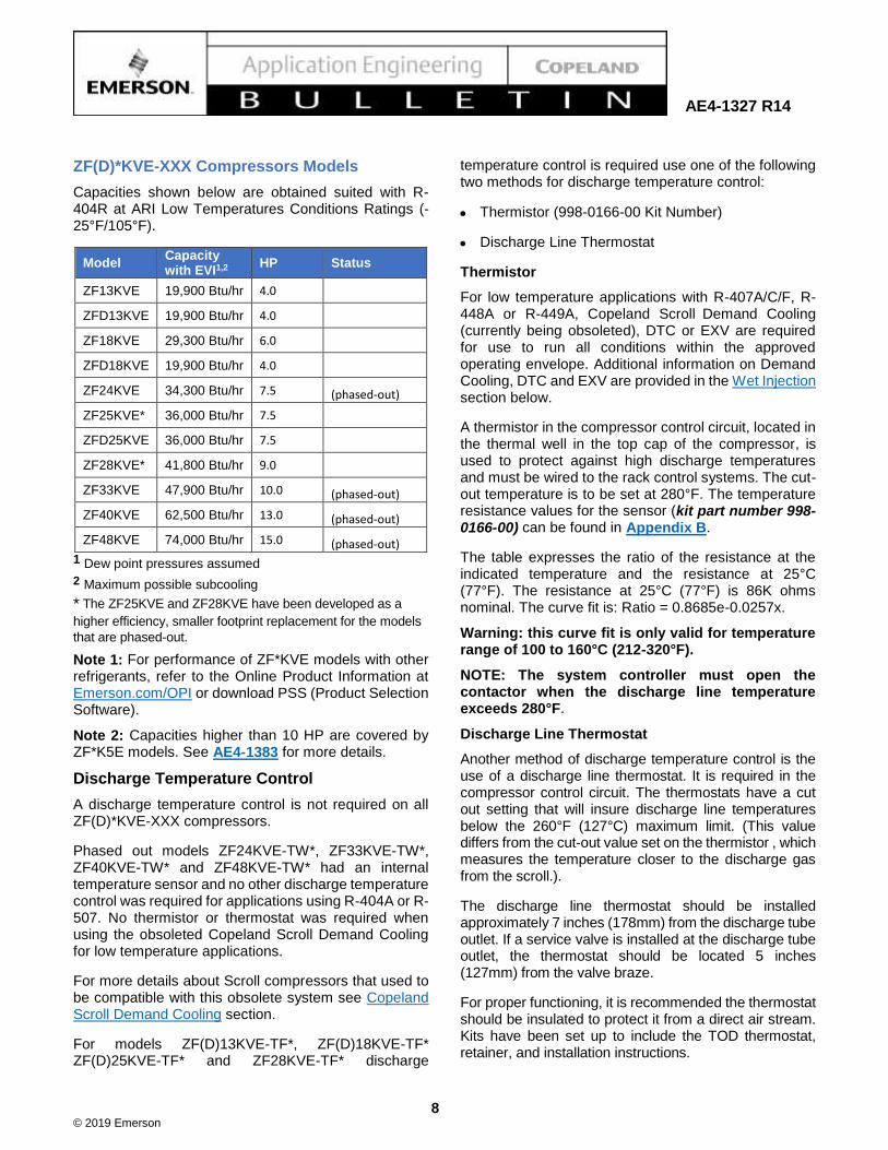
Heat Exchanger Sizing
Heat exchangers should be sized so that they have adequate design margin for the entire range of system operation, but they should be optimized for normal operating conditions. The parameters used to determine the proper heat exchanger size are described below:
• SIT = Heat Exchanger saturated evaporating temperature at its outlet pressure.
• LIT = Liquid in Temp ~ Condensing Outlet
• LOT = Liquid Out Temp = SIT+ TD
• VIT = Vapor In Temp ~ SIT + Loss
• VOT = Vapor Out Temp = SIT + Superheat
• H = Enthalpy
• HX Subcooling= (∆ Tsc) = LIT - LOT
• Superheat = TVO - TSI
• TD = LOT- SIT
• HX Btu/hr =Heat Exchanger Btu/hr Capacity
Note: See Figure 1 for reference of the Cycle for EVI.
Example of Heat Exchanger Sizing Optimized
ZF18KVE, R404A
Step 1
• Known Conditions -25°/105°/0°/65°
Te/Tc/Cond. SC/Suct.RG
Step 2
• Determine Flow Mo 355 lb/hr
From Product Data
Step 3
• Estimate SIT from Guideline 12°
Step 4
• Use the 10° Guideline To Derive
• LIT = TO-10°=105°-10°= 95°
• LOT=TSI +10° 22°
• HX SC= ∆ Tsc = TLI -TLO= 73°
= (TO –TSI - 20°)
• From R-404A Saturation Properties-Temp. Table:
❖ LIT =95° → Hft =47.0
❖ LOT =22° → Hlot =20.1
• HX Btu/hr = Mo x(Hft – Hlot)= 9550 Btu/hr
= 355 x (47.0 – 20.1)
Example of Heat Exchanger Sizing Fixed Liquid Temperature ZF18KVE, R404A
Step 1
• Known Conditions -25°/105°/0°/65°
Te/Tc/Cond. SC/Suct.RG
Step 2
• Determine Flow Mo 355 lb/hr
From Product Data
Step 3
• Use the 10° Guideline To Derive
• LIT = TO-10°=105°-10° 95°
• LOT, User Defined= 50°
• HX SC=∆ Tsc = LIT -LOT= 45°
• From R-404A Saturation Properties-Temp. Table:
❖ LIT =95° → Hft =47.0
❖ LOT =50° → Hlot =29.7
• HX Btu/hr = Mo x(Hft – Hlot)= 6140 Btu/hr
= 355 x (47.0 – 29.7)
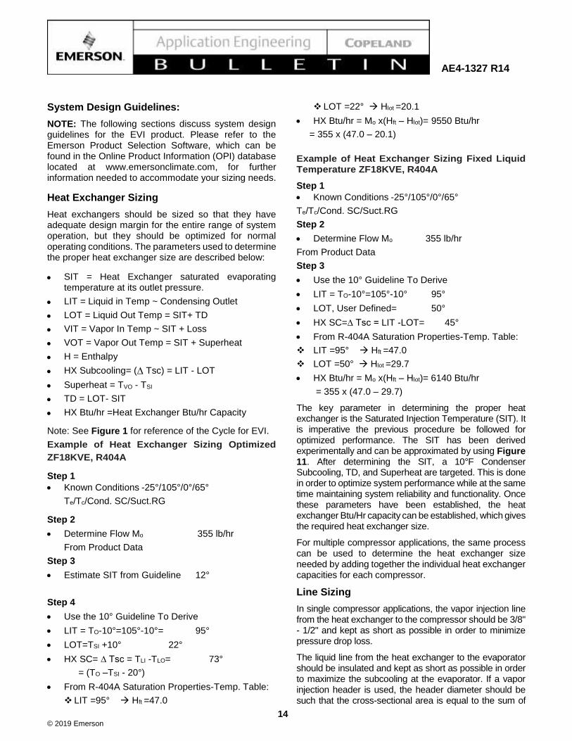
The key parameter in determining the proper heat exchanger is the Saturated Injection Temperature (SIT). It is imperative the previous procedure be followed for optimized performance. The SIT has been derived experimentally and can be approximated by using Figure 11. After determining the SIT, a 10°F Condenser Subcooling, TD, and Superheat are targeted. This is done in order to optimize system performance while at the same time maintaining system reliability and functionality. Once these parameters have been established, the heat exchanger Btu/Hr capacity can be established, which gives the required heat exchanger size.
For multiple compressor applications, the same process can be used to determine the heat exchanger size needed by adding together the individual heat exchanger capacities for each compressor.
Line Sizing
In single compressor applications, the vapor injection line from the heat exchanger to the compressor should be 3/8" - 1/2" and kept as short as possible in order to minimize pressure drop loss.
The liquid line from the heat exchanger to the evaporator should be insulated and kept as short as possible in order to maximize the subcooling at the evaporator. If a vapor injection header is used, the header diameter should be such that the cross-sectional area is equal to the sum of
© 2019 Emerson
15
AE4-1327 R14
the cross-sectional areas of the individual cross-sectional lines to the compressor.
For example, for four compressors, each with a 3/8" vapor injection line, the header tube diameter should be a 7/8" tube. In addition, the individual injection lines to the compressors should tap into the header either on top or on the sides of the header tube; a bottom tap will increase the risk of returning liquid into the compressor through the vapor injection line.
Available Rotalock to Stub Tube Adapter Kit: 998-0034-18
Description:
1” x 14 thread size to ½” Stub tube Sweat
Heat Exchanger TXV Sizing
TXV's should be sized so that they have adequate design margin for the entire range of system operation, but they should be optimized for normal operating conditions. Select a TXV that is able to handle the Btu/hr capacity of the heat exchanger determined in the section above.
Solenoid Valve & Ball Valve
A solenoid valve is required to stop the flow of vapor from the system to the compressor when the compressor is in the off cycle. This must be a vapor solenoid sized equivalent to or larger than the vapor injection tube size.
For minimum orifice sizes see Table 5. For service purposes, a mechanical ball valve (not provided by Emerson) is also recommended in the vapor injection line.
Figure 11 - Saturated Injection Temperature Graph

© 2019 Emerson
16
AE4-1327 R14
Table 4 Current Sensing Relay Kit
Model 24V 120V 240V Kits Include:
ZF13KV 985-1500-00 985-1500-01 985-1500-02
TXV,
Solenoid Valve,
Current Sensing
Relay, Heat
Exchanger
ZF18KV
ZF24KV N/A N/A N/A
ZF25KV 985-1500-00 985-1500-01 985-1500-02
ZF28KV
ZF33KV
N/A N/A N/A
ZF34K5
ZF40KV
ZF41K5
ZF48KV
ZF49K5
ZF54K5
Table 5 - Vapor Injection Solenoid Orifice Size
Model Minimum Orifice Size Flow Control Valve Series
ZF13KV 3/16" 200RB 3
ZF18KV
ZF24KV
1/4" 200RB 4
ZF25KV
ZF28KV
ZF33KV
ZF34K5
ZF40KV
5/16" 200RB 5 ZF41K5
ZF48KV
ZF49K5
ZF54K5 3/8” 200RB 6

© 2019 Emerson
17
AE4-1327 R14
Current Sensing Relay
To prevent the solenoid from remaining open during a ‘motor protector trip’ a current sensing relay must be provided that senses whenever the compressor is ‘OFF’
and closes the solenoid to stop injection. See Table 4 for a kit with the correct current sensing relay.
Multiple Compressor Applications
EVI can also be used in multiple compressor applications. Unlike a standard compressor system, the EVI compressor system changes its delivered capacity by changing the amount of sub-cooling provided at the sub-cooling heat exchanger. The result is that in high ambient temperature conditions (summer operation) and in low ambient temperature conditions (winter operation), the same number of compressors tend to run. It is important to note this since most personnel are used to seeing fewer compressors in operation in the cooler winter months compared to the hotter summer months; with EVI, almost the same number of compressors will be running in the summer and winter.
Multiple EVI compressors can be used with either a single heat exchanger for each compressor or a common heat exchanger for all compressors. In case of a common heat exchanger, a solenoid valve should be installed on each individual vapor injection line.
Special care has to be given to the design of the heat exchanger and of the thermostatic expansion valve (TXV) to allow for part load operation. Good refrigerant distribution is required in the common heat exchanger
as well as sufficient velocities for oil return, even at part load.
In the case of a large range of capacity modulation (more than 2 compressors in parallel), the use of an Electronic Expansion Valve (EXV) or of two different TXV(s) controlled by individual solenoid valves, may improve performance. For example, one at 100% full load and the second solenoid valve for 30% of full load. (See Figure 12 and Figure 13).
It is necessary to ensure that the solenoid valves, vapor injection lines and header(s) are adequately sized in order to keep pressure drop to a minimum. At the same time, the layout should be such that excessive amounts of oil do not accumulate in the header.
Controlling Liquid Out Temperature
The Liquid Out Temperatures (LOT) will typically be determined by the operating condition of the compressor. If the LOT needs to be fixed at any specific value (for example, 50°F) for purposes of good system control, an Evaporator Pressure Regulator (EPR) valve may be introduced at the vapor outlet of the subcooling heat exchanger. Table 6 shows approximate EPR settings for different
liquid temperature.
Emerson Product Selection Software can be used to determine the effect of fixing LOT on the capacity and efficiency of the compressor. See Figure 14 and Figure 15.
Figure 12 - EVI Paralleling with HW Thermostatic Valves of Different Capacity
Figure 13 - EVI Paralleling with HW Electronic Expansion Valve (EXV)

© 2019 Emerson
18
AE4-1327 R14
General Guidelines and More Information
For general Copeland Scroll compressor please log in to Online Product Information at Emerson.com/OPI, refer to the Application Engineering bulletins listed below, or contact your Application Engineer.
AE4-1383 Application Guidelines for ZF*K5E & ZB*K5E Copeland Scroll™ K5 Compressors for Refrigeration 8-17 HP with CoreSense™ Diagnostics
AE4-1299 Application Guidelines for K4 Refrigeration Copeland Scroll™ Compressors 2 - 9 Horsepower
AE8-1328 Copeland™ Digital Compressor Controller
Table 6- Approximate EPR Settings
R-407A/C/F, R-448A and R-449A
(Based on Dew Point Properties)
R-404A
(Based on Dew Point Properties)
Subcooler Liquid Out
Temperature, F
Approximate EPR
Setting, psig (psia)
60 86.1 (100.8) 103.6 (118.3)
50 69.4 (84.1) 85.4 (100.1)
40 54.8 (69.5) 69.3 (84.0)
NOTE: Assumes a 10°F DT across EVI Heat Exchanger

© 2019 Emerson
19
AE4-1327 R14
Figure 14 - Screenshot of Emerson’s Product Selection Software Showing the Maximum Subcooling Obtained When the Default ‘Automatic’ is Selected for Economizer Settings
Figure 15 - Screenshot of the Product Selection Software Showing the Constant Liquid Temperature at Outset of the Subcooling Heat Exchanger

© 2019 Emerson
20
AE4-1327 R14
Figure 16 - Medium Temperature ZF**KVE Envelope (R-404A/R-507)
* For ZF25KVE and ZF28KVE operating envelope see Figure 20
Figure 17 - Low Temperature ZF**KVE and ZF**K5E Envelope (R-404A/R-507)

© 2019 Emerson
21
AE4-1327 R14
Figure 18 - Medium Temperature ZF**KVE Envelope (R-407A/C/F, R-448A and R-449A)
* For ZF25KVE and ZF28KVE see Figure 20 for operating envelope.
Figure 19 - Low Temperature ZF**KVE Envelope (R-407A/C/F, R-448A and R-449A) Condition: 65°F Return Gas, 260°F Max DLT

© 2019 Emerson
22
AE4-1327 R14
07A/C/F, R-448A and R-449A) Figure 20 - ZF*K5E (Excluding ZF49K5E), ZF25KVE
Medium Temperature Operating Map with and without Vapor Injection
Figure 21 - ZF*K5E Low Temperature Vapor Injection Operating Map (65°F Return Gas)

© 2019 Emerson
23
AE4-1327 R14
Figure 22 - Low Temperature Vapor Injection** Operation Map
(65°F Return Gas)
The contents of this publication are presented for informational purposes only and are not to be construed as warranties or guarantees, express or implied, regarding
the products or services described herein or their use or applicability. Emerson Climate Technologies, Inc. and/or its affiliates (collectively "Emerson"), as applicable,
reserve the right to modify the design or specifications of such products at any time without notice. Emerson does not assume responsibility for the selection, use or
maintenance of any product. Responsibility for proper selection, use and maintenance of any Emerson product remains solely with the purchaser or end user.

© 2019 Emerson
24
AE4-1327 R14
Appendix A: Service Section: Copeland Scroll Demand Cooling for ZF*KVE Models.
Introduction
The Demand Cooling for Scroll Compressors is obsolete and being replaced with a DTC valve. Please check your local distributor for inventory.
This Demand Cooling section is included only for service purposes.
Demand Cooling uses electronics to provide a reliable cost-effective solution to high internal discharge temperatures encountered in low temperature applications using R-407A/C/F or R448A & R449A. Demand Cooling had traditionally been applied to the Copeland Discus™ product line to control high internal discharge temperatures that exceed the safe temperature limit for long term stability of refrigeration oil. Emerson Climate Technologies approved the use of Demand Cooling for the Copeland Scroll Economized Vapor Injection (EVI) product line using low temperature R-407A/C/F, R-448A or R-449A. The integration of Demand Cooling with EVI scroll creates a 'wet-injection' approach to discharge temperature control. Emerson approved the following EVI scrolls for use in low temperature applications with Demand Cooling:
ZF(D)13KVE ZF(D)18KVE ZF(D)25KVE ZF28KVE ZF33KVE ZF24KVE ZF40KVE The Demand Cooling module uses the signal of a discharge line temperature sensor to monitor discharge gas temperature. If a critical temperature is reached, the module energizes a long life injection valve which meters a controlled amount of saturated refrigerant into the vapor injection line. The injection will continue until the discharge line temperature reaches a lower preset temperature. This process controls the discharge temperature to a safe level. If, for some reason, the discharge temperature rises above a preset maximum level, the Demand Cooling module will turn the compressor off (requiring a manual reset) and actuate its alarm contact.
The injection valve orifice has been carefully chosen to be large enough to provide the necessary cooling when required but not so large that a dangerous amount of liquid is injected, or that excessive system pressure fluctuation occurs during injection valve cycling. It is important to use the correct valve for the EVI scroll.
Performance data for Demand Cooling compressors includes the effects of injection when it is required. The approximate conditions where injection occurs are shown in Figure 19 for R-407A/C/F, R-407F, R-448A or
R-449A. At the conditions where Demand Cooling is operating, the performance values are time averages of the instantaneous values, since small fluctuations occur as the Demand Cooling injection valve cycles.
The Demand Cooling system addresses the capacity and efficiency issues by limiting injection to those times when it is required to control discharge temperatures to safe levels. For most applications, this will only be during periods of high condensing temperatures, high return gas temperatures, or abnormally low suction pressure. The Demand Cooling system has been designed to meet the same high reliability standards as Scroll compressors.
Demand Cooling™ System Design for Low Temp. Compressors Models (Obsolete and replaced with DTC or EXV injection)
When Demand Cooling operates, it “diverts” refrigeration capacity in the form of injected saturated refrigerant from the vapor injection circuit to the compressor (See Figure 23 or a typical single system schematic). Demand Cooling injects a small amount of liquid to the vapor injection stream to cool the discharge. This does not affect the mass flow significantly. However, when the valve injects the system will lose some capacity because the EVI pressure increases and thus decreases EVI performance.
Note! A separate Demand Cooling kit is required for each compressor.
The Demand cooling temperature sensor should be located close to the compressor to ensure an accurate discharge temperature reading. The optimal location is between 5 and 7 inches from the compressor on the discharge line (Figure 23).
The injection valve should be installed as close as possible to the compressor vapor injection inlet, no more than 3 feet. The line MUST be well insulated. If there is substantial heat gain along the vapor injection line, injection may result in a substantial loss in vapor injection capacity during Demand Cooling operation. In order to minimize this loss, good practice indicates Demand Cooling operation be kept to a minimum through proper system design and installation practices. There are three areas which can be addressed to minimize the impact of Demand Cooling operation on performance:
1. Compressor Return Gas Temperature: Suction lines should be well insulated to reduce suction line heat gain. Return gas superheat should be as low

© 2019 Emerson
25
AE4-1327 R14
as possible consistent with safe compressor operation.
2. Condensing Temperatures: It is important when using R-407A/C/F, R-448A or R-449A as a low temperature refrigerant that condensing temperatures be minimized to reduce compression ratios and compressor discharge temperature.
3. Suction pressure: Evaporator design and system control settings should provide the maximum suction pressure consistent with the application in order to have as low a compression ratio as possible.
Demand Cooling with Copeland™ Digital Compressor Controller
In order to control a ZFD*KVE Copeland Scroll Digital ™ compressor (not required on ZFD*K5E models), the Copeland Digital Compressor Controller (IDCM, P/N 943-0086-00) may be used in multiple compressor applications. This digital compressor controller has its own discharge temperature protection. However, for applications using Demand Cooling, the Demand Cooling module should have primary control of the temperature protection. To ensure the Demand Cooling system functions appropriately, jumper the
T1 and T2 inputs on the Copeland Digital Compressor Controller, with a 5kOhm, 1 Watt resistor. See Figure 25 for more detail.
For more details about IDCM refer to AE8-1328 Bulletin.
Demand Cooling System Components
The Demand Cooling system consists of: the discharge line temperature sensor, the Demand Cooling module, and the injection valve solenoid.
Demand Cooling Specifications
Demand Cooling is designed to operate and protect the compressor within the evaporating and condensing envelope identified in Figure 19. Operating set-points and control actions are listed in Table 7.
Demand Cooling Wiring Schematic
Figure 24 shows a recommended wiring schematic for the Demand Cooling assembly.
The normally closed (NC) contact of the alarm relay (L-M) should be wired in the compressor contactor control circuit so that opening this contact removes the compressor from the line and removes power to the CM.
Figure 23 - Typical Single Compressor System Schematic with obsolete Demand Cooling System (only for
service purposes)

© 2019 Emerson
26
AE4-1327 R14
Figure 24 - Demand Cooling Module Wiring Diagram (Obsolete, only for service purpose)
Figure 25 - IDCM: Digital module Digital Compressor Controller Wiring Diagram
Note: IDCM doesn’t require any connection to DTC components.

© 2019 Emerson
27
AE4-1327 R14
Table 7 - Demand Cooling Operating Setpoints and Control Actions
Discharge Line Temperature
Demand Cooling Module Operation
Approximate Sensor Resistance
Rising Through 258°F Demand Cooling Solenoid ON 3,820
Falling Through 237°F Demand Cooling Solenoid OFF 5,000
Rising Through 286°F Alarm Contact Energized 2,620
At Room Temp (77°F) Demand Cooling Solenoid OFF 86,000
(when compressor has cooled)
Note: Demand Cooling for Scroll is obsolete. Table for Reference and for service only.

© 2019 Emerson
28
AE4-1327 R14
Appendix B: Temperature resistance values for sensor kit part number 998-0166-00
Temp. Coefficient °C
Temp Ratio Temp Ratio Temp Ratio Temp Ratio Temp Ratio Temp Ratio
-40°C 33.6 -1°C 3.4367 38°C 0.5774 77°C 0.1385 116°C 0.04372 155°C 0.0162
-39°C 31.449 0°C 3.2654 39°C 0.5546 78°C 0.134 117°C 0.04248 156°C 0.01584
-38°C 29.452 1°C 3.103 40°C 0.5327 79°C 0.1297 118°C 0.04128 157°C 0.01549
-37°C 27.597 2°C 2.9498 41°C 0.5117 80°C 0.1255 119°C 0.04012 158°C 0.01515
-36°C 25.873 3°C 2.8052 42°C 0.4918 81°C 0.1215 120°C 0.039 159°C 0.01482
-35°C 24.27 4°C 2.6686 43°C 0.4727 82°C 0.1177 121°C 0.03793 160°C 0.0145
-34°C 22.761 5°C 2.5396 44°C 0.4544 83°C 0.114 122°C 0.0369 161°C 0.01418
-33°C 21.357 6°C 2.4171 45°C 0.437 84°C 0.1104 123°C 0.0359 162°C 0.01388
-32°C 20.051 7°C 2.3013 46°C 0.4203 85°C 0.107 124°C 0.03494 163°C 0.01358
-31°C 18.834 8°C 2.1918 47°C 0.4042 86°C 0.1037 125°C 0.034 164°C 0.01328
-30°C 17.7 9°C 2.0883 48°C 0.3889 87°C 0.1005 126°C 0.03315 165°C 0.013
-29°C 16.6342 10°C 1.9903 49°C 0.3743 88°C 0.0974 127°C 0.03233 166°C 0.01275
-28°C 15.6404 11°C 1.8972 50°C 0.3603 89°C 0.0944 128°C 0.03153 167°C 0.0125
-27°C 14.7134 12°C 1.809 51°C 0.3469 90°C 0.0915 129°C 0.03075 168°C 0.01226
-26°C 13.8482 13°C 1.7255 52°C 0.334 91°C 0.08885 130°C 0.03 169°C 0.01203
-25°C 13.0402 14°C 1.6464 53°C 0.3217 92°C 0.0861 131°C 0.02926 170°C 0.0118
-24°C 12.2807 15°C 1.5714 54°C 0.3099 93°C 0.08355 132°C 0.02854 171°C 0.01157
-23°C 11.571 16°C 1.5 55°C 0.2986 94°C 0.08108 133°C 0.02784 172°C 0.01134
-22°C 10.9075 17°C 1.4323 56°C 0.2878 95°C 0.0787 134°C 0.02716 173°C 0.01112
-21°C 10.2868 18°C 1.3681 57°C 0.2774 96°C 0.07641 135°C 0.0265 174°C 0.01091
-20°C 9.706 19°C 1.3071 58°C 0.2675 97°C 0.0742 136°C 0.02586 175°C 0.017
-19°C 9.1588 20°C 1.2493 59°C 0.2579 98°C 0.07206 137°C 0.02525 176°C 0.01049
-18°C 8.6463 21°C 1.1942 60°C 0.2488 99°C 0.07 138°C 0.02465 177°C 0.01029
-17°C 8.1662 22°C 1.1418 61°C 0.24 100°C 0.068 139°C 0.02407 178°C 0.1009
-16°C 7.7162 23°C 1.0921 62°C 0.2315 101°C 0.06612 140°C 0.0235 179°C 0.00989
-15°C 8.294 24°C 1.0449 63°C 0.2235 102°C 0.0643 141°C 0.02295 180°C 0.0097
-14°C 6.8957 25°C 1 64°C 0.2157 103°C 0.06255 142°C 0.02242 181°C 0.00949
-13°C 6.5219 26°C 0.9571 65°C 0.2083 104°C 0.06085 143°C 0.0219 182°C 0.00928
-12°C 6.1711 27°C 0.9164 66°C 0.2011 105°C 0.0592 144°C 0.02139 183°C 0.00908
-11°C 5.8415 28°C 0.8776 67°C 0.1943 106°C 0.0576 145°C 0.0209 184°C 0.00889
-10°C 5.5319 29°C 0.8407 68°C 0.1876 107°C 0.05605 146°C 0.02039 185°C 0.0087
-9°C 5.2392 30°C 0.8056 69°C 0.1813 108°C 0.05456 147°C 0.0199 186°C 0.00853
-8°C 4.964 31°C 0.772 70°C 0.1752 109°C 0.0531 148°C 0.01942 187°C 0.00837
-7°C 4.7052 32°C 0.7401 71°C 0.1693 110°C 0.0517 149°C 0.01895 188°C 0.00821
-6°C 4.4617 33°C 0.7096 72°C 0.1637 111°C 0.05027 150°C 0.0185 189°C 0.00805
-5°C 4.2324 34°C 0.6806 73°C 0.1582 112°C 0.04889 151°C 0.01801 190°C 0.0079
-4°C 4.0153 35°C 0.653 74°C 0.153 113°C 0.04755 152°C 0.01754
-3°C 3.8109 36°C 0.6266 75°C 0.148 114°C 0.04625 153°C 0.01708
-2°C 3.6182 37°C 0.6014 76°C 0.1431 115°C 0.045 154°C 0.01663

© 2019 Emerson
29
AE4-1327 R14
Temp. Coefficient °F
Temp Ratio Temp Ratio Temp Ratio Temp Ratio Temp Ratio Temp Ratio
-40.0 °F 33.6 30.2 °F 3.4367 100.4 °F 0.5774 170.6 °F 0.1385 240.8 °F 0.04372 311.0 °F 0.0162
-38.2 °F 31.449 32.0 °F 3.2654 102.2 °F 0.5546 172.4 °F 0.134 242.6 °F 0.04248 312.8 °F 0.01584
-36.4 °F 29.452 33.8 °F 3.103 104.0 °F 0.5327 174.2 °F 0.1297 244.4 °F 0.04128 314.6 °F 0.01549
-34.6 °F 27.597 35.6 °F 2.9498 105.8 °F 0.5117 176.0 °F 0.1255 246.2 °F 0.04012 316.4 °F 0.01515
-32.8 °F 25.873 37.4 °F 2.8052 107.6 °F 0.4918 177.8 °F 0.1215 248.0 °F 0.039 318.2 °F 0.01482
-31.0 °F 24.27 39.2 °F 2.6686 109.4 °F 0.4727 179.6 °F 0.1177 249.8 °F 0.03793 320.0 °F 0.0145
-29.2 °F 22.761 41.0 °F 2.5396 111.2 °F 0.4544 181.4 °F 0.114 251.6 °F 0.0369 321.8 °F 0.01418
-27.4 °F 21.357 42.8 °F 2.4171 113.0 °F 0.437 183.2 °F 0.1104 253.4 °F 0.0359 323.6 °F 0.01388
-25.6 °F 20.051 44.6 °F 2.3013 114.8 °F 0.4203 185.0 °F 0.107 255.2 °F 0.03494 325.4 °F 0.01358
-23.8 °F 18.834 46.4 °F 2.1918 116.6 °F 0.4042 186.8 °F 0.1037 257.0 °F 0.034 327.2 °F 0.01328
-22.0 °F 17.7 48.2 °F 2.0883 118.4 °F 0.3889 188.6 °F 0.1005 258.8 °F 0.03315 329.0 °F 0.013
-20.2 °F 16.6342 50.0 °F 1.9903 120.2 °F 0.3743 190.4 °F 0.0974 260.6 °F 0.03233 330.8 °F 0.01275
-18.4 °F 15.6404 51.8 °F 1.8972 122.0 °F 0.3603 192.2 °F 0.0944 262.4 °F 0.03153 332.6 °F 0.0125
-16.6 °F 14.7134 53.6 °F 1.809 123.8 °F 0.3469 194.0 °F 0.0915 264.2 °F 0.03075 334.4 °F 0.01226
-14.8 °F 13.8482 55.4 °F 1.7255 125.6 °F 0.334 195.8 °F 0.08885 266.0 °F 0.03 336.2 °F 0.01203
-13.0 °F 13.0402 57.2 °F 1.6464 127.4 °F 0.3217 197.6 °F 0.0861 267.8 °F 0.02926 338.0 °F 0.0118
-11.2 °F 12.2807 59.0 °F 1.5714 129.2 °F 0.3099 199.4 °F 0.08355 269.6 °F 0.02854 339.8 °F 0.01157
-9.4 °F 11.571 60.8 °F 1.5 131.0 °F 0.2986 201.2 °F 0.08108 271.4 °F 0.02784 341.6 °F 0.01134
-7.6 °F 10.9075 62.6 °F 1.4323 132.8 °F 0.2878 203.0 °F 0.0787 273.2 °F 0.02716 343.4 °F 0.01112
-5.8 °F 10.2868 64.4 °F 1.3681 134.6 °F 0.2774 204.8 °F 0.07641 275.0 °F 0.0265 345.2 °F 0.01091
-4.0 °F 9.706 66.2 °F 1.3071 136.4 °F 0.2675 206.6 °F 0.0742 276.8 °F 0.02586 347.0 °F 0.017
-2.2 °F 9.1588 68.0 °F 1.2493 138.2 °F 0.2579 208.4 °F 0.07206 278.6 °F 0.02525 348.8 °F 0.01049
-0.4 °F 8.6463 69.8 °F 1.1942 140.0 °F 0.2488 210.2 °F 0.07 280.4 °F 0.02465 350.6 °F 0.01029
1.4 °F 8.1662 71.6 °F 1.1418 141.8 °F 0.24 212.0 °F 0.068 282.2 °F 0.02407 352.4 °F 0.1009
3.2 °F 7.7162 73.4 °F 1.0921 143.6 °F 0.2315 213.8 °F 0.06612 284.0 °F 0.0235 354.2 °F 0.00989
5.0 °F 8.294 75.2 °F 1.0449 145.4 °F 0.2235 215.6 °F 0.0643 285.8 °F 0.02295 356.0 °F 0.0097
6.8 °F 6.8957 77.0 °F 1 147.2 °F 0.2157 217.4 °F 0.06255 287.6 °F 0.02242 357.8 °F 0.00949
8.6 °F 6.5219 78.8 °F 0.9571 149.0 °F 0.2083 219.2 °F 0.06085 289.4 °F 0.0219 359.6 °F 0.00928
10.4 °F 6.1711 80.6 °F 0.9164 150.8 °F 0.2011 221.0 °F 0.0592 291.2 °F 0.02139 361.4 °F 0.00908
12.2 °F 5.8415 82.4 °F 0.8776 152.6 °F 0.1943 222.8 °F 0.0576 293.0 °F 0.0209 363.2 °F 0.00889
14.0 °F 5.5319 84.2 °F 0.8407 154.4 °F 0.1876 224.6 °F 0.05605 294.8 °F 0.02039 365.0 °F 0.0087
15.8 °F 5.2392 86.0 °F 0.8056 156.2 °F 0.1813 226.4 °F 0.05456 296.6 °F 0.0199 366.8 °F 0.00853
17.6 °F 4.964 87.8 °F 0.772 158.0 °F 0.1752 228.2 °F 0.0531 298.4 °F 0.01942 368.6 °F 0.00837
19.4 °F 4.7052 89.6 °F 0.7401 159.8 °F 0.1693 230.0 °F 0.0517 300.2 °F 0.01895 370.4 °F 0.00821
21.2 °F 4.4617 91.4 °F 0.7096 161.6 °F 0.1637 231.8 °F 0.05027 302.0 °F 0.0185 372.2 °F 0.00805
23.0 °F 4.2324 93.2 °F 0.6806 163.4 °F 0.1582 233.6 °F 0.04889 303.8 °F 0.01801 374.0 °F 0.0079
24.8 °F 4.0153 95.0 °F 0.653 165.2 °F 0.153 235.4 °F 0.04755 305.6 °F 0.01754
26.6 °F 3.8109 96.8 °F 0.6266 167.0 °F 0.148 237.2 °F 0.04625 307.4 °F 0.01708
28.4 °F 3.6182 98.6 °F 0.6014 168.8 °F 0.1431 239.0 °F 0.045 309.2 °F 0.01663