AE Analysis on Blade Cutting Pressure Adjustment in ... · AE ANALYSIS ON BLADE CUTTING PRESSURE...
13
J. Acoustic Emission, 27 (2009) 64 © 2009 Acoustic Emission Group AE ANALYSIS ON BLADE CUTTING PRESSURE ADJUSTMENT IN DYNAMIC CUTTING OF PAPERBOARD DARULIHSAN A. HAMID 1 , SHIGERU NAGASAWA 1 , YASUSHI FUKUZAWA 1 , YUUKI KOMIYAMA 1 and AKIRA HINE 2 1) Department of Mechanical Engineering, Nagaoka University of Technology, 1603-1 Kami- tomioka, Nagaoka, Niigata 940-2188, Japan; 2) Katayama Steel Rule Die Inc., 3-7 Higashigoken, Shinjuku, Tokyo 162-0813, Japan Abstract A method for cutting-blade pressure adjustment during dynamic cutting of paperboard is in- troduced in a combination of resin bridgeless die and high-carbon center-bevel blade. In this method, the blade bottom is embedded in a dead-end bridgeless die slot where unbalance of blade cutting will be compensated from the sinking of the blade bottom. This paper reports on the relationship between the acoustic emission (AE) and blade-cutting pressure balance in a crank machine under quasi-static reciprocal motion. Two kinds of blade bottom condition with bottom thickness of 0.71 mm were experimented and their results on force difference and AE signals during cutting were compared. Through this research, the proposed measurement tech- nique was found reliable in detecting the characteristics of blade-pressure adjustment, and the correlation between the AE signal amplitude, the frequency spectrum and the blade shimming condition. Keywords: Paperboard cutting, Pressure balance, Tool collision, Blade crushing, Self-shimming Introduction Problems that occur on the cutting tip of a blade during paperboard cutting inevitably affect the quality of a wedged sheet [1, 2]. One of them is an early damage of the cutting-tip profile, resulting in differences of blade height. In order to prevent this problem, several methods of pressure-misalignment reduction on the cutting blade were considered and empirically trialed. Grebe [3] considered a double-structure blade with a hardened cutting tip and a soft bottom tip. The basic principle of this blade is the soft bottom tip will plastically deform more readily than the cutting tip at a certain exerted cutting forces. Namely, the soft bottom tip plays the role of a relief element in order to avoid an excessive crushing of the cutting tip. For examining the deformation behavior of the cutting tip of blades, Darulihsan et al. has studied the fundamental mechanics of a 16°-center-bevel bottom blade subjected to a pushing load [4, 5]. For the supplemental use of cushion sheets, a mild resin sheet or a rubber underlay was inserted behind the counter plate or the cutting-die board [6]. Figure 1 illustrates a concep- tual adjusting method by using a shimming sheet on a blade bottom. Nagae et al. studied the ef- fect of sinking characteristics of a mild resin die board for compensating the eccentricity of the cutting tip [7, 8]. This was named as the bridgeless die. In this type of die board, the cutting-die board and the shimming sheet were combined in a block unit and hence no bridge was required for imbedding the cutting blade. In that study, a certain depth of dead-end slot was made in the resin plate where a cutting blade was inserted. When a certain value of force was applied to the cutting tip of a blade, the blade bottom sunk into the resin plate. The sinking of blade bottom re- sulted in the cutting-tip force balance but this sinking speed is totally dependent
Transcript of AE Analysis on Blade Cutting Pressure Adjustment in ... · AE ANALYSIS ON BLADE CUTTING PRESSURE...

J. Acoustic Emission, 27 (2009) 64 © 2009 Acoustic Emission Group
AE ANALYSIS ON BLADE CUTTING PRESSURE ADJUSTMENT IN DYNAMIC CUTTING OF PAPERBOARD
DARULIHSAN A. HAMID1, SHIGERU NAGASAWA1, YASUSHI FUKUZAWA1,
YUUKI KOMIYAMA1 and AKIRA HINE2
1) Department of Mechanical Engineering, Nagaoka University of Technology, 1603-1 Kami-tomioka, Nagaoka, Niigata 940-2188, Japan; 2) Katayama Steel Rule Die Inc., 3-7 Higashigoken, Shinjuku, Tokyo 162-0813, Japan Abstract A method for cutting-blade pressure adjustment during dynamic cutting of paperboard is in-troduced in a combination of resin bridgeless die and high-carbon center-bevel blade. In this method, the blade bottom is embedded in a dead-end bridgeless die slot where unbalance of blade cutting will be compensated from the sinking of the blade bottom. This paper reports on the relationship between the acoustic emission (AE) and blade-cutting pressure balance in a crank machine under quasi-static reciprocal motion. Two kinds of blade bottom condition with bottom thickness of 0.71 mm were experimented and their results on force difference and AE signals during cutting were compared. Through this research, the proposed measurement tech-nique was found reliable in detecting the characteristics of blade-pressure adjustment, and the correlation between the AE signal amplitude, the frequency spectrum and the blade shimming condition.
Keywords: Paperboard cutting, Pressure balance, Tool collision, Blade crushing, Self-shimming Introduction
Problems that occur on the cutting tip of a blade during paperboard cutting inevitably affect the quality of a wedged sheet [1, 2]. One of them is an early damage of the cutting-tip profile, resulting in differences of blade height. In order to prevent this problem, several methods of pressure-misalignment reduction on the cutting blade were considered and empirically trialed. Grebe [3] considered a double-structure blade with a hardened cutting tip and a soft bottom tip. The basic principle of this blade is the soft bottom tip will plastically deform more readily than the cutting tip at a certain exerted cutting forces. Namely, the soft bottom tip plays the role of a relief element in order to avoid an excessive crushing of the cutting tip.
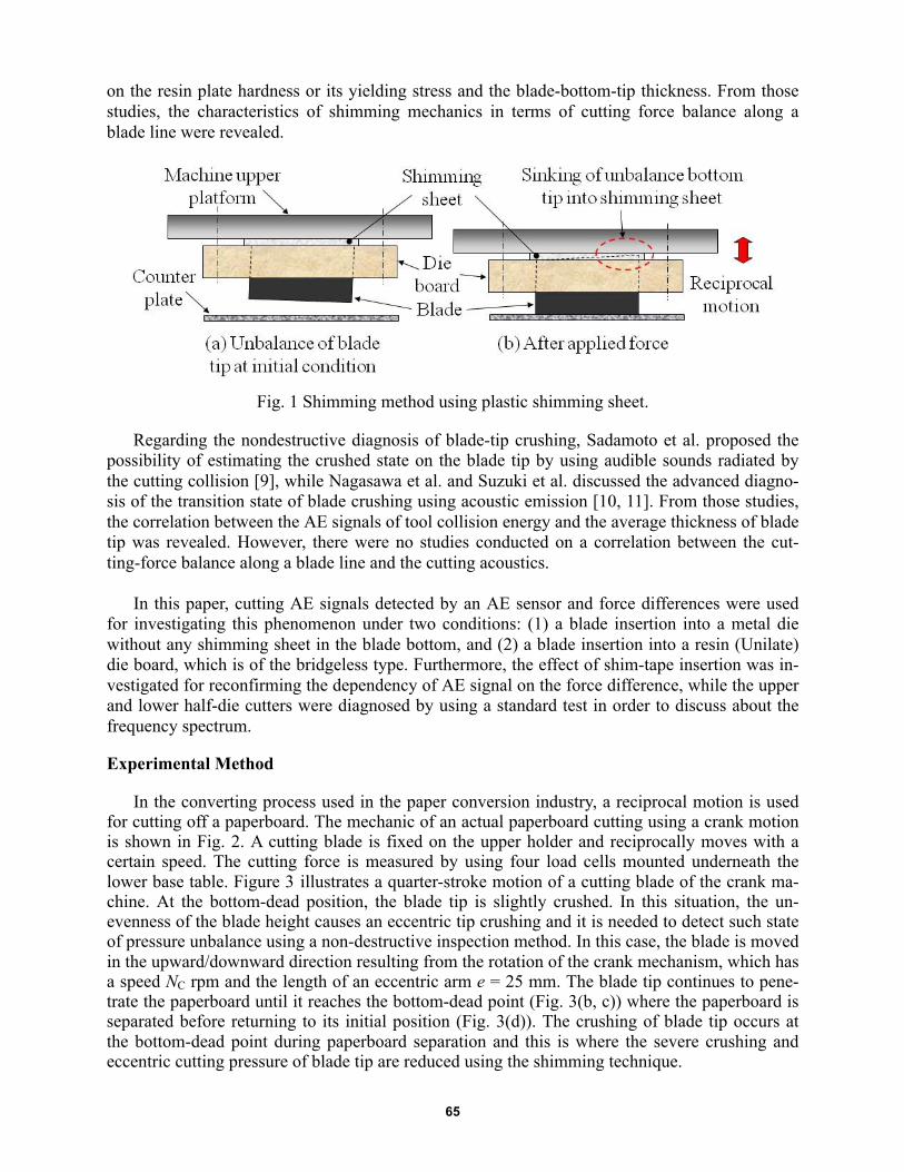
For examining the deformation behavior of the cutting tip of blades, Darulihsan et al. has studied the fundamental mechanics of a 16°-center-bevel bottom blade subjected to a pushing load [4, 5]. For the supplemental use of cushion sheets, a mild resin sheet or a rubber underlay was inserted behind the counter plate or the cutting-die board [6]. Figure 1 illustrates a concep-tual adjusting method by using a shimming sheet on a blade bottom. Nagae et al. studied the ef-fect of sinking characteristics of a mild resin die board for compensating the eccentricity of the cutting tip [7, 8]. This was named as the bridgeless die. In this type of die board, the cutting-die board and the shimming sheet were combined in a block unit and hence no bridge was required for imbedding the cutting blade. In that study, a certain depth of dead-end slot was made in the resin plate where a cutting blade was inserted. When a certain value of force was applied to the cutting tip of a blade, the blade bottom sunk into the resin plate. The sinking of blade bottom re-sulted in the cutting-tip force balance but this sinking speed is totally dependent
65
on the resin plate hardness or its yielding stress and the blade-bottom-tip thickness. From those studies, the characteristics of shimming mechanics in terms of cutting force balance along a blade line were revealed.
Fig. 1 Shimming method using plastic shimming sheet.
Regarding the nondestructive diagnosis of blade-tip crushing, Sadamoto et al. proposed the possibility of estimating the crushed state on the blade tip by using audible sounds radiated by the cutting collision [9], while Nagasawa et al. and Suzuki et al. discussed the advanced diagno-sis of the transition state of blade crushing using acoustic emission [10, 11]. From those studies, the correlation between the AE signals of tool collision energy and the average thickness of blade tip was revealed. However, there were no studies conducted on a correlation between the cut-ting-force balance along a blade line and the cutting acoustics.
In this paper, cutting AE signals detected by an AE sensor and force differences were used for investigating this phenomenon under two conditions: (1) a blade insertion into a metal die without any shimming sheet in the blade bottom, and (2) a blade insertion into a resin (Unilate) die board, which is of the bridgeless type. Furthermore, the effect of shim-tape insertion was in-vestigated for reconfirming the dependency of AE signal on the force difference, while the upper and lower half-die cutters were diagnosed by using a standard test in order to discuss about the frequency spectrum.
Experimental Method
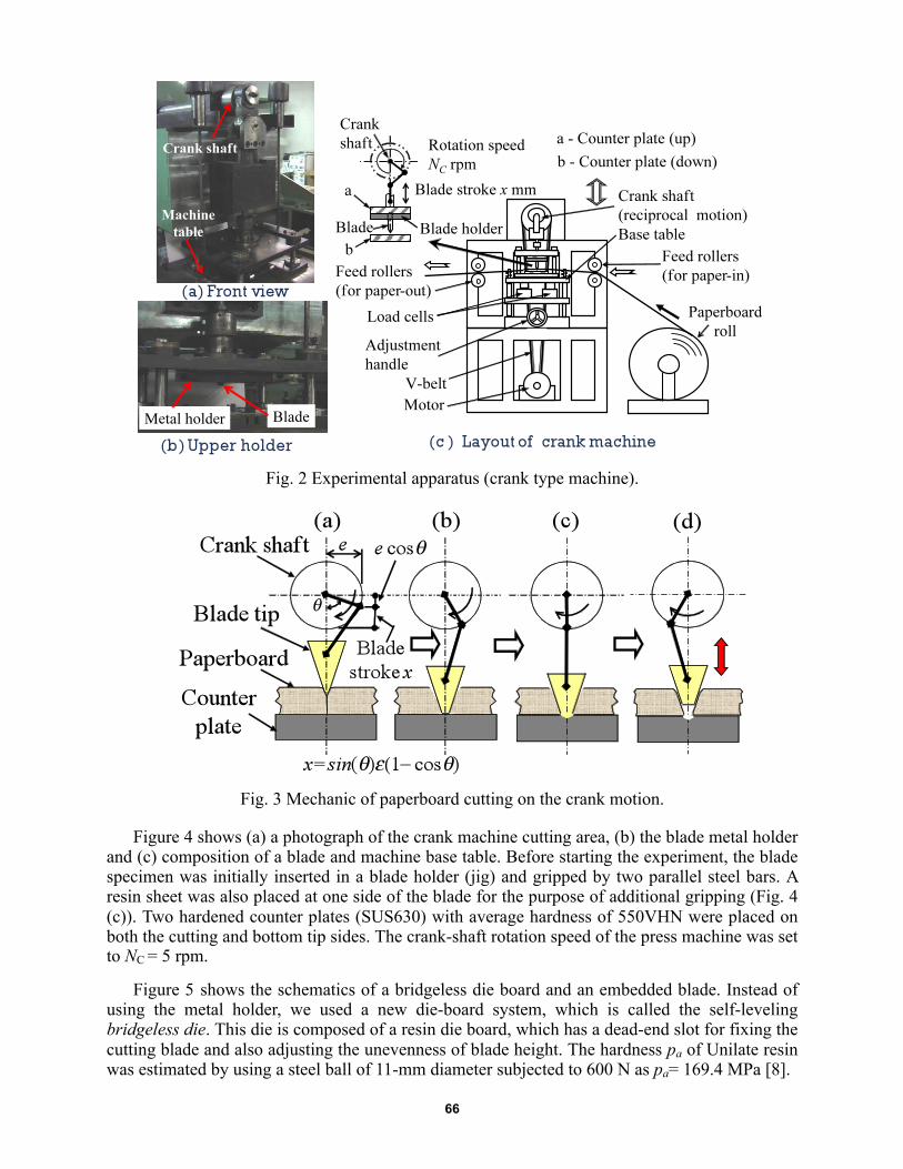
In the converting process used in the paper conversion industry, a reciprocal motion is used for cutting off a paperboard. The mechanic of an actual paperboard cutting using a crank motion is shown in Fig. 2. A cutting blade is fixed on the upper holder and reciprocally moves with a certain speed. The cutting force is measured by using four load cells mounted underneath the lower base table. Figure 3 illustrates a quarter-stroke motion of a cutting blade of the crank ma-chine. At the bottom-dead position, the blade tip is slightly crushed. In this situation, the un-evenness of the blade height causes an eccentric tip crushing and it is needed to detect such state of pressure unbalance using a non-destructive inspection method. In this case, the blade is moved in the upward/downward direction resulting from the rotation of the crank mechanism, which has a speed NC rpm and the length of an eccentric arm e = 25 mm. The blade tip continues to pene-trate the paperboard until it reaches the bottom-dead point (Fig. 3(b, c)) where the paperboard is separated before returning to its initial position (Fig. 3(d)). The crushing of blade tip occurs at the bottom-dead point during paperboard separation and this is where the severe crushing and eccentric cutting pressure of blade tip are reduced using the shimming technique.
66
Fig. 2 Experimental apparatus (crank type machine).
Fig. 3 Mechanic of paperboard cutting on the crank motion.
Figure 4 shows (a) a photograph of the crank machine cutting area, (b) the blade metal holder and (c) composition of a blade and machine base table. Before starting the experiment, the blade specimen was initially inserted in a blade holder (jig) and gripped by two parallel steel bars. A resin sheet was also placed at one side of the blade for the purpose of additional gripping (Fig. 4 (c)). Two hardened counter plates (SUS630) with average hardness of 550VHN were placed on both the cutting and bottom tip sides. The crank-shaft rotation speed of the press machine was set to NC = 5 rpm.
Figure 5 shows the schematics of a bridgeless die board and an embedded blade. Instead of using the metal holder, we used a new die-board system, which is called the self-leveling bridgeless die. This die is composed of a resin die board, which has a dead-end slot for fixing the cutting blade and also adjusting the unevenness of blade height. The hardness pa of Unilate resin was estimated by using a steel ball of 11-mm diameter subjected to 600 N as pa= 169.4 MPa [8].

67
Fig. 4 Schematics of cutting load and AE signal measurement at cutting zone.
The (total) cutting-line force f (kN・m-1) and the AE signal amplitude a (mV) were measured
with respect to the elapsed time t. Here, f is the sum of forces measured by the four load cells (f = f1 3 f2 3 f3 3 f4). f has the maximum value at the bottom-dead point, and this is named as the maximum idle line force fimax =5?. When a certain value of the force from a cutting blade is applied on the counter plate, the four load cells will balance the four generated ec-centric forces. This is because unbalance always exists at the initial stage on the composi-tion of the machine table and the upper blade holder. From the four force values generated at the four load cells, f#, f%, f&, f', the force difference Δf is defined as the largest difference among the four force values. When the crank angle θ = 0 (at the bottom-dead point), the Δf is denoted as Δfimax.
The cutting blade was straight and had the specification as follows: the tip angle α = 42J,
the length of blade L = 40 mm, the blade thickness b = 0.72 mm, the height of blade H = 23.6 mm, the hardness of tip = 600VHN. The contact condition between the blade tips and the counter plates was considered as non-lubricant.
From our pre-stage inspection, the AE signal measurement was carried out at the range of fimax = 70S90 kN・m-1 while actual works were empirically processed with fimax = 60S150 kN・m-1. A white-coated paperboard was used as the work material, which had the nominal basic weight of 350 g・m-2, the thickness of 0.45 mm, the in-plane breaking strain εB = 1.85% and the in-plane tensile strength σB = 33 MPa in the MD (machine direction). The paperboard has a long

68
rectangular shape with the width of 100 mm. The cutting was carried out across the MD up to n = 10 times for each board (ambient conditions: relative humidity, 42%, temperature, 297K).
Fig. 5 Bridgeless die, resin die board with dead-end slot.
The AE transducer used was resonant type of 200 kHz, and was set behind the counter plate
(distance from the cutting-edge end, La = 25 mm) by a cyanoacrylate adhesive. AE signals were recorded with a sampling time of 44 µs (9 kHz). The waveforms of AE signals were detected in a digital oscilloscope.
Results and Discussion
Comparison of bridgeless die with normal die Figure 6(a) is an example of measured reaction forces for each of the load cells. A force dif-
ferent Δfimax was evaluated from these results at the bottom-dead position. Figure 6(b) shows the force different Δfimax at the bottom-dead point when the maximum line force fimax was varied. In case of n = 5 and for fimax/fC0 < 0.7, the relationship between Δfimax/fC0 and fimax/fC0 was linearly approximated for the non-arranged (normal) die type (without shimming) and for the bridgeless die type. Those results were expressed with Eqs. (1) and (2), respectively. Here, fC0 is the critical yielding line force of cutting tip at the hazard layer, defined as 1.15σY(core)w1b = 234.8 kN・m-1 [5].
Δfimax/fC0 = 0.0064 + 0.042 fimax/fC0 (w/o shimming) (1)
Δfimax/fC0 = 0.050 fimax/fC0 (bridgeless) (2)
As the value of Eq. (1) is larger than that of Eq. (2) for fimax/fC0 < 0.7, it was found that the bridgeless die type was superior for reducing the cutting line force difference, compared with the non-arranged die type. Needless to say, since the bridgeless die board has the time dependency with respect to the sinking of blade [7, 8], the relationship between the load balance and the cut-ting times must be further investigated. In this situation, we discuss with the AE signals observed at the cutting point in those two die board systems.

69
(a) Line force during idle cutting for each load cell.
(b) Force difference.
Fig. 6 Relationship between maximum (total) line force and force difference.
Typical AE signals detected and its corresponding cutting line force f are shown in Fig. 7. Here, the cutting blade was embedded in the resin die board (Unilate) with the thickness of 8 mm and with the groove depth of 6 mm. An AE signal was detected near the collision region between the cutting edge tip and the counter plate. Since the blade tip thickness tC is varied with respect to the cutting times n, the cutting line force difference Δfimax and AE signal amplitude were evalu-ated at n = 5, 10.

70
Fig. 7 Line force and AE signal with bridgeless die.
In this work, we discuss the AE signal occurred at loading conditions with fimax/fC0 = 0.3~0.4. Namely, the primary aspect is to investigate the correlation between the load balance and the AE signal. Figure 8 illustrates a cutting resistance model of paperboard by using a reciprocal motion. Through all the experiment, it was found that the breaking-down process behaved as the residual load response (2) or (3) as shown in Fig. 8 when the pressure of blade tip was not even in the longitudinal direction due to the eccentric crushing of the blade tip. If the crushing of blade tip is not even, the paperboard is not properly cut off at one time along the longitudinal direction of the blade.
Fig. 8 Cutting resistance model.

71
(a) Non-arranged die type, fimax/fC0 = 0.38.
(b) Bridgeless die type, fimax/fC0 = 0.31.
Fig. 9 AE signal waveform occurred at collision of tools (n = 10).
Figure 9(a) shows an AE signal waveform, which occurred upon the collision of the blade with the counter plate in case of non-arranged (normal) die type, while Fig. 9(b) shows the same in case of bridgeless die type. The peak amplitude of a detected signal, A, is related to (f C2
2 – fCR2)0.5,
which is a function of the magnitude of fC2 [12]. Here, the square of A corresponds to the re-leased elastic energy of cutting line force fC2. According to Fukuzawa et al. [11, 13], the rela-tion of fC2 and A and the relation of tC and A can be expressed as follow:
A/Ao = Cw (tC/t) (3) fC2 = kfC2A (A/Ao) + fC20A (4)

72
Here, A0 is the referenced level, such as the pencil-lead break test. The coefficients Cw, kfC2A and fC20A are experimentally decided for the specified measuring condition. From Eqs. (3) and (4), if the crushed thickness tC of blade tip is stable and uniform along the longitudinal direc-tion of the blade, the magnitude of fC2 and the peak amplitude of AE signal are expected to remain the same. The peak amplitude of AE signal A was 3 times higher for the bridgeless die than that for the non-arranged die. The force drop of fC2 − fCR with Fig. 9(a) was supposed to be less than that with Fig. 9(b). Namely, the bridgeless die seemed to be adjusted much more than the non-arranged die. Figure 10 shows the frequency spectra, which were derived from the AE signals of Fig. 9. The sample size was 2048 and the sampling time was 0.11 ms. The frequency spectra calcu-lated with FFT show that the main components were at 10, 30, 50, 70, 120, 195, 510, and 1252 Hz. Comparing the non-arranged die type with the bridgeless die type, the following features were detected. (i) The spectrum of AE signal at frequencies less than 70 Hz was al-most invariant; (ii) The spectrum at frequencies above 1500 Hz also seem to be almost identi-cal; (iii) The intermediate frequency spectrum, from 70 Hz to 1500 Hz, remarkably varied. This difference arose from the range of N-1 (Fig. 9(a)) and B-1 (Fig. 9(b)); (iv) The peak am-plitude of AE signal on the bridgeless die type was larger than that on the non-arranged (nor-mal) die type. From Figs. 9 and 10, the possibility for detecting the cutting line force bal-ance along the longitudinal direction of blade line was confirmed.
Fig. 10 Frequency spectra of AE signals (beneath the counter plate).
Diagnosis of upper half, lower half die cutter system by the pencil-lead break test
In order to discuss the frequencies observed at the counter plate when the cutting blade collided, the pencil-lead break test [15] was applied to both the upper and lower half experi-ment system. Figures 11(a-c) show a setup of AE sensor and a target position for the upper half system, while Fig. 11(d) shows a target position for the lower half system. A pencil lead, which was used for this test, had the hardness of 2H, the diameter of 0.5 mm and the pro-truded length of 3 mm. Figure 12(a) shows an example of frequency spectrum of AE signal measured at Channel 1 (in the lateral direction of cutting blade) for the normal die and the bridgeless die. Several zones of peak frequency, at 800~1000 Hz and at 2000 Hz were de-tected in both die systems. A peak of 582 Hz was detected in the bridgeless die, which was supposed to correspond to the occurrence of a peak at 510 Hz in Fig. 10.

73
Fig. 11 Sensor position and impact position.
Regarding the measurement at Channel 2, the signal level was quite low and the difference between the normal die and the bridgeless die could not be confirmed up to 5 kHz. Figure 12(b) shows an example of frequency spectrum of AE signal measured at Channel 3 (by the AE transducer embedded behind the counter plate), where no large spectrum peak could be seen up to 4 kHz. When the sampling time was changed for monitoring the low frequency zone, we could detect spectrum peaks at 20, 50, 85, 110, 150 Hz in the low frequency zone. From the past experiment of this die cutting system [14], we knew that the natural fre-quencies of paperboard cutting were roughly 150 and 190 Hz, measured by the strain gauge method. This seemed to be caused by the spring motion of supporting mechanism with four load cells, which deform with a large cutting force. It appears that the pencil-lead break im-pact did not sufficiently excite the large mass of the lower table. Since we could detect the frequencies of 120 and 195 Hz in case of the bridgeless die (Fig. 10), these spectrum peaks correspond to the lower table motion caused by the spring effect of the four load cells. Correlation between force different and maximum amplitude of AE signal From the comparison of Figs. 9(a) and (b), we find that the peak amplitude A of AE signal generated by the collision of blade tip with the counter plate varies with the force different Δfimax. That is, the unevenness of blade tip pressure reduces the peak amplitude A. In order to verify this characteristic of force difference, a shimming of lower counter plate was carried out. Figure 13 shows the schematic of cutting test apparatus.

74
(a) Pencil break response at Channel 1 of upper half system.
(b) Pencil break response at Channel 3 of lower half system. Fig. 12 Frequency spectrum of AE signal (Channels 1 and 3).
Fig. 13 Schematic of cutting apparatus.

75
Fig. 14 Relationship between Δfimax and A.
A metal shim of 10 µm thickness was inserted beneath the lower counter plate and was set up from the front side at a distance of s = 0~65 mm. The pressure distribution on the blade tip was varied with s. The cutting test was carried out 10 times by setting the distance of s = 0, 5, … 65 mm with the maximum line force at the bottom-dead position chosen as 48 kN・m-1 and the rotary speed of crank shaft of 5 rpm. The cutting blade was a round-edge knife, with the tip radius r = 20 µm.
Figure 14 shows the relationship between the force difference Δfimax and the AE peak am-plitude A. Although the relationship between the position s of the shim and the force differ-ence was not always linear, there was an optimum position of s for decreasing the force dif-ference. From Fig. 14, we can confirm that the peak amplitude A tends to decrease with the force difference. The residual line force fCR tends to increase with the force difference. Thus, we find a negative correlation between the force difference Δfimax and the peak amplitude A of the AE signal. Conclusions In order to clarify the AE behavior of the cutting blade collision, by using a non-arranged die board (normal die without shimming) and a bridgeless (resin) die board, a white-coated paperboard of 0.45-mm thickness was experimentally cut off. AE analysis techniques were applied to the cutting process. The summary of this work is as follow: (1) The bridgeless type (resin board) is superior in reducing the line force difference among
the four load cells when the crank type cutting machine is used. (2) The peak amplitude of AE signal tends to be large when the line force difference among
the four load cells is smaller. (3) When the line force difference among the four load cells is increased, the spectrum of AE
signal on the intermediate frequencies tend to decrease. (4) From the above points (2) and (3), the possibility for detecting the line force eccentricity is
shown.

76
Acknowledgement
This work was supported by Nagaoka University of Technology, Research and Develop-ment Center Project of Grant Number 16R.
References
[1] Hesse, F. & Tenzer, H.J.: Grundlargen der Papier-verarbeitung, VEB Verlag fur Buch und Bibliothekswesen, (1963), pp. 58-60, Leipzig (in German). [2] Inaba, Y.: Flatbed Diecutting and Maintenance of Diecutter (DSJ ’98 Seminar text), CARTON BOX, 17 (200), (1998), 17-20 (in Japanese). [3] Grebe, W.: Bandstahlstanzwerkzeng mit mindestens einem eine Schneide aufweisenden bandformigen Stanzmesser, Patent of Federal Republic of Germany, P31-35-980.9 (1981), (in German). [4] Abdul Hamid, D., Nagasawa, S., Fukuzawa, Y., Kojima, K. & Hine, A.: Mechanical Cha-racteristics of Center Bevelled Double Structure Blade, Materials Transactions, 49(5), (2008), 1199-1201. [5] Abdul Hamid, D., Nagasawa, S., Fukuzawa, Y., Kojima, K. & Hine, A.: Pressure Balance Characteristic of a Double Structure Blade under Quasi-Statically Reciprocal Loading Condi-tion, Journal of Solid Mechanics and Materials Engineering, 2(10) (2008), 1253-1264. [6] Nagasawa, S., Murayama, M., Fukuzawa, Y. & Sadamoto, A.: Mechanics of Die Cutting for Paperboard Materials Processing (Introduction to Fundamental Mechanics), Kameda Book Service (2004), pp. 115-119 (in Japanese). [7] Nagae, S., Nagasawa, S., Fukuzawa, Y., Katayama, I., Yoshizawa, A. & Furumi, T.: Sink-ing characteristics of blade height position into resin die board (1st report), Proc. of Japan Soc. Technol. Plast. Spring Conf., Tokyo (2002), pp. 171-172 (In Japanese). [8] Nagae, S., Nagasawa, S., Fukuzawa, Y., Katayama, I., Yoshizawa, A. & Furumi, T.: Sink-ing characteristics of blade on holding base plate (2nd report), Proc. of Japan Soc. Technol. Plast. Autumn Joint Conf., Hamamatsu (2002), pp. 319-320 (In Japanese). [9] Sadamoto, A., Yamaguchi, T., Nagasawa, S., Fukuzawa, Y., Yamaguchi, D. & Katayama, I.: Analysis of sound radiated by paperboard die cutting, Audio Engineering Society Pro-ceedings of 21st Int. Conference, St.Petersburg, June (2002), pp.136-139. [10] Nagasawa, S., Fukuzawa, Y., Suzuki, S., Katayama, I. & Sadamoto, A.: Acoustical Esti-mation of Die Cutting Process, Proceedings of International Conference on Advanced Manu-facture, Nov. 28-Dec. 2 (2005), Taipei, ROC, pp.1085-1091. [11] Suzuki, S., Fukuzawa, Y., Nagasawa, S., Katayama, I. & Iijima, H.: Acoustic Emission Characteristics on Variation of Cutter Tip Thickness during Cutter Indentation on Paperboard, J. of the Japan Soc. Technol. Plast., 46(538), (2005), pp.1061-1065 (In Japanese). [12] Nagae, S., Nagasawa, S., Fukuzawa, Y., Hine, A. & Katayama, I.: Effects of Quenched Hardness on Cutting Resistance and Crushing of Blade Tip Indented on Paperboard, J. of the Japan Soc. Technol. Plast., 45(524), (2004), pp.742-746 (In Japanese). [13] Fukuzawa, Y., Nagasawa, S., Suzuki, S., Katayama, I. and Sadamoto, A.: Analysis acous-tic emission and sound during the paperboard of cutting process, J. Mat. Proc. Technol. , 192-193, (2007), pp. 134-138. [14] Nagasawa, S., Sudo, A., Fukuzawa, Y., Sugita, A. & Katayama, I.: Dynamic Characteris-tics of Blade Cutting Force during Pushing Shear on Paperboard, J. of the Japan Soc. Technol. Plast., 47(543), (2006), pp.309-313 (In Japanese). [15] Higo, Y., Inaba, H.: Convenient AE sensor calibration method, in: National Conference on Acoustic Emission, 7, (1989), pp. 185-192.