Advisory Notes on Ballast Water Exchange Proceduresww2.eagle.org/.../pub18_ballastwater_op.pdf ·...
26
A FOUNDED 1862 Advisory Notes on Ballast Water Exchange Procedures American Bureau of Shipping Incorporated by Act of Legislature of the State of New York 1862 Copyright © 1999 American Bureau of Shipping ABS Plaza, 16855 Nortbchase Drive Houston, TX 77060 USA
Transcript of Advisory Notes on Ballast Water Exchange Proceduresww2.eagle.org/.../pub18_ballastwater_op.pdf ·...

AFOUNDED 1862
Advisory Notes on Ballast Water Exchange Procedures
American Bureau of Shipping
Incorporated by Act of Legislature of
the State of New York 1862
Copyright © 1999
American Bureau of Shipping
ABS Plaza, 16855 Nortbchase Drive
Houston, TX 77060 USA

Cautionary Note
It should be noted that the specific ballast sequence information contained in this document is based on detailed calculations and precise tank loading scenarios. Ballast management plans and ballasting procedures need to consider actual vessel operations and the level of complexity involved in implementation.
In addition, the procedures should consider the actual capabilities of the pumping and measuring devices to be employed, the parameters of the required weather window, and the ability of shipboard personnel to perform the intended operations under a range of operating conditions.
The specific ballast sequence information contained herein clearly demonstrates that ballast exchange procedures may require that the ship be at, or near, allowable operational limits during the procedure. Ship operators are urged to exercise the utmost caution when implementing any ballast exchange procedure.

Advisory Notes on Ballast Water Exchange Procedures
Background
Beginning in 1989 governments started to institute national and regional regulations intended to minimize the introduction of unwanted organisms from the discharge of ballast water in their local jurisdictions. IMO adopted voluntary standards in 1993, and adopted guidelines for management of ships' ballast water in 1997. Further, the United Nations Convention on the Law of the Sea requires signatory nations to "take all measures necessary to prevent, reduce and control the intentional or accidental introduction of species, alien or new, to any part of the marine environment, which may cause significant or harmful changes thereto." Future MO Regulations may also be looming on the horizon.
Shipboard actions necessary to address (present and pending draft) ballast water exchange requirements involve a combination of design and/or operational measures. For newbuilds it would be desirable to consider the incorporation of vessel design features that simplify/improve a vessel's ability to perform ballast water exchange operations. However, in the case of existing vessels it is generally presumed that ballast water exchange will be addressed through operational measures, but a limited number of existing vessels may require changes to their ballast system.
This advisory describes the implications of ballast water management and ballast exchange using fourteen typical vessels. The findings focus on existing vessels, yet conclusions can also be drawn with respect to desirable features for newbuilds.
It is noted that the details are vessel specific and the information contained herein should be viewed as typical, representative values, the results that might be obtained for any single vessel are highly dependent on vessel design and structure, which may vary greatly from one vessel to another. This Advisory is not intended as a substitute for vessel specific calculations and the independent professional judgement of the user.
Means to Minimize Unwanted Organisms from Ballast Water
There are several measures that can be taken to minimize the release of unwanted organisms from ships' ballast water. A summary of methods to mitigate the introduction of non-indigenous species though ballast water is as follows:
a) Retention of ballast on board: Eliminating ballast water discharge is of course the most reliable means of preventing the introduction of aquatic organisms. Although complete elimination of ballast discharge is not always practical, in most cases proper ballast water management can minimize the quantity of ballast requiring exchange or treatment.
ASS Advisory Notes on Ballast Water Exchange Procedures
taken on board: Um raanagemen. p
sediment can also be effective re6, very shallow waters, in stavna arL. operations, in areas where target organt:.;:
.A! is the fir:5i: .ep in an
of port coastal lould beavoided in
. :ogc;i.5 etc. ''',Vnenever practical, the loading of ballast should be de drip is in opagr ocean waters.
c) Exchange of ballast at sea: Ballast water exchange is currently considered the single most practical method for ballast water management. Ballast water exchange can be accomplished by either the sequential empty-refill method or by flow through (also referred to as the overflow method). It has been reported that these methods are about 95% effective in eliminating aquatic organisms. Ballast water exchange operations should be performed in deep water away from coastal shelves and estuarine influences.
The sequential method entails completely emptying ballast tanks and refilling with open-ocean water. Emptying of certain tanks may lead to significantly reduced stability, higher stresses, high sloshing pressures, and/or reduced forward drafts. A seeondary effect of reduced forward draft would be an increased probability of bow slamming.
The flow through method involves pumping open-ocean water into a full ballast tank. Ballast equal to approximately three times the tank capacity must be pumped through the tank to achieve 95% effectiveness in eliminating aquatic organisms. Applying the.flov. thr,ugh method does not alter the stability, stress, and ship attitude.
d) Shipboard ballast water treat lent: Although ballast water treatments are currently being investigated, none has yet been shown to be practical or cost effective for general use by most ships.
e) On-shore ballast water treatment: On-shore treatment in. principle has several advantages to shipboard treatment. However, many ships do not currently have the capability in their piping system to discharge water ashore.
The information presented in this document focuses on the use of ballast water management practices and ballast water exchange (options a, b, and c), rather than treatment. The optimum solution typically involves a combination of these three methods. The information is based on the specific vessels described in the next section.
2 .ivisory Notes on Ballast Water Exchange Procedures

Double Hull Tanker
Bulk Carrier
Can I -..hip
General Dest-35,000 DWT Suezmax
LCC 40,900 DWT Suezinax Saumax Suezmax (C)
liandysize Panamax Ca esize Feeler (1200 Panamax (2500 TEl Post-Panamax (4800 'FLU,
50.0
56.6 28.6
32.2 19.2
46.0 23.9
46.2 25.3
50.0 24.5
58.0 31.4
27.2 13.6
32.2 18.7
45.0 23.8
23.8 14.3
32.2 20.3 . 23.6 2.60.8
313.0 174.3 258.0 289 274.0 317.0 160.3 215.0 270
ba) X C, tinge procee ,c1,2en vess s Coverinf, . _. :najor vessel tv vessels dy is as
Table I
Comments on Ballast Exchange Sequences
To gain insight on feasibility and trends, a few sequences were developed for each tanker and bulk carrier design. As will be explained later in this document, containerships were not evaluated for sequential and flog-' through exchange. The primary considerations in assessing sequential exchange scenarios focused on vessel stability, hull girder strength, propeller immersion, bridge visibility, and list angle. In addition, the effects of ballast water exchange on slamming, sloshing, and damage stability/survivability were considered.. The time to execute a sequence, the number of steps, the number of tanks, the number of ballast movements, and the time to ballast to original (pre-exchange sequence) drafts were also considered as key elements in selection of viable ballast exchange options. For the flow through method, the time to overflow each tank individually and the tim.e to overflow sets of tanks to reduce time are determined.
Evaluating sequential and .. flow through exchanges require two different methodologies. The sequential method requires considerable planning to ensure that the ship will remain within the accepted criteria. The flow through method will not normally affect the ship's condition, but it is important to assess piping and overflow arrangements to ensure that the tank will not be over-. pressurized.
The venting and overflow arrangements for each tank must be reviewed to insure that, ow through is a practical alternative. For instance, in some cases the Forepeak and Aftpeak tanks overflow into enclosed spaces, which eliminates the flow through option for these 'tanks. Precautions should also be taken to avoid over-pressurization of tanks. It may be necessary to remove manhole covers or butterworth openingrs to assure sufficient venting. This raises a number of concerns: the removal and replacement of covers is labor intensive, potential safety risks to personnel accessing the upper deck will limit.flow through exchange to favorable weather conditions only, and the overflow of ballast on deck i.s prone to icing in cold environments. For these reasons, ballast tanks in a number of recent newbuildings have been fitted with standpipes valves, permitting overboard discharge of ballast through the shell just above the deep ballast watedine. (See figure 1.)
ABS Advisory Notes on Ballast Water Exchange Procedures 3

STANDPIPE
DEEP BALLAST WATER LINE
BALLAST EXCHANGE OVERBOARD
CARGO TANK
BALLAST TANK
Figure 1 Standpipe to facilitate flow through
Single Hull Tankers
Three single hull tankers were evaluated using sequential and flow through exchange methods. These designs incorporate a standard MARPOL 73/78 segregated ballast tank arrangement, with ballast located in alternate wing tanks. Listed below are key findings arising from the ballast water management analysis of single hull tankers:
• Implementing the sequential method of exchange on single hull tankers is problematical. Due to the minimum number of ballast tanks and their distribution, it is difficult to maintain forward and aft drafts and satisfy the longitudinal strength criterion.
• Most of these exchange sequences are suitable for favorable weather conditions only. For single hull tankers, the flow through method is generally a more suitable alternative for exchange.
• The sequences tend to be complex, with approximately 50% more steps than there are ballast tanks. In contrast, the number of steps in the exchange generally does not exceed the number of ballast tanks for double hull tankers.
Sequential exchange
While these tankers have a similar amount of ballast volume as double hull tankers of comparable size, the MARPOL 78 tankers lack flexibility in ballast exchange because the ballast is concentrated in a small number of relatively large wing tanks. The capability to control the ship's trim, drafts and strength during the exchange process is limited. For all of the sequences studied, fore/aft diagonally opposite side tanks were emptied in pairs (e.g., No,2S & No.4P were exchanged as a set). This is a standard method for single hull tanker sequences as it helps to maintain a reasonable forward draft, reduce the maximum list, trim and bending moment, and maximize bridge visibility.
4 ASS Advisory Notes on Ballast Water Exchange Procedures

Single Hull Tankers ShipType — .Balla:;1 condition
35,000 DM.... -- Norml Ba Suezmax -- Normal Ballast
-- Heavy Ballast LCC -- Normal Ballast
Time to perform exchange Additional tune to balias Sequence (hours) , to original drafts (hours)
3 9 0
9
5 29 40 41
35,000 DWT 12,900
21
64,100 29
97,800 47 Suezmax VLCC Single Hull
Volume capacity of ballast tanks (m3)
Time to perform flow through exchange (hours)
Single Hull Tankers Ship Type
..0 t. time involved ballaq exchange process is as follows:
Table 2
General trends observed when developing exchange sequences for single hull tankers are listed below:
• The forward draft tends to become very light. Due to the few, large ballast tanks the forward draft is often reduced by more than 50% during the sequence.
• Trim can be quite high. However, the large trims are not a major concern as they occur when the vessel is deep in the water.
• Propeller immersion can be difficult to maintain.
• For many ships, the fore and aft wing ballast tanks do not have identical capacities. To prevent excessive heeling, the larger wing tanks must be initially pumped down together.
• Bending moments approach 100% allowable during the sequence.
• Bridge visibility is often not sufficient during these sequences, due to the high level of trim aft. However, it is noted that this occurs in the open sea where risk of collision is less significant.
• It is difficult to satisfy all of the criteria at all times using the sequential method for single hull tankers. The flow through method may be a more suitable alternative for exchange.
Flow through exchange
For the single hull tankers, the overflow method is often a more attractive method than the sequential method. The flow through method eliminates concerns related to shallow forward and aft drafts and extreme trims. While it may take longer to carry out, there is less total "attention time" than with the sequential method, especially when sets of tanks are simultaneously overflowed.
The total time involved in the ballast exchange process, when performing operations in pairs of tanks, is as follows:
Table 3
ABS Advisory Notes on Ballast Water Exchange Procedures 5

Example of a sequential exchange preltire for a single hull Suezmax tanker
In order to illustrate the complexity of a sequential procedure the following is presented as an illustration of a procedure that was developed for a single hull Suezmax tanker. This is a 152,000 DWT single hull (MARPOL 78) tanker with 11 cargo tanks (5 center tanks and 3 pairs of wing tanks) and 6 ballast tanks (FP, 2 pairs of wing tanks, and AP) as shown below. Two initial ballast conditions, Normal and Heavy, have been reviewed for this vessel. The vessel has one ballast pump (rated for 3,500 m3Jhr).
1111111111 11111110N Nam
Figure 2
General arrangement / tank layout
Two initial ballast conditions were investigated for this tanker. Further details on the Normal sequence are included here for illustration of a typical single hull tanker example. There are 8 steps and 12 ballast movements in the sequence. This appears to be typical for a MARPOL 78 Suezmax ship. The sequence takes 29.3 hours to complete. The forward draft was maintained as deep as possible, nevertheless, the sequence has a minimum forward draft of 2.46m, well below the target value. Since there are only six ballast tanks there is little flexibility in how the sequence is carried out.
The Forepeak is partially filled while the No.2s and No.4s are exchanged. This is to maintain the deepest possible forward draft but remain below the 100% allowable bending moment. In order to minimize heeling, the No.2 ballast tanks were pumped down to the same weight as the No.4 ballast tanks. The sequence was run and then the No.2 tanks were refilled to 100% capacity.
The following table shows the limiting values and the peak values from the sequence. The limiting values are exceeded for the forward draft, trim and bridge visibility deadzone limits. The minimum forward draft of 2.46m falls well below the target value, increasing the likelihood of slamming in heavy weather. Additionally, the aft draft target value is not satisfied during a significant portion of the exchange sequence. The maximum trim of 5.08m is a concern, as it leads to problems with the bridge visibility deadzone.
Table 4
Peak Value Limiting Value
. . . Limiting Value Reason
Draft AP (m) [min 7.54 8.164 100% propeller immersion
Draft FP (m) [min] 2.46 5.263 MARPOL Reg. 13 for tankers
Trim at Perpendiculars (m) [max] 5.08 3.915A MARPOL Reg. 13 for tankers
GMt (In) [ 16.2 0.15 IMO A167
Static Heel (deg) [max] 0.1P 1.0 Assumed
Bridge Visibility Deadzone (m) 808 500 m IMO MSC/Circ. 403
B.Moment (% Allowable) [max] 99% 100% Permissible Still-Water Value
Shear (% Allowable) [max] 67% 100% Permissible Still-Water Value
Details of the step-by-step ballast exchange sequence are presented on pages 7 and 8.
ABS Advisory Notes on Ballast Water Exchange Procedures

ballast exchange sequence
Operating Criteria (1imitInq value during sequence step) Status of Ballast Tanks at Start of Sequence Step (% Full)
Draft Draft Prop Static Bending Bridge AP FP Trim Imrn. Hew Stem Shear GliAt m m m % deg % Atom. % Allow. m
Start 6.56 6.46 2.4A 1_09 0 73 67 16_9 530
1. Pump Forepeek to 52% capacity 7.95 5.46 2 4A 97 0 73 67 15.4 530
2. Pump SWB No.2 P to 52% capacity & SWB No. 2 S empty 8.02 4.17 4.3A 96 0 71 64 16.4 737
3. Pump SWB No. 4 P to empty & continue pumping SWB No.2 S to empty 7.54 2.45 5 IA 91 0-1P 99 51 23-0 808
4. Pump SWB No. 2 to 52% capacity 8, SWB No, 4 P to 68% capacity 7_82 7_48 0.3A 93 0 97 17.4 801
5, Pump SWB No. 2 P and SWB No. 4 5 to empty 7.54 2.46 5.1A 91 0 99 51 22,9 808 60 52
ABS Advisory Notes on Ballast Water Exchange Procedures 7

164
0
1p e Suez a tanker ballast 11':'r n sequence (continued)
Operating Criteria (limiting value during sequence step)
Draft Draft Prop Static Bonding Bridge
AP FP Trim Imm. Heel Morn Shear GMt Visibility
% deg % Allow. % rr: rn
Stetu f Ballast Tank t Start of S uence Ste ./o Full
ff)
ft
6. Pump SWB No. 2 P to 100% capacity & SWB No. 4 S to 60% capacity 7,67 2.62 5.1A 93 0 97 51 22.4 802 0 0
7, Pump SWB No. 2 S to 100% capacity & continue pumping SWB No, 2 P to 100% capacity
7.98 4.44 4.5A 97 0 69 65 16.2 703
8. Pump Forepeak to empty 8.51 0.46 2.4A 104 0 73 67 16.7 530
Finished 5.86 6.4e 2.4A 109 0 73 67 16.9 530
8 ABS Advisory Notes on Baflast Water Exchange Procedures

Double Fr
Five double Lankers were evaluated using sequential and flow through exchange methods. These designs incorporate typical tankage arrangements for modem double 1m 1 tankers, with two-across cargo tanks for the Panamax an.d Suezmax sizes, and three-across cargo tanks for the VLCC. Most of the ballast tanks are the L-type, although one Suezmax and the VLCC each have one U tank. Listed below are key findings arising from the ballast water management analysis of double hull tankers:
• Vessels with relatively smaller and greater numbers of ballast tanks, higher aggregate ballast capacity, and/or hull girder strength margins in excess of the minimum required have more options and generally better options when developing sequential exchange scenarios.
• Bridge visibility is often not sufficient during these sequences, due to the high level of trim aft.
• "U" tanks can present problems when developing sequential exchange scenarios
The ballast arrangements for the double hull tankers provide more flexibility for sequential exchange than the single hull tankers. Two or three sequences were developed for each of the double hull tankers in the study.
Sequential exchange
The ballast arrangements for the double hull tankers provide more flexibility for sequential exchange than the single hull tankers. Two or three sequences were developed for each of the double hull tankers in the study.
The total time involved in the ballast exchange process is as follows:
Table 5
Double Hull Tankers Ship Type - Ballast condition
Time to perform exchange sequence (hours)
Additional time to ballast to original drafts (hours)
40,900 OWT - Light Ballast - Normal Ballast -- 'Heavy Ballast
18 2 18 5 19 2
Suezmax (A) - Normal Ballast - Heavy Ballast
9 4 9 1
Suezmax (B) -- Light Ballast - Normal Ballast
9 9 4
Suezmax (C) - Light Ballast - Heayy .Ballast
l 5 N/A 26 4
VLCC m Light Ballast - Heavy Ballast
29 N/A 30 N/A
Listed below are key findings arising from the ballast water sequential exchange analysis of double hull tankers:
• Bridge visibility is often not sufficient during these sequences, due to the high level of trim aft. However, it is noted that this occurs in the open sea where risk of collision is less significant.
ABS Advisory Notes on Ballast Water Exchange Procedures 9

-. degr,:,e -,-1 to 5.a.fli.!a.1 ballast eNC' ,.
:•-; ,:::11 i.-1 ' '
1:lree vcssels .ca "..--"- conAplex 1.:_en'aes. (In the sequences are as 1'0 :Lows:
Ships with large aggregate ballast volumes (beyond the minimum I..M.0 requirement) and a relatively larger number of ballast tanks (i.e. 6x2 rather than 5x2 arrangements) provide greater flexibility for sequential exchange. (Efficiently does not necessarily imply the least amount of time. Other factors, such as maintaining the vessel within list, trim, strength, and stability limits may determine whether or not a sequence is desirable.)
In certain vessel designs, use of the Forepeak and Aftpeak tanks may lead to large bending moments making them unusable in the planning of ballast sequences.
Ballast exchange is facilitated in designs where there is excess hull girder '1.1104
argins beyond class requirements.
"U" tanks present problems, particularly in the 5 tank long ballast tank arrangement typical of double hull VLCC's. The `V" tank precludes the option of diagonally exchanging ballast to control bending moment and trim.
In designs where there are significant variations in tank ballast capacities fore and aft, when performing diagonal exchange of ballast, the static heel becomes excessive.
Smaller ballast tanks located at the ends of the cargo block can assist in the development of efficient ballast exchange sequences.
Bending moments typically approach allowable values when large midships tanks are emptied.
"Relatively speaking;" in smaller vessels, small differences in the consumables could have a significant effect on the loading conditions and exchange sequence suitability.
Flow through exchange
In some specific cases flow through exchange may be more attractive than sequential exchange for double hull tankers. Using the flow through method eliminates the concerns of shallow forward and aft drafts, and extreme trims. While it may take somewhat longer to carry out, there is less total "attention time" than with the sequential method, especially when sets of tanks are simultaneously overflowed.
10 ABS Advisory Notes on Ballast Water Exchange Procedures
ship 77-
40,900 SUCZ1131.7.:
SUeZI S eZ
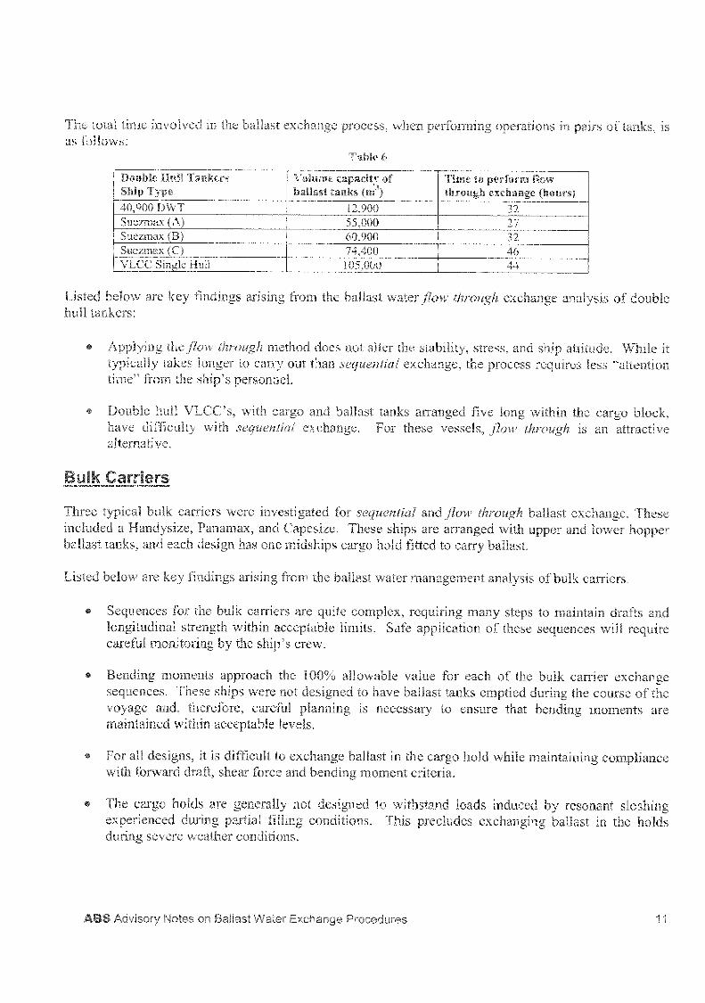
Time to pt:Tforrn flow through, u.sch:lulle (hours
32 27
1'2 ,9 55,000 60,900 74,400 105,000
The , 01 ' VE he ball s c ange process performing operations in of tanks, is as-
sted below are key findings arising ro the ballast water flow through exchange analysis of double hull tankers:
flow through re;`io: docs r the stability, typically takes longer to carry Out Itt,2i1 I exchange, • time" from the ship's personnel.
, and ship attitude° process requires less
• Double hull VLEC's„ with cargo and ballast tanks arranged five long within the cargo block, have :I-lenity with sequential exchange. For these vessels, flow ullrough is an :.i;:tractive atern:-
Bulk Carriers
Three typical bulk carriers were investigated for sequential and flow through ballast exchange. These included a Handysize, Panamax, and Capesize. These ships are arranged with upper and lower hopper ballast tanks, and each design has one midships cargo hold fitted to carry ballast.
Listed below are key findings arising from the ballast water ynailaleITICIlt analysis of hulk carriers.
• Sequences for the bulk carriers are quite complex, requiring many steps to main] a., 1. drafts and longitudinal strength within acceptable limits, Safe application of these sequences will require carefu monitoring by the ship's crew.
▪ Bending moments approach the 100% allowable value for each of the bulk carrier exchange sequences. These ships were not designed to have ballast tanks emptied during the course of the voyage and, therefore, careful planning is necessary to ensure that bending moments are maintained within acceptable levels.
▪ For all designs, it is difficult to exchange ballast in the cargo hold while trraintaining compliance with forward draft, shear force and bending moment criteria.
• The cargo holds are generally not designed to withstand loads induced by resonant sloshing experienced during partial filling conditions. This precludes exchanging ballast in the holds during severe weather conditions.
- , 'visory Notes on Ballast Water Exchange Procedures

Bulk Carriers Ship Type — Ballast condition
Handysize • wfrif Batlast Ballast
Nonr.al Ballast .11eavyBallast
.NormaIlast
• Panamax
Capesize
:Jar to tankers in that they are se>f,i.uencey. .ere evaluated for each bulk carrier. Part
The total time involved in the ballast exchange process is as follows:
1 and
Table 7
Time to perform exchange sequence (hours)
Additional time to ballast to original drafts (hours)
27 40 9 17 6 11
36 4 44 8
Observations related to th.: development of exchange sequences for the bulk carriers are as follows:
• Sequences are relL,. •ely compL..c. as draft forward. draft aft, and ben.dimi -”nents: r tenth approach the limit:hg values. We vessels investigated the sequences rei., - between 12 and 19 independent steps, and up to 65 ballast movements.
• it is difficult in concurrently maintain adeqt propeller immersion and forward draft.
Capesize vessels generally have large double bottom ballast tanks extending two holds in length. It may not be possible to exchange some ballast tanks when th.e cargo hold is filled wig ballast water, as excessive shear forces are encountered. In situations where the hold is emr:,ied, the drafts are greatly reduced to near those in the light ballast condition.
Shear force values for all of the Heavy ballast condition sequences that were studied are close to allowables.
• The Panamax vessel is fitted with overboard valves in the upper hopper ballast tanks, This allows quick gravity discharge of the ballast, significantly reducing the sequence time and providing more flexibility in how the pumps are used.
Flow through exchange
The flow through method eliminates concerns of exceeding shear force and bending moment limits. Flow through exchange is an attractive alternative to the sequential exchange for the Capesize heavy ballast condition; it eliminates the light draft problem associated with sequential exchange.
12 ABS Advisory Notes on Ballast Water Exchange Procedures

Bulk Carriers Ship Type
Volume capacity of ballast tanks (ma)
Time to perform flaw through exchange (hours)
Handysize 1 17,200 Panamax 32,300
Capesize 69,700
46 50 45
me involved in the ballast ex chatwo process, oaerations 3 paiis oi Lat:=.s, is
Table 8
Example of a sequential exchange procedure for a Handymax bulk carrier
To illustrate the complexity of a sequential procedure the following is presented as an illustration of a procedure that was developed for a Handymax bulk carrier. This is a 28,000 DWT bulk carrier with 5 caw, Bolds and 5 P&S sets (a set consists of upper and lower tanks) of hopper ballast tanks. Ballast is
oeasted to the Forepeak, Hold No.3, and Aftpeak as shown below. Two ballast exchange sequenceE, Normal and Heavy, have been reviewed for this vessel. The vessel has two ballast pumps (each rated for 500 m3/hr).
Figure 3
General arrftn...,:nlient / tank la:/
Two initial ballast conditions were investigated for this bulk carrier. Further details on the Normal sequence are included here for illustration of a typical bulk carrier example. For the Normal sequence, there are 19 steps and 28 ballast movements and it takes 27,1 hours to complete. The initial condition for the Normal ballast condition has all ballast tanks full and the Hold No.3 (Ballast Hold) empty, The sequence starts and ends with the same tank levels, which is all ballast tanks at 100% capacity. This exchange sequence is quite complex. For instance, during the sequence the Forepeak Tank is emptied (step 1), filled to 10% capacity (step 2), filled to 30% capacity (step 6), filled to 35% capacity (step 14), and then filled to 100% capacity (step 18). This approach is necessary in order to satisfy the bending moment and propeller immersion requirements while maximizing forward draft.
ABS Advisory Notes on :Neter Exchange Procedures 13

T12le
Peak Value. Limiting "Valz.ie
100% propellei. itEnt,2rsion
Assumed 2.th
I Assumed 0.0
values are Inc: divfs for forward
AP
11 I FP tr
ftj TV Deadzone (m)
Siiç ife:1
5.92
3.02
3.30
6.2
1.4
341
Vu ii.
5.92
4.00
2,39
0.15
1.0
IMO A167
Assumed
IMO NISC/C.i,-,-
Ailo7cah1e) [max]
97%
A' --vv.; Hi
67%
Details of the step-by-step ballast exchange sequence are presented on pages 15 to 17.
14 ABS Advisory Notes on Ballast Water Exchange :"rocaiiires
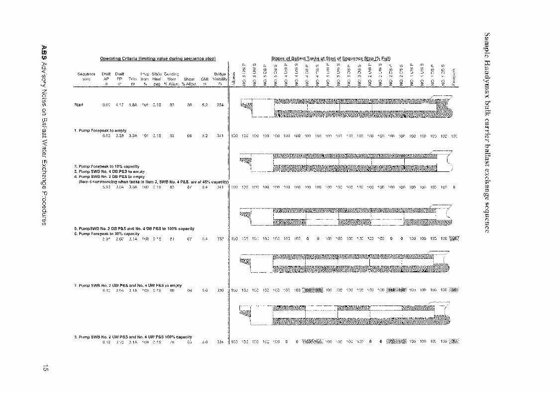
Start 6,00 4.17 1.8A 101 0.15 83 66 6.2 264
1. Pump Forepeak to empty 6.00 3.28 3.3A 101 0.1S 113 66 6.2 341
2. Pump Forepeak to 10% capacity 3. Pump SWB No. 4 DB P5S to empty 4. Pump SWB No. 2 DB P5S to empty
(Item 4 commencing when tanks in item 3, SWB No. 4 P5S, are at 48% capacity) 5.93 3.04 3.3A 100 0.15 33 67 6.4 341
5. PumpSWB No. 2 DB P55 and No. 4 DB P&S to 100% capacity 6. Pump Forepeak to 30% capacity
5.94 3.06 3.1A 100 0.15 81 67 6.4 332
7. Pump SWB No, 2 UW P56 and No. 4 UW P&S to empty 6.10 3_04 3.1A 103 0.13 80 66 6.6 336
8 Pump SWB No. 2 UW P&S and No. 4 UW P55 100% capacity 6.16 3.10 3.1A 104 0.18 78 65 6-G 334 100 100 100 100 100 0
;se/
leg
uo s
emi
A.os
i sa
mpe
owci
a5u
e.q3
x
07
NO
.S
UW
S
NO
. 5 L
AN
P
NO
. 5 05 P
C] cJ W7 CO N IN
z 0 0 z z
Status of Ballast Tanks at Start of Sequence Step 1% Full) .01
z NO
. 2 0
8 P
1:* S a S
NO
. 4 U
VV P
NO
. 4 U
V,/ S
NO
. 3 L
ON
P
NO
. 4 D
B S
NO
. 3 D
B P
NO
. 4 0
E3 P
NO
. 3
UW
S
NO
. 2 0
8 S
0. in
o
b
NO
. 1 L
AN
S
0 z
Operating Criteria (limiting value during sequence step)
Sequence Draft Draft Prop Static Bending Bridge step AP PP Trim Imm. Heel Mom Shear GMI Visibility
% deg % MOW. % Allow. rn En
100 100 100 100 140
100 100 100 100 100
100 100 100 100 100
100 100 MO 100 100
100 100 100 100 100
if 100 a 0 100
100 100 100 'en
100 100 100 100 100 100 100 100 100
100 100 100 100 100 100 100 100 100
100 100 100 100 100 0 0 100 1 I
100 100 100 100 100 100 100
100
100 100 100
100 100 0
100
100 1011
1Ctt3 100 140 100 100
Operating Criteria (limiting value d ng_sequence step)
NO
. 1 O
W S
try
0
to
0 15
oc
0 z
Sequence Draft Draft Prop Static Bending Bridge step AP FP Trim Imm, Heel Mom Shear Gtiiit Visibility .
deg % Altow. % Allow.
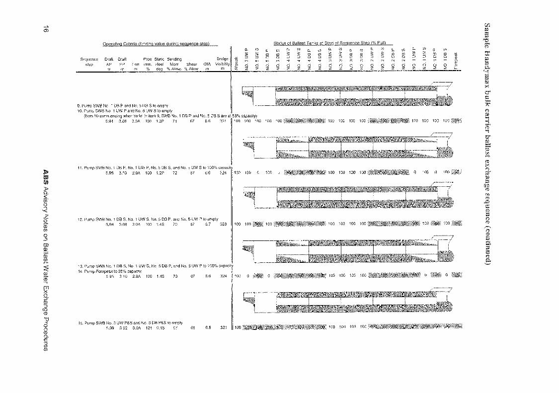
9. Pump SWB No. 1 DB P and No. 5 BB S to empty 10. Pump SVVB No. I 1.1W P and No. 5 OW S to empty
(Item 10 commencing when tanks in item 9, SWB No. 1 DB P and No. 5 DB S are 3 5.94 3.08 3.0A 100 1.2P 71 67 6.6 331
11. Pump SWB No. 1 DB P, No. 1 UW P, No. 5 DB S, and No. 5 UW S to 100% capacity 5.95 3.10 2.9A 100 1.2P 72 67 6,6 324 100 100 0 100 0
12. Pump SWB No. 1 DB 5, No. 1 OW 5, No. 5 DB P, and No. 5 UW P to empty 5.94 3_08 3.0A 100 1.45 70 67 6.7 328
13. Pomp SWB No. 1 DB 5, No. 1 OW S, No. 5 DB P, and No. 5 UW P to 100% capacity 14. Pomp Forepeak to 35% capacity
5.95 3.10 2.9A 100 1.45 73 67 6.6 324 100 0
15. Pump SWB No. 3 UW PaS and No. 3 013 P&S to empty 5.99 3.02 3.0A 101 0.15 97 66 6.6 331
100 100 100 100
100 100 100 100 •
100 100 100 'IO0
100 100 100 100
100 100 100 100 1..1CI
AB
S A
dviso
ry No
tes on
Ba
llast W
ate
r Exch
ang
e P
roce
dure
s
(5- )
Status of Ballast Tanks at Start of Sequence Step (% RIR) cu to
O 0 • 0 in -a- ita O z o
1
N
N
N
100
NO
. 2 O
W P
NO
.2U
WS
NO
. 2 D
B P
NO
. 3 D
S S
NO
. 3 D
B P
NO
. 3 CM
P
NO
. 3 U
W S
NO
. 4 D
B S
NO
. 4 D
B P
1Iv1
is
!-:73
to 02
foa 5
to
02
to
-4-
C.F0
co)
to
100 10 100
55% capacity) 100 100 100 100 100 1 t/..! 1 1 100 100 10C '

sequence stet: Operating Criteria (limiting value durin
0 ca
cu
Or
ru
rV
O O
Cn CC
II T.)
z
16. Pump SWB No. 3 UW P&S and No. 3 DB P&S to 100% capacity 6.07 3.10 3.0A 102 0.1S 93 66 6 5 320
17. Pump Aftpdak to empty 6.20 3_66 2_6A 106 0.1S 70 60 8.9 300
18. Pump Forepeak to 100% capacity
19. Pump Attpeak to 100% capacity 5.92 3.83 2.2A 100 0.1S 83 66 6.2 284
Finished 6,00 4.17 1.8A 101 0 IS 93 66 6.2 264
AB
S A
dviso
ry Note
s on
Ballast W
ater Ex
chan
ge P
roced
ures
cr.) 00
a FU
00
00
00
et)
Status of Ballast Tanks at Start of Sequence Step (% Fultf
0 0
(pan
tmuoa)
33uanbas a
Sequence Draft Draft Prop Static Bending Bridge step AP FP Trim Imm, Heel Mom Shear GM Visibility
m m % deg % Allow, % Mow_
100 '0.,
tt 1 0 10.
r
rely operate "ballast nelitier :en or containers gen,.,, aded an, off-loaded at ce:: . 3a1 ry
/oyage to accomrnodate e d;stribudon of ca7.-gu are, consemab' ,onse o cperational requirements such traft iitations. For containers. liris the procedure more
o "management plan" than a ballast exchange process.
There are a number of sometimes-conflicting objectives facing the containership planner as containers are assigned to specific slots on the vessel. There is strong economic incentive to avoid re-handling of containers (i.e. moviftc- containers to allow the cargo below to be off-loaded or shifting containers to adjust for trim or strengthlimitations). Stowage preferences limit the planner's ability to optimize with regard to trim, bending moments, and stability, and it is unlikely that container stowage could be significantly modified to facilitate ballast exchange.
However, the fact that containerships retain cargo onboard dirougout the vcr,ag presents some benefits with regard to ballast .management. Some tanks may remain permanen tanks can be maimained permanently full with locked in ballast: and it may be possible to discharge other tanks at sea rather than in port. For a given trade, the quantities and weights of containers loaded anc-.-;Ja.d,-,,d
each port generally follow repetitive and/ or o'ends. These historical data are used by planners to pre-plan stowage, and by ship Masters to aid in their decisions regarding allocation of ba•last and consumables. By pre-planning an entire voyage cycle, it is expected inat the amount of ballast moved and particularly the need19 discharge ballast in port can be minimized.
This study investigated the practicality of a ballast management approach that considers entire voyages for three containerships. The ships selected for this analysis include a 1200 TEL]. feedership operating between Northern Europe and the Mediterranean Sea; a 2500 ILL Panamax containership operating between the U.S. West Coast, Hawaii, end 'Japan; and a 4800 Post-.Panamax coiltainers operating, in the U.S.-Far East trade. For each ship, the following investigations were carried out.
Development of voyage specific ballast water management approaches: A complete voyage cycle was developed using historical data from actual voyages for container weights and distributions, and other consumables. As far as practical, the actual ballast allocation scheme was also retained, although adjustments were made to eliminate the discharge of contaminated ballast in port or during inter-port legs through shallow waters. When allocating ballast, priority was given to maintaining compliance with the stability and strength regulations. An effort was also made to maintain the draft, trim., list, propeller immersion, and visibility within the acceptable limits. Within these constraints, ballast was allocated in order to minimize the amount of ballast to be discharged in port or coastal waters. When deballasting in port was unavoidable, the ballast was either originally loaded in deep ocean waters or an exchange was carried out in deep water.
18 ABS Advisory Notes on Ballast Water Exchange Procedures

1200 TEU Feeder 440 (Coastal orate
4800 TEU Post-Panamax 500 TEL Panarnax
930 I 0,600 11,100
3,700 (Dee Ocean
st no.ve, nts for each vessel (voyage) are summarized in table 10.
Table 10
Total ballast movement Ballast discharged in e in during voyage (MT)
Containerships Ship Type port (MT)
The 1200 TEU Feedership was the only vessel where required in-port discharge of coastal ballast water. For this Feedership, tanks are maintained empty or pressed up throughout the voyage with the exception of the No. 2 Wing Tanks PIS, which are used to control heel during cargo operations. As the ballast system does not allow for internal transfers, it is necessary to discharge a total of 440 MT of coastal ballast water while in port. if it were possible to transfer ballast between this pair of wing tanks, zero discharge of ballast could be achieved for the voyage.
For the three voyages that were evaluated, effective ballast water management procedures can be implemented with little impact on vessel operations. Nevertheless, it should be recognized that a containership loaded to its marks and approaching GM or bending moment limits will be unable to exchange ballast without exceeding allowables. Generally this will only impact Panamax and smaller vessels. The post-Panamax containerships have ample excess ballast, deadweight capacity, and stability margin to bring additional ballast onboard before initiating the exchange process.
Impact of ballast water exchange on ship properties: To assess the "worst case" scenario, each vessel was fully loaded to her summer loadline draft in such a way that both the GMt (actual GM equal to the required GM) and still-water bending moment (actual still-water bending moment equal to the permissible still-water bending moment) were at their limiting values. Each tank was run through an exchange sequence to determine the effect of the exchange on the drafts, trim, propeller immersion, static heel, still-water bending moments and shear forces, GM, and bridge visibility. Containers were then removed from the upper-most tiers on deck until compliance with the stability and strength criteria could be maintained throughout the exchange process.
To assess the impact of emptying and re-filling tanks, each ship was loaded to its loadline such that the GM equals the minimum permissible, and the still-water hogging moment is at maximum permissible value. Then each tank or pair of tanks was run through an exchange cycle. The maximum changes to the stability and bending strength characteristics encountered during the exchange of any one tank or pair of tanks is displayed in table I I:
Table 11
Containerships Ship Type
Maximum change to hogging bending moment
Maximum change to GMt (m)
1200 TEU -- Feeder 17% 0.52 2500 TEU -- Panamax 10% 0.36 4800 TEU --- Post-Panamax 8% 0.54
Containerships are frequently stability and strength limited. Ballast exchange has a detrimental effect on stability due to the introduction of free surface effects as the tanks are made slack, as well as the rise in the ship's center of gravity as double bottom tanks are emptied. As shown above, the maximum
ABS Advisory Notes on Ballast Water Exchange Procedures 19

Reduced payload to account Reduced payload to for change in bending account for change in GN11 moment
Containers hips Ship Type
1200 TE 1474 MT 17% B.M.hange 759 MT / 0.52rn GM, chan cec e 2500 TEU — Panamax 4800 TEU Post-Panamax
345 MT / 10% B.M. change 950 MT / 0.36m GM, change 1965 MT / 8% B.M. change 1930 MT 10.54m GM, change
reduction in GM, during the exchange of a tank or pair of tanks on the three vessels range. from 036 to 0.54 meters, and the increase in hogging moment ranged from 8% to 17% of the alovi:r...1:1e. The table below provides values for the reductions in payload required to allow exchange of those tanks; if the initial load condition has the vessel fully loaded to her marks with stability and bending moments at their limiting values. As illustrated in the analysis of the three containerships, such payload losses can generally be avoided as ballast can be "locked in" when a vessel is heavily loaded.
Table 12
Listed below are key findings arising from the ballast water management analysis of containerships:
• The 1200 TEU feedership does not have heeling tanks or other means for internally transferring ballast from side to side. Since ballast adjustments are required to control list during cargo operations, there is no alternative but to discharge ballast in port. A substantial portion of the voyage for the 1200 TEU vessel studied involved inter-port transits through shallow waters.lt was not possible to exchange ballast water in the deep ocean, resulting in unavoidable in-port discharge of coastal waters.
• With the exception of the above mentioned problem of controlling heel on the feedership, it was found that for the three voyages and ships analyzed, effective ballast water management procedures can be implemented with little impact on vessel operations and with no loss of container payload.
• Through planning, the amount of ballast exchange can be minimized, as many tanks can be maintained either full or empty during the course of the voyage. in preparation of a port call, tanks can often be initially ballasted in the deep ocean, which further reduces the need for exchange.
Slamming
For the ballast exchange operations studied, it was common to have a decrease in forward draft during ballast exchange sequence operations. This was particularly evident in the case of tankers and bulk carriers. In order to consider the implications of the reductions in forward draft, a seakeeping analysis was performed. The goal of this analysis was to determine limits on sea conditions to reduce the incidence of slamming to an acceptable value. The acceptance criteria for slamming used in the study was a 3% (3 slams in 100 pitch oscillations) slam probability for tankers and bulk carriers, and a 5% slam probability for containerships. Each vessel was investigated using, actual ballast conditions as presented in its loading manual. In addition, each tanker was investigated using the minimum forward draft peiinitted by MARPOL 78. (Load cases identified in table 13 by the notation "IMO" are load cases that considered the minimum MARPOL 78 forward draft). To briefly summarize the analysis: Acceptable slam probabilities are achieved for all vessels at significant wave heights below 8 meters (approximately Beaufort Force 7, Moderate Gale).
20 ABS Advisory Notes on Ballast Water Exchange Procedures

The resulting limits of significant wave heights, where slamming acceptance criteria are not satisfied, are as follows:
Table 13
Vessel type Ceneral description I Load case Maximum Hi/3 1 wave height (m)
Single hull tanker 35,000 .DWT
Suezmax
Normal IMO Normal
8 8 12
IMO 12 VLCC Normal 12
FMO j 12 Double hull tanker 40,900 :DWT Normal I 9
IMO 8 Suezmax (A) Normal 12
IMO 12 Suezmax (B) Normal 12
IMO 12 Suezmax (C) Normal 12
IMO 12 VLCC Normal 12
IMO 12 Bulk carrier Handy-size Normal L 9
Panamax ' Normal 12 Capesize Normal 12
Containership Feeder (1200 TEU) Full 12 Full* 10
Panamax (2500 TEU) I Full 12 Full* 10
Post-Panamax (4800 TEU) 1 Full 12 Full* 1.1
* Limiting modified full load "actual voyage condition"
Sloshing
Despite the violent nature of the sloshing phenomenon, little damage has been seen to date, in the three types of vessels considered in this document. The damage that has been reported has mainly been limited to long cargo tanks in large tankers, and to cargo holds in dry cargo ships that have been partially filled for ballasting purposes, especially in bulk carriers. Sloshing loads are not much of a concern in double-bottom or double-hull tanks, as the dense internal structure of these tanks usually restricts the fluid motion to such a large extent that resonant sloshing can not occur. Therefore, sloshing analysis is confined to large tanks on tankers and cargo holds on the bulk carriers.
Sloshing analysis was performed on the three single hull tankers (35,000 DWT, Suezmax and VLCC) and on the Panamax and Capesize bulk carriers. Sloshing resonance was a problem in the single hull Suezmax tanker and in both of the bulk carriers. However, one should not draw any conclusions regarding the acceptability of the smaller tankers and VLCC's. Sloshing is highly dependent on tank geometry and structure, which can vary greatly from one vessel to another. Sloshing in tankers is generally limited to pitch resonance, and can usually be rectified with only modest mitigation design measures. such as changes to tank geometry, or the addition of swash bulkheads. Sloshing in partially
ABS Advisory Notes on Ballast Water Exchange Procedures 21
filled holds on bulk carriers may be due to pitch and/or roll motion resonzlnce. and is a major concern that is not easy dealt with.
In the case of single hull tankers it is possible to reduce sloshing motion amplitudes and to bring the loads on the structure within acceptable limits. For the Suezrnax tanker considered in T.Y.S study, by limiting the vessel's pitch amplitude to that encountered in seastates of Beaufort Force 7 or less, sloshing loads would be brought down to acceptable limits, making the study vessel satisfactory with respect to sloshing in a majority of sea conditions. Similar operational limits would not be practical for ballasting of bulk carrier cargo holds.
Listed below are key findings arising from sloshing analysis:
• Single hull tankers and bulk carriers typically have tanks of sufficient size and proportions to pose sloshing concerns.
• Sloshing loads in single hull tankers need to be carefully considered in the development of ballast exchange sequence scenarios.
• At sea ballasting of bulk carriers cargo holds using procedures that involve partially filled hold spaces is considered impractical for most conventional bulk carrier designs.
Comments on Damage Stability and Survivability
Survivability was assessed based on a probabilistic damage stability analysis for a limited number of vessels. The conclusion of our assessment was that because the conditions involved were ballast conditions, the survivability was quite high, both for the normal ballast condition and for the "worst case" Ballast Water Exchange condition.
Comments on the Probability of Completion of Ballast Water Exchange
Assuming no interruptions, the duration of exchange sequences evaluated in this study ranged from 1/4 day to 2 days. In general, a ballast sequence can be interrupted and continued with some additional time requirements to return from the ballast condition required to operate in the higher sea conditions. However, this is not the desired behavior. Ideally, once the ballast exchange sequence has begun it should proceed until completion. From published data it is concluded that even with a series of conservative assumptions, the probability of completing a 44 hour exchange sequence in any given 44 hour period is over 95%.
For some relatively short routes, e.g. the TAPS trade on the U.S. West Coast, there may be concerns over completion of the sequence once interrupted. Fortunately, the duration of sea states above 7.5 m significant wave height are relatively short. Published data indicates that storms with significant wave heights over 7.5 m (i.e. Beaufort 7 and above) have an expected duration of 7 hours. Thus interruptions to ballast exchange should be short and only exceptionally short voyages with long sequences should be compromised.
22 ABS Advisory Notes on Ballast Water Exchange Procedures

:ftfrimariz the finigs of a study that focuses on the use of ballast management pract;e.,,ts. T..he rt ci' ballasC 1,anagemcnt is to minimize the discharge of ballast in port and coastal .0,..aters, and wile:: st.:ell discharzes cannot be avoided, restrict them to ballast that has been loaded or exchanged in the open-ocean. This is done in order to limit the discharge of ballast water that may contain unwanted aquatic organisms. Shipowners and designers have only recently become aware of the importance of ballast management—therefore, when the existing fleet of cargo vessels was designed, little or no consideration was given to the ability to exchange ballast As a consequence, exchange sequences can be quite complex, and a wide range of issues including stability, hull girder strength, resonant sloshing, slamming, and propeller immersion must be considered.
Two general conclusions emanating from this study are:
The complexity of exchange sequences on certain vessels present safety concerns, as human error and equipment failures could potentially endanger the vessel. Personnel training will be an essential part of a ballast water management program. System reliability may also be a concern, particularly on older ships.
2. Ballast exchange should be given due consideration during the design process. The ballast system layout, ballast capacity, tankage configuration, and hull girder strength are a few of the design decisions which influence the ability to sequentially exchange ballast. When sequential exchange is impractical, the overflow system should be arranged so that flow through can be carried out without risk of over-pressurizing tanks.
ABS Advisory Notes on Ballast Water Exchange Procedures 23