Advantages of special lenses for top and side inspection ...
12
This document is dedicated to machine vision engineers and automation experts who might profit from smart optical approaches to their vision applications. This is a very interesting and wide topic that would require a much longer discussion… that’s why we can’t wait for you to contact us to find out more! Advantages of special lenses for top and side inspection vs multi-camera systems White Paper Many machine vision applications such as OCR/barcode reading on bottles and containers or defect detection inside threaded bores, require to inspect features randomly located both on the part outer or inner sides and on the top and bottom surfaces. In these cases, the most common approach is to use multiple cameras in order to achieve several side views of the part, in addition to the top/bottom view. However, a setup consisting of multiple cameras and lenses is sometimes too bulky to fit demanding space constraints on the line, and depth of field issues arise when imaging at high magnification. Also, in multi-camera systems many images need to be processed, which might take long elaboration times when dealing with high-end applications, thus limiting the system speed/through-put or requiring expensive high performance PCs. In fact, in these cases additional hardware is needed: multiple acquisition cards, a GPU card for parallelization, together with multiple power supplies and cables. In other cases, vision engineers prefer to scan the outer surface with line scan camera systems. This approach also shows many technical and cost disadvantages: the object must be mechanically rotated in the FOV which also lowers the inspection speed; moreover, line-scan cameras require very powerful illumination. Also, the large size of linear detectors increases the optical magnification of the system, thus reducing field depth. For these reasons, Opto Engineering® developed special optics designed to inspect top and sides with one single camera and without any need for part rotation.
Transcript of Advantages of special lenses for top and side inspection ...

This document is dedicated to machine vision engineers and automation experts who might profit from smart optical approaches to their vision applications. This is a very interesting and wide topic that would require a much longer discussion… that’s why we can’t wait for you to contact us to find out more!
Advantages of special lenses for top and side inspection
vs multi-camera systemsWhite Paper
Many machine vision applications such as OCR/barcode reading on bottles and containers or defect detection inside threaded bores, require to inspect features randomly located both on the part outer or inner sides and on the top and bottom surfaces. In these cases, the most common approach is to use multiple cameras in order to achieve several side views of the part, in addition to the top/bottom view. However, a setup consisting of multiple cameras and lenses is sometimes too bulky to fit demanding space constraints on the line, and depth of field issues arise when imaging at high magnification. Also, in multi-camera systems many images need to be processed, which might take long elaboration times when dealing with high-end applications, thus limiting the system speed/through-put or requiring expensive high performance PCs. In fact, in these cases additional hardware is needed: multiple acquisition cards, a GPU card for parallelization, together with multiple power supplies and cables.In other cases, vision engineers prefer to scan the outer surface with line scan camera systems. This approach also shows many technical and cost disadvantages: the object must be mechanically rotated in the FOV which also lowers the inspection speed; moreover, line-scan cameras require very powerful illumination. Also, the large size of linear detectors increases the optical magnification of the system, thus reducing field depth.For these reasons, Opto Engineering® developed special optics designed to inspect top and sides with one single camera and without any need for part rotation.

Special lenses White Paper
2
Machine vision lens typesConventional machine vision lenses, smartphone lenses, video surveillance lenses, and our eyes are called entocentric lenses. This term means that they have the entrance pupil placed inside the lens: basically, they can frame diverging light rays. Imaging with diverging rays also means that two objects of the same size, when placed at different distances from the lens, will appear to have different dimensions – the one closer to the lens appear larger than the one located farther. This is the well-known “perspective effect”.
There are also telecentric lenses, with the entrance pupil “at infinity”. They frame light rays parallel to the optical axis of the lens. Imaging with parallel rays means that two objects of the same size, when placed at different distances from the lens, will actually look the same (lack of perspective).
There is also a typology of lens called pericentric lenses with the entrance pupil outside the lens: basically, they can frame converging light rays. Imaging with converging rays
means that two objects of the same size, when placed at different distances from the lens, will appear to have different dimensions - the one closer to the lens appearing smaller than the one located farther. In practice, this means that the top-down image of a bottle cap will provide not only the top surface, but a “wrapped” view of the sides as well.
Opto Engineering® 360° view lenses have a main and key feature: they produce a 2D image of a 3D object. In other words, they can frame curved three-dimensional surfaces into a focused image on the camera sensor, that is a two-dimensional plane surface. They are named after this feature: only one camera to obtain a 360-degree inspection.
This special feature can be obtained in two ways, either by optical design (pericentric lenses) or by a combination of optics and mirrors. Multi-mirror lenses offer the advantages of combining the special quality of the optics (e.g. telecentricity on TCCAGE SERIES lenses) with the 360° view on multiple mirrors.
Entrance pupil
Convergent rays
A telecentric lens by Opto Engineering® with its light path and entrance pupil position.
An entocentric lens by Opto Engineering® with its light pathand entrance pupil position.
A pericentric lens by Opto Engineering® with its light path and entrance pupil position (top) and an example of “wrapped” view of a cylindrical container.
A multi-mirror lens by Opto Engineering® from the TCCAGE SERIES, combining a telecentric lens with a system of prisms and mirrors.
Hei
ghtMax 24°
WD
diameterØ
Det
ecto
r sh
ort s
ide
Hei
ght
Diameter
Entrance pupil
Diverging rays
infinity
infinity
Entrance pupil
Parallel rays

3
Opto Engineering 360° optics are a compact solution which requires one single camera and is easily set up on the line. The compactness of the solution is especially important in many situations where space constraints force the vision system to acquire a top-down image of the object.
With their various combination of optical designs, these lenses are perfect for the inspection of medium-small samples (<100 mm, down to 5 mm) in online applications. Working with a single camera means short setup times (no complicated calibrations and mechanical adjustments) fewer hardware components (cables, acquisition cards, power supplies…) and/or less expensive hardware (no need for multiple acquisition cards, GPU cards or frame grabbers).
Dedicated illumination is available (e.g. LTRNOB SERIES of ring lights for PC, PCCD and PCHI SERIES) or directly integrated with the optics (e.g. TCCAGE, PCMP, PCBPN).
These lenses are all by design customizable, in terms of resolution (e.g. 1” versions), dimensions (larger/smaller samples), angle of view, illumination.
Centering of the object is important: when using 360° OPTICS, a special software tool included in Opto Engineering 360LIB SUITE facilitates this operation.
360LIB Suite is a C++ based computer vision software designed to optimize the optical performances of 360° optics setups. With the use of both a .dll library and dedicated stand-alone tools, 360LIB makes it easy to take care of the correction of decentering and image unwrapping.
Advantages of Opto Engineering® 360° View lenses
3
Example of a setup using Opto Engineering® PC SERIES lenses. Simple image processing, sample spacing requirements to a minimum and the combination with a dedicated high power illumination ensures the maximum speed.
Special lenses White Paper
In many machine vision applications, samples on the line are oriented at random and their appearance to a front-facing inspection point cannot be predicted. Space constraints might force the inspection to be top-down only, and the throughput requirements can be extremely high.
Let’s now focus on the differences between standard solutions (multicamera systems, line scan approaches) and an equivalent, single-camera, 360° view solution.
OPTO ENGINEERING 360° VIEW LENSES

Special lenses White Paper
4
A setup consisting of multiple cameras and lenses is sometimes too bulky to fit demanding space constraints on the line. In fact, the presence of multiple cameras positioned all around the object might not be possible.
Also, imaging of small FoVs (<100 mm) with fixed focal length lenses requires the use of extension tubes which worsen the image quality. In fact, when dimensions become small, FFL lenses are not the best optical choice anymore, and integrating higher magnification lenses in a multi-view setup is extremely challenging due to a shallow depth of field, especially when imaging at an angle or inspecting curved surfaces (e.g. bottles). A possible solution for an increased depth of field is to increase the lens f/#, which on the other hand requires more powerful and expensive illuminators.
In multi-camera systems many images need to be processed, which might require long elaboration times when dealing with high-end applications (image stitching, 3D reconstruction), thus limiting the system speed/throughput or requiring expensive high performance PCs. In fact, in these cases additional hardware is needed: multiple acquisition cards, GPU for parallelization, together with multiple power supplies and cables.
Linescan imaging is usually the best approach to obtain high resolution pictures of elongated objects, but it also has many drawbacks. During the image acquisition phase, the object must stay still while the camera rotates around it or vice versa, which makes this approach not compatible with inline applications.
Linescan too has some issues with small, non-flat objects due to limited depth of field provided by the high magnification of the lenses. Also, an additional area scan camera is required for top/bottom inspection.
Linescan imaging requires additional hardware (frame grabbers) and special care in handling the software part of the inspection.
MULTICAMERA SYSTEMS
LINE SCAN IMAGING
Finally, the setup phase of a multicamera system can be very time consuming and the increased amount of hardware present means and increased failure risk.
Example of a multicamera setup. The high number of images to be inspected and the necessary distance between objects can limit the overall throughput of the system
Example of a line scan setup. The requirement of the object to rotate on a fixed axis makes this approach not compatible with in-line applications.

5
Let’s recap!
Special lenses White Paper
DIFFERENCES BETWEEN STANDARD SOLUTIONS AND OPTO ENGINEERING 360° VIEW LENSES
MULTICAMERA LINE SCAN 360° OPTICS
Single camera
Inspection of top and sides
Inline inspection
Compact
Samll FoV
Easy setup
Easy software analysis
General purpose hardware
High throughput
360° View lensesPRODUCT FAMILY OVERVIEW
Metrology White Paper
6
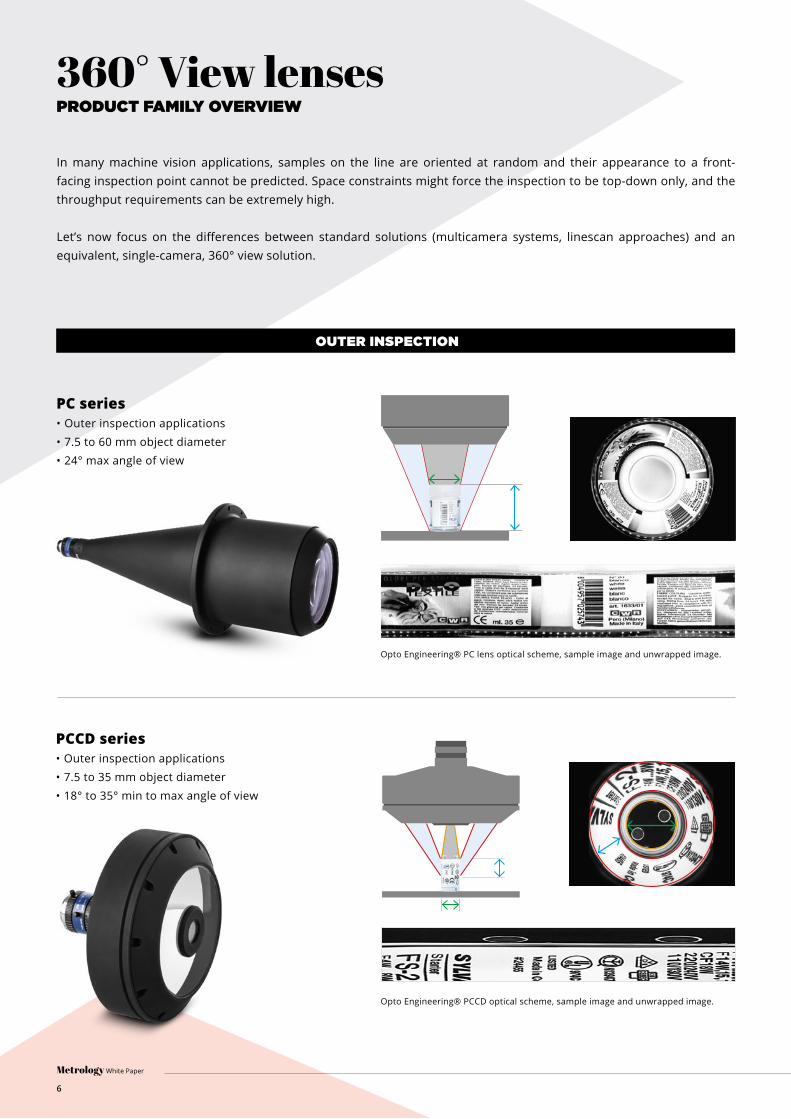
In many machine vision applications, samples on the line are oriented at random and their appearance to a front-facing inspection point cannot be predicted. Space constraints might force the inspection to be top-down only, and the throughput requirements can be extremely high.
Let’s now focus on the differences between standard solutions (multicamera systems, linescan approaches) and an equivalent, single-camera, 360° view solution.
PC series• Outer inspection applications• 7.5 to 60 mm object diameter• 24° max angle of view
PCCD series• Outer inspection applications• 7.5 to 35 mm object diameter• 18° to 35° min to max angle of view
diameter
OUTER INSPECTION
Opto Engineering® PC lens optical scheme, sample image and unwrapped image.
Opto Engineering® PCCD optical scheme, sample image and unwrapped image.

PCHI series• Inner inspection applications• 10 to 120 mm object diameter• 82° angle of view• Available with liquid lens integration
PCBP series• Inner inspection applications• 5.5 to 100 mm object diameter• 60° angle of view• Integrated illumination available
INNER INSPECTION
Opto Engineering® PCHI optical scheme, sample image and unwrapped image.
Opto Engineering® PCPB optical scheme, sample image and unwrapped image.
7
Special lenses White Paper

Special lenses White Paper
8
MULTI-VIEW
TCCAGE series• Outer inspection applications• 8x32 to 16x68 mm object diameter x height range• 90° angle of view• Telecentric view• Integrated top and back illumination
PCPW series• Outer/Inner inspection applications• 30 to 50 mm object diameter• 45° angle of view
PCMP series• Outer/Inner inspection applications• 2.5 to 10 mm object diameter• 37° angle of view• Telecentric view• Integrated illumination
Opto Engineering® TCCAGE optical scheme and sample image.
Opto Engineering® PCPW: optical scheme and sample image.
Opto Engineering® PCMP: optical scheme and sample image.
9
Special lenses White Paper
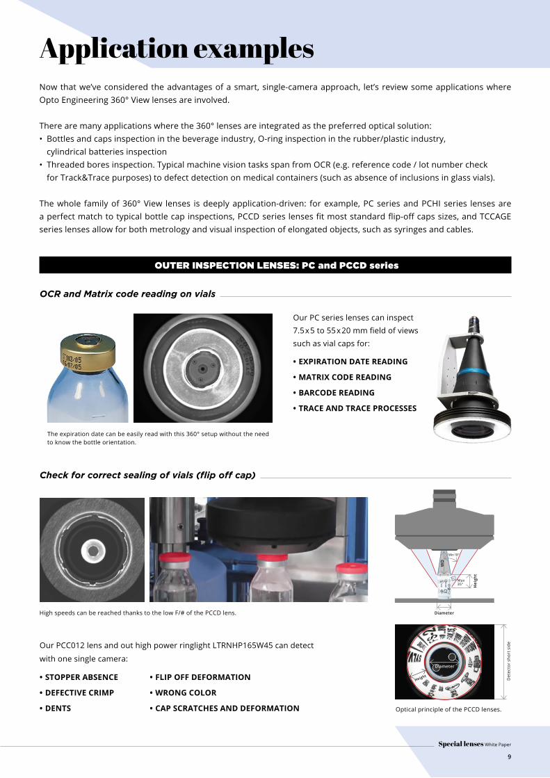
Application examplesNow that we’ve considered the advantages of a smart, single-camera approach, let’s review some applications where Opto Engineering 360° View lenses are involved.
There are many applications where the 360° lenses are integrated as the preferred optical solution: • Bottles and caps inspection in the beverage industry, O-ring inspection in the rubber/plastic industry, cylindrical batteries inspection • Threaded bores inspection. Typical machine vision tasks span from OCR (e.g. reference code / lot number check for Track&Trace purposes) to defect detection on medical containers (such as absence of inclusions in glass vials).
The whole family of 360° View lenses is deeply application-driven: for example, PC series and PCHI series lenses are a perfect match to typical bottle cap inspections, PCCD series lenses fit most standard flip-off caps sizes, and TCCAGE series lenses allow for both metrology and visual inspection of elongated objects, such as syringes and cables.
OUTER INSPECTION LENSES: PC and PCCD series
OCR and Matrix code reading on vials
Check for correct sealing of vials (flip off cap)
The expiration date can be easily read with this 360° setup without the need to know the bottle orientation.
Our PC series lenses can inspect 7.5x5 to 55x20 mm field of views such as vial caps for:
• EXPIRATION DATE READING
• MATRIX CODE READING
• BARCODE READING
• TRACE AND TRACE PROCESSES
High speeds can be reached thanks to the low F/# of the PCCD lens.
Optical principle of the PCCD lenses.
Our PCC012 lens and out high power ringlight LTRNHP165W45 can detect
with one single camera:
• STOPPER ABSENCE
• DEFECTIVE CRIMP
• DENTS
Det
ecto
r sh
ort s
ide
Height
Diameter
Hei
ght
WD
Diameter
Max 35°
Min 18°
• FLIP OFF DEFORMATION
• WRONG COLOR
• CAP SCRATCHES AND DEFORMATION

Special lenses White Paper
10
Glass vials contamination and impurity check
Rotor part inspection
Small mechanical bores inspection
INNER INSPECTION LENSES: PCHI and PCBP series
Backlighting provides a high contrast on the features of interest.
PCHI lenses can be customized changing the angle of view to maximize resolution on specific diameter x height samples.
Our PCHI series and powerful homogeneous LTBP backlights are used for:
Our PCBP series lenses can inspect 25 to 100 mm diameters, such as engine rotors, for:
Our PCBPN013-WG lens can inspect diameter from 8 mm to 25 mm, looking for:
By focusing the bottom and inner walls with one single camera at high resolution.
• RESIDUALS AND CONTAMINANTS CHECK
• PRESENCE/ABSENCE
• DEFORMATIONS
• INCLUSIONS
• BLEMISHES
• DENTS
• THREADS PRESENCE/ABSENCE
• SCRATCHES
Cavity bottom
Hole inspection optics
Cav
ity
vert
ical
wal
l
Rotor part imaged with PCBP lens. Internal walls can be completely inspected.
Unwrapped image. 360LIB-01 dedicated software library is available to easily and accurately unwrap the images.
PCBN013-WG lens provides enough resolution to precisely inspect very small bores, such as the d = 8 mm bore of this example. PCBPN013 lens can go down to 5.5 mm (separated illumination required).
Camera
PCBPN013-WG
64 mm probe length
7 mm probe diameter
8-25 mm diameter
Integrated illumination
d
d

Cannula dimensional gauging
Cannula dimensional gauging
Check for defects in flip-off caps for vials
MULTI-VIEW LENSES: TCCAGE, PCPW and PCMP series
The combination of prism and beamsplitter provides two telecentric images on the object from a single lens.
TCCAGE can be customized with 0.5 x magnification and two 90° views for needle measurement (e.g. 17 mm needle height on a 60 mm syringe).
The lack of perspective given by the telecentric view of TCCAGE provides a quick alignment check regardless of the part orientation.
Optical principle of the PCMP multiview lenses.
The 45° viewing angle of PCPW provides high resolution on the lateral details of the sample.
Our TCCAGE multiview telecentric lens can be used to measure:
Our PCPW SERIES lenses can inspect 30 to 50 mm diameter objects, such as flip-off caps for vials:
• CANNULA ANGLE
• CANNULA BOW
• DEGREE OF ALIGNMENT
• CUTS
• SCRATCHES
• CONTAMINATIONS
• SPOTS
d
Our PCMP optics is designed for the imaging of small elongated objects from multiple angles with a single camera system, to perform:
• ELABORATE DIMENSIONAL MEASUREMENTS
• BURR DETECTION
• HOOK DETECTION
PCMP can be customized to see smaller fields of view, such as 0.33 mm diam x 3.36 mm height needle tips.
11
Special lenses White Paper
WWW.OPTO-E.COM
Company profileOpto Engineering® was born in September 2002, founded in Mantua by Claudio Sedazzari, Andrea Bnà and Andrea Vismara. The founding
partners have gained a long-standing experience as consultants in the field of machine vision. The newborn company starts to operate in
the field of industrial optics by providing design services to companies in a variety of fields such as machine vision, sensors, lighting, lasers,
safety and electro-medical equipment.
By intercepting a growing demand
for non-contact metrology systems,
Opto Engineering decides to develop
its own range of lenses for metrology
applications with an original and
innovative design. Italian customers
starting to look at this kind of
applications immediately demonstrate
interest and appreciation for the new
product offering by Opto Engineering, THE TELECENTRIC COMPANY®.
Opto Engineering THE TELECENTRIC COMPANY has evolved through the years, releasing hundreds of new, diverse products and developing
multiple areas of expertise. Today we can say that we specialize in OPTICAL IMAGING TECHNOLOGIES.
Our focus is to build and provide every single component needed to solve imaging applications: starting from the optical know-how and
going through competence in lighting we can supply the best combination of tools available on the machine vision market.
For all these reasons Opto Engineering® has become the partner of choice in high-end optical applications for many of the major machine
vision companies worldwide. Opto Engineering, OPTICAL IMAGING TECHNOLOGIES.
EUROPE
ASIA
UNITED STATES
Opto Engineering
Europe Headquarters
Circonvallazione Sud, 15
46100 Mantova, IT
phone: +39 0376 699111
Opto Engineering
China
Room 1903-1904, No.885, Renmin RD
Huangpu District 200010
Shanghai, China
phone: +86 21 61356711
Opto Engineering
Germany
Marktplatz 3
82031 Grünwald
phone: +49 (0)89 693 9671-0
Opto Engineering
Russia
official partner
ViTec Co., Ltd, Fontanka emb., 170
Saint-Petersburg, 198035, RU
phone: +7 812 5754591
Opto Engineering
Japan
official partner
Optart Corporation
4-54-5 Kameido Koto-ku
Tokyo, 136-0071 Japan
phone: +81 3 56285116
Opto Engineering
USA
11321 Richmond Ave
Suite M-105, Houston, TX 77082
phone: +1 832 2129391
Opto Engineering
Korea
official partner
Far Island Corporation Ltd.
Seoil Building #703, 353 Sapyeong-daero,
Seocho-gu, Seoul, Korea 06542
phone: +82 70 767 86098
phone: +82 10 396 86098
Opto Engineering
Thailand
official partner
Logical Technology co., ltd
Nanthawan Srinakarin Village
233/613 No.5,
Bang Muang Subdistrict,
Muang Samutprakan District,
Samutprakan 10270, TH


![BodyLenses Embodied Magic Lenses and Personal Territories ... · tions [14] and the advantages of magic lenses [4,36] to create BodyLenses, flexible work territories with various](https://static.fdocuments.in/doc/165x107/5f570add0e1f1755fd120621/bodylenses-embodied-magic-lenses-and-personal-territories-tions-14-and-the.jpg)