Advantages Introduction to Medical Imaging Ultrasound...
8
Introduction to Medical Imaging Ultrasound Imaging Klaus Mueller Computer Science Department Stony Brook University Overview Advantages • non-invasive • inexpensive • portable • excellent temporal resolution Disadvantages • noisy • low spatial resolution Samples of clinical applications • echo ultrasound - cardiac - fetal monitoring • Doppler ultrasound - blood flow • ultrasound CT - mammography US guided biopsy Doppler effect History Milestone applications: • publication of The Theory of Sound (Lord Rayleigh, 1877) • discovery of piezo-electric effect (Pierre Curie, 1880) - enabled generation and detection of ultrasonic waves • first practical use in World War One for detecting submarines • followed by - non-destructive testing of metals (airplane wings, bridges) - seismology • first clinical use for locating brain tumors (Karl Dussik, Friederich Dussik, 1942) • the first greyscale images were produced in 1950 - in real time by Siemens device in 1965 • electronic beam-steering using phased-array technology in 1968 • popular technique since mid-70s • substantial enhancements since mid-1990 Ultrasonic Waves US waves are longitudinal compression waves • particles never move far • transducer emits a sound pulse which compresses the material • elasticity limits compression and extends it into a rarefaction • rarefaction returns to a compression • this continues until damping gradually ends this oscillation • ultrasound waves in medicine > 2.5 MHz • humans can hear between 20 Hz and 20 kHz (animals more)
Transcript of Advantages Introduction to Medical Imaging Ultrasound...

Introduction to Medical Imaging
Ultrasound Imaging
Klaus Mueller
Computer Science Department
Stony Brook University
Overview
Advantages
• non-invasive
• inexpensive
• portable
• excellent temporal resolution
Disadvantages
• noisy
• low spatial resolution
Samples of clinical applications
• echo ultrasound
- cardiac
- fetal monitoring
• Doppler ultrasound
- blood flow
• ultrasound CT
- mammography
US guided biopsy
Doppler effect
History
Milestone applications:
• publication of The Theory of Sound (Lord Rayleigh, 1877)
• discovery of piezo-electric effect (Pierre Curie, 1880)
- enabled generation and detection of ultrasonic waves
• first practical use in World War One for detecting submarines
• followed by
- non-destructive testing of metals (airplane wings, bridges)
- seismology
• first clinical use for locating brain tumors (Karl Dussik, Friederich Dussik, 1942)
• the first greyscale images were produced in 1950
- in real time by Siemens device in 1965
• electronic beam-steering using phased-array technology in 1968
• popular technique since mid-70s
• substantial enhancements since mid-1990
Ultrasonic Waves
US waves are longitudinal compression waves
• particles never move far
• transducer emits a sound pulse which compresses the material
• elasticity limits compression and extends it into a rarefaction
• rarefaction returns to a compression
• this continues until damping gradually ends this oscillation
• ultrasound waves in medicine > 2.5 MHz
• humans can hear between 20 Hz and 20 kHz (animals more)

Generation of Ultrasonic Waves
Via piezoelectric crystal
• deforms on application of electric field � generates a pressure wave
• induces an electric field upon deformation detects a pressure wave
• such a device is called transducer
Two equations
• wave equation:
∆p: acoustic pressure, ρ0: acoustic density , βs0: adiabatic compressibility
• Eikonal equation:
1/F: “slowness vector”, inversely related to acoustic velocity v
- models a surface of constant phase called the wave front
- sound rays propagate normal to the wave fronts and define the direction of energy propagation.
Wave Propagation
22
02 2
0 0 0
1 1
s
pp c
c t ρ β
∂ ∆∇ ∆ = =
∂
2 2 2
2 2 2 2
1
( , , )
t t t
x y z F x y z
∂ ∂ ∂+ + =
∂ ∂ ∂
Effects in Homogeneous Media
Attenuation
• models the loss of energy in tissue
• f: frequency, typically n=1, z: depth, a0: attenuation coefficient of medium,
Non-linearity
• wave equation was derived assuming that ∆p was only a tiny disturbance of the static pressure
• however, with increasing acoustic pressure, the wave changes shape and the assumption is violated
Diffraction
• complex interference pattern greatest close to the source
• further away point sources add constructively
0( , )na f z
H f z e−=
simulation with a circular planar source
Effects in Non-Homogeneous Media (1)
Reflection and refraction
• at a locally planar interface the wave’s frequency will not change, only its speed and angle
• for c2 > c1 and θi > sin-1(c1/c2) the reflected wave will not be in phase when
is complex
• the amplitude changes as well: T+R=1, Z=ρ v
1 1 2
sin sin sini r t
c c c
θ θ θ= =
22
1
cos 1 ( sin )t i
c
cθ θ= −
1 2 1
2 1 2 1
2 cos cos cos R
cos cos cos cos
t t r i t
i i t i i t
A Z A Z ZT
A Z Z A Z Z
θ θ θ
θ θ θ θ
−= = = =
+ +

Effects in Non-Homogeneous Media (2)
Scattering
• if the size of the scattering object is << λ then get constructive interference at a far-enough receiver P
• if not, then need to model scattering as many point scatterers for a complex interference pattern
small object << λ large object
Data Acquisition: A-Mode
‘A’ for Amplitude
Simplest mode (no longer in use), basically:
• clap hands and listen for echo:
• time and amplitude are almost equivalent since sound velocity is about constant in tissue
Problem: don’t know where sound bounced off from
• direction unclear
• shape of object unclear
• just get a single line
time expired speed of sounddistance =
2
⋅ pulse sent out � echo received
Data Acquisition: M-Mode
‘M’ for Motion
Repeated A-mode measurement
Very high sampling frequency: up to 1000 pulses per second
• useful in assessing rates and motion
• still used extensively in cardiac and fetal cardiac imaging
motion of heart wall
during contraction
pericardium
blood
heart muscle
Data Acquisition: B-Mode
‘B’ for Brightness
An image is obtained by translating or tilting the transducer
fetus
normal heart
continuous

Image Reconstruction (1)
Filtering
• remove high-frequency noise
Envelope correction
• removes the high frequencies of the RF signal
Attenuation correction
• correct for pulse attenuation at increasing depth
• use exponential decay model
Image Reconstruction (2)
Log compression
• brings out the low-amplitude speckle noise
• speckle pattern can be used to distinguish different tissue
Acquisition and Reconstruction Time
Typically each line in an image corresponds to 20 cm
• velocity of sound is 1540 m/s
� time for line acquisition is 267 µs
• an image with 120 lines requires then about 32 ms
� can acquire images at about 30 Hz (frames/s)
• clinical scanners acquire multiple lines simultaneously and achieve 70-80 Hz
Doppler Effect: Introduction

Doppler Effect: Fundamentals (1)
Assume an acoustic source emits a pulse of N oscillation within time ∆tT• a point scatterer Ps travels at axial velocity va:
• the locations of the wave and the scatterer are:
• the start of the wave meets Ps at:
• the end of the wave meets Ps at:
• the start of the wave meets the transducer at
• the end of the wave meets the transducer at
0( ) ( )b s aP t ct P t d v t= = +
0( ) ( ) b ib s ib ib
a
dP t P t t
c v= → =
−
0( ) ( ) Tb ie s ie ie ib T
a a
d c t cP t P t t t t
c v c v
+ ∆= → = = + ∆
− −
2rb ibt t=
2re ie Tt t t= − ∆
Doppler Effect: Fundamentals (2)
Received pulse (N oscillations)• the duration of the received pulse is
• writing it as frequencies
• the Doppler frequency is then
• to hear this frequency, add it to some base frequency fb
• finally, to make the range smaller, fd may have to be scaled
Example: • assume a scatterer moves away at 0.5 m/s, the pulse frequency is 2.5
MHz, and a base frequency of 5 kHz, then the shift is an audible 5 kHz - 1.6 kHz = 3.4 kHz
2( 1)R re rb T
a
ct t t t
c v∆ = − = − ∆
−
T R
T R
N Nf f
t t= =
∆ ∆2 2 cosa a
D R T T T
a
v vf f f f f
c v c
θ− −= − = ≈
+
Doppler: CW
‘CW’ for Continuous Wave
Compare frequency of transmitted wave fT with frequency of received wave fR• the Doppler frequency is then:
• Doppler can be made audible, where pitch is analog to velocity
2 cos2 aaD R T T T
a
vvf f f f f
c v c
θ−−= − = ≈
+
Doppler: PW (1)
‘PW’ for Pulsed Wave
Does not make use of the Doppler principle
• instead, received signal is assumed to be a scaled, delayed replica of the transmitted one
∆t is the time between transmission and reception of the pulse
it depends on the distance between transducer and scatterer
• in fact, we only acquire one sample of each of the received pulses, at tR:
• now, if the scatterer moves away at velocity va, then the distance increases with va TPRF (TPRF: pulse repetition period)
• this increases the time ∆t (or decreases if the scatterer comes closer)
( ) sin(2 ( ))Ts t A f t tπ= − ∆
( ) sin(2 ( ))R T Rs t A f t tπ= − ∆

Doppler: PW (2)
Thus, the sampled sequence sj is:
• therefore, the greater va, the higher the frequency of the sampled sinusoid:
• to get direction information, one must sample more than once per pulse (twice per half oscillation) :
2sin( 2 ( ) )a PRF
j T
v Ts A f j B
cπ
⋅= − ⋅ +
2 aD T
vf f
c= −
Doppler: PW (3)
Color Flow Imaging: Technique
Calculates the phase shift between two subsequently received pulses
• measure the phase shift by sampling two subsequent pulses at two specific time instances tR1 and tR2
• since this can become noisy, usually the results of 3-7 such samplings (pulses) are averaged
• divide the acquired RF line into segments (range gates) allows velocities to be obtained at a number of depths
• acquiring along a single line gives a M-mode type display
• acquiring along multiple lines enables a B-mode type display
red: moving toward transducer
blue: moving away from transducer
22 ( )a PRF
T
v Tf
cϕ π
⋅∆ =
Ultrasound Equipment
Left: Linear array transducer.
Right: Phased array transducer
commercial echocardiographic scanner
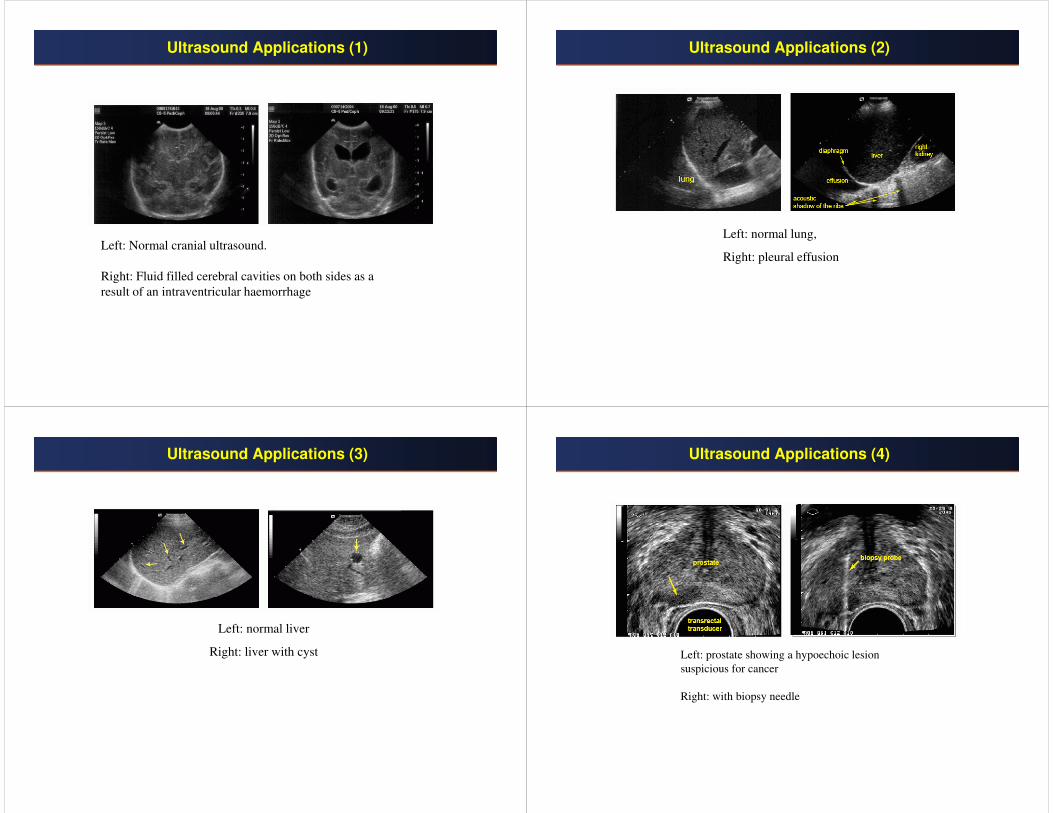
Ultrasound Applications (1)
Left: Normal cranial ultrasound.
Right: Fluid filled cerebral cavities on both sides as a
result of an intraventricular haemorrhage
Ultrasound Applications (2)
Left: normal lung,
Right: pleural effusion
Ultrasound Applications (3)
Left: normal liver
Right: liver with cyst
Ultrasound Applications (4)
Left: prostate showing a hypoechoic lesion
suspicious for cancer
Right: with biopsy needle

Ultrasound Applications (5)
Atrial septal defect (ASD)
Ultrasound Applications (6)
Doppler color flow image of a patient with mitral regurgitation in the left
atrium. The bright green color corresponds to high velocities in mixed
directions, due to very turbulent flow leaking through a small hole in the mitral
valve.