ADVANTAGE SELF STORAGE FACILITY PROSPER … · PROSPER COMMONS BOULEVARD PROSPER, TEXAS ......
24
GEOTECHNICAL ENGINEERING SERVICES REPORT For the proposed ADVANTAGE SELF STORAGE FACILITY AT PROSPER COMMONS LOT 4, BLOCK A PROSPER COMMONS BOULEVARD PROSPER, TEXAS Prepared for RICK JONES COMPANY, LLC 2600 ELDORADO PARKWAY, SUITE 110 MCKINNEY, TX 75070 GTC PROJECT NO. 13G118 August 19, 2013 Prepared by GEOTECHNICAL TESTING AND CONSULTING, LLC 1209 AVENUE N, SUITE 4 PLANO, TEXAS 75074 Telephone (972) 422-0050 Fax (972) 422-0047
Transcript of ADVANTAGE SELF STORAGE FACILITY PROSPER … · PROSPER COMMONS BOULEVARD PROSPER, TEXAS ......
GEOTECHNICAL ENGINEERING SERVICES REPORT
For the proposed
ADVANTAGE SELF STORAGE FACILITY
AT
PROSPER COMMONS LOT 4, BLOCK A PROSPER COMMONS BOULEVARD
PROSPER, TEXAS
Prepared for
RICK JONES COMPANY, LLC 2600 ELDORADO PARKWAY, SUITE 110
MCKINNEY, TX 75070
GTC PROJECT NO. 13G118 August 19, 2013
Prepared by
GEOTECHNICAL TESTING AND CONSULTING, LLC 1209 AVENUE N, SUITE 4
PLANO, TEXAS 75074 Telephone (972) 422-0050
Fax (972) 422-0047
TABLE OF CONTENTS Page No. 1.0 PROJECT AUTHORIZATION AND SCOPE OF SERVICES .......................................... .... 1 2.0 PROJECT AND SITE DESCRIPTION ................................................................................ .... 1 2.1• Project Description .................................................................................................... .... 1
2.2• Site Location and Description .................................................................................. .... 1 3.0 SUBSURFACE CONDITIONS ........................................................................................... .... 2 3.1• Field and Laboratory Testing .................................................................................. .... 2
3.2• Subsurface Conditions ............................................................................................. .... 2 3.3• Groundwater .............................................................................................................. .... 3 4.0 EVALUATION AND RECOMMENDATIONS ............................................................... .... 3 4.1• Vertical Movements ................................................................................................. .... 3 4.2• Site Preparation ........................................................................................................ .... 5 4.3• Foundation Recommendations ................................................................................. .... 6 4.3.1• Monolithic Slab on Grade Foundations .................................................. .... 6 4.3.2• Drilled Pier Foundations .......................................................................... .... 7 4.4• Fill Materials ............................................................................................................ .... 9 4.5• Additional Considerations and Recommendations ................................................ .... 9 4.6• Pavement Recommendations .................................................................................. .... 10 4.6.1• Pavement Subgrade Preparation ............................................................... .... 10 4.6.2• Pavement Design ...................................................................................... .... 10 5.0 CONSTRUCTION CONSIDERATIONS ............................................................................ .... 11 6.0 REPORT LIMITATIONS ...................................................................................................... .... 12 APPENDIX Boring Location Plan Boring Logs Key to Log of Boring
GTC Project No: 13G118 Page 1 of 12
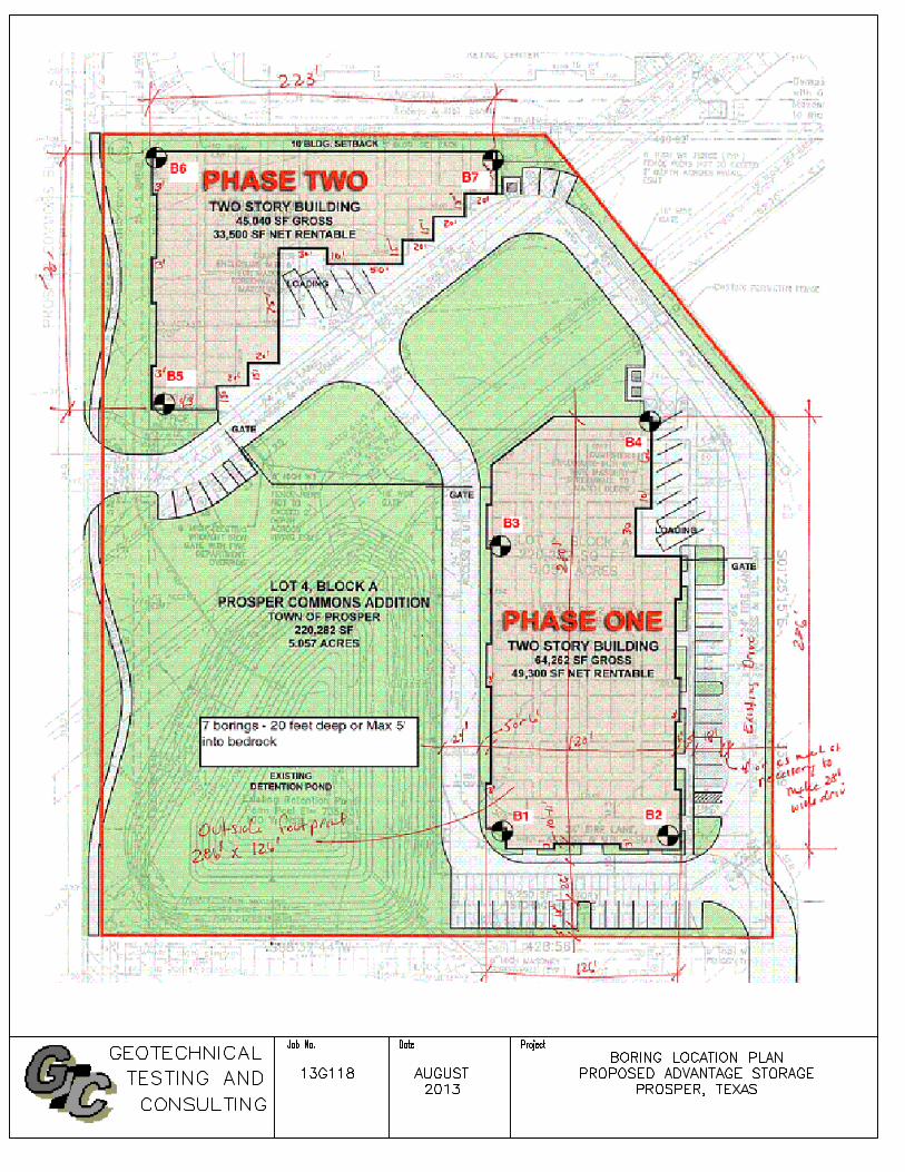
1.0 PROJECT AUTHORIZATION AND SCOPE OF SERVICES The services of Geotechnical Testing and Consulting, LLC (GTC) were authorized on August 2, 2013 by Mr. Brian Baca, V. P. of Rick Jones Company, LLC. by approving our proposal No. 53125 dated July 31, 2013. Our scope of services included drilling 7 soil test borings at the site to depths of approximately 20 feet below the existing ground surface or to a maximum penetration of 5 feet into bedrock, whichever is shallower. Limited laboratory testing of select soil samples to evaluate pertinent physical properties, and to perform engineering analysis to develop foundation design criteria. The scope of services did not include an environmental assessment for determining the presence or absence of wetlands, or hazardous or toxic materials in the soil, bedrock, surface water, groundwater, or air on or below, or around this site. 2.0 PROJECT AND SITE DESCRIPTION 2.1 Project Description It is understood that the proposed project will consist of 2 two story storage buildings, Phase I and Phase II buildings, having footprint areas of 32,131 sft & 22,520 sft. Structural loading information is currently not available, however for the purpose of this proposal it is assumed that maximum wall loads on perimeter grade beams will be less than 2 kips per linear foot and maximum concentrated loads will be less than 40 kips. Based on information provided by Mr. Brian Baca, it is understood that post tensioned slab-on-grade foundation system will be utilized for support of these buildings, however drilled pier foundations may be required to support concentrated loads. Detailed site grading information is not currently available, therefore we have assumed that the buildings will be constructed at or slightly above existing grades. The foundation recommendations presented in this report are based on the available project information, project location, and the subsurface materials described in this report. If any of the noted information is incorrect, please inform GTC in writing so that we may amend the recommendations presented in this report if appropriate and if desired by the client. GTC will not be responsible for the implementation of its recommendations when it is not notified of changes in the project. 2.2 Site Location and Description The proposed project site is a vacant lot located on the east side of Prosper Commons Blvd. north of its intersection with E. University Drive (US Hwy 380) in Prosper, Texas. The project site is bound by a commercial development to the south with E. University Drive beyond, vacant land to the east with a water storage tank to the northeast, vacant land to the north with an apartment complex beyond, and by Prosper Commons Blvd. to the west. At the time of our field activities, a detention pond was located on the southwest quadrant of the site. Surface topography slopes down from northwest to southeast, with a vertical relief of approximately 4 to 5 feet, based on visual observations.
GTC Project No: 13G118 Page 2 of 12
3.0 SUBSURFACE CONDITIONS 3.1 Field and Laboratory Testing The site subsurface conditions were explored with a total of 7 soil test borings advanced to depths of about 15 to 20 feet below the existing ground surface. The approximate boring locations are indicated on the Boring Location Plan enclosed in the Appendix. Copies of the Logs of Borings are also enclosed in the Appendix. The borings were advanced utilizing continuous flight auger drilling methods and soil samples were routinely obtained during the drilling process. Drilling and sampling techniques were accomplished generally in accordance with ASTM procedures. Select soil samples were tested in the laboratory to determine material properties for our evaluation. Laboratory testing was accomplished generally in accordance with ASTM procedures. 3.2 Subsurface Conditions Fill consisting of dark brown clay with weathered limestone fragments was encountered, in four of the seven borings, at the surface and extended to depths of about 2 to 3 feet. Laboratory plasticity tests indicated that samples of this fill soil have liquid limits ranging from 55 to 71 and plasticity indices ranging from 33 to 42. Dark brown clay was encountered at the surface or below the fill and extended to depths ranging from about 1 to 6 feet in all except one boring. Laboratory plasticity tests indicated that these clays have liquid limits in the range of 65 to 70 and plasticity indices in the range of 40 to 43. Tan clay was encountered below the dark brown clay or fills in some of the borings, and extended to depths of about 4 to 8 feet. Laboratory plasticity tests indicated that these clays have liquid limits in the range of 35 to 37 and plasticity indices in the range of 18 to 20. Tan limestone was encountered below the dark brown clay or tan clay in all borings and extended to depths of about 6 to 12 feet. Gray limestone was encountered at depths of 6 to 12 feet in the borings and extended to the boring termination depths of 15 to 20 feet. The above subsurface description is of a generalized nature to highlight the major subsurface stratification features and material characteristics. The boring logs included in the appendix should be reviewed for specific information at individual boring locations. These records include soil/rock descriptions, stratifications, penetration resistances, and locations of the samples and laboratory test data. The stratifications shown on the boring logs represent the conditions only at the actual boring locations. Variations may occur and should be expected between boring locations. The stratifications represent the approximate boundary between subsurface materials and the actual transition may be gradual and indistinct. Water level information obtained during field operations is also shown on these boring logs. The samples, which were not altered by laboratory testing will be retained for 30 days from the date of this report and then will be discarded.
GTC Project No: 13G118 Page 3 of 12
3.3 Groundwater Ground water was not encountered in the borings upon completion of drilling, indicating that the continuous ground water level at the boring locations at the time of the exploration was either below the terminated depths of the borings, or that the soils encountered are relatively impermeable. Although groundwater was not encountered in the borings at this time, it is possible for a groundwater table to be present within the depths explored during other times of the year depending upon climatic and rainfall conditions. The groundwater levels presented in this report are the levels that were measured at the time of our field activities. We recommend that the Contractor determine the actual groundwater levels at the site at the time of the construction activities. 4.0 EVALUATION AND RECOMMENDATIONS 4.1 Vertical Movements Field and laboratory test results indicate that the near surface soils encountered in the borings performed at this site have a high potential for vertical movement (PVM) due to shrinkage and swelling properties of subgrade soils. Based on TXDOT method TEX-124-E and our experience with the shrink/swell characteristics of similar soils, the Potential for Vertical Movement (PVM) is estimated to be in the range of 1 to 3 inches for slab on grade construction at existing grades. However, it should be noted that for extreme conditions (i.e. soils dry and shrink in one area with soils in another area being exposed to water and swelling) differential movement can be equal to or even double the PVM. The estimated PVM values are based on the current site grades. If cut and fill operations are performed, the PVM values could change significantly. If the existing grade is to be raised to attain finish grade elevation, select structural fill should be placed in lifts and properly compacted as recommended under site preparation section of this report. Fill was encountered in some of the borings and extended to depths of about 2 to 3 feet. Information relating to compaction testing during placement of this fill is not available. As is the case with any fill placed without technical observations, the possibility exists that the fill may contain soft spots and concentrated amounts of deleterious material as disclosed by our exploration. Accordingly, there are risks associated with construction on uncontrolled fill. Remedial measures associated with existing/uncontrolled fill would consist of removing the existing fill and either replacing or re-compacting the fill soils under controlled conditions. Remedial measures associated with swelling soils generally consist of either using a structurally suspended floor slab system utilized in conjunction with drilled pier foundation system or reducing the swell potential to an acceptable limit by removing some of the high plasticity soils and replacing them with low swell potential select fill materials. Moisture conditioning of the existing subgrade soils by removing and re-compacting a certain depth of the existing subgrade soils can reduce the required select fill depth.
GTC Project No: 13G118 Page 4 of 12
The most positive remedial measure associated with swelling soils as well as existing fill would consist of a structurally suspended floor slab utilized in conjunction with drilled pier foundation system. Based on information provided by Mr. Brian Baca, it is understood that post tensioned slab-on-grade foundation system will be utilized for support of the building and some concentrated loads may be supported on drilled pier foundations. It is our understanding that differential foundation movements associated with the shrink-swell potential are acceptable to the owner. Consideration should be given to moisture conditioning at least the top 6 feet depth of the building pad subgrade soils or to the top of tan limestone if encountered at shallower depths, in order the reduce the moisture induced potential for Vertical Movement. Moisture conditioning of the top 6 feet depth of subgrade is estimated to reduce the PVM to the order of 1 inch. A 1-foot thick cap of select fill should be placed on top of the moisture conditioned soils to prevent drying during construction. A below surface moisture barrier, consisting of minimum 6 mil polyethylene sheeting, may be used in place of select fill to prevent drying during construction. Any additional fill required to achieve final grade should consist of select fill. The performance of a slab on grade foundation can be significantly influenced by yard maintenance, recessed landscaping additions near the building, utility leaks and any other free water sources, and deep-rooted trees and shrubs. Deep-rooted trees and shrubs located near the structure, within an approximate distance equal to about their ultimate mature height, could cause foundation settlement due to ground shrinkage as a result of long-term moisture absorption of the roots. It is also imperative that moist soil conditions be maintained within 10 feet of the foundation perimeter during prolonged periods of dry weather to prevent deep desiccation crack development and associated settlement due to ground shrinkage. Providing flatwork around the buildings will help in reducing moisture variation under the buildings, increasing the depth of building perimeter grade beams (suggested minimum depth of 3 feet or more) also reduces moisture variation below the building foundation. The following design recommendations have been developed on the basis of the previously described project characteristics and subsurface conditions encountered. If there are any changes in these project criteria, including project location on the site, a review must be made by GTC to determine if any modifications in the recommendations will be required. Once final design plans and specifications are available a general review by GTC is strongly recommended as a means to check that the evaluations made in preparation of this report are correct and that the earthwork and foundation recommendations are properly interpreted and implemented.
GTC Project No: 13G118 Page 5 of 12
4.2 Site Preparation To reduce the potential for moisture induced movement of the site soils, it is important that consideration is given to reducing the potential for moisture changes of the site soils. As a minimum, positive drainage away from the building should be provided. If positive drainage is not provided, water will pond around or below the building and excessive total and differential movements may occur. Initially, all topsoil, existing fill and deleterious materials must be removed from the areas proposed for construction. After stripping excavate to a depth of 6 feet below the existing grade, or to the top of tan limestone if encountered at shallower depth. The exposed building subgrade should then be proof-rolled with a tandem axle dump truck or similar rubber tired vehicle. Soils, which are observed to rut or deflect excessively under the moving load, should be undercut and replaced with properly compacted fill. The proof-rolling and undercutting activities should be witnessed by a representative of the geotechnical engineer and should be performed during a period of dry weather. The subgrade soils should then be scarified and re-compacted to within 93% to 98% of the standard Proctor maximum dry density ASTM D698, in the moisture range of at least 4% or more above optimum, for a depth of at least 8 inches below the surface. After preparing the exposed subgrade as described above, backfill to the proposed floor slab subgrade elevation using on-site excavated soils. This on-site moisture conditioned fill should be compacted to between 93 to 98 percent of the standard Proctor maximum dry density ASTM D698, in the moisture range of at least 4% or more above optimum. Undercut and backfill of moisture conditioned fill should extend horizontally at least five feet beyond the perimeter of the building. Each lift of compacted-moisture conditioned fill should be tested by a representative of the geotechnical engineer prior to placement of subsequent lifts. All back fill materials should be free of organic or other deleterious materials, have a maximum particle/clod size less than 3 inches. All fill should be placed in maximum lifts of 8 inches of loose material. Each lift of compacted-engineered fill should be tested by a representative of the Geotechnical engineer prior to placement of subsequent lifts. A moisture barrier should be placed on top of the moisture conditioned subgrade to prevent drying during construction. The moisture barrier should consist of a 12-inch thick cap of properly select fill compacted to at least 95 percent of standard Proctor maximum dry density as determined by ASTM Designation D 698 in the moisture range of optimum to 4 percentage points above the optimum moisture content value. Select fill should extend only to the building perimeter and all fill outside the building perimeter should consist on on-site clay fill. As an alternate to the use of select fill, a below surface moisture barrier, consisting of minimum 6 mil polyethylene sheeting, may be used. The moisture barrier should be placed 12-inches below the surface and should extend a minimum of 5 feet beyond the perimeter of the building slab and foundation.
GTC Project No: 13G118 Page 6 of 12
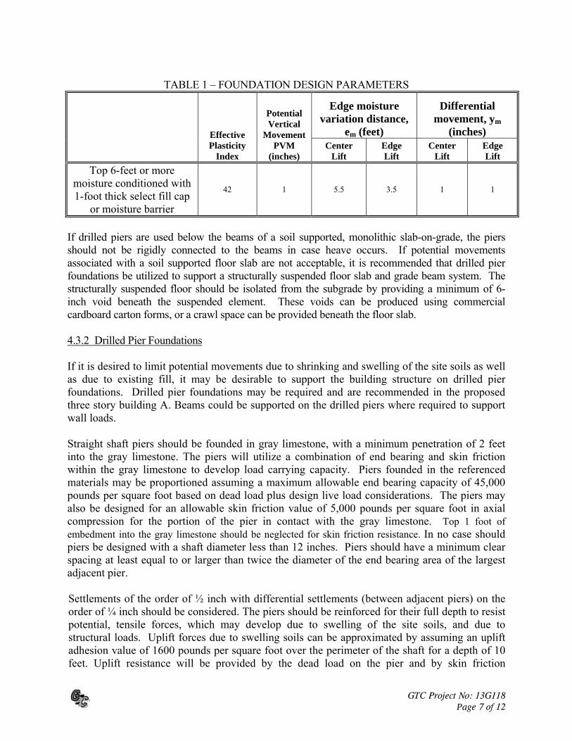
4.3 Foundation Recommendations If some differential movement can be tolerated, a monolithic slab on grade supported on modified subgrade, may be considered as one option for building foundation. If the referenced movements are not acceptable, consideration should be given to supporting the building structure on a drilled pier foundation system with a structurally suspended floor slab. 4.3.1 Monolithic Slab on Grade Foundations The foundation system may consist of a monolithic grid type grade beam and slab reinforced with conventional and/or post-tensioned reinforcing, provided that expected total and differential movements can be tolerated. The foundation should be designed with exterior and interior grade beams to provide adequate rigidity to the foundation system to sustain the vertical soil movements expected at this site. Grade beams bearing on properly compacted on-site clays, may be designed using a net allowable bearing capacity of 1500 pounds per square foot. The grade beams should have a minimum width of 10 inches, even if the actual bearing pressure is less than the design value. The grade beams should be extended at least 24 inches below adjacent surface grades. Consideration should be given to extending the perimeter grade beams deeper (3-feet or more), particularly in areas where flatwork does not abut the building perimeter. If soft or loose soils are encountered at the design bearing level, they should be undercut to stiff or dense soils and the excavation backfilled with low swell potential fill or concrete. It is important that the beams be excavated, bearing soils observed by the geotechnical engineer or his representative, formwork and reinforcing steel and/or cables installed, and concrete placed as quickly as possible. Extreme care should be taken to prevent the weakening of the foundation bearing materials because of prolonged atmospheric exposure, construction activity disturbance or an increase in moisture content. Leaving foundation excavations open overnight is not recommended. If foundation excavations are to remain open for more than one day, they should be adequately protected to reduce evaporation or entry of moisture. A moisture barrier of polyethylene sheeting or similar material should be placed between the slab and the subgrade soils to retard moisture migration through the slab. It should be understood, by all parties, that a soil-supported foundation system will experience movement with time, however, with proper design, construction and maintenance, the magnitude of the movement can be kept to a manageable level. Foundation design criteria for use with Post tensioned Foundation Design based on Post Tensioning Institute’s (PTI) manual are given in Table 1 below. Also included in the table below is information for use in conventionally reinforced slab-on grade foundation.
GTC Project No: 13G118 Page 7 of 12
TABLE 1 – FOUNDATION DESIGN PARAMETERS
Effective Plasticity
Index
Potential Vertical
Movement PVM
(inches)
Edge moisture variation distance,
em (feet)
Differential movement, ym
(inches) Center
Lift Edge Lift
Center Lift
Edge Lift
Top 6-feet or more moisture conditioned with 1-foot thick select fill cap
or moisture barrier
42 1 5.5 3.5 1 1
If drilled piers are used below the beams of a soil supported, monolithic slab-on-grade, the piers should not be rigidly connected to the beams in case heave occurs. If potential movements associated with a soil supported floor slab are not acceptable, it is recommended that drilled pier foundations be utilized to support a structurally suspended floor slab and grade beam system. The structurally suspended floor should be isolated from the subgrade by providing a minimum of 6-inch void beneath the suspended element. These voids can be produced using commercial cardboard carton forms, or a crawl space can be provided beneath the floor slab. 4.3.2 Drilled Pier Foundations If it is desired to limit potential movements due to shrinking and swelling of the site soils as well as due to existing fill, it may be desirable to support the building structure on drilled pier foundations. Drilled pier foundations may be required and are recommended in the proposed three story building A. Beams could be supported on the drilled piers where required to support wall loads. Straight shaft piers should be founded in gray limestone, with a minimum penetration of 2 feet into the gray limestone. The piers will utilize a combination of end bearing and skin friction within the gray limestone to develop load carrying capacity. Piers founded in the referenced materials may be proportioned assuming a maximum allowable end bearing capacity of 45,000 pounds per square foot based on dead load plus design live load considerations. The piers may also be designed for an allowable skin friction value of 5,000 pounds per square foot in axial compression for the portion of the pier in contact with the gray limestone. Top 1 foot of embedment into the gray limestone should be neglected for skin friction resistance. In no case should piers be designed with a shaft diameter less than 12 inches. Piers should have a minimum clear spacing at least equal to or larger than twice the diameter of the end bearing area of the largest adjacent pier. Settlements of the order of ½ inch with differential settlements (between adjacent piers) on the order of ¼ inch should be considered. The piers should be reinforced for their full depth to resist potential, tensile forces, which may develop due to swelling of the site soils, and due to structural loads. Uplift forces due to swelling soils can be approximated by assuming an uplift adhesion value of 1600 pounds per square foot over the perimeter of the shaft for a depth of 10 feet. Uplift resistance will be provided by the dead load on the pier and by skin friction
GTC Project No: 13G118 Page 8 of 12
resistance within the limestone. Resistance to uplift can be calculated using an allowable skin friction value of 3500 psf for the portion of the pier in contact with the gray limestone. It is recommended that the design and construction of drilled piers should generally follow methods outlined in the manual titled Drilled Shafts: Construction Procedures and Design Methods (Publication No: FHWA-IF-99-025, August 1999). Detailed inspection of pier construction should be made to verify that the piers are vertical and founded in the proper bearing stratum, and to verify that all loose materials have been removed prior to concrete placement. Temporary casing must be used where necessary to stabilize pier holes and to control water inflow. Any accumulated water must be removed prior to the placement of concrete. A hopper and tremie should be utilized during concrete placement to control the maximum free fall of the wet concrete to less than five feet unless the mix is designed so that it does not segregate during free fall and provided the pier excavation is dry. If the pier hole has been cased, sufficient concrete should remain in the casing as the casing is withdrawn to prevent any discontinuities from forming within the concrete section. Concrete placed in drilled piers should be placed at slumps between six to eight inches. Concrete, which is placed in piers at a slump less than six inches, increases the potential for honeycombing. Concrete used in piers should be designed to achieve the required strength at the higher slumps as referenced above. For any given pier, excavation, placement of steel and concreting should be completed within the same workday. Where water inflow or caving soils are encountered, excavation of piers and placement of concrete within a very short time frame will frequently aid in proper pier construction. Structurally supported grade beams, pier caps if required, should be isolated from the subgrade soils by providing a minimum 6-inch positive void beneath the floor slab, grade beams and pier caps. Void forms will not be required for pier supported monolithic slab on grade foundation system. Voids can be produced using compressible cardboard carton forms specially manufactured for this purpose. Care should be exercised so that the forms are not crushed, damaged or saturated prior to placement of the concrete. In addition, barriers that will not rapidly decay should be placed or constructed along the sides of the cardboard carton forms to prevent soil intrusion into the void after the carton forms decay.
GTC Project No: 13G118 Page 9 of 12
4.4 Fill Materials All fill should be free of organic or other deleterious materials and should have a maximum particle size of 3 inches. Low swell potential “select” fill should have a maximum liquid limit of 35 and plasticity index between 5 and 15. Fill should be placed in maximum 8-inch loose lifts, Select fill should be compacted to a minimum of 95 percent of the maximum dry density as determined by ASTM D 698 (Standard Proctor) in the moisture range of optimum to 4 percent above the optimum value as defined by ASTM D 698. The on-site moisture conditioned fill should be compacted to between 93 to 98 percent of the standard Proctor maximum dry density ASTM D698, in the moisture range of at least 4% or more above optimum. 4.5 Additional Considerations and Recommendations The following information has been developed after review of numerous problems concerning foundations throughout the area. It is presented here for your convenience. If these features are incorporated in the overall design and specifications for the project, performance of the project will be improved. 1. Prior to construction, the area to be covered by buildings should be prepared so that
water will not pond beneath or around the buildings after periods of rainfall. In addition, water should not be allowed to pond on or around pavements.
2. Roof drainage should be collected and transmitted by pipe to a storm drainage system or to
an area where the water can drain away from buildings and pavements without entering the soils supporting buildings and pavements.
3. Sidewalks should not be structurally connected to buildings. They should be sloped away
from buildings so that water will be drained away from structures. 4. Paved areas and the general ground surface should be sloped away from buildings on all
sides so that water will always drain away from the structures. Water should not be allowed to pond near buildings after the floor slabs and foundations have been constructed.
5. Backfill for utility lines that are located in pavement, sidewalk and building areas should
consist of low swell potential fill. The backfill should be compacted as described in the "Fill Material" section of this report. Lesser lift thickness may be required to obtain adequate compaction.
6. Care should be exercised to make sure that ditches for utility lines do not serve as conduits
that transmit water beneath structures or pavements. The top of the ditch should be sealed to inhibit the inflow of surface water during periods of rainfall.
GTC Project No: 13G118 Page 10 of 12
7. Flower beds and planting areas should not be constructed along building perimeters. Constructing sidewalks or pavements adjacent to buildings would be preferable. If required, flower beds and planting areas could be constructed beyond the sidewalks away from the buildings. If it is desired to have flower beds and planting areas adjacent to a building, the use of above grade concrete box planters, or other methods which reduce the likelihood of large changes in moisture content of soils adjacent to or below structures should be considered.
8. Water sprinkling systems should not be located where water will be sprayed onto building
walls and subsequently drain downward and flow into the soils beneath foundations. 9. Trees in general, should not be planted closer to a structure than the mature height of the
tree. A tree planted closer to a structure than the recommended distance may extend its roots beneath the structure, allowing removal of subgrade moisture and/or causing structural distress.
10. Utilities which project through slab-on-grade floors, particularly where expansive soils or
soils subject to settlement are present, should be designed with some degree of flexibility and/or with a sleeve to reduce the potential for damage to the utilities should movement occur.
4.6 Pavement Recommendations 4.6.1 Pavement Subgrade Preparation Where rigid concrete pavement is used, lime stabilization of the subgrade soils will not be necessary and the pavement can be placed on properly compacted subgrade. It is our understanding that flexible (Asphalt) pavement sections are not planned. It should be noted that lime stabilization of the pavement subgrade will improve the subgrade strength and pavement performance. However the pavement design presented below is based on a non-lime stabilized subgrade. If the subgrade is stabilized with lime the pavement thicknesses presented below can be reduced. If lime stabilization is considered, soluble sulfate content of the subgrade soils should be checked prior to stabilization. The subgrade soils should be scarified and re-compacted to at least 95 percent of the standard Proctor maximum dry density ASTM D698, in the moisture range of optimum to 4% above optimum, for a depth of at least 6 inches below the surface. Any fill required to achieve final grade may consist of on-site soils and should be compacted to at least 95 percent of the standard Proctor maximum dry density ASTM D698, in the moisture range of optimum to 4% above optimum. 4.6.2 Pavement Design The design thickness of a pavement will depend on the magnitude of axle loads and the number of load repetitions. Parking and drive areas will be constructed at locations around the buildings. Based on traffic information provided by Mr. Brian Baca, we understand that the drives and fire lanes will be subjected to maximum average daily traffic (ADT) of about 100 vehicles per day.
GTC Project No: 13G118 Page 11 of 12
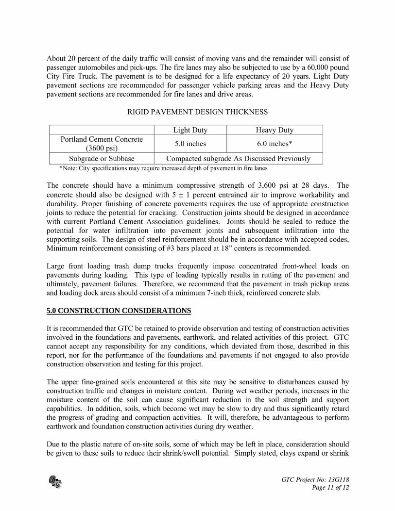
About 20 percent of the daily traffic will consist of moving vans and the remainder will consist of passenger automobiles and pick-ups. The fire lanes may also be subjected to use by a 60,000 pound City Fire Truck. The pavement is to be designed for a life expectancy of 20 years. Light Duty pavement sections are recommended for passenger vehicle parking areas and the Heavy Duty pavement sections are recommended for fire lanes and drive areas.
RIGID PAVEMENT DESIGN THICKNESS
Light Duty Heavy Duty Portland Cement Concrete
(3600 psi) 5.0 inches 6.0 inches*
Subgrade or Subbase Compacted subgrade As Discussed Previously *Note: City specifications may require increased depth of pavement in fire lanes The concrete should have a minimum compressive strength of 3,600 psi at 28 days. The concrete should also be designed with 5 1 percent entrained air to improve workability and durability. Proper finishing of concrete pavements requires the use of appropriate construction joints to reduce the potential for cracking. Construction joints should be designed in accordance with current Portland Cement Association guidelines. Joints should be sealed to reduce the potential for water infiltration into pavement joints and subsequent infiltration into the supporting soils. The design of steel reinforcement should be in accordance with accepted codes, Minimum reinforcement consisting of #3 bars placed at 18” centers is recommended. Large front loading trash dump trucks frequently impose concentrated front-wheel loads on pavements during loading. This type of loading typically results in rutting of the pavement and ultimately, pavement failures. Therefore, we recommend that the pavement in trash pickup areas and loading dock areas should consist of a minimum 7-inch thick, reinforced concrete slab. 5.0 CONSTRUCTION CONSIDERATIONS It is recommended that GTC be retained to provide observation and testing of construction activities involved in the foundations and pavements, earthwork, and related activities of this project. GTC cannot accept any responsibility for any conditions, which deviated from those, described in this report, nor for the performance of the foundations and pavements if not engaged to also provide construction observation and testing for this project. The upper fine-grained soils encountered at this site may be sensitive to disturbances caused by construction traffic and changes in moisture content. During wet weather periods, increases in the moisture content of the soil can cause significant reduction in the soil strength and support capabilities. In addition, soils, which become wet may be slow to dry and thus significantly retard the progress of grading and compaction activities. It will, therefore, be advantageous to perform earthwork and foundation construction activities during dry weather. Due to the plastic nature of on-site soils, some of which may be left in place, consideration should be given to these soils to reduce their shrink/swell potential. Simply stated, clays expand or shrink
GTC Project No: 13G118 Page 12 of 12
by absorbing or losing moisture. Controlling the moisture content variation of a soil will therefore reduce its variation in volume. During construction, a positive surface drainage scheme should be implemented to prevent ponding of water on the subgrade. The pavement subgrades should not be allowed to dry out during construction. Drainage from the buildings roof/gutter system should not be allowed to drain and/or pond behind the pavement curbs. 6.0 REPORT LIMITATIONS The recommendations submitted, in this report, are based on the available subsurface information obtained by GTC and design details furnished by the client. If there are any revisions to the plans for this project, or if deviations from the subsurface conditions noted in this report are encountered during construction, GTC should be notified immediately to determine if changes in the foundation recommendations are required. If GTC is not notified of such changes, GTC will not be responsible for the impact of those changes on the project. The geotechnical engineer warrants that the findings, recommendations, specifications, or professional advice contained herein have been made in accordance with generally accepted professional geotechnical engineering practices in the local area. No other warranties are implied or expressed. After the plans and specifications are more complete, the geotechnical engineer should be retained and provided the opportunity to review the final design plans and specifications to check that our engineering recommendations have been properly incorporated into the design documents. At this time, it may be necessary to submit supplementary recommendations. If GTC is not retained to perform these functions, GTC will not be responsible for the impact of those conditions on the project. This report has been prepared for the exclusive use of our client Rick Jones Company, LLC. for the specific application to this project. GTC is not responsible for conclusions, opinions or recommendations made by others based on data contained in this report.

APPENDIX
C:\
GT
C D
ocu
me
nts
\GT
C R
ep
ort
s\2
01
2_
20
13
Re
po
rts\
13
G1
18
Ad
van
tag
e S
tora
ge
Pro
spe
r\L
og
s13
G1
18
.bg
s [G
TC
Lo
g -
7 L
ab
.tp
l]
Figure
Sheet 1 of 1
Project: Advantage Storage
Project Location: Prosper, Texas
GTC Project Number: 13G118
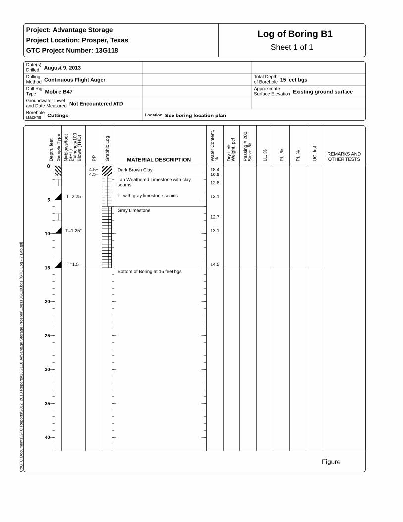
Log of Boring B1
Date(s) Drilled August 9, 2013
Drilling Method Continuous Flight Auger
Drill Rig Type Mobile B47
Groundwater Level and Date Measured Not Encountered ATD
Borehole Backfill Cuttings
Location See boring location plan
Total Depth of Borehole 15 feet bgs
Approximate Surface Elevation Existing ground surface
0
5
10
15
20
25
30
35
40
Dep
th,
feet
Sam
ple
Typ
e
N=
blow
s/fo
ot(S
PT
) T
=In
ches
/100
Blo
ws
(TH
D)
PP
Gra
phic
Log
MATERIAL DESCRIPTION Wat
er C
onte
nt,
% Dry
Un
itW
eigh
t, p
cf
Pas
sing
# 2
00S
ieve
, %
LL,
%
PL,
%
PI,
%
UC
, ks
f
REMARKS AND OTHER TESTS
Dark Brown Clay
Tan Weathered Limestone with clay seams
with gray limestone seams
Gray Limestone
Bottom of Boring at 15 feet bgs
4.5+ 18.44.5+ 16.9
12.8
T=2.25 13.1
12.7
T=1.25" 13.1
T=1.5" 14.5

C:\
GT
C D
ocu
me
nts
\GT
C R
ep
ort
s\2
01
2_
20
13
Re
po
rts\
13
G1
18
Ad
van
tag
e S
tora
ge
Pro
spe
r\L
og
s13
G1
18
.bg
s [G
TC
Lo
g -
7 L
ab
.tp
l]
Figure
Sheet 1 of 1
Project: Advantage Storage
Project Location: Prosper, Texas
GTC Project Number: 13G118
Log of Boring B2
Date(s) Drilled August 9, 2013
Drilling Method Continuous Flight Auger
Drill Rig Type Mobile B47
Groundwater Level and Date Measured Not Encountered ATD
Borehole Backfill Cuttings
Location See boring location plan
Total Depth of Borehole 20 feet bgs
Approximate Surface Elevation Existing ground surface
0
5
10
15
20
25
30
35
40
Dep
th,
feet
Sam
ple
Typ
e
N=
blow
s/fo
ot(S
PT
) T
=In
ches
/100
Blo
ws
(TH
D)
PP
Gra
phic
Log
MATERIAL DESCRIPTION Wat
er C
onte
nt,
% Dry
Un
itW
eigh
t, p
cf
Pas
sing
# 2
00S
ieve
, %
LL,
%
PL,
%
PI,
%
UC
, ks
f
REMARKS AND OTHER TESTS
Dark Brown Clay
Tan Clay
Tan Weathered Limestone
Gray Limestone
Bottom of Boring at 20 feet bgs
4.5+ 21.94.5+ 20.2 88 65 25 40
4.5+ 14.5
4.5+ 18.6
T=2.5" 15.9
14.3
T=1.5" 12.4
T=1.5" 12.6
T=1.25" 12.4
C:\
GT
C D
ocu
me
nts
\GT
C R
ep
ort
s\2
01
2_
20
13
Re
po
rts\
13
G1
18
Ad
van
tag
e S
tora
ge
Pro
spe
r\L
og
s13
G1
18
.bg
s [G
TC
Lo
g -
7 L
ab
.tp
l]
Figure
Sheet 1 of 1
Project: Advantage Storage
Project Location: Prosper, Texas
GTC Project Number: 13G118
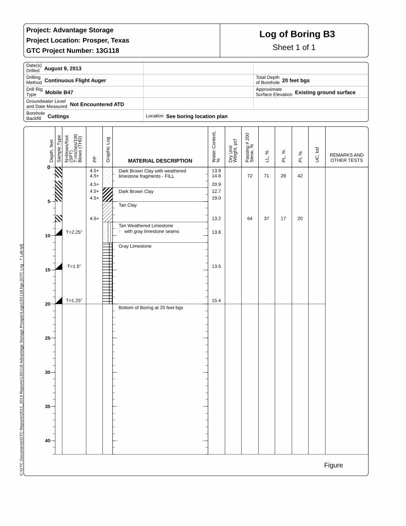
Log of Boring B3
Date(s) Drilled August 9, 2013
Drilling Method Continuous Flight Auger
Drill Rig Type Mobile B47
Groundwater Level and Date Measured Not Encountered ATD
Borehole Backfill Cuttings
Location See boring location plan
Total Depth of Borehole 20 feet bgs
Approximate Surface Elevation Existing ground surface
0
5
10
15
20
25
30
35
40
Dep
th,
feet
Sam
ple
Typ
e
N=
blow
s/fo
ot(S
PT
) T
=In
ches
/100
Blo
ws
(TH
D)
PP
Gra
phic
Log
MATERIAL DESCRIPTION Wat
er C
onte
nt,
% Dry
Un
itW
eigh
t, p
cf
Pas
sing
# 2
00S
ieve
, %
LL,
%
PL,
%
PI,
%
UC
, ks
f
REMARKS AND OTHER TESTS
Dark Brown Clay with weathered limestone fragments - FILL
Dark Brown Clay
Tan Clay
Tan Weathered Limestone
with gray limestone seams
Gray Limestone
Bottom of Boring at 20 feet bgs
4.5+ 13.94.5+ 14.6 72 71 29 42
4.5+ 20.9
4.5+ 12.7
4.5+ 19.0
4.5+ 13.2 64 37 17 20
T=2.25" 13.8
T=1.5" 13.5
T=1.25" 15.4

C:\
GT
C D
ocu
me
nts
\GT
C R
ep
ort
s\2
01
2_
20
13
Re
po
rts\
13
G1
18
Ad
van
tag
e S
tora
ge
Pro
spe
r\L
og
s13
G1
18
.bg
s [G
TC
Lo
g -
7 L
ab
.tp
l]
Figure
Sheet 1 of 1
Project: Advantage Storage
Project Location: Prosper, Texas
GTC Project Number: 13G118
Log of Boring B4
Date(s) Drilled August 9, 2013
Drilling Method Continuous Flight Auger
Drill Rig Type Mobile B47
Groundwater Level and Date Measured Not Encountered ATD
Borehole Backfill Cuttings
Location See boring location plan
Total Depth of Borehole 20 feet bgs
Approximate Surface Elevation Existing ground surface
0
5
10
15
20
25
30
35
40
Dep
th,
feet
Sam
ple
Typ
e
N=
blow
s/fo
ot(S
PT
) T
=In
ches
/100
Blo
ws
(TH
D)
PP
Gra
phic
Log
MATERIAL DESCRIPTION Wat
er C
onte
nt,
% Dry
Un
itW
eigh
t, p
cf
Pas
sing
# 2
00S
ieve
, %
LL,
%
PL,
%
PI,
%
UC
, ks
f
REMARKS AND OTHER TESTS
Dark Brown Clay with weathered limestone fragments - FILL
Dark Brown Clay
Tan Clay
Tan Weathered Limestone
with gray limestone seams
Gray Limestone
Bottom of Boring at 20 feet bgs
4.5+ 13.04.5+ 22.0
4.5+ 22.4 93 70 27 43
4.5+ 20.9
4.5+ 18.5
15.0
T=2" 16.1
T=2" 13.1
T=1.25" 13.0
C:\
GT
C D
ocu
me
nts
\GT
C R
ep
ort
s\2
01
2_
20
13
Re
po
rts\
13
G1
18
Ad
van
tag
e S
tora
ge
Pro
spe
r\L
og
s13
G1
18
.bg
s [G
TC
Lo
g -
7 L
ab
.tp
l]
Figure
Sheet 1 of 1
Project: Advantage Storage
Project Location: Prosper, Texas
GTC Project Number: 13G118
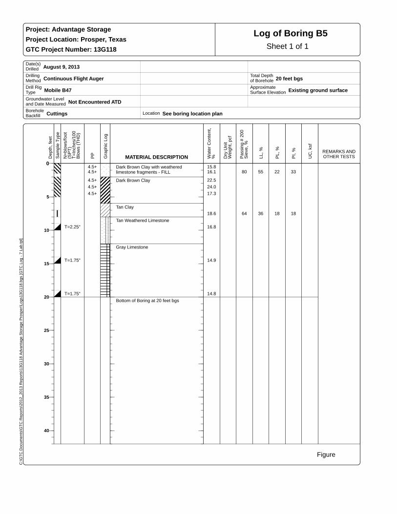
Log of Boring B5
Date(s) Drilled August 9, 2013
Drilling Method Continuous Flight Auger
Drill Rig Type Mobile B47
Groundwater Level and Date Measured Not Encountered ATD
Borehole Backfill Cuttings
Location See boring location plan
Total Depth of Borehole 20 feet bgs
Approximate Surface Elevation Existing ground surface
0
5
10
15
20
25
30
35
40
Dep
th,
feet
Sam
ple
Typ
e
N=
blow
s/fo
ot(S
PT
) T
=In
ches
/100
Blo
ws
(TH
D)
PP
Gra
phic
Log
MATERIAL DESCRIPTION Wat
er C
onte
nt,
% Dry
Un
itW
eigh
t, p
cf
Pas
sing
# 2
00S
ieve
, %
LL,
%
PL,
%
PI,
%
UC
, ks
f
REMARKS AND OTHER TESTS
Dark Brown Clay with weathered limestone fragments - FILL
Dark Brown Clay
Tan Clay
Tan Weathered Limestone
Gray Limestone
Bottom of Boring at 20 feet bgs
4.5+ 15.84.5+ 16.1 80 55 22 33
4.5+ 22.5
4.5+ 24.0
4.5+ 17.3
18.6 64 36 18 18
T=2.25" 16.8
T=1.75" 14.9
T=1.75" 14.8
C:\
GT
C D
ocu
me
nts
\GT
C R
ep
ort
s\2
01
2_
20
13
Re
po
rts\
13
G1
18
Ad
van
tag
e S
tora
ge
Pro
spe
r\L
og
s13
G1
18
.bg
s [G
TC
Lo
g -
7 L
ab
.tp
l]
Figure
Sheet 1 of 1
Project: Advantage Storage
Project Location: Prosper, Texas
GTC Project Number: 13G118
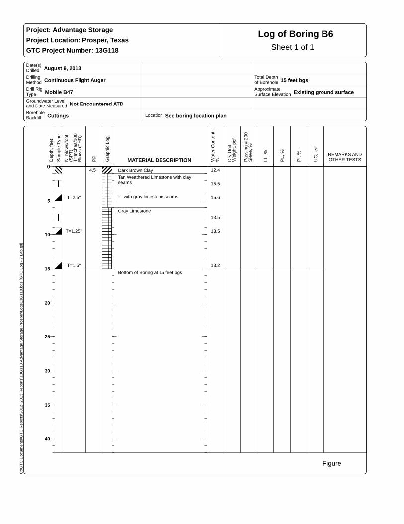
Log of Boring B6
Date(s) Drilled August 9, 2013
Drilling Method Continuous Flight Auger
Drill Rig Type Mobile B47
Groundwater Level and Date Measured Not Encountered ATD
Borehole Backfill Cuttings
Location See boring location plan
Total Depth of Borehole 15 feet bgs
Approximate Surface Elevation Existing ground surface
0
5
10
15
20
25
30
35
40
Dep
th,
feet
Sam
ple
Typ
e
N=
blow
s/fo
ot(S
PT
) T
=In
ches
/100
Blo
ws
(TH
D)
PP
Gra
phic
Log
MATERIAL DESCRIPTION Wat
er C
onte
nt,
% Dry
Un
itW
eigh
t, p
cf
Pas
sing
# 2
00S
ieve
, %
LL,
%
PL,
%
PI,
%
UC
, ks
f
REMARKS AND OTHER TESTS
Dark Brown Clay Tan Weathered Limestone with clay
seams
with gray limestone seams
Gray Limestone
Bottom of Boring at 15 feet bgs
4.5+ 12.4
15.5
T=2.5" 15.6
13.5
T=1.25" 13.5
T=1.5" 13.2
C:\
GT
C D
ocu
me
nts
\GT
C R
ep
ort
s\2
01
2_
20
13
Re
po
rts\
13
G1
18
Ad
van
tag
e S
tora
ge
Pro
spe
r\L
og
s13
G1
18
.bg
s [G
TC
Lo
g -
7 L
ab
.tp
l]
Figure
Sheet 1 of 1
Project: Advantage Storage
Project Location: Prosper, Texas
GTC Project Number: 13G118
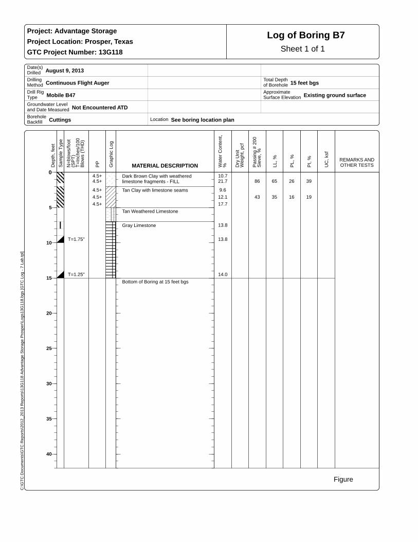
Log of Boring B7
Date(s) Drilled August 9, 2013
Drilling Method Continuous Flight Auger
Drill Rig Type Mobile B47
Groundwater Level and Date Measured Not Encountered ATD
Borehole Backfill Cuttings
Location See boring location plan
Total Depth of Borehole 15 feet bgs
Approximate Surface Elevation Existing ground surface
0
5
10
15
20
25
30
35
40
Dep
th,
feet
Sam
ple
Typ
e
N=
blow
s/fo
ot(S
PT
) T
=In
ches
/100
Blo
ws
(TH
D)
PP
Gra
phic
Log
MATERIAL DESCRIPTION Wat
er C
onte
nt,
% Dry
Un
itW
eigh
t, p
cf
Pas
sing
# 2
00S
ieve
, %
LL,
%
PL,
%
PI,
%
UC
, ks
f
REMARKS AND OTHER TESTS
Dark Brown Clay with weathered limestone fragments - FILL
Tan Clay with limestone seams
Tan Weathered Limestone
Gray Limestone
Bottom of Boring at 15 feet bgs
4.5+ 10.74.5+ 21.7 86 65 26 39
4.5+ 9.6
4.5+ 12.1 43 35 16 19
4.5+ 17.7
13.8
T=1.75" 13.8
T=1.25" 14.0
C:\
GT
C D
ocu
me
nts
\GT
C R
ep
ort
s\2
01
2_
20
13
Re
po
rts\
13
G1
18
Ad
van
tag
e S
tora
ge
Pro
spe
r\L
og
s13
G1
18
.bg
s [G
TC
Lo
g -
7 L
ab
.tp
l]
Sheet 1 of 1
Project: Advantage Storage
Project Location: Prosper, Texas
Project Number: 13G118
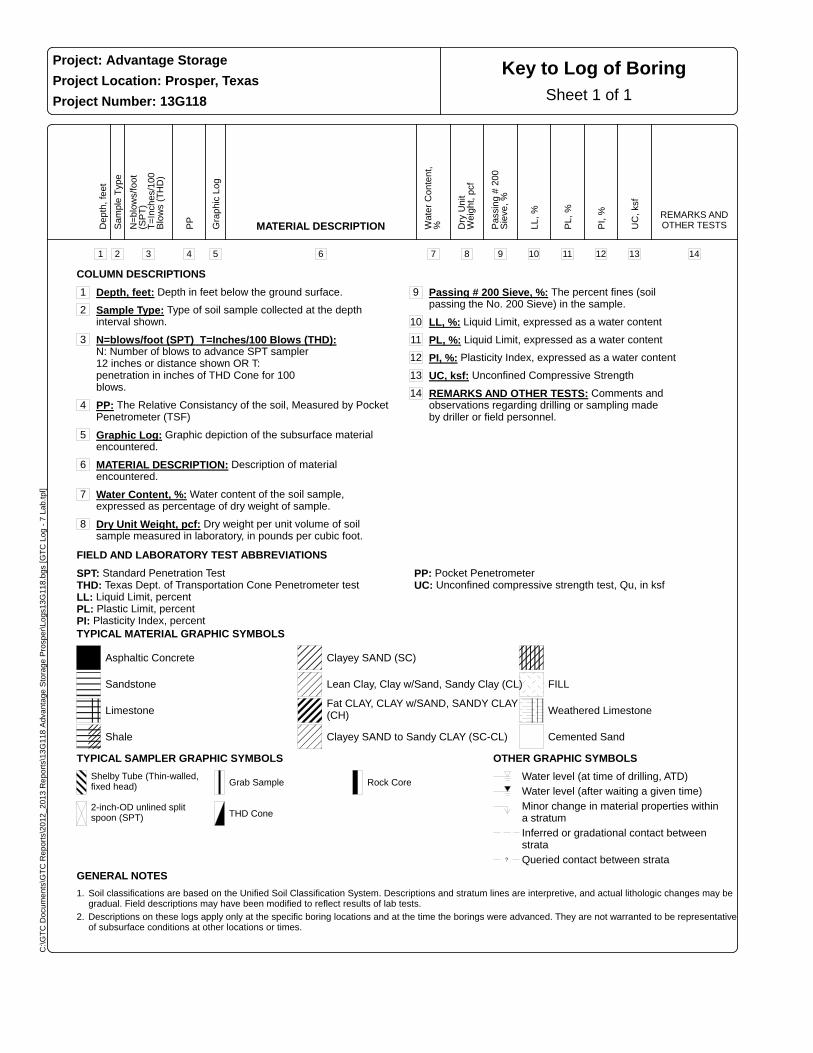
Key to Log of Boring
COLUMN DESCRIPTIONS
1 Depth, feet: Depth in feet below the ground surface.
2 Sample Type: Type of soil sample collected at the depth interval shown.
3 N=blows/foot (SPT) T=Inches/100 Blows (THD): N: Number of blows to advance SPT sampler 12 inches or distance shown OR T: penetration in inches of THD Cone for 100 blows.
4 PP: The Relative Consistancy of the soil, Measured by Pocket Penetrometer (TSF)
5 Graphic Log: Graphic depiction of the subsurface material encountered.
6 MATERIAL DESCRIPTION: Description of material encountered.
7 Water Content, %: Water content of the soil sample, expressed as percentage of dry weight of sample.
8 Dry Unit Weight, pcf: Dry weight per unit volume of soil sample measured in laboratory, in pounds per cubic foot.
9 Passing # 200 Sieve, %: The percent fines (soil passing the No. 200 Sieve) in the sample.
10 LL, %: Liquid Limit, expressed as a water content
11 PL, %: Liquid Limit, expressed as a water content
12 PI, %: Plasticity Index, expressed as a water content
13 UC, ksf: Unconfined Compressive Strength
14 REMARKS AND OTHER TESTS: Comments and observations regarding drilling or sampling made by driller or field personnel.
FIELD AND LABORATORY TEST ABBREVIATIONS
SPT: Standard Penetration TestTHD: Texas Dept. of Transportation Cone Penetrometer testLL: Liquid Limit, percentPL: Plastic Limit, percentPI: Plasticity Index, percent
PP: Pocket PenetrometerUC: Unconfined compressive strength test, Qu, in ksf
TYPICAL MATERIAL GRAPHIC SYMBOLS
Asphaltic Concrete
Sandstone
Limestone
Shale
Clayey SAND (SC)
Lean Clay, Clay w/Sand, Sandy Clay (CL)
Fat CLAY, CLAY w/SAND, SANDY CLAY (CH)
Clayey SAND to Sandy CLAY (SC-CL)
FILL
Weathered Limestone
Cemented Sand
TYPICAL SAMPLER GRAPHIC SYMBOLS
Shelby Tube (Thin-walled, fixed head)
2-inch-OD unlined split spoon (SPT)
Grab Sample
THD Cone
Rock Core
OTHER GRAPHIC SYMBOLS
Water level (at time of drilling, ATD)
Water level (after waiting a given time)
Minor change in material properties within a stratum
Inferred or gradational contact between strata
? Queried contact between strata
GENERAL NOTES
1. Soil classifications are based on the Unified Soil Classification System. Descriptions and stratum lines are interpretive, and actual lithologic changes may be gradual. Field descriptions may have been modified to reflect results of lab tests.
2. Descriptions on these logs apply only at the specific boring locations and at the time the borings were advanced. They are not warranted to be representative of subsurface conditions at other locations or times.
Dep
th,
feet
1
Sam
ple
Typ
e
2
N=
blow
s/fo
ot(S
PT
) T
=In
ches
/100
Blo
ws
(TH
D)
3
PP
4
Gra
phic
Log
5
MATERIAL DESCRIPTION
6
Wat
er C
onte
nt,
%
7
Dry
Un
itW
eigh
t, p
cf
8
Pas
sing
# 2
00S
ieve
, %
9
LL,
%
10
PL,
%
11
PI,
%
12
UC
, ks
f
13
REMARKS AND OTHER TESTS
14