Advantage of Steel Diagrid Building Over Conventional … system has led them to be used for tall...
13
International Journal of Civil and Structural Engineering Research ISSN 2348-7607 (Online) Vol. 3, Issue 1, pp: (394-406), Month: April 2015 - September 2015, Available at: www.researchpublish.com Page | 394 Research Publish Journals Advantage of Steel Diagrid Building Over Conventional Building Saket Yadav 1 , Dr. Vivek Garg 2 1 Post Graduate Student, 2 Assistant Professor, Department of Civil Engineering, M.A.N.I.T., Madhya Pradesh, India Abstract: Multi-storey building construction is increasing day by day throughout the world. The design and construction of artificial infrastructure on the lines of bio-mimicking principles require the development of highly advanced structural system which has the quality of aesthetic expression, structural efficiency and most importantly geometric versatility. Recently, the use of diagonal members for carrying the gravity and lateral load has increased and these members are known as ‘diagrid’. The unique geometrical configuration of the diagrid structural system has led them to be used for tall buildings providing structural efficiency and aesthetic potential. In this study, the structural response of conventional and diagrid building is investigated to evaluate the structural benefits of diagrid system. A regular G+15 storey steel building with a plan size of 18 m x 18 m, located in a seismic zone V is analysed and designed by STAAD Pro. Software. All structural members are designed as per Indian standard for general construction in steel (IS 800:2007) and the seismic forces are considered as per Indian codal provision for earthquake resistant design of structure (IS 1893 (Part 1): 2002). In diagrid structure, the major portion of lateral load is taken by the external diagonal members, which in turn releases the forces in other members of the structure. The use of diagrids significantly decreases the maximum shear force and bending moment in internal and perimeter beams. The bending moment in internal column also decreases in diagrid building. This reduces the sectional requirement of beams and columns in diagrid building. An overall economy of nearly 12% is achieved in diagrid building compared to conventional building. Keywords: Diagrid building, Conventional building, STAAD Pro., Axial force, Shear force, Bending moment, etc… 1. INTRODUCTION The Diagrids are perimeter structural configurations characterized by a narrow grid of diagonal members which are involved both in gravity and in lateral load resistance. Diagonalized applications of structural steel members for providing efficient solutions both in terms of strength and stiffness are not new, however nowadays a renewed interest in it and a widespread application of diagrid is registered with reference to large span and high rise buildings, particularly when they are characterized by complex geometries and curved shapes. The Swiss Re tower in London, Hearst tower in New York, CCTV headquarters building in Beijing, Mode Gakuen Spiral Tower in Aichi, West tower in Guangzhou, Lotte super tower in Seoul, Capital Gate in Abu Dhabi etc. are some of the popular diagrid buildings. The diagrid systems are the evolution of braced tube structures, since the perimeter configuration still holds for preserving the maximum bending resistance and rigidity, while, with respect to the braced tube, the mega-diagonal members are diffusely spread over the façade, giving rise to closely spaced diagonal elements and allowing for the complete elimination of the conventional vertical columns. The major difference between a braced tube building and a diagrid building is that, there are no vertical columns present in the perimeter of diagrid building, whereas in braced tube building there are vertical column present in the perimeter of the building. Therefore the diagonal members in diagrid structures act both as inclined columns and as bracing elements, and carry gravity loads as well as lateral forces; due to their triangulated configuration, mainly internal axial forces arise in the members, thus minimizing shear racking effects. The term “diagrid” is a combination of the words “diagonal” and “grid” and refers to a structural system that is single ‐ thickness in nature and gains its structural integrity through the use of triangulation. Diagrid systems can be planar, crystalline or take on multiple curvatures. They often use crystalline forms or curvature to increase their stiffness. Perimeter diagrids normally carry the lateral and gravity loads of the building and are used to support the floor edges.
Transcript of Advantage of Steel Diagrid Building Over Conventional … system has led them to be used for tall...
International Journal of Civil and Structural Engineering Research ISSN 2348-7607 (Online) Vol. 3, Issue 1, pp: (394-406), Month: April 2015 - September 2015, Available at: www.researchpublish.com
Page | 394 Research Publish Journals
Advantage of Steel Diagrid Building Over
Conventional Building
Saket Yadav1, Dr. Vivek Garg
2
1 Post Graduate Student,
2 Assistant Professor, Department of Civil Engineering, M.A.N.I.T., Madhya Pradesh, India
Abstract: Multi-storey building construction is increasing day by day throughout the world. The design and
construction of artificial infrastructure on the lines of bio-mimicking principles require the development of highly
advanced structural system which has the quality of aesthetic expression, structural efficiency and most
importantly geometric versatility. Recently, the use of diagonal members for carrying the gravity and lateral load
has increased and these members are known as ‘diagrid’. The unique geometrical configuration of the diagrid
structural system has led them to be used for tall buildings providing structural efficiency and aesthetic potential.
In this study, the structural response of conventional and diagrid building is investigated to evaluate the structural
benefits of diagrid system. A regular G+15 storey steel building with a plan size of 18 m x 18 m, located in a seismic
zone V is analysed and designed by STAAD Pro. Software. All structural members are designed as per Indian
standard for general construction in steel (IS 800:2007) and the seismic forces are considered as per Indian codal
provision for earthquake resistant design of structure (IS 1893 (Part 1): 2002). In diagrid structure, the major
portion of lateral load is taken by the external diagonal members, which in turn releases the forces in other
members of the structure. The use of diagrids significantly decreases the maximum shear force and bending
moment in internal and perimeter beams. The bending moment in internal column also decreases in diagrid
building. This reduces the sectional requirement of beams and columns in diagrid building. An overall economy of
nearly 12% is achieved in diagrid building compared to conventional building.
Keywords: Diagrid building, Conventional building, STAAD Pro., Axial force, Shear force, Bending moment, etc…
1. INTRODUCTION
The Diagrids are perimeter structural configurations characterized by a narrow grid of diagonal members which are
involved both in gravity and in lateral load resistance. Diagonalized applications of structural steel members for providing
efficient solutions both in terms of strength and stiffness are not new, however nowadays a renewed interest in it and a
widespread application of diagrid is registered with reference to large span and high rise buildings, particularly when they
are characterized by complex geometries and curved shapes. The Swiss Re tower in London, Hearst tower in New York,
CCTV headquarters building in Beijing, Mode Gakuen Spiral Tower in Aichi, West tower in Guangzhou, Lotte super
tower in Seoul, Capital Gate in Abu Dhabi etc. are some of the popular diagrid buildings.
The diagrid systems are the evolution of braced tube structures, since the perimeter configuration still holds for preserving
the maximum bending resistance and rigidity, while, with respect to the braced tube, the mega-diagonal members are
diffusely spread over the façade, giving rise to closely spaced diagonal elements and allowing for the complete
elimination of the conventional vertical columns. The major difference between a braced tube building and a diagrid
building is that, there are no vertical columns present in the perimeter of diagrid building, whereas in braced tube building
there are vertical column present in the perimeter of the building. Therefore the diagonal members in diagrid structures act
both as inclined columns and as bracing elements, and carry gravity loads as well as lateral forces; due to their
triangulated configuration, mainly internal axial forces arise in the members, thus minimizing shear racking effects. The
term “diagrid” is a combination of the words “diagonal” and “grid” and refers to a structural system that is single‐
thickness in nature and gains its structural integrity through the use of triangulation. Diagrid systems can be planar,
crystalline or take on multiple curvatures. They often use crystalline forms or curvature to increase their stiffness.
Perimeter diagrids normally carry the lateral and gravity loads of the building and are used to support the floor edges.

International Journal of Civil and Structural Engineering Research ISSN 2348-7607 (Online) Vol. 3, Issue 1, pp: (394-406), Month: April 2015 - September 2015, Available at: www.researchpublish.com
Page | 395 Research Publish Journals
Many researchers investigate the structural performance of Diagrid structure. Some of the noteworthy contributions of
researchers in the field of diagrids are discussed below.
Ghobarah et al. (1997) showed that for a low-rise building, increasing the strength of the columns is the most effective
rehabilitation technique for reducing drift and damage. The increase in ductility was associated with high drift and the
potential for low damage. The improvement of ductility results in modest reduction in damage and marginal effect on the
storey drift due to the flexibility of the taller structure.
Moon (2005) studied the dynamic interrelationship between technology and architecture in tall buildings and provided an
initial step toward for diagrid structural system.
Moon et al. (2007) studied the optimum angles of diagrid for 60-storey structures. In this study two different diagrid
structural system are considered. Scheme 1 takes in account the vertical column where as in Scheme 2 no vertical column
are considered. Both the schemes are then considered for the same set of seven different diagrid angles. After several
calculation the result show that angles between 530 and 76
0 are reasonable choice with 63
0 being the optimal angle.
Leonard (2007) studied the effect of shear lag effect in the diagrid buildings and developed on the work done by Moon in
2005. He concluded that the diagrid building performed 3 times better than the framed tube building in shear lag ratio and
lateral deflection and showed high efficiency in carrying lateral load in high rise buildings.
Christopoulus et al. (2008) an advanced cross bracing system has been used in University of Toronto called (SCEDs) Self
centering energy dissipating frames. Alike, Special moment resisting frames and Buckling reinforced braced frames, they
also dissipate energy, but they have self-centering capabilities which reduce residual
Moon (2009) studied a stiffness based design methodology for determining preliminary member sizes of steel diagrid
structures for all tall buildings. The methodology when applied to diagrids of various heights and grid geometries an
optimal grid configuration of the diagrid structure within a certain height range was obtained. Constructability of diagrid
is a serious issue due to its complicated node design, therefore prefabricated node are constructed via several strategies.
Moon (2011) studied that since the diagrid structures are prevalently used today in tall buildings due to their structural
efficiency and architectural aesthetic potentials. Their structural performance employed for complex-shaped tall buildings
such as twisted, tilted etc. are investigated. The impacts of variation of important geometric configurations of complex-
shaped tall buildings, such as the rate of twisting and angle of tilting was checked. Based on the study results, efficient use
of diagrid structures for complex-shaped tall buildings are discussed.
Boake (2013) examined the recent development in the history of diagrid buildings including their design, detailing,
fabrication and erection issue in the paper „diagrids, the new stability system‟. Also a comparative understanding of the
design requirement and the detailing was discussed. Later in the year another paper was published by Boake discussing
the innovation and detailing of diagrid structure.
Jani and Patel (2013) studied the analysis and design of a 36 storey steel diagrid structure having 36m X 36m plan
dimension with 3.6m floor height. The angle of diagrid was kept uniform throughout the height and the inclined columns
were provided at 6m spacing along the perimeter. The load distribution in diagrid system was studied along with the
analysis and design of 50, 60, 70 and 80 storey diagrid structure. Top storey displacement, time period and inner storey
drift was also compared.
Singh et al. (2014) studied a regular five storey RCC building with plan size 15 m × 15 m located in seismic zone V is
considered for analysis. All structural members are designed as per IS 456:2000 and load combinations of seismic forces
are considered as per IS 1893(Part 1): 2002. Comparison of analysis results in terms of storey drift, node to node
displacement, bending moment, shear forces, area of reinforcement, and also the economical aspect is presented. In
diagrid structure, the major portion of lateral load is taken by external diagonal members which in turn release the lateral
load in inner columns. This cause‟s economical design of diagrid structure compared to conventional structure. Drift in
diagrid building is approx. half to that obtained in conventional building. In this study, steel reinforcement used in diagrid
structure is found to be 33% less compared to conventional building.
The structure should have adequate lateral strength and sufficient ductility for minimum damage of high rise building. In
present study a comparison of forces between conventional and diagrid building is made to evaluate the structure
advantages of diagrids. The axial force and bending moment for interior column and shear force and bending moment in

International Journal of Civil and Structural Engineering Research ISSN 2348-7607 (Online) Vol. 3, Issue 1, pp: (394-406), Month: April 2015 - September 2015, Available at: www.researchpublish.com
Page | 396 Research Publish Journals
interior and perimeter beams are compared for useful findings. Finally the building weights of both the building are also
compared.
2. PROBLEM FOR INVESTIGATION
The modelling, analysis and design of a G+15 storey conventional and diagrid building is done with the help of STADD
Pro. Software. The geometric parameters of conventional and diagrid both the building are shown in table 1. The
isometric view, plan and section are shown in fig - 1 to fig - 3.
Table – 1: Geometric Parameters of Conventional and Diagrid Building
S.No. Description Data/Values
1 Number of Storey G+15
2 Plan Size 18m x 18m
3 Storey Height 3.0m
4 Number of Bays along X and Z direction 3
5 Length of each bay 6m
6 Dead Load:
a) Floor load
b) Wall
(i) Parapet wall
(ii) Other wall
3 kN/m2
2.6 kN/m
8.5 kN/m
7 Live Load:
a) At roof
b) Other floors
2 kN/m2
4 kN/m2
8 Seismic Zone as per IS 1893(Part 1): 2002 V
9 Response Reduction Factor 5
10 Importance Factor 1.5
11 Soil Type Hard
12 Structure Type Steel frame
13 Diagrid Angle 63.43o
14 Diagrid Module 4
(a) Conventional building (b) Diagrid building
Fig – 1: Isometric view of Conventional building and Diagrid building

International Journal of Civil and Structural Engineering Research ISSN 2348-7607 (Online) Vol. 3, Issue 1, pp: (394-406), Month: April 2015 - September 2015, Available at: www.researchpublish.com
Page | 397 Research Publish Journals
Fig - 2: Plan of Conventional/Diagrid building
(a) Conventional building (b) Diagrid building
Fig - 3: View of conventional and diagrid building at section 1-1

International Journal of Civil and Structural Engineering Research ISSN 2348-7607 (Online) Vol. 3, Issue 1, pp: (394-406), Month: April 2015 - September 2015, Available at: www.researchpublish.com
Page | 398 Research Publish Journals
3. ANALYSIS
The Conventional and Diagrid building are analysed by means of STAAD Pro software. In present analysis 6 primary
load case and 13 load combinations are taken. Dead load and live load are taken as per IS 875 (Part 1 and Part 2):1987
and seismic load are taken as per IS 1893 (Part 1):2002. Primary load case and load combination considered for analysis
are shown in table 2. The base of both the buildings is considered to be fixed.
Table - 2: Load Case Details
4. RESULT AND DISCUSSION
The effects of diagrid on column and beam forces are discussed by comparing results of diagrid structure with
conventional buildings. The structural weights of both the buildings are also compared. The buildings are subjected to
vibrations due to earthquake in both X direction and Z direction. Since the proposed building is symmetric in geometry
and the loading hence the result are discussed for only selected portion of the building. Therefore, to achieve
computational economy the following four cases are chosen from table 2 for comparison of results.
a) Load Case 7 (1.5[DL+LL])
b) Load Case 8 (1.2[DL+LL+EQ(X)])
c) Load Case 12 (1.5[DL+EQ(X)])
d) Load Case 16 (0.9DL+1.5EQ(X))
4.1. Effect of Diagrids on Forces in Interior column:
To evaluate the effect of diagrid on columns, the columns are chosen as per figure 4 and the column numbering is shown
in figure 5.
LOAD CASE NO. LOAD CASE DETAILS
1 E.Q. IN X DIR.
2 E.Q. IN –X DIR.
3 E.Q. IN Z DIR.
4 E.Q. IN –Z DIR.
5 DEAD LOAD
6 LIVE LOAD
7 1.5(DL+LL)
8 1.2(DL+LL+EQX)
9 1.2(DL+LL-EQX)
10 1.2(DL+LL+EQZ)
11 1.2(DL+LL-EQZ)
12 1.5(DL+EQX)
13 1.5(DL-EQX)
14 1.5(DL+EQZ)
15 1.5(DL-EQZ)
16 0.9DL+1.5EQX
17 0.9DL-1.5EQX
18 0.9DL+1.5EQZ
19 0.9DL-1.5EQZ

International Journal of Civil and Structural Engineering Research ISSN 2348-7607 (Online) Vol. 3, Issue 1, pp: (394-406), Month: April 2015 - September 2015, Available at: www.researchpublish.com
Page | 399 Research Publish Journals
Fig - 4: Columns selected for comparison of results
Fig - 5: Column numbering of selected members
4.1.1. Axial Force:
The comparison of axial force in interior columns between conventional and diagrid building at location A and B are
shown in table 3 and 4.
The use of diagrid has increased the column axial force in all the column for the considered load cases at location A. The
maximum axial force is found to be 7374.05 kN at the bottom column (101) and the minimum is found in top most
column (1601) to be 69.09 kN in case of conventional building, where as in case of diagrid building the maximum axial
force is found to be 9617.89 kN in the bottom column (101) and the minimum is found in top most column (1601) to be
113.48 kN.
4.1.2 Bending Moment:
The comparison of bending moment in interior columns between conventional and diagrid building at location A and B
are shown in table 5 and 6.
International Journal of Civil and Structural Engineering Research ISSN 2348-7607 (Online) Vol. 3, Issue 1, pp: (394-406), Month: April 2015 - September 2015, Available at: www.researchpublish.com
Page | 400 Research Publish Journals
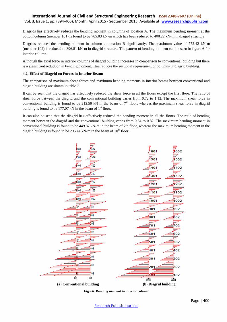
Diagrids has effectively reduces the bending moment in columns of location A. The maximum bending moment at the
bottom column (member 101) is found to be 765.83 kN-m which has been reduced to 408.22 kN-m in diagrid structure.
Diagrids reduces the bending moment in column at location B significantly. The maximum value of 772.42 kN-m
(member 102) is reduced to 396.81 kN-m in diagrid structure. The pattern of bending moment can be seen in figure 6 for
interior column.
Although the axial force in interior columns of diagrid building increases in comparison to conventional building but there
is a significant reduction in bending moment. This reduces the sectional requirement of columns in diagrid building.
4.2. Effect of Diagrid on Forces in Interior Beam:
The comparison of maximum shear forces and maximum bending moments in interior beams between conventional and
diagrid building are shown in table 7.
It can be seen that the diagrid has effectively reduced the shear force in all the floors except the first floor. The ratio of
shear force between the diagrid and the conventional building varies from 0.72 to 1.12. The maximum shear force in
conventional building is found to be 212.59 kN in the beam of 7th
floor, whereas the maximum shear force in diagrid
building is found to be 177.07 kN in the beam of 1st floor.
It can also be seen that the diagrid has effectively reduced the bending moment in all the floors. The ratio of bending
moment between the diagrid and the conventional building varies from 0.54 to 0.82. The maximum bending moment in
conventional building is found to be 449.87 kN-m in the beam of 7th floor, whereas the maximum bending moment in the
diagrid building is found to be 295.44 kN-m in the beam of 10th
floor.
(a) Conventional building (b) Diagrid building
Fig – 6: Bending moment in interior column

International Journal of Civil and Structural Engineering Research ISSN 2348-7607 (Online) Vol. 3, Issue 1, pp: (394-406), Month: April 2015 - September 2015, Available at: www.researchpublish.com
Page | 401 Research Publish Journals
Table - 3: Comparison of Axial force in Interior Column between Conventional and Diagrid building at location A
Mem
ber
Load Case no 7{1.5[DL+LL]} Load Case no 8
{1.2[DL+LL+EQ(X)]}
Load Case no 12
{1.5[DL+EQ(X)]
Load Case no 16
{0.9DL+1.5EQ(X)}
Conventi
onal Diagrid
Ratio
(Dia/
Con)
Conventi
onal Diagrid
Ratio
(Dia/Co
n)
Conventi
onal Diagrid
Ratio
(Dia/
Con)
Conventi
onal Diagrid
Ratio
(Dia/C
on)
101 7374.05 9617.89 1.30 5817.97 7335.12 1.26 4353.17 5570.71 1.28 2571.27 3162.83 1.23
201 6851.15 8963.46 1.31 5400.02 6826.51 1.26 4042.49 5182.41 1.28 2385.05 2937.32 1.23
301 6337.71 8303.76 1.31 4990.43 6321.67 1.27 3737.56 4799.95 1.28 2202.66 2719.30 1.23
401 5833.40 7649.94 1.31 4589.30 5825.15 1.27 3438.72 4425.52 1.29 2024.53 2507.91 1.24
501 5336.73 7076.68 1.33 4195.11 5371.92 1.28 3144.74 4067.81 1.29 1849.70 2295.97 1.24
601 4847.60 6432.67 1.33 3807.63 4888.74 1.28 2855.43 3707.46 1.30 1678.03 2095.78 1.25
701 4365.82 5783.70 1.32 3427.08 4404.35 1.29 2571.18 3346.72 1.30 1509.92 1896.73 1.26
801 3890.31 5141.77 1.32 3052.43 3925.98 1.29 2291.25 2990.83 1.31 1344.84 1700.78 1.26
901 3418.40 4589.56 1.34 2680.41 3489.21 1.30 2012.82 2644.19 1.31 1180.54 1495.29 1.27
1001 2950.13 3959.85 1.34 2310.70 3025.41 1.31 1735.46 2303.82 1.33 1016.57 1311.06 1.29
1101 2488.06 3324.95 1.34 1946.91 2557.70 1.31 1462.51 1959.96 1.34 855.74 1124.85 1.31
1201 2031.19 2697.03 1.33 1588.05 2090.91 1.32 1193.26 1614.49 1.35 697.51 935.33 1.34
1301 1575.42 2151.10 1.37 1229.82 1663.61 1.35 924.24 1278.62 1.38 539.29 738.53 1.37
1401 1119.04 1529.25 1.37 871.02 1190.95 1.37 654.78 924.14 1.41 380.77 538.26 1.41
1501 665.59 902.36 1.36 515.70 709.09 1.38 388.30 559.75 1.44 224.60 329.46 1.47
1601 211.92 282.25 1.33 161.45 224.88 1.39 123.23 189.90 1.54 69.90 113.48 1.62
Note: Ratio Dia/Con indicates ratio of member forces between Diagrid and Conventional building
Table - 4: Comparison of Axial force in Interior Column between Conventional and Diagrid building at location B
Mem
ber
Load Case no 7
{1.5[DL+LL]}
Load Case no 8
{1.2[DL+LL+EQ(X)]}
Load Case no 12
{1.5[DL+EQ(X)]
Load Case no 16
{0.9DL+1.5EQ(X)}
Conventio
nal Diagrid
Rati
o
(Dia/
Con)
Conventi
onal Diagrid
Rati
o
(Dia/
Con)
Conventio
nal Diagrid
Rati
o
(Dia/
Con)
Conventi
onal Diagrid
Rati
o
(Dia
/Con
)
102 7374.05 9617.89 1.30 5984.85 8053.50 1.35 4561.76 6468.69 1.42 2777.69 4060.81 1.46
202 6851.15 8963.46 1.31 5566.20 7515.03 1.35 4250.22 6043.06 1.42 2590.58 3797.97 1.47
302 6337.71 8303.76 1.31 5154.38 6964.35 1.35 3942.49 5603.30 1.42 2405.36 3522.65 1.46
402 5833.40 7649.94 1.31 4743.25 6414.75 1.35 3631.16 5162.51 1.42 2217.41 3244.91 1.46
502 5336.73 7076.68 1.33 4342.90 5950.76 1.37 3329.48 4791.36 1.44 2034.83 3019.53 1.48
602 4847.60 6432.67 1.33 3947.88 5403.53 1.37 3030.74 4350.94 1.44 1853.67 2739.26 1.48
702 4365.82 5783.70 1.32 3557.67 4849.57 1.36 2734.43 3903.25 1.43 1673.45 2453.25 1.47
802 3890.31 5141.77 1.32 3171.58 4300.84 1.36 2440.20 3459.40 1.42 1494.03 2169.35 1.45
902 3418.40 4589.56 1.34 2788.63 3854.09 1.38 2148.10 3100.29 1.44 1316.02 1951.39 1.48
1002 2950.13 3959.85 1.34 2409.17 3310.35 1.37 1858.55 2660.01 1.43 1139.83 1667.24 1.46
1102 2488.06 3324.95 1.34 2033.72 2762.21 1.36 1571.02 2215.59 1.41 964.38 1380.48 1.43
1202 2031.19 2697.03 1.33 1661.63 2224.34 1.34 1285.23 1781.29 1.39 789.59 1102.13 1.40
1302 1575.42 2151.10 1.37 1290.68 1778.16 1.38 1000.32 1421.81 1.42 615.45 881.72 1.43
1402 1119.04 1529.25 1.37 919.31 1255.85 1.37 715.15 1005.27 1.41 441.19 619.39 1.40
1502 665.59 902.36 1.36 549.16 734.68 1.34 430.12 591.74 1.38 266.45 361.44 1.36
1602 211.92 282.25 1.33 177.58 226.72 1.28 143.39 192.19 1.34 90.08 115.77 1.29
Note: Ratio Dia/Con indicates ratio of member forces between Diagrid and Conventional building

International Journal of Civil and Structural Engineering Research ISSN 2348-7607 (Online) Vol. 3, Issue 1, pp: (394-406), Month: April 2015 - September 2015, Available at: www.researchpublish.com
Page | 402 Research Publish Journals
Table - 5: Comparison of Bending moment in Interior Column between Conventional and Diagrid building at location A
Memb
er
Load Case no 7{1.5[DL+LL]} Load Case no
8{1.2[DL+LL+EQ(X)]}
Load Case no 12
{1.5[DL+EQ(X)]
Load Case no 16
{0.9DL+1.5EQ(X)}
Conventi
onal
Diagri
d
Ratio(
Dia/con
)
Conven
tional Diagrid
Ratio(
Dia/con
)
Conventi
onal
Diagri
d
Ratio(
Dia/con
)
Conven
tional Diagrid
Ratio(
Dia/co
n)
101 -9.44 33.12 -3.51 608.63 330.08 0.54 764.19 408.22 0.53 765.83 405.37 0.53
201 -13.32 43.47 -3.26 433.36 247.05 0.57 544.38 295.68 0.54 545.48 287.54 0.53
301 -20.52 38.36 -1.87 344.38 191.89 0.56 438.08 226.41 0.52 441.47 216.45 0.49
401 -27.46 33.83 -1.23 295.23 149.82 0.51 379.75 175.32 0.46 384.55 166.57 0.43
501 -32.66 23.73 -0.73 259.44 137.03 0.53 337.38 174.99 0.52 343.35 173.69 0.51
601 -37.75 33.45 -0.89 242.81 152.62 0.63 319.69 183.09 0.57 326.99 175.87 0.54
701 -44.32 30.12 -0.68 232.46 142.80 0.61 311.33 170.47 0.55 320.75 161.64 0.50
801 -51.82 -23.33 0.45 231.92 127.46 0.55 314.25 154.57 0.49 325.24 148.12 0.46
901 -48.69 -15.63 0.32 208.97 139.36 0.67 284.01 185.62 0.65 294.37 187.30 0.64
1001 -52.17 21.03 -0.40 194.56 149.91 0.77 267.67 184.30 0.69 278.75 178.45 0.64
1101 -57.21 19.19 -0.34 174.21 147.82 0.85 244.54 183.26 0.75 256.71 177.66 0.69
1201 -63.83 -29.04 0.45 152.11 102.72 0.68 220.07 148.74 0.68 233.63 152.23 0.65
1301 -56.82 -18.25 0.32 118.67 81.84 0.69 174.95 107.38 0.61 187.04 105.43 0.56
1401 -58.41 11.46 -0.20 85.40 90.29 1.06 134.15 113.72 0.85 146.56 108.79 0.74
1501 -60.93 10.89 -0.18 44.17 62.42 1.41 83.63 79.19 0.95 96.63 75.23 0.78
1601 -82.31 -41.37 0.50 -17.29 -6.57 0.38 17.31 17.20 0.99 34.67 24.88 0.72
Note: Ratio Dia/Con indicates ratio of member forces between Diagrid and Conventional building
Table 6: Comparison of Bending moment in Interior Column between Conventional and Diagrid building at location B
Mem
ber
Load Case no 7{1.5[DL+LL]} Load Case no
8{1.2[DL+LL+EQ(X)]}
Load Case no 12
{1.5[DL+EQ(X)]
Load Case no 16
{0.9DL+1.5EQ(X)}
Conventi
onal Diagrid
Ratio(
Dia/co
n)
Conventi
onal
Diagri
d
Ratio(Di
a/con)
Conventi
onal Diagrid
Ratio
(Dia/c
on)
Conven
tional Diagrid
Ratio
(Dia/
con)
102 9.44 -33.12 -3.48 620.65 311.67 0.50 772.42 393.96 0.51 770.78 396.81 0.51
202 13.32 -43.47 -3.27 441.93 193.49 0.44 549.74 254.99 0.46 548.70 263.13 0.48
302 20.52 -38.36 -2.21 369.97 130.52 0.35 454.85 176.60 0.39 451.54 186.56 0.41
402 27.46 -33.83 -1.24 329.12 95.70 0.29 400.69 131.58 0.33 397.12 140.33 0.35
502 32.66 -23.73 -0.73 304.22 137.76 0.45 367.21 168.50 0.46 361.24 169.80 0.47
602 37.75 -33.45 -0.89 297.94 111.45 0.37 356.24 147.00 0.41 348.92 154.22 0.44
702 44.32 -30.12 -0.68 303.33 94.61 0.31 358.42 126.30 0.35 349.01 135.13 0.39
802 51.82 23.33 0.45 314.79 129.76 0.41 369.13 145.31 0.39 358.17 142.73 0.40
902 48.69 15.63 0.32 286.84 164.36 0.57 335.74 194.02 0.58 325.40 192.34 0.59
1002 52.17 -21.03 -0.40 278.00 121.56 0.44 323.04 155.04 0.48 311.97 160.89 0.52
1102 57.21 -19.19 -0.34 265.71 94.32 0.35 305.36 155.27 0.51 293.20 160.87 0.55
1202 63.83 29.04 0.46 254.21 149.19 0.59 287.82 166.15 0.58 274.28 162.67 0.59
1302 56.82 18.25 0.32 209.56 87.51 0.42 235.33 97.64 0.41 223.26 99.59 0.45
1402 58.41 -11.46 -0.20 178.84 71.96 0.40 196.15 89.10 0.45 183.76 94.02 0.51
1502 60.93 -10.89 -0.18 141.64 48.43 0.34 148.64 59.36 0.40 135.64 63.33 0.47
1602 82.31 41.37 0.50 114.38 59.63 0.52 104.04 46.96 0.45 86.70 41.44 0.48
Note: Ratio Dia/Con indicates ratio of member forces between Diagrid and Conventional building

International Journal of Civil and Structural Engineering Research ISSN 2348-7607 (Online) Vol. 3, Issue 1, pp: (394-406), Month: April 2015 - September 2015, Available at: www.researchpublish.com
Page | 403 Research Publish Journals
4.3. Effect of Diagrid on Forces in Perimeter Beam:
The comparison of maximum shear forces and maximum bending moments in perimeter beams between conventional and
diagrid building are discussed as per table 8.
It can be seen that the shear force has been reduced significantly in the diagrid building. The ratio between the diagrid and
the conventional building varies from 0.54 to 0.95. The maximum value of shear force in the conventional building is
found to be 164.40 kN in the beam of 7th
floor, where as the maximum value of shear force in the diagrid building is
found to be 143.46 kN in the beam of 10th
floor.
It can also be seen that the bending moment has been reduced significantly and effectively. The ratio between the diagrid
and the conventional building varies from -0.23 to -0.54. The negative sign indicate the reversal of bending moment value
in the diagrid building. The maximum value of bending moment in the conventional building is found to be -372.30 kN-m
in the beam of 7th
floor, where as the maximum bending moment in the diagrid building is found to be 151.17 kN-m in the
beam of 10th
floor.
The shear force and bending moment pattern of interior and perimeter beams can be seen in figure 7 and figure 8
respectively.
(a) Conventional building (b) Diagrid building
Figure 7: Shear force diagram of selected floor beams for conventional and diagrid building
Table - 7: Comparison of maximum shear force and maximum bending moment in Interior Beams between the
Conventional and Diagrid building
Internal
beams at
Maximum Shear Force Maximum Bending Moment
Conventional Diagrid Ratio (Dia/con) Conventional Diagrid Ratio (Dia/con)
16th
Floor 98.20 83.90 0.85 -166.88 -97.46 0.58
13th
Floor 178.50 167.49 0.94 -342.63 -227.68 0.66
10th
Floor 203.64 172.98 0.85 -419.97 -295.44 0.70
7th
Floor 212.59 173.24 0.81 -449.87 -269.97 0.60
4th
Floor 205.51 147.55 0.72 -438.52 -238.88 0.54
1st
Floor 157.92 177.07 1.12 -280.52 -230.53 0.82
Table - 8: Comparison of shear force and bending moment in Perimeter Beams between the Conventional and Diagrid
building
Perimeter
beams at
Maximum Shear Force Maximum Bending Moment
Conventional Diagrid Ratio (Dia/con) Conventional Diagrid Ratio (Dia/con)
16th
Floor 62.21 54.49 0.88 -115.66 62.77 -0.54
13th
Floor 128.60 92.67 0.72 -250.30 63.85 -0.26
10th
Floor 150.49 143.46 0.95 -331.67 157.17 -0.47
7th
Floor 164.40 87.98 0.54 -372.30 84.13 -0.23
4th
Floor 162.79 92.75 0.57 -367.17 106.49 -0.29
1stFloor 116.72 88.43 0.76 -213.81 78.13 -0.37

International Journal of Civil and Structural Engineering Research ISSN 2348-7607 (Online) Vol. 3, Issue 1, pp: (394-406), Month: April 2015 - September 2015, Available at: www.researchpublish.com
Page | 404 Research Publish Journals
(a) Conventional building (b) Diagrid building
Fig - 8: Bending moment diagram of selected floor beams for conventional and diagrid building
The diagrid configuration provide a reduction in the span of peripheral beams at alternate floors, however this span
remains constant in conventional building. Hence a significant reduction in forces of peripheral beams is found at
alternate floors.
4.4. Effect of Diagrid on Weight of the Building:
The comparison of weight of columns and weight of beams between conventional and diagrid building is shown in table 9
and table 10 respectively. In the diagrid building the sectional requirement of the members has been reduced when
compared to the conventional building. A reduction of nearly 6% in column weight and 17% in beam weight is found in
diagrid building compared to conventional building. An overall advantage of approximately 12% in weight is seen in the
diagrid building.
Table 9: Comparison of Weight of Columns between Conventional and Diagrid building
Type of Structural Member Conventional Building Diagrid Building
Section Weight (kN) Section Weight (kN)
Columns 1st-
4th Floor
Vertical Steel tube 850x850x20 mm 979.36 Steel tube 850x850x20 mm 244.84
Diagonal - - Steel Tube 650x650x10 mm 633.23
Columns 5th-
8th Floor
Vertical Steel tube 750x750x20 mm 861.36 Steel tube 675x675x20 mm 193.22
Diagonal - - Steel Tube 650x650x10 mm 633.23
Columns 9th-
12th Floor
Vertical Steel tube 650x650x15 mm 561.95 Steel tube 575x575x15 mm 123.90
Diagonal - - Steel Tube 400x400x10 mm 385.88
Columns 13th-
16th Floor
Vertical Steel tube 550x550x15 mm 473.45 Steel tube 475x475x15 mm 101.77
Diagonal - - Steel Tube 400x400x10 mm 385.88
Total Weight (kN) 2876.12
2701.95
Table 10: Comparison of Weight of Beams between Conventional and Diagrid building
Type of Structural Member Conventional Diagrid
Section Weight (kN) Section Weight (kN)
Internal Beams ISWB550 with Cover
Plate of 250x10 mm TB 1710.63
ISWB500 with Cover
Plate of 250x10 mm TB 1515.05
Perimeter Beams 1 { Floors: 1, 3, 5, 7,
9, 11, 13, 15} ISWB600 753.99 ISWB550 634.07
Perimeter Beams 2 { Floors: 2, 4, 6, 8,
10, 12, 14, 16} ISWB600 753.99 ISWB500 536.29
Total Weight (kN) 3218.61
2685.41

International Journal of Civil and Structural Engineering Research ISSN 2348-7607 (Online) Vol. 3, Issue 1, pp: (394-406), Month: April 2015 - September 2015, Available at: www.researchpublish.com
Page | 405 Research Publish Journals
5. CONCLUSION
In the present study G+15 storey conventional and diagrid building is analysed under gravity and seismic loading. The
results are compared to evaluate the utility of diagrids. The following conclusions are made on the basis of present work:
A significant decrease of bending moment in interior columns of diagrid building is found in comparison to
conventional building.
The use of diagrids significantly decreases the maximum shear force and maximum bending moment in internal and
perimeter beams. The sign of maximum bending moment also changes in perimeter beams of diagrid building.
The diagrid configuration provides a reduction in the span of perimeter beams at alternate floors, hence reducing the
beam forces at alternate floors.
The sectional requirement of the members has been reduced in diagrid building when compared to the conventional
building. This results in an advantage of approximately 12% in weight for diagrid building.
REFERENCES
[1] ALI, M.M. and MOON, K.S. (2007), Structural Developments in Tall Buildings: Current Trends and Future
Prospects, Architectural Science Review, Vol. 50 No. 3, pp. 205‐223.
[2] BOAKE, T.M. (2013), Diagrids, the New Stability System: Combining Architecture with Engineering. School of
Architecture, University of Waterloo, Canada.
[3] BOAKE, T.M. (2013), Diagrid Structures: Innovation and Detailing. School of Architecture, University of Waterloo,
Canada.
[4] BOAKE, T.M. (2014), Diagrid Structures-system, Connection, Details, Berlin: World Steel Association, pp. 1-177
[5] GENDUSO, B. (2004), Structural redesign of a perimeter diagrid lateral system, Senior thesis, Architectural
Engineering, Penn State University, Pennsylvania, United State.
[6] GHOBARAH, A. (2000), Selective Column Rehabilitation of RC Frame, 12WCEE
[7] GOODSIR, W.J. (1985), The Design of Coupled Frame-Wall Structures for Seismic Actions, Ph.D. Thesis,
University of Canterbury, New Zealand.
[8] IS 1893(Part‐I): 2002. Criteria for Earthquake Resistant Design of Structures, Bureau of Indian Standard, New
Delhi.
[9] IS 800: 2007 General Constructions in Steel‐ Code of Practice, Bureau of Indian Standard, New Delhi.
[10] IS 875 (Part 1): 1987, Code of Practice for Design Loads (Other than Earthquake) for Buildings and Structure,
Bureau of Indian Standard, New Delhi.
[11] IS 875 (Part 2): 1987, Code of Practice for Design Loads (Other than Earthquake) for Buildings and Structure,
Bureau of Indian Standard, New Delhi.
[12] JANI, K. (2012), Analysis and Design of Diagrid Structural System for High Rise Steel Buildings. M.Tech.
Dissertation, Nirma University, Ahmedabad.
[13] JAIN, A. and GOEL, S. (1979), Seismic response of eccentric and concentric braced steel frames with different
proportions, UMEE 79R1, Department of Civil Engineering, University of Michigan, Ann Arbor, pp. 1-88.
[14] MCCAIN, I. (2008), DiaGrid: Structural Efficiency & Increasing popularity, London.
[15] KAREEM, K., KIJEWSKI, T. and TAMURA, Y. (1999), “Mitigation of Motions of Tall Buildings with Specific
Examples of Recent Applications”, Wind and Structures, Vol. 2, No. 3, pp. 201‐251.
[16] KIM, J., JUN, Y. and LEE, Y.H. (2010), Seismic Performance Evaluation of Diagrid System Buildings. 2nd
Specialty Conference on Disaster Mitigation, Manitoba.

International Journal of Civil and Structural Engineering Research ISSN 2348-7607 (Online) Vol. 3, Issue 1, pp: (394-406), Month: April 2015 - September 2015, Available at: www.researchpublish.com
Page | 406 Research Publish Journals
[17] KHATIB, I. and MAHIM, S. (1987), Dynamic inelastic behavior of chevron braced steel frame, 5th
Canadian
Conference on Earthquake Engineering, Balkema, Rotterdam, pp. 211-220.
[18] KORSAVI, S. and MAQHAREH, M.R. (2014), the Evolutionary Process of Diagrid Structure towards
Architectural, Structural and Sustainability Concepts: Reviewing Case Studies. J Architectural Engineering
Technology Vol. 3, pp. 1-11.
[19] KUMAR, R. (2014), Seismic analysis of braced steel frame, B. Tech. Project, NIT, Rourkela.
[20] LEONARD, J. (2007), Investigation of Shear Lag Effect in High-Rise Buildings with Diagrid System, M.S. thesis,
Massachusetts Institute of Technology.
[21] MOON, K.S. (2005), Dynamic Interrelationship between Technology and Architecture in Tall Buildings, Ph.D.
dissertation, Department of Architecture, Massachusetts Institute of Technology, 2005.
[22] MOON, K.S. (2008), Optimal Grid Geometry of Diagrid Structures for Tall Buildings. Architectural Science
Review, 51.3, pp. 239‐251.