Advances in Sulfuric Acid Plant Equipment and · PDF file98.2.6 Advances in Sulfuric Acid...
13
98.2.6 Advances in Sulfuric Acid Plant Equipment and Processes Monsanto Enviro-Chem Systems P.O. Box 14547 St. Louis, Mo 63178 Authors S.M. Purcelli J.C. Burk T.J. Schnepf N. Bhambri S.A. Ziebold Sulfuric acid production, being one of the oldest chemical processes in the world, has seen remarkable technology improvements over the course of its history. Sulfuric acid plants have progressed from a low efficiency, smokestack industry, to a highly efficient, environmentally responsible industry.
Transcript of Advances in Sulfuric Acid Plant Equipment and · PDF file98.2.6 Advances in Sulfuric Acid...

98.2.6
Advances
in
Sulfuric Acid Plant
Equipment and Processes
Monsanto Enviro-Chem SystemsP.O. Box 14547
St. Louis, Mo 63178
AuthorsS.M. PurcelliJ.C. BurkT.J. SchnepfN. BhambriS.A. Ziebold
Sulfuric acid production, being one of the oldest chemical processes in theworld, has seen remarkable technology improvements over the course of itshistory. Sulfuric acid plants have progressed from a low efficiency, smokestackindustry, to a highly efficient, environmentally responsible industry.

2
From its birth into commercial production, using the chamber process, sulfuric acidquickly moved into adolescence, with the adoption of the markedly improved contactprocess. In the early 1970’s, sulfuric acid became of age, with the introduction ofenvironmentally friendly and energy efficient double catalysis process. And in the lastdecade, sulfuric acid technology has moved into its prime, becoming more refined andproving the adage that the industry is not getting older, but is getting better.
In recent times, environmental regulations and market forces have shown a need forlower emissions, higher energy recovery and increased reliability. These needs havebeen addressed by technology suppliers with subtle refinements of equipment andproducts, not by broad changes to the process. Because of this, the improvements arenot outwardly apparent, even to the trained eye. This paper will be to call attention tothose somewhat “hidden” changes, which continue to improve the sulfuric acid industry.
Some of the more significant improvements evident in the industry are summarizedbelow and will be discussed in more detail in this paper:
• As environmental awareness has increased, catalyst technology has improved,leading to lower emissions.
• Mist eliminator capture efficiencies have improved, providing owners with options
for very low mist emission requirements. • Candle mist eliminators in dry towers can provide increased protection for
downstream equipment, without excessive fouling. • Analysis of tower hydraulics has lead to more efficient distributors, without
sacrificing absorption or paying significantly higher prices. • Acid cooler anodic protection systems have moved forward with digital controllers
and Graphic User Interface (GUI). • Plate gas/gas heat exchangers provide greater material and capacity flexibility for
sulfuric acid plants.
ADVANCES IN SO2 ABATEMENT TECHNOLOGY: Over the last several years, the reduction of SO2 emissions from sulfuric acid plantshas become an increasingly important topic, both from a legislative and environmentalconsciousness viewpoint. It has been demonstrated in numerous cases that an SO2
emission level of 100 ppm can be achieved using low feed gas strengths, large catalystvolumes, and four or more catalyst beds. Recently developments in low ignition temperature, cesium promoted sulfuric acidcatalysts, have revolutionized the concept of reducing SO2 emissions in a cost andenergy effective manner. Using cesium-promoted catalysts (Cs-120 and Cs-110),Monsanto Enviro-Chem has demonstrated significant emissions reductions, comparedto standard potassium promoted vanadium-based catalysts. The following exampleswill demonstrate this cost effective application of catalyst technology for enhancedproduction and reduced emissions within the sulfuric acid industry. CASE # 1:

3
A sulfur burning customer wished to increase their production while maintain their totalSO2 emissions limit. The plant is single absorption with air dilution to beds # 3 and # 4and a feed gas composition of 9.50 % SO2 and 11.45 % O2. The converter containedconventional catalyst in beds # 1, # 2, and # 3 with cesium-promoted Cs-110 ringcatalyst added to bed # 4. The use of the cesium promoted catalyst allowed pass #4 to be operated at 770°F(410°C ), which resulted in a more favorable equilibrium conversion level and loweremissions. The result was an 18 % increase in production, with no increase in dailyso2 emissions. This can be compared to standard catalyst, which would have resultedin emissions which were 13 % higher than the allowed limit.
CASE # 2: A metallurgical customer, needing to control smelter-wide sulfur emissions, found itnecessary to minimize sulfuric acid plant emissions. The plant is a conventional doubleabsorption plant with HRS. The design feed gas composition is 14.0 % SO2 and 14.0% O2. The converter contained conventional catalyst in beds # 2, and # 3 with a 50%cap of cesium-promoted Cs-120 in pass #1 and Cs-110 ring catalyst in bed # 4. The cesium promoted catalyst in pass #1 was used to control the highly exothermicreaction in the first pass. By operating the first pass inlet at 734°F (390°C) the outlettemperature could be controlled to 1,175°F (635°C). The use of cesium promotedcatalyst in pass #4 allowed it to be operated at 734°F (390°C ), which resulted in amore favorable equilibrium limits and lower emissions. The overall result was a stackemission < 75 ppm. This can be compared to standard catalyst, which would have hada theoretical limit of 110 ppm, with considerably higher catalyst loading.
CASE # 3: A sulfur burning customer was regulated by governing authorities to a maximum of 100ppm, adjusted to an 8% O2 basis. To do so, required the sulfuric acid plant emissionsto be 99.9%. The plant was a 3 X 2 interpass plant with dilution cooling betweenpasses 4 and 5. The a feed gas composition is 11.50 % SO2 and 9.45 % O2. Theconverter contained conventional LP-120/LP-110 catalyst in beds # 1, # 2, # 3 and #4,with cesium-promoted Cs-110 ring catalyst added to bed # 5. The use of the cesium promoted catalyst allowed pass #5 to be operated at 734°F(390°C), which resulted in a more favorable equilibrium and lower emissions. Theresult was a stack emission level < 100 ppm. There are also many examples in which the cesium-promoted catalyst has been usedto circumvent a plant-related problem which was causing high SO2 emissions: fouledheat exchangers leading to low bed inlet temperatures, high start-up emissions,difficulties in heating certain catalyst beds during plant startup, etc. Furthermore, thecesium-promoted catalyst can be utilized to redirect heat from one heat-extracting unitto another in order to optimize steam production. All of these applications are uniquelydesigned for each client. Use of this catalyst may not be economically appropriate forall sulfuric acid producers. Each situation must be studied to determine the applicabilityof cesium catalyst.
Reducing Acid Mist Emissions:

4
An equally important emission issue centers around sulfuric acid mist. And, controltechnology has progressed here, equally as well. Acid mist emissions can be reducedbelow the EPA limit of 0.15 lbs/ST and is being more frequently required by sulfuricacid clients to suite local regulations and permitting. There are many design parameters to consider when low level acid stack emissions arerequired. Acid mist formation in absorbing towers is very complicated. Resultant mistparticle size distribution is typically bi-modal since submicron particles are formed byreaction/condensation while larger particles are formed by mechanical means. Mist eliminator design is based on the amount of mist that is generated, mist particlesize distribution and maximum allowable emissions. Effective performance can beachieved by proper selection of mist eliminator type, style (orientation), and designvelocities, along with careful installation and maintenance. For low exit mist emissions, the bi-component ES mist eliminator as shown in Figure 1or the HE “Plus” are good choices since they have high collection efficiency on smallparticles which improves with plant turndown. The inclusion of a drainage layersignificantly reduces acid mist re-entrainment.
Figure 1: ES and HE-Plus elements
A good example of the capability of these mist eliminator elements is the recent startupof a sulfur burning IPA sulfuric acid plant, with a design rate of 700 STPD. The stackacid emission requirement was < 0.075 pounds mist per short ton of acid produced asmeasured by Method 8. This is half the EPA standard acid mist limit. Utilizing 16 ES elements in the final absorbing tower, the actual measured acid mistemission was less than 0.012 pounds mist per short ton of acid produced at designplant rate. This is equivalent to a mist loading of about 0.08 mg/ACF. Thus for thisnew Monsanto sulfuric acid plant, maximum measured acid emission at start-up wasabout eight percent of the standard EPA limit.
Impaction Candles for Dry Towers

5
Because fiber bed impaction devices have higher removal efficiency on smallerparticles, compared to mesh pads, they provide more protection for downstreamequipment such as a compressor wheel, first pass catalyst, expansion joints andductwork. The candle arrangement has horizontal gas flow, which improves liquiddrainage, since collected acid mist is not held up in the media by the gas. Candleelements also operate at lower velocity compared to mesh pads and are more tolerableto volumetric flow variation. In addition to improved performance, consideration should also be given to the cost ofthe operation. Candle elements in dry tower service are usually repacked after severalyears due to the corrosion of the wire mesh re-entrainment control layer and loss ofinterwoven glass fibers. In some cases, portions of the drainage layer can be reused.Removing and installing candle elements is safer and quicker than mesh pads, thussaving plant downtime.
Figure 2: CS-1P and CK-1P Field Performance
The standard in this service has been the CS-IP impaction fiber bed. It is designed forimproved dry tower performance in sulfuric acid plants. The bed is a cylindrical bi-component packing design using a fiber glass mat for collecting small particles plus analloy mesh re-entrainment control or “drainage” layer. In sulfur burning drying towerservice, CS elements usually need to be washed every 6 to 18 months depending ontower design, and the level and nature of plugging agents. A new impaction fiber bed for dry towers, the CK, is now available to operate longerbetween washings and extend time between maintenance shut downs. For sulfurburning plants, service life is typically two years or longer. Although CK elements look

6
the same as CS elements from the outside, the internal Co-knit collection layer issignificantly different than standard CS collecting glass media. CK beds are identical insize and capacity to standard CS beds operating at the same gas volume and cleanpressure drop. Like the CS design, CK elements also include an alloy mesh re-entrainment control layer. CK elements use a metal mesh for the collecting layer but this metal mesh structure hassmall diameter acid resistant glass fibers knitted together into the metal wires toincrease the collection targets and thus small particle collection efficiency. The Co-knitmetal mesh collecting layer is considerably thicker and has a higher void fraction thanthe glass collecting layer used in standard CS elements. Because of this openstructure, in severe plugging situations, CK elements operate much longer betweencleanings than regular CS elements. Figure 2 illustrates actual field performance of standard CS-IP elements compared tonew CK-IP elements in severe plugging installations where towers were highly sulfatedand no upstream air filters were used. The new CK elements ran significantly longer indry tower service before needing to be washed or repacked. CS or CK beds can be washed outside the tower very easily by dunking in a sump orusing low pressure hose water flushing. Washing this way normally restores beds totheir original pressure drop.
Alloy Distributors at Cast Iron Prices
Figure 3: Types of Sulfuric Acid Distributors
Acid distribution systems are thekey component to good SO3
absorption in sulfuric acid plants.Over the years, acid distributorshave evolved into designs usingalloy materials and better acidcoverage across a tower crosssection. Since there are manyapproaches to any givenproblem, one must be careful inchoosing an acid distributor thatis best suited for the givensituation. Acid distributors are designed touniformly distribute acid over abed of packing. A gas streamflowing counter-currently to thisacid flow is contacted by the acidto absorb SO3. Good SO3
absorption is crucial to tower performance and is a function of
the uniformity of the acid distribution. Non-uniform distribution can cause problemssuch as mist generation and SO3 slippage. This can result in exceeding emissionstandards and excessive corrosion in downstream equipment. As shown above, thereare three main styles of acid distributors used in the sulfuric acid industry today.

7
New Generation Alloy Trough Distributors
Taking trough style distributordesign one step further, the NewGeneration Alloy TroughDistributor (patent pending) byMonsanto Enviro-Chem Systemsis the state-of-the-art distributor onthe market today. This distributormaintains the alloy trough anddowncomer design, but eliminatesthe required overhead pipesystem. Instead the troughsections are connected togetherby a series of ducts. A set of gatevalves in each trough thenregulates the flow to eachsegment of the trough.
The New Generation distributor can accommodate varying flow rates by just raising orlowering the adjustable gates in each trough. This makes the system easy to retrofit forhigher capacity. A computer program models each individual system to calculate thecorrect gate heights required to ensure uniform distribution. Wider and deeper troughs result in very low acidvelocities inside thetroughs. These lowvelocities translate intovery smooth acid flowand equal distribution toall areas of the tower.Optional flow straight-eners downstream ofthe adjustable gatescan make trough acidvelocities even lower.Concerns that solids,such as packing chips,will stay suspended inalloy style troughscausing pluggage of thedowncomers are furtherreduced with the larger,less turbulent, pool of
.
acid. Without the need for header piping in a trough there is now more room fordowncomers in a single troughThis reduces the number of troughs required to correctlycover a tower diameter. Systems where 6 and 7 troughs were needed before now,require only 4 or 5 troughs. This keeps gas velocities low and mist generation to aminimum.

8
New Generation distributors can be made from a choice of alloy materials which suit acustomers specific design needs. Lighter materials and fewer troughs has made thissystem even easier to install. This distributor also requires very little maintenance. Other benefits of alloy trough distributors are: • Complete coverage of the perimeter of the tower. Downcomers can be designed to
cover all portions of the tower, even the perimeter. This means no channeling ofgas through the packing as seen with the pipe, cast iron and hybrid distributors.
• More coverage means less packing is required. ( Increasing the distribution pts/ft²
to 4 can reduce packing height to 8 ft.). This in turn reduces pressure drop acrossthe tower and can increase capacity, in some cases.
• The design occupies a much smaller cross sectional area of the tower thus
reducing gas velocity. Lower velocity results in less mist generation. • Can be used in new and retrofit applications.
By removing header piping from the design, New Generation style distributors are morecost efficient. A couple of cost comparisons are shown below for towers approximately20 feet in diameter.
Comparison1
Comparison2
Acid Concentration 98.6% 96%Acid Distribution Points 1.4 pts./ft2 2 pts./ft2
Base Cast Iron Acid Distribution System $260/ft2
310M New Generation Distribution System $275/ft2
Hybrid Distributor System (Estimated) $450/ft2
SX New Generation Distribution System $450/ft2
As it can be seen, the New Generation Trough Style Distributor in 310M is very costcompetitive with basic cast iron distributors. Interestingly, premium materials, such asSX, can even be purchased for the same price as a hybrid style distributor.

9
Figure 4: New Generation Distributor for a 21.75 ft. ID Tower
Digital Anodic Protections Systems with GUI
In a continuing effort to improve our products, Monsanto Enviro-Chem has introduced anew generation of Anodic Protection - Filmgard 4 for acid coolers. The unit Filmgard4 offers a touch screen graphical user interface (GUI) for the input and monitoring ofdata, an integrated control system using state of the art equipment, increased PowerPac output and the ability to remotely troubleshoot cooler problems.
The operator interface on the Filmgard 4 system features color graphics, which canconcurrently present all electrode readings and control parameters for a cooler. Themonitoring of values for cathodes and reference electrodes and the announcement andcontrol of alarms are all functions controlled directly through the GUI. Setpoint input isthrough an integrated electronic number pad.

10
The input of critical information, such as control or alarm setpoints, are passwordprotected to avoid any unauthorized tampering. Up to three individual coolers can becontrolled from one operator interface. This feature allows for a reduction in costs, andcentralization of control.
Another significant advantage to the new operator interface is that data received from acooler’s cathodes or reference electrodes will be trended and displayed for the previous48 hours. The resulting trending will give plant operators and engineers a valuable toolin troubleshooting plant operational problems, and reviewing operating history. Thefollowing illustration shows the format in which the trended data will be displayed:
The Filmgard 4 controller utilizes a proprietary integrated digital controller, whichreplaces the custom circuit boards. This controller contains a proprietary program,which graphically represents input and output signals and also controls the applicationof current from the Power Pac to the cooler cathodes. This controller is a lessexpensive, more reliable alternative to circuit boards, and has resulted in anapproximately 10% reduction in the controller cost for Filmgard 4.
Another advantage of the integrated controller is the ability to remotely troubleshootproblems. All Filmgard 4 controllers come equipped with an external phone jack.Through this, Monsanto will be able to monitor the cooler remotely and diagnose theproblem much quicker. This standard feature can reduce the necessity for field calls.
As with the last generation controller, certain pieces of the Power Pac have becomeoutdated. The SCR firing circuit and the Triac from the Filmgard 3 are no longer offthe shelf items, and must be custom manufactured. These items have been replacedwith a new, readily available firing circuit module for Filmgard 4. Also, the output ofthe Filmgard 4 Power Pac has been increased, to allow for most coolers to bepassivated with only one Power Pac. With Filmgard 3, if a cooler was larger than5000ft2, two Power Pacs were required for passivation. This benefit results in a lowerprice for customers with larger coolers, as it reduces the waste of multiple Power Pacs.
11
The Filmgard 4 system is compatible with most DCS systems. Should the client wishto incorporate the Filmgard 4 system into a new or existing DCS system, MEC canprovide the necessary equipment and logic diagrams to make this possible. This optionprovides a significant cost savings, as it eliminates the controller portion of the standalone system.
Plate Gas/Gas Heat Exchangers
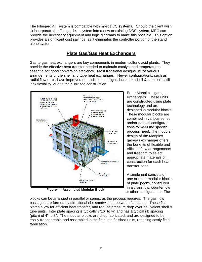
Gas to gas heat exchangers are key components in modern sulfuric acid plants. Theyprovide the effective heat transfer needed to maintain catalyst bed temperaturesessential for good conversion efficiency. Most traditional designs utilize variousarrangements of the shell and tube heat exchanger. Newer configurations, such asradial flow units, have improved on traditional designs, but these shell & tube units stilllack flexibility, due to their unitized construction.
Figure 4: Assembled Modular Block
Enter Monplex gas-gasexchangers. These unitsare constructed using platetechnology and aredesigned in modular blocks.These modular blocks arecombined in various seriesand/or parallel configura-tions to meet the specificprocess need. The modulardesign of the Monplexgas-gas exchanger offersthe benefits of flexible andefficient flow arrangementsand freedom to selectappropriate materials ofconstruction for each heattransfer zone.
A single unit consists ofone or more modular blocksof plate packs, configuredin a crossflow, counterflow
or other configuration. The
blocks can be arranged in parallel or series, as the process requires. The gas flowpassages are formed by directional ribs sandwiched between flat plates. These flatplates allow for efficient heat transfer, and reduce pressure drop over equivalent shell &tube units. Inter plate spacing is typically 7/16” to ¾” and has a typical rib spacing(pitch) of 4” to 8”. The modular blocks are shop fabricated, and are designed to beeasily transportable and assembled in the field into finished units, reducing costly fieldfabrication.

12
Monplex units have shown less than 0.5% leakage in shop testing. Onceoperational, the compressive forces of the rigid frame pack upon the expanded platearising fromthermal expansion reduce leakage to a level generally too low to measure. Obviously,fabrication using stainless steel, instead of traditional carbon steel, offers betterresistance to acid corrosion at the cold inlet of a shell & tube cold interpass heatexchanger and sulfidation in hot exchangers. The Monplex™ unit offers a uniqueopportunity for the heat exchanger designer to customize material selection for theservice, by specifying the appropriate metallurgy for each block. For example the coldblock with stainless steel plates, the intermediate block with carbon steel plates, andthe hot block with stainless steel plates, or whatever the specific process may require.Also, if pressure and flow requirements change due to modification in the existing plantprocess, the Monplex™ exchanger can easily be modified by adding additional units inparallel to meet the new process needs.
Modular Block Breakdown
This modular design with differentmaterials of construction also showsdistinct advantages when a unit is due forreplacement. A typical carbon steel shell& tube gas-gas exchanger will lastanywhere from 5-15 years, depending onspecific usage. Normally on a shell &tube exchanger, corrosion or excessivefouling is localized, and does not occurthroughout the entire exchanger.Obviously, shell & tube designs do noteasily allow for replacement of thedamaged area alone. The Monplex™design will allow for replacements ofindividual blocks, significantly reducingmaintenance costs.
The Monplex exchanger design also allows for easier cleaning than a standard shell& tube unit. The relatively small length of the block in the cross flow direction coupledwith the large width of the open unobstructed flow paths allows for inspection and waterwashing on both sides of the exchanger.
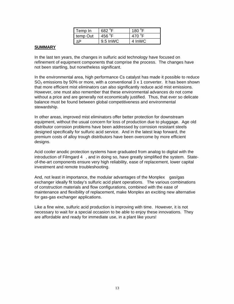
The first commercial installation of a Monplex Cold Interpass Exchanger started uplast fall in the USA. The Monplex unit was designed with three passes on the coldside, and one pass on the hot side. A 3 series x 3 parallel configuration was used, witheach unit with a crossflow configuration. The three cold pass blocks were constructedof 316 stainless steel, while the intermediate and hot passes were constructed ofcarbon steel. The exchanger was designed so that each pass could be removedindependently of the other two, either for maintenance or replacement. The exchangerhas been performing as expected. The design conditions of this unit are as follows:
Monplex reference unit design conditionsSO3 Gas SO2 gas
Flow Rate 440,511 lb/hr 334,377 lb/hr
13
Temp In 682 oF 180 oFtemp Out 456 oF 470 oF∆P 9.5 InWC 4 InWC
SUMMARY
In the last ten years, the changes in sulfuric acid technology have focused onrefinement of equipment components that comprise the process. The changes havenot been startling, but nonetheless significant.
In the environmental area, high performance Cs catalyst has made it possible to reduceSO2 emissions by 50% or more, with a conventional 3 x 1 converter. It has been shownthat more efficient mist eliminators can also significantly reduce acid mist emissions.However, one must also remember that these environmental advances do not comewithout a price and are generally not economically justified. Thus, that ever so delicatebalance must be found between global competitiveness and environmentalstewardship.
In other areas, improved mist eliminators offer better protection for downstreamequipment, without the usual concern for loss of production due to pluggage. Age olddistributor corrosion problems have been addressed by corrosion resistant steelsdesigned specifically for sulfuric acid service. And in the latest leap forward, thepremium costs of alloy trough distributors have been overcome by more efficientdesigns.
Acid cooler anodic protection systems have graduated from analog to digital with theintroduction of Filmgard 4, and in doing so, have greatly simplified the system. State-of-the-art components ensure very high reliability, ease of replacement, lower capitalinvestment and remote troubleshooting.
And, not least in importance, the modular advantages of the Monplex gas/gasexchanger ideally fit today’s sulfuric acid plant operations. The various combinationsof construction materials and flow configurations, combined with the ease ofmaintenance and flexibility of replacement, make Monplex an exciting new alternativefor gas-gas exchanger applications.
Like a fine wine, sulfuric acid production is improving with time. However, it is notnecessary to wait for a special occasion to be able to enjoy these innovations. Theyare affordable and ready for immediate use, in a plant like yours!


![Sulfuric Acid is[1]](https://static.fdocuments.in/doc/165x107/552847e14a7959c93d8b4684/sulfuric-acid-is1.jpg)