Advances in Shell Buckling: Theory and Experiments
31
1 Based on the opening lecture at the IDEAS Workshop, ‘Investigating Dynamics in Engineering and Applied Science’, celebrating Gábor Stépán's 60th birthday, July 3-5, 2014, Budapest. Submitted to Int. J. Bifurcation and Chaos, 10/09/2014. Advances in Shell Buckling: Theory and Experiments J. Michael T. Thompson Department of Applied Maths & Theoretical Physics, University of Cambridge, CB3 0WA, UK Abstract In a recent feature article in this journal, co-authored by Gert van der Heijden, I described the static-dynamic analogy and its role in understanding the localized post-buckling of shell-like structures, looking exclusively at integrable systems. We showed the true significance of the Maxwell energy criterion load in predicting the sudden onset of ‘shock sensitivity’ to lateral disturbances. The present paper extends the survey to cover non- integrable systems, such as thin compressed shells. These exhibit spatial chaos, generating a multiplicity of localized paths (and escape routes) with complex snaking and laddering phenomena. The final theoretical contribution shows how these concepts relate to the response and energy barriers of an axially compressed cylindrical shell. After surveying NASA’s current shell-testing programme, a new non-destructive technique is proposed to estimate the ‘shock sensitivity’ of a laboratory specimen that is in a compressed meta-stable state before buckling. A probe is used to measure the nonlinear load-deflection characteristic under a rigidly applied lateral displacement. Sensing the passive resisting force, it can be plotted in real time against the displacement, displaying an equilibrium path along which the force rises to a maximum and then decreases to zero: having reached the free state of the shell that forms a mountain-pass in the potential energy. The area under this graph gives the energy barrier against lateral shocks. The test is repeated at different levels of the overall compression. If a symmetry-breaking bifurcation is encountered on the path, computer simulations show how this can be supressed by a controlled secondary probe tuned to deliver zero force on the shell. Keywords: Maxwell load; shell buckling theory; shell buckling experiments; shock sensitivity; localization; imperfection sensitivity; stability; rods 1. Introduction Early in the 20 th century the pioneering use of thin metal shells as load-carrying components in aircraft and rockets stimulated engineers to look in detail at two well-defined archetypal problems of elastic buckling. These were the complete spherical shell subjected to uniform external pressure, and the cylindrical shell subjected to uniform axial compression. In careful laboratory tests, both of these were found to be collapsing violently at about one quarter of the classical buckling loads, P C , predicted by small-deflection linear theory. In response to this discrepancy, Karman & Tsien [1939, 1941] made approximate
Transcript of Advances in Shell Buckling: Theory and Experiments

1
Based on the opening lecture at the IDEAS Workshop, ‘Investigating Dynamics in Engineering and Applied Science’,
celebrating Gábor Stépán's 60th birthday, July 3-5, 2014, Budapest.
Submitted to Int. J. Bifurcation and Chaos, 10/09/2014.
Advances in Shell Buckling: Theory and Experiments
J. Michael T. Thompson
Department of Applied Maths & Theoretical Physics,
University of Cambridge, CB3 0WA, UK
Abstract
In a recent feature article in this journal, co-authored by Gert van der Heijden, I described
the static-dynamic analogy and its role in understanding the localized post-buckling of
shell-like structures, looking exclusively at integrable systems. We showed the true
significance of the Maxwell energy criterion load in predicting the sudden onset of ‘shock
sensitivity’ to lateral disturbances. The present paper extends the survey to cover non-
integrable systems, such as thin compressed shells. These exhibit spatial chaos, generating a
multiplicity of localized paths (and escape routes) with complex snaking and laddering
phenomena. The final theoretical contribution shows how these concepts relate to the
response and energy barriers of an axially compressed cylindrical shell.
After surveying NASA’s current shell-testing programme, a new non-destructive
technique is proposed to estimate the ‘shock sensitivity’ of a laboratory specimen that is in
a compressed meta-stable state before buckling. A probe is used to measure the nonlinear
load-deflection characteristic under a rigidly applied lateral displacement. Sensing the
passive resisting force, it can be plotted in real time against the displacement, displaying an
equilibrium path along which the force rises to a maximum and then decreases to zero:
having reached the free state of the shell that forms a mountain-pass in the potential energy.
The area under this graph gives the energy barrier against lateral shocks. The test is
repeated at different levels of the overall compression. If a symmetry-breaking bifurcation
is encountered on the path, computer simulations show how this can be supressed by a
controlled secondary probe tuned to deliver zero force on the shell.
Keywords: Maxwell load; shell buckling theory; shell buckling experiments; shock
sensitivity; localization; imperfection sensitivity; stability; rods
1. Introduction
Early in the 20th
century the pioneering use of thin metal shells as load-carrying
components in aircraft and rockets stimulated engineers to look in detail at two well-defined
archetypal problems of elastic buckling. These were the complete spherical shell subjected
to uniform external pressure, and the cylindrical shell subjected to uniform axial
compression. In careful laboratory tests, both of these were found to be collapsing violently
at about one quarter of the classical buckling loads, PC, predicted by small-deflection linear
theory. In response to this discrepancy, Karman & Tsien [1939, 1941] made approximate

2
Rayleigh-Ritz analyses to demonstrate that, for both problems, there exists a very unstable,
sub-critical post-buckling path of periodic equilibrium states. This falls rapidly from PC and
eventually stabilises at a fold (limit point) at what they termed the lower buckling load, PL.
They suggested that this load might be a useful empirical ‘lower bound’ for the collapse
load of real shells which would certainly have inevitable imperfections and finite
disturbances.
Subsequently Tsien [1942] focused attention on a result of Friedrichs [1941] who showed
that just above PL there was a load, PM, at which the grossly deformed but stabilized path
first had a total potential energy less than that of the trivial unbuckled state. Akin to
Maxwell’s criterion that a thermodynamic state is likely to be found in the state of
minimum energy, Tsien seized on PM as the energy criterion load. Uncritically, and without
any real evidence, he decided that this would be a logical failure load due to dynamic
disturbances. Given that the experiments were performed in careful laboratory tests where
disturbances were minimal, this explanation could not be true, since it would imply that
near PM the shell would be constantly jumping in and out of its buckled state. Tsien later
retracted his view [Tsien, 1947], though many researchers probably never noticed this
paper, and the relevance of PM was still being discussed (and convincingly disproved)
twenty years later by Babcock [1967].
It is a new understanding of the energy criterion load (now called the Maxwell load), as
signifying the onset of ‘shock sensitivity’ that I present in this paper following Thompson &
van der Heijden [2014]. Also presented is a proposal for a novel non-destructive
experimental approach to assess this sensitivity, sketched in Fig. 1.
Fig. 1 A sketch of the proposed experimental procedure, described more fully in §9. The displayed shell-
like structure is the result of a preliminary computational study by Jan Sieber, and shows the main probe on
the left, and a supplementary probe on the right which was needed to suppress a pitch-fork bifurcation in
the lateral load-deflection response, Q(q).
This ‘shock sensitivity’ is important in its own right, but it is not seen as explaining the low
experimental failure loads. These are largely due to the imperfection-sensitivity of the shells
to initial geometrical imperfections in the shape of the middle-surface, as described in the
ground-breaking thesis of Koiter [1945]. Meanwhile, some different approaches and points

3
of view are given by Croll & Batista [1981], Yamada & Croll [1999], Zhu et al [2002] and
Elishakoff [2012].
A full literature review relevant to the material presented here, and running from von
Karman & Tsien [1939, 1941] to the present day is given in [Thompson & van der Heijden,
2014]. Meanwhile an excellent overview of the wider shell buckling field is given in the
web-page of Bushnell [2014].
1.1 New theoretical concepts
In an earlier feature article published in the International Journal of Bifurcation and
Chaos, we gave an introduction to the static-dynamic analogy and its role in understanding
the post-buckling responses of shell-like structures [Thompson & van der Heijden, 2014]:
this looked exclusively at the behaviour of integrable systems. In particular, it showed a true
consequence of the energy criterion load (now called the Maxwell load) in predicting the
onset of ‘shock sensitivity’. The present paper can be seen as a continuation of this earlier
one, extending it to cover non-integrable systems (such as the compressed cylindrical shell),
which exhibit spatial chaos, manifesting itself as snaking and laddering of the post-buckling
path. To make the current paper reasonably self-contained, I give in §2 and §3 a brief
summary of this earlier contribution before tackling the new material. In §4 we describe the
spatial chaos and multiplicity of localized paths that accompany non-integrability, before
giving in §5 an outline of snaking re-stabilization in non-integrable systems. In §6 we look
at bifurcations on the snaking paths which give rise to short (asymmetric) linking paths,
akin to the rungs of ladders. The final theoretical survey is to see how these new concepts
relate to the post-buckling response of a long axially compressed cylindrical shell.
All of these theoretical advances draw on the wonderful progress that has been achieved
in recent years by the Bath and Bristol groups, [Hunt et al, 1989; Hunt & Lucena Neto,
1993; Champneys et al 1999; Hunt et al 2000, 2003; Budd et al 2001; Horak et al 2006].
1.2 NASA tests and controlled experiments
The second half of this paper is devoted to laboratory testing of shells, starting with a
brief review of the historical data on the premature scatter of experimental buckling loads
for the axially compressed cylinder in §8.1. This is followed in §8.2 by a quick look at the
current NASA programme of full scale tests on unwanted shells left over from the space
shuttle era.
The main experimental feature, in §9, is then an outline of a proposed new testing
technique to estimate the shock sensitivity uncovered in the latest theoretical work.
The aim is to develop a non-destructive experimental testing procedure to determine the
shock-sensitivity of a thin elastic shell to (static or dynamic) lateral side-loads. Shells of any
shape can be tested, and are presumed to be significantly loaded in a fixed membrane
compression so that they are in a meta-stable state (stable for small disturbances, unstable
for large).
Using a probe, we aim to measure the nonlinear load-deflection characteristic of the shell
under a rigidly applied lateral displacement. Sensing the passive resisting force of the shell,
we can in real time plot the encountered load-deflection diagram. This will in general show
an equilibrium path that rises to a maximum of the force and then decreases to a state in
which the force has dropped to zero. This means that we have located an unstable

4
equilibrium state of the free shell that forms a mountain-pass in the total potential energy
functional of the shell. The area under the load-deflection curve gives us the energy barrier
that must be overcome by any static or dynamic lateral disturbances that impinge on the
shell at the point of the probe. The test can finally be repeated at different levels of
membrane compression.
Our proposed experimental work (still in the planning stage) will look first at the axially
compressed cylindrical shell for which a lot of background data and concepts are available,
especially if the shell is unstiffened and long. But the experimental technique is not
restricted in any such way. Possible complications such as a bifurcation in the lateral
response are examined in some detail, and computations by Jan Sieber show how these can
be overcome by the addition of an extra control probe to stabilize the shell under test. The
analogy with a deep elastic arch is explored, and it is shown how a mountain pass in the
potential energy of a shell with the shape of a small dimple could allow a dynamic jump to
bypass the large energy barrier associated with the unstable overall post-buckling pattern.
No such experiment has yet been made, but some equipment is currently being assembled
by Lawrence Virgin at Duke University.
Experimentalists who wish to learn about this suggested approach might care to jump
ahead to §7 or even §8 since a detailed understanding of the theory is not essential, certainly
on a first reading.
2. The Static-Dynamic Analogy
2.1 Localization as a homoclinic orbit
The twisted isotropic rod (namely a rod with equal bending stiffness in each direction)
gives the simplest localization scenario, Thompson & Champneys [1996], van der Heijden
& Thompson [2000], and it has a real analogy with the symmetric top. Being an integrable
system, it gives a usefully simplified introduction to the underlying ideas. Meanwhile, the
strut on a nonlinear, quadratic foundation has a virtual dynamic analogy: it is non-
integrable, but a double-scale perturbation renders it integrable close to the buckling
bifurcation. We use these two problems to show how the localized solutions offer an order-
of-magnitude lower energy barrier than is offered by the periodic states.
2.2 Twisted rod and spinning top
The analogy between twisted rods and spinning tops, first pointed out by Kirchhoff, holds
for symmetric and non-symmetric systems, but it is the integrable symmetric cases that
concern us in this section.
The behaviour of a circular twisted rod, made of an elastic material, compares precisely
with the spinning of a symmetric top. The long elastic rod (deemed theoretically to be
infinite in length) is loaded at its ends by a tension, T, and a twisting moment, M. Its
behaviour is governed by the composite moment parameter, m ≔ M/√ (BT), where B is the
bending stiffness about any axis. Meanwhile the symmetric spinning top has a
corresponding momentum parameter, m ≔ α /√(INgl), which is defined in terms of the
angular momentum about the fixed vertical axis, α, the moment of inertia of the top about it
spin axis, I, the mass, N, the gravitational constant, g, and the standing height of its centre
of gravity l.

5
On identifying the independent axial coordinate of the rod, x, with the time, t, of the top, it
is well known that the equations governing the static spatial deformation of the rod are
identical to those governing the dynamic motions of the top. For arbitrarily large
displacements, both sets of equations can be solved exactly in terms of an equivalent one-
degree-of-freedom mechanical oscillator. This oscillator varies with the parameter m, and
Fig. 2 shows in white two typical phase portraits on a plot of the Euler angle, θ against its
(space or time) derivative θ′.
Fig. 2 Illustration of the static-dynamic analogy for a symmetric spinning top and a twisted rod of circular
cross-section, showing phase portraits of the equivalent oscillator at two values of the control parameter, m.
The portraits change their form at the critical value of m = mC = 2, at which there is (in the
terminology of nonlinear dynamics) a super-critical Hamiltonian Hopf bifurcation. Note
that it is indeed supercritical for the top, but for the rod appears as a subcritical event.
Under increasing load parameter, m, the initially straight rod loses its stability at mC,
where linear theory would predict a uniform helical (periodic) deformation. A number of
unstable, sub-critical equilibrium paths are generated at mC as we shall illustrate more fully
in Fig. 3. Conversely, the top is stable for m > mC, and under a slow decrease of its rate of
spin (implying a decrease of α and therefore m) its vertical spinning state becomes unstable
at mC.
2.3 Equivalent oscillator for a circular twisted rod
Fig. 3 is drawn specifically for the circular twisted rod (meaning a rod of circular cross-
section, or more generally any rod with equal bending stiffness in every direction, which
includes a square cross-section).

6
Fig. 3 Response of the stretched and twisted circular rod, showing the total potential energy of the
equivalent oscillator, and examples of the helical and localized forms.
Details of the deflected equilibrium states of the rod are shown, relating in particular to the
lower white phase portrait of the equivalent oscillator at a load parameter, m < mC. This
lower portrait corresponds to a ball rolling on the potential energy of the equivalent
oscillator shown in purple. Note carefully that this energy is an artefact of the analysis, and
is NOT the potential energy of the physical system. It varies with m, such that at m > mC it
has just a central minimum. The equivalent oscillator thus displays the response of a pitch-
fork bifurcation. These phase portraits effectively hide the intrinsic helical response, and it
is useful to think of θ as representing a modulation of the intrinsic helix. Thus the curve in
blue, which corresponds to fixed points in the phase portraits, represents just a straight-
forward helical response of the rod (with fixed θ and no modulation). The homoclinic orbits
of the portraits can be thought of as leaving the red trivial solution in infinite time, making a
fast loop and then returning infinitely slowly to the same solution (hence the use of the
adjective homoclinic). Descriptions of homoclinic orbits, and the heteroclinic orbits that we
shall encounter later, can be found in [Thompson & Stewart 1986]. This homoclinic orbit
corresponds to an un-damped ball rolling on the equivalent potential after being given a
minute nudge from the central hill-top. Adding in the intrinsic helical behaviour, these then
correspond to the localized solutions shown on the right-hand side. Finally the closed phase
orbits around the non-trivial fixed points correspond to equilibrium states in the form of a
modulated helix, as drawn.
2.4 Energy barriers against lateral disturbances
Many long structures with unstable shell-like post-buckling characteristics exhibit a large
number of falling post-buckling paths, like those we have just described for the twisted rod.
We will concentrate here on dead loading, in which (for example) M and T are prescribed,
rather than rigid loading in which their corresponding displacements are prescribed. All
these falling paths are then certainly unstable, and we must therefore enquire about their
physical relevance.
To answer this, we consider a general shell-like structure under load P. Note in passing
that when we are speaking more generally than about a twisted rod, we write the load

7
parameter as P (rather than m) and use the wider adjective ‘periodic’ rather than ‘helical’.
Below the critical buckling load, P < PC, the trivial state is (meta-) stable and the falling
equilibrium paths define mountain passes in the total potential energy. Under static or
dynamic lateral disturbances, a structure in its trivial state would have to surmount one or
other of these passes if it were to buckle and fail. So the height of these passes, relative to
the local minimum in which the unbuckled system rests, is of key importance in ensuring
the integrity of the structure.
This is illustrated schematically in Fig. 4, where the total potential energy, V, is sketched
as a function of the generalized coordinates (mode amplitudes, say), qi, at a value of P1 <
PC.
Fig. 4 Schematic of the total potential energy at a fixed value of the load less than the critical, showing the
energy passes, of differing heights, corresponding to periodic and localized unstable paths.
We can imagine a small ball resting on this surface at the trivial un-deflected state, and
subjected to small disturbances. Escape of the ball, corresponding to buckling of the
structure, will depend on surmounting various mountain passes, generated by falling
equilibrium paths. Several passes are shown, with two emphasized by the addition of their
equilibrium paths. Following what we shall next describe for the twisted rod, we have
labelled one as a periodic path and one as a localized path.
2.5 Barriers for two integrable systems
Having seen the significance of the energy barriers generated by the unstable falling
equilibrium paths, we now look at the calculated values for the twisted circular rod,
displayed in Fig. 5.

8
Fig. 5 Calculated energy barriers for the circular twisted rod, comparing the localized and helical barriers.
The localized barrier is seen to be roughly equal to the barrier of a single helical wave, which is however a
kinematically inadmissible deformation.
The graph on the left shows the variation of the energy barrier, E, at different values of
the load parameter m. For each value of m, the barrier is measured from the energy datum
of the corresponding (same m) trivial un-deflected state.
The aim is to compare the values of E offered by the localized and helical solutions,
which are illustrated on the right-hand diagrams. Plotting m versus E for the localized
solution is straightforward, and gives the curve λ. However, when we turn to the helical
solutions we must address the fact that the helices extend along the whole length of the
supposedly infinite rod. The E for this continuous helix is therefore technically infinite. To
overcome this, we have plotted curve α using the energy of a single helical wave, curve α2
for two helical waves (multiplying the E value by two), and α3 for three waves (multiplying
the E value by three). As we might expect, curve λ is quite close to curve α1, but we must
remember that these finite length helical waves do not represent kinematically admissible
displacements of the rod.
Now anything treated as ‘long’ must clearly contain at the very least 5 complete periodic
waves (we use the adjective periodic when generalizing the discussion beyond, but still
including the helix). So we can conclude that the localized solution offers a barrier that is at
least five times lower than that offered by the periodic solution: and will indeed usually
offer something even lower. To describe this dramatic reduction in the energy barrier
triggered by the localized states we recently coined the expression ‘shock sensitivity’.
A second parallel demonstration of this phenomenon is given by the strut on a nonlinear
(quadratic) elastic foundation, within a perturbation analysis as discussed in some detail in
[Thompson & van der Heijden, 2014]. In this, the first-order perturbation equation gives the
first-order solution as u = A(X) cos x where u is the displacement at distance x along the
strut. Here A, a function of the ‘slow’ independent variable, X, can be thought of as a slow
modulation of the buckling displacement cos x. Then, the third-order equation is that of a
one-degree-of-freedom nonlinear oscillator in A(X), remembering that in the static dynamic
analogy we constantly jump between viewing x (and hence X) as a space or time variable.

9
The results, given in [Thompson & van der Heijden, 2014], fully confirm the form of curves
derived from the twisted rod, displayed in Fig. 5.
3. Re-stabilization in Integrable Systems
3.1 Lower buckling load of Karman and Tsien
Our major objective in this paper is to examine systems that have the re-stabilization
characterized by the buckling of elastic shells, and the post-buckling response of an axially
loaded cylindrical shell was shown by von Karman & Tsien [1939, 1941] to have the form
of Fig. 6.
Fig. 6 The classical post-buckling scenario for an axially compressed cylindrical shell, showing the lower
buckling load, PL, and the Tsien/Maxwell load, PM. The periodic state at the Maxwell load has the same
energy as the trivial solution, corresponding to the two equal grey areas. The energy of the localized
solution at the Maxwell load is discussed more fully in Fig. 8. Note that in the above heuristic sketch, the
shell post-buckling is drawn as if it were for an integrable system: see Fig. 16 for the real thing.
Here, on the right-hand side, we show the load versus end shortening response of the
shell. The red line is the uniform contraction before buckling, and the blue curve represents
the periodic solutions obtained by Karman and Tsien. They suggested, as a useful
approximation or bound to the premature experimental buckling values (sometimes as low
as PC / 4), the lower buckling load PL. Then, in a follow-up paper, Tsien [1942] stressed the
importance (and even the logic) of what he called the energy criterion buckling load at PM
where the total potential energy in the trivial state is equal to the total potential energy in
the re-stabilized periodic solution. Tsien [1947] later admitted his error about the logic of
PM, but many researchers (perhaps not having seen the admission) continued to use it for
quite a number of years. It was solidly repudiated by Babcock [1967], who showed that,
contrary to the predictions of Tsien’s criterion, there was no observable difference in
experimental buckling loads between tests under dead and rigid loading conditions.
Unknown at the time, was the localized post-buckling curve sketched, as in [Hunt & Lucena
Neto, 1993], in green. Note that this green curve is displayed here as if the shell were an
integrable system, as it would be within an approximate energy analysis. We show later that

10
the true significance of PM (now called the Maxwell load) is that it represents the end of the
falling localized path.
There is an apparent anomaly in Fig 6(b), because by areas we can prove that the energy
at M is zero (by following the periodic circuit) or non-zero (by the localized circuit). The
answer is (at least for an integrable system) that point M really represents two distinct
states, the continuous periodic state and the discontinuous localized state which has a
transition point from being trivial (straight) to being periodic. This subtle point is clarified
later in Fig. 8 in §3.3.
The definition of the Maxwell load that we use throughout the present paper is based on
equating the total potential energy (strain energy, plus load energy) of the loaded trivial to
that of the loaded stable periodic state. This ties in with some remarks by Mark Peletier (in
a personal communication). For the infinitely long cylindrical shell he defines the Maxwell
load in two ways which give the same answer. It is the minimum load with negative total
potential energy relative to the trivial: over all equilibria; or alternatively over all periodic
equilibria. Additionally, depending on our particular interest, we can apply these definitions
to a cylindrical shell either globally, over all circumferential wave numbers, or specifically
within a prescribed wave number.
3.2 Re-stabilization of rod in a tube
So heading towards our goal of better understanding shell post-buckling, we look now at
re-stabilization, but first for an integrable system. The twisted isotropic rod constrained to
deform on a cylinder is a good example [van der Heijden 2001]. For simplicity, we will call
this a rod in a cylinder or tube (choosing the latter to avoid confusion with the shell), but
depending on the direction of the constraining pressure it might apply alternatively to a rod
on the outside of the cylinder or tube.
We shall see how the falling localized post-buckling solution is destroyed at a heteroclinic
connection between two different saddles [Thompson & Stewart 1986] at the Maxwell load.
This means that shock-sensitivity starts at the Maxwell load, giving now a correct logical
foundation to Tsien’s energy criterion load.
Fig.7 Schematic of the response of an integrable system with restabilization of the periodic post-buckling
path. A heteroclinic saddle connection in the response of the equivalent oscillator at PM destroys the falling
localized path.

11
The diagram of Fig. 7 illustrates the behaviour of the elastic circular rod in a cylinder or
tube [van der Heijden, et al, 2002]. The most dramatic liberty that we have taken in drawing
this schematic picture is that for the cylindrically constrained rod the critical load PC is
actually infinite. We have sketched it at finite P for convenience in comparing the rest of
the picture with what we want to understand about re-stabilization. Once again this
integrable system has an equivalent nonlinear oscillator with one degree of freedom, and its
phase portraits are sketched for different values of the load P. We now have a periodic path
which falls to PL where it re-stabilizes at L before falling again after the local maximum, N.
A localized path is apparent from the homoclinic orbits of the oscillator, and we see that
this localized path vanishes on collision with the re-stabilised periodic path at M, at the
Maxwell load, PM. This corresponds to a heteroclinic connection of the oscillator, at which
a slightly perturbed solution close to the trivial state moves in ‘infinite’ time to a point close
to the unstable periodic solution.
The diagrams on the right-hand side showing the shape of the localizing solutions
illustrate what we have called the pinch and stretch phenomenon [van der Heijden et al
2002]. Close to PC, the localized path is a very slow modulation of the helical buckling
mode, while as the path approaches PM it becomes essentially a straight un-deflected line
which enlarges suddenly to the periodic helix (as we shall see in Fig 8(d)).
3.3 Sudden onset of shock-sensitivity
We can use the results for the isotropic rod in a tube [van der Heijden, 2001] to show the
onset of shock-sensitivity at the Maxwell load [Thompson & van der Heijden, 2014]. In Fig.
8(a) we show the two falling equilibrium paths, while Fig. 8(b) shows the variation of the
energy barrier, E, with m, for both the localized and helical paths. We can see that the
energy barrier for escape, highlighted in red, changes suddenly at the Maxwell load, PM,
from the high-value associated with the periodic solution (α5, for five wavelengths) to a
much lower value governed by the localized curve λ. Fig. 8(c) shows to the same vertical
scale the known diagram for the cylindrical shell.
It is interesting to observe that the λ barrier is equal to E* at the point of collision. The
reason for this ‘residual’ barrier is illustrated in Fig. 8(d). This shows that E* is in fact the
energy of the transition between the zero-energy-density straight solution and the zero-
energy-density helical solution. This explains the ‘anomaly’ mentioned in §3.1.

12
Fig. 8 The onset of shock sensitivity at the Maxwell load for an isotropic rod in a tube, placed alongside the
classic shell buckling picture (the latter being drawn here schematically as if it were an integrable system,
in contrast to Fig. 16).
4. Chaos and Multiplicity in Non-integrable Systems
The elastic strut on a quadratic foundation has been discussed earlier within an integrable
perturbation scheme. The complete behaviour is however non-integrable, and the full
solution (with no re-stabilization) exhibits spatial chaos. Multiple localized paths offer
multiple escape routes: a second example, again without any re-stabilization, is provided by
the free, un-constrained, twisted anisotropic rod (namely a rod with differing principal
bending stiffnesses).
4.1 Spatial chaos in a strut on a nonlinear foundation
A schematic bifurcation diagram showing a representative sample of periodic and
homoclinic solutions for the long strut on a quadratic foundation, is shown in Fig. 9,
following Buffoni, et al [1996].
Fig 9. A sketch, based on the results of Buffoni, et al [1996], showing details of the multiplicity of
localized homoclinic post-buckling solutions exhibited by the strut on a nonlinear quadratic foundation.
The spatial chaos is associated with homoclinic orbits of an equivalent four-dimensional
dynamical system. The buckling load is at P = PC = 2, and there are four complex
eigenvalues for -2 < P < 2. Emerging from the trivial solution at the buckling load are two
paths of spatially-symmetric homoclinics, a primary path with a single hump, and a bi-
modal with two humps. Over the range of the complex eigenvalues there is an infinite
number of homoclinic paths, an infinite number of which approach arbitrarily close to PC.
For P < –2, we are left with just a single unique primary solution. The symmetric multi-
modal orbits exhibit limit points (folds) under increasing P. There also exist asymmetric
multi-modal paths, and certain of these bifurcate from the symmetric modes immediately
before the folds. The diagram also shows a number of significant periodic orbits bifurcating
at higher values of P.
13
4.2 An infinite number of escape routes
On the right-hand side of Fig. 10 we sketch how these homoclinic solutions can offer an
infinity of escape routes from the trivial solution for P < PC. Meanwhile, on the left are two
sample solutions derived for the long twisted anisotropic rod [Champneys & Thompson,
1996].
Fig. 10 On the left are shown sample homoclinic solutions calculated for a long pulled and twisted
anisotropic rod by Champneys & Thompson [1996]. On the right, we sketch how these localized
homoclinic solutions could offer an infinity of escape routes from the trivial solution when subjected to
lateral disturbances.
The displayed total potential energy surface is a notional schematic graph of V(qi) where the
qi are n generalised coordinates describing the deformation of the structure. This surface
relates to a fixed value of the load, P < PC.
5. Re-stabilization in Non-integrable Systems
We now arrive at our goal of looking at re-stabilization phenomena in non-integrable
systems, after which we are in a position to turn our full attention to shell buckling, which
has both of these features.
5.1 Heteroclinic tangling and snaking paths
We have seen that the end-point of a falling localizing path in an integrable system is
governed by a heteroclinic saddle connection in an equivalent oscillator. Now it is well
known that when an integrable system is somehow driven into a non-integrable condition
(by the addition of extra terms, driving, etc) a heteroclinic connection is smeared out in
parameter space into a heteroclinic tangle. This creates chaos and in particular a snaking of
the primary localized paths. We look first at the form of this tangling, and then examine
how it influences post-buckling curves for a re-stabilizing strut model and for an anisotropic
rod in a tube.

14
Fig. 11 The smeared-out heteroclinic tangle of a non-integrable system that replaces the heteroclinic saddle
connection of an integrable system. Adapted from the paper by Woods & Champneys [1999].
To understand a heteroclinic tangle, we must examine the equivalent dynamics in a
Poincaré section, and we do this in Fig. 11, as illustrated in the paper by Woods &
Champneys [1999]. Here we show a series of sections as the primary control parameter is
slowly varying through the tangle: for the integrable system, all of these pictures would be
squeezed to one particular value of the control. We must remember, also, that a manifold
drawn in a Poincaré section corresponds to points mapping (effectively jumping) along the
curve. This allows curves to cross (as cannot happen in the flow of a phase portrait): and if
two curves cross once they must cross an infinite number of times, since forward and
backward iterates of the mapping remain on each manifold. The pictures show the first and
last tangencies, and then the crossings of the red outsets (unstable manifolds) with the green
insets (stable manifolds) of the two fixed points, corresponding to the trivial and periodic
states.
5.2 Snaking in a strut on a polynomial foundation
The tangling that we have just described gives rise to the snaking of the localized post-
buckling path about the Maxwell load, as illustrated in Fig. 12 for a strut on a re-stabilizing
polynomial foundation, based on results of Budd, et al [2001].

15
Fig. 12 The sub-critical localized post-buckling curve of a strut on a nonlinear (polynomial) foundation,
showing the snaking about the Maxwell line. This snaking can continue to infinity because the strut is
assumed to have infinite length. Adapted from [Budd, et al 2001].
We see that as the end-shortening increases, the snaking path oscillates about the Maxwell
(energy criterion) line. Energy changes on the snaking path are easily monitored by the
green areas on this plot of load against the corresponding deflection. The strut is assumed to
be very long (effectively infinite), so the end-shortening can and does increase
‘indefinitely’. As it increases, we can see how the snaking fits increasing well between a
pair of horizontal red lines which correspond to the first and last tangencies of the
heteroclinic tangle illustrated in Fig 11.
5.3 Snaking for an anisotropic rod in a tube
Our second illustration of heteroclinic snaking is for a twisted anisotropic rod in a
cylinder or tube [van der Heijden, et al, 2002], as shown in Fig. 13.

16
Fig. 13 The end of one (two in the second thumbnail) localized post-buckling path for the non-integrable
anisotropic rod in a tube, adapted from [van der Heijden, et al, 2002]. Also shown, for comparison, is the
equivalent behaviour of the integrable isotropic rod. Notice that unlike the infinitely-long snaking on an
end-shortening plot, m(d), the snaking winds to a halt on the central angle plot, m(θ0).
The main graph shows a plot of the moment parameter, m, against the central Euler angle,
θ0. The helical path shown in blue is drawn for the isotropic rod (falling from infinite m as
we have described earlier), but the path for the anisotropic rod is very close to this. The
Maxwell point for the isotropic rod is denoted by M. Two localized homoclinic paths are
drawn for the anisotropic rod, one in red and one in green. Thumbnail enlargements show
the details of how the localized anisotropic paths terminate. The first is on a plot of m
against θ0, and we see that the path is essentially winding to a halt. The second thumbnail
shows m against the end shortening of the rod, d. This, as we have just described for the
strut model, can snake to infinity because the rod is assumed to be infinite in length. The
two localized paths, green and red, are seen to oscillate (out of phase) about the Maxwell
load of the anisotropic system, mM. Meanwhile, the third thumbnail shows the termination
of the large amplitude homoclinic, which is beyond the scope of our present discussion.
6. Snakes and Ladders
As every child knows, where there are snakes there are usually ladders: and this is the case
here in our non-integrable restabilizations.
6.1 Asymmetric localization in Swift-Hohenberg equation
To illustrate these ladders we draw on results [Burke & Knobloch 2007, Beck, et al,
2009] derived for the Swift-Hohenberg equation, shown in Fig. 14. This is a basic
archetypal equation much used by applied mathematicians studying fundamental problems
of pattern formation and Turing instabilities: in the form written here it is relevant to the
study of nonlinear optics.
Fig.14 A diagram relating the heteroclinic tangling to the parameter-deflection plot for the Swift-
Hohenberg equation in nonlinear optics. Adapted from [Beck, et al, 2009].

17
Once again, we focus on the snaking of a localized homoclinic equilibrium path, now in the
space of the control parameter, μ and a measure of the deflection ||U||. This is related to the
three (complete) Poincaré sections in which the progression of the heteroclinic tangling is
illustrated. The enlargement on the right, shows details of the fully developed tangle. In the
latter we can identify a symmetric localization shown is red, and two nearby asymmetric
localizations shown in brown.
6.2 Ladder rungs connecting symmetric snakes
The grouping of localizations that we have just seen hints at the presence of the
asymmetric ladders that we show next in Fig. 15.
Fig. 15 An illustration of the ladder rungs that connect two snakes in the Swift-Hohenberg equation. These
are paths of asymmetric solutions that bifurcate from the symmetric solutions, allowing a transition
between the one-peak and two-peak curves. Adapted from [Beck, et al, 2009]. Similar rungs might be
expected in other snaking solutions, in, for example, the strut on a polynomial foundation.
Here, for the same equation, we show the calculated paths [Beck, et al, 2009] of two
symmetric homoclinics, one with a single peak, and the other with two peaks. Finally the
paths of asymmetric homoclinics form the transitional rungs of a ladder, bifurcating from
the symmetric solutions. Note that the bifurcations are close to, but not at, the folds of the
snakes, as we could deduce from the enlarged Poincaré section in the previous figure.
7. Theoretical phenomena in compressed cylindrical shells
When discussing or analysing localization phenomena in the long axially compressed
cylindrical shell, the localization is usually taken to be in the axial direction only, as in Fig.
16 adapted from [Hunt, 2011]. Meanwhile there is assumed to be a fixed number of
circumferential waves (n =11 in the figure).
Note also that most of the work described here is based on the von Karman–Donnell shell
equations. These are only valid for relatively small nonlinear deflections, and probably will
not give accurate results for the snaking phenomena. After emphasizing this caveat, it must
be remembered that what I say in this theoretical section about the ‘behaviour of a
cylindrical shell’ is more accurately described by the phrase ‘the behaviour of the von
Karman-Donnell equations’.

18
7.1 Snaking and progressive localization
A long cylindrical shell under axial compression is a non-integrable problem and as such
exhibits the afore-mentioned snaking phenomena. Results by Giles Hunt and his co-workers
[Lord et al 1997; Hunt et al 1999; Hunt 2011] are summarised in Fig. 16. This displays the
snaking of a localized homoclinic solution, due to the chaotic heteroclinic tangling that
occurs at the Maxwell load, PM.
The circumferential wave number (the number of full waves in the circumference) is fixed
at n = 11, while the radius to thickness ratio of 405 corresponds to one of Yamaki’s
experiments [Yamaki 1984]. The localized curve which has fallen sharply from the linear
bifurcation value of PC is seen to snake about the Maxwell load, and the deformation
patterns corresponding to points A, B and C on the curve are illustrated on the left-hand
side of the figure (these three points were chosen only for illustration purposes, and have no
other significance). These patterns show how the extent of the axial localization increases as
we travel along the snaking path.
Fig. 16 A localized sub-critical post-buckling solution for the axially compressed cylindrical shell,
exhibiting snaking about the Maxwell load. Notice that the trivial contribution has been subtracted from the
plotted end-shortening. Pictures of the three computed cylindrical deformations correspond to points A, B
and C on the equilibrium path. Adapted from the references given in the main text.
The first insert shows a magnified region of the post-buckling curve for low d. Here, we
see an interesting event at point D, where the two blue areas are equal: this corresponds to
what we might call a secondary Maxwell point relating to the localized path. The apparent
tangency between the post-buckling curve and the Maxwell line, at point T, is a coincidence
for this particular shell, with no general significance.
The second insert shows a magnification of the curve for high d. Under the dead load, P,
the stability of the snaking path changes at the marked folds, but there may well be (so-far
undetected) bifurcations, like those in the Swift-Hohenberg equation. As d increases
towards infinity, the behaviour settles into a fixed pattern (though the tilt of the waves
continues to increase), and this is reinforced by the physical behaviour in which the
localized cells spread outwards as reflected in the shapes at A, B and C. In this final steady
19
progression, the total potential energy (strain energy minus Pd) of the stable states, S, can
be expected to tend towards that of the trivial state at PM. If this were the case, adjacent
areas such as those in green, would become equal in the infinite limit.
Notice that when we are in the smeared-out heteroclinic regime of P, the (static-dynamic)
analysis picks out from the tangle at every P a homoclinic orbit with special features (such
as one-hump). In this way we extract a continuous snaking path corresponding to these
special features from the chaos of the tangle. Prescribing different ‘special features’ we
would get different paths (akin to all the paths of Fig. 9 uncovered by Buffoni, et al [1996]).
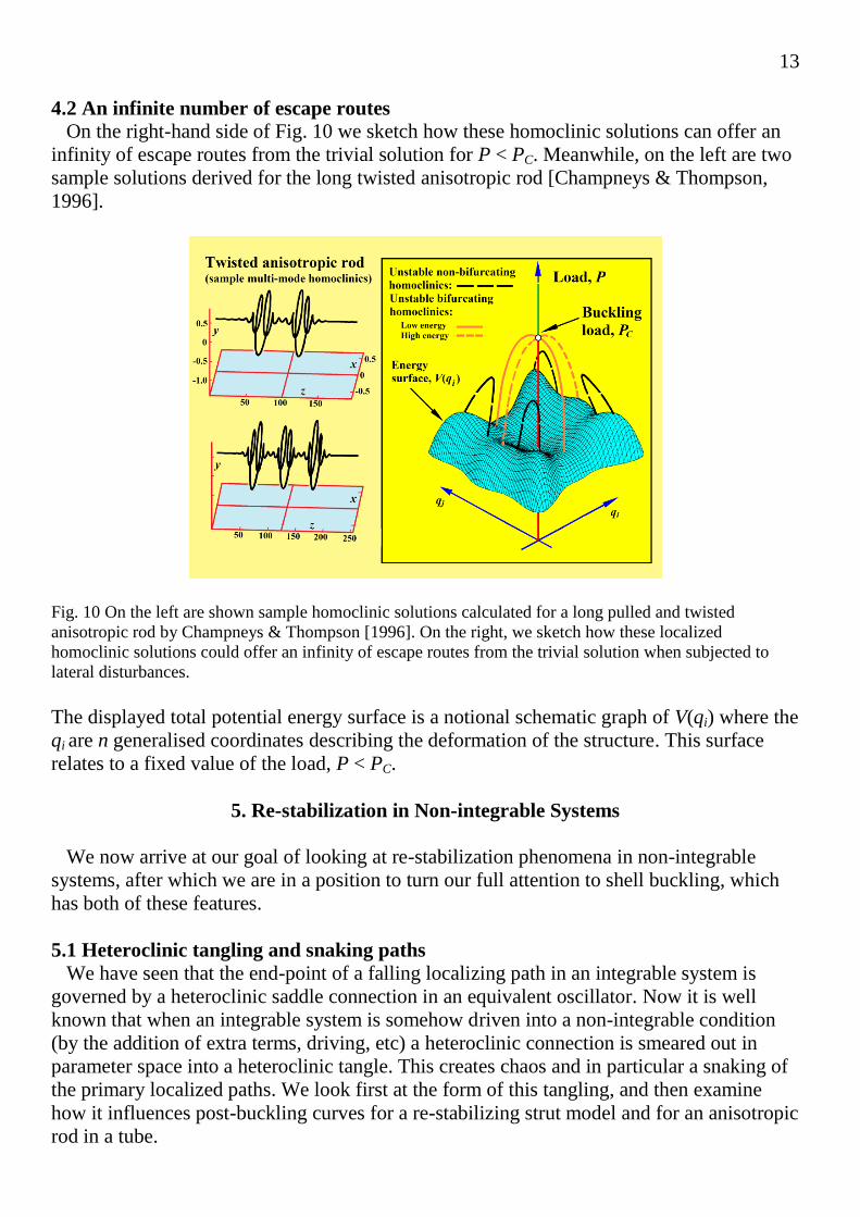
7.2 Lowest mountain-pass against buckling
We have seen in a number of examples that a localized equilibrium path falling from the
linear critical buckling load, PC, yields a lower energy pass than the falling periodic
solutions. In a very significant direct attack on the problem of the minimum energy barrier
Horak et al [2006] use sophisticated algorithms of mathematical analysis (including the
mountain pass theorem of Ambrosetti & Rabinowitz [1973]) to determine the lowest energy
barrier against disturbance-induced buckling for a long cylindrical shell under axial
compression. This corresponds to a precise localized state, and their results are shown in
Fig. 17. Here the main graph shows how the energy barrier of this state varies with the axial
load on the cylinder. The same path of states is shown in the green thumbnail on a plot of
P/PC against a measure of the deflection. Meanwhile two views of the determined shape of
the unstable localized state are shown on the right hand side of the figure, this shape
depending on the thickness to radius ratio of the shell. This is a very significant result,
which will form the basis of our later suggestions for new experimental work on shell
buckling.
We note, finally, that in this study the shell is constrained to an average end-shortening,
meaning that the ends of the cylinder are free to tilt, thereby accommodating a
circumferentially localized dimple. This is quite different from conventional shell testing,
where the rigid platens supporting the ends of the shell would normally be constrained to
remain perpendicular to the axis of the cylinder.
Fig. 17 Results of Horak et al [2006] who determined the localized solution that gives the lowest mountain-
pass escape barrier for a compressed cylindrical shell. Notice that unlike the pictures of Fig.16, the
displayed displacement is localized not only axially, but also circumferentially. It is, moreover, symmetric
in both of these directions

20
8. Cylinder Experiments Old and New
8.1 Historical scatter of experimental results
As a background to the following ideas about new experiments on shells, it is useful to
take a quick look at the historical collapse loads, many of which were obtained in the first
half of the twentieth century. The points shown in Fig. 18 are taken from the paper by Seide
et al [1960]. They show the variation of the experimental collapse loads, PEXP, as a fraction
of the classical linear theoretical values, PC, against the radius to thickness ratio of the test
specimens, R/t. This graph also shows a curve based on the old empirical knock-down
factor recommended by NASA for design purposes.
Fig. 18 Historical scatter of experimental buckling loads for an axially compressed cylindrical shell,
adapted from Seide et al [1960]. The blue curve represents the NASA knock-down factor displayed in the
box.
Similar (often the same) results taken from Brush & Almroth [1975] are displayed in a
log-log plot introduced by Chris Calladine and his co-workers [Calladine & Barber 1970,
Mandal & Calladine 2000, Zhu et al 2002] in Fig. 19(a).This shows, very convincingly, that
the best fit for these experimental results has the log-log slope of –1.48. In a series of
papers, they give a number of convincing reasons for this slope of approximately –1.5,
based on careful experiments on the self-weight buckling of a standing cylinder, with a free
unloaded top; together with some supporting theoretical results.

21
Fig. 19 (a) shows the experimental buckling loads for an axially compressed cylindrical shell, on a log-log
plot. On (b) is an identical log-log plot showing self-weight buckling tests conducted by Barber and
Mandel. Adapted from the studies of Chris Calladine and his associates [Mandal & Calladine 2000, Zhu et
al 2002].
Results of Calladine’s extended experimental studies of the self-weight buckling of free-
standing open-topped cylindrical shells are shown in Fig. 19(b). They show remarkable
consistency, and lie almost exactly on the best-fit line of Fig. 19(a) with slope
approximately –1.5. Together with some theoretical arguments, Calladine uses these and
other experiments to argue that the wide scatter of the axially compressed shells is due to
their ‘statical indeterminacy’ (which contrasts with the free shells under self-weight
loading). His argument uses the analytical "concept" of an inextensional dimple with an
elastically strained boundary, which provides a satisfactory explanation of the self-weight
data. Moreover, he recorded [Lancaster et al, 2000] a particularly high experimental
buckling load with a cylinder (R/t = 2000) by introducing boundary conditions (end discs
fastened with frictional clamps) that significantly reduced self-stress.
8.2. NASA’s current research programme
It is interesting to observe that, some 70 years after the key papers of von Karman &
Tsien [1939, 1941], shell buckling and post-buckling are still of major concern to NASA in
their design of deep-space rockets. Indeed, shell buckling is the primary factor in the design
of thin-walled launch-vehicle structures that must carry compressive loading. The core
stage design of the current Space Launch System (SLS) is, for example, completely driven
by buckling, so unduly conservative design factors which increase structural mass must be
avoided. This is emphasized by the fact that the space shuttle LH2 tank was tested to a load
greater than 140% of its design load.
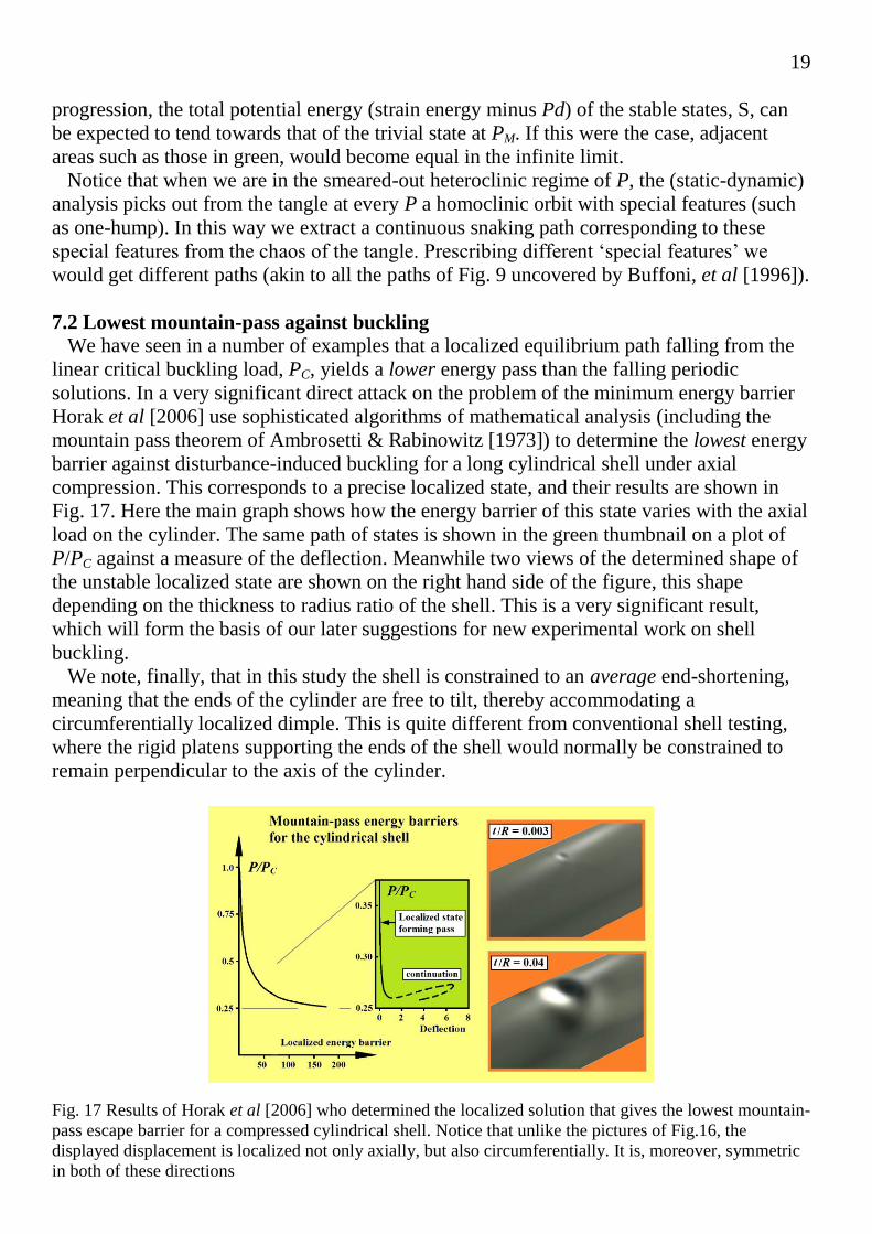
It is hardly surprising, then, that NASA is currently running a programme of full scale
tests on stiffened shells under mixed loading as illustrated in Fig. 20. This programme seeks
a rational way to replace the existing reliance on knockdown factors based on historical
experimental data. The pedigree of this data (often from the period 1920 – 1960) is difficult
22
to assess, and many of the tests are not relevant to modern launch vehicle constructions. In
particular, most NASA shells are stiffened, and so are less sensitive to imperfections than
their unstiffened counterparts.
Fig. 20 (a) and (b) illustrate NASA’s full scale test in 2013 of an unused aluminium-lithium shell left over
from the Space Shuttle programme. At 8.3m diameter, it parallels the fuel tank (namely the structural skin)
of the SLS. The stiffened and pressurized shell was compressed to an explosive buckling failure in a rigid
loading device. Dots on the cylinder allowed 20 high-speed cameras to record minute deflections under a
load of circa 106 pounds force. Shown in (c) is an artist’s impression of NASA’s Space Launch System, a
new heavy-lift vehicle standing 61m tall with an 8.5m diameter. Reproductions courtesy of NASA.
Experiments are being made on full-scale shells, left over from the Space Shuttle, but we
should note that these are relatively short (compared to the diameter), they are stiffened, and
the applied loading is complex, rather than just uniform compression. One fact that NASA
hopes to establish from this programme is that modern computer codes can accurately
predict the correct experimental failure loads of their full-scale experimental shells once
they are given the known measured imperfections. With advances in computations and
testing techniques, the principal investigator, Mark Hilburger, says that weight reductions of
about 20% are now confidently expected in the design of the projected Space Launch
System (SLS) which is due to fly in 2017. More information about this work can be found
in [Hilburger, 2013].
9. New Experimental Approach to Shock-Sensitivity
The shape of the lowest energy barrier determined by Horak et al [2006] for an axially
loaded cylindrical shell (Fig. 17) looks remarkably like the small dimple that might be
pressed into the cylinder by a researcher’s finger. This immediately suggests a new form of
experimental test on a compressed shell (of any shape) in which a lateral point load is
applied by a rigid loading device. This would seem to be a useful type of non-destructive
and non-invasive test for a shell to determine its shock-sensitivity.

23
9.1 Rigid lateral probe
The type of test configuration that we have in mind is illustrated, for a cylindrical shell, in
Fig. 21 where the lateral ‘probe’ moves slowly forward along a fixed line driven by a screw
mechanism.
Fig. 21 An impression of the proposed experimental procedure in which a rigid probe is used to construct a
lateral-load versus lateral-displacement graph, Q(q). This graph ends with Q = 0 at a free equilibrium state
of the shell, and the area under the curve gives the corresponding energy barrier. Note that at Q = 0 the
rigid probe is stabilizing a state that would otherwise be unstable for the free shell.
Here we have the controlled displacement, q, producing a passive reactive force from the
shell, Q, which is sensed by the device, giving finally the plot of Q(q). This is all to be done
at a prescribed value of the axial compressive load, P, which might itself be applied in
either a dead or rigid manner. In the simplest scenario, the Q(q) graphs might be expected to
look like those sketched on the right-hand side, the top for P greater than the Maxwell load
and the lower one for P < PM.
When the test reaches the point T, where Q = 0, we have located a free equilibrium state
of the shell, hopefully, the desired lowest mountain pass. It is interesting to note, here, that
Takei et al [2014] use an imposed lateral displacement in their computations to find the
unstable Maxwell state of a thin film. The shapes drawn as thumb-nails in the figure are
purely notional, and the shape that we would hope to find is that of Horak, shown in Fig.
17. The latter shape depends on the thickness to radius ratio, t/R, and it gives us some
intuitive feeling for whether the deformation will be within the elastic range of a given
shell. If we finally evaluate the area under the Q(q) curve, this will give us the energy
barrier that has to be overcome to cause the shell to collapse at the prescribed value of P.
Notice that if the curves have the forms drawn (with no folds or bifurcations), we can be
sure that the shell will remain stable up to T under the controlled q. If the probe is glued
(welded or fastened) to the shell, we will be able to pass point T, with the probe then
carrying a negative Q: if however the probe is just resting against the shell, a dynamic jump
from T will be observed, probably damaging the shell due to large bending strains. Clearly
gluing is preferred, to prevent this jump, but other factors must be considered. On the

24
negative side, fixing the probe to the shell may itself cause damage, and may restrict the
free deformation that we are seeking to find. In particular, it might also restrict the shell by
preventing a rotational instability. Perhaps the ideal solution would be to have an ‘equal and
opposite’ second probe inside the shell at the same point, moving at the same rate as the
probe outside.
9.2 Bifurcations and the need for control
Now under the lateral point load, the initial deflection will be symmetric in both the axial
and circumferential directions, and we should note that all of Horak’s lowest mountain
passes (localized saddle solutions) have both these symmetries. However, the story might
not be as simple as we have so far suggested. Three features that could be encountered in
the Q(q) curves are as follows. The first possibility is a vertical fold, at which dQ/dq =
infinity, from which the combined system could jump at constant q, with unknown
outcome. The second and third are symmetry-breaking pitchfork bifurcations that could
break one (or subsequently both) of the initial symmetries. A bifurcation that is sub-critical
(involving asymmetric equilibrium states at a lower value of the controlled displacement, q)
would give a jump to an unknown state: this is akin to the elastic arch under dead loading
that we shall examine in §9.3. Meanwhile a super-critical event would give a new path
which could possibly be followed in the test. Note that these symmetry-breaking
bifurcations would generate a new mode of deformation in the shell.
To overcome any such instabilities, it would be necessary (as we shall demonstrate in Fig.
25) to supplement the main probe by one or more probes that are systematically adjusted
until all their reactive forces are simultaneously zero. Jan Sieber has, for example,
developed non-invasive control methods which can follow an experimental system as it is
loaded into what would otherwise be an unstable regime. He has applied these methods
successfully to a number of systems at Bristol University [Barton & Sieber, 2013].
9.3 Analogy with a deep elastic arch
The symmetry-breaking that we have discussed is indeed well-known in the response of a
deep (as opposed to a shallow) elastic arch under dead loading [Thompson 1975, Thompson
& Hunt, 1973, 1983]. This bifurcation allows the arch to woggle-through to a large-
deflection symmetric state avoiding the high energy penalty of remaining symmetric
throughout, as is illustrated in Fig. 22. An exactly similar figure arises in the tensile
instability of the atomic lattice of a close-packed crystal, governed by Lennard-Jones
potentials, where the bifurcation triggers a symmetry-breaking shearing mode of
deformation [Thompson 1975; Thompson & Shorrock 1975].
25
Fig. 22 The buckling and snap-through of a relatively deep arch under a dead load, P, shows how a
bifurcation into an asymmetric mode allows the arch to woggle through, avoiding the large energy penalty
of remaining symmetric. Notice the schematic curved dynamic jump at the constant load, PC, that carries
the arch to its re-stabilized symmetric state. The associated energy contours are show in Fig 23.
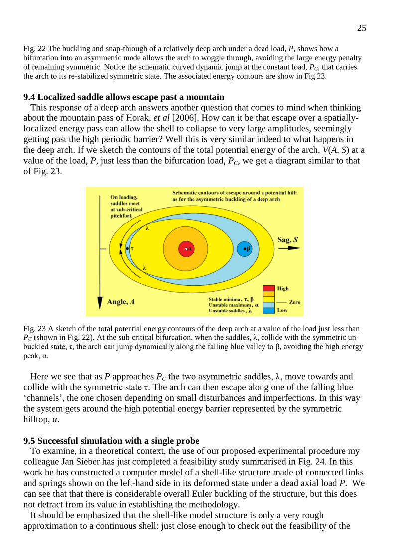
9.4 Localized saddle allows escape past a mountain
This response of a deep arch answers another question that comes to mind when thinking
about the mountain pass of Horak, et al [2006]. How can it be that escape over a spatially-
localized energy pass can allow the shell to collapse to very large amplitudes, seemingly
getting past the high periodic barrier? Well this is very similar indeed to what happens in
the deep arch. If we sketch the contours of the total potential energy of the arch, V(A, S) at a
value of the load, P, just less than the bifurcation load, PC, we get a diagram similar to that
of Fig. 23.
Fig. 23 A sketch of the total potential energy contours of the deep arch at a value of the load just less than
PC (shown in Fig. 22). At the sub-critical bifurcation, when the saddles, λ, collide with the symmetric un-
buckled state, τ, the arch can jump dynamically along the falling blue valley to β, avoiding the high energy
peak, α.
Here we see that as P approaches PC the two asymmetric saddles, λ, move towards and
collide with the symmetric state τ. The arch can then escape along one of the falling blue
‘channels’, the one chosen depending on small disturbances and imperfections. In this way
the system gets around the high potential energy barrier represented by the symmetric
hilltop, α.
9.5 Successful simulation with a single probe
To examine, in a theoretical context, the use of our proposed experimental procedure my
colleague Jan Sieber has just completed a feasibility study summarised in Fig. 24. In this
work he has constructed a computer model of a shell-like structure made of connected links
and springs shown on the left-hand side in its deformed state under a dead axial load P. We
can see that that there is considerable overall Euler buckling of the structure, but this does
not detract from its value in establishing the methodology.
It should be emphasized that the shell-like model structure is only a very rough
approximation to a continuous shell: just close enough to check out the feasibility of the

26
proposed technique, but no more. It is a dynamic model of a system of particles (with mass
and inertia) and springs forming a rectangular mesh which has been bent around to form a
cylinder. There are 24 particles on each horizontal ring and 35 rings. So far, in this very
preliminary study, there has been no attempt to fit the rotational and extensional spring
constants to match those of a continuum shell. However, the model does show all the
features of a compressed cylindrical shell in a convincing way.
In the simulations the structure is loaded by a rigid displacement q, and the passive force
Q is recorded. The first result, from a test at axial load P = 15.2 (in arbitrary units), is
shown in the top graph of Q(q). This has the expected parabola-like shape, and Q drops
continuously to zero at the end of the test, where the shell is essentially free at q = qF.
During the simulation, for each recorded equilibrium state, the (real) eigenvalues of the
Jacobian are evaluated, and if any one becomes positive an instability has been
encountered. To monitor this possibility the maximal eigenvalue is plotted (in red on the top
graph) in what will usually be a curve with crossover points, whenever a new mode
becomes the ‘softest’.
We see that the maximal eigenvalue remains less than zero throughout the first test, but it
can be seen to increase rapidly towards the end. This, then, is an example in which the Q(q)
test can be performed in a stable manner up to qF, allowing the area under the curve to be
evaluated as the required energy barrier.
Fig.24 Results of a computer simulation on a shell-like structure showing a case in which a single rigid
probe can generate the full Q(q) response, leading to the required relationship between the dead axial
compressive load, P, and the energy barrier, E. The colouring of the shell shows contours of the strain
energy density. Results supplied by Jan Sieber (Exeter University) in a private communication.
Tests under a set of P values are summarised in the red box. On the right-hand side we
show the Q(q) curves for the full range of P values, with the black curve identifying the one
at P = 15.2. On the left we show the results as P against qF and finally as P against the
energy barrier denoted by E. The sharp and rapid fall of the energy barrier as we reduce the
load P from its critical value PC is our expected result.

27
9.6 Shell simulation with a controlled bifurcation
In simulated tests on this shell-like structure with different stiffness characteristics, Jan
Sieber has produced the results shown in Fig. 25.
Fig. 25 Control of a symmetry-breaking pitch-fork bifurcation. An example of a simulation in which, under
a single probe, the Q(q) path would become unstable at a symmetry-breaking pitchfork bifurcation. This
requires the introduction of a second controlled probe, B, placed where the eigen-deflection of the
pitchfork is large. With the second probe, the test has been successfully completed. For the shell on the left,
the colouring shows contours of the strain energy density; on the right, it represents contours of (one
component of) the eigen-displacement. Results supplied by Jan Sieber (Exeter University) in a private
communication.
Here the eigenvalues showed that the Q(q) diagram had reached a symmetry-breaking
pitchfork bifurcation (whether super- or sub-critical is not known) which required the
introduction of a second control probe. This was placed where the critical eigen-vector of
the pitchfork bifurcation has a particularly large deflection. The red dots on the Q(q)
diagram indicate those states that could only be observed with the use of the extra probe, B.
This probe is tuned to provide no force, as we might, for example, demonstrate the second
buckling mode of a pin-ended strut by lightly holding the centre between two fingers. One
such controlled state is illustrated by the left-hand cylinder. Meanwhile, on the right, is a
view of the symmetric state at the pitchfork with the addition of the suitably magnified
eigen-vector. This shows that the pitchfork has violated the up-down symmetry (but not the
circumferential symmetry). Notice that the deflection curve has been continued past the Q =
0, q = qF free state condition. Albeit conducted on a computer, this is an excellent and
encouraging ‘proof of concept’ for our proposed experiments.

28
10. Concluding remarks
The characteristics of post-bifurcation equilibria that we have described in the theoretical
sections of this paper have wide applications in localization studies in solid and fluid
mechanics, and in pattern formation by Turing instabilities in chemical and biological
kinetics [Dawes, 2010]. Meanwhile, the Maxwell load is appearing in many guises, in for
example the recent study by Cao and Hutchinson [2012] of the surface wrinkling of a
compressed half-space, which is extremely imperfection-sensitive, with close parallels to
the behaviour of the cylindrical shell.
The theory has revealed a sudden onset of ‘shock-sensitivity’ in the buckling of
compressed shells and shell-like structures, which is an important design consideration for
real structures in noisy operational environments. To detect this experimentally in a model
or prototype structure, we have proposed a novel technique of controlled non-destructive
testing, which looks particularly promising. No such experiment has been conducted so far,
but Jan Sieber’s simulations are a very promising ‘proof of concept’. His work also
demonstrates the need for extra control points, a single one of which successfully inhibited
a pitch-fork instability. Looking to the future, it may be that the theoretical techniques
employed by Horak et al [2006] can be adapted to work in an experimental environment
under multiple controls.
Acknowledgements
I would like to thank the following for comments, suggestions and help during the
preparation of this paper: Alan Champneys (Bristol), Allan McRobie (Cambridge), Chris
Calladine (Cambridge), David Barton (Bristol), David Wagg (Sheffield), Gabriel Lord
(Herriot Watt), Gert van der Heijden (UCL), Giles Hunt (Bath), Jan Sieber (Exeter), John
Hutchinson (Harvard), Jonathan Dawes (Bath), Lawrence Virgin (Duke), Mark Hilburger
(NASA), Mark Peletier (Eindhoven). A particular impetus came from a small and informal
brain-storming session that Giles Hunt organized at Bath this year.
References
Ambrosetti, A. & Rabinowitz, P. H. [1973] Dual variational methods in critical point theory and
applications, J. Funct. Anal., 14, 349–381.
Babcock Jr., C. D. [1967] The influence of the testing machine on the buckling of cylindrical shells under
axial compression, Int. J. Solids Struct. 3, 809-17.
Barton, D. A. W., Sieber, J. [2013] Systematic experimental exploration of bifurcations with noninvasive
control, Phys. Rev. E 87, 052916.
Beck, M., Knobloch, J., Lloyd, D. J. B., Sandstede, B., Wagenknecht, T. [2009] Snakes, ladders, and isolas of
localized patterns. SIAM J. Math. Anal., 41 (3) 936–972.
Brush, D. O., Almroth, B .O. [1975] Buckling of bars, plates and shells. McGraw-Hill, New York.
Budd, C. J., Hunt, G. W. & Kuske, R. [2001] Asymptotics of cellular buckling close to the Maxwell load,
Proc. R. Soc. A, 457, 2935–2964.

29
Buffoni, B., Champneys, A. R. & Toland, J. F. [1996] Bifurcation and coalescence of a plethora of homoclinic
orbits for a hamiltonian system. J. Dynamics Difl Equat. 8, 221-281.
Burke, J. & Knobloch, E. [2007] Snakes and ladders: localized states in the Swift-Hohenberg equation,
Phys. Lett. A 360, 681- 688.
Bushnell, D. [2014] Shell buckling, website, http://shellbuckling.com/index.php
Calladine, C. R., Barber, J. N. [1970] Simple experiments on self-weight buckling of open cylindrical
shells. Journal of Applied Mechanics, Trans. ASME, 37, 1150–1151.
Cao, Y. & Hutchinson, J. W. [2012] From wrinkles to creases in elastomers: the instability and imperfection-
sensitivity of wrinkling, Proc. R. Soc. A 468, 94–115.
Champneys, A. R. & Thompson, J. M. T. [1996] A multiplicity of localized buckling modes for twisted rod
equations, Proc. R. Soc., A 452, 2467-2491.
Champneys, A. R., Hunt, G. W. & Thompson, J. M. T. (editors) [1999] Localization and Solitary Waves in
Solid Mechanics, World Scientific, Singapore. (Expanded version of a theme issue of Phil. Trans. Roy. Soc. A,
Vol 355, No 1732, 1997).
Croll, J. G. A. & Batista, R. C. [1981] Explicit lower bounds for the buckling of axially loaded cylinders,
Int. J. Mech. Sci. 23, 331-343.
Dawes, J. H. P. [2010] The emergence of a coherent structure for coherent structures: localized states in
nonlinear systems. Phil. Trans. R. Soc. A 368, 3519–3534 (doi:10.1098/rsta.2010.0057)
Elishakoff, I. [2012] Probabilistic resolution of the twentieth century conundrum in elastic stability, Thin-
walled structures, 59, 35-57 (DOI: 10.1016/j.tws.2012.04.002)
Friedrichs, K. O. [1941] On the minimum buckling load for spherical shells, Applied Mechanics, Theodore
von Karman Anniversary Volume, pp. 258-272. California Institute of Technology, Pasadena, 1941.
Hilburger, M. (Principal Investigator) [2013] Launch vehicle shell buckling knockdown factors testing
underway, http://www.nasa.gov/offices/nesc/home/Feature_ShellBuckling.html#.U2bJi1fN7qw
Hunt, G. W., Lord, G. J. & Champneys, A. R. [1999] Homoclinic and heteroclinic orbits underlying the
post-buckling of axially-compressed cylindrical shells. Comput. Methods Appl. Mech. Eng., 170, 239–251.
Horak, J., Lord, G. J. & Peletier, M. A. [2006] Cylinder buckling: the mountain pass as an organizing centre,
SIAM J. Appl. Math. 66, 1793–1824.
Hunt, G. W. & Lucena Neto, E. [1993] Maxwell critical loads for axially loaded cylindrical shells. ASME J.
Appl. Mech., 60(3), 702-706.
Hunt, G. W. [2011] Reflections and symmetries in space and time, IMA Journal of Applied Mathematics
76, 2−26. (doi:10.1093/imamat/hxq063).
Hunt, G. W., Bolt, H. M. & Thompson, J. M. T. [1989] Structural localization phenomena and the dynamical
phase-space analogy, Proc. R. Soc., A 425, 245-267.
Hunt, G. W., Lord, G. J. & Peletier, M.A. [2003] Cylindrical shell buckling: a characterization of
localization and periodicity, Discrete & Continuous Dynamical Systems, Series B, 3, 505–518.

30
Hunt, G. W., Peletier, M. A., Champneys, A. R., Woods, P. D., Ahmer Wadee, M., Budd, C. J. & Lord, G.
J. [2000] Cellular buckling in long structures, Nonlinear Dyn. 21, 3–29. (doi:10.1023/A:1008398006403)
Koiter, W. T. [1945] On the stability of elastic equilibrium, Dissertation, Delft, Holland. (An English
translation is available as NASA, Tech. Trans., F 10, 833, 1967.)
Lancaster, E. R., Calladine, C. R. & Palmer, S. C. [2000] Paradoxical buckling behaviour of a thin
cylindrical shell under axial compression, Int. J. Mech. Sci. 42, 843–865.
Lord, G. J., Champneys, A. R. & Hunt, G. W. [1997] Computation of localized post buckling in long
axially-compressed cylindrical shells in Localization and Solitary Waves in Solid Mechanics (A. R.
Champneys, G. W. Hunt & J. M. T. Thompson, eds), Special Issue of Phil. Trans. R. Soc., A, 355, 2137–
2150.
Mandal, P. & Calladine, C. R. [2000] Buckling of thin cylindrical shells under axial compression, Int. J.
Solids & Structures, 37, 4509-4525.
Seide, P., Weingarten, V. I., Morgan, E. J., [1960] The development of design criteria for elastic stability of
thin shell structures. Final Report: STL/TR-60-0000-19425, Space Technology Laboratories, Inc., Los
Angeles, CA, December.
Takei, A., Jin, L., Hutchinson, J. W. & Fujita, H. [2014] Ridge localizations and networks in thin films
compressed by the incremental release of a large equi-biaxial pre-stretch in the substrate, Adv. Mater., 26,
4061–4067.
Thompson, J. M. T. [1975] Experiments in catastrophe, Nature, 254, 392-395.
Thompson, J. M. T. & Champneys, A. R. [1996] From helix to localized writhing in the torsional post-
buckling of elastic rods, Proc. R. Soc., A 452, 117-138.
Thompson, J. M. T. & Hunt, G. W. [1973] A general theory of elastic stability, Wiley, London.
Thompson, J. M. T. & Hunt, G. W. [1983] On the buckling and imperfection-sensitivity of arches with and
without prestress, Int. J. Solids & Structures, 19, 445-459.
Thompson, J. M. T. & Shorrock, P. A. [1975] Bifurcational instability of an atomic lattice, J. Mech. Phys.
Solids, 23, 21-37.
Thompson, J. M. T. & Stewart, H. B. [1986] Nonlinear dynamics and chaos, (expanded second edition, 2002)
Wiley, Chichester. (Translations: Japanese, Italian.)
Thompson, J. M. T. & van der Heijden, G. H. M. [2014] Quantified “shock-sensitivity” above the Maxwell
load, Int. J. Bifurcation and Chaos, 24 (3), 1430009.
Tsien, H. S. [1942] Theory for the buckling of thin shells, J. Aero. Sci., 9, 373-384.
Tsien, H. S. [1947] Lower buckling load in the non-linear buckling theory for thin shells, Quart. Appl.
Math. 5, 236–7.
van der Heijden, G. H. M. & Thompson, J. M. T. [2000] Helical and localized buckling in twisted rods: a
unified analysis of the symmetric case, Nonlinear Dynamics, 21, 71-99.

31
van der Heijden, G. H. M. [2001] The static deformation of a twisted elastic rod constrained to lie on a
cylinder, Proc. R. Soc. A 457, 695-715.
van der Heijden, G. H. M., Champneys, A. R. & Thompson, J. M. T. [2002] Spatially complex localization in
twisted elastic rods constrained to a cylinder, Int. J. Solids & Structures, 39, 1863-1883.
von Karman, T. V. & Tsien, H. S. [1939] The buckling of spherical shells by external pressure, J. Aero.
Sci., 7, 43-50.
von Karman, T. V. & Tsien, H. S. [1941] The buckling of thin cylindrical shells under axial compression. J.
Aero. Sci., 8, 303–312.
Woods, P. D. & Champneys, A. R. [1999] Heteroclinic tangles and homoclinic snaking in the unfolding of a
degenerate reversible Hamiltonian–Hopf bifurcation, Physica D, 129, 147–170.
Yamada, S. & Croll, J. G. A. [1999] Contributions to understanding the behaviour of axially compressed
cylinders. ASME J. Appl. Mech., 66, 299–309.
Yamaki, N. (1984) Elastic stability of circular cylindrical shells, volume 27 of Applied Mathematics and
Mechanics. Elsevier, Amsterdam, Netherlands.
Zhu, E., Mandal, P., Calladine, C. R. [2002] Buckling of thin cylindrical shells: an attempt to resolve a
paradox, Int. J. Mech. Sci., 44, 1583-1601. ( DOI: 10.1016/S0020-7403(02)00065-6).
xxxxxxxxxxxxxxxxxxxx Finished manuscript, 10/09/2014 FC xxxxxxxxxxxxxxxxxx


![Advances in Shell Buckling: Theory and Experimentsucess21/[214] Advances, shells IJBC 2015 [e-pub].pdf · January 23, 2015 14:36 WSPC/S0218-1274 1530001 Advances in Shell Buckling:](https://static.fdocuments.in/doc/165x107/5ab30c3f7f8b9a6b468e0b03/advances-in-shell-buckling-theory-and-ucess21214-advances-shells-ijbc-2015.jpg)