Advances in Robotics an et a Adv Robot Autom
10
Volume 4 • Issue 2 • 1000137 Open Access Research Article Wang et al., Adv Robot Autom 2015, 4:2 DOI: 10.4172/2168-9695.1000137 Keywords: Hexapod robot; Eccentric wheel; Gas detection; Tripod gait; Hexapod gait; Motion analysis Introduction A hexapod robot is a robot that has six legs to walk or move. It is well known that a robot can be statically stable on three or more legs. Since a hexapod robot has several legs, it has a great deal of flexibility in how it can move. If some legs become disabled, the robot may still be able to walk. Furthermore, not all of the robot’s legs are needed for stability; other legs are free to reach new foot placements or manipulate a payload. Also, the robot is easily programmed to move around because it can be configured to many types of gaits. ere are various designs of hexapod robots with certain functions and advantages. For instance, hexapod robots have been sketched in eight different designs, and every de- sign has its different criteria, specifications, shapes, advantages and disadvantages [1]. Many hexapod robots are biologically inspired by hexapoda locomotion [2-10]. Hexapods may be used to test biological theories about insect locomotion, motor control, and neurobiology. Hexapod designs vary in leg arrangement. Insect inspired robots are typically laterally symmetric. Typically, individual legs range from two to six degrees of freedom. Hexapod feet are typically pointed, but can also be tipped with adhesive material to help climbing walls or wheels so the robot can drive quickly when the ground is flat. e researchers [6] developed a sixlegged walking robot that is capable of basic mobility tasks such as walking forward, backward, rotating in place and raising or lowering the body height. e authors described the first implementation of the neurobiological mechanisms in a physical hexapod robot that is capable of generating adaptive stepping actions with the same underlying control method as an insect [7]. Hexapod robots can be developed to undertake some interesting tasks. For instance, a kind of six-legged robot was developed by Ramesh and Kumar to monitor and perform household tasks independently. e robot legs movement or method of forward motion using legs is called gait. Most oſten, a hexapod robot is controlled by gaits, which allow the robot to move forward, turn, and perhaps side-step. One important issue in the development of hexapod robots is to consider the motion and develop proper gaits for the robots [10-22]. For instance, feasible gait patterns were developed by Belter and Skrzypczynski [10] to control a real hexapod walking robot. e use of hybrid genetic gravitational algorithm for generation of the gait for the hexapod robot was described by Seljanko [12]. Gaits for a hexapod robot are oſten stable, even in slightly rocky and uneven terrain. ere are varieties of gaits available. Some of the most common gaits are as follows: (1) alternating tripod gait; (2) quadruped; and (3) crawl. e famous gait used by hexapod robot is the tripod gait. In the tripod gait, there are always three feet of hexapod in contact with the ground. For example, the hexapod robots developed, were used this alternating tripod gait [17-20]. Motion of a hexapod robot may also be nongaited, which means the sequence of leg motions is not fixed, but rather chosen by the computer in response to the sensed environment. is may be most helpful in very rocky terrain, but existing techniques for motion planning are computationally expensive. As mentioned by Rashid et al. [1], hexapod robots can be designed with certain functions and advantages. Most hexapod robots were designed with only legs. Some hexapod robots were designed with manoeuvrable wheels or combination of legs and wheels [5]. In general, the movement of robot by legs is good for rocky and uneven terrain. But the movement of robot by the wheels is faster than the movement of the robot by legs [1]. e RHex robot could be an exception because the motion of its six C shape legs is similar to the rotation of wheels [2-4]. e RHex robot has a lot of excellent performance such as (1) running on reasonably flat, natural terrain at speeds up to 6 body lengths per second (just over 2.7 m/s); (2) climbing a wide range of stairs and slopes up to 45 degrees; (3) traversing obstacles as high as *Corresponding author: Jiang Q, Comau Inc., MI, USA. and Southwest University, Chongqing, China. Tel: +1(248)200-6451; E-mail: [email protected] Received August 23, 2015; Accepted September 22, 2015; Published September 28, 2015 Citation: Yujun Wang, Can Fang, Qimi Jiang (2015) Motion Analysis of Hexapod Robot with Eccentric Wheels. Adv Robot Autom 4: 137. doi: 10.4172/2168- 9695.1000137 Copyright: © 2015 Yujun Wang, et al. This is an open-access article distributed under the terms of the Creative Commons Attribution License, which permits unrestricted use, distribution, and reproduction in any medium, provided the original author and source are credited. Abstract A new concept for developing hexapod robots using eccentric wheels is proposed in this work. Compared with the RHex robot, the proposed hexapod robot can greatly reduce the bumping of the robot body in both smooth ground and rocky terrain. Also, the developed hexapod robot possesses significant advantages over those with common circular wheels in traversing rocky and uneven terrain. Also, the control of the proposed hexapod robot is simple because each eccentric wheel has only one degree of freedom. This work focuses on the kinematics analysis of the proposed hexapod robot. Two types of gaits respectively named as the alternating tripod gait and the hexapod gait are proposed. With the alternating tripod gait, the robot can move continuously. But the hexapod gait is helpful in overcoming the resistant torque caused by the weight on the eccentric wheels. Besides, the effect of the eccentricity on the motion of the robot is analysed. The proposed hexapod robot can be used to detect the gas in underground mines. Motion Analysis of Hexapod Robot with Eccentric Wheels Yujun Wang 1 , Can Fang 1 and Qimi Jiang 1,2* 1 School of Computer and Information Science, Southwest University, Chongqing, China 2 Comau Inc, MI, USA Advances in Robotics & Automation A d v a n c e s i n R o b o t i c s & A u t o m a t i o n ISSN: 2168-9695 Adv Robot Autom, an open access journal ISSN: 2168-9695
Transcript of Advances in Robotics an et a Adv Robot Autom
Volume 4 • Issue 2 • 1000137
Open AccessResearch Article
Wang et al., Adv Robot Autom 2015, 4:2 DOI: 10.4172/2168-9695.1000137
Keywords: Hexapod robot; Eccentric wheel; Gas detection; Tripodgait; Hexapod gait; Motion analysis
IntroductionA hexapod robot is a robot that has six legs to walk or move. It is
well known that a robot can be statically stable on three or more legs. Since a hexapod robot has several legs, it has a great deal of flexibility in how it can move. If some legs become disabled, the robot may still be able to walk. Furthermore, not all of the robot’s legs are needed for stability; other legs are free to reach new foot placements or manipulate a payload. Also, the robot is easily programmed to move around because it can be configured to many types of gaits. There are various designs of hexapod robots with certain functions and advantages. For instance, hexapod robots have been sketched in eight different designs, and every de- sign has its different criteria, specifications, shapes, advantages and disadvantages [1].
Many hexapod robots are biologically inspired by hexapoda locomotion [2-10]. Hexapods may be used to test biological theories about insect locomotion, motor control, and neurobiology. Hexapod designs vary in leg arrangement. Insect inspired robots are typically laterally symmetric. Typically, individual legs range from two to six degrees of freedom. Hexapod feet are typically pointed, but can also be tipped with adhesive material to help climbing walls or wheels so the robot can drive quickly when the ground is flat. The researchers [6] developed a sixlegged walking robot that is capable of basicmobility tasks such as walking forward, backward, rotating in placeand raising or lowering the body height. The authors described thefirst implementation of the neurobiological mechanisms in a physicalhexapod robot that is capable of generating adaptive stepping actionswith the same underlying control method as an insect [7].
Hexapod robots can be developed to undertake some interesting tasks. For instance, a kind of six-legged robot was developed by Ramesh and Kumar to monitor and perform household tasks independently.
The robot legs movement or method of forward motion using legs is called gait. Most often, a hexapod robot is controlled by gaits, which allow the robot to move forward, turn, and perhaps side-step. One important issue in the development of hexapod robots is to consider the motion and develop proper gaits for the robots [10-22]. For instance, feasible gait patterns were developed by Belter and Skrzypczynski [10] to control a real hexapod walking robot. The use of hybrid genetic
gravitational algorithm for generation of the gait for the hexapod robot was described by Seljanko [12].
Gaits for a hexapod robot are often stable, even in slightly rocky and uneven terrain. There are varieties of gaits available. Some of the most common gaits are as follows: (1) alternating tripod gait; (2) quadruped; and (3) crawl. The famous gait used by hexapod robot is the tripod gait. In the tripod gait, there are always three feet of hexapod in contact with the ground. For example, the hexapod robots developed, were used this alternating tripod gait [17-20].
Motion of a hexapod robot may also be nongaited, which means the sequence of leg motions is not fixed, but rather chosen by the computer in response to the sensed environment. This may be most helpful in very rocky terrain, but existing techniques for motion planning are computationally expensive.
As mentioned by Rashid et al. [1], hexapod robots can be designed with certain functions and advantages. Most hexapod robots were designed with only legs. Some hexapod robots were designed with manoeuvrable wheels or combination of legs and wheels [5]. In general, the movement of robot by legs is good for rocky and uneven terrain. But the movement of robot by the wheels is faster than the movement of the robot by legs [1]. The RHex robot could be an exception because the motion of its six C shape legs is similar to the rotation of wheels [2-4].
The RHex robot has a lot of excellent performance such as (1) running on reasonably flat, natural terrain at speeds up to 6 body lengths per second (just over 2.7 m/s); (2) climbing a wide range of stairs and slopes up to 45 degrees; (3) traversing obstacles as high as
*Corresponding author: Jiang Q, Comau Inc., MI, USA. and Southwest University, Chongqing, China. Tel: +1(248)200-6451; E-mail: [email protected]
Received August 23, 2015; Accepted September 22, 2015; Published September 28, 2015
Citation: Yujun Wang, Can Fang, Qimi Jiang (2015) Motion Analysis of Hexapod Robot with Eccentric Wheels. Adv Robot Autom 4: 137. doi: 10.4172/2168-9695.1000137
Copyright: © 2015 Yujun Wang, et al. This is an open-access article distributed under the terms of the Creative Commons Attribution License, which permits unrestricted use, distribution, and reproduction in any medium, provided the original author and source are credited.
AbstractA new concept for developing hexapod robots using eccentric wheels is proposed in this work. Compared with
the RHex robot, the proposed hexapod robot can greatly reduce the bumping of the robot body in both smooth ground and rocky terrain. Also, the developed hexapod robot possesses significant advantages over those with common circular wheels in traversing rocky and uneven terrain. Also, the control of the proposed hexapod robot is simple because each eccentric wheel has only one degree of freedom. This work focuses on the kinematics analysis of the proposed hexapod robot. Two types of gaits respectively named as the alternating tripod gait and the hexapod gait are proposed. With the alternating tripod gait, the robot can move continuously. But the hexapod gait is helpful in overcoming the resistant torque caused by the weight on the eccentric wheels. Besides, the effect of the eccentricity on the motion of the robot is analysed. The proposed hexapod robot can be used to detect the gas in underground mines.
Motion Analysis of Hexapod Robot with Eccentric WheelsYujun Wang1, Can Fang1 and Qimi Jiang1,2*
1School of Computer and Information Science, Southwest University, Chongqing, China2Comau Inc, MI, USA
Advances in Robotics & AutomationAd
vanc
es in
Robotics &Automation
ISSN: 2168-9695
Adv Robot Autom, an open access journal ISSN: 2168-9695
Citation: Yujun Wang, Can Fang, Qimi Jiang (2015) Motion Analysis of Hexapod Robot with Eccentric Wheels. Adv Robot Autom 4: 137. doi: 10.4172/2168-9695.1000137
Page 2 of 10
Volume 4 • Issue 2 • 1000137
20 cm (about twice RHex’s leg clearance) and badly broken terrain with large rocks or obstacles; (4) walking and running upside down; (5) flipping itself over to recover nominal body orientation; (6) leaping across ditches up to 30 cm wide.
However, the RHex robot is not suitable for working in underground mines to detect gas. The reasons are: (1) Its violent bumping and collision of its body with the rocky terrain will be easy to cause sparks leading to explosion in detecting the gas in underground mines. (2) In such an application, the power of every motor is quite limited (only 3 watts). The motors used for the RHex robot cannot be so small. Otherwise, its powerful performance will be greatly compromised. (3) The gas detective robot has a sensor on top of a stick about 1.5 meters high, which stretches up from the robot body. So, walking and running upside down, flipping and leaping are not allowed even if these are good performance of the RHex robot.
In order to develop such a gas detective robot working in underground mines, a new concept for developing hexapod robots using eccentric wheels is proposed in this work. Compared with the RHex robot, the proposed hexapod robot can greatly reduce the bumping of the robot body in both smooth ground and rocky terrain. Also, the developed hexapod robot possesses significant advantages over those with common circular wheels in traversing rocky and uneven terrain. Also, the control of the proposed hexapod robot is simple because each eccentric wheel has only one degree of freedom.
This work focuses on the kinematics analysis of the proposed hexapod robot. In Section 2, the prototype of the proposed hexapot robot with eccentric wheels is briefly introduced. In Section 3, the tripot gait for both straight walking and turning is proposed. In Section 4, the hexapot gait is described. In Section 5, the motion analysis of the proposed hexapot robot is conducted. In Section 6, the advantages of the proposed hexapot robot over both RHex robot and those with common circular wheels are given in several situations. Finally in Section 7, some conclusions and discussions are summarized.
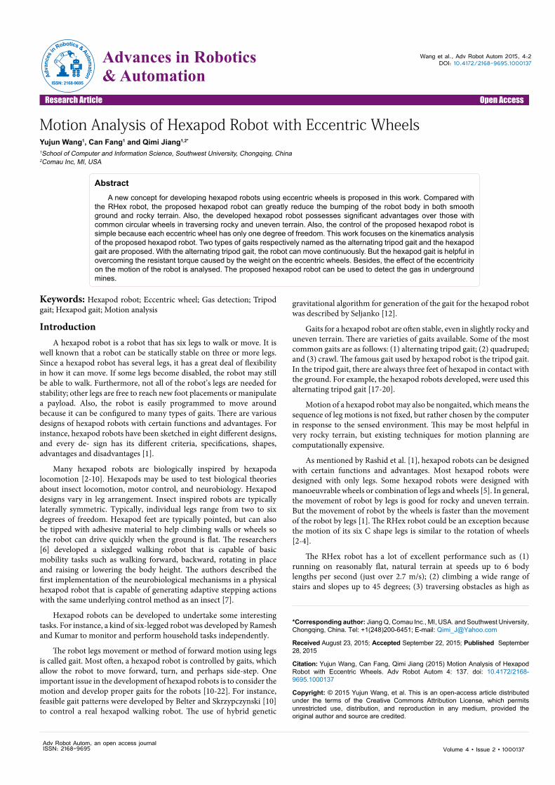
Hexapod Robot with Eccentric WheelsAs shown in Figure 1, the developed hexapod robot with eccentric
wheels is traversing an obstacle. This robot is actually symmetric in three directions. First, the robot is symmetric about the central vertical section plane in the moving direction: three eccentric wheels (#1, #2 and #3) at the left- hand side and three eccentric wheels (#4, #5 and #6) at the right-hand side. Second, the robot is symmetric about the vertical section plane passing through the axes of the middle eccentric wheels (#2 and #5). Third, the robot is also symmetric about the horizontal section plane passing through the axes of all six eccentric wheels. In other words, the upper and down parts of the robot are also
symmetric about the horizontal section plane passing through the axes of all six eccentric wheels. Hence, the robot is able to walk even if it is overturned. In terms of structure, the developed hexapod is quite similar to the RHex robot in which open curved legs were used.
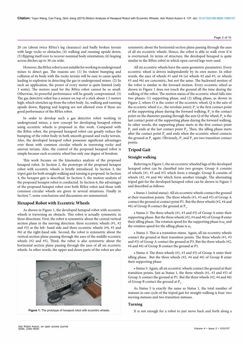
All six eccentric wheels have the same geometric parameters. Every eccentric wheel is driven independently by its own motor. In other words, the axes of wheels #1 and #4 (or wheels #2 and #5, or wheels #3 and #6) are concentric, but not the same. The backward motion of the robot is similar to the forward motion. Every eccentric wheel as shown in Figure 1 does not touch the ground all the time during the walking of the robot. The motion status of the eccentric wheel falls into two phases: (1) supporting phase, and (2) idling phase, as shown in Figure 2, where O is the center of the eccentric wheel; Q is the axis of the eccentric wheel (i.e., the revolute joint); P1 is the first contact point of the supporting phase during the forward walking; P2 is the contact point on the diameter passing through the axis Q of the wheel; P3 is the last contact point of the supporting phase during the forward walking. In other words, the supporting phase starts at the first contact point P1 and ends at the last contact point P3. Then, the idling phase starts after the contact point P3 and ends when the eccentric wheel contacts the ground at P1 again. Obviously, P1 and P3 are two transition contact points.
Tripod GaitStraight walking
Referring to Figure 1, the six eccentric wheeled legs of the developed hexapod robot can be classified into two groups: Group A consists of wheels (#1, #3 and #5) which form a triangle. Group B consists of wheels (#2, #4 and #6) which form another triangle. The alternating tripod gait for the developed hexapod robot can be shown in Figure 3 and described as follows:
• Status 1 (initial status): All six eccentric wheels contact the ground at their transition points. The three wheels (#1, #3 and #5) of Group A contact the ground at contact point P1. But the three wheels (#2, #4 and #6) of Group B contact the ground at P3.
• Status 2: The three wheels (#1, #3 and #5) of Group A enter theirsupporting phase. But the three wheels (#2, #4 and #6) of Group B enter their idling phase. The rotation speed for the supporting phase is ωs and the rotation speed for the idling phase is ωi.
• Status 3: This is a transition status. Again, all six eccentric wheelscontact the ground at their transition points. The three wheels (#1, #3 and #5) of Group A contact the ground at P3. But the three wheels (#2, #4 and #6) of Group B contact the ground at P1.
• Status 4: The three wheels (#1, #3 and #5) of Group A enter theiridling phase. But the three wheels (#2, #4 and #6) of Group B enter their supporting phase.
• Status 5: Again, all six eccentric wheels contact the ground at their transition points. Just as Status 1, the three wheels (#1, #3 and #5) of Group A contact the ground at P1. But the three wheels (#2, #4 and #6) of Group B contact the ground at P3.
As Status 5 is exactly the same as Status 1, the total number of statuses in one cycle of the tripod gait for straight walking is four: two moving statuses and two transition statuses.
Turning
It is not enough for a robot to just move back and forth along a Figure 1: The prototype of hexapod robot with eccentric wheels.
Adv Robot Autom, an open access journal ISSN: 2168-9695
Citation: Yujun Wang, Can Fang, Qimi Jiang (2015) Motion Analysis of Hexapod Robot with Eccentric Wheels. Adv Robot Autom 4: 137. doi: 10.4172/2168-9695.1000137
Page 3 of 10
Volume 4 • Issue 2 • 1000137
pass the longer circular arc 3 1P P of the wheels before reaching P1.
• Status 3: This is a transition status. Again, all six eccentric wheelscontact the ground at their transition points. But now, the four end wheels (#1, #3, #4 and #6) contact the ground at P1. The two middle wheels (#2 and #5) contact the ground at P3.
• Status 4: The three wheels (#1, #3, and #5) of Group A enter theiridling phase. The rotation speed of two end wheels (#1 and #3) at the left-hand side is −ωi.
They start from P1 and pass the longer circular arc 1 3P P of the wheels before reaching P3. But the rotation speed of the middle wheel (#5) at the right-hand side is ωi. It starts from P3 and passes the longer circular arc 3 1P P of the wheel before reaching P1.
In the meantime, the three wheels (#2, #4, and #6) of Group B enter their supporting phase. The rotation speed of the middle wheel (#2) at the left-hand side is −ωs. Its contact point starts from P3 and passes the shorter circular arc 3 1P P of the wheel before reaching P1. As a result, the left-hand side of the robot obtains a backward speed. But the rotation speed of two end wheels (#4 and #6) at the right-hand side is ωs. Their contact points start from P1 and pass the shorter circular arc 1 3P P of the wheels before reaching P3. As a result, the right-hand side of the robot obtains a forward speed. As the left-hand side of the robot obtains a backward speed and the right-hand side of the robot obtains a forward speed, the robot is turning left.
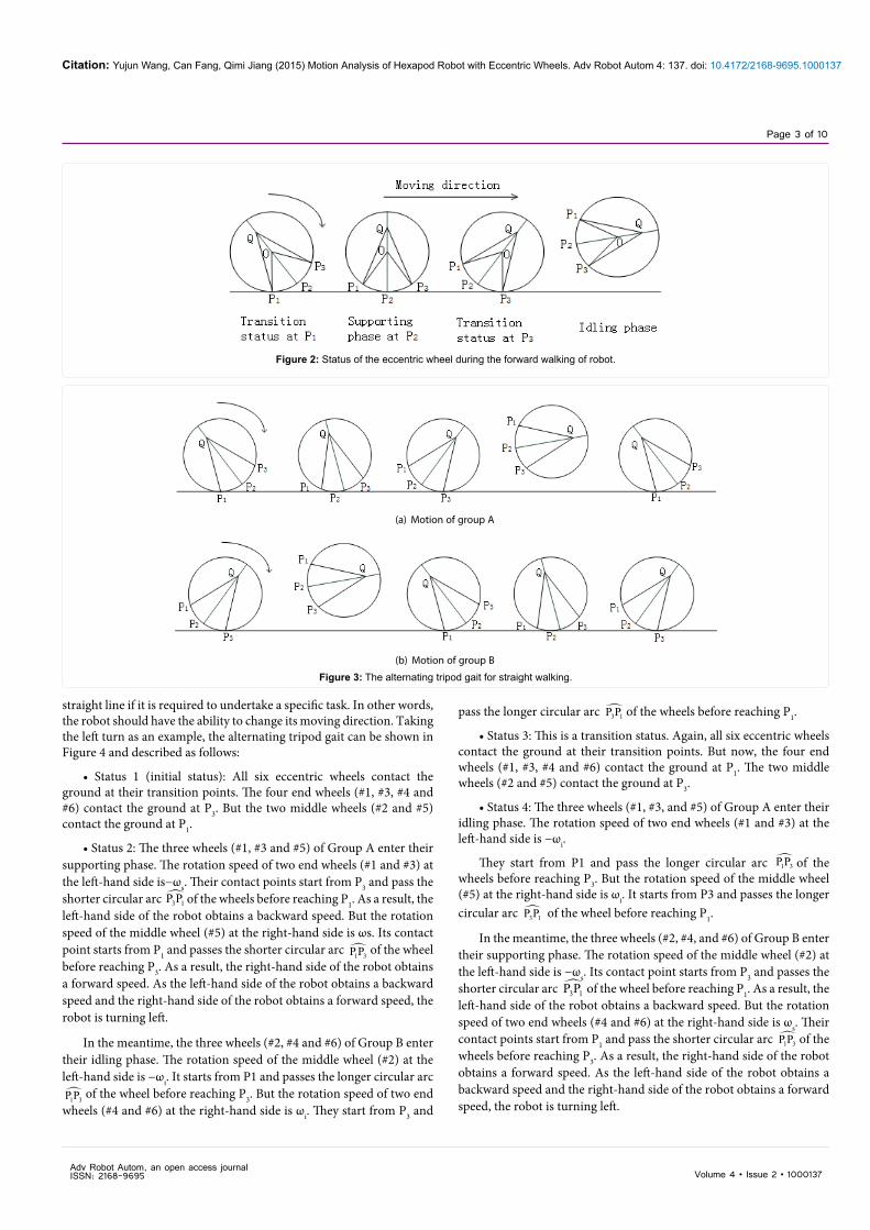
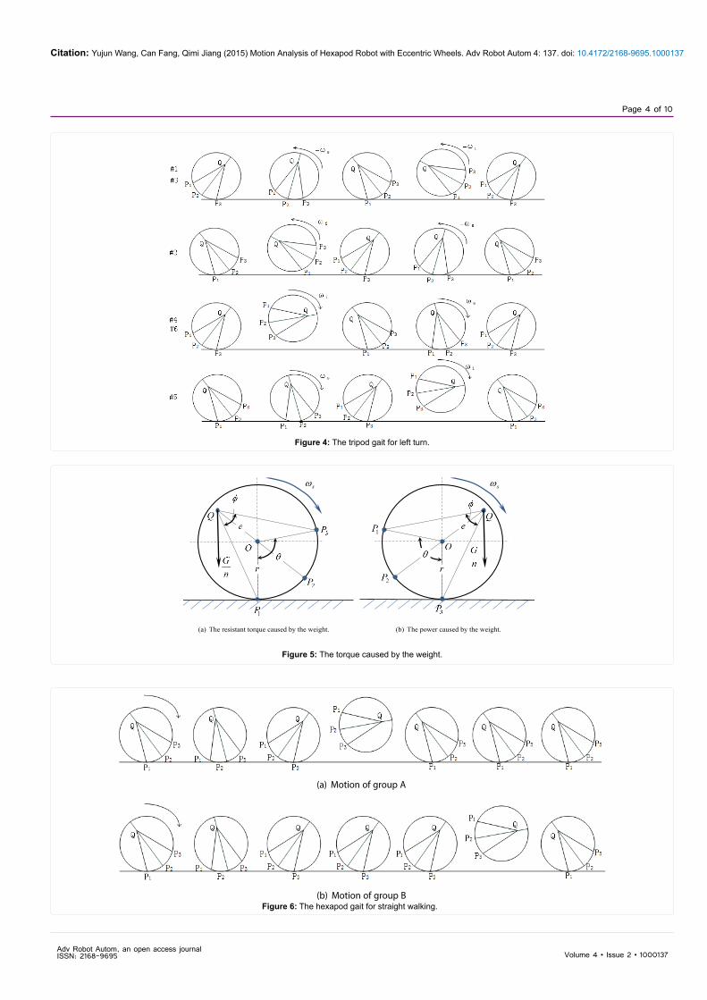
straight line if it is required to undertake a specific task. In other words, the robot should have the ability to change its moving direction. Taking the left turn as an example, the alternating tripod gait can be shown in Figure 4 and described as follows:
• Status 1 (initial status): All six eccentric wheels contact theground at their transition points. The four end wheels (#1, #3, #4 and #6) contact the ground at P3. But the two middle wheels (#2 and #5) contact the ground at P1.
• Status 2: The three wheels (#1, #3 and #5) of Group A enter theirsupporting phase. The rotation speed of two end wheels (#1 and #3) at the left-hand side is−ωs. Their contact points start from P3 and pass the shorter circular arc 3 1P P of the wheels before reaching P1. As a result, the left-hand side of the robot obtains a backward speed. But the rotation speed of the middle wheel (#5) at the right-hand side is ωs. Its contact point starts from P1 and passes the shorter circular arc
1 3P P of the wheel before reaching P3. As a result, the right-hand side of the robot obtains a forward speed. As the left-hand side of the robot obtains a backward speed and the right-hand side of the robot obtains a forward speed, the robot is turning left.
In the meantime, the three wheels (#2, #4 and #6) of Group B enter their idling phase. The rotation speed of the middle wheel (#2) at the left-hand side is −ωi. It starts from P1 and passes the longer circular arc
1 3P P of the wheel before reaching P3. But the rotation speed of two end wheels (#4 and #6) at the right-hand side is ωi. They start from P3 and
Figure 2: Status of the eccentric wheel during the forward walking of robot.
(a) Motion of group A
(b) Motion of group B
Figure 3: The alternating tripod gait for straight walking.
Adv Robot Autom, an open access journal ISSN: 2168-9695
Citation: Yujun Wang, Can Fang, Qimi Jiang (2015) Motion Analysis of Hexapod Robot with Eccentric Wheels. Adv Robot Autom 4: 137. doi: 10.4172/2168-9695.1000137
Page 4 of 10
Volume 4 • Issue 2 • 1000137
sω
(a) The resistant torque caused by the weight.
sω
(b) The power caused by the weight.
Figure 5: The torque caused by the weight.
(a) Motion of group A
(b) Motion of group BFigure 6: The hexapod gait for straight walking.
Figure 4: The tripod gait for left turn.
Adv Robot Autom, an open access journal ISSN: 2168-9695
Citation: Yujun Wang, Can Fang, Qimi Jiang (2015) Motion Analysis of Hexapod Robot with Eccentric Wheels. Adv Robot Autom 4: 137. doi: 10.4172/2168-9695.1000137
Page 5 of 10
Volume 4 • Issue 2 • 1000137
• Status 5: Again, all six eccentric wheels contact the ground at their transition points. Just as Status 1, the four end wheels (#1, #3, #4 and #6) contact the ground at P3. But the two middle wheels (#2, #5) contact the ground at P1.
As Status 5 is exactly the same as Status 1, the total number of statuses in one cycle of the tripod gait for turning is also four: two moving statuses and two transition statuses.
It can be seen that for the left turn, no matter in supporting phase or idling phase, the rotation speed of each wheel at the left-hand side of the robot is negative. But the rotation speed of each wheel at the right-hand side of the robot is positive. It can be easily to deduce that for the right turn, the rotation speed of each wheel at the left-hand side of the robot will be positive. But the rotation speed of each wheel at the right-hand side of the robot will be negative.
There are some similarity and differences between the gait for straight walking and the gait for turning. Similarity: In each case, when the three wheels of Group A form a triangle at their supporting phase, the three wheels of Group B also form another triangle at their idling phase. After that, when the three wheels of Group A form a triangle at their idling phase, the three wheels of Group B also form another triangle at their supporting phase. This is why both gaits are called as alternating tripod gaits.
Difference: In the gait for straight walking, the three wheels of each group stand at the same transition contact point (P1 or P3) at each transition status. The rotation speed of every wheel at the moving statuses is always positive. But in the gait for turning, the three wheels of the same group do not stand at the same transition contact point at the transition statuses. For instance, if the wheels (#1 and #3) at the left-hand side of the robot stand at P1, the wheel (#5) at the right-hand side stands at P3. Also, the sign of the rotation speed of the wheels at the left-hand side of the robot is different from the wheels at the right-hand side.
Hexapod GaitAs mentioned in the introduction, the proposed hexapod robot
can be used as the mining robot for detecting the gas in underground mines. Hence, the power of the motors is quite small. Otherwise, it would be easy to cause sparks that could lead to explosion. On the other hand, the weight of the robot causes a resistant torque on the eccentric wheel as shown in Figure 5a because of the eccentricity. (Of course, when the axis Q lies at the other side of the vertical diameter through the center O, the torque caused by the weight becomes a kind of power source as shown in Figure 5b. The n in Figure 5 is the number of wheels contacting the ground at the same time. For the tripot gait, n=3. In order to reduce this resistant torque caused by the weight, one solution is to increase the number n of the wheels contacting the ground. If we can make all six wheels to contact the ground at the same time (i.e., n=6), the resistant torque caused by the weight on the wheel will decrease by half. To this end, the hexapod gait is proposed in this section.
Straight walking
The hexapod gait for the developed hexapod robot can be shown in Figure 6 and described as follows:
• Status 1 (initial status): All six eccentric wheels contact the ground at their transition points P1.
• Status 2: All six wheels enter their supporting phase. This is a
moving status.
• Status 3: All six eccentric wheels contact the ground at theirtransition points P3. This is a transition status.
• Status 4: The three wheels (#1, #3 and #5) of Group A enter theiridling phase. But the three wheels (#2, #4 and #6) of Group B keep their poses at their transition points P3. This is an adjusting status.
• Status 5: The three wheels (#1, #3 and #5) of Group.
A contact the ground at their transition points P1. But the threewheels (#2, #4 and #6) of Group B still keep their poses at their transition points P3. This is a transition status.
• Status 6: The three wheels (#1, #3 and #5) of Group A keep theirposes at their transition points P1. But the three wheels (#2, #4 and #6) of Group B enter their idling phase. This is an adjusting status.
• Status 7: All six eccentric wheels contact the ground at theirtransition points P1. This is a transition status, which is exactly the same as Status 1.
As Status 7 is exactly the same as Status 1, the total number of statuses in one cycle of the hexapod gait for straight walking is six: one moving status, two adjusting statuses and three transition statuses.
Turning
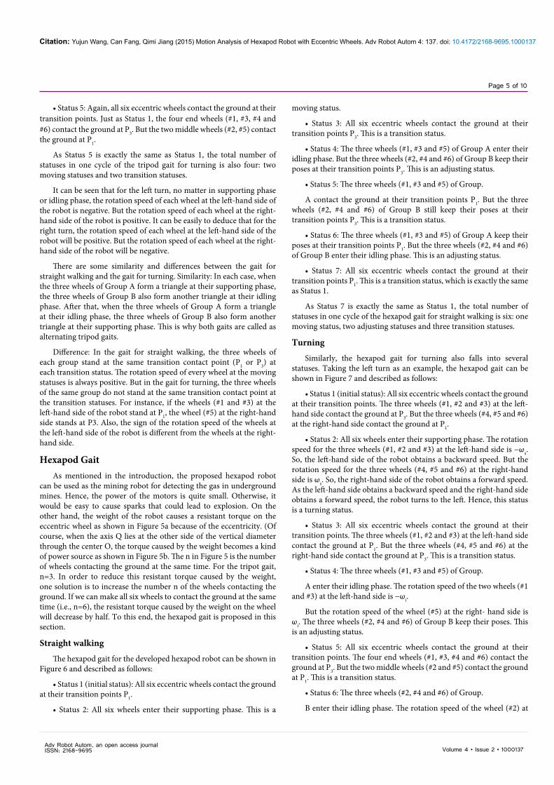
Similarly, the hexapod gait for turning also falls into several statuses. Taking the left turn as an example, the hexapod gait can be shown in Figure 7 and described as follows:
• Status 1 (initial status): All six eccentric wheels contact the ground at their transition points. The three wheels (#1, #2 and #3) at the left-hand side contact the ground at P3. But the three wheels (#4, #5 and #6) at the right-hand side contact the ground at P1.
• Status 2: All six wheels enter their supporting phase. The rotation speed for the three wheels (#1, #2 and #3) at the left-hand side is −ωs. So, the left-hand side of the robot obtains a backward speed. But the rotation speed for the three wheels (#4, #5 and #6) at the right-hand side is ωs. So, the right-hand side of the robot obtains a forward speed. As the left-hand side obtains a backward speed and the right-hand side obtains a forward speed, the robot turns to the left. Hence, this status is a turning status.
• Status 3: All six eccentric wheels contact the ground at theirtransition points. The three wheels (#1, #2 and #3) at the left-hand side contact the ground at P1. But the three wheels (#4, #5 and #6) at the right-hand side contact the ground at P3. This is a transition status.
• Status 4: The three wheels (#1, #3 and #5) of Group.
A enter their idling phase. The rotation speed of the two wheels (#1 and #3) at the left-hand side is −ωi.
But the rotation speed of the wheel (#5) at the right- hand side is ωi. The three wheels (#2, #4 and #6) of Group B keep their poses. This is an adjusting status.
• Status 5: All six eccentric wheels contact the ground at theirtransition points. The four end wheels (#1, #3, #4 and #6) contact the ground at P3. But the two middle wheels (#2 and #5) contact the ground at P1. This is a transition status.
• Status 6: The three wheels (#2, #4 and #6) of Group.
B enter their idling phase. The rotation speed of the wheel (#2) at
Adv Robot Autom, an open access journal ISSN: 2168-9695
Citation: Yujun Wang, Can Fang, Qimi Jiang (2015) Motion Analysis of Hexapod Robot with Eccentric Wheels. Adv Robot Autom 4: 137. doi: 10.4172/2168-9695.1000137
Page 6 of 10
Volume 4 • Issue 2 • 1000137
the left-hand side is −ωi. But the rotation speed of the wheels (#4 and #6) at the right-hand side is ωi. The three wheels (#1, #3 and #5) of Group A keep their poses. This is an adjusting status.
• Status 7: All six eccentric wheels contact the ground at theirtransition points. The three wheels (#1, #2 and #3) at the left-hand side contact the ground at P3. But the three wheels (#4, #5 and #6) at the right-hand side contact the ground at P1. This is a transition status, which is exactly the same as Status 1.
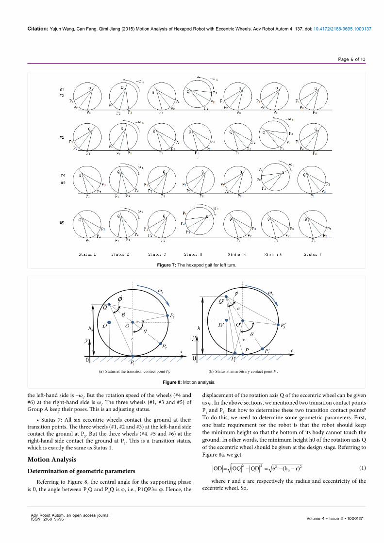
Motion AnalysisDetermination of geometric parameters
Referring to Figure 8, the central angle for the supporting phase is θ, the angle between P1Q and P3Q is φ, i.e., P1QP3= φ. Hence, the
displacement of the rotation axis Q of the eccentric wheel can be given as φ. In the above sections, we mentioned two transition contact points P1 and P3. But how to determine these two transition contact points? To do this, we need to determine some geometric parameters. First, one basic requirement for the robot is that the robot should keep the minimum height so that the bottom of its body cannot touch the ground. In other words, the minimum height h0 of the rotation axis Q of the eccentric wheel should be given at the design stage. Referring to Figure 8a, we get
2 2 2 20OD OQ QD e (h r)= − = − − (1)
where r and e are respectively the radius and eccentricity of the eccentric wheel. So,
Figure 7: The hexapod gait for left turn.
sω
y
0
(a) Status at the transition contact point P1.
sω
0
(b) Status at an arbitrary contact point P .
Figure 8: Motion analysis.
Adv Robot Autom, an open access journal ISSN: 2168-9695
Citation: Yujun Wang, Can Fang, Qimi Jiang (2015) Motion Analysis of Hexapod Robot with Eccentric Wheels. Adv Robot Autom 4: 137. doi: 10.4172/2168-9695.1000137
Page 7 of 10
Volume 4 • Issue 2 • 1000137
2 201 1
0
OD e (h r)OQD tan tan .
QD h r− − − −
∠ = =−
(2)
2 201 1
10 0
OD e (h r)P QD tan tan .
h h r− − − −
∠ = =−
(3)
From Equation (2) and (3), we get
1 3 1 2 1
2 2 2 20 01 1
0 0
P QP 2 P QP 2( OQD P QD)
e (h r) e (h r)2(tan tan .
h r h
φ
− −
= ∠ = ∠ = ∠ −∠
− − − −= −
−
(4)
2 201
1 3 1 20
e (h r)P OP 2 P OP 2tan .
h rθ − − −= ∠ = ∠ =
−(5)
Motion status of Q
Suppose that the eccentric wheel contacts the ground at P1 at the initial moment (t=0) as shown in Figure 8a. It will contact the ground at point p at the moment t as shown in Figure 8b from which we get
' ' ' ' ' ' ' ' '2
s
O D O Q sin O Q D esin P O P
esin( / 2 t).θ ω
= ∠ = ∠
= − (6)
' ' ' ' ' ' ' ' '2
s
Q D O Q cos O Q D ecos P O P
ecos( / 2 t).θ ω
= ∠ = ∠
= − (7)
The displacement of the center O of the eccentric wheel is' '
O 1 s Or P O P r t, r,ω= ∠ = =x y (8)
Hence, the displacement of the rotation axis Q of the eccentric wheel can be given as
' 'O
2 2s 0 s
' 'O s
( OD O D )
r t e (h r) esin( / 2 t),
y y Q D r ecos( / 2 t)
ω θ ω
θ ω
= + −
= + − − − −
= + = + −
x x
(9)
Differentiating Eq.(9) with respect to time t, the velocity of Q can be given as
cos( / 2 )sin( / 2 ).
ω ω θ ωω θ ω
= = + −
= = −
x s s s
y s s
v x r e tv y e t
(10)
Differentiating Eq.(10) with respect to time t, the acceleration of Q can be given as
2
2
sin( / 2 )
cos( / 2 ).
ω θ ω
ω θ ω
= = −
= = − −
x s s
y s s
a x e t
a y e t (11)
Motion status of the robot
For straight walking, no matter which gait (the tripot gait or the hexapod gait) is used, all wheels in the supporting status have the same motion status. Hence, the motion status of the robot body is exactly the same as the motion of the rotation axis Q given by Equation (9) – (11).
For turning, the displacement, velocity and acceleration of the robot body in the vertical direction are respectively given as yQ, yQ , yQ which are the same as the straight walking. But in the horizontal direction, considering the symmetric structure of the robots, the turning (rotation in the horizontal plane) speed and acceleration can be given as
2 /2 /
ωα ω=
= =x r
x r
v Wa W
(12)
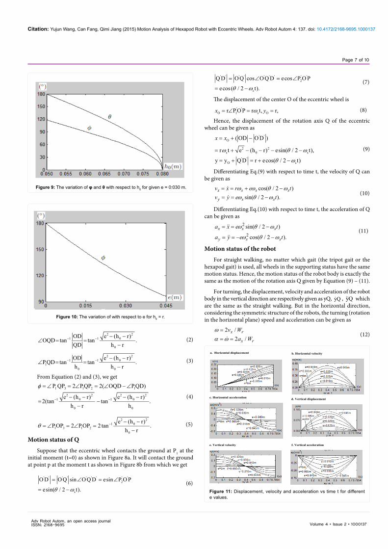
Figure 9: The variation of φ and θ with respect to h0 for given e = 0:030 m.
Figure 10: The variation of with respect to e for h0 = r.
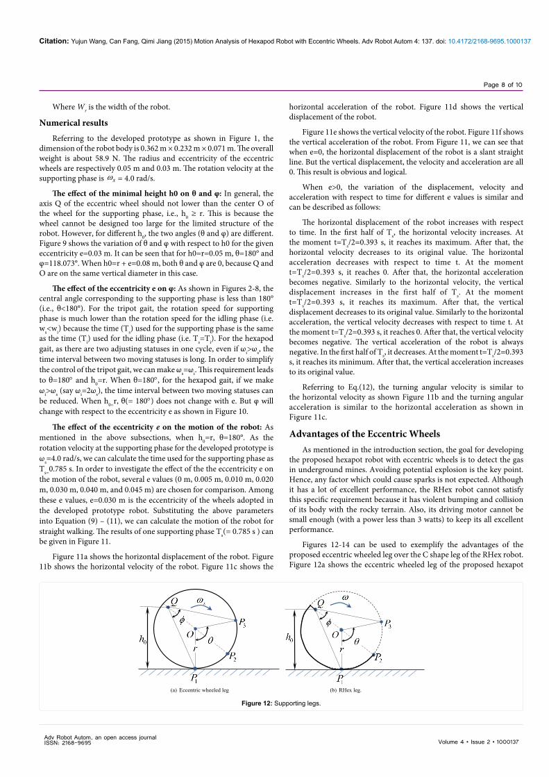
a. Horizontal displacement b. Horizontal velocity
c. Horizontal acceleration d. Vertical displacement
e. Vertical velocity f. Vertical acceleration
Figure 11: Displacement, velocity and acceleration vs time t for different e values.
Adv Robot Autom, an open access journal ISSN: 2168-9695
Citation: Yujun Wang, Can Fang, Qimi Jiang (2015) Motion Analysis of Hexapod Robot with Eccentric Wheels. Adv Robot Autom 4: 137. doi: 10.4172/2168-9695.1000137
Page 8 of 10
Volume 4 • Issue 2 • 1000137
Where Wr is the width of the robot.
Numerical results
Referring to the developed prototype as shown in Figure 1, the dimension of the robot body is 0.362 m × 0.232 m × 0.071 m. The overall weight is about 58.9 N. The radius and eccentricity of the eccentric wheels are respectively 0.05 m and 0.03 m. The rotation velocity at the supporting phase is ωs = 4.0 rad/s.
The effect of the minimal height h0 on θ and φ: In general, the axis Q of the eccentric wheel should not lower than the center O of the wheel for the supporting phase, i.e., h0 ≥ r. This is because the wheel cannot be designed too large for the limited structure of the robot. However, for different h0, the two angles (θ and φ) are different. Figure 9 shows the variation of θ and φ with respect to h0 for the given eccentricity e=0.03 m. It can be seen that for h0=r=0.05 m, θ=180° and φ=118.073°. When h0=r + e=0.08 m, both θ and φ are 0, because Q and O are on the same vertical diameter in this case.
The effect of the eccentricity e on φ: As shown in Figures 2-8, the central angle corresponding to the supporting phase is less than 180° (i.e., θ<180°). For the tripot gait, the rotation speed for supporting phase is much lower than the rotation speed for the idling phase (i.e. ws<wi) because the time (Ts) used for the supporting phase is the same as the time (Ti) used for the idling phase (i.e. Ts=Ti). For the hexapod gait, as there are two adjusting statuses in one cycle, even if ωi>ωs, the time interval between two moving statuses is long. In order to simplify the control of the tripot gait, we can make ωs=ωi. This requirement leads to θ=180° and h0=r. When θ=180°, for the hexapod gait, if we make ωi>ωs (say ωi=2ωs), the time interval between two moving statuses can be reduced. When h0=r, θ(= 180°) does not change with e. But φ will change with respect to the eccentricity e as shown in Figure 10.
The effect of the eccentricity e on the motion of the robot: As mentioned in the above subsections, when h0=r, θ=180°. As the rotation velocity at the supporting phase for the developed prototype is ωs=4.0 rad/s, we can calculate the time used for the supporting phase as Ts=0.785 s. In order to investigate the effect of the the eccentricity e on the motion of the robot, several e values (0 m, 0.005 m, 0.010 m, 0.020 m, 0.030 m, 0.040 m, and 0.045 m) are chosen for comparison. Among these e values, e=0.030 m is the eccentricity of the wheels adopted in the developed prototype robot. Substituting the above parameters into Equation (9) – (11), we can calculate the motion of the robot for straight walking. The results of one supporting phase Ts(= 0.785 s ) can be given in Figure 11.
Figure 11a shows the horizontal displacement of the robot. Figure 11b shows the horizontal velocity of the robot. Figure 11c shows the
horizontal acceleration of the robot. Figure 11d shows the vertical displacement of the robot.
Figure 11e shows the vertical velocity of the robot. Figure 11f shows the vertical acceleration of the robot. From Figure 11, we can see that when e=0, the horizontal displacement of the robot is a slant straight line. But the vertical displacement, the velocity and acceleration are all 0. This result is obvious and logical.
When e>0, the variation of the displacement, velocity andacceleration with respect to time for different e values is similar and can be described as follows:
The horizontal displacement of the robot increases with respect to time. In the first half of Ts, the horizontal velocity increases. At the moment t=Ts/2=0.393 s, it reaches its maximum. After that, the horizontal velocity decreases to its original value. The horizontal acceleration decreases with respect to time t. At the moment t=Ts/2=0.393 s, it reaches 0. After that, the horizontal acceleration becomes negative. Similarly to the horizontal velocity, the vertical displacement increases in the first half of Ts. At the moment t=Ts/2=0.393 s, it reaches its maximum. After that, the vertical displacement decreases to its original value. Similarly to the horizontal acceleration, the vertical velocity decreases with respect to time t. At the moment t=Ts/2=0.393 s, it reaches 0. After that, the vertical velocity becomes negative. The vertical acceleration of the robot is always negative. In the first half of Ts, it decreases. At the moment t=Ts/2=0.393 s, it reaches its minimum. After that, the vertical acceleration increases to its original value.
Referring to Eq.(12), the turning angular velocity is similar to the horizontal velocity as shown Figure 11b and the turning angular acceleration is similar to the horizontal acceleration as shown in Figure 11c.
Advantages of the Eccentric WheelsAs mentioned in the introduction section, the goal for developing
the proposed hexapot robot with eccentric wheels is to detect the gas in underground mines. Avoiding potential explosion is the key point. Hence, any factor which could cause sparks is not expected. Although it has a lot of excellent performance, the RHex robot cannot satisfy this specific requirement because it has violent bumping and collision of its body with the rocky terrain. Also, its driving motor cannot be small enough (with a power less than 3 watts) to keep its all excellent performance.
Figures 12-14 can be used to exemplify the advantages of the proposed eccentric wheeled leg over the C shape leg of the RHex robot. Figure 12a shows the eccentric wheeled leg of the proposed hexapot
(a) Eccentric wheeled leg (b) RHex leg.
Figure 12: Supporting legs.
Adv Robot Autom, an open access journal ISSN: 2168-9695
Citation: Yujun Wang, Can Fang, Qimi Jiang (2015) Motion Analysis of Hexapod Robot with Eccentric Wheels. Adv Robot Autom 4: 137. doi: 10.4172/2168-9695.1000137
Page 9 of 10
Volume 4 • Issue 2 • 1000137
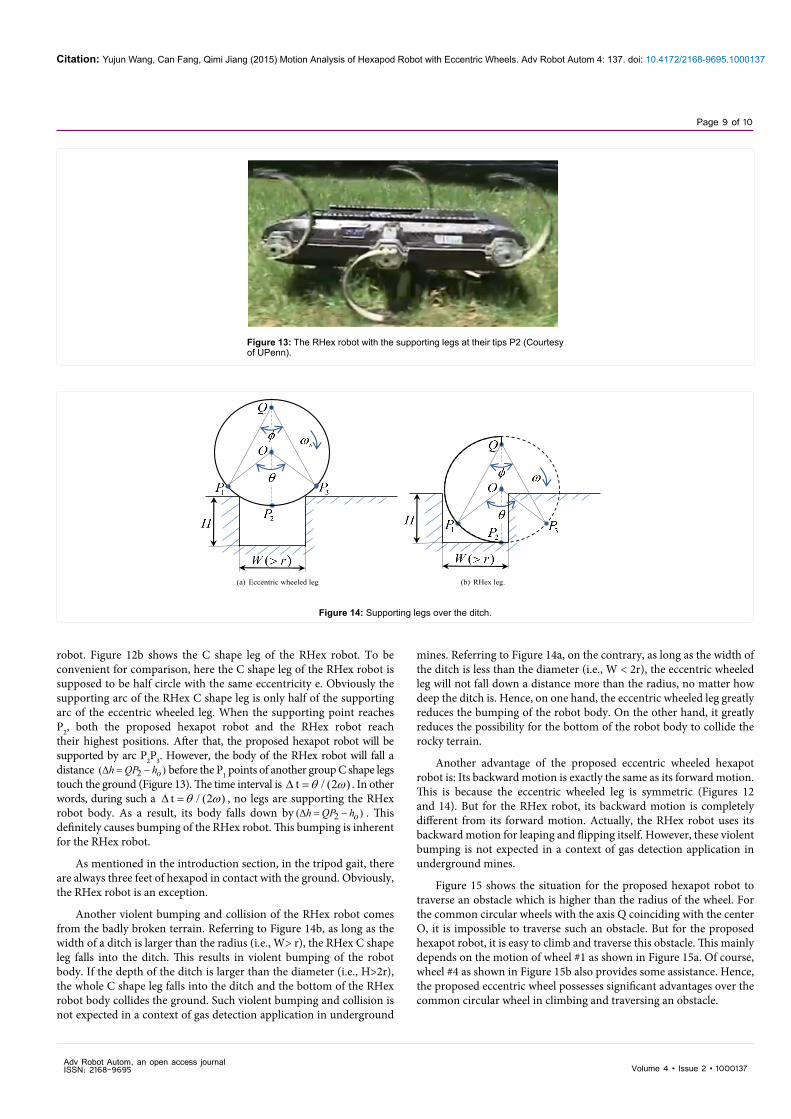
robot. Figure 12b shows the C shape leg of the RHex robot. To be convenient for comparison, here the C shape leg of the RHex robot is supposed to be half circle with the same eccentricity e. Obviously the supporting arc of the RHex C shape leg is only half of the supporting arc of the eccentric wheeled leg. When the supporting point reaches P2, both the proposed hexapot robot and the RHex robot reach their highest positions. After that, the proposed hexapot robot will be supported by arc P2P3. However, the body of the RHex robot will fall a distance 2( )∆ = − oh QP h before the P1 points of another group C shape legs touch the ground (Figure 13). The time interval is t / (2 )θ ω∆ = . In other words, during such a t / (2 )θ ω∆ = , no legs are supporting the RHex robot body. As a result, its body falls down by 2( )∆ = − oh QP h . This definitely causes bumping of the RHex robot. This bumping is inherent for the RHex robot.
As mentioned in the introduction section, in the tripod gait, there are always three feet of hexapod in contact with the ground. Obviously, the RHex robot is an exception.
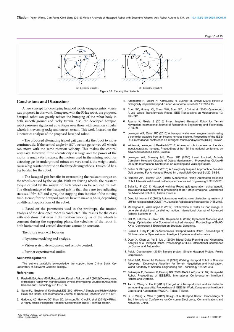
Another violent bumping and collision of the RHex robot comes from the badly broken terrain. Referring to Figure 14b, as long as the width of a ditch is larger than the radius (i.e., W> r), the RHex C shape leg falls into the ditch. This results in violent bumping of the robot body. If the depth of the ditch is larger than the diameter (i.e., H>2r), the whole C shape leg falls into the ditch and the bottom of the RHex robot body collides the ground. Such violent bumping and collision is not expected in a context of gas detection application in underground
mines. Referring to Figure 14a, on the contrary, as long as the width of the ditch is less than the diameter (i.e., W < 2r), the eccentric wheeled leg will not fall down a distance more than the radius, no matter how deep the ditch is. Hence, on one hand, the eccentric wheeled leg greatly reduces the bumping of the robot body. On the other hand, it greatly reduces the possibility for the bottom of the robot body to collide the rocky terrain.
Another advantage of the proposed eccentric wheeled hexapot robot is: Its backward motion is exactly the same as its forward motion. This is because the eccentric wheeled leg is symmetric (Figures 12 and 14). But for the RHex robot, its backward motion is completely different from its forward motion. Actually, the RHex robot uses its backward motion for leaping and flipping itself. However, these violent bumping is not expected in a context of gas detection application in underground mines.
Figure 15 shows the situation for the proposed hexapot robot to traverse an obstacle which is higher than the radius of the wheel. For the common circular wheels with the axis Q coinciding with the center O, it is impossible to traverse such an obstacle. But for the proposed hexapot robot, it is easy to climb and traverse this obstacle. This mainly depends on the motion of wheel #1 as shown in Figure 15a. Of course, wheel #4 as shown in Figure 15b also provides some assistance. Hence, the proposed eccentric wheel possesses significant advantages over the common circular wheel in climbing and traversing an obstacle.
Figure 13: The RHex robot with the supporting legs at their tips P2 (Courtesy of UPenn).
(a) Eccentric wheeled leg (b) RHex leg.
Figure 14: Supporting legs over the ditch.
Adv Robot Autom, an open access journal ISSN: 2168-9695
Citation: Yujun Wang, Can Fang, Qimi Jiang (2015) Motion Analysis of Hexapod Robot with Eccentric Wheels. Adv Robot Autom 4: 137. doi: 10.4172/2168-9695.1000137
Page 10 of 10
Volume 4 • Issue 2 • 1000137
Conclusions and DiscussionsA new concept for developing hexapod robots using eccentric wheels
was proposed in this work. Compared with the RHex robot, the proposed hexapod robot can greatly reduce the bumping of the robot body in both smooth ground and rocky terrain. Also, the developed hexapod robot possesses significant advantages over those with common circular wheels in traversing rocky and uneven terrain. This work focused on the kinematics analysis of the proposed hexapod robot.
• The proposed alternating tripod gait can make the robot to movecontinuously. If the central angle θ=180°, we can get ωs=ωi. All wheels can move with the same rotation velocity. This makes the control very easy. However, if the eccentricity e is large and the power of the motor is small (For instance, the motors used in the mining robot for detecting gas in underground mines are very small), the weight could cause a big resistant torque on the three driving wheels. This could be a big burden for the robot.
• The hexapod gait benefits in overcoming the resistant torque onthe wheels caused by the weight. With six driving wheels, the resistant torque caused by the weight on each wheel can be reduced by half. The disadvantage of the hexapod gait is that there are two adjusting statuses. If θ=180° and ωs=ωi, the stopping time is twice of the moving time. Hence, for the hexapod gait, we have to make ωi >> ωs depending on different applications of the robot.
• Based on the parameters used in the prototype, the motionanalysis of the developed robot is conducted. The results for the cases with e>0 show that even if the rotation velocity ωs of the wheels is constant during the supporting phase, the velocities of the robot in both horizontal and vertical directions cannot be constant.
The future work will focus on
• Dynamic modeling and analysis.
• Vision system development and remote control.
• Further experimental studies.
Acknowledgements
The authors gratefully acknowledge the support from China State Key Laboratory of Silkworm Genome Biology.
References
1. Rashid MZA, Aras MSM, Radzak AA, Kassim AM, Jamali A (2012) Development of Hexapod Robot with Manoeuvrable Wheel. International Journal of Advanced Science and Technology 49: 119-135.
2. Saranli U, Buehler M, Koditschek DE (2001) RHex: A Simple and Highly Mobile Hexa-pod Robot. The International Journal of Robotics Research 20: 616-631.
3. Galloway KC, Haynes GC, IIhan BD, Johnson AM, Knopf R, et al. (2010) X-RHex: A Highly Mobile Hexapedal Robot for Sensorimotor Tasks, Technical Report.
(a) Eccentric wheel #1 (b) Eccentric wheel #4Figure 15: Passing the obstacle.
4. Altendorfer R, Moore N, Komsuoglu H, Buehler M, Brown (2001) RHex: Abiologically inspired hexapod runner. Autonomous Robots 11: 207-213.
5. Chen SC, Huang KJ, Chen WH, Shen SY, Li CH, et al. (2013) Quattroped:A Leg–Wheel Transformable Robot. IEEE Transactions on Mechatronics 19:730-742.
6. Aparna K, Geeta S (2013) Insect Inspired Hexapod Robot for TerrainNavigation. International Journal of Research in Engineering and Technology2: 63-69.
7. Lewinger WA, Quinn RD (2010) A hexapod walks over irregular terrain usinga controller adapted from an insects nervous system. Proceeding of the IEEE/RSJ international conference on intelligent robots and systems(IROS), Taiwan.
8. William A, Lewinger H, Reekie M (2011) A hexapod robot modeled on the stick insect, carausius morosus. Proceedings of the 15th international conference on advanced robotics,Tallinn, Estonia.
9. Lewinger WA, Branicky MS, Quinn RD (2005) Insect Inspired, ActivelyCompliant Hexapod Capable of Object Manipulation. Proceedings CLAWAR2005 8th International Conference on Climbing and Walking Robots.
10. Belter D, Skrzypczynski P (2010) A Biologically Inspired Approach to FeasibleGait Learning For A Hexapod Robot. Int J Appl Math Comput Sci 20: 69-84.
11. Ramesh AP, Kumar CSK (2010) Autonomous Home Automated HexapodRobot. International Journal on Computer Science and Engineering 2: 3016-3020.
12. Seljanko F (2011) Hexapod walking Robot gait generation using geneticgravitational hybrid algorithm. proceeding of the 15th International Conference on Advanced Robotics, Tallinn, Estonia.
13. Daud M, Nonami K (2012) Autonomous walking over obstacles by means ofLRF for hexapod robot COMET-IV. Journal of Robotics and Mechatronics 2455-2463.
14. Mehdigholi H, Akbarnejad S (2012) Optimization of watts six bar linkage togenerate straight and parallel leg motion. International Journal of AdvancedRobotic Systems 9: 1-6.
15. Cal M, Fatuzzo G, Oliveri SM, Sequenzia G (2007) Dynamical Modeling AndDesign Optimization of A Cockroach-Inspired Hexapod. Proceedings of IMAC-XXV: Conference & Exposition on Structural Dynamics.
16. Burkus E, Odry P (2007) Autonomous Hexapod Walker Robot. Proceedings of 5th International Symposium on Intelligent Systems and Informatics.
17. Duan X, Chen W, Yu S, Liu J (2009) Tripod Gaits Planning and KinematicsAnalysis of a Hexapod Robot. Proceedings of IEEE International Conferenceon Control and Automation.
18. Polulu Coorporation (2010) Sample project: Simple Hexapod Project. PololuCorporation.
19. Billah MM, Ahmed M, Farhana S (2008) Walking Hexapod Robot in DisasterRecovery: Developing Algorithm for Terrain Negotiation and Navi-gation.World Academy of Science, Engineering and Technology 18: 328-333.
20. Birkmeyer P, Peterson K, Fearing RS (2009) DASH: A Dynamic 16g Hexapedal Robot. Proceedings of IEEE/RSJ International Conference on IntelligentRobots and Systems.
21. Tan X, Wang Y, He X (2011) The gait of a hexapod robot and its obstacle-surmounting capability. Proceedings of IEEE 9th World Congress on Intelligent Control and Automation (WCICA), Taipei, Taiwan.
22. Li J, Wang Y, Wan T (2012) Design of A Hexapod Robot. Proceedings of2nd International Conference on Consumer Electronics, Communications and Networks, China.
Adv Robot Autom, an open access journal ISSN: 2168-9695