Advances in ladle metallurgy control · Ladle Metallurgy Stations (LMS) play a crucial role in...
13
Advances in ladle metallurgy control Dr. Geoffrey Brooks and Dr. Subagyo McMaster Steel Research Center Department oj Materials Science and Engineering McMaster University 1280 Main St. West Hamilton, Ontario, Canada i8S 4L7 [email protected] ABSTRACT 41 Ladle Metallurgy Stations (LMS) play a crucial role in ensuring the quality of steel products. There is significant understanding of key aspects of both the chemistry and physics of the ladle process but this understanding has not translated into the development of sophisticated control systems. In general, the control of LMS is dominated by manual procedures that emphasize process stability over process optimization. This, in part, reflects the lack of suitable sensors but also a failure to produce a holistic control strategy for ladle metallurgy. There have been some significant developments in sensors and wider application of these new techniques is still being evaluated by the industry. Future work in LMS control should emphasize both sensor development and new control strategies that include the ability to optimize the process. Ladle and Tundish, COM 2002 Edited by K.C. Coley and G. Brooks
Transcript of Advances in ladle metallurgy control · Ladle Metallurgy Stations (LMS) play a crucial role in...

Advances in ladle metallurgy control
Dr. Geoffrey Brooks and Dr. Subagyo McMaster Steel Research Center Department oj Materials Science and Engineering McMaster University 1280 Main St. West Hamilton, Ontario, Canada i8S 4L7 [email protected]
ABSTRACT
41
Ladle Metallurgy Stations (LMS) play a crucial role in ensuring the quality of steel products. There is significant understanding of key aspects of both the chemistry and physics of the ladle process but this understanding has not translated into the development of sophisticated control systems. In general, the control of LMS is dominated by manual procedures that emphasize process stability over process optimization. This, in part, reflects the lack of suitable sensors but also a failure to produce a holistic control strategy for ladle metallurgy. There have been some significant developments in sensors and wider application of these new techniques is still being evaluated by the industry. Future work in LMS control should emphasize both sensor development and new control strategies that include the ability to optimize the process.
Ladle and Tundish, COM 2002 Edited by K.C. Coley and G. Brooks

42 LADLE AND TUNDlSH METALLlJRGY
INTRODUCTION
Ladle MetaJlurgy Stations (LMS) playa crucial role in ensuring the quality of steel products. There has been much research into fundamental aspects of ladle metallurgy by Fruchan, Guthrie, McLean, Irons and others, and there is significant understanding of key aspects of both the chemistry and physics of the ladle process. Unfortunately, this understanding has not translated into the development of sophisticated control systems and industrial practice is still largely dominated by manual control. In general, manual control of an LMS emphasizes process stability rather than process optimization. That is, the operator is more concerned with ensuring that steel reliably leaves the LMS within certain set points, than he or she is concerned with minimizing the qU'antity of reagents or stirring to achieve these set points. In this paper, we shall firstly address the cutTent technology, recent developments and finally propose future directions in this field.
The precise role of an LMS in a modem steel plant varies depending on the plant configuration and product range of the plant but we can identify three parameters that must be controlled to ensure high product quality from an LMS:
• temperature - homogeneity and final value,
chemistry - homogeneity and final levels ofC, S, P, 0, N, Ca, Si, Mn, A( and other alloy elements,
• inclusions characteristics- number, size, morphology and chemistry.
In a modem LMS, control of these key parameters is achieved througb manipulation of three main variables: (i) addition of reagents and fluxes, (ij) heating through electrodes mounted in the roofofthe LMS and (iii) stirring of the vessel through either injection of gas thi-ough a porous plug(s) at the bottom and/or a lance from the top of the vessel. In general, four other variables are "given" (i.e. the operator can not manipulate readily), the incoming steel chemistry, the incoming steel temperature, the quantity of carry over slag and its chemistry.
Our consideration offuture developments and potential methods for manipulating these key parameters to achieve not only stable but optimized ladle operation must begin with an overview of existing control practice.

LADLE AND TUNDISH METALLURGY 43
CURRENT CONTROL PRACTICE
Temperature
Temperature is an important control parameter and it critical to ensure that the steel leaves the LMS at an appropriate temperature. For this reason, "spot" temperature measurements are commonly taken several times during a heat. Spot measurements of temperature are made with thennocouple probes. These measurements can be carried out manually or automatically, depending on individual plant practices, though simultaneous measurement of temperature and oxygen content of the steel via an automatic "probe" or "drop in sensor" system is not tmcommon. These devices typically have an error of +/- 5 C associated with them and a response time of 10ms (1).
Continuous monitoring of temperature in the ladle wall through the installation of thennocouples into the refractory has been carried out by some steel companies but.provides only an indirect measure of bath temperature (2). These devices are also prone to damage and the signal can be easily "distorted" by the build up of solid material on the wall (which in itself maybe a useful piece of infonnation). MEFOS reported that mounting thennocouples some 20 to 40 mm from the liquid steel and than calibrating this signal against spot measurements allows an accurate continuous signal to be maintained (l).
Some continuous monitoring techniques have been proposed and tested in the steel industry including infrared pyrometry, radiation spectrometry (3), resistance thermometers and heat flow meters (1). Infrared pyrometry has gained some acceptance in the industry but is more easily applied to rolling and coating operations where the geometry, surface conditions and emissivity may be more easily defined than for hot liquid systems such as steelmaking and where problems of dust and severe heat add to the difficulties.
A number of commercial computer models have been developed to predict temperature loss in the ladle based on heat transfer considerations, initial steel te~perature, carry over slag depth and other pertinent variables (1). These models are normally used as part of an operator guidance system and do not generally contain any feedback parameters from the process. .
Chemical Composition
Metal composition values for C, S, P, 0, N, Ca, Si, Mn, Al and various alloying agents are commonly detennined for initial, intennediate and final stages of the heat. Samples are taken either through an automatic or manual inunersion probe system and generally analyzed using optical emission spectrometry (OES). It is possible to provide an analysis in less than five minutes from sampling (1). Accurate value of carbon levels, sulphur, oxygen and nitrogen are commoruy determined using destructive distillation techniques (LECO). LECO analysis is generally slower than OES but is required for accurate
44 LADLE AND TUN DISH \1ETALLURGY
control of final meta] chemistry. Oxygen acti vity in the steel is corrunonly measured using a separate probe. These probes are generally based on a Zirconia electrochemical cell which produces an EMF when immersed in the steel. Response times depend on oxygen concentration in the steel but are commonly less than 10 s.(1,6)
Recently, Drop in Sensor Systems (DIS) have been developed for BOFs that use a thermocouple-based liquidus arrest carbon prediction technology to measure carbon levels in the vessel in less in ten seconds after the sensor has been dropped into the melt (6). Continuous analysis techrUques [Of metal have also been proposed including sparking of the iron bath with direct analysis of spectra via optical fibre and atomizing of the surface to generate particles for analysis via a plasma burner and spectrum analyser (1). These techniques have yet to be commercialized in the steel industry.
Initial and final slag compositions are commonly sampled manually from the furnace and analyzed in a laboratory using X-ray Flouresence (XRF) or Inductively Coupled Plasma (rep) teclmiques. Results from XRF and rep commonly take hours to achieve. On line XRF analysis is not uncommon in the minerals industry, where less severe operating conditions are generally encountered, but the authors are not aware of this approach being used in the steel industry. Recently, slag oxygen activity sensors have become available that trap a quantity of slag from the melt in the tip of the senSOI, re-melt the sample and then use a zirconia cell to measure oxygen activity (6). This value is used to predict the FeO composition of the slag, a critical parameter in tight compositional control of certain grades of steel.
Inclusion Characteristics
The control of inclusion number, size, morphology and chemistry is one of the major aims of ladle metallurgy. In general, these parameters are not directly measured from heat to heat. Microscopic examination of different grades of steel leaving the plant are used to assess the success or otherwise of the calclum treatment and stining regime at lhe LMS through inclusion counting and sizing. Optical Microscopes (OM), Electron Microprobes (EMF) and Scanning Electron Microscopes (SEM) with Energy Dispersive Spectrometry (EDS) are used to assess the chemistry of the inclusions 1n the steel. This degree of examination is not a regular activity at most steel plants, in part, due to the expense associated with these various techniques. Often process parameters at the LMS are only examined if the particular grade of steel is found to be out of specified requirements. Automated image analysis systems have greatly improved the ability of companies to gather data on inclusion characteristics but it is not apparent that this is being used to assess the operation of LMS.
A new OES technique has been developed that allows analysis of total oxygen content (sum of total oxide inclusions), inclusion size distribution and inclusion composition to be determined in less than 10 minutes (7). Ultrasonic techniques have also been used to detect particle size and distribution in a sample of liquid steel (8). Doutre and Guthrie (6)

LADLE AND TUNDlSH METALLURGY 45
have developed an insitu technique for detecting inclusion size distribution and number through measuring the disturbance to an electric field caused by inclusions flowing through an orifice. All of these new approaches to inclusion characterization are promising but have not as yet been widely accepted or tested by the steel industry.
Stirring Energy
Stirring energy applied into the ladle is generally manipulated through manual control of gas flow rate into the stirring element on the ladle. Gas flow rate into the element is commonly controlled via a PLC signal to a control valve with a differential pressure flow meter used as a feedback signal to the controller. Operators generally set flow rates during a heat based on experience and visual observation of the "eye" region. The issue is complicated by the fact that it is common for gas supplied to a porous plug to not be fully utilized in the ladle because ofleaks and problems with installation (4).
Vibration detectors have been used to detennine the degree of stirring in a ladle (1,4,5). Stelco and Nupro Corporation have used vibration sensors on the walls 6f ladles as a basis for ladle control systems. Signals from an accelerometer mounted on the lid in the case of Stelco and sidewall sensor arm in the case of Nupro, are filtered and analyzed to detect frequencies relevant to gas stirring. The relevant characteristics of the signal have been reported to change with time, possibly due to refractory wear, and there is clearly some skill required in interpreting the signals from the instrument (4). Both Stelco and Nupro have reported positive results using vibration analysis to control gas flow into the ladle (4,5). It has also been suggested that vibration analysis can be used to detect changes in chemistry, notably sulphur and phosphorus (1). Vibration detectors clearly have some potential as a method of measuring stirring intensity in aLMS.
Slag and Metal Height
The height of slag and metal in the furnace is of importance to LMS operation, particularly in terms of controlling metal chemistry (N and 0 pick up), eye size, heat loss and heating characteristics of electric arc heating systems .. Another important variable at the start of a heat is knowing the amount of slag carry over from the previous process step (Oxygen Steelmaking or EAF)'. The problem of slag depth is made more complex because slag thickness varies across the vessel depending on operating conditions. In many plants, slag thickness is measured using a steel rod. The steel rod is immersed into the ladle until a portion has melted, this point is judged to be the depth ofthe slag/metal interface (11).
One approach to this problem developed by LTV steel is too utilize oxygen probes to detect the slag/air and slag/metal interface and thus calculate the height of each phase (9). Another technique developed for use at Rouge Steel relies on disturbance of an electromagnetic field by slag and metal to detect slag thickness (10). Nupro have developed a non-contact microwave based system that they claim accurately measures slag thickness across the diameter of the ladle and has a response time of between 30 to 45 seconds. This

46 LADLE AND TUNOlSI-I METALLURGY
new system has been successfully tested by U.S. Steel Corp. (11).
CONTROL STRATEGIES
The control ofthese key parameters in an LMS is achieved through manipulation of three main variables: (i) addition of reagents and fluxes, (ii) heating through electrodes mounted in the roof ofthe LMS and (iii) stirring ofthe vessel through either injection of gas through a porous plug(s) at the bottom and/or a lance from the top of the vessel. These variables interact with each other to effect the control of the process. For example, if you operate with high stirring with the aim of achieving a high rate of de-sulphurization, you are likely to expose the steel to the air at the ladle "eye", which in turn will promote nitrogen and oxygen pick up by the steel. High oxygen pick up will, in tum, promote increased inclusions and also reduce the thennodynamic drive for sulphur removal. The effects could be countered by additions offluxes (i.e. de-sulphurization slags) and reagents (i.e. AI for deoxidation). High stirring would also promote higher rates of heat loss from the ladle, thus the heating rate would have to be adjusted to compensated for this shift in operation. Carry over slag would also be a ~ignificant variable in this particular scenario, for ex am p Ie, a large amount of slag will affect the size ofthe ladle eye and the follow on effects described above. Similarly, a high FeD level in the cany over slag will work against de-sulphurisation and promote high oxygen levels in the metal. This simple scenario illustrates some of the complexity associated with achieving control of a LMS and illustrates how difficult it is for an operator to both ensure process stability and consider optimization of the process.
In many cases, the only variable that is really open for manipUlation is the stirring of the vessel through gas inj eetion. Generally, the addition of fluxes and additions follows quite rigid recipes that operators are reluctant to change. Similarly, the heating regime is largely set by the requirements of the casting process and is notnonnally an "independent" variable. As already mentioned, there is currently only limited control of the carry over slag in many shops, so this variable is also not easily manipulated. The next section will consider what is known about stirring in ladle in terms of affecting key control parameters.
INERT GAS STIRRING IN LADLES
Due to the importance of inert gas stirring in ladle, numerous studies have been carried out, including p tant measurements, physical modeling, and mathematical modeling, as recently summarized by Mazumdar and Guthrie (12). As far as inert gas stirred ladles are concerned and for the conditions as presented in Table I, the rate of mixing depends on the rate of energy input or energy dissipation and the geometry (size) of the vessel.

LADLE AND TUNDISJ-I METALLURGY
Table 1. Typical stirring conditions of ladle metallurgy steelmaking (12).
Parameter
Geometric ratio
Specific potential energy input,Wlt Kinematic viscosity, m2/s
0.5 ~ LJD $ 2.0
"'10.0 z: 10-6
47
The rate of energy input is defined in term of the rate of energy dissipation, e, using the following fonnula (13),
C=14.2QOTIOg(1+~pl (1) M 1.46 0
where f: is the rate ofenergy dissipation, watt/t, Qo is the volumetric gas flow rate, Nm3/min., T is bath temperature, K, M is liquid weight, t, H is depth of gas injection, m, and P () is the pressure at melt surface, bar.
Mixing time, 1, is defined as the time required for the monitoring point concentration to fall continuously within a Q pet deviation of a well mixedlhomogeneous value. The value n can be caJcuiated by the following equation:
C - C o = f x 100% (2)
C f - C i
where C j is initial concentration of the tracer, C f is final or homogeneous concentration of the tracer, and C is instantaneous concentration of the tracer. As reported by Mazumdar and Guthrie (12), the value of n ranges between 0.5 to 5%. Moreover, as shown in Figure 1, the pattern of instantaneous concentration as function of time is highly dependent on probe positions and tracer addition (14,15). The correlation the mixing time with the influenced variables is presented in Table IT.
Chemical Reaction and Inclusion Removal Rates
Desu!furization: The rate of desulfurization in an argon gas-stirring ladle can be calculated by the following correlation (16).
S - S log c =
So - Se - k t s (3)
Where ks is the rate constant, S is concentration of sulfur in steel, and subscripts (0) and Cc) indicate the initial and equilibrium conditions. The value of Se is function of

LADLE AND TUNDISH METALLURGY
temperature, slag composition, and oxygen activity (17). A recent industrial study of desulfurization by the authors has found tIus simple equation is not useful in situations where the chemistry of slag is changing with time (e.g. FeO is being reduced through reaction with At) because the thennodynamic drive for the removal of S is also changing with time. The authors are developing a new model to include this transient aspect of desulfurization and this will be the subject of a future paper.
2
1.6
...... 1.2 U ---U
0.8
0.4
o '. 0
I J I
\
[ill. *B •
~ I '-" . '- ' - _________ - ·_-·,------ --1
.. .'
20
.. « • -
...... ·A ... B
C
40 60 80
TiTre,s
100
Figure 1. Variation of instantaneous concentration for different probe position (14) .
Dephosphorization: The rate of phosphorus removal from the steel in an argon gas stining ladle is governed by a similar correlation with desulfurization (18). Similar to desulfurization, the equilibrium value of phosphorus concentration is function of temperature, slag composition, and oxygen activity (13).
Inclusion removal: The rate of inclusion removal from steel in an argon gas stirred ladle is represented by total oxygen content can be calculated using the following equation (18):
(4)
where ex is the time constant for inclusion removal, 0 is concentration of oxygen in steel, and subscripts CJ and (f) indicate the initial and final (after long stiffing times) conditions.
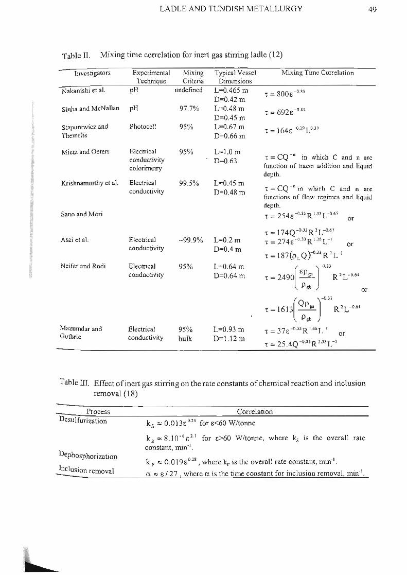
The effect of gas stirring on the rate constants of chemical reaction and non-metallic inclusion removal is sununarized in Table 3.
~.
LADLE AND TL~DISI-I METALLURGY 49
Table II. Mixing time correlation for inert gas stirring ladle (12)
Investigators
Nakanishi et a!.
Sinha and McNallan
Stapurewicz and Themclis
Experimental Technique
pH
pH
Photocell
Mixing Criteria
undefmed
97.7%
Typical Vessel Dimensions
L=0.465 m D::0.42 In
L·-::O.48 m D=0.45 In
L=0.67 m D=O.66 m
Mixing Time Correlation
Mietz and Oeters Electrical 95% 1..=1.0 m D=O.63 • = CQ -0 III which C and narc
flUlction of tracer addition and liquid depth.
conductivity colorimetry
Krishnamurthy d a1. Electrical 99.5% L=0.45 m D=0.48 m
"t = CQ -II in which C and n are functions of flow regimes and liquid depth.
Sana and Mori
Asai et al.
Neifcr and Rodi
Mazumdar and Guthrie
conductivity
Electrical conductivity
EJectncaJ conduclivity
Electrical conductivity
-99 .9%
95%
95% bulk
L=O.2m D=OA m
L=0.64 m D=0.64m
L=O.93 m D=1.12 m
t = 254£ -o.n R 1.33 r..- O.61
"[ = 174Q -0.J3 R 2 L-0.67
-. = 274E -o.33 Ri.36 L-1
or
or
"[ = 16l3( Q P b~l J-o
.
33
R 2 L - O.M
Pgb
t = 37E-o.l 3 R 1.661, I or "[ == 25 .4Q-O·3lR 1.331,-1
or
Table III. Effect of inert gas stining on the rate constants of chemical reaction and inclusion removal (18)
Process Desulfurization
Dephosphorization
Correlation
ks ::::; O.013~o.25 for E<60 W/tonne
ks R: 8 .10- 6 [.2.1 for 1:>60 W/tonne, where ks lS the overall rate constant, min· ' .
k p ~ 0.0 19E 028, where k[. is the overall rate constant, min';. Inclusion removal h . ~ . I . I 1 _____________________ -=a~~~E~/~2~7~,~w~h~e~r~e~~~is~·t~c_t~lm~e_c~o~n_s_ta_n_t_l_,o_r_ln_c __ u_s1_o_n_r_e_m_o_v_a~,_m_t_n-__

50 LADLE AND TC~DJSH METALLURGY
DISCUSSION
The typical LMS has only a few sensors associated with its operation. The sensors used are generally spot measurements taken at irregular intervals. This lack of sensory data in part explains the relative lack of automatic control systems associated With LMS. There have been some signjficant developments in sensors for severe applications and wider application of these new techniques is still being evaluated by the industry. Of particular relevance to ladle metallurgy are: vibration detectors for detecting stirring, advanced OES techniques for spot determinations of inclusion characterization, continuous inclusion characterization through either ultrasonics or electrical disturbance, and non-contact depth measurement systems.
rmproved sensors, combined with improved control logic, should allow LMS to be optimised. The main variable available for controlling the process is through inert gas stirring. Therefore, a proper stirring intensity should be achieved to get the optimum results. The best way to measure the result of mixing is based on analysing the batA condition, e.g. chemical composition of steel and slag by sampling analysis. However, this kind of data is not currently available. In tpis case, an inferential model- which 1S a model employing easily measured variables to predict the true variable - can be developed for designing a feedback controller (19).
For the purpose of designing a control strategy with a primary objective to achieve homogenization, the mixing time correlation proposed by Mazumdar and Guthrie (12) in Table II may be used as an inferential modeL A reasonably good agreement between predicted values from a large body of experimental data, as reported by these authors, is a reason of choosing this correlation. The equatlon may be rearranged to give
t = f\ (e, R, L) (Sa)
or
(5b)
Based on Equation (5), it is clear that the control objective is mixing time, 'C. Since the values of vessel radius, R, and vessel height, h, are fixed, gas flow rate, Q, or stirring power, e, is the manipUlative variable. Although, the value of Q can easily be read from a flow-rate instrument, the reading value may not be the true flow rate in the liquid bath due to the leakage in the supply system or in the plugs. Therefore, it may be worthwhile to consider stirring power, c, watt, that can be measured by monitoring ladle vibration as the manipulated variable (4,5).
However, if the main objective of inert gas stiffing is a combination between homogenization, acceleration of mass transfer and chemical reaction rate, and non-metallic inclusion removal, Equation (5) can not be directly taken as an inferential model. The control

-
t
LADLE AND TUNDISH METALLURGY 51
objective should be the temperature distribution and chemical composition. Since the realtime measurement for these data is not available, a multivariate inferential model is needed. What ever models are used, computing speed and accuracy are vital elements to be considered. To develop an appropriate model, a Partial Least Squares (PLS) method suggested by Kresta (19) may be used. Moreover, stirring power, £, or gas flow rate, Q, can be used as the manipUlative variable. This is approach and others are currently being investigated by the authors and will be the subject of future papers.
CONCL USIONS
In general, the control ofLMS is dominated by manual procedures that emphasizes process stability over process optimization. This, in part, reflects the lack of suitable sensors but also a failure to produce a holistic control strategy for ladle metallurgy. Future work in LMS control should emphasize both sensor development and new control strategies that include the ability to optimize the process.
ACKNOWLEDGEMENTS
The authors are grateful for the shared insights and discussions with Professor Irons, Professor McGregor, Professor Swartz, Professor Coley, Mr Rick Minion, Dr Stanley Sun, Mr Stephen Waterfall and Mr Sanjay Sagar.
REFERENCES
1. G. Carlsson, T. LeImer, M. Bnmner and T. Thoran, "Instrumentation for Ladle Metallurgical Control - Review", SCANlNJECT TV, Jernkontoret, Lulea Sweden, 1986,11 :1-37
2. A. Perkins, T. Robertson and D. Smith, "Improvements to Liquid Steel Temperature Control in the Ladle and Tundish", SCANINJECT N, J emkontoret, Lulea Sweden, 1986, 10: 1-29
3. K Chiba, A.Ono, M. Saeki, M. Yamauchi, M. Kanamoto and T. Ohno, "Development of direct analysis method for molten iron in converter - hotspot radiation spectrometry", Ironmaking and Steelmaking, 20.,3, 1993,215-220.
52 LADLE AND TUNDISJ-I METALLURGY
4. R.L. Minlon, C.F. Leckie, K.J. Legeard and B.D. Richardsson, '(Improved Ladle Stirring Using Vibration Technology at SteJco Hilton Works", ISM, July 1998, 25-31.
5. F.K. Kenneny, D.l. Walker and J.A.T. Jones, "Accurate Argon Stirring in the Ladle by Vibration Measurement", 2000 Electric Furnace Conference Proceedings, ISS, Warrendale Pa. USA, 2000, 723-733.
6. W.F. Nirschel, R.P . Stone and c.J.Carr, "Overview of Steelmaking Process Control Sensors for the BOF, Ladle and Continuous Casting Tundish", ISM, March 2001, 61-65.
7. M. Goransson, F . Reinholdson and K. Williams, "Evaluation of Liquid Steel Samples for the Detennination of Micro inclusion Characteristics by Spark-Induced Optical Emission Spectroscopy", ISM, May 1999, 53-58 .
8. N.D.G. Mountford, P. RahIm, S.Lee and I.D . Sonunerville, "Development of an Untrasonic Sensor for the Measurement of Liquid Steel Cleanliness", 1991 Steelmaking Conference Proceedings, ISS, Warrendale Pa. USA, 1991, 773 .
9. R. E. Kracich andK. Goodson, "Ladle Slag Depth Measurement", 1996 Steelmaking Conference Proceedings, ISS, Warrendale Pa. USA, 53-60.
10. G. Lee and K. Bertermann, "Implementation of a Slag Thickness Measurement Too l", 1996 S teelmakin g Conference Proceedin gs, IS S, Wanendale P a. USA, 61-65.
11. G.A. Meszaros, J. G. Estocin and R Marquart, E .L. Kemeny and D.I. Walker, ('Optimal Ladle Slag Conditioning Using U.S. Steels DepthWarc Noncontact Slag Measurement System", ISM, June 2000,31-34.
·L2. D. Mazumdar. and RI.L Guthrie, "Mixing Times and Correlations for Gas Stirred ladle Systems", ISS Trans .. ISM, 26(9), 1999, 89-96.
13. J. Szekely, G. Carlsson and L. Helle, Ladle Metallurgv, Springer-Verlag, New York, 1988 ..
14. D. Mazumdar and R.I.L Guthrie, "Mixing Models for Gas Stirred Metallurgical Reactors", Metall. Trans., 1m, 1986, 725-733.
15. D. Mazumdar, H.B . Kim and RLL. Guthrie, "Modelling Criteria for Flow Simulation in Gas Stirred Ladles : Experimental Study", Ironmaking & Steelmaking, 27(4),2000,302-309.

LADLE AND TUN DISH METALLURGY 53
16. E.T. Turkdogan, "Technology Innovations in Pneumatic Steelmaking and Ladle-Refining Processes in the 1980's", SCANINJECT IV, Jemkontoret, Lulea, Sweden, 1986 ..
17. R.J. Fruehan, Ladle Metallurgy Principles and Practices, ISS-AIME, Warrendale, 1985.
18. G.J.W KOf and P.e. Glaws, "Ladle Refining and Vacuum Degassing", The Making. Shaping and Treating of Steel, Fruehan, R.J.(Eds.), The AlSE Steel Foundation, Pittsburgh, 1998 ..
19. lY. Kresta, The Application of Partial Least Squares to Problem in Chemical Engineering, PhD Thesis, McMaster University, Canada, 1992.