Advances in Breaker-Failure Protection
18
Advances in Breaker-Failure Protection Héctor J. Altuve, Michael J. Thompson, and Joe Mooney Schweitzer Engineering Laboratories, Inc. Presented at the 20th Power, Industrial Applications and Industrial Exhibition Summer Meeting Acapulco, Mexico July 8–14, 2007 Previously presented at the 61st Annual Georgia Tech Protective Relaying Conference, May 2007 Originally presented at the 33rd Annual Western Protective Relay Conference, October 2006
Transcript of Advances in Breaker-Failure Protection

Advances in Breaker-Failure Protection
Héctor J. Altuve, Michael J. Thompson, and Joe Mooney Schweitzer Engineering Laboratories, Inc.
Presented at the 20th Power, Industrial Applications and Industrial Exhibition Summer Meeting
Acapulco, Mexico July 8–14, 2007
Previously presented at the 61st Annual Georgia Tech Protective Relaying Conference, May 2007
Originally presented at the 33rd Annual Western Protective Relay Conference, October 2006

1
Advances in Breaker-Failure Protection Héctor J. Altuve, Michael J. Thompson, and Joe Mooney, Schweitzer Engineering Laboratories, Inc.
Abstract—In this paper we first review backup protection concepts and analyze the impact of breaker-failure protection on power system stability. We show the importance of having differ-ent breaker-failure operating times for different types of faults.
We then introduce breaker-failure schemes and also a scheme for breaker-flashover protection. We discuss the effect of fault-detector reset time and describe fast-reset instantaneous over-current elements. Next we discuss alternatives for initiating breaker-failure operation in protection schemes where different relays trip the same breaker for faults in different protection zones. We also review breaker-failure tripping practices.
Later we discuss the advantages of integrating bus and breaker-failure protection in the same digital relay for substa-tions with complex bus arrangements. We finally present an eco-nomical solution for breaker-failure protection in distribution substations.
Keywords: Local backup protection, breaker failure.
I. INTRODUCTION For many years, protection engineers have applied local
breaker-failure protection to high-voltage (HV) and extra-high-voltage (EHV) systems with electromechanical relays and solid-state relays. These breaker-failure schemes were designed within the limits of the prevailing technology, such as inaccurate timers with overtravel and slow-reset overcur-rent elements. The development of microprocessor-based re-laying, digital input filtering, and low-burden CT secondary circuits allows easier breaker-failure protection application with measurable gains in performance. This is the reason for revisiting breaker-failure protection in this paper.
II. BACKUP PROTECTION CONCEPTS Given the importance of power system protection and con-
sidering that a protection system may fail to operate, it is common to have two protection systems: primary and backup protection. This is particularly important for short-circuit pro-tection, because the short circuit is the most frequent type of system failure. Therefore, the probability for the primary short-circuit protection to fail is higher than that of the protec-tion against other abnormal operating conditions.
Primary protection is the first line of defense. Primary short-circuit protection operation should be as fast as possible, preferably instantaneous, for stability and power quality rea-sons, and to prevent equipment damage.
Increasing power system protection reliability requires a backup protection system to operate in case the primary pro-tection system fails. Failure of any one of the primary relaying system elements (protective relays, voltage and current trans-formers, circuit breakers, dc supply system, communications channel, and control cables) could be the cause of a primary protection failure to operate. It is necessary to design backup
protection so that anything that might cause a primary protec-tion failure will not also cause a backup protection failure. In other words, primary and backup protection should not have common-mode failures to operate, but must provide redundant protection, preferably dual-redundant protection.
Fig. 1 shows the one-line diagram of a power system and helps to illustrate the concept of backup protection. For this discussion, we refer to protection systems by the circuit breaker numbers, i.e. the protection at Breaker 1 is called Pro-tection 1. The bus-tie circuit breaker (T) at Bus C is assumed normally closed during normal operating conditions. For a fault at Line CD, Circuit Breakers 5 and 6 should operate as the primary protection. If Protection 5 fails to operate, there are two possibilities for removing the fault current contribu-tion from A, B, E, and F: open Circuit Breakers 1, 3, and 8, or open Circuit Breakers 2 and T. In any case, backup protection needs time delay. The primary protection needs to be given an opportunity to operate before the decision to perform a backup operation is made.
1 2 5 6 11 12
3 4 7 8 9 10
T
A
B
EDC
F
Breaker5 Fails
Fig. 1. Local and Remote Backup Protection Circuit Breakers 1, 3, and 8 are located at remote substa-
tions and provide remote backup protection for faults else-where in the power system (Fig. 1). A backup protection sys-tem typically serves as remote backup protection for more than one primary protection system. For example, Protection 1 is the remote backup protection for Lines BC and CD and Bus C. Then, the zone of remote backup protection starts at the backup relay location and extends in one direction to cover at least all adjacent system elements. For faults in the backup zone, remote backup must operate more slowly than the slow-est primary protection.
An advantage of remote backup protection is low cost: the remote backup protection comes from protection equipment that is needed for primary protection functions of adjacent system elements. This eliminates the need for additional in-vestment. Remote backup is widely used in distribution and subtransmission systems. However, as we will see later, op-erational drawbacks of remote backup protection limit its ap-plication in transmission systems.

2
Circuit Breakers 2 and T represent local backup protection, which is located in the same substation as the primary protec-tion (Fig. 1). Local backup protection used to be more expen-sive than remote backup because additional equipment was needed to duplicate some protection system elements. In many cases, with multifunction relays, local backup requires no ad-ditional equipment.
The advantages of local backup over remote backup are greater selectivity, greater sensitivity, and faster operation. For these reasons, local backup is widely used in modern power systems, which operate close to their stability limits.
Fig. 1 serves to illustrate the selectivity limitation of re-mote backup protection. By tripping Breakers 1, 3, and 8 when Protection 5 fails to operate, we interrupt tapped loads of unfaulted lines AC, BC, and CD. In addition, if the reason Protection 5 fails to operate is a primary relay failure, the sec-ond set of primary relays (if any) will operate to trip Breaker 5 (rather than Breakers 2 and T), keeping Substation C in ser-vice.
Remote backup also has sensitivity limitations. For exam-ple (see Fig. 1), Protection 1 needs to reach the remote ends of lines BC and CD to provide remote backup to these lines. This is difficult to achieve in cases of a strong infeed effect at Bus C, which requires a long-reaching protection zone. A distance relay with a very large Zone 3, for example, may mi-soperate because of load encroachment or power swings. We therefore need to set the relay with a shorter reach. For this relay to detect the fault, relays at other terminals will have to trip first, and reduce the infeed effect, thus increasing the backup relay reach. The result is a sequential tripping opera-tion of the protection system.
As mentioned before, a given protection system typically serves as remote backup for more than one primary protection. For faults in the backup zone, remote backup must operate more slowly than the slowest primary protection. Coordina-tion time intervals are typically no less than 200 ms. As a re-sult, backup protection is slow, with operating times typically greater than 300 ms. Typical distance protection third-zone setting times, for example, are around 800 ms to 1 s. Remote backup fault-clearing time is even higher with sequential trip-ping.
Local backup protection greatly simplifies the task of con-tingency analysis and long-term maintenance of protection coordination settings. Calculating remote backup protection settings requires careful analysis of all possible contingencies to ensure coverage of adjacent protection zones. Any changes in the power system require a complete coordination study. Local backup protection allows the design and setting of each protection system to protect its specific zone. This minimizes the need to consider coverage of adjacent zones and to convey frequent setting revisions [1].
Backup protection should operate independently of the primary protection system. For local backup this requires du-plicating all the components of the primary protection system equipment. In modern power systems the tendency is to dupli-cate all the components, except the breaker, which is the most expensive element of the protection system, at the transmis-
sion level. We may also find lower degrees of duplication in some cases.
Improving protection system reliability requires a func-tional duplication of the breaker. This is the role of breaker-failure protection, which identifies that the breaker failed to interrupt current after receiving a tripping signal, and operates with time delay to trip backup breakers.
III. IMPACT OF BREAKER-FAILURE PROTECTION ON POWER SYSTEM STABILITY
Breaker-failure tripping times can have a significant impact on system stability. A breaker-failure operation may result in additional line or equipment outages, as well as the increased duration of the fault. For the most part, the critical clearing time is determined from stability studies where a three-phase fault is applied at key locations on the system. A three-phase fault is considered the worst-case condition as power cannot be transferred through the faulted part of the power system and the result is a maximum change in the nearby machine angles. Three-phase faults do not happen very often, and es-tablishing a breaker-failure delay using these criteria usually results in short delays with little margin.
The following examples show that different fault types re-sult in different critical clearing times. It may be beneficial to increase the breaker-failure delay using other fault types to improve margin and the security of the scheme recognizing that three-phase faults are unlikely to occur.
The following waveforms and results are test cases from a system model [2] developed on a real-time digital simulator manufactured by RTDS Technologies. The system shown in the Appendix is used for these tests.
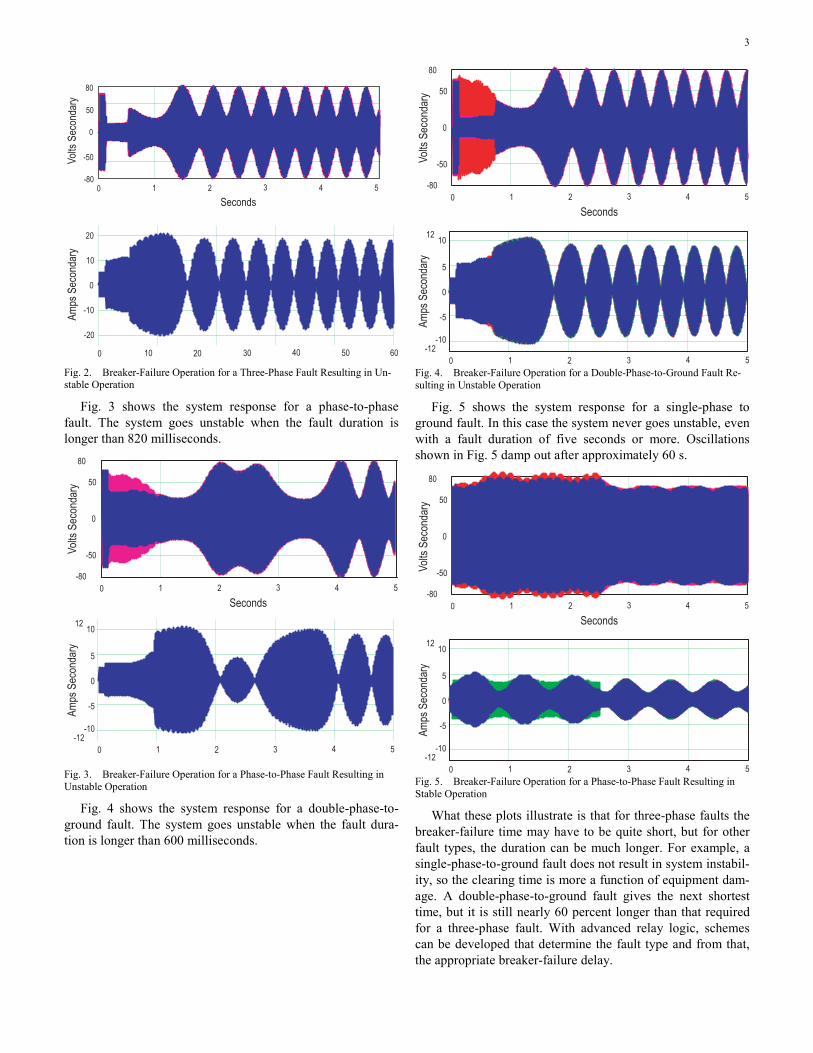
A fault is applied on one of the lines between Buses A and B (see Fig. 33). The voltage and current waveforms from the monitored line (Line 7) are shown for the terminal nearest the faulted line. At the faulted line, the terminal nearest the fault is where the breaker-failure operation occurs. The fault duration is varied to show where fault clearing results in an unstable system response. For all faults, the protection at the far termi-nal operated correctly.
Fig. 2 shows the system response for a three-phase fault. The system goes unstable when the fault duration is longer than 380 milliseconds.
3
80
50
0
-50
-800 1 2 3 4 5
Seconds
Vol
ts S
econ
dary
Am
ps S
econ
dary
20
10
0
-10
-20
0 10 20 30 40 50 60
Fig. 2. Breaker-Failure Operation for a Three-Phase Fault Resulting in Un-stable Operation
Fig. 3 shows the system response for a phase-to-phase fault. The system goes unstable when the fault duration is longer than 820 milliseconds.
80
50
0
-50
-80
0 1 2 3 4 5
Seconds
Vol
ts S
econ
dary
Am
ps S
econ
dary
12
5
0
-5
-12
0 1 2 3 4 5
10
-10
Fig. 3. Breaker-Failure Operation for a Phase-to-Phase Fault Resulting in Unstable Operation
Fig. 4 shows the system response for a double-phase-to-ground fault. The system goes unstable when the fault dura-tion is longer than 600 milliseconds.
80
50
0
-50
-80
0 1 2 3 4 5
Seconds
Vol
ts S
econ
dary
Am
ps S
econ
dary
12
5
0
-5
-12
0 1 2 3 4 5
10
-10
Fig. 4. Breaker-Failure Operation for a Double-Phase-to-Ground Fault Re-sulting in Unstable Operation
Fig. 5 shows the system response for a single-phase to ground fault. In this case the system never goes unstable, even with a fault duration of five seconds or more. Oscillations shown in Fig. 5 damp out after approximately 60 s.
80
50
0
-50
-80
0 1 2 3 4 5
Seconds
Vol
ts S
econ
dary
Am
ps S
econ
dary
12
5
0
-5
-12
0 1 2 3 4 5
10
-10
Fig. 5. Breaker-Failure Operation for a Phase-to-Phase Fault Resulting in Stable Operation
What these plots illustrate is that for three-phase faults the breaker-failure time may have to be quite short, but for other fault types, the duration can be much longer. For example, a single-phase-to-ground fault does not result in system instabil-ity, so the clearing time is more a function of equipment dam-age. A double-phase-to-ground fault gives the next shortest time, but it is still nearly 60 percent longer than that required for a three-phase fault. With advanced relay logic, schemes can be developed that determine the fault type and from that, the appropriate breaker-failure delay.
4
IV. BREAKER-FAILURE PROTECTION SCHEMES
A. General Considerations We may define a breaker failure as a failure of the breaker
to open contacts or to interrupt current after receiving a trip-ping signal. Therefore, we declare a breaker failure when two conditions are true:
• The primary relays tripped. • There is current flowing through the breaker.
To detect the current flowing through the breaker we use a set of phase and ground instantaneous overcurrent elements (50/50N). This is the common practice for transmission-line breaker-failure schemes. The phase elements must be set be-low the minimum fault current in the protected section. In heavily loaded lines this setting could be below the maximum load. In this case the scheme loses security, because the in-stantaneous overcurrent element will remain operated for heavy load conditions.
Transformer internal faults may not produce enough cur-rent to operate breaker-failure instantaneous overcurrent ele-ments. In this case, start the breaker-failure scheme using a contact of the transformer primary protective relay, supervised by a breaker normally-open auxiliary contact 52a (AND logic). Generators may also experience faults and other ab-normal operating conditions that will not produce high cur-rents. In generator breaker-failure schemes we use a 52a breaker auxiliary contact as another alternative to the 50 ele-ments (OR logic) [3]. It is important to notice that breaker auxiliary contacts 52a are not a very reliable indicator of the breaker status: when a breaker fails, its 52a contacts may be open, while the main contacts may be closed [4].
We need to apply one breaker-failure scheme per breaker in all bus configurations. Each scheme should trip and lock out all breakers in its zone. In most cases it is also necessary to trip at least one remote breaker to completely isolate the faulted section. We may also need to prevent remote breaker from reclosing. The breaker-failure scheme should make an attempt to retrip the failed breaker prior to tripping adjacent breakers. This improves security for cases in which the fault detector is set below the load current and the scheme receives a spurious initiate signal. In this case, the retrip logic trips only one breaker rather than tripping all the backup breakers.
When the failed breaker is isolated by disconnect switches or when we remove a breaker from service for maintenance or testing, the breaker-failure scheme should be disabled. This prevents inadvertent tripping of other breakers in service. It is
important to make sure that the breaker is isolated from the system before disabling the breaker-failure scheme. A warning message placed at the scheme disabling switch, for example, helps prevent maintenance personnel from opening the switch with the breaker in service.
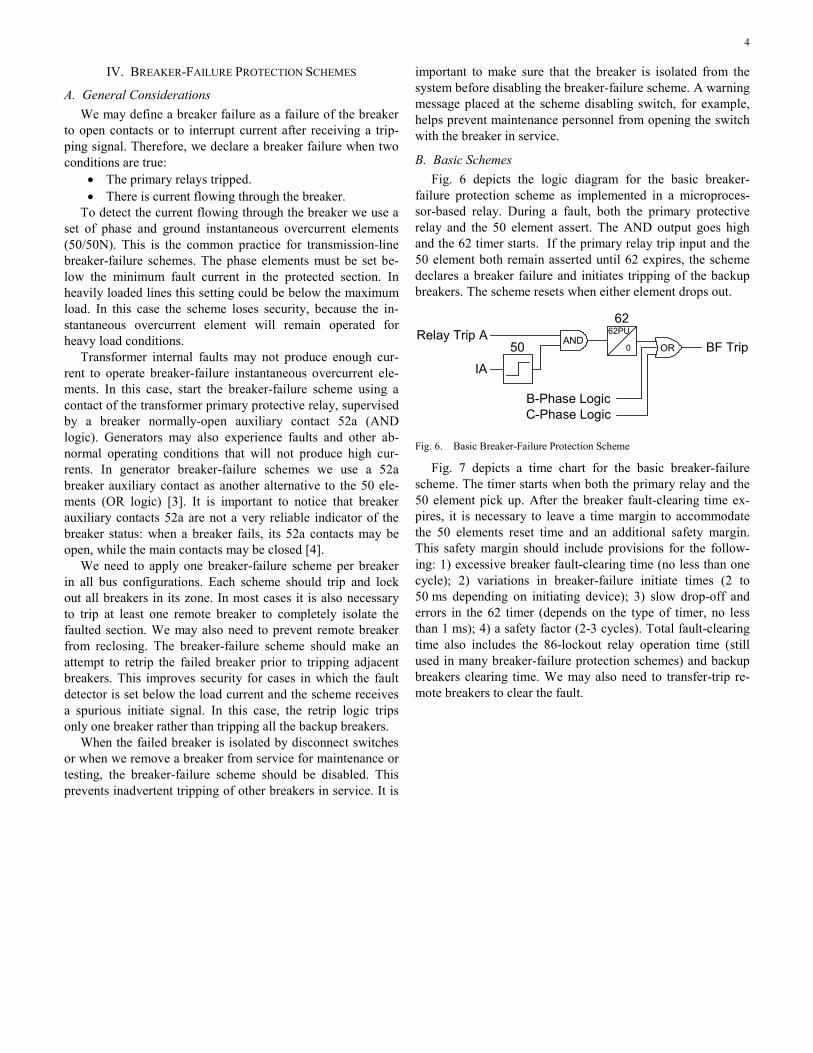
B. Basic Schemes Fig. 6 depicts the logic diagram for the basic breaker-
failure protection scheme as implemented in a microproces-sor-based relay. During a fault, both the primary protective relay and the 50 element assert. The AND output goes high and the 62 timer starts. If the primary relay trip input and the 50 element both remain asserted until 62 expires, the scheme declares a breaker failure and initiates tripping of the backup breakers. The scheme resets when either element drops out.
Relay Trip A
IA
50 AND
B-Phase LogicC-Phase Logic
BF Trip
6262PU
0 OR
Fig. 6. Basic Breaker-Failure Protection Scheme
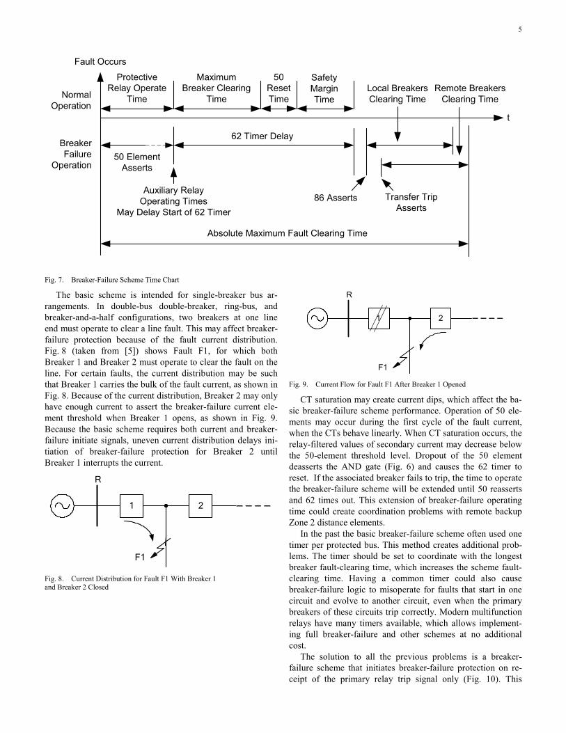
Fig. 7 depicts a time chart for the basic breaker-failure scheme. The timer starts when both the primary relay and the 50 element pick up. After the breaker fault-clearing time ex-pires, it is necessary to leave a time margin to accommodate the 50 elements reset time and an additional safety margin. This safety margin should include provisions for the follow-ing: 1) excessive breaker fault-clearing time (no less than one cycle); 2) variations in breaker-failure initiate times (2 to 50 ms depending on initiating device); 3) slow drop-off and errors in the 62 timer (depends on the type of timer, no less than 1 ms); 4) a safety factor (2-3 cycles). Total fault-clearing time also includes the 86-lockout relay operation time (still used in many breaker-failure protection schemes) and backup breakers clearing time. We may also need to transfer-trip re-mote breakers to clear the fault.
5
Fault Occurs
NormalOperation
Breaker Failure
Operation50 Element
Asserts
Protective Relay Operate
Time
Maximum Breaker Clearing
Time
50Reset Time
Safety Margin Time
Local BreakersClearing Time
Remote Breakers Clearing Time
t
62 Timer Delay
Auxiliary RelayOperating Times
May Delay Start of 62 Timer
Absolute Maximum Fault Clearing Time
86 Asserts Transfer Trip Asserts
Fig. 7. Breaker-Failure Scheme Time Chart
The basic scheme is intended for single-breaker bus ar-rangements. In double-bus double-breaker, ring-bus, and breaker-and-a-half configurations, two breakers at one line end must operate to clear a line fault. This may affect breaker-failure protection because of the fault current distribution. Fig. 8 (taken from [5]) shows Fault F1, for which both Breaker 1 and Breaker 2 must operate to clear the fault on the line. For certain faults, the current distribution may be such that Breaker 1 carries the bulk of the fault current, as shown in Fig. 8. Because of the current distribution, Breaker 2 may only have enough current to assert the breaker-failure current ele-ment threshold when Breaker 1 opens, as shown in Fig. 9. Because the basic scheme requires both current and breaker-failure initiate signals, uneven current distribution delays ini-tiation of breaker-failure protection for Breaker 2 until Breaker 1 interrupts the current.
1 2
R
F1
Fig. 8. Current Distribution for Fault F1 With Breaker 1 and Breaker 2 Closed
1 2
R
F1
Fig. 9. Current Flow for Fault F1 After Breaker 1 Opened
CT saturation may create current dips, which affect the ba-sic breaker-failure scheme performance. Operation of 50 ele-ments may occur during the first cycle of the fault current, when the CTs behave linearly. When CT saturation occurs, the relay-filtered values of secondary current may decrease below the 50-element threshold level. Dropout of the 50 element deasserts the AND gate (Fig. 6) and causes the 62 timer to reset. If the associated breaker fails to trip, the time to operate the breaker-failure scheme will be extended until 50 reasserts and 62 times out. This extension of breaker-failure operating time could create coordination problems with remote backup Zone 2 distance elements.
In the past the basic breaker-failure scheme often used one timer per protected bus. This method creates additional prob-lems. The timer should be set to coordinate with the longest breaker fault-clearing time, which increases the scheme fault-clearing time. Having a common timer could also cause breaker-failure logic to misoperate for faults that start in one circuit and evolve to another circuit, even when the primary breakers of these circuits trip correctly. Modern multifunction relays have many timers available, which allows implement-ing full breaker-failure and other schemes at no additional cost.
The solution to all the previous problems is a breaker-failure scheme that initiates breaker-failure protection on re-ceipt of the primary relay trip signal only (Fig. 10). This

6
scheme uses a separate timer for each breaker. We can use this scheme in single- and multi-breaker bus configurations, such as double-bus double-breaker, ring-bus, and breaker-and-a-half arrangements. When the trip input is asserted, the 62 pickup timer starts. If the 50 element is asserted when the 62 timer expires, the scheme declares a breaker failure. If the trip input is deasserted before 62 expires, the timer resets.
Relay Trip A
IA50
AND
B-Phase Logic ...
BF TripOR
62PU62
0
C-Phase Logic ...
Fig. 10. Using Only Primary Relay Trip Information to Start Timer Im-proves Breaker-Failure Scheme Performance
Referring to the time chart shown in Fig. 7, in this breaker-failure scheme the 62 timer is initiated by primary protective relay operation only. If the 50 element is asserted when the timer operates, the scheme declares a breaker failure. This logic is independent of anything the 50 element does during the timing interval, as long as it is present at the end of the interval. This accommodates possible 50 element delays caused by current redistribution in multi-breaker configura-tions. This scheme is relatively immune to dropout from CT saturation. CT saturation would have to be very severe to cause the 50 element to be de-asserted at the end of the 62 timing delay. For example, in an EHV application with two-cycle clearing and three-cycle margin, saturation would have to last longer than five cycles to affect the clearing time.
Fig. 11 depicts the functional schematic diagram of a scheme developed to improve the total clearing time during a breaker failure by eliminating the 50 element dropout time in the safety margin of the 62 timer setting [6]. This scheme is intended for use in single-breaker or multi-breaker installa-tions. When the relay trip input is asserted, the 62 pickup timer starts. After the 62 timer pickup time elapses, the 62 timer output asserts and closes the switch. The timer output remains asserted for a given time window. A breaker failure is declared if the 50 element picks up and asserts during the time window. This scheme was invented to eliminate any problems with slow reset of the fault detector in non-numerical relay designs. Supposedly, this scheme saves one-to-two cycles in clearing time. However, total clearing time should include the 50-element operating time in the overall safety factor. As a result, the difference in total clearing time values between this scheme and Fig. 10 scheme is actually the difference between the 50 element operating time and reset time. Later, we will describe a fast-reset logic implemented in a microprocessor-based relay, which provides instantaneous overcurrent elements with subcycle reset times.
Relay Trip A
IA
50
B-Phase Logic ...
BF TripOR
62PU62
1 CY
C-Phase Logic ...
Switch
62 Time-out (Time-out = 0 – Switch Open; Time-out = 1 – Switch Closed)
Fig. 11. Breaker-Failure Scheme Modification to Deal with Slow-Reset Non-Numeric Instantaneous Overcurrent Elements
C. Detailed Schemes Fig. 12 depicts a more detailed version of the Fig. 10
scheme. As mentioned before, this scheme is immune to pos-sible delays caused by current redistribution in multi-breaker configurations, and to 50-element dropout from current dips caused by CT saturation. We can use this scheme in single- and multi-breaker bus configurations, such as double-bus dou-ble-breaker, ring-bus, and breaker-and-a-half arrangements. We wire the breaker-failure initiation signal, typically a trip output contact from a protective relay, to the Breaker-Failure Initiation input. If the fault current exceeds the Current Threshold, 50F asserts immediately following fault inception. When the Breaker-Failure Initiation input asserts, the Breaker-Failure Timer and the Retrip Timer start timing. When the Retrip Timer expires, the relay issues a retrip signal. If 50F remains asserted when the Breaker-Failure Timer expires, the relay issues a breaker-failure trip output that causes tripping of all backup breakers. If the breaker opens successfully, the out-put of the Breaker-Failure Timer never asserts. Likewise, if the Breaker-Failure Initiation signal deasserts (the trip signal falls away for one processing interval longer than the de-bounce dropout time setting) before the breaker-failure timer expires, it drops out regardless of the 50F value. The Open Phase input turns the AND gate off in less than one cycle after primary fault-current interruption, even during subsidence current conditions.
_+ 50F
BreakerFailureOperation
Breaker FailureTimer
Retrip Timer
RetripOperation
Breaker Failure Initiation
Open Phase
Current Threshold
Phase Current
AND
BFPU
0
RTPU
0
Fig. 12. Breaker-Failure Logic
Fig. 13 shows the scheme that adds alternate initiation logic as an input stage to the breaker-failure logic (Fig. 12) to provide the choice of either extending the breaker-failure ini-tiation signal or sealing in the breaker-failure initiation signal [5]. In this scheme we wire the breaker-failure initiation signal from the protection relay to the Alternate Initiation input in-

7
stead of the Breaker-Failure Initiation input (Fig. 12) and as-sign the output of the alternate initiation logic to the Breaker-Failure Initiation input. Fig. 13 shows the input stage logic for both breaker-failure initiating input extension (AND Gate 1) and seal-in (AND Gates 1 and 2) functions.
Phase Current
Current ThresholdOpen Phase
Breaker Failure Timer
Retrip Timer
Breaker FailureOperation
RetripOperation
50F
50F
AlternateInitiation
Seal-inEnableSetting
Initiation Timer
Seal-In Timer
_
+
1
2
1
2
AND
0
ITDO
SIPU
0
BFPU
0
RTPU
0
Fig. 13. Breaker-Failure with Alternate Initiation, Including Initiation-Extension and Seal-In Logic
We use the breaker-failure initiation signal extension op-tion when the protection philosophy requires both current and breaker-failure initiate signals applied simultaneously to the breaker-failure relay, but current is not immediately available. This is equivalent to providing the basic breaker-failure scheme (Fig. 6) with the capability of accommodating current redistribution in multi-breaker schemes without increasing the time delay.
When the Alternate Initiation input asserts, AND Gate 1 turns on. Because AND Gate 1 output is assigned to the Breaker-Failure Initiation input, the Breaker-Failure Timer and the Retrip Timer begin timing.
Assume that Breaker 1 opens first in a breaker-and-a-half configuration. When Breaker 1 opens, enough current flows through Breaker 2 to assert 50F. Note that 50F replaces the output from the Initiation Timer and keeps AND Gate 1 turned on, sustaining the input to the breaker-failure timers. Although we initiate the breaker-failure protection without current present, we do so only for the operating time of Breaker 1. The Initiation Timer drop-off time should be longer than the time Breaker 1 takes to interrupt the current. This delay ensures that, after Breaker 1 opens, the breaker-failure timers run only when both the breaker-failure initiation signal and 50F are present.
Breaker-failure initiating input seal-in uses the seal-in op-tion if the breaker-failure initiation signal is not continuous and fault current is available. On receipt of the breaker-failure initiation signal, AND Gate 1 turns on. The output from AND Gate 1 starts the breaker-failure timers and the Seal-In Timer. If the initiation signal is present for longer than the Seal-In Timer pickup setting, the output from AND Gate 1 seals in for as long as 50F is present.
D. Use Different Breaker-Failure Times for Multiphase and Single-Phase Faults
For transmission line protection applications the breaker-failure logic should include the feature of providing common or independent breaker-failure timers for three-pole and sin-gle-pole trips. This permits assigning different breaker-failure times for multiphase faults and single-phase-to-ground faults. For multiphase faults, we should set a short breaker-failure delay since three-phase faults are the greatest threat to power
system transient stability. Because single-phase-to-ground faults have a lower impact on power system stability than other fault types, we can have longer breaker-failure delays for these faults.
Fig. 14 depicts the logic for multiphase faults [7]. This logic should operate when the breaker fails following a three-pole trip command from the primary protective relays.
BFPU
0
BFIA
50FA
BFTA
BFTBBFTC
2 of 3BFIBBFIC
BFIA
BreakerFailureOperation
Breaker Failure Timer
Fig. 14. Breaker-Failure Protection Logic for Multiphase Faults
Fault current causes operation of the A-phase instantaneous overcurrent element (not shown in the figure) and the logic variable 50FA asserts. Primary relays also operate and logic variable BFIA (the Breaker-Failure Initiation signal) asserts. As a result, the Breaker-Failure Timer starts timing. If 50FA remains asserted when the Breaker-Failure Timer expires, and at least two of the three Breaker-Failure Initiation signals (BFIA, BFIB, and BFIC) are asserted (indicating a multiphase fault), the scheme issues a breaker-failure operation signal that initiates tripping of the backup breakers. If the breaker opens successfully, 50FA drops out before the Breaker-Failure Timer expires and the scheme does not issue a breaker-failure operation signal.
Fig. 15 depicts the logic for single-phase-to-ground faults [7]. This logic applies to single-pole tripping and should oper-ate when the breaker fails following a single-pole trip com-mand from the primary protective relays. Fig. 15 shows the A-phase scheme. There are similar schemes for phases B and C. This logic has a Single-Pole Breaker-Failure (SPBF) Timer cascading into the Breaker-Failure (BF) Timer. SPBF Timer introduces an additional time delay for single-phase-to-ground faults.
2 of 3BFIBBFIC
BFIA
50FA
SPBFPU
0
BFPU
0
Breaker FailureOperationSPBF TimerBF Timer
Three-Pole Retripor Single-Pole Cross Trip
Fig. 15. Breaker-Failure Protection Logic for Single-Phase-to-Ground Faults
For an A-phase-to-ground fault, the A-phase instantaneous overcurrent element (not shown in the figure) and the primary ground relay operate. As a result, logic variables 50FA and BFIA assert, and the Breaker-Failure Timer starts timing. When the Breaker-Failure Timer expires one of the following can occur, depending upon the utility practice:
• A three-pole retrip signal is sent to the breaker, thereby converting the single-pole trip into a three-pole trip.
8
• A single-pole cross trip is issued; in a dual-main pro-tection scheme this translates into the Main 1 relay issuing a trip signal to the Main 2 trip coil, and the Main 2 relay issuing a trip signal to the Main 1 trip coil.
At the same time as the retrip or cross trip occurs, the SPBF timer starts timing. If 50FA remains asserted when the SPBF Timer expires, and neither of the logic variables BFIB or BFIC is asserted (indicating an A-phase-to-ground fault), the scheme issues a breaker-failure operation signal. If the breaker opens successfully, 50FA drops out before the SPBF Timer expires.
E. Breaker-Flashover Protection In recent years many utilities have reported cases of
breaker-flashover failures. Protection schemes for generators, transformers, lines and buses, and breaker-failure protection schemes either fail to detect breaker-flashover conditions, or operate too late to prevent extensive damage. Dedicated breaker-flashover protection schemes may prevent equipment damage and improve personnel safety.
There are several methods for breaker-flashover protection. These methods use different input signals, such as phase or residual currents, voltages from one or both sides of the breaker, breaker-position information, and breaker close and trip signal information. Reference [4] evaluates breaker-flashover protection schemes, with particular emphasis on reliability and required equipment.
Fig. 16 depicts reliable breaker-flashover protection logic for breakers with single-pole or three-pole operation. There are three similar schemes, one per phase. This logic can detect both single-phase and three-phase flashover conditions, and is applicable to multi-breaker schemes, such as double-breaker, breaker-and-a-half, and ring-bus configurations.
S
R
Q
FOPUn
0
0
6 CYC
5 CYC
0_
+
Current Threshold Breaker
FailureOperation
Phase Current
52A per pole
Close Signal
Trip Signal
50FOBreaker
FlashoverTimer
Fig. 16. Breaker-Flashover Protection Logic
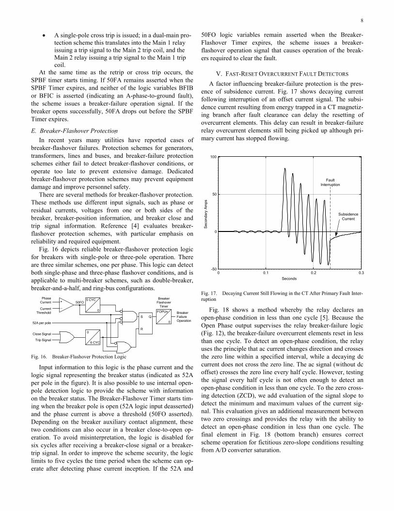
Input information to this logic is the phase current and the logic signal representing the breaker status (indicated as 52A per pole in the figure). It is also possible to use internal open-pole detection logic to provide the scheme with information on the breaker status. The Breaker-Flashover Timer starts tim-ing when the breaker pole is open (52A logic input deasserted) and the phase current is above a threshold (50FO asserted). Depending on the breaker auxiliary contact alignment, these two conditions can also occur in a breaker close-to-open op-eration. To avoid misinterpretation, the logic is disabled for six cycles after receiving a breaker-close signal or a breaker-trip signal. In order to improve the scheme security, the logic limits to five cycles the time period when the scheme can op-erate after detecting phase current inception. If the 52A and
50FO logic variables remain asserted when the Breaker-Flashover Timer expires, the scheme issues a breaker-flashover operation signal that causes operation of the break-ers required to clear the fault.
V. FAST-RESET OVERCURRENT FAULT DETECTORS A factor influencing breaker-failure protection is the pres-
ence of subsidence current. Fig. 17 shows decaying current following interruption of an offset current signal. The subsi-dence current resulting from energy trapped in a CT magnetiz-ing branch after fault clearance can delay the resetting of overcurrent elements. This delay can result in breaker-failure relay overcurrent elements still being picked up although pri-mary current has stopped flowing.
0 0.1 0.2 0.3-50
0
50
100
Sec
onda
ry A
mps
Seconds
Subsidence Current
Fault Interruption
Fig. 17. Decaying Current Still Flowing in the CT After Primary Fault Inter-ruption
Fig. 18 shows a method whereby the relay declares an open-phase condition in less than one cycle [5]. Because the Open Phase output supervises the relay breaker-failure logic (Fig. 12), the breaker-failure overcurrent elements reset in less than one cycle. To detect an open-phase condition, the relay uses the principle that ac current changes direction and crosses the zero line within a specified interval, while a decaying dc current does not cross the zero line. The ac signal (without dc offset) crosses the zero line every half cycle. However, testing the signal every half cycle is not often enough to detect an open-phase condition in less than one cycle. To the zero cross-ing detection (ZCD), we add evaluation of the signal slope to detect the minimum and maximum values of the current sig-nal. This evaluation gives an additional measurement between two zero crossings and provides the relay with the ability to detect an open-phase condition in less than one cycle. The final element in Fig. 18 (bottom branch) ensures correct scheme operation for fictitious zero-slope conditions resulting from A/D converter saturation.

9
21
abs(IA) > 0.9•35•Inom•sqrt(2)
Open Phase
ZCD
dldt ZCD
IA¾ cycle
0
Fig. 18. Algorithm for Resetting the Overcurrent Elements in Less Than One Cycle
VI. BREAKER-FAILURE INITIATE CONSIDERATIONS In a high-voltage substation, protective relays serve the
function of fault detection. Each relay is typically applied to be selective to a given power system zone. To provide redun-dancy and eliminate single points of failure, we often apply multiple relays to cover each zone. Depending on the bus ar-rangement, any given circuit breaker may be called upon to trip by multiple relays detecting faults in zones on either side of the circuit breaker. In modern multifunction relays, each of these relays that trip the circuit breaker may be capable of providing breaker-failure protection. Thus, we have a need to consider how to implement breaker-failure protection when we possibly have breaker-failure functionality available in each of these multiple relays.
It is important to keep in mind that security is of primary importance in designing a breaker-failure scheme [1]. And, since a breaker-failure operation results in tripping breakers that will isolate all of the adjacent zones of the power system, the consequences of breaker-failure false operation are usually very serious. One of the leading causes of breaker-failure mi-soperations is inadvertently initiating the breaker-failure timer. Spurious initiates often come from testing fault detection re-lays that initiate breaker-failure timers. For this reason, it is important to make the system design as simple as possible and to be consistent in the design throughout the substation. Care-ful consideration of where the breaker-failure function will reside in the multiple relays and management of initiate and tripping paths is the key to reducing the possibility of mis-takes.
One factor that will influence the breaker-failure protection system design is the bus arrangement. While there are many common bus arrangements, for the purposes of this discus-sion, we can classify them under three categories:
• Single-breaker simple-bus arrangements • Single-breaker complex-bus arrangements • Double-breaker arrangements
Single-breaker arrangements are those where the circuits are connected to the bus through a single breaker. In complex-bus arrangements, the circuits can be connected to several possible buses via disconnect switches. Double-breaker ar-rangements are those where the circuits are connected to the bus (or buses) via two breakers. Examples are ring buses, breaker-and-a-half buses, or double-breaker double-buses.
Another factor that will influence the design is the type of relay used. In double-breaker arrangements, the currents from
the two breakers are often summed external to the relay. For the bus-zone side of the breaker, the currents around the bus are often summed external to the differential relay, such as with a high-impedance bus relay. In any of these cases, the multifunction relay cannot see the individual breaker currents so these relays are not capable of providing breaker-failure protection. The protection system may consist of a mix of re-lays that see the current through the breaker and those that do not.
A single-breaker/simple-bus arrangement will be used as an example to illustrate the concept of managing the breaker-failure initiate and tripping paths in a design. For this exam-ple, it is assumed that each breaker has two relays covering its branch circuit and a single relay covering the bus zone. It is also assumed that we are going to use the breaker-failure func-tion available in the multifunction relays instead of applying a separate breaker-failure protection system. For the three ex-amples illustrated in Fig. 19, Fig. 20, and Fig. 21, the bus re-lay is assumed to be a type that measures the current flowing in each individual breaker around the bus. For the fourth ex-ample (Fig. 22) the bus relay is assumed to be a type that has the bus currents summed outside the relay.
Fig. 19 illustrates the simplest application where each relay takes care of breaker-failure timing for all fault trips that it initiates. There is no routing of external breaker-failure initiate (BFI) signals. In this configuration, when a relay is isolated from the system for testing, there are no BFI signals to be concerned with. When an individual relay is out of service or has failed, there is no loss of breaker-failure protection.
1
LINE W
21BW
21AW
BF1
BF1
87BN
BF1
BUS N
Fig. 19. Single-Breaker Simple-Bus, Breaker-Failure Logic Implemented in Each Relay
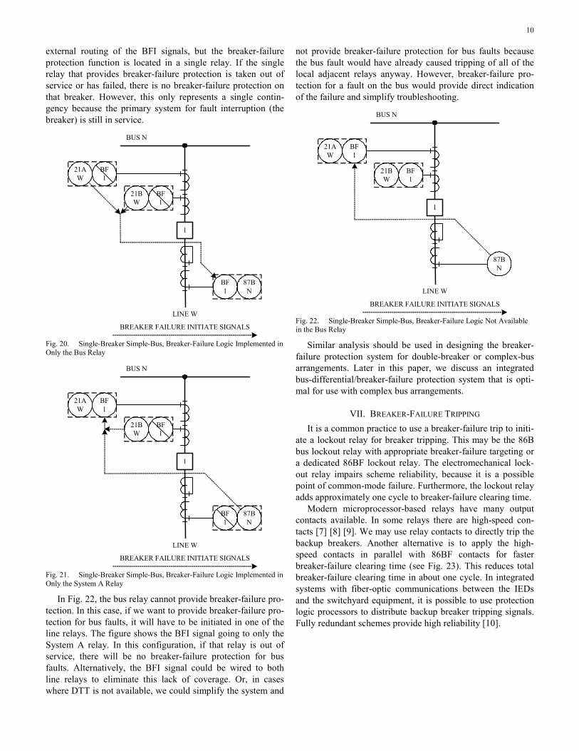
Fig. 20 and Fig. 21 are variations on the same approach. All three fault-detection relays that trip the breaker are capable of providing breaker-failure protection, but the function is enabled in only one of the relays. The configuration illustrated in Fig. 20 might be preferable, because the tripping require-ments for a bus fault are very nearly the same as the tripping requirements for a breaker failure. If direct transfer trip (DTT) of the remote breaker is available, the configuration illustrated in Fig. 21 might be preferable. In this configuration, there is
10
external routing of the BFI signals, but the breaker-failure protection function is located in a single relay. If the single relay that provides breaker-failure protection is taken out of service or has failed, there is no breaker-failure protection on that breaker. However, this only represents a single contin-gency because the primary system for fault interruption (the breaker) is still in service.
1
LINE W
21BW
21AW
BF1
BF1
87BN
BF1
BUS N
BREAKER FAILURE INITIATE SIGNALS
Fig. 20. Single-Breaker Simple-Bus, Breaker-Failure Logic Implemented in Only the Bus Relay
1
LINE W
21BW
21AW
BF1
BF1
87BN
BF1
BUS N
BREAKER FAILURE INITIATE SIGNALS
Fig. 21. Single-Breaker Simple-Bus, Breaker-Failure Logic Implemented in Only the System A Relay
In Fig. 22, the bus relay cannot provide breaker-failure pro-tection. In this case, if we want to provide breaker-failure pro-tection for bus faults, it will have to be initiated in one of the line relays. The figure shows the BFI signal going to only the System A relay. In this configuration, if that relay is out of service, there will be no breaker-failure protection for bus faults. Alternatively, the BFI signal could be wired to both line relays to eliminate this lack of coverage. Or, in cases where DTT is not available, we could simplify the system and
not provide breaker-failure protection for bus faults because the bus fault would have already caused tripping of all of the local adjacent relays anyway. However, breaker-failure pro-tection for a fault on the bus would provide direct indication of the failure and simplify troubleshooting.
1
LINE W
21BW
21AW
BF1
BF1
87BN
BUS N
BREAKER FAILURE INITIATE SIGNALS
Fig. 22. Single-Breaker Simple-Bus, Breaker-Failure Logic Not Available in the Bus Relay
Similar analysis should be used in designing the breaker-failure protection system for double-breaker or complex-bus arrangements. Later in this paper, we discuss an integrated bus-differential/breaker-failure protection system that is opti-mal for use with complex bus arrangements.
VII. BREAKER-FAILURE TRIPPING It is a common practice to use a breaker-failure trip to initi-
ate a lockout relay for breaker tripping. This may be the 86B bus lockout relay with appropriate breaker-failure targeting or a dedicated 86BF lockout relay. The electromechanical lock-out relay impairs scheme reliability, because it is a possible point of common-mode failure. Furthermore, the lockout relay adds approximately one cycle to breaker-failure clearing time.
Modern microprocessor-based relays have many output contacts available. In some relays there are high-speed con-tacts [7] [8] [9]. We may use relay contacts to directly trip the backup breakers. Another alternative is to apply the high-speed contacts in parallel with 86BF contacts for faster breaker-failure clearing time (see Fig. 23). This reduces total breaker-failure clearing time in about one cycle. In integrated systems with fiber-optic communications between the IEDs and the switchyard equipment, it is possible to use protection logic processors to distribute backup breaker tripping signals. Fully redundant schemes provide high reliability [10].

11
Relay Trip A
IA
50
AND
BFTrip
OR
62PU62
0
86BF
52TC
BF Trip 86BF
1 52TC
BF Trip 86BF
2 52TC
BF Trip 86BF
3
Fig. 23. Breaker-Failure Tripping Scheme with Parallel High-Speed Output Contacts
In many cases the breaker-failure scheme operation may not be enough to completely isolate the faulted section. We may also need one or more remote breakers tripped. One pos-sibility is to let the remote backup protection trip the remote breaker. Another alternative is for the breaker-failure scheme to send a DTT signal to the remote breaker via a communica-tions channel. Below we analyze some of these cases.
We can use Fig. 1 to analyze breaker-failure tripping logic in a substation (Substation C) with a single-bus single-breaker configuration. Breaker 5 will be called upon to trip by primary relays for two different fault locations: 1) fault on Line CD, 2) fault on Bus C. For a fault on Line CD, if Breaker 5 fails to trip, the breaker-failure scheme trips Breakers 2 and T. The primary protection at the remote line end trips Breaker 6 to completely clear the fault. After that, Breaker 6 executes its reclosing sequence, if any. For a fault at Bus C with Breaker 5 failing to operate, the breaker-failure scheme trips Breakers 2 and T. However we now need to wait for the remote backup protection (distance Zone 2, for example) to trip Breaker 6. This delays fault clearing and allows Breaker 6 to reclose un-necessarily for a fault at the remote bus. If a communications channel is available on Line CD, the breaker-failure logic can accelerate fault clearing by sending a DTT signal to Breaker 6. The scheme can also use the channel to block Breaker 6 reclo-sure.
Fig. 24 depicts a single-bus single-breaker configuration in Substation C, including a power transformer. In this case, we have omitted the transformer breaker, and have used instead a motor-operated disconnect. Breaker 4 will be called upon to trip for faults in three zones: Line BC, Bus C, and transformer. For a fault in the transformer, the transformer primary protec-tion trips Breakers 3, 4, 5, and 6, then the motor-operated dis-connect automatically opens to isolate the faulted transformer. Later Breakers 3, 4, and 5 reclose to restore service to Bus C. If Breaker 4 fails to trip, the breaker-failure scheme trips and locks out Breakers 3, 5, and 6. Breaker 2 at Substation B is again the concern. We could rely on remote backup to sup-plement local backup protection for this breaker. However, for the transformer zone, relays at Breaker 2 may not have the sensitivity to detect all faults detected by the sensitive trans-
former protection. The best solution is for the breaker-failure logic to initiate a DTT of Breaker 2. For this we need a com-munications channel on Line BC.
Ring-bus and breaker-and-a-half arrangements also require tripping remote breakers to completely isolate the faulted sec-tion. Consider Breaker 4 at Substation C (Fig. 25), which is a ring bus. With a ring bus, we must trip multiple breakers for any fault. For a fault on Line BC, line primary protection trips Breakers 2, 4, and 6. If Breaker 4 fails, Breakers 2 and 6 are already open from the original trip, and the breaker-failure scheme trips Breaker 3, which removes the source of infeed from D and E. In order to clear the fault, we also need to trip Breaker 1. One possibility is to rely on remote backup. There-fore, the backup relays at 1 (distance Zone 3, for example) must have enough sensitivity to cover 100 percent of line BC, or CD if we consider the failure of Breaker 3. Removal of infeed by local breaker-failure protection eases the task. The other alternative is a DTT of Breaker 1 initiated by the breaker-failure scheme. This reduces fault-clearing time to breaker-failure time and reduces the reliance on Zone 3 reach.
1 3 5 7
2 4
A
B
DC
Breaker 3, 5, and 6Trip by Local Backup
6
Breaker4 Fails
Motor-OperatedDisconnect
Fig. 24. Breaker-Failure Tripping Logic for a Bus Involving a Transformer
1 3 7
2
4
A
B
DBreaker 3 and 6
Trip by Local Backup
Breaker4 Fails
8
E
5
6
C
Fig. 25. Breaker-Failure Tripping Logic for a Ring-Bus Configuration
VIII. INTEGRATED BUS AND BREAKER-FAILURE PROTECTION Bus protection was the first station-wide protection.
Breaker-failure protection became the second station-wide protection function when it replaced the use of remote Zone 2
12
distance relay elements for local backup protection. While one relay provided system-wide bus protection, implementation of breaker-failure protection was traditionally through the use of separate relays, one breaker-failure relay for each station breaker [11].
This device separation results in additional wiring and du-plication of common functionality. For example, in complex bus arrangements, bus protection uses disconnect status from each terminal to assign the proper currents to the differential element and to determine which terminals to trip for bus faults. Breaker-failure protection uses the same information to determine which breakers to trip for breaker-failure condi-tions.
Integrated bus and breaker-failure protection eliminates duplication of common functionality, minimizes wiring, and simplifies protection scheme design. Narayan and Brulhart [12] described a method of breaker-failure protection with bus protection implemented in analog electronic relays. Instead of using an overcurrent relay for detecting a breaker-failure con-dition, this method extends the zone of bus protection to in-clude the zone of the faulted breaker. The proposed scheme uses an image of the bus sections corresponding to the actual operating conditions. When breaker failure occurs, the relay trips all breakers supplying the fault current connected to the same bus as the faulted breaker.
For microprocessor-based digital bus protection, it is com-mon to integrate many bus-protection functions into the same relay. Peck, Nygaad, and Wadelius [13] introduced breaker-failure protection integrated as an option for each terminal in a distributed architecture. Each terminal unit contains a three-phase overcurrent element with fast pickup and reset, and two timers. Separate binary inputs on each terminal unit provide breaker-failure initiation from an external protection device.
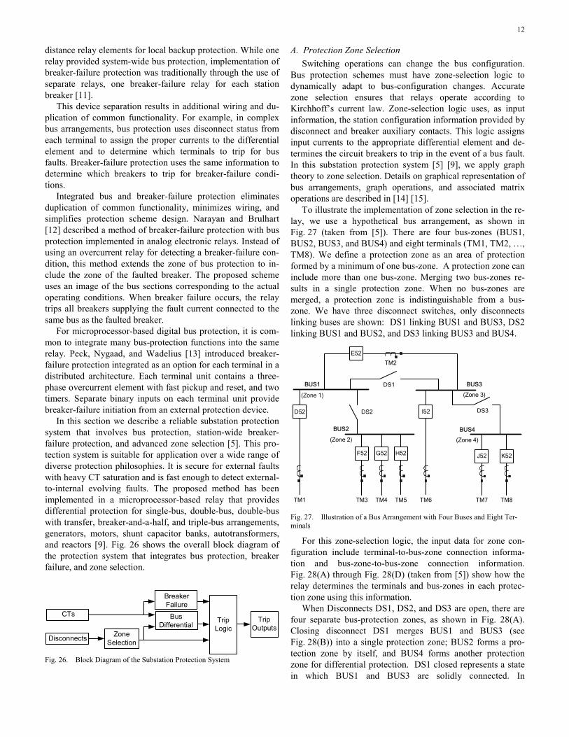
In this section we describe a reliable substation protection system that involves bus protection, station-wide breaker-failure protection, and advanced zone selection [5]. This pro-tection system is suitable for application over a wide range of diverse protection philosophies. It is secure for external faults with heavy CT saturation and is fast enough to detect external-to-internal evolving faults. The proposed method has been implemented in a microprocessor-based relay that provides differential protection for single-bus, double-bus, double-bus with transfer, breaker-and-a-half, and triple-bus arrangements, generators, motors, shunt capacitor banks, autotransformers, and reactors [9]. Fig. 26 shows the overall block diagram of the protection system that integrates bus protection, breaker failure, and zone selection.
Bus Differential
Trip Logic
Trip Outputs
CTs
Breaker Failure
Zone SelectionDisconnects
Fig. 26. Block Diagram of the Substation Protection System
A. Protection Zone Selection Switching operations can change the bus configuration.
Bus protection schemes must have zone-selection logic to dynamically adapt to bus-configuration changes. Accurate zone selection ensures that relays operate according to Kirchhoff’s current law. Zone-selection logic uses, as input information, the station configuration information provided by disconnect and breaker auxiliary contacts. This logic assigns input currents to the appropriate differential element and de-termines the circuit breakers to trip in the event of a bus fault. In this substation protection system [5] [9], we apply graph theory to zone selection. Details on graphical representation of bus arrangements, graph operations, and associated matrix operations are described in [14] [15].
To illustrate the implementation of zone selection in the re-lay, we use a hypothetical bus arrangement, as shown in Fig. 27 (taken from [5]). There are four bus-zones (BUS1, BUS2, BUS3, and BUS4) and eight terminals (TM1, TM2, …, TM8). We define a protection zone as an area of protection formed by a minimum of one bus-zone. A protection zone can include more than one bus-zone. Merging two bus-zones re-sults in a single protection zone. When no bus-zones are merged, a protection zone is indistinguishable from a bus-zone. We have three disconnect switches, only disconnects linking buses are shown: DS1 linking BUS1 and BUS3, DS2 linking BUS1 and BUS2, and DS3 linking BUS3 and BUS4.
BUS1
DS2
TM2
D52
TM5TM3 TM7 TM8
BUS2
BUS3
BUS4
TM4
DS3
TM6TM1
F52 G52 H52
I52
J52 K52
E52
DS1
(Zone 1)
(Zone 2)
(Zone 3)
(Zone 4)
Fig. 27. Illustration of a Bus Arrangement with Four Buses and Eight Ter-minals
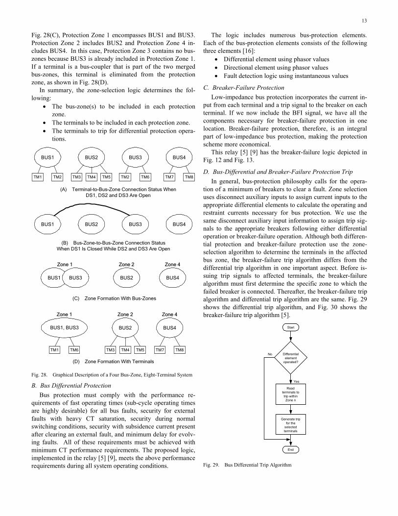
For this zone-selection logic, the input data for zone con-figuration include terminal-to-bus-zone connection informa-tion and bus-zone-to-bus-zone connection information. Fig. 28(A) through Fig. 28(D) (taken from [5]) show how the relay determines the terminals and bus-zones in each protec-tion zone using this information.
When Disconnects DS1, DS2, and DS3 are open, there are four separate bus-protection zones, as shown in Fig. 28(A). Closing disconnect DS1 merges BUS1 and BUS3 (see Fig. 28(B)) into a single protection zone; BUS2 forms a pro-tection zone by itself, and BUS4 forms another protection zone for differential protection. DS1 closed represents a state in which BUS1 and BUS3 are solidly connected. In
13
Fig. 28(C), Protection Zone 1 encompasses BUS1 and BUS3. Protection Zone 2 includes BUS2 and Protection Zone 4 in-cludes BUS4. In this case, Protection Zone 3 contains no bus-zones because BUS3 is already included in Protection Zone 1. If a terminal is a bus-coupler that is part of the two merged bus-zones, this terminal is eliminated from the protection zone, as shown in Fig. 28(D).
In summary, the zone-selection logic determines the fol-lowing:
• The bus-zone(s) to be included in each protection zone.
• The terminals to be included in each protection zone. • The terminals to trip for differential protection opera-
tions.
BUS1 BUS2 BUS3 BUS4
(A) Terminal-to-Bus-Zone Connection Status When DS1, DS2 and DS3 Are Open
(B) Bus-Zone-to-Bus-Zone Connection Status When DS1 Is Closed While DS2 and DS3 Are Open
(C) Zone Formation With Bus-Zones
(D) Zone Formation With Terminals
TM7 TM8
BUS2 BUS4
Zone 1 Zone 2 Zone 4
BUS2 BUS4BUS1, BUS3
Zone 1 Zone 2 Zone 4
TM1 TM6 TM3 TM4 TM5 TM7 TM8
BUS1 BUS2 BUS3 BUS4
TM1 TM2 TM3 TM4 TM5 TM2 TM6
BUS1 BUS3
Fig. 28. Graphical Description of a Four Bus-Zone, Eight-Terminal System
B. Bus Differential Protection Bus protection must comply with the performance re-
quirements of fast operating times (sub-cycle operating times are highly desirable) for all bus faults, security for external faults with heavy CT saturation, security during normal switching conditions, security with subsidence current present after clearing an external fault, and minimum delay for evolv-ing faults. All of these requirements must be achieved with minimum CT performance requirements. The proposed logic, implemented in the relay [5] [9], meets the above performance requirements during all system operating conditions.
The logic includes numerous bus-protection elements. Each of the bus-protection elements consists of the following three elements [16]:
• Differential element using phasor values • Directional element using phasor values • Fault detection logic using instantaneous values
C. Breaker-Failure Protection Low-impedance bus protection incorporates the current in-
put from each terminal and a trip signal to the breaker on each terminal. If we now include the BFI signal, we have all the components necessary for breaker-failure protection in one location. Breaker-failure protection, therefore, is an integral part of low-impedance bus protection, making the protection scheme more economical.
This relay [5] [9] has the breaker-failure logic depicted in Fig. 12 and Fig. 13.
D. Bus-Differential and Breaker-Failure Protection Trip In general, bus-protection philosophy calls for the opera-
tion of a minimum of breakers to clear a fault. Zone selection uses disconnect auxiliary inputs to assign current inputs to the appropriate differential elements to calculate the operating and restraint currents necessary for bus protection. We use the same disconnect auxiliary input information to assign trip sig-nals to the appropriate breakers following either differential operation or breaker-failure operation. Although both differen-tial protection and breaker-failure protection use the zone-selection algorithm to determine the terminals in the affected bus zone, the breaker-failure trip algorithm differs from the differential trip algorithm in one important aspect. Before is-suing trip signals to affected terminals, the breaker-failure algorithm must first determine the specific zone to which the failed breaker is connected. Thereafter, the breaker-failure trip algorithm and differential trip algorithm are the same. Fig. 29 shows the differential trip algorithm, and Fig. 30 shows the breaker-failure trip algorithm [5].
Differentialelement
operated?
Readterminals totrip withinZone n
Generate tripfor the
selectedterminals
Start
End
No
Yes
Fig. 29. Bus Differential Trip Algorithm

14
Breakerfailure
elementoperated?
Read zone(s)that includethe failedterminal
Readterminals totrip within
Zone n
Start
End
No
Yes
Generate tripfor terminals in
the involvedzones
Fig. 30. Breaker-Failure Trip Algorithm
IX. BREAKER-FAILURE PROTECTION IN DISTRIBUTION SUBSTATIONS
At medium-voltage-level distribution substations, such as 13.8 kV, protection philosophies typically do not consider local backup protection, so breaker-failure protection is not applied. This causes long breaker-operation times and selec-tivity problems. For example, when there is a feeder fault (see Fig. 31) and the feeder breaker (Breaker B) fails to operate, the most common practice is to clear the fault with the trans-former backup protection (Breaker A). This protection is co-ordinated with the feeder protection, which has a very large operating time (i.e., seconds) that depends on the magnitude of the fault current. As a result, the transformer wears faster. In addition, transformer-breaker tripping causes service interrup-tion to all feeder loads. This means that the effect of a breaker failure on selectivity is similar to the result of a bus fault.
Another drawback to the lack of breaker-failure protection is the long service-restoration time. If Breaker A trips in the typical substation shown in Fig. 31, the operator ignores whether the service interruption is caused by a bus fault (Fault F1) or the result of a backup protection operation for a feeder fault (Fault F2). Consequently, the operator’s strategy is to open the four feeder breakers to locate the fault and to start the restoration process. Once all breakers are open, Breaker A is closed again, as a test, to identify whether there is a bus fault. If Breaker A trips again, there is a bus fault, but in this process the transformer is again exposed to fault current, and load con-tinues to be out of service. For the substation depicted in Fig. 31, we estimate that it takes about 10 minutes to identify a bus fault; this period does not include the total load restora-tion time.
Fig. 31. Distribution Substation Equipped to Implement Breaker-Failure Protection
The protection scheme can be improved by using a combi-nation of multifunction relays and a protection logic processor (see Fig. 31) to implement the breaker-failure logic presented in Fig. 32 [17]. This logic uses phase and ground instantane-ous overcurrent elements from the feeder and the transformer low-voltage-side multifunction relays; these overcurrent ele-ments serve as fault detectors. Feeder fault detector pickup current must be setup above the feeder maximum load current; the transformer low-voltage-side fault detectors must have a pickup current greater than the transformer normal operating current. The logic requires a breaker-failure timer to coordi-nate the scheme with the feeder protection; the timer is set up with an operating time equal to the sum of the relay and breaker operating times, and the fault-detector reset time, plus a security margin. As an example, Fig. 31 shows a setting of 10 cycles in the breaker-failure timer. We will analyze feeder and bus faults in the circuit depicted in Fig. 31 to explain the operation of the breaker-failure logic.
When Fault F2 occurs at Feeder A1 (see Fig. 31), the A1 feeder primary protection trips, so the breaker-failure logic shown in Fig. 32 starts (enables the AND gate). The logic op-eration is supervised by the two current detectors, which, through an OR gate, create the other input to the AND gate. If the feeder primary protection tripped, but there is still fault current at the feeder, the circuit breaker must have failed to operate. Consequently, after a small time delay (shown as 3 cycles in Fig. 31), the logic sends a retrip signal to the breaker. If the breaker does not trip at this time, and the A1 feeder pri-mary protection and the current detectors remain operated after the breaker-failure time delay, the protection logic proc-essor receives information. The protection logic processor communicates with the feeder relays and with the transformer low-voltage-side relay to trip all the circuit breakers associated with the bus.

15
BreakerRetrip
Breaker Retrip
From Feeder A2 Relay
From Feeder A3 Relay
From Feeder A4 Relay
To Feeder A1 RelayTripping Logic
To Feeder A2 Relay
To Feeder A3 Relay
To Feeder A1 Relay
To Transf. LV Side Relay
From Primary Relays
To Transf. HV Side Relay Tripping Logic
Phase CurrentDetectors
Ground CurrentDetectors
OR
ANDOR
3 ~
0
10 ~
0
10 ~
0
3 ~
0
Transf. LV Side Relay
Feeder A1 Relay
From Primary Relays
Phase CurrentDetectors
Ground CurrentDetectors
OR
AND
ProtectionLogic
Processor Fig. 32. Breaker-Failure Logic for a Distribution Substation
When Fault F1 occurs at the bus (see Fig. 31) the trans-former low-voltage-side relay operates. This initiates the breaker-failure backup protection logic shown in Fig. 32. The logic operation is similar to that explained in the case of Fault F2. The only difference is that in this case the protection logic processor also sends a signal to the transformer high-voltage-side relay, which trips the high-voltage breaker.
The breaker-failure logic clears the fault in a much shorter time than transformer backup protection schemes, whether the fault is at a feeder (feeder-backup protection), or at the low-side bus (transformer-backup protection). This reduces trans-former wear and improves transformer lifetime. In addition, the breaker-failure backup logic quickly identifies a bus fault and issues an alarm. With this information, the operator may take immediate action, which reduces substation restoration time.
X. CONCLUSIONS • Local backup protection has greater selectivity, greater
sensitivity, and faster operation than remote backup pro-tection. In many cases, with modern multifunction relays, local backup is also an economical solution, because it requires no additional equipment.
• Modern breaker-failure schemes are applicable to all bus configurations, are practically immune to current redistri-bution problems in multi-breaker applications, and are not affected by CT saturation.
• Single-phase faults result in longer critical clearing times than multiphase faults. In single-pole tripping applica-tions, using a longer breaker-failure time for single-phase faults improves scheme security for the most frequent type of fault.
• When several multifunction relays trip the same breaker, each relay may be capable of providing breaker-failure protection. Relay multifunctionality gives design flexibil-ity and requires careful consideration of the relay where the function will reside, and careful selection of initiate and tripping paths.
• Using relay output contacts for breaker-failure tripping eliminates the need for a lockout relay, thus improving scheme reliability and reducing operating time.
• Integrated bus and breaker-failure protection eliminates duplication of common functionality, minimizes wiring and simplifies design.
• The use of multifunction relays combined with a protec-tion logic processor in distribution substations allows providing low-cost breaker-failure protection schemes, which reduce the duration of faults where the feeder cir-cuit breaker or the transformer low-voltage-side relay fails to operate. It also reduces the service restoration time.
XI. APPENDIX Fig. 33 shows the model (taken from [2]) used for the digi-
tal simulations discussed in Section III of the paper. This sys-tem is developed from the two-area example power system in [18] with some slight modifications. The model was devel-oped on a real-time digital simulator manufactured by RTDS Technologies.

16
Bus G
Gen F
Gen GLine 9
Bus F
Line 8
Bus ELoad
Line 7
Bus D
Line 5Line 6
Bus CLoad
Line 3Line 4
Bus B
Gen B
Line 1Line 2Bus A
Gen A
Relay
Fault
Fig. 33. Example Power System
XII. ACKNOWLEDGEMENT The authors want to express their gratitude to Armando
Guzmán, Casper Labuschagne, Bai Lin Qin (authors of [5]), and also to David Sánchez, Eliseo Alcázar, and Oscar Márquez (coauthors of [17]), all from SEL, for their kind per-mission to use portions of their papers in our paper.
XIII. REFERENCES [1] M. Thompson, “Fundamentals and Advancements in Breaker-Failure
Protection,” 53rd Annual Georgia Tech Protective Relaying Conference, Atlanta, GA, May 5–7, 1999.
[2] J. Mooney and N. Fischer, “Application Guidelines for Ppower Swing Detection on Transmission Systems,” in 2005 32nd Annual Western Protective Relay Conference.
[3] IEEE Power Engineering Society, IEEE Tutorial on the Protection of Synchronous Generators. IEEE Publication 95 TP 102, 1995.
[4] R. Sandoval and J. Leon, “Evaluation of methods for breaker flashover protection,” in 2004 31st Annual Western Protective Relay Conference.
[5] A. Guzmán, C. Labuschagne, and B. L. Qin, “Reliable busbar and breaker-failure protection with advanced zone selection,” in 2004 31st Annual Western Protective Relay Conference.
[6] W.A. Elmore, Protective Relaying Theory and Applications. New York-Basel: Marcel Dekker, Inc., 2004.
[7] SEL-421 Reference Manual, Schweitzer Engineering Laboratories, Inc., Pullman, WA, 2006, date code 20060814.
[8] SEL-352 Reference Manual, Schweitzer Engineering Laboratories, Inc., Pullman, WA, date code 20051202.
[9] SEL-487B Reference Manual, Schweitzer Engineering Laboratories, Inc., Pullman, WA, date code 20060905.
[10] D. Sánchez, R. D. González, E. Valdez, C.M. Robledo, R.J. Cavazos, J.J. Luna, S.D. González, and G.M. Robledo, “Modernization project: modular control house for Nava electrical substation,” 19th Summer Power Meeting of the IEEE Mexico Section, Acapulco, Gro., Mexico, July 2005 (in Spanish).
[11] J. L. Blackburn, Protective Relaying, Principles and Applications, 2nd Edition. New York-Basel: Marcel Dekker, Inc., 1998.
[12] V. Narayan and G. Brulhart, “Busbar protection with enhanced perform-ance,” Proc. IEE 3rd International Conference on Developments in Power System Protection, April 1985, pp. 218–222.
[13] D. M. Peck, B. Nygaad, and K. Wadelius, “A new numerical busbar protection system with bay-oriented structure,” Proc. IEE 5th Interna-tional Conference on Developments in Power System Protection, 1993, Publication No. 368, pp. 228–231.
[14] B.L. Qin, A. Guzmán, and E.O. Schweitzer, III, “A new method for protection zone selection in microprocessor-based bus relays,” IEEE Trans. Power Del., vol.15, no.3, pp. 876-887, July 2000.
[15] B.L. Qin, and A. Guzmán, “System for protection zone selection in microprocessor-based relays in an electric power system,” US Patent 6,411,865, Jun. 25, 2002.
[16] A. Guzmán, “Restraint-type differential relay,” US Patent 6,341,055, Jan. 22, 2002.
[17] D. Sánchez, E. Alcázar, O. A. Márquez, and H. J. Altuve, “Multifunc-tion relays and protection logic processors in distribution substation ap-plications,” SEL 21ST Annual Technical Seminar at WPRC, Spokane, WA, October 24, 2005.
[18] P. Kundur, Power System Stability and Control. New York: McGraw-Hill, 1994.
XIV. BIOGRAPHIES Héctor J. Altuve received his BSEE degree in 1969 from the Central
University of Las Villas, Santa Clara, Cuba, and his Ph.D. in 1981 from Kiev Polytechnic Institute, Kiev, Ukraine. From 1969 until 1993, Dr. Altuve served on the faculty of the Electrical Engineering School, at the Central University of Las Villas. He served as professor, Graduate Doctoral Program, Mechanical and Electrical Engineering School, at the Autonomous University of Nuevo León, Monterrey, Mexico, from 1993 to 2000. In 1999–2000, he was the Schweitzer Visiting Professor at Washington State University’s De-partment of Electrical Engineering. In January 2001, Dr. Altuve joined Schweitzer Engineering Laboratories, Inc., where he is currently a Distin-guished Engineer and Director of Technology for Latin America. He has authored and coauthored more than 100 technical papers and holds three patents. His main research interests are in power system protection, control and monitoring. Dr. Altuve is an IEEE Senior Member, and a PES Distin-guished Lecturer.

17
Michael J. Thompson, P.E. received his BS, Magna Cum Laude from Bradley University in 1981 and an MBA from Eastern Illinois University in 1991. He has broad experience in the field of power system operations and protection. Upon graduating, he served nearly 15 years at Central Illinois Public Service (now AMEREN) where he worked in distribution and substa-tion field engineering before taking over responsibility for system protection engineering. Prior to joining Schweitzer Engineering Laboratories in 2001, he was involved in the development of a number of numerical protective relays. He is a Senior Member of the IEEE and a member of the Substation And Rotating Machinery Subcommittees of the IEEE, PES, Power System Relay-ing Committee. Michael is a registered Professional Engineer in the State of Washington and holds a patent for integrated protection and control system architecture.
Joe Mooney, P.E. received his B.S. in Electrical Engineering from Wash-ington State University in 1985. He joined Pacific Gas and Electric Company upon graduation as a System Protection Engineer. In 1989, he left Pacific Gas and Electric and was employed by Bonneville Power Administration as a System Protection Maintenance District Supervisor. In 1991, he left Bonne-ville Power Administration and joined Schweitzer Engineering Laboratories, Inc. as an Application Engineer. Shortly after starting with SEL, he was pro-moted to Application Engineering Manager where he remained for nearly three years. He is currently the manager of the Power Engineering Group of the Research and Development department at Schweitzer Engineering Labora-tories, Inc. He is a registered Professional Engineer in the State of California and Washington.
Copyright © SEL 2006
(All rights reserved) 20060905 TP6262-01