Advancements with Regenerative Airheater Design ... with Regenerative Airheater Design, Performance...
16
POWER-GEN Europe 7-9 June 2011, FIERA, MILANO – MILAN - ITALY POWER-GEN EUROPE 2011, ID-1546 Track 4: Coal Firing, Biomass Combustion and Energy from Waste, Session -5 1 Advancements with Regenerative Airheater Design, Performance and Reliability Stephen K. Storm, C.E.M. Stephen Storm, Inc. Senior Consultant P.O. Box 398 (Mail) 234 Glenbrook Springs (Deliveries) New London, NC 28127 Cellular Phone : (704) 796-2349 (USA) Office: (336) 461-3015 (USA) [email protected] Ph.D. Andrea Zucchelli Assistant Professor at the University of Bologna, Engineering Faculty, Mechanical Engineering Department, viale Risorgimento, 40136, Bologna, Italy Tel: +39 051 209 34 54 Cell: +39 335427236 John Guffre, P.E. Chief Research Scientist Paragon Airheater Technologies (USA) 23143 Temescal Canyon Rd., Suite B Corona, CA 92883 Telephone: 888-488-3100 [email protected] Introduction Serving as the last heat trap for the boiler system, a regenerative airheater typically accounts for over 10% of a plants thermal efficiency on a typical steam generator. Considering this, when evaluating the performance of an airheater one should take into account all of the process variables. Along with the advancement with air pollution control equipment and soot blower technology, the U.S. Power industry has become more “fuels flexible”, but subjected to greater reliability challenges. Fuel blends with challenging mineral ash constituents, de-activated SCR catalysts, NH 3 slip and/or sorbent injections for SO 3 control can accelerate common issues that often include fouling, plugging and/or corrosion of the airheater. Regenerative airheaters serve as a heat exchanger which allows for proper preheating of combustion air allowing for more efficient combustion. If non-optimal performance is present not only is unit efficiency in jeopardy but so also unit availability and/or the performance of the air pollution control equipment. Airheater problems can lead to unit de-rates which result from fan capacity issues, improper combustion temperature and/or unacceptable gas temperatures entering the stack. Higher than desirable air heater gas outlet temperatures can reduce the collection efficiency of electrostatic precipitators and have negative effects on the reliability of baghouses. Considering this, the purpose of this paper is to review recent advancements in process evaluation and research and development being completed to help achieve improved air heater and overall unit efficiency, while simultaneously reducing forced outages related to the airheater. Topics covered within this paper include: 1) Operational and Maintenance Considerations 2) Mechanical Component Considerations 3) Element material and coating considerations
Transcript of Advancements with Regenerative Airheater Design ... with Regenerative Airheater Design, Performance...
POWER-GEN Europe 7-9 June 2011, FIERA, MILANO – MILAN - ITALY
POWER-GEN EUROPE 2011, ID-1546 Track 4: Coal Firing, Biomass Combustion and Energy from Waste, Session -5
1
Advancements with Regenerative Airheater Design, Performance and Reliability
Stephen K. Storm, C.E.M.
Stephen Storm, Inc. Senior Consultant P.O. Box 398 (Mail)
234 Glenbrook Springs (Deliveries) New London, NC 28127
Cellular Phone : (704) 796-2349 (USA) Office: (336) 461-3015 (USA) [email protected]
Ph.D. Andrea Zucchelli
Assistant Professor at the University of Bologna, Engineering Faculty, Mechanical
Engineering Department, viale Risorgimento, 40136, Bologna, Italy Tel: +39 051 209 34 54 Cell: +39 335427236
John Guffre, P.E. Chief Research Scientist
Paragon Airheater Technologies (USA)
23143 Temescal Canyon Rd., Suite B Corona, CA 92883
Telephone: 888-488-3100 [email protected]
Introduction Serving as the last heat trap for the boiler system, a regenerative airheater typically accounts for over 10% of a plants thermal efficiency on a typical steam generator. Considering this, when
evaluating the performance of an airheater one should take into account all of the process variables.
Along with the advancement with air pollution control equipment and soot blower technology,
the U.S. Power industry has become more “fuels flexible”, but subjected to greater reliability
challenges. Fuel blends with challenging mineral ash constituents, de-activated SCR catalysts,
NH3 slip and/or sorbent injections for SO3 control can accelerate common issues that often
include fouling, plugging and/or corrosion of the airheater. Regenerative airheaters serve as a heat exchanger which allows for proper preheating of combustion air allowing for more efficient combustion. If non-optimal performance is present not only is unit efficiency in jeopardy but so also unit availability and/or the performance of the air pollution control equipment. Airheater problems can lead to unit de-rates which result from fan capacity issues, improper combustion temperature and/or unacceptable gas temperatures entering the stack. Higher than desirable air heater gas outlet temperatures can reduce the collection efficiency of electrostatic precipitators and have negative effects on the reliability of baghouses. Considering this, the purpose of this paper is to review recent advancements in process evaluation and research and development being completed to help achieve improved air heater and overall unit efficiency, while simultaneously reducing forced outages related to the airheater. Topics covered within this paper include:
1) Operational and Maintenance Considerations 2) Mechanical Component Considerations 3) Element material and coating considerations
POWER-GEN Europe 7-9 June 2011, FIERA, MILANO – MILAN - ITALY
POWER-GEN EUROPE 2011, ID-1546 Track 4: Coal Firing, Biomass Combustion and Energy from Waste, Session -5
2
Operational and Maintenance Considerations
Both air heater leakage and upstream air in-leakage from a boilers penthouse can significantly impact
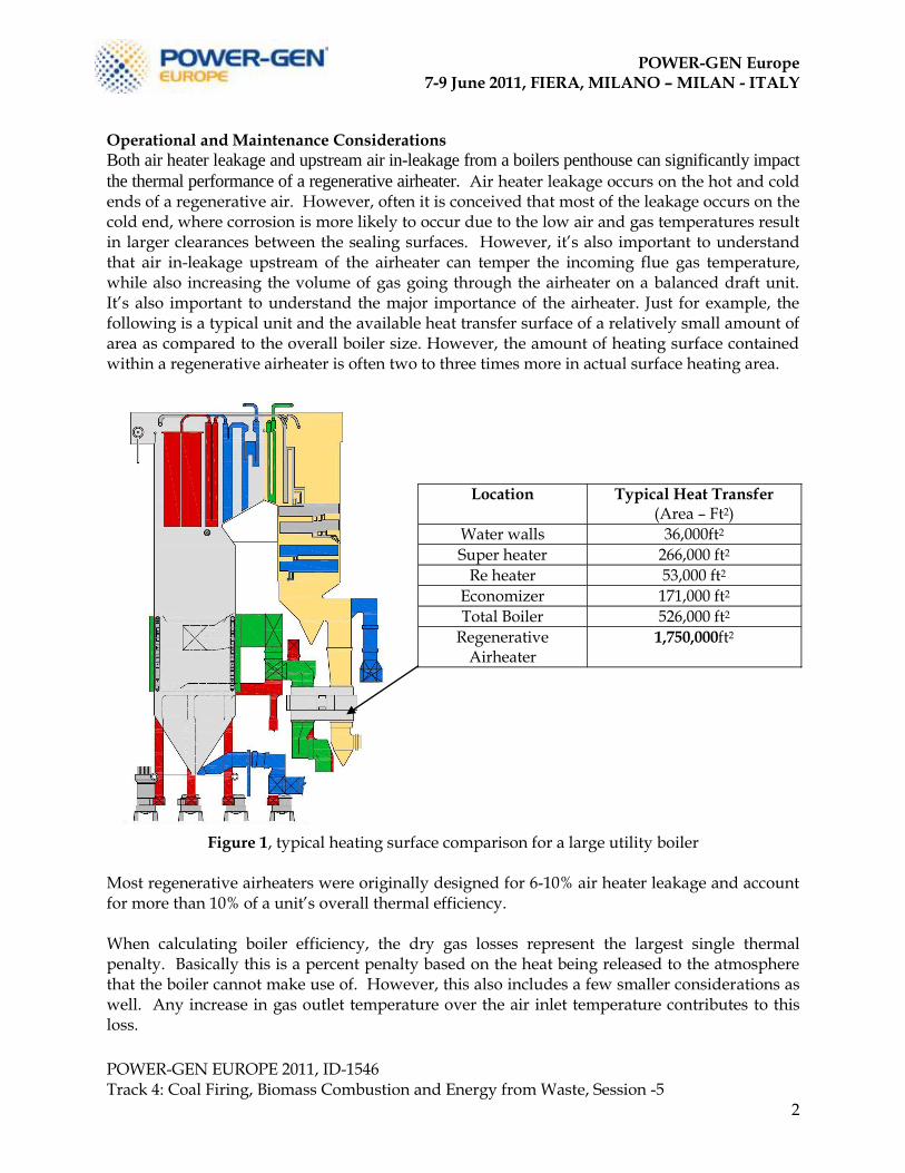
the thermal performance of a regenerative airheater. Air heater leakage occurs on the hot and cold ends of a regenerative air. However, often it is conceived that most of the leakage occurs on the cold end, where corrosion is more likely to occur due to the low air and gas temperatures result in larger clearances between the sealing surfaces. However, it’s also important to understand that air in-leakage upstream of the airheater can temper the incoming flue gas temperature, while also increasing the volume of gas going through the airheater on a balanced draft unit. It’s also important to understand the major importance of the airheater. Just for example, the following is a typical unit and the available heat transfer surface of a relatively small amount of area as compared to the overall boiler size. However, the amount of heating surface contained within a regenerative airheater is often two to three times more in actual surface heating area.
Figure 1, typical heating surface comparison for a large utility boiler
Most regenerative airheaters were originally designed for 6-10% air heater leakage and account for more than 10% of a unit’s overall thermal efficiency. When calculating boiler efficiency, the dry gas losses represent the largest single thermal penalty. Basically this is a percent penalty based on the heat being released to the atmosphere that the boiler cannot make use of. However, this also includes a few smaller considerations as well. Any increase in gas outlet temperature over the air inlet temperature contributes to this loss.
Location Typical Heat Transfer (Area – Ft2)
Water walls 36,000ft2
Super heater 266,000 ft2
Re heater 53,000 ft2
Economizer 171,000 ft2
Total Boiler 526,000 ft2
Regenerative Airheater
1,750,000ft2
POWER-GEN Europe 7-9 June 2011, FIERA, MILANO – MILAN - ITALY
POWER-GEN EUROPE 2011, ID-1546 Track 4: Coal Firing, Biomass Combustion and Energy from Waste, Session -5
3
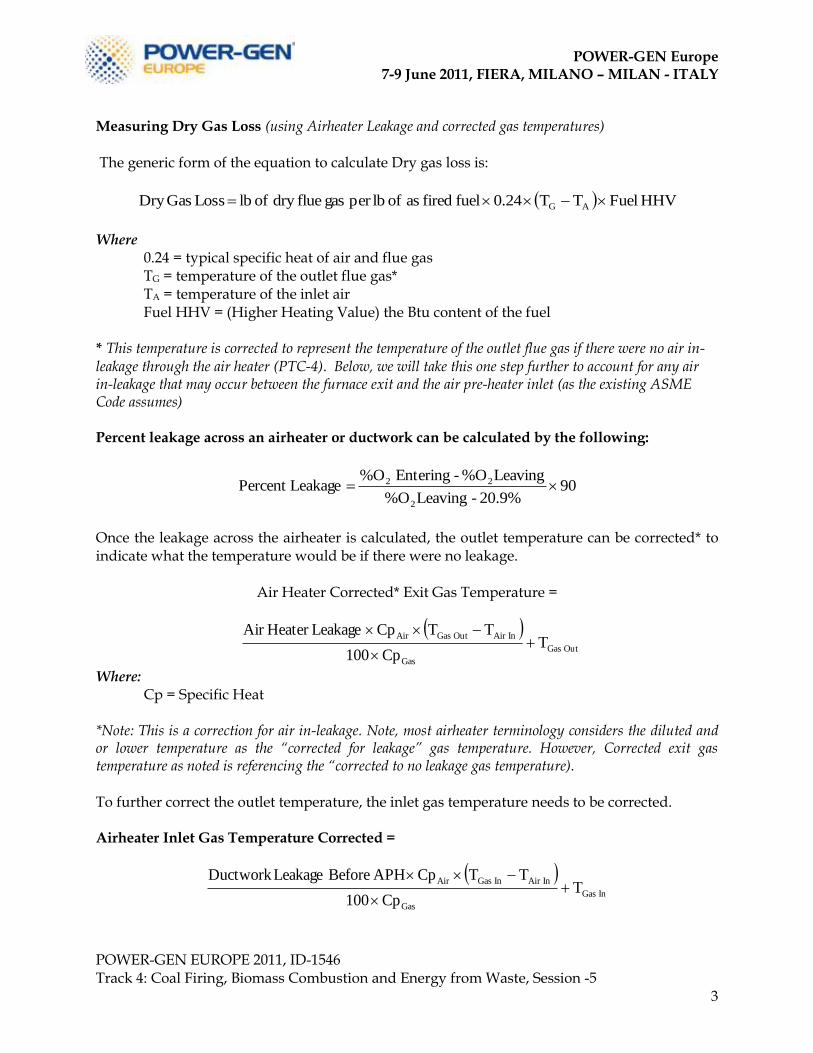
Measuring Dry Gas Loss (using Airheater Leakage and corrected gas temperatures) The generic form of the equation to calculate Dry gas loss is:
HHV FuelTT0.24fuel fired as of lbper gas fluedry of lb Loss GasDry AG
Where 0.24 = typical specific heat of air and flue gas TG = temperature of the outlet flue gas* TA = temperature of the inlet air
Fuel HHV = (Higher Heating Value) the Btu content of the fuel * This temperature is corrected to represent the temperature of the outlet flue gas if there were no air in-leakage through the air heater (PTC-4). Below, we will take this one step further to account for any air in-leakage that may occur between the furnace exit and the air pre-heater inlet (as the existing ASME Code assumes) Percent leakage across an airheater or ductwork can be calculated by the following:
9020.9%-Leaving%O
Leaving%O-Entering %O LeakagePercent
2
22
Once the leakage across the airheater is calculated, the outlet temperature can be corrected* to indicate what the temperature would be if there were no leakage.
Air Heater Corrected* Exit Gas Temperature =
OutGas
Gas
InAirOutGasAirT
Cp100
TTCpLeakageHeater Air
Where: Cp = Specific Heat *Note: This is a correction for air in-leakage. Note, most airheater terminology considers the diluted and or lower temperature as the “corrected for leakage” gas temperature. However, Corrected exit gas temperature as noted is referencing the “corrected to no leakage gas temperature). To further correct the outlet temperature, the inlet gas temperature needs to be corrected. Airheater Inlet Gas Temperature Corrected =
InGas
Gas
InAirInGasAirT
Cp100
TTCpAPH Before LeakageDuctwork
POWER-GEN Europe 7-9 June 2011, FIERA, MILANO – MILAN - ITALY
POWER-GEN EUROPE 2011, ID-1546 Track 4: Coal Firing, Biomass Combustion and Energy from Waste, Session -5
4
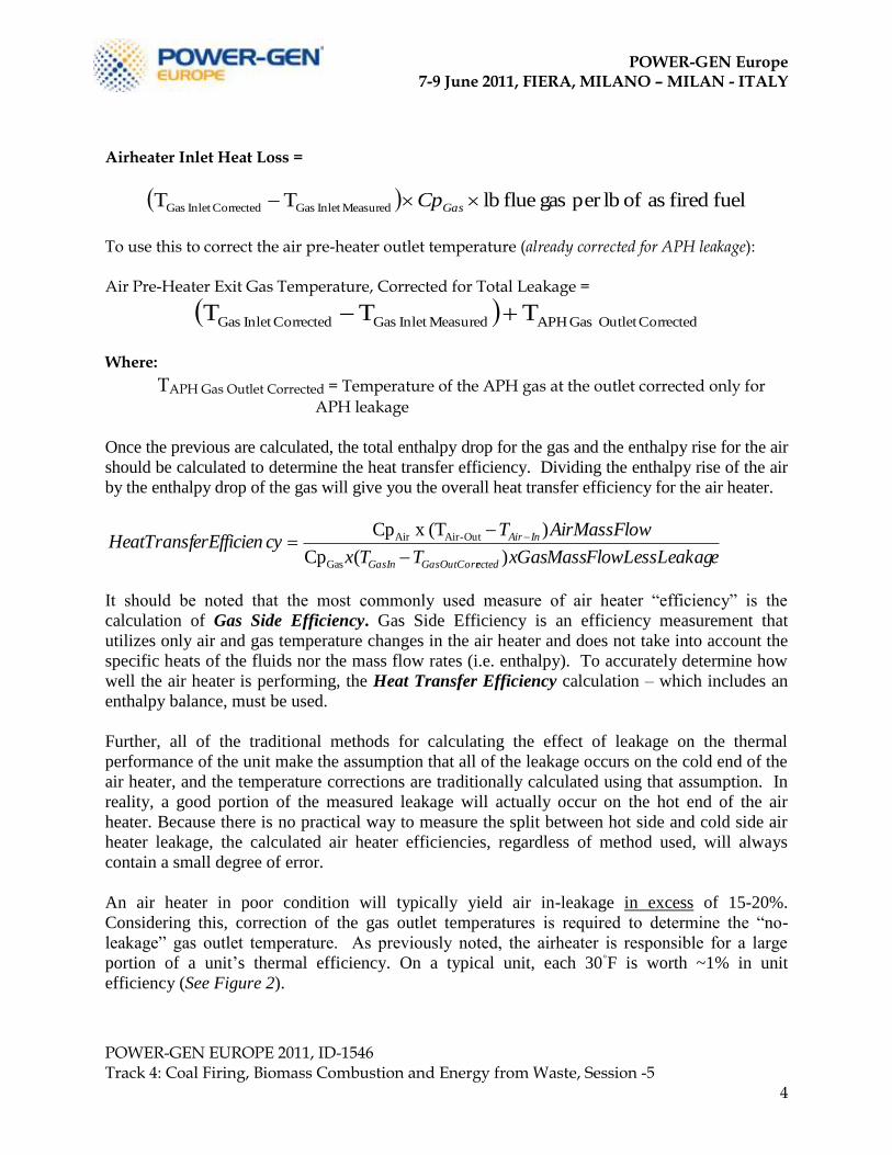
Airheater Inlet Heat Loss =
fuel fired as of lbper gas flue lbTT MeasuredInlet GasCorrectedInlet Gas GasCp
To use this to correct the air pre-heater outlet temperature (already corrected for APH leakage): Air Pre-Heater Exit Gas Temperature, Corrected for Total Leakage =
CorrectedOutlet Gas APHMeasuredInlet GasCorrectedInlet Gas T TT
Where:
TAPH Gas Outlet Corrected = Temperature of the APH gas at the outlet corrected only for
APH leakage
Once the previous are calculated, the total enthalpy drop for the gas and the enthalpy rise for the air
should be calculated to determine the heat transfer efficiency. Dividing the enthalpy rise of the air
by the enthalpy drop of the gas will give you the overall heat transfer efficiency for the air heater.
eLessLeakagFlowMassxGasTTx
wAirMassFloTcyerEfficienHeatTransf
ectedGasOutCorrGasIn
InAir
)(Cp
)(T x Cp
Gas
Out-AirAir
It should be noted that the most commonly used measure of air heater “efficiency” is the
calculation of Gas Side Efficiency. Gas Side Efficiency is an efficiency measurement that
utilizes only air and gas temperature changes in the air heater and does not take into account the
specific heats of the fluids nor the mass flow rates (i.e. enthalpy). To accurately determine how
well the air heater is performing, the Heat Transfer Efficiency calculation – which includes an
enthalpy balance, must be used.
Further, all of the traditional methods for calculating the effect of leakage on the thermal
performance of the unit make the assumption that all of the leakage occurs on the cold end of the
air heater, and the temperature corrections are traditionally calculated using that assumption. In
reality, a good portion of the measured leakage will actually occur on the hot end of the air
heater. Because there is no practical way to measure the split between hot side and cold side air
heater leakage, the calculated air heater efficiencies, regardless of method used, will always
contain a small degree of error.
An air heater in poor condition will typically yield air in-leakage in excess of 15-20%.
Considering this, correction of the gas outlet temperatures is required to determine the “no-
leakage” gas outlet temperature. As previously noted, the airheater is responsible for a large
portion of a unit‟s thermal efficiency. On a typical unit, each 30◦F is worth ~1% in unit
efficiency (See Figure 2).
POWER-GEN Europe 7-9 June 2011, FIERA, MILANO – MILAN - ITALY
POWER-GEN EUROPE 2011, ID-1546 Track 4: Coal Firing, Biomass Combustion and Energy from Waste, Session -5
5
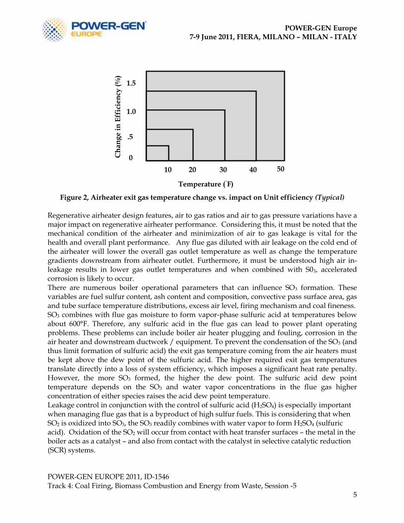
Figure 2, Airheater exit gas temperature change vs. impact on Unit efficiency (Typical)
Regenerative airheater design features, air to gas ratios and air to gas pressure variations have a major impact on regenerative airheater performance. Considering this, it must be noted that the mechanical condition of the airheater and minimization of air to gas leakage is vital for the health and overall plant performance. Any flue gas diluted with air leakage on the cold end of the airheater will lower the overall gas outlet temperature as well as change the temperature gradients downstream from airheater outlet. Furthermore, it must be understood high air in-leakage results in lower gas outlet temperatures and when combined with S03, accelerated corrosion is likely to occur. There are numerous boiler operational parameters that can influence SO3 formation. These variables are fuel sulfur content, ash content and composition, convective pass surface area, gas and tube surface temperature distributions, excess air level, firing mechanism and coal fineness. SO3 combines with flue gas moisture to form vapor-phase sulfuric acid at temperatures below about 600°F. Therefore, any sulfuric acid in the flue gas can lead to power plant operating problems. These problems can include boiler air heater plugging and fouling, corrosion in the air heater and downstream ductwork / equipment. To prevent the condensation of the SO3 (and thus limit formation of sulfuric acid) the exit gas temperature coming from the air heaters must be kept above the dew point of the sulfuric acid. The higher required exit gas temperatures translate directly into a loss of system efficiency, which imposes a significant heat rate penalty. However, the more SO3 formed, the higher the dew point. The sulfuric acid dew point temperature depends on the SO3 and water vapor concentrations in the flue gas higher concentration of either species raises the acid dew point temperature. Leakage control in conjunction with the control of sulfuric acid (H2SO4) is especially important when managing flue gas that is a byproduct of high sulfur fuels. This is considering that when SO2 is oxidized into SO3, the SO3 readily combines with water vapor to form H2SO4 (sulfuric acid). Oxidation of the SO2 will occur from contact with heat transfer surfaces – the metal in the boiler acts as a catalyst – and also from contact with the catalyst in selective catalytic reduction (SCR) systems.
1.5
1.0
0
.5
40 30 20 10
Temperature (◦F)
Ch
an
ge
in
Eff
icie
ncy
(%
)
50
POWER-GEN Europe 7-9 June 2011, FIERA, MILANO – MILAN - ITALY
POWER-GEN EUROPE 2011, ID-1546 Track 4: Coal Firing, Biomass Combustion and Energy from Waste, Session -5
6
While a significant portion of the SO3 will condense on ash particles and be collected along with the fly ash, the non-condensed SO3 can have significant side effects. Excess SO3 leaving the stack can result in a noticeable “blue plume”, which consists primarily of sulfuric acid that has condensed into tiny droplets. Those same droplets may also condense on the cold end of the airheater, or in the downstream ductwork causing corrosion and plugging. In addition, excess SO3 can combine with ammonia slip from an SCR system to form ammonium bisulfate (ABS) which has a notorious reputation for plugging air heater heat transfer element. Essentially, the excess ammonia combines with excess SO3 and water vapor which starts to condense on the air heater element surfaces at temperatures below about 450◦F (230◦C).
NH3+SO
3 +H
2O →NH
4HSO
4
This ABS plugging also impacts the distribution of the air and flue gas while also elevating air to gas differentials and leakage (as a result of the elevated pressure drop across the airheater).
In an effort to remove excess SO3, dry powder or water slurry mixes of alkaline sorbents (ie. hydrated lime, limestone, magnesium oxide, sodium bisulfate and Trona) are sometimes injected upstream or downstream of regenerative airheaters. While these chemicals are quite effective in adsorbing excess SO3 and reducing blue plume and corrosion, the effect of these sorbent on the air heater and its operation are still being evaluated. As a hypothetical example, if injection of a sorbent downstream of the air heater would require an elevated gas outlet temperature for maximum effectiveness, there it would be a boiler efficiency penalty associated with the reduced air heater efficiency that would be needed to provide the elevated temperature. However, it might also be possible to achieve the required elevated temperature without a heat rate penalty by simply reducing air heater leakage – thereby reducing the dilution air which acts to cool the gasses downstream of the air heater.
Considering these challenges, in conjunction with fuel changes or the modernization and
refurbishment of aging units, a thorough performance evaluation of a utility boiler and regenerative
airheater is crucial. This is especially true when taking into account reliability and performance of a
regenerative airheater
Advancements today demand increased focus on the operational and performance variables as well as the mechanical design considerations before applying refurbishment to the heating element or sealing solution on a regenerative airheater. Furthermore, it’s absolutely imperative that the proper materials used in a specification match the process and operational requirements. As a pre-requisite to any advancement with Regenerative Airheater technologies, fundamental and current performance values must be assessed.
POWER-GEN Europe 7-9 June 2011, FIERA, MILANO – MILAN - ITALY
POWER-GEN EUROPE 2011, ID-1546 Track 4: Coal Firing, Biomass Combustion and Energy from Waste, Session -5
7
Some of the operational variables that must be considered are as follows:
Thermal Efficiency
Fuel Analysis (S, N, H2O)
Mineral Ash Analyses
Air Pollution Control (APC) equipment SNCR or SCR Performance (NH
3 Slip)
Sorbent Injections (upstream and downstream of the airheater) APC equipment specifications downstream of the Airheater
SO3
Flue Gas distribution
Velocity and temperature gradients
Flue Gas volume
In addition to the previous, some air heater specific variables that must also be considered are as follows:
Hot End
Intermediate | Cold-End
1. Incoming gas temperature 2. Upstream Air in-leakage 3. Hot end differential Pressure
(air / gas) 4. Incoming flue gas volume and
velocity 5. Gas Inlet Temperature 6. Wind box to Furnace Differential 7. Element Design, Gauge, Weight,
Depth 8. Incoming flue gas oxygen (%)
1. Average cold-end operating temperature 2. Desired flue gas exit temperature
(Corrected for Leakage) 3. Cold end differential pressure (air / gas) 4. Inlet air Temperature 5. Element Design, Gauge, Weight, Depth 6. Exiting flue gas oxygen
Whether you are referencing burner performance, boiler performance, airheater performance and/or the APC equipment, all of these components are influenced by their inputs with regard to their operational efficiency. Variables such as the airheater gas outlet temperatures and velocity gradients, leakage/mass flow, coal fineness, sorbent particle sizing & distribution, excess air setting, calcium-to SO3 molar ratio, ash content and ash resistivity can have a significant impact on the air pollution control equipment. Considering the previous, when evaluating the basic flow paths of a regenerative airheater (figure 3), it’s important that the comprehensive inter-relationships of all the previously noted variables be considered.
POWER-GEN Europe 7-9 June 2011, FIERA, MILANO – MILAN - ITALY
POWER-GEN EUROPE 2011, ID-1546 Track 4: Coal Firing, Biomass Combustion and Energy from Waste, Session -5
8
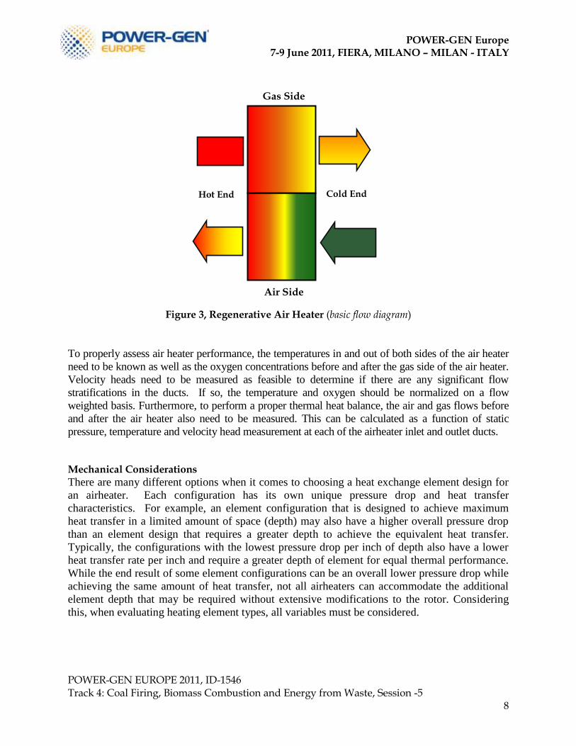
Figure 3, Regenerative Air Heater (basic flow diagram)
To properly assess air heater performance, the temperatures in and out of both sides of the air heater
need to be known as well as the oxygen concentrations before and after the gas side of the air heater.
Velocity heads need to be measured as feasible to determine if there are any significant flow
stratifications in the ducts. If so, the temperature and oxygen should be normalized on a flow
weighted basis. Furthermore, to perform a proper thermal heat balance, the air and gas flows before
and after the air heater also need to be measured. This can be calculated as a function of static
pressure, temperature and velocity head measurement at each of the airheater inlet and outlet ducts. Mechanical Considerations
There are many different options when it comes to choosing a heat exchange element design for
an airheater. Each configuration has its own unique pressure drop and heat transfer
characteristics. For example, an element configuration that is designed to achieve maximum
heat transfer in a limited amount of space (depth) may also have a higher overall pressure drop
than an element design that requires a greater depth to achieve the equivalent heat transfer.
Typically, the configurations with the lowest pressure drop per inch of depth also have a lower
heat transfer rate per inch and require a greater depth of element for equal thermal performance.
While the end result of some element configurations can be an overall lower pressure drop while
achieving the same amount of heat transfer, not all airheaters can accommodate the additional
element depth that may be required without extensive modifications to the rotor. Considering
this, when evaluating heating element types, all variables must be considered.
Air Side
Gas Side
Hot End
Cold End
POWER-GEN Europe 7-9 June 2011, FIERA, MILANO – MILAN - ITALY
POWER-GEN EUROPE 2011, ID-1546 Track 4: Coal Firing, Biomass Combustion and Energy from Waste, Session -5
9
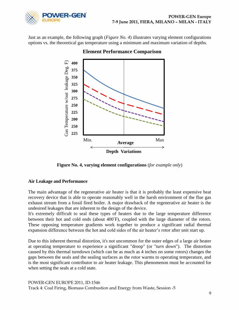
Just as an example, the following graph (Figure No. 4) illustrates varying element configurations
options vs. the theoretical gas temperature using a minimum and maximum variation of depths.
Gas
Tem
per
atu
re w
/ou
t l
eak
age
Deg
. F
)
Element Performance Comparison
200
225
250
275
300
225
250
375
400
325
350
Depth Variations
Min. Max Average
Figure No. 4, varying element configurations (for example only)
Air Leakage and Performance
The main advantage of the regenerative air heater is that it is probably the least expensive heat
recovery device that is able to operate reasonably well in the harsh environment of the flue gas
exhaust stream from a fossil fired boiler. A major drawback of the regenerative air heater is the
undesired leakages that are inherent to the design of the device.
It's extremely difficult to seal these types of heaters due to the large temperature difference
between their hot and cold ends (about 400◦F), coupled with the large diameter of the rotors.
These opposing temperature gradients work together to produce a significant radial thermal
expansion difference between the hot and cold sides of the air heater‟s rotor after unit start up.
Due to this inherent thermal distortion, it's not uncommon for the outer edges of a large air heater
at operating temperature to experience a significant "droop" (or "turn down"). The distortion
caused by this thermal turndown (which can be as much as 4 inches on some rotors) changes the
gaps between the seals and the sealing surfaces as the rotor warms to operating temperature, and
is the most significant contributor to air heater leakage. This phenomenon must be accounted for
when setting the seals at a cold state.
POWER-GEN Europe 7-9 June 2011, FIERA, MILANO – MILAN - ITALY
POWER-GEN EUROPE 2011, ID-1546 Track 4: Coal Firing, Biomass Combustion and Energy from Waste, Session -5
10
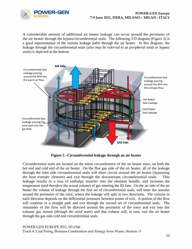
A considerable amount of additional air heater leakage can occur around the perimeter of
the air heater through the bypass/circumferential seals. The following 3-D diagram (Figure 5) is
a good representation of the various leakage paths through the air heater. In this diagram, the
leakage through the circumferential seals (also may be referred to as peripheral seals or bypass
seals) is depicted at the bottom.
Figure 5 –Circumferential leakage through an air heater
Circumferential seals are located on the entire circumference of the air heater rotor, on both the
hot end and cold end of the air heater. On the flue gas side of the air heater, all of the leakage
through the inlet side circumferential seals will short circuit around the air heater (bypassing
the heat transfer element) and exit through the downstream circumferential seals. This
leakage results in a loss of enthalpy transfer into the element bundle, and increases the
temperature (and therefore the actual volume) of gas entering the ID fans. On the air side of the air
heater the volume of leakage through the first set of circumferential seals, will enter the annulus
around the perimeter of the rotor, where the leakage will split in two directions. The volume in
each direction depends on the differential pressures between points of exit. A portion of the flow
will continue in a straight path and exit through the second set of circumferential seals. The
remainder of the flow will be directed around the perimeter of the rotor and exit into the
exhaust gas stream (through the axial seals) and that volume will, in turn, exit the air heater
through the gas side-cold end circumferential seals.
Circumferential Seal Leakage passing the axial seals into the gas flow
Circumferential Seal Leakage passing around the APH into the warm air flow
Circumferential Seal Leakage passing around the APH into the cold gas flow
Hot Radial Seal Leakage
Cold Radial Seal Leakage
GAS Side
AIR Side
POWER-GEN Europe 7-9 June 2011, FIERA, MILANO – MILAN - ITALY
POWER-GEN EUROPE 2011, ID-1546 Track 4: Coal Firing, Biomass Combustion and Energy from Waste, Session -5
11
Radial seal leakage is expressed as a percentage and basically represents the percentage of the
gas flow downstream from the airheater that is the result of the mass of inlet air that leaks
through the airheater seals into the gas outlet stream. It is the experience of the authors is such
that radial leakage rates over 40% have been measured in some air heaters. Furthermore, leakage
rates around15% to 20% are often accepted as a “normal” condition, especially in older air
heaters that have experienced physical distortion, wear, and erosion over time. Leakage at this
level places a significant extra burden on the boiler fans in order to move gas and air that serves
no useful purpose. The burden placed on the fans is often exacerbated by the fact that, in many
plants, changes in fuels and operating conditions over the years have resulted in induced draft
fans operating at near capacity. Because fans become much less efficient when they operate near
full capacity, a 1% increase in fan volume can actually result in as much as a 3% increase in
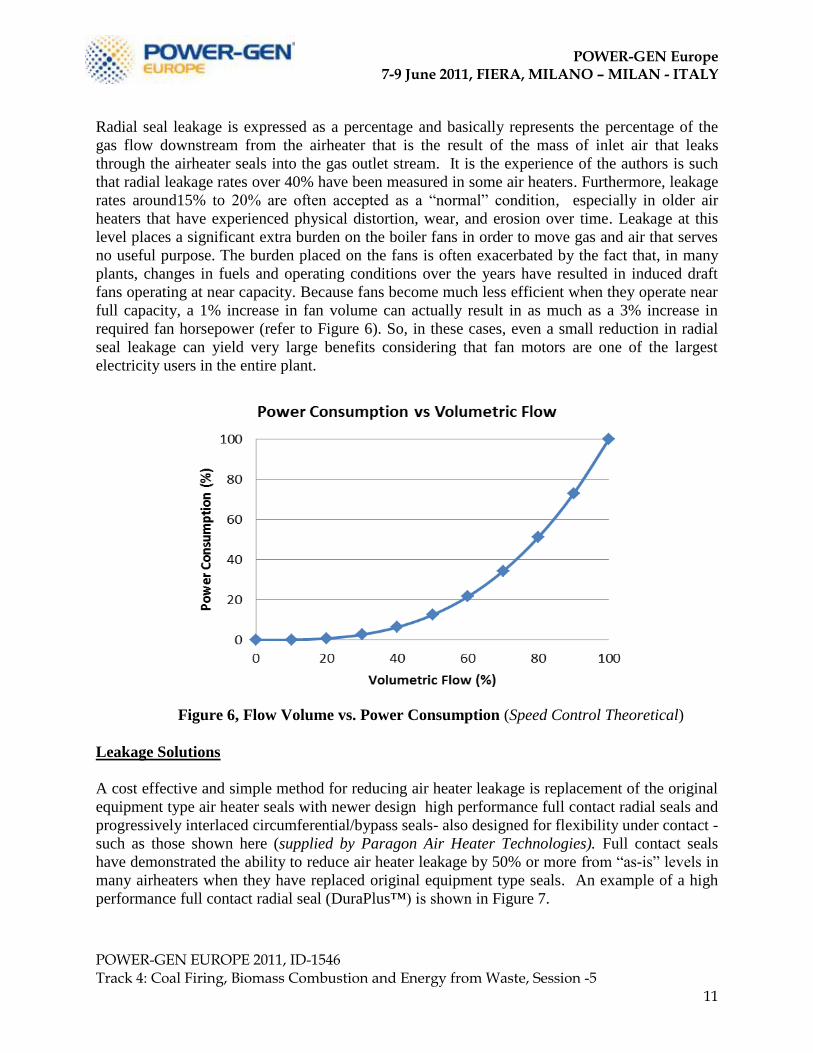
required fan horsepower (refer to Figure 6). So, in these cases, even a small reduction in radial
seal leakage can yield very large benefits considering that fan motors are one of the largest
electricity users in the entire plant.
Figure 6, Flow Volume vs. Power Consumption (Speed Control Theoretical)
Leakage Solutions
A cost effective and simple method for reducing air heater leakage is replacement of the original
equipment type air heater seals with newer design high performance full contact radial seals and
progressively interlaced circumferential/bypass seals- also designed for flexibility under contact -
such as those shown here (supplied by Paragon Air Heater Technologies). Full contact seals
have demonstrated the ability to reduce air heater leakage by 50% or more from “as-is” levels in
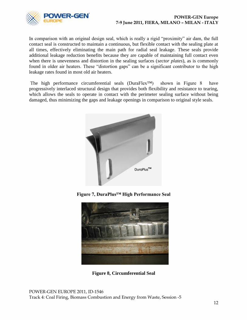
many airheaters when they have replaced original equipment type seals. An example of a high
performance full contact radial seal (DuraPlus™) is shown in Figure 7.
POWER-GEN Europe 7-9 June 2011, FIERA, MILANO – MILAN - ITALY
POWER-GEN EUROPE 2011, ID-1546 Track 4: Coal Firing, Biomass Combustion and Energy from Waste, Session -5
12
In comparison with an original design seal, which is really a rigid “proximity” air dam, the full
contact seal is constructed to maintain a continuous, but flexible contact with the sealing plate at
all times, effectively eliminating the main path for radial seal leakage. These seals provide
additional leakage reduction benefits because they are capable of maintaining full contact even
when there is unevenness and distortion in the sealing surfaces (sector plates), as is commonly
found in older air heaters. These “distortion gaps” can be a significant contributor to the high
leakage rates found in most old air heaters.
The high performance circumferential seals (DuraFlex™) shown in Figure 8 have
progressively interlaced structural design that provides both flexibility and resistance to tearing,
which allows the seals to operate in contact with the perimeter sealing surface without being
damaged, thus minimizing the gaps and leakage openings in comparison to original style seals.
Figure 7, DuraPlus™ High Performance Seal
Figure 8, Circumferential Seal
POWER-GEN Europe 7-9 June 2011, FIERA, MILANO – MILAN - ITALY
POWER-GEN EUROPE 2011, ID-1546 Track 4: Coal Firing, Biomass Combustion and Energy from Waste, Session -5
13
Improved Reliability and Heating Element Considerations
To further pursue innovative advancements in air heater performance, the cold end element
layers of a regenerative airheater can be coated with state of the art enamel that is formulated
with nanoparticle additives that provide unique attributes. This nanotechnology is the result of a
joint 8 year development project by the University of Bologna and SMALTIFLEX S.p.A.,
Modena, Italy, a Paragon Air Heater Technologies partner.
Engineering materials, including coatings and in particular enamel coatings, often have a limited
lifespan due to unavoidable degradation and unexpected damage from stress and strain. In order
to overcome these issues, research in the field of self-healing materials, defined as a „„material
where damage automates a healing response,‟‟ is currently an active field of study. This research
is driven by the possibility that future materials may not have to be replaced, which would result
in cost and efficiency savings in many applications. Vitreous enamel coatings are one of the
materials which benefit from these research activities and are being used for high performance
applications.
Vitreous enamel coating are a special class of ceramic-glass material used as coating for metal
substrate. Vitreous enamel coatings are characterized by high corrosion resistance (that can be 10
times higher than conventional stainless steel) and high value of superficial hardness (from 600
HV to 800 HV), nevertheless they are brittle in nature and spalling phenomena can affect their
in-service performance.
The concept of developing a self-repair enamel coating has been driven by the need for enhanced
mechanical performance when subjected to external loads that can be static or dynamic (fatigue
or impact). Different strategies are being proposed to achieve self-repair effects in case of
mechanically loaded components made by metals, ceramics, polymers, cements and, even more,
composite materials. In case of polymer materials two main strategies have been considered and
developed: one consider the possibility to induce a self-repair mechanism in polymeric matrix
when a polymer chain is broken, a second strategy, inspired by the tissue self-healing capability,
is based on the introduction of an healing agent into the polymeric matrix. In particular, in the
last case, healing agents can be introduced in a polymeric matrix within microcapsules. The
healing agent is released when cracks are able to open such capsules. After doing so, the
interaction between the agent and particles of a catalyst are introduced in the matrix and can give
rise to local polymerisation effects suitable to bond the crack surfaces and stem the crack
propagation [6]. A similar approach has been followed by introducing hollow glass fibres in a
polymer-matrix composite: an agent stored within the hollow fibres outflows where fibres are
broken allowing both damage detection and in situ restoring effects [7,8]. Based on these
principles several materials and coatings have been developed, nevertheless no one of them is a
vitreous material and, in particular, no one of them is a vitreous coating for metal substrate.
Several problems have been accounted and solved to develop a self-repair vitreous material.
Among these problems the most relevant is the intrinsic brittleness of the vitreous matrix. More
than this and considering the particular case of the vitreous enamel coating, the second aspect
that has to be accounted is the coating adhesion to the substrate. These problems have been
overcome by means of a proper combination of different material manipulation at the nanoscale.
In particular the joined research collaboration of SMALTIFLEX with the Bologna University
have determined the means for modification of enamel coatings through the addition of two
metal oxides nanoparticles and one sub-micrometric repairing agent to the enamel material.
POWER-GEN Europe 7-9 June 2011, FIERA, MILANO – MILAN - ITALY
POWER-GEN EUROPE 2011, ID-1546 Track 4: Coal Firing, Biomass Combustion and Energy from Waste, Session -5
14
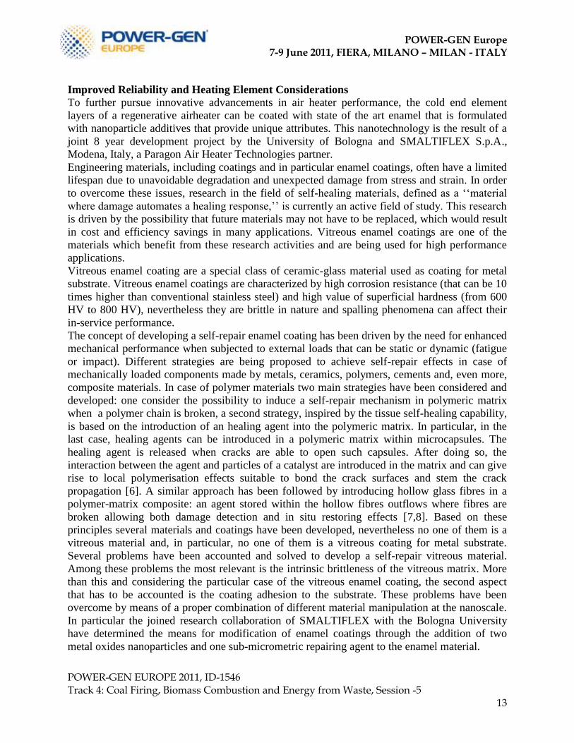
Figure 9 illustrates an example of a stress-strain curve comparing standard and the self-repair
enameled steel commonly used for heating elements. From this diagram it can be seen that the
self-repair enamel exhibits a superior mechanical performance with respect to the stress and the
strain. In particular the research demonstrates that the strain of self-repair enamel is 2.4 times
greater than a standard one and that the stress of self-repair enamel is 2.7 times greater than
standard.
Figure 9: example of stress-strain diagram in the case of standard and self-repair enamel;
and an SEM image of the crack stopping process that characterizes the self-repair enamel.
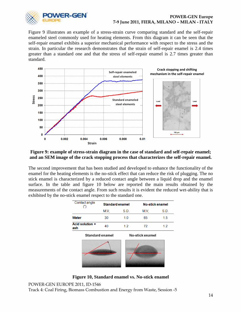
The second improvement that has been studied and developed to enhance the functionality of the
enamel for the heating elements is the no-stick effect that can reduce the risk of plugging. The no
stick enamel is characterized by a reduced contact angle between a liquid drop and the enamel
surface. In the table and figure 10 below are reported the main results obtained by the
measurements of the contact angle. From such results it is evident the reduced wet-ability that is
exhibited by the no-stick enamel respect to the standard one.
Figure 10, Standard enamel vs. No-stick enamel
Crack stopping and shifting mechanism in the self-repair enamel
POWER-GEN Europe 7-9 June 2011, FIERA, MILANO – MILAN - ITALY
POWER-GEN EUROPE 2011, ID-1546 Track 4: Coal Firing, Biomass Combustion and Energy from Waste, Session -5
15
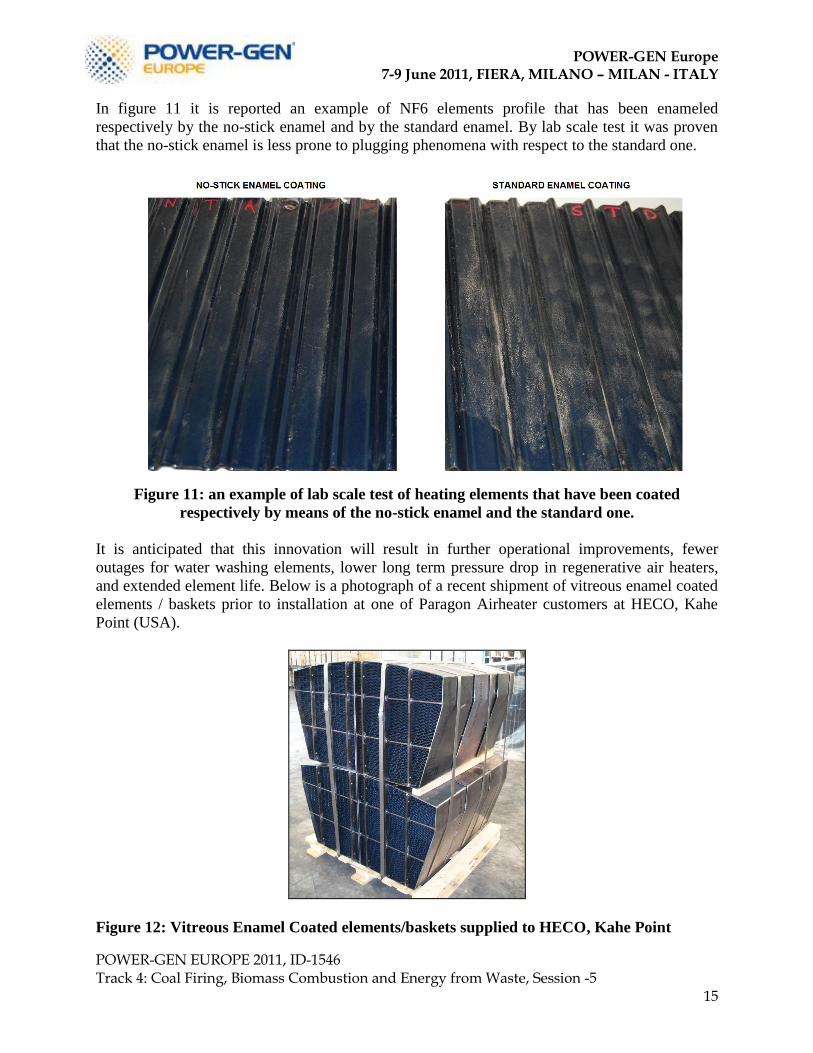
In figure 11 it is reported an example of NF6 elements profile that has been enameled
respectively by the no-stick enamel and by the standard enamel. By lab scale test it was proven
that the no-stick enamel is less prone to plugging phenomena with respect to the standard one.
Figure 11: an example of lab scale test of heating elements that have been coated
respectively by means of the no-stick enamel and the standard one.
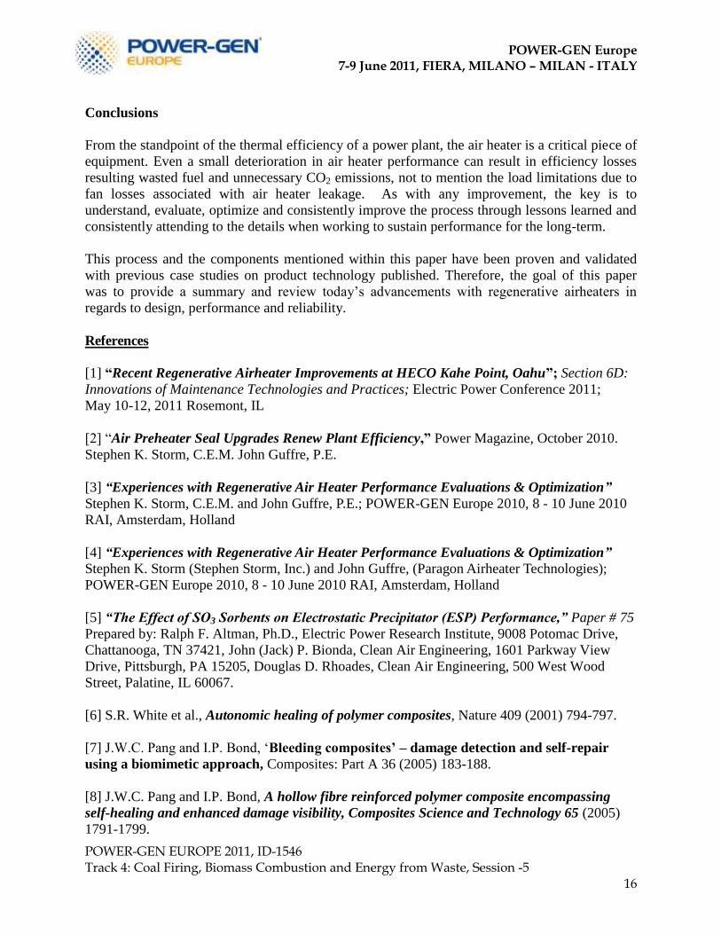
It is anticipated that this innovation will result in further operational improvements, fewer
outages for water washing elements, lower long term pressure drop in regenerative air heaters,
and extended element life. Below is a photograph of a recent shipment of vitreous enamel coated
elements / baskets prior to installation at one of Paragon Airheater customers at HECO, Kahe
Point (USA).
Figure 12: Vitreous Enamel Coated elements/baskets supplied to HECO, Kahe Point
POWER-GEN Europe 7-9 June 2011, FIERA, MILANO – MILAN - ITALY
POWER-GEN EUROPE 2011, ID-1546 Track 4: Coal Firing, Biomass Combustion and Energy from Waste, Session -5
16
Conclusions
From the standpoint of the thermal efficiency of a power plant, the air heater is a critical piece of
equipment. Even a small deterioration in air heater performance can result in efficiency losses
resulting wasted fuel and unnecessary CO2 emissions, not to mention the load limitations due to
fan losses associated with air heater leakage. As with any improvement, the key is to
understand, evaluate, optimize and consistently improve the process through lessons learned and
consistently attending to the details when working to sustain performance for the long-term.
This process and the components mentioned within this paper have been proven and validated
with previous case studies on product technology published. Therefore, the goal of this paper
was to provide a summary and review today‟s advancements with regenerative airheaters in
regards to design, performance and reliability.
References
[1] “Recent Regenerative Airheater Improvements at HECO Kahe Point, Oahu”; Section 6D:
Innovations of Maintenance Technologies and Practices; Electric Power Conference 2011;
May 10-12, 2011 Rosemont, IL
[2] “Air Preheater Seal Upgrades Renew Plant Efficiency,” Power Magazine, October 2010.
Stephen K. Storm, C.E.M. John Guffre, P.E.
[3] “Experiences with Regenerative Air Heater Performance Evaluations & Optimization”
Stephen K. Storm, C.E.M. and John Guffre, P.E.; POWER-GEN Europe 2010, 8 - 10 June 2010
RAI, Amsterdam, Holland
[4] “Experiences with Regenerative Air Heater Performance Evaluations & Optimization”
Stephen K. Storm (Stephen Storm, Inc.) and John Guffre, (Paragon Airheater Technologies);
POWER-GEN Europe 2010, 8 - 10 June 2010 RAI, Amsterdam, Holland
[5] “The Effect of SO3 Sorbents on Electrostatic Precipitator (ESP) Performance,” Paper # 75
Prepared by: Ralph F. Altman, Ph.D., Electric Power Research Institute, 9008 Potomac Drive,
Chattanooga, TN 37421, John (Jack) P. Bionda, Clean Air Engineering, 1601 Parkway View
Drive, Pittsburgh, PA 15205, Douglas D. Rhoades, Clean Air Engineering, 500 West Wood
Street, Palatine, IL 60067.
[6] S.R. White et al., Autonomic healing of polymer composites, Nature 409 (2001) 794-797.
[7] J.W.C. Pang and I.P. Bond, „Bleeding composites’ – damage detection and self-repair
using a biomimetic approach, Composites: Part A 36 (2005) 183-188.
[8] J.W.C. Pang and I.P. Bond, A hollow fibre reinforced polymer composite encompassing
self-healing and enhanced damage visibility, Composites Science and Technology 65 (2005)
1791-1799.