Netzsch Technologies India Private Limited, Chennai, Thermal Analysers
Advanced Water Treatment Technologies – Chennai
Initiatives
Workshop conducted by MoUD, New Delhi
11.03.2011
Chennai Metropolitan Water Supply and
Sewerage Board
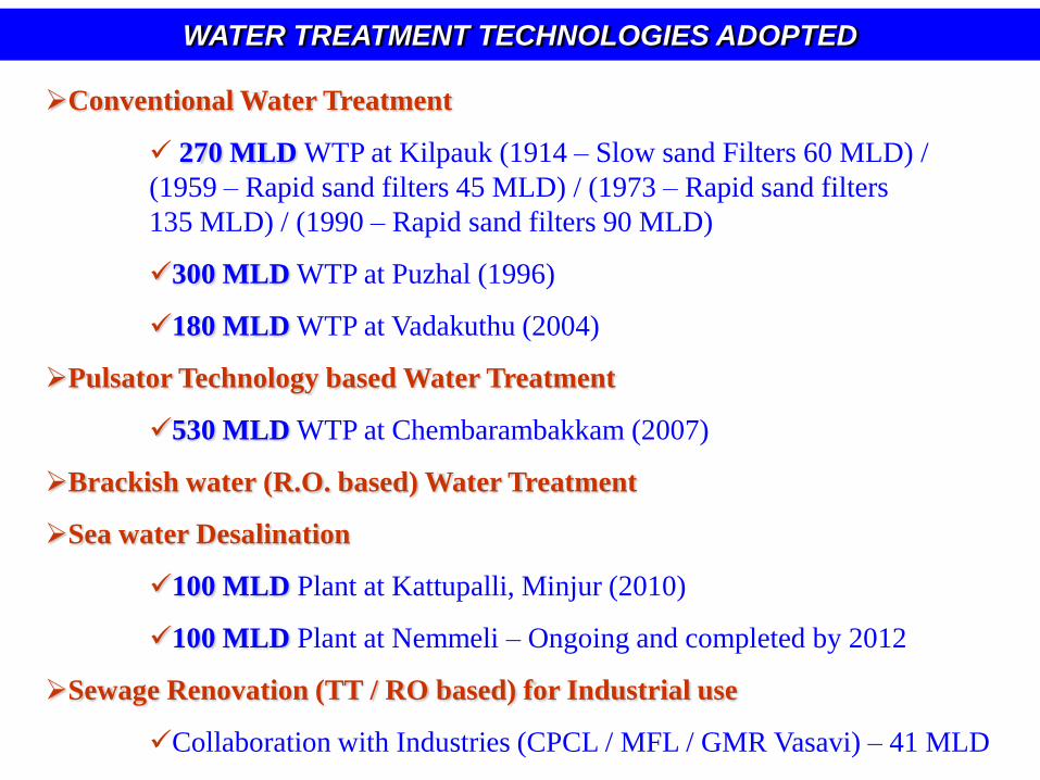
Conventional Water Treatment
270 MLD WTP at Kilpauk (1914 – Slow sand Filters 60 MLD) /
(1959 – Rapid sand filters 45 MLD) / (1973 – Rapid sand filters
135 MLD) / (1990 – Rapid sand filters 90 MLD)
300 MLD WTP at Puzhal (1996)
180 MLD WTP at Vadakuthu (2004)
Pulsator Technology based Water Treatment
530 MLD WTP at Chembarambakkam (2007)
Brackish water (R.O. based) Water Treatment
Sea water Desalination
100 MLD Plant at Kattupalli, Minjur (2010)
100 MLD Plant at Nemmeli – Ongoing and completed by 2012
Sewage Renovation (TT / RO based) for Industrial use
Collaboration with Industries (CPCL / MFL / GMR Vasavi) – 41 MLD
WATER TREATMENT TECHNOLOGIES ADOPTED
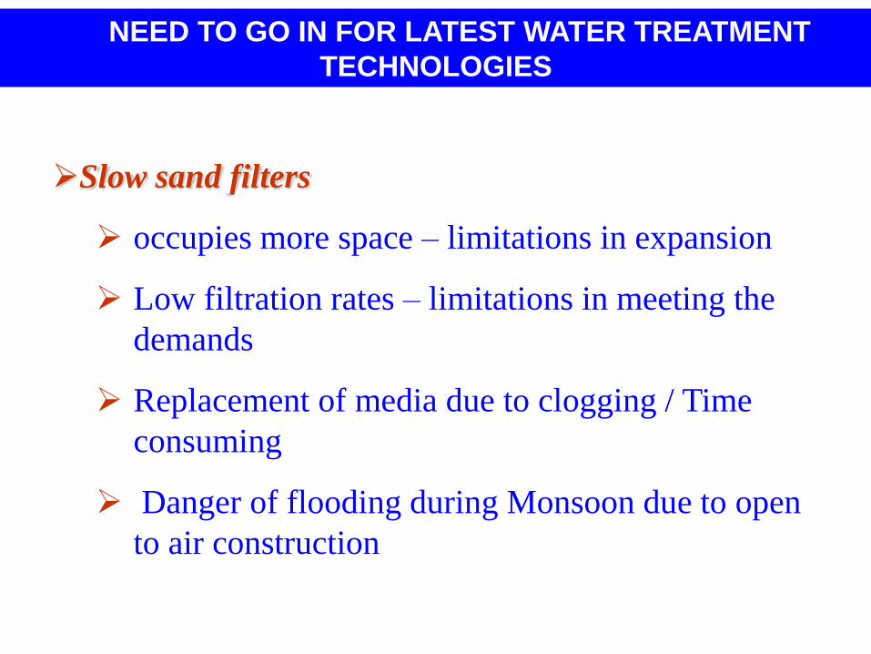
NEED TO GO IN FOR LATEST WATER TREATMENT
TECHNOLOGIES
Slow sand filters
occupies more space – limitations in expansion
Low filtration rates – limitations in meeting the
demands
Replacement of media due to clogging / Time
consuming
Danger of flooding during Monsoon due to open
to air construction
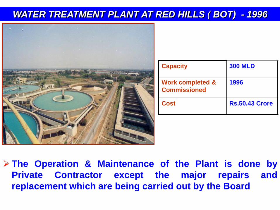
WATER TREATMENT PLANT AT RED HILLS ( BOT) - 1996
The Operation & Maintenance of the Plant is done by
Private Contractor except the major repairs and
replacement which are being carried out by the Board
Capacity 300 MLD
Work completed &
Commissioned
1996
Cost Rs.50.43 Crore
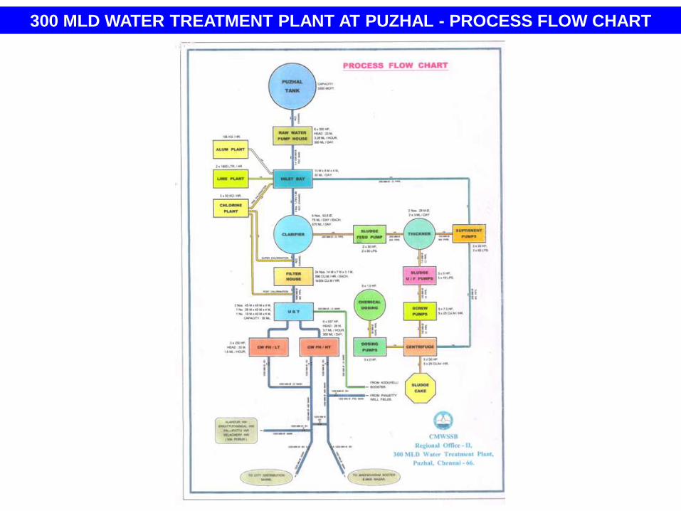
300 MLD WATER TREATMENT PLANT AT PUZHAL - PROCESS FLOW CHART
300 MLD Water Treatment Plant at Puzhal
• Year of Construction - 1996
• Capacity - 300 MLD
• Operation & Maintenance - M/s VA Tech Wabag Ltd
• Period of contract - 3 Years
• Date of commencement - 16.12.2007
• Contract Value - Rs 7,37,55,068/- for 3 years.
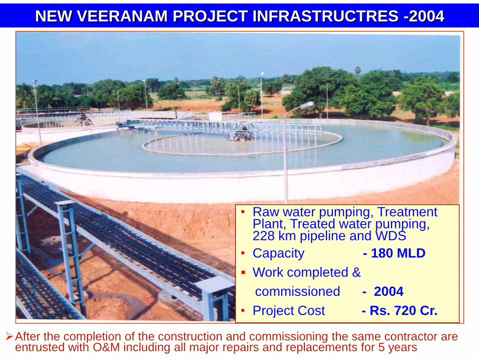
NEW VEERANAM PROJECT INFRASTRUCTRES -2004
• Raw water pumping, Treatment Plant, Treated water pumping, 228 km pipeline and WDS
• Capacity - 180 MLD
Work completed &
commissioned - 2004
• Project Cost - Rs. 720 Cr.
After the completion of the construction and commissioning the same contractor are entrusted with O&M including all major repairs and replacements for 5 years
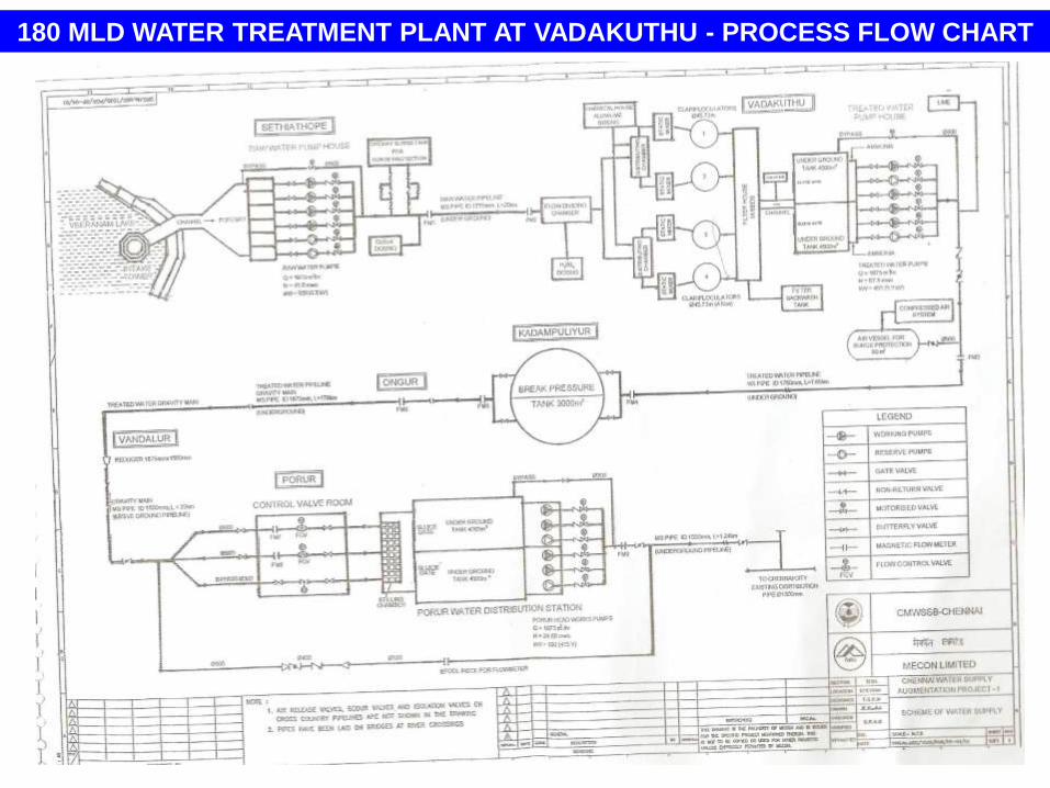
180 MLD WATER TREATMENT PLANT AT VADAKUTHU - PROCESS FLOW CHART
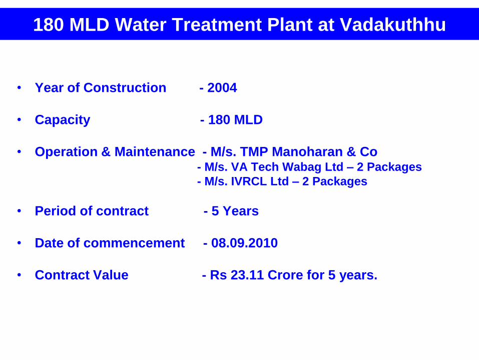
180 MLD Water Treatment Plant at Vadakuthhu
• Year of Construction - 2004
• Capacity - 180 MLD
• Operation & Maintenance - M/s. TMP Manoharan & Co- M/s. VA Tech Wabag Ltd – 2 Packages
- M/s. IVRCL Ltd – 2 Packages
• Period of contract - 5 Years
• Date of commencement - 08.09.2010
• Contract Value - Rs 23.11 Crore for 5 years.
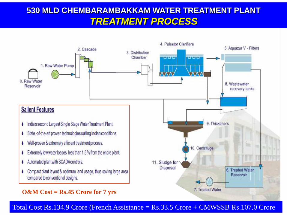
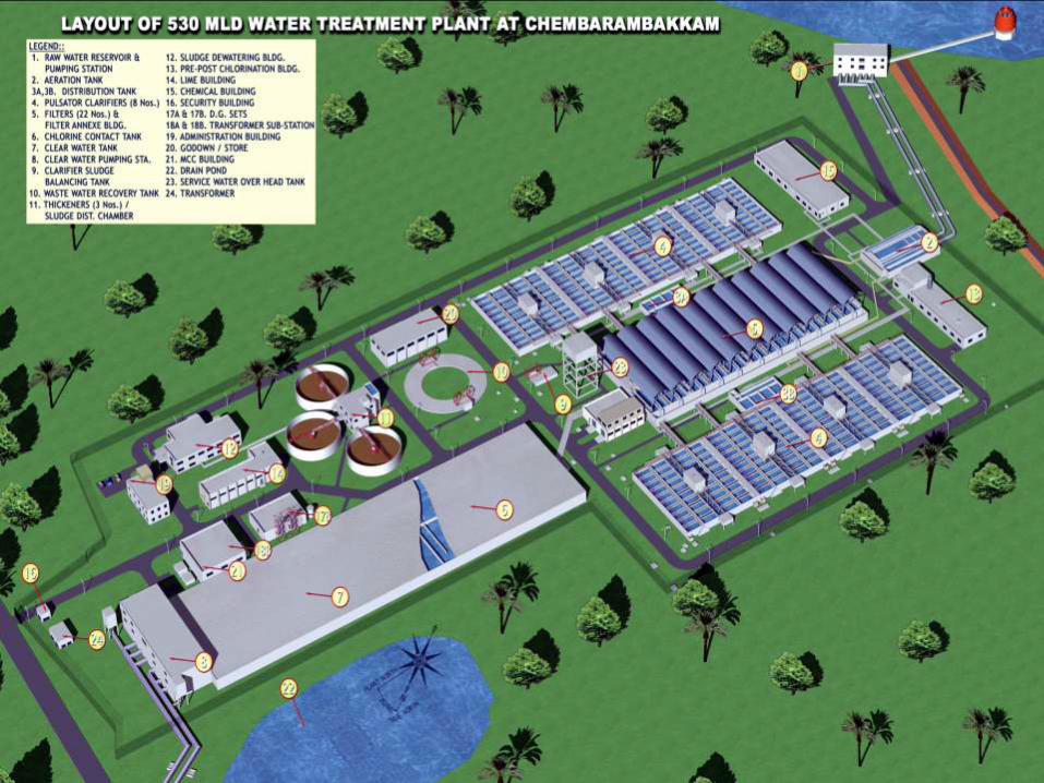
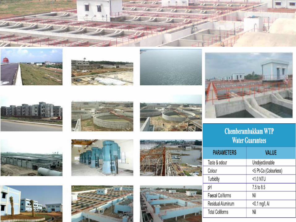
530 MLD CHEMBARAMBAKKAM WATER TREATMENT PLANT
TREATMENT PROCESS
Total Cost Rs.134.9 Crore (French Assistance = Rs.33.5 Crore + CMWSSB Rs.107.0 Crore
O&M Cost = Rs.45 Crore for 7 yrs
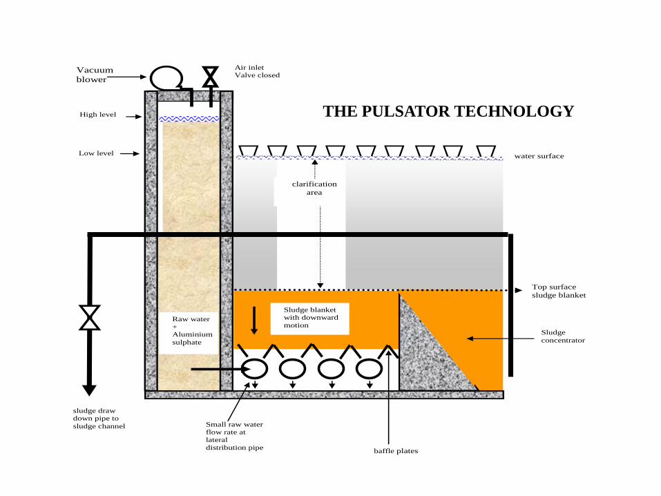
THE PULSATOR TECHNOLOGY
Raw water
+
Aluminium
sulphate
Raw
water + Alum
sulphate
Air inlet
Valve closed
Top surface
sludge blanket
Vacuum
blower
High level
Low level water surface
clarification
area
sludge draw down pipe to
sludge channel
baffle plates
Sludge
concentrator
Sludge blanket
with downward
motion
Small raw water
flow rate at
lateral
distribution pipe
Raw water
+ Aluminium
sulphate
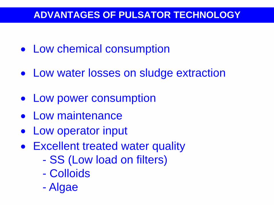
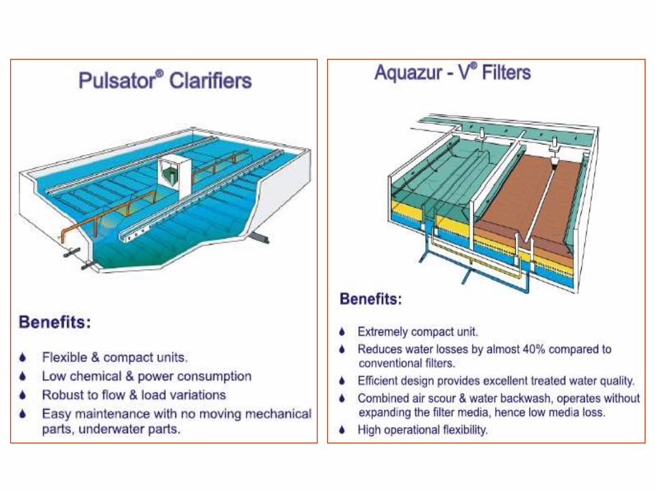
ADVANTAGES OF PULSATOR TECHNOLOGY
Low chemical consumption
Low water losses on sludge extraction
Low power consumption
Low maintenance
Low operator input
Excellent treated water quality
- SS (Low load on filters)
- Colloids
- Algae
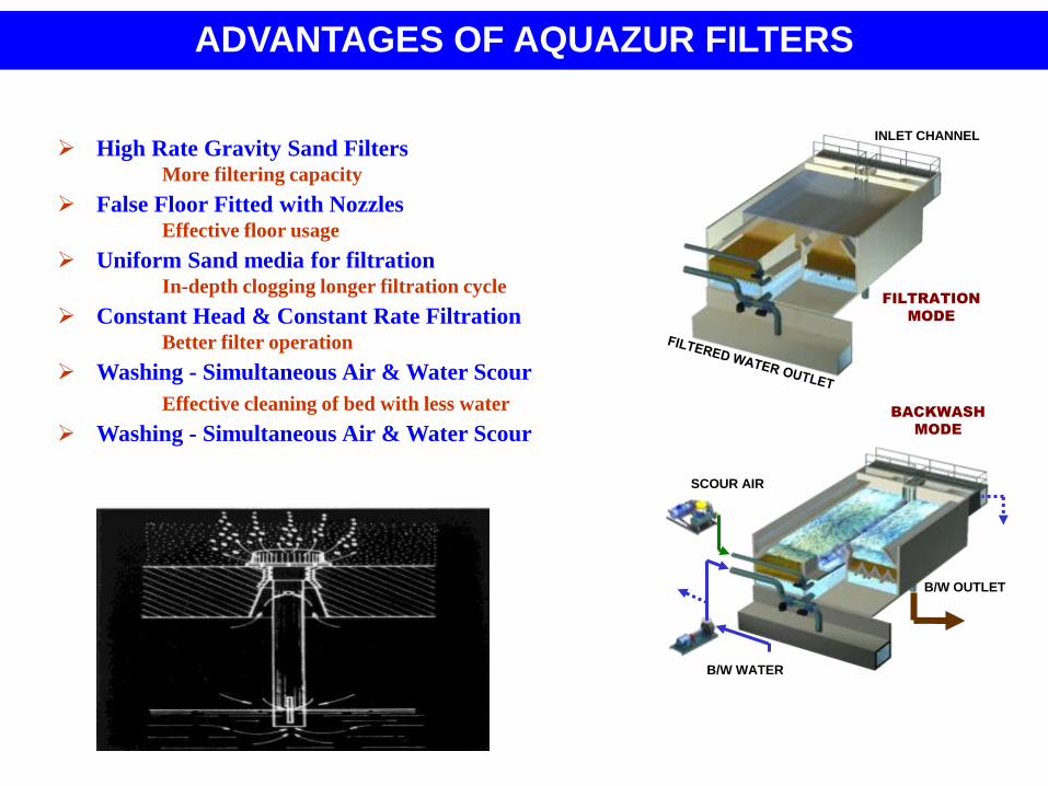
High Rate Gravity Sand FiltersMore filtering capacity
False Floor Fitted with NozzlesEffective floor usage
Uniform Sand media for filtrationIn-depth clogging longer filtration cycle
Constant Head & Constant Rate FiltrationBetter filter operation
Washing - Simultaneous Air & Water Scour
Effective cleaning of bed with less water
Washing - Simultaneous Air & Water Scour
FILTRATION
MODE
BACKWASH
MODE
B/W WATER
SCOUR AIR
B/W OUTLET
INLET CHANNEL
ADVANTAGES OF AQUAZUR FILTERS
BRACKISH WATER R.O.
DESALINATION PLANT
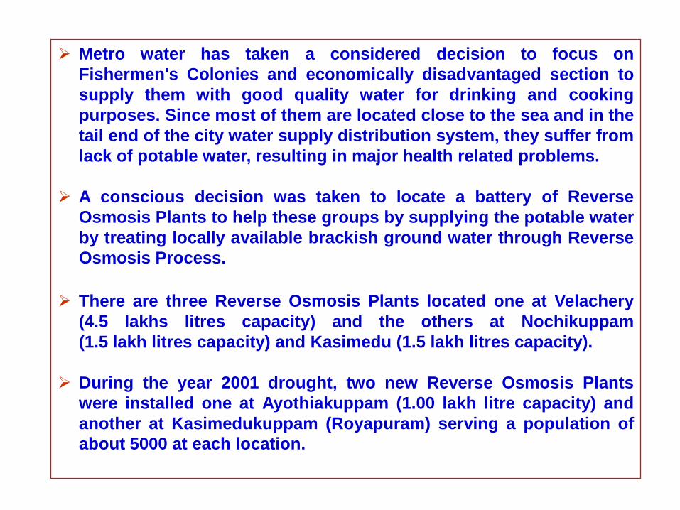
Metro water has taken a considered decision to focus on
Fishermen's Colonies and economically disadvantaged section to
supply them with good quality water for drinking and cooking
purposes. Since most of them are located close to the sea and in the
tail end of the city water supply distribution system, they suffer from
lack of potable water, resulting in major health related problems.
A conscious decision was taken to locate a battery of Reverse
Osmosis Plants to help these groups by supplying the potable water
by treating locally available brackish ground water through Reverse
Osmosis Process.
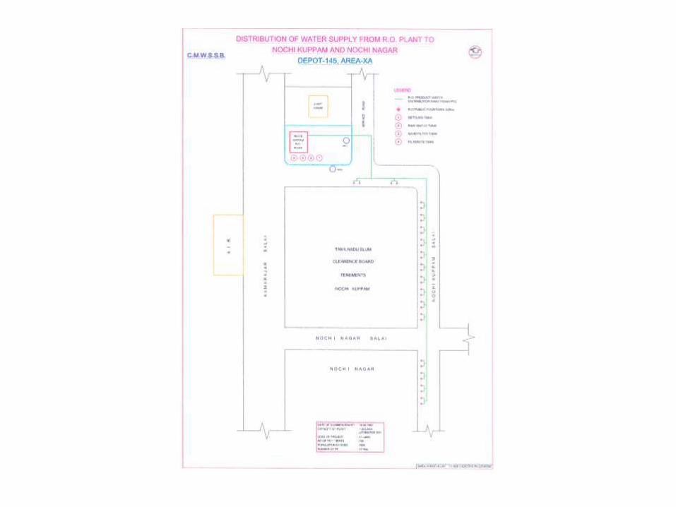
There are three Reverse Osmosis Plants located one at Velachery
(4.5 lakhs litres capacity) and the others at Nochikuppam
(1.5 lakh litres capacity) and Kasimedu (1.5 lakh litres capacity).
During the year 2001 drought, two new Reverse Osmosis Plants
were installed one at Ayothiakuppam (1.00 lakh litre capacity) and
another at Kasimedukuppam (Royapuram) serving a population of
about 5000 at each location.
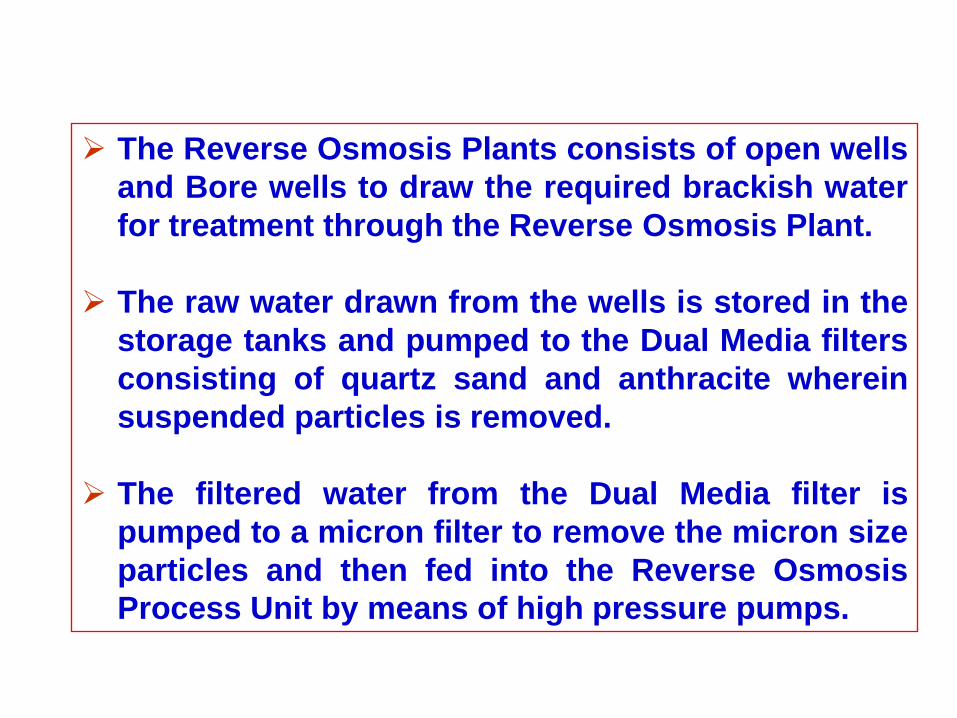
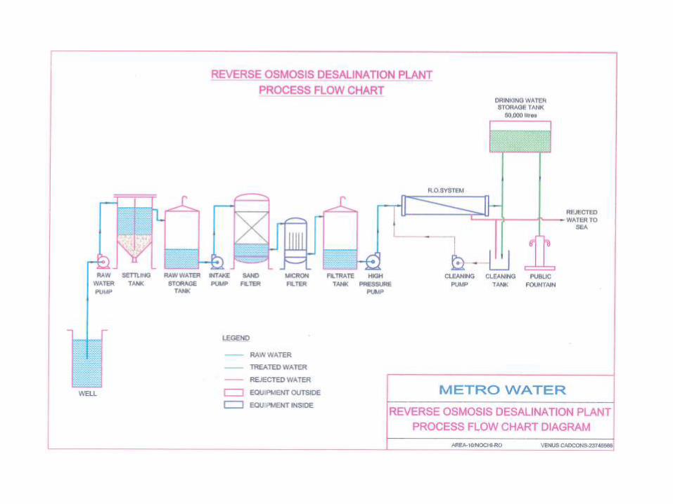
The Reverse Osmosis Plants consists of open wells
and Bore wells to draw the required brackish water
for treatment through the Reverse Osmosis Plant.
The raw water drawn from the wells is stored in the
storage tanks and pumped to the Dual Media filters
consisting of quartz sand and anthracite wherein
suspended particles is removed.
The filtered water from the Dual Media filter is
pumped to a micron filter to remove the micron size
particles and then fed into the Reverse Osmosis
Process Unit by means of high pressure pumps.
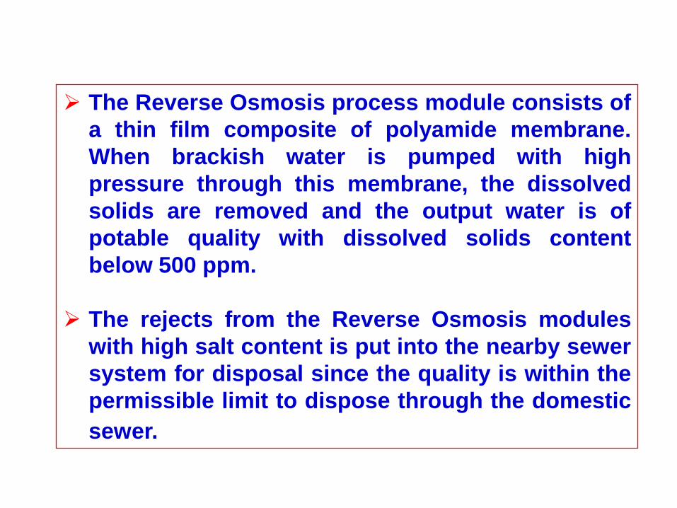
The Reverse Osmosis process module consists of
a thin film composite of polyamide membrane.
When brackish water is pumped with high
pressure through this membrane, the dissolved
solids are removed and the output water is of
potable quality with dissolved solids content
below 500 ppm.
The rejects from the Reverse Osmosis modules
with high salt content is put into the nearby sewer
system for disposal since the quality is within the
permissible limit to dispose through the domestic
sewer.
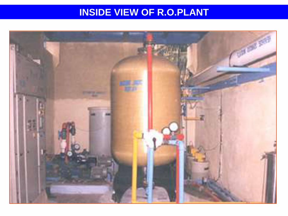
INSIDE VIEW OF R.O.PLANT
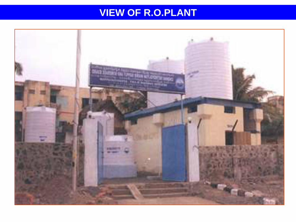
VIEW OF R.O.PLANT
SEA WATER DESALINATION
Even after implementation of the various water supply
augmentation projects and water conservation measures,
there is still a shortfall in meeting the water demand of
Chennai City and adjoining areas.
Further all the existing sources are depend on monsoon
and subject to change in weather patterns and not 100%
reliable and assured supply.
Hence, it is necessary to examine the possibility of
identifying another reliable and assured source of water
supply to bridge the gap between demand and availability.
Need for Alternate Non-Rain dependent Sources
(Sea water Desalination Project)
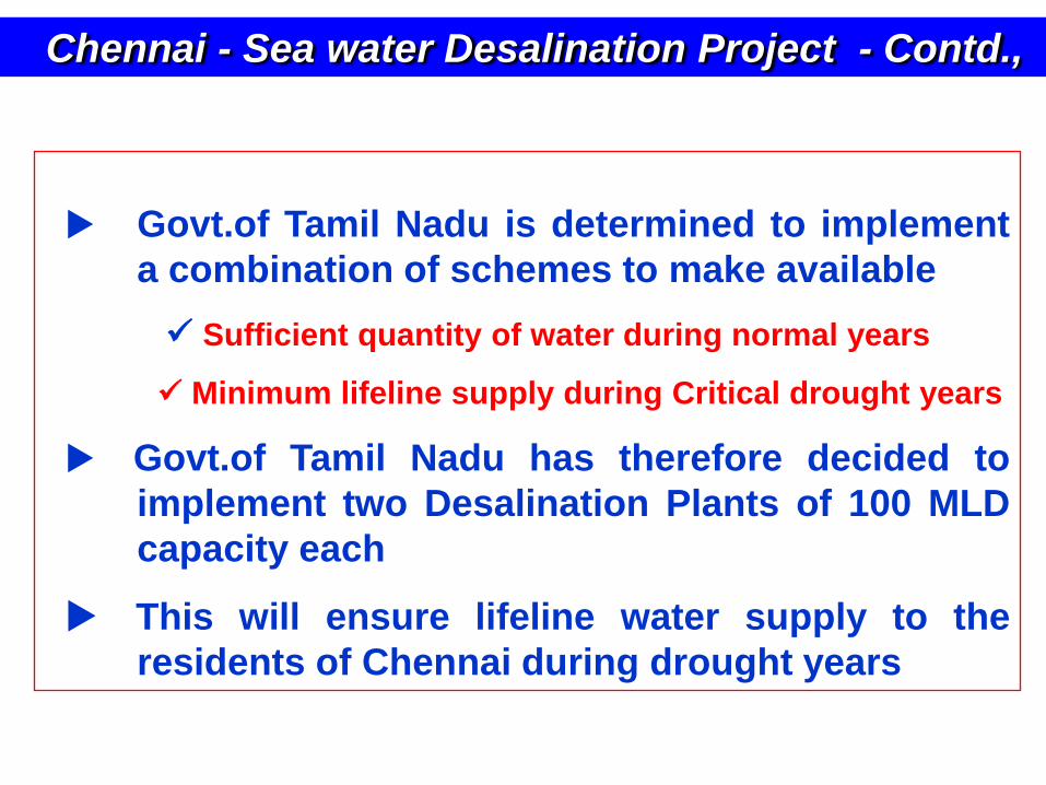
Chennai - Sea water Desalination Project - Contd.,
Govt.of Tamil Nadu is determined to implement
a combination of schemes to make available
Sufficient quantity of water during normal years
Minimum lifeline supply during Critical drought years
Govt.of Tamil Nadu has therefore decided to
implement two Desalination Plants of 100 MLD
capacity each
This will ensure lifeline water supply to the
residents of Chennai during drought years
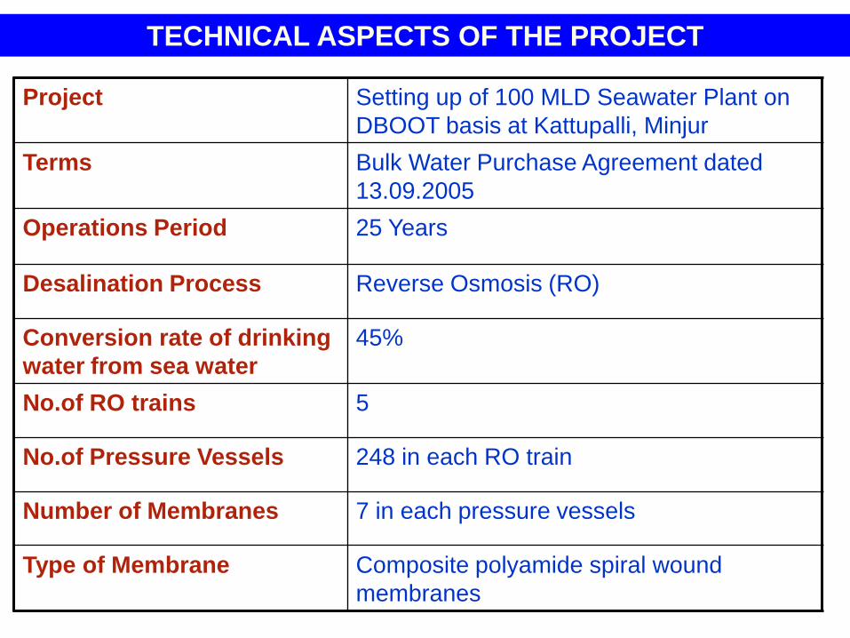
TECHNICAL ASPECTS OF THE PROJECT
Project Setting up of 100 MLD Seawater Plant on
DBOOT basis at Kattupalli, Minjur
Terms Bulk Water Purchase Agreement dated
13.09.2005
Operations Period 25 Years
Desalination Process Reverse Osmosis (RO)
Conversion rate of drinking
water from sea water
45%
No.of RO trains 5
No.of Pressure Vessels 248 in each RO train
Number of Membranes 7 in each pressure vessels
Type of Membrane Composite polyamide spiral wound
membranes
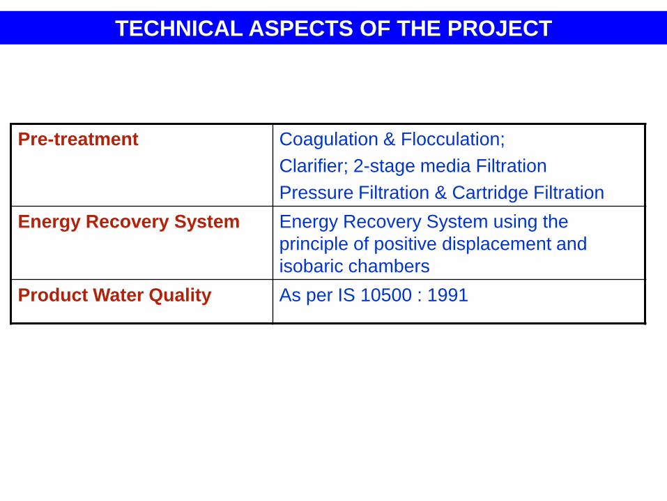
TECHNICAL ASPECTS OF THE PROJECT
Pre-treatment Coagulation & Flocculation;
Clarifier; 2-stage media Filtration
Pressure Filtration & Cartridge Filtration
Energy Recovery System Energy Recovery System using the
principle of positive displacement and
isobaric chambers
Product Water Quality As per IS 10500 : 1991
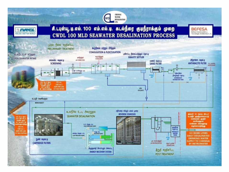
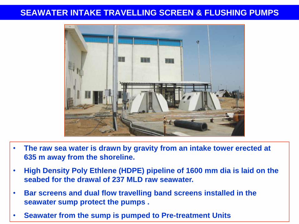
SEAWATER INTAKE TRAVELLING SCREEN & FLUSHING PUMPS
• The raw sea water is drawn by gravity from an intake tower erected at
635 m away from the shoreline.
• High Density Poly Ethlene (HDPE) pipeline of 1600 mm dia is laid on the
seabed for the drawal of 237 MLD raw seawater.
• Bar screens and dual flow travelling band screens installed in the
seawater sump protect the pumps .
• Seawater from the sump is pumped to Pre-treatment Units
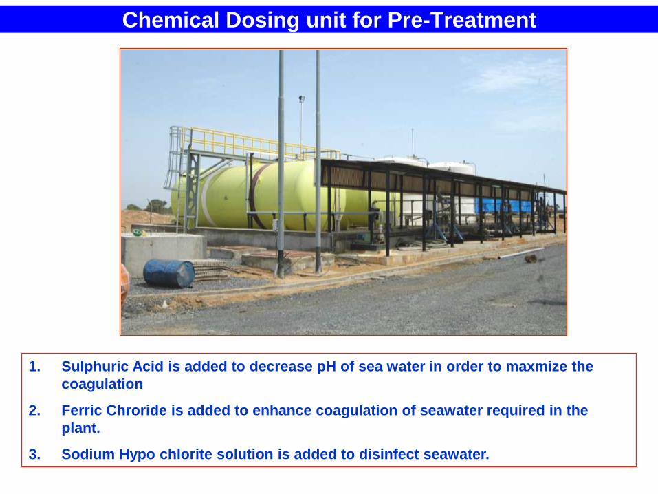
Chemical Dosing unit for Pre-Treatment
1. Sulphuric Acid is added to decrease pH of sea water in order to maxmize the
coagulation
2. Ferric Chroride is added to enhance coagulation of seawater required in the
plant.
3. Sodium Hypo chlorite solution is added to disinfect seawater.
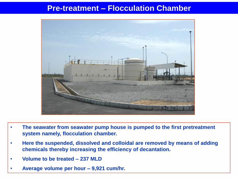
Pre-treatment – Flocculation Chamber
• The seawater from seawater pump house is pumped to the first pretreatment
system namely, flocculation chamber.
• Here the suspended, dissolved and colloidal are removed by means of adding
chemicals thereby increasing the efficiency of decantation.
• Volume to be treated – 237 MLD
• Average volume per hour – 9,921 cum/hr.
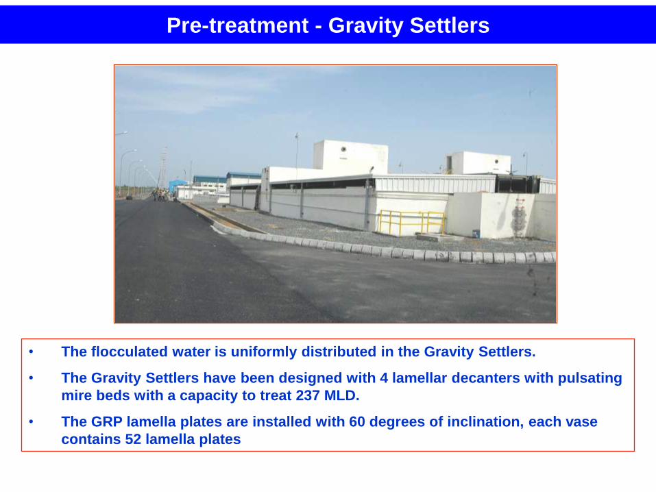
Pre-treatment - Gravity Settlers
• The flocculated water is uniformly distributed in the Gravity Settlers.
• The Gravity Settlers have been designed with 4 lamellar decanters with pulsating
mire beds with a capacity to treat 237 MLD.
• The GRP lamella plates are installed with 60 degrees of inclination, each vase
contains 52 lamella plates
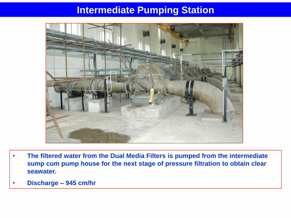
Intermediate Pumping Station
• The filtered water from the Dual Media Filters is pumped from the intermediate
sump cum pump house for the next stage of pressure filtration to obtain clear
seawater.
• Discharge – 945 cm/hr
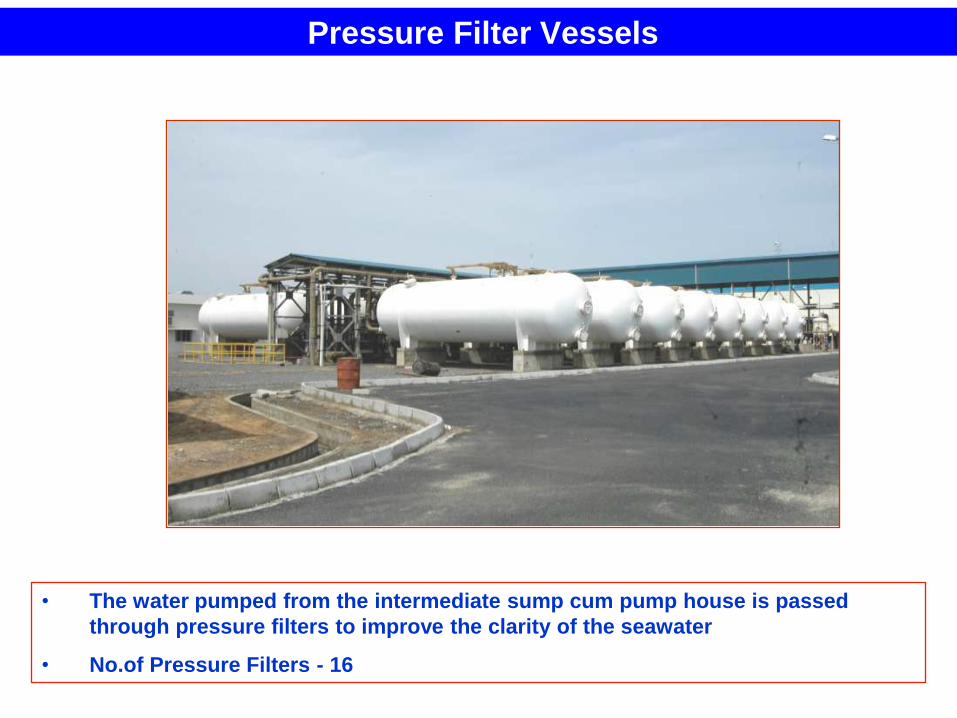
Pressure Filter Vessels
• The water pumped from the intermediate sump cum pump house is passed
through pressure filters to improve the clarity of the seawater
• No.of Pressure Filters - 16
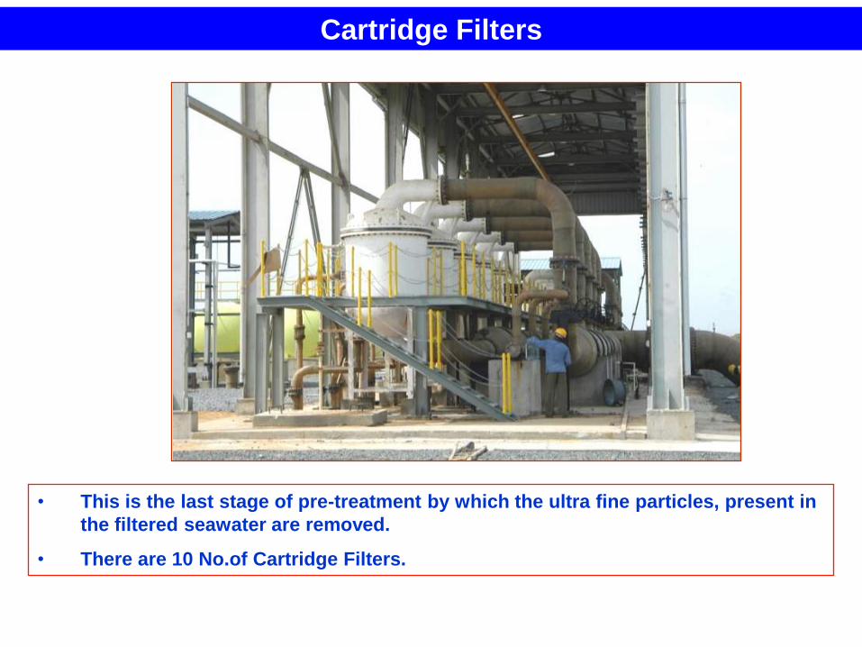
Cartridge Filters
• This is the last stage of pre-treatment by which the ultra fine particles, present in
the filtered seawater are removed.
• There are 10 No.of Cartridge Filters.
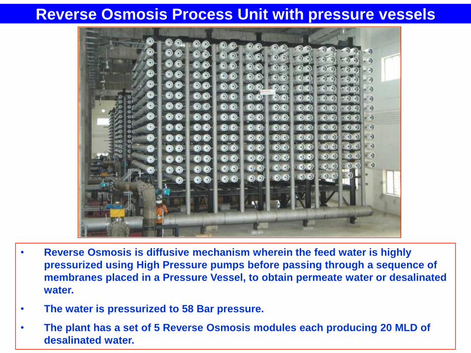
Reverse Osmosis Process Unit with pressure vessels
• Reverse Osmosis is diffusive mechanism wherein the feed water is highly
pressurized using High Pressure pumps before passing through a sequence of
membranes placed in a Pressure Vessel, to obtain permeate water or desalinated
water.
• The water is pressurized to 58 Bar pressure.
• The plant has a set of 5 Reverse Osmosis modules each producing 20 MLD of
desalinated water.
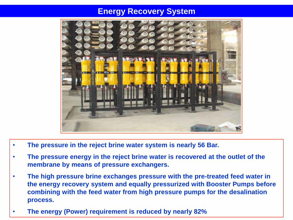
Energy Recovery System
• The pressure in the reject brine water system is nearly 56 Bar.
• The pressure energy in the reject brine water is recovered at the outlet of the
membrane by means of pressure exchangers.
• The high pressure brine exchanges pressure with the pre-treated feed water in
the energy recovery system and equally pressurized with Booster Pumps before
combining with the feed water from high pressure pumps for the desalination
process.
• The energy (Power) requirement is reduced by nearly 82%
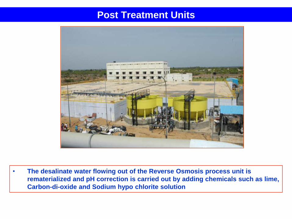
Post Treatment Units
• The desalinate water flowing out of the Reverse Osmosis process unit is
rematerialized and pH correction is carried out by adding chemicals such as lime,
Carbon-di-oxide and Sodium hypo chlorite solution
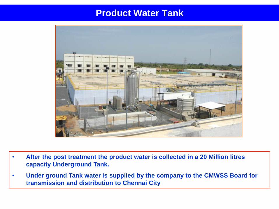
Product Water Tank
• After the post treatment the product water is collected in a 20 Million litres
capacity Underground Tank.
• Under ground Tank water is supplied by the company to the CMWSS Board for
transmission and distribution to Chennai City
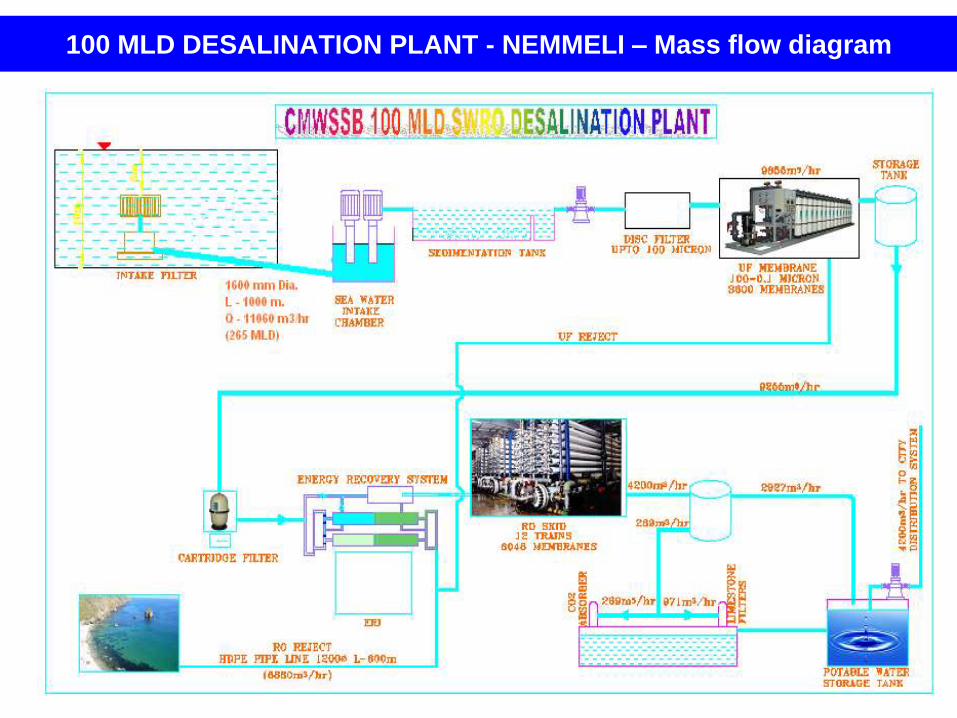
100 MLD DESALINATION PLANT - NEMMELI – Mass flow diagram
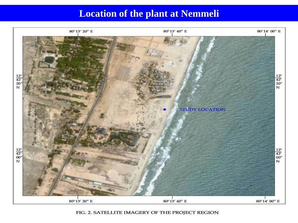
Location of the plant at Nemmeli
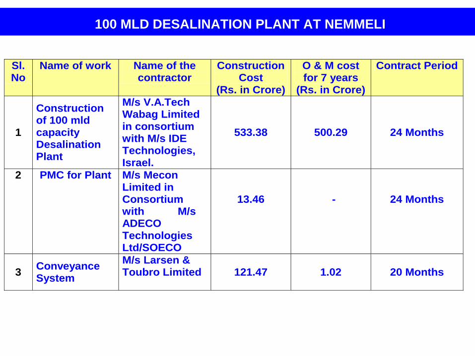
100 MLD DESALINATION PLANT AT NEMMELI
Sl.No
Name of work Name of the contractor
Construction Cost
(Rs. in Crore)
O & M cost for 7 years
(Rs. in Crore)
Contract Period
1
Construction of 100 mld capacity Desalination Plant
M/s V.A.Tech Wabag Limited in consortium with M/s IDE Technologies, Israel.
533.38 500.29 24 Months
2 PMC for Plant M/s Mecon Limited in Consortium with M/s ADECO Technologies Ltd/SOECO
13.46
-
24 Months
3 Conveyance System
M/s Larsen & Toubro Limited
121.47 1.02 20 Months
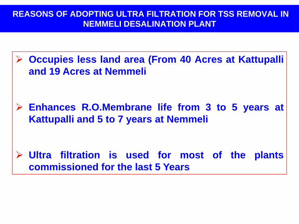
REASONS OF ADOPTING ULTRA FILTRATION FOR TSS REMOVAL IN
NEMMELI DESALINATION PLANT
Occupies less land area (From 40 Acres at Kattupalli
and 19 Acres at Nemmeli
Enhances R.O.Membrane life from 3 to 5 years at
Kattupalli and 5 to 7 years at Nemmeli
Ultra filtration is used for most of the plants
commissioned for the last 5 Years
SEWAGE RENOVATION FOR INDUSTRIAL USE
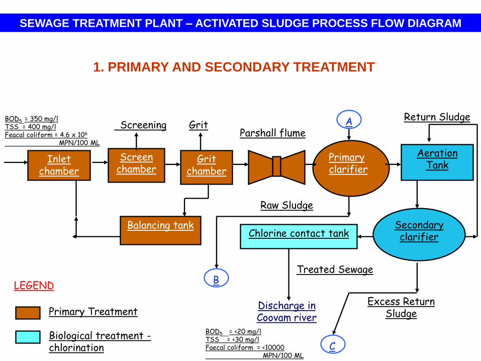
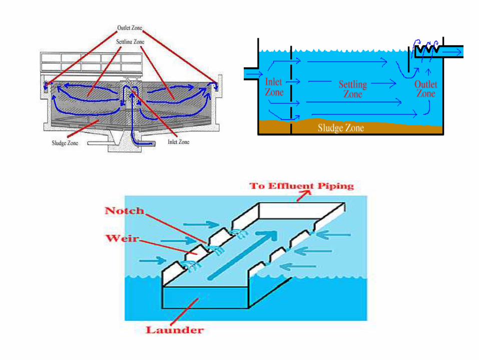
Screen chamber
Primary clarifier
Aeration Tank
Balancing tank
Parshall flumeA
Secondary clarifierChlorine contact tank
Treated Sewage
Screening Grit
Excess Return Sludge
Raw Sludge
BOD5 = <20 mg/lTSS = <30 mg/lFaecal coliform = <10000
MPN/100 ML
Primary Treatment
Biological treatment -chlorination
LEGEND
Inlet chamber
Grit chamber
BOD5 = 350 mg/lTSS = 400 mg/lFeacal coliform = 4.6 x 10⁶
MPN/100 ML
Return Sludge
B
C
Discharge in Coovam river
1. PRIMARY AND SECONDARY TREATMENT
SEWAGE TREATMENT PLANT – ACTIVATED SLUDGE PROCESS FLOW DIAGRAM
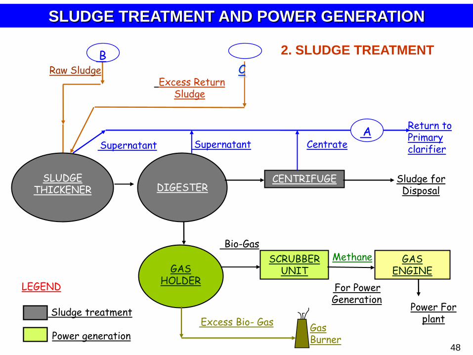
48
DIGESTERCENTRIFUGE
GAS HOLDER
SCRUBBER UNIT
SLUDGE THICKENER
A
For Power Generation
Bio-Gas
Power For plantExcess Bio- Gas
Sludge for Disposal
Excess Return Sludge
Raw Sludge
Supernatant
Return to Primary clarifierSupernatant Centrate
GAS ENGINE
Methane
Gas Burner
SLUDGE TREATMENT AND POWER GENERATION
BC
Sludge treatment
Power generation
LEGEND
2. SLUDGE TREATMENT
TERTIARY TREATMENT PLANTS INSTALLED
BY CPCL AT MANALI
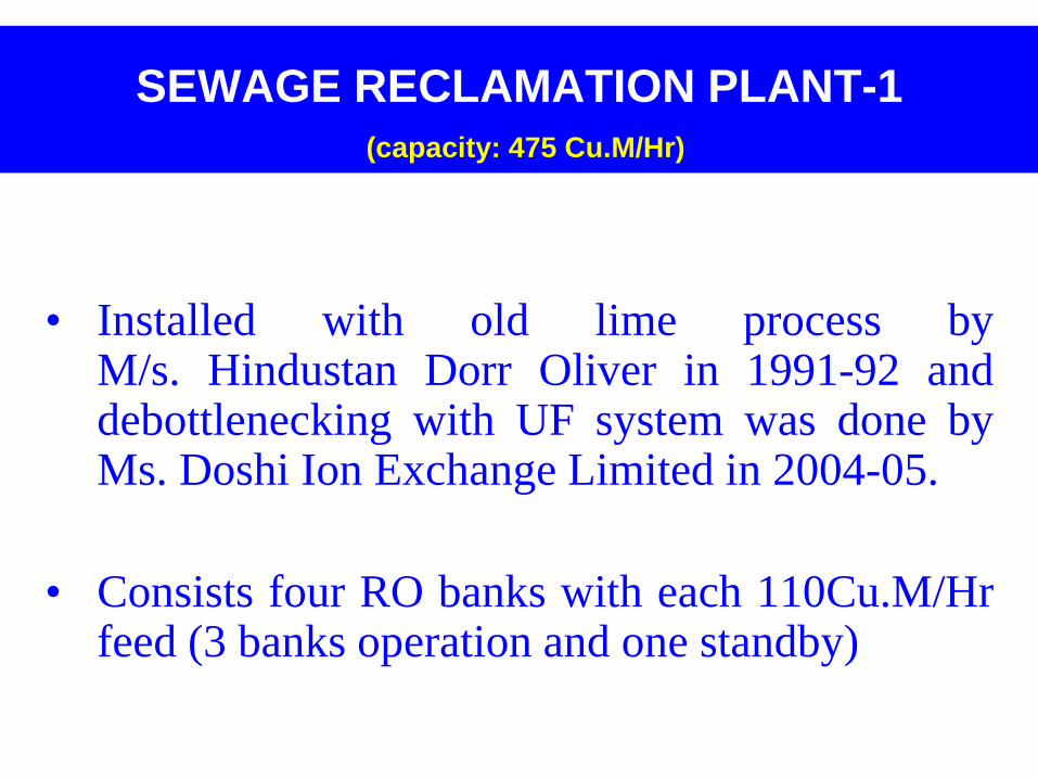
SEWAGE RECLAMATION PLANT-1
(capacity: 475 Cu.M/Hr)
• Installed with old lime process byM/s. Hindustan Dorr Oliver in 1991-92 anddebottlenecking with UF system was done byMs. Doshi Ion Exchange Limited in 2004-05.
• Consists four RO banks with each 110Cu.M/Hrfeed (3 banks operation and one standby)
ClarifiersSurface
Aeration
Tanks
Hydro-
treater
Intermediate
storage
pond
Multimedia
filter
Ultra-
Filtration
Pressure
sand filter
Reverse
OsmosisUF Product
tank
Degasser
FeCl3 & Anionic
Poly dosing
Refinery /
Canteen Sewage
Secondary
treated sewage
Cooling Tower make-up or
Additional RO feed ZDPII
Chemical dosing
SBS,HCl,Antiscalant
Rejects to RORR
Old permeate
tank (PT-1)
DM Plant
Sewage Reclamation Plant - I (SRP-I)
3.0MGR
Chlorine
1.5 MGR for CT makeup
Permeate
Reject
Cartridge
filter
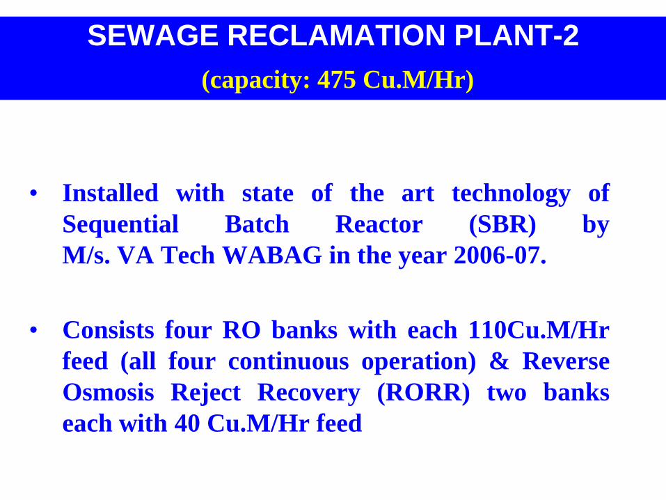
SEWAGE RECLAMATION PLANT-2
(capacity: 475 Cu.M/Hr)
• Installed with state of the art technology of
Sequential Batch Reactor (SBR) by
M/s. VA Tech WABAG in the year 2006-07.
• Consists four RO banks with each 110Cu.M/Hr
feed (all four continuous operation) & Reverse
Osmosis Reject Recovery (RORR) two banks
each with 40 Cu.M/Hr feed
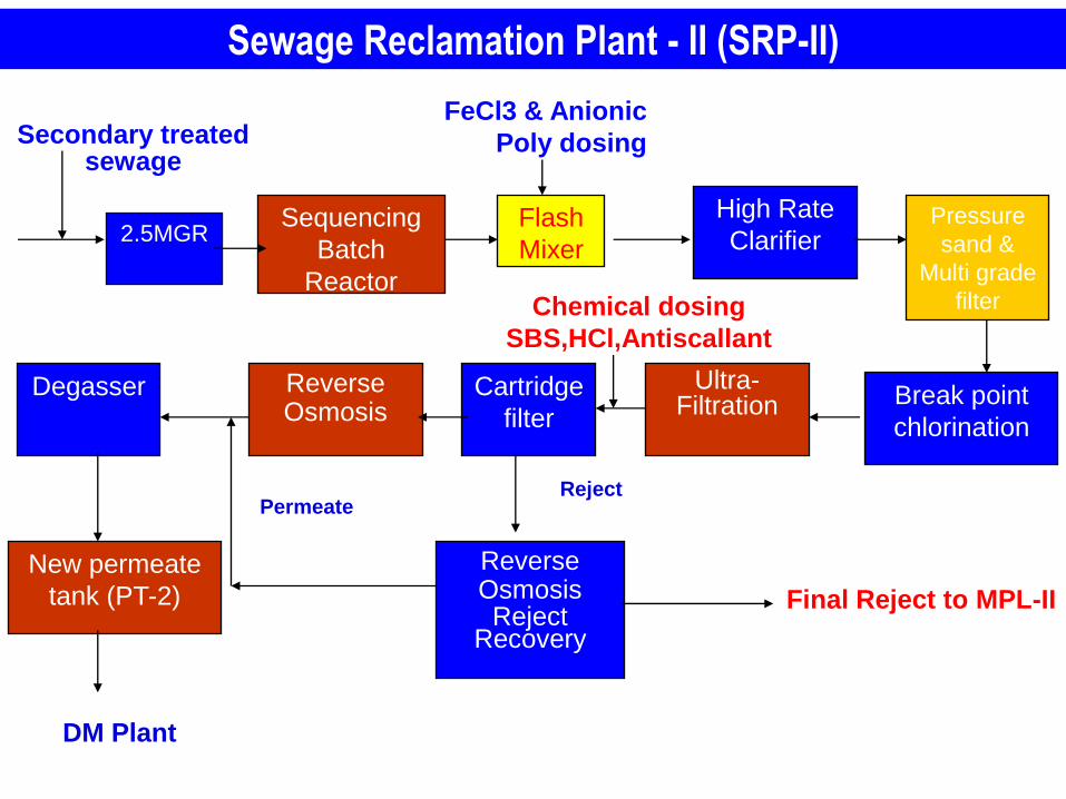
High Rate
ClarifierSequencing
Batch
Reactor
Pressure
sand &
Multi grade
filter
Flash
Mixer
Ultra-Filtration Break point
chlorination
Reverse Osmosis
FeCl3 & Anionic
Poly dosingSecondary treated sewage
Chemical dosing
SBS,HCl,Antiscallant
DM Plant
Degasser
Reverse Osmosis Reject
Recovery
New permeate
tank (PT-2)
Sewage Reclamation Plant - II (SRP-II)
Final Reject to MPL-II
2.5MGR
PermeateReject
Cartridge
filter
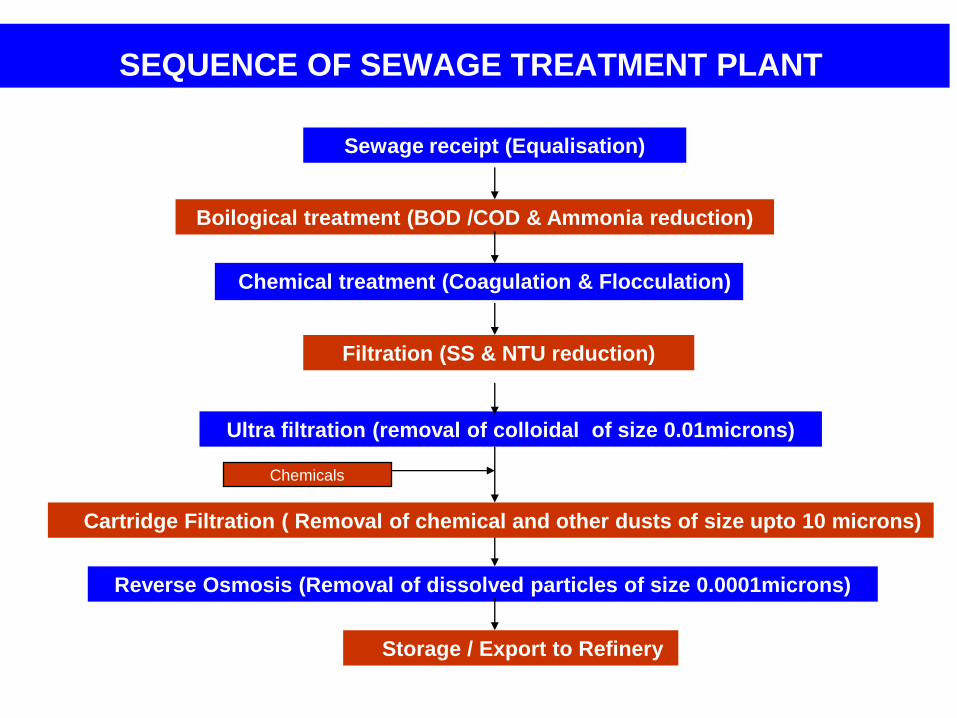
SEQUENCE OF SEWAGE TREATMENT PLANT
Sewage receipt (Equalisation)
Boilogical treatment (BOD /COD & Ammonia reduction)
Chemical treatment (Coagulation & Flocculation)
Filtration (SS & NTU reduction)
Ultra filtration (removal of colloidal of size 0.01microns)
Reverse Osmosis (Removal of dissolved particles of size 0.0001microns)
Storage / Export to Refinery
Cartridge Filtration ( Removal of chemical and other dusts of size upto 10 microns)
Chemicals
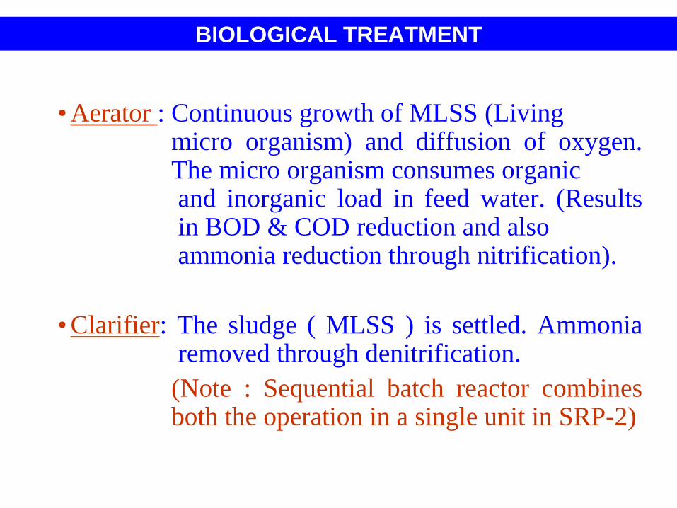
BIOLOGICAL TREATMENT
•Aerator : Continuous growth of MLSS (Livingmicro organism) and diffusion of oxygen.The micro organism consumes organicand inorganic load in feed water. (Resultsin BOD & COD reduction and alsoammonia reduction through nitrification).
•Clarifier: The sludge ( MLSS ) is settled. Ammoniaremoved through denitrification.
(Note : Sequential batch reactor combinesboth the operation in a single unit in SRP-2)
CHEMICAL TREATMENT
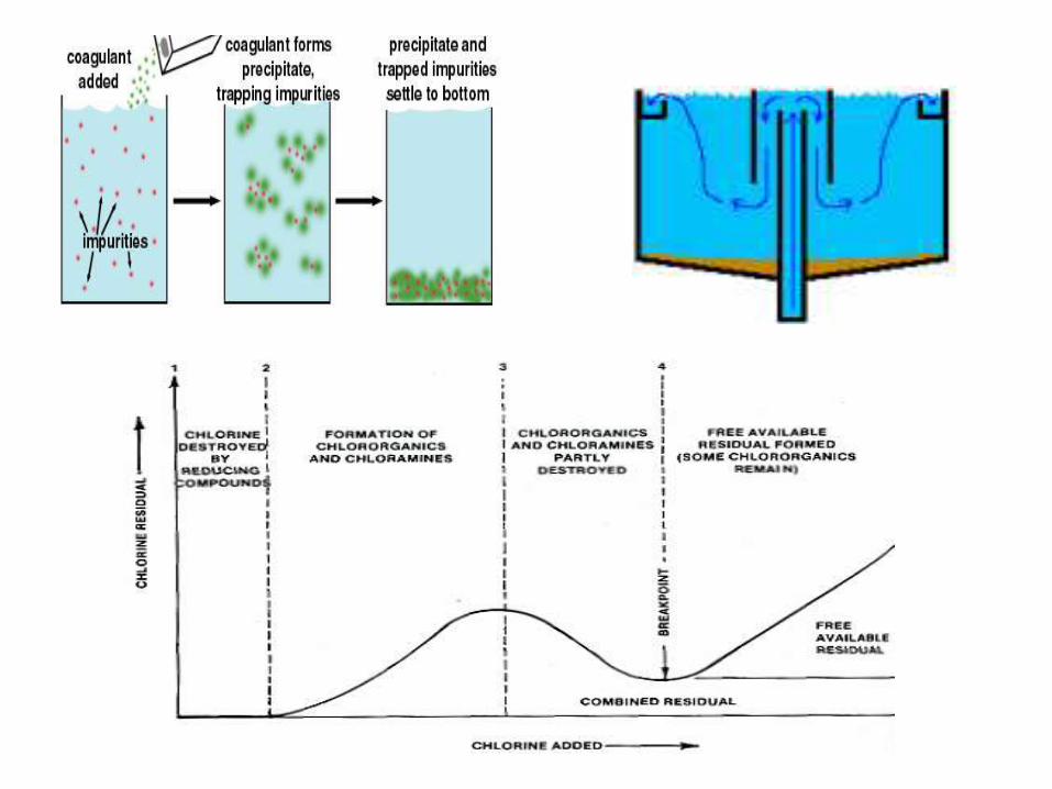
• Hydro Treater High rate clarifier : coagulation
of suspended particles and phosphates by addtion
of ferric chloride and flocculation by addition of
anionic poly electrolyte
• Chlorination Break point chloriantion:
Disinfection of bacteria and removal of residual
ammonia by conversion to chloroamines
FILTRATION
• Pressure Sand / Multimedia Multi grade filters :
Removal of particle size upto 0.45 microns and iron thereby
reducing Suspended Solids (SS) & Trubidity (NTU).
• Pressure sand filters loaded with grades of pebbles , coarse
and fine sand
• Multimedia filters have additional layer of Anthracite for
polishing
CARTRIDGE FILTRATION
• Removal of chemical dust due to addition of Hydrochloric
acid, Sodium Bi sulphite and Antiscalants and dust from
feed tanks (up to particle size 10 microns)
• The cartridge filter is of spiral wound and thread type and
the thread made of Poly propylene or polyethylene material.
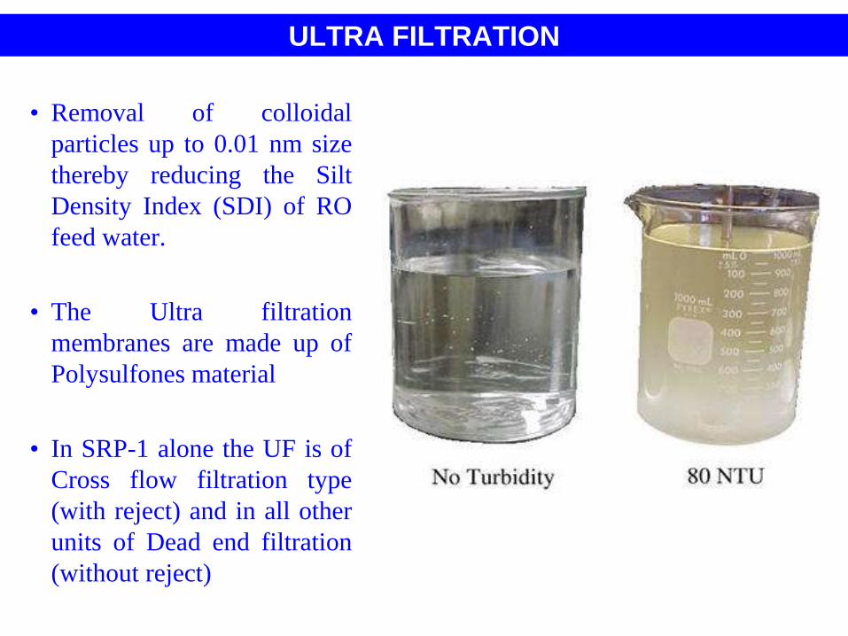
ULTRA FILTRATION
• Removal of colloidal
particles up to 0.01 nm size
thereby reducing the Silt
Density Index (SDI) of RO
feed water.
• The Ultra filtration
membranes are made up of
Polysulfones material
• In SRP-1 alone the UF is of
Cross flow filtration type
(with reject) and in all other
units of Dead end filtration
(without reject)
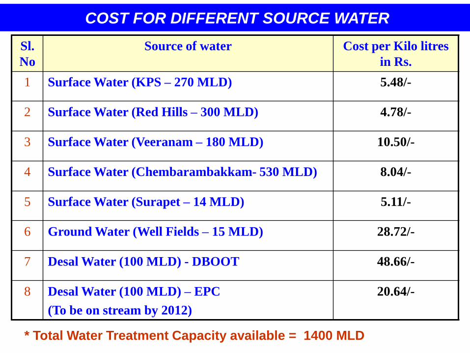
COST FOR DIFFERENT SOURCE WATER
Sl.
No
Source of water Cost per Kilo litres
in Rs.
1 Surface Water (KPS – 270 MLD) 5.48/-
2 Surface Water (Red Hills – 300 MLD) 4.78/-
3 Surface Water (Veeranam – 180 MLD) 10.50/-
4 Surface Water (Chembarambakkam- 530 MLD) 8.04/-
5 Surface Water (Surapet – 14 MLD) 5.11/-
6 Ground Water (Well Fields – 15 MLD) 28.72/-
7 Desal Water (100 MLD) - DBOOT 48.66/-
8 Desal Water (100 MLD) – EPC
(To be on stream by 2012)
20.64/-
* Total Water Treatment Capacity available = 1400 MLD