Advanced turboprop testbed systems study
276
NASA Contractor Report 167895 NASA-CR-167895 19820025499 ;(I/-JSA -c'I<- /67 g7s / '- , " Advanced Turboprop Testbed Systems Study 1. M. Goldsmith McDonnell Douglas Corporation Douglas Aircraft Company Long Beach, California 90846 I CONTRACT NAS3 0 22347-'I' IJULY, 1982 i NI\S/\ National Aeronautics and Space Administration Lewis Research Center Cleveland. Ohio 44135 - 1/11111111111 1111 11111 11111111111111111111111 : NF02695 tlBRAR'{ C: P'I OCT 15 1982 LANGLEY RESEARCH CCNTER LIBRARY, NASA VIRGINIA https://ntrs.nasa.gov/search.jsp?R=19820025499 2018-02-15T08:59:59+00:00Z
Transcript of Advanced turboprop testbed systems study
NASA Contractor Report 167895
NASA-CR-167895 19820025499
;(I/-JSA -c'I<- /67 g7s /
'- , "
Advanced Turboprop Testbed Systems Study
1. M. Goldsmith
McDonnell Douglas Corporation Douglas Aircraft Company Long Beach, California 90846
I CONTRACT NAS3 0 22347-'I' IJULY, 1982 i
NI\S/\ National Aeronautics and Space Administration
Lewis Research Center Cleveland. Ohio 44135
-
1/11111111111 1111 11111 11111111111111111111111 : NF02695
tlBRAR'{ C: P'I OCT 15 1982
LANGLEY RESEARCH CCNTER LIBRARY, NASA
HAM~TOl'JL VIRGINIA
https://ntrs.nasa.gov/search.jsp?R=19820025499 2018-02-15T08:59:59+00:00Z

DOUGLAS AIRCRAFT COMPANY
3855 Lakewood Boulevard Long Beach, California 90846
Cl-091-ACEE-495 17 September 1982
To: Report Distribution
. '.
The attached report, NASA CR-167895, "Advanced Turboprop Testbed Systems Study", July 1982, is transmi tted to you at the request of NASA lewis Research Center, Cleveland, Ohio. This is the Douglas Aircraft Company study report prepared under Contr.act NAS3-22347.
Any questions relating to the report may be directed to Irene M. Goldsmith, Douglas Aircraft Company, long Beach, California, Telephone (213) 593-0354, or G. K. Sievers, NASA lewis Research Center, Telephone (216) 433-4000.
Program Manager, ACEE
. .
. . . /
MCDON,!,ELL'DOUG~ COR~RAnoN
NASA Contractor Report 167895
Advanced Turboprop Testbed Systems Study
I. M. Goldsmith McDonnell Douglas Corporation Long Beach, California
Prepared for Lewis Research Center under Contract NAS3-22347
NI\S/\ National Aeronautics and Space Administration
Lewis Research Center Cleveland. Ohio 44135


FOREWORD
This document presents the results of a Contract Study (NAS3-22347), (Reference 1),
for the National Aeronautics and Space Administration (NASA) by Douglas
Aircraft Company, McDonnell Douglas Corporation. This work is part of the
prop-fan program in the overall Aircraft Energy Efficiency (ACEE) program of
which Max Klotzsche is the Douglas Program Manager. The Douglas Project
Manager of the Advanced Turboprop Projects is Irene M. Goldsmith.The NASA
technical monitor for the.contract is Brent A. Miller, Project Engineer of the
Advanced Turboprop Project Office of NASA Lewis Research Center. The overall
direction and coordination of the Advanced Turboprop Program (ACEE) is provided
by NASA Lewis Research Center.
The following Douglas personnel from the key engineering discipline groups have
made major contributions to this study:
H. R. Welge
R. W. Hahn
R. E. Adkisson
R. E. Pearson
F. S. La Mar
R. G. Sandoval
D. E. Delaney
B. W. Kimoto
M. M. Platte
R. A. Wright
W. E. Bachand
S. G. Furniss
Unit Chief - Advanced Aircraft Design - Aerodynamics
Section Chief - Advanced Aircraft Design - Performance
Section Chief - Design - Structural Advanced Design
Dynamics Structural Mechanics
Project Engineer - Power Plant
Project Engineer - Power Plant
Acoustic Design Requirements
Advanced Weight Engineering
Branch Chief - Technology - Systems Analysis
Unit Chief - Technology - Configuration Design
Director/Flight Test
Flight Test
Subcontractors to Douglas Aircraft on the study are as follows:
Prop-fan and Prop-fan Controls - Hamilton Standard, Windsor Locks, Conn.,
Principal contacts: W. M. Adamson & B. Z. Gatzen
Turboshaft Engine, Gearbox and Controls - Detroit Diesel Allison,
Indianapolis, Indiana
Principal contact: P. Stolp
iii

This Page Intentionally Left Blank
TASK
I
II
ADVANCED TURBOPROP TESTBED SYSTEMS STUDY
TABLE OF CONTENTS
SUMMARY
INTRODUCTION
RECOMMENDED TESTBED PROGRAM OBJECTIVES AND PRIORITIES
General
Large Scale Prop-fan Rotor Test Objectives
Structural Dynamics
Acoustics .
Performance
Summary of Prop-fan Testbed Program Priorities
Testbed Acoustic Objectives
Resolution of Acoustic Objectives •.••
Integrated Prop-fan/Aircraft Aerodynamics Aspects
Aircraft Characteristics
Propulsive Efficiency
Inlet Engine Compatibility fI' • •
1
5
11
11
13
13
18
21
24
24
27
35
36
37
37 Integration of Hechanical Controls with Engine and Prop-fan 38
Integration and Compatibility of Prop-fan/Inlet/Engine 38
CANDIDATE PROPELLER DRIVE SYSTEHS
Engine/Gearbox • • • • •
T701 Engine/Modified T56 Gearbox
T64 Engine/Gearbox
T56 Engine/Gearbox
Large Scale Prop-fan/Prop-fan Controls
54H60 Propeller Control and Modifications Required
New Propeller Control
Free Turbine vs. Single Shaft Engine Controls
Prop-fan Control Capability . . • . . . . ..
Prop-fan/Nacelle Compatibility • • • • •
Cockpit Controls and Instrumentation
Drive System Summary
v
39
39
44
47
48
50
50
52
53
55
55
57
58

CONTENTS (Continued)
TASK Page
III
IV
V
CANDIDATE TESTBED AIRCRAFT
Initial Survey of Possible Candidates
Advantages of DC-9 as Selected Prop-fan Testbed
DC-9 Testbed Configurations
Stability and Control Characteristics
DC-9 Prop-fan Performance Estimates
TESTBED SYSTEM EVALUATION AND RECOMMENDATIONS
Testbed Program Recommendations
Engine Selection
T70l Merits versus T56
Aerodynamic Testbed Program
High Speed Wind Tunnel Test
Low Speed Wind Tunnel Test
Inlet Development ••••
Subscale Wind Tunnel Program • • . .
Estimated Cost and Schedule • • • •
Flight Test • • • • • • • • • •
Propulsion System - Prop-fan/T70l Engine Integration
Fuel System
Opposite Rotation
Key Characteristics of Prop-fan Propulsion System
Acoustic Testbed Program • • . • . • • • • . • •
Resolution of Acoustic Technology Objectives
CONCEPTUAL DESIGN OF TESTBED SYSTEMS
Nacelle and Wing Structural Integration
Structural Configuration
Nacelle Attachment to Existing Wing Structure
Preliminary Load Criteria
Preliminary Whirl Mode Analysis
Prop-fan Excitation Factors
Alternate Testbed Structural Arrangement
Preferred Nacelle/Wing Installation
vi
61
61
63
65
68
70
77
77
78
78
78
79
82
83
85
85
86
92
94
94
95
96
97
107
109
113
114
115
118
119
122
123
CONTENTS (Continued)
TASK Page
VI
VII
Prop-fan Configuration Weights 124
One T701 Prop-fan Configuration
Two T701 Prop-fan Configuration
One T56 Prop-fan Configuration
Weight Comparison Study
TESTBED TEST PROGRAM PLAN
Data Monitoring, Processing Facilities and Systems
Facilities
Performance Data Systems
Acoustics and Vibration Facility and Systems
Two Nacelle Prop-fan Configuration • • • •
Testing • • . .
Initial Ground Tests
Airplane MOdification
Complete Aircraft Ground Tests
Flight Tests
124
132
136
140
141
142
142
142
144
144
146
146
152
152
153
Cruise Performance/Wing and Nacelle Pressure Survey 160
Preliminary Test Schedule
One Nacelle Prop-fan Configuration
LARGE SCALE WIND TUNNEL PROGRAM PLAN
Compatibility of Large Scale Flight Hardware and Wind Tunnel Test Model ••• • • • . • • • • • • • • • • • •
Large Scale Wind Tunnel Characteristics . . . . Wind Tunnel Model Strength Requirements
Low Speed Wind Tunnel Testbed Installation
High Speed Wind Tunnel Testbed Installation
Large Scale Wind Tunnel Recommendations ••••
ROM COSTS OF TWO-NACELLE PROP-FAN TESTBED PR0GRAM
Background
Major Element Description • • • • • •
Preliminary Design Through PDR
REFERENCES .
APPENDIX I
APPENDIX II
APPENDIX III vii
161
162
163
163
164
166
166
167
169
171 171 171 171
179
181
187
219

This Page Intentionally left Blank

Figure No.
Frontispiece
1
2
3
4
5
6
7
8
9
10
11
12
13
14
15
16
17
18
l7A
FIGURES
Proposed DC-9-l0 Prop-fan Research Aircraft
DC-9-l0 Prop-fan Research Aircraft One Prop-fan Nacelle Configuration
DC-9-l0 Prop-fan Research Aircraft Two Prop-fan Nacelle Configuration
Role of Flight Testbed on Propulsion Technology Issues
Prop-fan Installation Arrangements
Comparison of Advanced and Current Inlet/Propeller Relationship
Performance Comparison Between P3A Vertical Rake and SR-3 Prop-fan with 35% Body • • • .
Blockage Comparison Between P3A Vertical Rake and SR-3 Prop-fan with 35% Body • . . •
Candidate Propeller Drive Systems
Estimated Capability with Fixed Ratio Gearbox
Propeller Drive System Comparison Summary
DC-9-l0 Prop-fan Testbed - (1) Allison T70l Engine
DC-9-10 Prop-fan Testbed - (1) Allison T56 Engine
DC-9-l0 Prop-fan Testbed - (2) Allison T70l Engines
DC-9-30 Prop-fan Testbed - (2) Allison T70l Engines
Prop-fan Testbed Flight Envelope for Stability and Control • . . . •
Limiting Operating Points Assumed in Performance Spectrum •••..
DC-9-l0 Testbed Available Cruise Time (2 Allison T70l Engines)
DC-9-l0 Testbed Available Cruise Time (1 Allison T70l Engines)
DC-9-30 Testbed Available Cruise Time (2 Allison T70l Engine)
ix
i
7
7
39
39
43
56
56
58
58
59
66
66
67
67
68
70
72
72
74

FIGURES (Continued)
Figure No. Page
18A
19
20
21
22
23
24
25
26
27
28
29
30
31
32
33
34
35
36
37
38
DC-9-30 Testbed Available Cruise Time (1 Allison T701 Engine) .•••
Percent Power Required from Turbofan DC-9-10 Prop-fan Cruise - T701
Percent Power Required from Turbofan DC-9-10 Prop-fan Cruise - T56
Percent Power Required from Turbofan DC-9-30 Cruise - T701 . . . . . .
Engines During
· · · · . . . Engines During
· · · · . . . Engines During
· · · · DC-9-10 Prop-fan Testbed Flight Limits in Cruise -Two Allison T701 Prop-fans Only
Aerodynamic Test Plan Summary
High-Speed Wind Tunnel Model
Low-Speed Wind Tunne1/DC-9 Model
Inlet Testing
Aero Development Plan - Wind Tunnel Test and Schedule . • . • . . . . • •
Limiting Operating Points Assumed in Performance Spectrum
Cruise Performance Pressure Survey Instrumentation
T701 Engine/Prop-fan Installation
T701 Engine/Prop-fan Installation - Section Cuts
DC-9 Prop-fan Flight Testbed Fuel System
Production DC-9 Sidewall Acoustic Treatment
Resolution of Acoustic Technology Objectives
Acoustic Test Requirements
Isogrid Structure
Modified Sidewall Acoustic Treatment
Measurement of Near- and Far-Field Noise on Outdoor Test Stand . . • . • • . • • . . •
x
. .
. .
74
76
76
76
75
79
79
82
83
85
87
91
92
92
94
97
97
99
100
100
101

FIGURES (Continued)
Figure No. Pase
39
40
41
42
43
44
45
46
47
48
49
50
51
52
53
54
55
56
57
58
59
Measurement of Far-Field Noise During Ground Runup . . . . . . ~ . . . . . .
Measurement of Exterior/Interior Noise and Fuselage Vibration • • . • . . • . •
DC-9 Lift Variation with Angle of Attack
DC-9 Wing Body Flow Fields
Installation of Allison T70l Engine and Prop-fan Assembly on DC-9-l0 Aircraft Wing
Installation of Allison T56 Engine and Prop-fan Assembly on DC-9-l0 Aircraft Wing . • • .•
Minimum Prop-fan Nacelle Length and Load Data
Recommended Nacelle/Prop-fan Diameter Ratio
Recommended Prop-fan Spinner and Hub Design
DC-9 Prop-fan Nacelle Structure
Schematic of Nacelle/Wing Structural Intersection
Aircraft Design Speeds
Nacelle Structural Loads
Nacelle/Wing Frame Support Loads
Nacelle Stiffness Required to Prevent Whirl Flutter Versus Prop-fan Diameter-to-Nacelle-Length Ratio
Stiffness of Prop-fan Nacelle
Whirl Flutter Boundary
Effect of Direction of Prop-fan Rotation and Excitation Factors (EF) of Prop-fan Installation
DC-9-l0 and DC-9-30 Prop-fan Excitation Factors
Sensitivity of Prop-fan Excitation Factor to Nacelle Installation Geometry . . • •
Proposed Nacelle Testbed Arrangement for Various Prop Locations and Tilt Relative to the Wing
xi
102
105
107
108
110
110
111
112
113
113
115
116
117
117
118
118
119
120
120
121
122

FIGURES (Continued)
Figure No. Page
60
61
62
63
64
65
66
67
68
69
70
71
72
73
74
75
76
77
78
Engine/Prop-fan Structural Mounting Concept Advantages
DC-9-10 C.G. Diagram
DC-9-10 Prop-fan Testbed Group Weight Summary
DC-9-10 Testbed Aircraft Operating Envelope
Hamilton Standard Propeller Test Facility -Windsor Locks, Conn. _... • ....
Detroit Diesel Allison Engine Test Facility -Indianapolis, Ind.
Douglas Outdoor Engine Test Facility -Quartzsite, Arizona . . . • • . . . • • . . •
Effect of Prop-fan Location Relative to Wing
Structural and Aerodynamic Damping
Proposed Loads Test Points
Cruise Performance/Wing and Nacelle Pressure Survey .
Preliminary Flight Test Schedule
Compatibility of Prop-fan/Engine/Nacelle Flight Test Installation with Wind Tunnel Test Model . . . .
Survey of Probable Wind Tunnel Facilities for Prop-fan Testbed Testing • . • . . . . .
Wind Tunnel Capabilities and Limitations Summary
Estimated Total Costs for Prop-fan Testbed Program
Douglas Aircraft Prop-fan Testbed Program Schedule
Hamilton Standard Prop-fan Testbed Program Schedule •
Detroit-Diesel Allison Prop-fan Testbed Program Schedule . . . . . . . . . . . . . . . . . . .
xii
123
131
140
145
148
149
150
154
156
157
160
162
163
165
165
176
177
177
178
Table No.
1
2
3
SA
SB
6
7A
7B
8
9A
9B
10
TABLES
Aero Objectives to Verify Feasibility Acceptance of Prop-fan . • • • . • • • •
Comparison of SHP/D2 Capabilities
Prop-fan Pitch Change Rates
Weights and Geometry - Baseline DC-9-10 Aircraft
DC-9-10 Prop-fan Testbed Group Weight Summary -One Wing Mounted Allison T70l Prop-fan - English Units
DC-9-l0 Prop-fan Testbed Group Weight Summary -One Wing Mounted Allison T701 Prop-fan - Metric Units
Testbed Operational Items Weight - One Allison T701 Prop-fan . • • • . • • • . • • • • • • •
DC-9-10 Prop-fan Testbed Group Weight Summary - Two Wing Mounted Allison T701 Prop-fan - English Units • •
DC-9-10 Prop-fan Testbed Group Weight Summary - Two Wing Mounted Allison T701 Prop-fan - Metric Units
Testbed Operational Items Weight - Two Allison -T701 Prop-fan • • • • • • • • • • • . • .
DC-9-10 Prop-fan Testbed Group Weight Summary - One Wing Mounted Allison T56 Prop-fan - English Units
DC-9-10 Prop-fan Testbed Group Weight Summary - One Wing Mounted Allison T56 Prop-fan - Metric Units
Testbed Operational Items Weight - One Allison T56 Prop-fan • • • • • • • • • • •
xiii
35
41
51
125
126
127
130
133
134
135
137
138
139


ADVANCED TURBOPROP TESTBED SYSTEMS STUDY
SUMMARY
The work performed by Douglas Aircraft Company, under Contract No. NAS3-22347,
(Reference 1) with NASA Lewis Research Center is summarized herein and concerns
the evaluation and recommendations of a testbed approach to the proof of
conce~, feasibility, and verification of the advanced prop-fan and of the
integrated advanced prop-fan aircraft. All previous study work throughout the
industry on the prop-fan concept has shown a definite fuel saving for the
prop-fan aircraft as compared to the turbofan aircraft. These analytical
comparisons show a 16 percent to 38 percent fuel savings of the prop-fan over
the current turbofan engine ·powered aircraft; as compared to an advanced
technology turbofan engine compatible with a 1990 to 1995 operation, the
prop-fan shows a definite advantage of at least 15 percent fuel savings. The
decreasing availability and the rapid escal tion of price of fossil fuel have
made industry increasingly desirous of having this fuel economy available from
the prop-fan in actual operation.
In Phase I (FY 1978 through 1980) of the NASA Advanced Turboprop (ATP) Program,
a fundamental data base on small scale prop-fan models was developed and the
feasibility of the high speed (Mach 0.70 to 0.80) prop-fan was established.
The next follow-on step in the prop-fan development is to provide proof-of
concept by large scale testbed research and demonstration. The proof of the
prop-fan itself is the key to the success of the prop-fan aircraft; therefore,
proof of full scale prop-fan structural integrity, acceptable noise levels, and
performance are the first priority items in the testbed program. This study
reported herein provides the necessary survey, planning, and early preliminary
aircraft design information associated with the initiation and continuation of
a suitable large scale prop-fan testbed program. Compliance with an expedited
schedule necessitates that the testbed aircraft/engine/prop-fan/controls
consider existing hardware.
1

The facets of the overall testbed problem included in this study are the
objectives and priorities of the testbed program; survey and selection of
candida te propeller drive sys tems; selection of a satisfactory aircraft, from
candidate aircraft, for the testbed; proposed testbed systems evaluation and
recommendtions; conceptual design of a testbed; ROM costs; preliminary testbed
flight program; and survey of wind tunnel facilities suitable for large scale
prop-fan and prop-fan aircraft testing.
The Douglas study considers the DC-9-10 (or -30) as the testbed air~raft.
Throughout, the Hamilton Standard SR-3 design type prop-fan is selected; the
actual design of the testbed large scale prop-fan will be designated as SR-7,
but is expected to have the design and performance characteristics similar to
the existing SR-3. In the iniitial phase of the study, the Allison T701, the
Allison T56, and the General Electric T64 turboshaft engines are compared as to
the feasibility of each type as a drive system for the prop-fan testbed. One
and two prop-fan nacelles are considered for the tes tbed arrangement. Since
the unmodified DC-9 aircraft empennage is capable of satisfactory flight with
the asymmetric configuration, one wing-mounted prop-fan nacelle configuration
is considered as a less costly version of the testbed. However, since the two
nacelle prop-fan arrangement is more desirable from the Contractor's point of
view, it is considered as the primary arrangement.
For this proposed testbed aircraft concept, the major modification to the
aircraft is design and mounting of the wing-mounted prop-fan nacelles. The
arrangement considered in this study is a simple, primary structure, monocoque
nacelle mounted at four points to the wing front and aft spar. Such an
arrangement permits a well forward location of the prop-fan relative to the
wing leading edge, provides ease of mainntenance (as the propulsion system
components may be removed from the nacelle in a modular fashion without
interference with the wing basic structure or fuel tankage) and results in an
integrated prop-fan arrangement having a desired excitation factor.
2

General conclusions from the study are:
o A prop-fan testbed aircraft program is definitely feasible and
necessary for verification of prop-fan/engine/nacelle/aircraft
integration.
o The DC-9 aircraft is a particularly desirable testbed aircraft since
o it requires no configuration modification except the addition
of the wing-mounted prop-fan nacelle(s);
o all facets of the DC-9 are known to Douglas and, thus, the
installation of the prop-fan can be efficiently accomplished;
o the aircraft is a commercial aircraft and a desirable size
from the airline's point of view.
o Of the currently available turboshaft engines, the Allison T701 is
most suitable as a propulsor for the prop-fan aircraft testbed.
o Modification of existing engine and propeller controls is adequate for
the prop-fan testbed.
o The airframer is considered the logical systems integrator of the
testbed program; full cooperation of the prop-fan manufacturer, the
engine and gearbox manufacturer, and the airframer is required to
accomplish a successfully expedited testbed ready for flight in 1986.
o Flight test is essential for establishing the necessary proof-of
concept, valid evaluation, and confidence in prop-fan itself and the
proper integration into a prop-fan aircraft.
o Large scale wind tunnel testing will not provide adequate results for
validation of the prop-fan as integrated into an aircraft.
3

o Sub-scale wind tunnel testing is feasible for exploration and
parametric evaluation required in establishing the basic
configurration assessments necessary in selecting a suitable or "near
optimum" integrated testbed aircraft arrangement.
o Opposite rotation (both prop-fans rotating inboard and upward toward
the fuselage) is shown to be advantageous from the performance and
acoustic points of view; continued analysis and design work is
warranted.
o Synchrophasing of the prop-fans is necessary for establishing
satisfactory acoustic performance in the case of the two prop-fan
nacelle configuration.
o The DC-9-10 testbed aircraft provides suitable configuration for
measurement during flight of prop-fan near field and far field
acoustic characteristics since the basic JT8D turbofan engines in the
DE-9-10, operated in conjunction with the prop-fan propulsion system,
do not generate background noise which will interfere with valid
measurement of the prop-fan acoustic characteristics.
4

ADVANCED TURBOPROP TESTBED SYSTEMS STUDY
INTRODUCTION
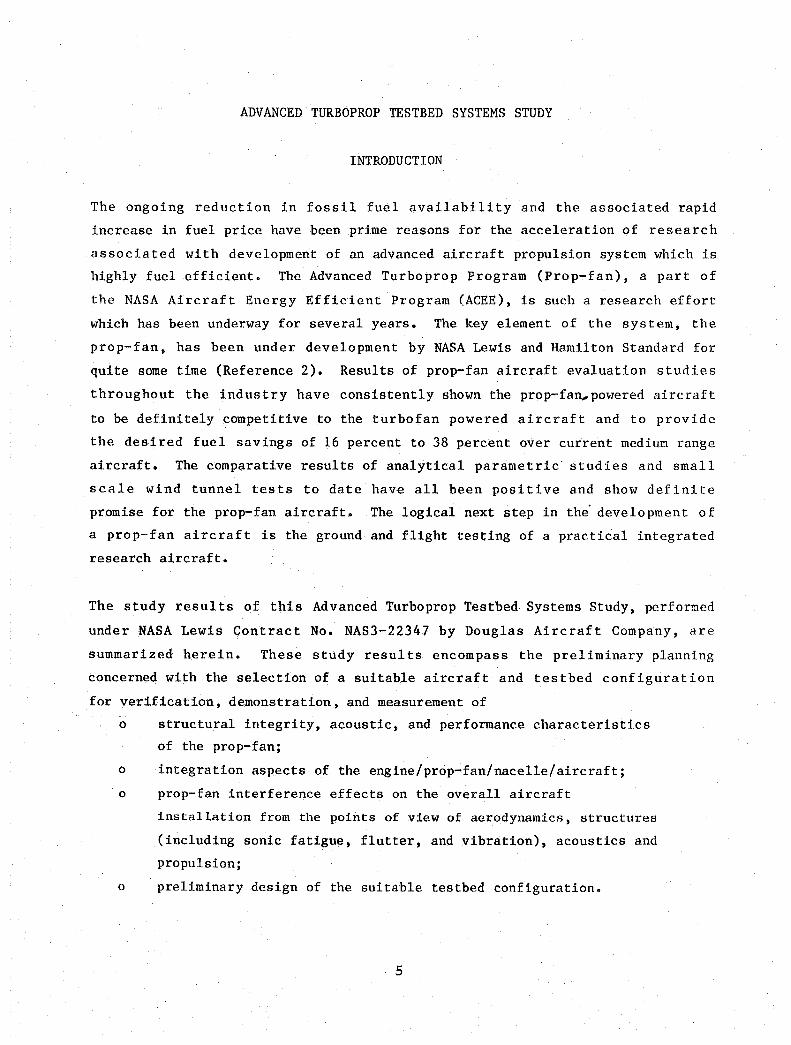
The ongoing reduction in fossil fuel availability and the associated rapid
increase in fuel price have been prime reasons for the acceleration of research
associated with development of an advanced aircraft propulsion system which is
highly fuel efficient. The Advanced Turboprop Program (Prop-fan), a part of
the NASA Aircraft Energy Efficient Program (ACEE), is such a research effort
which has been underway for several years. The key element of the system, the
prop-fan, has been under development by NASA Lewis and Hamilton Standard for
quite some time (Reference 2). Results of prop-fan aircraft evaluation studies
throughout the industry have consistently shown the prop-fan ... powered ai.rcraft
to be definitely competitive to the turbofan powered aircraft and to provide
the desired fuel savings of 16 percent to 38 percent over current mediu~ range
aircraft. The comparative results of analytical parametric· studies and small
scale wind tunnel tests to date have all been positive and show defi.nite
promise for the prop-fan aircraft. The logical next step in the" development of
a prop-fan aircraft is the ground and flight testing of a practical integrated
research aircraft.
The study results of this Advanced Turboprop Testbed Systems Study, performed
under NASA Lewis Contract No. NAS3-22347 by Douglas Aircraft Company, are
summarized herein. These study resul ts encompass the preliminary planning
concerned with the selection of a suitable aircraft and testbed configuration
for verification, demonstration, and measurement of
o structural integrity, acoustic, and performance characteristics
of the prop-fan;
o integration aspects of the engine/prop-fan/nacelle/aircraft;
o prop-fan interference effects on the overall aircraft
installation from the points of view of aerodynamics, structures
(including sonic fatigue, flutter, and vibration), acoustics and
propulsion;
o preliminary design of the suitable testbed configuration.
5

Wind tunnel testing and flight testing of the testbed configurations are taken
jnto consideration; and ROM costing and preliminary scheduling are included.
The Douglas study is performed with Hamilton Standard and Detroit Diesel
Allison as subcontractors, respectively, on the prop-fan characteristics
(design, installation, operation, performance) and on the engine (hardware,
installation, performance). Both subcontractors are highly concerned with the
efficient integration of the overall propulsion system.
As this contract study progressed, the emphasis or primary direction of the
study evolved in accordance with the pertinent engineering results. These
changes of direction of the contracted study were done in agreement with the
NASA Lewis Project Manager. The chronological variations in the study
investigation are noted as follows. First, as per the original contract, the
study parametrics included
o one selected testbed aircraft configuration;
o two candidate prop-fan propulsion system designs;
(engine/gearbox plus prop-fan);
o one prop-fan nacelle installation.
Second, as the prop-fan propulsion systems investigation showed definite
superiority of one over the other, the study emphasis changed to
o one selected testbed aircraft configuration;
o one prop-fan propulsion system design;
o one and two prop-fan nacelle installations.
Third, further investigation resulted in the evolution to the following set of
configuration conditions
o one selected testbed aircraft configuration;
o one prop-fan propulsion system design;
o two prop-fan nacelle installations.
The study results summarized herein are concerned with the Douglas DC-9
aircraft modified as a prop-fan testbed by the addition of an appropriate
prop-fan/ engine/nacelle installation on the aircraft as shown in Figures 1 and
2. The use of the Douglas DC-9 in a flight research program provides a
6

FIGURE 1. DC·9·10 PROP·FAN RESEARCH AIRCRAFT ONE PROp·FAN NACELLE CONFIGURATION
FIGURE 2. DC·9·10 PROP·FAN RESEARCH AIRCRAFT
TWO PROP·FAN NACELLE CONFIGURATION
7
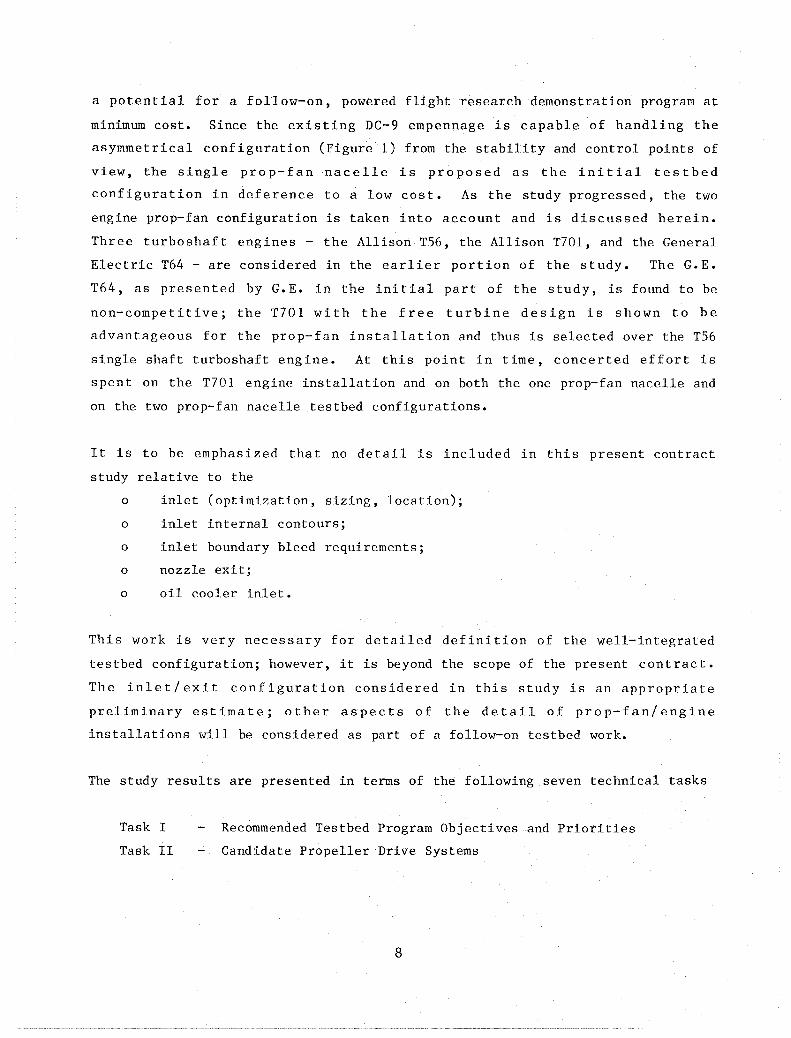
a potential for a follow-on, powered flight research demonstration program at
minimum cost. Since the existing DC-9 empennage is capable of handling the
asymmetrical configuration (Figure 1) from the stability and control points of
view, the single prop-fan nacelle is proposed as the initial testbed
configuration in deference to a low cost. As the study progressed, the two
engine prop-fan configuration is taken into account and is discussed herein.
Three turboshaft engines - the Allison T56, the Allison T701, and the General
Electric T64 - are considered in the earlier portion of the study. The G.E.
T64, as presented by G.E. in the initial part of the study, is found to be
non-competitive; the T701 with the free turbine design is shown to be
advantageous for the prop-fan installation and thus is selected over the T56
single shaft turboshaft engine. At this point in time, concerted effort is
spent on the T701 engine installation and on both the one prop-fan nacelle and
on the two prop-fan nacelle testbed configurations.
It is to be emphasized that no detail is included in this present contract
study relative to the
o inlet (optimization, sizing, location);
o inlet internal contours;
o inlet boundary bleed requirements;
o nozzle exit;
o oil cooler inlet.
This work is very necessary for detailed definition of the well-integrated
testbed configuration; however, it is beyond the scope of the present contract.
The inlet/exit configuration considered in this study is an appropriate
preliminary estimate; other aspects of the detail of prop-fan/engine
installations will be considered as part of a follow-on testbed work.
The study results are presented in terms of the following seven technical tasks
Task I
Task II
Recommended Testbed Program Objectives and Priorities
Candidate Propeller Drive Systems
8

Task III
Task IV
Task V
Task VI
Task VII
Candidate Testbed Aircraft
Testbed System Evaluation and Recommendations
Conceptual Design of Testbed Systems
Testbed Flight Test Program Plan
Wind Tunnel Test Program Plan
It is to be emphasized that the above-mentioned seven tasks are not discrete
but are mutually dependent. Therefore, some repetition among the tasks occurs
in the discussion of these report results.
A Task VIII included in the study contract covers the reporting, summarization,
and briefings of the study results.
The discussion of the results of this study is organized as per the seven tasks
noted. The section on ROM costing follows the discussions of Task VII. The
principal numerical results of the study are presented in English units. The
associated metric units are presented as secondary values and are enclosed in
parentheses, ( ).
Appendix I summarizes the characteristics of the pertinent wind tunnels.
Although not a part of the contract work statement, the work breakdown
structure, through .the second level, for the flight test testbed program is
summarized in Appendix II. Appendix III includes description of pertinent
components of the Douglas Flight Test Facility_
9 /


This Page Intentionally left Blank

TASK I
RECOMMENDED TESTBED PROGRAM OBJECTIVES AND PRIORITIES
GENERAL
The prop-fan analysis and associated aircraft design studies which have been
performed to date have shown that the prop-fan is a feasible and a viable
propulsion system which should be capable of providing fuel efficient aircraft
operation by 1985-1988. To date, the Advanced Turboprop Program which is a
part of the Aircraft Energy Efficiency (ACEE) Program has encompassed
o design, analyses, and small scale wind tunnel testing of the
prop-fan;
o low speed wind tunnel testing and analysis of critical aspects of
prop-fan/aircraft integration - for instance - aerodynamic aspects of
propeller slipstream effects including swirl, design procedures to aid
in swirl recovery, powered semi-span model which simulates the
wing/nacelle/prop-fan slipstream interaction.
Continued effort, either through wind tunnel testing or flight testing, is
required in the rapid develpment of the prop-fan aircraft. The testbed program
capable of verifying the prop-fan and its integration into a full scale
aircraft is the next step in establishing confidence in this overall prop-fan
aircraft concept. The rapidly increasing price, along with the diminishing
supply, of fossil fuel has created a definite need for a fuel efficient
aircraft to be introduced into the commercial and military aircraft fleets in
the very near future. To meet this need for fuel efficient aircraft into the
fleets, the proof of concept of the prop-fan aircraft is certainly to be
expedited. Consequently, the maximum use should be made of existing suitable
hardware such as an aircraft, turboshaft engine, engine and prop-fan controls.
The existing prop-fan design work enhances the expediency required in this
necessary validation of the prop-fan aircraft.
Throughout this prop-fan testbed research aircraft program, cooperation is
required of the airframer, the prop-fan manufacturer, and the turboshaft engine
manufacturer. In the resolution of all these technologies, the airframer is
11

considered the prime integrator, with the prop-fan manufacturer cooperating
closely, and the engine manufacturer a subcontractor of the airframer. This
overall prop-fan testbed program is expected to be monitored by NASA Lewis.
Five specific critical objectives and their order of priority for the testbed
program are considered to be
o substantiation, by large scale testing, of ,the prop-fan rotor
structural integrity, the acoustic characteristics of the
prop-fan, and the performance capability of the full scale
prop-fan;
o overall substantiation of the integrated prop-fan/aircraft
acoustic characteristics including internal and external
noise levels as well as effectiveness of recommended acoustic
treatments;
o integrated prop-fan/aircraft configuration aerodynamic aspects
including such as interferences, component contouring for most
favorable lift and drag, stability and control, and overall
performance capability;
o integration of mechanical controls with the engine and prop-fan;
o integration and compatibility of the prop-fan/inlet/engine for
the testbed.
Another very important aspect in the development of a 1990 type prop-fan
aircraft is the design study, test, and substantiation of an advanced fuel
efficient turboshaft engine compatible with the timing of this future aircraft.
This effort is necessarily that of the engine manufacturer in coordination with
the airframer. Since the testbed itself does not consider an advanced
turboshaft engine in its initial task of proof of concept of the prop-fan,
discussion of this advanced turboshaft engine is not included herein as part of
this testbed discussion. It is to be emphasized however that this development
of the advanced turboshaft engine is particularly important to the overall
prop-fan aircraft project.
Discussion follows of these above-mentioned five critical testbed program
objectives. These five objectives are discussed briefly under major headings
in Task I. Both large scale wind tunnel and flight testing are considered
12

herein as means of satisfying these objectives. However, a survey of pertinent
wind tunnel facilities, done during this study and reported in Task IV and Task
VII, show their inadequacy to provide the concept substantiation required.
LARGE SCALE PROP-FAN ROTOR TEST OBJECTIVES
The substant ia t ion of the structural integrity and performance of the prop-fan
is basic to the continued design and development of the prop-fan aircraft. All
analytical and small scale test development work on the prop-fan have shown the
prop-fan to be feasible and very worthwhile for further developmental and proof
of concept work. Hamilton Standard identifies and defines the following
technical objectives and priorities for a testbed program in the areas
associated with the prop-fan rotor. Resolution of these objectives, either
through a testbed aircraft flight research program or a large scale wind tunnel
test, will enhance industry acceptance of the prop-fan for commercial or
military aircraft designed for cruise speeds of Mach 0.8 at altitudes greater
than 30,000 feet (9144 m). As part of the NASA program, the small scale model
technology already developed for the prop-fan must be extended to full scale,
such that confidence of this prop-fan concept is established. Specifically,
the areas of structural dynamics, acoustics and vibrations, and aerodynamic
performance will be addressed, in that order of priority.
Structural Dynamics
In order to establish the most accurate test data and not precipitate
additional analytical correlation studies, the large scale prop-fan should
exhibit a blade diameter of approximately 8 to 10 feet (2.44 to 3.05 m). The
selection of an 8 to 10 foot (2.44 to 3.05 m) diameter for the testbed stems
from two considerations:
o Accurate representation of the total blade airfoil mass and stiffness
distribution, in the spanwise and chordwise directions, as well as the
proportioning of the mass and stiffness contributions of the elements
making up any given cross section of blade airfoil;
13

o accurate representation of size, shape and thickness of the blade
construction elements, so that a clear demonstration of full size
fabrication feasibility can be made
The results of the SR-3, SR-5, and SR-6 aero-acoustic model designs have
demonstrated that the thin, swept blade shape increases the degree of mass
stiffness interaction due to rotation and vibration. The response of a blade
to integer order excitation is related to its frequency and damping. The
frequency is determined by the mass and stiffness distribution; the damping is
related to the deflection amplitude and, therefore, the stiffness. The
probability of non-integer order response is related to the relative magnitude
of the airloads and blade inertia and to the separation of torsional and
bending frequencies. The blade inertia, relative location of the blade
frequencies, steady deflections of a rotating blade caused by body forces, and
aerodynamic forces are all determined by the mass and stiffness distribution.
The integer order response, freedom from non-integer order response
(flutter),and predictable deflection characteristics are essential elements of
a full scale demonstration.
The accuracy of simulation of a full scale prop-fan blade is size dependent
because the full size blade will be made of several materials of different
density, in order to provide a viable total weight. Since there are practical
limitations on the thinness of blade parts, both from a fabrication and a
durability standpoint, it is not possible to simulate full size cross sectional
properties in sub-scale size. For example, in order to withstand airloads,
buckling, panel flutter and FOD with a hollow blade tip cross section, the
minimum required pressure side skin thickness would be .060 to .080 inches
(.152 to .203 cm). If this thickness were scaled directly with prop-fan
diameter from 10 feet (3.05 m) to 2 feet (.610 m), the skin thickness would be
.012 to .015 inches (.034 to .038 cm). Since most composite lamina are about
this thickness, multi-layer laminates, which are necessary to achieve required
strength and stiffness properties, are thus ruled out. Fabricating a blade skin
from such thin sheet metal would require completely different techniques than
would be applied to a full scale blade.
14

In the retention area, similar scaling limitations are encountered. An
anti-friction bearing is required for variable pitch. The area available for
the retention and pitch control mechanism is fixed by the hub-to-tip diameter
ratio required for aerodynamic performance. The cross section of anti
friction bearings and pitch control elements such as gears, ball screws, links,
rod ends, slider blocks, etc., do not scale down well below a certain point
because of fabrication and durability characteristics.
From the Hamilton Standard design work on SR-3, SR-5 and SR-6, all of which had
solid metal blades without anti-friction retention bearings, Hamilton Standard
judges that an accurate demonstration of dynamic behavior and fabrication
feasibility could not be achieved in less than an 8 to 10 foot (2.44 to 3.05 m)
diameter prop-fan.
There are two technological areas that require validation: namely,
o the vibratory response to aerodynamic flow fields, and
o the stall and classical flutter characteristics. This evaluation
should be conducted in the order of priority indicated.
Blade Dynamic Response Validation.
Blade dynamic response is a function of the aerodynamic flow field, the blade
aerodynamic characteristics, and the blade structural dynamic characteristics.
The small model wind tunnel tests will give fairly ~ood insight into the first
two items, but will not simulate the structural dynamic characteristics of
large, spar/shell blades. Response tests on a large scale prop-fan will
provide the means for assessing the construction effects pertaining to the
aerodynamic and dynamic characteristics. The object of this subject testbed
program is to confirm the excitation loadings, predicted by the small model
tests, in the presence of an aircraft and to assess the structural response of
a large scale blade of realistic construction. Because of aeroelastic effects,
it is possible that the large scale model blades may have different stress
sensitivity than that shown on the small solid model blades. Although the IP
stress sensitivity can probably be better evaluated in a high speed wind tunnel
under controlled conditions with better instrumentation, it is believed that a
flying test bed will be the best method for evaluating the excitation effect
and overall response of prop-fan blades.
15

In order to generate the proper flow field, the vibratory response testing must
include a swept wing, a nacelle and a fuselage, at the sizes representative of
a proposed full scale aircraft. Thus, the testing of the large scale prop-fan
in a wind tunnel is precluded. Meaningful testing must include aircraft speeds
from static to 0.8 Mach number, full variation of ground wind velocities and
direction with a representative propeller thrust, full wing angle of attack
variation - both with and without flaps - and a yaw variation.
In order to evaluate the effect that the structural dynamics have on blade
response, the measured stresses will be analyzed with regard to magnitude and
frequency. The excitations, flow field, and sensitivity will be evaluated to
determine whether they are consistent with the small wind tunnel model results
or whether aeroelastic effects are present. Additionally, the presence of
secondary stressing due to the spar/shell blade structure will be assessed.
Blade Classical Flutter Validation
The possibility of classical flutter of prop-fan blades are of concern because
of the high degree of modal coupling due to the sweep and low aspect ratio, the
relatively low first torsional mode frequency, and the high operating tip
speeds. The susceptability of a blade to classical flutter is dependent on
both the aerodynamic and structural characteristics of the blade. Although
small model blades duplicate the aerodynamic characteristics reasonably well,
they do not duplicate the structural characteristics. Thus, to develop
confidence that classical flutter will not be a problem, classical flutter
tests should be run on large-scale model blades of typical spar/shell
construction. Only in this way will the true aeroelastic effects be properly
duplicated.
During classical flutter tests, the need to continuously control and measure
the operating conditions and stresses accurately requires that testing be
conducted in a high speed wind tunnel rather than on a flying test bed. A wind
tunnel would permit running at higher MN without undue concern over safety.
16

For such tests there is no need for any aircraft structure, except possibly the
nacelle, so that wind tunnel operation is practicable. Stress levels and
frequencies will be monitored for indications of the approach of classical
flutter (Random Decrement Method) over the full range of aircraft speeds from
static to 0.8 MN, and must cover the full power loading (SHP/D2) range. The
results should give confidence that the full scale, spar/shell configuration
prop-fan blades will be free from classical flutter, as well as the degree of
margin to be expected. The results will also give an understanding of the
various operating conditions on stability margin. Additionally, with a
comparison of the small model results, a feel for the construction and geometry
effects on classical flutter can be obtained.
Blade Stall Flutter Validation.
Prop-fan blades are highly loaded and stalled to a great degree during static,
very low speed, and reverse. Consequently, they are susceptible to stall
flutter, which is a function of both the aerodynamic and the structural dynamic
characteristics of the blade. In order to duplicate the true aeroelastic and
geometric characteristics, as well as the torsional frequency, the use of a
large scale model blade is desirable. As stated previously, small solid model
blades duplicate aerodynamic characteristics reasonably well, however, their
structural characteristics can only be approximated. Therefore, th~ flutter
results obtained, if this technique is utilized, would primarily be used for
evaluating theoretical prediction methods.
Since stall flutter usually is most likely to occur during static, high power
operations, an open test stand is the simplest and most effective way for its
evaluation. However, because of the high degree of stall of the prop-fan
blades, and the recent blade system flutter experience during reverse thrust on
the OVI0 aircraft, it appears that the best way for an overall stall flutter
stability evaluation of a large scale size model prop-fan would be the flying
testbed. The flying testbed allows the flexibility for evaluating not only
static operation, but also reverse and forward operation at low air speeds.
17
Analysis indicates that for these highly stalled blades, stall flutter might
occur at low forward speeds rather than statically. By monitoring the blade
torsional stressing for various operating conditions (power, RPM and airspeed),
it is possible to estimate the stall flutter boundary. By utilizing the Random
Decrement Method, it is also possible to predict the proximity to stall
flutter. This method will determine the blade torsional damping for each
operating condition.
The results will provide confidence that full scale, spar/shell configuration
prop-fan blades will be free from stall flutter, and will determine the degree
of flutter margin. The results will also provide an understanding of how the
operating conditions affect stall flutter margin. If small model tests are
run, some insight can be obtained as to the effects of construction and
geometry on stall flutter and the predictions can be checked out.
Since the blade structural response and stall flutter characteristics are best
obtained on a flying testbed, and the classical flutter characteristics can be
obtained either in a large high-speed wind tunnel or on a testbed, it is
recommended that stability testing be performed on the testbed aircraft for
complete validation.
Acoustics
Acoustics technology needs are described below •. In general, magnitude and
phase characteristics of the prop-fan noise impinging on the fuselage surface
must be established on a large-scale flight vehicle during various operating
conditions. Furthermore, the manner in which this noise is transmitted to the
interior must be understood in order to design efficient cabin noise control
treatment. An additional area in which more information is required is the
definition of prop-fan far field noise for flyover noise certification and
community noise evaluations.
18

These technology needs can be described in further detail as follows. The
noise field on the fuselage surface must be identified for both ground and
flight operation conditions in order to fully evaluate the cabin acoustic
environment. The design condition for the cabin acoustic environment, however,
will be the cruise condition. Variables that will affect acoustic loading on
the fuselage include aircraft altitude, airspeeds, and angle of attack, blade
loading and pitch angle, and prop-fan rotational speed. The effect of all
these variables on fuselage acoustic loading must be evaluated in flight on the
testbed aircraft. In addition, source noise reduction concepts such as
prop-fan synchrophasing and opposite rotation should be investigated. The term
.. synchrophasing" refers to the ability to synchronize the propellers such that
a pre-selected relative phase angle is maintained between the blades of one
propeller and the blades of any other propeller on the aircraft.
Traditional propeller synchronization by mechanical governing is necessary to
prevent acoustic beats in the cabin due to slight differences in rotational
speeds between the various propellers. Recent advances in synchronizer
technology have shown that with precision synchrophasing, not only can acoustic
beats be prevented, but an overall reduction in total noise entering the cabin
is possible. Synchrophasing has been demonstrated to provide noise reduction
in tests conducted on existing propeller aircraft. The amount of reduction and
the ability to achieve the necessary synchrophasing accuracy have not been
demonstrated yet on a prop-fan aircraft, but it is considered to be a viable
concept and should be evaluated on the testbed aircraft.
Prop-fan opposite rotation is another noise reduction concept which should be
evaluated on the testbed aircraft. It is hypothesized (based on measurements
in existing turboprop aircraft) that opposite rotation will reduce noise levels
in the cabin because the blades will sweep by the fuselage on their upward path
(for up-inboard rotation) where they are more lightly loaded aerodynamically.
Furthermore, the area of shock impingement on the fuselage would be below the
floor, as opposed to the window belt area for down-inboard rotation.
19

Noise transmission through the fuselage and interior panels must be understood
in order to design effective noise control treatment. Analytical procedures
designed to predict this transmission must be validated with experimental data
in full scale using a realistic high- speed transport-type structure with
appropriate acoustic treatment. Large scale (narrow-body transport size)
validation is necessary because scaling from small size to full size models is
important to the performance of acoustic treatment designs. Noise transmission
properties of the fuselage and acoustic treatment materials cannot be scaled
without the introduction of a high degree of uncertainty, which would adversely
impact the accomplishment of the stated program objectives.
Initial validation of the analytical models can be accomplished in a flight
test program on an existing turboprop. Such a program, with appropriate
pre-test and post-test analyses, could be used to verify the predicted
transmission loss of the fuselage shell as well as the performance of advanced
acoustic treatment designs. Due to the cost of modifying a fuselage, this test
program would probably be limited to add-on types of acoustic treatment.
Presumably, several acoustic treatment designs would be initially evaluated in
a laboratory test set-up before installation in the aircraft.
The definitive validation of all prediction models and acoustic treatment
designs should be done on a prop-fan powered transport-type aircraft capable of
cruising at 0.8 Mach. This testbed prop-fan installation should be as similar
as possible to a production prop-fan installation; i.e., the prop-to-fuselage
tip clearance should be approximately 0.8 prop diameters; a two prop-fan
installation should be used; and a realistic inlet/nacelle/wing configuration
should be utilized. Furthermore, the noise of the prop-fans should not be
contaminated by extraneous noise from other propulsors on the aircraft. In
other words, the aircraft layout, power requirements, and operation must be
arranged in such a way as to minimize contamination of the prop-fan sound
signal by turbofan noise.
20

In addition to measurement of near field prop-fan noise on the fuselage and
interior noise, the testbed aircraft may also provide an opportunity to measure
far field noise during simulated takeoff and approach conditions. These data I
are needed in order to make noise predictions at the FAR Part 36 measurement
points. Current far field noise prediction procedures for the prop-fan require
substantiation by test data. These noise measurements cannot be accomplished
under static test conditions because of the present lack of understanding of
the use of static test data. Although previous work has been done in
permitting wind tunnel noise measurements to be used to predict far field
noise, predictions obtained in this manner on a large scale propeller should be
augmented by flight data.
Performance
The main objective is to confirm the performance by evaluating a prop-fan of
large scale size, such as 8-10 feet (2.44-3.05 m), and shape with a realistic
nacelle configuration at the critical design conditions (i.e. efficiency,
pressure, velocity distribution, swirl, etc.). Altitude and Reynolds number
are not considered to be an issue. Testing should be performed in a wind
tunnel, over the full Mach number range with a wide variation in power loading
and tip speeds.
In the field of performance, there are three technological needs that should be
investigated: namely, the validation of the aerodynamic performance; the
evaluation of the installation effects and; nacelle and inlet configuration
definition. All of these technological needs can best be met in a wind tunnel
test and in the order of priority indicated.
The last two items should be investigated in model scale rather than full scale.
Aerodynamic Performance Validation.
The prop-fan performance levels established by the small model tests conducted
under the NASA Advanced Turboprop Project are expected to be achieved by the
full-scale prop-fan. However, a performance test on a large scale prop-fan is
important to confirm the expected performance and to provide data for designing
future configurations with improved efficiency.
21
Since the controlled conditions in wind tunnel testing have proven to provide
more accurate and repeatable measurements than is possible from flight tests,
this performance confirmation test should be accomplished in a large-scale,
high-speed wind tunnel. In fact, the same hardware to be used in the
structural and acoustic flight test later may be used in a wind tunnel.
The performance measurements from this test with actual full scale flight test
hardware, (i.e. prop-fan, nacelle without the wing) are important since these
data will include such effects as surface smoothness, manufacturing tolerances,
spinner-to-blade juncture, aeroelastic deflections under operating loads and
full scale Reynolds number, etc. These above-mentioned shape effects are not
included in the existing model test data. The complete performance spectrum of
interest should be defined in this wind tunnel test. Accordingly, the test
schedule should cover a tunnel Mach number range from near static through 0.8 -
0.85 for a wide range of power loading at tip speeds from 500 (152) through 900
ft/sec (274 m/sec). Reverse thrust performance, windmilling and feather drags
should be investigated as part of the test program.
Installation Effects Evaluation
The effect of the prop-fan and nacelle interaction may require that the wing be
modified to accommodate the prop-fan slipstream with no significant performance
penalty. The basic investigation should be conducted in the wind tunnel on a
small scale, semi-span model. This program is required to provide aerodynamic
data for establishing the "optimum" nacelle location on the wing, the nacelle
and wing interface geometry, and the wing modifications required to maintain or
improve wing performance in the presence of the prop-fan slipstream.
The large-scale flight test vehicle will not be preferrred for acquiring the
detailed data needed for the production design because the testbed wing is not
a supercritical wing of the type anticipated for the produdction aircraft, the
propeller/wing size relationship is incorrect, and the thrust minus drag data
is not as accurate as can be obtained in a wind tunnel with a strain-gage
balance. However, the overall aircraft performance obtained from flight test
data can provide information for assessing the overall propulsive efficiency.
22

In this case, the performance measurements should be made on an aircraft
designed for a prop-fan propulsion system rather than a flying testbed where
the prop-fan engine provides a small portion of total thrust.
A more precise means of establishing propulsive efficiency would be from wind
tunnel measurements on a large scale prop-fan and nacelle installed on a
semi-span aircraft model. However, the tunnel size and scale effects to
obtain proper wing performance becomes a question. The airframe manufacturer
is best qualified to recommend the wing size and wind tunnel for this
evaluation. For the best installation, the wing and fuselage forces should be
measured on a balance separated from the prop-fan and nacelle forces. The
prop-fan data should be obtained from thrust and torque meters installed in the
nacelle and, finally, the friction drag on a nacelle should be measured on a
separate nacelle balance. In this manner the effect of prop-fan slipstream on
the aircraft components may be established as well as the performance of the
prop-fan in the presence of the aircraft. These detailed measurements could
not be made on any practical flight test vehicle.
Nacelle and Inlet Configuration Definition
The shape of the nacelle integrated with the prop-fan is important to achieving
high efficiency at high flight Mach numbers. The prop-fan models tested to
date have incorporated a carefully configured nacelle to minimize blade root
Mach numbers thereby reducing compressibility losses. However, neither the
effect of nacelle shape on aircraft performance nor the effect of engine air
inlet shape on prop-fan performance and inlet pressure recovery have been
investigated •. This research task should be conducted in the wind tunnel on
small models. When an optimum nacelle/inlet configuration has been
established, a large-scale wind tunnel test should be performed to determine
the efficiency, nacelle drag, and inlet pressure recovery. For the flight
research program, the inlet pressure recovery should be measured. even if the
nacelle and inlet shapes are not optimized configurations, in order to
establish inlet pressure recovery levels actually achieved by the prop-fan
inlet at high Mach numbers and Reynolds' number.
23
Summary of Prop-fan Testbed Program Priorities
Assessment of the priorities for the testbed program objectives is based on the
relative importance of the structural integrity, acoustic environment and
aircraft performance technological areas.
The areas of technological need can be summarized as indicated below:
Priority 1 Integrity of the prop-fan structure which includes the vibratory
response to aerodynamic flow fields, the prop-fan stall, and classical flutter
boundaries.
Priority 2 Passenger cabin acoustic and vibration environment. Areas of
concern are:
o evaluation of prop-fan acoustic loads on the fuselage, including the
effects of prop-fan synchronization and opposite rotation, and
o effectiveness of sidewall acoustic treatment in reducing prop-fan
noise transmitted to the interior.
Priority 3 Aircraft performance, although important, should not jeopardize
satisfying the more important structural integrity and acoustic requirements.
The performance areas of concern are validation of the aerodynamic performance,
evaluation of the installation drag effects, and definition of the nacelle and
inlet performance.
TESTBED ACOUSTIC OBJECTIVES
In order to gain acceptance of the prop-fan as a propulsor for commercial
aircraft, an acceptable solution to the interior noise problem must first be
demonstrated to the customer airlines. Questions that should be addressed in
the area of acoustics include:
o Can interior noise and cabin vibration levels be obtained in prop-fan
aircraft that are comparable to the levels in present turbofan
aircraft?
24

o What is the weight penalty associated with attaining low interior
noise levels and how does this weight penalty affect operating costs?
o Can prop-fan aircraft meet present and future flyover noise
regulations?
This study will investigate the ability of either a flying testbed aircraft or
a wind tunnel test program to provide answers to these questions. It is not
anticipated that either test program would completely answer all of the
questions, however, the relative merits and shortcomings of each program will
be discussed.
Measurement of the noise generated by a large scale prop-fan during flight
conditions is necessary in order to determine acoustic levels and directivities
in both the near and far field. The near field information will provide input
for fuselage structural design to prevent sonic fatigue, and for acoustic
treatment design to reduce interior noise. These tasks require precise
definition of the external noise field acting on the fuselage in order to
attain maximum design effectiveness at minimum weight penalty. Present
propeller noise prediction procedures and model propfan wind tunnel test data
are useful for preliminary design studies, but require verification before more
detailed design work is performed. The accuracy of existing prediction
procedures remains in question, as does the effect of scaling model prop-fan
wind tunnel data to full scale propellers. It is anticipated that noise data
from the testbed program will provide the means for verification or
modification of the prediction procedures.
Measurement of far field noise is needed to show the ability of a prop-fan
powered aircraft to meet present and possible future flyover noise regulations.
Current procedures for prediction of prop-fan far field noise require
verification before they can be used with any degree of confidence. Accurate
far field noise estimates will be needed before guarantee discussions can take
place with customer airlines.
25

The task of designing acoustic treatment to reduce interior noise requires that
measurements of fuselage vibration and cabin noise be made first without any
acoustic treatment, so that the noise reduction afforded by the fuselage can be
determined. The difference between the cabin noise level without any acoustic
treatment and the interior noise goal will be the amount of noise reduction
that must be provided by the treatment.
Measurement of fuselage vibration and cabin noise will also provide a means for
evaluation of the structural response analytical models that are used to
predict interior noise levels. The data will show how the structure responds
to the external noise field and how it radiates the noise to the interior.
The testbed aircraft will also be used to test the effectiveness of various
acoustic treatment designs. The actual performance of several trim panel and
sidewall cavity treatment configurations can be compared against predicted
performance and the performance required to meet the interior noise goal. It
is important that the ability of an acoustic treatment design to meet the
interior noise goal be demonstrated to gain airline customer acceptance. These
data will also provide the information necessary to compute the minimum \veight
penalty actually needed to attain the desired interior noise level.
As a byproduct of the testbed program, data will be available to determine the
effects of scaling model prop-fan wind tunnel data to a large scale propeller.
Determination of scaling effects would make existing model prop-fan data much
more useful and also may enable future model prop-fan test data to be used for
parametric studies of full-scale designs.
To summarize the previous discussion, the acoustic objectives of the testbed
program are listed here in order of importance:
o Measure prop-generated near field and far field noise during
representative ground and flight conditions.
26

o Measure passenger cabin noise and fuselage vibration during cruise
flight conditions.
o Determine the effectiveness of various types of noise control
treatment in reducing passenger cabin noise.
o Evaluate prop-fan opposite rotation and synchronization effects.
o Determine the effects of scaling model prop-fan noise data to large
scale applications at representative flight conditions.
o Obtain data to verify or modify existing theoretical prediction models.
o Obtain data to develop procedures for predicting FAR Part 36 noise
levels.
Resolution of Acoustic Objectives
The resolution of acoustic objectives may be accomplished by testbed aircraft
or by wind tunnel testing. The following discussion addresses these two
methods.
Resolution by Testbed Aircraft.
A flying testbed aircraft will provide a highly desirable means of
accomplishing most of the acoustic objectives listed above. A flying testbed
will provide the direct means for verification of the various prediction
procedures that are currently being relied upon rather heavily; and in
addition, it will provide an opportunity for potential customer airlines to
witness a large scale prop-fan installation. The ability to attain acceptable
interior noise levels can also be demonstrated.
27

Regarding the ability of the testbed program to accomplish the stated acoustic
objectives, measurement of near field noise levels and directivity can be
accomplished by means of an array of external microphones flush-mounted to the
fuselage skin. Precise definition of the external noise field during flight is
needed to formulate detailed predictions of fuselage response. The external
microphone array will be designed to measure the levels and spatial
characteristics of the external noise field, including relative phase. The
microphone signals will be recorded simultaneously on a multi-track recorder so
that phase information can be obtained through appropriate data analysis.
It is desirable to measure prop-fan generated far field noise with the testbed
aircraft. Normally, the preferred method of accomplishing this would be to
conduct actual takeoffs and approaches. However, the proposed testbed aircraft
is currently restricted to operation at altitudes above 15,000 feet (4572 m).
The 15,000 foot (4572 m) altitude restriction may be removed if wind tunnel
testing verifies that the testbed aircraft can be operated safely at lower
altitudes. Noise measurements may thus be obtained in a low-altitude level
flyover, or in a low-al ti tude descent. These noise measurements may then be
used to validate or improve the prop-fan far field noise prediction methods,
which can then be used to estimate the aircraft's noise characteristics for
other flight conditions.
Alternatively, far field noise data may be obtained under forward speed
conditions during taxi testing. It is suggested that noise measurements during
taxi tests be included in the testbed program even if it is determined that
level flyovers are possible. The taxi tests will provide backup data in the
event that the flyover data quality is poor. The taxi measurements also have
the advantage of being uncontaminated by turbofan noise. Furthermore, the taxi
data can be used for comparisons with the flyover data and ground static data
to obtain a better understanding of the effects of forward speed on propeller
noise.
28

The ability to use propeller noise measured under ground static conditions will
become a necessary part of any future production program. The prop-fan testbed
aircraft will provide an opportunity to obtain both ground static data and data
under forward speed conditions (either during level flyovers or taxi testing,
or both). As discussed later in this report, the problems associated with the
interpretation of static propeller data may not be insurmountable and,
therefore, these measurements should be obtained as part of the testbed
program. In addition, far field noise measured during ground static runup will
yield information useful for airport community noise assessment for ground
operations prior to brake release.
Prop-fan near field noise will be measured using the fuselage flush- mounted
microphone array during ground static, taxi, and flight operations. In
addition to characterizing the prop-fan noise field on the fuselage under these
conditions, the data can be combined with accelerometer and interior microphone
data to identify fuselage response and transmission loss.
Passenger cabin noise will be measured using microphones located both near the
sidewall and at the center of the aircraft at appropriate locations along the
length of the cabin. Cabin noise will be measured for both treated and
untreated (barewall) sidewall configurations. The barewall measurements will
permit determination of fuselage noise reduction, when compared to the noise
levels measured by the exterior microphones.
Cabin noise measurements with sidewall acoustic treatment will yield data on
the noise reduction of the various treatment designs. The extent of the
prop-fan noise field in the cabin and the ability of certain acoustic
treatments to meet specific interior noise goals will be determined with the
i.nterior microphone system.
Fuselage shell vibration will be measured using accelerometers mounted on
selected skin panels and stiffeners. These data, along with the data gathered
on th8 external noise field from the fuselage flush mounted microphones, will
permit characterization of the dynamic shell response, including amplitude,
phase, skin velocity, wavespeed, and frequency response.
29

The inflight shell vibration data will be used with the barewall data from the
interior microphones to check the ability of the structure to radiate sound
energy to the interior. This property, known as radiation efficiency, is
related to skin velocity, wavespeed in the structure, and wavespeed in the
acoustic medium.
Additional tests that will be performed to identify the interior acoustic
environment include reverberation time measurements of both the barewall and
treated configurations. Reverberation times are needed in order to calculate
values of cabin acoustic absorption. Calculation of cabin absorption allows
conversion from noise reduction (a measured quantity) to transmission loss (an
acoustic property of the material) for the fuselage structure and acoustic
treatments. Assuming the inner surfaces of the various trim panel designs are
not too different, one set of reverberation time measurements will be
satisfactory for all trim panel configurations. In order to perform this test,
multiple sound sources of pink noise will be placed in the cabin. The same set
of interior microphones used for the other portions of the test program will
act as receivers.
Comparison between the interior microphone measurements with and without
acoustic treatment, in conjunction with the corresponding interior absorption
measurements, will permit determination of the effectiveness of the various
acoustic treatment designs that are tested.
There are several potentially important noise and vibration transmission paths
from the prop-fan system to the aircraft interior. These include
structure-borne transmission paths, which are not addressed in this study,
however, this subject will be addressed in future work.
For the major portion of the testbed program, acoustic treatment designs will
all be of the type known as "add-on"; I.e., not requiring modification of the
primary fuselage structure. The only modifications that will be made to the
basic structure will be for prevention of failure due to sonic fatigue. These
necessary structural modifications will probably be accomplished by the
addition of frame and longeron sections, an increase in skin gauge, or the
addition of skin doublers in the vicinity of the prop plane.
30

Acoustic treatment designs to be included in the testbed program will be
designed to be interchanged with or added to existing trim panel structure or
blanket systems. Approaches that will be evaluated include increased trim
panel mass and stiffness, use of honeycomb trim panels, increased skin-to-trim
panel distance, damping added to skin panels, and introduction of limp mass
into the blanket system. A later portion of the testbed program will involve
the testing of an acoustic treatment design which requires modification of a
section of the basic fuselage structure. The advanced treatment may consist of
isogrid outer structure, modified standard structure, or possibly some other
concept. The advanced treatment concept to be used on the testbed aircraft
will be selected based on results of laboratory acoustic treatment development
testing.
Determination of the effects of scaling model prop-fan near field noise data to
large scale applications can be accomplished using data from the flying testbed
program. It is especially desirable to scale the model prop-fan data to data
acquired during flight because the effects of pressure, temperature, flow
field, and forward speed will all be present in the flight data.
Acoustic objectives of this study that can be accomplished by a flying testbed
program are as follows:
o Measurement of prop-fan near field and far field noise.
o Measurement of passenger cabin noise and fuselage vibration.
o Determination of the effectiveness of various types of acoustic
treatment.
o Determination of the effects of scaling model prop-fan noise data to
large scale applications at representative flight conditions.
31

The only acoustic objective of this study that cannot be accomplished in the
flying testbed program is the measurement of prop-fan far field noise during
takeoff and approach. In addition, measurement of far field noise during level
flyovers (or descent) may not be allowed because of the previously discussed
flight envelope altitude restriction.
Resolution by Wind Tunnel Testing:
Resolution of the acoustic objectives of this study by means of a wind tunnel
test program is incomplete for some of the objectives and impossible for the
others. At low Mach numbers measurement of near field noise generated by the
prop-fan is possible in a facility such as the NASA Ames 40 x 80 foot wind
tunnel. Maximum Mach number for this facility is approximately 0.45, which is
far below a cruise condition Mach number of 0.80. Furthermore, the problems of
ambient noise and tunnel wall acoustic reflections must be dealt with. The
perimeter of the test section can be lined with sound absorbing material (this
has been partially done in the past), which is expensive and relatively
ineffective at the low blade passage frequency of the prop-fan. Overspeeding
the prop-fan is not recommended because of problems in interpretation of the
acoustic data, and also it is not compatible with other nonacoustic objectives
of the test program. Acquisition of good near-field noise data inside a wind
tunnel is uncertain at best, and it is not representative of cruise flight
conditions.
The acquisition of far field noise data in a wind tunnel is even more uncertain
than the acquisition of near field noise data. Far field noise measurements
can be made in the 40 x 80 foot Ames wind tunnel for locations near the
prop-fan disc plane. Depending on the location of the propeller test rig, it
may be possible to place microphones up to 50 feet (15.2 m) away from the
prop-fan blade tips, which is 5 prop-fan diameters away from a 10 foot (3.05 m)
diameter prop-fan (the propeller far field is generally defined as beginning
approximately 3 or 4 propeller diameters from the blade tips). However, high
ambient noise levels and tunnel wall acoustic reflections may present severe,
if not insurmountable, problems to acquisition of good acoustic data.
32
Far field noise may be measured under ground static conditions on an outdoor
test rig such as the MDC QIAETsite engine test stand located in Quartsite,
Arizona. This requires a separate installation and does not include mounting
the prop-fan on a wing/fuselage section. Problems associated with the
interpretation of static propeller noise data may prevent it from being useable
without knowledge of proper data reduction techniques and adjustment factors.
These static-to-flight adjustments have to be determined based on comparison of
the static data with flight data (if they can be determined at all).
Therefore, it is doubtful that the measurement of far field noise on a static
test stand only will yield useable information.
Measurement of passenger cabin noise and vibration and the determination of the
effectiveness of noise control treatment cannot be accomplished in a wind
tunnel test program.
Assuming good near field noise data can be obtained on a 10 foot (3.05 m)
diameter prop-fan in the 40 x 80 foot tunnel, effects of scaling model prop-fan
data to large scale applications can be attempted. A problem that may be
encountered in the determination of scaling factors is that the effect of
forward speed may not be adequately represented in the 10 foot (3.05 m)
diameter prop-fan data because of wind tunnel flow speed limitations. This
factor leads to a great deal of uncertainty as to the validity of scale factors
determined from a wind tunnel test program. Testing the 10 foot (3.05 m)
diameter prop-fan in a smaller high-speed wind tunnel will not yield usable
acoustic data because of the test section space limitations.
Acoustic objectives of this study that can be accomplished by a wind tunnel
test program are, therefore, limited to the following:
o measurement of near field noise during low Mach number flow
conditions (0.45 Mach);
o measurement of far field noise in the prop-fan disc plane during
ground static conditions on an outdoor test rig (requires
separate installation);
o determination of scaling effects on near field noise at low Mach
number (0.45 Mach).
33

Acoustic objectives of this study that can not be accomplished by a wind tunnel
test program include:
o measurement of prop-fan near field noise at cruise Mach numbers;
o determination of scaling effects on near field noise at cruise
Mach numbers.
o measurement of far field noise during formal flight;
o measurement of passenger cabin noise and vibration;
o determination of the effectiveness of acoustic treatment.
In view of the numerous acoustic limitations of a wind tunnel test program, it
is highly recommended that the flying testbed program be undertaken. The
flight testing of a large scale prop-fan installation will have a much greater
ability to convince user airlines of the feasibility of operating this type of
aircraft than will results of wind tunnel testing. In addition, the flight
test program will provide very valuable information enabling building a more
efficient and quiet aircraft.
34

INTEGRATED PROP-FAN/AIRCRAFT AERODYNAMICS ASPECTS
Table 1 lists the major aerodynamic objectives required to verify feasibility
of the prop-fan installed on an aircraft. These are listed in order of
priority for each method of test (flight and wind tunnel).
TABLE I
AERO OBJECTIVES TO VERIFY FEASIBILITY
ACCEPTANCE OF PROP-FAN
Wind Tunnel Test Flight Test Large Scale
Obiectives Large Scale Partial Span Model
Aircraft Characteristics(l)
0 Speed and fuel burned X --0 Flying qualities with
power application
0 Stall characteristics (augmented thrust)
0 Downwash at tail with power on
Propulsive Efficiency(l) X --0 Thurst minus drag
0 Nacelle/wing contouring
0 Propeller inflow velocity and angle
Inlet/Engine Compatibility -- X
(1) Prefer using subscale wind tunnel tests.
35

Aircraft Charcteristics
The most important chara~teristics of a prop-fan powered aircraft are speed,
fuel burned, handling characteristics and flying qualities. Full span subscale
wind tunnel tests at both high and low speed can be used to determine the
preliminary aero characteristics and develop the details of the wing/nacelle
contouring. The advantages of subscale wind tunnel testing are
o proper engine/prop/wing size relationship;
o accurate force measurements using a balance;
o safe exploration of operational envelope;
o lower cost and less time consuming geometry modifications required to
optimize wing/nacelle shape.
There are several factors that subscale wind tunnel tests do not take into
account. These are:
o Reynolds number effects low Reynolds numbers will result in
unrealistic boundary layer displacement thickness modifying the
effective aero external lines which will affect the drag and aero
characteristics; thus premature boundary layer separations can also
occur.
o Engine inlet flow effects the subscale tests will have propeller
drive air supplied externally thus the engine inlet flow cannot be
simula ted. Therefore, inlet drag characteristics and interactions of
the inlet with the propeller and wing cannot be measured.
o Excrescence drag the drag of surface roughness, cooling airflow,
leakage, etc., can only be reasonably determined in large scale tests.
o Drag due to lift wind tunnel wall effects and low Reynolds numbers
affect the induced drag.
36

The large scale flying te~tbed will closely simulate Rynolds' numbers
experienced on the production aircraft. The flowing inlet will be present and,
since it is flight hardware, the excrescence drag and induced drag will be
properly simulated.
Propulsive Efficiency
The propulsive efficiency is defined as
n = (T-D) V 550 SHP 1
where (410.1 Kw)
T prop-fan thrust lb
D drag of installation lb
SHP shaft horsepower
V flight speed - ft/sec
The flight representative thrust minus drag (T-D) term can best be obtained
using a flight test. Technical issues are nacelle/wing drag, propeller plane
flow conditions for maximum thrust prop-fan design, and prop-fan efficiency.
High Reynolds number flight hardware roughness, and the presence of the flowing
inlet are required to obtain representative nacelle/wing drag and propeller
thrust. This can only be done at large scale using the flying testbed.
Inlet Engine Compatibility
A test of the engine inlet and measurements to establish compatibility with the
engine can be adequately performed using a partial wing span flight size model
in the wind tunnel. The inflow angle and velocity errors resulting from a
partial span wing (See Section VII for further discussion) are considered small
enough to warrant a test of this type. Large scale is important to obtain the
correct boundary layer characteristics inside the inlet duct.
37

INTEGRATION OF MECHANICAL CONTROLS WITH ENGINE AND PROP-FAN
The prime responsibility of selection of existing or modified controls for the
engine and for the prop-fan, suitable for the testbed research aircraft, is
considered that of the engine or prop-fan manufacturer in conjunction with the
airframer. In the case of the prop-fan, the controls, pitch10ck, and prop-fan
pitch control mechanisms are designed by Hamil ton Standard and are discussed
herein in Task II. The engine and the associated gearbox design and/or
modifications, unique to the turboshaft system, are the engine manufacturer's
task. In the case of the gearbox, it is felt that realistic full scale sizes
of 15,000 SHP (11,185 Kw) or under are within the present state of the art.
The question of opposite rotation of the prop-fan is one which is quite
feasible but will require modification of the gearbox. These are questions
directed to the engine manufacturer. Discussion of this activity is included
in Task II of this report.
INTEGRATION AND COMPATIBILITY OF PROP-FAN/INLET/ENGINE
The inlet design and its match to the prop-fan and engine under the required
mission operating conditions is critical to the design of a "near-optimum"
prop-fan aircraft. The scope of the testbed study as considered herein does
not include the allowance for necessry work relative to the inlet design
optimizations; this "optimization" work should be a necessary task included in
any plans for follow-on testbed work. Mach number and pressure operating
conditions ahead of the inlet but aft of the prop-fan are critical to the inlet
design. These Mach numbers and pressures are not known at this time.
Therefore, the inlet shown throughtout this study is a representation; before
the testbed is flown, the inlet placement on the aircraft, the internal and the
external inlet contours will have been properly substantiated. This work must
be done by the airframer in close coordination with both engine and prop-fan
manufacturer.
38

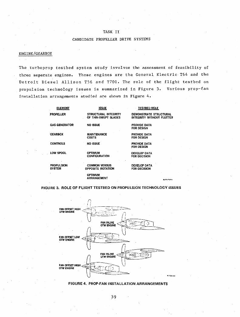
TASK II
CANDIDATE PROPELLER DRIVE SYSTEMS
ENGINE/GEARBOX
The turboprop testbed system study involves the assessment of feasibility of
three separate engines. These engines are the General Electric T64 and the
Detroit Diesel Allison T56 and T701. The role of the flight testbed on
propulsion technology issues is summarized in Figure 3. Various prop-fan
installation arrangements studied are shown in Figure 4.
ELEMENT ~ TESTBED ROLE
PROPELLER STRUCTURAL INTEGRITY DEMONSTRATE STRUCTURAL OF THIN·SWEPT BLADES INTEGRITY WITHOUT FLUTTER
GAS GENERATOR NO ISSUE PROVIDE DATA FOR DESIGN
GEARBOX MAINTENANCE PROVIDE DATA COSTS FOR DESIGN
CONTROLS NO ISSUE PROVIDE DATA FOR DESIGN
LOW SPOOL OPTIMUM DEVELOP DATA CONFIGURATION FOR DECISION
PROPULSION COMMON VERSUS DEVELOP DATA SYSTEM OPPOSITE ROTATION FOR DECISION
OPTIMUM ARRANGEMENT
8O-GEN·21~lA
FIGURE 3. ROLE OF FLIGHT TESTBED ON PROPULSION TECHNOLOGY ISSUES
FAN OFFSET HIGH OlWENGINE
SQ-GEN27591
FIGURE 4. PROP·FAN INSTALLATION ARRANGEMENTS
39
The availability of suitable gearboxes is considered in evaluation of these
engines for the DC-9 prop-fan testbed. In evaluating the engines for the DC-9
prop-fan testbed, it is determined that in each case the most appropriate
gearbox orientation is pinion low. This pinion low mounting produces a
favorable ground clearance and still provides for access to the engine,
gearbox, and accessories in the engine compartment. In each case the engine is
mounted £orward and above the wing with the engine tailpipe routed over the
wing and exhausting in the vicinity of the wing trailing edge.
In working out a control system which will meet the needs of the DC-9 prop-fan
testbed aircraft, and considering the control systems used by the three
candidate engines, it becomes clear that a suitable control system can be
devised which is not drastically different than the basic system used for each
engine. Therefore, any of the control systems of the three engines under
consideration for the testbed application can be suitably modified to fill the
needs of the test program as visualized.
Of the three engines under consideration for the prop-fan testbed program, one,
the Allison T56, is a single shaft design and the other two, the General
Electric T64 and the Allison T701, are dual shaft (free turbine) designs. In
the single shaft design the specified tip speeds of 800, 700 and 600 ft/sec
(244, 213, and 183 m/sec) can be met by varying turbine RPM. This drastically
lowers the maximum available power loading, SHP/D2, because the shaft
horsepower available is a strong function of compressor and turbine RPM. For
example, if the prop-fan is sized to produce a cruise SHP/D2 of 37.5 (301
Kw/m2) at a tip speed of 800 ft/sec (244 m/sec) at 100 percent rated engine RPM
the maximum available SHP/D2 drops to 17 (135 Kw/m2 ) when the engine speed is
reduced to produce a tip speed of 600 ft/sec (183 m/sec). As the requirements
of the testbed capability specifies a SHP/D2 of 26 (209 Kw/m2 ) at 600 ft/sec
(183 m/sec), it is obvious that either three separate gearboxes or one gearbox
with several gear changes will be required to maintain the engine at or near
its rated RPM. The alternative of sizing the prop-fan for the cruise disc
loading of 26 (209 Kw/m2) results in a smaller diameter test prop-fan.
In the case of the free turbine (dual shaft) deSign, this speed reduction does
not have such a drastic effect. Assuming, as above that the prop-fan is sized
40
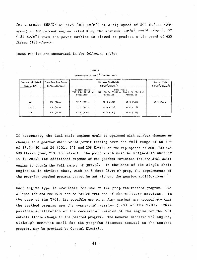
for a cruise SHP/n2 of 37.5 (301 Kw/m2) at a tip speed of 800 ft/sec (244
m/sec) at 100 percent engine rated RPM, the maximum SHP/n 2 would drop to 32
(181 Kw/m2 ) when the power turbine is slowed to produce a tip speed of 600
ft/sec (183 m/sec).
These results are summarized in the following table:
TABLE 2
COMPARISON OF SHP/02 CAPABILITIES
-----------Percent of Rated Prop-Fan Tip Speed Maximum Available Oesig
Engin e RPM Ft/Sec (m/sec) SHP /02 (Kw/m2) SHP/02
Single Shaft Oua1 Shaft -O~
T56 8 Ft (2.44 m) T701 10 Ft (3.05 m) T64 7 Ft (2.13 m) Propeller Propeller Pro~l1er -
10 0 800 (244) 37.5 (301) 37.5 (301) 37.5 (301) 37.5
8 7.5 700 (213) 22.5 (181) 34.6 (278) 34.4 (276)
5 600 (183) 17.3 (139) 32.4 (260) 31.4 (252)
If necessary, the dual shaft engines could be equipped with gearbox changes or
changes to a gearbox which would permit testing over the full range of SHP/n 2
of 37.5, 30 and 26 (301, 241 and 209 Kw/m2) at the tip speeds of 800, 700 and
600 ft/sec (244, 213, 183 m/sec). The point which must be weighed is whether
it is worth the additional expense of the gearbox revisions for the dual shaft
engine to obtain the full range of SHP/n2• In the case of the single shaft
engine it is obvious that, with an 8 foot (2.44 m) prop, the requirements of
the prop-fan testbed program cannot be met without the gearbox modifications.
Each engine type is available for use on the prop-fan testbed program. The
Allison T56 and the T701 can be bailed from one of the military services. In
the case of the T701, its possible use on an Army project may necessitate that
the testbed program use the commercial version (570) of the T701. This
possible substitution of the commercial version of the engine for the T701
entails little change in the testbed program. The General Electric T64 engine,
although somewhat small for the prop-fan diameter desired on the testbed
program, may be provided by General Electric.
41
Each engine/gearbox combination has a somewhat different mode of cooling the
oil. Each engine/gearbox oil cooler arrangement has been investigated and each
are amenable to adapt ion to the DC-9 prop-fan research vehicle. Hardware has
been identified which will suffice for the prop-fan testbed program. For
opposite rotation on the prop-fans, an idler gear must be added to the gearbox
system.
Since it is envisioned that the testbed aircraft will not be taking off and
climbing with the prop-fan engine in operation it will be necessary to provide
for a means of in-flight starting.
A typical power management schedule for the testbed aircraft, from takeoff to
test altitude and speed may be such as follows:
o begin test with feathered propeller and windmilling engine;
o start gas generator in flight at low Mach number and altitude;
o move from feather to test RPM with pitch schedule for zero thrust;
o increase pitch to test value.
The prop-fan blade angle must operate from a pitch setting for zero thrust, as
a function of RPM and Mach number, through a setting of positive thrust to a
setting for negative thrust. Safe operating conditions must be ensured
throughout the above-mentioned procedures. Two conditions in particular are of
concern, namely:
o rapid RPM changes possible from changes in blade pitch of the prop-fan
or gas generator power, (low pitch lock and negative torque system),
and
o high drag resulting from flat pitch (inflight pitch lock).
Effective safety procedures or devices useful during these operating conditions
may be
o overs peed governor
o feathering
o pitch lock
o propeller brake
42
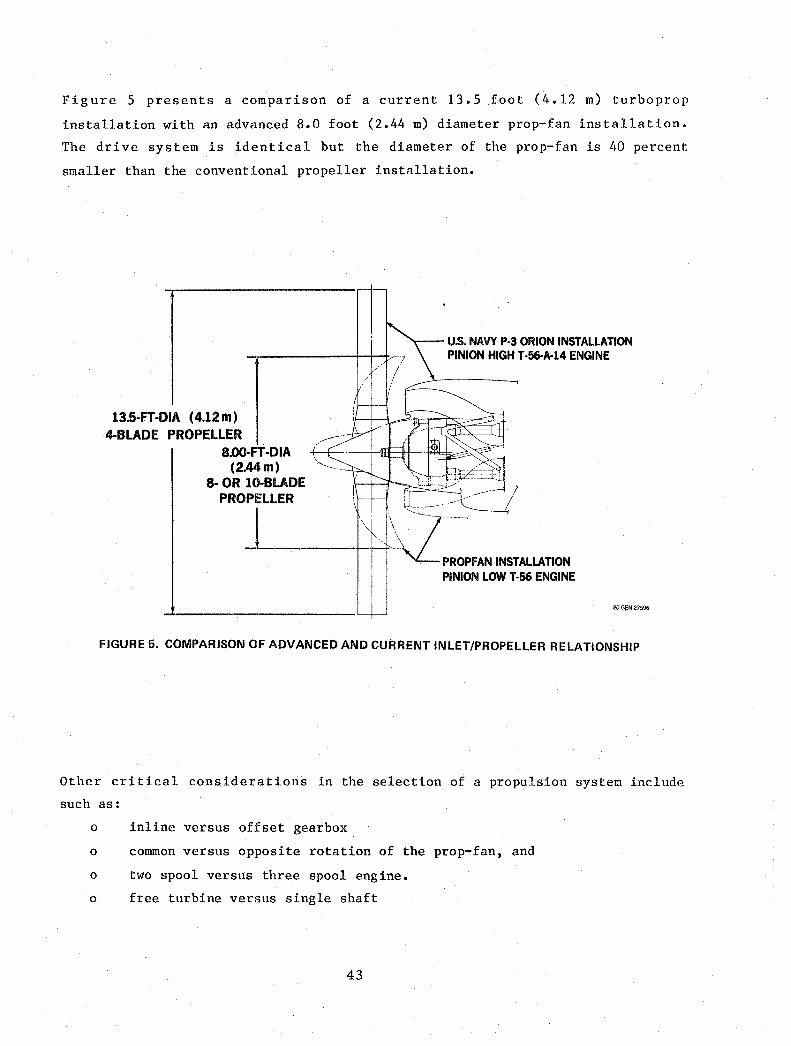
Figure 5 presents a comparison of a current 13.5 foot (4.12 m) turboprop
installation with an advanced 8.0 foot (2.44 m) diameter prop-fan installation.
The drive system is identical but the diameter of the prop-fan is 40 percent
smaller than the conventional propeller installation.
13.5·FT ·DIA (4.12 m) 4·BLADE PROPELLER
8.oo·Fi ·DIA (2.44m)
8· OR lO·BLADE ',--"
u.s. NAVY P-3 ORION INSTALLATION PINION HIGH T-56-A-14 ENGINE
PROPELLER ,r
--L _____ +-\}-j-' -1" i"-\~=FAN INSTAlLATION
PINION LOW T-56 ENGINE
SO·GEN-27596
FIGURE 5. COMPARISON OF ADVANCED AND CURRENT INLET/PROPELLER RELATIONSHIP
Other critical considerations in the selection of a propulsion system include
such as:
o inline versus offset gearbox
o common versus opposite rotation of the prop-fan, and
o two spool versus three spool engine.
o free turbine versus single shaft
43
The gearbox configuration and location not only affects the prop-fan ground
clearance but is influential on the inlet design. In general, aerodynamically
and acoustically the opposite rotation of wing-mounted prop-fans (both rotating
upward and inboard to the fuselage) is favorable. However, considerations such
as development and tooling costs, spares, noise, performance, and operational
adaptability must be taken into account. Other considerations include an
engine company study of the two-spool versus the three-spool engine, the use of
a free turbine versus a fixed shaft design to meet off-design requirements, and
the effect of these on engine size and weight.
Critical control systems required for satisfactory operation of the prop-fan/
engine propulsion system are
o prop-fan control
o engine control, and
o prop-ran/engine coordinator
Hamil ton Standard recommends the modified 54H60 prop-fan control as expeditious
and satisfactory for the testbed aircraft. Discussions of the necessary
modifications, for the testbed or the existing 54H60 propeller control, is in
subsequent paragraphs. In the case of the engine control for the testbed
aircraft, Allison recommends a modification of the supervisory electronic
control such as is on their T701 engine. The prop-fan/engine coordinator is a
single lever which. permits the pilot to readily control the two-engine testbed
aircraft. This coordinator is considered a requirement for a two-engine
testbed installation; it is still considered neeessary to have individual
engine throttle and propeller pitch levers.
T70l Engine/Modified T56 Gearbox
The T701 engine clearly has the advantage over the other two competing engines
in that it has the highest shaft horsepower capability and is therefore capable
of swinging a larger diameter prop-fan. It also has a free turbine. With the
T70l ~ruise power available, a 9.5 foot (2.90 m) diameter prop-fan gives the
maximum cruise SHP/D2 of 37.5 (301 Kw/m2) at Mcruise of 0.8 at 35,000 feet
(10,668 M).
44
Detroit Diesel Allison (DDA) has proposed that the engine control system, which
can fill the needs for the testbed aircraft, be a modification of the control
system devised for controlling the T701 engine as originally planned for use in
the Heavy Lift Helicopter (HLH) program. (In that HLH program, three T701
engines were connected to drive one helicopter rotor. All of the engines would
have been connected to the rotor drive mechanism but each would be controlled
utilizing torquemeter information so that each engine would take its
proportionate share of the load.) Allison has considered the modifications
necessary for the DC-9 testbed installation and an all electronic system is
proposed.
Since this is a fly-by-wire control system, it is possible to vary the prop-fan
tip speed by changing the prop-fan governor setting and thus controlling the
output torque of the power turbine. This is much easier and less expensive
than changing gearboxes or gears inside of gearboxes such as is required in the
case of the fixed shaft T56 engine. If the prop-fan is sized to have a SHP/D2
= 37.5 (301 Kw/m2) at 100 percent engine RPM at 35,000 feet (10,668 m) and a
Mach number of 0.80, the following maximum power loadings (SHP/D2) are
attainable with the T701 engine as a function of prop-fan tip speed at the same
flight speed and attitude.
Prop-Fan Tip Speed Ft/Sec (m/ sec)
800
700
600
(244)
(213)
(283)
Maximum Cruise Power Loading SHP/D2 Available (Kw/m2)
37.5
34.6
32.4
(301)
(278)
(260)
The question of the use of a T56 gearbox with a T701 engine has been pursued
with Allison. This combination produces a counterclockwise prop-fan rotation
(looking forward) which permits the installation of the powerplant on the left
wing with the tip of the prop-fan approaching the fuselage from below. Thereby
45

the estimated benefits of lowered induced drag and prop-fan noise may be
achieved. Allison indicates that the main power transmission gears of the T56
gearbox will take the larger T70l load while rotating in the opposite
direction, but the accessory drive gear train rotation needs to be reversed by
use of an idler gear so that the accessories which are driven by the gearbox
will have the appropriate rotational direction (oil pressure and scavenge
pumps). This change is required because the direction of rotation of the T701
is opposite to that of the T56.
If the T701 engine is used with the T56 gearbox, it will be necessary to
restrict the engine power output to 5000 shaft horsepower (3,728 Kw) because of
gearbox power limitations. Allison indicates that this power range can be used
during testing on the DC-9 prop-fan testbed aircraft since these high power
levels will not be required for extended time periods. Thus the amount of
overall running time at high power accumulated on the gearbox will not be
great. Allison also estimates that higher values of shaft power input may be
possible if this level of operation is very limited in time and frequency. The
shaft power capability of the T701 engine at altitudes
above approximately 7,000 feet (2134 m) is less than the 5000 shaft horsepower
(3728 Kw) capability of the T56 gearbox. Thus use of the T56 gearbox at
altitude will not be horsepower limited and will not interfere with the
collection of the specified cruise data.
The T701 engine lubricating oil system is integral with the engine, and the oil
is cooled by the fuel that feeds the engine. The T56 gearbox has a separate
lubricating oil system which will require provisions for cooling. The T701
engine has not been in either military or commercial service. The T64 and the
T56 engine have established maintenance centers where these engines can receive
required service; the T701 has none. However, for the testbed prop-fan,
arrangements may possibly be made with Allison for maintenance of the T701.
The T701 provides adequate horsepower for a 9.5 foot (2.90 m) diameter
prop-fan, compared with an 8 foot (2.44 m) diameter prop-fan with the T56 or 7
foot (2.13 m) diameter prop-fan with the T64. The larger diameter prop-fan is
a definite advantage for the testbed program.
46

T64 Engine/Gearbox
The T64 engine has a sea level static takeoff rating of 4,380 shaft horsepower
(SHP) (3266 Kw) and a 35,000 foot (10,668 m) Mach 0.80 rating of 1,920 SHP
(1431 Kw). Using the 35,000 foot (10,668 m) rating along with the maximum
specified SHP/D2 = 37.5 (301 Kw/m2), the maximum prop diameter permissible is
about 7 feet (2.13 m), assuming no losses. Of the three engines under
consideration the T64 has the lowest available SHP and therefore must
necessarily have the smallest diameter prop-fan. On the other hand, its free
turbine design allows the engine to achieve the three prop-fan tip speeds
required by the NASA Testbed Program without the
gearboxes or, alternatively, one gearbox with three
Electric states that the present T64 gearbox may
configuration to provide the prop-fan speeds needed
need for three
sets of gears.
be modified to
by the prop-fan
separate
General
a single
testbed
program, however, it is mandatory that assurance testing of these revised
gearboxes be carried out before the gearbox is used on the prop-fan testbed
program.
The T64 gearbox and engine have a common oil system. This feature can be
preserved for the prop-fan testbed installation. The engine and gearbox oil
are circulated through an airframe mounted and supplied oil-air heat exchanger.
The T64 engine is used on the DeHavilland DHC-S Buffalo, the Shin Meiwa
Industries PS-l ASW flying boat, US-l SAR utility amphibian, and the Aeritalia
G.222 military transport. General Electric would consider bailing an
engine/gearbox combination to NASA for use on the testbed program if the
engine/gearbox were to be subsequently refurbished to the "like-new" condition.
The gearbox can be used in either the pinion high or pinion low configuration.
Because the T64 has a free turbine, it is possible to change the prop-fan tip
speed by changing the free turbine speed without losing a large part of the
available shaft horsepower. For example, at 35,000 feet (10,668 m) at Mach
0.8, ,the fol1o~ing maximum prop-fan power loading (SHP /D2) will be available as
a function of prop-fan tip speed.
47
Prop-Fan Tip Speed Maximum Cruise Power Loading Ft/Sec (m/sec) SHP/n2 Available, (Kw/m2)
7 Ft (2.3 m) Prop-Fan
800 (244) 37.5 (301)
700 (213) 34.4 (276)
600 (183) 31.4 (252)
However, the relatively small diameter prop-fan of 7 feet (2.13 m), which is
compatible with the T64 engine, is quite a disadvantage to this testbed
prop-fan program
T56 Engine/Gearbox
The T56 engine has the advantage of powering in-service U.S. military and
commercial aircraft. It also has a long history of dependability; and its
current usage in these U.S. aircraft shows it to be readily maintainable at a
number of military installations. The gearbox and extension shaft also have a
long history of service with the T56 engine in the C-130, P-3, C-2/E-2 and the
Electra aircraft. The gearbox is used in both the pinion high and pinion low
configurations. The means of maintaining these components are also relatively
widespread in the U.S. and should not present serious problems in this respect
if they are used in the prop-fan testbed program.
Relative to the T701, the low shaft horsepower available from the T56 engine
(2,450 [557 KwJ at 35,000 feet [10,668 m] and Mach 0.80) results in a small
prop-fan (about 8 foot [2.44 m] diameter assuming no losses) to achieve the
specified maximum SHP/n2 = 37.5 (301 Kw/m2 ). Another disdvantage to the use of
the T56 for the prop-fan testbed engine stems from the fact that it is a single
spool engine in which engine power drops off rapidly as engine RPM is
decreased. This is demonstrated in the following table:
48

Percent of Rated Prop-Fan Maximu~ Cruise Power Loa~ing Design Power Loading Engine RPM Ti2 S2eed SHP/D Available, (Kw/m ) SHP /D2. (Kw/m2)
Ft/Sec, (m/sec) 8 Ft. (2.44 m) Diameter Prop-Fan
100 800 (244) 37.5 (301) 37.5 (301)
87.5 700 (213) 22.5 (181) 30.0 (241)
75 600 (183) 17.3 (139) 26.0 (209
Allison has proposed that the testbed DC-9 use either three separate gearboxes
or that one gearbox for the T56 installation be reworked with extra sets of
gears to achieve the three prop-fan tip speeds specified in the NASA Statement
of Work.
It is currently envisioned that the control system for the T56 engine and the
prop-fan on the testbed DC-9 will be the same as that which is in use on the
C-130. Here an air/oil heat exchanger is used to cool the engine and gearbox
lubricating oil. The feasibility of using the existing C-130 overall control
system will receive further study if the T56 engine is one of the two carried
until the end of this prop-fan testbed systems study.
If a T56 engine/gearbox combination is used on the DC-9 testbed aircraft
without change, a clockwise rotation of the prop-fan (looking forward) will
result. For upward rotation of the propeller toward the fuselage, which is
desired to minimize induced drag and cabin noise, installation on the
right-hand wing is required. However, depending on the spanwise location of
the engine, the access to the existing DC-9 fueling/defueling control panel may
have to be modified.
49

LARGE SCALE PROP-FAN/PROP-FAN CONTROLS
As part of Task II, Hamilton Standard suggestions of candidate prop-fan control
schemes for both solid shaft and free turbine engines are discussed herein.
In selecting a gas turbine drive for the large scale prop-fan, various aspects
concerning the operation of the propeller control must be considered.
Consequently, a study is undertaken to evaluate the feasibility of modifying an
existing propeller control so that it can be adapted to a testbed drive system.
The use of an all-new control is also considered. The various prop-fan
configurations are based on a full scale SR-3 prop-fan configuration with 8 and
10 blades in 8 and 10 foot (2.44 and 3.05 m) diameters. At 800 feet per second
(243 m/sec) tip speed, the corresponding prop-fan speeds are 1,910 and 1,528
RPM(200 and 160 radians/sec), respectively.
54H60 Propeller Control and Modifications Required
The prop-fan control selected is used with the 54H60 propeller on the Lockheed
C-130 and P3 aircraft. It readily fits a 60 spline shaft such as is used on
the T56 engine, and it also is the control with the highest pumping capacity.
In addition to being compatible with the T56, a solid shaft engine, it is also
compatible with the T701, a free turbine engine. However, with this T701
installation, additional modification to the 54H60 control will be required in
order to obtain speed variability. The 54H60 control presently operates at
1020 RPM (107 radians/sec) and is designed for pump flows of about 60 quarts
per minute(.946 l/sec). A whirl test was performed on a modified 54H60 control
and propeller hub to determine the feasibility of operating at 1,800 RPM (188
radians/sec)(i.e., 80 percent above the design speed) and the capability of
withstanding the loads imposed at this speed. It was concluded from those
tests that the 54H60 control, with minor modifications, can be operated at
1,800 RPM (188 radians/sec) if adequate cooling is provided to the transfer
bearing. The minor modifications include removal of items such as flyweights,
low pitch stop levers, the main pump drive gear, speed bias and linkage;
blockage of the standby valve, increase in the transfer bearing clearance, and
insertion of a new beta feedback cam.
50
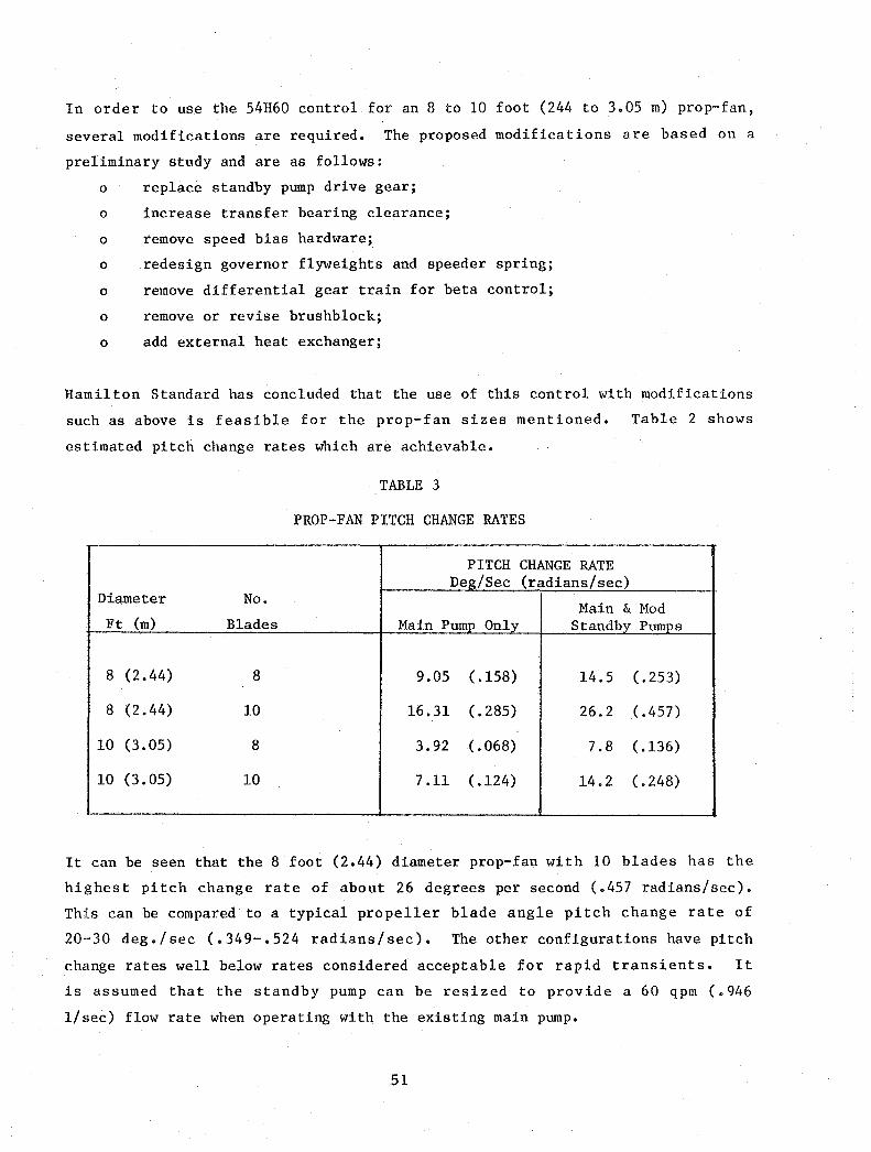
In order to use the 54H60 control for an 8 to 10 foot (244 to 3.05 m) prop-fan,
several modifications are required. The proposed modifications are based on a
preliminary study and are as follows:
o replace standby pump drive gear;
o increase transfer bearing clearance;
o remove speed bias hardware;
o redesign governor flyweights and speeder spring;
o remove differential gear train for beta control;
o remove or revise brushblock;
o add external heat exchanger;
Halnilton Standard has concluded that the use of this control with modifications
such as above is feasible for the prop-fan sizes mentioned. Table 2 shows
estimated pitch change rates which are achievable.
TABLE 3
PROP-FAN PITCH CHANGE RATES
PITCH CHANGE RATE Deg/Sec (radians/sec)
Diameter No. Main & Mod
Ft (m) Blades Main Pump Only Standby Pumps
8 (2.44) 8 9.05 (.158) 14.5 (.253)
8 (2.44) 10 16.31 (.285) 26.2 (.457)
10 (3.05) 8 3.92 (.068) 7.8 ( .136)
10 (3.05) 10 7.11 ( .124) 14.2 (.248)
It can be seen that the 8 foot (2.44) diameter prop-fan with 10 blades has the
highest pitch change rate of about 26 degrees per second (.457 radians/sec).
This can be compared to a typical propeller blade angle pitch change rate of
20--30 deg./sec (.349-.524 radians/sec). The other configurations have pitch
change rates well below rates considered acceptable for rapid transients. It
is assumed that the standby pump can be resized to provide a 60 qpm (.946
l/sec) flow rate when operating with the existing main pump.
51

The existing standby pump cannot be utilized because the pump flows would
approach 90 qpm (1.350 l/sec) and the resulting line velocities would be
excessi ve, thus generating high friction and excessive heat. This also leads
to foaming and cavitation. It is recommended that the tranfer bearing
clearance be increased for cooling, and that an external heat exchanger be
added. For the 60 qpm (.946 l/sec) flow rate, it is recommended that a ~P of
approximately 1,000 psi (70.32 kg/cm2) across the piston be used instead of the
600-700 psi (42.2 - 49.2 kg/cm2 ) which is typical on the existing control.
This control is capable of operating at 1,000 psi (7032 kg/cm2) since its high
pressure relief setting is about 1,250 psi (87.90 kg/cm2).
New Propeller Control
Since it has been determined that the 54H60 control with modifications is
feasible for a prop-fan research vehicle in the size studied, the discussion of
new controls shall be limited. First, consider why a new control might be
desired. The reasons which seem plausible are:
o pitch change rates must be higher for transient tests, or
o further, more detailed, study of the 54H60 control reveals an
inadequacy not currently known.
Of course, a new control can be built for the testbed, but it will look
very much like a 54H60 control since it must be compatible with the T56
gearbox and its 60 spline shaft. Allison advises that there is no access
through the gearbox shaft centerline or planet carrier. Therefore, a
shaft mount transfer bearing is required just as presently used. A new
control will require an increased flow and/or pressure system to yield
higher pitch change rates. Pitch control systems such as used on the
Q-Fan Demonstrator, or QCSEE, required access through the gearbox and are
not applicable here. An alternate to a new shaft mounted control is a
rotating pumping system where the control is mounted out on the rotating
hardware. This arrangement has been previously accomplished
experimentally, but does represent an all new control development program
which is considered unnecessary and offers no advantage.
S2

Free Turbine vs. Single Shaft Engine Controls
The last area investigated deals with control functions and the application of
the control to a free turbine (dual shaft) versus single shaft engine. As
mentioned earlier, the 54H60 control is compatible with either type of engine;
it is already coupled with the T56 engine in the P-3 and C-130 aircraft. A
single shaft engine requires a negative torque sensing (NTS) system which
prevents gearbox decoupling during airs tart but accomplishes decoupling during
excessive windmilling RPM to prevent high drag. This feature may not be
necessary for the prop-fan hardware if the gearbox decoupler is eliminated and
an alternate means of protection against excessive drag is instituted. This
latter decision may be influenced by the aircraft type being considered and the
impact of high drags. The NTS is the only prop-fan control hardware difference
between the two engine types.
Pitchlock
It is recommended that the prop-fan rotating hardware incorporate a pitchlock
device of some type which will prevent overspeeds incase of inadvertent blade
angle decreases. Use of the 54H60 type pitchlock is not feasible in the
prop-fan type actuator, nor is the prop-fan pitchlock concept compatible with
the 54H60 type control. The easiest way to handle the problem is with a ground
adjustable stop which is set before each test to a blade angle just below the
anticipated test angle. This type of stop would require numerous landings and
resettings. So while it is easily accomplished, it is not convenient for
testing. An alternate to this is an electrically operated in-flight adjustable
stop. Such a stop is certainly feasible but requires careful use so that the
stop location is always known; otherwise its protection is useless. The last
and most sophisticated method of achieving pitchlock protection is an in-place
type lock similar to the concept used on the commuter propellers and which is
planned for the production prop-fan. This concept requires incorporation of a
beta control loop in the prop-fan itself. In order to provide a rotary signal
to operate the pitchlock, a hydraulic motor circuit is required to introduce
the requested blade angle. A modification to the 54H60 control is required to
provide a pressure to the hydraulic motor located in the hub.
53
Normal Governing, Feathering and Reversing
Other operations performed by the prop-fan control include normal governing,
feathering and reversing. Normal governing can be handled easily by a modified
or a new control for either engine type. The type of engine has no bearing.
Feathering will probably be slow (low pitch change rate); and feathering out of
an overspeed where higher pitch change loads exist may not be possible with a
modified 54H60 control. However, with adequate overspeed protection, this may
be of little consequence. Unfeathering should not be a problem with the
modified control. Use of an auxiliary electrically operated hydraulic pump
already on the 54H60 control will be used. Reverse operation with the 54H60
control is in a beta mode where the pilot controls the blade angle and the
engine coordinator maintains a scheduled fuel flow to keep the RPM constant.
This control does not govern or control RPM in reverse as it does in normal
flight operations. The reversing scheme for the prop-fan will probably be
fixed blade angle reversing. While this may impact solid shaft engine
operation, it is not a problem for the control. The blade angle will simply be
directed to decrease pitch until a stop is reached. For the multi-bladed
prop-fan, a beta control system has not been designed. Such a system can
probably be designed and developed if necessary; however, this system does not
seem to be warranted for this propulsion testbed program.
While a modified 54H60 control, or even a new control, appears to be able to
handle the desired propfan functions discussed above, there are some points
concerning engine type to discuss further. Maintaining constant RPM during
operations such as reverse will be difficult with a fixed blade angle. Speed
control will have to be maintained by the T56 engine overspeed governor or
controller; this requires further study. There is no problem of this type on a
free turbine engine. Another area of concern on a solid shaft engine is with
the use of a fixed pitchlock stop. For example, assume the pitchlock stop is
set just below the test blade angle and then power is retarded. The blade
angle will stop at the setting and the RPM will then want to decrease with
further power reduction.
Assuming the test is being accomplished at 0.8 Mach and the desired test blade
angle is 57 degrees (.995 radians), a 60 percent decrease in shaft horsepower
54

requires a 4 degree (.070 radians) decrease in blade angle to maintain 100
percent RPM. If a stop is set just a few degrees below the desired test angle,
then a power retardation may result in a RPM dropoff. Again, this requires
further study. Lastly, the airstart procedure may be more difficult on a solid
shaft engine if the pitchlock stop is set such that 100 percent speed cannot be
achieved at flight idle power setting. Further coordination with the engine
manufacturer is required.
Prop-Fan Control Capability
In summary, a modified propeller control is feasible for a prop-fan of 8-10
feet (2.44-3.05 m) diameter. For each size, ten blade configurations have
higher pitch change rates (Table 3). In three of the four configurations
considered, transient capability is quite poor. In only one case is it
reasonable. All propeller control features can be provided with a modified
control. There are potential problems with either a modified or new control
associated with using a single shaft engine. However, none of these problems
are insurmountable.
Prop-Fan/Nacelle Compatibility
Hamilton Standard will coordinate with Douglas in evaluating candidate drive
systems for compatibility and suitability in meeting technical objectives. The
nacelle size and shape are critical aerodynamically, since it has been
determined analytically as well as in prior Hamilton Standard model design work
that nacelle shape has a significant influence on inboard blade flow
characteristics. In order to maintain adequate choke margins in the root area,
the question of nacelle size and contour for a prop-fan rotor size of a
specific engine is also important.
Utilization of an 8 foot (2.44 m) diameter prop-fan on the T56 engine and a 10
foot (3.05 m) diameter prop-fan on the T701 engine indicates that excessive
blockage exists with the existing P-3 nacelle. Modification of the P-3 nacelle
for use with the T56 engine requires either engine inlet resizing or a smaller
overall nacelle diameter. Utilization of a new nacelle on the T701 engine
results in blockage characteristics compatible with the prop-fan concept.
55

Figures 6 and 7 indicate that the velocity ratio vIVo, is low and the
efficiency, n, is high for the P-3 application when compared to the SR-3
prop-fan configuration. The results for the P-3 were based on measurements in
a model test at MN = .75, and extrapolated to MN = 0.8. The SR-3 results are
theoretical, and utilize a nacelle exhibiting a diameter which is 35 percent of
the diameter of the prop-fan, with no inlet.
86~------~--------~~----~------~--------~ ~N=O.8. 35.000 FT (10.668 m) TIP SPEED =000 FPS
(244m/sec) I
DESIGN POINT
82~------4--------+------~--~~r-+-------~
NET EFFICIENCY (PERCENT)
78~-------r------~r-------~-------4------~
0 10 20 SHP/02
30 40 50
I I I 100 200
kW/m2 300 400 82.GEN.23676
FIGURE 6. PERFORMANCE COMPARISON BETWEEN P3A VERTICAL RAKE AND SR·3 PROP·FAN WITH 35-PERCENT BODY
VIVo
1.1
1.0
0.9
0.8
0.7
0.6 0.2
M1=0.8 I
BLADE DIA = 8 FT l.------~ ------sR.3 WITH 35 PERCENT
NACELLE NO INLET
...",. --~
/ ----./ ...---L-;;WITH P3A NACELLE - (VERTICAL RAKE)_ ----
0.3 0.4 0.5 0.6
r/R
0.7 0.8 0.9 1.0 82·GEN·23670
FIGURE 7. BLOCKAGE COMPARISON BETWEEN P&A VERTICAL RAKE AND SR·3 PROP.FAN WITH 35·PERCENT
56

COCKPIT CONTROLS AND INSTRUMENTATION
A review of the necessary constraints on available space and cockpit procedure
has been made to assess the suitability of the DC-9 as a platform for the
prop-fan testbed. This examination shows that the most suitable cockpit
arrangement is to mount the prop-fan drive system controls on the cockpit
center console, in the vicinity of the existing controls for the Pratt and
Whitney JT8D, the basic propulsors for the DC-9. This arrangement will permi t
control of the prop-fan drive system by either the pilot or the co-pilot. In
the event of an emergency one flight crew member can assume control of the DC-9
while the other member controls the prop-fan drive system. There is adequate
space for these controls near the center console. The modifications to the
aircraft are not extensive and will not compromise the basic safety of the DC-9
testbed aircraft.
The cockpit instrumentation will be held to a minimum yet will be adequate to
allow for starting, stopping, accelerating, decelerating and otherwise
controlling the prop-fan drive system. It will also allow for monitoring and
setting the key prop-fan drive system operating parameters. This
instrumentation will be installed closer to the co-pilot's station but will be
clearly readable by the pilot. These controll instrumentation arrangements are
simplified on the DC-9 because there is such good cross-cockpit visibility and
proximity which isa product of the basic two-man cockpit design of the
aircraft. The cockpit instrumentation which has been preliminarily identified
are concerned with the following:
o gas generator speed
o power turbine speed (or prop-fan RPM)
o power turbine inlet temperature
o engine fuel flow rate
o gearbox output torque
o gearbox and engine oil pressure and temperature.
57

DRIVE SYSTEM SUMMARY
The foregoing discussion of the characteristics of candidate drive systems for
the prop-fan testbed aircraft is summarized in the following figures:
ITEM ENGINE
T701-AD-700 T56-A-15 T64-P4D
GEARBOX MODIFIED T 56 MODIFIED T 56 MODIFIED T644
AVAILABLE SHAFT HORSEPOWER (kW)
SEA LEVEL 8050 (6002) 4591 (3423) 4380 (3266) 35,000 FT (10,668 m) 3625 (2703) 2450 (1826) 1920 (1431)
GEARBOX POWER LIMIT - HP (kW) 5000 CO NT (3728) 5000 CONT (4728) 3400 CONT (2535) 6000 SHORT (4474) 6000 SHORT (4474)
TIME TIME
POWER-TURBINE TYPE FREE FIXED SHAFT FREE
WEIGHT WITH GEARBOX - LB (kg) 1810 (821) 1843 (836) 1188 (539)
. LENGTH - IN. (em) 124.55 (316.36) 145.98 (370.78) 110.20 (279.91)
WIDTH - IN. (em) 30.55 (77_6) 27.25 (69.2) 29.49 (74.9)
HEIGHT - IN. (em) 46.12 (117.2) 41.38 (105.1) 45.92 (116.6)
AVAILABILITY 51N STORAGE IN PRODUCTION IN PRODUCTION BAIL FROM ARMY
FIGURE 8. CANDIDATE PROPelLER DRIVE SYSTEMS 80·GEN-27549B
SHP/D2, (kW/m2)
TIP SPEED- T701 T56 T64 FT PER SECOND RPM MIN 10·FT (3.05 m) 8·FT (2.43 m) 7-FT (2.13 m)
(m/SEC) (PERCENT) REQ PROP PROP PROP
800 (244) 100 37.5 (301) 37.5 (301) 37.5 (301) 37.5 (301)
700 (213) 87.5 30 (241) 34.6 (278) 22.5 (181) 34.4 (276)
600 (183) 75 26 (209) 32.4 (260) 17.3 (139) 31.4 (252)
60·GEN-27560A
FIGURE 9. ESTIMATED CAPABILITY WITH FIXED RATIO GEARBOX (PROPelLER SIZED AT 800 FEET PER SECOND (344 m/SEC) AT CRUISE)
58

ENGINE
ITEM T701-AD-700 T56-A-15 T64-P4D
MAXIMUM CRUISE SIZED PROPELLER DIAMETER - FT, (m) 9.5 (2.90) 8.1 (2.57) 7.2 (2.19)
NACELLE BLOCKAGE* ACCEPTABLE HIGH UNACCEPT ABLE 0.34 0.40 0.43
GEAR REDUCTION RATIO 7.5:1 7.2:1 6.2:1 8:1 9:1
. * HAMILTON STANDARD CRITERIA (0.35)
(NACELLE BLOCKAGE IS A CRITERIA ESTABLISHED BY HAMILTON STANDARD AND IS THE RATIO OF THE NACALLE EQUIVALENT DIAMETER TO THE PROp·FAN DIAMETER.)
BO·GEN·27559B
FIGURE 10. PROPELLER DRIVE SYSTEM COMPARISON SUMMARY
As can be seen from Figures 8,9 and 10, the results of the evaluation of the
three available prop-fan drive systems clearly indicates that the Allison T701
with the T56 modified gearbox is the best choice for the testbed aircraft. The
primary influencing factors in this decision are that
o the T701 engine develops enough power at cruise to drive a 9.5 foot
(2.90 m) diameter prop-fan at design speed and power loading; and
o the free turbine design provides the engine with the flexibility
required to accommodate tip speed and power loading variations
over a wide operating range without entailing gear changes.
Also, the Allison T701 engine has a commercial counterpart (570) which may be
used as a back-up engine in case the T701 becomes unavailable for use on the
testbed aircraft. This 570 commercial engine differs from the T701 by only a
minor weight increase (15 percent) due to material substitution of some steel
for titanium in the engine case.
59
The verification of the structural and performance integrity of the installed
prop-fan is vital to the prop-fan aircraft testbed program. As stated
previously, the aim of the prop-fan testbed program is to provide verification
in an expeditious manner by utilizing an appropriate existing engine/gearbox
hardware and an existing large scale prop-fan design. It is necessary that the
diameter of the prop-fan used for the testbed be as nearly full-scale as
possible so that scaling does not become a problem. Thus the T701 with its
capability to swing a 9.5 foot (2.90 m) diameter prop-fan is particularly
desirable.
The second choice for the drive system is the T56 engine and gearbox. This
drive system is sufficient to power an 8 foot (2.74 m) diameter prop-fan, but
its single shaft design requires physical changes of gears in order to meet the
minimum required combination of tip speeds and power loadings. Additional
hardware, flight test time, and cost are likely to be incurred with this drive
system.
The T64 is the least suitable of the three engines for the testbed program
because it can only accommodate a 7 foot (2.13 m) diameter prop-fan.
Considering that the testbed program is primarily aimed at investigating
prop-fan structural integrity for a representative blade construction, it is
desirable that the prop-fan be substantially larger than 7 foot (2.13 m)
diameter.
The recommended prop-fan drive system, including the selection rationale, is
summarized as follows:
SELECTION
Free Turbine
T70l
Modified T56 Gearbox
REASON
Precludes need for mUltiple gear ratios and
enables independent setting of RPM and pitch
Enables largest diameter propeller tests
Low cost
60


TASK III
CANDIDATE TESTBED AIRCRAFT
INITIAL SURVEY OF POSSIBLE CANDIDATES
In work prior to the initiation of the study, Douglas Advanced Engineering had
surveyed several candidate aircraft which might be suitable as a prop-fan
testbed vehicle. The rationale and requirements for selection of a suitable
aircraft are as follows:
o testbed must be capable of Mcruise of approximately 0.8 at 30,000
feet (9,144 m) or greater;
o test engine/prop-fan is not part of the primary propulsion system;
o testbed configuration locates the prop-fan in the proper flow
environment compatible with an actual prop-fan aircraft
arrangement;
o prop-fan testbed configuration must be representative of the airframe
interaction to be expected in an actual aircraft design;
o testbed must be capable of providing verification of existing
wind tunnel results and analytical prediction methods;
o minimum modification to the basic aircraft for the testbed is
desired, therefore, the cost of the program is minimized;
o basic design data for the testbed aircraft (such as structure,
aerodynamic, and fabrication) must be readily available to the
Contractor;
o it is desirable that the testbed aircraft be directly oriented toward
a commercial aircraft configuration;
o testbed should be compatible with a first flight of approximately
1985;
o configuration should be compatible with an approximate 10 foot
(3.05 m) diameter prop-fan for the testbed; the large diameter
prop-fan is a definite plus and is a desirable feature from Hamilton
Standard's point of view of having the testbed prop-fan sufficiently
large that extrapolation of results to the full scale case is
reasonable and valid.
61

During the pre-study, survey the aircraft other than those of Douglas which
were reviewed on a preliminary basis as potential testbed candidates included
Lockheed Electra and C-141, Boeing B-52, 707, 727, 737, and C-14. These
aircraft were judged inappropriate on such bases as:
o Incapable of sustained Mcruise of approximately O.S at
30,000 feet (9,144 m);
o ground clearance problems;
o inability to provide proper flow environmental conditions
and thus to provide a basis for verification of existing
analytical results.
Those Douglas aircraft surveyed as a possible testbed were the DC-S, C-15,
A-3D, and DC-9. Possible DC-S arrangements, utilizing the existing structural
hard points, incurred low prop-fan ground clearances. Also, the DC-S is a more
expensive aircraft for a testbed than the DC-9.
The C-15 does not have a passenger interior, is not a Mach Number = O. S cruise
aircraft, and does not provide a particularly good location of the prop-fan
relative to the wing. The A-3D aircraft is capable of the M = 0.8 cruise and
adequate ground clearance for a prop-fan installation of at least 13 feet
(3.96 m) diameter; however, the A-3D aircraft is a military design and
consequently the fuselage is not characteristic of a passenger fuselage from
the pressurization aspects, the interior acoustic treatment, or from the
geometric cross section.
On the basis of the above mentioned criteria, the DC-9 with a wing-mounted
prop-fan installation is judged a most appropriate testbed aircraft.
62
ADVANTAGES OF DC-9 AIRCRAFT AS SELECTED PROP-FAN TESTBED
The DC-9 aircraft, either a -10 or a -30 version, is a particularly sound
selection for the NASA prop-fan testbed research aircraft for the following
reasons:
o The DC-9 is an available aircraft which is low cost from both the
acquisition and operational points of view.
o The DC-9 is a Douglas aircraft, and consequently full knowledge of the
aircraft detail design, flight characteristics, and modification
know-how are immediately available to Douglas and to the NASA advanced
turboprop project.
o The aircraft is a commercial vehicle which enjoys an enviable
reputation among the airline users.
o Either the -10 or -30 aircraft may be made available for the testbed;
however, the -10 is more cost-effective from the initial investment
point of view. Either aircraft is efficient costwise as a testbed.
The immediate availability of the specific aircraft may be dependent
on the timing of the program requirement for acquisition of an
airplane.
o No modification of the aircraft is required except for the wing
installation of the prop-fan/engine/nacelle. The wing is not expected
to require beef-up; with the possible exception of the low speed/low
altitude one-engine-out condition, the existing empennage is adequate
to meet the aircraft stability and control requirements for an
asymmetical testbed arrangement with one prop-fan nacelle mounted on
the wing.
o The prop-fan may be properly placed on the wing to acquire the
practical prop-fan interactions which may be encountered in an actual
design - such as nacelle/wing, prop-fan/wing, and prop-fan/fuselage
interferences.
63
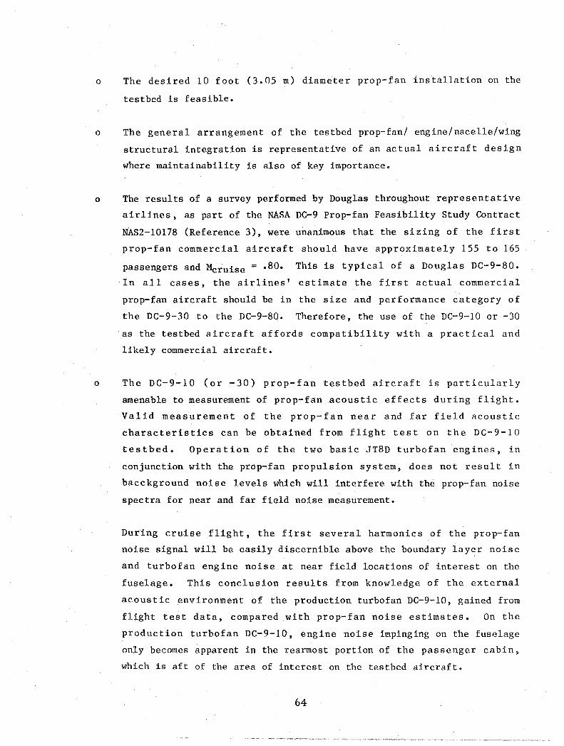
o The desired 10 foot (3.05 m) diameter prop-fan installation on the
testbed is feasible.
o The general arrangement of the testbed prop-fan/ engine/nacelle/wing
structural integration is representative of an actual aircraft design
where maintainability is also of key importance.
o The results of a survey performed by Douglas throughout representative
airlines, as part of the NASA DC-9 Prop-fan Feasibility Study Contract
NAs2-1017S (Reference 3), were unanimous that the sizing of the first
prop-fan commercial aircraft should have approximately ISS to 16S
passengers and Mcruise = .SO. This is typical of a Douglas DC-9-80.
In all cases, the airlines' estimate the first actual commercial
prop-fan aircraft should be in the size and performance category of
the DC-9-30 to the DC-9-S0. Therefore, the use of the DC-9-10 or -30
as the testbed aircraft affords compatibility with a practical and
likely commercial aircraft.
o The DC-9-10 (or -30) prop-fan testbed aircraft is particularly
amenable to measurement of prop-fan acoustic effects during flight.
Valid measurement of the prop-fan near and far field acoustic
characteristics can be obtained from flight test on the DC-9-10
testbed. Operation of the two basic JTSD turbofan engines, in
conjunction with the prop-fan propulsion system, does not result in
bacckground noise levels which will interfere with the prop-fan noise
spectra for near and far field noise measurement.
During cruise flight, the first several harmonics of the prop-fan
noise signal will be easily discernible above the boundary layer noise
and turbofan engine noise at near field locations of interest on the
fuselage. This conclusion results from knowledge of the external
acoustic environment of the production turbofan DC-9-10, gained from
flight test data, compared with prop-fan noise estimates. On the
production turbofan DC-9-10, engine noise impinging on the fuselage
only becomes apparent in the rearmost portion of the passenger cabin,
which is aft of the area of interest on the testbed aircraft.
64

Prop-fan far field noise can be measured using the testbed aircraft
during static and taxi testing with no problems involving
contamination of the prop-fan noise signal by extraneous noise
sources, such as turbofan engine noise. If far field noise
measurements during flyovers become a possibility, the problem of
signal contamination can be avoided by limiting the turbofan thrust
(this may suggest the measurements be made while the aircraft is in a
slight descent).
DC-9 TESTBED CONFIGURATIONS
Three views of the prop-fan testbed DC-9-10 aircraft are presented in Figures
11 and 12 for the Allison turboshaft T70l and the T56 single engine
installations. Three-views of the two prop-fan nacelle installations on the
DC-9-10 and DC-9-30 are shown in Figures 13 and 14. The principle differences
between the DC-9-30 and the DC-9-10 from the standpoint of a prop-fan testbed
are as noted:
o The DC-9-30 aircraft has leading edge slats which the -10 does not.
In the case of the -30, these leading edge slats, or portions thereof,
must be deactivated due to the prop-fan nacelle installation.
o In order to prevent excessively high sideslip angles, the rudder
deflection of the DC-9-30 has been limited to 17.2 degrees (.300
radians) at flap deflections of 15 degrees (.262 radians) and above
and to 13.2 degrees (.230 radians) for flap deflections below 15
degrees (.262 radians). The rudder deflection on the DC-9-10 is not
limited but utilizes the full 30 degree (.524 radians) deflection;
therefore, it is probable that the -10 testbed may be safely operated
at lower speeds at low altitudes than the -30 testbed.
The existing empennage of the DC-9-10 is capable of providing adequate
stability and control for the asymmetric prop-fan testbed configuration;
however, a small restriction on the low speed/low altitude envelope may need to
be imposed in deference to the one-engine-out condition.
65

PROp·FAN PROPULSION SYSTEM (1) ALLISON T701 TURBOSHAFT ENGINE 1 HAMILTON STANDARD
- la-FOOT 3.05 m DIAMETER PROp·FAN
NOTE: WING INSTALLATION COMPATIBLE WITH ENGINE ROTATION SO THAT PROP·FAN ROTATES Up·INBOARD TO THE FUSELAGE
BASIC DC·9 TURBOFAN ENGINES REMAIN ON TESTBED AIRCRAFT AND SUPPLY POWER AS REOUIRED
... ~
104 FT 4.8 IN. (31.7 m) ---A~~~r
43 FT 8 IN. \13.3 m) --i t---------~ .. 92FTO.lIN.(27.9m)
80-GEN·21431A
FIGURE 11. DC-9·10 PROP·FAN TESTBED -ONE ALLISON T701 ENGINE
PROP·FAN PROPULSION SYSTEM 1 ALLISON T56 TURBOSHAFT ENGINE 1 HAMILTON STANDARD
- 8· 00 2.44 DIAMETER PROp·FAN
NOTE: WING INSTALLATION COMPATIBLE WITH ENGINE ROTATION SO THAT PROP·FAN ROTATES UP·INBOARD TO THE FUSELAGE
1--89 FT42.'N 121.2 m)~ I L C .. , UZ'::::::='::;:::=:r====, I r=~'i~"i'
3·DEG DIHEDRAL -t. :r--~~~~~--104 FT 4.8 IN. (31.7 m) ------"'i 16 FT 4.2 IN. (4.9 m)
BASIC DC·9 TURBOFAN ENGINES REMAIN ON TESTBED AIRCRAFT AND SUPPLY POWER AS REOUIRED
80 GEN 27413A
FIGURE 12. DC-9·10 PROP.FAN TESTBED - ONE ALLISON T56 ENGINE
66
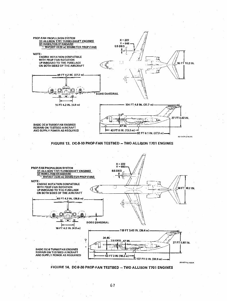
PROP· FAN PROPULSION SYSTEM (2) ALLISON T701 TURBO-SHAFT ENGINES (2) HAM I L TON STANDARD ~ 10·FOOT (3.05 m) DIAMETER PROP·FANS
NOTE: ENGINE ROTATION COMPATIBLE WITH PROP· FAN ROTATION UP·INBOARD TO THE FUSELAGE ON BOTH SIDES OF THE AIRCRAFT
r 1"----- 104 FT 4.S IN. (31.7 m)----:::~~~T
7
I BASIC DC·9 TURBOFAN ENGINES REMAIN ON TESTBED AIRCRAFT AND SUPPL Y POWER AS REQUIRED
¢ ;47 IN. --,..-------;----1. I- 43 FT SIN. (13.2 m)-l
1---------92 FT 0.1 IN. (27.9 m)
FIGURE 13. DC·9·10 PROP·FAN TESTBED - TWO ALLISON T70l ENGINES
PROP·FAN PROPULSION SYSTEM (2) ALLISON T701 TURBOSHAFT ENGINES (2) HAMILTON STANDARD ~ 10·FOOT (3.05 m) DIAMETER PROP·FANS
NOTE: ENGINE ROTATION COMPATIBLE WITH PROP·FAN ROTATION UP·INBOARD TO THE FUSELAGE ON BOTH SIDES OF THE AIRCRAFT
r-=~ m2lN: '~Sm'
,;j~; J;,,) , : --j: -L- t- 3·DEG DIHEDRAL
BO-GEN-27412A
16 FT 4.2 IN. (4.9 m) /"0--------119 FT 3.43 IN. (36.4 m)--_-::~~~~
BASIC DC·9 TURBOFAN ENGINES REMAIN ON TESTBED AIRCRAFT AND SUPPLY POWER AS REQUIRED
34.45 .___--t--2•5 DEG - 47 IN. -------r~~---L
OOOOOO~~O~
I--- 53 FT 2 IN (16.2 m)~ t-----------~107 FT 0 IN. (32.6 m)
FIGURE 14. DC-9-30 PROP·FAN TESTBED - TWO ALLISON T701 ENGINES
67
80-GEN-2~420A

Stability and Control Characteristics
Figure 15 presents the flight envelope showing stability and control for the
DC-9-l0 prop-fan testbed.
-e § ... ..... au 0 :::)
t:: t-..J <
(20)
(ll6)
(ll2)
(8)
(4)
60r---------------------------------------~
50
E §40 ... ..... 30 au o :::) t-~ 20 <
10
DC·9·10
V MIN 80.000 LB (36.28 kg) (NO FLAPS)
FLIGHT REGIME
O~ __ ~~~~~~~~~ __ ~ ____ ~ __ ~ __ ~ 50 100 150 200 250 300 350
EQUIVALENT AIRSPEED (KNOTS)
(l00) (200) I I I I I
(300) (400) (500) (600) (700) EQUIVALENT AIRSPEED (km/HR)
450
I I (800) (900)
8O·GEN·27421B
FIGURE 15. PROP·FAN TESTBED FLIGHT ENVELOPE FOR STABILITY AND CONTROL
The high-speed limits are set at MFC/VFC and are the same as for the basic
DC-9-l0. Minimum 19 flight speed at 80,000 pounds (36,281 kg) gross weight
with flaps up is shown as a lower limit. The gray area illustrates a region
where asymmetric thrust due to operation of the turboprop will require
increasingly large sideslip, bank angle, and control deflections as speed
decreases. This region must be investigated in flight test to demonstrate
controllability. The desired M = 0.5 and 0.8 flight conditions are indicated
in the foregoing figure. The flight envelope of the DC-9-30 is nearly the same
as for the DC-lO-lO with only small differences in the high-speed limits. The
low speed limits and flight test requirements remain the same.
68
Because of the destabilizing effect of the prop-fan system on static
longitudinal stability, the aft center-of-gravity limit must be moved forward
3 percent MAC (mean aerodynamic chord), from the basic DC-9, for each prop-fan
system used. The resulting aft center-of-gravity limits for the Series 10 and
30 DC-9 with one and two prop-fan systems will be as shown below.
DC-9 Series No. of Prop-fans Aft C.G. Limit
%MAC
10 1 36
10 2 33
30 1 31.7
30 2 28.7
For the single prop-fan configuration the lateral control performance in the
low-speed flight conditions will be degraded to some extent by virtue of the
loss of flap area under the prop-fan nacelle. This flap asy~netry requires the
use of 15 percent of available lateral control authority to balance when
20-degree (.349 radians) flaps are used and 20 percent of available authority
when 50 degree (.873 radians) flaps are used. No lateral control is required
to offset the prop-fan system weight in the single-engine configuration because
ballast is added in the opposite wing to balance the airplane laterally. Thus
the nuisance roll response to pitch maneuvers with laterally unbalanced
ai rplanes is avoided. The added rolling moments of inertia created by the
prop-fan system and ballast weights will cause a reduction in roll control
response or roll acceleration by as much as 33 percent. Another 17 percent
reduction in roll response will occur as a result of the lost spoiler area.
These losses are significant in the low-speed condition and may require
overspeeds of approximately 20 percent if lateral control responsiveness is to
be retained.
Although the two-engine configuration does not have the asymmetry problems of
the single-engine configuration, it too has the degraded roll performance
resulting from increased rolling inertia and reduced spoiler area. A similar
overs peed consideration is recommended for this configuration.
69

Stall speeds and resulting reference speeds are expected to increase with the
unpowered prop-fans. Confirmation of these speeds must be obtained from
wind-tunnel test data and established for the flight evaluation program. These
new highE!r reference speeds are likely to accommodate, to some extent, the
overspeeds suggested for roll performance.
A stick pusher system is designed and currently available for the DC-9. This
system could be employed on the testbed airplane, if necessary, to avoid stalls
by programming the pusher trigger point to whatever angle of attack schedule is
appropriate.
DC-9 Prop-fan Performance Estimates
Cruise Capability
The limiting operating points assumed for the performance spectrum are those
shown in Figure 16 and are representative of the boundaries of the DC-9
prop-fan aircraft flight envelope.
(12) 40
- -30 e t: § (8) § .... .... - - 20 LI.I LI.I 0 0 ;:) ;:) t- t-~ (4) ~ cC cC 10
I (0) 0.1
~, .. ,..' ,,' " ~~/ ." 0'/
.~/ ..4tJ',.,:
(b ..... Jp,lf).'/ \.:~
~/
~~I .1/
~I ~:'.
I . I
I
;1 I I ,
0.2 0.3
/
I I
I I
0.4
/ I
/" /
I
0.5
Mo
,. 0 ,. ,. / ""TESTBED
/ FLIGHT /' / ENVELOPE-
I
/ V
0.6 0.7 0.8 I
0.9
80·GEN·27500A
FIGURE 16. DC-9 AIRCRAFT OPERATING POINTS ASSUMED IN PERFORMANCE SPECTRUM
70
In order to determine the capability of the DC-9-10 prop-fan aircraft to
provide adequate cruise time as a prop-fan testbed, estimates of cruise times
which will be available to test prop-fan engine combinations are determined for
the assumed six Mach number/altitude test conditions. The variables considered
are
2 airplanes: DC-9-10 or DC-9-30
2 test engine/prop-fan combinations: Allison 701 engine with 9.5 foot
(2.90 m) diameter prop-fan
Allison T56 engine with 8.1 foot
(2.46 m) diameter prop-fan
2 configurations: One or two prop-fan engines per
aircraft
Ground rules assumed for the test mission are the following:
o taxi, takeoff and approach allowances included;
o 250 KCAS (463 Km/hr) climb speed to 10,000 feet (3,048 m), and 290
KCAS (537 Km/hr) to the cruise condition unless limited by
the cruise Mach number;
o 250 KCAS (463 Km/hr) descent speed;
o reserve fuel determined by a climb at 250 KCAS (463 Km/hr) to 15,000
feet (4,572 m); altitude, hold for 0.5 hour, and descent at 250 KCAS
(463 Km/hr);
o prop-fan engines a~sumed to be windmilling, except during
cruise, when full power is used;
o jet engines throttled back as required to maintain level flight;
o if the configuration had excess thrust after the main engines are
throttled back to i.dle, thi.s excess is assumed to be dissipated with
extra drag to maintain constant speed.
71

Using the six operating points noted in Figure 16, estimates of the cruise time
available as a function of aircraft takeoff gross weight, manufacturer's e.mpty
weight, fuel load, and flight conditions are presented in carpet plot form.
The available cruise time for the DC-9-10 prop-fan testbed aircraft with either
one or with two prop-fan T701 propulsion systems are cited as examples in
Figures 17 and 18. As can be seen from these plots, the DC-9-10 prop-fan
testbed provides more than adequate cruise test time for performing the
required flight tests.
DC·9·10 PROp·FAN AIRCRAFT TWO ALLISON T701 TURBOSHAFTS - TWO JT8D·7 TURBOFANS PROp·FAN AT FULL POWER EXCEPT AT M = 0.5/20,000 FT (6,096 m)
CRUISE TIME
(HOURS)
6~--~------------------------~ * TURBOFANS AT IDLE
5
4
:3
2
1
0
! 30
CRUISE CONDITION
M = 0.6/30.000 FT(9,l44 m) M = 0.7/35.000 FT(10.668 m)
.r----.£L- M = 0.5/20.000 FT* (6.096 m
~~~=:::::;,.~...:::::. M = 0.8/35.000 FT (10.668 m) M = 0.8/30.000 FT (9.144 m)
M = 0.8/20.000 FT (6,096 m)
FUEL=25.ooo LB (11.338 kg)
MEW=57,ooo LB (25,850 kg)
FUEL = 20.000 LB (9,070 kg)
100
45 (loookg) 80·GEN·274!)9
FIGURE 17. TESTBED AVAILABLE CRUISE TIME (TWO ALLISON T701 ENGINES)
CRUISE TIME
(HOURS)
DC·9·10 PROPFAN AIRCRAFT ONE ALLISON T701 TURBOS HAFT - TWO JT8D·7 TURBOFANS
PROPFAN AT FULL POWER 6
5
4
:3
2
1
0
CRUISE CONDITION
---=::::::::--..c.. M = 0.6/30.000 FT (9.144 m) M = 0.5/20,000 FT (6,096 m) M = 0.7/35.000 FT(10.668 m
"r--";;;:'_..L M = 0.8/35.000 FT (10,668 m M = 0.8/30.000 FT (9,144 m)
4.:. M = 0.8/20.000 FT (6.096 m)
FUEL=25.ooo LB(1l.338 kg MEW = MEW=57,ooo LB (25,850 kg) 47,000 L~EL.2O,OOO LO (9,010 .. ) (2l,315 kg)
100
45 (1000 kg)
FIGURE 18. TESTBED AVAILABLE CRUISE TIME (ONE ALLISON T701 ENGINE)
72
80·GEN·27436

The variation of cruise time with manufacturer's empty weight (MEW) and fuel
carried is practically linear for the range of interest. Therefore, for each
airplane, only two MEW's and two levels of fuel carried are used in the
calculations. The DC-9-10 with 75 seats has a MEW of 46,742 pounds (21,198 kg)
with fuel capacity of 24,743 pounds (11,221 kg); therefore, MEW's of 47,000 and
57,000 pounds (21,315 and 25,850 kg), and fuel levels of 20,000 and 25,000
pounds (9,070 and 11,338 kg) should cover the ranges of interest for a testbed
aircraft.
Slightly lower cruise times are shown for the case of the two prop-fan/engine
test configuration (Figure 17) than for the one prop-fan/engine configuration
(Figure 18). The reason is twofold:
o the net sfc of the engine/prop-fan combination is greater than
the sfc of the jet engine in the normal operating range, and
o with two prop-fans, the jet engines drop to lower thrust settings,
thus increasing sfc.
As a matter of interest, the cruise times available for the DC-9-30 aircraft
are shown in Figures 17A and 18A as a direct comparison to the previously
discussed cruise performance of the DC-9-10 (Figures 17 and 18). The DC-9-30
with 105 seats has a MEW of 53,812 pounds (24,405 kg) and a fuel capacity of
24,649 pounds (11,179 kg), or, when a supplementary tank is added, the MEW and
fuel capacity are 54,485 and 28,535 pounds (24,710 and 12,941 kg),
respectively. Thus, MEW's of 55,000 and 65,000 pounds (24,943 and 29,478 kg)
and fuel levels of 20,000 and 25,000 pounds (9,070 and 11,338 kg) are selected
as representative for the DC-9-30 aircraft.
As is to be noted from the foregoing Figures 17, 17A, 18 and 18A, the variation
in the testbed available cruise time, as a function of testbed aircraft, is
relatively small. This small variation in cruise time is also to be noted when
comparing the T70l and T56 turboshaft engine installations in the DC-9-10.
Summary of these small differences in cruise time performance is presented in
the following tabulation:
AIRCRAFT
DC-9-30
DC-9-30
DC-9-l0
PROP-FAN INSTALLATION
(1) T70l
(2) T70l
(1) T56
73
~ TIME - HOURS (Referred to DC-9-10, Figure 18)
-.2 to -.35
- .25 to -.35
- .52

, DC·9·30 PROp·FAN AIRCRAFT TWO ALLISON T701 TURBOSHAFT - TWO JT8D·7 TURBOFANS
PROp·FANS AT FULL POWER
CRUISE TIME
(HOURS)
30
6~----------------------------~ "JET ENGINES ASSUMED AT IDLE
5
4
3
2
1
""CEILING RATE OF CLIMB - RIC = 55 FT/MIN (1,275 m/sec)
I CRUISE CONDITION
M 0.6/30,000 FT (9,144 m) M 0.7/35,000 FT (10,668 m) M 0.5/20,000 FT (6,096 m)"
I -=:;-::>::::::~~~- M 0.8/30,000 FT (9,144 m) M 0.8/35,000 FT (10,668 m)*'
I M 0.8/30,000 FT (9,144 m)
I FUEL = 25,000 LB (11,338 kg)
MEW = 65,000 LB'(29,478 kg) FUEL = 20,000 LB (9,070 kg)
MEW = 55,000 LB (24,943 kg)
o~--~----~--~----~----~--~ 70 75 80 85 90 95 100
TAKEOFF GROSS WEIGHT (1000 LB) I I
35 40 45 (1000 kg)
FIGURE 178. TESTBED AVAILABLE CRUISE TIME (TWO ALLISON T701 ENGINES)
DC·9·30 PROp·FAN AIRCRAFT
ONE ALLISON T701 TURBOSHAFT - TWO JT8D·7 TURBOFANS PROp·FAN AT FULL POWER
6
CRUISE CONDITION 5
M 0.6/30,000 FT (9,144 m) M 0.5/20,000 FT (6,096 m)
4
CRUISE
M 0.7/35,000 FT (10,668 m)
I TIME 3
(HOURS)
2
,.,--~~-=~ M 0.8/35,000 FT (10,668 m) M 0.8/30,000 FT (9,144 m)
I M = 0.8/20,000 FT (6,096 m) FUEL = 25,000 LB (11,338 kg)
I
1 MEW = 65,000 LB (29.478 kg)
FUEL = 20,000 LB (9,070 kg) 55,000 LB (24,943 kg)
0 70 75 80 85 90 95 100
TAKEOFF GROSS WEIGHT (1000 LB)
I I I 30 35 40 45 (1000 kg)
82.GEN·23617
FIGURE 188. TESTBED AVAILABLE CRUISE TIME (ONE ALLISON T701 ENGINE)
74
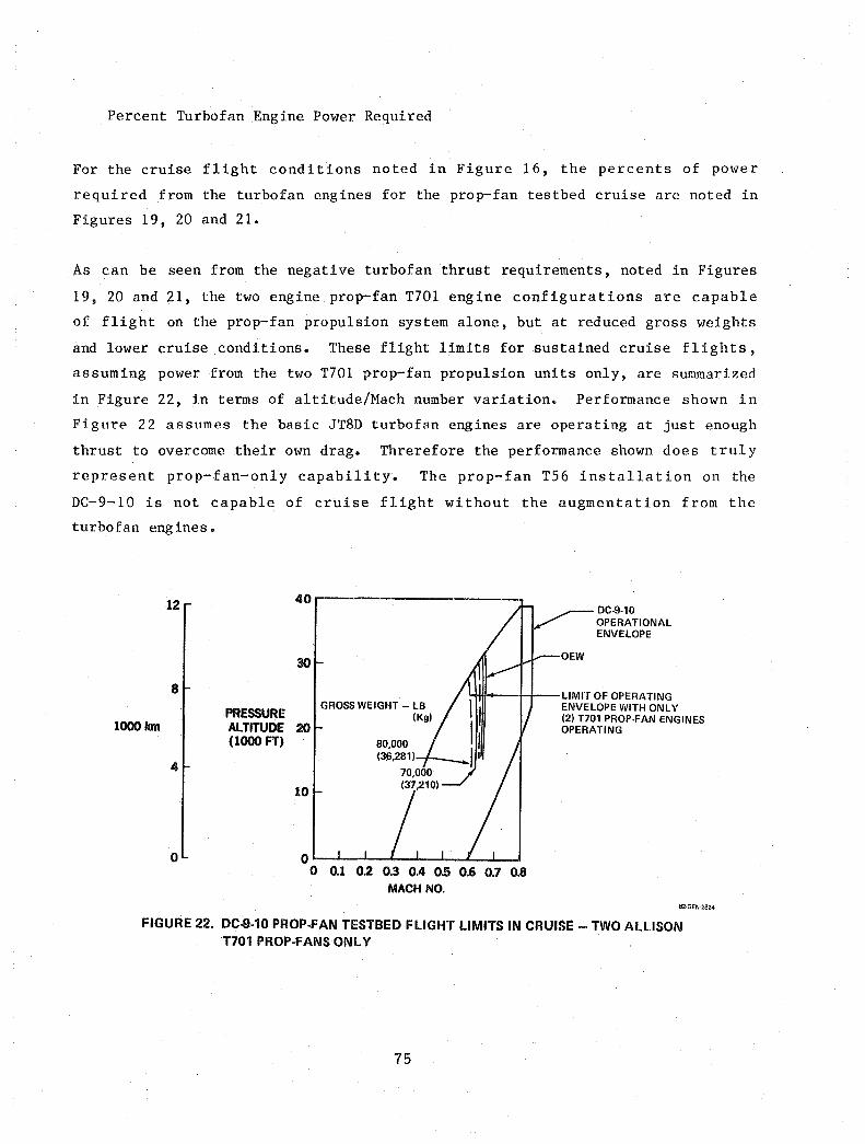
Percent Turbofan Engine Power Required
For the cruise flight conditions noted in Figure 16, the percents of power
required from the turbofan engines for the prop-fan testbed cruise are noted in
Figures 19, 20 and 21.
As can be seen from the negative turbofan thrust requirements, noted in Figures
19, 20 and 21, the two engine prop-fan T701 engine configurations are capable
of flight on the prop-fan propulsion system alone, but at reduced gross weights
and lower cruise conditions. These flight limits for sustained cruise flights,
assuming power from the two T701 prop-fan propulsion units only, are summarized
in Figure 22, in terms of altitude/Mach number variation. Performance shown in
Figure 22 assumes the basic JT8D turbofan engines are operating at just enough
thrust to overcome their own drag. Threrefore the performance shown does truly
represent prop-fan-only capability. The prop-fan T56 installation on the
DC-9-10 is not capable of cruise flight without the augmentation from the
turbofan engines.
12
8
PRESSURE l000km ALTITUDE
(1000 FT)
4
o
40
30
GROSS WEIGHT - LB (Kg)
20 80,000 (36,281)
10
o~~~--~~~~~~~
o 0.1 0.2 0.3 0.4 0.5 0.6 0.1 0.8 MACH NO_
DC-9-l0 OPERATIONAL ENVELOPE
OEW
LIMIT OF OPERATING ENVELOPE WITH ONLY (2) T701 PROP-FAN ENGINES OPERATING
82·GEN·2824
FIGURE 22. DC-9·10 PROP.FAN TESTBED FLIGHT LIMITS IN CRUISE - TWO ALLISON T701 PROP·fANS ONLY
75

ALLISON 1701 ENGINE
ASSUMPTIONS: PROP·FAN AT FULL POWER OEW = 57,000 LB (25,850 kg)
FLIGHT CONDITION
ALTITUDE FT (m)/MCRUISE
35,000 (10,668 m)/0.8M 35,000 (10,668 m)/0.7 30,000 (9,144 m)/0.8 30,000 (9,144 m)/0.6 20,000 (6,096 m)/0.8 20,000 (6,096 m)/0.5
FUEL LOAD = 25,000 LB (11,338 kg)
ONE PROP· FAN TWO PROP·FANS
PERCENT POWER REQUIRED ON TURBOFAN
69-' 56 53 -+ 40 63 .... 56 35 .... 24 66 -+ 63 15 -+ 1
45 .... 32 26-13 38 -+ 31 +5- -6 40 -+ 37
-19 -+ -21 .O·GEN·27416A
FIGURE 19. PERCENT POWER REQUIRED FROM TURBOFAN ENGINES DURING DC·9·10 PROP·FAN CRUISE
ALLISON T56 ENGINE
ASSUMPTIONS: PROp· FAN AT FULL POWER OEW = 57,000 LB (25,850 kg) FUEL LOAD = 25,000 LB (11,338 kg)
FLIGHT CONDITION ONE PROP· FAN TWO PROp· FANS
ALTITUDE FT (m)/MCRUISE
35,000 (10,668 m)/0.8M 35,000 (10,668 m)/0.7 30,000 (9,144 m)/0.8 30,000 (9,144 m)/0.6 20,000 (6,096 m)/0.8 20,000 (6,096 m)/0.5
PERCENT POWER REQUIRED ON TURBOFAN
80 -+ 67 65 -+ 52 64 -+ 50 46 -+ 32 74 ...... 66 58 ...... 51 46 ...... 35 27 ...... 16 19 -+ 76 64 ...... 61 28 ...... 20 7 -+ -1 80·GEN·27415A
FIGURE 20. PERCENT POWER REQUIRED FROM TURBOFAN ENGINES DURING DC-9·10 PROP·FAN CRUISE
FLIGHT CONDITION
ALTITUDE FT (m)/MCRUISE
35,000 (10,668 m)/0.8 M 35,000 (10,668 m)/0.7 30,000 (9,144 m)/0.8 30,000 (9,144 m)/0.6 20,000 (6,096 m)/0.8 20,000 (6,096 m)/0.5
ALLISON T701 ENGINE
ASSUMPTIONS: PROP·FAN AT FULL POWER OEW = 65,000 LB (29,478 kg) FUEL LOAD = 25,000 LB (11,338 kg)
ONE PROP·FAN TWO PROP· FANS
PERCENT POWER REQUIRED ON TURBOFAN
71 ...... 62 53 .... 45 66 -+ 61 36 .... 28 72-70 16 ..... 10
46- 39 26 -+ 18 42- 37 +6- -1 46 .... 44
-20 -+ -28
80·GEN,27417A
FIGURE 21. PERCENT POWER REQUIRED FROM TURBOFAN ENGINES DURING DC·9·30 PROP·FAN CRUISE
76


TASK IV
TESTBED SYSTEM EVALUATION AND RECOMMENDATIONS
The study work delineated by the NASA Contract NAS3-22347 as Tasks II, III, IV
and V are all interdependent. Before an engine prop-fan selection can be made
on a sound basis, the comparative feasibility when installed on a testbed
aircraft must be considered. Therefore, the work of the four tasks have been
necessarily done concurrently. Although the work of integration of the
propulsion system into the aircraft is performed throughout Tasks II, III, and
IV, the discussion of conceptual overall testbed integration is included in
Task v.
TESTBED PROGRAM RECOMMENDATIONS
As a resul t of the work performed in Tasks I through IV, Douglas recommends the
following for the continued prop-fan testbed program:
o DC-9-10 base aircraft.
o T701 turboshaft engine.
o T56 gearbox modified as per Allison recommendation.
o Hamilton Standard 9.5 foot (2.90 m) diameter/IO blade prop-fan.
o 54H60 modified prop-fan control as per Hamilton Standard
recommendation.
o Flight testing of two configurations; namely, the one wing
mounted prop-fan nacelle and the two wing mounted prop-fan
nacelles. In the case of the two prop-fan nacelle
configuration, the prop-fans shall both rotate up and
inboard toward the fuselage.
o Subscale wind tunnel testing, if required, for component design
verification only.
o Large scale flight testing of the DC-9-10 testbed.
Brief discussions follow of the testbed systems evaluation from the
aerodynamics, propulsion, and acoustics points of view.
77
ENGINE SELECTION
As per the initial contract statement of work, the two initially selected
engines, T701 and T56, are to be carried in parallel throughout the study.
However, in the early part of the study, the T701 engine appeared more
desirable; consequently from that point on, the study effort is directed to a
two prop-fan installation utilizing T701 engines. The relative merits of the
T701 versus the T56 engine for the prop-fan testbed are as noted:
T701 Merits versus T56
o Flexibility of free turbine design versus single-shaft
o Variation in power loading, SHP/D2, or tip speed efficiently
accomplished without gearbox rework or change
o Larger diameter prop-fan tested - 9.5 foot (2.90) versus 8.1 foot
(2.46 m)
o Less nacelle blockage to prop-fan 34 percent versus
40 percent
o DC-9 capable of flight on two T701 prop-fans alone
o T701 engine not considered a major risk
A detailed cost comparison between the T701 and the T56 engine is not included
in this study since this side-by-side comparison data are not available from
the engine manufacturer. At this point, the generation of the side-by-side
cost comparison was not considered warranted. Because of its long production
life, the T56 is probably less costly than the T701 engine; however, this cost
factor is not considered adequate to outweigh the other advantages of the T701
as the selected testbed engine.
AERODYNAMIC TESTBED PROGRAM
Subsca1e wind tunnel and flight tests are both required to satisfy the primary
aerodynamic objective of verifying, at flight conditions, the installed
propulsive efficiency of the prop-fan propulsion system. These tests are shown
in the block diagram, Figure 23. Each of these tests is discussed in more
detail in subsequent paragraphs.
78

lI I I I I
-
HIGH SPEED
MODEL: · SUBSCALE DC·9
· POWERED SEMISPAN
· AMES 1 HT OR 14·FT
DATA: CONTOURED WINGINACELLE GEOMETRY
· NET (T·DI · PROP EFFICIENCY · PROP ALIGNMENT · INTERFERENCE DRAG
I . INLET DRAG I INLET INFLUENCE ON PROP
I
INLET TEST
MODEL: SUBSCALE · NASA LEWIS PRT (MODIFIED) NASA LEWIS 8· BY 6·fT TUNNEL
DATA:
· INLET CONTOURS · COMPRESSOR FACE DISTORTION · INLET DRAG EFFECT OF INLET ON PROP
lOW SPEED
MODEL: · SUBSCALE - COMPLETE SPAN EXISTING DC·9 · POWERED lJ.1N. (27.9 eml PROP
· AMES 12·FT
DATA:
· STALL SPEEDS · FLAP SETTING LONGITUDINAL STABILlTY& CONTROL LATERAL· DIRECTIONAL STABILITY
FLIGHT rEST
MODEL: DC·9
i--DATA:
STATIC ENGINE INLET . NET (T·DI PROP EFFICIENCY
COMPATIBILITY TEST . INTERFERENCE DRAG
- -LARGE·SCALE TESTS I IN 40· BY 80·FT TUNNEL AT LOW FORWARD SPEED I CORRELATION WITH I
SUBSCALE DATA
I t __________________________________________ J
FIGURE 23. AERODYNAMIC TEST PLAN SUMMARY
High Speed Wind Tunnel Test
A high speed wind tunnel test program will be conducted using a DC-9 semi-span
wing model with an air driven turbine to power the propeller. It may be
possible to use the air turbine already developed at NASA Ames. The objective
is to develop an efficient nacelle/wing geometry that has low drag in the
presence of the propeller flow. Any transonic tunnel can be used, preferably
the NASA Ames 14-foot facility. A sketch of a typical installation is shown in
Figure 24.
DRIVE SHAFT T, qAND RPM
WING SURFACE STATICS
~PROPELlER PLANE RAKE
_~PS' AND "FLO c=---"If.-- :=>
~"'''''. STATICS
.
DATA TO BE OBTAINED
• AIRCRAFT LIFT, DRAG, AND PITCHING MOMENTS
• DRAG OF DIFFERENT NACELLE/WING CONTOURED SHAPES
• PROPELLER LOADS AT DIFFERENT ORIENTATIONS RELATIVE TO AIRCRAFT
• INSTALLED PROPULSION EFFICIENCY (NET THRUST MINUS DRAG)
• PROPELLER EFFICIENCY IN PRESENCE OF AIRCRAFT
• PROPELLER INFLOW VELOCITIES AND ANGLES FOR PROPELLER DESIGN
• AIRCRAFT FLIGHT BOUNDARIES (BUFFET AND C
LMAX)
• AIR LOADS (FROM SURFACE STATIC PRESSURES)
81·GEN·21835 A
FIGURE 24. HIGH-SPEED WIND TUNNEL MODEL
79

The data to be obtained are noted on Figure 24. More than one entry into the
wind tunnel may be required to develop the geometry. After initial data are
obtained, analysis of the data will be conducted and geometry modifications
will be developed. Different nacelle contours and wing shapes will be tested.
The following configurations will be tested:
o clean wing
o wing plus nacelle
o wing plus nacelle plus prop-fan
These testbed specific configurations are the same as those to be used later in
the flight test pr6gram and the purpose and use for each configuration is
discussed in subsequent paragraphs of Task IV relative to the flight test
program. Data from these tunnel tests will be useful in defining the
propulsive efficiency and drag terms as noted:
where
(T-D) :
T:
Buoyancy:
Drag:
(T-D) T + Buoyancy + TNOZ
- Drag
net thrust minus drag of the complete configuration obtained
from floor mounted balance.
thrust of prop-fan obtained from prop-fan drive shaft
balance.
the axial force obtained from an integration of nacelle
surface static pressures with prop-fan operating and
prop-fan off.
turbine drive nozzle thrust obtained by calibration of the
nozzle.
drag of the configuration - obtained by taking the
difference between the clean wing and the configuration with
the propulsion system installed.
80

Since the turbine is powered from an external air supply source, there will not
be a turboshaft engine air inlet on the nacelle as there will be for the flight
installations. The effect of the inlet on the external drag, the prop-fan
loads, and performance will not, therefore, be included in the high speed wind
tunnel data. (The effect of the inlet on the prop-fan and inlet drag without
the influence of the aircraft can be determined during the inlet development
phase of the inlet tunnel test program.) This is a limitation of the high
speed wind tunnel test data; and the inlet effect is therefore an item that
must be evaluated during the flight test phase with the large scale hardware.
The "no inlet" geometry cannot be flight tested for comparison to the wind
tunnel data; therefore, the effects of the inlet and flight effects relative to
the high speed wind tunnel data will have to be carefully studied. The effect
of the inlet on aerodynamic performance is not anticipated to be large.
The subscale high speed wind tunnel test is the preferred method of developing
an efficient shape for the wing and nacelle to be evaluated during flight.
Multiple geometries can be tested in the tunnel and the appropriate diagnostic
data taken much more efficiently than in flight. The fundamental questions bf
the installation (for instance - how large are the effects of nacelle
contouring on wing pressures) can be quickly and less expensively resolved in
the wind tunnel as opposed to doing the same thing in flight.
The instrumentation required for the high speed wind tunnel testing is similar
to that recommended for flight test and is summarized in the following
tabulation:
INSTRUMENTATION PURPOSE
0 Floor balances 0 to measure configuration lift, drag, and pitching moment.
0 Prop-fan drive shaft RPM 0 prop-fan thrust and efficiency thrust and torque and aircraft drag.
0 Nacelle surface statics 0 drag analysis and buoyancy correction.
0 Wing surface statics 0 drag analysis.
0 Prop-fan plane rake, PTOTAL 0 input to prop-fan design. PSTATIC and flow angle
81

Low Speed Wind Tunnel Test
Following the high speed wind tunnel testes), the preferred high speed
configuration will be tested at low speed. The objective is to determine the
stall speeds and flap settings for safe operational flight during takeoff and
landing.
Prop-fan windmilling conditions consistent with the flight test takeoff
procedure will be tested. Effects of power at low speed will be determined by
using an air-driven turbine to power the prop-fan. A new turbine with a 13
inch (3.30 cm) prop-fan will be required. An appropriate low speed facility is
the Ames 12-foot tunnel. Douglas has an existing complete span DC-9 Clodel that
can be modified for use in this facility. Figure 25 presents a photograph of
this Douglas DC-9 model mounted in the NASA Ames 12-foot 10\., speed pressure
tunnel along with a summary of the data to be obtained.
DATA TO BE OBTAINED
• AIRCRAFT LIFT. DRAG. AND PITCHING MOMENT WITH AND WITHOUT YAW
• STALL SPEEDS AND CHARACTERISTICS
• CLMAX
• APPROPRIA TE FLAP SETTINGS
• LONGITUDINAL STABILITY AND CONTROL
• LATERAL-DIRECTIONAL STABILITY AND CONTROL
81-GEN-21834
FIGURE 25. LOW-SPEED WIND TUNNEL
82

These data will be used to placard the aircraft so that safe flight operation
will be obtained during low speed, low altitude flight. For instance, the
present conservative restriction of prop-fan operation at 15,000 feet (4,512 m)
or above, noted in Figure 15, will be resolved and perhaps lowered or removed
as a result of these low speed wind tunnel tests. The wind tunnel
instrumentation required is not extensive. All that is needed is the six
component balance data and perhaps some flow visualization equipment.
Inlet Development
The engine inlet contours will be developed concurrently with the aircraft
configuration development. The objective is to develop an inlet configuration
which, when operating in the presence of the rotating prop-fan, gives
acceptable steady-state and time-dependent total pressure distortion at the
engine compressor face. The propeller test rig (PRT) developed at NASA Lewis
for use in the 8 x 6-foot transonic wind tunnel may be used for the tes t ing. A
modification to offset the drive shaft of the PRT will be required to properly
scale the inlet capture area to the prop-fan and to properly model the duct
offset geometry. A sketch of a typical installation is shown in Figure 26 •
Several inlet duct geometries will be tested until distortion levels are within
satisfactory levels as established by the engine manufacturer. Following the
sub scale wind tunnel test, the selected inlet duct geometry will be ground
tested on the engine by the engine manufacturer.
COMPRESSOR FACE RAKE - STEADY STATE
~ AND DYNAMIC TOTAL ~ PRESSURE .
SURFACE STATIC S ~ RAKE FOR INLET DRAG PRESSURES PT AND Ps
DATA TO BE OBTAINED
• STEADY-STATE COMPRESSOR FACE DISTORTION
• TIME-DEPENDENT COMPRESSOR FACE DISTORTION
• INLET INFLUENCE ON PROPELLER BLADE STRESSES
• INLET DRAG INCREMENT
FIGURE 26. INLET TESTING
83

The subscale wind tunnel test program will also establish the effects of the
inlet on the prop-fan loads and the drag of the inlet. The effect on the
prop-fan will be found by running with and without the inlet present and
measuring the difference in blade stresses. The inlet drag will be found by
placing total and static pressure instrumentation downstream of the inlet face
on the external cowl surface. The estimated location of the instrumentation on
the wind tunnel model is indicated in Figure 26; and the instrumentation
considered for this phase of inlet testing is tabulated as follows:
* o
* o
o
o
o
*
INSTRUMENTATION
Compressor face steady state total pressure rake
Compressor face time dependent transducers
Internal duct static pressures
External static pressures
External total rakes
o
o
o
o
o
PURPOSE
steady state total pressure distortion.
time dependent (dynamic) total pressure distortion.
inlet distortion analysis.
inlet drag analysis.
inlet drag analysis.
Location and number of probes to be defined in conjunction with engine manufacturer.
84
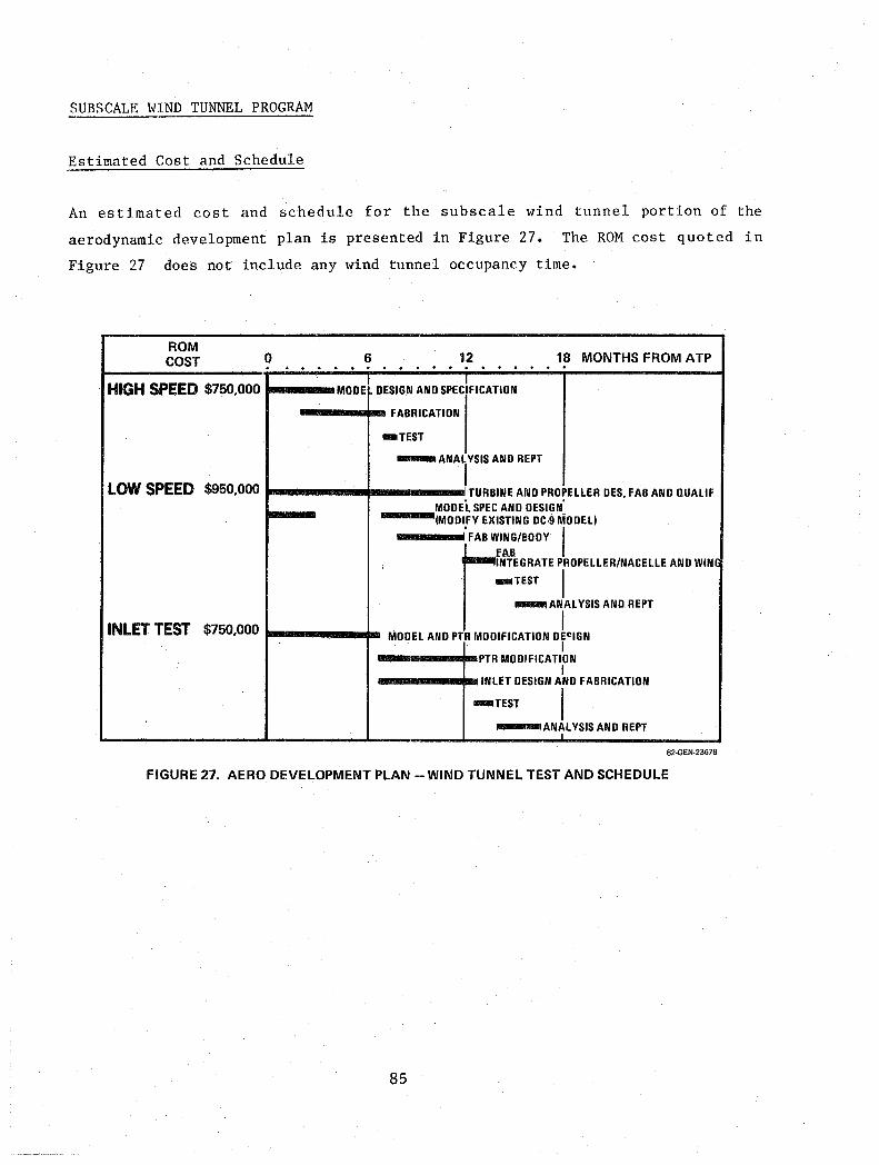
SUBSCALE WIND TUNNEL PROGRAM
Estimated Cost and Schedule
An estimated cost and schedule for the subscale wind tunnel portion of the
aerodynamic development plan is presented in Figure 27. The ROM cost quoted in
Figure 27 does not include any wind tunnel occupancy time. .
ROM COST o 6 12 18 MONTHS FROM ATP .. ..... ..
HIGH SPEED $750,000 t--_ .. MODEl DESIGN AND SPEciFICATION
---.... FABRICATION
-TEST
-,ANAL YSIS AND REPT
LOW SPEED $950,000 1-----.. -----, TURBINE AND PROPELLER DES, FAB AND nUALIF MODEL SPEC AND DESIGN'
---(MODIFY EXISTING DC·9 MODEL)
I'" ~::IBODY I " INTEGRATE PROPELLER/NACELLE AND WIN.
IIIIIIIIHEST I _ ANALYSIS AND REPT
I INLET TEST $750,000 t-----.. MODEL AND PTR MODIFICATION DE~IGN I
---_ ..... IIIIIIPTR MODIFICATION I
----"",I11III INLET DESIGN AND FABRICATION
-TEST I -ANAL YSIS AND REPT
82·GEN·23678
FIGURE 27. AERO DEVELOPMENT PLAN - WIND TUNNEL TEST AND SCHEDULE
85

Flight Test
After the high and low speed wind tunnel tests, as well as the necessary ground
testing, have been conducted and the inlet/engine compatibility tests
completed, the flight test phase of the program can be initiated. Figure 23
delineates the major aerodynamic aspects of the flight test program. During
the high speed wind tunnel tests, the aerodynamnic effectiveness of a contoured
nacelle installation under consideration will be determined. Provided
structural, performance, and cost trade studies verify the overall advantages
and feasibility of the contoured nacelle, the DC-9 aircraft will be modified to
accept the contoured nacelle installation. Also, the minimum aircraft flight
speeds will be properly placarded. Major discussions of the mechanics of the
flight test program are included in Task VI, however, aerodynamic aspects of
the flight testing are included herein (Task IV) as part of the aerodynamic
testbed systems evaluation.
From the aerodynamic point of view, the primary purpose of the ground, wind
tunnel and flight testing is to obtain the net installed thrust-minus-drag of
the wing-mounted propulsion system. The appropriate aerodynamic data to be
obtained during the flight testing are listed as follows:
o Speed and altitude
o DC-9 JT8D-7 turbofan engine thrust
o RPM, thrust, and torque of prop-fan drive shaft
o Surface static pressures (nacelle and wing)
o Prop-fan plane rake static and total pressures and flow angle
o
o
o
o
Internal inlet duct static pressures
Load factors nand n z y Control positions - d ,d, d cc w r Airplane attitude and rate of pitch, e & ~; roll ¢ & ~; yaw 0/ & ~
o Airplane angle of attack - a
o Airplane sideslip B
86

These data will then be used to extend the wind tunnel results and analytical
estimates to actual flight conditions for the prediction of full scale prop-fan
aircraft performance. The prop-fan thrust will be obtained to verify the
Hamilton Standard data and to form the reference level for the Douglas
thrust/drag bookkeeping system.
Basic Data Acquisition
The basic DC-9-10 engine, JT8D-7 turbofan, must be calibrated to determine the
thrust characteristics at flight speeds. This calibration will be conducted in
a manner acceptable to NASA, Douglas, and Pratt & Whitney.
The basic DC-9 will be flown to establish the reference drag level for the
thrust-minus-drag measurements. The suggested flight envelope to be used is
shown in Figure 28 and the six specific flight test points selected are shown.
These six points will be flown, and the thrust of the calibrated engines will
be used to determine the drag for this and all other configurations.
(12) 40
- -30 E t: 8 (8) 8 .... .... - - 20 IJ.I LLI C C ::,:) ::> I- .... i= (4) 5 ...I 4(
4( 10
I (0) 0.1
~,,, ." ,,' " «~/. ." 0/
.~/ . ~'/
(b ...... tlf..lf).'/ \.:;{
~/ #/ ,.//
~1 /#"
~I / ~~. / I . I
I .
;1 I , I
0.2 0.3
/
I I
I I
0.4
I
I
0.5
Mo
,- 4~ ,-,-
1" "TESTBED / FLIGHT V / ENVnOPE-
V
/ V
0.6 0.7 0.8 I
0.9
80 GEN·27500A
FIGURE 28. DC-9 AIRCRAFT OPERATING POINTS ASSUMED IN PERFORMANCE SPECTRUM
87

The nacelle installation with the prop-fan removed will then be installed in
the testbed aircraft and be flown. The inlet and nozzle will be faired over to
eliminate the nozzle base drag and momentum losses of the air flowing through
the windmilling engine. Surface pressure data on the nacelle will be recorded
in addition to the thrust (drag) data to form the baseline pressure levels for
buoyany corrections to the prop-fan force data. The drag data will be used to
determine the interference drag of the nacelle on the wing without the prop-fan
flow effects. When compared to the prop-fan on data with power, these data
will isolate the effects of power from the effects of the nacelle. The more
significant effects can be isolated and, for different prop-fan or nacelle
geometries, the drag interference factors of each component will be known for
application to other configurations.
The inlet fairing presents a problem in that the fairing will disturb the
pressures used in the buoyancy correction. The design of the fairing must be
carefully tailored using 3-D surface panel potential theory to minimize
differences from that of the inlet when operating with flow into the engine.
Different fairing shapes will be studied until pressure distributions on the
nacelle are similar to those predicted by the program with the flowing inlet
represented. If pressure differences exist for the selected fairing shape,
then the increments will be used to adjust the measured pressure levels to
those of a flowing inlet to obtain reference levels for buoyancy corrections.
The prop-fan will then be installed on the drive system and operated at several
power levels. During this phase of the testing, the JT8D-7 engine thrust,
obtained from the calibration discussed previously, will be used to establish
the net thrust of the prop-fan minus drag. Prop-fan thrust, torque, and RPM
will be measured using prop-fan drive shaft instrumentation; and nacelle static
pressures will be measured so that nacelle buoyancy corrections can be made to
the prop-fan thrust.
The data will be used to define the various terms in the following equation:
(T-D) TINST + Buoyancy + TNOZ Drag
88
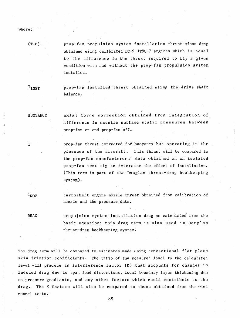
where:
(T-D)
BUOYANCY
T
DMG
prop-fan propulsion system installation thrust minus drag
obtained using calibrated DC-9 JT8D-7 engines which is equal
to the difference in the thrust required to fly a given
condition with and without the prop-fan propulsion system
installed.
prop-fan installed thrust obtained using the drive shaft
balance.
axial force correction obtained from integration of
difference in nacelle surface static pressures between
prop-fan on and prop-fan off.
prop-fan thrust corrected for buoyancy but operating in the
presence of the aircraft. This thrust will be compared to
the prop-fan manufacturers' data obtained on an isolated
prop-fan test rig to determine the effect of installation.
(This term is part of the Douglas thrust-drag bookkeeping
system).
turboshaft engine nozzle thrust obtained from calibration of
nozzle and the pressure data.
propulsion system installation drag as calculated from the
basic equation; this drag term is also used in Douglas
thrust-drag bookkeeping system.
The drag term will be compared to estimates made using conventional flat plate
skin friction coefficients. The ratio of the measured level to the calculated
level will produce an interference factor (K) that accounts for changes in
induced drag due to span load distortions, local boundary layer thickening due
to pressure gradients, and any other factors which could contribute to the
drag. The K factors will also be compared to those obtained from the wind
tunnel tests. 89
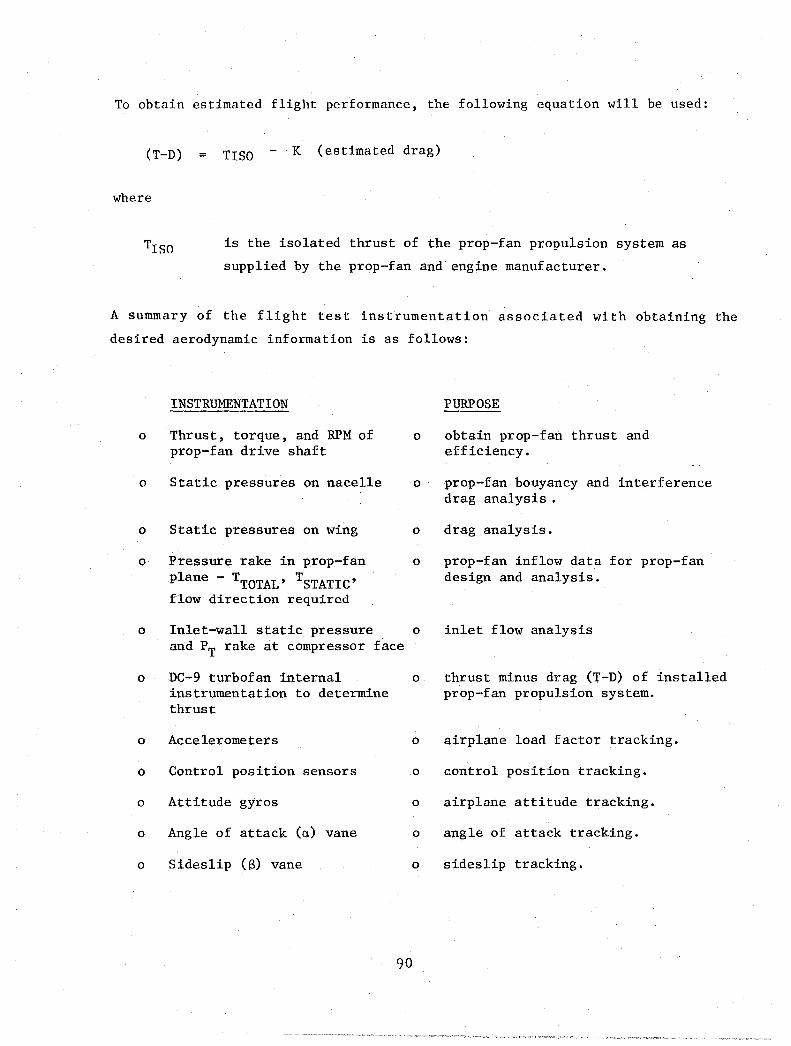
To obtain estimated flight performance, the following equation will be used:
(T-D) = TISO K (estimated drag)
where
Trso is the isolated thrust of the prop-fan propulsion system as
supplied by the prop-fan and engine manufacturer.
A summary of the flight test instrumentation associated with obtaining the
desired aerodynamic information is as follows:
INSTRUMENTATION
o Thrust, torque, and RPM of 0
prop-fan drive shaft
o Static pressures on nacelle 0
o Static pressures on wing 0
o Pressure rake in prop-fan 0
plane - TTOTAL' TSTATIC' flow direction required
o Inlet-wall static pressure 0
and PT rake at compressor face
o DC-9 turbofan internal 0
instrumentation to determine thrust
o Accelerometers 0
o Control position sensors 0
o Attitude gyros 0
o Angle of attack (a) vane 0
o Sideslip (8) vane 0
90
PURPOSE
obtain prop-fan thrust and efficiency.
prop-fan bouyancy and interference drag analysis .
drag analysis.
prop-fan inflow data for prop-fan design and analysis.
inlet flow analysis
thrust minus drag (T-D) of installed prop-fan propulsion system.
airplane load factor tracking.
control position tracking.
airplane attitude tracking.
angle of attack tracking.
sideslip tracking.

A sketch of the location of the proposed instrumentation for installed
propulsion system performance is given in Figure 29.
CONTROL POSITIONS AIRCRAFT ATTITUDE
NACELLE SURFACE STATICS
:~7 .-.~
SHAFT BALANCE T,a, AND RPM
LNG SURFACE STATIC PRESSURES (UPPER AND LOWER SURFACE)
FIGURE 29. CRUISE PERFORMANCE PRESSURE SURVEY INSTRUMENTATION
91
81·GEN·21850A

PROPULSION SYSTEM - PROP-FAN/T701 ENGINE INTEGRATION
Figures 30 and 31 present preliminary sketches of the T701 engine/ prop-fan
installations. The engine is installed above and forward of the wing front
spar. The engine tailpipe is routed over the upper wing surface and exits at
the wing trailing edge. The three section cuts (Figure 31) are through the
nacelle at the forward (gearbox) mount, aft engine mount, and between the
gearbox and engine proper.
PROPELLER CONTROL
FORWARO ENGINE MOUNT PLANE (V N = 60.288)
REDUCTION GEAR BOX (MODIFIED FROM DDA T·56)
REDUCTION GEAR BOX OIL TANK
REDUCTION GEAR BOX OIL COOLER VN = 110.000
01 L TANK FOR ENGINE LUBE SVSTEM FIRESEAL
AFT ENGINE MOUNT PLANE (V N = 156.146 ROOM TEMP)
C TAIL PIPE ASPIRATOR
ENGINE EXHAUST TAIL PIPE
REMOVABLE TAIL PIPE SECTION FOR ENGINE REPOSITIONING
HORIZONTAL Il OF NACELLE
TAIL PIPE EXIT PLANE
OC·9·30 WING AIRFOIL AT X = 222.000 (TRACE)
4.0 FT (MOl STATIC GROUND CLEARANCE LEFT SIDE PROFILE VIEW LOOKING NORMAL _~J ____ ~~~~DC-9-30STATICGROUNDLINE
FIGURE 30. T701 ENGINE/PROP·FAN INSTALLATION
HORIZONTAL It OF NACELLE) REDUCTION GEAR BOX OIL COOLER
ENGINE VERTICAL It""
ENGINEI NACELLE INTERFACE-'C-~~
LOWER LONGERON PLANE
REDUCTION GEAR BOX OIL TANK
A·A LOOKING AFT
FORWARD ENGINE MOUNT
. {ENGINE HORIZONTAL It
i D·D LOOKING FORWARD
8O·GEN·27515
C.c LOOKING FORWARD SHOWING AFT ENGINE MOUNT .' SHOWING FORWARO ENGINE MOUNTS
',,"- 8O·GEN·21516
FIGURE 31. T701 ENGINE/PROP·FAN INSTALLATION (CONTINUED)
92

The prop-fan installation and systems characteristics are itemized as follows:
o DDA T70l SHAFT HORSEPOWER ENGINE COUPLED WITH A MODIFIED DDA T-56 GEARBOX
o GEARBOX MODIFICATION REQUIRED
o Reverse input rotation (main gears o.k.) o Oil system modification (due to rotation) o Propeller brake (for feathered prop in flight)
o GEARBOX OIL TANK AND COOLER INDEPENDENT OF ENGINE AND MOUNTED IN FIXED STRUCTURE
o EXISTING OIL TANK AND COOLER ON ENGINE UTILIZED FOR ENGINE ONLY
o OFF-THE-SHELF PNEUMATIC STARTER USED
o HARD ENGINE MOUNTS PROVIDED, BUT SPACE AVAILABLE FOR SHOCK MOUNTS
o ENGINE MOUNTS FAIL-SAFE
o PART OF INLET SCOOP BUILT INTO LOWER DOOR
o ACCESSORY AND TURBINE COMPARTMENT SEPARATED BY FIRE SEAL
o FIRE EXTINGUISHING (TWO-SHOT) SYSTEM PROVIDED
o FIRE WARNING (FIRE DETECTORS) PROVIDED
o UPPER PORTION OF NACELLE AND WING FIRE PROTECTED
o FIREWALL FUEL SHUTOFF LOCATED CLOSE TO FUEL TANK BULKHEAD
o HOISTING PROVISIONS IN UPPER NACELLE STRUCTURE ALLOW ENGINE AND GEARBOX TO BE REMOVED OR INSTALLED AS A UNIT (STRUCTURAL BREAK AFT OF REAR MOUNT)
o SMALL ACCESS DOORS IN UPPER NACELLE FOR OIL FILLING, INSPECTION, AND BORES COPE INSERTION
o OIL TANK SCUPPER DRAINS TERMINATE IN A DRAIN MAST
o CRITICAL OIL AND FUEL SEAL DRAINS ALSO ROUTED TO THE DRAIN MAST
o VIBRATION'PICKUPS INSTALLED (PROBABLY TRACKING FILTER TYPE)
o PROVISIONS COULD BE MADE TO MOVE ENGINE AND PROP-FAN RELATIVE TO WING LEADING EDGE (REMOVABLE PLUG IN NACELLE STRUCTURE AFT OF REAR ENGINE MOUNT AND ATTACH BULKHEAD
o SYSTEMS OR COMPONENTS WHICH CAN BE DELETED IN THE INTEREST OF COST SAVING
o Generator o Hydraulic pumps or system o Environmental bleed systems or controls o Anti-icing system on inlet or prop o Remote oil quantity indicator.
93

Fuel System
The fuel system connection between the basic DC-9 aircraft fuel system and the
prop-fan installation is shown in Figure 32. This particular drawing
represents a one prop-fan/engine installation; the same type installation on
the other aircraft wing is required for the two prop-fan arrangement. As can
be seen, the fuel line is connected into the basic aircraft fuel system between
the two boost pumps in the main wing fuel tank. The fuel line is then routed
through the front wing spar to a firewall shut-off valve and then to the fuel
connection on the fuel control of the T701 engine.
RIGHT MAIN TANK
CENTER TANK
JT8D ENGINE
FIGURE 32. DC-9 PROP-FAN FLIGHT TESTBED FUEL SYSTEM aO-GEN·27437
Opposite Rotation
Investigation of the gains, both aerodynamically and acoustically, of
installing both the prop-fans to rotate up and inboard to the fuselage also
entails a trade study of the engine manufacturer to evaluate the complexity and
cost of providing the engine gearbox with capability to permit opposite
prop-fan rotation. In general, such an arrangement is felt to be quite
feasible; a detailed study of such opposite rotation is currently underway by
Allison.
94

Other operational considerations associated with the prop-fan opposite rotation
include the
o clockwise and counter-clockwise swirl from the prop-fan, and
o cyclic prop-fan frequency dynamic distortion.
Consequences of these operational results may entail such as
o one inlet design for a "worst case" or separate inlets for right and
left hand installations,
o different left and right hand engine operation from the points
of view of performance or transient operations,
o inlet guide vane tailoring for each engine.
These operational considerations warrant further investigation before testbed
flight.
Key Characteristics of Prop-fan Propulsion System
The key characteristics of the testbed prop-fan propulsion system, based on the
work performed during Task I through V are summarized as follows:
o T701 with modified T56 gearbox is the most suitable prop-fan drive
for the NASA testbed.
o The largest diameter prop-fan available (T701 engine capaility of
swinging a 9.5 foot [2.90 m] diameter prop-fan) is compatible with
Hamilton Standard recommendations.
o Hamilton Standard recommends use of a modified 54H60 prop-fan
control.
o Allison recommends use of a modified T701 engine control.
o The prop-fan drive can be installed on a DC-9 wing.
o An inlet testing must be developed before proceeding with the
testbed flights
o A prop-fan/engine control coordinator may be required for flight
test particularly on the two-engine prop-fan installation).
95

ACOUSTIC TESTBED PROGRAM
The acoustic technology objectives identified in Task I are listed here for
convenience in order of priority:
o Primary Objectives
o Determine prop-fan near field and far field noise
characteristics during representative ground and flight
conditions.
o Determine passenger cabin noise characteristics and fuselage
vibration transmission during cruise flight.
o Determine the effectiveness of various cabin noise
control treatments.
o Secondary Objectives
o Evaluate effects of prop-fan opposite rotation and
synchronization on noise characteristics.
o Determine effects of scaling model prop-fan acollstic data to
large scale applications with flight effects.
o Obtain acoustic data to verify or modify existing theoretical
prediction models.
o Obtain acoustic data to develop and verify procedures for
predicting FAR Part 36 noise levels.
The production DC-9 turbofan fuselage sidewall acoustic treatment is shown in
Figure 33. This sidewall configuration will not provide sufficient
attenuation to meet the selected interior noise goal on the testbed aircraft.
Therefore, treatment modifications must be identified that will meet this goal.
A laboratory test program to identify promising treatment designs is described
in a subsequent section.
Resolution of Acoustic Technology Objectives
The possibility of accomplishing the acoustic technology objectives by a
program which includes high and low speed wind tunnel and static test stand
work is discussed in Task I and is summarized in Figure 34.
96
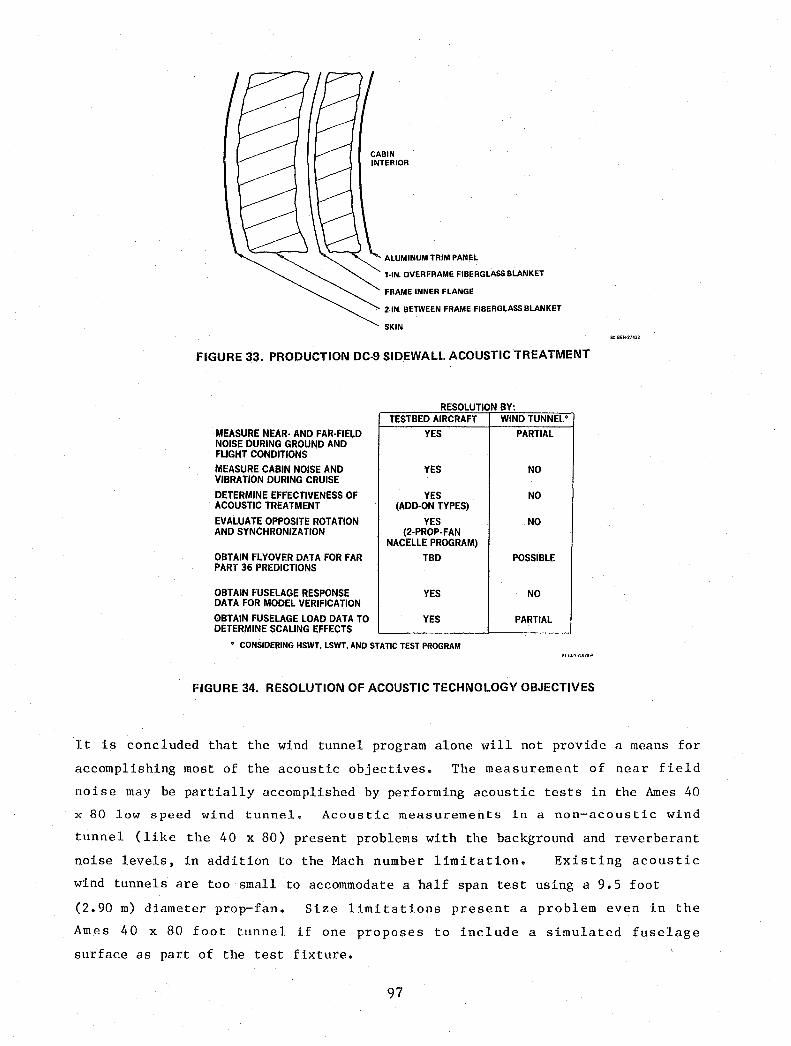
CABIN INTERIOR
ALUMINUM TRIM PANEL
1-IN. OVER FRAME FIBERGLASS BLANKET
FRAME INNER FLANGE
2·IN. BETWEEN FRAME FIBERGLASS BLANKET
SKIN
FIGURE 33. PRODUCTION DC-9 SIDEWALL ACOUSTIC TREATMENT
RESOLUTION BY'
MEASURE NEAR· AND FAR-FIELD NOISE DURING GROUND AND FLIGHT CONDITIONS
MEASURE CABIN NOISE AND VIBRATION DURING CRUISE
DETERMINE EFFECTIVENESS OF ACOUSTIC TREATMENT
EVALUATE OPPOSITE ROTATION AND SYNCHRONIZATION
OBTAIN FLYOVER DATA FOR FAR PART 36 PREDICTIONS
OBTAIN FUSELAGE RESPONSE DATA FOR MODEL VERIFICATION
OBTAIN FUSELAGE LOAD DATA TO DETERMINE SCALING EFFECTS
TESTBED AIRCRAFT
YES
YES
YES (ADD-ON TYPES)
YES (2·PROp·FAN
NACELLE PROGRAM)
TBD
YES
YES
• CONSIDERING HSWT. LSWT, AND STATIC TEST PROGRAM
WIND TUNNEL'
PARTIAL
NO
NO
NO
POSSIBLE
NO
PARTIAL
FIGURE 34. RESOLUTION OF ACOUSTIC TECHNOLOGY OBJECTIVES
It is concluded that the wind tunnel program alone will not provide a means for
accomplishing most of the acoustic objectives. The measurement of near field
noise may be partially accomplished by performing acoustic tests in the Ames 40
x 80 low speed wind tunnel. Acoustic measurements in a non-acoustic wind
tunnel (like the 40 x 80) present problems with the background and reverberant
noise levels, in addition to the Mach number limitation. Existing acoustic
wind tunnels are too small to accommodate a half span test using a 9.5 foot
(2.90 m) diameter prop-fan. Size limitations present a problem even in the
Ames 40 x 80 foot tunnel if one proposes to include a simulated fuselage
surface as part of the test fixture.
97

However, measurement of near field noise during half span testing in the 40 x
80 foot wind tunnel without a simulated fuselage surface is a possibility,
although the data quality will probably be marginal. Absolute levels of
prop-fan noise measured in this manner will be unreliable; but the data will be
useful for examining noise trends with variations in measurement location,
installation geometry, and operating conditions. Static test stand acoustic
measurements on an open propeller rotor have been shown to give unpredictable
results because the flow field of a static propeller or fan greatly modifies
the structure of turbulence present in the atmosphere. Spurious random sources
are then created when blades encounter the turbulence. Some sophisticated data
analysis techniques, designed to separate random and periodic noise, have been
used on static propeller noise (Reference 4). The utility of the methods has
not been established, however, since no direct comparison of data so reduced
has ever been made with flight data. Test stand measurements are also
incomplete because they do not include local flow field modification by the
presence of the aircraft, have incorrect relative velocities between the
airstream and the blades, and have different convective amplification effects
than the free flight case.
Other acoustic objectives which have some possibility of resolution by a static
test stand and wind tunnel program alone are the determination of scaling
effects and the measurement of far field noise for development of FAR Part 36
predictions. However, these objectives would suffer from the same problems
mentioned above. The remaining objectives have no possibility of being
accomplished with a wind tunnel program. Subsequent discussion will,
therefore, be confined to resolution of acoustic objectives by a testbed
aircraft flight program. Resolution of all acoustic technology objectives
could be accomplished with a program which includes laboratory testing of
acoustic treatment designs, and ground static testing, taxi testing, and flight
testing with a two prop-fan system mounted on a testbed aircraft. The elements
of this program are shown in Figure 35. In the case of the outdoor test stand,
the measurement of near and far field noise is dependent upon the facility
selected for the static testing.
98

Level flyovers at ~ 2,000 feet (610 m) altitude are desired; however, these
flyovers are contingent upon the flight envelope restriction discusssed in Task
III and in the aerodynamic testing of this Task IV.
LABORATORY TESTING IDENTIFY BASELINE SIDEWALL ACOUSTIC TREATMENT
• IDENTIFY ADDITIONAL PROMISING TREATMENT DESIGNS
OUTDOOR TEST STAND PROP-FAN/ENGINE/GEARBOX/NACELLE SYSTEM MEASURE NEAR- AND FAR-FIELD NOISE
GROUND RUNUP AND TAXI TESTING TWO PROP-FAN SYSTEMS INSTALLED ON AIRCRAFT
• MEASURE NEAR-FIELD. FAR-FIELD. AND INTERIOR NOISE
FUSELAGE EXTERNAL ACOUSTIC LOADS
INTERIOR NOISE
ALTITUDE MACH NUMBER
• TIP SPEED
BLADE PASSAGE FREQUENCY PROP-FAN POWER LOADING BLADE ANGLE
• BASELINE ACOUSTIC TREATMENT • ADDITIONAL TREATMENT DESIGNS (ALSO BARE WALL)
VARIOUS OPERATING CONDITIONS OPPOSITE ROTATION SYNCROPHASER EVALUATION SELECTED FLIGHT CONDITION
CABIN ABSORPTION MEASURE REVERBERATION TIMES FOR BARE-WALL AND TREATED CONFIGURATIONS
FIGURE 35_ ACOUSTIC TEST REQUIREMENTS
Laboratory Testing
Laboratory testing will be performed in an acoustic facility and will be used
to identify a baseline acoustic treatment design. The baseline treatment will
be of the add-on type (no changes to aircraft fuselage structure) and will be
the most efficient sidewall design identified in the test program; this program
will provide the transmission loss predicted to be necessary to achieve a
selected interior noise goal on the testbed aircraft. Additional promising
treatment designs will also be identified in the lab test program; a design
incorporating change to the outer fuselage structure will be included. Some of
the acoustic treatment changes that will be investigated during the laboratory
test program are shown in Figure 36 and 37.
99

FIGURE 36. ISOGRID STRUCTURE
TREATMENT MODIFICATIONS
1. OUTER STRUCTURE
a. NO ADDITIONAL DAMPING
b. VISCOELASTIC TREATMENT ON SKIN I. 2. BLANKET SYSTEM .1 CABIN .. INTERIOR
a. NO SEPTUM
b. OVER FRAME LEAD SEPTUM
3. HONEYCOMB TRIM PANEL
a. OVER FRAME LEAD SEPTUM (AS IN 2b)
b. LEAD ADDED TO TRIM PANEL BACKSHEET
81·0C9·91238
FIGURE 37. MODIFIED SIDEWALL ACOUSTIC TREATMENT
100

Outdoor Test Stand
Outdoor test stand acoustic measurements on an open rotor have significant
problems as mentioned previously. However, assuming the prop-fan/engine/
gearbox/nacelle system will be run on a test stand with acoustic measurement
capability, it is proposed to obtain near field and far field acoustic data at
the same time as the other static testing, Figure 38.
160" (2.79)
150" (2.62)
140" (2.44)
130"
:-J:=--c:::::::~:;:::::==------t(R~DIANS)
(2.27) 120"
(2.09) UOO 1000 80" 700 (1,04) (1.92)(1.75) (ri7)(1.40)(1.22)
III = MICROPHONE LOCATION PROP PLANE
OUTDOOR TEST STAND FACILITY AT QUARTZSITE. ARIZONA
FIGURE 38. MEASUREMENT OF NEAR-AND FAR-FIELD NOISE ON OUTDOOR TEST STAND
This test will be useful for two reasons. The data may provide advance
information of fuselage acoustic loading and community noise representative of
conditions at brake release. The static test stand measurements may also
provide a valuable data base for future investigations which rely on static
acoustic data to predict in-flight noise. The ability to use static data may
become important when the prop-fan system achieves production status because
the airframer must understand the situation with regard to noise certification
of the aircraft prior to construction. The alternative to using static
acoustic data is the use of purely theoretical techniques, which may not
inspire the same level of confidence as test data. It is felt that the
non-periodic effects of turbulent inflow to the prop-fan can be analyzed and
may not pose an insurmountable problem.
101

Ground Static Runup
Acoustic measurements will be performed with the testbed aircraft operating on
the ground during static runup. The acoustic tests will consist of near field,
far field, and interior noise measurements during prop-fan engine operation at
power settings typical of idle/warm-up, taxi and takeoff. Fuselage and cabin
vibration levels will also be measured during this part of the testing. The
near field and interior noise measurements will identify fuselage loads,
fuselage/sidewall noise reduction, and interior noise levels in the ground
runup environment. The measurements will be performed with the baseline
acoustic treatment installed. The far field measurements , Figure 39, may
provide information for predicting community noise during ground static
operations. In the event that far field noise cannot be measured during the
test stand engine runs, an attempt will be made to relate the far field noise
measured during ground static and taxi tests with the data measured during
level flyovers. It is felt that the capability of predicting in-flight levels
from static data may be a necessary ingredient in any future production
program.
180' ........ ----1- '---1---... 00 (RADIANS) (3.14)
1700 (2.97)
150" (2.62)
1400 400 (2.44) (0.698)
1~ 500 (2.27) 1200 600 (0.873)
(2.09) 11 00 700 (1.04)
(1.90) d~)(19()O.57) (~)(1.22) A ~ MEASUREMENT LOCATION
PROP PLANE MEASUREMENTS TO BE PERFORMED IN A SURVEY MANNER AT POWER SETTINGS REPRESENTATIVE OF IDLEIWARMUP. TAXI. AND TAKEOFF
FIGURE 39. MEASUREMENT OF FAR.FIELD NOISE DURING GROUND RUNUP
102

In order to complete the data necessary for the interior noise evaluation, it
is proposed to measure cabin absorption coefficients. This will be done during
ground testing by performing reverberation time measurements using an
internally-mounted random noise source. Reverberation times will be measured
in the area of acous t ic treatment modification while on the ground, using the
same microphones as for the interior noise measurements. Reverberation times
will be measured for the sidewall configurations that vary significantly in
absorption (i.e., barewall, barewall damped, baseline).
Flight Test
The flight test program will include measurement of near field noise as well as
interior noise and vibration during various cruise conditions throughout the
flight envelope. The conditions \vi1l be selected to investigate the effects of
the following operating parameters: altitude, airspeed, prop-fan tip speed,
blade passage frequency, prop-fan disc loading and blade angle. These
measurements will be performed with the baseline acoustic treatment installed.
The tests will measure fuselage acoustic loading, fuselage/sidewall noise
reduction, fuselage response, interior noise, and vibration levels at the
selected operating conditions. The fuselage load data will also allow
determination of the effects of scaling model prop-fan data to large
installations with flight effects; and the fuselage response data will provide
the means for verification of existing theoretical prediction models.
Another portion of the flight test program will consist of measurements of
external load, fuselage response, and interior noise with alternate acoustic
treatment designs installed. The alternate designs to be tested will have been
identified in the laboratory test program. Two barewall configurations will be
included, one with damping and one without damping, in order to identify the
absolute noise reductions of the fuselage structure and the sidewall teatments
separately. Acoustic and vibration measurements will be made in the barewall
configuration with constrained layer viscoelastic damping treatment applied to
the skin panels (in addition to the undamped barewall measurements). The
alternate sidewall designs will be evaluated at one of the flight conditions
selected for the baseline treatment in order to minimize the number of
variables involved and to provide a readily discernible basis for comparison.
103

In addition, it is planned to test a treatment configuration that includes
changes to a section of the basic fuselage structure. The change may include
the use of isogrid structure, which preliminary laboratory testing shows to
have good attenuation characteristics in the low and mid frequency range. The
modified fuselage structure will be tested at the same flight condition as the
other treatment designs, preferrably in the barewall configuration.
Other acoustic objectives which can be accomplished during this phase of the
test program include the evaluation of prop-fan opposite rotation and
synchronizing (assuming a two-prop-fan testbed). Presumably, if opposite
rotation is selected for the testbed program, the testbed aircraft will be
flown primarily with the opposite-rotating systems installed. A comparative
evaluation can be conducted by installing same-rotating systems (perhaps using
one of the prop-fan/gearbox spares sets) and measuring external load, fuselage
response, interior noise, and vibration during cruise at the flight conditions
previously selected for testing the acoustic treatment designs. The opposite
rotation evaluation can be run with any of the sidewall treatments installed,
but it is preferable to use the baseline treatment as it will have a broader
data base. Therefore, it may be advisable to perform this evaluation before
the baseline treatment is removed. Prop-fan synchronization can be evaluated
simply by disconnecting the synchronizer and allowing the relative phase of the
prop-fans to change. It is desirable to be able to monitor the relative phase
angle of the prop-fans and record it simultaneously with the acoustic and
vibration data. Data to be measured during the synchronization evaluation
includes external loading, fuselage response, interior noise, and vibration.
It may be possible to measure far field noise levels using the testbed aircraft
by performing a series of level flyovers at low altitudes of $ 2,000 feet
(610 m). However, at the present time, there is an approximate lower altitude
limit of 15,000 feet (4,572 m) imposed on the testbed flight envelope for
safety reasons. It is predicted that a one-engine-out condition below 15,000
feet (4,572 m) may introduce stability and control problems (discussed in
aerodynamics section). Therefore, the level flyovers at low altitude may be
contingent upon relaxation of this restriction.
104
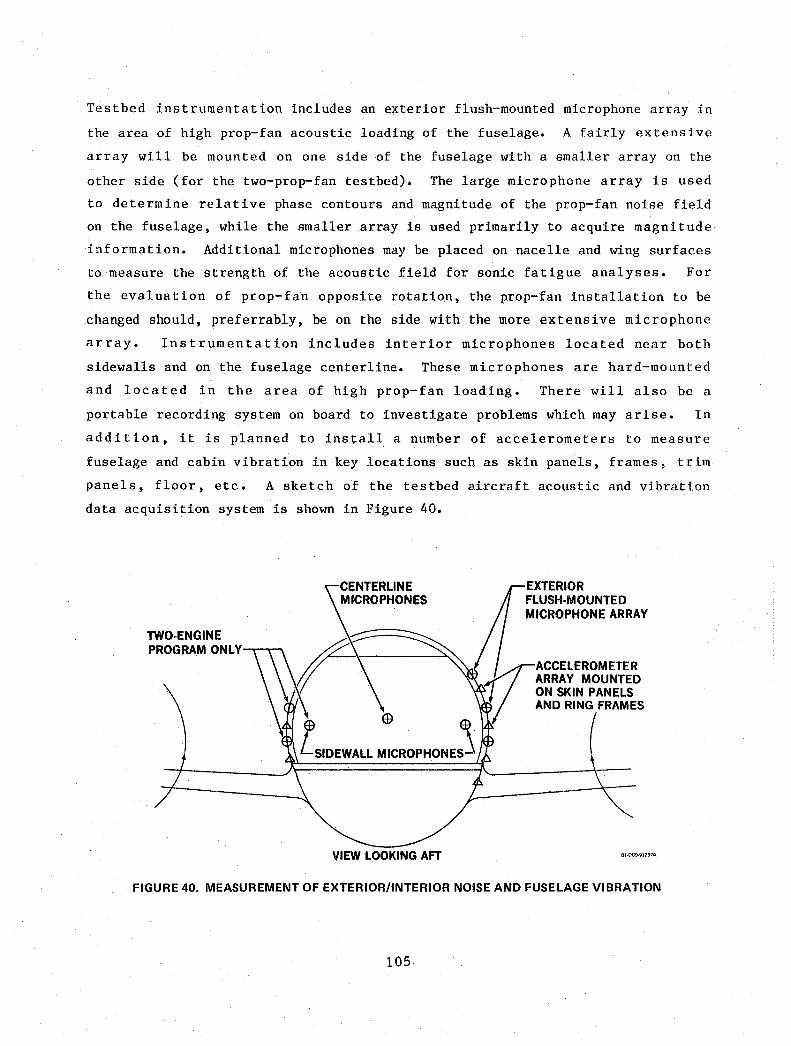
Testbed instrumentation includes an exterior flush-mounted microphone array in
the area of high prop-fan acoustic loading of the fuselage. A fairly extensive
array will be mounted on one side of the fuselage with a smaller array on the
other side (for the two-prop-fan testbed). The large microphone array is used
to determine relative phase contours and magnitude of the prop-fan noise field
on the fuselage, while the smaller array is used primarily to acquire magnitude
information. Additional microphones may be placed on nacelle and wing surfaces
to measure the strength of the acoustic field for sonic fatigue analyses. For
the evaluation of prop-fan opposite rotation, the prop-fan installation to be
changed should, preferrably, be on the side with the more extensive microphone
array. Instrumentation includes interior microphones located near both
sidewalls and on the fuselage centerline. These microphones are hard-mounted
and located in the area of high prop-fan loading. There will also be a
portable recording system on board to investigate problems which may arise. In
addition, it is planned to install a number of accelerometers to measure
fuselage and cabin vibration in key locations such as skin panels, frames, trim
panels, floor, etc. A sketch of the testbed aircraft acoustic and vibration
data acquisition system is shown in Figure 40.
TWO·ENGINE PROGRAM ONLY--r-...........
CENTERLINE MICROPHONES
VIEW LOOKING AFT
EXTERIOR FLUSH·MOUNTED MICROPHONE ARRAY
ACCELEROM ETER ARRAY MOUNTED ON SKIN PANELS AND RING FRAMES
(
Bl·OC9·91237A
FIGURE 40. MEASUREMENT OF EXTERIOR/INTERIOR NOISE AND FUSElAGE VIBRATION
105

The testbed aircraft will have a representative passenger interior in the area
of prop-fan loading including seats, carpet, and interior panels. The data
recording equipment will be located away from this area, probably in the rear
of the aircraft. All necessary data reduction equipment and techniques are
available at the Douglas Long Beach facility as discussed in the flight test
portion of this report, Task VI.
106


TASK V
CONCEPTUAL DESIGN OF TESTBED SYSTEMS
The principal design changes to the basic DC-9 aircraft for the DC-9 prop-fan
testbed are encompassed in the integration of the prop-fan/engine/nacelle into
the basic DC-9 aircraft. With this propulsion system change, minor
modification to the fuel supply system, controls, and the installation of
necessary flight test instrumentation and recording equipment, the basic DC-9
may be converted to an appropriate prop-fan testbed airplane.
To properly orient the prop-fan/engine/nacelle on the aircraft wing, the
aircraft characteristics and propulsion system local onset flow field are
evaluataed. For the DC-9, the aircraft angle-of-attack as a function of lift
coefficient (CL) is shown in Figure 41. The aircraft angle-of-attack is
referenced to the fuselage reference plane. Using these data and the flow
field data similar to that shown in Figure 42, the excitation factors for
several fore and aft locations of the prop-fan are evaluated at critical flight
points. The results of this work provide the prop-fan orientation angles such
as are shown in Figure 13.
DC-9-10 DC-9-30 AND C9 1.2 1.2
1.0 1.0
0.8 0.75
0.8
ClTO 0.6 0.6
0.4 0.4
0.2 0.2
0 2 4 6 8 10 12 14 16 0 2 4 6 8 10 12 14 16 0{. FRP O<FRP
I I I I I I I I I I I 0 0.05 0.10 0.15 0.20 0.25 0 0.05 0.10 0.15 0.20 0.25
(RAD) FRP (RAD) FRP 8O·GEN·27422
FIGURE 41. DC-9 LIFT VARIATION WITH ANGLE OF ATTACK
107

FLOW PI!U) AH~ t;)F THe WING IN THE WING PlANIE .
;Vi)( 0.95
.v-;:~ .30. . ___ -TYPICAL'
=
,PRPP
0.90",!' "'---r---,..---..,---.., 0.,08, .' ~~! . I~f :10
,X -".SEMf.$I'N! ,0.06
. x • DISfANCll AHU\O 01' WING \.lADING EDGE
V • SPI\NWISl 0ISf FROM FUSELAGE 4-Z • VEIITICAL OIST FIIOM WING PLANE
A\.L VEI.OCITIES RliLATtVE TO FIIEE SffIEAM
80-0C-9-91S49-1A
FIGURE 42. DC-9 WING BODY FLOW FIELDS
The nacelle external lines for the finalized DC-9 flight testbed may be
contoured in such a manner as to minimize the local disturbances to the wing
flow. Analytical methods will be used to determine the local flow streamlines
and the nacelle will be accordingly shaped, within practical structural and
mechanical constraints, to these streamlines.
The final prop-fan/engine/nacelle installation on the wing, from the
aerodynamic point of view, will be evaluated by taking into account the
pressure distributions calculated for the proposed flight test geometry.
108

NACELLE AND WING STRUCTURAL INTEGRATION
The installation of a prop-fan on the wing of a DC-9 testbed aircraft is a
simple arrangement within minimum rework required to the existing structure.
The aircraft is to be refurbished, upon completion of the test program, to its
original configuration. The location of the prop-fan in relation to the wing
is critical, requiring a long nacelle which extends well forward of the wing
leading edge.
Previous turboprop installations have been mounted to a metal tube truss
arrangement as the propellers were generally a short distance forward of the
wing leading edge. These original structural arrangements utilizing tubular
members were not fail-safe due to a single strut configuration. Fixes
incorporated into this type of arrangement added weight to both the gearbox
mount and to the supporting nacelle structure. Consequently, with the long
nacelle necessary for the satisfactory prop-fan installation, consideration is
given to an integrated structural design. This has proven to be a feasible
arrangement.
Two different turboshaft engines, the Allison T701 and T56, are considered for
use as the power source for the prop-fans. Each utilizes the same gearbox with
some slight modifications.
Preliminary sketches of the T701 and the T56 engine installations on the
DC-9-10 wing are shown in Figures 43 and 44, respectively. The T701
arrangement is more compact and the nacelle size meets the preliminary
requirements for blockage limitations set forth by Hamilton Standard for an
approximate ten foot (3.05 m) diameter prop-fan.
The length of the nacelle supporting the T701 engine package is 169 inches
(429 cm), or 14.08 feet (4.29 m). This is measured from the wing quarter chord
to the prop-fan plane. The T56 installation is 179 inches (455 cm), or 14.91
feet (4.55 m), based on the same ground rules. Based on Hamilton Standard
data,(Reference 2) shown in Figure 45, the minimum length for the T701 nacelle
designed for Mcruise = .8, with the ten foot (3.05 m) diameter prop-fan, is 147
inches (373 cm or 12.2 feet (3.73 m).
109

10-FOOT (3.05m) DIA PROP· FAN
WINGCf4\
(429 cm)-----~ .. I
81·GEN·21825
FIGURE 43. INSTALLATION OF ALLISON T701 ENGINE AND PROP·FAN ASSEMBLY ON DC-9·10 AIRCRAFT WING
WING Cf4
'-:;:,_~~~~1_79_IN_' _(4-;-55_c_m)~~~ __ +"""-+-__ J~L.~
@ 8·FOOT (2.44m)DIA PROp· FAN
81·DC9·91256
FIGURE 44. INSTALLATION OF ALLISON T56 ENGINE AND PROP·FAN ASSEMBLY ON DC·9·10 AIRCRAFT WING
110

g5 ....
::J: I-
4 e,:, z w .... w .... .... w
3 0 < z :IE ::t :IE Z 2 i
LOADS FOR 6 BLADES:
17
E ::; 15 -~
M= 59,OOO¢1 D/16\3
V=885¢!D/16\2
"'~ I--
~ I
~ 13 e,:, z w
..........• ~ ;:: 11 :I w ~ 9 z :IE ::t 7 :IE Z i ~ v
tAn ",01 --r-Mn=0.6
10 12 14 16 18 PROp·FAN DIAMETER - D (FT)
PROP·FAN DIAMETER - D (m)
-LOADS FOR 8 AND 10 BLADES:
M=78,750¢ID/16\3
V=1180¢!D/16\2
~
DISIN FEET
M IS IN INCH·POUNDS
V IS IN POUNDS
Mn 0.6 0.7 0.8
¢ 3.6 33 2.9
20 '" t 9.5 DEG 7.8 DEG 63 DEG
WHERE:
6 Mn IS FREESTREAM MACH NO. eI> IS FIRST ORDER EXCITATION FACTOR 'I',IS NACELLE TILT ANGLE RELATIVE TO WING ZERO LIFT LINE 81 oe,,,,,,
FIGURE 45. MINIMUM PROP·FAN NACELLE LENGTH AND LOAD DATA (REF 2)
The minimum length of the T56 nacelle, with an 8 foot (2.44 m) prop-fan, is not
quoted on Figure 45. The T56 nacelle is longer than the T701 nacelle and is,
therefore, assumed to exceed the minimum length. The nacelle lengths are
determined by positioning the engines completely forward of the wing front
spar. This positioning allows easy access to, and removal of, the engine
without removing the nacelle.
The basic diameter of the nacelle for the T701 installation is 42 inches (107
cm) which corresponds to 35 percent of the 120 inches (305 cm) prop-fan
diameter. This is compatible with the Hamilton Standard recommendations as
noted on Figure 46.
111

NACELLE DIA PROP~FAN DIA
0.3 5 Vi 8 AND 10 jLADES
/ 0 ~ /
I 6BlADES-
I / I
5
0.3
0.2 I I
0 I I 0.2
I I I I o
o 10 20 30 40 50 60
SHP/D2 AT 35,000 FT (10,668 m)S. D. (DESIGN CASE)
o 100 200 300 400 500
KW/m 2 82-GEN-2825
FIGUBE 46. RECOMMENDED NACELLE/PROP·FAN DIAMETER RATIO
The T56 installation has the same gearbox; therefore, the nacelle can only be
reduced to a minimum of 38.5 inches (97.8 cm) diameter, thus the nacelle to
prop-fan diameter ratio becomes 40 percent which is in excess of the Hamilton
Standard recommendation.
Guidelines were established by Hamilton Standard for the design of the prop-fan
spinner and hub. The shape of the system is plotted in Figure 47. The T701
engine installation is able to conform to these lines. The T56 nacelle
requires a larger hub than the 35 percent recommended.
As noted in previous sections, the Allison T701 engine package is selected for
the DC-9-10 testbed installation. The structural configuration will be
described for this system in the following paragraphs.
112
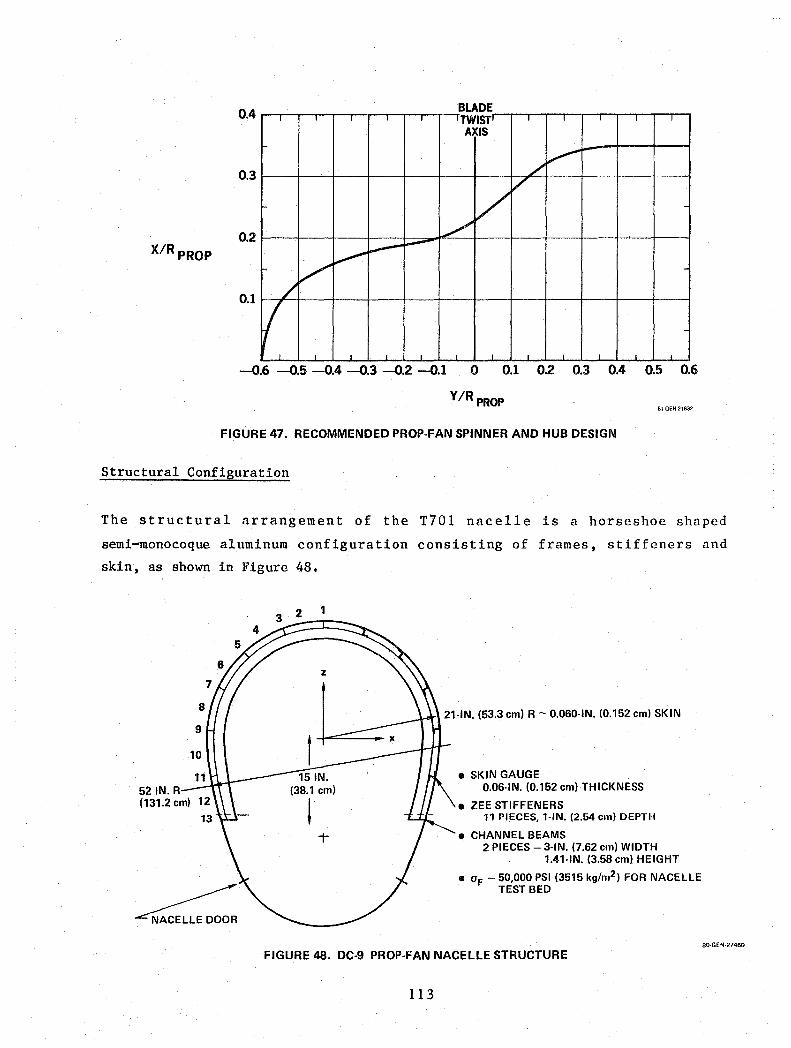
0.4 BLADE , , , , , 'TWIST' , , , , AXIS
0.1
./ ".,-
/ V
~ ~ ~
/' ~
/
(
0.3
0.2 X/R pROP
-0.6 -0.5 -0.4 -0.3 -0.2 -0.1 o 0.1 0.2 0.3 0.4 0.5 0.6
VIR PROP 81·GEN·21832
FIGURE 47. RECOMMENDED PROP·FAN SPINNER AND HUB DESIGN
Structural Configuration
The structural arrangement of the T701 nacelle is a horseshoe shaped
semi-monocoque aluminum configuration consisting of frames, stiffeners and
skin, as shown in Figure 48.
521N.R (131.2 em)
8
9
10
11
~ ...cNACELLE DOOR
1
21-IN. (53_3 em) R - 0.060-IN. (0.152 em) SKIN
• SKIN GAUGE 0.06-IN. (0.152 em) THICKNESS
• ZEE STIFFENERS 11 PIECES, 1-IN. (2.54 em) DEPTH
• CHANNEL BEAMS 2 PIECES - 3-IN. (7.62 em) WIDTH
1.41-IN. (3.58 em) HEIGHT
• OF - 50,000 PSI (3515 kg/m2) FOR NACELLE TEST BED
FIGURE 48. DC-9 PROP-FAN NACELLE STRUCTURE
113
80-GEN-27460

A modified T56 gearbox and a T701 engine are secured together as a single unit;
therefore, their structural support is at the gearbox centerline and the aft
mount of the engine. Fail-safe supports can be designed at each attach point
and the shell structure is a fail-safe member between them.
Access to the engine section is through an access door covering the entire
lower portion of the nacelle. The door opening is from the back face of the
gearbox to midway between the .,ing leading edge and front spar. The door is
hinged on the outboard side and when closed and latched will provide a torque
path for the balance of the structure. The door structure is an aluminum inner
and outer skin arrangement stiffened with aluminum ribs.
The engine and gearbox assembly is positioned at an angle to the centerline of
the nacelle, in the profile view, in order to provide adequate prop-fan ground
clearance and to keep the nacelle close to the wing upper surface. The engine
tail pipe is positioned so that any raw fuel from engine starts will drain aft,
away from wing structure.
Nacelle Attachment to Existing Wing Structure
Two aircraft have been considered for the flying testbed. They are the -10 and
-30 series of the DC-9 airplane. The two wing structural boxes are similar.
The -30 is more difficult to rework because of the leading edge slat system.
The proposed structural integration of the prop-fan nacelle is such that a
minimum of rework is necessary to the wing box. Two machined fittings are
mounted to the forward side of the front spar. Straps are installed on the
upper and lower skins to introduce the loads into the wing box.
Two machined fittings are attached on the aft side of the rear spar with straps
from the fittings to both skins. The forward set of attachments resist
vertical, thrust, and side loads. The aft set has vertical and side loads. A
pictorial view is shown in Figure 49.
114
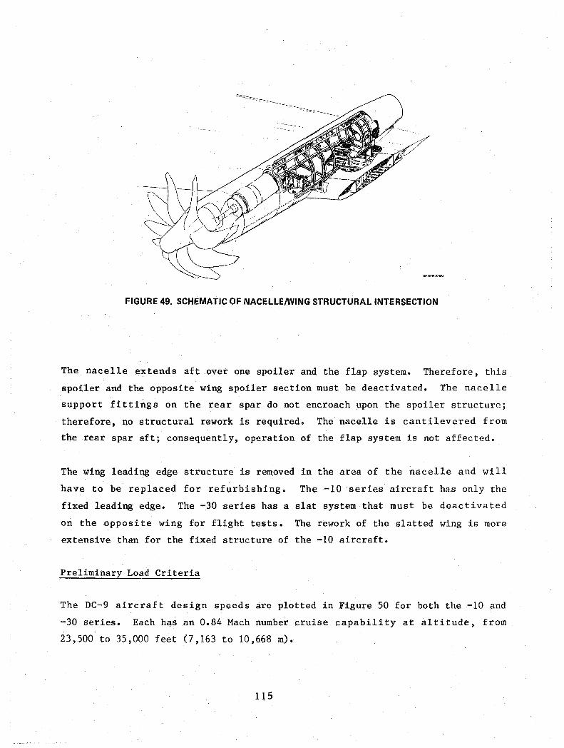
FIGURE 49. SCHEMATIC OF NACELLEIWING STRUCTURAL INTERSECTION
The nacelle extends aft over one spoiler and the flap system. Therefore, this
spoiler and the opposite wing spoiler section must be deactivated. The nacelle
support fittings on the rear spar do not encroach upon the spoiler structure;
therefore, no structural rework is required. The nacelle is cantilevered from
the rear spar aft; consequently, operation of the flap system is not affected.
The wing leading edge structure is removed in the area of the nacelle and will
have to be replaced for refurbishing. The -10 series aircraft has only the
fixed leading edge. The -30 series has a slat system that must be deactivated
on the opposite wing for flight tests. The rework of the slatted wing is more
extensive than for the fixed structure of the -10 aircraft.
Preliminary Load Criteria
The DC-9 aircraft design speeds are plotted in Figure 50 for both the -10 and
-30 series. Each has an 0.84 Mach number cruise capability at altitude, from
23,500 to 35,000 feet (7,163 to 10,668 m).
115

(12)
E (8)
§ w o :> .... 5 « (4)
o
40r------------------------,
.... Ll..
35
30
8 25 o -w g 20 .... 5 « 15
10
5
DC-9-10
0 ..... --'---'-.................... _ ............. _ ...... -'-' 120 160 200 240 280 320 360 400 440
AIRSPEED (KNOTS) EAS I I I I I I
300 400 500 600 700 800
(km/HR)
(12)
E (8) o 8 -w o :> .... 5 « (4)
o
40~----------------------~
35
30
;:: ~ 25
~ ; 20 o :>
~ 15 ..J «
10
5
MTOGW = 108,000 LB (48,526 kg)
DC-9-30
O~~ __ _'_ __ L-~~~~ __ ~~
120 160 200 240 280 320 360 400 440
AIRSPEED (KEAS) I I I I I I
300 400 500 600 700 800
(km/HR) BO-G EN-2745 7 A
FIGURE 50. AIRCRAFT DESIGN SPEEDS
The prop-fan/gearbox system strength will be assumed to be safe life, thus
precluding fail-safe design for any remote possibility of a seizure of the
rotating elements. However, engine seizure of the gas generator, resulting in
decoupling between itself and the gearbox, will be considered. Spool-down time
will be one (1) second for any single spool seizure. The spool-down time for
any two spool seizures will be two (2) seconds.
criteria.
This follows DC-10 fan jet
Structural integrity involves safe flight throughout the expected flight regime
for the prop-fan testbed. Structural placards related to possible restrictions
such as gross weight, maneuvers, placard speeds and touchdown sink rate will be
determined in the design phase.
116

The loads used to define the preliminary structural member sizes are based on
typical wing mounted nacelle load factors from the DC-10 criteria. The noted
load factors and thrust loads are listed in Figure 51. The preliminary
analysis gives values for wing-to-nacelle attach loads that can be tolerated by
this structural arrangement without a major wing rework program. The loads are
noted in Figure 52. The final nacelle-wing attach loads will be determined in
the testbed design phase.
OESIGNCONOITIONS: AABltRARVUlllMATE lOADS
INERTIAL LOAD FACTORS
FN MXWN CONDITION q. q, q. K 10. 3 It 10.6
10 CONDITION DESCRIPTION " " LB IN -l8 FORCE ANO MOMENT AXIS SYSTEM
-,
1'1)( 1+ OUTBOARO)
,/ MXWN (PITCH)
(+45,278)
(-25,873)
501 19 OOWN AND THRUST -7.0
502 79 DOWN, 3.259 AFT, 1.7590B, 1.15 3.25 -7.0 PITCH DOWN MOMENT
f1, (+UP)
503 79 DOWN, 3.259 AFT, 1.00g IB, -1.0 3.25 -7.0 PITCH DOWN MOMENT
e,G, 50. 4g UP, 1.89 FWD. 1.75g0B, 1.15 -l.B '.0 PITCH UP AND THRUST
505 4g UP, 1.8g FWD, 1.DOg 19, -1.0 -1.8 4 .• PITCH UP AND THRUST
1'1y I+Af:T1
fM .... (YAWl
6 .. 6.164g DOWN, 49 AFT. 0.12 '.0 -6.164 PITCH DOWN MOMENT
507 3g INBOARD, 1.59 DOWN -3.0 -1,5
6 .. 3g OUTBOARD, 1.~ DOWN 3 .• -1.5
50. 2.72g OUTBOARD, 1.56 DOWN, 2.72 -1.07 -1.56 PITCH DOWN AND YAW 08 MOMENTS
610 MAX. VAWMOMENT AND -1.5 1.6g DOWN
511 LIMIT THRUST )( 2.25 1.
512 MAX. REVERSE THRUST AND -1.5 1.5g00WN
513 MAX, SEIZURE TORQUE AND -1.5 1.5gDOWN
FIGURE 51. NACELLE STRUCTURAL LOADS
FOR 7g ON:
FOR 4gUP:
DESIGN NORMAL LOAD FACTORS
V F = 90,556 LB (COMPRESSION) (402,974 N)
VA = -55,556 LB (TENSION) (247,224 N)
VF = -51,746 LB (TENSION) (230,270 N)
VA = 31,746 LB (COMPRESSION) (141,270 N)
AFT FRAME
FOR ± 3g SIDE
SF = ±38,809 LB (172,720 N)
SA = +23,809 LB (105,950 N)
....... (±19,404) (36,348 N) (±11,904) (52,973N)
DOWN (-27,778) LOAD (+45,278) (201,487 N) (-27,778) (123,612 N)
79
(-25,873) (115,135 N) (+15,873) (70,635 N) UP
(+15,873) LOAD 4g
fiGURE 52. NACELLE/WING fRAME SUPPORT LOADS
117
MVWN MzWN
K 10.8 1(10"6 IN·lB IN-LB
8O·GEN·27418
80·GEN·27454A
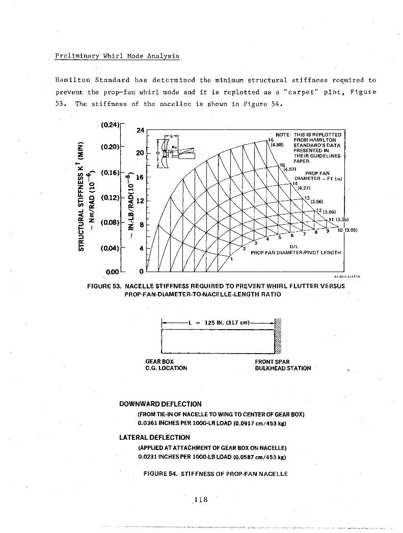
Preliminary Whirl Mode Analysis
Hamilton Standard has determined the minimum structural stiffness required to
prevent the prop-fan whirl mode and it is replotted as a "carpet" plot, Figure
53. The stiffness of the nacellee is shown in Figure 54.
(0.24)
-2!: (0.20) :it -... ~ - (0.16) ~1 LLI 0 Z .... L&. -L&. c (0.12) ~ II(
0:: ...I ........ II( E 0:: z (0.08) ::> t> 1
::> 0:: Ii; (0.04)
0.00
24
20 1Fb -'1' 16 0 .... -~ 12 0:: ........ m ...I
I.
8 ~
4
0,
NOTE: THIS IS REPLOTTED 16 FROM HAMILTON
(4.88) ST ANDARD'S DATA
15
PRESENTED IN THEIR GUIDELINES PAPER .
(4.57) PROp· FAN
DIAMETER - FT (m) 14
(4.27)
6
D/L PROP· FAN DIAMETER/PIVOT LENGTH
81-DC9·91241B
FIGURE 53. NACELLE STIFFNESS REQUIRED TO PREVENT WHIRL FLUTTER VERSUS PROP-FAN-DIAMETER-TO-NACE LLE-lENGTH RA no
It-,"--L = l251N. (317 cm)----I"I
GEARBOX C.G. LOCATION
DOWNWARD DEFLECTION
FRONT SPAR BULKHEAD STATION
(FROM TIE-IN OF NACELLE TO WING TO CENTER OF GEAR BOX)
O.036lINCHES PER lOOO-LB LOAD (0.0917 cm/453 kg)
LATERAL DEFLECTION
(APPLIED AT ATTACHMENT OF GEAR BOX ON NACELLE)
0.0231 INCHES PER 1000-LB LOAD (0.0587 cm/453 kg)
FIGURE 54. STIFFNESS OF PROP-FAN NACelLE
118

Definition of terminology shown in the preceding Figures 51 and 52 is as
follows:
L
D
minimum effective tors5.onal stiffness of wing/nacelle
mount system (pitching)
distance from the wing C/4 station to the prop-fan plan
of rotation
prop-fan diameter
A preliminary flutter/whirl mode analysis is performed to determine the
feasibility of installing the prop-fan assembly as far forward of the wing as
required with the stiffened monocoque structure as developed. This analysis is
performed using the Allison T701 engine with a 10 foot (3.05 m) diameter 10
blade prop-fan with a tip speed of 800 feet per second (244 m/sec).
The results are shown in Figure 55. The total installation is predicted to be
flutter-free and stable in a whirl mode up to 1.2 VD (475 KEAS) [475 km/kg] of
the DC-9 airplane. These conceptual analyses will be expanded prior to design
release.
ENGIN~ YAW FREQUENCY
(Hz)
7r----------,.----------.
6
5
4
3
2
1
'MINIMUM EXPECTED DESIGN VALUES
STABLE ZONE
WHIRL ZONE UNSTABLE
DIVERGENCE ZONE
01234567 ENGINE PITCH FREQUENCY (Hz)
FIGURE 55. WHIRL FLUTTER BOUNDARY
Prop-fan Excitation Factors
Hamilton Standard performed several analyses to determine the effect on
prop-fan excitation factors of length of nacelle, wing sweep, and direction of
rotation near the fuselage for the DC-9-10 aircraft. The lowest factors for
the T701 and T56 installations occurred for a prop-fan rotation where the tips
rotate up near the fuselage (up inboard).
119

The effect of prop-fan rotation on excitation factors are compared to design
values formulated by Hamilton Standard and are presented in Figure 56. As
shown in Figure 56, the excitation factors are lower for the up-inboard
rotation case. The prop-fan excitation factors are calculated for the T701
engine installation on both the -10 and -30 series of the DC-9. The results
are compared to each other and to the established design values shown on Figure
57. For this comparison the prop-fan rotation considered in this figure is
down-inboard. The series -30 arrangement has the lowest calculated values for
the excitation factor.
HAMSTD PROP-FAN ROTATION DESIGN
VALUE
TURBOSHAFT ENGINE
EQUIVALENT DES 1P EF 4.5 BASIC IPONLV 3.3
r 1.0
~ 2P 0.375 !:i 3P 0.111 ..J ~ 4P 0.048
5P 0.024
DC·9·lO PROP. FAN DIAMETER 9.5 FT (2.90 m) T-701
8.1 FT (2.47 m) T-56
NACELLE DOWNTILT - 4.3 DEG (0.075 rad) PROP PLANE DISTANCE TO WING Cf4 = 14.08 FT (4.29 m) MAXIMUM WEIGHT CLIMB
UP INBOARD DOWN INBOARD
T-56 T-701 T-56
3.670 4.753 4.617
3.255 3.329 3.253 1.0 1.0 1.0 0.058 0.312 0.308 0.052 0.085 0.082 0.010 0.023 0.023 0.002 0.007 0.006
80·GEN·27452A
FIGURE 56. EFFECT OFDIRECTION OF PROP·FAN ROTATION AND EXCITATION FACTORS (EF) OF
PROP·FAN INSTALLATION
MAXIMUM WEIGHT CLIMB PROP-FAN DIAMETER - 9.5 FT (2.90 m) PROP-FAN ROTATION - DOWN INBOARD
HS DC-9-l0 DC-9-30 DESIGN VALUES T-701 T-701
EQUIVALENT DES 1P EF 4.5 4.753 2.940
BASIC IPONLV 3.3 3.329 2.736
r 1.0 1.0 1.0
~ 2P 0.375 0.312 0.072
5 3P 0.111 0.085 0.004
UJ 4P 0.048 0.023 0.008 0::
5P 0.024 0.007 0.003
80·GEN·27453 A
FIGURE 57. DC-9-10 AND DC-9-30 PROP-FAN EXCITATION FACTORS
120

Sensitivity of the prop-fan excitation factor to nacelle installation geometry
is calculated for the T701 engine on the DC-9-30 airplane. Parametric
variation of down tilt angle and nacelle length (Figures 56 through 58) are
considered. The down tilt angle refers to the orientation of the prop-fan
relative to the wing zero lift line such that the inflow to the prop-fan is at
or near zero degrees. The down tilt angle for the prop-fan is varied from
o degrees to -6 degrees (.105 radians). The 6 degree (.105 radians) down tilt
position has the smallest excitation factor. As can be seen from Figure 58,
the shorter nacelle length, 9.0 feet (2.74 m), results in considerably higher
excitation factors over those associated with the basic design length of 14.08
feet (4.29 m).
EQUIVALENT DES IP EF BASIC IPONLY
~ 2P ... 3P
[
lP
~ 4P 0:::
5P
* (REfERENCE CASE)
DC-9-30
T·701 TURBOSHAFT ENGINE
MAXIMUM WEIGHT CLIMB
PROP PLANE TO Cf4 = 14.08 fT (4.29 m), DOWNTILT = 4.3 DEGREES (0.075*rad)
PROp·fAN ROTATION - DOWN INBOARD
NACELLE
BASIC LENGTH DOWNTILT DOWNTILT DOWNTILT
CONDITION = 9.0FT =6DEG =2DEG =ODEG (2.74 m) (0.105 rad) (0.035 rad)
2.940 4.682 2.139 4.0811 5.130 2.736 3.619 2.031 3.682 4.500 1.0 1.0 1.0 1.0 1.0 0.072 0.135 0.044 0.108 0.138 0.004 0.043 0.007 0.002 0.004 0.008 0.005 0.010 0.006 0.005 0.003 0.0009 0.004 0.003 0.002
8().GEN·274!50A
FIGURE 58. SENSITIVITY OF PROP·FAN EXCITATION FACTOR TO NACELLE INSTALLATION GEOMETRY
121

Alternate Testbed Structural Arrangement
The basic installation of the prop-fan nacelle on the wing is shown in Figure
43. The excitation factor is influenced by the nacelle length as measured from
the wing quarter chord and by the angle the prop-fan plane makes with the wing
zero lift line. Therefore, a proposed testbed structural arrangement to
determine flight test data for various nacelle lengths and prop-plane tilts is
developed during this phase of the study. A schematic is shown in Figure 59.
NACELLE/SUPPORT DIVIDING PLANE
(. j ~ ) V
(t~r/- ","'NO - ~ OVERLAP
~PIVOT ~ljl .. - 'I
i
~1-'=~ A-A TYPICAL FRAME
. (4 PLACES)
A..J ADJUSTMENT FOR NACELLE TILT - 0 TO 3 DEG (0,052 rad) (NOSE DOWN)
------- - ..-----------80-GEN-27514
FIGURE 59. PROPOSED NACELLE TESTBED ARRANGEMENT FOR VARIOUS PROP LOCATIONS AND TILT RELATIVE TO THE WING
The nacelle is attached to a mounting plate with eight tension bolts. There
are three additional nacelle frames each at the wing front and rear spar
attachment locations. Thus the nacelle may be moved as much as 30 inches (76.2
em) aft from the initial installation. The lower access door has three 10 inch
(25.4 em) long segments that may be removed separately as needed when moving
the nacelle aft.
The mounting plate is arranged such that it may be tilted nose down by pivoting
at the wing front spar location. The wing rear spar connection controls the
amount of tilt. The simple mechanical adjustment could be made on the ground.
122

PREFERRED NACELLE/WING INSTALLATION
Preliminary layouts and conceptual analyses have shown the feasibility of
installing a semi-monocoque structure nacelle, by means of four-point
attachment, to a DC-9 wing for flight testing. The resulting structural
stiffness is adequate to prevent whirl flutter. Provision is made for easy
engine removal. Rework of the wing box structure is minimized as an aid to
refurbishment after the test program. Summary of the advantages of this
engine/prop-fan structural mounting concept is given in Figure 60.
SIMPLE, STRAIGHTFORWARD MOUNT
STIFF MOUNT EFFECTIVE IN FLUTTER AND/OR WHIRL FLUTTER REDUCTION
EASE OF MAINTENANCE
• ENGINE REMOVAL FREE OF WING INTERFERENCE
• ACCESS TO NACELLE
• MODULAR ENGINE/PROP· FAN/GEAR BOX/ACCESSORY MAINTENANCE
FIGURE 60. ENGINE/PROP·FAN STRUCTURAL MOUNTING CONCEPT ADVANTAGES
It is recommended that a testbed article should be built and flown utilizing
the alternate configuration to obtain data for the various nacelle lengths and
tilts possible. Consideration should be given to the possibility of changing
the til t during flight since various stages of a flight mission profile could
impose large excitation factors when the prop-fan is not aligned correctly with
the wing flow field.
123

PROP-FAN CONFIGURATION WEIGHTS
Three testbed prop-fan propulsion system installation concepts are evaluated
utilizing DC-9-10 weights and geometry (shown in Table 4) as the baseline
airplane. The three wing-mounted prop-fan propulsion systems considered are
one Allison T701 turboshaft engine, one Allison T56 turboshaft engine, and the
two Allison T701 turboshaft engines shown in Figures 11, 12, and 13,
respectively.
One T701 Prop-fan Configuration
A group weight summary of the one engine T701 prop-fan installation, Figure 11,
is presented in Table 5. Description of the component systems follows.
The wing geometry and weight is like the DC-9-10 aircraft, except for a minimal
rework which is required for the integration of the prop-fan nacelle to the
wing. The rework includes the installation of four attach points (two fittings
located forward of the front spar and two fittings located aft of the rear
spar). The wing weight includes a weight penalty for the eight local straps,
located on the upper and lower skin panel and at each attach point, which
distribute the prop-fan installation loads into the wing box structure.
The horizontal and vertical stabilizer, fuselage, landing gear design and
weights are identical to the DC-9-10 airplane.
The flight control system weight is identical to the DC-9-10. The inboard
spoiler panel and actuation mechanism on both sides of the wing is deactivated.
The weight penalty required to deactivate the mechanism is negligible.
The turbofan nacelle, pylon, engine, and engine system weight of the basic
prop-fan testbed airplane is identical to the DC-9-10 aircraft.
The fuel system weight is increased over the base DC-9-10 weight to reflect the
additional plumbing required to supply fuel from the existing DC-9 fuel system
to the prop-fan engine.
124

TABLE 4
WEIGHTS AND GEOMETRY
BASELINE DC-9-l0 AIRCRAFT
English Units Metric Units
Maximum Ramp Gross Weight
Maximum Takeoff Gross Weight
Maximum Landing Gross Weight
Maximum Zero Fuel Gross Weight
Operational Empty Weight
Manufacturer's Empty Weight
87,100 lb 39,501 Kg
Trapezoidal Wing Area (Planform Area)
Theoretical Horizontal Tail Area
Theoretical Vertical Tail Area
86,300
81,700
71 ,800
50,213*
47,602*
834
276
161
ft 2
ft 2
ft 2
39,138
37,052
32,562
22,772
21,588
77 .5 m
35.65 m
14.96 m
Total Fuselage Length 1,105 in 28.07 m
Total Number of Passengers
(12) First Class
(60) Tourist
Two (2) Aft Fuselage Side-Mounted JT8D-7
72
** * Derived from Air Canada DC-9-l4 (DTS 3506) and averaged actual MEW of
six aircraft at time of original delivery.
** Air Canada Series 14 (Series 10 Standard airplane plus Specification
Change Notices) defined in Detailed Type Specification 3506.
125
2
2
2
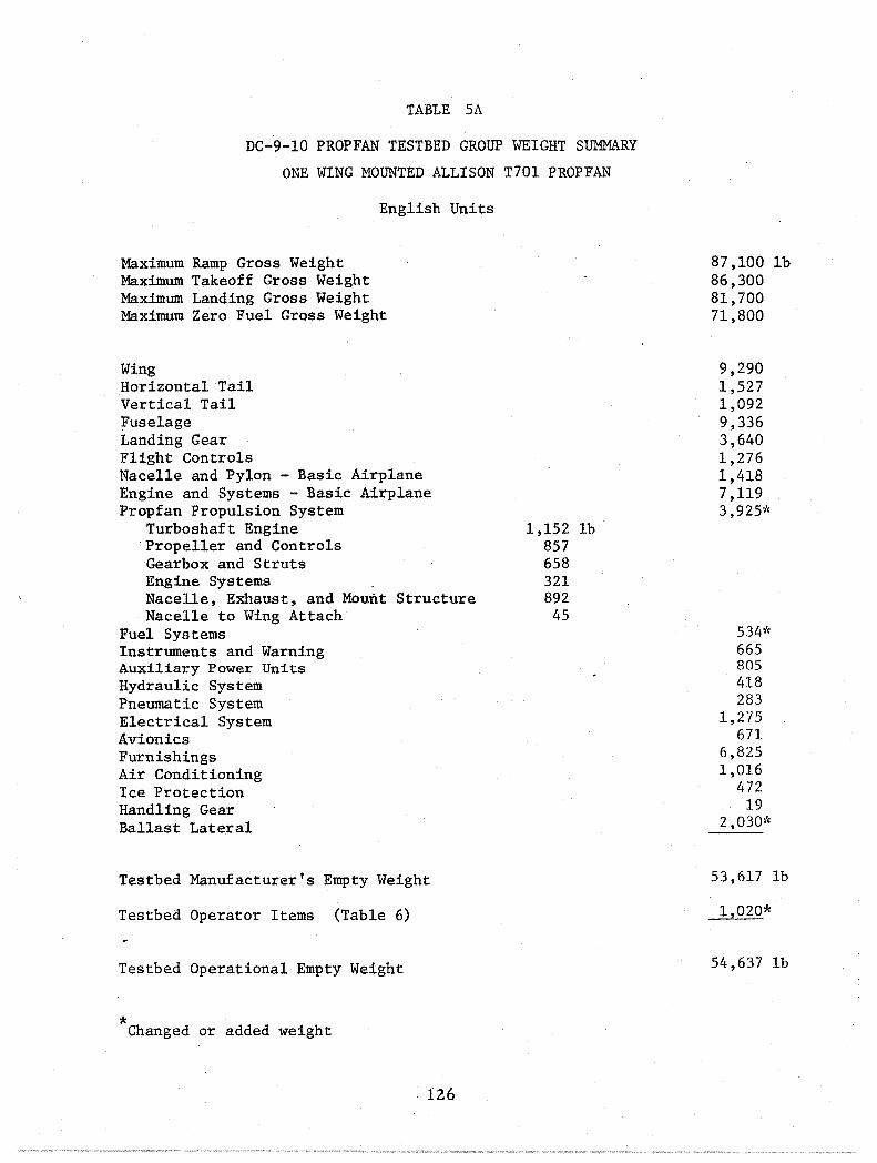
TABLE 5A
DC-9-l0 PROPFAN TESTBED GROUP WEIGHT SUMMARY
ONE WING MOUNTED ALLISON T70l PROPFAN
English Units
Maximum Ramp Gross Weight Maximum Takeoff Gross Weight Maximum Landing Gross Weight Maximum Zero Fuel Gross Weight
Wing Horizontal Tail Vertical Tail Fuselage Landing Gear Flight Controls Nacelle and Pylon - Basic Airplane Engine and Systems - Basic Airplane Propfan Propulsion System
Turboshaft Engine Propeller and Controls Gearbox and Struts Engine Systems . Nacelle, Exhaust, and Mount Structure Nacelle to Wing Attach
Fuel Systems Instruments and Warning Auxiliary Power Units Hydraulic System Pneumatic System Electrical System Avionics Furnishings Air Conditioning Ice Protection Handling Gear Ballast Lateral
Testbed Manufacturer's Empty Weight
Testbed Operator Items (Table 6)
Testbed Operational Empty Weight
* Changed or added weight
126
1,152 1b 857 658 321 892
45
87,1001b 86,300 81,700 71 ,800
9,290 1,527 1,092 9,336 3,640 1,276 1,418 7,119 3,925''(
534* 665 805 418 283
1,275 671
6,825 1,016
472 19
2,030*
53,617 1b
1,020*
54,637 1b

TABLE 5B
DC-9-10 PROPFAN TESTBED GROUP WEIGHT SUMMARY
ONE WING MOUNTED ALLISON T701 PROPFAN
Metric Units
Maximum Ramp Gross Weight Maximum Takeoff Gross Weight Maximum Landing Gross Weight Maximum Zero Fuel Gross Weight
Wing Horizontal Tail Vertical Tail Fuselage Landing Gear Flight Controls Nacelle and Pylon - Basic Airplane Engine and Systems - Basic Airplane Propfan Propulsion System
Turboshaft Engine Propeller and Controls Gearbox and Struts Engine Systems . Nacelle, Exhaust, and Mount Structure Nacelle to Wing Attach
Fuel Systems Instruments and Warning Auxiliary Power Units Hydraulic System Pneumatic System Electrical System Avionics Furnishings Air Conditioning Ice Protection Handling Gear Ballast Lateral
Testbed Manufacturer's Empty Weight
Testbed Operator Items (Table 6 )
Testbed Operational Empty Weight
* Changed or added weight
127
522 Kg 389 298 146 405
20
39,501 Kg 39,138 37,052 32,562
4,204 692 495
4,23Lf
1,650 574 643
3,228 1,780*
242 302 365 190 128 578 304
3,095 461 214
9 921*
24,316 Kg
463*
24,779 Kg

The prop-fan propulsion system weight includes a T701 turboshaft engine, a 10
blade Hamilton Standard prop-fan and prop-fan controls, a modified T56 gearbox,
engine related systems, nacelle and mounting structure, and nacelle to wing
attach structure. The T701 engine weight is based on information dated August
1980 from Detro.it Diesel Allison. The prop-fan weight represents a 10 blade,
9.5 foot (2.90 m) diameter, 800 feet per second (244 m/sec) tip speed, Hamilton
Standard prop-fan. The prop-fan weight is based on Hamilton Standard's weight
estimate which accounts for non-production processing methods and the use of
current technology. The .gearbox is a modified T56 gearbox; the modification
provides compatibility between the T701 engine, prop-fan, and T56 gearbox. The
gearbox weight is based on information from Allison and includes the gearbox,
shaft, struts, and oil. The prop-fan engine-related systems weight is based on
the P-3A Allison T56-A-IO systems weight which includes the lubrication system
(oil tank installation, cooling system, ducting, and plumbing), engine
controls, fire warning and extinguishing system, and the start system.
The nacelle structure weight is based on a preliminary design layout shown in
Figure 43. The metal fabricated upper nacelle structure is a semi-monocoque
design, constructed from skins, zee stiffeners, intermediate frames, engine and
nacelle mounts and frames, machined bulkheads, shear clips, lower keel beam
members, and attachments. The lower access door panel installation weights
include skins, doublers, frames, latching, and hinges. The weights for the
upper nacelle structure and lower access doors are estimated from preliminary
structural member sizing calculations. The engine air inlet installation
weight is based on preliminary estimates and includes skins, frames, intake
duct, lip assembly, seals, and attachments. The engine exhaust tailpipe and
aft fairing installation weights are based on statistical data of similar
designs. The weight includes the inner tailpipe installation, which starts at
the turbine rear flange and terminates at the exhaust nozzle plane, and the aft
outer fairing installations, which begins at the rear spar plane and ends at
the exhaust nozzle plane. The nacelle weight also includes the lower nacelle
to wing fairing and a titanium fireshie1d located between the wing leading edge
and the rear spar. The nacelle to wing attach structure weight is based on
preliminary estimates and does account for the attach structure and attachments
128

required to secure the prop-fan installation to the four attach points located
on the wing. The group weights for the instruments and warning system,
auxiliary power unit, hydraulic system, electrical system, avionics, air
conditioning system, ice protection system, and handling gear are identical to
the base DC-9-10 weights.
The furnishings group weight is also identical to the base DC-9-10 which
includes seats and passenger accommodations for twelve (12) first class
passengers and sixty (60) coach passengers. The production DC-9-10 cabin
sidewall panels and acoustic treatment, shown in Figure 33, are used for the
baseline testbed weight. The weight penalties associated with the various
acoustic treatments required for the acoustic test are assumed part of the
payload weight.
The base DC-9-10 pneumatic system weight is increased to reflect additional
ducting, valves, and controls necessary to supply bleed air to start the
prop-fan engine. The weight penalty for the modification is based on
preliminary estimates.
The lateral imbalance caused by the single prop-fan installation on one side of
the wing is corrected by installing ballast on the opposite side of the wing;
thus the testbed airplane lateral flying qualities are made similar to the
basic DC-9. Lead weights are installed in the wing between the front and rear
spar at the most practical outboard spanwise location.
The operator items weight for the testbed airplane is based on the ACA (DTS
3506) DC-9-14 weights and modified to represent weight consisting of items most
likely to be considered in a testbed program. The modification includes the
removal of two cabin crew members and their baggage, food, liquids, commissary
equipment, cabin supplies, galley inserts, and twenty gallons of potable water.
The remaining weight, with the addition of the prop-fan engine oil and unusable
fuel weight is shown in Table 6.
129
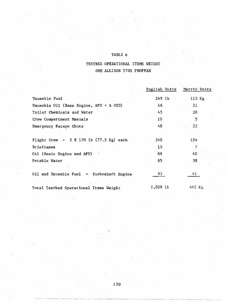
TABLE 6
TESTBED OPERATIONAL ITEMS WEIGHT
ONE ALLISON T70l PROPFAN
Unusable Fuel
Unusable Oil (Base Engine, APU < & CSD)
Toilet Chemicals and Water
Crew Compartment Manuals
Emergency Escape Chute
Flight Crew - 2 @ 170 lb (77.5 Kg) each
Briefcases
Oil (Basic Engine and APU)
Potable Water
Oil and Unusable Fuel - Turboshaft Engine
Total Testbed Operational Items Weight
130
English Units
249 lb
46
45
10
48
340
15
89
85
93
1,020 Ib
Metric Units
113 Kg
21
20
5
22
154
7
40
39
42
462 Kg

The balance diagram, shown in Figure 61, represents the loading features of the
base DC-9-10 airplane. The operational empty weight center-of-gravity (e.g.)
of the one engine prop-fan configuration and the two engine prop-fan
configuration are superimposed over the DC-9-10 to show that all of the
prop-fan configurations are within the DC-9-10 e.g. limits. The test equipment
(payload) should be placed in the forward section of the passenger cabin to
insure that the airplane e.g. is always forward of the aft balance limit.
PERCENT MAC to 15 20 25 30 35 40 45 DATE: 10/07/80
12
(5) 11
10
(4) 9
~ iii "'"
I .... 8
8. 7
12 FIRST CLASS AND 80 ECONOMY CLASS / / / / PASSENGERS AT 165 POUNDS ~ACH J
\ \ / I / / V \ 1\ / I / V / MTW
\ \I MTOW .......... II / / / \
MLW
/ / IJ TESTBEDJ{W MtFW /
50
g !i: (3) l- \ , ORW~R:DI--~bcl«OOB~ t. 2 JROP.FANS t!) :x iii t!) 8 5: iii
5: 5
" CARGO BAY
1\ ~ t:J3fL / (2)
4
3
(1)
\ 0jw1/o/ '-1,PROP-FAN
• (LB) - INCLUDING PASSENGER ~EW
BAGGAGE I Ii' ~ II 1/ • MAX LOAD ASSUMES OTHER BAYS ARE I-FULL -+--+- I I I • MIN LOAD ASSUMES OTHER BAYS ARE
\ /; ~t / EMPTY I III I 2 -40 -35 -30 -25 -20 -15 -10 -5 0 5 10 15 20 25 30 35 40 45
MOMENT -100,000 IN_-LB , I I I , I I I I I , , I I I , , I I , I ,
(-5011-4511-4O)1(-35H-30)~-2511(-20M(-1511(-10) (--5) (5) (10) (15) (20) (25) (30) (35) (40) (45) (50) (55)
ENGLISH UNITS (cm-kg x 105) MAX TAXI WEIGHT (MTW) (LS): MAX TAKEOFF WEIGHT (MTOW) (LS): MAX LANDING WEIGHT (MLW) (LS): MAX ZERO FUEL WEIGHT (MZFW) (LS): OPERATORS EMPTY WEIGHT (OEW) (LS):
METRIC UNITS MAX TAXI WEIGHT (MTW) (kg) MAX TAKEOFF WEIGHT (MTOW) (kg): MAX LANDING WEIGHT (MLW) (kg) MAX ZERO FUEL WEIGHT (MZFW) (kg): OPERATORS EMPTY WEIGHT (OEW) (kg):
97100 86300 81720 71800 58213
44036 39138 37061 32562 26400
INTERIOR ARRANGEMENT PER OWS 5900540
MEAN AERODYNAMIC CHORD (MAC) (IN.): 141.500 LEADING EDGE MAC (5TH): 543.130 QUARTER CHORD (C/4) (STA): ' 580.000 REFERENCE STATION (STA): 580.000 DEW CENTER OF GRAVITY (STA): 502.800
MEAN AERODYNAMIC CHORD (MAC) (m): 359.4 1379 1473 1473 1277
LEADING EDGE MAC (5TH) QUARTER CHORD (C/4) (STA): REFERENCE STATION (STA): DEW CENTER OF GRAVITY (STA):
80~GEN·27458B
FIGURE 61. DC-S·10 CG DIAGRAM
131

Two T701 Prop-fan Configuration
A group weight summary of the two engine T701 prop-fan DC-9-10 configuration
(Figure 13) is shown in Table 7.
The wing weight is similar to the one engine prop-fan configuration shown in
Table 5, except the rework weight penalty for the integration of the prop-fan
nacelles to the wing is twice as much as the one engine prop-fan configuration.
The horizontal stabilizer, vertical stabilizer, fuselage, landing gear, flight
control system, and the basic airplane nacelle, pylon, engine, and engine
system weights are identical to the one engine prop-fan configuration.
The fuel system weight is like the one engine prop-fan fuel system weight,
except the prop-fan engine fuel supply plumbing weight penalty is twice as much.
The two engine prop-fan propulsion system consists of two Allison T701 prop-fan
installations (one on each side of the fuselage). The geometry is like the one
engine T701 prop-fan installation with the engine, propeller and controls,
engine systems, nacelle, engine mounting structure, and nacelle to wing attach
structure. The total propulsion system weight is twice as heavy as the one
engine prop-fan installation. A weight penalty is added to one modified T56
gearbox to reflect an idler gear and housing installation required for the
opposite rotation prop-fan.
The group weights for the instruments, auxiliary power unit, hydraulic system,
electrical system, avionics, furnishings group, air conditioning group, ice
protection group, and handling gear are identical to the one engine prop-fan
configuration.
The pneumatic system weight is like that of the one engine T701 prop-fan
configuration, except the prop-fan engine start system ducting, valve, and
control weight penalty is twice as heavy as the one engine prop-fan penalty.
132

TABLE 7A
DC-9-l0 PROPFAN TESTBED GROUP WEIGHT SUMMARY
TWO WING MOUNTED ALLISON T701 PROPFAN
English Units
Maximum Ramp Gross Weight Maximum Takeoff Gross Weight Maximum Landing Gross Weight Maximum Zero Fuel Gross Weight
Wing Horizontal Tail Vertical Tail Fuselage Landing Gear Flight Controls Nacelle and Pylon - Basic Airplane Engine and Systems - Basic Airplane Propfan Propulsion System
Turboshaft Engine Propeller and Controls Gearbox and Struts Engine Systems Nacelle, Exhaust, and Mount Structure Nacelle to Wing Attach
Fuel Systems Instruments and Warning Auxiliary Power Units Hydraulic System Pneumatic System Electrical System Avionics Furnishings Air Conditioning Ice Protection Handling Gear Ballast Lateral
Testbed Manufacturer's Empty Weight
Testbed Operator Items (Table 8)
Testbed Operational Empty Weight
* Changed or added weight
133
2,304 1b 1,714 1,316
642 1,784
90
87,1001b 86,300 81,700 71,800
9,290 1,527 1,092 9,336 3,640 1,276 1,418 7,119 7,850*
554* 665 805 418 404*
1,275 671
6,826 1,016
472 19 o
55,572 1b
1,113*
56,685 1b
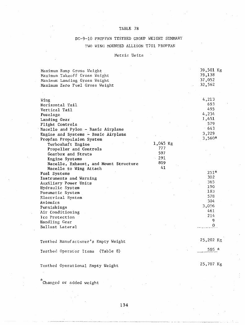
TABLE 7B
DC-9-l0 PROPFAN TESTBED GROUP WEIGHT SUMMARY
TWO WING MOUNTED ALLISON T70l PROPFAN
~1etric Units
Maximum Ramp Gross Height Maximum Takeoff Gross Weight Maximum Landing Gross Weight Maximum Zero Fuel Gross Weight
Wing Horizontal Tail Vertical Tail Fuselage Landing Gear Flight Controls Nacelle and Pylon - Basic Airplane Engine and Systems ~ Basic Airplane Propfan Propulsion System
Turboshaft Engine Propeller and Controls Gearbox and Struts Engine Systems Nacelle, Exhaust, and Mount Structure Nacelle to Wing Attach
Fuel Systems Instruments and Warning Auxiliary Power Units Hydraulic System Pneumatic System. Electrical System Avionics Furnishings Air Conditioning Ice Protection Handling Gear Ballast Lateral
Testbed Manufacturer's Empty Weight
Testbed Operator Items (Table 8)
Testbed Operational Empty Weight
* Changed or added weight
134
1,045 Kg 777 597 291 809
41
39,501 Kg 39,138 37,052 32,562
4,213 693 495
4,234 1,651
579 643
3,229 3,560*
251"c 302 365 190 183 578 304
3,096 461 214
9 0
25,202 Kg
505 *
25,707 Kg

The operator items weight for the two engine prop-fan configuration is similar
to the one engine prop-fan weight, except additional engine oil and trapped
fuel weight is added to account for the second prop-fan installation as shown
in Table 8.
TABLE 8
TESTBED OPERATIONAL ITEMS WEIGHT
TWO ALLISON T70l PROPFAN
Unusable Fuel
Unusable Oil (Base Engine, APU < & CSD)
Toilet Chemicals and Water
Crew Compartment Manuals
Emergency Escape Chute
Flight Crew - 2 @ 170 lb (77.5 Kg) each
Briefcases
Oil (Basic Engine and APU)
Potable Water
Oil and Unusable Fuel - Turboshaft Engine
Total Testbed Operational Items Weight
135
English Units
249 lb
46
45
10
48
340
15
89
85
186
1,113 lb
Metric Units
113 Kg
21
20
5
22
154
7
40
39
89
505 Kg

One TS6 Prop-fan Configuration
A group weight summary of the one engine TS6 prop-fan DC-9-10 configuration
(Figure 12) is shown in Table 9.
The airplane configuration and group weights are identical to the one engine
T701 prop-fan airplane, except for the prop-fan propulsion system, lateral
ballast, and operator items weights.
The prop-fan propulsion system weight includes a TS6 turboshaft engine, a 10
blade Hamilton Standard prop-fan and prop-fan controls, a modified TS6 gearbox,
engine related systems, nacelle and mounting structure, and nacelle to wing
attach structure. The TS6 engine and gearbox weights are quoted from the
Allison TS6-A-1S engine installation drawing No. 6829700. The gearbox
modification includes a change in gear ratio to provide the proper engine and
prop-fan RPM combination. The gearbox weight includes the gearbox, struts,
shaft, and oil and also accounts for the weight penalty for the gearbox
modification which is assessed as being negligible. The prop-fan represents a
10 blade, 8.1 foot (2.47 m) diameter, 800 feet per second (244 m/sec) tip speed
Hamilton Standard prop-fan. The prop-fan weight is based on Hamilton
Standard's weight information which accounts for non-production processing
methods and the use of current technology.
The prop-fan engine related systems weight is identical to a single P-3A engine
systems weight, except the P-3A water injection system weight is removed. The
engine systems weight also includes' the fire warning and extinguishing system
weight.
The nacelle structure weight is based on a preliminary design layout shown in
Figure 44. The design, construction, and weight estimating methods of the
upper nacelle structure, lower access doors, engine air inlet, engine exhaust
tailpipe and aft fairing, firesheilds, and attach structure and attachments are
similar to the one engine T701 prop-fan installation.
136

TABLE 9A
DC-9-10 PROPFAN TESTBED GROUP WEIGHT SUMMARY
ONE WING MOUNTED ALLISON T56 PROPFAN
English Units
Maximum Ramp Gross Weight Maximum Takeoff Gross Weight Maximum Landing Gross Weight Maximum Zero Fuel Gross Weight
Wing Horizontal Tail Vertical Tail Fuselage Landing Gear Flight Controls Nacelle and Pylon - Basic Airplane Engine and Systems ~ Basic Airplane Propfan Propulsion System
Turboshaft Engine Propeller and Controls Gearbox and Struts Engine Systems Nacelle, Exhaust, and Mount Structure Nacelle to Wing Attach
Fuel Systems Instruments and Warning Auxiliary Power Units Hydraulic System Pneumatic System. Electrical System Avionics Furnishings Air Conditioning Ice Protection Handling Gear Ballast Lateral
Testbed Manufacturer's Empty Weight
Testbed Operator Items (Table 10)
Testbed Operational Empty Weight
* Changed or added weight
137
1,209 1b 619 614 257 762 43
87,100lb 86,300 81,700 71 ,800
9,270 1,527 1,092 9,336 3,640 1,276 1,418 7,119 3,504*
534* 665 805 418 283*
1,275 671
6,826 1,016
472 19
1,825~~
52,991 1b
1,024*
54,015 1b

TABLE 9B
DC-9-10 PROPFAN TESTBED GROUP WEIGHT SUMMARY
ONE WING MOUNTED ALLISON T56 PROPFAN
Maximum Ramp Gross Weight Maximum Takeoff Gross Weight Maximum Landing Gross Weight Maximum Zero Fuel Gross Weight
Wing Horizontal Tail Vertical Tail Fuselage Landing Gear Flight Controls
Metric Units
Nacelle and Pylon - Basic Airplane Engine and Systems ~ Basic Airplane Propfan Propulsion System
Turboshaft Engine Propeller and Controls Gearbox and Struts Engine Systems Nacelle, Exhaust, and Mount Structure Nacelle to Wing Attach
Fuel Systems Instruments and Warning Auxiliary Power Units Hydraulic System Pneumatic System Electrical System Avionics Furnishings Air Conditioning Ice Protection Handling Gear Ballast Lateral
Testbed Manufacturer's Empty Weight
Testbed Operator Items (Table 10)
Testbed Operational Empty Weight
* Changed or added weight
138
548 Kg 281 278 117 346 20
39,501 Kg 39,138 37,052 32,562
4,204 693 495
4,234 1,651
579 643
3,229 1,589*
242* 302 365 190 128t<
578 304
3,096 461 214
9 828*
24,032 Kg
464*
24,496 Kg

The lateral imbalance on this aircraft is similar to the one engine T701
prop-fan configuration. The lighter T56 prop-fan propulsion system weight
requires approximately 10 percent less ballast weight than the T701
configuration to correct the lateral imbalance condition.
The operator items weight, Table 10, is similar to the one engine T701
configuration, except the T56 engine oil weight is slightly heavier.
TABLE 10
TESTBED OPERATIONAL ITEMS WEIGHT
ONE ALLISON T56 PROPFAN
Unusable Fuel
Unusable Oil (Base Engine, APU < & CSD)
Toilet Chemicals and Water
Crew Compartment Manuals
Emergency Escape Chute
Flight Crew - 2 @ 170 lb (77.5 Kg) each
Briefcases
Oil (Basic Engine and APU)
Potable Water
Oil and Unusable Fuel - Turboshaft Engine
Total Testbed Operational Items Weight
139
English Units
249 lb
46
45
10
48
340
15
89
85
97
1,024 lb
Metric Units
113 Kg
2
20
5
22
154
7
40
39
44
465 Kg

Weight Comparison Summary
Side-by-side comparisons of the group weight summaries for the one and two
prop-fan installations using the T701 and the T56 turboshaft engines are
presented in Figure 62. As noted throughout the foregoing discussion, the T701
engine and a 9.5 foot (2.90 m) prop-fan are compatible.
capable of swinging an 8.1 foot (2.47 m) prop-fan.
The T56 engine is
ENGLISH UNITS
MAXIMUM RAMP GROSS WEIGHT 87,1001b MAXIMUM TAKEOFF GROSS WEIGHT 86,300 MAXIMUM LANOING GROSS WEIGHT 81,700 MAXIMUM ZERO FUEL GROSS WEIGHT' 71,800 INTERIOR ARRANGEMENT 12/60 0 72 MIXEO CLASS PASSENGERS ENGINE TYPE - BASIC AIRCRAFT JT8D-5 FN ILB/ENGINE) 12,250 WING 9,290 HORIZONTAL TAIL 1,527 VERTICAL TAIL 1,092 FUSELAGE 9,336 LANDING GEAR 3,640 FLIGHT CONTROLS 1,276 NACELLE AND PYLON - BASIC AIRCRAFT 1,418 ENGINE AND SYSTEMS - BASIC AIRCRAFT 7,119 PROp·FAN PROPULSION SYSTEM
ENGINE PROPELLER GEARBOX ENGINE SYSTEMS NACelLE IINCLINLET, LWR ACC DOORS, TAILPIPE, AFT FAIRING, FIRESHIELD AND MOUNTS)
FUEL SYSTEM INSTRUMENTS AND WARNING AUXILIARY POWER UNIT HYDRAULIC SYSTEM PNEUMATIC SYSTEM elECTRICAL SYSTEM AVIONICS FURNISHINGS AIR CONDITIONING ICe PROTECTION HANDLING GEAR BALLAST LATERAL MANUFACTURER'S EMPTY WEIGHT OPERATOR ITEMS OPERATIONAL EMPTY WEIGHT
554 665 805 418 404
1,275 671
6,826 1,016
472 19
ONE PROP·FAN WING MOUNT T701 T56
1,152 857 658 321 937
3,925
2,030 53,617
1,020 ~
1,209 619 614 257 805
3,504
1,825 62,091
1,024 54,015
TWO PROP·FAN WING MOUNT T701 T56
2,304 1,714 1,316
642 1,874
7,850
o 55,572
1,113 56,685
2,418 1,238 1,228
514 1,610
7,008
o 54,831
1,131 55,962
DERIVED FROM ACA DC·9·14 lOTS 3506) - AVERAGE ACTUAL MEW OF SIX AIRCRAFT AT TIME OF ORIGINAL DELIVERY 80-GEN 27435A
METRIC UNITS
MAXIMUM RAMP GROSS WEIGHT 39,501 kg MAXIMUM TAKEOFF GROSS WEIGHT 39,738 MAXIMUM LANDING GROSS WEIGHT 37,052 MAXIMUM ZERO FUEL GROSS WEIGHT 32,562 INTERIOR ARRANGEMENT 12/60·72 MIXED CLASS PASSENGERS ENGINE TYPE - BASIC AIRCRAFT JT8D·5 FN ILB/ENGINE) 12,250 WING 4,213 HORIZONTAL TAIL 693 VERTICAL TAIL 405 FUSELAGE 4,234 LANDING GEAR 1,654 FLIGHT CONTROLS 518 NACELLE AND PYLON - BASIC AIRCRAFT 643 ENGINE AND SYSTEMS - BASIC AIRCRAFT 3,228 PROP·FAN PROPULSION SYSTEM
ENGINE PROPELLER GEARBOX ENGINE SYSTEMS NACELLE IINCLINLET, LWR ACC DOORS, TAILPIPE, AFT FAIRING, FIRESHIELD AND MOUNTS)
FUEL SYSTEM INSTRUMENTS AND WARNING AUXILIARY POWER UNIT HYDRAULIC SYSTEM PNEUMATIC SYSTEM ELECTRICAL SYSTEM AVIONICS FURNISHINGS AIR CONDITIONING ICE PROTECTION HANDLING GEAR BALLAST - LATERAL MANUFACTURER'S EMPTY WEIGHT OPERATOR ITEMS OPERATIONAL EMPTY WEIGHT
251 302 365 190 183 578 304
3.095 461 214
9
ONE PROP·FAN WING MOUNT T701 T56
522 389 298 145 425
1,780
921 24,3i6
463 24,779
548 281 278 116 365
1,589
828 23,624
464 24;498
TWO PROP·FAN WING MOUNT T70t T56
1,045 777 596 291 849
3,560
o 25,203
505 26.71i8
1,097 561 556 .233 730
3,178
o 24,867
513 25,380
DERIVED FROM ACA DC·9·14 lOTS 3506) - AVERAGE ACTUAL MEW OF SIX AIRCRAFT AT TIME OF ORIGINAL DELIVERY 80.GEN 37435-1
FIGURE 62. DC-9-10 PROP-FAN TEST-BED GROUP WEIGHT SUMMARY
140


TASK VI
TESTBED TEST PROGPAM PLAN
As described in the Introduction, the emphasis of the contract work relative to
the prop-fan propulsion system(s) changed as the study progressed.
Consequently, both the one prop-fan nacelle and the two prop-fan nacelle
configurations are considered throughout the study. Initially, the one
prop-fan nacelle configuration was submitted in deference to a lower cost
program. However, the two prop-fan nacelle arrangement permits the acquisition
of additional acoustic data and thus a more complete evaluation of the prop-fan
testbed. The flight test evaluation and data to be obtained differ somewhat
between the two configurations. Since the two prop-fan nacelle configuration
is the one of most interest to NASA, the testbed program discussed in this Task
VI considers the two nacelle prop-fan testbed first, with the differences for
the one nacelle prop-fan arrangement described secondly. The two prop-fan
testbed does permit the
o acquisition of realistic internal aircraft acoustic and vibration
data,
well as vibration data;
o evaluation of effectiveness of opposite prop-fan rotation on
the aerodynamic interferences, performance, and acoustics, and
o evaluation of synchrophasing in the testbed program.
The initial goals of this prop-fan testbed flight test program to be performed
by Douglas Aircraft Company are to open the flight envelope and to prove the
airworthiness of the testbed vehicle. It is this portion of the flight tes t
program that is described herein. Continuation of the prop-fan flight test
program, utilizing the fully instrumented DC-9-10 flight testbed, entails the
prop-fan structural integrity, overall performance, and acoustic testing.
Whether these latter phases of the flight test program will be perfomed by
Douglas or by NASA Dryden will be resolved as the total testbed program
evolves. Douglas has the facilities and capability of doing the complete
flight test program; however, the relative cost-effectivness of completing the
flight testing at Douglas or at Dryden needs to be taken into account. It is
to be noted that the data acquisition and recording system to be used by
Douglas is compatible with that at Dryden Data Center, Edwards AFB.
141

DATA MONITORING, PROCESSING FACILITIES AND SYSTEMS
Facilities
Douglas Aircraft Company maintains flight test facilities at the Long Beach
Municipal Airport, Long Beach, California, and at Yuma International Airport,
Yuma, Arizona. The initial ground testing of the complete aircraft and systems
prior to first flight will be accomplished at Long Beach. The first flight of
the aircraft with the prop-fan engine installed will terminate at Yuma. The
aircraft will be based at the Yuma test site for all of the prop-fan tests up
through completion of structural airworthiness, then NASA may continue testing
at Dryden Flight Research Center.
Appendix III includes brief excerpts from the Douglas Engineering Research
Technical Facility Description Handbook which describes pertinent component
facilities associated with the Advanced Prop-fan Test Program.
Performance Data Systems
The Douglas Teledyne Remote Multiplexer Data Units (RMDU) Data System will be
used for the flight test program. The system consists of an airborne data
system, telemetry microwave link and a gr'ound data center. This affords
excellent real time coverage for almost all test areas in Southern California,
Nevada, Arizona, and Northern Baja. The data system is designed to provide
real-time monitoring in engineering units in the air, reduction of a large
number of parameters simultaneously on the ground, and reduction of the
remaining data within hours of each flight. This system is compatible with the
Dryden Data Center at Edwards AFB.
The airborne tape recorder Interrange Instrumentation Group-B (IRIG-B) records
time and the serial Pulse Code Modulation (PCM) data simultaneously with signal
transmission to the Ground Data Center at Long Beach. Data is recorded at five
selectable sample rates from 12,500 bits per second to 500,000 bits per second
with a packing density of 8,333 bits per inch. The recorder has direct and FM
capability with capacity of 14 tracks on 1 inch tape with 12-1/2 inch reel.
142

Tape speed is changed at the time the bit rate is selected so that the packing
density is maintained constant. The aircraft is equipped with a telemetry
transmitter for transmitting all PCM data to the ground station for real-time
processing.
The Flight Control and Ground Data Center at Long Beach serves as both a data
reduction center and flight control monitor station. It provides the equipment
and environment to allow flight data processing and monitoring, both in
graphical and tabular forms. The data is available in real-time through
telemetry or from flight recorded tape in engineering units on Cathode Ray Tube
(CRT) displays, hard copy, microfilm, line printer or magnetic tape (which can
be formatted to be" suitable for other equipment). Strip charts are available
for selected monitoring and provide redundancy independent of the computer.
The ground data system includes five independent CRT's, a large random access
disc file used for temporary raw data storage, and two computer modules which
permit post-flight analysis on two separate flights (or a combination of
post-flight analysis in conjunction with real-time flight monitoring).
Calibrations for all channels for every flight of the test aircraft are stored
on the Rapic Access Disc (RAD). The Data Center also includes a complete
communications system, operating through the microwave relay station, that
permits direct aircraft communications for the Test Director and/or the
individual CRT users.
Experience has shown that high priority data can be processed in 24 hours with
routine data following within a few days. When telemetry data coverage is
provided, the most significant data are returned to the test site within hours.
Duplicate engineering unit computer tapes can be provided within one to three
days following a flight.
Transmittal of flight tapes from Yuma to Long Beach is accomplished by courier
or shuttle aircraft and processed data returned via same or telephone facimile
equipment. Data may also be transmitted via the Yuma Microwave System to the
Long Beach Data Center for immediate processing.
143

Acoustics and Vibration Facility and Systems
Acoustics and vibration data processing will be conducted using the facilities
of the Acoustics and Vibration Data Center at Long Beach. The Data Center is
equipped with a number of multiple-channel and single-channel magnetic tape
systems and a variety of data processing systems. Data systems include: (I)
Computer-controlled audio filter system with 1/3-octave-band parallel outputs
onto digital tape for subsequent large-scale computer processing; (2)
narrow-band spectrum analyzers with variable averaging; (3) computer-controlled
processing system for paired-signal analysis in both time and frequency domains
using Fourier Transform methods with graphical and tabular output capabilities;
and (4) statistical processors with probability and correction output modes.
In addition, multi-channel strip chart recorders and necessary peripheral
equipment such as time code, signal conditioning and audio output subsystems
are incorporated.
TWO NACELLE PROP-FAN CONFIGURATION
This preliminary flight test plan assumes a DC-9-10 as a flying testbed
utilizing two Allison T701-AD-700 engines with modified T56 gearboxes and
Hamilton Standard 9.5 foot (2.90 m) diameter prop-fans (Figure 13, Task III).
The primary objectives of this flight test program are as follows:
o definition of wing, fan blade, gearbox, nacelle, engine mount,
prop-fan hub stress and loads data;
o measurement of noise data inside and outside the fuselage;
o measurement of airframe and engine environmental vibration;
o obtain engine mount and fuselage acoustic stress data;
o investigation of the prop-fan, nacelle and swept wing aerodynamic
integration;
o determination. of the net installed thrust-minus-drag (cruise
performance) of the wing-mounted propulsion system;
o engine performance measurement;
o measurement of acoustic far-field engine noise (ground only).
144

The operation of the prop-fan propulsion system on the DC-9-10 testbed aircraft
will be restricted to the flight envelope presented in Figure 63. The low
speed/low altitude limits may vary somewhat from that shown in Figure 15,
depending on the results of stability and control subscale wind tunnel tests.
(16)
......
§ (12)
.-t -LIJ Q
E ~ (8) c:
(4)
OPERATION OF THE PROPFAN PROPULSION SYSTEM RESTRICTED TO THE FLIGHT ENVELOPE PRESENTED
50r-------.-------.-------.-------.-------.------,
LIJ Q 30 t------+-----+-.........,f----f-:::> !:: ~ <
THE MINIMUM ALTITUDE BOUNDARY MAY BE
LOWERED BASED UPON WIND TUNNEL RESULTS
20r------1-------+--;~--~
10~ ______ ~ ______ ~ ______ ~ ______ ~ __ ~ __ ~ ____ ~ 100 150 200 250 300 350 400
EQUIVALENT AIRSPEED - KNOTS I I I
(200) (300) (400) (500) (690) (700)
EQUIVALENT AIRPSEED (km/HR)
FIGURE 63. DC·9·10 TESTBED AIRCRAFT OPERATING ENVELOPE
Tests will be conducted with both prop-fans rotating in the same direction and
with the direction of rotation reversed on one engine so that both prop-fans
rotate up and inboard to the fuselage. Synchrophase testing will also be
included in the testing.
Throughout the flight testing, the airspeeds will be such that a conservative
margin of safety will be provided; no testing such as minimum unstick speed ,
(Vmu ), ground minimum control speed (V m c.g.), and air minimum control speed
(Vmca ). will be done.
145

TESTING
Initial Ground Tests
Prior to any flight testing, the engine, the prop-fan, the engine/prop-fan
gearbox, and the complete engine prop-fan package including the gearbox and
engine prop-fan controls will be checked out on ground test stands. These
ground tests are performed as component testing with the propulsion system
separate from the aircraft.
The initial testing of the large scale prop-fan and the T701-AD-700 engine with
modified T56 gearbox will be performed independently but probably concurrently
by the respective manufacturers. Hamilton Standard and Allison will establish
the manufacturers' performance data. During this testing, calibration of
flightworthy blade pitch position instrumentation will be obtained. Strain
gages will be installed on the prop-fan and a slip ring system will be used to
collect blade strain gage data.
Prop-fan structural integrity will be investigated during static rotor tests,
static propulsion system tests, and wind tunnel tests of the propulsion system.
Compatibility of the T701 engine and modified T56 gearbox will be verified
during component and drive system tests. In the same manner as the components
of the propulsion system are built up and tested, the compatibility of the
overall propulsion system will be demonstrated. The individual systems
reliability will be established. Flightworthy instrumentation required during
this ground testing phase is listed below:
o strain gages on prop-fan blades;
o prop-fan shaft torque and thrust
o negative torque sensor light and test switch
o auto prop-fan feather arming light
o prop-fan feather light
o temperatures for engine and gearbox oil inlet and discharge;
o pressure for engine and gearbox oil;
o exhaust gas temperature and pressure;
o high and low spool RPM;
o fuel flow rate
o engine vibration accelerometers
o pitch control hydraulic oil temperature and pressure
o gearbox and pitch lube chip detector.
146
The first integration of the large scale components into a complete system with
all instrumentation installed will be performed on an engine test stand at
Hamilton Standard, Allison, or the Douglas QIAETsite facility at Quartzsite,
Arizona. Photographs of these three facilities are shown in Figures 64, 65 and
66. Selection of the specific facility or facilities for this integration test
work will be made during the final formulation and scheduling of the required
ground tests.
Testing will be performed to determine the compatibility of the prop-fan
systems throughout the entire prop-fan power spectrum. Evaluation and
qualifiction of subsystems such as the modified engine control system, gearbox,
prop-fan control system, and prop-fan will be made. The engine and gearbox oil
systems, the prop-fan pitch control system, the engine mount and related
structural hardware will be included. All engine safety systems will be
checked.
Dynamic prop-fan blade loads will be measured for evaluating the fatigue life
of the blades and to ensure that the blade design meets the structural
requirements for extensive testing. Dynamic pressure and strain gage data will
be acquired on magnetic tape for stabilized operation at several representative
combinations of blade pitch angle and prop-fan speed to define the basic
sustained loads. In addition, prop-fan speed scans at various blade pitch
angles will be conducted from idle to maximum power (including overspeed) to
reveal any transient load problems.
Combined prop-fan and exhaust nozzle thrust will be determined for the two
prime and one spare prop-fan engines at various combinations of prop-fan pitch
speeds. The T701 exhaust nozzle thrust will be analytically determined using
inputs from internal nozzle instrumentation.
A pressure rake will be installed immediately behind the left prop-fan rotor to
determine performance levels at various blade pitch angles and RPM settings.
147
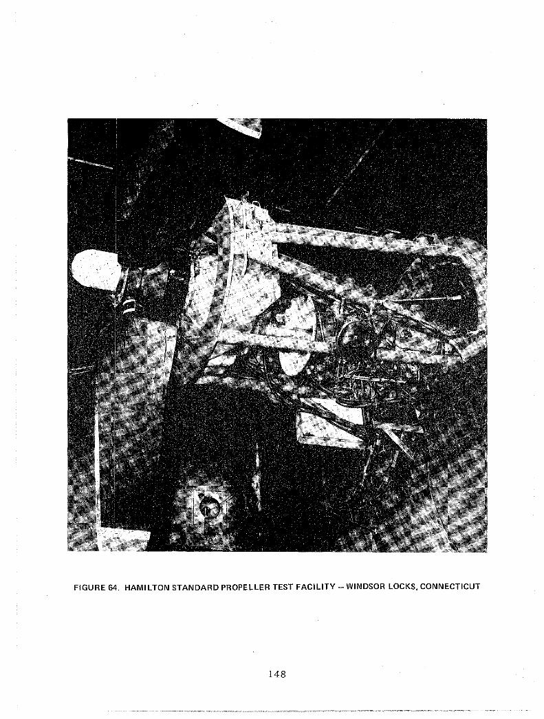
FIGURE 64. HAMILTON STANDARD PROPELLER TEST FACILITY - WINDSOR LOCKS, CONNECTICUT
148

FIGURE 65. DETROIT·DIESEL·ALLISON ENGINE TEST FACILITY - INDIANAPOLIS, INDIANA
149

FIGURE 66. DOUGLAS OUTDOOR ENGINE TEST - QUARTZSITE, ARIZONA
150
The peak prop-fan loading and overspeed performance will be monitored and the
data will be compared to that obtained in the initial ground tests.
Prior to the prop-fan/engine being installed on the aircraft, minimum duty
cycle will be performed to establish reliability of the overall system.
Engine vibration will be monitored and compared to the engine manufactuer's
limits. Vibration measurements will be made on the gearbox and at the
manufacturer's standard Engine Vibration Monitoring locations at stable power
settings during such tests as thrust detemination and duty cycle evaluation.
A more detailed discussion of the acoustic measurements and data desired is
presented in the Acoustics section of Task IV. Brief description is included
here of the acoustic data to be obtained during the ground testing phase of the
flight program. To define the directivity and amplitudes of acoustic pressures
imposed on the fuselage, vertical and horizontal arrays of microphones in the
acoustic near field (within 10 feet [3.05 m] of the prop plane) will be used to
make measurements that are free of the effects of the airplane. This will
allow the subsequent measurements in the presence of the airplane and the
ground surface to be adjusted to other airplane geometries. The engine
conditions to be tested will be the same as those for prop-fan load testing as
described above. Measurements will be made over a range of approach and
takeoff power setting (about 12 stable engine conditions). It is hypothesized
that both the near-field acoustic pressures and the far-field noise will be
adversely affected by reingestion of eddies produced by the prop-fan. More
detailed discussion of the acoustic test program is included in Task IV -
Acoustics.
151

Airplane Modification
The DC-9 Series 10 airplane, with the instrumented JT8D-7 engines used for the
baseline tests, will be modified to allow the installation of the two
calibrated T701-AD-700 engines on the wing, the prop-fan controls, and
associated data acquisition instrumentation. Flight safety features such as
an escape chute will also be installed as part of this aircraft modification
phase. Both cabin sidewalls will be strengthened in the prop-fan plane to
ensure structural integrity for the test ·program. As the testing proceeds,
this baseline acoustic treatment will then be replaced with at least one other
treatment material in an effort to determine an "optimum" acoustic
configuration.
Complete Aircraft Ground Tests
Prior to first flight, ground testing will be accomplished to verify that
structural design requirements have been satisfied. Checkout of prop-fan/
engine and prop-fan/control systems will be accomplished plus determination of
static acoustic and structural loads. The following additional tests will be
performed:
o wing and engine mount structural integrity proof test;
structural integrity;
o complete ground vibration testing to establish the aircraft
modal characteristics;
o engine runs to ensure that all prop-fan controls and instrumentation
is properly integrated with on-board aircraft controls. (The
critical prop-fan dynamic and static load strain gages will be
monitored during this test phase to define safety limits.)
o Prop-fan wake measurements to assess the possible effects on wing
surfaces and JT8D engine inlet
Discussion of acoustic results from the aircraft ground testing is included in
Task IV.
152

Low and high speed taxi runs will be performed initially, without the prop-fan
engines operating, to assess the aircraft's handling characteristics and to
ensure that all instrumentation is functioning correctly. Engine mount and
wing oscillatory loads are to be monitored.
High-speed taxi runs will then be conducted to determine the effects of
prop-fan-induced eddies on aircraft acoustic characteristics. Pass-by noise
will be recorded with ground level microphones located in arrays both
perpendicular and parallel to the runway. This will enhance the development of
testing and/or analysis techniques to estimate flyover noise based on static
noise. Due to prop-fan engine power limitations, only one or two pitch angles
will likely be tested during the high-speed taxi tests.
Flight Tests
The flight testing program is divided into three phases:
Phase I
Phase 2
Phase 3
DC-9-10 baseline testing including JT8D-7 engine calibration and
wing pressure surveys; aircraft will be operated out of the Long
Beach facility.
DC-9-10 prop-fan testbed aircraft demonstration and minimum
tests ~equired to prove airworthiness, structural integrity,
performance and acoustic characteristics of the prop-fan
propulsion system. Tests to be performed during this Phase 2
are discussed in subsequent paragraphs. Unless otherwise
stated, the testbed aircraft will be based at Yuma, Arizona.
Accomplish any additional NASA required testing such as
evaluation of an alternate fuselage structure; this is undefined
at this stage and will not be discussed further.
153

Stability and Control
The aircraft will be instrumented to provide control surface positions and
forces, aircraft attitude, center of gravity, and normal, lateral and
longitudinal accelerations. These tests will be performed with both prop-fan
engines furthest forward on each wing (Figure 67) as this represents the worst
case condition. These tests are to be performed to establish satsifactory
handling characteristics; and the tests must be performed before the objectives
can be safely investigated.
(PROPELLER RAKE
PIVOT
ffi ~ FAIRING g OVERLAP
I
CD
A-A
ADJUSTMENT FOR NACELLE TILT - 0 TO 3 DEG (0.032 rad) (NOSE DOWN)
81·DC9·91273 A
FIGURE 67. EFFECT OF PROP-FAN LOCATION RELATIVE TO WING
Directional Stability and Rudder Effectiveness Directional stability will
be assessed for takeoff and landing configurations with both JT8D engines
operating and then with one engine at idle and the prop-fan feathered. Further
assessment will be made in the cruise configuration at various power settings
with both prop-fans rotating in the same direction and with both rotating up
and inboard to the fuselage.
154

Lateral Control and Aileron Effectiveness Lateral control during rolling
maneuvers will be assessed in takeoff and landing configurations with both JT8D
engines operating and then with one engine at idle and the prop-fan feathered.
Further assessment will be made in the cruise configuration at various power
settings with both prop-fans rotating in the same direction and with both
rotating up and inboard to the fuselage.
Static Longitudinal Stability Static longitudinal stability will be
assessed in takeoff, landing and cruise configurations with the prop-fans
feathered. A limited assessment will be made for the cruise operation with
both prop-fans operating.
Dynamic Longitudinal Stability Dynamic longitudinal stability will be
assessed in takeoff, landing and cruise configurations with the prop-fans
feathered. A limited assessment will be made in the cruise configuration with
the prop-fans operating.
Dynamic Lateral-Directional Stability (Dutch Roll Mode) Dynamic
lateral-directional stability will be evaluated in both cruise and landing
configurations with the prop-fans feathered, and in the cruise configuration
only with the prop-fans operating at various power settings. Checks will be
made with both prop-fans rotating in the same direction and with both rotating
up and inboard to the fuselage. Dutch roll oscillations will be produced using
pilot inputs, and the damping will be recorded after the controls have been
released.
Approach to Stall The aircraft handling qualities down to a speed of 1.3
Vs will be assessed with the prop-fan engine off and with prop-fan feathered in
the landing, takeoff, and cruise configurations.
Structural and Aerodynamic Damping
Flutter characteristics will be investigated at 24,000 feet and 30,000 feet
(7,315 and 9,144 m) with the prop-fan engines operating, and at 24,000 feet
(7,315 m) with the prop-fan engines off and prop-fans feathered. The case of
fuel in one wing and the prop-fan engines in the forward position will be
tested. The whirl mode flutter characteristics will be assessed during this
testing. 155
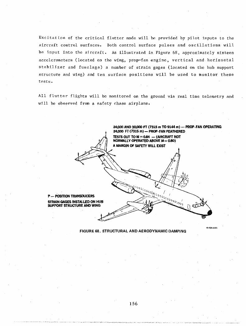
Exci ta t ion of the critical flutter mode will be provided by pilot inputs to the
aircraft control surfaces. Both control surface pulses and oscillations will
be input into the aircraft. As illustrated in Figure 68, approximately sixteen
accelerometers (located on the wing, prop-fan engine, vertical and horizontal
stabilizer and fuselage) a number of strain gages (located on the hub support
structure and wing) and ten surface positions will be used to monitor these
tests.
All flutter flights will be monitored on the ground via real time telemetry and
will be observed from a safety chase airplane.
P - POSITION TRANSDUCERS
STRAIN GAGES INSTALLED ON HUB SUPPORT STRUCTURE AND WING
24,000 AND 30.000 FT (7315 m TO 9144 m) - PROP-FAN OPERATING 24,000 FT (7315 m) - PROP-FAN FEATHERED
TESTS OUT TO M = 0.84 - (AIRCRAFT NOT NORMALLY OPERATED ABOVE M = 0.80) A MARGIN OF SAFETY WILL EXIST
81-GEN·21851
FIGURE 68. STRUCTURAL AND AERODYNAMIC DAMPING
156

Loads Monitoring
During the envelope expansion, the prop- fan assessment, and the takeoff and
landing tests, critical load parameters will be monitored to assess the static
and oscillatory load environment. Components included in the monitoring are
horizontal and vertical stabilizer, wing and pylon, engine mounts, prop-fan
blades, and the prop-fan engine.
The effect of v8riation in prop-fan engine tilt and location relative to the
wing on the prop-fan blade stress will be assessed. The prop-fan engine tilt
can be varied from 0 degrees to 3 degrees (0 to .052 radians), and three engine
locations aft relative to the wing are possible. The method of achieving this
variation is presented in Figure 59 and a description is given in Task V.
Loads measurements will be made at several engine power settings and prop-fan
blade pitch angles. Maneuvers to 80 percent aircraft normal 'g' capability
will be performed at a TBD engine configuration with and without the prop-fan
engines operating. A high speed motion camera will be positioned to film the
prop-fan. Loads will be recorded during all phases of testing. Specific tests
will be performed at the speeds and altitudes indicated in Figure 69.
(16) 50
• PROPOSED TEST POINTS
..... Ii: § (12) §40
... ...
.... .... Q :::l Q 30 !::
(8) ~ !:i oC(
oC(
20
(4)
10 100 150 200 250 300 350 400
EQUIVALENT AIRSPEED· KNOTS I I I I I
(200) (300) (400) (500) (600) (700)
EQUIVALENT AIRPSEED (km/HR) "DC"'"''
FIGURE 69. PROPOSED LOADS TEST POINTS
157

Propulsion
Throughout the prop-fan engine testing, critical parameters will be monitored.
An anti-icing system for the inlet or prop-fan is not provided, and so the
prop-fan will not be operated in icing conditions. All safety critical flights
will be monitored on telemetry and observed from a chase aircraft. The initial
start of one and then both prop-fan engines will also be observed from a chase
aircraft. The gas generator will be initially started at low Mach number and
altitude with feathered prop-fans and windmilling engines. The prop-fan will
then be accelerated from feather to test RPM with pitch schedule for zero
thrust. Prop-fan pitch angle will then be increased. The initial engine
operating envelope expansion will be performed with the engine at one location
relative to the wing and one pitch attitude.
Variations of engine location and pitch attitude are discussed in a subsequent
paragraph under Loads Monitoring.
Airstart Envelope An acceptable airs tart envelope for the prop-fan
operation, within approximate 15,000 feet to 30,000 feet (4,572 to 9,144 m),
will be defined. As mentioned previously, this lower limit for the safe
operation of the prop-fan system is dependent on results of subscale wind
tunnel stability and control tests.
Engine Characteristics Tests will be performed throughout the aircraft
operating envelope. Demonstration that the prop-fan feathers correctly will be
included. The check out of the engine and gearbox oil systems, the prop-fan
pitch control system, the engine mount and related structural loading will be
included. The engine safety systems and instrumentation will also be checked.
The effect of the prop-fan propulsion system on DC-9 aerodynamics, structural
loading, and acoustics characteristics will be assessed. The operation of the
DC-9-10 testbed on the two prop-fan engines only requires that the aircraft
flys at a reduced speed and weight.
158

Prop-fan Overs peed
altitudes and airspeeds.
Prop-fan overs peed tests will be conducted at various
Prop-fan Performance A pressure rake located just behind the left prop-fan
engine rotor will provide a pressure survey to define the local flow field
ahead of the engine inlet and to determine prop-fan efficiency (see Figure 29).
Data will be taken at various blade pitch angles and RPM settings. Tests will
also be conducted to assess the impact of nacelle location, engine pitch
attitude (variations described in the Loads Monitoring paragraph), and
prop-fans rotating conventionally or in opposite directions.
Acoustic and Vibration
The desired acoustic testing, both ground gnd flight, for the testbed is
discussed in detail in Task IV. Reference to this discussion on the relative
value of subscale tunnel testing, ground testing, and large scale flight
testing, as well as required instrumentation and location of data recording
equipment, is apropos for this acoustic flight test program.
159

Cruise Performance/Wing and Nacelle Pressure Survey
If the testbed flight testing is turned over to NASA Dryden upon the completion
of the Douglas flight testing, which encompasses the basic component testing
and proof of airworthiness, then NASA Dryden would perform the prop-fan
aircraft cruise performance, including the wing and nacelle pressure data,
installed prop-fan characteristics, and further acoustic data. If the prop-fan
testbed is not turned over to Dryden at this point, Douglas will continue with
the flight testing.
Cruise performance will be determined at two W/ 0 I S (weight/atmospheric
pressure ratios) at the selected Mach/altitude operating points noted in Figure
70.
TWO WEIGHT I ATMOSPHERE PRESSURE RATIOS ONE ENGINE POSITION (16) SEVERAL POWER SETIINGS PROP-FAN REMOVED
50
• TEST POINTS - t: § (12) §40 .... .... -LLI
C ~ !::
(8) ~ 01(
(4)
LLI c 30 ~ t-t= ...J 01(
20
10 100
I (200)
150
(300)
." ~o :~ '"O----+-~-
200 250 300 EQUIVALENT AIRSPEED - KNOTS
I I (400) (500) (600)
EQUIVALENT AIRPSEED (km/HR)
350 400
(700)
61·DC9·91277e
FIGURE 70. CRUISE PERFORMANCE/VVING AND NACELLE PRESSURE SURVEY
160

The flight tests will be performed with both prop-fans operating and with the
prop-fans removed. From these tests, the net installed thrust-minus-drag of
the prop-fan propulsion system will be obtained using the calibrated JT8D
engines and the previously described DC-9 baseline flight test data.
Testing with both prop-fans operating include:
o varying power settings;
o optimum nacelle tilt and location relative to the wing
(as previously defined by flight test);
o prop-fans rotating conventionally (in the same direction)
and with opposite rotation so both prop-fans rotate up and
inboard to the fuselage.
T70l nozzle thrust will be removed analytically using nozzle exhaust pressure
and temperature data. Prop-fan thrust and efficiency will be obtained using
calibrated thrust strain gage and shaft balance data.
To isolate the effects of power from the effects of the nacelle and to obtain
reference pressure data on the nacelle for buoyancy corrections, the prop-fans
will be removed and the same flight test points flown. For this case the inlet
and nozzle will be faired over to remove momentum losses.
Wing and nacelle pressure data will be obtained during cruise performance
testing; these data will provide the diagnostic information to interpret the
force results. Necessary pressure survey instrumentation locations on the
aircraft are illustrated in Figure 29.
Preliminary Test Schedule
Figure 71 presents an estimated schedule of the flight test effort which
involves the opening of the DC-9-10 prop-fan flight envelope and airworthiness
testing. Further flight testing which may be done at either Dryden or at
Douglas is not included in this figure.
161

BASELINE FLIGHT TEST
MODIFY AIRCRAFT AND INSTALL PROp· FAN
GROUND TEST PROOF TEST GROUND VIBRATION TEST ENGINE RUNS TAXI TRIALS
FLIGHT TEST STABILITY AND CONTROLS STRUCTURAL AND AERODYNAMIC DAMPING POWERPLANT PROPELLER PERFORMANCE LOADS SURVEY CRUISE PERFORMANCE/PRESSURE SURVEY ACOUSTICS AND VIBRATION
0 [[]
I
A 1 .1 I' 5
I
I
I
10 WEEKS
FIGURE 71. PRELIMINARY FLIGHT TEST SCHEDULE
ONE NACELLE PROP-FAN CONFIGURATION
I I
15 20 23 81·GEN·21855A
The foregoing discussion of the flight testing has assumed a two nace11
prop-fan configuration. As per the contract Statement of Work, the one
nacelle prop-fan configuration is also considered. The flight testing
procedures for the two configurations are the same with the exceptions
noted below which are not compatible with the one prop-fan configuration:
o effects due to opposite prop-fan rotation;
o synchronization;
o proper evaluation of representative acoustic loads, interior
noise, and vibration.
The acoustic and vibration data obtained from the one nacelle prop-fan
configuration requires considerable adjustment to remove the asymmetric
effects so that these acoustic results may be properly projected to a
realistic prop-fan DC-9-10 configuration.
162


TASK VII
LARGE SCALE WIND TUNNEL PROGRAM PLAN
COMPATIBILITY OF LARGE SCALE FLIGHT HARDWARE AND WIND TUNNEL TEST MODEL
As part of the overall program development, the possibility of using the flight
hardware in a wind tunnel test to satisfy program objectives is investigated.
The prop-fan/engine/nacelle/wing integration system, described in Task V, to be
installed on the testbed aircraft does lend itself particularly well as a large
scale wind tunnel model. As can be seen in Figure 72, the nacelle parting line
from the flight testbed installation is behind the engine installation and
ahead of the wing front spar.
ALLISON I70l ENGINE HAMILTON STANDARD
---j-- 9.5·FT 12.9 m) DIAMETER PROP·FAN, TEN·BLADE
/
NACELLE PARTING LINE FROM FLIGHT TESTBED INSTALLATION
Ji;fl""-t----:-7--i-
I~:l=-----..s:~~~~;;:::-:-=-:- NO INTERFERENCE WITH WING STRUCTURE
aO·GEN-27414A
FIGURE 72. COMPATIBILITY OF PROP·FAN/ENGII\lE/NACELLE FLIGHT TEST INSTALLATION WITH WIND TUNNEL TEST MODEL
Such an arrangement permits the testbed installation of the prop-fan/engine/
nacelle/inlet to be utilized as the large scale wind tunnel test model. The
problems of availability of adequate sized wind tunnel facilities for the total
large scale tests or the strength requirements suitable for a wind tunnel model
are discussed in the subsequent paragraphs.
163

These facilities and hardware are different from the Aerodynamics development
plan described in Task IV where subscale models are used to establish flight
safety boundaries and efficient wing/nacelle external contours. Throughout
discussions in this Task VII, the term "large scale" refers to the prop-fan
diameter of 8 foot (2.44 m) or greater. For the program considered here, it is
required that the same prop-fan and fuel burning engine hardware used in flight
be tested in the tunnel. Static, low speed, and high speed conditions are
considered. At high speed conditions, it is necessary to simulate flight
conditions at Mo = 0.8 and 30,000 feet (9,144 m). The objectives of the tests
are to evaluate the prop-fan blade loads, thrust minus drag, surface pressures
and inlet characteristics.
LARGE SCALE WIND TUNNEL CHARACTERISTICS
A survey is made of available wind tunnels; and those facilities that may be
useful to fulfill these requirements are:
Ames 40 x 80 (low speed only)
AEDC 16 foot
Lewis Altitude Facility
ONERA Sl 8 meter
A summary of the characteristics of these four wind tunnels is given in Figure
73. The wind tunnel capabilities and limitations are presented in Figure 74.
A proposed installation for each facility, together with a more detailed
description of the capabilities, limitations, and tunnel interference effects,
is presented in Appendix I. The tunnel interference effects are evaluated by
calculating the solid blockage and comparing it to accepted testing practice
and by calculating the incremental solid wall tunnel velocity errors produced
by the prop-fan. The latter correction is based on the work of Glauert
(Reference 5) using the ratio of the prop-fan to tunnel cross-sectional area
and the ratio of the prop-fan thrust to tunnel dynamic pressure.
164

WIND TUNNEL/AVAILABILITY MACH ALtiTUDE MODEL INSTALLATION NUMBER FT ml CURRENT
~itl ~ ~ SL--> AEDC 16 FT 0.2 .. 0.8 30K* TULLAHOMA, TENNESSEE (91441
STRUT SUPPORT NO WING PARTIAL SPAN
- 1985
ffi ~ LEWIS ALTITUDE - 20 FT OR 45 FT SL'"
0.2--> 0.8 30K NASA LEWIS RESEARCH CENTER (9144) CLEVELAND, OHIO
PARTIAL SPAN
CURRENT
+~1~ ONERA SI- 26 FT SL ...
MODANE, FRANCE 0.2-> 0.8 11K (3353)
PARTIAL SPAN
- 1982
I ~ w ,I~ AMES 40 FT BY 80 FT NASA AMES RESEARCH CENTER 0.45 STATIC I MOUNTAIN VIEW, CALIFORNIA 9().PERCENT SPAN
PLUS FUSELAGE FULL SPAN PLUS FUSELAGE ·PRESSURE SIMULATION ONLY. TEMPERATURE IN ERROR
60·GEN·27434A
FIGURE 73. SURVEY OF PROBABLE WIND TUNNEL FACILITIES FOR PROP-FAN TESTBED TESTING
-::. LLI
0 > > * . a::: l- I-LLI Q: 0 ~
IIJ LLla::: 0 :::i :::i == LLI .... 0' iii ~ I- iii < ~ of2 Z .... a:::
C:':: 0<- < :3 Z .... Z::E LLI -LLIO :::ig > ~ I-C~ :3~ < a::: 0 < < " ""0 a::: !a0~ 0"" > <)( 0 :> cn/XI <l /XI < :lzf2 C5 ~::E~ <
AEDC 16-fOOT STRUT Mo= 0.2 3% 8% MUST SUPPORT Mo = 0.8 t <1% BE
! ADAPTED PARTIAL SPAN Mo = 0.2 9.8% 1.1 l WING SUPPORT Mo = 0.8 0.2
LEWIS ALTITUDE TUNNEL Mo = 0.2 (45 fT) 4% 1% ? ? ? ? 1985 Mo = 0.8 (20 fT) 9.7% <1%
ON ERA SI 8 METER Mo = 0.2 7.2%
4% 0.8 Mo = 0.8
t <1% 0.07
AMES 40 BY 80 Mo = 0.45 fLOOR MOUNT 5.5% 1% 0.55 1982 STRUTS MOUNT 3.4
*T701INSTALLATION 8O·GEN·27575 A
FIGURE 74. WIND TUNNEL CAPABILITIES AND LIMITATIONS SUMMARY
165

Wind Tunnel Model Strength Requirements
As a matter of safety precaution for protection of wind tunnel facilities,
equipment, and associated personnel, strength requirements of the models to be
tested in wind tunnel facilities are imposed. Generally, all hardware tested
in wind tunnels must meet one of the following strength criteria:
o Analytically demonstrate that predicted loads of any structural
component do not exceed -
one-fifth the ultimate tensile strength, or
one-third the yield strength.
o Static proof test critical model components to three times the maximum
predicted load.
o Static proof test critical model components to two times the maximum
predicted load if the aerodynamic load is directly or continuously
monitored.
Plots of deflection as a function of load for a complete loading cycle shall
show no permanent set.
When considering the use of flight hardware as a wind tunnel test model, the
structural integrity of the test item must meet with the tunnel specifications
for strength requirements. In general, these requirements are greater than
that necessary to satisfy the structural integrity of the flight hardware
component.
LOW SPEED WIND TUNNEL TESTBED INSTALLATION
The largest wind tunnel that will accommodate tests requiring fossil fuel
burning engines is the NASA Ames 40 x 80 foot tunnel. This tunnel operates at
sea level total pressure at speeds up to 0.45 Mach number. The tunnel size
will allow testing of a complete semi-span wing and fuselage if the airplane is
mounted horizontally on three tunnel support struts (Figure 73d). These struts
166

will allow both pitch and sideslip angle variation. Lift coefficients up to
3.4 are within the capability of the tunnel balance, and the balance drag link
is sufficiently strong to allow testing of the prop-fan engine at full power
when the thrust is approximately 7,500 pounds (3,104 kg).
If the airplane is split at the plane of symmetry and mounted on the balance
turntable in the tunnel floor with the wing vertical, the wing must be clipped
at 90 percent semi-span, as referred to the DC-9 (Figure 73d). The balance
load capacity limits the lift coefficient to 0.55 for this mounting arrangement
and the model cannot be tested in sideslip. The tunnel interference effects
are assessed by evaluating the tunnel solid blockage and the incremental
velocities produced by the prop-fan thrust. The solid blockage, in either
case, is about 5.5 percent which is high but acceptable for low speed testing.
The tunnel velocity correction due to power is small, less than 1 percent.
HIGH SPEED WIND TUNNEL TESTBED INSTALLATION
The large wind tunnels which will accommodate fossil fuel burning engines and
provide test Mach numbers of 0.8 are the AEDC 16-foot Transonic Tunnel, the
ONERA S1 (26-foot diameter) Tunnel in Modane, France, and the NASA Lewis
Altitude Tunnel with the proposed improvements. Of these, only the Lewis
Altitude Tunnel with the proposed improvements provides proper simulation of
both the temperature and pressure at 30,000 feet (9,144 m) altitude. However,
this facility will probably not be available for four or five years, too far
downstream to aid this phase of the prop-fan program. The AEDC 16-foot Tunnel
will allow simulation of the pressure at 30,000 feet (9,144 m); however, the
tunnel heat exchangers do not have the capacity to cool the tunnel air to 412
degrees Rankine, the standard temperature at 30,000 feet (9,144 m). The ONERA
S1 Tunnel operates at an ambient total pressure, therefore, at a Mach numer of
0.8 the test section static pressure is approximately equal to the pressure at
11,000 feet (3,352 m).
Because of the limited size of the test sections of these facilities, only
partial span wings can be tested with the prop-fan engine and nacelle. Figures
73a, 73b and 73c depict the installation considered for each facility. As
shown in Figure 73a, the stub wing is to be supported in the AEDC 16-foot
167

tunnel with a trunion system. The airloads and engine thrust are measured with
the largest existing six component strain-gage balance available. However,
because of the large area of the wing, the balance normal force limitations of
16,000 pounds (7,256 kg) limits the lift coefficient to approximately 0.2 at a
Mach number of O.S. In addition, the solid blockage of the installation
studied is 9.S percent, well above the acceptale level of 0.5 percent. Similar
installations were studied for the ONERA S1 tunnel, Figure 73c, and for the
NASA Lewis Altitude Tunnel, Figure 73b. The available ONERA balance limits the
lift coefficients to an unacceptably low value; the balance for the Lewis
Altitude Tunnel is undefined. The solid blockage in these facilities, 7.2 and
9.7 percent, respectively, will result in erroneous force data.
In addition, since the size of available tunnels limits testing to a partial
span wing, the wing tip is not present which means that the downwash, sidewash,
and spanwise lift distribution of the wing in the propeller/nacelle region are
not properly simulated. The missing wingtip and the distortion of the loading
caused by the wind tunnel walls, will modify the vortex wake downstream of the
wing, thereby modifying the downwash in the wing plane which is the cause of
induced drag. Prop-fan power effects on the span loading are not properly
represented because of the interaction of the prop-fan wake and wing trailing
vortex wake are also not properly simulated. The local flow fields in the
region of the propeller nacelle is also incorrect. The factors discussed above
lead to the conclusion that the proper thrust and drag cannot be obtained in
the tunnel using flight size hardware.
Since the use of a partial span wing is not satisfactory, the most promising
test installation appears to consist of the engine nacelle mounted on a blade
strut support with no wing (Figure 73a). This installation permits evaluation
of the engine thrust at static, takeoff, and cruise conditions. The angle of
the airflow in the plane of the prop-fan can be approximated by adjusting the
angle of incidence of the engine and nacelle. Because of the pressure altitude
simulation capability and the availability, the AEDC 16-foot transonic tunnel
would be the preferred facility in which to conduct the isolated strut mount
prop-fan engine test.
168

Although the strut mounted engine test in the AEDC 16-foot tunnel will yield
the most meaningful data, the results will not satisfactorily fulfill all of
the test requirements. Since the engine is to be tested without the influence
of the wing, the upwash and sidewash caused by the wing flow field are not
present and the proper levels of engine thrust-minus-installed-drag cannot be
measured.
A rough order of magnitude estimate indicates that the cost of preparing an
engine for test on a blade strut in the AEDC 16-foot tunnel, designing and
fabricating the support system and balance mounts, conducting the test, and
preparing pre-test and post-test reports are approximately $450K, in 1981
dollars, and requires approximately eight months to complete. The cost
estimate assumes that the tunnel is to be furnished at no expense to DAC.
LARGE SCALE WIND TUNNEL RECOMMENDATIONS
The results of the study of the feasibility of testing the prop-fan flight
hardware in a wind tunnel, summarized in Figure 74, clearly indicate that all
the desired test data cannot be obtained. Using the only reasonable
installation, the isolated-strut mounted nacelle in the AEDC 16-foot tunnel,
the approximate engine thrust can be obtained; however, because of the large
diameter of the prop-fan relative to the tunnel size, the data will be
questionable. Since there is no wing in the tunnel, the installed thrust minus
drag cannot be determined. The prop-fan loads may be approximated by setting
the engine angle of attack at values derived from a three dimensional analysis
of the wing flow field; however, the variation of flow field angles across the
prop-fan disc cannot be simulated.
An overall evaluation of the wind tunnel as a means of obtaining proper large
scale prop-fan/engine/nacelle data results in the following conclusions:
169
Flow Simulation
o None of the tunnels will accommodate a complete span model
at Mo = 0.8.
o Upwash and sidewash cannot be simulated.
o All tunnels have balance normal force limitations with a partial
span wing at Mo = 0.8 and 30,000 feet (9,144 m) simulation.
o Lewis Altitude Tunnel will not be available until at least 1985.
Thrust Minus Drag
o Cannot measure because of partial span wing.
o Proper airfoil section drag cannot be obtained due to
balance normal force limits.
For test conditions at M ~ 0.45, the prop-fan loads, thrust-drag, and isolated
prop-fan efficiency are obtainable from appropriate wind tunnel tests.
However, for the test conditions of Mcruise of 0.80, these prop-fan loads and
thrust-drag data are not obtainable; even the results for prop-fan efficiency
are questionable. Because of the inadequacy of the wind tunnel test results,
it is recommended that the DC-9-10 prop-fan flying testbed be used to obtain
the aerodynamic data for the prop-fan configuration at large scale. Reliable
acoustic data must also be obtained from flying testbed results.
170

ROM COSTS OF TWO-NACELLE PROP-FAN TESTBED PROGRAM
BACKGROUND
The estimated costs for the two-nacelle prop-fan testbed are based on a
detailed evaluation of the WBS elements identified in Appendix II. Wherever
possible, the buildup of manhour estimates were made from very similar effort
accomplished in the recent past. There were several NASA sponsored programs
that involved flight tests on a DC-8 and a DC-9 aircraft that were specifically
related to the propulsion system on the aircraft. The DC-8 "Quiet Engine
Program" consisted of modifications and special acoustic treatment designs on
all four nacelles. The DC-9 "Refan Program" consisted of design, wind tunnel
testing, fabrication of new nacelles, and pylon support structure for a rebuilt
JT8D-9 engine that was converted to a larger diameter JT8D-209 engine. In
addition, a recently completed program for the Air Force called PABST (Primary
Adhesively Bonded Structure Test) involved the design and fabrication of tools
and components for a single major test assembly. A very recent program that
involved a considerable number of high and low speed and flutter wind tunnel
models, as well as the design and construction of one set of flight test parts,
was the DC-IO Winglet Flight Evaluation Program. All of the above programs
have very similar work efforts that are identified in this prop-fan program.
It is noteworthy to indicate that all of the above-mentioned programs were
accomplished on schedule and within budget.
MAJOR ELEMENT DESCRIPTION
Preliminary Design Through PDR
All major functions that are to participate on the program are to be assigned
and co-located in one area and to work together in establishing the design of
the nacelle installation on the wing in a most cost effective manner
considering design, tooling, fabrication, assembly, and installation which will
result in a preliminary manufacturing plan. In parallel with this effort the
specific definition of all the model programs is to be drafted into preliminary
planning documents. In conjunction with the engine/gearbox subcontractor and
171

propeller supplier, a draft plan for large scale ground testing, taxi testing
and flight testing is to be prepared. All the preliminary planning documents
are to be provided at the Preliminary Design Review (PDR). In addition, at PDR
the layout drawings for the flight test nacelle, aircraft modification and test
installation will be provided for approval.
Development Testing
Immediately after the PDR approval, the detail definition of all model wind
tunnel testing is initiated. Both high and low speed wind tunnel models of the
test aircraft are considered to be tested in the NASA Ames Research Center
II-foot and 12-foot wind tunnels provided at no Contractor expense. Model
modifications consider nacelles off and on, both powered and unpowered, with
the primary objective of stability and control required to define minimum
operational speeds considering one prop-fan system failure and one test
aircraft primary propulsion system failure. A basic low speed flutter model is
considered essential to the program for methods validation for both the
nacelles on and off. A test aircraft full scale inlet is also considered as
part of this program. The acoustic development tests are in two parts. One
deals with the development of treatment that can be added to the current
structural arrangement of the test aircraft fuselage. The second part of the
acoustic development effort will be the definition and specimen tests of a
newly designed segment of structure optimized for minimum acoustic
transmission. The layout of this section would be suitable for rework into the
test aircraft.
Detail Design
The selection of the flight test nacelle and installation configuration will
have been made as a result of PDR. Upon NASA concurrence, the detail design is
to be initiated for the nacelle and for aircraft modification. The structural
detail design will be established in conjunction with manufacturing tooling in
order to "optimize" for a least cost prop-fan effort. The final design for all
major components will be completed at the Critical Design Review (CDR). At the
time of CDR, the high speed wind tunnel model stability and control, inlet, and
172

acoustic tests should be completed. The low speed tests can be completed after
CDR. At CDR both engine and prop-fan subcontractors will participate to
identify their interface requirements, how they have been satisfied in the
program to date, as well as how the future schedule and interface requirements
are being satisfied. Tooling design and tool fabrication will be nearly
complete at CDR with some component fabrication of parts in progress. At CDR
the flight program instrumentation plan will have been completely definitized.
Ground Tests
The ground test programs will consist of a test stand run of the complete
flight test propulsion assembly. Included will be the test engines, gearbox,
and first set of flightworthy prop-fan blades. Runs to full allowable gearbox
horsepower will be made for systems check-out and operation. The complete
flight test propulsion unit will than be installed in the flight nacelle on the
aircraft. A ground vibration test on the nacelle and aircraft will previously
have been conducted which included represenntativc mass and inertia of the
propulsion system. There may be some question regarding the propulsion system
representation during these ground vibration tests; if serious, the ground
vibration test would be accomplished with the full flight hardware installed.
Engine runs will be accomplished on the aircraft in a tie-down condiction. In
conjunction with the installation check-out, a series of acoustic tests on the
fuselage sidewall will be accomplished. After successful completion of all
static ground runs, the aircraft will undergo a series of taxi tests, up to 100
knots, to measure all structural, acoustic, engine performance, and operational
data. For the purpose of this program, the 40 x 80 wind tunnel testing and
alternate fuselage sidewall are not included in the cost estimates and are
considered options to the basic flight program.
Flight Tests
Flight tests will be initiated after satisfactory completion of all ground
tests and analyses of all key data items. The aircraft flight handling
characteristics will be evaluated without power on the test engines. Included
will be flutter checks for envelope expansion. The test engines will then be
173

air started and operated at increasing horsepower and speed as the aircraft
operational characteristics are determined to be satisfactory. Propeller
performance (aerodynamic, structural, and acoustic) as well as fuselage
acoustic data and nacelle/wing aerodynamic data will be obtained throughout the
prescribed test envelope.
Baseline Flight Tests
The test aircraft, prior to entering modification for nacelle installation,
will be instrumented and a series of flights will be conducted to obtain basic
flight handling and performance data. These basic data will then be a
reference for all prop-fan data to be gathered.
Major Subcontracting
At initiation of the basic or prime contract, a definition of the engine/
gearbox subcontract will be made. For purposes of ROM estimates, information
has been provided by Detroit Diesel Allison (DDA), a Division of General
Motors, for gearbox manufacture and shaft engine preparation in a configuration
suitable for flight test. During preliminary design, DDA will be given a
purchase order to present their role in the program at PDR. For purposes of
this contract effort, the DDA estimate used in the summary cost figures include
engine runs of 50 hours on the dynamometer. The first buildup with a propeller
will be on the Douglas test stand. For the ROM estimates presented, the
prop-fan subcontrct with Hamilton Standard would commence upon receipt of the
flight hardware. All previous effort PDR and CDR would be covered under a
Prop-fan Development Contract with Hamilton Standard. A subcontract with
Hamilton Standard is considered in effect during all ground and flight tests
that included the prop-fan. For ROM estimating purposes, it is assumed that
the two companies identified above will be the only major subcontractors.
Consideration was given to soliciting estimates from a nacelle design and/or
fabricator, but for purposes of the estimates shown in this report, the nacelle
design and manufacture is accomplished by the airframe company.
174
Program Management
The est~mates made in this element consider the direct charge Project
Management which includes a Task Manager from Engineering, Manufacturing and
Flight Test. These personnel are not necessarily full time for the duration of
the program. The Administrative business function for budget and schedule
planning and tracking is also included in this element. Costs for all
estimated reports (monthly, quarterly, planning, test results, etc.) are
included in this section. Oral report preparation and travel are also
considered in this section of the estimates.
Costs
The estimated total program costs, Rough Order of Magnitude (ROM), for a
prop-fan program outlined in the previous paragraphs and outlined more
specifically in WBS format in Appendix II is provided in Figure 75. These ROM
estimates are costs which include all normal burden charges except fee.
Program Schedule
The program schedule from which all the cost estimates were generated was
developed in mid-contract period. The two major subcontractors supplied their
schedule based on the definition of the prop-fan testbed program at that time
(late 1980). The program overall schedule is shown in Figure 76, which
identifies first flight occurring at 44 months from program go-ahead. The
program schedule considers that the first flight prop-fan delivery occurs at 33
months from go-ahead. This schedule coincides with a schedule developed by
Hamilton Standard based on their ability to deliver the flight prop-fan in the
33 month time period (Figure 77). The engine gearbox delivery from DDA is
identified as available in 15 months from go-ahead. DDA go-ahead could occur
as part of the CDR release schedule. The program does consider an earlier
start for DDA so that engine/gearbox fit checks in the test stand and aircraft
can be made well ahead of receipt of the flight rated prop-fan assembly. The
DDA schedule is provided in Figure 78. Also shown on the DDA schedule are
Option 1 and Option 2, which are not considered in this particular program
since the first full propulsion system run with the flight hardware is
identified as a Douglas test stand ground run element.
175

ESTIMATED TOTAL PROGRAM COSTS
ROUGH ORDER MAGNITUDE (ROM)
DC-9-10 TESTBED
(Two Allison T70l Engines)
WBS Element*
1000 Preliminary Design thru PDR
2000 Development Testing
3000 Detailed Design thru CDR
4000 Manufacturing
5000 Ground Tests
6000 Flight Tests
7000 Baseline Flight Tests
8000 Major Subcontracting
9000 Program Management
Test Aircraft Cost (DC-9-10)
TOTAL
$K 1981
(Mid-Year)
1,200
I~ , 560
2,800
6,340
5,635
7,410
2,225
6,500**
4,100
2,500
43,000
*Appendix II for detailed definition of effort considered in each element.
**DDA engine and gearbox plus program support
Hamilton Standard program support.
FIGURE 75. ESTIMATED TOTAL COSTS FOR PROP-fAN TESTBED PROGRAM
176

WBS CALENDAR YEAR 1 2 3 4
1000 PRELIMINARY DESIGN ~PDR I I .
2000 DEVELOPMENT TESTING . 6. CDR WIND TUNNEL TESTING HIGH SPEED
LOW SPEED INLET I
ACOUSTIC TESTS ACOUSTICS
3000 DETAIL DESIGN
4000 MANUFACTUR ING TOOLING TOOLING
FABRICATION FABRI ATION
ASSEMBLY ASSEMBLY
INSTALLATION I
INSTALLATION
TESTING INSTRUMENTATION
5000 GROUND VIBRATION TEST -PROPULSION GROUND TEST DELIVERY OF FLIGHT
T .. PROPULSION SYSTEM PROPULSION SYSTEM INSTALLATION I--ACOUSTIC TESTS io-TAXI TESTS ...-
6000 FLIGHT ENVELOPE CHECKOUT FIRST fLIGHT 6.
FLIGHT TESTS ~ 7000 BASELINE FLIGHT TESTS
_ .. BO-DC'9-93381 B
FIGURE 76. DOUGLAS AIRCRAFT PROP-FAN TESTBED PROGRAM SCHEDULE
CALENDAR YEAR 1 2 3 4
DESIGN AND DRAFT I I J T
CONTROL (MODIFICATION) -BLADE,HUB,ACTUATOR (UTILIZE EXIST AERO BLADE PO)
ALLISON GEARBOX PROGRAM
HARDWARE FABRICATION CONTROL -~ BLADE, HUB,ACTUATOR
TESTING STRUCTURAL CONTROL DEVELOPMENT
WHIRL PROGRAM
PROP SYSTEM ASSEMBLY AND ENG TESTS --DELIVERY OF FLIGHT A TEST ARTICLE
BO·OC-9·933688
FIGURE 77. HAMILTON STANDARD PROP.FAN TESTBED PROGRAM SCHEDULE
177

MILESTONES YEARS 1 2
MFGA 1 2 3 4 5 6 7 8 9 10 11 12 13 14 15 16 17 18 19 20 21 22 23 24
DESIGN ENGINE ADAPTIVE HARDWARE • 11 ... II ••• n ... .. ... II ••
GEARBOX MODS . .. .... II ... I ••• n.1I .. CONTROL MODS ... II ••• II ... II II. II TEST EOUIPMENT
DYNAMOMETER
~ ~ ::' PROP STAND OPTION 1(1, PROP STAND OPTION 11(2,
FABRICATION ENG ADAPTIVE HARDWARE AND GIB MODS CONTROL MODS TEST EaUIPMENT
DYNAMOMETER :: : PROP STAND OPTION I PROP STAND OPTION II
TEST CONTROLS BENCH TEST DYNAMOMETER
=-BUILDUP -INSTALLATION
•• TEST (50 HRI • REMOVAL AND GIB TEARDOWN
PROP STANO OPTION I . .: REASSEMBLY INSTALLATION
i· TEST (50 HR PLUS 50 HR FCT) REMOVAL AND GIB TEARDOWN
PROP STAND OPTION II
~ REASSEMBLY -INSTALLATION
~. TEST (50 HR PLUS 50 HR FCT) REMOVAL AND GIB TEARDOWN
(1) TEST STAND 861 INSTALLATION - MOD OF STAND CURRENTLY IN USE (2) TEST STAND 862 INSTALLATION - MOD OF IDLE STANO FOR aEC INSTALLATION
BO-DC·9·93370A
FIGURE 78. DETROIT·DIESEL ALLISON PROp·FAN TESTBED PROGRAM SCHEDULE
178

CJ:I W (.) ;;:: w a: w LL W a:

REFERENCES
1. Advanced Turboprop Testbed Systems Study, NASA Lewis Research Center,
Contract NAS3-22437, January 22, 1980.
2. "Prop-fan Data Support Study Technical Report," Hamil ton Standard Report
prepared under Contract No. NAS2-9750, NASA Contractor Report 152141,
February 28, 1978.
3. Goldsmith, I. M., "A Study to Define the Research and Technology
Requirements for Advanced Turbo/Prop-fan Transport Aircraft,"
Contract NAS2-10178. NASA Contractor Report 166138, February 1981.
4. Magliozzi, B., "The Influence of Forward Flight on Propeller Noise,"
NASA Contractor Report 145105, February 1977.
5. Pope, A. and Harper, J. J., "Low Speed Wind Tunnel Testing,"
John Hiley & Sons, New York, 1966.
179

This Page Intentionally Left Blank

x C 2 w CI.. CI.. c:(
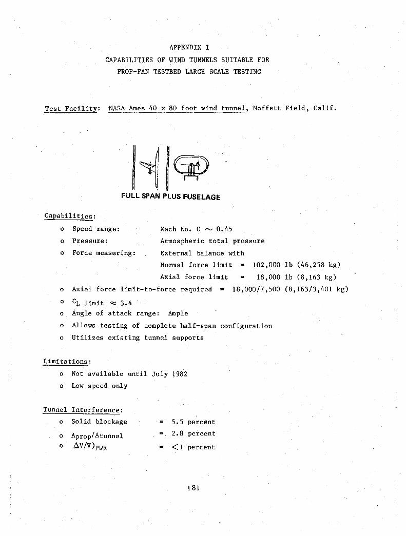
APPENDIX I
CAPABILITIES OF WIND TUNNELS SUITABLE FOR
PROP-FAN TESTBED LARGE SCALE TESTING
Test Facility: NASA Ames 40 x 80 foot wind tunnel, Moffett Field, Calif.
FULL SPAN PLUS FUSELAGE
Capabilities:
o Speed range:
o Pressure:
o Force measuring:
Mach No. 0 ~ 0.45
Atmospheric total pressure
External balance with
Normal force limit = 102,000 lb (46,258 kg)
Axial force limit = 18,000 lb (8,163 kg)
o Axial force limit-to-force required = 18,000/7,500 (8,163/3,401 kg)
o CL limit ~ 3.4 o Angle of attack range: Ample
o Allows testing of complete half-span configuration
o Utilizes existing tunnel supports
Limitations:
o Not available until July 1982
o Low speed only
Tunnel Interference:
0 Solid blockage = 5.5 percent
0 Aprop/Atunnel = 2.8 percent
0 ~V/V)PWR = <1 percent
181

Test Facility: NASA Ames 40 x 80 foot wind tunnel, Moffett Field, Calif.
Capabili ties:
o Speed range:
o Pressure:
o Force measuring:
9O-PERCENT SPAN PLUS FUSELAGE
Mach No. ° ~ 0.45
Atmospheric total pressure
External balance with
Normal force limit = 16,400 (7,437 kg)
Axial force limit 18,000 (8,163 kg)
o Axial force limit-to-force required = 18,000/7,500 (8,163/3,401 kg)
o Angle of attack range: Ample
o Allows testing with 90 percent of the model span
and half the fuselage
o Utilizes existing tunnel supports
Limitations:
o Not available until July 1982
o Tip effects not simulated
o Low speeds only
o CL limit ~ 0.55 (16,400 lb [7,437 kg] normal force limit)
Tunnel Interference:
0 Solid blockage 5.5 percent
Aprop/Atunnel = 2.8 percent 0
0 6 V/V)PWR = <1 percent
182
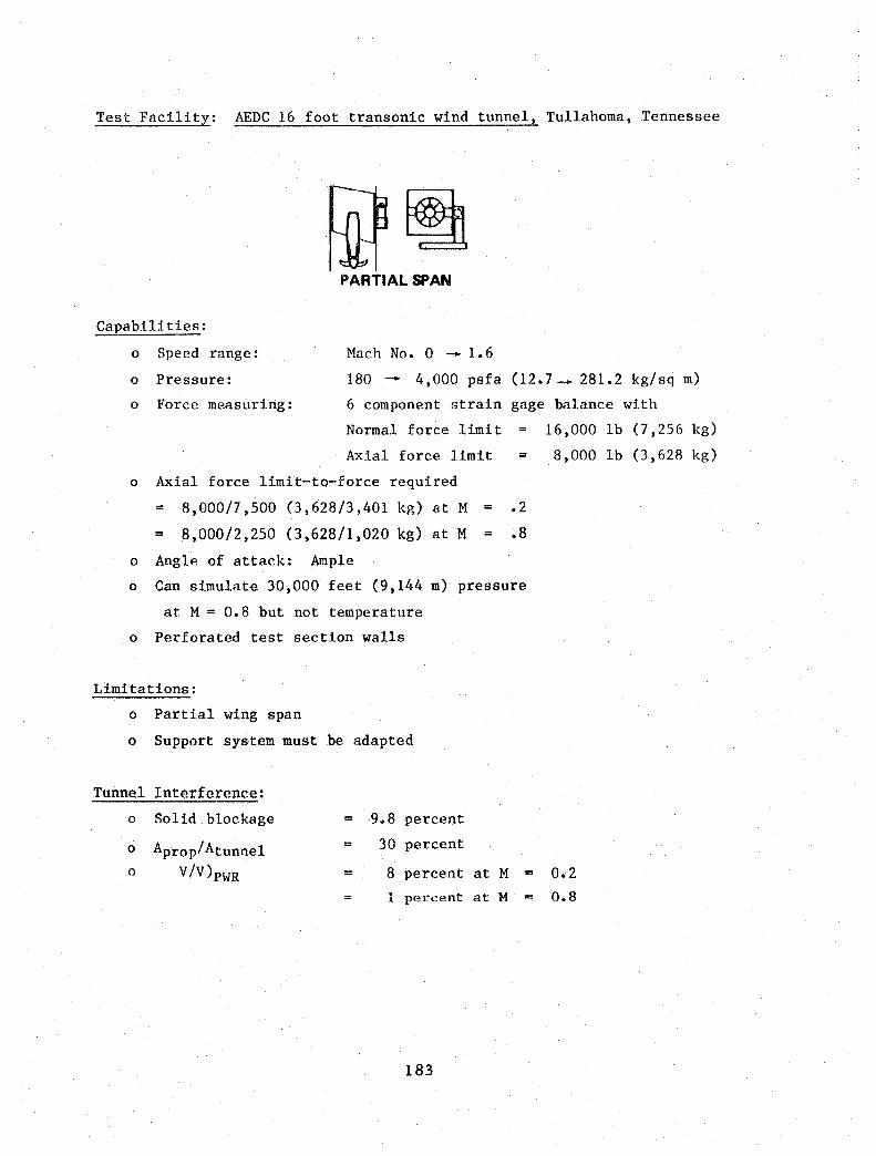
Test Facility: AEDC 16 foot transonic wind tunnel, Tullahoma, Tennessee
.~~ PARTIAL Sl»AN
Capabilities:
o Speed range: Mach No. ° - 1.6
o Pressure: 180 - 4,000 psfa (12.7 _ 281.2 kg/sq m)
o Force measuring: 6 component strain gage balance with
Normal force limit =
Axial force limit
0 Axial force limit-to-force required
= 8,000/7 ,500 (3,628/3,401 kg) at M = .2
= 8,000/2,250 (3,628/1,020 kg) at M = .8
o Angle of attack: Ample
o Can simulate 30,000 feet (9,144 m) pressure
at M = 0.8 but not temperature
o Perforated test section walls
Limitations:
o Partial wing span
o Support system must be adapted
Tunnel Interference:
0 Solid blockage = 9.8 percent
0 Aprop/Atunnel = 30 percent
0 V!V)PWR = 8 percent at M =
1 percent at M
183
16,000 lb (7,256 kg)
8,000 lb (3,628 kg)
0.2
0.8
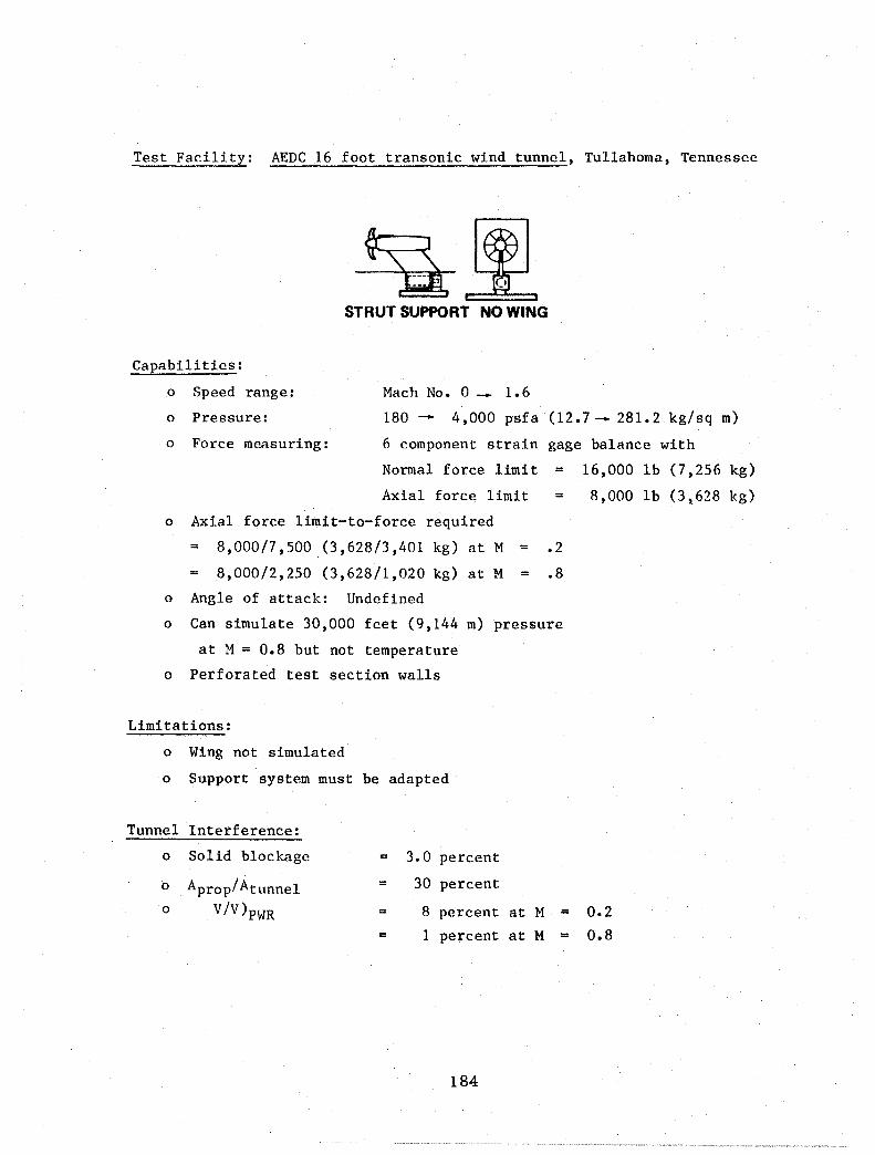
Test Facility: AEDC 16 foot transonic wind tunnel, Tullahoma, Tennessee
STRUT SUPPORT NO WING
Capabilities:
o Speed range: Mac h No. ° _ 1 • 6
o Pressure: 180 - 4,000 psfa (12.7- 281.2 kg/sq m)
o Force measuring: 6 component strain gage balance with
Normal force limit = Axial force limit
0 Axial force limit-to-force required
= 8 , 000/7 , 500 (3,628/3,401 kg) at M = .2
= 8,000/2,250 (3,628/1,020 kg) at M = .8
o Angle of attack: Undefined
o Can simulate 30,000 feet (9,144 m) pressure
at M = 0.8 but not temperature
o Perforated test section walls
Limitations:
o Wing not simulated
o Support system must be adapted
Tunnel Interference:
0 Solid bloc kage = 3.0 percent
0 Aprop/Atunnel = 30 percent
0 V/V)PWR = 8 percent at M =
= 1 percent at M =
184
16,000 lb (7,256 kg)
8,000 lb (3 t 628 kg)
0.2
0.8
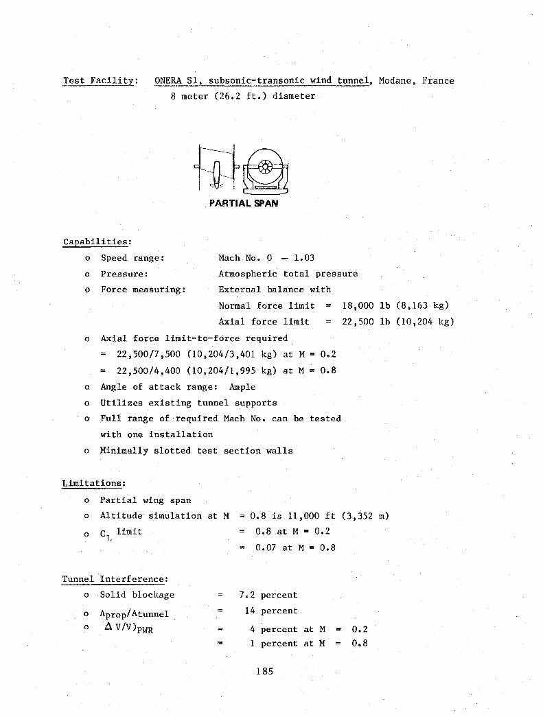
Test Facility: ONERA Sl, subsonic-transonic wind tunnel, Modane, France
8 meter (26.2 ft.) diameter
PARTIAL SPAN
Capabilities:
o Speed range: Mach No. 0 - 1.03
o Pressure:
o Force measuring:
Atmospheric total pressure
External balance with
Normal force limit = 18,000
Axial force limit = 22,500
0 Axial force limit-to-force required
= 22 ,500/7 ,500 (10,204/3,401 kg) at M = 0.2
= 22,500/4,400 (10,204/1,995 kg) at M = 0.8
0 Angle of attack range: Ample
0 Utilizes existing tunnel supports
0 Full range of required Mach No. can be tested
with one installation
0 Minimally slotted test section walls
Limitations:
0 Partial wing span
lb
lb
0 Altitude simulation at M = 0.8 is 11,000 ft (3,352 m)
0 C limit = 0.8 at M = 0.2 L
0.07 at M = 0.8
Tunnel Interference:
0 Solid blockage 7.2 percent
0 Aprop/Atunnel = 14 percent
0 ~ V/V)PWR = 4 percent at M = 0.2
= 1 percent at M = 0.8
185
(8,163 kg)
(10,204 kg)

Test Facility: NASA Lewis altitude wind tunnel, Cleveland, Ohio
PARTIAL SPAN
Capabilities:
o Speed range: Mach No. 0 - 0.8
o Pressure: 1.32 psia ( .93 kg/sq m2) - atmospheric
o Test section diameters: Low speed 45 ft (13.7 m)
o Force measuring:
o Angle of attack range:
High speed
Undefined
Undefined
20 ft
o Revisions to tunnel can be designed to the
test and model requirements
o Proper temperature and pressure simulation
for M = 0.8 at 30,000 ft (9,144 m) altitude
o Slotted test section walls
o Support system exists
Limitations:
o Tunnel not available earlier than 1985
o Partial wing span
Tunnel Interference:
0 Solid blockage 4.0 percent (45 ft
= 9.7 percent (20 ft
0 Aprop/Atunnel = 5 percent (45 ft
= 25 percent (20 ft
0 V/V)PWR = 1 percent (45 ft
= 1 percent (20 ft
186
(6.10 m)
[13.7 mJ diameter)
(6.1 m] diameter)
[13.7 m] diameter)
[6.1 m] diameter)
[13.7 m] diam. at M = 0.2) [6.1 m] diam. at M = 0.8)

x C 2: w c.. c.. <C

APPENDIX II
PROP-FAN FLIGHT RESEARCH PROGRAM
WORK BREAKDmm STRUCTURE (WBS)
Although not a part of the contractual Statement of Work (NAS3-22347), a work
breakdown structure (WBS) through the second level, appropriate to the Prop-fan
Flight Research Program, is included here as Appendix II. This WBS has
previously been submitted to NASA Lewis as ACEE Report 27-PL-1480A, dated May
1981. Further expansion of this WBS is considered apropos as a part of the
response to the upcoming RFP on prop-fan testbed program.
187

SUMMARY
MAJOR WBS ELEMENTS
001 FLIGHT RESEARCH PROGRAM
1000 PRELIMINARY DESIGN
2000 DEVELOPMENT TESTING
3000 DETAIL DESIGN
4000 MANUFACTURING
5000 GROUND TESTS
6000 FLIGHT TESTS
7000 BASELINE FLIGHT TEST
8000 MAJOR SUBCONTRACTING
9000 PROGRAM MANAGEMENT
188

WBS WORKSHEET
1000 PRELIMINARY DESIGN
1100 AERO INSTALLATION DESIGN
1200 STRUCTURAL LAYOUT
1300 INSTALLATION LAYOUT
1400 DEVELOPMENT TEST (PLAN)
1500 MANUFACTURING (PLAN)
1600 GROUND TEST (PLAN)
1700 FLIGHT TEST (PLAN)
1800 PRELIMINARY DESIGN REVIEW
1900 ALTERNATE PROGRAM
189
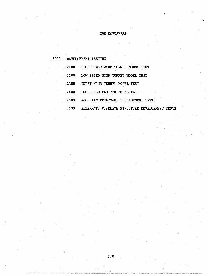
WBS WORKSHEET
2000 DEVELOPMENT TESTING
2100 HIGH SPEED WIND TUNNEL MODEL TEST
2200 LOW SPEED WIND TUNNEL ~10DEL TEST
2300 INLET WIND TUNNEL MODEL TEST
2400 LOW SPEED FLUTTER MODEL TEST
2500 ACOUSTIC TREATMENT DEVELOPMENT TESTS
2600 ALTERNATE FUSELAGE STRUCTURE DEVELOPMENT TESTS
190

was WORKSHEET
3000 DETAIL DESIGN
3100 AERODYNAMIC CONFIGURATION
3200 STRUCTURE
3300 INSTALLATION
3400 AIRCRAFT MODIFICATION
3500 CRITICAL DESIGN REVIEW
191

WBS WORKSHEET
4000 MANUFACTURING
4100 PLANNING
4200 TOOLING
4300 FABRICATION
4400 ASSEMBLY
4500 AIRCRAFT MODIFICATION
4600 INSTALLATION
4700 SUSTAINING ENGINEERING
192

WBS WORKSHEET
5000 GROUND TESTS
5100 INSTRUMENTATION
5200 TEST STAND
5300 GROUND VIBRATION TEST
5400 STATIC ENGINE RUN - INSTALLED
5500 TAXI TESTS
5600 ALTERNATE FUSELAGE SIDEWALL
5700 SUSTAINING ENGINEERING
5800 FORWARD NACELLE 40 x 80 WIND TUNNEL
5900 NACELLE/WING 40 x 80 WIND TUNNEL
193
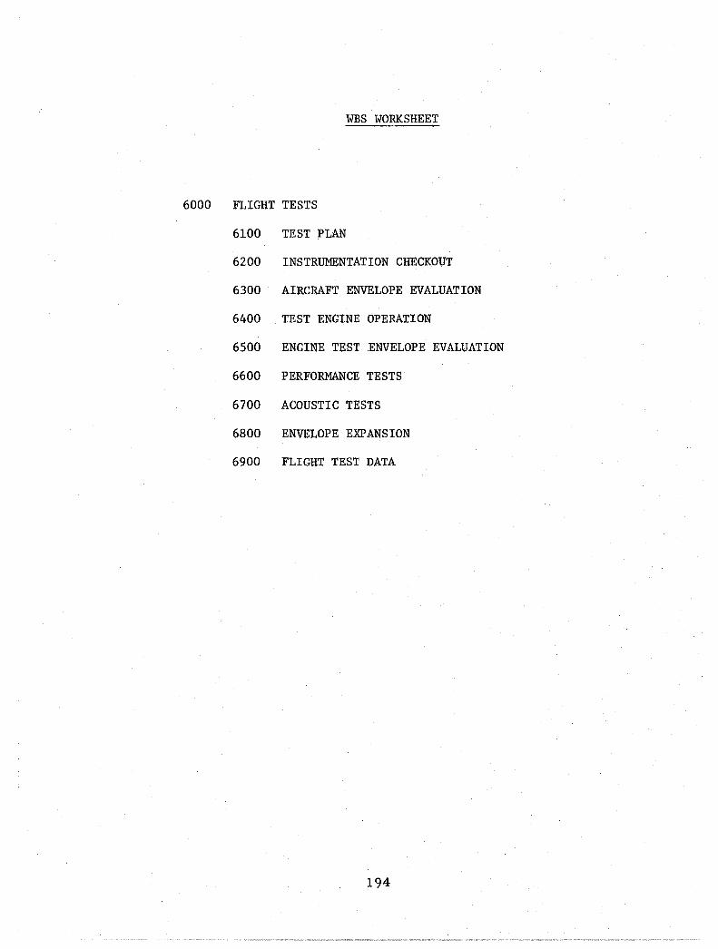
WBS WORKSHEET
6000 FLIGHT TESTS
6100 TEST PLAN
6200 INSTRUMENTATION CHECKOUT
6300 AIRCRAFT ENVELOPE EVALUATION
6400 TEST ENGINE OPERATION
6500 ENGINE TEST .ENVELOPE EVALUATION
6600 PERFORMANCE TESTS
6700 ACOUSTIC TESTS
6800 ENVELOPE EXPANSION
6900 FLIGHT TEST DATA
194
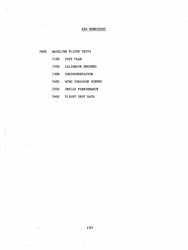
WBS WORKSHEET
7000 BASELINE FLIGHT TESTS
7100 TEST PLAN
7200 CALIBRATE ENGINES
7300 INSTRUMENTATION
7400 WING PRESSURE SURVEY
7500 CRUISE PERFORMANCE
7600 FLIGHT TEST DATA
195

WBS WORKSHEET
8000 MAJOR SUBCONTRACTS
9000 PROGRAM MANAGEMENT
9100 PROJECT MANAGEMENT
9200 ADMINISTRATION BUDGET/SCHEDULE
9300 REPORTS - PERIODIC
9400 ORAL REPORTS
9500 INTERIM REPORTS
9600 FINAL & SUMMARY REPORTS
9700 TRAVEL
196

WBS WORKSHEET
1000 PRELIMINARY DESIGN
1100 AERO INSTALLATION DESIGN
1101 FORWARD NACELLE
1102 AFT NACELLE
1103 ENGINE INLET
1104 OIL COOLER INLET
1105 WING LEADING EDGE
1106 TAILPIPE
1107 AIRCRAFT
1200 STRUCTURAL LAYOUT
1300
1201 FORWARD NACELLE
1202 AFT NACELLE
1203 WING ATTACH
1204 AIRCRAFT MODIFICATION
INSTALLATION LAYOUT
1310 MOUNTING SYSTEM POWER/TRAIN
1320 CONTROLS
1330 FUEL SYSTEMS
1340 OIL COOLING SYSTEM
1350 ACCESSORIES
1360 INLET/EXHAUST
1370 SYNCHROPHASING SYSTEM
1380 EMERGENCY/SAFETY SYSTEMS
1390 PRELIMINARY INSTALLATION SPECIFICATION
197

WBS WORKSHEET
1000 PRELIMINARY DESIGN (CONTINUED)
1400 DEVELOPMENT TESTS (PLAN)
1410 HIGH SPEED WIND TUNNEL MODEL
1420 LOW SPEED WIND TUNNEL MODEL
1430 INLET WIND TUNNEL MODEL
1440 LOW SPEED FLUTTER MODEL
1450 ACOUSTIC TREATMENT DEVELOPMENT
1460 ALTERNATE FUSELAGE STRUCTURE
1470 PRELIMINARY DEVELOPMENT TEST PLAN
1500 MANUFACTURING (PLAN)
1510 PLANNING
1520 TOOLING
1530 FABRICATION
1540 ASSEMBLY
1550 PRELIMINARY MANUFACTURING PLAN
1600 GROUND TESTS (PLAN)
1610 INSTRUMENTATION DEFINITION
1620 FORWARD NACELLE - QUARTZSITE
1630 AIRCRAFT INSTALLATION - PROOF TEST
1640 AIRCRAFT INSTALLATION - GVT
1650 STATIC & TAXI RUNS - ACOUSTIC
1660 DATA REDUCTION AND ANALYSIS
198
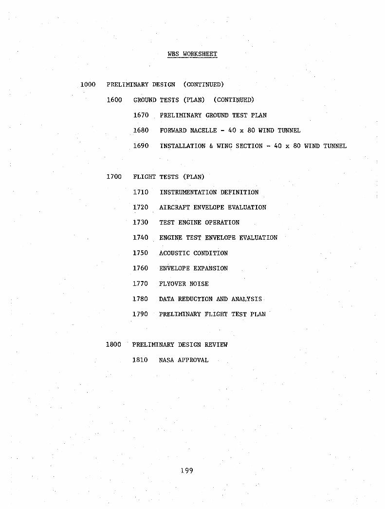
was WORKSHEET
1000 PRELIMINARY DESIGN (CONTINUED)
1600 GROUND TESTS (PLAN) (CONTINUED)
1670 PRELIMINARY GROUND TEST PLAN
1680 FORWARD NACELLE - 40 x 80 WIND TUNNEL
1690 INSTALLATION & WING SECTION - 40 x 80 WIND TUNNEL
1700 FLIGHT TESTS (PLAN)
1710 INSTRUMENTATION DEFINITION
1720 AIRCRAFT ENVELOPE EVALUATION
1730 TEST ENGINE OPERATION
1740 ENGINE TEST ENVELOPE EVALUATION
1750 ACOUSTIC CONDITION
1760 ENVELOPE EXPANSION
1770 FLYOVER NOISE
1780 DATA REDUCTION AND ANALYSIS
1790 PRELIMINARY FLIGHT TEST PLAN
1800 PRELIMINARY DESIGN REVIEW
1810 NASA APPROVAL
199

WBS WORKSHEET
2000 DEVELOPMENT TESTING
2100 HIGH SPEED WIND TUNNEL MODEL TEST
2110 MODEL CONFIGURATION
2120 MODEL DESIGN
2130 MODEL FABRICATION
2140 MODEL INSTRUMENTATION
2150 TEST PLAN
2160 MODEL TESTS
2170 DATA REDUCTION
2180 DATA ANALYSIS
2190 TEST REPORTING
2200 LOW SPEED WIND TUNNEL MODEL TEST
2210 MODEL CONFIGURATION
2220 MODEL DESIGN
2230 MODEL FABRICATION
2240 MODEL INSTRUMENTATION
2250 TEST PLAN
2260 MODEL TESTS
2270 DATA REDUCTION
2280 DATA ANALYSIS
2290 TEST REPORTING
200

WBS WORKSHEET
2000 DEVELOPMENT TESTING (CONTINUED)
2300 INLET WIND TUNNEL MODEL TEST
2310 MODEL CONFIGURATION
2320 MODEL DESIGN
2330 MODEL FABRICATION
2340 MODEL INSTRUMENTATION
2350 TEST PLAN
2360 MODEL TESTS
2370 DATA REDUCTION
2380 DATA ANALYSIS
2390 TEST REPORTING
2400 LOW SPEED FLUTTER MODEL TEST
2410 MODEL CONFIGURATION
2420 MODEL DESIGN
2430 MODEL FABRICATION
2440 MODEL INSTRUMENTATION
2450 TEST PLAN
2460 MODEL TESTS
2470 DATA REDUCTION
2480 DATA ANALYSIS
2490 TEST REPORTING
201

WBS WORKSHEET
2000 DEVELOPMENT TESTING (CONTINUED)
2500 ACOUSTIC TREATMENT DEVELOPMENT TESTS
2510 BASIC STRUCTURE ANALYSIS
2520 TREATMENT A DESIGN
2530 TEST PLAN
2540 TREATMENT FABRICATION
2550 TREATMENT TESTING
2560 DATA REDUCTION
2570 DATA ANALYSIS
2580 RECOMMENDATION REPORT
2600 ALTERNATE FUSELAGE STRUCTURE DEVELOPMENT TEST
2610 CONFIGURATION ANALYSIS
2620 TEST SELECTION DESIGN
2630 TEST PLAN
2640 COMPONENT FABRICATION
2650 COMPONENT TESTING
2660 DATA REDUCTION
2670 DATA ANALYSIS
2680 DESIGN RECOMMENDATION
202

WBS WORKSHEET
3000 DETAIL DESIGN
3100 AERODYNAMIC CONFIGURATION
3110 FORWARD NACELLE
3120 AFT NACELLE
3130 ENGINE INLET
3140 OIL COOLER INLET
3150 WING LEADING EDGE
3200 STRUCTURAL
3300
3210 FORWARD NACELLE
3220 AFT NACELLE
3230 WING ATTACH
3240 WING LEADING EDGE
INSTALLATION
3310 MOUNTING SYSTEMS POWER TRAIN
3320 CONTROLS
3330 FUEL SYSTEM
3340 OIL COOLING SYSTEM
3350 ACCESSORIES
3360 INLET/EXHAUST
3370 SYNCHROPHASING SYSTEMS
3380 EMERGENCY/SAFETY SYSTEMS
3390 INSTALLATION SPECIFICATION
203

WBS WORKSHEET
3000 DETAIL DESIGN (CONTINUED)
3400 AIRCRAFT MODIFICATION
3410 WING
3411 SPAR & SKIN PANELS
3412 LEADING EDGE
3413 TRAILING EDGE
3414 SPOILER SYSTEM
3420 FUSELAGE
3421 ACOUSTIC TREATMENT
3422 ALTERNATE SIDEWALL
3430 CONTROLS & DISPLAYS
3431 COCKPIT
3432 TEST CONSOLE
3433 WING/FUSELAGE
3500 CRITICAL DESIGN REVIEW
3510 NASA APPROVAL
204
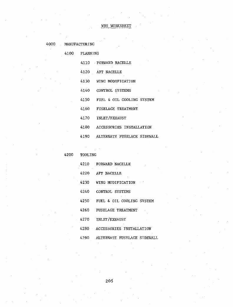
WBS WORKSHEET
4000 MANUFACTURING
4100 PLANNING
4110 FORWARD NACELLE
4120 AFT NACELLE
4130 WING MODIFICATION
4140 CONTROL SYSTEMS
4150 FUEL & OIL COOLING SYSTEM
4160 FUSELAGE TREATMENT
4170 INLET/EXHAUST
4180 ACCESSORIES INSTALLATION
4190 ALTERNATE FUSELAGE SIDEWALL
4200 TOOLING
4210 FORWARD NACELLE
4220 AFT NACELLE
4230 WING MODIFICATION
4240 CONTROL SYSTEMS
4250 FUEL & OIL COOLING SYSTEM
4260 FUSELAGE TREATMENT
4270 INLET/EXHAUST
4280 ACCESSORIES INSTALLATION
4290 ALTERNATE FUSELAGE SIDEWALL
205

WBS WORKSHEET
4000 MANUFACTURING (CONTINUED)
4300 FABRICATION
4310 FORWARD NACELLE
4320 AFT NACELLE
4330 WING MODIFICATION
4340 CONTROL SYSTEM
4350 FUEL & OIL COOLING SYSTEM
4360 FUSELAGE TREATMENT
4370 INLET EXHAUST
4380 ACCESSORIES INSTALLATION
4390 ALTERNATE FUSELAGE SIDEWALL
4400 ASSEMBLY
4410 FORWARD NACELLE
4420 AFT NACELLE
4500 AIRCRAFT MODIFICATION
4501 AIRCRAFT AVAILABILITY
4510 WING STRUCTURE
4520 FUEL SYSTEM
4530 SPOILER CONTROL SYSTEMS
4540 WING LEADING EDGE
206

WBS WORKSHEET
4000 MANUFACTURING (CONTINUED)
4600 INSTALLATION
4610 AFT NACELLE
4620 FORWARD NACELLE
4630 PROPULSION SYSTEM
4640 FUEL SYSTEM
4650 CONTROL SYSTEMS
4660 FUSELAGE TREATMENT
4670 INLET/EXHAUST
4680 ACCESSORIES
4690 ALTERNATE FUSELAGE SIDEWALL
4700 SUSTAINING ENGINEERING
207

WBS WORKSHEET
5000 GROUND TESTS
5100 INSTRUMENTATION
5110 DESIGN
5111 FORWARD NACELLE
5112 AFT NACELLE
5113 WING/FUSELAGE
5120 FABRICATION
5121 FORWARD NACELLE
5122 AFT NACELLE
5123 WING/FUSELAGE
5130 INSTALLATION
5131 FORWARD NACELLE
5132 AFT NACELLE
5133 WING/FUSELAGE
5200 TEST STAND
5210 TEST PLAN
5220 INSTALLATION - SUPPORT FIXTURE FORWARD NACELLE
5221 DESIGN
522101 TEST STRUCTURE 522102 CONTROLS 522103 FUEL SYSTEM
5222 FABRICATION
522201 TEST STRUCTURE 522202 CONTROLS 522203 FUEL SYSTEM
5223 ASSEMBLY TEST STRUCTURE
522301 TEST STRUCTURE 522302 CONTROLS 522303 FUEL SYSTEM
208

WBS WORKSHEET
5000 GROUND TESTS (CONTINUED)
5200 TEST STANDS (CONTINUED)
5224 TEST STAND INSTALLATION
522401 TEST STRUCTURE 522402 CONTROLS 522403 FUEL SYSTEM
5230 INSTRUMENTATION
5231 DESIGN
5232 FABRICATION
5233 INSTALLATION
5240 NACELLE INSTALLATION
5250 EQUIPMENT INSTALLATION
5251 ENGINE - GB - PROP
5252 CONTROLS
5253 FUEL SYSTEM
5254 ACCESSORIES
5260 STARTUP & CHECKOUT
5270 TEST RUNS
5280 DATA REDUCTION & ANALYSIS
5290 TEST REPORT
5300 GROUND VIBRATION TEST
5310 TEST PLAN
5320 TEST SETUP
5321 DESIGN
5322 FABRICATION
5323 ASSEMBLY
209

WBS WORKSHEET
5000 GROUND TESTS (CONTINUED)
5300 GROUND VIBRATION TEST (CONTINUED)
5400
5500
5330 INSTRUMENTATION
5331 DESIGN
5332 FABRICATION
5333 INSTRUMENTATION INSTALLATION
5340 AIRCRAFT SETUP
5350 TESTING
5360 DATA REDUCTION & ANALYSIS
5370 TEST REPORT
STATIC ENGINE RUN - INSTALLED
5410 TEST PLAN
5420 ENGINE STARTUP & CHECKOUT
5430 ENGINE TEST RUNS
5440 ACOUSTIC TEST RUNS
5441 ENGINE RUNUP ACOUSTIC TESTS
5442 CABIN REVERBERATION TESTS
5450 DATA REDUCTION & ANALYSIS
5460 TEST REPORT
TAXI TESTS
5510 TEST PLAN
5520 ENGINE TEST TAXI RUNS
5530 ACOUSTIC TEST TAXI RUNS
5540 DATA REDUCTION
5550 TEST REPORT
210

WBS WORKSHEET
5000 GROUND TESTS (CONTINUED)
5600 ALTERNATE FUSELAGE SIDEWALL
5610 TEST PLAN
5620 INSTRUMENTATION
5621 DESIGN
5622 FABRICATION
5623 INSTALLATION
5630 GROUND TESTS
5631 STATIC ENGINE RUNS
5632 TAXI RUNS
5640 DATA REDUCTION & ANALYSIS
5650 TEST REPORT
5700 SUSTAINING ENGINEERING
211

WBS WORKSHEET
OPTION PROGRAM
5800 FORWARD NACELLE 40 x 80
5810 TEST PLAN
5820 INSTRUMENTATION
5821 DESIGN
5822 FABRICATION
5823 INSTALLATION
5830 TEST INSTALLATION
5831 DESIGN
5832 FABRICATION
5833 INSTALLATION
5840 NACELLE INSTALLATION
5841 STRUCTURAL
5842 POWER SYSTEM
5843 CONTROLS
5844 FUEL SYSTEM
5850 CHECKOUT & STARTUP
5851 STATIC STARTUP
5852 TUNNEL RUN
5853 CHECKOUT RUN
5860 TEST RUNS
5870 DATA REDUCTION & ANALYSIS
5880 TEST REPORT
5900 NACELLE/WING 40 x 80
5910 TEST PLAN
212

WBS WORKSHEET
OPTION PROGRAM
5900 NACELLE/WING 40 x 80 (CONTINUED)
5920 INSTRUMENTATION
5921 DESIGN
5922 FABRICATION
5923 INSTALLATION
5930 TEST INSTALLATION
5931 DESIGN
5932 FABRICATION
5933 INSTALLATION
5940 TEST WING INSTALLATION
5941 MODIFICATION DESIGN
5942 FABRICATION
5943 WING MODIFICATION
5944 INSTALLATION
5945 AFT NACELLE INSTALLATION
5950 NACELLE INSTALLATION
5951 STRUCTURAL
5952 POWER SYSTEM
5953 CONTROLS
5954 FUEL SYSTEM
5960 CHECKOUT & STARTUP
5961 STATIC STARTUP
5962 TUNNEL RUN
5963 CHECKOUT RUN
5970 TEST RUNS
5980 DATA REDUCTION & ANALYSIS
5990 TEST REPORT
213

WBS WORKSHEET
6000 FLIGHT TESTS
6100 TEST PLAN
6110 FLIGHT SAFETY REVIEW BOARD
6120 FIRST FLIGHT
6200 INSTRUMENTATION CHECKOUT
6300 AIRCRAFT ENVELOPE EVALUATION
6310 FLUTTER CHECKS
6320 STABILITY & CONTROL
6330 BUFFET BOUNDARY
6400 TEST ENGINE OPERATION
6410 INFLIGHT STARTUP
6420 POWER VARIATIONS
6500 ENGINE TEST ENVELOPE EVALUATION
6510 HIGH SPEED
6520 LOW SPEED
6530 APPROACH CONFIGURATION
6600 PERFORMANCE TESTS
6610 DISK LOADING VARIATION
6620 SPEED VARIATIONS
6700 ACOUSTIC TESTS
6710 CRUISE CONDITION
6720 LOW SPEED
6730 APPROACH CONFIGURATION
214
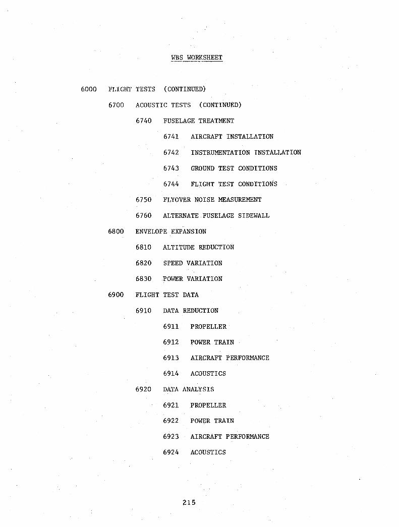
6000
WBS WORKSHEET
FLIGHT TESTS (CONTINUED)
6700
6800
6900
ACOUSTIC TESTS (CONTINUED)
6740 FUSELAGE TREATMENT
6741 AIRCRAFT INSTALLATION
6742 INSTRUMENTATION INSTALLATION
6743 GROUND TEST CONDITIONS
6744 FLIGHT TEST CONDITIONS
6750 FLYOVER NOISE MEASUREMENT
6760 ALTERNATE FUSELAGE SIDEWALL
ENVELOPE EXPANSION
6810 ALTITUDE REDUCTION
6820 SPEED VARIATION
6830 POWER VARIATION
FLIGHT TEST DATA
6910 DATA REDUCTION
6911 PROPELLER
6912 POWER TRAIN
6913 AIRCRAFT PERFORMANCE
6914 ACOUSTICS
6920 DATA ANALYSIS
6921 PROPELLER
6922 POWER TRAIN
6923 AIRCRAFT PERFORMANCE
6924 ACOUSTICS
215

WBS WORKSHEET
6000 FLIGHT TESTS (CONTINUED)
6900 FLIGHT TEST DATA (CONTINUED)
6930 TEST REPORTS
6931 PROPELLER
6932 POWER TRAIN
6933 AIRCRAFT PERFORMANCE
6934 ACOUSTICS
6940 ALTERNATE FUSELAGE SIDEWALL
6941 DATA REDUCTION
6942 DATA ANALYSIS
6943 TEST REPORT
7000 BASELINE FLIGHT TESTS
7100 TEST PLAN
7200 CALIBRATE ENGINES
7300 INSTRUMENTATION (DATA SYSTEM)
7310 DESIGN
7320 FABRICATION
7330 INSTALLATION
7400 WING PRESSURE SURVEY
7500 CRUISE PERFORMANCE
7600 FLIGHT TEST DATA
7610 DATA REDUCTION
7620 DATA ANALYSIS
7630 TEST REPORT
216

WBS WORKSHEET
8000 MAJOR SUBCONTRACTS
9000
DETROIT DIESEL ALLISON - ENGINE
- GEARBOX
HAMILTON STANDARD - PROPELLER
- NACELLE
PROGRAM MANAGEMENT
9100 PROJECT MANAGEMENT
9200 ADMINSTRATION BUDGET/SCHEDULE
9300 REPORTING - PERIODIC
9400 ORAL BRIEFINGS
9401 NO. 1 ANNUAL
9402 NO. 2 ANNUAL
9403 NO. 3 ANNUAL
9404 NO. 4 ANNUAL
9405 FINAL ORAL
9500 INTERIM REPORT
9600 FINAL & SUMMARY REPORT
9700 TRAVEL
217

This Page Intentionally left Blank

= >< c ;;;;:: W Q.. Q..
c(
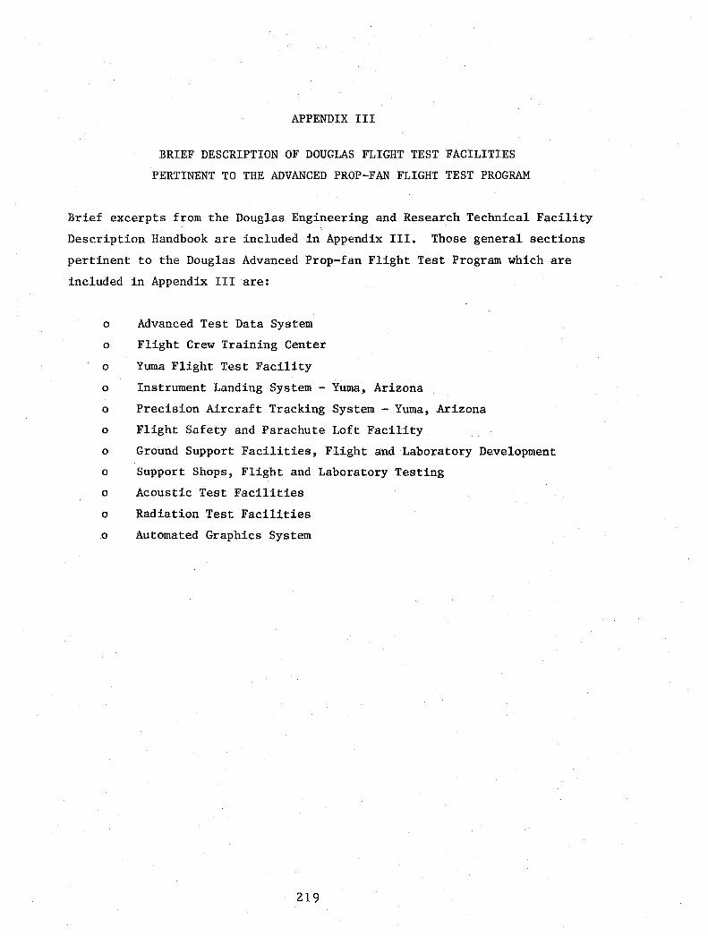
APPENDIX III
BRIEF DESCRIPTION OF DOUGLAS FLIGHT TEST FACILITIES
PERTINENT TO THE ADVANCED PROP-FAN FLIGHT TEST PROGRAM
Brief excerpts from the Douglas Engineering and Research Technical Facility
Description Handbook are included in Appendix III. Those general sections
pertinent to the Douglas Advanced Prop-fan Flight Test Program which are
included in Appendix III are:
o Advanced Test Data System
o Flight Crew Training Center
o Yuma Flight Test Facility
o Instrument Landing System - Yuma, Arizona
o Precision Aircraft Tracking System - Yuma, Arizona
o Flight Safety and Parachute Loft Facility
o Ground Support Facilities, Flight and Laboratory Development
o Support Shops, Flight and Laboratory Testing
o Acoustic Test Facilities
o Radiation Test Facilities
o Automated Graphics System
219

This Page Intentionally Left Blank

DOUGLAS AIRCRAFT CONfPANY
/' MCDONNELL DOUGL~
CORPORATION
ENGINEERING AND RESEARCH TECHNICAL FACILITY DESCRIPTION
ADVANCED TEST DATA SYSTEM
The Douglas Flight Test Data System was designed to provide a new approach to data acquisition, communications, and processing. To ensure success for the DC-l0 Program, these three elements were developed and integrated simultaneously to obtain maximum compatibility. The resulting system has performed very well and according to design specifications. It has been successfully utilized in the development and certification of the DC- 1 0 (Series 10, 30, and 40), DC-9 and DC-8 commercial aircraft, the A-4N military attack aircraft and the YC-15 advanced medium STOL transport development and demonstration programs, and many miscellaneous laboratory programs, including seat ejection development tests and fuselage decompression tests.
Operational Characteristics:
Airborne Data Acquisition System The airborne data acquisition system was procured in 1968 and 10 of these systems are in use today. The system uses Pulse Code Modulation (PCM) encoding techniques and contains 400 data channels, 90 channels recorded at prime sampling rates, 290 channels recorded at a 10: 1 subcom rate, and 20 channels 20: 1 at a subcom rate. The prime and subcom allocations are made up of 320 analog, 60 digital, and 20 frequency input channels. This prime channel sampling srate can be controlled in flight from 400 to 10 samples per second in 6 stages.
Test information is resolved into a 10-bit data word for a ±511-count range. The maximum data stream rate is 500,000 bits per second. Recording is in a manchester 1 code (serial) with a maximum tape packing density of 8333 bits per inch. Telemetry transmission uses Non Return to Zero (NRZ) -M code. An IR IG time code generator is integrated in the system to provide system clock, remote time displays for the flight-test engineer, clocking pulses to drive auxiliary equipment, group binary time in the data stream, and serial Binary Coded Decimal (BCD) time with a l-kHz carrier on a separate tape search track.
The system is given wide flexibility for recording instrumentation inputs through the use of a signal conditioning subsystem. This subsystem consists of an identical processing network for 320 analog input channels packaged in two 160-channel modules. Each
REVISEO NQVEMBER 1979
221
one provides amplification (gain), zero adjustment, active filtering, common mode isolation, shunt calibration, and standard instrumentation excitation power distribution. All elements except amplifiers may be bypassed if desired. Transducer bridge, thermocouple, or other electrical signal inputs of 5 millivolts to 30 volts full-scale can be accepted on any of these universal analog channels. In addition, the system will accept pure parallel digital inputs on both prime and subcom channels.
In the testing of the relatively small A-4N military aircraft, a special small airborne data acquisition system was developed. This Mini System (125 channels) is a subset of the larger 400 Channel System and was installed in a l50-gallon external store for the A-4N test project.
Multiplexer Airborne System This is an advanced airborne acquisition system using a centr,,1 programmable controller for the selection and formatting of the PCM data stream from small remotely located acquisition units. These remote multiplexer units are mounted in various areas of the test aircraft, such as in the wing, engines, the avionics compartment, the tail section, etc., and connected to the central controller by a single cable from each unit. Each remote unit uses large-scale integrated (LSI) solid-state electronics to produce a very small size, but rei iable package. The cost of installing miles of wiring and the associated man-hours in a standard instrumented aircraft are eliminated by this decentralized remote multiplexer acquisition system. All airborne data systems have a l4-track tape recorder with 2-MHz bandwidth response at a tape speed of 120 inches per second. The recorders operate at anyone of six run speeds to match the selected digital data sampling rates. The PCM data are recorded on one track and the IRIG B on another. The magnetic tape, which is 1 inch wide, has 12 other tracks for FM or other data recording (Figure 1).
FACILITY LOCATION IDEPTNO. 257 I BLDG NO.
41A CITY I STATE Long BeaCh California
220-00'-'

FIGURE 1. FLIGHT RECORDER ONBOARD
Data Transmission/Communications Developed and procured at the same time as the airborne acquisition systems was the baseline telemetry and microwave link that provides real-time data and voice communications for Douglas flight test operations in Southern California. The telemetry section originally utilized dual, 10-watt, L-band transmitters in the aircraft operating on different frequencies in the 1435- to 1485-MHz band. An automated ground
tracking antenna is located atop the 8400-foot Blue Ridge Electronics Site, Figure 2 (42 air miles from Long Beach) and provides a test radius of up to 250 miles at 30,000-foot altitude. The mountain-top facility uses four receivers for frequency and polarization diversity monitoring of signals to minimize signal dropout during aircraft maneuvering. The entire data stream and I RIG time of day is received and relayed to Long Beach via the microwave link and also provides active radio communication on several bands between test ai rcraft and the Long Beach faci I ity. Automatic microwave fault isolation monitoring is also carried on the link (Figure 2).
FIGURE 2. BLUE RIDGE TELEMETRY STATION
REVISED NOVEMBER 1979
222
New Facilities and Capabilities
\" \
\
The following improvements have been made in the T/M microwave link: (1) Telemetry Transmission -One of the earliest updates to the telemetry section was to improve the reliability and bandwidth capa
bilities of the airborne transmitter; 20-watt transmitters have replaced the 10-watt units and have improved the overall operation considerably. (2) Yuma Remote Terminal - Shortly after the start of the DC-10 test program the bulk of the test operation was moved to Yuma, Arizona, which is 190 air miles from Long Beach. Initially, test flights from this facility were monitored with telemetry from the Blue Ridge antenna only after the aircraft had reached an altitude of 20,000 feet. Today the operation is quite different. The Yuma facility has its own telemetry tracking system and is connected to Long Beach by a separate microwave system, using four automatic relay stations. This greatly extended system now covers airspace from above Fresno, California, into Baja, California where the Mexican Government has given Douglas Aircraft permission to operate (Figure 3). (3) Data Dump - Operating from
\
SAN FRANCISCO • NEVADA
~--
"-
~ "' /' "-/ ,
I • FRESNO I
~
"- ....... ...... ....
UTAH
\ ARIZONA \...,
"-, • \
\ \
r - .-I I l. .... TUCSON
FIGURE 3. DATA TRANSMISSION LINKAGE
Yuma necessitated an improvement in the transportation of high-priority airborne recorded tapes to the Long Beach facility. Instead of waiting for air or ground shipment of these tapes they are now dumped via the microwave link to Long Beach and duplicateu on similar tape equipment. Playback rates of up to 1 MHz are used to expedite this transmittal providing a speed up to 2 to 64 times the real-time record rate. (4) Closed Circuit TV - The Yuma microwave link provides 24 channels of telephone lines in addition to the data transmittal. Management and engineering personnel at Long Beach and their counterpart at Yuma now communicate (pre- and post-flight meetings, etc.) from conference rooms and offices
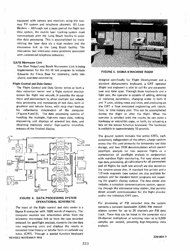
equipped with camera and monitors using the twoway TV system and telephone channels. (5) Laser Modem - Although not a basic part of the flight test data system, the mobile laser tracking system must communicate with the Long Beach facility to expedite data processing. This is accomplished by transmitting the laser data via a dual modem and the microwave link to the Long Beach facility. The microwave link eliminates many problems associated with commercial telephone networks.
EAFB Microwave Link The Blue Ridge/Long Beach Microwave Link is being implemented for the KC- 1 0 test program to include Edwards Air Force Base for telemetry, radio tele· phone, and data monitoring.
Flight Control and Data Center The Flight Control and Data Center serves as both a data reduction center and a flight control monitor station for flight test aircraft. It provides the equipment and environment to allow multiple test vehicle data processing and monitoring of test data, both in graphical and tabular forms, with strip chart backup for redundancy independent of the computer (Figures 4 and 5). The data processing consists of handling the multiple, high-rate input data, making engineering unit displays of selected test data, and obtaining hardcopy and/or high-quality microfilm outputs of the finished display.
TAPE~ PLAylQj KEYBOARD
SPECIAL ANAL VSIS TAPE
FIGURE 4. DATA PROCESSING SYSTEM OPERATIONAL SCHEMATIC
The heart of the flight control and data center is a Sigma 9 computer with 192K words of memory. The computer receives test information either from the telemetry microwave link or from the tape recorded onboard for postflight analysis, converts the raw data into engineering units and displays the results in corrected time history or tabular form on cathode ray tubes (CRT). Through a special function keyboard
REVISED NOVEMBER 1979
223
FIGURE 5. SIGMA 9 MACHINE ROOM
designed specifically for Flight Development and a standard alphanumeric keyboard, a CRT operator (flight test engineer) is able to call for any parameter over any time span. Through these keyboards and a light pen, the operator is capable of adding, deleting or replacing parameters, changing scales in both X and Y axes, adding notes and titles, and producing on the CRT a final annotated engineering unit tabulation, or time history plot. This can be accomplished during the flight or after the flight. When the operator is satisfied with the results, he can make a hardcopy or microfilm copy, or both, by actuating a key on the special function keyboard. The hardcopy is available in approximately 10 seconds.
The ground system includes five active CRTs, each completely independent of the others, a large random access disc file used primarily for temporary raw data storage, and two J;lCM decommutators which permit postflight analysis on two separate flights or a combination of postflight analysis in conjunction with real-time flight monitoring. For easy access and fast data processing, all calibrations for all parameters
and all flights for each test aircraft are also stored on the random-access disc. A standard line printer and a 1/2-inch magnetic tape output are also available for analysis and for standard batch programs not requiring the graphic display output. The data center also includes a complete communications system, operating through the microwave relay station, that permits direct aircraft communication for the flight director and/or the individual CRT users.
For processing of FM recorded data the system contains a constant bandwidth (CBW) FM demodulation system for up to 20 channels per FM data track. These data can be input to the computer via a 24-channel multiplexer at sampling rates up to 8,000 samples per second, providing high-frequency data analysis.
220-001-3

Associated Equipment: (Figures 4, 5, and 6)
Sigma 9 computer (192K memory bank) PCM decommutators 24-channel multiplexer
Constant bandwidth discriminator rack 3 Sigma 2 computers (32K memory bank)
Card readers Card punch Five 9-track computer tape units - 800 BPI Four 9-track computer tape units - 800/1600 BPI Three 14-track tape recorders Fourteen rapid access discs (RADS), 6.2 million bytes each Two teletype writers
Three line printers Five display generators
Six Sanders CRT display units Two hardcopy units
Microfilm unit Telemetry input rack
REVISED NOVEMBER 1979 224
Laser receiver modem rack Radio communications console
FIGURE 6. FLIGHT TEST CONTROL ROOM
220-001-4
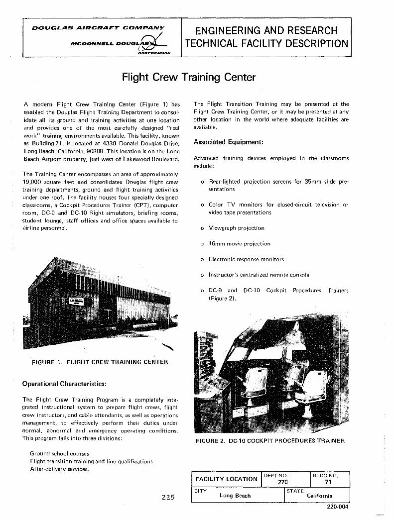
DOUGLAS AIRCRAFT COMPANY /
MCDONNELL DOUGL~ CORPORATION
ENGINEERING AND RESEARCH TECHNICAL FACILITY DESCRIPTION
Flight Crew Training Center
A modern Flight Crew Training Center (Figure 1) has
enabled the Douglas Flight Training Department to consol
idate all its ground and training activities at one location and provides one of the most carefully designed "real
work" training environments available_ This facility, known as Building 71, is located at 4330 Donald Douglas Drive,
Long Beach, California, 90808. This location is on the Long Beach Airport property, just west of Lakewood Boulevard.
The Training Center encompasses an area of approximately 19,000 square feet and consolidates Douglas fl ight crew training departments, ground and flight training activities under one roof. The facility houses four specially designed classrooms, a Cockpit Procedures Trainer (CPT), computer room, DC-9 and DC-10 flight simulators, briefing rooms, student lounge, staff offices and office spaces available to airline personnel.
FIGURE 1. FLIGHT CREW TRAINING CENTER
Operational Characteristics:
The Flight Crew Training Program is a completely integrated instructional system to prepare flight crews, flight
crew instructors, and cabin attendants, as well as operations
management, to effectively perform their duties under normal, abnormal and emergency operating conditions. This program falls into three divisions:
Ground school courses Flight transition training and line qualifications After-delivery. services.
225
The Flight Transition Training may be presented at the Flight Crew Training Center, or it may be presented at any other location in the world where adequate facilities are available.
Associated Equipment:
Advanced training devices employed in the classrooms include:
o Rear-lighted projection screens for 35mm slide presentations
o Color TV monitors for closed-circuit television or video tape presentations
o Viewgraph projection
o 16mm movie projection
o Electronic response monitors
o Instructor's centralized remote console
o DC-9 and DC-lO Cockpit Procedures Trainers (Figure 2).
FIGURE 2_ DC-10 COCKPIT PROCEDURES TRAINER
FACILITY LOCATION \ DEPT NO. 270
CITY \ STATE Long Beach
\
BLDG NO. 71
California
220-004
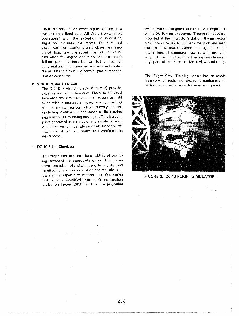
These trainers are an exact replica of the crew stations on a fixed base. All aircraft systems are operational with the exception of navigation, flight and air data instruments. The aural and visual warnings, cautions, annunciators and associated logic are operational, as well as sound simulation for engine operation. An instructor's failure panel is included so that all normal,
abnormal and emergency procedures may be introduced. Design flexibility permits partial reconfig
uration capability.
o Vital III Visual Simulator The DC-10 Flight Simulator (Figure 3) provides
visual as well as motion cues. The Vital III visual simulator provides a realistic and responsive night scene with a textured runway, runway markings
and numerals, horizon glow, runway lighting (including VASI's) and thousands of light points
representing surrounding city lights. This is a com
puter generated scene providing unlimited maneuverability over a large volume of air space and the flexibility of program central to reconfigure the
visual scene.
o DC-1O Flight Simulator
This flight simulator has the capability of providing advanced six-degrees-of-motion. This move
ment provides roll, pitch, yaw, heave, slip and
longitudinal motion simulation for realistic pilot
training in response to motion cues. One design feature is a simplified instructor's malfunction projection layout (SIMPL). This is a projection
226
system with backlighted slides that will depict 24
of the DC-1O's major systems. Through a keyboard mounted at the instructor's station, the instructor
may introduce up to 53 separate problems into each of these major systems. Through the simu
lator's integral computer system, a record and playback feature allows the training crew to recall any part of an exercise for review and study.
The Flight Crew Training Center has an ample inventory of tools and electronic equipment to
perform any maintenance that may be required.
FIGURE 3. DC-10 FLIGHT SIMULATOR

DOUGLAS AIRCRAFT COItIIPANY
/
MCDONNELL DOUGL~ CORPORATION
ENGINEERING AND RESEARCH TECHNICAL FACILITY DESCRIPTION
Yuma Flight Test Facility
The Douglas Aircraft Company operates a modern Flight Test Facility (C3) (Figure 1), located adjacent to the Yuma International Airport, Yuma, Arizona, which is specifically designated to support Douglas Aircraft Development Programs. This facility has direct access to the airport proper. The main runway (3L-21 R) is 13,300 feet long by 200 feet wide. The test facility encompasses a total area of 46.2 acres, of which approximately 22 acres have been developed. The entire area is on a 20-year leasehold contracted with the Yuma Airport Authority beginning in 1969. The advantages of the Yuma Test Facility became obvious during the first phase of the DC-1O Test Program. Good flying weather, uncongested airspace, ready access to the Mexican corridor, and close proximity to the city of Yuma combined to permit unprecedented efficiency in testing operations.
Operational Characteristics:
Operations The test site operations are housed in a block wall constructed building 60 by 70 feet comprising the facility management offices, flight test engineering office, flight dispatch radio room, photography/ oscillograph darkroom, conference rooms, and the necessary restrooms. I n add ition, there is a 40- by 60-foot trailer for additional office space use.
Support Building This is a 6,000-square-foot (60- by 100-foot) metal constructed building that houses the operations support offices and shop area. The entire building is environmentally controlled.
FIGURE 1. AERIAL VIEW - DAC FLIl:iHT TES I FACILITY AT YUMA, ARIZONA
227
FACILITY LOCATION jDEPT NO. 270
CITY .\ STATE Yuma
\
BLDG NO. 300,301
Arizona
220-012
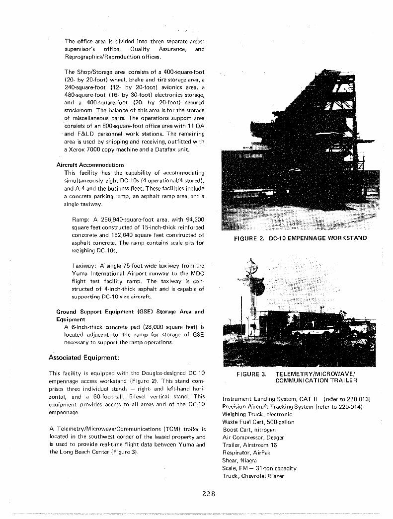
The office area is divided into three separate areas: supervisor's office, Quality Assurance, and Reprographics/Reproduction offices.
The Shop/Storage area consists of a 400-square-foot (20- by 20-foot) wheel, brake and tire storage area, a 240-square-foot (12- by 20-foot) avionics area, a 480-square-foot (16- by 30-foot) electronics storage, and a 400-square-foot (20- by 20-foot) secured stockroom. The balance of this area is for the storage of miscellaneous parts. The operations support area consists of an 800-square-foot office area with 11 QA and F&LD personnel work stations. The remaining area is used by shipping and receiving, outfitted with a Xerox 7000 copy machine and a Datafax unit.
Aircraft Accommodations This facility has the capability of accommodating simultaneously eight DC-1Os (4 operational/4 stored), and AA and the business fleet. These facilities include a concrete parking ramp, an asphalt ramp area, and a single taxiway.
Ramp: A 256,940-square-foot area, with 94,300 square feet constructed of 15-inch-thick reinforced concerete and 162,640 square feet constructed of asphalt concrete. The ramp contains scale pits for weighing DC-10s.
Taxiway: A single 75-foot-wide taxiway from the Yuma I nternational Airport runway to the MDC flight test facility ramp. The taxiway is constructed of 4-inch-thick asphalt and is capable of supporting DC-10 size aircraft.
Ground Support Equipment (GSE) Storage Area and Equipment
A 6-inch-thick concrete pad (28,000 square feet) is located adjacent to the ramp for storage of GSE necessary to support the ramp operations.
Associated Equipment:
This facility is equipped with the Douglas-designed DC-10 empennage access workstand (Figure 2). This stand comprises three individual stands - right- and left-hand horizontal, and a 60-foot-tall, 5-level vertical stand. This equ ipment provides access to all areas and of the DC-10 empennage.
A Telemetry/Microwave/Communications (TCM) trailer is located in the southwest corner of the leased property and is used to provide real-time flight data between Yuma and the Long Beach Center (Figure 3).
228
FIGURE 2. DC-10 EMPENNAGE WORKSTAND
FIGURE 3. TELEMETRY/MICROWAVE/ COMMUNICATION TRAILER
Instrument Landing System, CAT II (refer to 220-013) Precision Aircraft Tracking System (refer to 220-014) Weighing Truck, electronic Waste Fuel Cart, 500-gallon Boost Cart, nitrogen Air Compressor, Deager Trailer, Airstream 16 Respirator, AirPak Shear, Niagra Scale, FM - 31-ton capacity Truck, Chevrolet Blazer

Two Skydrol Test Stands, 30-gpm Sprague Two workstands, Skywitch Two power unit 99-kva tractors Clarktor tug, 6-wheel, outfitted with rigging level sensor Four Skydrol test stands, 50-gpm Sprague Two aircraft movers Two axle jacks, 60-ton, Malabar Two axle jacks, 60-ton, Sangor Cryostart unit, for aircraft starting Trailer data - 40-foot Trailer, American photo Testok, air data Truck, Ford Skyworker
Four workstands, Ballymore Power unit, 60-kva diesel Two Ground Starter Units, air portable (MAlA) Water waste cart Level Sensor Readout Module, Kearfott A/C unit, 3-ton Ale unit, 30-ton Cargo loader Aerostand, 24-foot
In addition, the ground support operations has ample shop and electronic equipment to support the everyday operations.
Support Facilities Two 20,000-galion fuel tanks Two 1 ,500-gallon sewage disposal units Deionized water, 36,000-gallon capacity 1,000-kva minimum, 1,700-kva at 2,000 amperes,
electrical transformer to supply the existing facilities
Liquid nitrogen storage area 1,500-gallon gasoline supply for ground support
vehicles Power islands, 440 volts
Telephone Communications
229
Direct dial tielines on the voice network have been provided to give direct access to and from telephone stations at the Yuma Facility via the DAC Microwave Link.

DOUGLAS AIRCRAFT COItIIPANY
/
MCDONNELL DOUGL~ CORPORATION
ENGINEERING AND RESEARCH TECHNICAL FACILITY DESCRIPTION
Instrument Landing System - Yuma, Arizona
A Douglas-owned, single-channel, solid-state Airborne Instru ments Laboratory (Cutler-Hammer) Type 55 L I nstrument Landing System (tLS) is installed at the Yuma, Arizona, airport on Runway 3L. There are three transmitters: the glideslope, localizer, and the middle marker. The glideslope antenna is 40 feet west and 1250 feet from the end of the runway (Figure 1).
FIGURE 1. ILS GLiDESLOPE TRANSMITTER
The local izer antenna is 10 feet high and is located 900 feet off the runway on a runway centerline (Figure 2).
Applications:
The ILS system was purchased and installed by Douglas to
support DC-10 CAT II, III Autoland development, DC-9/10 production acceptance and test flight checks, and customer
flight training activities at Yuma. Figure 3 illustrates the physical location of the localizer and glideslope trans
mitters. Figure 4 illustrates the beam geometry of the Category II I nstrument Landing System.
FIGURE 2. ILS LOCALIZER TRANSMITTER
I DEPT [\,l0. I BLllGJ'ill. FACILITY LOCATION 270 YUnlar"nt'fATrport
230 CITY Yuma I STATE-~~------220-013

DOUGLAS AIRCRAFT COMPANY
/
MCDONNELL DOUGL~ CORPORATION
ENGINEERING AND RESEARCH TECHNICAL FACILITY DESCRIPTION
Precision Aircraft Tracking System, Yuma, Arizona
Douglas has introduced a Precision Aircraft Tracking System (PATS) or optical radar. It was developed primarily for aircraft instrument landing system tests, flyover noise tests, and other tasks which require very accurate flight path determination.
Operational Characteristics:
During normal operation, the Tracker determines the azimuth, elevation, and range of the target at a sample rate of 100 measurements per second. These data are timecorrelated via a precision time-code generator, periodically checked against a time standard. These measurements plus time of day are available as binary words for data recording on magnetic tape and are directly displayed for immediate reference. The magnetic tape "is processed in the F&LD Data Center to yield final data. This system eliminates the need for reduction of data from photographic or radio theodolite systems.
A single operator is required for the acquisition function, and tracking is automatically initiated when the target is positioned in the acquisition field. An infrared vidicon is used for acquisition and provides haze penetration and sensitivity to the infrared laser radiation.
The Precision Laser Tracker consists of an infrared laser transmitter, a laser pulse receiver, an infrared television camera and TV monitor for the operator and a servocontrolled mirror mount. A retroreflector is mounted on the aircraft to provide adequate return signal to the Tracker, and to define the tracking point precisely. The transmitter consists of a Q-switched, flash-pumped Nd: Yag Laser operating at 100 pps. The 1.06-microradiation is not visible or hazardous to the test aircraft crew.
The Tracker is mounted in a van, as shown in Figure 1, and the laser beam is transmitted and received through the servo-controlled mirror. The television camera receives an ambient image of the target and the surrounding field of view.
The laser pulse receiver generates range data and angle errors for the servo-controlled mirror. The return of a pulse by the retroreflector automatically initiates tracking. The system then tracks automatically and no further manual control is required (Figure 2).
System Features:
Self-contained mobile system (auxiliary power unit
231
required)
I nfrared TV used for initial acquisition Autotrack from 1000 to 60,000 feet Azimuth, elevation, range, and time recorded at 1, 10, or
100 samples/second Data recorded on computer-compatible magnetic tape Precision time code referenced to WWV Solid state 1060 Angstrom laser (Neodynium-Doped
Yttrium Aluminum Garnet) Automatic control of laser power for eye safety System performance
FIGURE 1. LASER VAr ..
TRAN~MITTEII RECEIVER
.~-+-----------
FIGURE 2. SYSTEM BLOCK DIAGRAM
Range Azimuth
Resolution
±0.5 Ft ±0.1 Milliradian
Estimated Accuracy Target Range
10,000 Ft
x Y
Elevation ±0.2 Milliradian Z
±3 Ft ±2 Ft ±3 Ft
Time ±0.1 M illisec
FACILITY LOCATION 1 DEPT;7~ CITY 1 STATE
Yuma
IBLDG NO.
Ramp
Arizona
220-014

DOUGLAS AIRCRAFT COItIIPANY
/ MCDONNELL DOUGL~
CORPORATION
ENGINEERING AND RESEARCH TECHNICAL FACILITY DESCRIPTION
Flight Safety and Parachute Loft Facility
The Flight and Laboratory Development Division (F&LD)
of the Douglas Aircraft Company maintains a facility which
is made up of the flight safety group, FAA Repair Station (No. 4108) and a flight equipment issue room. The flight
safety group and FAA Repair Station are located in the parachute loft (Figure 1) which has about 1900 square feet of floor space and provides housing and space for mainte
nance and storage of survival equipment associated with
commercial and military flight.
FIGURE 1. PARACHUTE LOFT
Operational Characteristics:
The parachute loft is responsible for al! inspection and certification of production and development work per
formed within the Douglas Aircraft Company on the
following listed equipment:
Parachutes
Life Rafts Life Vests Escape Slides
Survival Kits
Helmets
Flight Clothing
232
In addition, the personnel staffing this facility and the FAA
Repair Station are certified as master parachute riggers and
repairmen of emergency equipment.
Associated Equipment:
A room 10 by 10 feet with a ceiling 60 feet high used for
airing and drying parachute canopies.
Parachute packing table 50 feet long, used for inspection,
repair, and repacking of personnel parachutes, and drag and
spin chutes.
A carpeted area approximately 17 by 25 feet used for inflation test inspection and repacking of life rafts and
escape sl ides.
Four sewing machines used in the repair and maintenance of all types of survival equipment and flight clothing.
A table 12 by 12 feet used for inspection and repair of
survival kits, life vest and fabric layout and cutting.
A complete technical library on. Navy, Air Force and
commercial safety and survival equipment.
All small tools required to repair and test safety equipment.
The Issue Room is located on the ground floor of F&LD
Flight Operations and has approximately 1400 square feet of floor space. Included in this facility are the following items:
A locker room with 96 flight crew members' lockers.
Lounge area for crew members.
Flight equipment issue room with storage space for 60
parachutes, a supply of flight clothing (flight suits,
jackets, boots, life vests and helmets).
FACILITY LOCATION IDEPTNO" 270
I STATE CITY Long Beach
I BLDG NO. 15
California
220-006
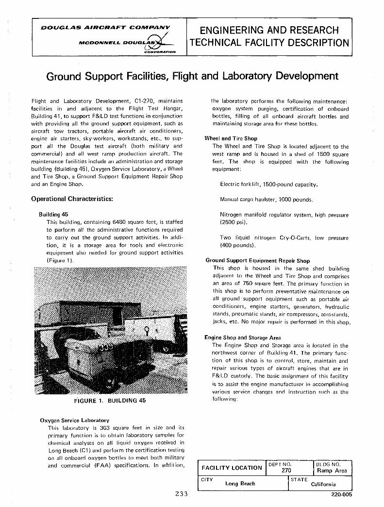
DOUGLAS AIRCRAFT COMPANY /
MCDONNEL.L. DOUGL.~ CORPORATION
ENGINEERING AND RESEARCH TECHNICAL FACILITY DESCRIPTION
Ground Support Facilities, Flight and Laboratory Development
Flight and Laboratory Development, Cl-270, maintains facilities in and adjacent to the Flight Test Hangar, Building 41, to support F&LD test functions in conjunction with providing all the ground support equipment, such as aircraft tow tractors, portable aircraft air conditioners, engine air starters, sky-workers, workstands, etc., to support all the Douglas test aircraft (both military and
commercial) and all west ramp production aircraft. The maintenance facilities include an administration and storage building (Building 45), Oxygen Service Laboratory, a Wheel and Tire Shop, a Ground Support Equipment Repair Shop and an Engine Shop.
Operational Characteristics:
Building 45 This building, containing 6480 square feet, is staffed
to perform all the administrative functions required to carry out the ground support activities. In addi
tion, it is a storage area for tools and electronic equipment also needed for ground support activities (Figure 1).
FIGURE 1. BUILDING 45
Oxygen Service Laboratory This laboratory is 363 square feet in size and its primary function is to obtain laboratory samples for chemical analyses on all liquid oxygen received in Long Beach (Cl) and perform the certification testing on all onboard oxygen bottles to meet both military and commercial (FAA) specifications. In addition,
233
the laboratory performs the following maintenance: oxygen system purging, certification of onboard bottles, filling of all onboard aircraft bottles and maintaining storage area for these bottles.
Wheel and Tire Shop
The Wheel and Tire Shop is located adjacent to the
west ramp and is housed in a shed of 1500 square feet. The shop is equipped with the following equipment:
Electric forklift, 1500-pound capacity.
Manual cargo haulster, 1000 pounds.
Nitrogen manifold regulator system, high pressure (2500 psi).
Two liquid nitrogen Cry-a-Carts, low pressure (400 pounds).
Ground Support Equipment Repair Shop
This shop is housed in the same shed building adjacent to the Wheel and Tire Shop and comprises an area of 750 square feet. The primary function in
this shop is to perform preventative m'aintenance on all ground' support equipment such as portable air conditioners, engine starters, generators, hydraulic stands, pneumatic stands, air compressors, aerostands, jacks, etc. No major repair is performed in this shop.
Engine Shop and Storage Area
The Engine Shop and Storage area is located in the northwest corner of Building 41. The primary func
tion of this shop is to control, store, maintain and repair various types of aircraft engines that are in
F& LD custody. The basic assignment of th is faci lity
is to assist the engine manufacturer in accomplishing various service changes and instruction such as the following:
FACI LlTY LOCATION 1 DEPT ;7~ CITY JSTATE
Long Beach
l BLDG NO. Ramp Area
California
220-005

Installation of test equipment.
Quick engine change build·up and replacement.
Installation and replacement of the auxiliary power unit (APU).
Installation and maintenance of nose cowl inlets.
Perform internal inspection of engines (Boroscope).
234
Maintenance of thrust reversers.
Preservation of engines.
Receiving and shipping of all F&LD engines and engine components.
Maintain current inventory and status of engines.

DOUGLAS AIRCRAFT CONIPANY
/
MCDONNELL DOUGL~ CORPORATION
ENGINEERING AND RESEARCH TECHNICAL FACILITY DESCRIPTION
SUPPORT SHOPS. FLIGHT AND LABORATORY TESTING
Several mechanical fabrication shops support Engineering Flight and Laboratory Testing. These shops have been
combined Into one facility so that maximum utilization of equipment and manpower can be achieved. With their diversified capability, a wide variety of unique products can
be produced from many materials to support engineering tests.
Typical products which are routine for this facility are precision models for wind tunnel and display, mockups of both plastic and wood, machined parts, sheet metal assemblies, and fabricated test fixtures.
Operational Characteristics:
Model Shop (Figures 1 and 2)
A completely equipped and staffed model shop can produce highly accurate metal scale models fully
instrumented for wind tunnel testing. Also, aesthetic display scale models are created by skilled personnel
for various purposes. The shops are nearly self· supporting except for special processing such as plating, heat treat, etc.
FIGURE 1. WIND TUNNEL MODEL
Machine Shop (Figure 3)
The Machine Shop consists of converntional machine tools and is staffed with a group of highly skilled personnel. This group specializes in developing new machining and fabricating techniques, machining
REVISED NOVEMBER 1979
235
FIGURE 2. MODEL SHOP
parts from new alloys for test purposes and providing unique and special parts in support of test programs.
The equipment consi sts of eight precision lathes ranging from tool room lathes to machines with a
swing of 22 inches in diameter by 102 inches in length. One 22-inch lathe is equipped with a full
length tracing attachment which has a 6-inch radial travel. There are ten milling machines: five universal,
two horizontal and three vertical. These machines are of various sizes having maximum table length of 60 inches. All equipment is completely tooled with supporting equipment so that any machining operation can be accomplished. A horizontal boring mill,
with a horizontal and vertical travel of 60 inches is available and completely tooled. Supporting tools
such as cylindrical and surface grinders, drill presses (radial, multiple and single spindle), cutoff saws, etc.,
all complement this shop (Figure 3).
Associated Machine Shop Equipment Includes: Numerically-controlled 3-axis mill 24- by 96-inch bed with an acramatic scanner with its own minicomputer. The scanner can be used as a conventional tracer or it can produce its own tapes by scanning a
part that needs to be duplicated. Another advantage of the scanner, as weighed against a tracer-controlled
FACILITY LOCATION I DEPT ;5~ CITY I STATE
Long Beach
1 BLDG NO. 26,32,41A
California
220-007
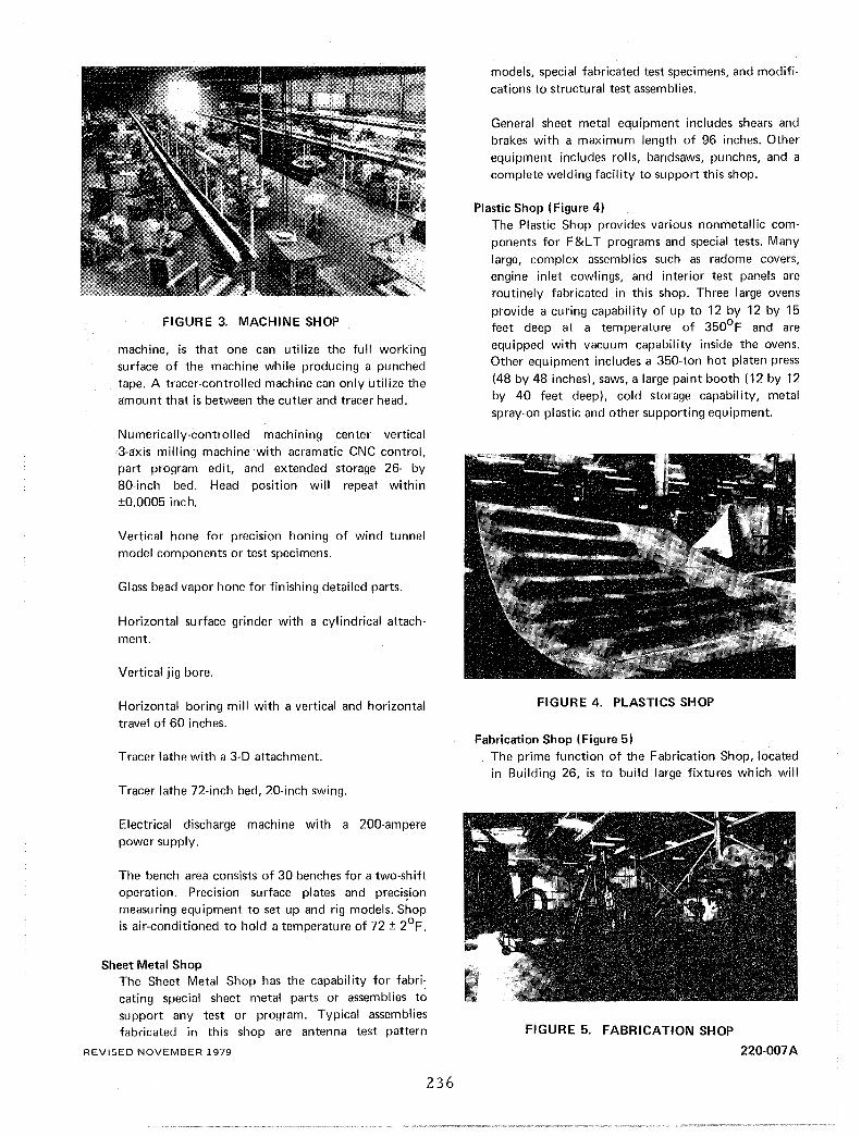
FIGURE 3. MACHINE SHOP
machine, is that one can utilize the full working surface of the machine while producing a punched tape. A tracer-controlled machine can only utilize the amount that is between the cutter and tracer head.
Numerically-controlled machining center vertical 3-axis milling machine with acramatic CNC control, part program edit, and extended storage 26- by 80-inch bed. Head position will repeat within ±0.0005 inch.
Vertical hone for precision honing of wind tunnel model components or test specimens.
Glass bead vapor hone for finishing detailed parts.
Horizontal surface grinder with a cylindrical attachment.
Vertical jig bore.
Horizontal boring mill with a vertical and horizontal travel of 60 inches.
Tracer lathe with a 3-D attachment.
Tracer lathe 72-inch bed, 20-inch swing.
Electrical discharge machine with a 200-ampere power supply.
The bench area consists of 30 benches for a two-shift operation. Precision surface plates and preci~ion
measuring equipment to set up and rig models. Shop is air-conditioned to hold a temperature of 72 ± 2°F.
Sheet Metal Shop The Sheet Metal Shop has the capability for fabri: cating special sheet metal parts or assemblies to support any test or program. Typical assemblies fabricated in this shop are antenna test pattern
REVISED NOVEMBER 1979
236
models, special fabricated test specimens, and modifications to structural test assemblies.
General sheet metal equipment includes shears and brakes with a maximum length of 96 inches. Other equipment includes rolls, bandsaws, punches, and a complete welding facil ity to support this shop.
Plastic Shop (Figure 4) The Plastic Shop provides various nonmetallic components for F&L T programs and special tests. Many large, complex assemblies such as radome covers, engine inlet cowlings, and interior test panels are routinely fabricated in this shop. Three large ovens
provide a curing capability of up to 12 by 12 by 15 feet deep at a temperature of 350°F and are equipped with vacuum capability inside the ovens. Other equipment includes a 350-ton hot platen press (48 by 48 inches), saws, a large paint booth (12 by 12 by 40 feet deep), cold storage capability, metal spray-on plastic and other supporting equipment.
FIGURE 4. PLASTICS SHOP
Fabrication Shop (Figure 5) The prime function of the Fabrication Shop, located in Building 26, is to build large fixtures which will
FIGURE 5. FABRICATION SHOP
220-007A

hold test specimens and to fabricate other miscellane
ous components_ Heavy-duty equipment, such as shear, brake, drill press, saws, and automatic feed welding machines, are available in this shop_
Electrical/Electronic Shop The Electrical/Electronic Shop, located in the Engi
neering Development Center, Building 41A (Figure 6), performs various degrees of maintenance on electrical/electronic systems, e_g., microwave systems, radios, telemetry, and airborne digital data
systems associated with flight test aircraft. I n addition, the shop is equipped and staffed to: (1) manage
the complete fabrication of flight test and support instrumentation, (2) fabricate instrumentation racks and consoles, (3) stamp identification numbers on
wires and sleeves, (4) wire wrap printed circuit
boards, and (5) assemble cables and wire runs.
The shop personnel also install strain gages and foil-type temperature pickups on test aircraft. However, to ensure proper installation and eliminate the possibilities of receiving irrelevant data, trial or mockup installations are made on test models, aircraft components, and airframe structures. This procedure is used to satisfy all types of environmental test prerequisites such as high and low temperatures, long-term stability, and temperature compensation.
REVISED NOVEMBER 1979 237
FIGURE 6, F< ELECTRICAL FABRICATION SHOP
Associated Electrical Equipment Includes:
Blue Line Oven, Model FC-812 Delta Design Environmental Chamber, Model 2850L Delta Design Environmental Chamber, Model MK3900 Conrad/Missemer Freezer Coded Communication, Model ECO-3 John Fluke Voltage Calibrator, Model 313 Hallcross Resistance Box
Two Kingsley Wire Stamp Machines, Model KWE-7-B American Pacific Trojan Wire Marker
Gardner Denver Company Wire Wrap Machine, Model 144A-1
SLI Photoelectric Reader, Model PER-300_
220-007B

/DOUGILAS A8RCRAFT COMPANY /
MCDONNELL DOUGL~ CORPORATION
ENGINEERING AND RESEARCH TECHNICAL FACILITY DESCRIPTION
ACOUSTIC TEST FACI LlTI ES
The Acoustic Test Facilities provide for the investigation of materials, assemblies and subsystems primarily related to acoustical duct linings, aircraft equipment noise, and resistance of aircraft structures to sonic fatigue, and specialized facilities for studying the generation and suppression of noise. A major test facility for acoustics, the
Anechoic Acoustic Test Facility at EI Segundo, is described in a separate section.
The absorptive characteristics of acoustically treated test panels in acoustic and aerodynamic environments (like those in jet engine inlet and exhaust ducts) are measured in the Duct Transmission Loss Facility shown in Figure 1. A rectangular test duct is mounted between two reverberant chambers. The length of the test panels (L) mounted in the
sidewalls of this duct and the duct width (H) can be selected to attain various L/H ratios. The direction of one
of the chambers can be either with or against a specified airflow (up to Mach 0.7) to simulate engine exhaust ducts or inlets. Sound pressure levels in each chamber are
analyzed to determine the transmission loss due to the
presence of the test panels.
FIGURE 1. DUCT TRANSMISSION LOSS FACILITY
The resistance of aircraft structures to fatigue induced by high-intensity acoustical environments is determined in the Sonic Fatigue Facility (Figure 2), A noise generator with an
exponential horn is attached to a rectangular Progressive Wave Tube (PWT) containing a test section and an absorptive termination section. As the acoustic waves travel the length of the tube, they graze the test panel which is mounted to one side of the PWT, exciting it at a specified
REVISED NOVEMBER 1979
238
FIGURE 2. SONIC FATIGUE FACILITY
noise spectrum and level. Discrete frequency, broadband random, and combinations of these excitations can be produced. Testing at sound pressure levels substantially
greater than those encountered in service can uncover structural deficiencies in a relatively short period of
time.
Resistance to normal flow (the fundamental parameter describing porous, acoustically absorptive lining materials
used to suppress noise in many aircraft installations) is measured at various velocities in the Flow Resistance Facility shown in Figure 3. The equipment consists of
FIGURE 3. FLOW RESISTANCE FACILITY
FACILITY LOCATION 1 DEPTN2~'7 CITY 1 STATE
Long Beach
IBLDG NO.
29/41 A
California
213-025-1

airflow controls, metering, and pressure-drop/temperature
instruments. Although small samples are usually tested, flow resistance can be measured for specification compli
ance checks of larger sheets to be used in fabricating
full-size parts.
The impedance and absorption of acoustical materials are
determined in the Standing Wave Apparatus (Figure 4)
which consists of a selection of tu.bes, loud-speakers with horn attachments, and a probe microphone which traverses
the length of the tube axis. The characteristics of the standing wave pattern (i,e" relative to sound pressure levels
and acoustic mode/anti node locations) produced from normally incident sounds at selected discrete frequency and sound pressure level are determined from probe micro
phone data.
These data are input to a digital computer to calculate the
real and reactive components of the complex acoustic impedance and the normal incidence absorption coefficient.
FIGURE 4. STANDING WAVE APPARATUS
For flyover noise recording and other tests at remote locations, the Acoustics and Vibration Van (Figure 5) has been equipped with multichannel recording capability, A self-contained electrical power system supplies a complete complement of test and support equipment including signal conditioning and monitoring systems. I n addition, there is a very high frequency (VHF) transceiver, a receiver for time code signals, radio telephone, long-line remote microphone systems, calibration equipment, and a graphic level re
corder. As currently configured, the van carries up to 11 long-line microphone stations which can be deployed to
distances of 10,000 feet or more. I n addition, for remote locations where the use of long cables is impractical,
self-contained remotely-controlled noise-recording systems
are available.
REVISED NOVEMBER 1979 239
FIGURE 5. ACOUSTICS AND VIBRATION VAN
Noise data processing is conducted using the facilities of the Acoustics and Vibration Data Center (Figure 6). The Data Center is equipped with a number of multiple-channel and
single-channel magnetic tape systems and a variety of data processing systems. Data systems include: (1) computer
controlled audio filter system with 1/3-octave-band parallel outputs onto digital tape for subsequent large-scale computer processing; (2) narrow-band spectrum analyzers with variable averaging; (3) computer-controlled processing system for paired-signal analysis in both time and frequency domains using Fourier Transform methods with graphical and tabular output capabilities; and (4) statistical processors with probability and correlation output modes. In addition, multichannel strip chart recorders and necessary peripheral equipment such as time code, signal conditioning and audio output subsystems are incorporated.
y
FIGURE 6. ACOUSTICS AND VIBRATION DATA CENTER
Systems developed by Douglas for acoustical data acquisition include those for specialized flyover noise testing to the standards of Part 36 of the U,S. Federal Aviation Regulations and Annex 16 of the International Civil Aviation Organization.
213-025-2
Operational Characteristics:
Duct Transmission Loss Facility
Maximum Specimen Size: Width - 8 inches Length - 48 inches Thickness - 4 inches
Duct Cross Section: Height - 10.375 inches Width variable from 2 to 17 inches L/H Ratio: 0 to 24 Mach Number: 0 to 0.7
Reverberation Chambers (inlet and exhaust): 4.2 by 5.2 by 6.5 feet high with 35· by 40-inch-high access door
Noise Source: Ling EPT-200 and Airjets (see Noise Generators)
Sonic Fatigue Facility
Maximum Specimen Size: 20.25 by 27.00 inches long (small window) 50.0 by 60.0 inches long (large window) 60.0 by 70.0 inches long (door)
Progressive Wave Tube, Cross Section: 12.45 by 62.25 inches high Noise Source: Noraircoustic MK VII and Ling EPT-200 (see Noise Generators)
Flow Resistance Facility
Maximum Specimen Size: 1.2 by 2.4 meters; 0.8 meter thick Velocity: 0.70 to 10.0 meters/second through a O.l-meterdiameter test area Flow Resistance: 50 to 10,000 mks Rayls
Standing Wave Apparatus
Maximum Specimen Size: 10 cm diameter for 90 to 1,800 Hz 3 cm diameter for 800 to 6,500 Hz 1.5 cm diameter for 5,000 to 10,000 Hz
Normally Incident Sound: 90. to 155-dB sound pressure level at 1/3-octave·band center frequencies of 400 to 10,000 Hz
Standing Wave Ratio: 45 dB
REVISED NOVEMBER 1979 240
Noise Generators:
Noraircoustic MK VII: Electrohydraulic 200,000 acoustic watts Random frequency range: 40 to 10,000 Hz Up to 172 dB in Sonic Fatigue Facility
Ling EPT·200: E lectropneu matic 10,000 acoustic watts Sinusoidal frequency range: 40 to 1,250 Hz Random frequency range: 40 to 10,000 Hz Up to 158 dB in Sonic Fatigue Facility
Maximum air supply: 7,100 scfm (9 pounds/second) Combined 250 and 300 psig systems Reference Pneumatic Test Facilities, Section 217·003
Applications:
The Acoustic Test Facilities are actively utilized in experimental research on sources and effects of sound as related to the products produced by Douglas.
The following are some of the more specific programs that are being investigated:
Fan duct noise propagation and absorption APU inlet/exhaust muffler Fan duct deSign Sidewall transmission loss Environmental control system and component noise Aircraft equipment noise control Psychoacoustics studies Jet noise suppression Propulsive lift system noise Panel absorption Fan noise source definition and suppression Panel acoustic loads and stress Near-Field noise measurements Airport noise surveys Factory noise surveys Community noise surveys Flyover noise surveys
Instrumentation:
A large assortment of condenser microphones of 1-, 1/2-, 1/4-, and 1I8-inch diameters, both pressure and free-field types, are maintainted, In addition, high-frequencyresponse pressure transducers with pressure rakes are
213-025A-3

available for airflow velocity and turbulence measurements for correlation with acoustical data.
Suitable types and quantities of microphone preamplifiers, field-effect-transist~r-type cathode followers, power supplies, and multichannel magnetic tape recorders with a
variety of recording electronics are availlable to meet the needs of several laboratory, field, and flight tests concurrently.
In addition, several portable single-channel sound-recording
systems of the system shown in Figure 7 are maintained as primary test recording systems and to supplement facility
systems.
241 REVISED NOVEMBER 1979
FIGURE 7. PORTABLE FLIGHT AND FIELD SOUND RECORDING SYSTEM
213-025-4
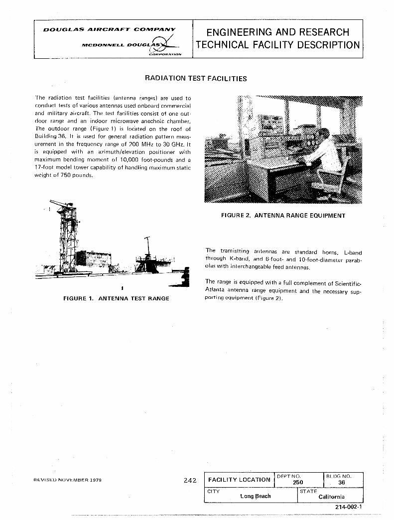
DOUGLAS AIRCRAFT COMPANY /
MCDONNELL DOUGL~ CORPORATION
ENGINEERING AND RESEARCH TECHNICAL FACILITY DESCRIPTION
RADIATION TEST FACILITIES
The radiation test facilities (antenna ranges) are used to conduct tests of various antennas used onboard commercial and military aircraft. The test facilities consist of one outdoor range and an indoor microwave anechoic chamber. The outdoor range (Figure 1) is located on the roof of Building 36. It is used for general radiation pattern measurement in the frequency range of 200 MHz to 30 GHz. It is equipped with an azimuth/elevation positioner with maximum bending moment of 10,000 foot-pounds and a 17-foot model tower capability of handling maximum static weight of 750 pounds.
FIGURE 1. ANTENNA TEST RANGE
REVISED NOVEMBER 1979 242
FIGURE 2. ANTENNA RANGE EQUIPMENT
The tramistting antennas are standard horns L-band through K-band, and 6-foot- and 10-foot-diame;er parabolas with interchangeable feed antennas.
The range is equipped with a full complement of Scientific
Atlanta antenna range equipment and the necessary supporting equipment (Figure 2).
IDEPT NO. I BLDG NO. FACILITY LOCATION 250 36
CITY I STATE Long !3each 1 Calitornia
214-002-1

[
DOUGLAS AIRCRAFT CONIPANY
/
ftIICDONNELL DOUGL~ CORPORATION
ENGINEERING AND RESEARCH TECHNICAL FACILITY DESCRIPTION
AUTOMATED GRAPHICS SYSTEM
The Automated Graphics System is a computing facility (Figure 1) for producing graphics from digital data, or converting graphics to digital data, using a Gerber Flatbed Plotter (an X-Y coordinate positioning device) or a Versatec
Electrostatic Plotter connected to a minicomputer con
troller. These systems operate from on-line telecommunications with an IBM 3033 system.
FIGURE 1_ AUTOMATIC GRAPHICS PLOTTING ROOM
The Gerber Data Management System (OMS) is an element
of a distributed processing system that provides data storage, communications, and processing services to system networks. Other elements in the network may be programcontrolled digitizing or drafting systems (such as the Gerber 2075 and 4477), remote large-scale computing systems, or additional OMS systems.
Graphics (Engineering drawings, patterns and geometric designs for stencils or artwork, data plots, etc.) up to 5 by 16 feet are created by designers using computer programs or cathode ray tubes. This information is then transmitted to the Gerber or Versatec for plotting, Figure 2 and 3.
Digital data (area and weight calculations, trace for drawing configurations, numerical/control (N/C) tape, flight path studies, or any application requiring numeric data from Graphics) are obtained by utilization of the automatic line follower to convert graphics to digital format.
The facility consists of three systems which provide support for Acoustics, Aerodynamics, Flight Test, Interiors,
REVISED NOVEMBER 1979
243
Mechanical, Power Plant, Structural Mechanics and Structures, while having the capability to provide support or interface with Tooling and Manufacturing.
FIGURE 2. VERSATEC PLOTTER
FIGURE 3_ SYSTEM IllUSTRATION
Operational Characteristics
Gerber Flatbed
Table Size (Usable area) 5 by 16 Feet (With Vertical Tilting Capability) 5 by 16 Feet (High-Speed Nontilting)
I
DEPT NO. IBLDG NO. FACILITY LOCATION 250 $
CITY ISTATF Long Beach California
220-003-1

Maximum Drafting Speed 500 Inches/Minute (2075 System) 2800 Inches/Minute (4477 System)
Maximum Digitizing Speed 180 Inches/Minute (2075 System)
Output Head Wet Pen, Ballpoint Pen, Fibertip Pen, Scribe, Stencil Cutter
Plotting Media Paper, Vellum, Mylar, Scribecoat, Rubylith, Stencil Material
Accuracy (Drafting) (±) 0.004 Inch (Overall)
Resolution (Drafting) (±) 0.0005 Inch
Repeatability (Drafting) (±) 0.002 Inch
Telecommunication Speed 4800/9600 Baud
Paper Tape Reader Speed 300 CPS
Paper Tape Punch Speed 120 CPS
Versatec Electrostatic
Plot Size (Usable Area) 35.19* *Limited only by size of paper roll (500 feet)
Plotting Speed 1584 Square Inches/Minute
Plotting Media Bond or translucent paper
Accuracy (±) 0.2 percent of 0.015 maximum accumulated error (adjustable in X axis by software)
Resolution (±) 0.005
Applications
The Automated Graphics System provides graphics or digital data output for the following:
Engineering layouts and production drawings are created or
REVISED NOVEMBER 1979
244
modified using computer-aided design drafting (CADD), Data Coded Geometrical Operation (DACGO) program subroutines, automatic programmed tool (APT), Fortran or Gerber language and transmitted via telecommunication lines to the plotting systems.
Area and weight calculations, flight path studies, or any application where numeric data are required from Graphics and are obtained by operating the Gerber plotters in the digitizing mode. Also, by utilizing a cutter offset routine, the digitizing program will provide, in N/C machine tool format, data for use in preparation of N/C tapes.
Producing paint stencils for exterior aircraft markings is accomplished by programming in Gerber or taking marking artwork (customer-furnished or Douglas-designed) and photographing to desired scale, utilizing opti-copy camera. The shape defined on photoprint is digitized for digital data moved to a CADD access data storage area where additional shape definition is added and a hardcopy file is produced
which can be plotted on stencil stock.
Aerodynamic and Power Plant performance graphs and Acoustic contour curves are derived from theoretical, wind tunnel test models, flight test aircraft, etc., and processed by programs for data to be transmitted via telecommunication lines to the Gerber or Versatec for plotting.
N/C tape verifications.
Stress analysis diagrams.
Mechanism motion study drawings.
Geodetic survey (tract, topographical, etc.).
Geometric patterns for interior ceiling and side panels.
N/C tapes for automatic drilling and wire wrapping machine.
Associated Equipment
Gerber Optical line following with line lock-on capability to allow operator to digitize "hands off" mode.
Camera and TV monitor to allow the operator a "follower's eye view" of the graphics being digitized.
ASR-33 teletype unit for machine control and I/O opera
tion.
Adds 520 console for machine control I/O operation and
data manipulation.
High-speed paper tape punch for output of EIA (Electronic Industries Association) or ASCII (American Standard Code
220-003-2

for Information Interchange) data on punched paper tape.
Tektronix 4014 CRT storage tube for previewing data prior to plot.
Tektronix 4631 hard copy unit.
4954 graphics tablet for fast-digitizing or free-hand graphics (34 by 42 inches).
DTC 382 time-sharing terminal for data management.
i REVISED NOVEMBER 1979 245
Minicomputer Controllers
Honeywell DDP-516 Eight K Memory Hewlett-Packard 2108 Sixteen K Memory Hewlett-Packard 2112 Eighty K Memory Interdata 180-4 Sixty-Four K Memory
Disk Drives Hewlett-Packard 7900A Five Megabytes CDC 9762 Eighty Megabytes
220-003A

,. Report No. 2. Government Accession No. NASA CR 167895
4. Title and Subtitle
Advanced Turboprop Testbed Systems Study
7. Author(s)
1. M. Goldsmith
3. Recipient', Catalog No.
6. Report Date
7/82 L
6. Performing Organization Code
8. Performing Organization Report No. ACEE-22-FR-1669A, 10/81
..... ------------------------------1 10. Work Unit No. 9. Performing Organization Name and Address
Douglas Aircraft Company 3855 Lakewood Blvd. Long Beach, California 90846
12. SoonsQfing AlIen\:y Name and Address d Nat10naI aeronaut1cs an Space Administration Lewis Research Center 21000 Brookpark Road C!1 pvpl ;mel Ohi n 4411'i
16. ~g~tn;n~~lNWJnitor: Brent A. Miller, MS 301-2 NASA Lewis Research Center 2100 Brookpark Road Cleveland, Ohio 44135
11. Contract or Grant No.
NAS3-22:347
14. Sponsoring Agency Code
16. Abstract The work performed by Douglas Aircraft Company, with Hamilton Standard and Detroit Diesel·Allison as subcontractors, provides a recommended NASA program for establishing the proof. of concept, feasibility, and verification of the advanced prop-fan and of the integrated advanced prop-fan aircraft. The use of existing hardware is compatible with having a successfully expedited testbed ready for flight in 1986. The study considers the DC-9-10 (or -30) as the testbed aircraft; Hamilton Standard SR-3 design type prop-fan; the Allison T701, the Allison T56, and the General Electric T64 turboshaft engine; one and two prop-fan nacelles with the two nacelle prop-fan as the primary arrangement. An approximate 10 foot diameter propfan is considered necessary for the flight test to provide adequate scaling which may arise in the application of test results to full scale aircraft.
The facets of the overall testbed program 'included in this study are the program objectives and priorities; survey and selection of candidate propeller drive systems; selection of a satisfactory aircraft; proposed testbed systems evaluation and recommendations; conceptual design of testbed; ROM costs; preliminary testbed flight program; and survey of suitable wind tunnel facilities.
Major conclusions are: A prop-fan testbed aircraft is definitely feasible and necessary for verification of prop-fan/prop-fan aircraft integrity. The DC-9 aircraft is a particularly desirable testbed aircraft. The Allison T70l is most suitable as a propulsor and modification of existing engine and propeller controls are adequate for the testbed. The airframer is considered the logical overall systems integrator of the testbed program. Large scale wind tunnel testing is not adequate for validation of the prop-fan aircraft. •
17. Key Words (Suggested by Author(s))
DC-9-l0 Prop-fan Testbed Prop-fan Testbed - Prop-fan Flight Research - Prop-fan
18. Distribution Statement
Unrestricted
Wind Tunnel Facilities - Prop-fan Acoustics - Prop-fan 19. Security Classif. (of this report)
Unclassified 20. Security Classif. (of this pagel
Unclassified 21. No. of Pagss
252
.. For sale by the National Technical Information Service, Springfield, Virginia 22151 .
22. Price"

End of Document