Advanced Stirling Convertor Testing at GRC · 2013-08-22 · Advanced Stirling Convertor Testing at...
12
www.nasa.gov Advanced Stirling Convertor Testing at GRC Presented by: Nick Schifer Sal Oriti Thermal Energy Conversion Branch NASA Glenn Research Center May 1, 2013 https://ntrs.nasa.gov/search.jsp?R=20130014472 2020-04-09T01:57:45+00:00Z
Transcript of Advanced Stirling Convertor Testing at GRC · 2013-08-22 · Advanced Stirling Convertor Testing at...

www.nasa.gov
Advanced Stirling Convertor Testing at GRC
Presented by:
Nick Schifer
Sal Oriti
Thermal Energy Conversion Branch
NASA Glenn Research Center
May 1, 2013
https://ntrs.nasa.gov/search.jsp?R=20130014472 2020-04-09T01:57:45+00:00Z

National Aeronautics and Space Administration 2
Background
Advanced Stirling Radioisotope Generator
• Next generation radioisotope-fueled power system
• Lockheed Martin Space Systems is System Integration Contractor
• Suitable for deep-space or other missions without solar power
• Two dual-opposed free-piston Stirling convertors
• > 20% thermal-to-electric conversion at system level
• 1st use of dynamic energy conversion in space
• Necessitates demonstration of conversion technology long-term performance
ASRG System Schematic

National Aeronautics and Space Administration 3
Background
Advanced Stirling Convertor
• Designed and Manufactured by Sunpower, Inc.
• Development initiated in 2004 via NASA technology development contract
• 6 stages of development:
1. ASC-0
2. ASC-1
3. ASC-1HS
4. ASC-E - First Engineering Unit design
5. ASC-E2 - Engineering Unit design with high-temp heater head
6. ASC-E3 - Pathfinder for Flight Unit production
ASC-E3 as-built hardware
Technology Development

National Aeronautics and Space Administration 4
Test Methodology
Three types of tests are performed:
1. Performance Mapping
• Simulate range of expected operating temperatures
• Max/Min thermal input, max/min sink temperature
2. Durability Tests
• Demonstrate and quantify margin of ASC design
• Start/stop cycling, static acceleration, launch vibration, overstroke
3. Extended Operation
• Goal : 10s of thousands of hours
• 24/7, unattended operation
Implementation
• Electric heat source for heat input
• Laboratory circulator for heat rejection
• Automated data system
• Automated shutdown routines
• Thermocouples, thermistors for temperature
• Power meters for voltage, current, power
• LabView data acquisition software
ASC Operation Schematic
Electric Heat
Source
Cold End
Hot End
Alternator
Fluid Flow
Electrical Output
Thermal Input
National Aeronautics and Space Administration
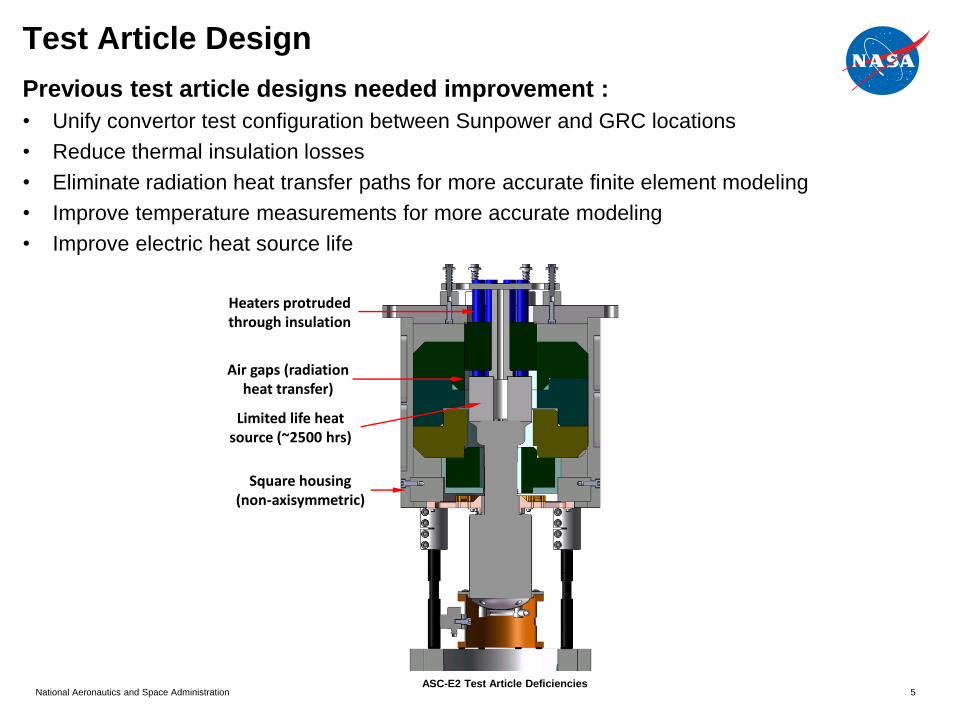
Test Article Design
Previous test article designs needed improvement :
• Unify convertor test configuration between Sunpower and GRC locations
• Reduce thermal insulation losses
• Eliminate radiation heat transfer paths for more accurate finite element modeling
• Improve temperature measurements for more accurate modeling
• Improve electric heat source life
Heaters protruded through insulation
ASC-E2 Test Article Deficiencies
Air gaps (radiation heat transfer)
Square housing (non-axisymmetric)
Limited life heat source (~2500 hrs)
5
National Aeronautics and Space Administration
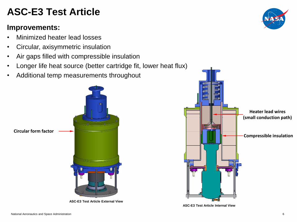
ASC-E3 Test Article
Heater lead wires (small conduction path)
ASC-E3 Test Article External View
ASC-E3 Test Article Internal View
Compressible insulation Circular form factor
6
Improvements:
• Minimized heater lead losses
• Circular, axisymmetric insulation
• Air gaps filled with compressible insulation
• Longer life heat source (better cartridge fit, lower heat flux)
• Additional temp measurements throughout
National Aeronautics and Space Administration 7
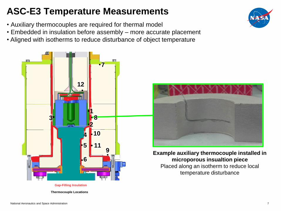
Gap-Filling Insulation
Thermocouple Locations
1
2 3
4
5
6
7
9
• Auxiliary thermocouples are required for thermal model
• Embedded in insulation before assembly – more accurate placement
• Aligned with isotherms to reduce disturbance of object temperature
Example auxiliary thermocouple installed in
microporous insualtion piece
Placed along an isotherm to reduce local
temperature disturbance
8
10
11
12
ASC-E3 Temperature Measurements

8
7 kHz
7 kHz
Alternator
Power Meter
Heat Distributor
Heater Power
Meter
V+
V-
I
AC Bus
Power Meter V+
V-
I Piston
Position
Sensor
Processor
PID Temp Controller
DC Power Supply
Pearson Coils
Net Heat Input
(calc)
AC Power Supply
(variable freq.)
High-rate voltage
and current
waveform archival
Capacitor
Load
High-rate piston
position
waveform
archival
V-
V+
Alternator Housing Temp
Surface TCs
Thermistors
Cold End Temp
TC probes
Thermistors
Hot End Temp
TC probes
Heat Source Temp
TC probes
ASC-E3 Performance Measurement Instrumentation

National Aeronautics and Space Administration
ASC-E3 Test Station
ASC-E3 Test Station
Circulators Cold-end temp control
9
• Simultaneous operation of a pair of convertors
• Vertical orientation
• Independent operating condition control
2 Convertors Side-by-side
Vertical orientation
Test Rack Data acquisition
Monitoring Operating point control

National Aeronautics and Space Administration
ASC-E3 Data Archival and Processing
10
• Centralized storage of data from all test stations
• All parameters measured and recorded every 2 seconds
• 5-minute-window average point stored each hour
• Dynamic data sampled and stored at 7 kHz
• Operator notes stored in an event log
Test Rack
Data Server
6TB array
RAID5
2-sec data
5-min avgs
Event log
20 TB array
RAID5
Daily Transfer
Ethernet
7 kHz data
50 GB/hr
Matlab plotting script
• Automated 24-hr plot generation
• User-customizable plotting options
• Automatic population of operator notes on time axis
• Automatic plot naming and storage
• Engineers can examine plots to analyze
performance
Daily
60
65
70
75
80
85
90
95
100
#2
Alt
FT
Pw
r(W
e)
0 5 10 15 20 2560.0
65.0
70.0
75.0
80.0
85.0
90.0
95.0
100.0
Hours
#1
Alt
FT
Pw
r(W
e)
ASC-E3 #1 & #2Sat 2013-Mar-09 00:00:00Sat 2013-Mar-09 23:59:58
#1 Alt FT Pwr(We)
#2 Alt FT Pwr(We)
National Aeronautics and Space Administration
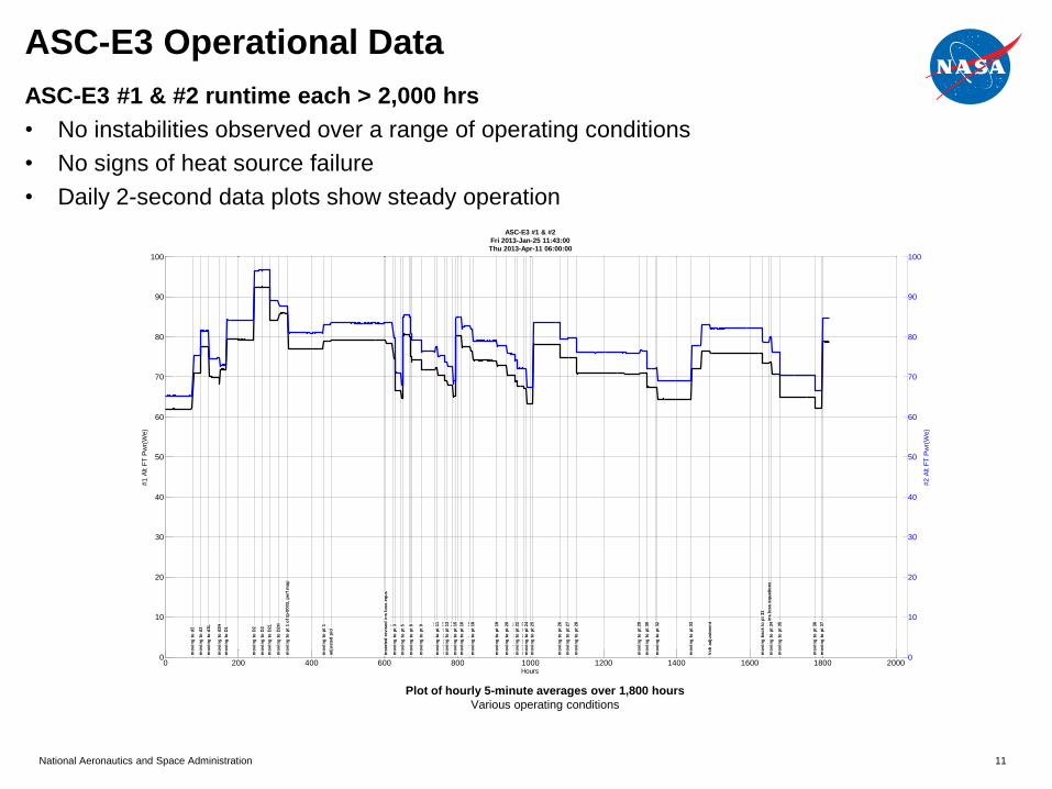
ASC-E3 Operational Data
11
ASC-E3 #1 & #2 runtime each > 2,000 hrs
• No instabilities observed over a range of operating conditions
• No signs of heat source failure
• Daily 2-second data plots show steady operation
0
10
20
30
40
50
60
70
80
90
100
#2 A
lt F
T P
wr(
We)
0 200 400 600 800 1000 1200 1400 1600 1800 20000
10
20
30
40
50
60
70
80
90
100
Hours
#1 A
lt F
T P
wr(
We)
ASC-E3 #1 & #2
Fri 2013-Jan-25 11:43:00
Thu 2013-Apr-11 06:00:00
mo
vin
g t
o d
2
mo
vin
g t
o d
3
mo
vin
g t
o d
3L
mo
vin
g t
o d
2H
mo
vin
g t
o D
1
mo
vin
g t
o D
2
mo
vin
g t
o D
3
mo
vin
g t
o D
2L
mo
vin
g t
o D
2H
mo
vin
g t
o p
t 1 o
f tp
-0003,
perf
map
mo
vin
g t
o p
t 1
ad
juste
d p
id
insert
ed
revis
ed
in
s l
oss e
qu
s
mo
vin
g t
o p
t 2
mo
vin
g t
o p
t 3
mo
vin
g t
o p
t 4
mo
vin
g t
o p
t 5
mo
vin
g t
o p
t 6
mo
vin
g t
o p
t 7
mo
vin
g t
o p
t 8
mo
vin
g t
o p
t 9
mo
vin
g t
o p
t 10
mo
vin
g t
o p
t 11
mo
vin
g t
o p
t 12
mo
vin
g t
o p
t 13
mo
vin
g t
o p
t 14
mo
vin
g t
o p
t 15
mo
vin
g t
o p
t 16
mo
vin
g t
o p
t 17
mo
vin
g t
o p
t 18
mo
vin
g t
o p
t 19
mo
vin
g t
o p
t 20
mo
vin
g t
o p
t 21
mo
vin
g t
o p
t 22
mo
vin
g t
o p
t 23
mo
vin
g t
o p
t 24
mo
vin
g t
o p
t 25
mo
vin
g t
o p
t 26
mo
vin
g t
o p
t 27
mo
vin
g t
o p
t 28
mo
vin
g t
o p
t 29
mo
vin
g t
o p
t 30
mo
vin
g t
o p
t 31
mo
vin
g t
o p
t 32
mo
vin
g t
o p
t 33
Vch
ad
justm
en
t
mo
vin
g b
ack t
o p
t 33
revert
ing
to
old
in
s l
oss e
qu
ati
on
sm
ovin
g t
o p
t 34
mo
vin
g t
o p
t 35
mo
vin
g t
o p
t 36
mo
vin
g t
o p
t 37
Plot of hourly 5-minute averages over 1,800 hours
Various operating conditions

National Aeronautics and Space Administration
ASC Operation Summary
12
ASC Model # Units Total Runtime Status
ASC-0 4 92,000 Ongoing
ASC-1 2 3,700 Ongoing
ASC-1HS 2 11,000 Complete
ASC-E 4 100,000 Ongoing
ASC-E2 8 54,000 Ongoing
ASC-E3 2 4,000 Ongoing
Total = 263,900