ADVANCED SOLAR CAR - Scorpio Technology · Note 2: Alternatively, the programs “Crocodile...
12
1 ADVANCED SOLAR CAR CONTENTS: Section 1: General and Planning Information Section 2: Components and Material Required Section 3: Assembling the PCB & Components Section 4: Making the Vehicle Section 5: Wiring Section 6: Testing and Set-up Section 7: How the Circuit Works (Theory) DESCRIPTION The ADVANCED SOLAR CAR is a four- wheeled basic vehicle, driven by an electric motor and powered by a purpose designed solar panel. This vehicle also has a SOLAR PANEL POWER CONTROLLER – LOW VOLTAGE (SPPC- LV), which helps your vehicle to achieve maximum performance, by the use of an electronic circuit (device). Motion from the motor to the wheels is transferred by the use of gears. SECTION 1: GENERAL AND PLANNING INFORMATION 1. DESIGN CONSIDERATIONS 1.1 DESCRIPTION – SOLAR PANEL The Solar panel is a purpose-designed unit, consisting of 4 sections, and these can be connected in series or parallel. The use of 4 sections is ideal for experimentation, as it means that not all 4 have to be connected at the same time – you can connect the sections to provide the amount of voltage and current as required. For example, you could connect only one section, to see how the vehicle will perform. Then connect just 2 sections in series, then 3, and finally all 4. You can then carry out similar tests in parallel. Thus, the vehicle made from this kit has a lot of scope for various trials and experiments. 1.2 DESCRIPTION – SOLAR PANEL POWER CONTROLLER This kit includes a SOLAR PANEL POWER CONTROLLER - LOW VOLTAGE. The SOLAR PANEL POWER CONTROLLER is useful, as powering an electric motor directly from a solar panel can be inefficient. The SOLAR PANEL POWER CONTROLLER circuit holds the output of the solar panel at a preset voltage, and is able to substantially increase the starting current to the motor. NOTE: The SOLAR PANEL POWER CONTROLLER – LOW VOLTAGE will only work, with ALL the sections of the solar panel connected in SERIES (providing 6.0 volts). SCORPIO TECHNOLOGY VICTORIA PTY. LTD. A.B.N. 34 056 661 422 17 Inverell Ave., Mt. Waverley, Vic. 3149 Tel: (03) 9802 9913 Fax: (03) 9887 8158 Revised: 25 August 2015 www.scorpiotechnology.com.au [email protected] Issued: 17 February 2013 www.scorpiotechnology.com.au
-
Upload
truongtram -
Category
Documents
-
view
228 -
download
0
Transcript of ADVANCED SOLAR CAR - Scorpio Technology · Note 2: Alternatively, the programs “Crocodile...

1
ADVANCED SOLAR CAR CONTENTS: Section 1: General and Planning Information Section 2: Components and Material Required Section 3: Assembling the PCB & Components Section 4: Making the Vehicle
Section 5: Wiring Section 6: Testing and Set-up Section 7: How the Circuit Works (Theory)
DESCRIPTION The ADVANCED SOLAR CAR is a four-
wheeled basic vehicle, driven by an
electric motor and powered by a purpose designed solar panel.
This vehicle also has a SOLAR PANEL
POWER CONTROLLER – LOW VOLTAGE (SPPC-
LV), which helps your vehicle to achieve
maximum performance, by the use of
an electronic circuit (device).
Motion from the motor to the wheels is
transferred by the use of gears.
SECTION 1: GENERAL AND PLANNING INFORMATION
1. DESIGN CONSIDERATIONS
1.1 DESCRIPTION – SOLAR PANEL
The Solar panel is a purpose-designed unit, consisting of 4 sections, and these can be connected in series or parallel. The use of 4 sections is ideal for experimentation, as it means that not all 4 have to be connected at the same time – you can connect the
sections to provide the amount of voltage and current as required. For example, you could connect only one section, to see how the vehicle will perform. Then connect just
2 sections in series, then 3, and finally all 4. You can then carry out similar tests in parallel.
Thus, the vehicle made from this kit has a lot of scope for various trials and
experiments.
1.2 DESCRIPTION – SOLAR PANEL POWER CONTROLLER
This kit includes a SOLAR PANEL POWER CONTROLLER - LOW VOLTAGE. The SOLAR PANEL
POWER CONTROLLER is useful, as powering an electric motor directly from a solar panel
can be inefficient. The SOLAR PANEL POWER CONTROLLER circuit holds the output of the
solar panel at a preset voltage, and is able to substantially increase the starting current to the motor.
NOTE: The SOLAR PANEL POWER CONTROLLER – LOW VOLTAGE will only work, with ALL the
sections of the solar panel connected in SERIES (providing 6.0 volts).
SCORPIO TECHNOLOGY VICTORIA PTY. LTD. A.B.N. 34 056 661 422
17 Inverell Ave., Mt. Waverley, Vic. 3149 Tel: (03) 9802 9913 Fax: (03) 9887 8158
Revised: 25 August 2015 www.scorpiotechnology.com.au [email protected]
Issued: 17 February 2013 www.scorpiotechnology.com.au [email protected]

2
1.3 GENERAL DESIGN CONSIDERATIONS
The drawings provided are a starting point for the student – they show the prototype vehicle we made.
Before starting construction, the student needs to carefully plan and layout all of
the components. The plan view of our prototype vehicle is shown in the drawing below (Figure 2). However, the concept has scope for variation. Students should
design a vehicle to suit their own end usage. The exploded view of the car shows the relationship between the various
components. The design of the ADVANCED SOLAR CAR should be considered as a
complete unit, not just as separate parts.
Plan View – Showing Series Wiring
When deciding on the platform’s size:
The axle shaft and guide tube length provides an upper limiting factor (for the
width). Note: Cut-outs may be made in the platform, for the wheels, to allow a wider
vehicle to be constructed. The platform can be made from any piece of material, even a very narrow one, in
which case stability needs to be considered.
The student needs to determine the material from which the ADVANCED SOLAR CAR is
to be constructed. Our choice was PVC. Other materials may be used, such as acrylic and plywood.
Other things to consider:
Use the guide tubes as bearings for the axle shafts. This vehicle as shown is basic, but it also allows scope for the student to develop
and make a more sophisticated vehicle. Remember – keep the end use in sight. The vehicle can only travel in a fixed direction - either straight ahead or in a
predetermined circle. This (circular travel) can be achieved by mounting the front axle shaft on an angle.
Two spur and 3 pinion gears are supplied. This provides the designer with scope,
to select the desired acceleration and top speed of the vehicle. A number of combinations are possible with the supplied gears, and provides the designer a
choice of different vehicle speeds. Consider the effect of different gear ratios have on either acceleration or top speed. The student should calculate the ratios available.
Determine which spur gear / pinion gear combination to use. How do these various ratios translate into actual speed? Take into account wheel
size and motor speed (how fast does it spin under full sunlight? On an overcast day?).
Note 1: the maximum motor speed, at maximum efficiency, is approximately 4,500 rpm.
3
Note 2: Alternatively, the programs “Crocodile Clips” or “Yenka” are useful for simulating the operation of gears, and investigating their operation.
1.4 ITEMS FOR INVESTIGATION
This project provides a number of different aspects of the ADVANCED SOLAR CAR for
investigation. Some ideas are listed below.
The Solar panel is a purpose-designed unit, consisting of 4 sections, and these may be connected in series or parallel. The use of 4 sections is useful for
experimentation, as it means that you could experiment with the output of the panel in different configurations: Only one section to see how much power is output, what speed is attained
Using between 2 and 4 sections connected in Series Using between 2 and 4 sections connected in Parallel.
Establish conditions for using the solar panel’s 4 sections in series or parallel. Set up a test schedule for these experiments. NOTE: This testing should be carried out
without the SOLAR PANEL POWER CONTROLLER, as the SOLAR PANEL POWER CONTROLLER –
LOW VOLTAGE will only work, with ALL 4 sections connected in SERIES
If working in a class, you may wish to assemble a number of these vehicles with
different gearing. This will allow you to test the theory / calculations made for the various gearing combinations. This can be tested using a stopwatch over a known length of track (or a variety of distances – to establish when top speed is reached,
and what it is) How are these speeds affected by having the sections connected in series? In
parallel? Evaluate the suitability of various materials, such as PVC, acrylic and plywood or
balsa wood
Investigate adding steering. This could be either manual (set the steering in a chosen direction before each use) or controlled (how would you control it? Remote
control? You cannot use RC or IR controls with the solar panel as it doesn’t supply enough current for 2 motors. Or by a wired controller?). For some ideas on
steering, you could look at our FORKLIFT, RADIO CONTROLLED VEHICLE and FOLLOW
WHITE LINE VEHICLE.
You may wish to incorporate forward / reverse operation.
SECTION 2: COMPONENTS & MATERIAL REQUIRED
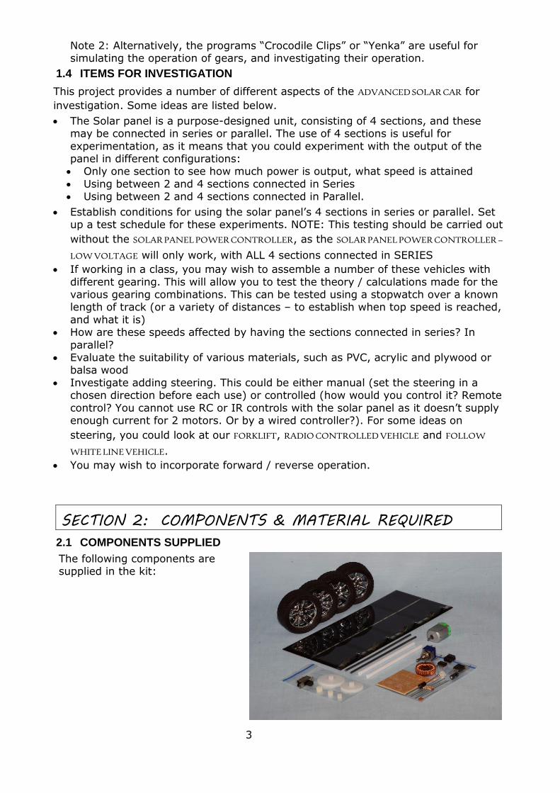
2.1 COMPONENTS SUPPLIED
The following components are supplied in the kit:

4
2.2 ADDITIONAL REQUIREMENTS
The following material is to be supplied by the student / designer:
Electric hook-up wire – Multi-strand Material for the platform (PVC or acrylic sheet, plywood, etc.) Copper wire - 1mm tinned
Hot glue or double-sided foam tape
2.3 TOOLS REQUIRED
The following tools are required:
Assorted hand tools Soldering equipment and solder Multimeter (MULTIM)
Resistor – 1.0 to 2.7 Ohm 10 watt (for testing)
SECTION 3: ASSEMBLING THE PCB & COMPONENTS
3.1 COMPONENTS FOR MOUNTING ON THE PCB
All the components supplied have to be assembled onto the PCB, with the exception of the Inductor.
3.2 MOUNTING COMPONENTS ONTO THE PCB
NOTE: The assembly of all the components should be carried out before soldering the
components in place. Begin with the components that sit lowest on the PCB.
Mount the resistors in place. Resistors
are non-polarised components and do
not need to be placed in any particular direction.
However, the convention is that
horizontal resistors are mounted with the gold band to the
right and for vertical resistors to the
bottom. Make sure when
mounting the zener
diode Z1 and semiconductor D1
that the negative end (the one with
SOLAR PANEL POWER CONTROLLER
the band) is mounted in the same direction as shown on the PCB. Both of these
components must be connected the correct way for the PCB to function.
The IC socket is mounted next: make sure that the notch on the socket faces in
the same direction as indicated on the PCB. Mount the trimpot in place. Mount the Electrolytic capacitor next. This capacitor is polarised: that is, it has
positive and negative leads. It must be connected the correct way for the PCB to
5
function. The positive and negative leads can be identified by two methods: (1) the stripe on the body of the capacitor marks the negative lead (2) the long lead is positive. Refer to the PCB to determine the position of the leads.
Mount the disc ceramic capacitor – this is not polarised and can be mounted in either direction, but it is preferable to mount it with the printed value visible (i.e.
facing you). The power Mosfet is mounted next. It must be mounted facing in the correct direction or it will be damaged when the PCB is connected to the Solar Cell.
Using a pair of insulated pointy nosed pliers, bend the centre lead out, about 3mm
from the two outside leads. Position the leads in their holes so that the metal back is facing towards the picture of the Mosfet on the PCB. Press on the plastic section
of the Mosfet and carefully bend it down on to the PCB.
3.3 SOLDERING THE COMPONENTS IN PLACE
NOTE: Check that all the components are in their correct positions: it pays to spend some time doing this before soldering the components. It can prevent wasted time later, trying to find out why the circuit doesn’t work and unsoldering and replacing
damaged or wrongly positioned components.
3.3.1. GENERAL PRINCIPLES
Turn over the P.C.B. and slightly bend the leads of the components outwards, to
prevent them slipping out Apply the soldering iron’s tip to the lead and track pad at the same time. Heat the
joint for 2-3 seconds and then apply the solder to the heated lead and pad on the
opposite side to the soldering iron tip. Melt the solder onto the hot pad and lead, not onto the soldering iron.
Once all the components have been soldered, use a pair of side cutters to cut off the ends of the leads – as close as possible to the solder
3.3.2. FURTHER ASSEMBLY
After all the soldering has been completed, insert the I.C. in its place in the socket.
Ensure the notch on the end faces in the same direction as on the socket. Check that the legs line up with the I.C. sockets holes and press down firmly with your
thumb. Note: it may be necessary to push the legs of the I.C. together slightly to line them up with the socket holes.
3.3.3. THE BYPASS SWITCH CIRCUIT
To install the Bypass (Toggle) Switch you will need to:
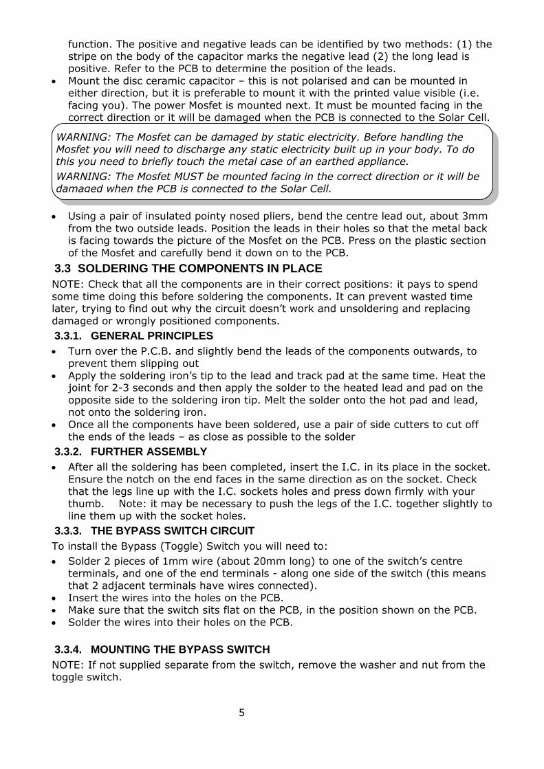
Solder 2 pieces of 1mm wire (about 20mm long) to one of the switch’s centre terminals, and one of the end terminals - along one side of the switch (this means
that 2 adjacent terminals have wires connected). Insert the wires into the holes on the PCB. Make sure that the switch sits flat on the PCB, in the position shown on the PCB.
Solder the wires into their holes on the PCB.
3.3.4. MOUNTING THE BYPASS SWITCH
NOTE: If not supplied separate from the switch, remove the washer and nut from the toggle switch.
WARNING: The Mosfet can be damaged by static electricity. Before handling the Mosfet you will need to discharge any static electricity built up in your body. To do this you need to briefly touch the metal case of an earthed appliance.
WARNING: The Mosfet MUST be mounted facing in the correct direction or it will be damaged when the PCB is connected to the Solar Cell.
6
Use another piece of tinned 1mm wire (about 30mm long) and bend it into a U shape around a 7mm drill.
Place the wire over the neck of the switch and insert it into the two
holes on the edge of the PCB, directly under the neck of the switch.
Pull the wire down so it sits snugly
around the neck of the switch. Solder the ends of the wire into
position.
Place the large flat washer on the switch. Screw the nut up against the washer and tighten it in place.
Note: this is to hold the switch firmly in place and prevent undue stress on the switch wires when the switch is operated.
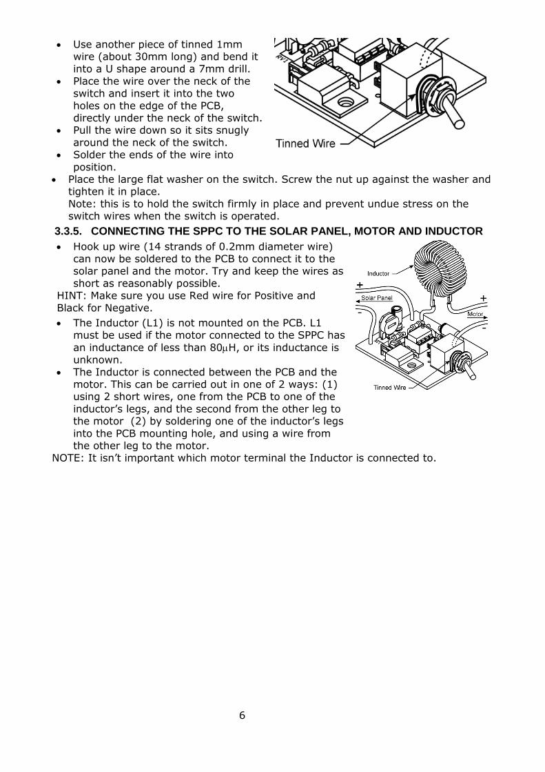
3.3.5. CONNECTING THE SPPC TO THE SOLAR PANEL, MOTOR AND INDUCTOR
Hook up wire (14 strands of 0.2mm diameter wire) can now be soldered to the PCB to connect it to the solar panel and the motor. Try and keep the wires as
short as reasonably possible. HINT: Make sure you use Red wire for Positive and
Black for Negative.
The Inductor (L1) is not mounted on the PCB. L1 must be used if the motor connected to the SPPC has
an inductance of less than 80H, or its inductance is unknown.
The Inductor is connected between the PCB and the motor. This can be carried out in one of 2 ways: (1) using 2 short wires, one from the PCB to one of the
inductor’s legs, and the second from the other leg to the motor (2) by soldering one of the inductor’s legs
into the PCB mounting hole, and using a wire from the other leg to the motor.
NOTE: It isn’t important which motor terminal the Inductor is connected to.

7
SECTION 4: MAKING THE VEHICLE
4.1 FABRICATION AND INITIAL ASSEMBLY
Cut the platform material to the required size.
Cut the steel shafts to the required length and de- burr the ends.
Press the selected spur gear (50
tooth or 60 tooth) onto the rear shaft, with enough of the shaft
protruding, through the gear, for the wheel to be pushed on.
HINT: Use a piece of wire to measure
the depth of the hole in the wheel
Insert the shafts into the guide
tubes. Press the wheels onto both shafts.
Install the pinion gear onto the motor’s shaft. It should finish flush with the end of the motor shaft.
NOTE: Do not push the gear too far, or it will rub on the motor casing.
4.2 MECHANICAL ASSEMBLY
Attach the solar panel to the platform, in the position chosen, using double-sided
foam tape. Attach the pre-assembled front axle (guide tube, shaft and wheels) to the platform
with hot glue or double sided tape.
NOTE: Ensure that the shaft guide tube is at right angles to the car’s platform and both guide tubes are parallel to each other, so that the car travels straight ahead–
unless you have chosen for the vehicle to travel in a circular path. Attach the pre-assembled rear axle (guide tube, shaft and the wheels and gear
assembly) to the platform with hot glue. Use hot glue or double-sided foam tape to attach the motor to the platform. The
pinion gear should engage the spur gear’s larger diameter gear, and the motor and
wheels should turn freely. Attach the switch to the chassis using hot glue or double-sided foam tape.
4.3 WIRING
You may wish to carry out a range of experiments, using the various combinations of the solar sections (series, parallel or a combination). If so, you would need to
retain the ability to change the connections as and when required. If this is the case, we recommend that the connections are made using alligator clips and wires, rather than soldering leads in place.
HINT: Place the pinion gear on the bench. Place he end of the motor shaft in the pinion gear hole. Use a hammer to tap the motor shaft at the end where it exits
the motor until the motor shaft hits the benchtop
WARNING: Don’t just push the motor down by hand as this can push the motor armature out of its bearings and jam the motor.
WARNING: If using hot glue, be very careful, as it can burn you if you get it on
yourself.

8
If you have decided on a specific solar section configuration (in accordance with the circuit schematics shown in Section 2), solder wires between the sections of the solar array, switch and motor.
NOTE: When soldering wires, strip a short piece of insulation from the end of the wire, twist the strands and use a hot soldering iron (approx. 350°C) to apply
solder. Test the operation of your solar car.
If the car goes in reverse, swap the wires connected to the motor, and solder
them in place. If the car goes forward as expected, solder the motor’s wires in place.
SECTION 5: WIRING
5.1 GENERAL
You may wish to carry out a range of experiments, using the various combinations of
the solar panel (one section, series or parallel). If so, you might like to be able to change the connections as and when required. If this is the case, we recommend that the connections between the solar panel’s sections be made using alligator clips and
wires, rather than soldering leads in place. Alternatively, a switch may be connected to simplify the changeover between series and parallel.
5.1.1. WIRING IN PARALLEL
The wiring diagram for parallel connection is shown at right.
Typical output in full sun is 3.0 Volts at 0.6 Amps.
REMINDER: The SPPC only works with all the solar sections wired in series.
WARNING: Take care when soldering to prevent burns.

9
5.1.2 WIRING IN SERIES
The wiring diagram for series connection is shown at right.
Typical output in full sun is 6.0Volts at
0.3Amps.
5.1.3 SWITCHED SERIES OR PARALLEL
The Scorpio panel may be connected using
a switch so that either series or parallel may be selected.
If a double throw double pole centre off switch (part number SSWL, not supplied) is used, it functions as an of-off switch, as
well as providing series or parallel connections of the two panel sections.
The wiring diagram to connect the switch is shown at right.
Typical output in full sun:
Parallel 3.0Volts at 0.6Amps Series 6.0Volts at 0.3Amps
6 TESTING AND SETUP
6.1 LIGHT SOURCE
When testing, different light sources could be used to provide light to the solar panel. The easiest two to use are:
The sun. This is a variable light source, and to know what sunlight intensity is available – the easiest way is to use a calibrated solar panel to measure the sunlights intensity (our #10 panel is useful for this)
A flood light – a halogen light of 500 watts is a cheap option. If you use such a lamp directly facing the panel and about 300mm away, you can expect light
equivalent to about 50% sun. CAUTION: the lamp puts out more heat than the sun, so only illuminate the panel for about 40 seconds – then allow the panel o cool down.
WARNING: Insufficient lighting or low intensity sunlight can be misleading – it can
produce enough power to operate the SPPC, but not enough power to drive a solar car.
COMMENT: when testing the SPPC, the only way to check that it works, is by using a
meter (as detailed below) – that will show the increased performance when the SPPC
works.
MEASURING THE OUTPUT
NOTE: ALL tests should be performed at the same solar panel illumination level.

10
Connect the solar panel to the PCB, making sure that positive (+) and negative (-) go in their correct positions. Use some plastic tape wrapped around the motor shaft to prevent it from turning.
Use a current meter set to the 10 Amp DC range and connect it in series with the motor.
If a current meter is not available, use a 0.51 5 watt resistor in series with the motor. Then use a voltmeter to read the voltage produced across the resistor by the motor current, the 2 Volt setting should be suitable.
Expose the solar panel to your chosen light source. Adjust RV1 on the PCB to obtain a maximum reading on the meter. Do not expose the solar panel for more than
30 seconds at a time because the motor rotor winding may overheat. Wait about 5 minutes to let the motor cool down before repeating or checking the setting.
The preferred method, if you wish to avoid the possibility of overheating the motor, is
to substitute a 10 watt, 1 to 2.7 Ohm resistor in place of the motor. A voltmeter can then be connected directly across the resistor and used to obtain the maximum
reading.
HINT: The maximum power voltage point of a solar panel changes with both the
temperature of the solar panel and the sun’s intensity. You may wish to make adjustments under various conditions to obtain the best compromise.
7 HOW THE CIRCUIT WORKS (THEORY
Silicon solar cells produce electricity when exposed to
sunlight (the light of a halogen lamp can also work). Each solar cell generates 0.5 Volt, and the current (amps) generated is proportional to the cell’s surface area. The
cell’s power is rated at “full sunlight”. When the sky is overcast, the power of the sun is lower, and the amount of
amps produced is less, but the voltage remains the same: 0.5volts.
Each of the sections in the panel has 3 cells, connected in
series, to give 1.5 Volt. The panel is designed to be 0.3 Amps at full sunlight.
SERIES CIRCUIT –
6 VOLTS
At full sunlight, when the solar panel’s four sections are connected in series the motor will spin very fast, and the car will run fast. As the sunlight diminishes, the
speed will gradually diminish until the vehicle finally stops, because the current is too low.
When the current is too low, with the sections in series, reconnect the 4 sections in parallel. This gives more current -and the SOLAR CAR will start running again – although slower, due to reduced voltage.
7.1 SOLAR PANEL - WITHOUT A SOLAR PANEL POWER CONTROLLER
The motor is powered by the solar panel consisting of 4 sections, each of which has
3 cells connected in series. In bright sunlight, each section produces 1.5Volts and 0.3Amps.
WARNING: Do not attempt to connect the SOLAR PANEL POWER CONTROLLER to a
standard power supply under any circumstances. Damage to the Mosfet will occur almost instantaneously.
11
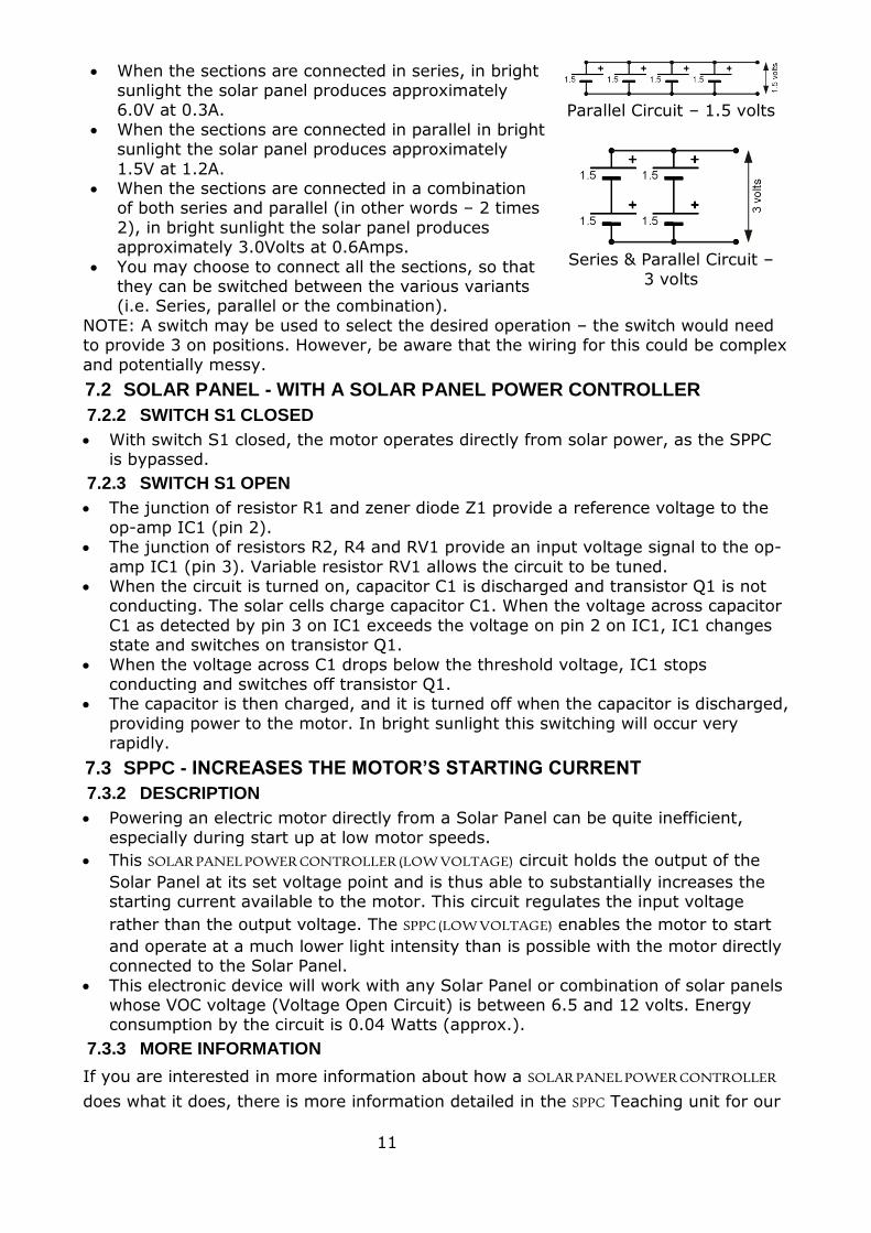
When the sections are connected in series, in bright sunlight the solar panel produces approximately 6.0V at 0.3A.
When the sections are connected in parallel in bright sunlight the solar panel produces approximately
1.5V at 1.2A. When the sections are connected in a combination
of both series and parallel (in other words – 2 times
2), in bright sunlight the solar panel produces approximately 3.0Volts at 0.6Amps.
You may choose to connect all the sections, so that they can be switched between the various variants (i.e. Series, parallel or the combination).
Parallel Circuit – 1.5 volts
Series & Parallel Circuit –
3 volts
NOTE: A switch may be used to select the desired operation – the switch would need to provide 3 on positions. However, be aware that the wiring for this could be complex
and potentially messy.
7.2 SOLAR PANEL - WITH A SOLAR PANEL POWER CONTROLLER
7.2.2 SWITCH S1 CLOSED
With switch S1 closed, the motor operates directly from solar power, as the SPPC is bypassed.
7.2.3 SWITCH S1 OPEN
The junction of resistor R1 and zener diode Z1 provide a reference voltage to the
op-amp IC1 (pin 2). The junction of resistors R2, R4 and RV1 provide an input voltage signal to the op-
amp IC1 (pin 3). Variable resistor RV1 allows the circuit to be tuned. When the circuit is turned on, capacitor C1 is discharged and transistor Q1 is not
conducting. The solar cells charge capacitor C1. When the voltage across capacitor
C1 as detected by pin 3 on IC1 exceeds the voltage on pin 2 on IC1, IC1 changes state and switches on transistor Q1.
When the voltage across C1 drops below the threshold voltage, IC1 stops conducting and switches off transistor Q1.
The capacitor is then charged, and it is turned off when the capacitor is discharged,
providing power to the motor. In bright sunlight this switching will occur very rapidly.
7.3 SPPC - INCREASES THE MOTOR’S STARTING CURRENT
7.3.2 DESCRIPTION
Powering an electric motor directly from a Solar Panel can be quite inefficient,
especially during start up at low motor speeds.
This SOLAR PANEL POWER CONTROLLER (LOW VOLTAGE) circuit holds the output of the
Solar Panel at its set voltage point and is thus able to substantially increases the starting current available to the motor. This circuit regulates the input voltage
rather than the output voltage. The SPPC (LOW VOLTAGE) enables the motor to start
and operate at a much lower light intensity than is possible with the motor directly connected to the Solar Panel.
This electronic device will work with any Solar Panel or combination of solar panels whose VOC voltage (Voltage Open Circuit) is between 6.5 and 12 volts. Energy consumption by the circuit is 0.04 Watts (approx.).
7.3.3 MORE INFORMATION
If you are interested in more information about how a SOLAR PANEL POWER CONTROLLER
does what it does, there is more information detailed in the SPPC Teaching unit for our

12
normal voltage unit – the standard voltage SPPC was designed for use in the Model Solar Car Challenge – more information about that is available on the web site www.solarnational.org).