
Advanced Orbital Pipe Welding - CORE · PDF fileAdvanced Orbital Pipe Welding ... Furthermore,...
140
Faculty of Technology Mechanical Engineering Laboratory of Welding Technology Hamidreza Latifi Advanced Orbital Pipe Welding Supervisors: Professor Jukka Martikainen Dr. (Tech.) Paul Kah
Transcript of Advanced Orbital Pipe Welding - CORE · PDF fileAdvanced Orbital Pipe Welding ... Furthermore,...
Faculty of Technology
Mechanical Engineering
Laboratory of Welding Technology
Hamidreza Latifi
Advanced Orbital Pipe Welding
Supervisors: Professor Jukka Martikainen
Dr. (Tech.) Paul Kah
i
ABSTRACT
Author: Hamidreza Latifi
Title of thesis: Advanced orbital pipe welding
Faculty: Faculty of Technology
Year: 2012
Master’s Thesis Lappeenranta University of Technology
126 pages, 60 figures, and 4 tables
Examiners: Prof. Jukka Martikainen
Dr. (Tech.) Paul Kah
Keywords: Pipe welding, adaptive, orbital, seam tracking,
vision sensor.
Since the introduction of automatic orbital welding in pipeline application in 1961,
significant improvements have been obtained in orbital pipe welding systems.
Requirement of more productive welding systems for pipeline application forces
manufacturers to innovate new advanced systems and welding processes for orbital
welding method.
Various methods have been used to make welding process adaptive, such as visual
sensing, passive visual sensing, real-time intelligent control, scan welding technique,
multi laser vision sensor, thermal scanning, adaptive image processing, neural
network model, machine vision, and optical sensing. Numerous studies are reviewed
and discussed in this Master’s thesis and based on a wide range of experiments which
already have been accomplished by different researches the vision sensor are reported
to be the best choice for adaptive orbital pipe welding system.
Also, in this study the most welding processes as well as the most pipe variations
welded by orbital welding systems mainly for oil and gas pipeline applications are
ii
explained. The welding results show that Gas Metal Arc Welding (GMAW) and its
variants like Surface Tension Transfer (STT) and modified short circuit are the most
preferred processes in the welding of root pass and can be replaced to the Gas
Tungsten Arc Welding (GTAW) in many applications. Furthermore, dual-tandem gas
metal arc welding technique is currently considered the most efficient method in the
welding of fill pass.
Orbital GTAW process mostly is applied for applications ranging from single run
welding of thin walled stainless tubes to multi run welding of thick walled pipes. Flux
cored arc welding process is faster process with higher deposition rate and recently
this process is getting more popular in pipe welding applications. Also, combination
of gas metal arc welding and Nd:YAG laser has shown acceptable results in girth
welding of land pipelines for oil and gas industry.
This Master’s thesis can be implemented as a guideline in welding of pipes and tubes
to achieve higher quality and efficiency. Also, this research can be used as a base
material for future investigations to supplement present finding.
iii
ACKNOWLEDGEMENT
This Master’s thesis has been carried out at the Laboratory of Welding Technology of
the Department of Mechanical Engineering in Lappeenranta University of
Technology, Finland. This study started in February 2012 and completed in
November 2012.
First, I would like to thank God for giving me the strength, courage, and health to do
this project work. The author wishes to express sincere appreciation to the laboratory
and welding department, where this project work was done for their guidance and
financial support.
Most importantly, I am heartily thankful to my professor, Jukka Martikainen, whose
encouragement, supervision and support from the preliminary to the concluding level
enabled me to develop an understanding of the subject. It gives me great pleasure in
acknowledging the support and help of Dr. (Tech.) Paul Kah, whose expertise,
understanding and patient added considerably to my research experience.
Finally, I would like to say this thesis would never have been completed without the
encouragement and devotion of my parents and my two sisters. I greatly appreciate
their unending love and support.
Hamidreza Latifi
Lappeenranta
2012
iv
Background
Orbital welding was developed at the beginning of the 1960s by the aerospace and
nuclear power industries to provide the basic conditions to manufacture highly
reliable components [1, 2, 3, 4, 5]. The first orbital welding system was a mechanism
of rotating tungsten electrode that produced welding arc around a tube weld joint. The
system was supported by a controlling system for entire process by which obtained
result was more precise and reliable than manual welding [3]. The first use of
mechanized orbital welding of cross-country pipelines with carbon dioxideprocess
was laid in the US in 1961 and at the same time five different orbital Gas Metal Arc
Welding (GMAW) processes were under research and development [6, 7].
By the early 1980s, Orbital welding became practical for many industries thanks to
the development of portable combination power supply/control systems by reducing
the size of equipment. The portability of equipment made multiple in-place welds
possible around construction sites [3, 4]. In the late 1990s, improvement of
microprocessor technology leads orbital welding to the position of a cost effective
and preferred method of making connections provides more welding options for
welders of different skill levels [5].
Nowadays, orbital pipe welding is one of the key methods applied in almost every
industry, such as food, dairy, beverage, power, chemical, oil and gas, pulp and paper,
etc. [1, 8]. However, in some developing countries, this method of welding is still
quite new and has not been in use so often.
v
Contents
ABSTRACT .............................................................................................................. i
ACKNOWLEDGEMENT ....................................................................................... iii
Background ............................................................................................................. iv
List of Symbols and Abbreviations ......................................................................... vii
List of Figures .......................................................................................................... x
1. Introduction .......................................................................................................... 1
1.1. The Objective of the Work ............................................................................. 3
2. Pipe Welding ........................................................................................................ 3
2.1. Variation of Mechanized Pipe Welding .......................................................... 4
2.1.1. Stationary Pipe Welding .......................................................................... 4
2.1.2. Circular Pipe Welding (Orbital) ............................................................... 5
2.2. Submerged Arc Welding (SAW) .................................................................... 5
3. Orbital Pipe Welding ............................................................................................ 8
3.1. Advantages of Orbital Pipe Welding .............................................................. 9
3.2. Fundamental of Orbital Pipe Welding ...........................................................10
3.2.1. Closed Head Mechanism (Full Function in Place)...................................11
3.2.2. Open Head Mechanism (Full Function Orbital) ......................................12
3.3 Properties of Pipe ...........................................................................................14
3.3.1. Possible Pipe Materials in Orbital welding..............................................15
3.3.2. Materials Weldability for Oil and Gas Applications ................................15
3.4. Various Welding Phase Types in Orbital Pipe Welding .................................18
3.5. Various Welding Groove Types in Orbital Pipe Welding ..............................20
3.6. Orbital Welding Parameters and Equipment ..................................................22
vi
3.6.1. Power Source .........................................................................................23
3.6.2. Filler Wire ..............................................................................................25
3.6.3. Shielding Gas .........................................................................................29
4. Adaptive Orbital Pipe Welding ............................................................................29
5. Most Used Welding Processes in Orbital Pipe Welding........................................31
5.1. Gas Tungsten Arc Welding (GTAW) ............................................................33
5.2. Flux Cored Arc Welding (FCAW).................................................................39
5.3. Gas Metal Arc Welding (GMAW).................................................................42
5.3.1. Tandem Gas Metal Arc Welding (T-GMAW) .........................................48
5.3.2. Dual-Tandem Gas Metal Arc Welding (DT-GMAW) .............................49
5.3.3. Narrow Groove Tandem Gas Metal Arc Welding (NG-TGMAW) ..........52
5.3.4. Twin Wire Gas Metal Arc Welding (TW-GMAW) .................................53
5.3.5. Double Electrode Gas Metal Arc Welding (DE-GMAW) .......................53
5.3.6. Modified Short Circuit Gas Metal Arc Welding ......................................56
5.3.7. Pulsed Gas Metal Arc Welding (P-GMAW) ...........................................58
5.3.8. Rapid Arc ...............................................................................................61
5.3.9. Surface Tension Transfer (STT) .............................................................63
5.4. Laser Welding and Hybrid Laser Arc Welding ..............................................66
6. Seam Tracking in Orbital Pipe Welding ...............................................................80
7. Weld Quality Test and Control .............................................................................92
8. Investments and Economies in Orbital Pipe Welding ...........................................95
9. Future Studies ......................................................................................................95
10. Summary and Conclusions .................................................................................96
References ............................................................................................................. 101
vii
List of Symbols and Abbreviations
A Ampere
AC Alternating Current
ACC Accelerated Cooling
API American Petroleum Institute
Ar Argon
ASME American Society of Mechanical Engineers
BPE BioProcessing Equipment
CC Constant Current
CCD Charge Coupled Device
CCW Counterclockwise
cm Centimeter
CO Carbon monoxide
CO� Carbon dioxide
CPT Critical Pitting Temperature
Cr Chromium
CTOD Crack Tip Opening Displacement
CV Constant Voltage
CVN Charpy V-Notch
CW Clockwise
DC Direct Current
DE-GMAW Double Electrode Gas Metal Arc Welding
DT-GMAW Dual Tandem Gas Metal Arc Welding
El Elongation
EWI Edison Welding Institute
FCAW Flux Cored Arc Welding
GMAW Gas Metal Arc Welding
GTAW Gas Tungsten Arc Welding
HAZ Heat Affected Zone
He Helium
viii
HLAW Hybrid Laser Arc Welding
ID Inside
J Joule
kg/hr Kilogram per hour
kHz Kilohertz
kJ/mm Kilojoule per millimeter
kW Kilowatt
LNG Liquid Natural Gas
m Meter
m/min Meter per minute
MAG Metal Active Gas
MIG Metal Inert Gas
MJ-6 Material Joining-Weld Acceptance Criteria
mm Millimeter
mm/s Millimeter per second
Mn Manganese
Mo Molybdenum
MPa Megapascal
μm Micrometer
Nd:YAG Neodymium-doped: Yttrium Aluminum Garnet
NG-TGMAW Narrow-Groove Tandem Gas Metal Arc Welding
Ni Nickel
OD Outside
P Phosphorus
PAW Plasma Arc Welding
P-GMAW Pulsed Gas Metal Arc Welding
PQR Procedure Qualification Record
PS Pressure Strength
Rm Tensile strength
Rp0.2 Yield point 0.2 %
S Sulfur
ix
SAW Submerged Arc Welding
SMAW Shielded Metal Arc Welding
STT Surface Tension Transfer
T-GMAW Tandem Gas Metal Arc Welding
TIG Tungsten Inert Gas
T.I.M.E Transferred Ionized Molten Energy
TM Thermo-Mechanical
T-SAW Tandem Submerged Arc Welding
TS Tensile Strength
TW-GMAW Twin Wire Gas Metal Arc Welding
TWI The Welding Institute
UK United Kingdom
US$ United States Dollar
USA United States of America
USSR Union of Soviet Socialist Republics
V Voltage
WOPQ Welding Operator Performance Qualifications
WPS Welding Procedure Specification
Yb Ytterbium
5G Horizontal fixed Groove
℃ Degree Celsius
x
List of Figures
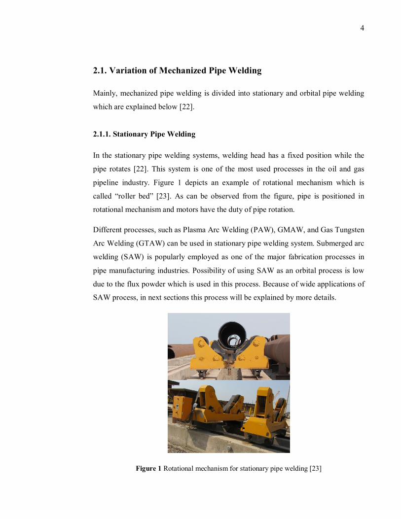
Figure 1 Rotational mechanism for stationary pipe welding [23] ............................... 4
Figure 2 Column and boom manipulator use with SAW process [23] ........................ 7
Figure 3 (a) Root pass welding of carbon steel pipe with SMAW process (b) the final
weld bead with several passes done by column and boom manipulator SAW process
[23] ........................................................................................................................... 8
Figure 4 Standard enclosed orbital weld heads can be used to weld tube size from 1.6
mm up to 152.4 mm and wall thicknesses up to 4 mm [4] ......................................... 9
Figure 5 (a) Manual welded process tube (b) Orbital welded process tube [51] ........10
Figure 6 Open head welding machine for welding of pipes with large diameter [52] 11
Figure 7 Principle of orbital GTAW process [2] .......................................................12
Figure 8 Development of pipeline steels [73] ...........................................................17
Figure 9 Microstructure of high strength pipeline steels: (a) X70, (b) X80, (c) X100
[73] ..........................................................................................................................18
Figure 10 Type definition of weld groove, (a) V-groove (b) U-groove [30] ..............19
Figure 11 (a) Welding of hot pass (b) Typical weld appearance of a mechanized weld
joint [81] ..................................................................................................................20
Figure 12 Various possible narrow-gap GTA welds [84] ..........................................21
Figure 13 Mechanized orbital GTAW of austenitic piping; axial shrinkage at outer
surface as function of number of passes and comparison of various weld types [100]
................................................................................................................................35
Figure 14 Comparison of cross sectional areas of pipe welding groove. Groove
dimensions: normal U (included angle 30°, radius 3 mm and root face 2 mm) and
narrow-gap groove (included angle 4 degrees, radius 3 mm and root face 2 mm) [22]
................................................................................................................................36
Figure 15 Schematic representation of the use of GTAW welds for inside of pipe and
Rapid arc welds for outside [78] ..............................................................................37
Figure 16 This drawing shows typical representations of the arc shape and resultant
weld profile for various electrode tapers [4] .............................................................39
xi
Figure 17 Orbital FCAW is a high deposition rate process (3.63 kg/hr), suitable for
welding large diameter, heavy wall pipe [111, 112] .................................................40
Figure 18 A standard V bevel is made with STT root and FCAW fill passes [111,
112] .........................................................................................................................41
Figure 19 Required equipment for the economically efficient use of orbital GMAW
[128] ........................................................................................................................44
Figure 20 The pipeline and welding cabins (a), the welding robots inside the cabins (b
and c) [129, 130] ......................................................................................................45
Figure 21 Root run in X80 pipe made using a controlled dip process [16] ................47
Figure 22 Microstructure of root pass of VP-GMAW process [16] ...........................48
Figure 23 Arrangement of Cranfield automated pipe welding torches and system [16,
55] ...........................................................................................................................50
Figure 24 (a) Cranfield automated pipe welding system’s macro-section and (b) weld
bevel from weld in 14.9 mm wall X100 pipeline [16, 55] .........................................50
Figure 25 Cooling curves for an external plunged thermocouple with various GMAW
pipeline welding systems [16] ..................................................................................51
Figure 26 Cooling curves for an internal thermocouple with GMAW pipeline welding
systems [16].............................................................................................................52
Figure 27 Non-consumable DE-GMAW system [124, 144] .....................................54
Figure 28 Proposed consumable DE-GMAW system [144, 155] ..............................55
Figure 29 Welding gun arrangement of consumable DE-GMAW process [144, 156]
................................................................................................................................56
Figure 30 Comparison of root passes performed by modified short circuit GMAW
(a), GTAW (b), and traditional short circuit GMAW (c) [104] .................................57
Figure 31 Pulsing current for metal transfer [126] ....................................................59
Figure 32 Schematic illustration of pulsed GMAW process [57] ..............................60
Figure 33 Schematic of Rapid arc’s waveform and its principle [78] ........................62
Figure 34 Schematic of STT wave form and principle of STT process in one cycle
[167] ........................................................................................................................64
Figure 35 Cross section of one pass hybrid laser arc welding on a carbon steel square
butt joint [175] .........................................................................................................71
xii
Figure 36 Hybrid laser welding combines the attribute of GMAW and laser beam
welding [149] ..........................................................................................................73
Figure 37 Formation of the weld in hybrid welding [180] ........................................73
Figure 38 Welds: laser welding (a), GMAW (b), laser-arc hybrid welding (c) [189] .74
Figure 39 Welding head with hybrid equipment for root pass welding and arc torch
for filler pass welding [180] .....................................................................................75
Figure 40 Macro-section of the pipeline steel X52 welded joints 10 mm thick at speed
of hybrid of (a) 1.0 and (b, c) 0.8 m/min [194] ........................................................75
Figure 41 Cross section of hybrid welding at 0.0381 m/s (a) root pass welding (b)
root pass plus hot pass welding [12] .........................................................................76
Figure 42 Section through pipe wall, showing internal GMAW root run, 9.0 kW
autogenous laser fill and GMAW capping pass [196] ...............................................77
Figure 43 (a) HL-GMAW root with GMAW fill (b) IWM root pass with HL-GMAW
first fill [16] .............................................................................................................78
Figure 44 Block diagram of the pipe welding system [204] ......................................81
Figure 45 The four welding positions in the orbital pipe welding [207, 208] ............81
Figure 46 Welding torch degree of freedom [208] ....................................................82
Figure 47 Visual inspection system [215].................................................................83
Figure 48 Schematic of welding system and manipulator [216] ................................85
Figure 49 (a) Features extraction in weld pool image, (b) weld pool image [199] .....86
Figure 50 Result of weld pool control: (a) with control; (b) without control [199] ....87
Figure 51 Outline of circumferential GTA welding of steel pipe [221] .....................87
Figure 52 A simplified orbital welding arrangement [222] .......................................88
Figure 53 Process diagram of an automatic orbital GTA welding of pipes with CCD
[9] ............................................................................................................................89
Figure 54 Result of welding pool for pipes (front face) [9] .......................................89
Figure 55 (a) Macrograph of a grooved weld at 12 O’clock location. (b) Fusion zone
section at 12 O’clock [9] ..........................................................................................90
Figure 56 (a) Macrograph of a grooved weld at 3 O’clock location (downward). (b)
Fusion zone section at 3 O’clock [9] ........................................................................90
xiii
Figure 57 (a) Macrograph of a grooved weld at 6 O’clock location (overhead
position). (b) Fusion zone section at 6 O’clock [9] ...................................................91
Figure 58 (a) Macrograph of a grooved weld at 9 O’clock location (upward). (b)
Fusion zone section at 9 O’clock [9] ........................................................................91
Figure 59 Ovality after welding [10] ........................................................................93
Figure 60 Flow chart for orbital welding/inspection/documentation of welds [228] ..94
1
1. Introduction
Pipes and tubes welding are widely used in almost every engineering application,
such as nuclear and thermal power plants, semiconductor fabrications, oil and gas
industries, and petrochemical plants. Therefore, the welding quality of pipelines has a
direct effect on the public safety and quality of the products [9, 10]. Oil and gas
industry will be one of the key industries demanding extensive pipe welding due to
the prediction of a doubling of natural gas consumption over the next 20 years [11,
12]. This increscent in requirements of pipe welding will require major investment in
gas transmission pipelines. Trend of using gas transmission with higher operating
pressure and higher strength steels increased demand of higher weld metals toughness
and quality. On the other hand, the cost of pipelines constructed should be considered
to be as low as possible.
Various automatic welding processes have been developed in pipe welding industries
to speed up welding process, producing better weld quality, and reducing welding
cost [12]. Also, development in orbital pipe welding technology helps to maximize
the productivity of available welders and make welding process easier by employing
a variety of automated features, such as data collection, programming, and live weld
progress [11, 13]. Different factors, such as gravity, arc force, surface tension, heat
accumulation, joint preparation, and fit up precision effect welding pool during
automatic orbital pipe welding. Therefore, need of feedback and controlling system is
a vital part of orbital pipe system to ensure high welding quality [9].
Orbital welding is finding increasing value because it can present a cleaner, virtually
crevice surface and deliver highly repeatable and consistent quality welds.
Consequently, today, orbital welding has become a practical tool for many plant and
industrial operations due to the advanced technology [5]. These industries can be
named as, boiler tube, food, dairy and beverage industries, nuclear piping, offshore,
tube/pipe fitting, valve, regulators, power, chemical, oil and gas, aerospace,
biopharmaceutical, medical, semiconductor, and pulp and paper industries, and for
2
use in construction, plant maintenance, distillation and refining operations [1, 3, 4,
14, 15].
By 2003 in all around the world, almost 20,000 km of pipelines were completed at
total cost of US$15 billion. 60 % of this number belongs to the natural gas pipelines
[16]. Recently, significant improvements have been obtained in adaptive orbital pipe
welding system. Various studies have been done in weld pool geometry sensing,
modeling and intelligent control of the weld quality, and process monitoring. In this
research work, the most typical welding processes used in orbital pipe welding as
well as adaptive controlling system of orbital pipe welding are explained.
3
1.1. The Objective of the Work
Due to the fact that standards are getting more stringent in pipelines welding, all
joints are required to be uniform and it is difficult for the welder to comply with these
requirements [17]. Also, by growth of pipe welding applications, the need of orbital
pipe welding process with higher productivity, greater weld quality, lower cost, and
accuracy in manufacturing is sensed more than before. In this case, an adaptive
orbital pipe welding system provides dramatic improvements over existing methods
[18, 19, 20]. The main objectives of this thesis work are to:
Introduce mechanized pipe welding and its variation
Explain orbital pipe welding and its variation
Explain applications of orbital pipe welding
List advantages/disadvantages of orbital pipe welding
Explain properties of possible pipe’s materials for orbital welding applications
List the most used pipes in orbital welding especially for oil and gas pipelines
Explain the most used welding processes for orbital pipe welding
Explain adaptive orbital pipe welding
Explain seam tracking in orbital pipe welding
Investigate the economical aspect of using orbital pipe welding
2. Pipe Welding
Welding which is used in pipelines, typically is divided into mainline welding, tie-in
welding, and repair welding. Speed in mainline welding is critical factor and there is
access for backing system, but in Tie-in and repair welding there is no access to the
inside of pipe and speed is less important [21]. In this study, adaptive orbital pipe
welding of mainline will be explained with different processes.
4
2.1. Variation of Mechanized Pipe Welding
Mainly, mechanized pipe welding is divided into stationary and orbital pipe welding
which are explained below [22].
2.1.1. Stationary Pipe Welding
In the stationary pipe welding systems, welding head has a fixed position while the
pipe rotates [22]. This system is one of the most used processes in the oil and gas
pipeline industry. Figure 1 depicts an example of rotational mechanism which is
called “roller bed” [23]. As can be observed from the figure, pipe is positioned in
rotational mechanism and motors have the duty of pipe rotation.
Different processes, such as Plasma Arc Welding (PAW), GMAW, and Gas Tungsten
Arc Welding (GTAW) can be used in stationary pipe welding system. Submerged arc
welding (SAW) is popularly employed as one of the major fabrication processes in
pipe manufacturing industries. Possibility of using SAW as an orbital process is low
due to the flux powder which is used in this process. Because of wide applications of
SAW process, in next sections this process will be explained by more details.
Figure 1 Rotational mechanism for stationary pipe welding [23]
5
2.1.2. Circular Pipe Welding (Orbital)
In this pipe welding method, the welding head rotates around a fixed vertical or
horizontal pipe [22]. Moving of electrode circumferentially around the pipe has more
advantages compared to the stationary pipe welding [24]. This type of pipe welding
which is main part of this study will be explained by detail.
Pipe Fixing Mechanism in Orbital Welding
Fixing of pipe in orbital pipe welding system is an important factor due to the
sensitiveness of precision in this system. Small positioning error may lead to
incomplete or misaligned weld and growth of welding cost by re-welded or cut out of
the weld [14].
2.2. Submerged Arc Welding (SAW)
SAW is an arc welding process that established arc between a consumable electrode
and the weld pool heats workpiece to join them. In this process fluxed powder used to
cover and shield both, the arc and molten weld [25].
There are several advantages involved with SAW process, such as deep penetration,
relatively free of the intense radiation of heat and light, free of spatter, welding of
very thick sections at low velocities, high efficiency, a smooth bead, availability in
automatic or semi-automatic mode, and good reliability [26, 27, 28]. On the other
hand, there are few limitations of using SAW process. SAW is limited to flat and
horizontal positions welding due to the effect of gravity [26]. A full time operator is
needed in welding of pipe, pressure vessel, and ship structure by SAW, although this
process is typically a mechanized process [29, 30]. In pipe welding applications by
SAW, finding suitable values for the process parameters to obtain a desired quality
and bead geometry is not easy work [31, 32]. This welding process requires work
pieces to be rotated under a fixed torch. Also, this method requires considerable
6
capital expenditures for turning rolls and positioners, especially if the pipe work
consists of larger-diameter pipe, long lengths and heavy assemblies [33].
The benefits of SAW process make this process robust in the fabrication of pressure
vessels, marine vessels, pipelines and offshore structures [28]. Improving the
deposition rate of SAW process has been always the main issue and lots of effort has
been done to achieve this purpose. Higher deposition rate can be obtained by
increasing heat input. One way is using Tandem Submerged Arc Welding (T-SAW)
[34] by twin arc mode [35, 36] or multi wires (four-wire) which is becoming more
popular in longitudinal seam pipe production and leads to higher proficiency [37],
and another way is adding metal powders [38, 39].
Beside productivity, bead geometry such as adequate penetration is an important
factor in welding process [40]. Possibility of obtaining poor bead geometry is always
high due to the demand of deeper penetration. Therefore, having knowledge of
changing a particular parameter on the bead geometry is an important issue and many
efforts have been made to correlate the bead geometry with the welding parameters
[41, 42, 43].
In the study [40], the author used software developed at Carlton University [44] to
predict the weld bead geometry for SAW process. The following conclusion can be
listed from the study:
Four methods can be used to increase melting rate of SAW process which are;
higher current, straight polarity, smaller diameter of electrode, and longer
electrode extension.
Current level and polarity influence the percentage difference in melting rate,
bead width, bead height, and bead penetration.
The reduction in electrode diameter increases the melting rate, bead height,
and penetration.
There is a linear relation between electrode extension and current. Bigger
electrode extension at low current raises bead height and penetration.
7
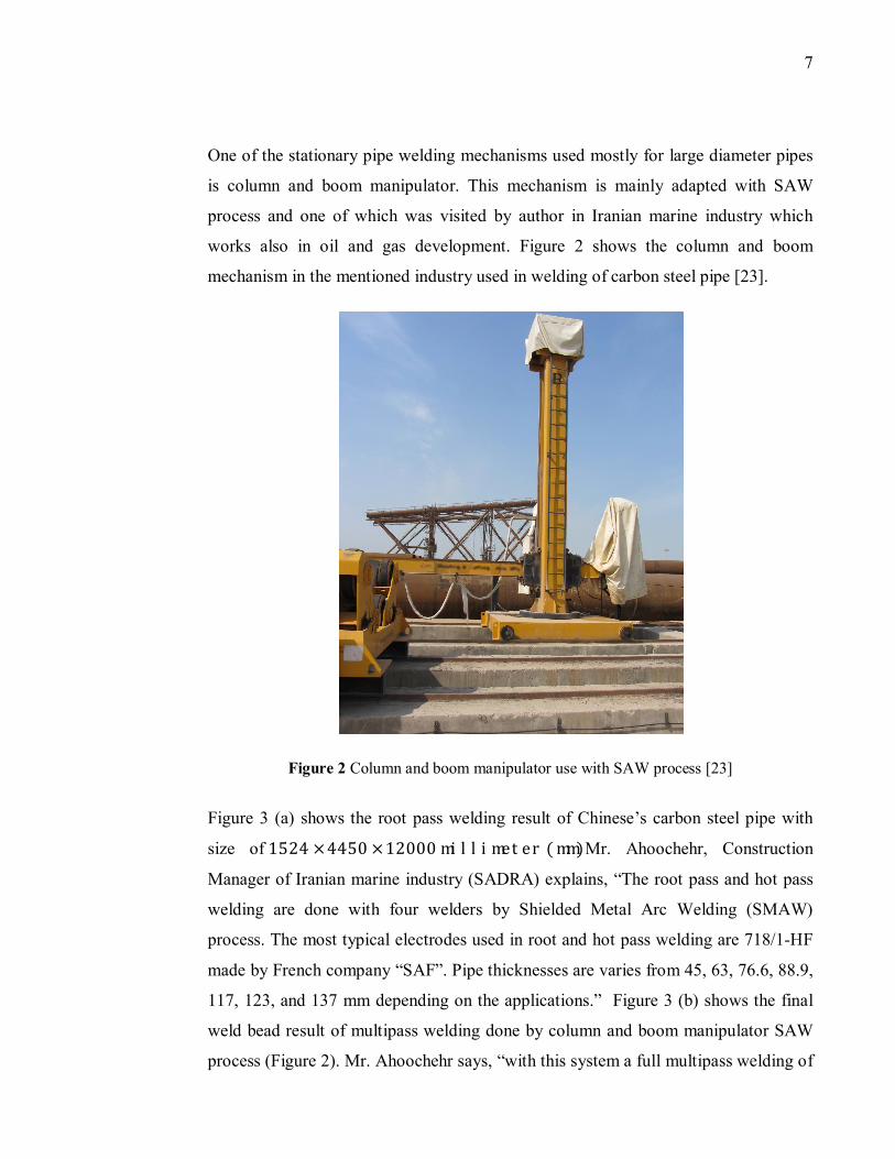
One of the stationary pipe welding mechanisms used mostly for large diameter pipes
is column and boom manipulator. This mechanism is mainly adapted with SAW
process and one of which was visited by author in Iranian marine industry which
works also in oil and gas development. Figure 2 shows the column and boom
mechanism in the mentioned industry used in welding of carbon steel pipe [23].
Figure 2 Column and boom manipulator use with SAW process [23]
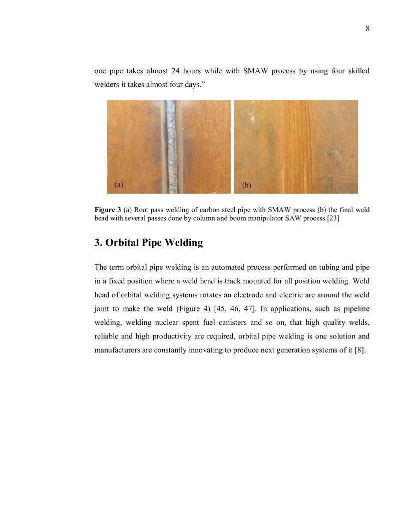
Figure 3 (a) shows the root pass welding result of Chinese’s carbon steel pipe with
size of1524 × 4450 × 12000millimeter(mm). Mr. Ahoochehr, Construction
Manager of Iranian marine industry (SADRA) explains, “The root pass and hot pass
welding are done with four welders by Shielded Metal Arc Welding (SMAW)
process. The most typical electrodes used in root and hot pass welding are 718/1-HF
made by French company “SAF”. Pipe thicknesses are varies from 45, 63, 76.6, 88.9,
117, 123, and 137 mm depending on the applications.” Figure 3 (b) shows the final
weld bead result of multipass welding done by column and boom manipulator SAW
process (Figure 2). Mr. Ahoochehr says, “with this system a full multipass welding of
8
one pipe takes almost 24 hours while with SMAW process by using four skilled
welders it takes almost four days.”
Figure 3 (a) Root pass welding of carbon steel pipe with SMAW process (b) the final weld bead with several passes done by column and boom manipulator SAW process [23]
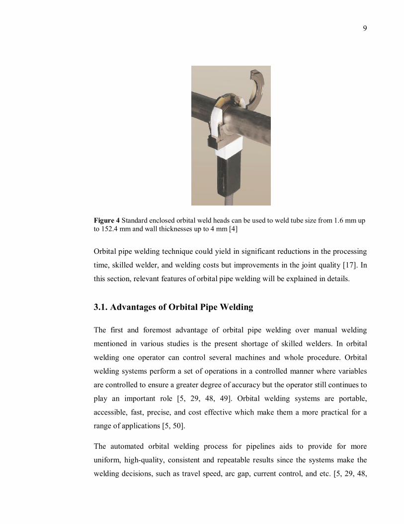
3. Orbital Pipe Welding
The term orbital pipe welding is an automated process performed on tubing and pipe
in a fixed position where a weld head is track mounted for all position welding. Weld
head of orbital welding systems rotates an electrode and electric arc around the weld
joint to make the weld (Figure 4) [45, 46, 47]. In applications, such as pipeline
welding, welding nuclear spent fuel canisters and so on, that high quality welds,
reliable and high productivity are required, orbital pipe welding is one solution and
manufacturers are constantly innovating to produce next generation systems of it [8].
9
Figure 4 Standard enclosed orbital weld heads can be used to weld tube size from 1.6 mm up to 152.4 mm and wall thicknesses up to 4 mm [4]
Orbital pipe welding technique could yield in significant reductions in the processing
time, skilled welder, and welding costs but improvements in the joint quality [17]. In
this section, relevant features of orbital pipe welding will be explained in details.
3.1. Advantages of Orbital Pipe Welding
The first and foremost advantage of orbital pipe welding over manual welding
mentioned in various studies is the present shortage of skilled welders. In orbital
welding one operator can control several machines and whole procedure. Orbital
welding systems perform a set of operations in a controlled manner where variables
are controlled to ensure a greater degree of accuracy but the operator still continues to
play an important role [5, 29, 48, 49]. Orbital welding systems are portable,
accessible, fast, precise, and cost effective which make them a more practical for a
range of applications [5, 50].
The automated orbital welding process for pipelines aids to provide for more
uniform, high-quality, consistent and repeatable results since the systems make the
welding decisions, such as travel speed, arc gap, current control, and etc. [5, 29, 48,
10
49, 50]. Also, higher productivity, higher welding speed, lower distortion, well-
documented, controlled and limited heat input which lead to lower Heat Affected
Zone (HAZ) are further advantages of orbital pipe welding [11, 12, 48, 50]. The
number of defects minimized and program can be repeated several times without
mistakes [11].
Manual welding is slower and subject to human error with inconsistent results,
although the welder may be highly skilled and experienced [5, 50]. Manual welding
needs more space around the pipe to provide welders enough clearance for full body
access to the weld location with switch position and repeatedly starting and stopping
[5, 11]. Another disadvantage of manual welding is documentation, which may not be
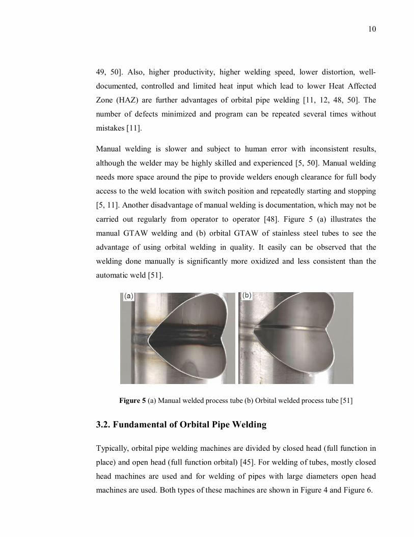
carried out regularly from operator to operator [48]. Figure 5 (a) illustrates the
manual GTAW welding and (b) orbital GTAW of stainless steel tubes to see the
advantage of using orbital welding in quality. It easily can be observed that the
welding done manually is significantly more oxidized and less consistent than the
automatic weld [51].
Figure 5 (a) Manual welded process tube (b) Orbital welded process tube [51]
3.2. Fundamental of Orbital Pipe Welding
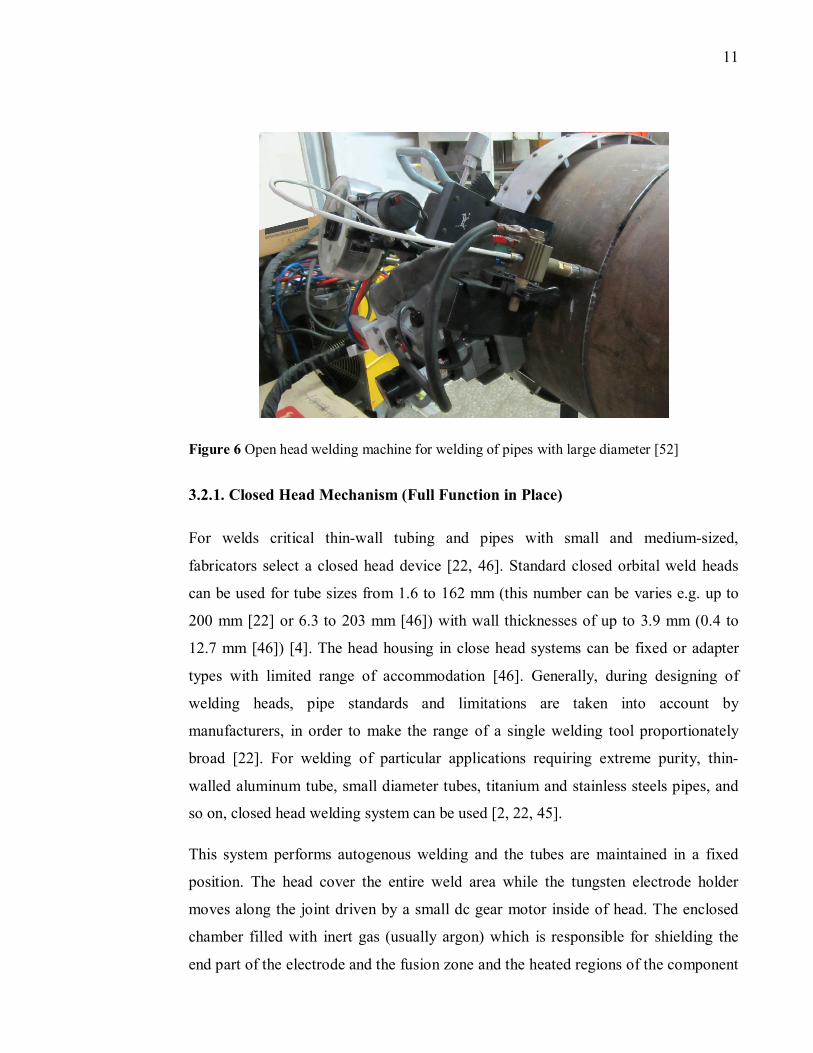
Typically, orbital pipe welding machines are divided by closed head (full function in
place) and open head (full function orbital) [45]. For welding of tubes, mostly closed
head machines are used and for welding of pipes with large diameters open head
machines are used. Both types of these machines are shown in Figure 4 and Figure 6.
11
Figure 6 Open head welding machine for welding of pipes with large diameter [52]
3.2.1. Closed Head Mechanism (Full Function in Place)
For welds critical thin-wall tubing and pipes with small and medium-sized,
fabricators select a closed head device [22, 46]. Standard closed orbital weld heads
can be used for tube sizes from 1.6 to 162 mm (this number can be varies e.g. up to
200 mm [22] or 6.3 to 203 mm [46]) with wall thicknesses of up to 3.9 mm (0.4 to
12.7 mm [46]) [4]. The head housing in close head systems can be fixed or adapter
types with limited range of accommodation [46]. Generally, during designing of
welding heads, pipe standards and limitations are taken into account by
manufacturers, in order to make the range of a single welding tool proportionately
broad [22]. For welding of particular applications requiring extreme purity, thin-
walled aluminum tube, small diameter tubes, titanium and stainless steels pipes, and
so on, closed head welding system can be used [2, 22, 45].
This system performs autogenous welding and the tubes are maintained in a fixed
position. The head cover the entire weld area while the tungsten electrode holder
moves along the joint driven by a small dc gear motor inside of head. The enclosed
chamber filled with inert gas (usually argon) which is responsible for shielding the
end part of the electrode and the fusion zone and the heated regions of the component
12
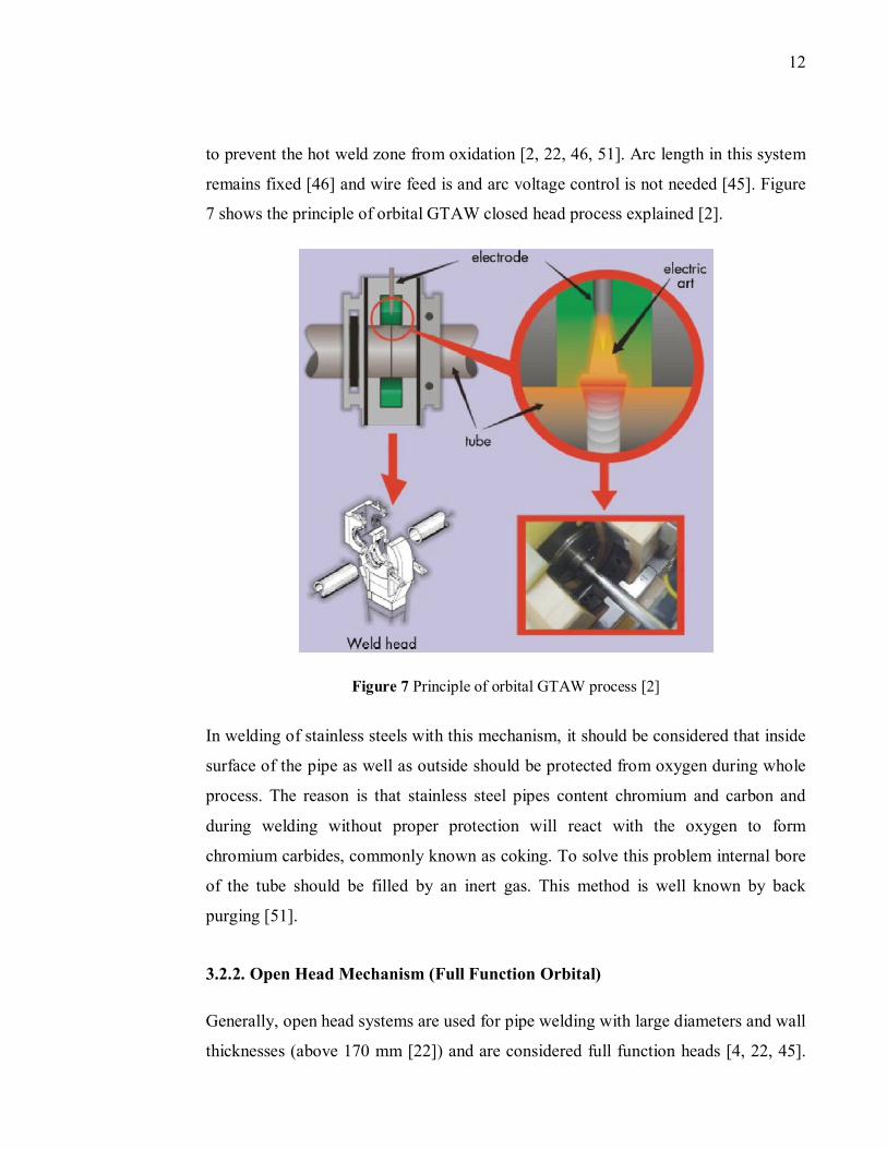
to prevent the hot weld zone from oxidation [2, 22, 46, 51]. Arc length in this system
remains fixed [46] and wire feed is and arc voltage control is not needed [45]. Figure
7 shows the principle of orbital GTAW closed head process explained [2].
Figure 7 Principle of orbital GTAW process [2]
In welding of stainless steels with this mechanism, it should be considered that inside
surface of the pipe as well as outside should be protected from oxygen during whole
process. The reason is that stainless steel pipes content chromium and carbon and
during welding without proper protection will react with the oxygen to form
chromium carbides, commonly known as coking. To solve this problem internal bore
of the tube should be filled by an inert gas. This method is well known by back
purging [51].
3.2.2. Open Head Mechanism (Full Function Orbital)
Generally, open head systems are used for pipe welding with large diameters and wall
thicknesses (above 170 mm [22]) and are considered full function heads [4, 22, 45].
13
There are two approaches for designing of this welding system. In the first one,
within of an external frame the welding heads mounted, introduced since 1960s, and
its main application is on lay barges, planned for the wide, open space of the USA
and USSR. In the second approach, welding system consists of welding head or
“bugs”, bands or chains, power supply, wire feeder, a programmable controller,
shielding gas, and coolant. Bands or chains are a device attached to the pipe or tube to
move the head around the joint. The controller may be mixed into the power supply
and cable for delivery of power. The welding heads mounted on bands or chains and
travels the circumference of the pipe along a track. In welding of thin wall tube,
welding head mostly consists of water cooling system to reduce heat input. The main
application of this welding system is onshore pipelines [7, 22, 46].
By starting welding procedure by operator, the weld head and its inside electrode
house rotates in a precise orbit around the joint. The process is highly controlled, and
there are at least four servo controlled axes (travel, wire, arc voltage control, and
center steering) to ensure high quality welds that can be produced on a consistent and
repeatable basis. Precise controlling of all parameters in welding head requires a
state-of-the-art computer due to the complexity of this welding process [45, 46, 48]. It
takes slightly more time to install these systems than to install an in-place head. This
type also may require a longer straight length of pipe for mounting. In orbital
multipass pipe welding, welding heads typically feature [1]:
1. Torch rotation
2. Filler wire feed capability
3. Electronic control of arc length (arc voltage control)
4. Torch oscillation (weave) capability with programmable width, speed, and
independent end point (sidewall) dwell times.
The direction of welding head will change by changing of applications. If the position
of pipe weld is horizontal (5G) both, a double up and double down technique (6 to 12
O’clock CW, followed by 6 to 12 O’clock CCW) can be used [47]. Also, weave
technique is usually used in the 5G position welding. To ensure complete sidewall
14
fusion, most of available systems are possible to be programmed dwell or delay
period at either end of the oscillation stroke. Orbital pipe welding with oscillation
motion is a useful feature in pipe welding industries [53].
One way to improve productivity in open head mechanism is to mount two welding
torches on one head. The improvement continues by reducing the distance between
two wires and using shared gas and weld pool. In a further development, it has been
proposed to replace the two torches of a system with tandem torches, creating the so-
called “Dual-Tandem” process [54].
3.3 Properties of Pipe
Welding of thick wall pipes has become a key process in several important industrial
areas, including offshore and onshore pipelines, vessel fabrication, and nuclear
industry [29]. The majority of welded steel pipe is produced from coil or plate [55].
Choosing proper pipe for special purposes is a factor that influences the whole job by
minimizing the possible generation of any defects. The first and foremost step is
selecting material of pipe. Factors in choosing ideal pipe for special application are,
pipe wall thickness, outside diameter, and cleanliness. Storage and handle of pipe in
welding industry are important as well and pipes should be stored in a proper weather
condition. Also, dust, moisture, and dirt inside of tube or pipe, makes welding
difficult and costly [14].
The result of experimental test done by UNAMON in 1996s [24] showed orbital
welding are more efficient for the small diameters and thicknesses. Measuring proper
thickness in pipe welding is essential to prevent hardening of the structure in the HAZ
and cold cracking. The greater thickness of the pipeline causes higher cooling rates
[56].
15
3.3.1. Possible Pipe Materials in Orbital welding
Controlling of certain elements, such as sulfur in the composition of material is very
important in welding procedure [14]. Generally, weldability of 300-series stainless
steels with orbital system which used prevalently are good with the exception of the
types 303 which contain high sulfur and 303SE which contain selenium for ease
machining. Weldability of 400-series stainless steels is good, however possibility of
requiring post-weld heat treatment is also high [3]. Recently, usage of high strength
low alloy (HSLA) steels, greatly increased in welding of pressure vessels, tube and
pipes with orbital systems [57].
Titanium and its alloys pipe are using in applications that corrosion resistant and
particular strength are required and can be welded by orbital pipe welding systems
[58, 59]. In Gulfstream pipeline project [60], grades were used for the majority of the
offshore pipeline was APL 5L Grade X70. American Petroleum Institute (API) 5L
X60 pipe with diameter of 406.4 mm was successfully laid recently in the UK sector
of the North Sea [61].
High strength X80 pipe were used for the first time in Europe by 1980s in Germany
using SMAW welding and at almost the same time, Nova Company in Canada used
mechanized pipe welding for X80 pipe [21]. Common X80 steels used in industries
has properties of: 615 Megapascal (MPa) of yield strength, 680 MPa of tensile
strength, 21 % of elongation, 226 HV10 of hardness, and 330 J of Charpy impact
energy at 20℃ [37]. Other high strength steels, such as X90, X100, and X120 are
also possible to be welded by orbital pipe welding system.
3.3.2. Materials Weldability for Oil and Gas Applications
There is a strong demand for gas and oil in the world especially in the fast growing
economies like China and India, which implies continued growth of oil and gas
pipeline installation [62, 63, 64]. Worldwide gas consumption is predicted to be
almost double over 25 years, from almost 2540 trillion liters in 2000 to 4980 trillion
16
liters in 2025 [16]. The main problem of using gas is that many of gas resources
situated in remote locations and transportation of gas from those resources needs long
distance pipelines transmission [62, 63].
Crude oil is a heterogeneous mixture of hydrocarbons with non-hydrocarbon
components which includes alcohols, phenols, sediments, water, salts, sulfur
compounds, acid gases (such as Hydrogen Sulfide H�S), carbon monoxide (CO), etc.
[65, 66]. There is always high level of corrosion possibility in inner surface of pipe
by oil during its movement due to the corroding agents (water and oxygen). Settled
water which contains dissolved salts and acids, in bottom of pipe has corrosion
effects on those parts in the pipeline [66]. Therefore, high level of safety and trust
direct to reduction of cost, highest efficiency, and lowest defects, required in oil and
gas pipeline distribution. So, special attention required in material selection of pipe
and recent research focuses on the fracture toughness property which is a main factor
in the design of oil and gas pipelines [67, 68, 69, 70, 71].
Demand of liquefied gases worldwide, such as Liquid Natural Gas (LNG) which may
be obtained by cooling down methane gas to temperature below -163 ℃ has increased
[72]. Higher pressures and flow levels towards using line pipe of larger diameter
and/or higher operation pressure. To improve operational efficiencies, avoid large
wall thickness of pipe, and cost saving, development of higher strength steel grades
with relatively thinner wall pipe started more than 30 years age [16, 37, 47, 62, 73,
74].
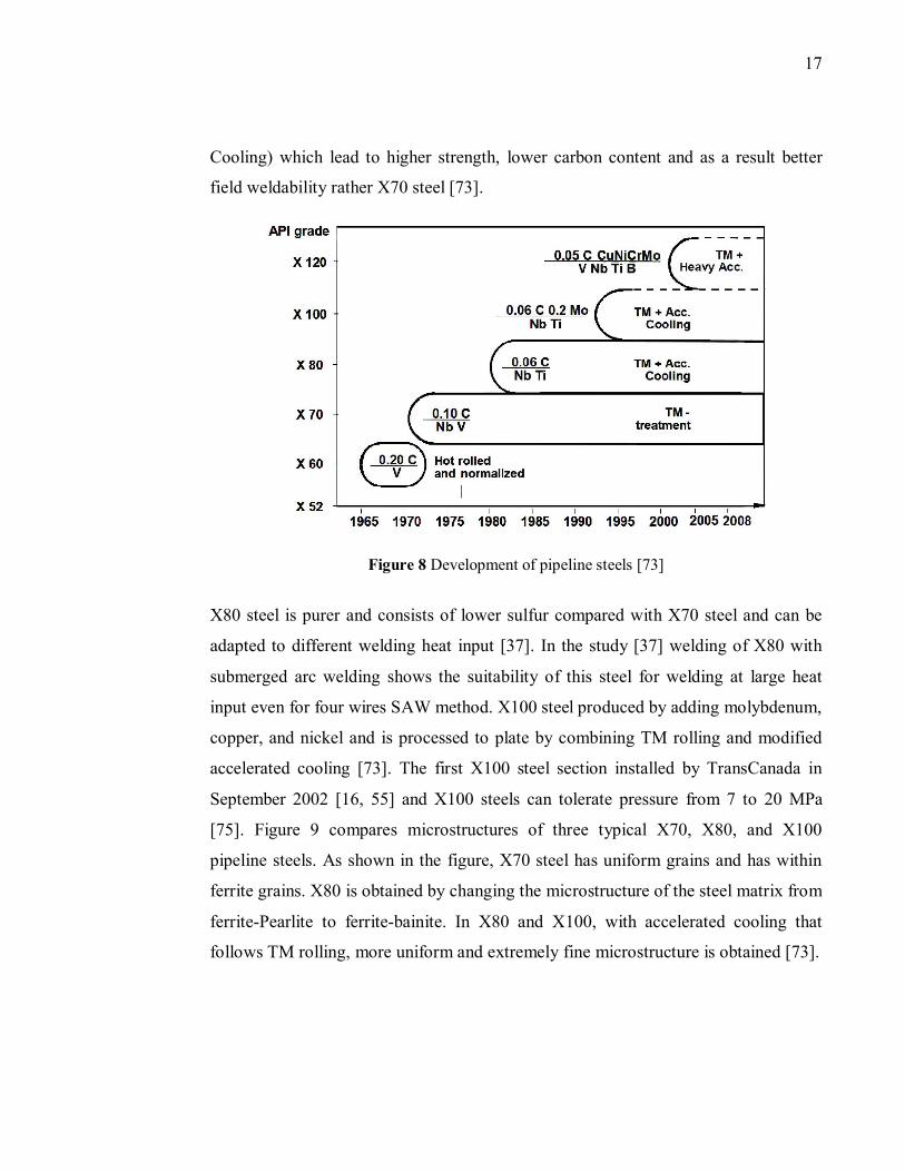
Thermo-mechanical rolling (TM treatment) method which provides possibility of
producing material from steels up to X70 was invented in the early seventies to
replace with hot rolling and normalizing method. X70 is micro-alloyed consists of
niobium and vanadium with lower amount of carbon. Figure 8 depicts the historical
development of the pipe steels [73]. X70 steel showed great welding result in China's
East-to-West gas transmission project [37]. As can be seen from the figure, X80 steel
were invented by combining TM rolling and subsequent accelerated cooling (Acc
17
Cooling) which lead to higher strength, lower carbon content and as a result better
field weldability rather X70 steel [73].
Figure 8 Development of pipeline steels [73]
X80 steel is purer and consists of lower sulfur compared with X70 steel and can be
adapted to different welding heat input [37]. In the study [37] welding of X80 with
submerged arc welding shows the suitability of this steel for welding at large heat
input even for four wires SAW method. X100 steel produced by adding molybdenum,
copper, and nickel and is processed to plate by combining TM rolling and modified
accelerated cooling [73]. The first X100 steel section installed by TransCanada in
September 2002 [16, 55] and X100 steels can tolerate pressure from 7 to 20 MPa
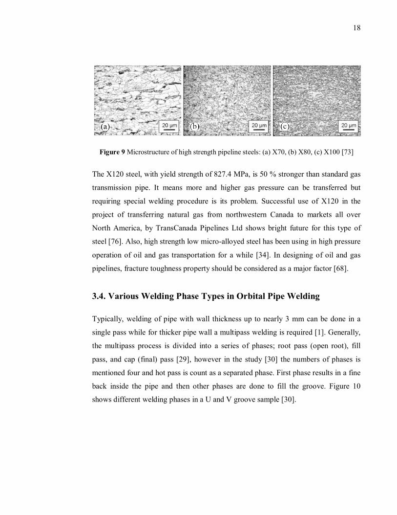
[75]. Figure 9 compares microstructures of three typical X70, X80, and X100
pipeline steels. As shown in the figure, X70 steel has uniform grains and has within
ferrite grains. X80 is obtained by changing the microstructure of the steel matrix from
ferrite-Pearlite to ferrite-bainite. In X80 and X100, with accelerated cooling that
follows TM rolling, more uniform and extremely fine microstructure is obtained [73].
18
Figure 9 Microstructure of high strength pipeline steels: (a) X70, (b) X80, (c) X100 [73]
The X120 steel, with yield strength of 827.4 MPa, is 50 % stronger than standard gas
transmission pipe. It means more and higher gas pressure can be transferred but
requiring special welding procedure is its problem. Successful use of X120 in the
project of transferring natural gas from northwestern Canada to markets all over
North America, by TransCanada Pipelines Ltd shows bright future for this type of
steel [76]. Also, high strength low micro-alloyed steel has been using in high pressure
operation of oil and gas transportation for a while [34]. In designing of oil and gas
pipelines, fracture toughness property should be considered as a major factor [68].
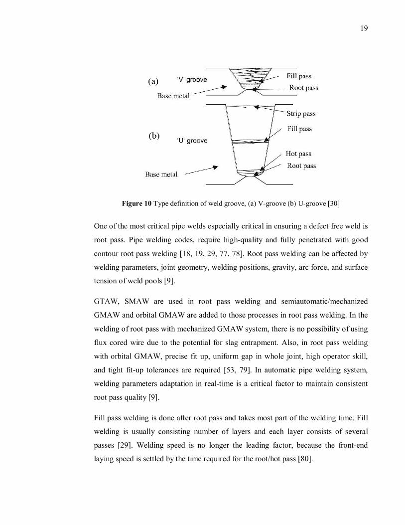
3.4. Various Welding Phase Types in Orbital Pipe Welding
Typically, welding of pipe with wall thickness up to nearly 3 mm can be done in a
single pass while for thicker pipe wall a multipass welding is required [1]. Generally,
the multipass process is divided into a series of phases; root pass (open root), fill
pass, and cap (final) pass [29], however in the study [30] the numbers of phases is
mentioned four and hot pass is count as a separated phase. First phase results in a fine
back inside the pipe and then other phases are done to fill the groove. Figure 10
shows different welding phases in a U and V groove sample [30].
19
Figure 10 Type definition of weld groove, (a) V-groove (b) U-groove [30]
One of the most critical pipe welds especially critical in ensuring a defect free weld is
root pass. Pipe welding codes, require high-quality and fully penetrated with good
contour root pass welding [18, 19, 29, 77, 78]. Root pass welding can be affected by
welding parameters, joint geometry, welding positions, gravity, arc force, and surface
tension of weld pools [9].
GTAW, SMAW are used in root pass welding and semiautomatic/mechanized
GMAW and orbital GMAW are added to those processes in root pass welding. In the
welding of root pass with mechanized GMAW system, there is no possibility of using
flux cored wire due to the potential for slag entrapment. Also, in root pass welding
with orbital GMAW, precise fit up, uniform gap in whole joint, high operator skill,
and tight fit-up tolerances are required [53, 79]. In automatic pipe welding system,
welding parameters adaptation in real-time is a critical factor to maintain consistent
root pass quality [9].
Fill pass welding is done after root pass and takes most part of the welding time. Fill
welding is usually consisting number of layers and each layer consists of several
passes [29]. Welding speed is no longer the leading factor, because the front-end
laying speed is settled by the time required for the root/hot pass [80].
20
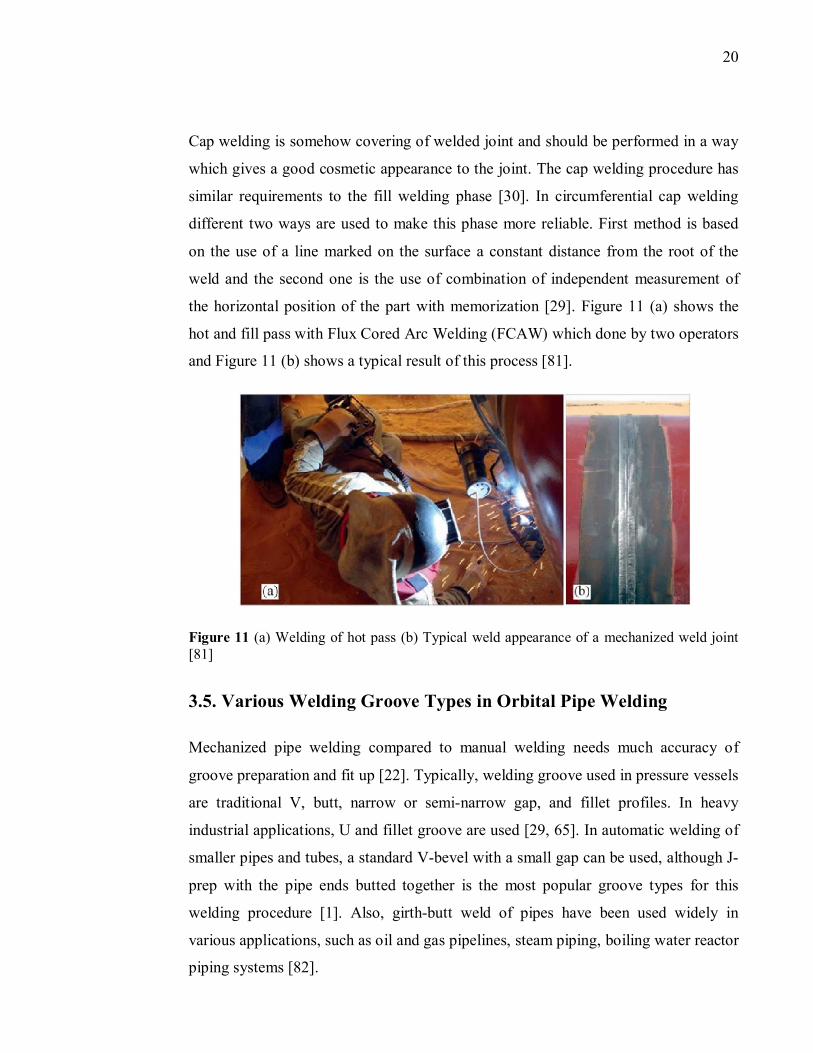
Cap welding is somehow covering of welded joint and should be performed in a way
which gives a good cosmetic appearance to the joint. The cap welding procedure has
similar requirements to the fill welding phase [30]. In circumferential cap welding
different two ways are used to make this phase more reliable. First method is based
on the use of a line marked on the surface a constant distance from the root of the
weld and the second one is the use of combination of independent measurement of
the horizontal position of the part with memorization [29]. Figure 11 (a) shows the
hot and fill pass with Flux Cored Arc Welding (FCAW) which done by two operators
and Figure 11 (b) shows a typical result of this process [81].
Figure 11 (a) Welding of hot pass (b) Typical weld appearance of a mechanized weld joint [81]
3.5. Various Welding Groove Types in Orbital Pipe Welding
Mechanized pipe welding compared to manual welding needs much accuracy of
groove preparation and fit up [22]. Typically, welding groove used in pressure vessels
are traditional V, butt, narrow or semi-narrow gap, and fillet profiles. In heavy
industrial applications, U and fillet groove are used [29, 65]. In automatic welding of
smaller pipes and tubes, a standard V-bevel with a small gap can be used, although J-
prep with the pipe ends butted together is the most popular groove types for this
welding procedure [1]. Also, girth-butt weld of pipes have been used widely in
various applications, such as oil and gas pipelines, steam piping, boiling water reactor
piping systems [82].
21
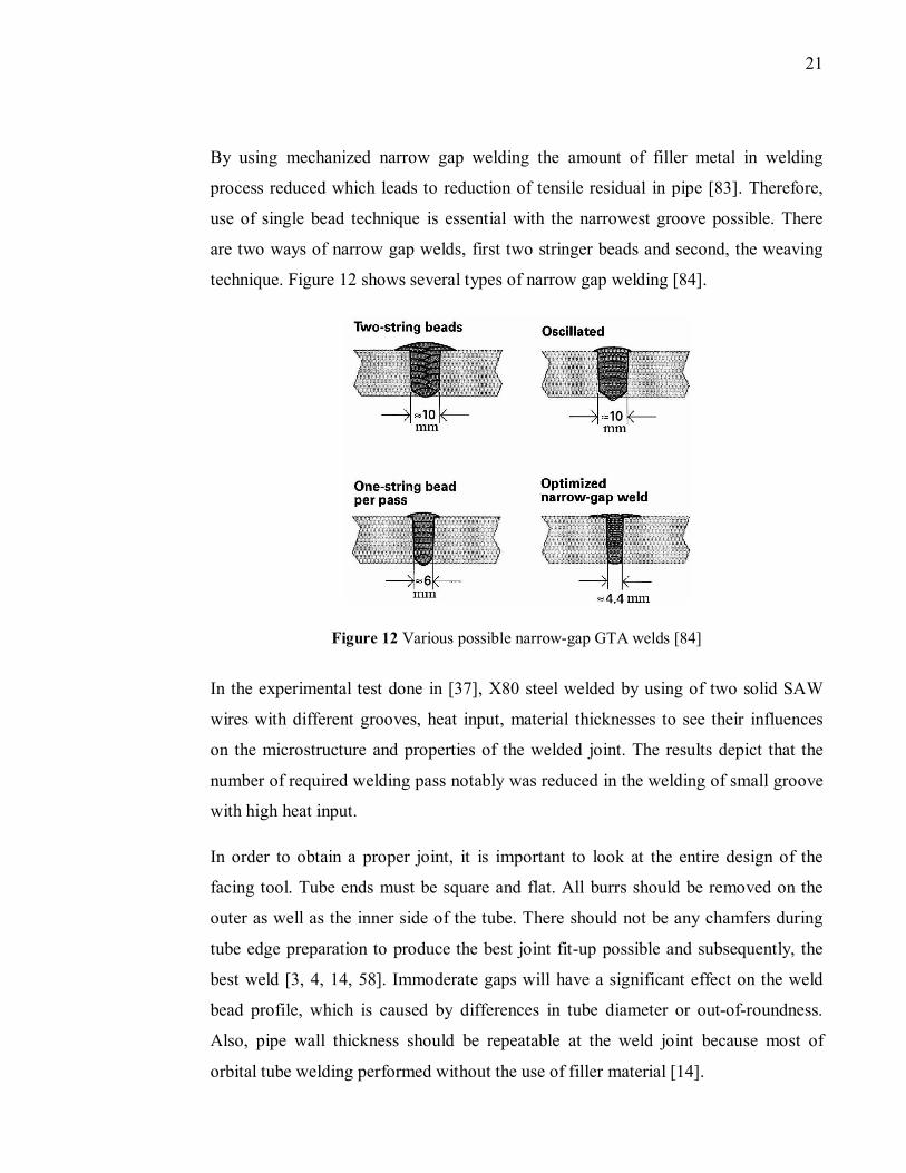
By using mechanized narrow gap welding the amount of filler metal in welding
process reduced which leads to reduction of tensile residual in pipe [83]. Therefore,
use of single bead technique is essential with the narrowest groove possible. There
are two ways of narrow gap welds, first two stringer beads and second, the weaving
technique. Figure 12 shows several types of narrow gap welding [84].
Figure 12 Various possible narrow-gap GTA welds [84]
In the experimental test done in [37], X80 steel welded by using of two solid SAW
wires with different grooves, heat input, material thicknesses to see their influences
on the microstructure and properties of the welded joint. The results depict that the
number of required welding pass notably was reduced in the welding of small groove
with high heat input.
In order to obtain a proper joint, it is important to look at the entire design of the
facing tool. Tube ends must be square and flat. All burrs should be removed on the
outer as well as the inner side of the tube. There should not be any chamfers during
tube edge preparation to produce the best joint fit-up possible and subsequently, the
best weld [3, 4, 14, 58]. Immoderate gaps will have a significant effect on the weld
bead profile, which is caused by differences in tube diameter or out-of-roundness.
Also, pipe wall thickness should be repeatable at the weld joint because most of
orbital tube welding performed without the use of filler material [14].
22
3.6. Orbital Welding Parameters and Equipment
A welding quality is good when weld have enough penetration, desired
microstructure, and right welding profile without any spatter [57]. Typically, pipe
welding equipment manufacturers suggest a series of pre-calculated weld program for
different tube wall thicknesses, diameters and materials [4].
Arc Voltage
In pipe welding, arc voltage which is directly related to the arc length depends on
weld current, stability of arc, and concentricity of pipe [3, 4]. Arc length influences
weld penetration and longer arc length leads to less penetration and too short arc
length produces poor penetration in very low arc power. The distance between
electrode and tube should be kept constant to avoid stubbing-out. In a constant arc
length, by increasing feed rate, penetration and HAZ increased [57].
Welding speed
Using of automatic orbital welding is the most effective way to control welding speed
[51]. The main goal of welding machine is to weld as fast as possible while the
quality of weld stays constant. Weld speed depends on the tube wall thickness and
flow rate of material [4, 49]. In the study [4] welding speed is suggested to be set at
1.7 to 4.2 mm/s, running faster on thinner-wall materials and slower on heavy-wall
tube.
Welding current
Welding current affects the depth of penetration by influencing heat concentration in
the weld pool [57]. The main goal in welding current controlling is to obtain defect
free welds with full penetration. During of orbital pipe welding processes, usually
multiple levels of weld current used to compensate for heat buildup in the tube.
Factors influence the welding current are, weld speed, base material, wall thickness,
and shielding gas [3].
23
Arc pulsing
In welding with arc pulsing, in a fixed duration of time the power source pulses
rapidly between a peak and background current to reduce heat input and as a result,
producing better and repeatable weld quality. This method may be used in welding of
joints with poor fit up which are difficult to weld. The main advantage of using arc
pulsing in orbital welding system is decreasing of the gravity effects on the molten
weld. During welding of pipe in the position of 6 and 12 O’clock the gravity pulls
molten materials and makes the welding process difficult. When the welding torch is
in those positions by reducing the current to its background current (lowest) the
molten materials can solidify before dropping to the ground [4].
3.6.1. Power Source
More recently, variable polarity welding power supplies have been introduced into
the pipe welding world. In the pipe construction world, portability is the key.
Developed power supplies used today in orbital pipe welding, tend to be at the top of
the range. They record automatically the majority of required welding data for
projects with a high level of microcomputer control of pulsing parameters and multi-
schedule welding parameters [46, 85].
The physical size, weight, and input voltage of the power supply are important
considerations [1]. The power supply controls the arc welding current and the power
to drive the motor in the weld head. It switches the shielding gases on and off as
necessary [4]. A power source output of 200 to 300 A generally suffices for
conventional mechanical welding. An orbital welding power source integrates the
controls that operate the various weld head functions with the power source. A
standard power source can provide output power only and cannot be used for
mechanized orbital welding. In addition, multipass welding requires multipass
programming, which usually is done with an integrated microprocessor and custom
software [1] .
24
For smooth welding, the power source must have a fast power switching device. A
fast switch operation permits quick responses to changes in arc conditions. For
example, a tight part fit-up or a narrow gap in a pipe joint forces the welder to push
the rod close to the joint, often causing a premature arc and sticking. A fast
responding power source can sense this through feedback circuits and boost amperage
before the rod has a chance to stick. An inverter allows welders to make small current
adjustments when welding to produce a smooth and stable arc and control over the
weld puddle [86].
Inverters may offer higher power efficiency and a better power factor than other
welding machines, making for lower operating costs. Control electronics allow
manipulation of static and dynamic characteristics of welding power so that a single
power unit may perform all welding processes. Inverters also link well to computers
and microprocessors. Some inverters automatically accept primary input voltage
without wiring changes or alteration to accept either 230 or 460 V, single or 3 phase,
50 or 60 Hz input. Inverters do the same work as transformer-rectifiers. A silicon
controlled rectifier “chops” the alternating current (AC) output, or turns it on and off,
and rectifies to direct current (DC) welding power at 20 kHz; inverters operate at 60
kHz, or 60,000 cycle per second [86].
One way to classifying power supplies is by how much amperage, or heat, the unit
can generate at a given duty cycle. For thin work, look for low-end amperage control
to prevent burn-through. Thick work requires enough amperage to ensure good
penetration. For example, GMAW of 18 gage steel in a single pass takes about 70 A,
where welding 12.7 mm steel in a single pass requires about 315 A.
Duty cycle is the number of minutes out of a 10 minute cycle a power supply can
operate. For example, a machine that can deliver 300 A of welding current at a 60 %
duty cycle can weld continuously at 300 A for 6 minutes, and then must cool down
for 4 minutes to prevent overheating. Duty cycle and amperage are inversely
proportional. Operating at 250 A, the same machine has a 100 % duty cycle- it can
25
weld without stopping at this amperage. Operating at 400 A, it has about a 20 % duty
cycle [86].
Analog power source
Analog power sources are programmed by entering the desired speed, amperage, and
other parameters on dials and putting the machine into motion with mechanical
switches. The units allow one pass (one orbit around the pipe) to be programmed.
When multiple passes are required, welders must stop the machine, reset the dials for
the next pass, and restart the weld. Analog power sources are easy to understand
operation, good tolerance of environmental extremes, and simple maintenance
requirements. However, analog power sources cannot lock out unauthorized changes
in critical parameters, and they do not store programs [1].
Microprocessor based power sources
Microprocessor based units require a longer learning curve than do analog power
sources. Most weld programming is done by the welder using the equipment and can
store up to 100 weld programs, so most programs use simple prompts that require
little computer literacy. These power sources have the features of, using many levels
of programming for all parameters, possibility of multi passes without stopping,
usability in automatic weld procedure, storage of weld program, simplifying the weld
development process. Also, use of solid state data cards that allow program transfer
between systems or off-line programming on personal computers [1, 46].
3.6.2. Filler Wire
Filler wire manufacturers has been involved with different challenges since
improving of pipe and welding manufacturing require new filler wire technology as
well. Flux cored wires were invented in 1957 which consists of a metal sheath
containing a core of flux [87]. The core is mixture of powdered ingredients, including
fluxing elements, deoxidizers, denitriding compounds, and alloying materials to
improve hardness, strength and as a result corrosion resistance. Two methods are
26
used to produce flux cored wire, standard and all position. In all position wire, puddle
freezed much faster than standard wire and should be used in orbital applications due
to the nature of the welding [53, 88].
Using of wires containing a small amount of titanium first was tested in 1960s in the
UK and USA on transmission pipelines. In this case, smaller grain size is obtained
and the welding result was quite acceptable at that time and burn-off rate of the wire
was reduced. Also, this type of wire increases welder’s comfort, weld toughness, and
the proportion of the arc energy available to melt the edges of the weld preparation.
Further, this wire reduces defect rate and lack of fusion which is the most serious
problem in semi-automatic pipe welding [7, 21]. In the study [7] two wires, first 0.8
mm without titanium and second 0.9 mm with titanium were used at 200 A and 25 V.
The result shows more burn-off rate for the first one, while 33 % of the available heat
was used to melt the wire; this number was 24 % in the second case.
Today, for pipe welding with mechanized system, both titanium bearing and titanium
free wires are using successfully. But, carbon manganese wires without titanium are
gaining in popularity due to the mechanized or fully automatic pipe welding users’
feedback. Productivity, even with mechanized pipe welding systems is an important
factor and manufacturers have begun using of metal cored wires instead of solid wires
in mechanized downhill welding. In 2000s, metal cored wires were used for the first
time in pipeline welding [7, 21]. Metal cored wires are a variant of flux cored wires,
but differ in that the flux consists almost entirely of metal. These types of wires have
the ability of using in welding either double up or double down due to the small
isolated islands of silicon shaped on the solidified weld bead [47].
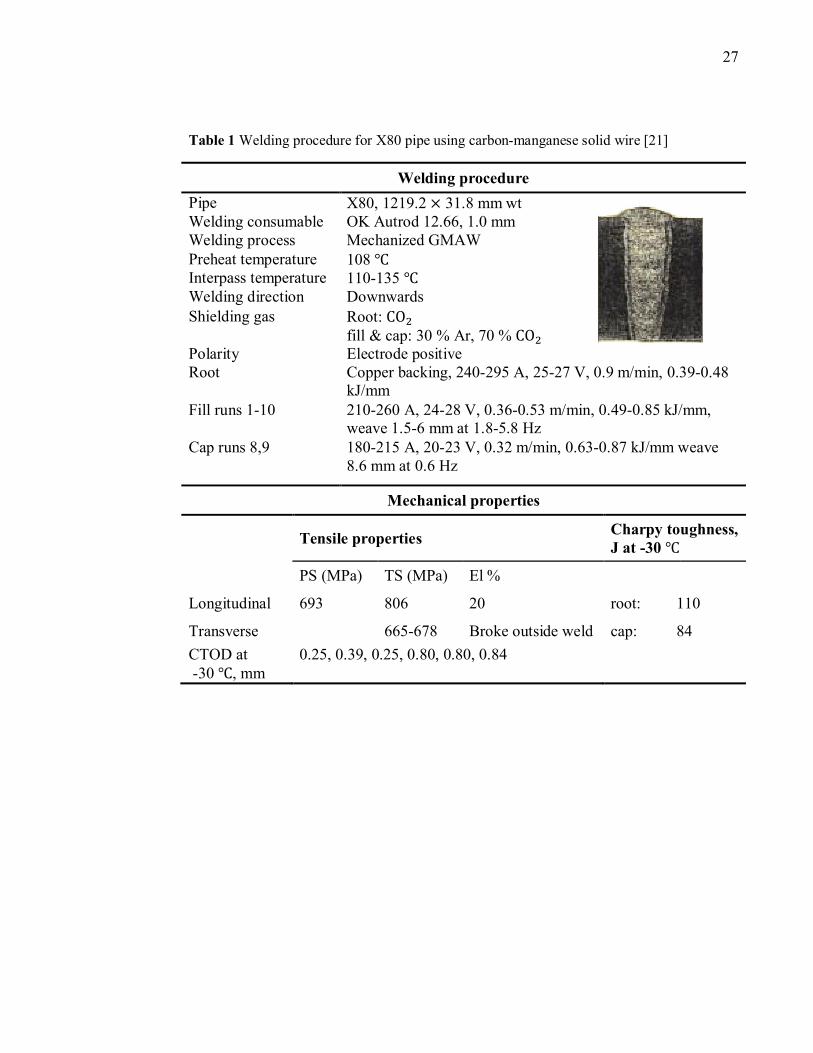
Table 1 and Table 2 illustrate procedures and mechanical properties for welding of
X80 pipe with a carbon manganese solid wire and a 0.8 % nickel metal cored wire
done in the study [21].
27
Table 1 Welding procedure for X80 pipe using carbon-manganese solid wire [21]
Welding procedure
Pipe X80, 1219.2 × 31.8 mm wt Welding consumable OK Autrod 12.66, 1.0 mm Welding process Mechanized GMAW Preheat temperature 108 ℃ Interpass temperature 110-135 ℃ Welding direction Downwards Shielding gas Root: CO�
fill & cap: 30 % Ar, 70 % CO� Polarity Electrode positive Root Copper backing, 240-295 A, 25-27 V, 0.9 m/min, 0.39-0.48
kJ/mm Fill runs 1-10 210-260 A, 24-28 V, 0.36-0.53 m/min, 0.49-0.85 kJ/mm,
weave 1.5-6 mm at 1.8-5.8 Hz Cap runs 8,9 180-215 A, 20-23 V, 0.32 m/min, 0.63-0.87 kJ/mm weave
8.6 mm at 0.6 Hz
Mechanical properties
Tensile properties
Charpy toughness, J at -30 ℃
PS (MPa) TS (MPa) El %
Longitudinal 693 806 20 root: 110
Transverse 665-678 Broke outside weld cap: 84
CTOD at -30 ℃ , mm
0.25, 0.39, 0.25, 0.80, 0.80, 0.84
28
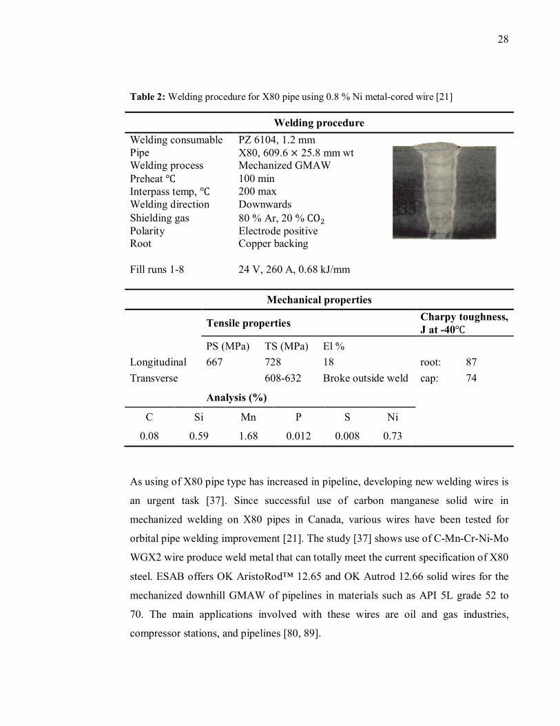
Table 2: Welding procedure for X80 pipe using 0.8 % Ni metal-cored wire [21]
Welding procedure
Welding consumable PZ 6104, 1.2 mm Pipe X80, 609.6 × 25.8 mm wt Welding process Mechanized GMAW Preheat ℃ 100 min Interpass temp, ℃ 200 max Welding direction Downwards Shielding gas 80 % Ar, 20 % CO� Polarity Electrode positive Root Copper backing
Fill runs 1-8 24 V, 260 A, 0.68 kJ/mm
Mechanical properties
Tensile properties
Charpy toughness, J at -40℃
PS (MPa) TS (MPa) El %
Longitudinal 667 728 18 root: 87
Transverse 608-632 Broke outside weld cap: 74
Analysis (%)
C Si Mn P S Ni
0.08 0.59 1.68 0.012 0.008 0.73
As using of X80 pipe type has increased in pipeline, developing new welding wires is
an urgent task [37]. Since successful use of carbon manganese solid wire in
mechanized welding on X80 pipes in Canada, various wires have been tested for
orbital pipe welding improvement [21]. The study [37] shows use of C-Mn-Cr-Ni-Mo
WGX2 wire produce weld metal that can totally meet the current specification of X80
steel. ESAB offers OK AristoRod™ 12.65 and OK Autrod 12.66 solid wires for the
mechanized downhill GMAW of pipelines in materials such as API 5L grade 52 to
70. The main applications involved with these wires are oil and gas industries,
compressor stations, and pipelines [80, 89].
29
3.6.3. Shielding Gas
Both, solid and flux cored wires required proper shielding gas to have higher
productivity. In orbital pipe welding system, equipments are mounted close to the
torch and lower amount of spatter is a factor that should be considered. Selecting of
shielding gas composition is highly depended on the wire manufacturer’s
recommendation. Arc stability, general weld ability, spatter, and metallurgy of the
deposited metal are affected by shielding gas [53]. Shielding gas prevents the molten
material from combining with oxygen in the ambient atmosphere [3].
Typically, more than one gas composition is suggested by manufacturers. CO�as a
shielding gas for pipeline fabricators has the advantages of very secure weld
penetration and less expensive. On the other hand, CO�shielding gas is not popular
due to its unfavorable globular droplet detachment and the high amount of spatter
[53, 80]. Argon is the most commonly used shielding gas in welding processes. In
semi-automatic and fully automatic welding, the use of argon based mixed gases
dominates. This mixture can be either, argon/hydrogen or helium and argon/CO�gas
mixtures because of their advantages, such as fewer spatters, higher stability of arc,
and possibility of using higher welding currents [3, 53, 80]. Argon is the most
common root gas, but for duplex stainless steel and high-alloyed austenitics,
nitrogen-based backing is recommended (e.g. 90 % N� + 10 % H�) [90].
4. Adaptive Orbital Pipe Welding
In many cases of orbital pipe welding process, tolerance of the workpiece and pipe
thickness are so precise that the weld joint can be welded without any problem while
direction of welding is straight. In some cases, especially large diameter of pipes, due
to some reasons, such as pre-machining tolerance of the workpiece, fit-up precision
and unfitness of the joint, there can be significant variations in weld joint shapes and
areas. This would result in poor welding appearance and possibly defects.
Consequently, an orbital welding system without feedback and controlling of the
welding parameters may easily result in poor welding quality, particularly, when the
30
workpiece and welding joint are not prepared in good condition and are far away
from ideal requirements [30, 91, 92].
Develop and improve intelligent technologies for orbital pipe welding, such as vision
sensing, real-time intelligent control [93, 94, 95, 96, 97, 98, 99], and scan welding
technique [100], may be an effective approach to overcome this problem. This
controlling of parameters is so called adaptive welding which has been used with
good results in industry for some time [95]. Adaptive welding systems have been
called the Holy Grail of the industry [8].
Moreover, stability and accuracy of welding parameters controlling is very important
to make sure penetration is consistent and predictable. Today’s orbital welding
systems offer computer controls that store a variety of welding parameters that can be
called up as needed. Closed loop control of the welding parameters ensures stable,
constant, and accurate values with less room for error or defects [4, 29]. Adaptive,
practically means finding the center of the joint (dynamic joint tracking) instead of
having a person always steer everything accurately. Also, in adaptive welding system,
controlling the weld power, wire feed, rotation (speed), pulse time, oscillation width,
torch motion and position, etc. are done automatically to help simplify operation and
produce a high quality weld [8, 11]. Three following basic steps counted in the study
[8] and should be implemented to have an adaptive arc welding process:
In the first step, entire of the joint observed precisely and possible defects or
deviations in the groove walls are noticed. The system performs a comprehensive
inventory of the joint to be welded. In this observation, measurements, such as
temperature of the workpiece and the uniformity of the groove are considered. The
system also keeps an inventory of previous welding passes and draws and uses it as a
knowledge base.
Second step is recipe for decision making. The automated orbital welding system
organizes the effect of the different process variables according to importance. And
finally, integrating the rest of the system is the third step. Welding control system
require coupling of power source, torch motion, and wire feeder. These three
31
parameters, in some currently used welding systems are controlled separately for
accurate control of heat. This is important especially in welding of different pieces
with various asymmetrical or non-uniform heat capacities.
Recently, significant improvements have been obtained in adaptive orbital welding
system. Different studies have done in weld pool geometry sensing, modeling and
intelligent control of the weld quality and process monitoring. But still needs of more
efforts on this topic is sensed due to the complexity of welding process, real-time and
opening limits in orbital systems [9, 99, 101, 102, 103]. Today, multi laser vision
sensors, thermal scanning, image processing, neural network model, machine vision,
or optical sensing are used in various fully automatic orbital welding system to
improve performance and reliability.
Generally, adaptive control of the welding parameters is not used in root pass welding
to guaranty weld penetration. Adaptive control of the orbital welding process must be
performed during the fill pass welding. There are two reasons for this: first,
sometimes joint area/height in on side of groove is larger than the other, therefore to
compensate this mismatch across the joint, weld parameters should be different on
each side of the joint. Secondly, sometimes in forming process of pipe especially in
pipes with large diameter, the joint volume on one side is much larger than the other.
Consequently, travel and wire feed speed, current/voltage level should be adjusted to
compensate for variations in the joint along the welding direction [29].
5. Most Used Welding Processes in Orbital Pipe Welding
Recently, high demands of automation of pipe welding process, with higher level of
productivity and accuracy propelled welding manufacturers to produce newer orbital
pipe welding systems. The choice of welding process is largely dependent on the steel
grades to be welded [55]. Generally, welding process for pipeline consists of root
pass and fills pass welding. The root pass by method of orbital GTAW is performed
by the skilled workers due to the possibility for defect welded. STT, short circuit,
modified short arc GMAW are other choices for root pass welding. Today, mainly for
32
fill pass welding of pipe mostly GMAW method is used [104]. Therefore, it is
completely necessary to be employed the automatic welding processes in order to
improve quality, productivity and job environment [104, 105]. In this study,
processes, such as GTAW (for process and pressure piping) [11], FCAW (for heavy-
wall, large-diameter pipes) [11], Hybrid Laser Arc Welding (HLAW), GMAW and
its variations (tandem, dual-tandem, double-electrode, twin wire, modified short arc,
pulsed arc, Rapid arc, and STT) which can be used in orbital pipe welding system
will be explained in details.
Also, there is possibility of using PAW in orbital pipe welding applications. This
process has the advantages of smaller heat affected area, lower air porosity, higher
aspect ratio (depth to width rate), and lower residual stress [106]. PAW compared to
the GTAW is highly constricted and this feature leads to excellent linear relationship
of arc length with the arc voltage under the same welding current [107].
Even with numerous advantages involved with PAW process, few investments have
done for this process. Recently, some studies have done in the case of using PAW for
pipe welding applications. In the study [107] the transferred arc PAW for pipe
welding is investigated. This process typically operates in either keyhole or melt-in
(conduction) mode. Usually, a common type of steel can be easily welded using
keyhole mode of plasma arc welding process due to the contracted arc between the
tungsten electrode and workpiece [108]. Keyhole mode can obtain much deeper
penetration compared with other arc welding processes. Again, in the study [107]
double-stage PAW process which is proposed to avoid problems and combine
advantages in keyhole and melt-in modes explained. Due to the limited studies that
have done in the case of orbital pipe welding with PAW process, the author would
prefer not to go in more details for this process.
33
5.1. Gas Tungsten Arc Welding (GTAW)
GTAW process is an extremely important arc welding process [103, 109]. During the
1960s, to increase penetration of automated GTAW process, current extended to
higher level. At currents above about 250A, the arc tends to displace the weld pool,
this effect increased as the current increases more. Recent development in GTAW
introduce new methods of welding, such as active fluxes (A-GTAW), dual shield
GTAW, narrow gap GTAW, keyhole GTAW and laser-GTAW hybrid processes
[110]. Today orbital GTAW is widely used for a variety of applications [111].
There are some limitations of using mechanized GTAW process, such as high heat
input, low travel speed, low deposition rate, requirement of higher operator skill
level, cost prohibitive on larger diameter pipe, requirement of machining of pipe ends
in the field, and requirement of a special J-prep bevel geometry to make the initial
root pass [77, 111, 112].
GTAW is known for its versatility and high joint quality. Generally, Orbital GTA
pipe welding procedure practice, two passes are used for an acceptable pipe weld.
Although several major welding processes can be used in root pass welding, GTAW
is probably the most common choice for welding of this phase. The second or cover
pass with filler material is used to obtain sufficient convexity on the outer side of the
pipe weld. For welding of pipes with outside diameter less than 200 mm and under
Schedule 10, enough GTAW should be done to have full penetration in wall
thickness. For welding of pipe over Schedule 10, pre-machining of joints required to
decrease the wall thickness that needs to be penetrated during the root pass. As a
result, costs of welding as well as preparation time increase in orbital GTAW of large
diameter pipes. Also, using of filler material turn into compulsory in order to produce
weld bead contour with required positive reinforcement [110, 113].
Automatic orbital GTAW system is used in the industrial welding of tubes and ducts
of diverse sized diameters and thicknesses. This process is used in situations where
maximum leak integrity, high performance, or ultra cleanliness is of paramount
34
importance. The minimal heat input permits distortion control and the retaining of
dimensional accuracy [2, 48]. This process can be used in various industries, such as
steam generation components for fossil power plants, process piping for chemical
plants, and automotive exhaust gas system [111, 114].
It is widely accepted that orbital GTAW is the most suitable process for welding
stainless steel tubes and can be used with a wide variety of materials, including
highly reactive or refractory metals [4, 51, 110]. The mechanical, thermal, stability,
and corrosion resistance requirements of the application dictate the material chosen. It
is commonly used for welding difficult to weld metals such as aluminum pipe,
magnesium, copper, titanium and many other nonferrous metals [4, 9, 45, 115, 116].
By using orbital GTAW at the Angra II Nuclear Power Plant in Brazil [24] the
defects of using SMAW on type 347 stainless steel, such as micro-cracking
eliminated. The orbital welds had a flatter, more uniform crown and required very
little grinding due to better and uniform control of heat input.
Recently, orbital GTAW of narrow gap is an adapted process. Figure 13 demonstrates
three different welding procedures on austenite steel pipe with thickness of 12 mm
[100]. By narrowing the cross section of the joint, depending on the wall thickness,
the joint volume is reduced by a factor of 2-3. By reducing the heat input and
increasing the welding speed as well as reducing the gap width, axial shrinkage can
be reduced to less than half of normal narrow-gap weld shrinkage. In the study [100]
mechanized orbital GTAW were used in welding of austenitic steel pipes with
different diameters to compare axial shrinkage results with conventional welding in
various weld types (Figure 13).
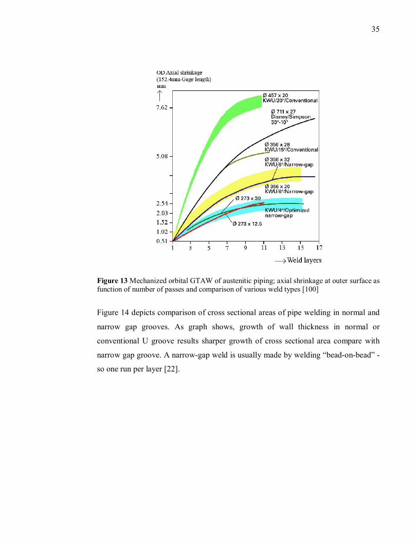
35
Figure 13 Mechanized orbital GTAW of austenitic piping; axial shrinkage at outer surface as function of number of passes and comparison of various weld types [100]
Figure 14 depicts comparison of cross sectional areas of pipe welding in normal and
narrow gap grooves. As graph shows, growth of wall thickness in normal or
conventional U groove results sharper growth of cross sectional area compare with
narrow gap groove. A narrow-gap weld is usually made by welding “bead-on-bead” -
so one run per layer [22].
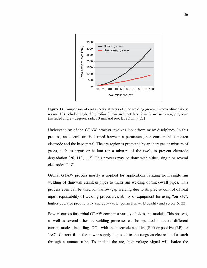
36
Figure 14 Comparison of cross sectional areas of pipe welding groove. Groove dimensions:
normal U (included angle ��°, radius 3 mm and root face 2 mm) and narrow-gap groove (included angle 4 degrees, radius 3 mm and root face 2 mm) [22]
Understanding of the GTAW process involves input from many disciplines. In this
process, an electric arc is formed between a permanent, non-consumable tungsten
electrode and the base metal. The arc region is protected by an inert gas or mixture of
gases, such as argon or helium (or a mixture of the two), to prevent electrode
degradation [26, 110, 117]. This process may be done with either, single or several
electrodes [118].
Orbital GTAW process mostly is applied for applications ranging from single run
welding of thin-wall stainless pipes to multi run welding of thick-wall pipes. This
process even can be used for narrow-gap welding due to its precise control of heat
input, repeatability of welding procedures, ability of equipment for using “on site”,
higher operator productivity and duty cycle, consistent weld quality and so on [5, 22].
Power sources for orbital GTAW come in a variety of sizes and models. This process,
as well as several other arc welding processes can be operated in several different
current modes, including ‘DC’, with the electrode negative (EN) or positive (EP), or
‘AC’. Current from the power supply is passed to the tungsten electrode of a torch
through a contact tube. To initiate the arc, high-voltage signal will ionize the
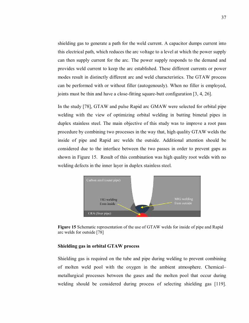
37
shielding gas to generate a path for the weld current. A capacitor dumps current into
this electrical path, which reduces the arc voltage to a level at which the power supply
can then supply current for the arc. The power supply responds to the demand and
provides weld current to keep the arc established. These different currents or power
modes result in distinctly different arc and weld characteristics. The GTAW process
can be performed with or without filler (autogenously). When no filler is employed,
joints must be thin and have a close-fitting square-butt configuration [3, 4, 26].
In the study [78], GTAW and pulse Rapid arc GMAW were selected for orbital pipe
welding with the view of optimizing orbital welding in butting bimetal pipes in
duplex stainless steel. The main objective of this study was to improve a root pass
procedure by combining two processes in the way that, high quality GTAW welds the
inside of pipe and Rapid arc welds the outside. Additional attention should be
considered due to the interface between the two passes in order to prevent gaps as
shown in Figure 15. Result of this combination was high quality root welds with no
welding defects in the inner layer in duplex stainless steel.
Figure 15 Schematic representation of the use of GTAW welds for inside of pipe and Rapid arc welds for outside [78]
Shielding gas in orbital GTAW process
Shielding gas is required on the tube and pipe during welding to prevent combining
of molten weld pool with the oxygen in the ambient atmosphere. Chemical–
metallurgical processes between the gases and the molten pool that occur during
welding should be considered during process of selecting shielding gas [119].
38
Composition of a shielding mixture in arc welding depends mostly on the kind of
material to be welded [120].
Density of shielding gas plays an important role on the efficiency of protecting the
arc and molten weld pool. Argon and CO� are the densest shielding gas, therefore
they widely use in welding industries. Argon is the most commonly used shield gas in
GTAW process. In welding of stainless steels, nickel copper and nickel based alloys
mixture of argon/helium typically used. Mixtures of 95/5 % argon/hydrogen are
incompatible with carbon steels and some exotic alloys and can cause hydrogen
embrittlement in the weld. Also, it is not recommended to use hydrogen for welding
of other materials because of possibility of producing cracks in the welds [116].
Additional hydrogen into shielding gas allows higher welding speed. Also, it
increases the volume of molten material in the weld pool due to the higher thermal
conductivity of argon–hydrogen mixtures at temperatures at which molecules of
hydrogen dissociate [121]. In most researches, the amount of hydrogen in argon is
recommended in the range of 0.5-5 % [119]. Typically, helium is used for welding on
copper materials [4] and aluminum.
Tungsten Electrodes in Orbital GTAW
This selection influences weld penetration, clean arc start, and arc wander. In orbital
GTAW systems, the most typical used electrode materials are 2 % thoriated tungsten
(contain thorium) and 2 % ceriated tungsten (contain a minimum of 97.30 % tungsten
and 1.80 to 2.20 % cerium and are referred to as 2 % ceriated). Electrode tip
geometry, such as electrode taper and tip diameter are very important in result of
weld quality. Table 3 shows characteristics of both, sharp and blunt tapers as well as
small and large tip diameter on weld result [4]. Figure 16 depicts effects of various
tapers on the size of weld bead, their rate of penetration, the arc shape, and resultant
weld profile [4].
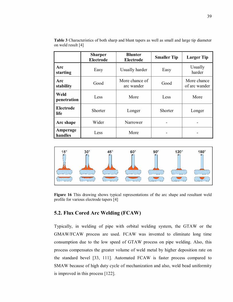
39
Table 3 Characteristics of both sharp and blunt tapers as well as small and large tip diameter on weld result [4]
Sharper
Electrode Blunter
Electrode Smaller Tip Larger Tip
Arc starting
Easy Usually harder Easy Usually harder
Arc stability
Good More chance of
arc wander Good
More chance of arc wander
Weld penetration
Less More Less More
Electrode life
Shorter Longer Shorter Longer
Arc shape Wider Narrower - -
Amperage handles
Less More - -
Figure 16 This drawing shows typical representations of the arc shape and resultant weld profile for various electrode tapers [4]
5.2. Flux Cored Arc Welding (FCAW)
Typically, in welding of pipe with orbital welding system, the GTAW or the
GMAW/FCAW process are used. FCAW was invented to eliminate long time
consumption due to the low speed of GTAW process on pipe welding. Also, this
process compensates the greater volume of weld metal by higher deposition rate on
the standard bevel [33, 111]. Automated FCAW is faster process compared to
SMAW because of high duty cycle of mechanization and also, weld bead uniformity
is improved in this process [122].
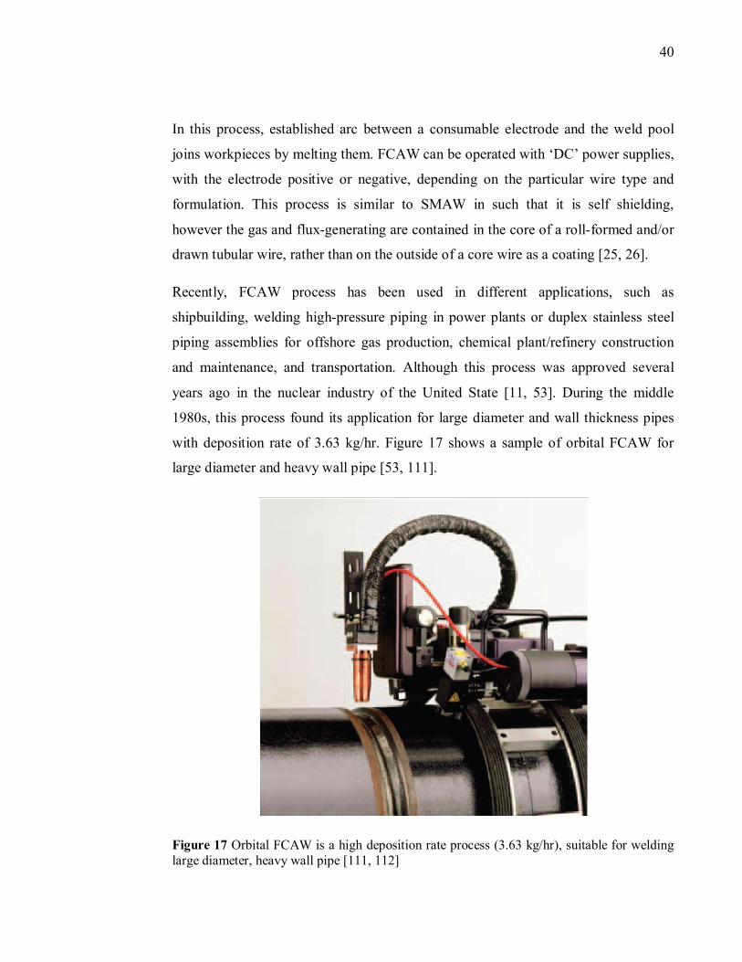
40
In this process, established arc between a consumable electrode and the weld pool
joins workpieces by melting them. FCAW can be operated with ‘DC’ power supplies,
with the electrode positive or negative, depending on the particular wire type and
formulation. This process is similar to SMAW in such that it is self shielding,
however the gas and flux-generating are contained in the core of a roll-formed and/or
drawn tubular wire, rather than on the outside of a core wire as a coating [25, 26].
Recently, FCAW process has been used in different applications, such as
shipbuilding, welding high-pressure piping in power plants or duplex stainless steel
piping assemblies for offshore gas production, chemical plant/refinery construction
and maintenance, and transportation. Although this process was approved several
years ago in the nuclear industry of the United State [11, 53]. During the middle
1980s, this process found its application for large diameter and wall thickness pipes
with deposition rate of 3.63 kg/hr. Figure 17 shows a sample of orbital FCAW for
large diameter and heavy wall pipe [53, 111].
Figure 17 Orbital FCAW is a high deposition rate process (3.63 kg/hr), suitable for welding large diameter, heavy wall pipe [111, 112]
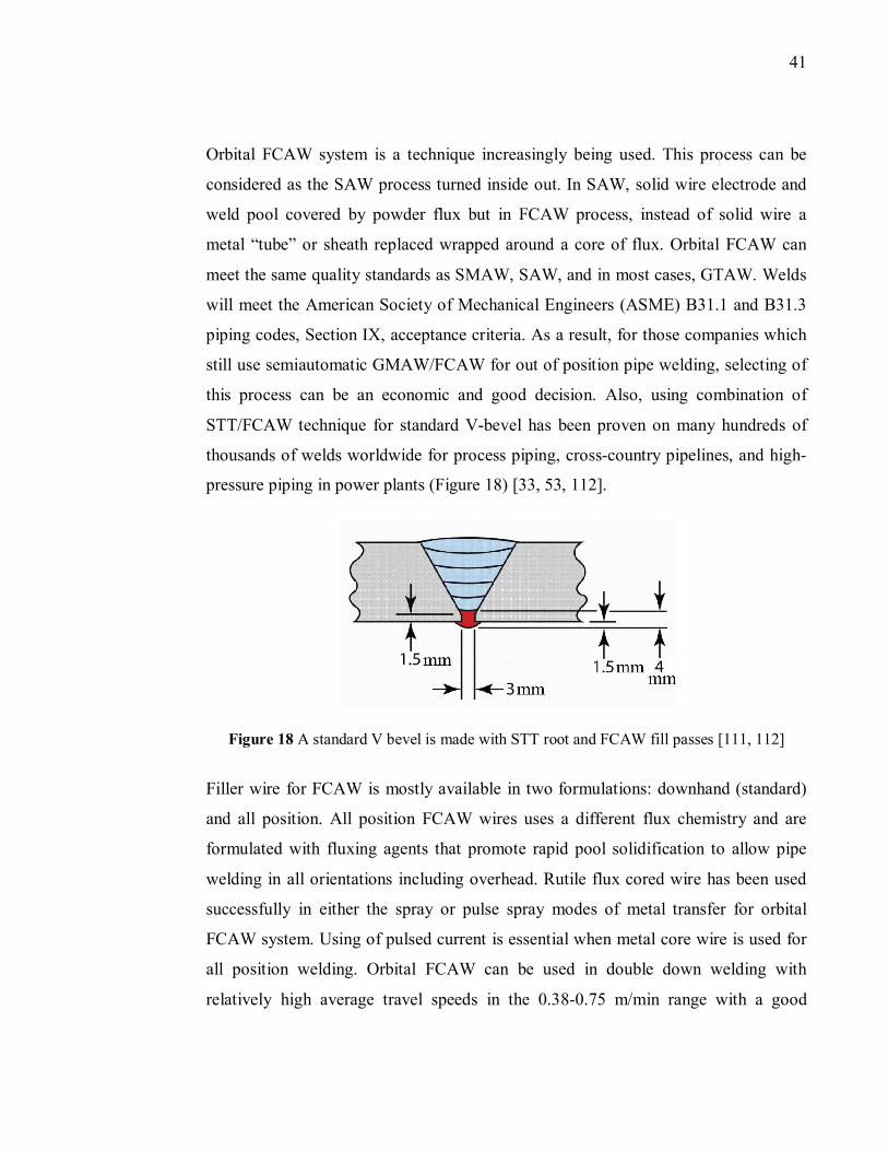
41
Orbital FCAW system is a technique increasingly being used. This process can be
considered as the SAW process turned inside out. In SAW, solid wire electrode and
weld pool covered by powder flux but in FCAW process, instead of solid wire a
metal “tube” or sheath replaced wrapped around a core of flux. Orbital FCAW can
meet the same quality standards as SMAW, SAW, and in most cases, GTAW. Welds
will meet the American Society of Mechanical Engineers (ASME) B31.1 and B31.3
piping codes, Section IX, acceptance criteria. As a result, for those companies which
still use semiautomatic GMAW/FCAW for out of position pipe welding, selecting of
this process can be an economic and good decision. Also, using combination of
STT/FCAW technique for standard V-bevel has been proven on many hundreds of
thousands of welds worldwide for process piping, cross-country pipelines, and high-
pressure piping in power plants (Figure 18) [33, 53, 112].
Figure 18 A standard V bevel is made with STT root and FCAW fill passes [111, 112]
Filler wire for FCAW is mostly available in two formulations: downhand (standard)
and all position. All position FCAW wires uses a different flux chemistry and are
formulated with fluxing agents that promote rapid pool solidification to allow pipe
welding in all orientations including overhead. Rutile flux cored wire has been used
successfully in either the spray or pulse spray modes of metal transfer for orbital
FCAW system. Using of pulsed current is essential when metal core wire is used for
all position welding. Orbital FCAW can be used in double down welding with
relatively high average travel speeds in the 0.38-0.75 m/min range with a good
42
machined and proper groove. Also, using of narrow groove bevel geometry helps in
better control of weld pool at this high travel speed of welding [47, 81].
In selecting of shielding gas for FCAW process, parameters more than cost of the gas
should be considered [123]. In FCAW steel electrodes process, CO�is certainly the
most widely used shielding gas because CO� leads higher welding speeds, good weld
penetration and lower welding cost. CO�is a comparatively inactive gas at room
temperature but in the welding arc which temperature is very high, part of the
CO�separated to form COwhich is more stable. CO�can then further decompose into
carbon (C) and oxygen (O�) [88, 123].
5.3. Gas Metal Arc Welding (GMAW)
GMAW is one of the most used processes for metals joining in industry, both in
manual and mechanized welding. This process was introduced to increase
productivity and guarantee the desirable welding quality and integrity [78, 124]. By
using an inert shielding gas, GMAW process can be as clean as GTAW with
superiority of higher deposition rate which causes higher welding speed of thicker
materials. Welding is possible by middle skill welders, although large size of torch
makes welding of corners and small area difficult [25, 77, 125].
The GMAW is widely used in fabrication process in industries due to its inherent
advantages. These advantages can be named as, high metal deposition rate, deep
penetration, smooth bead, low spatter and ease of automation with better weld quality
at permissible cost than other welding processes [57, 125]. One of the main
advantages of this process is that, the mode of molten metal transfer from the
consumable wire electrode can be intentionally changed and controlled through a
combination of shielding gas composition, power source type, electrode type and
form, arc current and voltage, and wire feed rate. There are three main types of metal
transfer (welding arc) used in GMAW process which are: short circuiting, globular,
and spray. New technologies from various companies lead to development of
43
different types of GMAW in welding industry which will be explained later in this
study [26].
The wire is fed to the arc by an automatic wire feeder, of which depending on the
wire composition, diameter, and welding application, both push and pull types are
employed. The arc is shielded from contaminants in the atmosphere by the shielding
gas such asCO�, argon, helium, etc. and this is why this process mostly in Europe is
known as Metal Inert Gas (MIG) or Metal Active Gas (MAG) welding [25, 126]. In
welding process which carbon dioxide CO� uses as shielding gas, GMAW is more
proper name for this process [26, 27].
Normally, conventional GMAW uses Constant Voltage (CV) and ‘DC’ welding
power supply. Either Direct Current Electrode Negative (DCEN) or Direct Current
Electrode Positive (DCEP) may be used, depending on the particular wire and desired
mode of molten metal transfer. But the ‘DCEP’ mode, in which the wire is connected
to the positive terminal of the power source and the power source operates in the
‘CV’ mode, is far more common. The reverse polarity contributes to a stable arc,
uniform metal transfer, and greater penetration. A ‘CV’ power source can adjust the
welding current such that the wire melting rate is equal to the given wire feed speed,
and the welding voltage, or arc length, is maintained constant [26, 124].
The main variables in all GMAW processes are, welding current, arc voltage, and
welding travel speed. Other parameters, such as welding torch angle, workpiece to
nozzle gap, welding direction, shielding gas flow rate and its pressure are auxiliary
adjustable. Typically, there are some factors kept constant during welding, such as
type of electrode and its diameter, polarity and its extension, workpiece compositions,
shielding gas, and so on [127]. The arc energy, an indicator of heat content of the
weld pool, is affected by the primary process parameters as per equation 1 [57].
E =UI
v (1)
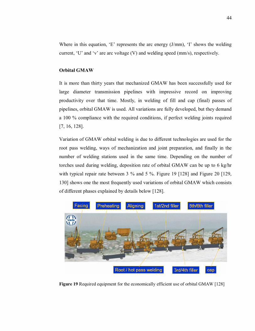
44
Where in this equation, ‘E’ represents the arc energy (J/mm), ‘I’ shows the welding
current, ‘U’ and ‘v’ are arc voltage (V) and welding speed (mm/s), respectively.
Orbital GMAW
It is more than thirty years that mechanized GMAW has been successfully used for
large diameter transmission pipelines with impressive record on improving
productivity over that time. Mostly, in welding of fill and cap (final) passes of
pipelines, orbital GMAW is used. All variations are fully developed, but they demand
a 100 % compliance with the required conditions, if perfect welding joints required
[7, 16, 128].
Variation of GMAW orbital welding is due to different technologies are used for the
root pass welding, ways of mechanization and joint preparation, and finally in the
number of welding stations used in the same time. Depending on the number of
torches used during welding, deposition rate of orbital GMAW can be up to 6 kg/hr
with typical repair rate between 3 % and 5 %. Figure 19 [128] and Figure 20 [129,
130] shows one the most frequently used variations of orbital GMAW which consists
of different phases explained by details below [128].
Figure 19 Required equipment for the economically efficient use of orbital GMAW [128]
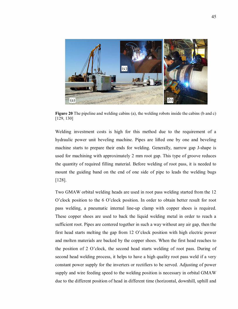
45
Figure 20 The pipeline and welding cabins (a), the welding robots inside the cabins (b and c) [129, 130]
Welding investment costs is high for this method due to the requirement of a
hydraulic power unit beveling machine. Pipes are lifted one by one and beveling
machine starts to prepare their ends for welding. Generally, narrow gap J-shape is
used for machining with approximately 2 mm root gap. This type of groove reduces
the quantity of required filling material. Before welding of root pass, it is needed to
mount the guiding band on the end of one side of pipe to leads the welding bugs
[128].
Two GMAW orbital welding heads are used in root pass welding started from the 12
O’clock position to the 6 O’clock position. In order to obtain better result for root
pass welding, a pneumatic internal line-up clamp with copper shoes is required.
These copper shoes are used to back the liquid welding metal in order to reach a
sufficient root. Pipes are centered together in such a way without any air gap, then the
first head starts melting the gap from 12 O’clock position with high electric power
and molten materials are backed by the copper shoes. When the first head reaches to
the position of 2 O’clock, the second head starts welding of root pass. During of
second head welding process, it helps to have a high quality root pass weld if a very
constant power supply for the inverters or rectifiers to be served. Adjusting of power
supply and wire feeding speed to the welding position is necessary in orbital GMAW
due to the different position of head in different time (horizontal, downhill, uphill and
46
overhead). In the new orbital welding systems, mostly it is done automatically,
however semi-automatically and manually is also possible. Two welding heads with
same parameters are selected for welding of hot and fill pass which is done downhill.
The number of working stations is depended on the wall thickness of the pipe to be
welded [128].
Mostly, in GMAW of carbon steel various mixtures of argon/CO� are used as
shielding gas. The most typical mixtures are 75 % argon/25 % CO� and 90 %
argon/10 % CO�. Different factors, such as gas, labor, wire, and energy should be
considered in the selecting process of shielding gas. Recently, the traditional mixture
of argon/CO� is replaced with mixture of argon/O�. This mixture has the advantages
of saving cost, higher welding speed, higher deposition rate, lower spatter and fumes,
usage of single tank system, spray arc at lower welding parameters, and excellent
result of weld bead and mechanical properties [131].
GMAW Variations
Significant efforts have been made to improve the welding productivity and quality in
GMAW process. These efforts can be listed as:
Auxiliary preheating of solid filler wire [132]
Multi-pass welding [133]
Preheating of welding plate [134]
Weld post-heating [135]
An ultra-narrow gap GMAW [136]
Optimization of shielding gas composition [57]
Development of new waveforms and more efficient power sources [78]
Unconventional welding process setting parameters control [57]
These mentioned methods have led to the development of many variants of GMAW
process, such as T.I.M.E [137, 138], Rapid arc, STT, tandem GMAW [78], dual-torch
and twin-wire GMAW [25], narrow-groove tandem gas metal arc welding (NG-
TGMAW) [12], modified short circuit GMAW [104], and pulsed GMAW [104].
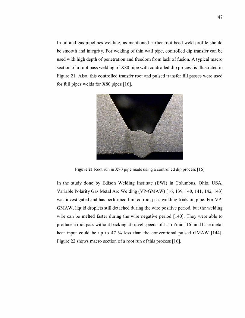
47
In oil and gas pipelines welding, as mentioned earlier root bead weld profile should
be smooth and integrity. For welding of thin wall pipe, controlled dip transfer can be
used with high depth of penetration and freedom from lack of fusion. A typical macro
section of a root pass welding of X80 pipe with controlled dip process is illustrated in
Figure 21. Also, this controlled transfer root and pulsed transfer fill passes were used
for full pipes welds for X80 pipes [16].
Figure 21 Root run in X80 pipe made using a controlled dip process [16]
In the study done by Edison Welding Institute (EWI) in Columbus, Ohio, USA,
Variable Polarity Gas Metal Arc Welding (VP-GMAW) [16, 139, 140, 141, 142, 143]
was investigated and has performed limited root pass welding trials on pipe. For VP-
GMAW, liquid droplets still detached during the wire positive period, but the welding
wire can be melted faster during the wire negative period [140]. They were able to
produce a root pass without backing at travel speeds of 1.5 m/min [16] and base metal
heat input could be up to 47 % less than the conventional pulsed GMAW [144].
Figure 22 shows macro section of a root run of this process [16].
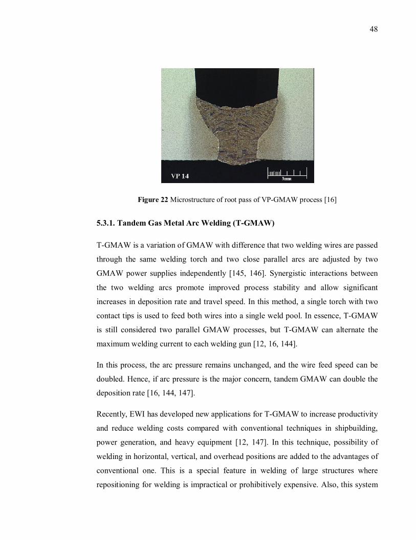
48
Figure 22 Microstructure of root pass of VP-GMAW process [16]
5.3.1. Tandem Gas Metal Arc Welding (T-GMAW)
T-GMAW is a variation of GMAW with difference that two welding wires are passed
through the same welding torch and two close parallel arcs are adjusted by two
GMAW power supplies independently [145, 146]. Synergistic interactions between
the two welding arcs promote improved process stability and allow significant
increases in deposition rate and travel speed. In this method, a single torch with two
contact tips is used to feed both wires into a single weld pool. In essence, T-GMAW
is still considered two parallel GMAW processes, but T-GMAW can alternate the
maximum welding current to each welding gun [12, 16, 144].
In this process, the arc pressure remains unchanged, and the wire feed speed can be
doubled. Hence, if arc pressure is the major concern, tandem GMAW can double the
deposition rate [16, 144, 147].
Recently, EWI has developed new applications for T-GMAW to increase productivity
and reduce welding costs compared with conventional techniques in shipbuilding,
power generation, and heavy equipment [12, 147]. In this technique, possibility of
welding in horizontal, vertical, and overhead positions are added to the advantages of
conventional one. This is a special feature in welding of large structures where
repositioning for welding is impractical or prohibitively expensive. Also, this system
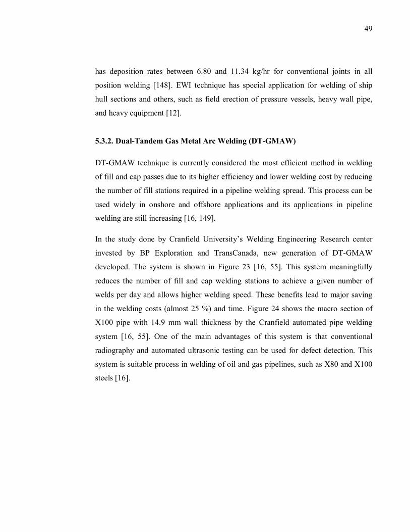
49
has deposition rates between 6.80 and 11.34 kg/hr for conventional joints in all
position welding [148]. EWI technique has special application for welding of ship
hull sections and others, such as field erection of pressure vessels, heavy wall pipe,
and heavy equipment [12].
5.3.2. Dual-Tandem Gas Metal Arc Welding (DT-GMAW)
DT-GMAW technique is currently considered the most efficient method in welding
of fill and cap passes due to its higher efficiency and lower welding cost by reducing
the number of fill stations required in a pipeline welding spread. This process can be
used widely in onshore and offshore applications and its applications in pipeline
welding are still increasing [16, 149].
In the study done by Cranfield University’s Welding Engineering Research center
invested by BP Exploration and TransCanada, new generation of DT-GMAW
developed. The system is shown in Figure 23 [16, 55]. This system meaningfully
reduces the number of fill and cap welding stations to achieve a given number of
welds per day and allows higher welding speed. These benefits lead to major saving
in the welding costs (almost 25 %) and time. Figure 24 shows the macro section of
X100 pipe with 14.9 mm wall thickness by the Cranfield automated pipe welding
system [16, 55]. One of the main advantages of this system is that conventional
radiography and automated ultrasonic testing can be used for defect detection. This
system is suitable process in welding of oil and gas pipelines, such as X80 and X100
steels [16].
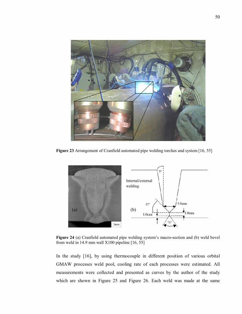
50
Figure 23 Arrangement of Cranfield automated pipe welding torches and system [16, 55]
Figure 24 (a) Cranfield automated pipe welding system’s macro-section and (b) weld bevel from weld in 14.9 mm wall X100 pipeline [16, 55]
In the study [16], by using thermocouple in different position of various orbital
GMAW processes weld pool, cooling rate of each processes were estimated. All
measurements were collected and presented as curves by the author of the study
which are shown in Figure 25 and Figure 26. Each weld was made at the same
Internal/external
welding
(b) (a)
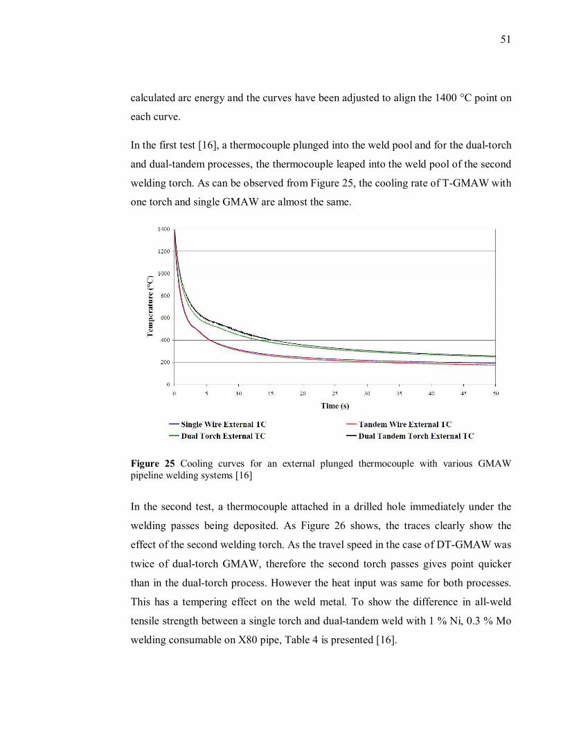
51
calculated arc energy and the curves have been adjusted to align the 1400 °C point on
each curve.
In the first test [16], a thermocouple plunged into the weld pool and for the dual-torch
and dual-tandem processes, the thermocouple leaped into the weld pool of the second
welding torch. As can be observed from Figure 25, the cooling rate of T-GMAW with
one torch and single GMAW are almost the same.
Figure 25 Cooling curves for an external plunged thermocouple with various GMAW pipeline welding systems [16]
In the second test, a thermocouple attached in a drilled hole immediately under the
welding passes being deposited. As Figure 26 shows, the traces clearly show the
effect of the second welding torch. As the travel speed in the case of DT-GMAW was
twice of dual-torch GMAW, therefore the second torch passes gives point quicker
than in the dual-torch process. However the heat input was same for both processes.
This has a tempering effect on the weld metal. To show the difference in all-weld
tensile strength between a single torch and dual-tandem weld with 1 % Ni, 0.3 % Mo
welding consumable on X80 pipe, Table 4 is presented [16].
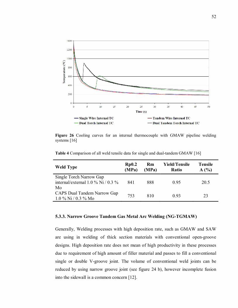
52
Figure 26 Cooling curves for an internal thermocouple with GMAW pipeline welding systems [16]
Table 4 Comparison of all weld tensile data for single and dual-tandem GMAW [16]
Weld Type Rp0.2 (MPa)
Rm (MPa)
Yield/Tensile Ratio
Tensile A (%)
Single Torch Narrow Gap internal/external 1.0 % Ni / 0.3 % Mo
841 888 0.95 20.5
CAPS Dual Tandem Narrow Gap 1.0 % Ni / 0.3 % Mo
753 810 0.93 23
5.3.3. Narrow Groove Tandem Gas Metal Arc Welding (NG-TGMAW)
Generally, Welding processes with high deposition rate, such as GMAW and SAW
are using in welding of thick section materials with conventional open-groove
designs. High deposition rate does not mean of high productivity in these processes
due to requirement of high amount of filler material and passes to fill a conventional
single or double V-groove joint. The volume of conventional weld joints can be
reduced by using narrow groove joint (see figure 24 b), however incomplete fusion
into the sidewall is a common concern [12].
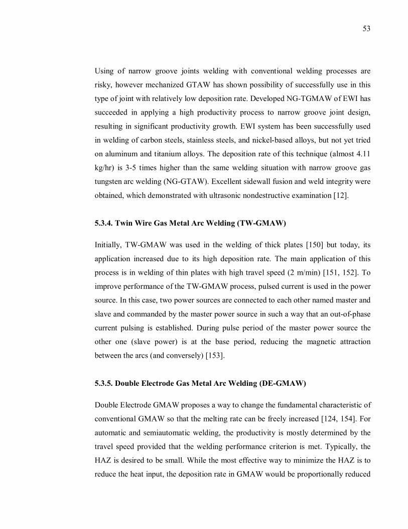
53
Using of narrow groove joints welding with conventional welding processes are
risky, however mechanized GTAW has shown possibility of successfully use in this
type of joint with relatively low deposition rate. Developed NG-TGMAW of EWI has
succeeded in applying a high productivity process to narrow groove joint design,
resulting in significant productivity growth. EWI system has been successfully used
in welding of carbon steels, stainless steels, and nickel-based alloys, but not yet tried
on aluminum and titanium alloys. The deposition rate of this technique (almost 4.11
kg/hr) is 3-5 times higher than the same welding situation with narrow groove gas
tungsten arc welding (NG-GTAW). Excellent sidewall fusion and weld integrity were
obtained, which demonstrated with ultrasonic nondestructive examination [12].
5.3.4. Twin Wire Gas Metal Arc Welding (TW-GMAW)
Initially, TW-GMAW was used in the welding of thick plates [150] but today, its
application increased due to its high deposition rate. The main application of this
process is in welding of thin plates with high travel speed (2 m/min) [151, 152]. To
improve performance of the TW-GMAW process, pulsed current is used in the power
source. In this case, two power sources are connected to each other named master and
slave and commanded by the master power source in such a way that an out-of-phase
current pulsing is established. During pulse period of the master power source the
other one (slave power) is at the base period, reducing the magnetic attraction
between the arcs (and conversely) [153].
5.3.5. Double Electrode Gas Metal Arc Welding (DE-GMAW)
Double Electrode GMAW proposes a way to change the fundamental characteristic of
conventional GMAW so that the melting rate can be freely increased [124, 154]. For
automatic and semiautomatic welding, the productivity is mostly determined by the
travel speed provided that the welding performance criterion is met. Typically, the
HAZ is desired to be small. While the most effective way to minimize the HAZ is to
reduce the heat input, the deposition rate in GMAW would be proportionally reduced
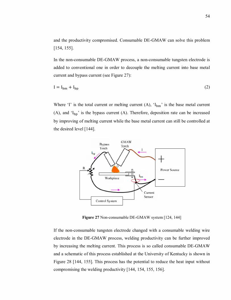
54
and the productivity compromised. Consumable DE-GMAW can solve this problem
[154, 155].
In the non-consumable DE-GMAW process, a non-consumable tungsten electrode is
added to conventional one in order to decouple the melting current into base metal
current and bypass current (see Figure 27):
I= I�� + I�� (2)
Where ‘I’ is the total current or melting current (A), ‘I�� ’ is the base metal current
(A), and ‘I��’ is the bypass current (A). Therefore, deposition rate can be increased
by improving of melting current while the base metal current can still be controlled at
the desired level [144].
Figure 27 Non-consumable DE-GMAW system [124, 144]
If the non-consumable tungsten electrode changed with a consumable welding wire
electrode in the DE-GMAW process, welding productivity can be further improved
by increasing the melting current. This process is so called consumable DE-GMAW
and a schematic of this process established at the University of Kentucky is shown in
Figure 28 [144, 155]. This process has the potential to reduce the heat input without
compromising the welding productivity [144, 154, 155, 156].
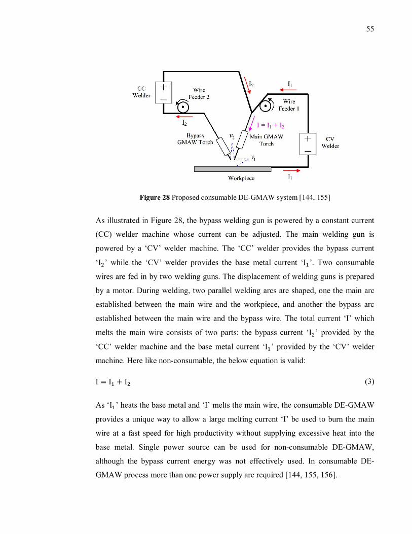
55
Figure 28 Proposed consumable DE-GMAW system [144, 155]
As illustrated in Figure 28, the bypass welding gun is powered by a constant current
(CC) welder machine whose current can be adjusted. The main welding gun is
powered by a ‘CV’ welder machine. The ‘CC’ welder provides the bypass current
‘I�’ while the ‘CV’ welder provides the base metal current ‘I�’. Two consumable
wires are fed in by two welding guns. The displacement of welding guns is prepared
by a motor. During welding, two parallel welding arcs are shaped, one the main arc
established between the main wire and the workpiece, and another the bypass arc
established between the main wire and the bypass wire. The total current ‘I’ which
melts the main wire consists of two parts: the bypass current ‘I�’ provided by the
‘CC’ welder machine and the base metal current ‘I�’ provided by the ‘CV’ welder
machine. Here like non-consumable, the below equation is valid:
I= I� + I� (3)
As ‘I�’ heats the base metal and ‘I’ melts the main wire, the consumable DE-GMAW
provides a unique way to allow a large melting current ‘I’ be used to burn the main
wire at a fast speed for high productivity without supplying excessive heat into the
base metal. Single power source can be used for non-consumable DE-GMAW,
although the bypass current energy was not effectively used. In consumable DE-
GMAW process more than one power supply are required [144, 155, 156].
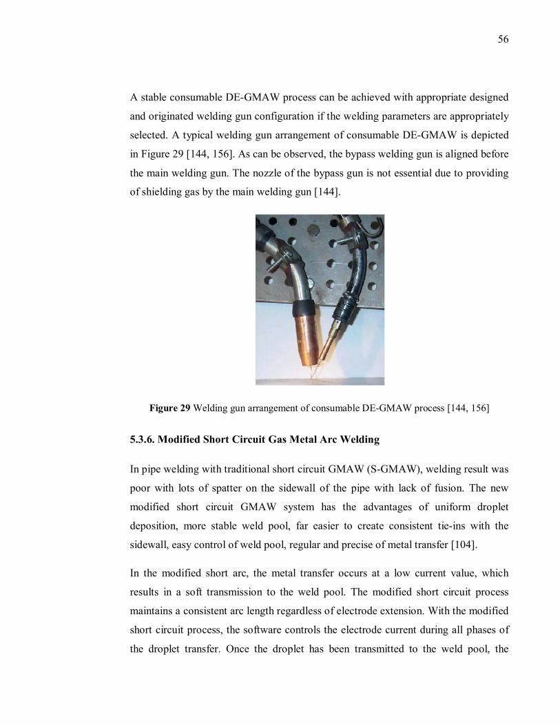
56
A stable consumable DE-GMAW process can be achieved with appropriate designed
and originated welding gun configuration if the welding parameters are appropriately
selected. A typical welding gun arrangement of consumable DE-GMAW is depicted
in Figure 29 [144, 156]. As can be observed, the bypass welding gun is aligned before
the main welding gun. The nozzle of the bypass gun is not essential due to providing
of shielding gas by the main welding gun [144].
Figure 29 Welding gun arrangement of consumable DE-GMAW process [144, 156]
5.3.6. Modified Short Circuit Gas Metal Arc Welding
In pipe welding with traditional short circuit GMAW (S-GMAW), welding result was
poor with lots of spatter on the sidewall of the pipe with lack of fusion. The new
modified short circuit GMAW system has the advantages of uniform droplet
deposition, more stable weld pool, far easier to create consistent tie-ins with the
sidewall, easy control of weld pool, regular and precise of metal transfer [104].
In the modified short arc, the metal transfer occurs at a low current value, which
results in a soft transmission to the weld pool. The modified short circuit process
maintains a consistent arc length regardless of electrode extension. With the modified
short circuit process, the software controls the electrode current during all phases of
the droplet transfer. Once the droplet has been transmitted to the weld pool, the
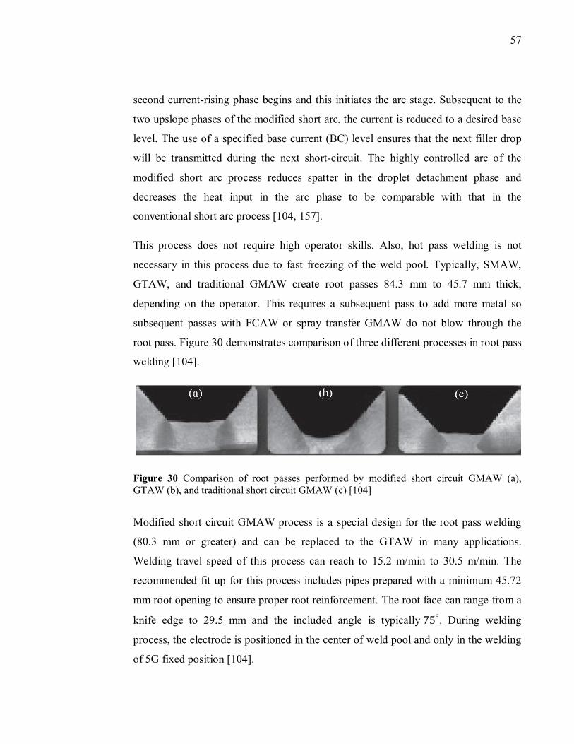
57
second current-rising phase begins and this initiates the arc stage. Subsequent to the
two upslope phases of the modified short arc, the current is reduced to a desired base
level. The use of a specified base current (BC) level ensures that the next filler drop
will be transmitted during the next short-circuit. The highly controlled arc of the
modified short arc process reduces spatter in the droplet detachment phase and
decreases the heat input in the arc phase to be comparable with that in the
conventional short arc process [104, 157].
This process does not require high operator skills. Also, hot pass welding is not
necessary in this process due to fast freezing of the weld pool. Typically, SMAW,
GTAW, and traditional GMAW create root passes 84.3 mm to 45.7 mm thick,
depending on the operator. This requires a subsequent pass to add more metal so
subsequent passes with FCAW or spray transfer GMAW do not blow through the
root pass. Figure 30 demonstrates comparison of three different processes in root pass
welding [104].
Figure 30 Comparison of root passes performed by modified short circuit GMAW (a), GTAW (b), and traditional short circuit GMAW (c) [104]
Modified short circuit GMAW process is a special design for the root pass welding
(80.3 mm or greater) and can be replaced to the GTAW in many applications.
Welding travel speed of this process can reach to 15.2 m/min to 30.5 m/min. The
recommended fit up for this process includes pipes prepared with a minimum 45.72
mm root opening to ensure proper root reinforcement. The root face can range from a
knife edge to 29.5 mm and the included angle is typically75°. During welding
process, the electrode is positioned in the center of weld pool and only in the welding
of 5G fixed position [104].
58
5.3.7. Pulsed Gas Metal Arc Welding (P-GMAW)
In this mode of transfer, in a fixed duration of time, the power source pulses rapidly
between a peak and background current. ‘CC’ is the most capable power source in
pulse welding operation instead of using ‘CV’ [158]. This method is a variation of
constant current welding which involves cycling of the welding current from a high
to a low level at a selected regular frequency [159, 160].
Spray pulsed transfer occurs during the peak current period and the small molten
droplets detach the electrode in a spray form. By increasing the pulse frequency, the
size of droplets decreased and the metal transfer rate increased. Typically, the rate of
frequency is between 60 to 120 Hz but this amount can go further [161].
The square wave graph of current versus time in pulsed arc is shown in Figure 31
[126]. During metal transfer the current reaches its higher value known as peak
current ‘I�’ and the lowest amount of current is known as background current ‘I�’.
The other primary parameters of a rectangular current pulse are pulse duration or
pulse time ‘t�’, pulse off-time or background time ‘t�’, and pulse frequency ‘f ’. The
power supplies in this mode of transfer pulse the current back and forth between the
globular and spray transfer current range to transfer the metal (see Figure 31) [126].
The arc is kept establish during background current typically at very low currents
between 20 to 40 A. The metal transfer from consumable electrode in this mode is
obtained in two ways depending upon the welding current: First, when the current is
below, a certain critical current producing a globular mode (10 drops per second or
low). Second, when the current is above the critical current, spray mode produced (a
few hundred drops per second). The critical current as mentioned is so called
transition current [104, 126].
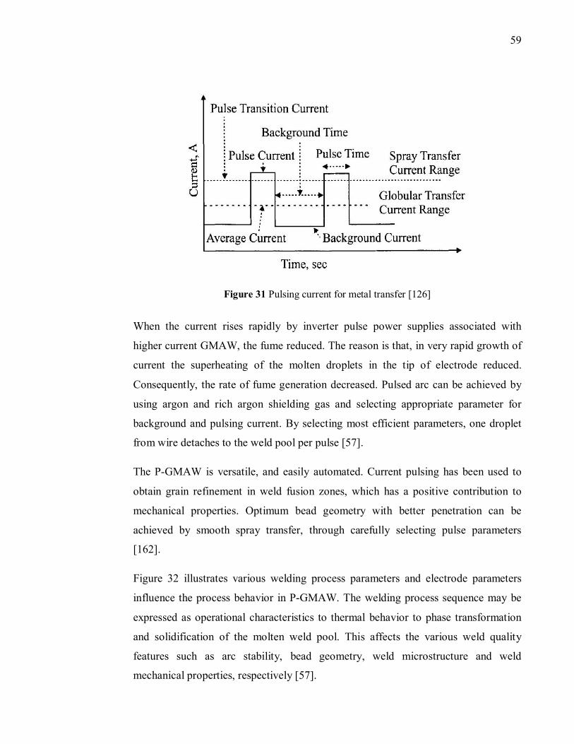
59
Figure 31 Pulsing current for metal transfer [126]
When the current rises rapidly by inverter pulse power supplies associated with
higher current GMAW, the fume reduced. The reason is that, in very rapid growth of
current the superheating of the molten droplets in the tip of electrode reduced.
Consequently, the rate of fume generation decreased. Pulsed arc can be achieved by
using argon and rich argon shielding gas and selecting appropriate parameter for
background and pulsing current. By selecting most efficient parameters, one droplet
from wire detaches to the weld pool per pulse [57].
The P-GMAW is versatile, and easily automated. Current pulsing has been used to
obtain grain refinement in weld fusion zones, which has a positive contribution to
mechanical properties. Optimum bead geometry with better penetration can be
achieved by smooth spray transfer, through carefully selecting pulse parameters
[162].
Figure 32 illustrates various welding process parameters and electrode parameters
influence the process behavior in P-GMAW. The welding process sequence may be
expressed as operational characteristics to thermal behavior to phase transformation
and solidification of the molten weld pool. This affects the various weld quality
features such as arc stability, bead geometry, weld microstructure and weld
mechanical properties, respectively [57].
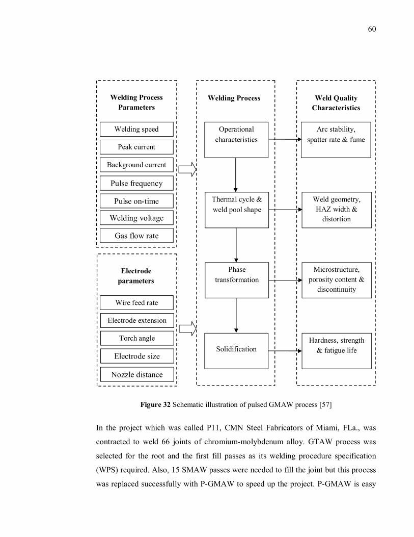
60
Figure 32 Schematic illustration of pulsed GMAW process [57]
In the project which was called P11, CMN Steel Fabricators of Miami, FLa., was
contracted to weld 66 joints of chromium-molybdenum alloy. GTAW process was
selected for the root and the first fill passes as its welding procedure specification
(WPS) required. Also, 15 SMAW passes were needed to fill the joint but this process
was replaced successfully with P-GMAW to speed up the project. P-GMAW is easy
Weld Quality
Characteristics
Arc stability,
spatter rate & fume
Weld geometry,
HAZ width &
distortion
Microstructure,
porosity content &
discontinuity
Hardness, strength
& fatigue life
Welding Process
Operational
characteristics
Thermal cycle &
weld pool shape
Phase
transformation
Solidification
Welding Process
Parameters
Welding speed
Peak current
Background current
Pulse frequency
Pulse on-time
Welding voltage
Gas flow rate
Electrode
parameters
Wire feed rate
Electrode extension
Torch angle
Electrode size
Nozzle distance
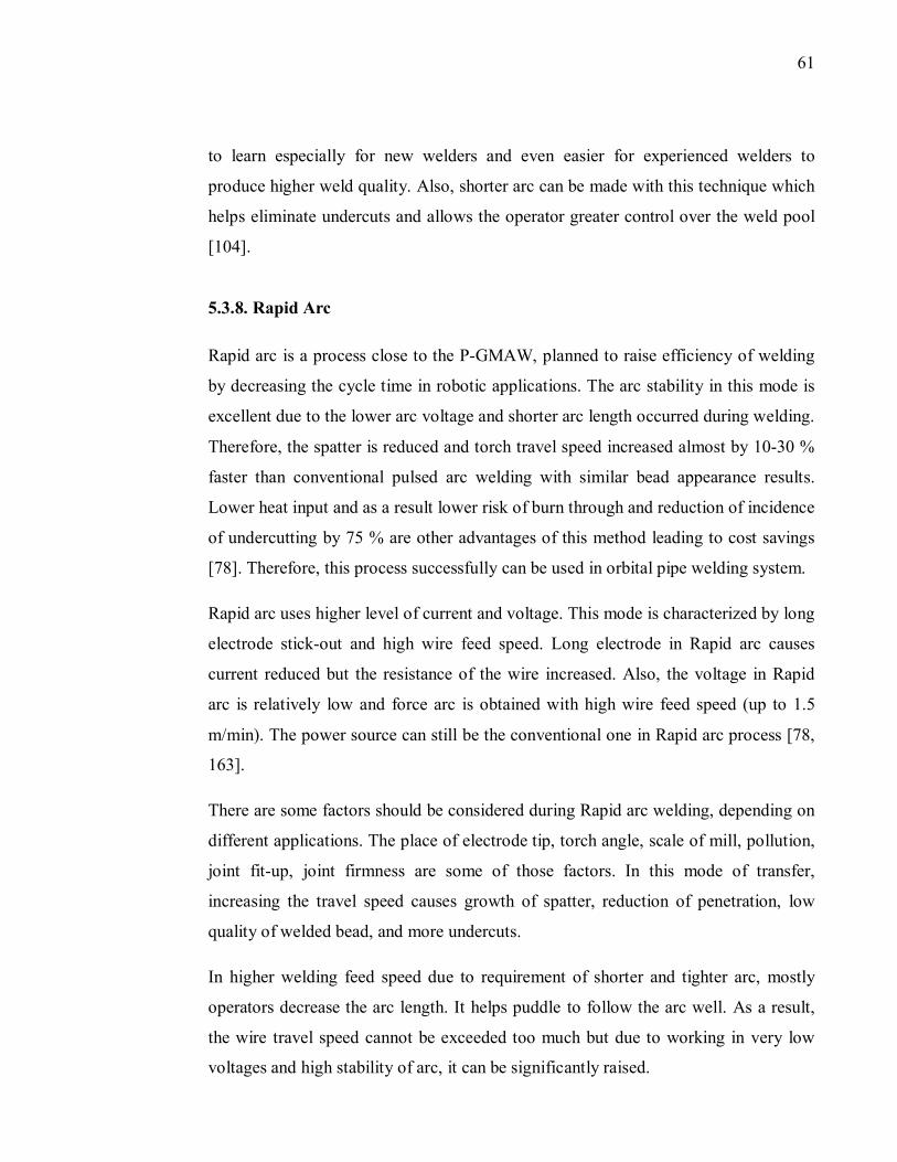
61
to learn especially for new welders and even easier for experienced welders to
produce higher weld quality. Also, shorter arc can be made with this technique which
helps eliminate undercuts and allows the operator greater control over the weld pool
[104].
5.3.8. Rapid Arc
Rapid arc is a process close to the P-GMAW, planned to raise efficiency of welding
by decreasing the cycle time in robotic applications. The arc stability in this mode is
excellent due to the lower arc voltage and shorter arc length occurred during welding.
Therefore, the spatter is reduced and torch travel speed increased almost by 10-30 %
faster than conventional pulsed arc welding with similar bead appearance results.
Lower heat input and as a result lower risk of burn through and reduction of incidence
of undercutting by 75 % are other advantages of this method leading to cost savings
[78]. Therefore, this process successfully can be used in orbital pipe welding system.
Rapid arc uses higher level of current and voltage. This mode is characterized by long
electrode stick-out and high wire feed speed. Long electrode in Rapid arc causes
current reduced but the resistance of the wire increased. Also, the voltage in Rapid
arc is relatively low and force arc is obtained with high wire feed speed (up to 1.5
m/min). The power source can still be the conventional one in Rapid arc process [78,
163].
There are some factors should be considered during Rapid arc welding, depending on
different applications. The place of electrode tip, torch angle, scale of mill, pollution,
joint fit-up, joint firmness are some of those factors. In this mode of transfer,
increasing the travel speed causes growth of spatter, reduction of penetration, low
quality of welded bead, and more undercuts.
In higher welding feed speed due to requirement of shorter and tighter arc, mostly
operators decrease the arc length. It helps puddle to follow the arc well. As a result,
the wire travel speed cannot be exceeded too much but due to working in very low
voltages and high stability of arc, it can be significantly raised.
62
Metal core wire can produce smaller weld beads and wire with diameter of 1.6 mm
causes improvement of fit-up tolerance and growth of edge wetting. Short circuit in
Rapid arc occurs in low current with the help of waveform controlling of arc
adjustment. This waveform can be divided into the four main sections as shown in
Figure 33 [78].
Figure 33 Schematic of Rapid arc’s waveform and its principle [78]
In section “Pulse”, the current rises rapidly and it increases the arc energy and molten
droplet created at the tip of electrode. In “Puddle Rise” step, current decreased
rapidly, the arc force is cut and it causes puddle raised up in the direction of droplet.
In third step called “Short”, the arc suddenly falls apart and the droplet touches the
molten weld pool. Finally, in “Puddle Repulsion” step, the electrode is conditioned
due to the soft plasma rising which forces the puddle away. This makes guarantee that
molten metal transferred to the weld pool in a stable rhythm in each period.
The cycle time decreased almost 10-30 % because of higher speed of the wire feed.
Therefore, the process done faster and it causes higher efficiency, and as a result
63
lower investment. Beside, this process needs lower post processing because of lower
spatter level [78].
5.3.9. Surface Tension Transfer (STT)
STT is a controlled-current GMAW process invented by Lincoln Electric Company
that uses high-frequency inverter technology and waveform control [62]. This process
is quite close to the short arc with better control into the power source to increase the
weld quality [158, 164]. One characteristic of this mode is slower deposition rate but
higher weld quality with almost no spatters. Sophisticated controlling and electronic
technical methods is employed in this process to have the best combination of short
arc and GTAW process. STT has the ability of controlling the current without
dependence on wire feed speed. During all phases of welding cycle, the welding
current is adjusted to the heat requirements allocate by the arc [165].
The current is controlled in STT to make heat input independent of wire feed speed.
As a result, electrode extension changes have no effect to heat. Distortion, spatter,
and fume is decreased in this mode of transfer due to the less overheating of
electrode, even with larger diameter of electrode and 100 % CO� shielding gas.
Larger wire and 100 % CO� shielding gas together reduce the welding costs. Molten
material of the electrode touches the weld pool before detachment occurred [166].
This job is done through a high speed inverter, during the whole shorting period to
modify the output current waveform and well known as “Waveform Control
Technology”. With this method in STT, power source can be programmed to improve
efficiency of arc characteristics for each application [164].
The arc current range of all conventional transfer modes in FCAW are 90 to 400 A
with voltage variation of 10 to 40 V. In STT process, current rate and wire feed speed
are not related to each other. Current controller is used in this mode to adapt heat
without dependence on the wire feed speed, so by changing the electrode extension
nothing happens to heat [167]. Typically, waveform cycle repeated every 1/120
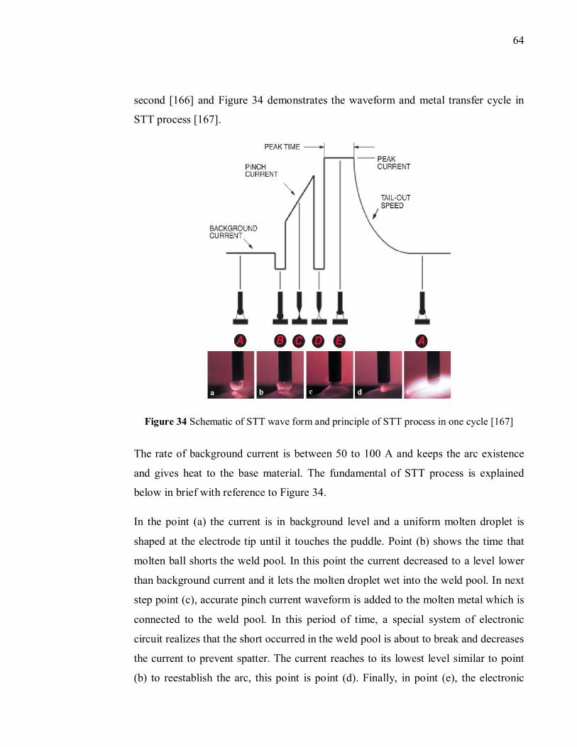
64
second [166] and Figure 34 demonstrates the waveform and metal transfer cycle in
STT process [167].
Figure 34 Schematic of STT wave form and principle of STT process in one cycle [167]
The rate of background current is between 50 to 100 A and keeps the arc existence
and gives heat to the base material. The fundamental of STT process is explained
below in brief with reference to Figure 34.
In the point (a) the current is in background level and a uniform molten droplet is
shaped at the electrode tip until it touches the puddle. Point (b) shows the time that
molten ball shorts the weld pool. In this point the current decreased to a level lower
than background current and it lets the molten droplet wet into the weld pool. In next
step point (c), accurate pinch current waveform is added to the molten metal which is
connected to the weld pool. In this period of time, a special system of electronic
circuit realizes that the short occurred in the weld pool is about to break and decreases
the current to prevent spatter. The current reaches to its lowest level similar to point
(b) to reestablish the arc, this point is point (d). Finally, in point (e), the electronic
65
circuit system (circuitry) by sensing the reestablishment of arc, increases the current
of arc to the peak current automatically, to produce the proper arc length. This peak
current, goes to the background current by tail-out control. The rate that the current is
changed from peak current to background current is adapted by tail-out control.
In STT welding, parameters such as background current, peak current, and tail-out
influence the whole welding process. Good fusion is guaranteed by arc length which
is depended on the peak current. Higher arc length is obtained by higher peak current.
Too large arc length may cause globular transfer. Too small arc length may be occur
arc instability and wire stubbing. The heat input to the weld is controlled by
background current. When the amount of background current is high, the weld bead
will be flat. Unlike, by decreasing this amount, taller rounded contour will be
obtained. Additional power is provided by tail-out while the size of molten droplet
does not go too large [167].
STT process is three or four times faster than GTAW to complete open root welds in
pipe welding applications with better back beads and edge fusion without use of
ceramic or copper internal back up bars. Also, HAZ is reduced in this mode.
Distortion is minimized in this method compared to the conventional GMAW due to
the low heat input. Operating of this process is easier than others, yet produces
consistent, X-ray quality welds. The STT process results in a complete back bead
without shrinkage from the 12 to 6 O’clock weld positions. Also, because current
control is independent of wire feed speed, the process allows greater flexibility under
all conditions [18, 19, 77].
Obtained weld quality of STT is higher in all position due to better position in poor fit
up area. The input heat needed in this mode is lower and it makes less oxidization. By
precise controlling of the amperage in every moment of welding cycle, better fusion
is achieved. In STT process, because only required heat for weld is produced (lower
heat input), so less material distortion occurs. Possibility of using larger diameter of
wire, carbon dioxide shielding gas, and fewer spatters, all together reduce operation
cost and increase the welding efficiency of this process [77, 164, 167].
66
The process is effective for welding stainless steel and related alloys, as well as mild
and high-strength steels. 100 % of CO� and combination of CO� and argon can be
used as shielding gas in power source for mild steel as well as combination with
helium for stainless steel. Superior metallurgical properties can be achieved when
welding duplex stainless steel and the “critical pitting temperature” (CPT) is
significantly better with STT than with GTAW [18, 19, 77, 164].
The STT process has gained acceptance in open root pipe welding because it controls
the welding current independent to the wire feed speed. This feature makes
controlling of temperature or fluidity of the weld pool easier to guarantee penetration
and fusion. Lower amount of spatter dissipated on the pipe and surrounding fixtures
means more part of electrode spent into the weld pool and as a result this process is
more productive. This process find by welders not only easy to make open root welds
but also excellent mechanical and metallurgical properties [18, 19, 77]. Other
advanced processes in this category are, Fronius’s CMT, EWM’s cold arc and
Kemppi’s wise-process.
5.4. Laser Welding and Hybrid Laser Arc Welding
Hybrid welding refers to the combination of laser beam welding (LBW) with another
welding process to further improve productivity. HLAW was introduced to eliminate
drawbacks related to high-power pure laser welding. Laser beam welding has high
welding speed, high power density, low distortion, narrow weld joints, low thermal
load, single pass welding in large thickness, easy automation, and positive effects on
the working environment [168, 169].
Compared to laser welding, HLAW has greater ductility, deeper penetration, higher
bridgeability, higher process stability, lower laser beam power, lower fabrication time
and welding costs, lower energy consumption, higher welding speed at constant heat
input and distortion [168, 170].
67
On the other hand, advantages of arc welding process can be named as, higher
tolerance to fit-up, low-cost energy source, better mechanical properties, good root
opening bridgeability, and the facility for influencing the structure by adding filler
metals [171]. Then, by combining the laser process an arc welding process the result
is gaining broader acceptance within industry. This combination leads to advantages
over other methods such as T-GMAW and Rapid arc welding, such as lower heat
input, narrower weld joints, higher welding speed, higher thermal efficiency, better
mechanical properties, and possibility of direct, single-pass butt-welding of pipes
with little or no bevel requirement [149, 170, 172, 173, 174].
However, numerous advantages are involved with HLAW process; there are some
limitations for this technology, can be listed as [175]:
Almost new technology and risky
Laser hazard and requirement of protection equipments
To obtain high quality strict alignment and part fit-up are required
Costly process compared to conventional automated GMAW due to expensive
laser equipments
Difficulty in welding of thick-section butt joints with a gap exceeding 1 mm,
due to the small focal spot diameter of the laser beam
HLAW can be used to weld a wide range of metals, including steel, stainless steel,
nickel, titanium, aluminum, copper, and other alloy systems. This process can be used
in both, thin-section welding, such as automotive components [176], and thick-
section welding, such as oil and gas transmission pipelines, boiler manufacturing,
wind turbine towers, prefabricated steel beams, nuclear components, shipbuilding,
heavy vehicles, construction and mining equipment, and rail cars [149, 177]. There is
welding possibility of many joint designs with HLAW, such as butt, groove, lap,
flange, and fillet joints [168, 170, 175].
Continuous-wave lasers are most often used for HLAW because they generate a
constant laser power for the duration of the weld. The laser source is selected based
68
on power and wavelength. The output power capability is chosen based on the desired
weld penetration for a given application. Travel speed, power density, base-metal
absorptivity, and joint design can also affect the determination of laser power [175].
CO� lasers and Nd:YAG (Neodymium-doped: Yttrium Aluminum Garnet), diode, and
fiber lasers are main types of industrial lasers. CO� and Nd:YAG lasers have been
used at high powers for deep penetration keyhole welding. The main difference
between these to process in terms of materials processing is their wavelength of the
light emitted. Only the Nd:YAG lasers wavelength which are 1.06 μm can be carried
by an optical fiber to the workpiece, which allows circular geometries to be more
easily welded. CO� lasers have a wavelength of 10.64 μm and this is not transmittable
through glass. A series of mirrors or transmissive optical systems should be used to
transfer laser beam to the workpiece. Nd:YAG lasers have been more limited in terms
of power. Also, The beam quality of CO� lasers is better than that currently available
with high power Nd:YAG lasers. To use high power Nd:YAG laser, The Welding
Institute (TWI). Combined the beams from up to three Nd:YAG lasers to obtain one
laser beam up to 8.9 kW power that can be transferred to the workpiece by using
optical fiber with 1.0 mm diameter [16, 63, 171, 177].
Mostly, CO� laser welding systems are used in static and limited motion industrial
environments. One CO� laser welding system has been field tested by Bouyges
Offshore. This company developed a full production welding system based on a 12
kW laser. The system was introduced for welding of API 5L X52 pipeline with
dimension of 254 × 12.7mm in the 5G position. The system was easy to move and
install on different pipe lay vessels. With filler metal additions, the process was
tolerant to a maximum gap of 0.5 mm and a maximum internal misalignment of 2
mm [16, 63]. It should be noted that, in the welding of C-Mn steels for structural and
shipbuilding applications, CO� lasers has been taken [178].
As mentioned, the most important aspect of Nd:YAG laser is its possibility of transfer
by optical fiber. This feature as well as recent ability to produce high power Nd:YAG
laser beams make this method much more attractive as flexible manufacturing tools
69
and particularly for orbital welding of land pipelines [16, 177]. 1.5-2 kW Nd:YAG
lasers have been successfully containerized [179] and 4 kW Nd:YAG lasers are the
largest commercially available.
Nd:YAG laser is not a proper process for onshore pipeline welding applications due
to the plug efficiency, physical size and cooling requirements Nd:YAG lasers. From
the beginning of the “YAGPIPE” project this fact became well-known and it was
assumed that new laser technologies would develop over the course of the project and
that these may be suitable for pipeline applications [16, 177]. Also, weld bead shape
of joints welded by Nd:YAG laser are wider and varies with different cooling times.
This property of Nd:YAG laser system increase the risk of solidification cracking as
well as ability to produce tough, fine grained, autogenous fusion zone microstructures
[63].
Diode and fiber lasers are physically in small size with comparatively high wall plug
efficiencies. Compared to Nd:YAG laser, this method is 30 % more efficient with 50
% lower operating cost. Diode laser is easy to transport and this feature makes this
technology ideal for pipeline applications. The drawback of diode laser is their low
beam quality which eliminates possibility of keyhole welding. However,
manufacturers are working to increase power and improve beam quality and their
research leads to those energy densities over 2.5×10⁵ W/cm �. With this new diode
laser keyhole welding of steels up to 6 mm thickness is possible now [16, 180].
On the other hand, fiber lasers enables 50 % faster pipeline welding. Fiber lasers are
similar in concept to the end-pumped YAG lasers, with different in the shape of
optical fiber which is long. The core in fiber laser is doped with a laser medium
usually ytterbium (Yb) for oscillators or erbium (Er) for amplifiers. The size of fiber
core is generally lower than 10 μm with many meters of length, therefore beam
quality of fiber lasers is excellent [16, 181]. In the last six years, fiber lasers have
been used as a mobile application in shipbuilding and in the production of pipes
[182].
70
Mostly, fiber lasers are used in micro-applications which need low power but recently
4, 6, 8 kW units have been manufactured. Yb fiber lasers are now commercially
available with power levels of up to 10 kW. Yb fibers have special applications in
pipe girth welds due to the use of single optical fiber to transfer beam to the
workpiece. Also, their high efficiency enables the development of more portable
welding systems. In fiber lasers, electrical to optical efficiency can be over 20 % and
compared to Nd:YAG lasers lower input power or cooling is required [16, 177].
In the study [177] entirely feasibility of using high power laser welding of land
pipelines were proved and it can be the most promising technology for pipeline
applications in the future. This method used in orbital pipe welding for ensuring a
good weld at the start/stop weld overlap position. As an example, [IPG Photonics,
Oxford, Mass.,] claims that a 10 kW fiber laser that is part of a system for deep
penetration laser welding of pipeline steel, enable 50 % faster welding than current
technology. This process is used in welding of steel pipes like X70 and X90 thicker
than 10 mm which is used in oil and gas industries in one pass with high speed (2.2
m/min for X70) [16, 177, 181].
HLAW process combines a gas or solid-state laser (e.g., CO� or Nd:YAG) with an arc
welding process (e.g., GMAW, GTAW, or PAW) [183]. In the fully synergetic
hybrid processes the plasma formed at the interaction point of the laser on the
workpiece surface. Energy is transmitted from the laser to the arc by means of high-
energy infrared coherent radiation using a fiber optic cable. The focused laser beam
hits the workpiece surface converting its energy into heat. The arc transmits the heat
needed for welding by a high electric current flowing to the workpiece via an arc
column [168, 170, 184].
Figure 35 is a cross section of a penetration mode one pass hybrid weld conducted on
a 12.45 mm carbon steel square butt joint. This weld was performed with 10 kW of
laser power, a 333 mm laser spot size, and an 8.9 m/min wire feed speed for a 1.1 mm
diameter steel wire at a travel speed of 1.52 m/min. Note that, the fusion zone
resembles the superposition of a GMAW weld profile and a laser weld profile [175].
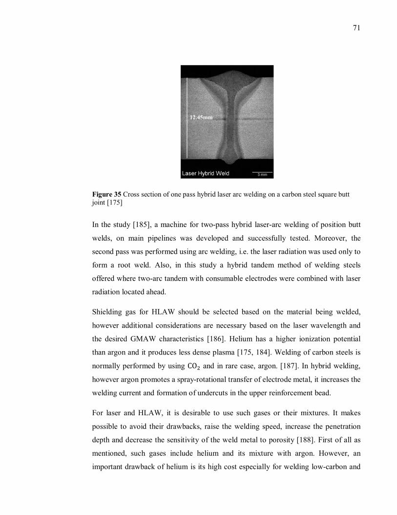
71
Figure 35 Cross section of one pass hybrid laser arc welding on a carbon steel square butt joint [175]
In the study [185], a machine for two-pass hybrid laser-arc welding of position butt
welds, on main pipelines was developed and successfully tested. Moreover, the
second pass was performed using arc welding, i.e. the laser radiation was used only to
form a root weld. Also, in this study a hybrid tandem method of welding steels
offered where two-arc tandem with consumable electrodes were combined with laser
radiation located ahead.
Shielding gas for HLAW should be selected based on the material being welded,
however additional considerations are necessary based on the laser wavelength and
the desired GMAW characteristics [186]. Helium has a higher ionization potential
than argon and it produces less dense plasma [175, 184]. Welding of carbon steels is
normally performed by using CO� and in rare case, argon. [187]. In hybrid welding,
however argon promotes a spray-rotational transfer of electrode metal, it increases the
welding current and formation of undercuts in the upper reinforcement bead.
For laser and HLAW, it is desirable to use such gases or their mixtures. It makes
possible to avoid their drawbacks, raise the welding speed, increase the penetration
depth and decrease the sensitivity of the weld metal to porosity [188]. First of all as
mentioned, such gases include helium and its mixture with argon. However, an
important drawback of helium is its high cost especially for welding low-carbon and
12.45mm
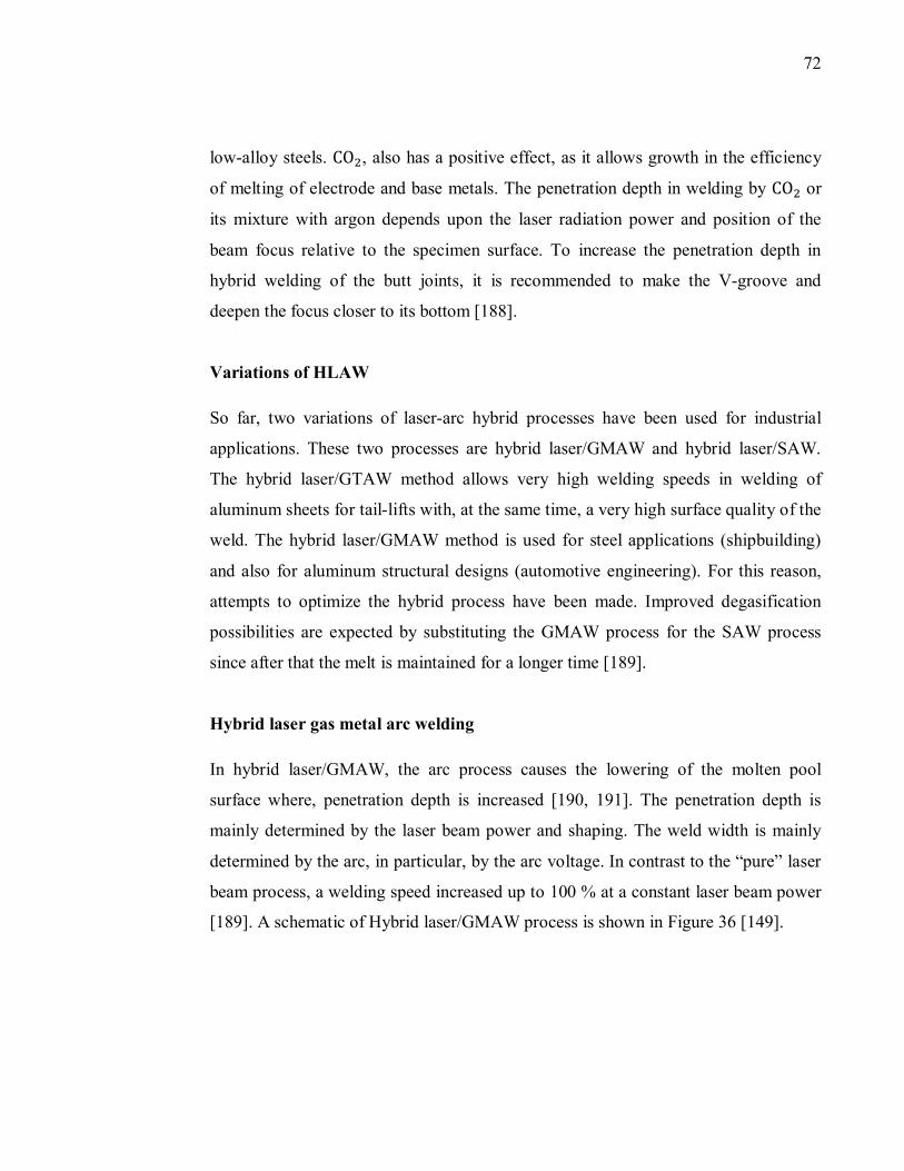
72
low-alloy steels. CO�, also has a positive effect, as it allows growth in the efficiency
of melting of electrode and base metals. The penetration depth in welding by CO� or
its mixture with argon depends upon the laser radiation power and position of the
beam focus relative to the specimen surface. To increase the penetration depth in
hybrid welding of the butt joints, it is recommended to make the V-groove and
deepen the focus closer to its bottom [188].
Variations of HLAW
So far, two variations of laser-arc hybrid processes have been used for industrial
applications. These two processes are hybrid laser/GMAW and hybrid laser/SAW.
The hybrid laser/GTAW method allows very high welding speeds in welding of
aluminum sheets for tail-lifts with, at the same time, a very high surface quality of the
weld. The hybrid laser/GMAW method is used for steel applications (shipbuilding)
and also for aluminum structural designs (automotive engineering). For this reason,
attempts to optimize the hybrid process have been made. Improved degasification
possibilities are expected by substituting the GMAW process for the SAW process
since after that the melt is maintained for a longer time [189].
Hybrid laser gas metal arc welding
In hybrid laser/GMAW, the arc process causes the lowering of the molten pool
surface where, penetration depth is increased [190, 191]. The penetration depth is
mainly determined by the laser beam power and shaping. The weld width is mainly
determined by the arc, in particular, by the arc voltage. In contrast to the “pure” laser
beam process, a welding speed increased up to 100 % at a constant laser beam power
[189]. A schematic of Hybrid laser/GMAW process is shown in Figure 36 [149].
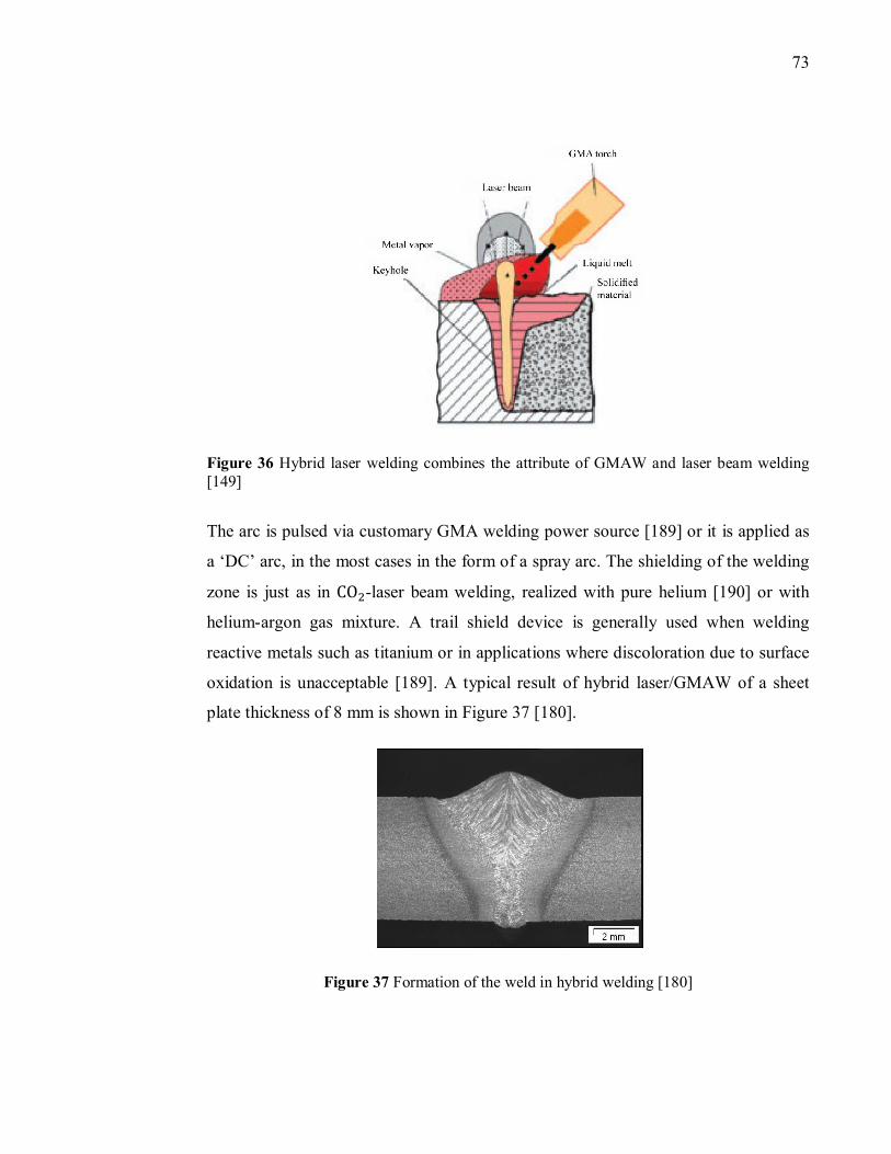
73
Figure 36 Hybrid laser welding combines the attribute of GMAW and laser beam welding [149]
The arc is pulsed via customary GMA welding power source [189] or it is applied as
a ‘DC’ arc, in the most cases in the form of a spray arc. The shielding of the welding
zone is just as in CO�-laser beam welding, realized with pure helium [190] or with
helium-argon gas mixture. A trail shield device is generally used when welding
reactive metals such as titanium or in applications where discoloration due to surface
oxidation is unacceptable [189]. A typical result of hybrid laser/GMAW of a sheet
plate thickness of 8 mm is shown in Figure 37 [180].
Figure 37 Formation of the weld in hybrid welding [180]
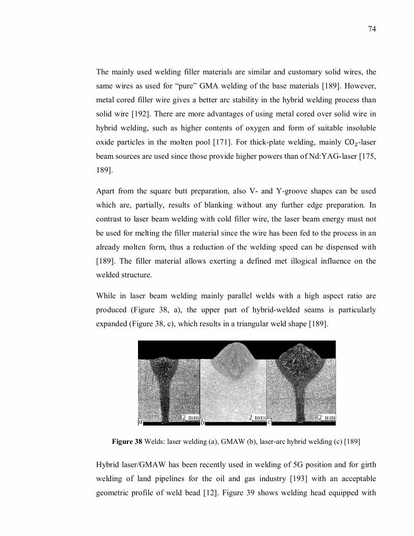
74
The mainly used welding filler materials are similar and customary solid wires, the
same wires as used for “pure” GMA welding of the base materials [189]. However,
metal cored filler wire gives a better arc stability in the hybrid welding process than
solid wire [192]. There are more advantages of using metal cored over solid wire in
hybrid welding, such as higher contents of oxygen and form of suitable insoluble
oxide particles in the molten pool [171]. For thick-plate welding, mainly CO�-laser
beam sources are used since those provide higher powers than of Nd:YAG-laser [175,
189].
Apart from the square butt preparation, also V- and Y-groove shapes can be used
which are, partially, results of blanking without any further edge preparation. In
contrast to laser beam welding with cold filler wire, the laser beam energy must not
be used for melting the filler material since the wire has been fed to the process in an
already molten form, thus a reduction of the welding speed can be dispensed with
[189]. The filler material allows exerting a defined met illogical influence on the
welded structure.
While in laser beam welding mainly parallel welds with a high aspect ratio are
produced (Figure 38, a), the upper part of hybrid-welded seams is particularly
expanded (Figure 38, c), which results in a triangular weld shape [189].
Figure 38 Welds: laser welding (a), GMAW (b), laser-arc hybrid welding (c) [189]
Hybrid laser/GMAW has been recently used in welding of 5G position and for girth
welding of land pipelines for the oil and gas industry [193] with an acceptable
geometric profile of weld bead [12]. Figure 39 shows welding head equipped with
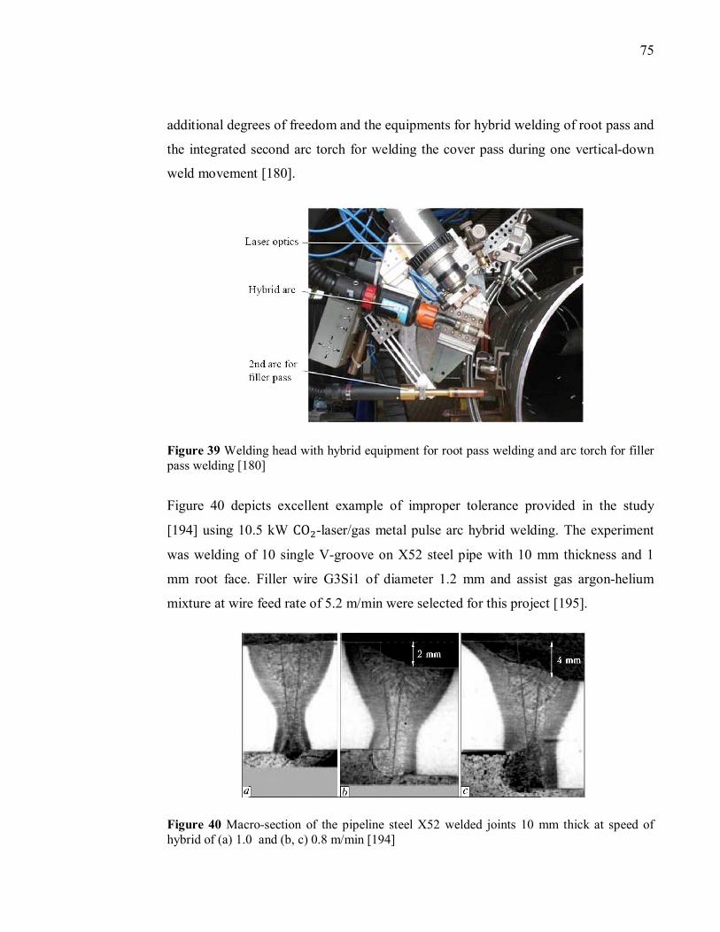
75
additional degrees of freedom and the equipments for hybrid welding of root pass and
the integrated second arc torch for welding the cover pass during one vertical-down
weld movement [180].
Figure 39 Welding head with hybrid equipment for root pass welding and arc torch for filler pass welding [180]
Figure 40 depicts excellent example of improper tolerance provided in the study
[194] using 10.5 kW CO�-laser/gas metal pulse arc hybrid welding. The experiment
was welding of 10 single V-groove on X52 steel pipe with 10 mm thickness and 1
mm root face. Filler wire G3Si1 of diameter 1.2 mm and assist gas argon-helium
mixture at wire feed rate of 5.2 m/min were selected for this project [195].
Figure 40 Macro-section of the pipeline steel X52 welded joints 10 mm thick at speed of hybrid of (a) 1.0 and (b, c) 0.8 m/min [194]
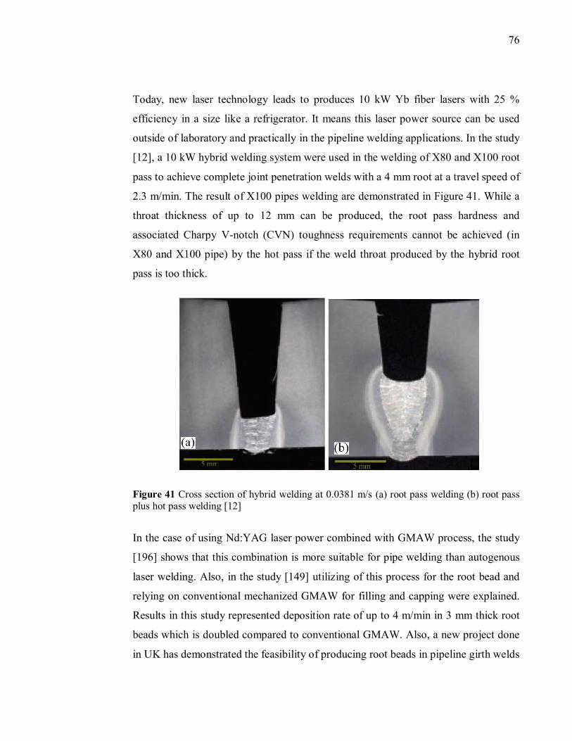
76
Today, new laser technology leads to produces 10 kW Yb fiber lasers with 25 %
efficiency in a size like a refrigerator. It means this laser power source can be used
outside of laboratory and practically in the pipeline welding applications. In the study
[12], a 10 kW hybrid welding system were used in the welding of X80 and X100 root
pass to achieve complete joint penetration welds with a 4 mm root at a travel speed of
2.3 m/min. The result of X100 pipes welding are demonstrated in Figure 41. While a
throat thickness of up to 12 mm can be produced, the root pass hardness and
associated Charpy V-notch (CVN) toughness requirements cannot be achieved (in
X80 and X100 pipe) by the hot pass if the weld throat produced by the hybrid root
pass is too thick.
Figure 41 Cross section of hybrid welding at 0.0381 m/s (a) root pass welding (b) root pass plus hot pass welding [12]
In the case of using Nd:YAG laser power combined with GMAW process, the study
[196] shows that this combination is more suitable for pipe welding than autogenous
laser welding. Also, in the study [149] utilizing of this process for the root bead and
relying on conventional mechanized GMAW for filling and capping were explained.
Results in this study represented deposition rate of up to 4 m/min in 3 mm thick root
beads which is doubled compared to conventional GMAW. Also, a new project done
in UK has demonstrated the feasibility of producing root beads in pipeline girth welds
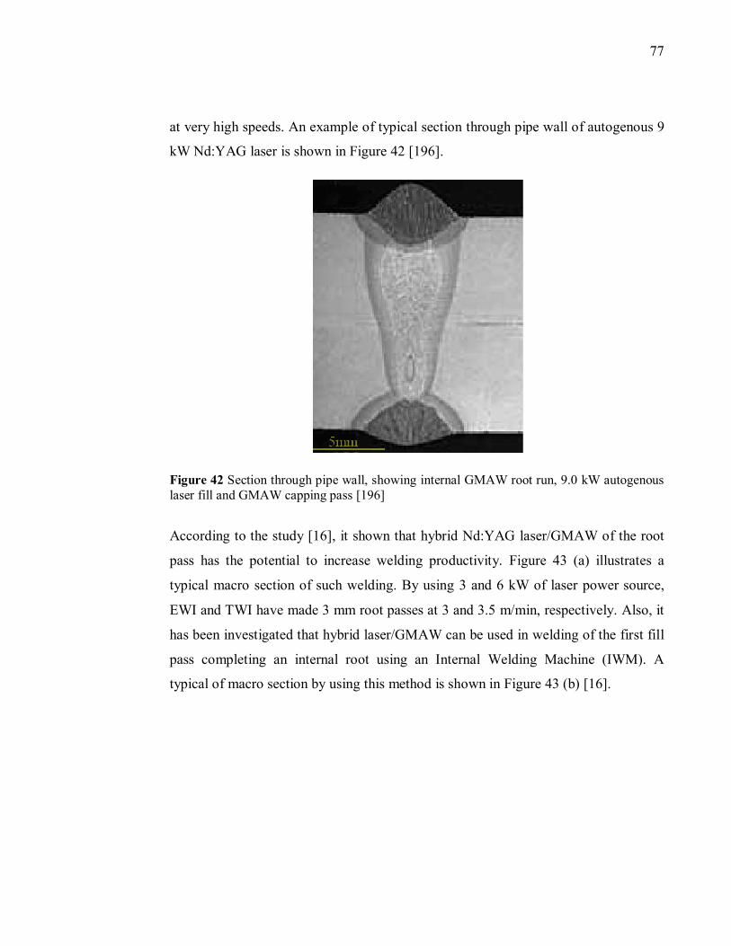
77
at very high speeds. An example of typical section through pipe wall of autogenous 9
kW Nd:YAG laser is shown in Figure 42 [196].
Figure 42 Section through pipe wall, showing internal GMAW root run, 9.0 kW autogenous laser fill and GMAW capping pass [196]
According to the study [16], it shown that hybrid Nd:YAG laser/GMAW of the root
pass has the potential to increase welding productivity. Figure 43 (a) illustrates a
typical macro section of such welding. By using 3 and 6 kW of laser power source,
EWI and TWI have made 3 mm root passes at 3 and 3.5 m/min, respectively. Also, it
has been investigated that hybrid laser/GMAW can be used in welding of the first fill
pass completing an internal root using an Internal Welding Machine (IWM). A
typical of macro section by using this method is shown in Figure 43 (b) [16].
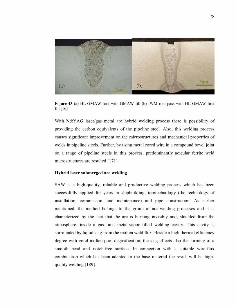
78
Figure 43 (a) HL-GMAW root with GMAW fill (b) IWM root pass with HL-GMAW first fill [16]
With Nd:YAG laser/gas metal arc hybrid welding process there is possibility of
providing the carbon equivalents of the pipeline steel. Also, this welding process
causes significant improvement on the microstructures and mechanical properties of
welds in pipeline steels. Further, by using metal cored wire in a compound bevel joint
on a range of pipeline steels in this process, predominantly acicular ferrite weld
microstructures are resulted [171].
Hybrid laser submerged arc welding
SAW is a high-quality, reliable and productive welding process which has been
successfully applied for years in shipbuilding, terotechnology (the technology of
installation, commission, and maintenance) and pipe construction. As earlier
mentioned, the method belongs to the group of arc welding processes and it is
characterized by the fact that the arc is burning invisibly and, shielded from the
atmosphere, inside a gas- and metal-vapor filled welding cavity. This cavity is
surrounded by liquid slag from the molten weld flux. Beside a high thermal efficiency
degree with good molten pool degasification, the slag effects also the forming of a
smooth bead and notch-free surface. In connection with a suitable wire-flux
combination which has been adapted to the base material the result will be high-
quality welding [189].
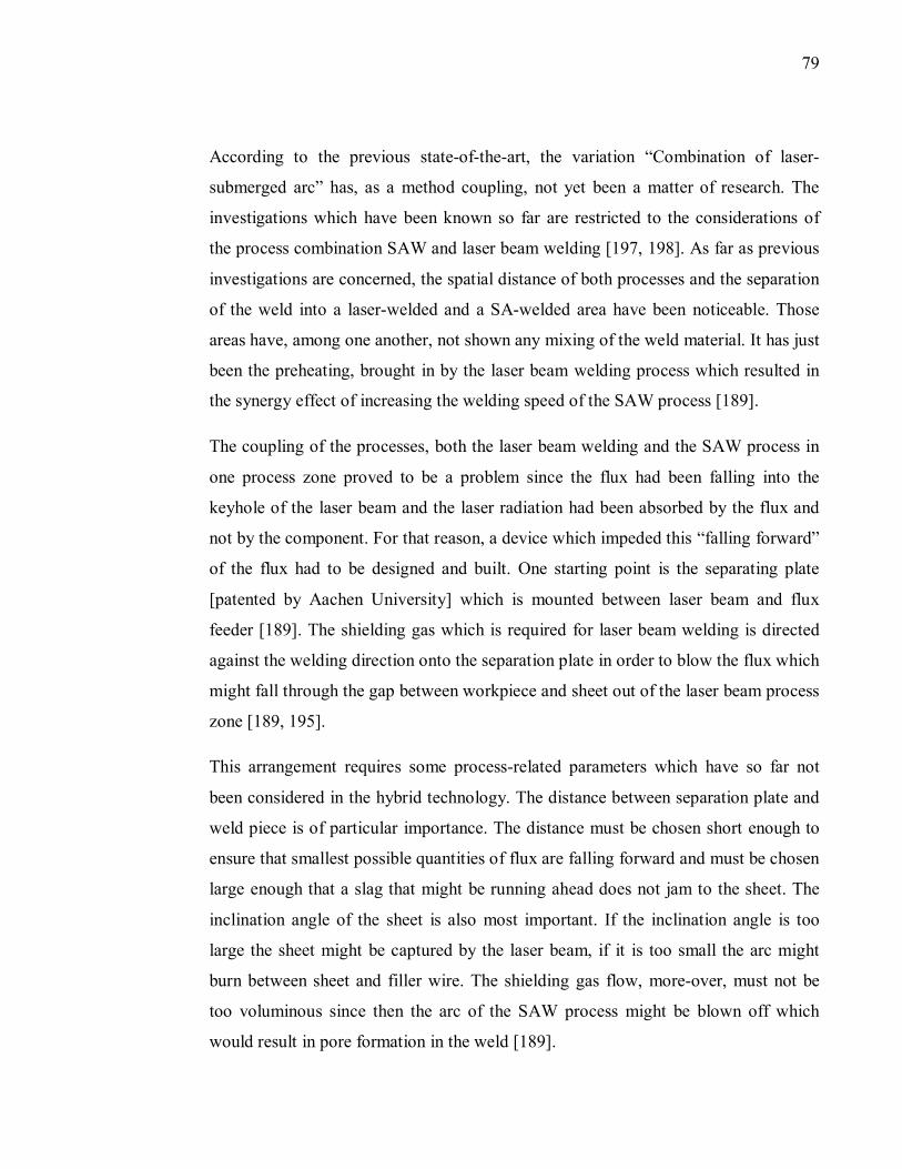
79
According to the previous state-of-the-art, the variation “Combination of laser-
submerged arc” has, as a method coupling, not yet been a matter of research. The
investigations which have been known so far are restricted to the considerations of
the process combination SAW and laser beam welding [197, 198]. As far as previous
investigations are concerned, the spatial distance of both processes and the separation
of the weld into a laser-welded and a SA-welded area have been noticeable. Those
areas have, among one another, not shown any mixing of the weld material. It has just
been the preheating, brought in by the laser beam welding process which resulted in
the synergy effect of increasing the welding speed of the SAW process [189].
The coupling of the processes, both the laser beam welding and the SAW process in
one process zone proved to be a problem since the flux had been falling into the
keyhole of the laser beam and the laser radiation had been absorbed by the flux and
not by the component. For that reason, a device which impeded this “falling forward”
of the flux had to be designed and built. One starting point is the separating plate
[patented by Aachen University] which is mounted between laser beam and flux
feeder [189]. The shielding gas which is required for laser beam welding is directed
against the welding direction onto the separation plate in order to blow the flux which
might fall through the gap between workpiece and sheet out of the laser beam process
zone [189, 195].
This arrangement requires some process-related parameters which have so far not
been considered in the hybrid technology. The distance between separation plate and
weld piece is of particular importance. The distance must be chosen short enough to
ensure that smallest possible quantities of flux are falling forward and must be chosen
large enough that a slag that might be running ahead does not jam to the sheet. The
inclination angle of the sheet is also most important. If the inclination angle is too
large the sheet might be captured by the laser beam, if it is too small the arc might
burn between sheet and filler wire. The shielding gas flow, more-over, must not be
too voluminous since then the arc of the SAW process might be blown off which
would result in pore formation in the weld [189].
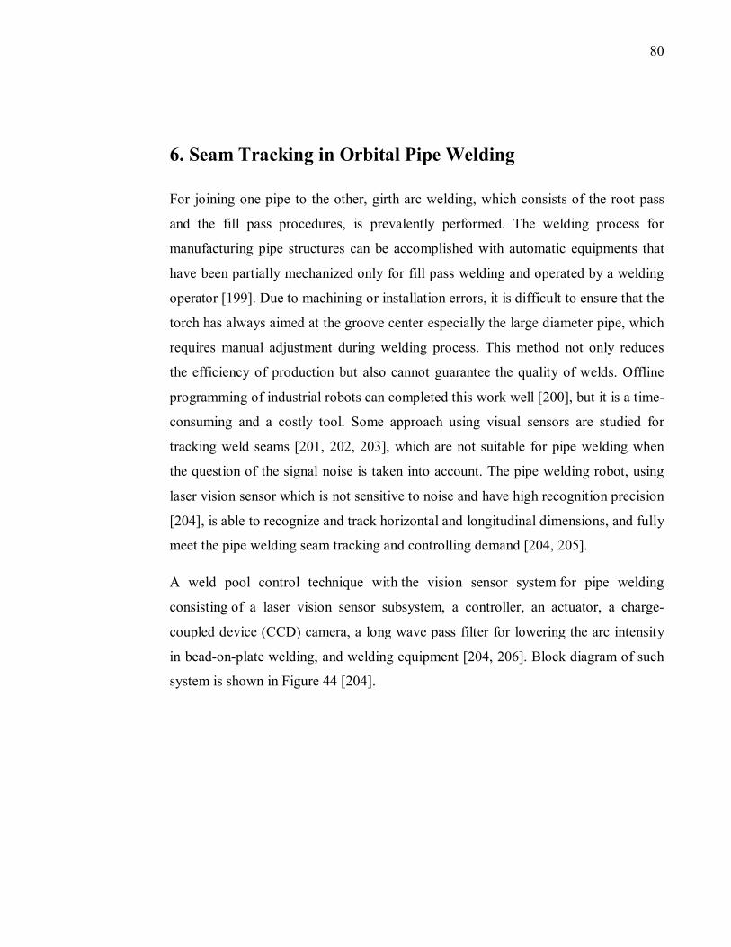
80
6. Seam Tracking in Orbital Pipe Welding
For joining one pipe to the other, girth arc welding, which consists of the root pass
and the fill pass procedures, is prevalently performed. The welding process for
manufacturing pipe structures can be accomplished with automatic equipments that
have been partially mechanized only for fill pass welding and operated by a welding
operator [199]. Due to machining or installation errors, it is difficult to ensure that the
torch has always aimed at the groove center especially the large diameter pipe, which
requires manual adjustment during welding process. This method not only reduces
the efficiency of production but also cannot guarantee the quality of welds. Offline
programming of industrial robots can completed this work well [200], but it is a time-
consuming and a costly tool. Some approach using visual sensors are studied for
tracking weld seams [201, 202, 203], which are not suitable for pipe welding when
the question of the signal noise is taken into account. The pipe welding robot, using
laser vision sensor which is not sensitive to noise and have high recognition precision
[204], is able to recognize and track horizontal and longitudinal dimensions, and fully
meet the pipe welding seam tracking and controlling demand [204, 205].
A weld pool control technique with the vision sensor system for pipe welding
consisting of a laser vision sensor subsystem, a controller, an actuator, a charge-
coupled device (CCD) camera, a long wave pass filter for lowering the arc intensity
in bead-on-plate welding, and welding equipment [204, 206]. Block diagram of such
system is shown in Figure 44 [204].
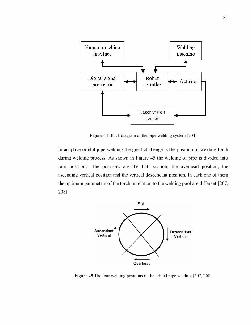
81
Figure 44 Block diagram of the pipe welding system [204]
In adaptive orbital pipe welding the great challenge is the position of welding torch
during welding process. As shown in Figure 45 the welding of pipe is divided into
four positions. The positions are the flat position, the overhead position, the
ascending vertical position and the vertical descendant position. In each one of them
the optimum parameters of the torch in relation to the welding pool are different [207,
208].
Figure 45 The four welding positions in the orbital pipe welding [207, 208]
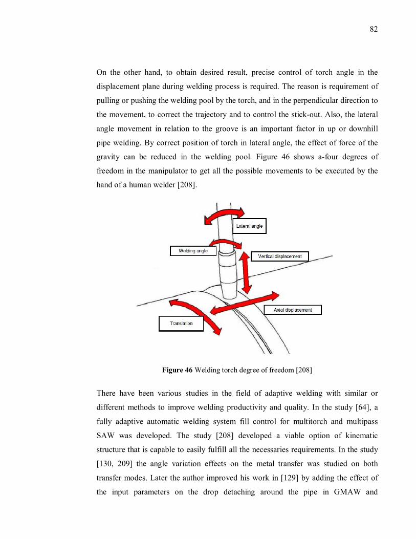
82
On the other hand, to obtain desired result, precise control of torch angle in the
displacement plane during welding process is required. The reason is requirement of
pulling or pushing the welding pool by the torch, and in the perpendicular direction to
the movement, to correct the trajectory and to control the stick-out. Also, the lateral
angle movement in relation to the groove is an important factor in up or downhill
pipe welding. By correct position of torch in lateral angle, the effect of force of the
gravity can be reduced in the welding pool. Figure 46 shows a-four degrees of
freedom in the manipulator to get all the possible movements to be executed by the
hand of a human welder [208].
Figure 46 Welding torch degree of freedom [208]
There have been various studies in the field of adaptive welding with similar or
different methods to improve welding productivity and quality. In the study [64], a
fully adaptive automatic welding system fill control for multitorch and multipass
SAW was developed. The study [208] developed a viable option of kinematic
structure that is capable to easily fulfill all the necessaries requirements. In the study
[130, 209] the angle variation effects on the metal transfer was studied on both
transfer modes. Later the author improved his work in [129] by adding the effect of
the input parameters on the drop detaching around the pipe in GMAW and
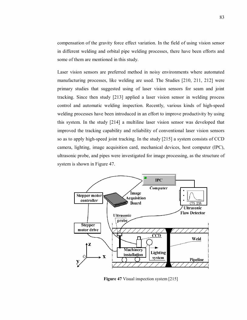
83
compensation of the gravity force effect variation. In the field of using vision sensor
in different welding and orbital pipe welding processes, there have been efforts and
some of them are mentioned in this study.
Laser vision sensors are preferred method in noisy environments where automated
manufacturing processes, like welding are used. The Studies [210, 211, 212] were
primary studies that suggested using of laser vision sensors for seam and joint
tracking. Since then study [213] applied a laser vision sensor in welding process
control and automatic welding inspection. Recently, various kinds of high-speed
welding processes have been introduced in an effort to improve productivity by using
this system. In the study [214] a multiline laser vision sensor was developed that
improved the tracking capability and reliability of conventional laser vision sensors
so as to apply high-speed joint tracking. In the study [215] a system consists of CCD
camera, lighting, image acquisition card, mechanical devices, host computer (IPC),
ultrasonic probe, and pipes were investigated for image processing, as the structure of
system is shown in Figure 47.
Figure 47 Visual inspection system [215]
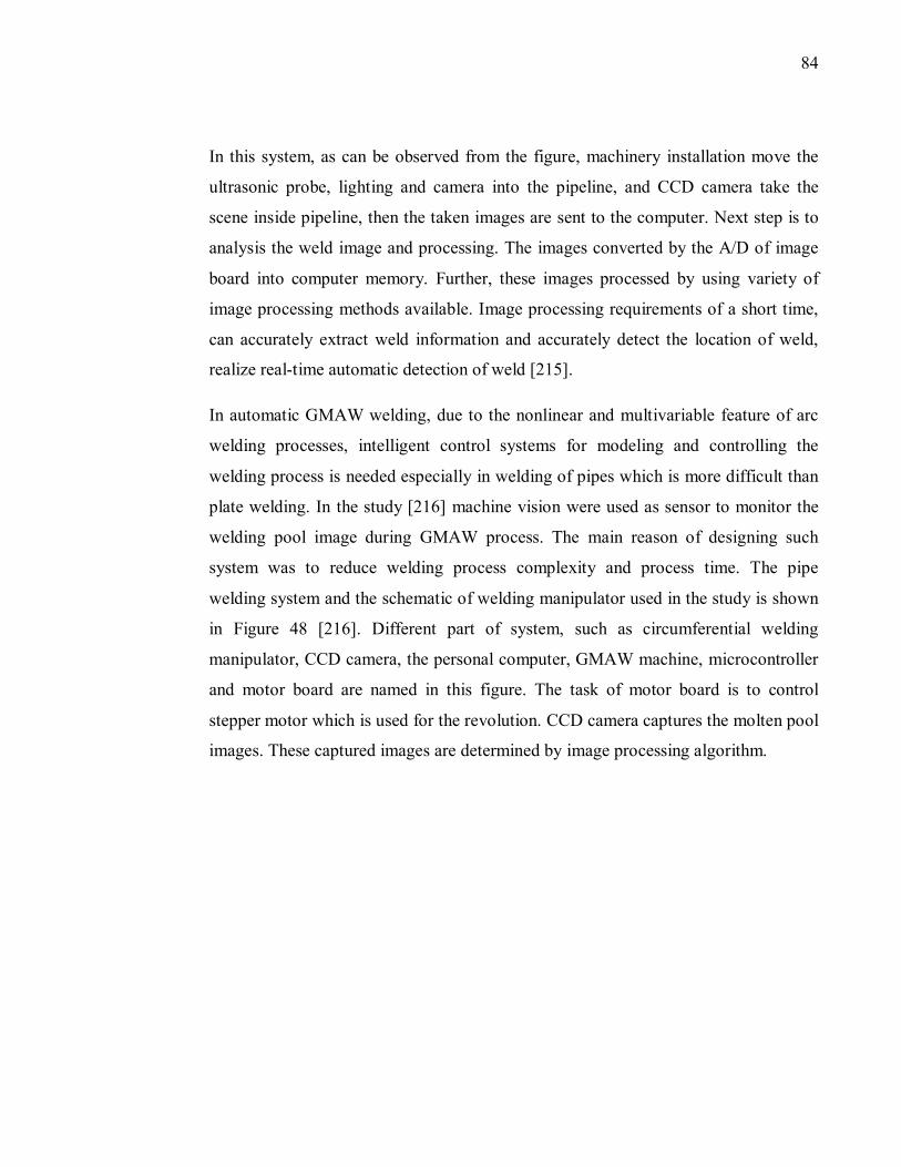
84
In this system, as can be observed from the figure, machinery installation move the
ultrasonic probe, lighting and camera into the pipeline, and CCD camera take the
scene inside pipeline, then the taken images are sent to the computer. Next step is to
analysis the weld image and processing. The images converted by the A/D of image
board into computer memory. Further, these images processed by using variety of
image processing methods available. Image processing requirements of a short time,
can accurately extract weld information and accurately detect the location of weld,
realize real-time automatic detection of weld [215].
In automatic GMAW welding, due to the nonlinear and multivariable feature of arc
welding processes, intelligent control systems for modeling and controlling the
welding process is needed especially in welding of pipes which is more difficult than
plate welding. In the study [216] machine vision were used as sensor to monitor the
welding pool image during GMAW process. The main reason of designing such
system was to reduce welding process complexity and process time. The pipe
welding system and the schematic of welding manipulator used in the study is shown
in Figure 48 [216]. Different part of system, such as circumferential welding
manipulator, CCD camera, the personal computer, GMAW machine, microcontroller
and motor board are named in this figure. The task of motor board is to control
stepper motor which is used for the revolution. CCD camera captures the molten pool
images. These captured images are determined by image processing algorithm.
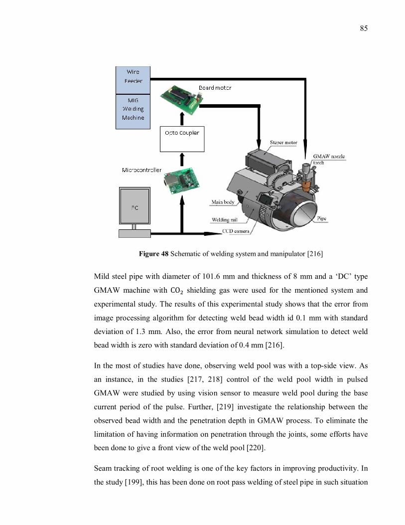
85
Figure 48 Schematic of welding system and manipulator [216]
Mild steel pipe with diameter of 101.6 mm and thickness of 8 mm and a ‘DC’ type
GMAW machine with CO� shielding gas were used for the mentioned system and
experimental study. The results of this experimental study shows that the error from
image processing algorithm for detecting weld bead width id 0.1 mm with standard
deviation of 1.3 mm. Also, the error from neural network simulation to detect weld
bead width is zero with standard deviation of 0.4 mm [216].
In the most of studies have done, observing weld pool was with a top-side view. As
an instance, in the studies [217, 218] control of the weld pool width in pulsed
GMAW were studied by using vision sensor to measure weld pool during the base
current period of the pulse. Further, [219] investigate the relationship between the
observed bead width and the penetration depth in GMAW process. To eliminate the
limitation of having information on penetration through the joints, some efforts have
been done to give a front view of the weld pool [220].
Seam tracking of root welding is one of the key factors in improving productivity. In
the study [199], this has been done on root pass welding of steel pipe in such situation
86
that pipe is rotating and welding head is fixed. The system consists of visual sensing
system composed of a CCD camera, lenses and filters, a frame grabber and image
processing algorithms as well as five-axis pipe welding manipulator with its
controller, the hardware logic for detecting the short-circuit and the visual sensing
system.
Figure 49 (a) illustrates the way that seam tracking process of this system works
[199]. As can be seen from the figure, the image needs to have the shadow of the wire
indicating current position of the torch, and the center of the weld pool presenting the
center of groove. First, to make finding of the center of groove possible, it is needed
to identify the left and right boundary of weld pool. From the mid column between
the left extreme column and the groove center to the mid one between the groove
center and the right extreme column, the gray level of each pixel located between a
pool start pixel and the pool center in the vertical direction for each column
were then added. Afterwards, the differentiation for the summation along the
horizontal direction was carried out to obtain minimal and maximal values, and their
column positions, respectively. As a result, the center of the torch could be then
determined to be located at the center of the two columns. An offset of the welding
wire from the center of a groove makes shapes of the weld pool at both sides around
the wire to be of asymmetry.
Figure 49 (a) Features extraction in weld pool image, (b) weld pool image [199]
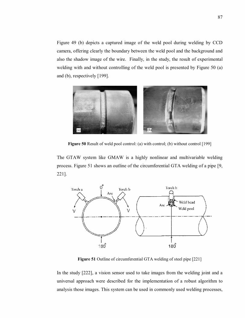
87
Figure 49 (b) depicts a captured image of the weld pool during welding by CCD
camera, offering clearly the boundary between the weld pool and the background and
also the shadow image of the wire. Finally, in the study, the result of experimental
welding with and without controlling of the weld pool is presented by Figure 50 (a)
and (b), respectively [199].
Figure 50 Result of weld pool control: (a) with control; (b) without control [199]
The GTAW system like GMAW is a highly nonlinear and multivariable welding
process. Figure 51 shows an outline of the circumferential GTA welding of a pipe [9,
221].
Figure 51 Outline of circumferential GTA welding of steel pipe [221]
In the study [222], a vision sensor used to take images from the welding joint and a
universal approach were described for the implementation of a robust algorithm to
analysis those images. This system can be used in commonly used welding processes,
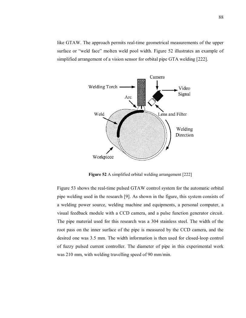
88
like GTAW. The approach permits real-time geometrical measurements of the upper
surface or “weld face” molten weld pool width. Figure 52 illustrates an example of
simplified arrangement of a vision sensor for orbital pipe GTA welding [222].
Figure 52 A simplified orbital welding arrangement [222]
Figure 53 shows the real-time pulsed GTAW control system for the automatic orbital
pipe welding used in the research [9]. As shown in the figure, this system consists of
a welding power source, welding machine and equipments, a personal computer, a
visual feedback module with a CCD camera, and a pulse function generator circuit.
The pipe material used for this research was a 304 stainless steel. The width of the
root pass on the inner surface of the pipe is measured by the CCD camera, and the
desired one was 3.5 mm. The width information is then used for closed-loop control
of fuzzy pulsed current controller. The diameter of pipe in this experimental work
was 210 mm, with welding travelling speed of 90 mm/min.
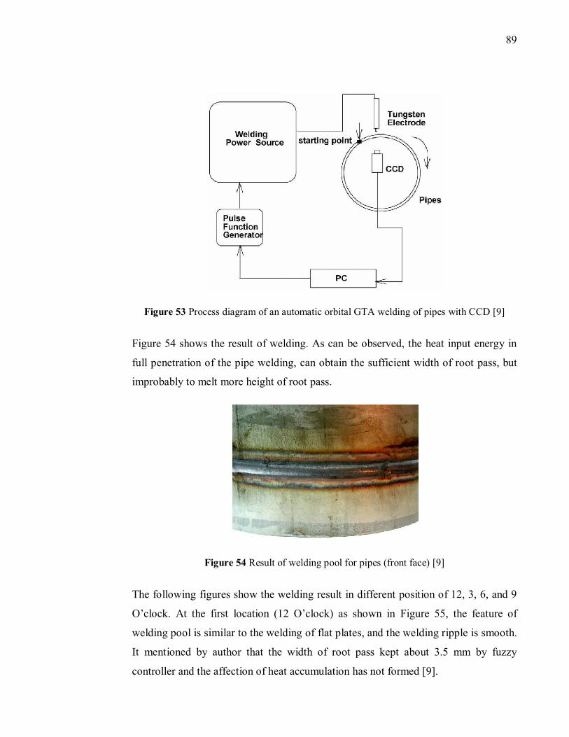
89
Figure 53 Process diagram of an automatic orbital GTA welding of pipes with CCD [9]
Figure 54 shows the result of welding. As can be observed, the heat input energy in
full penetration of the pipe welding, can obtain the sufficient width of root pass, but
improbably to melt more height of root pass.
Figure 54 Result of welding pool for pipes (front face) [9]
The following figures show the welding result in different position of 12, 3, 6, and 9
O’clock. At the first location (12 O’clock) as shown in Figure 55, the feature of
welding pool is similar to the welding of flat plates, and the welding ripple is smooth.
It mentioned by author that the width of root pass kept about 3.5 mm by fuzzy
controller and the affection of heat accumulation has not formed [9].
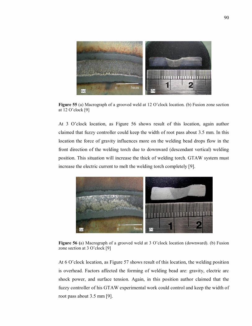
90
Figure 55 (a) Macrograph of a grooved weld at 12 O’clock location. (b) Fusion zone section at 12 O’clock [9]
At 3 O’clock location, as Figure 56 shows result of this location, again author
claimed that fuzzy controller could keep the width of root pass about 3.5 mm. In this
location the force of gravity influences more on the welding bead drops flow in the
front direction of the welding torch due to downward (descendant vertical) welding
position. This situation will increase the thick of welding torch. GTAW system must
increase the electric current to melt the welding torch completely [9].
Figure 56 (a) Macrograph of a grooved weld at 3 O’clock location (downward). (b) Fusion zone section at 3 O’clock [9]
At 6 O’clock location, as Figure 57 shows result of this location, the welding position
is overhead. Factors affected the forming of welding bead are: gravity, electric arc
shock power, and surface tension. Again, in this position author claimed that the
fuzzy controller of his GTAW experimental work could control and keep the width of
root pass about 3.5 mm [9].
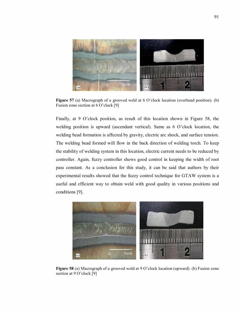
91
Figure 57 (a) Macrograph of a grooved weld at 6 O’clock location (overhead position). (b) Fusion zone section at 6 O’clock [9]
Finally, at 9 O’clock position, as result of this location shown in Figure 58, the
welding position is upward (ascendant vertical). Same as 6 O’clock location, the
welding bead formation is affected by gravity, electric arc shock, and surface tension.
The welding bead formed will flow in the back direction of welding torch. To keep
the stability of welding system in this location, electric current needs to be reduced by
controller. Again, fuzzy controller shows good control in keeping the width of root
pass constant. As a conclusion for this study, it can be said that authors by their
experimental results showed that the fuzzy control technique for GTAW system is a
useful and efficient way to obtain weld with good quality in various positions and
conditions [9].
Figure 58 (a) Macrograph of a grooved weld at 9 O’clock location (upward). (b) Fusion zone section at 9 O’clock [9]
92
7. Weld Quality Test and Control
Higher weld quality is obtained with modern orbital welding system compared to the
manual welding. The reason is that, the equipment of orbital system is designed for
real-time monitoring of the affecting weld parameters [223]. To have an ideal
welding result with orbital welding system, all the equipments and operators should
be certified. Also, each weld should be tested and certified to the desired standard
level [51]. In pipe welding, the following factors affect the welding joints result and
should be considered [128]:
Tube material, dimensions, and welding consumables
Machines, equipment, appliances, tools
Work preparation, welding parameter
Pipe welder, working conditions, supervision
Climate and environmental conditions
Knowledge, experience
For quality test [128]:
Inspection, examination of the surface
Test welds (destructive testing)
Ultrasonic examination and radiation tests
Pressure tests with water or air
After or during welding procedure, there are possibilities of some defects on the weld,
such as intergranular stress corrosion cracking, brittle fracture [15, 34]. One of the
significant defects in pipe welding is deformation and residual stresses in welded
structures due to a non-uniform temperature field. This non-uniformity of the pipe
section is called ‘‘ovality’’ and is shown in Figure 59 [10].
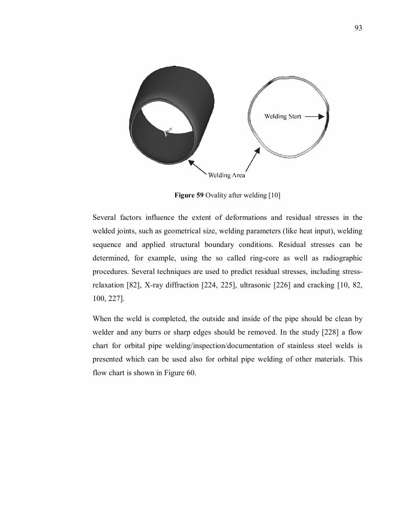
93
Figure 59 Ovality after welding [10]
Several factors influence the extent of deformations and residual stresses in the
welded joints, such as geometrical size, welding parameters (like heat input), welding
sequence and applied structural boundary conditions. Residual stresses can be
determined, for example, using the so called ring-core as well as radiographic
procedures. Several techniques are used to predict residual stresses, including stress-
relaxation [82], X-ray diffraction [224, 225], ultrasonic [226] and cracking [10, 82,
100, 227].
When the weld is completed, the outside and inside of the pipe should be clean by
welder and any burrs or sharp edges should be removed. In the study [228] a flow
chart for orbital pipe welding/inspection/documentation of stainless steel welds is
presented which can be used also for orbital pipe welding of other materials. This
flow chart is shown in Figure 60.
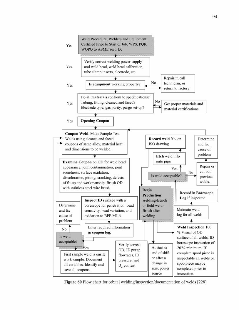
94
Figure 60 Flow chart for orbital welding/inspection/documentation of welds [228]
Weld Procedure, Welders and Equipment
Certified Prior to Start of Job. WPS, PQR,
WOPQ to ASME sect. IX
Verify correct welding power supply
and weld head, weld head calibration,
tube clamp inserts, electrode, etc.
Is equipment working properly?
Do all materials conform to specifications?
Tubing, fitting, cleaned and faced?
Electrode type, gas purity, purge set-up?
Repair it, call
technician, or
return to factory
Get proper materials and
material certifications.
Opening Coupon
Coupon Weld. Make Sample Test
Welds using cleaned and faced
coupons of same alloy, material heat
and dimensions to be welded.
Examine Coupon on OD for weld bead
appearance, joint contamination, joint
soundness, surface oxidation,
discoloration, pitting, cracking, defects
of fit-up and workmanship. Brush OD
with stainless steel wire brush.
Inspect ID surface with a
borescope for penetration, bead
concavity, bead variation, and
oxidation to BPE MJ-6.
Determine
and fix
cause of
problem
Enter required information
in coupon log. Is weld
acceptable?
First sample weld is onsite
work sample. Document
all variables. Identify and
save all coupons.
Record weld No. on
ISO drawing
Determine
and fix
cause of
problem
Is weld acceptable?
Etch weld info
onto pipe
Repair or
cut out
previous
welds.
Record in Borescope
Log if inspected
Maintain weld
log for all welds
Begin
Production
welding-Bench
or field weld-
Brush after
welding
Verify correct
OD, ID purge
flowrates, ID
pressure, and
O� content
At start or
end of shift
or after a
change in
size, power
source
Weld Inspection 100
% Visual of OD
surface of all welds. ID
borescope inspection of
20 % minimum. If
complete spool piece is
inspectable all welds on
spoolpiece maybe
completed prior to
inspection.
Yes
Yes
Yes
Yes
Yes
No
No
No Yes
Yes
No
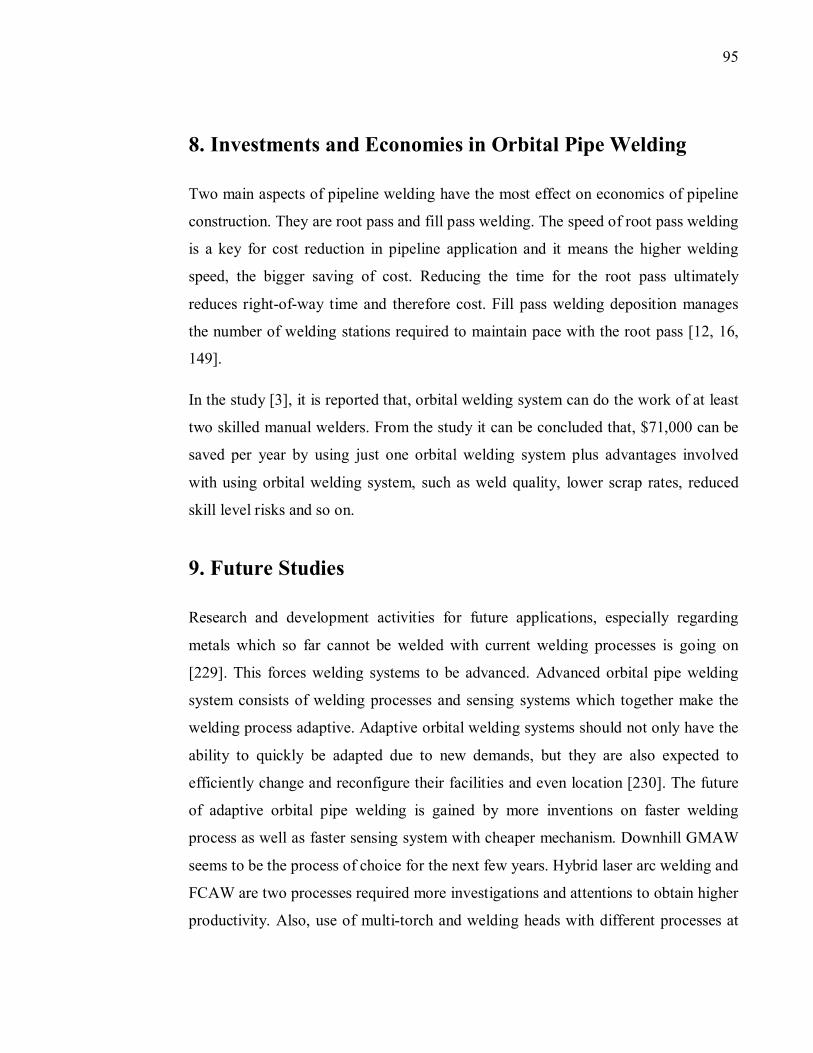
95
8. Investments and Economies in Orbital Pipe Welding
Two main aspects of pipeline welding have the most effect on economics of pipeline
construction. They are root pass and fill pass welding. The speed of root pass welding
is a key for cost reduction in pipeline application and it means the higher welding
speed, the bigger saving of cost. Reducing the time for the root pass ultimately
reduces right-of-way time and therefore cost. Fill pass welding deposition manages
the number of welding stations required to maintain pace with the root pass [12, 16,
149].
In the study [3], it is reported that, orbital welding system can do the work of at least
two skilled manual welders. From the study it can be concluded that, $71,000 can be
saved per year by using just one orbital welding system plus advantages involved
with using orbital welding system, such as weld quality, lower scrap rates, reduced
skill level risks and so on.
9. Future Studies
Research and development activities for future applications, especially regarding
metals which so far cannot be welded with current welding processes is going on
[229]. This forces welding systems to be advanced. Advanced orbital pipe welding
system consists of welding processes and sensing systems which together make the
welding process adaptive. Adaptive orbital welding systems should not only have the
ability to quickly be adapted due to new demands, but they are also expected to
efficiently change and reconfigure their facilities and even location [230]. The future
of adaptive orbital pipe welding is gained by more inventions on faster welding
process as well as faster sensing system with cheaper mechanism. Downhill GMAW
seems to be the process of choice for the next few years. Hybrid laser arc welding and
FCAW are two processes required more investigations and attentions to obtain higher
productivity. Also, use of multi-torch and welding heads with different processes at
96
the same time can reduce the welding cycle time and consequently, more economical
benefits will be obtained.
10. Summary and Conclusions
Stationary and orbital pipe welding were mentioned in this research work as two
main mechanized welding systems in pipe welding applications. In the stationary pipe
welding system, welding head has a fixed position while the pipe rotates. Various
processes, such as GMAW, SAW and GTAW can be used in stationary pipe welding.
SAW was mentioned as one of the main processes used for pipe welding in different
applications, such as pressure vessels, marine vessels, pipelines and offshore
structures. Using of T-SAW by twin arc mode or multi-wire was referred as a method
becoming more popular in longitudinal seam pipe production which leads to higher
proficiency.
In orbital pipe welding method, the welding head rotates around a fixed vertical or
horizontal pipe. Orbital pipe welding technique could yield in significant reductions
in the processing time, skilled welder, and welding costs but improvements in the
joint quality. Other advantages involved with this method of welding mentioned in
this report are, portability, accessibility, high speed, precision, and cost effectiveness.
Two types of orbital welding systems were explained in this study: closed head and
open head orbital welding systems. For welding of tubes, mostly closed head
machines are used and in the case of pipe welding with large diameters open head
machines are used. There are standard sizes of closed head welding system between
1.6 to 203 mm. Arc length during welding with this system remains fixed and the
process needs feeding of wire but controlling of arc voltage is not required. In
welding of stainless steels with this system, it should be considered that inside surface
of the pipe as well as outside should be protected from oxygen during whole process.
Generally, open head systems are used for pipe welding with large diameters and wall
thicknesses. Due to the complexity of this welding process, precise controlling of all
parameters in welding head requires a state-of-the-art computer.
97
Properties of pipe used in orbital welding were explained especially in oil and gas
applications. It noticed that, the majority of welded steel pipe is produced from coil or
plate. Numerous pipe materials can be welded by using orbital pipe welding system,
such as 300-series stainless steels (with the exception of the types 303 which contain
high sulfur and 303SE which contain selenium), 400-series stainless steels, high
strength low alloy steels, titanium and its alloys.
In crude oil transferring, there always has been possibility of corrosion in inner
surface of pipe. Crude oil consists of a heterogeneous mixture of hydrocarbons with
non-hydrocarbon components which includes alcohols, phenols, sediments, water,
salts, sulfur compounds, acid gases, and carbon monoxide. Therefore, high level of
safety and trust direct to reduction of cost, highest efficiency, and lowest defects,
required in oil and gas pipeline distribution.
On the other hand, increscent demand of oil and gas leads to the requirement of high
pressure pipelines. Higher pressures and flow levels, therefore towards using line pipe
of larger diameter and/or special material. Therefore, pipes with higher level strength
have been produced during ages, such as X70, X80, X100, and X120.
X70 is micro-alloyed steel consists of niobium and vanadium with lower amount of
carbon. X80 steel is purer and consists of lower sulfur compared with X70 steel and
can be adapted to different welding heat inputs. X80 steel were invented by
combining Thermo-mechanical rolling and subsequent accelerated cooling. This leads
to higher strength, lower Carbon content and as a result better field weldability rather
X70 steel. X100 steel produced by adding molybdenum, copper, and nickel and is
processed to plate by combining Thermo-mechanical rolling and modified accelerated
cooling. The X120 steel, with yield strength of 827.4 MPa is 50 % stronger than
standard gas transmission pipe. It means more and higher gas pressure can be
transferred but requiring special welding procedure is its problem.
GTAW and SMAW are still using in root pass welding and
semiautomatic/mechanized GMAW and orbital GMAW are added to those processes.
98
In the welding of root pass with mechanized GMAW system, there is no possibility
of using flux cored wire due to the potential for slag entrapment.
Fill pass welding is done after root pass and takes most part of the welding time. Fill
pass welding is usually consisted of number of layers and several passes included to
each layers. Each pass positioning should be precise and relative to the current state
of the weld joint. This requires the sensor to analysis the image of filled joint,
especially the points on the joint sidewall where the previous passes are located.
Generally, in mechanized pipe welding, types of groove used in pressure vessels are
traditional V, butt, narrow or semi-narrow gap, and fillet profiles. In heavy industrial
applications, U and fillet groove are used. In automatic welding of smaller pipes and
tubes, a standard V-bevel with a small gap can be used, although J-prep with the pipe
ends butted together is the most popular groove types for this welding procedure.
Also, girth-butt welds of pipes have been used widely in various applications, such as
oil and gas pipelines, steam piping, boiling water reactor piping systems, etc.
It noted that, possible gap in orbital welding is 10 % of wall thickness but this
number is risky and gap less than 5 % is preferred. Wall thickness variation has the
same story which it can be 25 % of wall thickness but to minimize the risk of weak
weld quality and repeatability this number is mentioned ±5 % of nominal wall
thickness.
In this master’s thesis, adaptive welding were explained as, finding the center of the
joint (dynamic joint tracking) and also, automatic controlling of the weld power, wire
feed, rotation (travel speed), pulse time, oscillation width, torch motion and position,
etc. This helps simplify operation and produce a high quality weld. It can be done by,
weld pool geometry sensing, modeling and intelligent control of the weld quality and
process monitoring. Today, multi laser vision sensors, thermal scanning, image
processing, neural network model, machine vision, or optical sensing are used in
various fully automatic orbital welding system to improve performance and
reliability. Adaptive control of the orbital welding process must be performed during
the fill pass and not root pass welding.
99
The most used welding processes for orbital pipe welding (GTAW, FCAW, GMAW,
and HLAW) were explained in this study and as conclusion it can be mentioned that:
GTAW, STT, short circuit, modified short arc GMAW are the most useful processes
used in welding of root pass. Mainly, for fill pass welding mostly GMAW method is
used.
Orbital GTAW process mostly is applied for applications ranging from single run
welding of thin walled stainless pipes to multi run welding of thick walled pipes.
Even welding of narrow-gap can be done due to its precise control of heat input,
repeatability of welding procedures, ability of equipment for using “on site”, higher
operator productivity and duty cycle, consistent weld quality and so on. Argon is the
most commonly used shield gas in GTAW process. In welding of stainless steels,
nickel copper and nickel based alloys mixture of argon/helium typically used.
Mixtures of 95 % argon and 5 % hydrogen are incompatible with carbon steels and
some exotic alloys and can cause hydrogen embrittlement in the weld. In orbital
GTAW systems, the most typical used tungsten electrode materials are 2 % thoriated
tungsten and 2 % ceriated tungsten.
FCAW was invented to eliminate long time consumption due to the low speed of
GTAW process on pipe welding. Also, FCAW compensates the greater volume of
weld metal by higher deposition rate on the standard bevel. Automated FCAW is
faster process compared to SMAW and can meet the same quality standards as
SMAW, SAW, and in most cases, GTAW.
DT-GMAW technique is currently considered the most efficient method in welding
of fill and cap passes. Modified short circuit GMAW process is a special design for
the root pass welding (80.3 mm or greater) and can be replaced to the GTAW in
many applications. Also, STT process were mentioned three or four times faster than
GTAW to complete open root welds in pipe welding applications with better back
beads and edge fusion without use of ceramic or copper internal back up bars.
CO� lasers are not suitable power source for orbital HLA Welding of pipe due to
difficulty of transferring laser beam to the workpiece. On the other hand, high power
100
Nd:YAG has the possibility of transferring by optical fiber and using in orbital
welding of land pipeline applications. Furthermore, diode lasers can be used in
pipeline applications. Fiber lasers were claimed to improve pipe welding speed 50 %
faster.
Nd:YAG laser power combined with GMAW process has been recently used in
welding of 5G position and for girth welding of land pipelines for the oil and gas
industry with an acceptable geometric profile of weld bead.
To ensure the quality of weld, precise control of torch angle in the displacement plane
during welding process, and precise control of torch position to be in the center of
groove are required. In this study, different studies have been done in these cases
were reviewed and explained. Laser vision sensor for seam tracking during orbital
welding is preferred methods in pipe welding industry especially in noisy
environments.
Orbital welding system can carry out the work of at least two skilled manual welders
in root and fill pass welding with higher quality and less defects. Also, with orbital
system, speed of root pass welding is higher than manual welding and this is the key
for cost reduction in pipeline application.
The improvement of orbital welding systems reach to the level that the invention of
new welding machine and technology for pipeline applications is risky for
constructor. On the other hand, improvement of pipe materials with lower cost, such
as X80, X100, and X120 will continue in the future and this forces constructors for
using new welding processes and machines. They will have an important part to play
in the continuing improvement of the economics of pipeline welding.
101
References
[1] J. Emmerson, "Multipass orbital welding of pipe," The Tube & Pipe Journal,
vol. 10, no. 1, pp. 22-26, 1999.
[2] J. A. O. Garcia., G. L. Lima., W. D. B. Pereira., V. A. Guimarães., C. Moura
Neto., R. P. R. Paranhos, "Characterization of titanium welded joints by the
orbital gas tungsten arc welding process for aerospace application," Journal of
Aerospace Technology and Management., São José dos Campos, vol. 2, no. 2,
pp. 211-218, 2010.
[3] B. Mannion, "The fundamentals of orbital welding," Gases & Welding
Distributor, vol. 44, no. 1, pp. 42-44, 2000.
[4] B. Mannion., J. Heinzman, "Setting up and determining parameters for orbital
tube welding," The Fabricator, vol. 29, pp. 26-30, 1999.
[5] E. A. Benway, "Advancements in automatic orbital welding expand its use,
provide welders with more option," Industrial Maintenance & Plant Operation,
vol. 61, no. 7, p. 22, 2000.
[6] H. Günther, "Gegenwartige stand des maschinellen zwangslagenschweisens
von rohrrundnahten auf der baustelle," Schweissen und Schneiden, vol. 14, no.
10, pp. 2-8, 1962.
[7] D. J. Widgery, "Mechanised welding of pipelines," The ESAB Welding and
Cutting Journal, Svetsaren, vol. 60, no. 1, pp. 23-26, 2005.
[8] P. Sagues, "Adaptive control techniques advance automatic welding," Welding
Journal, vol. 89, no. 8, pp. 26-28, 2010.
[9] C. H. Tsai., K. H. Houb., H. T. Chuang, "Fuzzy control of pulsed GTA welds
by using real-time root bead image feedback," Journal of Materials Processing
102
Technolog, vol. 176, no. 1-3, pp. 158-167, 2006.
[10] I. Sattari-Far., Y. Javadi, "Influence of welding sequence on welding distortions
in pipes," International Journal of Pressure Vessels and Piping, vol. 85, no. 4,
pp. 265-274, 2008.
[11] M. Bishop, "Welding more with less, new technologies take a comprehensive
approach to orbital welding operations," The Fabricator, An FMA Publication,
2002.
[12] I. D. Harris, "Welding advances in tube and pipe applications," Welding
Journal, vol. 90, no. 6, pp. 58-63, 2011.
[13] J. Glessman, "Automated orbital welding systems streamline in-process
inspections," Plant Engineering, vol. 65, no. 8, pp. 39-42, 2011.
[14] J. M. Brzezicki, "Orbital welding offers microprocessor control and high
quality," Gases & Welding Distributor, vol. 46, no. 3, pp. 25-28, 2002.
[15] T. L. Tenga., P. H. Chang, "Three-dimensional thermomechanical analysis of
circumferentially welded thin-walled pipes," International Journal of Pressure
Vessels and Piping, vol. 75, no. 3, pp. 237-247, 1998.
[16] D. Yapp., S. A. Blackman, "Recent developments in high productivity pipeline
welding," Journal of the Brazilian Society of Mechanical Sciences and
Engineering, vol. 26, no. 1, pp. 89-97, 2004.
[17] K. Faes., A. Dhooge., P. Baets., E. V. D. Donckt., W. Waele, "Parameter
optimization for automatic pipeline girth welding using a new friction welding
method," Materials and Design, vol. 30, no. 3, pp. 581-589, 2009.
[18] E. K. Stava., P. Nicholson, "New technology speeds oil sands pipe welding,"
Pipeline & Gas Journal, vol. 228, no. 12, pp. 37-39, 2001.
103
[19] E. K. Stava., P. Nicholson, "Automation improves pipeline welding," Welding
Design & Fabrication, vol. 74, no. 11, pp. 19-23, 2001.
[20] A. S. Baskoro., R. Masuda., M. Kabutomori., Y. Suga, "An application of
genetic algorithm for edge detection of molten pool in fixed pipe welding,"
International Journal of Advanced Manufacturing Technology, vol. 45, no. 11,
pp. 1104-1112, 2009.
[21] D. J. Widgery, "Welding high strength pipelines: from laboratory to field," The
ESAB Welding and Cutting Journal, Svetsaren, vol. 75, no. 2, pp. 22-25, 2002.
[22] J. Lukkari, "Orbital TIG – A great way to join pipes," The ESAB Welding and
Cutting Journal, Svetsaren, vol. 60, no. 1, pp. 3-6, 2005.
[23] H. Latifi, Factory visit, Bushehr: Iranian Marine Industry, 2012.
[24] B. K. Henon., A. Brond., H. Mosciaro, "Orbital welding best competition,"
Welding Design & Fabrication, vol. 75, no. 8, pp. 28-54, 2002.
[25] S. Kou, Welding metallurgy, 2nd ed, john Wiley & Sons, 2003.
[26] w. Robert., J. R. Messler, Principles of welding, processes, physics, chemistry,
and metallurgy, Weinheim: WILEY-VCH Verlag GmbH & Co. KGaA, 2004.
[27] P. T. H. croft, Submerged arc welding, 2nd ed, Cambridge: Abington
Publishing, 1989.
[28] V. Gunaraja., N. Murugan, "Prediction and comparison of the area of the heat-
affected zone for the bead-on-plate and bead-on-joint in submerged arc welding
of pipes," Journal of Materials Processing Technology, vol. 95, no. 3, pp. 246-
261, 1999.
[29] H. S. Moon., R. J. Beattie, A fully automatic adaptive pressure Vessel welding
104
system, Chicago: American Welding Society (AWS), 2002.
[30] H. S. Moon., Y. B. Kim., R. J. Beattie, "Multi sensor data fusion for improving
performance and reliability of fully automatic welding system," The
International Journal of Advanced Manufacturing Technology, vol. 28, no. 3-4,
pp. 286-293, 2006.
[31] V. Gunaraj., N. Murugan, "Application of response surface methodology for
predicting weld bead quality in submerged arc welding of pipes," Journal of
Materials Processing Technology, vol. 88, no. 1-3, pp. 266-275, 1999.
[32] N. Murugan., V. Gunaraj, "Prediction and control of weld bead geometry and
shape relationships in submerged arc welding of pipes," Journal of Materials
Processing Technology, vol. 168, no. 3, pp. 478-487, 2005.
[33] J. G. Emmerson, "FCAW orbital pipe welding technology Improves fab shop
productivity," Welding Journal, vol. 78, no. 11, pp. 57-60, 1999.
[34] S. Moeinifar., A. H. Kokabi., H. R. Madaah Hosseini, "Role of tandem
submerged arc welding thermal cycles on properties of the heat affected zone in
X80 microalloyed pipe line steel," Journal of Materials Processing
Technology, vol. 211, no. 3, pp. 368-375, 2011.
[35] J. E. Hinkel., F. W. Forsthoefel, "High current density submerged arc welding
with twin wires," Welding Journal, vol. 55, no. 3, pp. 175-180, 1976.
[36] R. S. Chandel, "Deposition characteristics of twin wire submerged," in
Proceedings International Conference on Offshore Materials and Arctic
Engineering, Houston, 1990.
[37] Z. Huang., M. Kai., J. Liu., J. Kong., Y. Wang, "Welding high strength line
pipe," Pipeline & Gas Technology, vol. 2008, no. 10, pp. 30-34, 2008.
105
[38] I. I. Ivochkin., Steklov, "Prospect for the use of powdered filler metal in fusion
welding," Welding Production, vol. 6, pp. 22-27, 1969.
[39] N. baily, "Submerged arc welding ferritic steels with alloyed metal," Welding
Journal, vol. 70, no. 8, pp. 187-206, 1991.
[40] R. S. Chandel., H. P. Seow., F. L. Cheong, "Effect of increasing deposition rate
on the bead geometry of submerged arc welds," Journal of Materials
Processing Technology, vol. 72, no. 1, pp. 124-128, 1997.
[41] R. L. Apps., L. M. Gourd., K. A. Nelson, "Effect of welding variables upon
bead shape and size in submerged arc welding," Welding Metal Fabrication,
vol. 31, no. 11, p. 453, 1963.
[42] J. Doherty., G. R. Salter, "Development in procedure selection techniques,"
Welding Institute Research Bulletin, vol. 18, no. 6, 1977.
[43] J. C. McGlone, Aninvestigation into the effect of joint angle on bead geometry
for the submerged arc welding of mild steel, Welding Institute, 1977.
[44] L. J. Yang., M. J. Bibby., R. S. Chandel, "Modeling the submerged arc welding
process using linear regression analysis," in 3rd Conference, Trends in Welding
Research, Gatlinburg, 1992.
[45] R. Wilsdorf., R. Pistor., J. J. Sixsmith., H. Jin, "Welding aluminum pipe and
tube with variable polarity," Welding Journal, vol. 85, no. 4, pp. 42-43, 2006.
[46] "Automation," Welding Design & Fabrication, vol. 76, no. 12, pp. 22-25, 2003.
[47] J. Emmerson, "Orbital narrow gap MCW pipe welding," Welding & Metal
Fabrication, vol. 68, no. 8, pp. 9-11, 2000.
[48] E. A. Benway, "What to look for in orbital welding training programs,"
106
Penton's Welding Magazine, vol. 82, no. 5, pp. 18-22, 2009.
[49] K. Faes., A. Dhooge., P. D. Baets., P. Afschrift, "New friction welding process
for pipeline girth welds-welding time optimization," The International Journal
of Advances Manufacturing Technology, vol. 43, no. 9-10, pp. 982-992, 2009.
[50] L. Brioux, "Kentucky power plant turns to orbital pipe welding for expansion,"
Welding Journal, vol. 89, no. 6, pp. 58-59, 2010.
[51] S. Purnell, "How to achieve a clean process line in stainless steel pipes," World
Pumps, vol. 2003, no. 447, pp. 17-18, 20-21, 2003.
[52] H. Latifi, Factory visit, Mazandaran: Gaam Electric, 2012.
[53] J. Emmerson, "Considering GMAW/FCAW for orbital applications tips for the
prospective first-time user," Magnatech, March/April 2000. [Online].
Available: http://www.magnatechllc.com. [Accessed 25 March 2012].
[54] S. A. Blackman., D. V. Dorling., R. Howard, "High-speed tandem GMAW for
pipeline welding," in International Pipeline Conference, Calgary, 2003.
[55] Y.-i. Komizo, "Overview of recent welding technology relating to pipeline
construction," Transactions of Joining and Welding Research Institute (JWRI),
vol. 37, no. 1, pp. 1-5, 2008.
[56] R. Paschold., D. Dirksen, "Submerged arc welding of steels for offshore wind
towers," The ESAB Welding and Cutting Journal, Svetsaren, vol. 60, no. 1, pp.
13-17, 2005.
[57] K. Pal., S. K. Pal, "Effect of pulse parameters on weld quality in pulsed gas
metal arc welding: A review," Journal of Materials Engineering and
Performance, vol. 20, no. 6, pp. 918-931, 2011.
107
[58] A. Kumar., M. Sapp., J. Vincelli., M. C. Gupta, "A study on laser cleaning and
pulsed gas tungsten arc welding of Ti–3Al–2.5V alloy tubes," Journal of
Materials Processing Technology, vol. 210, no. 1, pp. 64-71, 2010.
[59] B. K. Henon, "Orbital welding of titanium pipe for U.S. navy ships," Welding
Journal, vol. 88, no. 9, pp. 26-28, 2009.
[60] T. Maretta, "Multiple-wire welding improves productivity and quality at pipe
mill," Pipeline & Gas Journal, vol. 229, no. 4, pp. 70-74, 2002.
[61] J. R. Still, "Weld metal properties of reeled pipelines," Welding Journal, vol.
83, no. 7, pp. 42-47, 2004.
[62] K. Y. Lee, "Pipeline weld discontinuities too small to matter," Welding Journal,
vol. 87, no. 4, pp. 34-35, 2008.
[63] D. Howse., R. Scudamore., A. Woloszyn,. G. Booth., R. Howard,
"Development of the laser/MAG hybrid welding process for land pipeline
construction," in International Conference on the Application and Evaluation
of High-Grade Linepipes in Hostile Environments, Yokahama, 2002.
[64] H. S. Moon., R. J. Beattie, "Development of adaptive fill control for multitorch
multipass submerged arc welding," The International Journal of Advanced
Manufacturing Technology, vol. 19, no. 12, pp. 867-872, 2002.
[65] C. R. F. Azevedo, "Failure analysis of a crude oil pipeline," Engineering
Failure Analysis, vol. 14, no. 6, pp. 978-994, 2007.
[66] S. G. Polyakov., L. I. Nyrkova., S. L. Melnichuk., N. A. Gapula, "Diagnostics
of corrosion state of inner surface of main oil pipeline," The Paton Welding
Journal, vol. 2010, no. 12, pp. 18-21, 2010.
[67] J. B. Ju., J. S. Lee., J. I. Jan, "Fracture toughness anisotropy in a API steel line-
108
pipe," Materials Letters, vol. 61, no. 29, pp. 5178-5180, 2007.
[68] F. R. Xiao., B. Liao., Y. Y. Shan., G. Y. Qiao., Y. Zhong., C. Zhang., K. Yang,
"Challenge of mechanical properties of an acicular ferrite pipeline steel,"
Materials Science and Engineering: A, vol. 431, no. 1-2, pp. 41-52, 2006.
[69] S. Y. Shin., B. Hwang., S. Lee., N. J Kim., S. S. Ahn, "Correlation of
microstructure and charpy impact properties in API X70 and X80 line-pipe
steels," Materials Science and Engineering: A, vol. 485, no. 1-2, pp. 281-289,
2007.
[70] T. Pan., Z. G. Yang., C. Zhang., B. Z. Bai., H. S. Fang, "Kinetic and
mechanisms of intragranular ferrite nucleation on non-metallic inclusions in
low carbon steels," Materials Science and Engineering: A, Vols. 438-440, pp.
1128-1132, 2006.
[71] S. Moeinifar., A. H. Kokabi., H. R. Madaah Hosseini, "Effect of tandem
submerged arc welding process and parameters of Gleeble simulator thermal
cycles on properties of the intercritically reheated heat affected zone,"
Materials & Design, vol. 32, no. 2, pp. 869-876, 2011.
[72] J. Hilkes., F. Neessen., S. Caballero, "Electrodes for welding, extremely low
service temperatures demand special materials and processes," Welding
Journal, vol. 83, no. 1, pp. 30-37, 2004.
[73] H. G. Hillenbrand., A. Liessem., C. Kalwa., M. Erdelen-Peppler., C.
Stallybrass, "Technological solutions for high strength gas pipelines," in
Proceedings of International Pipeline Steel Forum, Peking, 2008.
[74] D. Qingquan., Z. Hong., Y. Feng., D. Changyi, "Hydrostatic burst test 0F X80
grade steel pipe," Journal of Loss Prevention in the Process Industries, vol. 22,
no. 6, pp. 897-900, 2009.
109
[75] S. Gook., A. Gumenyuk., M. Lammers., M. Rethmeier, "Peculiarities of the
process of orbital laser-arc welding of thick-walled large-diameter pipes," The
Paton Welding Journal, vol. 2010, no. 9, pp. 2-8, 2010.
[76] R. Hancock, "Welding the world’s strongest linepipe in Arctic conditions,"
Welding Journal, vol. 83, no. 7, pp. 58-59, 2004.
[77] E. K. Stava, "Waveform control speeds root pass," Welding Design &
Fabrication, vol. 74, no. 2, pp. 39-41, 2001.
[78] A. M. Torbati., R. M. Miranda., L. Quintino., S. Williams., D. Yapp,
"Optimization procedures for GMAW of bimetal pipes," Journal of Materials
Processing Technology, vol. 211, no. 6, pp. 1112-1116, 2011.
[79] N. Sonsuvit., S. Chandra-ambhorn, Effects of TIG pulse welding parameters
and nitrogen gas mixed in argon shielding gas on weld bead formation and
microstructure of weld metals of AISI 304L stainless steels at the 10-h welding
position, Dallas: American Welding Society (AWS), 2005.
[80] V. Carucci., A. Fulcini, "The mechanised MAG welding of the Clare natural
gas line," The ESAB Welding and Cutting Journal, Svetsaren, vol. 57, no. 2, pp.
36-38, 2002.
[81] G. Garcia, "Mechanized pipeline welding in the Saudi desert," The ESAB
Welding and Cutting Journal, Svetsaren, vol. 63, no. 1, pp. 37-40, 2008.
[82] T. L. Teng., P. H. Chang, "A study of residual stresses in multi-pass girth-butt
welded pipes," International Journal of Pressure Vessels and Piping, vol. 74,
no. 1, pp. 59-70, 1997.
[83] J. Böhm., G. Engelhard., D. Pellkofer, "Erzeugung von druckspannungen zur
vermeidung von spannungsrißkorrosion mit hilfe des WIG-orbitalschweißens,"
in Welding Conference, Hannover, 1996.
110
[84] G. Engelhard., L. M. Habip., D. Pellkofer., J. Schmidt., J. Weber,
"Optimization of residual welding stresses in austenitic steel piping proof
testing and numerical simulation of welding and post welding processes,"
Nuclear Engineering and Design, vol. 198, no. 1-2, pp. 141-151, 2000.
[85] J. Glessman, "Orbital welding systems streamline in-process inspections,"
Welding Journal, vol. 90, no. 6, pp. 64-66, 2011.
[86] R. A. Harris, "Inverter power source makes tough job easier," Welding Design
& Fabrication, vol. 75, no. 11, pp. 27-30, 2002.
[87] D. C. Smith, "Flux-cored electrodes — Their composition and use," Welding
Journal, vol. 49, no. 7, pp. 535-547, 1970.
[88] E. Baune., C. Bonnet., S. Liu, "Reconsidering the basicity of a FCAW
consumable — Part 1: solidified slag composition of a FCAW consumable as a
basicity indicator," Welding Journal, vol. 79, no. 3, pp. 57-65, 2000.
[89] Consumables for manual and automatic welding, 8th ed, ESAB Welding
Handbook, 2005.
[90] E. M. Westin., D Garrett, "Welded stainless steel tubes & pipes vs. seamless,"
in 10th Brazilian Stainless Steel Conference, 2011.
[91] N. Wikström., T. Salmi, "Permanova’s seam tracking laser welding tool," The
ESAB Welding and Cutting Journal, Svetsaren, vol. 60, no. 1, pp. 18-20, 2005.
[92] H. B. Chen., T. Lin., S. B. Chen., J. F. Wang., J. Q. Jia., H. Zhang, "Adaptive
control on wire feeding in robot arc welding system," in Robotics, Automation
and Mechatronics, Chengdu, 2008.
[93] Y. S. Tarng., J. L. Wu., S. S. Yeh., et al., "Intelligent modeling and
optimization of the gas tungsten arc welding process," Journal of Intelligent
111
Manufacture, vol. 10, pp. 73-79, 1999.
[94] C. Shanben, et al., "On intelligentized technologies for modern welding
manufacturing," Chinese Journal of Mechanical Engineering, vol. 16, no. 4, pp.
367-370, 2003.
[95] R. J. Beatlie., S. K. Cheng., P. S. Logue, "The use of vision sensors in
multipass welding applications," Welding Journal, vol. 67, no. 11, pp. 28-33,
1988.
[96] Zh. Y. Zhu., T. Lin., Y. J. Piao., S. B. Chen, "Recognition of the initial position
of the weld based on the image pattern match technology," The International
Journal of Advanced Manufacturing Technology, vol. 26, pp. 784-788, 2005.
[97] J. W. Kim., S. J. Na, "A Self-organizing fuzzy control approach to arc sensor
for weld joint tracking in gas metal arc welding of butt joints," Welding
Journal, vol. 72, no. 1, pp. 60-66, 1993.
[98] Y. Suga., M. Naruse, "Application of neural network to visual sensing of weld
line and automatic tracking in robot welding," Welding in the World, vol. 34,
pp. 275-284, 1994.
[99] G. E. Cook., R. J. Barnett., K. Andersen., A. M Strauss, "Weld modeling and
control using artificial neural networks," IEEE Transactions on Industry
Applications, vol. 31, no. 6, pp. 1484-1491, 1995.
[100] C. Doumanidis., Y. M. Kwak, "Multivariable adaptive control of the bead
profile geometry in gas metal arc welding with thermal scanning," International
Journal of Pressure Vessels and Piping, vol. 79, no. 4, pp. 251-262, 2002.
[101] G. j. Zhang., Z. h. Yan, et al., "Visual sensing of weld pool in variable polarity
TIG welding of aluminum alloy," Transactions of Nonferrous Metals Society of
China, vol. 16, pp. 522-526, 2006.
112
[102] K. P. Valavanis., G. N. Saridis, "Intelligent robotics system: Theory, design and
applications," The Springer International Series in Engineering and Computer
Science, vol. 182, pp. 12-18, 1992.
[103] S. C. Juang., Y. S. Tarng, "Process parameter selection for optimizing the weld
pool geometry in the tungsten inert gas welding of stainless steel," Journal of
Materials processing Technology, vol. 122, no. 1, pp. 33-37, 2002.
[104] J. Cuhel, "GMAW options offer increased productivity for pipe fab shops,"
Welding Journal, vol. 87, no. 6, pp. 66-68, 2008.
[105] J. W. Jeong., I. S. Kim., W. S. Kim., Y. P. Kim., C. M. Kim., J. S. Kim., H. H.
Na., J. H. Choi, "A study on optimized technology for an automatic root-pass
welding of girth weldment in pipeline," American Institute of Physics, vol.
1315, no. 1, pp. 813-818, 2010.
[106] G. Zeng, "Plasma arc welding principle and application," Welding and Cutting,
vol. 9, no. 1, pp. 38-44, 1989.
[107] X. R. Li., Z. Shao., Y. M. Zhang, "Double stage plasma arc pipe welding
process," Welding Journal, vol. 91, pp. 346-353, 2012.
[108] J. S. Shih., Y. F. Tzeng., Y. F. Lin., J. B. Yang, "Multi-objective process
optimization of pulsed plasma arc welding SS400 steel pipe with foamed
aluminum liner," Journal of Advanced Mechanical Design, Systems, and
Manufacturing, vol. 6, no. 2, pp. 222-235, 2012.
[109] H. Cary, Modern welding technology, 2nd ed, American Welding Society
(AWS), 1981.
[110] N. Ahmed, New developments in advanced welding, Cambridge: Woodhead
Publishing Limited, 2005.
113
[111] J. Emmerson, "8 FAQs about orbibal FCAW: Maximizing a productivity tool
for large-pipe welding," The Fabricator, vol. 37, no. 8, pp. 34-37, 2007.
[112] J. Emmerson, "Using mechanized welding on large-diameter pipes," Welding
Journal, vol. 86, no. 6, p. 66, 2007.
[113] X. R. Li., J. Heusman., L. Kvidahl., P. Hoyt., Y. M. Zhang, "Manual keyhole
plasma arc welding with application," Welding Journal, vol. 90, no. 12, pp.
258-264, 2011.
[114] G. Lothongkum., E. Viyanit., P. Bhandhubanyong, "Study on the effects of
pulsed TIG welding parameters on delta-ferrite content, shape factor and bead
quality in orbital welding of AISI 316L stainless steel plate," Journal of
Materials Processing Technology, vol. 110, no. 2, pp. 233-238, 2001.
[115] G. Hicken, Gas-tungsten arc welding, ASM Handbook, 1993.
[116] A. D. Althouse., C. H. Turnquist., W. A. Bowditch., K. E. Bowditch, Gas
tungsten arc welding, modern welding, The Goodheart– Willcox Company Inc,
1992.
[117] P. J. Modenesi., E. R. Apolinário., I. M. Pereira, "TIG welding with single-
component fluxes," Journal of Materials Processing Technology, vol. 99, no. 1-
3, pp. 260-265, 2000.
[118] W. H. Minnick, Gas tungsten arc welding handbook, Tinley Park: The
Goodheart-Willcox Company, Inc., 1996.
[119] J. Tuseka., M. Suban, "Experimental research of the effect of hydrogen in argon
as a shielding gas in arc welding of high alloy stainless steel," International
Journal of Hydrogen Energy, vol. 25, no. 4, pp. 369-376, 2000.
[120] A. Durgutlu, "Experimental investigation of the effect of hydrogen in argon as
114
a shielding gas on TIG welding of austenitic stainless steel," Materials &
Design, vol. 25, no. 1, pp. 19-23, 2004.
[121] R. Morrow., J. Haidar., A. B. Murphy, "Prediction of gas tungsten arc welding
properties in mixtures of argon and hydrogen," IEEE Transactions on Plasma
Science, vol. 25, no. 5, pp. 925-930, 1997.
[122] J. Page., J. Emmerson, "Mechanized weld buildup repairs Coker," Welding
Journal, vol. 87, no. 6, pp. 42-64, 2008.
[123] T. Myers, "Choosing a shielding gas for FCAW," Welding Journal, vol. 89, no.
3, pp. 30-33, 2010.
[124] K. H. Li., J. S. Chen., Y. M. Zhang, "Double-electrode GMAW process and
control," Welding Journal, vol. 86, no. 8, pp. 231-237, 2007.
[125] V. Velmurugan., V. Gunuaraj, "Effects of process parameters on angular
distortion of gas metal arc welded structural steel plates," Welding Journal, vol.
84, no. 11, pp. 165-171, 2005.
[126] D. S. Naidu., S. Ozcelik., K. L. Moore, Modeling, sensing and control of gas
metal arc welding, UK: Elsevier Science Publishing Company, 2003.
[127] P. K. Palani., N. Murugan, "Development of mathematical models for
prediction of weld bead geometry in cladding by Flux Cored Arc," The
International Journal of Advanced Manufacturing Technology, vol. 30, no. 7-8,
pp. 669-676, 2006.
[128] E. Vietz., H. Kohn., C. Thomy., F. Vollertsen, "The VPL® fiber laser system -
an innovation in the welding technology for pipeline construction," in Pipeline
Technology Conference, Hannover, 2006.
[129] A. D. Tipi, "Neutralizing the effect of the angle variations on the drop
115
detachment in automatic GMAW system," The International Journal of
Advanced Manufacturing Technology, vol. 54, no. 1-4, pp. 123-137, 2011.
[130] A. D. Tipi, "The study on the drop detachment for automatic pipeline GMAW
system: free flight mode," The International Journal of Advance Manufacturing
Technology, vol. 50, no. 1-4, pp. 137-147, 2010.
[131] S. Laymon., C. Chritz., F. Schweighardt, "Argon/oxygen shielding gases
improve carbon steel GMAW," Welding Journal, vol. 89, no. 3, pp. 40-43,
2010.
[132] A. S. Shahi., S. Pandey., J. S. Gill, "Effect of auxiliary preheating of filler wire
on dilution in gas metal arc stainless steel surfacing using RSM," Surface
Engineering, vol. 23, no. 5, pp. 384-390, 2007.
[133] V. S. R. Murti., P. D. Srinivas., G. H. D. Banadeki., K. S. Raju, "Effect of heat
input on the metallurgical properties of HSLA steel in multi-pass MIG
welding," Journal of Materials Processing Technology, vol. 37, no. 1-4, pp.
723-729, 1993.
[134] Y. C. Lin., K. H. Lee, "Effect of preheating on the residual stress in type 304
stainless steel weldment," Journal of Materials Processing Technology, vol. 63,
no. 1-3, pp. 797-801, 1997.
[135] T. Mohandas., G. M. Reddy., B. S. Kumar, "Heat affected zone softening in
high-strength low-alloy steels," Journal of Materials Processing Technology,
vol. 88, no. 1, pp. 284-294, 1999.
[136] T. Nakamura., K. Hiraoka, "Ultranarrow GMAW process with newly
developed wire melting control system," Science and Technology of Welding &
Joining, vol. 6, no. 6, pp. 355-362, 2001.
[137] J. Church, "T.I.M.E. process produces fracture-proof welds," Welding Design
116
and Fabrication, vol. 74, no. 5, pp. 32-35, 2001.
[138] R. Lahnsteiner, "The T.I.M.E. process — an innovative MAG welding
process," Welding Review International, vol. 11, no. 1, pp. 17-20, 1992.
[139] K. X. Chen., H. Q. Li., C. X. Li, "Progress in variable polarity plasma arc
welding," Transactions of the China Welding Institution, vol. 25, no. 1, pp.
124-128, 2004.
[140] H. Cary., W. Chaisson, Variable polarity plasma arc welding, Metairie LA,
Washington: Aluminum Association, 1986.
[141] T. Ueyama., H. Tong., S. Harada., R. Passmore., M. Ushhio, "AC pulsed
GMAW improves sheet metal joining," Welding Journal, vol. 84, no. 2, pp. 40-
46, 2005.
[142] H. Tong., T. Ueyama., S. Harada., M. Ushio, "Quality and productivity
improvement in aluminum alloy thin sheet welding using alternating current
pulsed metal inert gas welding system," Science and Technology of Welding
and Joining, vol. 6, no. 4, pp. 203-208, 2001.
[143] D. Harwig., J. E. Dierksheide., D. Yapp., S. Blackman, "Arc behavior and
melting rate in the VP-GMAW process," Welding Journal, vol. 85, no. 3, pp.
52-62, 2006.
[144] K. H. Li., Y. M. Zhang, "Consumable double-electrode GMAW — Part 1: the
process," Welding Journal, vol. 87, no. 1, pp. 11-17, 2008.
[145] T. Ueyama., T. Ohnawa., M. Tanaka., K. Nakata, "Effects of torch
configuration and welding current on weld bead formation in high speed
tandem pulsed gas metal arc welding of steel sheets," Science and Technology
of Welding and Joining, vol. 10, no. 6, pp. 750-759, 2005.
117
[146] S. Tsushima., M. Kitamura, "Tandem electrode AC-MIG welding —
development of AC-MIG welding process (Report 4)," Welding Research
Abroad, vol. 42, no. 2, pp. 26-32, 1996.
[147] M. Purslow., S. Massey., I. Harris, "Using tandem gas metal arc welding to
create heavy weldments," Welding Journal, vol. 88, no. 11, pp. 34-35, 2009.
[148] M. Purslow., S. Massey., I. Harris, "Tandem gas metal arc for heavy and
structural fabrication," Welding Journal, vol. 88, no. 11, p. 34, 2009.
[149] J. Defalco, "Practical application for hybrid laser welding," Welding Journal,
vol. 86, no. 10, pp. 47-51, 2007.
[150] B. Lassaline., B. Zajaczkowski., T. H. North, "Narrow groove twin-wire
GMAW of high-strength steel," Welding Journal, vol. 68, no. 9, pp. 53-58,
1989.
[151] K. Michie., S. Blackman., T. E. B. Ogunbiyi, "Twin wire GMAW: Process
characteristics and applications," Welding Journal, vol. 78, no. 5, pp. 31-34,
1999.
[152] K. W. Brown, "Introducing the switched-arc welding process," Welding
Institute Research Bulletin, vol. 16, no. 6, pp. 172-175, 1975.
[153] A. Scotti., C. O. Morais., L. O. Vilarinho, "The effect of out-of-phase pulsing
on metal transfer in twin-wire GMA welding at high current level," Welding
Journal, vol. 85, no. 10, pp. 225-230, 2006.
[154] K. H. Li., Y. M. Zhang., P. Xu., F. Q. Yang, "High-strength steel welding with
consumable double-electrode gas metal arc welding," Welding Journal, vol. 87,
no. 3, pp. 57-64, 2008.
[155] K. Li., Y. Zhang, "Modelling and control of consumable double-electrode gas
118
metal arc welding process," in The International Federation of Automatic
Control, Proceedings of the 17th World Congress, Seoul, 2008.
[156] K. Li., Y. Zhang, "Interval model control of consumable double-electrode gas
metal arc welding process," IEEE Transactions on Automation Science and
Engineering, vol. 7, no. 4, pp. 826-839, 2010.
[157] P. Kah., J. Martikainen., P. Jernstrom., J. Uusitalo, "Influence of joint geometry
and fit-up gaps on quality of corner joints in new modified short arc GMAW,"
Paton Welding Journal, no. 5, pp. 27-33, 2009.
[158] H. L. Saunders, Welding aluminum: theory and practice, USA: American
Society for Metals, 1997.
[159] A. Raja, "Flux core stelliting by pulsed MAG Welding," World Resources
Institute Journal, vol. 19, no. 3, pp. 98-101, 1998.
[160] I. E. French., M. R. Bosworth, "A comparison of pulsed and conventional
welding with basic flux cored and metal cored welding wires," Welding
Journal, vol. 74, no. 6, pp. 197-205, 1995.
[161] D. Andrew., H. Althouse and Carl., A. Turnquist and William., E. Bowditch
and Kevin., A. Bowditch and Mark, Modern welding, USA: Goodheart-
Willcox Co, 2004.
[162] J. A. Lambert, "Assessment of the pulsed GMA technique for tube," Welding
Journal, vol. 68, no. 2, pp. 35-43, 1989.
[163] G. Bolmsjö., M. Olsson., P. Cederberg, "Robotic arc welding – Trends and
developments for higher autonomy," Industrial Robot: An International
Journal, vol. 29, no. 2, pp. 98-104, 2002.
[164] B. DeRuntz, "Assessing the benefits of surface tension transfer welding to
119
industry," Journal of Industrial Technology, vol. 19, no. 4, pp. 1-8, 2003.
[165] J. Matusiak., T. Pfeifer, "Low-energy arc welding with gas shielding – the
effect of material and technological conditions on joint quality and the emission
of impurities in the workplace," Welding International, vol. 25, no. 1, pp. 24-
31, 2011.
[166] T. Rosado., P. Almeida., I. Pires., R. Miranda., L. Quintino, "Innovation in arc
welding," in 2º Congresso de Engenharia de Moçambique, Maputo, 2008.
[167] K. Srinivasan., V. Balasubramanian, "Effect of surface tension metal transfer
on fume formation rate during flux-cored arc welding of HSLA steel," The
International Journal of Advanced Manufacturing Technology, vol. 56, no. 1-4,
pp. 125-134, 2011.
[168] J. K. Kristenten, "Welding of structural steels," Industrial Laser Solutions, vol.
21, no. 11, pp. 29-31, 2006.
[169] S. Herbert, "Laser-hybrid welding of ships, following tests at a German facility,
a European group is conducting shipyard trials," Welding Journal, vol. 83, no.
6, pp. 39-43, 2004.
[170] T. Graf., H. Staufer, "Laser-hybrid welding drives VW improvements,"
Welding Journal, vol. 82, no. 1, pp. 42-48, 2003.
[171] P. L. Moore., D. S. Howse., E. R. Wallach, "Microstructures and properties of
laser arc hybrid welds and autogenous laser welds in pipeline steels," Science
and Technology of Welding and Joining, vol. 9, no. 4, pp. 314-322, 2004.
[172] "Laser-GMA hybrid welding advances," Industrial Laser Solution, vol. 19, no.
12, pp. 4-5, 2004.
[173] W. M. Steen., M. Eboo, "Arc augmented laser welding," Metal Construction,
120
vol. 11, no. 7, pp. 332-335, 1979.
[174] J. Mastuda., A. Utsumi., M. Katsumura., M. Hamasaki., S. Nagata, "TIG or
MIG Arc augmented laser welding of thick mild steel plate," Joining and
Material, vol. 1, no. 1, pp. 38-41, 1988.
[175] B. M. Victor, "Hybrid laser arc welding, ASM Handbook," Welding
Fundamentals and Processes, vol. 6A, pp. 321-328, 2011.
[176] H. Staufer, "Laser hybrid welding in the automotive industry," Welding
Journal, vol. 86, no. 10, pp. 36-40, 2007.
[177] D. S. Howse., R. J. Scudamore., G. S. Booth, "The evolution of Yb fibre
laser/MAG hybrid processing for welding of pipelines," in Proceedings of The
Fifteenth International Offshore and Polar Engineering Conference, Seoul,
2005.
[178] J. D. G. Sumpter, "Fracture toughness of laser welds in ship steel," Advance
Performance Materials, vol. 3, no. 3-4, pp. 393-405, 1996.
[179] T. Ishide., Y. Nagura., O. Matsumoto., T. Nagashima., T. Kidera., A.
Yokoyama, "High power YAG laser welded sleeving technology for steam
generator tubes in nuclear power plants," in Proceeding of the Conference
Laser Advanced Materials Processing (LAMP’ 92), Osaka, 1992.
[180] S. Keitel., J. Neubert, "Laser based girth welding technologies for pipeline
construction," The Paton Welding Journal, vol. 2011, no. 2, pp. 31-36, 2011.
[181] "Fiber laser enables 50 % faster pipeline welding," Advanced Material &
Processes, vol. 163, no. 6, p. 28, 2005.
[182] S. Keitel., U. Jasnau., J. Neubert, "Applications of fiber laser based deep
penetration welding in shipbuilding, rail car industries and pipe welding," in 4th
121
International Symposium on High-Power Laser and their Applications, St.
Petersburg, 2008.
[183] U. Dilthey., E. Lueder., A. Wieschemann, "Expanded capabilities in welding of
aluminum alloys with laser-MIG hybrid process," Aluminium, vol. 75, no. 1-2,
pp. 64-75, 1999.
[184] M. E. Rayes., C. Walz., G. Sepold, "The influence of various hybrid welding
parameters on bead geometry," Welding Journal, vol. 83, no. 5, pp. 147-153,
2004.
[185] V. D. Shelyagin., V. Yu. Khaskin., A. V. Bernatsky., A. V. Siora, "Prospects of
application of laser and hybrid technologies of welding steels to increase
service life of pipelines," The Paton Welding Journal, vol. 2010, no. 10, pp. 29-
32, 2010.
[186] N. Abe., Y. Agamo., M. Tsukamoto., T. Makino., M. Hayashi., T. Kurosawa,
"High speed welding of thick plates on laser-arc combination system," Joining
and Welding Research Institute, vol. 26, no. 1, pp. 69-75, 1997.
[187] A. N. Grezev, "Plasma formation in laser welding," Welding International, vol.
19, no. 10, pp. 808-813, 2005.
[188] V. D. Shelyagin., V. Yu. Khaskin., A. V. Siora., A. V. Bernatsky., E. I.
Goncharenko., T. G. Chizhskaya, "Gas-shielded laser and laser-arc welding of
steels," The Paton Welding Journal c/c of Avtomaticheskaia Svarka, vol. 2007,
no. 1, pp. 27-30, 2007.
[189] U. Reisgen., S. Olschok, "Laser-submerged arc welding hybrid welding," The
Paton Welding Journal, vol. 2009, no. 4, pp. 38-42, 2009.
[190] N. Abe., M. Hayashi, "Trends in laser arc combination welding methods,"
Welding international, vol. 16, no. 2, pp. 94-98, 2002.
122
[191] C. Walz., I. Stiebe-Springer., M. E. Rayes., T. Seefeld., G. Sepold, "Hybrid
Welding of steel for offshore applications," in Proceedings of the Eleventh
International Offshore and Polar Engineering Conference, Stavanger, 2001.
[192] P. L. Moore, "Microstructural investigation of laser/arc hybrid welds in pipeline
steel," in Proceedings, 9th International Conference of Laser Materials
Processing in the Nordic Countries (NOLAMP), Trondheim, 2003.
[193] G. S. Booth, "Laser welding of land pipelines," in Proceedings International
Conference, Loughborough, 2001.
[194] D. Petring., C. Fuhrmann., N. Wolf., R. Poprawe, "Investigations and
applications of laser-arc hybrid welding from thin sheets up to heavy section
components," in Proceedings of ICALEO, Jacksonville, Florida, 2003.
[195] P. Kah., A. Salminen., J. Martikainen, "Laser-arc hybrid welding processes
(review)," The Paton Welding Journal, vol. 2010, no. 6, pp. 32-40, 2010.
[196] G. S. Booth., D. S. Howse., A. C. Woloszyn., R. D. Howard, "Hybrid Nd:YAG
laser/gas metal arc welding for new pipelines," in Pipeline Construction
Technology Conference, Wollongong, NSW, 2002.
[197] J. C. Coilffier., J. P. Jansen., G. Peru., J. Clayes, "Combination of laser beam
and submerged arc processes for the longitudinal welding of large welded
pipes," in Proceedings of the International Symposium on High Strength Steels,
Trondheim, 1997.
[198] I. Krivstun., P. Seyffarth, Laser arc process and their applications in welding
and material treatment, London: Taylor & Francis, 2002.
[199] K. Y. Bae., T. H. Lee., K. C. Ahn, "An optical sensing system for seam
tracking and weld pool control in gas metal arc welding of steel pipe," Journal
of Materials Processing Technology, vol. 120, pp. 458-465, 2002.
123
[200] F. Eckhard., R. Dirk., R. Juergen, "Process-oriented approach to an efficient
off-line programming of industrial robots," in Proceedings of the 24th Annual
Conference of the IEEE, Aachen, 1998.
[201] C. Umeagukwu., J. McCormick, "Investigation of an array technique for
robotic seam tracking of weld joints," IEEE Transactions on Industrial
Electronics, vol. 38, pp. 223-229, 1991.
[202] S. Leila H., Y. Satoshi., S. Tomotaka, "Intelligent cooperative control system in
visual welding robot," in The 27th Annual Conference of the IEEE on Industrial
Electronics Society, IECON '01, Denver, 2001.
[203] H. Guo., J. E. Odegard., C. S. Burrus., R. O. Wells, "Noise reduction using an
undecimated discrete wavelet transform," Signal Processing Letters, IEEE, vol.
3, no. 1, pp. 10-12, 1996.
[204] J. Huang., J. Huang., Y. Zou., L. Jiang., L. Xue., M. Huang, "Study on a pipe
welding robot based on laser vision sensing," in IEEE Conference on Robotics,
Automation and Mechatronics, Chengdu, 2008.
[205] Y. Li., D. Xu., Z. Yan., M. Tan, "Girth seam tracking system based on vision
for pipe welding robot," Robotic Welding, Intelligence and Automation, vol.
362, pp. 391-399, 2007.
[206] D. C. Kim., S. H. Rhee., K. W. Um, "A study of weld pool width control in gas
tungsten arc welding using the digital image processing," Journal at KSMEA,
vol. 20, no. 9, pp. 2760-2769, 1996.
[207] E. J. Lima II., G. C. F. Torres., I. Felizardo., F. A. R. Filho., A. Q. Bracarense,
"Development of a robot for orbital welding," Industrial Robot: an
International Journal, vol. 32, no. 4, pp. 321-325, 2005.
[208] F. A. R. Filho., A. Q. Bracarense., E. J. Lima II., J. C. Fernandes., E. B.
124
Ribeiro, "Development of parallel manipulators for welding robots," in 41st
International Symposium on Robotics and 6th German Conference on Robotics
(ROBOTIK), IEEE, Berlin, 2010.
[209] A. D. Tipi, "The study on the drop detachment for automatic pipeline GMAW
system: short circuit mode," The International Journal of Advanced
Manufacturing Technology, vol. 50, no. 1-4, pp. 149-161, 2010.
[210] Z. Smati., D. Yapp., C. J. Smith, "An industrial robot using sensory feedback
for an automatic multi-pass welding system," in Proceeding British Robot
Association 6, Birmingham, 1983.
[211] A. R. Vidler., C. G. Morgan, "An implementation of model based visual
feedback for robot arc welding of thin sheet steel," The International Journal of
Robotics Research, vol. 4, pp. 13-26, 1985.
[212] J. E. Agapakis., J. M. Katz., J. M. Friedman., G. N. Epstein, "Vision-aided
robotic welding: An approach and flexible implementation," The International
Journal of Robotics Research, vol. 9, no. 5, pp. 17-34, 1990.
[213] Y. Suga., A. Ishii, "Application of image processing to automatic weld
inspection and welding process control," The Japan Society of Precision
Engineering, vol. 32, no. 2, pp. 81-84, 1998.
[214] K. Sung., H. Lee., Y. S. Choi., S. Rhee, "Development of a multiline laser
vision sensor for joint tracking in welding," Welding Journal, vol. 88, no. 4, pp.
79-82, 2009.
[215] G. Liao., J. Xi, "Image processing technology for pipe weld visual inspection,"
in WASE International Conference on Information Engineering, Shanxi, 2009.
[216] A. S. Baskoro., Erwanto., Winarto, "Monitoring of molten pool image during
pipe welding in gas metal arc welding (GMAW) using machine vision," in
125
International Conference on Advanced Computer Science and Information
System (ICACSIS), Jakarta, 2011.
[217] K. Oshima., M. Morita, "Sensing and digital control of weld pool in pulsed
MIG welding," Transactions of the Japan Welding Society, vol. 23, no. 4, pp.
36-42, 1992.
[218] K. Oshima., M. Yamamoto., T. Tanshi., S. Yamane, "Digital control of torch
position and weld pool in MIG welding using image processing device," IEEE
Transactions on Industry Applications, vol. 28, no. 3, pp. 607-612, 1992.
[219] R. Kovacevic., Y. M. Zhang., L. Li, "Monitoring of weld joint penetration
based on weld pool geometrical appearance," Welding Journal, vol. 75, no. 10,
pp. 317-329, 1996.
[220] N. Francois, F. Pierre, P. Guy and T. Jean, "Method and apparatus for
controlling root pass weld penetration in open butt joints". USA Patent
4,733,051, 1988.
[221] B. Jin., W. Liu., K. Ohshima, "Control of weld pool width and cooling rate in
circumferential GTA welding of pipe by using neural network model," in
Industrial Automation and Control: Emerging Technology IEEE Conference,
1995.
[222] C. Balfour., J. S. Smith., A. I. Al-Shamma’a, "A novel edge feature correlation
algorithm for real-time computer vision-based molten weld pool
measurements," Welding Journal, vol. 85, no. 1, pp. 1-8, 2006.
[223] "Orbital welding facts," Fronius International GmbH, 2010. [Online].
Available: http://www.fronius.com. [Accessed 10 12 2012].
[224] W. Cheng., L. Finnie, "A method for measurement of axisymmetric axial
residual stresses in circumferentially welded thin-walled cylinder," Journal of
126
Engineering Materials and Technology, vol. 107, pp. 181-185, 1985.
[225] U. Chandra, "Determination of residual stress due to girth-butt welds in pipe,"
ASME Journal of Pressure Vessel Technology, vol. 107, pp. 178-184, 1985.
[226] S. L. Chu., H. Peukrt., E. Schnider, "Residual stress in a welded steel plate and
their measurements using ultrasonic technique," MRL Bulletin of Research and
Development, vol. 1, pp. 45-50, 1987.
[227] K. Masubuchi., D. C. Martin, "Investigation of residual stresses by use of
hydrogen cracking," Welding Journal, vol. 40, pp. 553-563, 1961.
[228] B. K. Henon., S. E. Muehlberger., G. DePierro, "Installation of pharmaceutical
process piping- a case study," Pharmaceutical Engineering, vol. 24, no. 3, pp.
1-6, 2004.
[229] K. S. Prasad., C. Srinivasa Rao., D. Nageswara Rao, "Advances in plasma arc
welding: a review," Journal of Mechanical Engineering and Technology, vol.
4, no. 1, pp. 35-59, 2012.
[230] H. A. ElMaraghy, "Flexible and reconfigurable manufacturing systems
paradigms," International Journal of Flexible Manufacturing Systems, vol. 17,
pp. 261-76, 2006.


![Pipe Welding Procedures[1]](https://static.fdocuments.in/doc/165x107/55cf9a13550346d033a05770/pipe-welding-procedures1.jpg)
